2009 pontiac torrent owner manual m - general motors and restraint system 1-1 front seats 1-2 rear...
TRANSCRIPT

Seats and Restraint System ............................. 1-1Front Seats ............................................... 1-2Rear Seats .............................................. 1-10Safety Belts ............................................. 1-12Child Restraints ....................................... 1-31Airbag System ......................................... 1-55Restraint System Check ............................ 1-70
Features and Controls ..................................... 2-1Keys ........................................................ 2-3Doors and Locks ...................................... 2-10Windows ................................................. 2-14Theft-Deterrent Systems ............................ 2-16Starting and Operating Your Vehicle ........... 2-19Mirrors .................................................... 2-36OnStar® System ...................................... 2-38Storage Areas ......................................... 2-42Sunroof .................................................. 2-47
Instrument Panel ............................................. 3-1Instrument Panel Overview .......................... 3-4Climate Controls ...................................... 3-19Warning Lights, Gages, and Indicators ........ 3-24Driver Information Center (DIC) .................. 3-42Audio System(s) ....................................... 3-64
Driving Your Vehicle ....................................... 4-1Your Driving, the Road, and the Vehicle ....... 4-2Towing ................................................... 4-26
Service and Appearance Care .......................... 5-1Service ..................................................... 5-3Fuel ......................................................... 5-5Checking Things Under the Hood ............... 5-10All-Wheel Drive ........................................ 5-41Headlamp Aiming ..................................... 5-43Bulb Replacement .................................... 5-43Windshield Wiper Blade Replacement ......... 5-47Tires ...................................................... 5-48Appearance Care ..................................... 5-82Vehicle Identification ................................. 5-90Electrical System ...................................... 5-91Capacities and Specifications ..................... 5-97
Maintenance Schedule ..................................... 6-1Maintenance Schedule ................................ 6-2
Customer Assistance Information .................... 7-1Customer Assistance and Information ........... 7-2Reporting Safety Defects ........................... 7-15Vehicle Data Recording and Privacy ........... 7-17
Index ................................................................ 1
2009 Pontiac Torrent Owner Manual M

GENERAL MOTORS, GM, the GM Emblem, PONTIAC,the PONTIAC Emblem, and the name TORRENT areregistered trademarks of General Motors Corporation.
This manual includes the latest information at the time itwas printed. GM reserves the right to make changes afterthat time without further notice. For vehicles first sold inCanada, substitute the name “General Motors of CanadaLimited” for Pontiac Division wherever it appears in thismanual.
This manual describes features that may or may not beon your specific vehicle.
Read this manual from beginning to end to learn aboutthe vehicle’s features and controls. Pictures, symbols,and words work together to explain vehicle operation.
Keep this manual in the vehicle for quick reference.
Canadian Owners
Canadian Owners(Propriétaires Canadiens)A French language copy of this manual can be obtainedfrom your dealer/retailer or from:
On peut obtenir un exemplaire de ce guide en françaisauprès du concessionnaire ou à l’adresse suivante:
Helm, IncorporatedP.O. Box 07130Detroit, MI 48207
1-800-551-4123
Numéro de poste 6438 de langue françaisewww.helminc.com
IndexTo quickly locate information about the vehicle, use theindex in the back of the manual. It is an alphabeticallist of what is in the manual and the page number whereit can be found.
Litho in U.S.A.Part No. 15910164 B Second Printing ©2008 General Motors Corporation. All Rights Reserved.
ii

Safety Warnings and Symbols
A circle with a slashthrough it is a safetysymbol which means“Do Not,” “Do not do this,”or “Do not let this happen.”
A box with the word CAUTION is used to tell aboutthings that could hurt you or others if you were to ignorethe warning.
{CAUTION:
These mean there is something that could hurtyou or other people.
Cautions tell what the hazard is and what to do to avoidor reduce the hazard. Read these cautions.
A notice tells about something that can damage thevehicle.
Notice: These mean there is something that coulddamage your vehicle.
Many times, this damage would not be covered by thevehicle’s warranty, and it could be costly. The noticetells what to do to help avoid the damage.
There are also warning labels on the vehicle which usethe same words, CAUTION or Notice.
Vehicle SymbolsThe vehicle has components and labels that use symbolsinstead of text. Symbols are shown along with the textdescribing the operation or information relating to aspecific component, control, message, gage, or indicator.
M : This symbol is shown when you need to see yourowner manual for additional instructions or information.
* : This symbol is shown when you need to see aservice manual for additional instructions or information.
iii
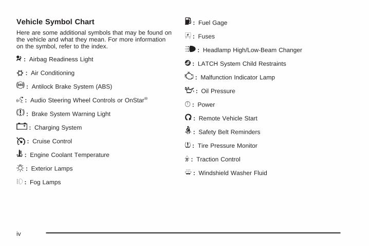
Vehicle Symbol ChartHere are some additional symbols that may be found onthe vehicle and what they mean. For more informationon the symbol, refer to the index.
9 : Airbag Readiness Light
# : Air Conditioning
! : Antilock Brake System (ABS)
g : Audio Steering Wheel Controls or OnStar®
$ : Brake System Warning Light
" : Charging System
I : Cruise Control
B : Engine Coolant Temperature
O : Exterior Lamps
# : Fog Lamps
. : Fuel Gage
+ : Fuses
i : Headlamp High/Low-Beam Changer
j : LATCH System Child Restraints
* : Malfunction Indicator Lamp
: : Oil Pressure
} : Power
/ : Remote Vehicle Start
> : Safety Belt Reminders
7 : Tire Pressure Monitor
F : Traction Control
M : Windshield Washer Fluid
iv

Front Seats ......................................................1-2Manual Seats ................................................1-2Seat Height Adjuster .......................................1-3Power Seat ...................................................1-3Manual Lumbar ..............................................1-4Heated Seats .................................................1-4Manual Reclining Seatbacks .............................1-5Head Restraints .............................................1-7Passenger Folding Seatback ............................1-8
Rear Seats .....................................................1-10Split Folding Rear Seat .................................1-10
Safety Belts ...................................................1-12Safety Belts: They Are for Everyone ................1-12How to Wear Safety Belts Properly .................1-17Lap-Shoulder Belt .........................................1-25Safety Belt Use During Pregnancy ..................1-30Safety Belt Extender .....................................1-30
Child Restraints .............................................1-31Older Children ..............................................1-31Infants and Young Children ............................1-34Child Restraint Systems .................................1-37
Where to Put the Restraint .............................1-40Lower Anchors and Tethers for
Children (LATCH) ......................................1-42Securing a Child Restraint in a Rear
Seat Position ............................................1-49Securing a Child Restraint in the Right Front
Seat Position ............................................1-52Airbag System ...............................................1-55
Where Are the Airbags? ................................1-58When Should an Airbag Inflate? .....................1-60What Makes an Airbag Inflate? .......................1-61How Does an Airbag Restrain? .......................1-61What Will You See After an Airbag Inflates? .....1-62Passenger Sensing System ............................1-63Servicing Your Airbag-Equipped Vehicle ...........1-68Adding Equipment to Your Airbag-Equipped
Vehicle ....................................................1-68Restraint System Check ..................................1-70
Checking the Restraint Systems ......................1-70Replacing Restraint System Parts
After a Crash ............................................1-71
Section 1 Seats and Restraint System
1-1

Front Seats
Manual Seats
{CAUTION:
You can lose control of the vehicle if you try toadjust a manual driver’s seat while the vehicle ismoving. The sudden movement could startle andconfuse you, or make you push a pedal when youdo not want to. Adjust the driver’s seat only whenthe vehicle is not moving.
If the vehicle has a manual seat, it can be movedforward or rearward.
1. Lift the bar to unlockthe seat.
2. Slide the seat to thedesired position andrelease the bar.
Try to move the seat with your body to be sure the seatis locked in place.
1-2

Seat Height Adjuster
To manually raise or lower the seat, move the leverrepeatedly upward or downward.
Power Seat
To adjust the seat:
• Slide the control forward or rearward to move theseat forward or rearward.
• Move the front and rear of the control up or down toraise or lower the front and rear part of the seatcushion.
1-3

Manual Lumbar
On vehicles with thisfeature, the knob islocated on the front of thedriver seat lower cushionon the inboard side.
Turn the knob clockwise or counterclockwise to increaseor decrease the lumbar support.
Heated Seats
If your vehicle has heatedseats, the switches arelocated on the instrumentpanel near the climatecontrols.
The ignition must be on for the heated seats to operate.
Press the switch, nearest to the seat, once to turn theheated seat on to the high setting. Both indicator lightswill be lit. Press the switch a second time to turn theheated seat to the low setting. One indicator light willbe lit. Press the switch a third time to turn the heatedseat off.
If your vehicle has remote vehicle start and is startedusing the remote keyless entry transmitter, the heatedseats may automatically turn on if it is cold outside. See“Remote Vehicle Start” under Remote Keyless Entry(RKE) System Operation on page 2-5. When the key isinserted into the ignition and the ignition is turned to RUN,the heated seat feature will turn off. To turn the heatedseats back on, press the desired button.
1-4

Manual Reclining Seatbacks
{CAUTION:
You can lose control of the vehicle if you try toadjust a manual driver’s seat while the vehicle ismoving. The sudden movement could startle andconfuse you, or make you push a pedal when youdo not want to. Adjust the driver’s seat only whenthe vehicle is not moving.
{CAUTION:
If either seatback is not locked, it could moveforward in a sudden stop or crash. That couldcause injury to the person sitting there. Alwayspush and pull on the seatbacks to be sure theyare locked.
To adjust the seatback, lift the lever on the outboard sideof the seat and move the seatback to the desired position.Then release the lever to lock the seatback in place. If thepassenger’s seat is a flat folding seat, fully raise the leverto disengage the seatback.
Driver’s Seat shown, Passenger Seat similar
1-5

{CAUTION:
Sitting in a reclined position when the vehicle is inmotion can be dangerous. Even when buckled up,the safety belts cannot do their job when reclinedlike this.
The shoulder belt cannot do its job because it willnot be against your body. Instead, it will be in frontof you. In a crash, you could go into it, receivingneck or other injuries.
The lap belt cannot do its job either. In a crash,the belt could go up over your abdomen. The beltforces would be there, not at your pelvic bones.This could cause serious internal injuries.
For proper protection when the vehicle is inmotion, have the seatback upright. Then sit wellback in the seat and wear the safety belt properly.
Do not have a seatback reclined if your vehicle ismoving.
1-6

Head Restraints
Adjust the head restraint so that the top of the restraintis at the same height as the top of the occupant’shead. This position reduces the chance of a neck injuryin a crash.
Pull the head restraint up toraise it. To lower the headrestraint, press the button,located on the top of theseatback, and push therestraint down.
1-7

Passenger Folding Seatback
{CAUTION:
If you fold the seatback forward to carry longerobjects, such as skis, be sure any such cargo isnot near an airbag. In a crash, an inflating airbagmight force that object toward a person. This couldcause severe injury or even death. Secure objectsaway from the area in which an airbag wouldinflate. For more information, see Where Are theAirbags? on page 1-58 and Loading the Vehicleon page 4-20.
{CAUTION:
Things you put on this seatback can strike andinjure people in a sudden stop or turn, or in acrash. Remove or secure all items before driving.
On vehicles with this feature, to fold the seatback:
1. Lower the head restraint all the way.
2. Lift the bar under the front of the seat to unlock it.Slide the seat as far back as it will go and releasethe bar. Try to move the seat back and forth tomake sure it is locked into place.
3. Lift up fully on the recliner lever, located on theoutboard side of the seat, and fold the seatbackforward until it disengages.
1-8
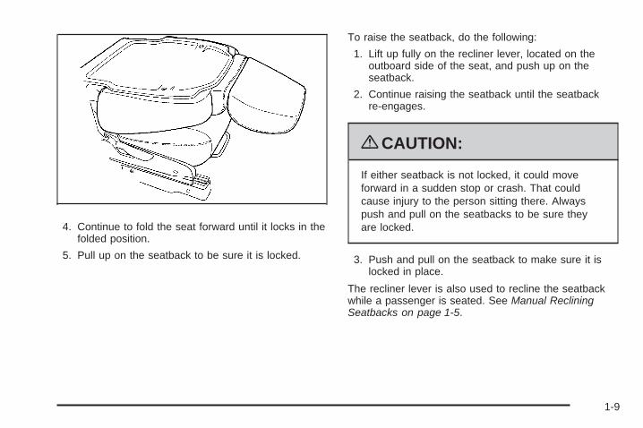
4. Continue to fold the seat forward until it locks in thefolded position.
5. Pull up on the seatback to be sure it is locked.
To raise the seatback, do the following:
1. Lift up fully on the recliner lever, located on theoutboard side of the seat, and push up on theseatback.
2. Continue raising the seatback until the seatbackre-engages.
{CAUTION:
If either seatback is not locked, it could moveforward in a sudden stop or crash. That couldcause injury to the person sitting there. Alwayspush and pull on the seatbacks to be sure theyare locked.
3. Push and pull on the seatback to make sure it islocked in place.
The recliner lever is also used to recline the seatbackwhile a passenger is seated. See Manual RecliningSeatbacks on page 1-5.
1-9

Rear Seats
Split Folding Rear SeatThe rear split bench seatbacks have three availablepositions — folded forward, upright, or partially reclined.Both of the seatbacks can be moved to any of thethree positions independent of the other seatbackposition. The rear bench seat can also be movedforward and rearward.
{CAUTION:
If either seatback is not locked, it could moveforward in a sudden stop or crash. That couldcause injury to the person sitting there. Alwayspush and pull on the seatbacks to be sure theyare locked.
{CAUTION:
A safety belt that is improperly routed, not properlyattached, or twisted will not provide the protectionneeded in a crash. The person wearing the beltcould be seriously injured. After raising the rearseatback, always check to be sure that the safetybelts are properly routed and attached, and arenot twisted.
To fold the seatback down, do the following:
Notice: Folding a rear seat with the safety beltsstill fastened may cause damage to the seat or thesafety belts. Always unbuckle the safety beltsand return them to their normal stowed positionbefore folding a rear seat.
1. Ensure all three of the safety belts are unbuckledand the front seatbacks are not reclined.
1-10

2. Lift the lever located on the top of the seatback torelease the seatback.
3. Fold the seatback forward to the desired position.
To recline the seatback, do the following:
1. Lift and hold the lever located on top of theseatback.
2. Tilt the seatback rearward, then release the leverwhen the seatback is in the desired position.
To slide the entire seat forward or rearward, do thefollowing:
1. Lift and hold the release bar located under the frontof the seat cushion to unlock the seat.
2. Slide the seat to the desired position.
3. Release the bar.
4. Try to move the seat back and forth to ensure theseat is locked in place.
1-11

Safety Belts
Safety Belts: They Are for EveryoneThis section of the manual describes how to usesafety belts properly. It also describes some things notto do with safety belts.
{CAUTION:
Do not let anyone ride where a safety belt cannotbe worn properly. In a crash, if you or yourpassenger(s) are not wearing safety belts, theinjuries can be much worse. You can hit thingsinside the vehicle harder or be ejected from thevehicle. You and your passenger(s) can beseriously injured or killed. In the same crash, youmight not be, if you are buckled up. Always fastenyour safety belt, and check that your passenger(s)are restrained properly too.
{CAUTION:
It is extremely dangerous to ride in a cargo area,inside or outside of a vehicle. In a collision, peopleriding in these areas are more likely to be seriouslyinjured or killed. Do not allow people to ride in anyarea of your vehicle that is not equipped with seatsand safety belts. Be sure everyone in your vehicle isin a seat and using a safety belt properly.
This vehicle has indicators as a reminder to buckle thesafety belts. See Safety Belt Reminders on page 3-27for additional information.In most states and in all Canadian provinces, the lawrequires wearing safety belts. Here is why:You never know if you will be in a crash. If you do havea crash, you do not know if it will be a serious one.A few crashes are mild, and some crashes can be soserious that even buckled up, a person would not survive.But most crashes are in between. In many of them,people who buckle up can survive and sometimes walkaway. Without safety belts, they could have been badlyhurt or killed.After more than 40 years of safety belts in vehicles,the facts are clear. In most crashes buckling up doesmatter... a lot!
1-12

Why Safety Belts WorkWhen you ride in or on anything, you go as fast asit goes.
Take the simplest vehicle. Suppose it is just a seat onwheels.
Put someone on it.
1-13

Get it up to speed. Then stop the vehicle. The riderdoes not stop.
The person keeps going until stopped by something.In a real vehicle, it could be the windshield...
1-14

or the instrument panel... or the safety belts!
With safety belts, you slow down as the vehicle does.You get more time to stop. You stop over more distance,and your strongest bones take the forces. That is whysafety belts make such good sense.
1-15

Questions and Answers About SafetyBelts
Q: Will I be trapped in the vehicle after a crash if Iam wearing a safety belt?
A: You could be — whether you are wearing a safetybelt or not. But your chance of being consciousduring and after an accident, so you can unbuckleand get out, is much greater if you are belted.And you can unbuckle a safety belt, even if youare upside down.
Q: If my vehicle has airbags, why should I have towear safety belts?
A: Airbags are supplemental systems only; so theywork with safety belts — not instead of them.Whether or not an airbag is provided, all occupantsstill have to buckle up to get the most protection.That is true not only in frontal collisions, butespecially in side and other collisions.
Q: If I am a good driver, and I never drive far fromhome, why should I wear safety belts?
A: You may be an excellent driver, but if you are in acrash — even one that is not your fault — you andyour passenger(s) can be hurt. Being a good driverdoes not protect you from things beyond yourcontrol, such as bad drivers.
Most accidents occur within 25 miles (40 km)of home. And the greatest number of seriousinjuries and deaths occur at speeds of less than40 mph (65 km/h).
Safety belts are for everyone.
1-16

How to Wear Safety Belts ProperlyThis section is only for people of adult size.
Be aware that there are special things to know aboutsafety belts and children. And there are different rules forsmaller children and infants. If a child will be riding in thevehicle, see Older Children on page 1-31 or Infants andYoung Children on page 1-34. Follow those rules foreveryone’s protection.
It is very important for all occupants to buckle up.Statistics show that unbelted people are hurt more oftenin crashes than those who are wearing safety belts.
Occupants who are not buckled up can be thrown out ofthe vehicle in a crash. And they can strike others in thevehicle who are wearing safety belts.
First, before you or your passenger(s) wear a safetybelt, there is important information you should know. Sit up straight and always keep your feet on the floor in
front of you. The lap part of the belt should be worn lowand snug on the hips, just touching the thighs. In a crash,this applies force to the strong pelvic bones and youwould be less likely to slide under the lap belt. If you slidunder it, the belt would apply force on your abdomen.This could cause serious or even fatal injuries. Theshoulder belt should go over the shoulder and across thechest. These parts of the body are best able to take beltrestraining forces.The shoulder belt locks if there is a sudden stop orcrash.
1-17

Q: What is wrong with this?
A: The shoulder belt is too loose. It will not give asmuch protection this way.
{CAUTION:
You can be seriously hurt if your shoulder belt istoo loose. In a crash, you would move forward toomuch, which could increase injury. The shoulderbelt should fit snugly against your body.
1-18

Q: What is wrong with this?
A: The lap belt is too loose. It will not give nearly asmuch protection this way.
{CAUTION:
You can be seriously hurt if your lap belt is tooloose. In a crash, you could slide under the lapbelt and apply force on your abdomen. This couldcause serious or even fatal injuries. The lap beltshould be worn low and snug on the hips, justtouching the thighs.
1-19

Q: What is wrong with this?
A: The belt is buckled in the wrong buckle.
{CAUTION:
You can be seriously injured if your belt is buckledin the wrong place like this. In a crash, the beltwould go up over your abdomen. The belt forceswould be there, not on the pelvic bones. Thiscould cause serious internal injuries. Alwaysbuckle your belt into the buckle nearest you.
1-20

Q: What is wrong with this?
A: The belt is over an armrest.
{CAUTION:
You can be seriously injured if your belt goes overan armrest like this. The belt would be much toohigh. In a crash, you can slide under the belt. Thebelt force would then be applied on the abdomen,not on the pelvic bones, and that could causeserious or fatal injuries. Be sure the belt goesunder the armrests.
1-21

Q: What is wrong with this?
A: The shoulder belt is worn under the arm. It shouldbe worn over the shoulder at all times.
{CAUTION:
You can be seriously injured if you wear theshoulder belt under your arm. In a crash, yourbody would move too far forward, which wouldincrease the chance of head and neck injury.Also, the belt would apply too much force to theribs, which are not as strong as shoulder bones.You could also severely injure internal organs likeyour liver or spleen. The shoulder belt should goover the shoulder and across the chest.
1-22

Q: What is wrong with this?
A: The belt is behind the body.
{CAUTION:
You can be seriously injured by not wearing thelap-shoulder belt properly. In a crash, you wouldnot be restrained by the shoulder belt. Your bodycould move too far forward increasing the chanceof head and neck injury. You might also slideunder the lap belt. The belt force would then beapplied right on the abdomen. That could causeserious or fatal injuries. The shoulder belt shouldgo over the shoulder and across the chest.
1-23

Q: What is wrong with this?
A: The belt is twisted across the body.
{CAUTION:
You can be seriously injured by a twisted belt. In acrash, you would not have the full width of the beltto spread impact forces. If a belt is twisted, makeit straight so it can work properly, or ask yourdealer/retailer to fix it.
1-24

Lap-Shoulder BeltAll seating positions in the vehicle have alap-shoulder belt.
The following instructions explain how to wear alap-shoulder belt properly.
1. Adjust the seat, if the seat is adjustable, so you cansit up straight. To see how, see “Seats” in the Index.
2. Pick up the latch plate and pull the belt across you.Do not let it get twisted.The lap-shoulder belt may lock if you pull the beltacross you very quickly. If this happens, let the beltgo back slightly to unlock it. Then pull the belt acrossyou more slowly.If the shoulder portion of a passenger belt is pulledout all the way, the child restraint locking feature maybe engaged. If this happens, let the belt go back allthe way and start again.
3. Push the latch plate into the buckle until it clicks.Pull up on the latch plate to make sure it is secure.If the belt is not long enough, see Safety BeltExtender on page 1-30.Position the release button on the buckle so thatthe safety belt could be quickly unbuckled ifnecessary.
4. If equipped with a shoulder belt height adjuster,move it to the height that is right for you.See “Shoulder Belt Height Adjustment” laterin this section for instructions on use andimportant safety information.
1-25

5. To make the lap part tight, pull up on theshoulder belt.It may be necessary to pull stitching on the safetybelt through the latch plate to fully tighten the lap belton smaller occupants.
To unlatch the belt, just push the button on the buckle.For outboard seating positions, slide the latch plate upthe safety belt webbing when the safety belt is not in use.The latch plate should rest on the stitching on the safetybelt, near the guide loop.
Before a door is closed, be sure the safety belt is outof the way. If a door is slammed against a safety belt,damage can occur to both the safety belt and the vehicle.
1-26

Shoulder Belt Height AdjusterThe vehicle has a shoulder belt height adjuster for thedriver and right front passenger seating positions.
Adjust the height so that the shoulder portion of the beltis centered on the shoulder. The belt should be awayfrom the face and neck, but not falling off the shoulder.Improper shoulder belt height adjustment could reducethe effectiveness of the safety belt in a crash.
Squeeze the releasebuttons (A) together andmove the height adjusterto the desired position.
After the height adjuster is set to the desired position,try to move it up or down without squeezing the releasebuttons to make sure it has locked into position.
Safety Belt PretensionersThis vehicle has safety belt pretensioners for frontoutboard occupants. Although the safety beltpretensioners cannot be seen, they are part of thesafety belt assembly. They can help tighten the safetybelts during the early stages of a moderate to severefrontal and near frontal crash if the threshold conditionsfor pretensioner activation are met.
Pretensioners work only once. If the pretensionersactivate in a crash, they will need to be replaced,and probably other new parts for the vehicle’s safetybelt system. See Replacing Restraint System PartsAfter a Crash on page 1-71.
Rear Safety Belt Comfort GuidesRear shoulder belt comfort guides may provide addedsafety belt comfort for older children who have outgrownbooster seats and for some adults. When installed ona shoulder belt, the comfort guide positions the beltaway from the neck and head.
1-27

There is one guide for each outside passenger positionin the rear seat. Here is how to install a comfortguide to the safety belt:
1. Remove the guide from its storage clip on the backof the seatback.
2. Place the guide over the belt, and insert the twoedges of the belt into the slots of the guide.
3. Be sure that the belt is not twisted and it lies flat.The elastic cord must be under the belt and theguide on top.
1-28

{CAUTION:
A safety belt that is not properly worn may notprovide the protection needed in a crash. Theperson wearing the belt could be seriously injured.The shoulder belt should go over the shoulder andacross the chest. These parts of the body are bestable to take belt restraining forces.
4. Buckle, position, and release the safety belt asdescribed previously in this section. Make surethat the shoulder belt crosses the shoulder.
To remove and store the comfort guide, squeeze the beltedges together so that the safety belt can be removedfrom the guide. Slide the guide back onto its storage cliplocated on the seatback.
1-29

Safety Belt Use During PregnancySafety belts work for everyone, including pregnantwomen. Like all occupants, they are more likely to beseriously injured if they do not wear safety belts.
A pregnant woman should wear a lap-shoulder belt, andthe lap portion should be worn as low as possible, belowthe rounding, throughout the pregnancy.
The best way to protect the fetus is to protect themother. When a safety belt is worn properly, it ismore likely that the fetus will not be hurt in a crash.For pregnant women, as for anyone, the key to makingsafety belts effective is wearing them properly.
Safety Belt ExtenderIf the vehicle’s safety belt will fasten around you, youshould use it.
But if a safety belt is not long enough, your dealer/retailerwill order you an extender. When you go in to order it,take the heaviest coat you will wear, so the extender willbe long enough for you. To help avoid personal injury, donot let someone else use it, and use it only for the seat itis made to fit. The extender has been designed for adults.Never use it for securing child seats. To wear it, attach itto the regular safety belt. For more information, see theinstruction sheet that comes with the extender.
1-30

Child Restraints
Older Children
Older children who have outgrown booster seats shouldwear the vehicle’s safety belts.
The manufacturer’s instructions that come with thebooster seat state the weight and height limitations forthat booster. Use a booster seat with a lap-shoulder beltuntil the child passes the below fit test:
• Sit all the way back on the seat. Do the knees bendat the seat edge? If yes, continue. If no, return tothe booster seat.
• Buckle the lap-shoulder belt. Does the shoulder beltrest on the shoulder? If yes, continue. If no, try usingthe rear safety belt comfort guide. See “Rear SafetyBelt Comfort Guides” under Lap-Shoulder Belt onpage 1-25 for more information. If the shoulder beltstill does not rest on the shoulder, then return to thebooster seat.
• Does the lap belt fit low and snug on the hips,touching the thighs? If yes, continue. If no, return tothe booster seat.
• Can proper safety belt fit be maintained for the lengthof the trip? If yes, continue. If no, return to thebooster seat.
• If you have the choice, a child should sit in a positionwith a lap-shoulder belt and get the additionalrestraint a shoulder belt can provide.
1-31

Q: What is the proper way to wear safety belts?
A: An older child should wear a lap-shoulder belt andget the additional restraint a shoulder belt canprovide. The shoulder belt should not cross the faceor neck. The lap belt should fit snugly below the hips,just touching the top of the thighs. This applies beltforce to the child’s pelvic bones in a crash. It shouldnever be worn over the abdomen, which could causesevere or even fatal internal injuries in a crash.
Also see “Rear Safety Belt Comfort Guides” underLap-Shoulder Belt on page 1-25.
According to accident statistics, children and infantsare safer when properly restrained in a child restraintsystem or infant restraint system secured in a rearseating position.
In a crash, children who are not buckled up can strikeother people who are buckled up, or can be thrownout of the vehicle. Older children need to use safetybelts properly.
{CAUTION:
Never do this.
Never allow two children to wear the same safetybelt. The safety belt can not properly spread theimpact forces. In a crash, the two children can becrushed together and seriously injured. A safetybelt must be used by only one person at a time.
1-32

{CAUTION:
Never do this.
Never allow a child to wear the safety belt with theshoulder belt behind their back. A child can beseriously injured by not wearing the lap-shoulderbelt properly. In a crash, the child would not berestrained by the shoulder belt. The child couldmove too far forward increasing the chance ofhead and neck injury. The child might also slideunder the lap belt. The belt force would then beapplied right on the abdomen. That could causeserious or fatal injuries. The shoulder belt shouldgo over the shoulder and across the chest.
1-33

Infants and Young ChildrenEveryone in a vehicle needs protection! This includesinfants and all other children. Neither the distancetraveled nor the age and size of the traveler changesthe need, for everyone, to use safety restraints. In fact,the law in every state in the United States and in everyCanadian province says children up to some age mustbe restrained while in a vehicle.
{CAUTION:
Children can be seriously injured or strangled if ashoulder belt is wrapped around their neck andthe safety belt continues to tighten. Never leavechildren unattended in a vehicle and never allowchildren to play with the safety belts.
Airbags plus lap-shoulder belts offer protection for adultsand older children, but not for young children and infants.Neither the vehicle’s safety belt system nor its airbag
system is designed for them. Every time infants andyoung children ride in vehicles, they should have theprotection provided by appropriate child restraints.
Children who are not restrained properly can strike otherpeople, or can be thrown out of the vehicle.
{CAUTION:
Never do this.
Never hold an infant or a child while riding in avehicle. Due to crash forces, an infant or a childwill become so heavy it is not possible to hold itduring a crash. For example, in a crash at only40 km/h (25 mph), a 5.5 kg (12 lb) infant willsuddenly become a 110 kg (240 lb) force on aperson’s arms. An infant should be secured in anappropriate restraint.
1-34

{CAUTION:
Never do this.
Children who are up against, or very close to, anyairbag when it inflates can be seriously injuredor killed. Never put a rear-facing child restraint inthe right front seat. Secure a rear-facing child
CAUTION: (Continued)
CAUTION: (Continued)
restraint in a rear seat. It is also better to secure aforward-facing child restraint in a rear seat. If youmust secure a forward-facing child restraint in theright front seat, always move the front passengerseat as far back as it will go.
1-35

Q: What are the different types of add-on childrestraints?
A: Add-on child restraints, which are purchased by thevehicle’s owner, are available in four basic types.Selection of a particular restraint should take intoconsideration not only the child’s weight, height,and age but also whether or not the restraint willbe compatible with the motor vehicle in which it willbe used.
For most basic types of child restraints, there aremany different models available. When purchasing achild restraint, be sure it is designed to be used in amotor vehicle. If it is, the restraint will have a labelsaying that it meets federal motor vehicle safetystandards.
The restraint manufacturer’s instructions thatcome with the restraint state the weight and heightlimitations for a particular child restraint. In addition,there are many kinds of restraints available forchildren with special needs.
{CAUTION:
To reduce the risk of neck and head injury duringa crash, infants need complete support. This isbecause an infant’s neck is not fully developedand its head weighs so much compared withthe rest of its body. In a crash, an infant in arear-facing child restraint settles into the restraint,so the crash forces can be distributed across thestrongest part of an infant’s body, the back andshoulders. Infants should always be secured inrear-facing child restraints.
1-36

{CAUTION:
A young child’s hip bones are still so small thatthe vehicle’s regular safety belt may not remainlow on the hip bones, as it should. Instead, it maysettle up around the child’s abdomen. In a crash,the belt would apply force on a body area that isunprotected by any bony structure. This alonecould cause serious or fatal injuries. To reducethe risk of serious or fatal injuries during a crash,young children should always be secured inappropriate child restraints.
Child Restraint Systems
A rear-facing infant seat (A)provides restraint with theseating surface against theback of the infant.
The harness system holds the infant in place and, in acrash, acts to keep the infant positioned in the restraint.
1-37

A forward-facing childseat (B) provides restraintfor the child’s bodywith the harness.
A booster seat (C-D) is a child restraint designed toimprove the fit of the vehicle’s safety belt system.A booster seat can also help a child to see out thewindow.
1-38
Securing an Add-On Child Restraint inthe Vehicle
{CAUTION:
A child can be seriously injured or killed in a crashif the child restraint is not properly secured in thevehicle. Secure the child restraint properly in thevehicle using the vehicle’s safety belt or LATCHsystem, following the instructions that came withthat child restraint and the instructions in thismanual.
To help reduce the chance of injury, the child restraintmust be secured in the vehicle. Child restraint systemsmust be secured in vehicle seats by lap belts or thelap belt portion of a lap-shoulder belt, or by the LATCHsystem. See Lower Anchors and Tethers for Children(LATCH) on page 1-42 for more information. A child canbe endangered in a crash if the child restraint is notproperly secured in the vehicle.
When securing an add-on child restraint, refer to theinstructions that come with the restraint which may beon the restraint itself or in a booklet, or both, and to thismanual. The child restraint instructions are important,so if they are not available, obtain a replacementcopy from the manufacturer.
Keep in mind that an unsecured child restraint canmove around in a collision or sudden stop and injurepeople in the vehicle. Be sure to properly secureany child restraint in the vehicle — even whenno child is in it.
Securing the Child Within the ChildRestraint
{CAUTION:
A child can be seriously injured or killed in a crashif the child is not properly secured in the childrestraint. Secure the child properly following theinstructions that came with that child restraint.
1-39

Where to Put the RestraintAccident statistics show that children are safer if theyare restrained in the rear rather than the front seat.
We recommend that children and child restraintsbe secured in a rear seat, including: an infant or a childriding in a rear-facing child restraint; a child riding ina forward-facing child seat; an older child riding ina booster seat; and children, who are large enough,using safety belts.
A label on your sun visor says, “Never put a rear-facingchild seat in the front.” This is because the risk to therear-facing child is so great, if the airbag deploys.
{CAUTION:
A child in a rear-facing child restraint can beseriously injured or killed if the right front passengerairbag inflates. This is because the back of therear-facing child restraint would be very close to the
CAUTION: (Continued)
CAUTION: (Continued)
inflating airbag. A child in a forward-facing childrestraint can be seriously injured or killed if theright front passenger airbag inflates and thepassenger seat is in a forward position.
Even if the passenger sensing system has turnedoff the right front passenger frontal airbag, nosystem is fail-safe. No one can guarantee thatan airbag will not deploy under some unusualcircumstance, even though it is turned off.
Secure rear-facing child restraints in a rearseat, even if the airbag is off. If you secure aforward-facing child restraint in the right front seat,always move the front passenger seat as far backas it will go. It is better to secure the child restraintin a rear seat.
See Passenger Sensing System on page 1-63 foradditional information.
1-40
When securing a child restraint in a rear seatingposition, study the instructions that came with your childrestraint to make sure it is compatible with this vehicle.
If your vehicle does not have a rear seat that willaccommodate a rear-facing child restraint, werecommend that rear-facing child restraints not betransported in your vehicle, even if the airbag is off.
Wherever you install a child restraint, be sure to securethe child restraint properly.
Keep in mind that an unsecured child restraint canmove around in a collision or sudden stop and injurepeople in the vehicle. Be sure to properly secureany child restraint in your vehicle — even whenno child is in it.
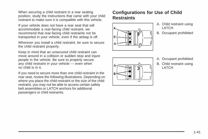
If you need to secure more than one child restraint in therear seat, review the following illustrations. Depending onwhere you place the child restraint or the size of the childrestraint, you may not be able to access certain safetybelt assemblies or LATCH anchors for additionalpassengers or child restraints.
Configurations for Use of ChildRestraints
A. Child restraint usingLATCH
B. Occupant prohibited
A. Occupant prohibitedB. Child restraint using
LATCH
1-41

A. Child restraint usingLATCH
B. Occupant prohibitedC. Child restraint or
occupant usingsafety belt
A. Child restraint oroccupant usingsafety belt
A. Child restraint oroccupant usingsafety belt
B. Child restraint usingLATCH
Lower Anchors and Tethers forChildren (LATCH)The LATCH system holds a child restraint during drivingor in a crash. This system is designed to make installationof a child restraint easier. The LATCH system usesanchors in the vehicle and attachments on the childrestraint that are made for use with the LATCH system.
Make sure that a LATCH-compatible child restraint isproperly installed using the anchors, or use the vehicle’ssafety belts to secure the restraint, following theinstructions that came with that restraint, and also theinstructions in this manual. When installing a childrestraint with a top tether, you must also use either thelower anchors or the safety belts to properly secure thechild restraint. A child restraint must never be installedusing only the top tether and anchor.
In order to use the LATCH system in your vehicle, youneed a child restraint that has LATCH attachments.The child restraint manufacturer will provide you withinstructions on how to use the child restraint and itsattachments. The following explains how to attach achild restraint with these attachments in your vehicle.
Not all vehicle seating positions or child restraints havelower anchors and attachments or top tether anchorsand attachments.
1-42

Lower Anchors
Lower anchors (A) are metal bars built into the vehicle.There are two lower anchors for each LATCH seatingposition that will accommodate a child restraint withlower attachments (B).
Top Tether Anchor
A top tether (A, C) anchors the top of the child restraint tothe vehicle. A top tether anchor is built into the vehicle.The top tether attachment (B) on the child restraintconnects to the top tether anchor in the vehicle in orderto reduce the forward movement and rotation of the childrestraint during driving or in a crash.
Your child restraint may have a single tether (A) or adual tether (C). Either will have a single attachment (B)to secure the top tether to the anchor.
1-43

Some child restraints that have a top tether are designedfor use with or without the top tether being attached.Others require the top tether always to be attached.In Canada, the law requires that forward-facingchild restraints have a top tether, and that the tetherbe attached. Be sure to read and follow the instructionsfor your child restraint.
If the child restraint does not have a top tether, onecan be obtained, in kit form, for many child restraints.Ask the child restraint manufacturer whether or not akit is available.
Lower Anchor and Top Tether AnchorLocations
i (Top Tether Anchor):Seating positions with toptether anchors.
j (Lower Anchor): Seatingpositions with two loweranchors.
Each rear seating position has exposed metal anchorslocated in the crease between the seatback and theseat cushion.
Rear Seat
1-44

The top tether anchors for each rear seating position arelocated on the back of the rear seatback. You may needto adjust the rear compartment storage panel/cover in the
rear cargo area to access the anchors. Be sure to use ananchor located on the same side of the vehicle as theseating position where the child restraint will be placed.
Do not secure a child restraint in a position without atop tether anchor if a national or local law requires thatthe top tether be attached, or if the instructions thatcome with the child restraint say that the top tether mustbe attached.
Accident statistics show that children are safer if theyare restrained in the rear rather than the front seat.See Where to Put the Restraint on page 1-40 foradditional information.
1-45

Securing a Child Restraint Designed forthe LATCH System
{CAUTION:
If a LATCH-type child restraint is not attached toanchors, the child restraint will not be able to protectthe child correctly. In a crash, the child could beseriously injured or killed. Install a LATCH-typechild restraint properly using the anchors, or usethe vehicle’s safety belts to secure the restraint,following the instructions that came with the childrestraint and the instructions in this manual.
{CAUTION:
Do not attach more than one child restraint to asingle anchor. Attaching more than one childrestraint to a single anchor could cause the anchoror attachment to come loose or even break duringa crash. A child or others could be injured. Toreduce the risk of serious or fatal injuries during acrash, attach only one child restraint per anchor.
{CAUTION:
Children can be seriously injured or strangled if ashoulder belt is wrapped around their neck andthe safety belt continues to tighten. Buckle anyunused safety belts behind the child restraint sochildren cannot reach them. Pull the shoulder beltall the way out of the retractor to set the lock, ifyour vehicle has one, after the child restraint hasbeen installed.
Notice: Do not let the LATCH attachments rubagainst the vehicle’s safety belts. This may damagethese parts. If necessary, move buckled safetybelts to avoid rubbing the LATCH attachments.
Do not fold the empty rear seat with a safety beltbuckled. This could damage the safety belt orthe seat. Unbuckle and return the safety belt toits stowed position, before folding the seat.
1-46

A. Passenger’s Side Rear Seat Lower AnchorsB. Center Rear Seat Lower AnchorsC. Driver’s Side Rear Seat Lower Anchors
Make sure to attach the child restraint at the properanchor location.
This system is designed to make installation of childrestraints easier. When using lower anchors, do not usethe vehicle’s safety belts. Instead use the vehicle’s
anchors and child restraint attachments to secure therestraints. Some restraints also use another vehicleanchor to secure a top tether.
1. Attach and tighten the lower attachments to thelower anchors. If the child restraint does not havelower attachments or the desired seating positiondoes not have lower anchors, secure the childrestraint with the top tether and the safety belts.Refer to your child restraint manufacturerinstructions and the instructions in this manual.
1.1. Find the lower anchors for the desiredseating position.
1.2. Put the child restraint on the seat.1.3. Attach and tighten the lower attachments on
the child restraint to the lower anchors.
2. If the child restraint manufacturer recommends thatthe top tether be attached, attach and tighten thetop tether to the top tether anchor, if equipped.Refer to the child restraint instructions and thefollowing steps:
2.1. Find the top tether anchor.2.2. You may need to adjust the rear
compartment storage panel/cover inthe rear cargo area to access the anchors.See Rear Compartment Storage Panel/Cover on page 2-44.
1-47

2.3. Route, attach and tighten the top tetheraccording to your child restraint instructionsand the following instructions:
If the position you are usingdoes not have a headrestor head restraint and youare using a single tether,route the tether over theseatback.
If the position you are usingdoes not have a headrestor head restraint and youare using a dual tether,route the tether over theseatback.
If the position you are usinghas an adjustable headrestor head restraint and youare using a dual tether,route the tether around theheadrest or head restraint.
If the position you are usinghas an adjustable headrestor head restraint and youare using a single tether,raise the headrest or headrestraint and route thetether under the headrestor head restraint and inbetween the headrest orhead restraint posts.
3. Push and pull the child restraint in differentdirections to be sure it is secure.
1-48

Securing a Child Restraint in a RearSeat PositionWhen securing a child restraint in a rear seating position,study the instructions that came with the child restraint tomake sure it is compatible with this vehicle.
If the child restraint has the LATCH system, see LowerAnchors and Tethers for Children (LATCH) on page 1-42for how and where to install the child restraint usingLATCH. If a child restraint is secured in the vehicle usinga safety belt and it uses a top tether, see Lower Anchorsand Tethers for Children (LATCH) on page 1-42 for toptether anchor locations.
Do not secure a child seat in a position without a toptether anchor if a national or local law requires that thetop tether be anchored, or if the instructions that comewith the child restraint say that the top strap must beanchored.
In Canada, the law requires that forward-facing childrestraints have a top tether, and that the tether beattached.
If the child restraint does not have the LATCH system,you will be using the safety belt to secure the childrestraint in this position. Be sure to follow the instructionsthat came with the child restraint. Secure the child in thechild restraint when and as the instructions say.
If more than one child restraint needs to be installedin the rear seat, be sure to read Where to Put theRestraint on page 1-40.
1. Put the child restraint on the seat.
2. Pick up the latch plate, and run the lap and shoulderportions of the vehicle’s safety belt through oraround the restraint. The child restraint instructionswill show you how.
1-49

3. Push the latch plate into the buckle until it clicks.Position the release button on the buckle so thatthe safety belt could be quickly unbuckled ifnecessary.
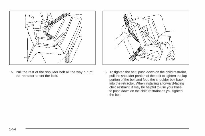
4. Pull the rest of the shoulder belt all the way out ofthe retractor to set the lock.
1-50

5. To tighten the belt, push down on the child restraint,pull the shoulder portion of the belt to tighten the lapportion of the belt and feed the shoulder belt backinto the retractor. When installing a forward-facingchild restraint, it may be helpful to use your kneeto push down on the child restraint as you tightenthe belt.
6. If the child restraint has a top tether, follow thechild restraint manufacturer’s instructions regardingthe use of the top tether. See Lower Anchorsand Tethers for Children (LATCH) on page 1-42for more information.
7. Push and pull the child restraint in differentdirections to be sure it is secure.
To remove the child restraint, unbuckle the vehicle safetybelt and let it return to the stowed position. If the toptether is attached to a top tether anchor, disconnect it.
1-51

Securing a Child Restraint in theRight Front Seat PositionThis vehicle has airbags. A rear seat is a safer place tosecure a forward-facing child restraint. See Where toPut the Restraint on page 1-40.
In addition, the vehicle has a passenger sensing systemwhich is designed to turn off the right front passengerfrontal airbag under certain conditions. See PassengerSensing System on page 1-63 and Passenger AirbagStatus Indicator on page 3-29 for more information,including important safety information.
A label on the sun visor says, “Never put a rear-facingchild seat in the front.” This is because the risk tothe rear-facing child is so great, if the airbag deploys.
{CAUTION:
A child in a rear-facing child restraint can beseriously injured or killed if the right front passengerairbag inflates. This is because the back of therear-facing child restraint would be very close tothe inflating airbag. A child in a forward-facing childrestraint can be seriously injured or killed if the rightfront passenger airbag inflates and the passengerseat is in a forward position.
Even if the passenger sensing system has turnedoff the right front passenger frontal airbag, nosystem is fail-safe. No one can guarantee thatan airbag will not deploy under some unusualcircumstance, even though it is turned off.
Secure rear-facing child restraints in a rearseat, even if the airbag is off. If you secure aforward-facing child restraint in the right front seat,always move the front passenger seat as far backas it will go. It is better to secure the child restraintin a rear seat.
See Passenger Sensing System on page 1-63 foradditional information.
1-52

If your child restraint has the LATCH system, see LowerAnchors and Tethers for Children (LATCH) on page 1-42for how and where to install the child restraint usingLATCH. If a child restraint is secured using a safety beltand it uses a top tether, see Lower Anchors and Tethersfor Children (LATCH) on page 1-42 for top tether anchorlocations.
Do not secure a child seat in a position without a toptether anchor if a national or local law requires that thetop tether be anchored, or if the instructions that comewith the child restraint say that the top strap must beanchored.
In Canada, the law requires that forward-facing childrestraints have a top tether, and that the tether beattached.
You will be using the lap-shoulder belt to secure thechild restraint in this position. Follow the instructionsthat came with the child restraint.
1. Move the seat as far back as it will go beforesecuring the forward-facing child restraint.When the passenger sensing system has turned offthe right front passenger’s frontal airbag, the offindicator on the passenger airbag status indicatorshould light and stay lit when you start the vehicle.See Passenger Airbag Status Indicator onpage 3-29.
2. Put the child restraint on the seat.
3. Pick up the latch plate, and run the lap and shoulderportions of the vehicle’s safety belt through oraround the restraint. The child restraint instructionswill show you how.
4. Push the latch plate into the buckle until it clicks.Position the release button on the buckle so thatthe safety belt could be quickly unbuckled ifnecessary.
1-53
5. Pull the rest of the shoulder belt all the way out ofthe retractor to set the lock.
6. To tighten the belt, push down on the child restraint,pull the shoulder portion of the belt to tighten the lapportion of the belt and feed the shoulder belt backinto the retractor. When installing a forward-facingchild restraint, it may be helpful to use your kneeto push down on the child restraint as you tightenthe belt.
1-54

7. If the vehicle does not have a rear seat and yourchild restraint has a top tether, follow the childrestraint manufacturer’s instructions regarding theuse of the top tether. See Lower Anchors andTethers for Children (LATCH) on page 1-42 formore information.
8. Push and pull the child restraint in differentdirections to be sure it is secure.
If the airbag is off, the off indicator in the passengerairbag status indicator will come on and stay on whenthe vehicle is started.
If a child restraint has been installed and the on indicatoris lit, see “If the On Indicator is Lit for a Child Restraint”under Passenger Sensing System on page 1-63 for moreinformation.
To remove the child restraint, unbuckle the vehicle safetybelt and let it return to the stowed position. If the toptether is attached to a top tether anchor, disconnect it.
Airbag SystemYour vehicle has the following airbags:
• A frontal airbag for the driver.
• A frontal airbag for the right front passenger.
Your vehicle may have the following airbags:
• A roof-rail airbag for the driver and the passengerseated directly behind the driver.
• A roof-rail airbag for the right front passengerand the passenger seated directly behind thatpassenger.
All of the airbags in your vehicle will have the wordAIRBAG embossed in the trim or on an attached labelnear the deployment opening.
For frontal airbags, the word AIRBAG will appear on themiddle part of the steering wheel for the driver andon the instrument panel for the right front passenger.
With roof-rail airbags, the word AIRBAG will appear alongthe headliner or trim.
1-55
Even if you do not have a right front passenger seat inyour vehicle there is still an active frontal airbag in theright side of the instrument panel. Do not place cargo infront of this airbag.
{CAUTION:
Be sure that cargo is not near an airbag. In acrash, an inflating airbag might force that objecttoward a person. This could cause severe injuryor even death. Secure objects away from thearea in which an airbag would inflate. For moreinformation, see Where Are the Airbags? onpage 1-58 and Loading the Vehicle on page 4-20.
Airbags are designed to supplement the protectionprovided by safety belts. Even though today’s airbagsare also designed to help reduce the risk of injuryfrom the force of an inflating bag, all airbags must inflatevery quickly to do their job.
Here are the most important things to know about theairbag system:
{CAUTION:
You can be severely injured or killed in a crash ifyou are not wearing your safety belt — even if youhave airbags. Airbags are designed to work withsafety belts, but do not replace them. Also, airbagsare not designed to deploy in every crash. In somecrashes safety belts are your only restraint. SeeWhen Should an Airbag Inflate? on page 1-60.
Wearing your safety belt during a crash helpsreduce your chance of hitting things inside thevehicle or being ejected from it. Airbags are“supplemental restraints” to the safety belts.Everyone in your vehicle should wear a safetybelt properly — whether or not there is an airbagfor that person.
1-56

{CAUTION:
Airbags inflate with great force, faster than the blinkof an eye. Anyone who is up against, or very closeto, any airbag when it inflates can be seriouslyinjured or killed. Do not sit unnecessarily close tothe airbag, as you would be if you were sitting onthe edge of your seat or leaning forward. Safetybelts help keep you in position before and during acrash. Always wear your safety belt, even withairbags. The driver should sit as far back aspossible while still maintaining control of thevehicle.
Occupants should not lean on or sleep against thedoor or side windows in seating positions withroof-rail airbags.
{CAUTION:
Children who are up against, or very close to, anyairbag when it inflates can be seriously injured orkilled. Airbags plus lap-shoulder belts offerprotection for adults and older children, but not foryoung children and infants. Neither the vehicle’ssafety belt system nor its airbag system is designedfor them. Young children and infants need theprotection that a child restraint system can provide.Always secure children properly in your vehicle.To read how, see Older Children on page 1-31or Infants and Young Children on page 1-34.
There is an airbagreadiness light on theinstrument panel cluster,which shows the airbagsymbol.
The system checks the airbag electrical system formalfunctions. The light tells you if there is an electricalproblem. See Airbag Readiness Light on page 3-28for more information.
1-57

Where Are the Airbags?
The driver’s airbag is in the middle of the steeringwheel.
The right front passenger’s airbag is in the instrumentpanel on the passenger’s side.
1-58

If your vehicle has roof-rail airbags for the driver, rightfront passenger, and second row outboard passengers,they are in the ceiling above the side windows.
{CAUTION:
If something is between an occupant and an airbag,the airbag might not inflate properly or it might forcethe object into that person causing severe injury oreven death. The path of an inflating airbag mustbe kept clear. Do not put anything between anoccupant and an airbag, and do not attach or putanything on the steering wheel hub or on or nearany other airbag covering.
Never secure anything to the roof of a vehicle withroof-rail airbags by routing a rope or tie downthrough any door or window opening. If you do, thepath of an inflating roof-rail airbag will be blocked.
Driver Side shown, Passenger Side similar
1-59

When Should an Airbag Inflate?Frontal airbags are designed to inflate in moderate tosevere frontal or near-frontal crashes to help reduce thepotential for severe injuries mainly to the driver’s or rightfront passenger’s head and chest. However, they are onlydesigned to inflate if the impact exceeds a predetermineddeployment threshold. Deployment thresholds are usedto predict how severe a crash is likely to be in time for theairbags to inflate and help restrain the occupants.
Whether your frontal airbags will or should deploy is notbased on how fast your vehicle is traveling. It dependslargely on what you hit, the direction of the impact,and how quickly your vehicle slows down.
Frontal airbags may inflate at different crash speeds.For example:
• If the vehicle hits a stationary object, the airbagscould inflate at a different crash speed than if thevehicle hits a moving object.
• If the vehicle hits an object that deforms, theairbags could inflate at a different crash speed thanif the vehicle hits an object does not deform.
• If the vehicle hits a narrow object (like a pole), theairbags could inflate at a different crash speedthan if the vehicle hits a wide object (like a wall).
• If the vehicle goes into an object at an angle, theairbags could inflate at a different crash speedthan if the vehicle goes straight into the object.
Thresholds can also vary with specific vehicle design.
Frontal airbags are not intended to inflate during vehiclerollovers, rear impacts, or in many side impacts.
In addition, your vehicle has dual-stage frontal airbags.Dual-stage airbags adjust the restraint according to crashseverity. Your vehicle has electronic frontal sensors,which help the sensing system distinguish between amoderate frontal impact and a more severe frontalimpact. For moderate frontal impacts, dual-stage airbagsinflate at a level less than full deployment. For moresevere frontal impacts, full deployment occurs.
Your vehicle may or may not have roof-rail airbags.See Airbag System on page 1-55. Roof-rail airbags areintended to inflate in moderate to severe side crashes.In addition, these roof-rail airbags are intended to inflateduring a rollover. Roof-rail airbags will inflate if the crashseverity is above the system’s designed threshold level.The threshold level can vary with specific vehicle design.
1-60

Roof-rail airbags are not intended to inflate in frontalimpacts, near-frontal impacts, or rear impacts. Bothroof-rail airbags will deploy when either side of the vehicleis struck or if the sensing system predicts that the vehicleis about to roll over.
In any particular crash, no one can say whether anairbag should have inflated simply because of thedamage to a vehicle or because of what the repair costswere. For frontal airbags, inflation is determined by whatthe vehicle hits, the angle of the impact, and how quicklythe vehicle slows down. For roof-rail airbags, deploymentis determined by the location and severity of the sideimpact. In a rollover event, roof-rail airbag deploymentis determined by the direction of the roll.
What Makes an Airbag Inflate?In a deployment event, the sensing system sends anelectrical signal triggering a release of gas from theinflator. Gas from the inflator fills the airbag causing thebag to break out of the cover and deploy. The inflator,the airbag, and related hardware are all part of the airbagmodule.
Frontal airbag modules are located inside the steeringwheel and instrument panel. For vehicles with roof-railairbags, there are airbag modules in the ceiling of thevehicle, near the side windows that have occupantseating positions.
How Does an Airbag Restrain?In moderate to severe frontal or near frontal collisions,even belted occupants can contact the steering wheelor the instrument panel. In moderate to severe sidecollisions, even belted occupants can contact the insideof the vehicle.
Airbags supplement the protection provided by safetybelts. Frontal airbags distribute the force of the impactmore evenly over the occupant’s upper body, stoppingthe occupant more gradually. Roof-rail airbags distributethe force of the impact more evenly over the occupant’supper body.
Rollover capable roof-rail airbags are designed tohelp contain the head and chest of occupants in theoutboard seating positions in the first and second rows.The rollover capable roof-rail airbags are designed tohelp reduce the risk of full or partial ejection in rolloverevents, although no system can prevent all suchejections.
But airbags would not help in many types of collisions,primarily because the occupant’s motion is not towardthose airbags. See When Should an Airbag Inflate? onpage 1-60 for more information.
Airbags should never be regarded as anything morethan a supplement to safety belts.
1-61

What Will You See After an AirbagInflates?After the frontal airbags inflate, they quickly deflate,so quickly that some people may not even realize anairbag inflated. Roof-rail airbags may still be at leastpartially inflated for some time after they deploy.Some components of the airbag module may be hotfor several minutes. For location of the airbag modules,see What Makes an Airbag Inflate? on page 1-61.
The parts of the airbag that come into contact with youmay be warm, but not too hot to touch. There may besome smoke and dust coming from the vents in thedeflated airbags. Airbag inflation does not prevent thedriver from seeing out of the windshield or being able tosteer the vehicle, nor does it prevent people from leavingthe vehicle.
{CAUTION:
When an airbag inflates, there may be dust in theair. This dust could cause breathing problems forpeople with a history of asthma or other breathingtrouble. To avoid this, everyone in the vehicleshould get out as soon as it is safe to do so. If youhave breathing problems but cannot get out of thevehicle after an airbag inflates, then get fresh airby opening a window or a door. If you experiencebreathing problems following an airbag deployment,you should seek medical attention.
The vehicle has a feature that may automatically unlockthe doors, turn the interior lamps on, and turn the hazardwarning flashers on when the airbags inflate. You canlock the doors, turn the interior lamps off, and turn thehazard warning flashers off by using the controls forthose features.
1-62
In many crashes severe enough to inflate the airbag,windshields are broken by vehicle deformation. Additionalwindshield breakage may also occur from the right frontpassenger airbag.
• Airbags are designed to inflate only once. After anairbag inflates, you will need some new parts for theairbag system. If you do not get them, the airbagsystem will not be there to help protect you in anothercrash. A new system will include airbag modules andpossibly other parts. The service manual for thevehicle covers the need to replace other parts.
• The vehicle has a crash sensing and diagnosticmodule which records information after a crash.See Vehicle Data Recording and Privacy onpage 7-17 and Event Data Recorders on page 7-18.
• Let only qualified technicians work on the airbagsystems. Improper service can mean that an airbagsystem will not work properly. See your dealer/retailer for service.
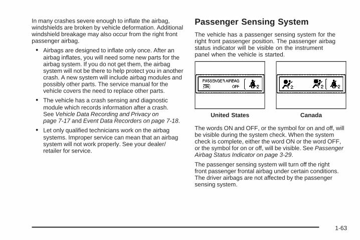
Passenger Sensing SystemThe vehicle has a passenger sensing system for theright front passenger position. The passenger airbagstatus indicator will be visible on the instrumentpanel when the vehicle is started.
The words ON and OFF, or the symbol for on and off, willbe visible during the system check. When the systemcheck is complete, either the word ON or the word OFF,or the symbol for on or off, will be visible. See PassengerAirbag Status Indicator on page 3-29.
The passenger sensing system will turn off the rightfront passenger frontal airbag under certain conditions.The driver airbags are not affected by the passengersensing system.
United States Canada
1-63

The passenger sensing system works with sensors thatare part of the right front passenger seat. The sensorsare designed to detect the presence of a properly-seatedoccupant and determine if the right front passengerfrontal airbag should be enabled (may inflate) or not.
According to accident statistics, children are safer whenproperly secured in a rear seat in the correct childrestraint for their weight and size.
We recommend that children be secured in a rear seat,including: an infant or a child riding in a rear-facingchild restraint; a child riding in a forward-facing childseat; an older child riding in a booster seat; and children,who are large enough, using safety belts.
A label on your sun visor says, “Never put a rear-facingchild seat in the front.” This is because the risk to therear-facing child is so great, if the airbag deploys.
{CAUTION:
A child in a rear-facing child restraint can beseriously injured or killed if the right front passengerairbag inflates. This is because the back of therear-facing child restraint would be very close to theinflating airbag. A child in a forward-facing childrestraint can be seriously injured or killed if the rightfront passenger airbag inflates and the passengerseat is in a forward position.
Even if the passenger sensing system has turnedoff the right front passenger frontal airbag, nosystem is fail-safe. No one can guarantee thatan airbag will not deploy under some unusualcircumstance, even though the airbag is turned off.
Secure rear-facing child restraints in a rearseat, even if the airbag is off. If you secure aforward-facing child restraint in the right front seat,always move the front passenger seat as far backas it will go. It is better to secure the child restraint ina rear seat.
1-64

If your vehicle does not have a rear seat that willaccommodate a rear-facing child restraint, werecommend that rear-facing child restraints not betransported in your vehicle, even if the airbag is off.
The passenger sensing system is designed to turn offthe right front passenger frontal airbag if:
• The right front passenger seat is unoccupied.
• The system determines that an infant is present ina rear-facing infant seat.
• The system determines that a small child is presentin a child restraint.
• The system determines that a small child is presentin a booster seat.
• A right front passenger takes his/her weight off ofthe seat for a period of time.
• The right front passenger seat is occupied by asmaller person, such as a child who has outgrownchild restraints.
• Or, if there is a critical problem with the airbagsystem or the passenger sensing system.
When the passenger sensing system has turned off theright front passenger frontal airbag, the off indicatorwill light and stay lit to remind you that the airbag is off.See Passenger Airbag Status Indicator on page 3-29.
The passenger sensing system is designed to turn on(may inflate) the right front passenger frontal airbaganytime the system senses that a person of adult sizeis sitting properly in the right front passenger seat.
When the passenger sensing system has allowed theairbag to be enabled, the on indicator will light and staylit to remind you that the airbag is active.
For some children who have outgrown child restraintsand for very small adults, the passenger sensing systemmay or may not turn off the right front passenger frontalairbag, depending upon the person’s seating postureand body build. Everyone in your vehicle who hasoutgrown child restraints should wear a safety beltproperly — whether or not there is an airbag for thatperson.
{CAUTION:
If the airbag readiness light ever comes on andstays on, it means that something may be wrongwith the airbag system. To help avoid injury toyourself or others, have the vehicle serviced rightaway. See Airbag Readiness Light on page 3-28for more information, including important safetyinformation.
1-65

If the On Indicator is Lit for a ChildRestraintIf a child restraint has been installed and the onindicator is lit:1. Turn the vehicle off.2. Remove the child restraint from the vehicle.3. Remove any additional items from the seat such as
blankets, cushions, seat covers, seat heaters, orseat massagers.
4. Reinstall the child restraint following the directionsprovided by the child restraint manufacturer andrefer to Securing a Child Restraint in the Right FrontSeat Position on page 1-52.
5. If, after reinstalling the child restraint and restartingthe vehicle, the on indicator is still lit, turn the vehicleoff. Then slightly recline the vehicle seatback andadjust the seat cushion, if adjustable, to make surethat the vehicle seatback is not pushing the childrestraint into the seat cushion.Also make sure the child restraint is not trappedunder the vehicle head restraint. If this happens,adjust the head restraint. See Head Restraintson page 1-7.
6. Restart the vehicle.If the on indicator is still lit, secure the child restraintin a rear seat position in the vehicle and checkwith your dealer/retailer.
If the Off Indicator is Lit for anAdult-Size Occupant
If a person of adult-size is sitting in the right frontpassenger seat, but the off indicator is lit, it could bebecause that person is not sitting properly in the seat.
1-66

If this happens, use the following steps to allow thesystem to detect that person and enable the right frontpassenger frontal airbag:
1. Turn the vehicle off.
2. Remove any additional material from the seat, suchas blankets, cushions, seat covers, seat heaters, orseat massagers.
3. Place the seatback in the fully upright position.
4. Have the person sit upright in the seat, centered onthe seat cushion, with legs comfortably extended.
5. Restart the vehicle and have the person remain inthis position for two to three minutes after the onindicator is lit.
Additional Factors Affecting SystemOperationSafety belts help keep the passenger in position on theseat during vehicle maneuvers and braking, which helpsthe passenger sensing system maintain the passengerairbag status. See “Safety Belts” and “Child Restraints” inthe Index for additional information about the importanceof proper restraint use.
A thick layer of additional material, such as a blanket orcushion, or aftermarket equipment such as seat covers,seat heaters, and seat massagers can affect how wellthe passenger sensing system operates. We recommendthat you not use seat covers or other aftermarketequipment except when approved by GM for your specificvehicle. See Adding Equipment to Your Airbag-EquippedVehicle on page 1-68 for more information aboutmodifications that can affect how the system operates.
{CAUTION:
Stowing of articles under the passenger seat orbetween the passenger seat cushion and seatbackmay interfere with the proper operation of thepassenger sensing system.
1-67

Servicing Your Airbag-EquippedVehicleAirbags affect how the vehicle should be serviced.There are parts of the airbag system in several placesaround the vehicle. Your dealer/retailer and theservice manual have information about servicing thevehicle and the airbag system. To purchase a servicemanual, see Service Publications Ordering Informationon page 7-16.
{CAUTION:
For up to 10 seconds after the ignition is turned offand the battery is disconnected, an airbag can stillinflate during improper service. You can be injuredif you are close to an airbag when it inflates. Avoidyellow connectors. They are probably part of theairbag system. Be sure to follow proper serviceprocedures, and make sure the person performingwork for you is qualified to do so.
Adding Equipment to YourAirbag-Equipped Vehicle
Q: Is there anything I might add to or changeabout the vehicle that could keep the airbagsfrom working properly?
A: Yes. If you add things that change the vehicle’sframe, bumper system, height, front end or sidesheet metal, they may keep the airbag system fromworking properly. Changing or moving any partsof the front seats, safety belts, the airbag sensingand diagnostic module, steering wheel, instrumentpanel, roof-rail airbag modules, ceiling headlineror pillar garnish trim, overhead console, frontsensors, side impact sensors, rollover sensormodule, or airbag wiring can affect the operationof the airbag system.
In addition, the vehicle has a passenger sensingsystem for the right front passenger position, whichincludes sensors that are part of the passenger seat.
1-68

The passenger sensing system may not operateproperly if the original seat trim is replaced withnon-GM covers, upholstery or trim, or with GMcovers, upholstery or trim designed for a differentvehicle. Any object, such as an aftermarket seatheater or a comfort enhancing pad or device,installed under or on top of the seat fabric, could alsointerfere with the operation of the passenger sensingsystem. This could either prevent proper deploymentof the passenger airbag(s) or prevent the passengersensing system from properly turning off thepassenger airbag(s). See Passenger SensingSystem on page 1-63.
If you have any questions, call Customer Assistance.The phone numbers and addresses for CustomerAssistance are in Step Two of the CustomerSatisfaction Procedure in this manual. See CustomerSatisfaction Procedure on page 7-2.
If the vehicle has rollover roof-rail airbags, seeDifferent Size Tires and Wheels on page 5-66 foradditional important information.
Q: Because I have a disability, I have to get myvehicle modified. How can I find out whetherthis will affect my airbag system?
A: If you have questions, call Customer Assistance.The phone numbers and addresses for CustomerAssistance are in Step Two of the CustomerSatisfaction Procedure in this manual. SeeCustomer Satisfaction Procedure on page 7-2.
In addition, your dealer/retailer and the service manualhave information about the location of the airbag sensors,sensing and diagnostic module and airbag wiring.
1-69

Restraint System Check
Checking the Restraint Systems
Safety BeltsNow and then, check that the safety belt reminderlight, safety belts, buckles, latch plates, retractors,and anchorages are all working properly.
Look for any other loose or damaged safety belt systemparts that might keep a safety belt system from doingits job. See your dealer/retailer to have it repaired.Torn or frayed safety belts may not protect youin a crash. They can rip apart under impact forces.If a belt is torn or frayed, get a new one right away.
Make sure the safety belt reminder light is working.See Safety Belt Reminders on page 3-27 for moreinformation.
Keep safety belts clean and dry. See Care of SafetyBelts on page 5-85.
AirbagsThe airbag system does not need regularly scheduledmaintenance or replacement. Make sure the airbagreadiness light is working. See Airbag Readiness Lighton page 3-28 for more information.
Notice: If an airbag covering is damaged, opened,or broken, the airbag may not work properly. Do notopen or break the airbag coverings. If there are anyopened or broken airbag covers, have the airbagcovering and/or airbag module replaced. For thelocation of the airbag modules, see What Makes anAirbag Inflate? on page 1-61. See your dealer/retailerfor service.
1-70

Replacing Restraint System PartsAfter a Crash
{CAUTION:
A crash can damage the restraint systems in yourvehicle. A damaged restraint system may notproperly protect the person using it, resulting inserious injury or even death in a crash. To helpmake sure your restraint systems are workingproperly after a crash, have them inspected andany necessary replacements made as soon aspossible.
If the vehicle has been in a crash, do you need newsafety belts or LATCH system (if equipped) parts?
After a very minor crash, nothing may be necessary.But the safety belt assemblies that were used during anycrash may have been stressed or damaged. See yourdealer/retailer to have the safety belt assembliesinspected or replaced.
If the vehicle has the LATCH system and it was beingused during a crash, you may need new LATCH systemparts.
New parts and repairs may be necessary even if thesafety belt or LATCH system (if equipped), was not beingused at the time of the crash.
If an airbag inflates, you will need to replace airbagsystem parts. See the part on the airbag system earlierin this section.
Have the safety belt pretensioners checked if the vehiclehas been in a crash, if the airbag readiness light stayson after the vehicle is started, or while you are driving.See Airbag Readiness Light on page 3-28.
1-71

✍ NOTES
1-72
Keys ...............................................................2-3Remote Keyless Entry (RKE) System ................2-4Remote Keyless Entry (RKE) System
Operation ...................................................2-5Remote Vehicle Start ......................................2-7
Doors and Locks ............................................2-10Door Locks ..................................................2-10Power Door Locks ........................................2-10Delayed Locking ...........................................2-10Programmable Automatic Door Locks ..............2-11Rear Door Security Locks ..............................2-11Lockout Protection ........................................2-12Liftgate ........................................................2-12
Windows ........................................................2-14Power Windows ............................................2-15Sun Visors ...................................................2-16
Theft-Deterrent Systems ..................................2-16Content Theft-Deterrent .................................2-17PASS-Key® III+ Electronic Immobilizer .............2-17PASS-Key® III+ Electronic Immobilizer
Operation .................................................2-18
Starting and Operating Your Vehicle ................2-19New Vehicle Break-In ....................................2-19Ignition Positions ..........................................2-20Retained Accessory Power (RAP) ...................2-21Starting the Engine .......................................2-22Engine Coolant Heater ..................................2-23Automatic Transmission Operation
(3.4L V6 with 5-Speed) ..............................2-24Automatic Transmission Operation
(3.6L V6 with 6-Speed) ..............................2-27Parking Brake ..............................................2-31Shifting Into Park ..........................................2-32Shifting Out of Park ......................................2-33Parking Over Things That Burn .......................2-34Engine Exhaust ............................................2-35Running the Vehicle While Parked ..................2-36
Mirrors ...........................................................2-36Manual Rearview Mirror .................................2-36Automatic Dimming Rearview Mirror ................2-37Outside Power Mirrors ...................................2-37Outside Convex Mirrors .................................2-38
Section 2 Features and Controls
2-1

OnStar® System .............................................2-38Storage Areas ................................................2-42
Glove Box ...................................................2-42Cupholders ..................................................2-42Center Console Storage .................................2-42Luggage Carrier ...........................................2-42
Rear Compartment Storage Panel/Cover ..........2-44Rear Seat Armrest ........................................2-45Table ..........................................................2-46Convenience Net ..........................................2-47
Sunroof .........................................................2-47
Section 2 Features and Controls
2-2

Keys
{CAUTION:
Leaving children in a vehicle with the ignition keyis dangerous for many reasons, children or otherscould be badly injured or even killed. They couldoperate the power windows or other controls oreven make the vehicle move. The windows willfunction with the keys in the ignition and childrencould be seriously injured or killed if caught in thepath of a closing window. Do not leave the keys ina vehicle with children.
The key can be used for the ignition and all locks.
The key has a bar-coded key tag that the dealer/retaileror qualified locksmith can use to make new keys. Storethis information in a safe place, not in your vehicle.
Notice: If you ever lock your keys in the vehicle,you may have to damage the vehicle to get in.Be sure you have spare keys.
If you are locked out of your vehicle, contact RoadsideAssistance. See Roadside Assistance Program onpage 7-7 for more information.
2-3

Remote Keyless Entry (RKE)SystemIf this vehicle has the Remote Keyless Entry (RKE)system, it operates on a radio frequency subject toFederal Communications Commission (FCC) Rulesand with Industry Canada.
This device complies with Part 15 of the FCC Rules.Operation is subject to the following two conditions:
1. This device may not cause interference.
2. This device must accept any interference received,including interference that may cause undesiredoperation of the device.
This device complies with RSS-210 of Industry Canada.Operation is subject to the following two conditions:
1. This device may not cause interference.
2. This device must accept any interference received,including interference that may cause undesiredoperation of the device.
Changes or modifications to this system by other thanan authorized service facility could void authorization touse this equipment.
If there is a decrease in the RKE operating range, try this:
• Check the distance. The transmitter may be too farfrom the vehicle. Stand closer during rainy or snowyweather.
• Check the location. Other vehicles or objects may beblocking the signal. Take a few steps to the left orright, hold the transmitter higher, and try again.
• Check the transmitter’s battery. See “BatteryReplacement” later in this section.
• If the transmitter is still not working correctly, seeyour dealer/retailer or a qualified technician forservice.
2-4

Remote Keyless Entry (RKE)System OperationThe Remote Keyless Entry (RKE) transmitter functionswork up to 195 feet (60 m) away from the vehicle.There are other conditions which can affect theperformance of the transmitter. See Remote KeylessEntry (RKE) System on page 2-4.
/ (Remote Vehicle Start): For vehicles with thisfeature, press to start the engine from outside the vehicleusing the RKE transmitter. See Remote Vehicle Start onpage 2-7 for additional information.
Q (Lock): Press to lock the doors and liftgate. If enabledthrough the Driver Information Center (DIC), the parkinglamps flash once to indicate locking has occurred. Ifenabled through the DIC, the horn chirps when Q ispressed again within five seconds. See DIC VehiclePersonalization on page 3-57 for additional information.
Pressing Q may arm the content theft-deterrent system.See Content Theft-Deterrent on page 2-17.
K (Unlock): Press once to unlock the driver door.If K is pressed again within five seconds, all remainingdoors and the liftgate unlock. The interior lamps come onand stay on for 20 seconds or until the ignition is turnedon. If enabled through the DIC, the parking lamps flashtwice to indicate unlocking has occurred. See DIC VehiclePersonalization on page 3-57.
Pressing K on the RKE transmitter disarms the contenttheft-deterrent system. See Content Theft-Deterrent onpage 2-17.
L (Vehicle Locator/Panic Alarm): Press and releaseto locate the vehicle. The turn signal lamps flash andthe horn sounds three times.
With Remote StartShown, Without Remote
Start Similar
2-5

Press and hold L for more than two seconds to activatethe panic alarm. The turn signal lamps flash and the hornsounds repeatedly for 30 seconds. The alarm turns offwhen the ignition is moved to ON/RUN or L is pressedagain. The ignition must be in LOCK/OFF for the panicalarm to work.
The RKE transmitter is used to arm/disarm the contenttheft-deterrent system. The theft-deterrent system canbe programmed to three different modes. See ContentTheft-Deterrent on page 2-17.
If you accidentally set off the alarm when entering orexiting the vehicle, press Q or K once or L twiceto turn it off.
Programming Transmitters to theVehicleOnly RKE transmitters programmed to the vehicle willwork. If a transmitter is lost or stolen, a replacementcan be purchased and programmed through yourdealer/retailer. When the replacement transmitter isprogrammed to the vehicle, all remaining transmittersmust also be programmed. Any lost or stolen transmittersno longer work once the new transmitter is programmed.Each vehicle can have up to four transmittersprogrammed to it. See “Learn Remote Key” underDIC Operation and Displays on page 3-42.
Battery Replacement
Notice: When replacing the battery, do not touchany of the circuitry on the transmitter. Staticfrom your body could damage the transmitter.
To replace the battery:
1. Separate the transmitter with a flat, thin objectinserted into the notch on the side.
2. Remove the old battery. Do not use a metal object.
3. Insert the new battery, positive side facing down.Replace with a CR2032 or equivalent battery.
4. Snap the transmitter back together.
2-6

Remote Vehicle StartYour vehicle may have the remote start feature.This feature allows you to start the engine from outsidethe vehicle. See “REMOTE START” under DIC VehiclePersonalization on page 3-57 for instructions on howto enable and disable this feature.
During a remote start, the climate control system willturn on at the fan, temperature, and mode settings thevehicle was set to when the vehicle was last turnedoff. The rear window defogger will also turn on.
If your vehicle has heated seats, they may turn on duringcolder outside temperatures and will shut off when thekey is turned to ON/RUN. You may not notice an increasein seat surface temperature until the seat is occupied fora short period of time.
Laws in some local communities may restrict the useof remote starters. For example, some laws may requirea person using remote start to have the vehicle inview when doing so. Check local regulations forany requirements on remote starting of vehicles.
If your vehicle is low on fuel, do not use the remotestart feature. The vehicle may run out of fuel.
If your vehicle has the remote start feature, the RKEtransmitter functions will have an increased rangeof operation. However, the range may be less whilethe vehicle is running.
There are other conditions which can affect theperformance of the transmitter, see Remote KeylessEntry (RKE) System on page 2-4 for additionalinformation.
/ (Remote Vehicle Start): This button will be on theRKE transmitter if you have remote start.
To start the engine using the remote start feature:
1. Aim the RKE transmitter, that has a remote vehiclestart button, at the vehicle.
2. Press and release the transmitter’s lock button, thenimmediately press and hold the remote vehicle startbutton. Hold the remote start button until the vehicle’sturn signal lamps flash, or for at least four secondsif the vehicle’s lights are not visible. The vehicle’sdoors will be locked.Pressing the remote start button again after thevehicle has started will turn off the ignition.When the vehicle’s engine starts, the parking lampswill turn on and remain on while the engine isrunning.
2-7

3. To extend the engine run time by 10 minutes, repeatSteps 1 and 2 while the engine is still running.The engine run time can only be extended if it isthe first remote start since the vehicle has beendriven. Remote start can be extended one time.If the remote start procedure is used again beforethe first 10 minute time frame has ended, thefirst 10 minutes will immediately expire and thesecond 10 minute time frame will start.For example, if the lock button and then the remotestart buttons are pressed again after the vehiclehas been running for five minutes, 10 minutes areadded, allowing the engine to run for 15 minutes.
4. After entering the vehicle during a remote start,insert and turn the key to ON/RUN to drive thevehicle.After a remote start, the engine will automaticallyshut off after 10 minutes unless a time extensionhas been done or the vehicle’s key is inserted intothe ignition switch and turned to ON/RUN.
A maximum of two remote starts or remote startattempts are allowed between ignition cycles.
After your vehicle’s engine has been started two timesusing the remote start button, the vehicle’s ignitionswitch must be turned to ON/RUN and then back toLOCK/OFF using the key before the remote startprocedure can be used again.
To manually shut off the engine after a remote start, doany of the following:
• Aim the RKE transmitter at the vehicle and pressthe remote start button until the parking lampsturn off.
• Turn on the hazard warning flashers.
• Insert the vehicle’s key into the ignition switchand turn the switch to ON/RUN and then backto LOCK/OFF.
2-8

The remote vehicle start feature will not operate if anyof the following occur:
• The vehicle’s key is in the ignition.
• The vehicle’s hood, liftgate or doors are not closed.
• The hazard warning flashers are on.
• There is an emission control system malfunction.
• The engine coolant temperature is too high.
• The oil pressure is low.
• Two remote vehicle starts have already been used.The maximum number of remote starts or remotestart attempts between ignition cycles with the keyis two.
• The remote start feature may be disabled.The system may be enabled or disabled throughthe DIC. See “REMOTE START” under DICVehicle Personalization on page 3-57 foradditional information.
Vehicles that have the remote vehicle start featureare shipped from the factory with the remote vehiclestart system enabled.
Remote Start ReadyIf your vehicle does not have the remote vehicle startfeature, it may have the remote start ready feature.This feature allows your dealer/retailer to add themanufacturer’s remote vehicle start feature.
If your vehicle has the remote start ready feature, yourRKE transmitter will have extended range that will allowyou to lock or unlock your vehicle from approximately195 feet (60 m) away.
See your dealer/retailer if you would like to add themanufacturer’s remote vehicle start feature to yourvehicle.
2-9

Doors and Locks
Door Locks
{CAUTION:
Unlocked doors can be dangerous.• Passengers, especially children, can easily
open the doors and fall out of a moving vehicle.When a door is locked, the handle will not openit. The chance of being thrown out of thevehicle in a crash is increased if the doors arenot locked. So, all passengers should wearsafety belts properly and the doors should belocked whenever the vehicle is driven.
• Young children who get into unlocked vehiclesmay be unable to get out. A child can beovercome by extreme heat and can sufferpermanent injuries or even death from heatstroke. Always lock the vehicle wheneverleaving it.
• Outsiders can easily enter through an unlockeddoor when you slow down or stop your vehicle.Locking your doors can help prevent this fromhappening.
To lock or unlock a door, use the key from the outsideor the door lock from the inside.
Power Door LocksThe power door lock switches are located on thedriver’s and front passenger’s doors.
K (Unlock): To unlock the doors, press the unlocksymbol.
Q (Lock): Remove the key and press the lock symbolto lock all of the doors.
Delayed LockingA chime will sound three times to indicate a door orliftgate is open when you try to lock the doors with thepower door lock switch. The doors will not lock, and thetheft-deterrent system will not arm until all the doorsare closed and ten seconds have passed.
The delayed locking feature can be programmed throughthe Driver Information Center (DIC). See DIC VehiclePersonalization on page 3-57.
See also Remote Keyless Entry (RKE) SystemOperation on page 2-5.
2-10

Programmable Automatic DoorLocksYour vehicle has an automatic lock/unlock feature whichenables you to program the power door locks throughthe Driver Information Center (DIC). See DIC VehiclePersonalization on page 3-57 for more informationon DIC programming.
Rear Door Security LocksYour vehicle has rear door security locks that preventpassengers from opening the rear doors from the inside.
The rear door security locksare located on the insideedge of each rear door.You must open the reardoors to access them.
To set the security locks, do the following:
1. Insert the key into the lock above the rear doorsecurity lock label and turn it to the horizontalposition.
2. Close the door.
3. Repeat the steps for the other rear door.
To open a rear door while the security lock is on, do thefollowing:
1. Unlock the door using the remote keyless entrytransmitter, the front door power lock switch, orthe rear door manual lock.
2. Open the door from the outside.
To cancel the rear door security lock, do the following:
1. Unlock the door and open it from the outside.
2. Insert the key into the slot next to the rear doorsecurity lock label and turn it to the verticalposition.
3. Repeat the steps for the other lock.
2-11

Lockout ProtectionIf you press the power door lock switch when the key isin the ignition and any door is open, all the doors willlock and only the driver’s door will unlock. Be sureto remove the key from the ignition when lockingyour vehicle.
If the keyless entry transmitter is used to lock thedoors and the key is in the ignition, a chime will soundthree times. All passenger doors will lock, but the driver’sdoor will remain unlocked.
Liftgate
{CAUTION:
It can be dangerous to drive with the liftgate orliftglass open because carbon monoxide (CO) gascan come into your vehicle. You cannot see orsmell CO. It can cause unconsciousness and evendeath. If you must drive with the liftgate open or if
CAUTION: (Continued)
CAUTION: (Continued)
electrical wiring or other cable connections mustpass through the seal between the body and theliftgate or liftglass:
• Make sure all other windows are shut.• Turn the fan on your climate control system to
its highest speed and select the control settingthat will force outside air into your vehicle.See “Climate Control System” in the Index.
• If you have air outlets on or under theinstrument panel, open them all the way.See Engine Exhaust on page 2-35.
To unlock the liftgate, press the unlock button on theRemote Keyless Entry (RKE) transmitter twice or usethe power door lock switch.
To lock the liftgate, press the lock button on theRKE transmitter or use the power door lock switch.The liftgate does not have a key lock cylinder.
To open the liftgate, press the touchpad centered onthe underside of the liftgate handle and pull up.
When closing the liftgate, use the molded handles topull the liftgate down. Push the liftgate closed untilit latches.
2-12

Liftgate Operation with Loss of PowerThe liftgate is equipped with an electric latch. If thebattery is disconnected or has low voltage, the liftgatewill not open.
To open the liftgate if thishappens, remove theinterior trim plug located atthe base of the liftgatefrom inside the vehicle.
Use a tool to push theservice release leverlocated on the latch untilyou hear or feel the gaterelease.
The liftgate can now be opened and closed manually.You will need to use this procedure to open theliftgate until the power is restored.
2-13

Windows
{CAUTION:
Leaving children, helpless adults, or pets in avehicle with the windows closed is dangerous.They can be overcome by the extreme heat andsuffer permanent injuries or even death from heatstroke. Never leave a child, a helpless adult, or apet alone in a vehicle, especially with the windowsclosed in warm or hot weather.
2-14

Power Windows
{CAUTION:
Leaving children in a vehicle with the keys isdangerous for many reasons, children or otherscould be badly injured or even killed. They couldoperate the power windows or other controls oreven make the vehicle move. The windows willfunction and they could be seriously injured orkilled if caught in the path of a closing window.Do not leave keys in a vehicle with children.
When there are children in the rear seat use thewindow lockout button to prevent unintentionaloperation of the windows.
The window switches for all doors are located on thecenter console. A window switch for each rear window islocated on each rear door.
To open or close a window press or pull the switch.
The power windows operate when the ignition isin ON/RUN, ACC/ACCESSORY, or while in RetainedAccessory Power (RAP). See Retained AccessoryPower (RAP) on page 2-21.
2-15

Express-Down WindowThe driver’s window switch has an express-downfeature that allows the window to be lowered withoutholding the switch. Press the switch part way, andthe driver’s window opens a small amount. Press theswitch down all the way, release it, and the window goesdown automatically.
To stop the window while it is lowering, press andrelease the switch.
Window Lockout
o (Window Lockout): Your vehicle has a lockoutfeature to prevent rear seat passengers from operatingthe windows. Press the lockout button, located withthe power window switches, to turn the feature on andoff. The switch has a light that comes on when theswitch is active.
Sun VisorsTo block out glare, swing the sun visor down. You canalso detach the driver’s sun visor from the centermount and slide it along the rod from side-to-side forgreater coverage.
Visor Vanity MirrorsYour vehicle has covered visor vanity mirrors on boththe driver’s and passenger’s side.
Theft-Deterrent SystemsVehicle theft is big business, especially in some cities.This vehicle has theft-deterrent features, however,they do not make it impossible to steal.
2-16

Content Theft-DeterrentYour vehicle has a content theft-deterrent alarm system.To activate the theft-deterrent system:
1. Open the door.
2. Lock the door with the power door lock switchor the Remote Keyless Entry (RKE) transmitter.If you are using the RKE transmitter, the doordoes not need to be open.
3. Close all doors.The key must be removed from the ignition to armthe system.
If the theft-deterrent system is activated and a door orthe liftgate is opened without using the RKE transmitter, a10 second pre-alarm will occur, and the security light willflash. The horn will sound rapidly for 10 seconds. If youdo not press unlock on the RKE transmitter or insertthe key in the ignition and turn if from the LOCK/OFFposition, the alarm will go off. The horn will sound andthe headlamps will flash for 30 seconds.
After the alarm has sounded for 30 seconds, the systemwill re-arm itself automatically.
To disarm the theft-deterrent system, do one of thefollowing:1. Unlock the doors with the RKE transmitter.2. Insert the key in the ignition and turn it from the
LOCK/OFF position.
PASS-Key® III+ ElectronicImmobilizerThe PASS-Key III+ system operates on a radiofrequency subject to Federal CommunicationsCommission (FCC) Rules and with Industry Canada.
This device complies with Part 15 of the FCC Rules.Operation is subject to the following two conditions:
1. This device may not cause harmful interference.
2. This device must accept any interference received,including interference that may cause undesiredoperation.
This device complies with RSS-210 of Industry Canada.Operation is subject to the following two conditions:
1. This device may not cause interference.
2. This device must accept any interference received,including interference that may cause undesiredoperation of the device.
Changes or modifications to this system by other thanan authorized service facility could void authorization touse this equipment.
PASS-Key III+ uses a radio frequency transponder inthe key that matches a decoder in the vehicle.
2-17

PASS-Key® III+ ElectronicImmobilizer OperationYour vehicle has PASS-Key® III+ (PersonalizedAutomotive Security System) theft-deterrent system.PASS-Key® III+ is a passive theft-deterrent system.
The system is automatically armed when the keyis removed from the ignition.
The system is automatically disarmed when the key isturned to ON/RUN, ACC/ACCESSORY or START fromthe LOCK/OFF position.
You do not have to manually arm or disarm the system.
The security light will come on if there is a problemwith arming or disarming the theft-deterrent system.
When the PASS-Key® III+ system senses that someoneis using the wrong key, it prevents the vehicle fromstarting. Anyone using a trial-and-error method to startthe vehicle will be discouraged because of the highnumber of electrical key codes.
If the engine does not start and the security light onthe instrument panel comes on when trying to start thevehicle, there may be a problem with your theft-deterrentsystem. Turn the ignition off and try again.
If the engine still does not start, and the key appears tobe undamaged, try another ignition key. At this time,you may also want to check the fuse, see Fusesand Circuit Breakers on page 5-91. If the engine stilldoes not start with the other key, your vehicle needsservice. If your vehicle does start, the first key may befaulty. See your dealer/retailer who can service thePASS-Key® III+ to have a new key made. In anemergency, contact Roadside Assistance.
It is possible for the PASS-Key® III+ decoder to “learn”the transponder value of a new or replacement key. Up tonine additional keys may be programmed for the vehicle.The following procedure is for programming additionalkeys only. If all the currently programmed keys are lostor do not operate, you must see your dealer/retailer or alocksmith who can service PASS-Key® III+ to have keysmade and programmed to the system.
2-18

See your dealer/retailer or a locksmith who can servicePASS-Key® III+ to get a new key blank that is cutexactly as the ignition key that operates the system.
To program the new additional key:
1. Verify that the new key has a 1 stamped on it.
2. Insert the original, already programmed, key in theignition and start the engine. If the engine will notstart, see your dealer/retailer for service.
3. After the engine has started, turn the key toLOCK/OFF, and remove the key.
4. Insert the new key to be programmed and turnit to the ON/RUN position within five seconds ofremoving the original key.The security light will turn off once the key hasbeen programmed.
5. Repeat Steps 1 through 4 if additional keys are tobe programmed.
If you lose or damage your PASS-Key® III+ key, seeyour dealer/retailer or a locksmith who can servicePASS-Key® III+ to have a new key made.
Do not leave the key or device that disarms ordeactivates the theft deterrent system in the vehicle.
Starting and Operating YourVehicle
New Vehicle Break-InNotice: The vehicle does not need an elaboratebreak-in. But it will perform better in the long run ifyou follow these guidelines:
• Do not drive at any one constant speed, fast orslow, for the first 500 miles (805 km). Do notmake full-throttle starts. Avoid downshifting tobrake or slow the vehicle.
• Avoid making hard stops for the first 200 miles(322 km) or so. During this time the new brakelinings are not yet broken in. Hard stopswith new linings can mean premature wear andearlier replacement. Follow this breaking-inguideline every time you get new brake linings.
• Do not tow a trailer during break-in. See Towinga Trailer on page 4-33 for the trailer towingcapabilities of your vehicle and moreinformation.
Following break-in, engine speed and load can begradually increased.
2-19
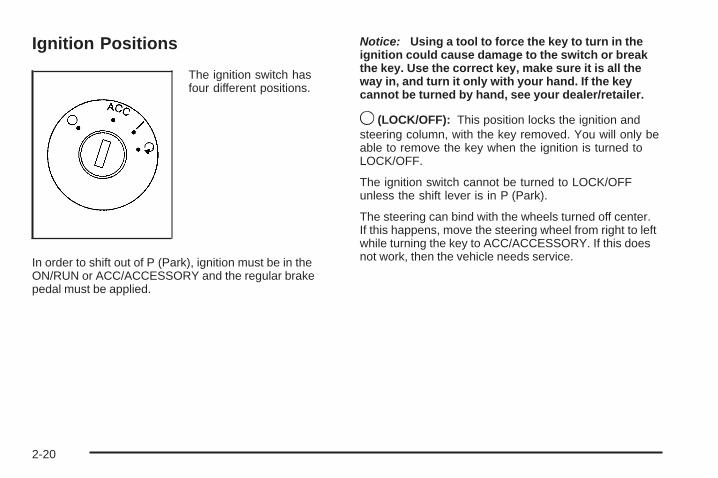
Ignition Positions
The ignition switch hasfour different positions.
In order to shift out of P (Park), ignition must be in theON/RUN or ACC/ACCESSORY and the regular brakepedal must be applied.
Notice: Using a tool to force the key to turn in theignition could cause damage to the switch or breakthe key. Use the correct key, make sure it is all theway in, and turn it only with your hand. If the keycannot be turned by hand, see your dealer/retailer.
9 (LOCK/OFF): This position locks the ignition andsteering column, with the key removed. You will only beable to remove the key when the ignition is turned toLOCK/OFF.
The ignition switch cannot be turned to LOCK/OFFunless the shift lever is in P (Park).
The steering can bind with the wheels turned off center.If this happens, move the steering wheel from right to leftwhile turning the key to ACC/ACCESSORY. If this doesnot work, then the vehicle needs service.
2-20

ACC (ACC/ACCESSORY): This is the position in whichyou can operate some electrical accessories.
R (ON/RUN): This position can be used to operate theelectrical accessories and to display some instrumentpanel cluster warning and indicator lights. The switchstays in this position when the engine is running. If youleave the key in the ACC/ACCESSORY or ON/RUNposition with the engine off, the battery could be drained.You may not be able to start the vehicle if the battery isallowed to drain for an extended period of time.
/ (START): This is the position that starts the engine.When the engine starts, release the key. The ignitionswitch returns to ON/RUN for driving.
Retained Accessory Power (RAP)These vehicle accessories can be used for up to10 minutes after the engine is turned off:
• Audio System
• Power Windows
• Sunroof (if equipped)
Power to these accessories will continue to operate forup to 10 minutes or until the driver door is opened.
All these features will work when the key is in ON/RUNor ACC/ACCESSORY.
2-21

Starting the EngineMove the shift lever to P (Park) or N (Neutral). Theengine will not start in any other position. To restartthe engine when the vehicle is already moving, useN (Neutral) only.
Notice: Do not try to shift to P (Park) if thevehicle is moving. If you do, you could damagethe transmission. Shift to P (Park) only whenthe vehicle is stopped.
Starting Procedure1. With your foot off the accelerator pedal, turn the
ignition to START. When the engine starts, let go ofthe key. The idle speed will slow down as the enginewarms. Do not race the engine immediately afterstarting it. Operate the engine and transmissiongently to allow the oil to warm up and lubricate allmoving parts.The vehicle has a Computer-Controlled CrankingSystem. This feature assists in starting the engineand protects components. If the ignition key is turnedto the START position, and then released when theengine begins cranking, the engine will continuecranking for a few seconds or until the vehicle starts.
If the engine does not start and the key is held inSTART, cranking will be stopped after 15 seconds toprevent cranking motor damage. To prevent geardamage, this system also prevents cranking if theengine is already running. Engine cranking can bestopped by turning the ignition switch to the ACC/ACCESSORY or LOCK/OFF position.
Notice: Cranking the engine for long periods oftime, by returning the key to the START positionimmediately after cranking has ended, can overheatand damage the cranking motor, and drain thebattery. Wait at least 15 seconds between each try,to let the cranking motor cool down.
2. If the engine does not start after 5-10 seconds,especially in very cold weather (below 0°F or −18°C),it could be flooded with too much gasoline. Trypushing the accelerator pedal all the way to the floorand holding it there as you hold the key in STARTfor up to a maximum of 15 seconds. Wait at least15 seconds between each try, to allow the crankingmotor to cool down. When the engine starts, let go ofthe key and accelerator. If the vehicle starts brieflybut then stops again, repeat these steps. This clearsthe extra gasoline from the engine. Do not race theengine immediately after starting it. Operate theengine and transmission gently until the oil warmsup and lubricates all moving parts.
2-22
Notice: The engine is designed to work with theelectronics in the vehicle. If you add electrical partsor accessories, you could change the way the engineoperates. Before adding electrical equipment, checkwith your dealer/retailer. If you do not, the enginemight not perform properly. Any resulting damagewould not be covered by the vehicle warranty.
Engine Coolant HeaterThe engine coolant heater can provide easier startingand better fuel economy during engine warm-up in coldweather conditions at or below 0°F (−18°C). Vehicles withan engine coolant heater should be plugged in at leastfour hours before starting. An internal thermostat inthe plug-end of the cord may exist which will preventengine coolant heater operation at temperatures above0°F (−18°C).
To Use the Engine Coolant Heater1. Turn off the engine.
2. Open the hood and unwrap the electrical cord.The cord is located on the passenger side of theengine compartment, near the radiator.
3. Plug it into a normal, grounded 110-volt AC outlet.
{CAUTION:
Plugging the cord into an ungrounded outlet couldcause an electrical shock. Also, the wrong kind ofextension cord could overheat and cause a fire.You could be seriously injured. Plug the cord intoa properly grounded three-prong 110-volt ACoutlet. If the cord will not reach, use a heavy-dutythree-prong extension cord rated for at least15 amps.
4. Before starting the engine, be sure to unplug andstore the cord as it was before to keep it awayfrom moving engine parts, to prevent damage.
The length of time the heater should remain plugged independs on several factors. Ask a dealer/retailer inthe area where you will be parking the vehicle for thebest advice on this.
2-23

Automatic Transmission Operation(3.4L V6 with 5-Speed)The shift lever is located on the center console. Whenyou change gears, the different shift positions will displayon the instrument panel cluster.
There are several different positions for the automatictransmission.
P (Park): This position locks the front wheels. It isthe best position to use when you start the enginebecause the vehicle cannot move easily.
{CAUTION:
It is dangerous to get out of the vehicle if the shiftlever is not fully in P (Park) with the parking brakefirmly set. The vehicle can roll.
Do not leave the vehicle when the engine isrunning unless you have to. If you have left theengine running, the vehicle can move suddenly.You or others could be injured. To be sure thevehicle will not move, even when you are on fairlylevel ground, always set the parking brake andmove the shift lever to P (Park). See Shifting IntoPark on page 2-32. If you are pulling a trailer,see Towing a Trailer on page 4-33.
Make sure the shift lever is fully in P (Park) before startingthe engine. The vehicle has an automatic transmissionshift lock control system. You must fully apply the brakepedal and then press the shift lever button before you canshift from P (Park) when the ignition key is in ON/RUN.If you cannot shift out of P (Park), ease pressure onthe shift lever and push the shift lever all the way intoP (Park) as you maintain brake application. Then pressthe shift lever button and move the shift lever into anothergear. See Shifting Out of Park on page 2-33.
2-24

R (Reverse): Use this gear to back up.
Notice: Shifting to R (Reverse) while the vehicle ismoving forward could damage the transmission. Therepairs would not be covered by the vehicle warranty.Shift to R (Reverse) only after the vehicle is stopped.
To rock the vehicle back and forth to get out of snow,ice, or sand without damaging the transmission, see IfYour Vehicle is Stuck in Sand, Mud, Ice, or Snow onpage 4-19.
N (Neutral): In this position, the engine does notconnect with the wheels. To restart the engine whenthe vehicle is already moving, use N (Neutral) only.
{CAUTION:
Shifting into a drive gear while the engine isrunning at high speed is dangerous. Unless yourfoot is firmly on the brake pedal, the vehicle couldmove very rapidly. You could lose control and hitpeople or objects. Do not shift into a drive gearwhile the engine is running at high speed.
Notice: Shifting out of P (Park) or N (Neutral) withthe engine running at high speed may damage thetransmission. The repairs would not be coveredby the vehicle warranty. Be sure the engine is notrunning at high speed when shifting the vehicle.
Notice: Shifting to a drive gear from NEUTRAL (N)while the vehicle is moving could damage thetransmission. Make sure the vehicle is stoppedbefore shifting from NEUTRAL (N) into a drive gear.
D (Drive): This position is for normal driving with theautomatic transmission. It provides the best fueleconomy. If you need more power for passing, andyou are:
• Going less than about 35 mph (55 km/h), push theaccelerator pedal about halfway down.
• Going about 35 mph (55 km/h), push the acceleratorall the way down.
Downshifting the transmission in slippery road conditionscould result in skidding, see “Skidding” under Loss ofControl on page 4-12.
2-25

I (Intermediate): This position is also used for normaldriving. However, it reduces vehicle speed withoutusing the brakes for slight downgrades where the vehiclewould otherwise accelerate due to steepness of grade.If constant upshifting or downshifting occurs whiledriving up steep hills, this position can be used toprevent repetitive types of shifts. You might chooseI (Intermediate) instead of D (Drive) when driving on hilly,winding roads and when towing a trailer, so that there isless shifting between gears.
L (Low): This position reduces vehicle speed morethan I (Intermediate) without actually using the brakes.You can use it on very steep hills, or in deep snowor mud. If the shift lever is placed in L (Low), thetransmission will not shift into L (Low) until thevehicle is going slowly enough.
Notice: Spinning the tires or holding the vehicle inone place on a hill using only the accelerator pedalmay damage the transmission. The repair will not becovered by the vehicle warranty. If you are stuck, donot spin the tires. When stopping on a hill, use thebrakes to hold the vehicle in place.
Transmission OverheatingIf the transmission fluid temperature rises above284°F (140°C) or rises rapidly, the Engine CoolantTemperature Warning Light will flash. See EngineCoolant Temperature Warning Light on page 3-32 formore information. When the transmission overheats it willgo into a protection mode and will default shift into fifthgear if in the D (Drive) position, or second gear if in theL (Low) position. Continue driving the vehicle in eitherposition depending on the required vehicle speed andload. Once the fluid temperature lowers to the normaltemperature range, the transmission will return to thenormal shift patterns. Towing or driving on long hills cancause the transmission fluid temperature to be higherthan normal. If the transmission fluid temperature willnot cool, you may need to pull over and check thetransmission fluid level. You should also check theengine coolant temperature. If it is hot, see EngineOverheating on page 5-28.
2-26
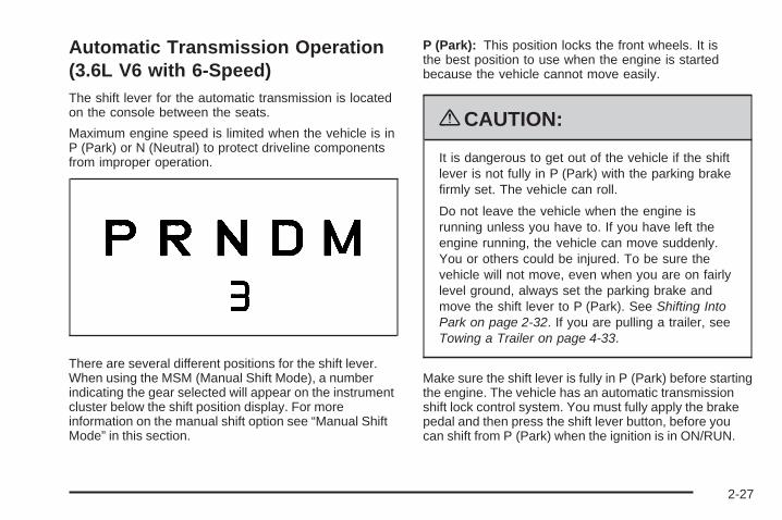
Automatic Transmission Operation(3.6L V6 with 6-Speed)The shift lever for the automatic transmission is locatedon the console between the seats.
Maximum engine speed is limited when the vehicle is inP (Park) or N (Neutral) to protect driveline componentsfrom improper operation.
There are several different positions for the shift lever.When using the MSM (Manual Shift Mode), a numberindicating the gear selected will appear on the instrumentcluster below the shift position display. For moreinformation on the manual shift option see “Manual ShiftMode” in this section.
P (Park): This position locks the front wheels. It isthe best position to use when the engine is startedbecause the vehicle cannot move easily.
{CAUTION:
It is dangerous to get out of the vehicle if the shiftlever is not fully in P (Park) with the parking brakefirmly set. The vehicle can roll.
Do not leave the vehicle when the engine isrunning unless you have to. If you have left theengine running, the vehicle can move suddenly.You or others could be injured. To be sure thevehicle will not move, even when you are on fairlylevel ground, always set the parking brake andmove the shift lever to P (Park). See Shifting IntoPark on page 2-32. If you are pulling a trailer, seeTowing a Trailer on page 4-33.
Make sure the shift lever is fully in P (Park) before startingthe engine. The vehicle has an automatic transmissionshift lock control system. You must fully apply the brakepedal and then press the shift lever button, before youcan shift from P (Park) when the ignition is in ON/RUN.
2-27

If you cannot shift out of P (Park), ease pressure on theshift lever and push the shift lever all way into P (Park)as you maintain brake application. Then press the shiftlever button and move the shift lever into another gear.See Shifting Out of Park on page 2-33.
R (Reverse): Use this gear to back up.
Notice: Shifting to R (Reverse) while the vehicle ismoving forward could damage the transmission.The repairs would not be covered by the vehiclewarranty. Shift to R (Reverse) only after the vehicleis stopped.
To rock the vehicle back and forth to get out of snow,ice, or sand without damaging the transmission, see IfYour Vehicle is Stuck in Sand, Mud, Ice, or Snow onpage 4-19.
N (Neutral): In this position, the engine does notconnect with the wheels. To restart the engine whenthe vehicle is already moving, use N (Neutral) only.
{CAUTION:
Shifting into a drive gear while the engine isrunning at high speed is dangerous. Unless yourfoot is firmly on the brake pedal, the vehicle couldmove very rapidly. You could lose control and hitpeople or objects. Do not shift into a drive gearwhile the engine is running at high speed.
Notice: Shifting out of P (Park) or N (Neutral) withthe engine running at high speed may damage thetransmission. The repairs would not be coveredby the vehicle warranty. Be sure the engine is notrunning at high speed when shifting the vehicle.
2-28

D (Drive): This position is for normal driving. It providesthe best fuel economy. If the vehicle needs more powerfor passing, and it is:
• Going less than 35 mph (55 km/h), push theaccelerator pedal about halfway down.
• Going about 35 mph (55 km/h) or more, push theaccelerator pedal all the way down.
The vehicle will shift down to the next gear and havemore power.
Downshifting the transmission in slippery road conditionscould result in skidding, see Skidding under Loss ofControl on page 4-12.
Notice: Spinning the tires or holding the vehicle inone place on a hill using only the accelerator pedalmay damage the transmission. The repair will not becovered by the vehicle warranty. If you are stuck, donot spin the tires. When stopping on a hill, use thebrakes to hold the vehicle in place.
MSM (Manual Shift Mode): This position, available onthe models with the MSM (Manual Shift Mode), allowsyou to change gears similar to a manual transmission.If the vehicle has this feature, see “MSM (ManualShift Mode)”.
MSM (Manual Shift Mode)
To use this feature, do the following:
1. Move the shift lever from D (Drive) to the left intothe manual gate.While driving in manual shift mode, the transmissionwill remain in the driver gear selected. When comingto a stop in the manual position, the vehicle willautomatically shift to 1 (First) gear.
2. Push the shift lever forward toward the plus (+) toupshift or rearward toward the minus (−) todownshift.When using the MSM (Manual Shift Mode) thenumber of the gear selected will appear on theinstrument cluster below the shift position display.
2-29

In manual shift mode all six forward gears can beselected.
While using the MSM (Manual Shift Mode) featurethe vehicle will have operation similar to a manualtransmission. You can use this for sport driving or whendriving hilly roads to stay in gear longer or to downshiftfor more power or engine braking.
The transmission will only allow you to shift into gearsappropriate for the vehicle speed:
• The transmission will not automatically shift to thenext higher gear without moving the shift lever.
• The transmission will not allow shifting to the nextlower gear if the vehicle speed is too high.
If the vehicle does not respond to a gear change, ordetects a problem with the transmission, the rangeof gears may be reduced and the Malfunction IndicatorLamp will come on. See Malfunction Indicator Lampon page 3-34.
Transmission OverheatingIf the transmission fluid temperature rises above270°F (132°C) or rises rapidly, the Engine CoolantTemperature Warning Light will flash. See EngineCoolant Temperature Warning Light on page 3-32 formore information. When the transmission overheats itwill go into a protection mode and will default into adifferent shift sequence to help cool the transmissionfluid. This shift sequence is the same for both D (Drive)position and manual mode. Continue driving the vehiclein either position depending on the required vehiclespeed and load. Once the fluid temperature lowers to thenormal temperature range, the transmission will return tothe normal shift patterns. Towing or driving on long hillscan cause the transmission fluid temperature to be higherthan normal. If the transmission fluid temperature willnot cool, you may need to pull over and check thetransmission fluid level. You should also check theengine coolant temperature. If it is hot, see EngineOverheating on page 5-28.
2-30

2 (Second) and 3 (Third) Gear StartFeatureWhen accelerating the vehicle from a stop in snowyand icy conditions, you may want to select 2 (Second)and 3 (Third) gear. A higher gear, and light application ofthe gas pedal, may allow you to gain more traction onslippery surfaces.
With the MSM (Manual Shift Mode), the vehicle canaccelerate from a stop in 2 (Second) or 3 (Third).
1. Move the shift lever from D (Drive) into themanual gate.
2. With the vehicle stopped, move the shift leverforward to select 2 (Second) or 3 (Third). Thevehicle will start from a stop position in 2 (Second)or 3 (Third).
3. Once the vehicle is moving select the desired drivegear or move the shift lever to the D (Drive)position.
Parking Brake
The parking brake lever is located to the right of thedriver seat.
To set the parking brake, hold the brake pedal downand pull up on the parking brake lever. If the ignition ison, the brake system warning light will come on.
To release the parking brake, hold the brake pedal down.Pull the parking brake lever up until you can press therelease button. Hold the release button in as you movethe brake lever all the way down.
2-31

Make sure to release the parking brake before drivingthe vehicle.
If the parking brake is applied and the vehicle is movingat least 4 mph (6 km/h), a chime will activate toremind you to release the parking brake.
Notice: Driving with the parking brake on canoverheat the brake system and cause prematurewear or damage to brake system parts. Make surethat the parking brake is fully released and the brakewarning light is off before driving.
Shifting Into Park
{CAUTION:
It can be dangerous to get out of the vehicle ifthe shift lever is not fully in P (Park) with theparking brake firmly set. The vehicle can roll.
CAUTION: (Continued)
CAUTION: (Continued)
If you have left the engine running, the vehicle canmove suddenly. You or others could be injured.To be sure the vehicle will not move, even whenyou are on fairly level ground, use the steps thatfollow. If you are pulling a trailer, see Towing aTrailer on page 4-33.
1. Hold the brake pedal down and set the parkingbrake. See Parking Brake on page 2-31 for moreinformation.
2. Move the shift lever into P (Park) by pressing thebutton on the shift lever and pushing the lever allthe way toward the front of the vehicle.
3. Turn the ignition key to LOCK/OFF.
4. Remove the key and take it with you. If you canleave the vehicle with the key, the vehicle is inP (Park).
2-32

Leaving the Vehicle With the EngineRunning
{CAUTION:
It can be dangerous to leave the vehicle with theengine running. The vehicle could move suddenly ifthe shift lever is not fully in P (Park) with the parkingbrake firmly set. And, if you leave the vehicle withthe engine running, it could overheat and evencatch fire. You or others could be injured. Do notleave the vehicle with the engine running.
If you have to leave the vehicle with the engine running,be sure the vehicle is in P (Park) and the parking brake isfirmly set before you leave it. After you have moved theshift lever into P (Park), hold the regular brake pedaldown. Then, see if you can move the shift lever awayfrom P (Park) without first pressing the button on theconsole shift lever. If you can, it means that the shiftlever was not fully locked into P (Park).
Torque LockTorque lock is when the weight of the vehicle puts toomuch force on the parking pawl in the transmission.This happens when parking on a hill and shifting thetransmission into P (Park) is not done properly and then itis difficult to shift out of P (Park). To prevent torque lock,set the parking brake and then shift into P (Park). To findout how, see ‘‘Shifting Into P (Park)’’ listed previously.If torque lock does occur, your vehicle may need to bepushed uphill by another vehicle to relieve the parkingpawl pressure, so you can shift out of P (Park).
Shifting Out of ParkThe vehicle is equipped with an electronic shift lockrelease system. The shift lock release is designed to:
• Prevent ignition key removal unless the shiftlever is in P (Park) with the shift lever button fullyreleased, and
• Prevent movement of the shift lever out ofP (Park), unless the ignition is in ON/RUN orACC/ACCESSORY and the regular brake pedalis applied.
The shift lock release is always functional except in thecase of an uncharged or low voltage (less than 9 volt)battery.
2-33

If the vehicle has an uncharged battery or a battery withlow voltage, try charging or jump starting the battery.See Jump Starting on page 5-36 for more information.
To shift out of P (Park):
1. Apply the brake pedal.
2. Press the shift lever button.
3. Move the shift lever to the desired position.
If you still are unable to shift out of P (Park):
1. Fully release the shift lever button.
2. While holding down the brake pedal, press the shiftlever button again.
3. Move the shift lever to the desired position.
If you still cannot move the shift lever from P (Park), seeyour dealer/retailer.
Parking Over Things That Burn
{CAUTION:
Things that can burn could touch hot exhaustparts under the vehicle and ignite. Do not parkover papers, leaves, dry grass, or other things thatcan burn.
2-34

Engine Exhaust
{CAUTION:
Engine exhaust contains Carbon Monoxide (CO)which cannot be seen or smelled. Exposure to COcan cause unconsciousness and even death.
Exhaust may enter the vehicle if:• The vehicle idles in areas with poor ventilation
(parking garages, tunnels, deep snow thatmay block underbody airflow or tail pipes).
• The exhaust smells or sounds strange ordifferent.
• The exhaust system leaks due to corrosion ordamage.
CAUTION: (Continued)
CAUTION: (Continued)
• The vehicle’s exhaust system has beenmodified, damaged or improperly repaired.
• There are holes or openings in thevehicle body from damage or after-marketmodifications that are not completely sealed.
If unusual fumes are detected or if it is suspectedthat exhaust is coming into the vehicle:
• Drive it only with the windowscompletely down.
• Have the vehicle repaired immediately.
Never park the vehicle with the engine running inan enclosed area such as a garage or a buildingthat has no fresh air ventilation.
2-35
Running the Vehicle While ParkedIt is better not to park with the engine running. But if youever have to, here are some things to know.
{CAUTION:
Idling a vehicle in an enclosed area with poorventilation is dangerous. Engine exhaust mayenter the vehicle. Engine exhaust contains CarbonMonoxide (CO) which cannot be seen or smelled.It can cause unconsciousness and even death.Never run the engine in an enclosed area thathas no fresh air ventilation. For more information,see Engine Exhaust on page 2-35.
{CAUTION:
It can be dangerous to get out of the vehicle ifthe automatic transmission shift lever is not fullyin P (Park) with the parking brake firmly set.
CAUTION: (Continued)
CAUTION: (Continued)
The vehicle can roll. Do not leave the vehiclewhen the engine is running unless you have to.If you have left the engine running, the vehicle canmove suddenly. You or others could be injured.To be sure the vehicle will not move, even whenyou are on fairly level ground, always set theparking brake and move the shift lever to P (Park).
Follow the proper steps to be sure the vehicle will notmove. See Shifting Into Park on page 2-32.
If parking on a hill and pulling a trailer, see Towing aTrailer on page 4-33.
Mirrors
Manual Rearview MirrorHold the inside rearview mirror in the center to move it fora clearer view of behind your vehicle. Adjust the mirror toreduce the glare of headlamps from behind you. Push thetab forward for daytime use and pull it for nighttime use.
2-36

Vehicles with OnStar® have three additional controlbuttons located at the bottom of the mirror. See yourdealer/retailer for more information on the system andhow to subscribe to OnStar. See OnStar® System onpage 2-38 for more information about the servicesOnStar provides.
Automatic Dimming Rearview MirrorHold the inside rearview mirror in the center to moveit for a clearer view of behind your vehicle.
Adjust the mirror to reduce the glare of headlamps frombehind you. Press AUTO or ( located in the lowercenter of the mirror to turn automatic dimming on or off.The indicator light comes on when this feature is on.
For vehicles with OnStar®, press the O located on thelower part of the mirror, for up to six seconds to turnautomatic dimming on or off.
Vehicles with OnStar have three additional controlbuttons located at the bottom of the mirror. See yourdealer/retailer for more information on the systemand how to subscribe to OnStar. See OnStar® Systemon page 2-38 for more information about the servicesOnStar provides.
Outside Power Mirrors
Controls for the outsidepower mirrors are locatedon the instrument panel.
To adjust the mirrors:
1. Move the selector switch to the left or right tochoose the driver or passenger mirror.
2. Press the corresponding edges of the round controlpad to move each mirror to the desired direction.
3. Adjust each outside mirror so that a little of thevehicle and the area behind it can be seen.
2-37

Outside Convex Mirrors
{CAUTION:
A convex mirror can make things, like othervehicles, look farther away than they really are.If you cut too sharply into the right lane, you couldhit a vehicle on the right. Check the inside mirroror glance over your shoulder before changinglanes.
The passenger side mirror is convex shaped. A convexmirror’s surface is curved so more can be seen fromthe driver’s seat.
OnStar® System
OnStar uses several innovative technologies and liveadvisors to provide a wide range of safety, security,information, and convenience services. If the airbagsdeploy, the system is designed to make an automaticcall to OnStar Emergency advisors who can requestemergency services be sent to your location. If the keysare locked in the vehicle, call OnStar at 1-888-4-ONSTARto have a signal sent to unlock the doors. OnStarHands-Free Calling, including 30 trial minutes goodfor 60 days, is available on most vehicles. OnStarTurn-by-Turn Navigation service, with one trial route, isavailable on most vehicles. Press the OnStar button tohave an OnStar advisor contact Roadside Service.
2-38

OnStar service is provided subject to the OnStar Termsand Conditions included in the OnStar Subscriber glovebox literature.
Some services such as Remote Door Unlock or StolenVehicle Location Assistance may not be available untilthe owner of the vehicle registers with OnStar. After thefirst prepaid year, contact OnStar to select a monthlyor annual subscription payment plan. If a payment planis not selected, the OnStar system and all services,including airbag notification and emergency services,may be deactivated and no longer available. For moreinformation visit onstar.com (U.S.) or onstar.ca (Canada),or press the OnStar button to speak with an advisor.
Not all OnStar services are available on all vehicles.To check if this vehicle is able to provide the servicesdescribed below, or for a full description of OnStarservices and system limitations, see the OnStar Owner’sGuide in the glove box or visit onstar.com (U.S.) oronstar.ca (Canada), contact OnStar at 1-888-4-ONSTAR(1-888-466-7827) or TTY 1-877-248-2080, or press theOnStar button to speak with an OnStar advisor 24 hoursa day, 7 days a week.
OnStar Services Available with theSafe & Sound Plan• Automatic Notification of Airbag Deployment
• Advanced Automatic Crash Notification (AACN)(If equipped)
• Link to Emergency Services
• Roadside Assistance
• Stolen Vehicle Location Assistance
• Remote Door Unlock/Vehicle Alert
• OnStar Vehicle Diagnostic Email
• GM Goodwrench On Demand Diagnostics
• OnStar Hands-Free Calling with 30 trial minutes
• OnStar Virtual Advisor (U.S. Only)
OnStar Services Included withDirections & Connections Plan• All Safe and Sound Plan Services
• OnStar Turn-by-Turn Navigation (If equipped) orDriving Directions - Advisor delivered
• RideAssist
• Information and Convenience Services
2-39

OnStar Hands-Free CallingOnStar Hands-Free Calling allows eligible OnStarsubscribers to make and receive calls using voicecommands. Hands-Free Calling is fully integrated into thevehicle, and can be used with OnStar Pre-Paid MinutePackages. Most vehicles include 30 trial minutes goodfor 60 days. Hands-Free Calling can also be linked toa Verizon Wireless service plan in the U.S. or a BellMobility service plan in Canada, depending on eligibility.To find out more, refer to the OnStar Owner’s Guide inthe vehicle’s glove box, visit onstar.com or onstar.ca, orspeak with an OnStar advisor by pressing the OnStarbutton or calling 1-888-4-ONSTAR (1-888-466-7827).
OnStar Turn-by-Turn NavigationVehicles with the OnStar Turn-by-Turn Navigationsystem can provide voice-guided driving directions.Press the OnStar button to have an OnStar advisorlocate a business or address and download drivingdirections to the vehicle. Voice-guided directions to thedesired destination will play through the audio systemspeakers. See the OnStar Owner’s Guide for moreinformation.
OnStar Virtual AdvisorOnStar Virtual Advisor is a feature of OnStar Hands-FreeCalling that uses minutes to access location-basedweather, local traffic reports, and stock quotes. Press thephone button and give a few simple voice commandsto browse through the various topics. See the OnStarOwner’s Guide for more information. This feature isonly available in the continental U.S.
OnStar Steering Wheel ControlsThis vehicle may have a Talk/Mute button that canbe used to interact with OnStar Hands-Free Calling.See Audio Steering Wheel Controls on page 3-118 formore information.
On some vehicles, the mute button can be used todial numbers into voice mail systems, or to dial phoneextensions. See the OnStar Owner’s Guide for moreinformation.
2-40

How OnStar Service WorksThe OnStar system can record and transmit vehicleinformation. This information is automatically sent to anOnStar Call Center when the OnStar button is pressed,the emergency button is pressed, or if the airbags orAACN system deploy. This information usually includesthe vehicle’s GPS location and, in the event of a crash,additional information regarding the crash that the vehiclewas involved in (e.g. the direction from which the vehiclewas hit). When the Virtual Advisor feature of OnStarHands-Free Calling is used, the vehicle also sendsOnStar the vehicle’s GPS location so they can provideservices where it is located.
OnStar service cannot work unless the vehicle is in aplace where OnStar has an agreement with a wirelessservice provider for service in that area. OnStar servicealso cannot work unless the vehicle is in a place wherethe wireless service provider OnStar has hired for thatarea has coverage, network capacity and reception whenthe service is needed, and technology that is compatiblewith the OnStar service. Not all services are availableeverywhere, particularly in remote or enclosed areas, orat all times.
Location information about the vehicle is only availableif the GPS satellite signals are unobstructed andavailable.
The vehicle must have a working electrical system,including adequate battery power, for the OnStarequipment to operate. There are other problems OnStarcannot control that may prevent OnStar from providingOnStar service at any particular time or place. Someexamples are damage to important parts of the vehicle ina crash, hills, tall buildings, tunnels, weather or wirelessphone network congestion.
Your ResponsibilityIncrease the volume of the radio if the OnStar advisorcannot be heard. If the light next to the OnStar buttonsis red, the system may not be functioning properly.Press the OnStar button and request a vehiclediagnostic. If the light appears clear (no light isappearing), your OnStar subscription has expired andall services have been deactivated. Press the OnStarbutton to confirm that the OnStar equipment is active.
2-41

Storage Areas
Glove BoxTo open the glove box, pull the handle to the left andpull the glove box door down until it stops and isfully open.
CupholdersCupholders are located on the lower front of the centerconsole. Pull-out cupholders are located at the bottomof the armrest and on the back of the rear seat centerconsole. Cupholders are also located on the rear seatarmrest.
Center Console StorageYour vehicle has a center console armrest with storagearea. Use the lever on the front of the console toopen it.
Luggage Carrier
{CAUTION:
If something is carried on top of the vehicle that islonger or wider than the luggage carrier — likepaneling, plywood, or a mattress — the wind cancatch it while the vehicle is being driven. This cancause a driver to lose control. The item beingcarried could be violently torn off, and this couldcause a collision, and damage the vehicle. Itemsmay be carried inside. Never carry somethinglonger or wider than the luggage carrier on top ofthe vehicle.
If equipped, a luggage carrier allows you to load thingson top of your vehicle. The luggage carrier has side railsattached to the roof, sliding crossrails, if the vehicle hasthem, and places to use for tying things down. These letyou load some things on top of your vehicle, as long asthey are not wider or longer than the luggage carrier.
The roof rack crossrails lock along the straight sectionof the side rail.
2-42

Press the levers down until the locking mechanismsfully engage to the side rail. Make sure each lever is inthe down position. The crossrail will not slide whenproperly engaged.
To move the crossrail, pull up on the end levers on eachside of the crossrail to the upright position. This willrelease the locking mechanism from the siderail. Lift andplace the crossrail into the new position. Press the leversdown until the locking mechanisms fully engage to theside rail. Make sure each lever is in the down position.The crossrail will not slide when properly engaged.
Notice: Loading cargo on the luggage carrier thatweighs more than 150 lbs (68 kg) or hangs over therear or sides of the vehicle may damage your vehicle.When loading cargo, tie it to the crossrail and againstthe siderail. Lock the crossrails to the far forward andbackward location to make sure the load is evenlydistributed on the luggage carrier.
Do not stand on the plastic lower body panels whenloading cargo on the luggage carrier.
Loading cargo on the luggage carrier will make thecenter of vehicle gravity higher. Avoid high speeds,sudden starts, sharp turns, sudden braking or abruptmaneuvers. This could result in loss of control ofthe vehicle.
Do not exceed the maximum vehicle capacity whenloading your vehicle. For more information on vehiclecapacity and loading, see Loading the Vehicle onpage 4-20.
To prevent damage or loss of cargo as you are driving,check now and then to make sure the luggage carriercrossrails are locked and cargo is still securely fastened.
When the luggage carrier is not in use, store thecrossrail inside the vehicle. If not possible, lock onecrossrail at the rear most position on the siderails andlock the other crossrail above the opening of therear door to reduce wind noise.
2-43

Rear Compartment StoragePanel/CoverYour vehicle may have an adjustable panel/cargo coverfeature. The panel/cargo cover can be adjusted intothree positions.
There is a flip panel towards the front of the cargocover. You may have to flip this panel upward in orderto gain access to the cargo cover.
To use the panel in the lower position, do the following:
1. Insert the front corners of the panel into thelower guides.
2. Slide the panel forward.
3. Press down on the back of the panel to lock it inplace.
The panel can be used in this position if you needadditional space above the panel. Place the cargo ontop of the panel in this position.
2-44

{CAUTION:
If you were to carry things on the adjustable panelwhen it is in the upper (cargo cover) or centerpositions, during a sudden vehicle movement or acrash, those things could be thrown around in thevehicle. You or others could be injured. When it isin the upper or center position, always secure anycargo on the floor beneath the panel/cover.
To use the panel in the center position, do the following:
1. Insert the front corners of the panel into themiddle guides.
2. Slide the panel forward.
3. Press down and pull rearward on the back of thepanel to lock it in place.
The panel can be used in this position when you haveto place a flat or spare tire in the rear cargo area.
To use the panel in the upper position, do the following:
1. Insert the front corners of the panel into the topguides.
2. Slide the panel forward.
3. Press down and pull rearward on the back of thepanel to lock it in place.
This can be used as a cargo cover for the rear area.The panel may be installed either carpet or plastic sideup. The panel may also be used as a table in thisposition. See Table on page 2-46 for more information.
Rear Seat ArmrestVehicles with a rear seat armrest, have two cupholders.Pull the armrest down from the rear seatback toaccess the cupholders.
2-45

Table
Your vehicle may have an adjustable panel that alsofunctions as a table. The maximum load for the table is100 lbs. distributed (45 kg).
To set up the table, do the following:
1. With the adjustable panel in the upper position,pull it rearward to position it for use as a table.The plastic side should be up.
2. Turn the knob to release the leg from the plasticside of the table and turn the leg outward.
3. Set the table leg onto the liftgate lock striker at therear edge of the vehicle.
Make sure to place the table leg securely onto theliftgate lock striker.
Notice: Driving with the panel extended into thetable position could damage your vehicle. Alwayshave the panel in the stored position while youare driving.
Notice: Placing hot items on the surface of thetable could damage it. Always be sure that the itemsthat are placed on the surface of the table are ofmoderate temperature.
There are four hooks located on the table that can beused for grocery bags.
2-46

Convenience NetUse the convenience net, located in the rear, to storesmall loads as far forward as possible. The netshould not be used to store heavy loads.
SunroofIf the vehicle is equipped with a sunroof, the controlsto operate it are located on the headliner above therearview mirror. The ignition must be in RUN/ON orACC/ACCESSORY, or Retained Accessory Power (RAP)must be active, to operate the sunroof. See RetainedAccessory Power (RAP) on page 2-21 for moreinformation.
To express-open thesunroof glass panel andsunshade, press the switchrearward and release it.
To stop the sunroof before it is completely open, pressthe switch rearward again. The sunshade cannot beclosed with the sunroof open.
To close the sunroof, press forward and hold the switchuntil the sunroof stops, lifts and seals at the back ofthe sunroof glass. Press forward on the switch again,to make sure the sunroof is fully closed.
To put the sunroof in the vent position, pull down on thefront of the switch. Push up on the front of the switchto close it.
2-47

✍ NOTES
2-48

Instrument Panel Overview ...............................3-4Hazard Warning Flashers ................................3-6Horn .............................................................3-6Tilt Wheel .....................................................3-6Turn Signal/Multifunction Lever .........................3-7Turn and Lane-Change Signals ........................3-7Headlamp High/Low-Beam Changer ..................3-8Flash-to-Pass .................................................3-8Windshield Wipers ..........................................3-8Windshield Washer .........................................3-9Rear Window Wiper/Washer ...........................3-10Cruise Control ..............................................3-10Headlamps ..................................................3-13Headlamps on Reminder ................................3-13Daytime Running Lamps (DRL) .......................3-13Automatic Headlamp System ..........................3-14Fog Lamps ..................................................3-14Instrument Panel Brightness ...........................3-15Dome Lamp .................................................3-15Entry Lighting ...............................................3-15Map Lamps .................................................3-16Cargo Lamp .................................................3-16Electric Power Management ...........................3-16Battery Run-Down Protection ..........................3-17Accessory Power Outlet(s) .............................3-18Ashtray(s) and Cigarette Lighter ......................3-18
Climate Controls ............................................3-19Climate Control System .................................3-19Outlet Adjustment .........................................3-23Passenger Compartment Air Filter ...................3-23
Warning Lights, Gages, and Indicators ............3-24Instrument Panel Cluster ................................3-25Speedometer and Odometer ...........................3-26Trip Odometer ..............................................3-26Tachometer .................................................3-26Safety Belt Reminders ...................................3-27Airbag Readiness Light ..................................3-28Passenger Airbag Status Indicator ...................3-29Charging System Light ..................................3-30Brake System Warning Light ..........................3-30Antilock Brake System (ABS) Warning Light .....3-31Traction Control System (TCS) Warning Light ......3-32Engine Coolant Temperature Warning Light ......3-32Engine Coolant Temperature Gage ..................3-33Tire Pressure Light .......................................3-33Malfunction Indicator Lamp .............................3-34Oil Pressure Light (US-Canada) ......................3-36Change Engine Oil Light ................................3-37Security Light ...............................................3-37Fog Lamp Light ............................................3-37Cruise Control Light ......................................3-38Reduced Engine Power Light .........................3-38
Section 3 Instrument Panel
3-1

Highbeam On Light .......................................3-38Service All-Wheel Drive Light .........................3-39All-Wheel Drive Disabled Light ........................3-39Gate Ajar Light .............................................3-40Door Ajar Light .............................................3-40Service Vehicle Soon Light ............................3-40Fuel Gage ...................................................3-41Low Fuel Warning Light .................................3-41
Driver Information Center (DIC) .......................3-42DIC Operation and Displays ...........................3-42DIC Compass ..............................................3-47DIC Warnings and Messages .........................3-49DIC Vehicle Personalization ............................3-57
Audio System(s) .............................................3-64Setting the Clock ..........................................3-65Radio(s) ......................................................3-67Using an MP3 (Radio with CD or
Six-Disc CD Player) ...................................3-87Using an MP3 (Radio with CD and
DVD Player) .............................................3-92XM Radio Messages .....................................3-97Navigation/Radio System ...............................3-98Bluetooth® ...................................................3-98Rear Seat Entertainment (RSE) System .........3-109Theft-Deterrent Feature ................................3-118Audio Steering Wheel Controls ......................3-118Radio Reception .........................................3-119Multi-Band Antenna .....................................3-120
Section 3 Instrument Panel
3-2

✍ NOTES
3-3

Instrument Panel Overview
3-4

The main components of the instrument panel are the following:
A. Outlet Adjustment on page 3-23.B. Turn Signal/Multifunction Lever on page 3-7.C. Instrument Panel Cluster on page 3-25.D. Windshield Wipers on page 3-8.E. DIC Operation and Displays on page 3-42.F. Hazard Warning Flashers on page 3-6.G. Passenger Airbag Status Indicator on page 3-29.H. Rear Window Wiper/Washer on page 3-10.
Fog Lamps on page 3-14.I. Outside Power Mirrors on page 2-37.J. Instrument Panel Brightness on page 3-15.
K. Cruise Control on page 3-10.L. Tilt Wheel on page 3-6.M. Horn on page 3-6.N. Audio Steering Wheel Controls on page 3-118.O. Audio System(s) on page 3-64.P. Shift Lever. See Shifting Into Park on page 2-32.Q. Traction Control System (TCS) on page 4-7.R. Power Windows on page 2-15.S. Climate Control System on page 3-19. Heated Seats
on page 1-4 (If Equipped).T. Glove Box on page 2-42.
3-5

Hazard Warning Flashers
| (Hazard Warning Flasher): Press this buttonlocated on the instrument panel, to make the front andrear turn signal lamps flash on and off. This warnsothers that you are having trouble.
Press | again to turn the flashers off.
HornPress near or on the horn symbols on the steeringwheel pad to sound the horn.
Tilt WheelThe vehicle has a tilt wheel that lets the steering wheelbe adjusted.
The tilt lever is located on the left side of the steeringcolumn.
To tilt the wheel, hold the steering wheel and pushthe lever down. Then, move the steering wheel to acomfortable position and pull the lever up firmly tolock the column in place.
Do not adjust the steering wheel while driving.
3-6
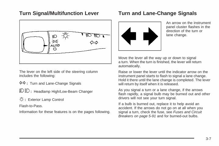
Turn Signal/Multifunction Lever
The lever on the left side of the steering columnincludes the following:
G : Turn and Lane-Change Signals
53 : Headlamp High/Low-Beam Changer
O : Exterior Lamp Control
Flash-to-Pass.
Information for these features is on the pages following.
Turn and Lane-Change Signals
An arrow on the instrumentpanel cluster flashes in thedirection of the turn orlane change.
Move the lever all the way up or down to signala turn. When the turn is finished, the lever will returnautomatically.
Raise or lower the lever until the indicator arrow on theinstrument panel starts to flash to signal a lane change.Hold it there until the lane change is completed. The leverwill return by itself when it is released.
As you signal a turn or a lane change, if the arrowsflash rapidly, a signal bulb may be burned out and otherdrivers will not see your turn signal.
If a bulb is burned out, replace it to help avoid anaccident. If the arrows do not go on at all when yousignal a turn, check the fuse, see Fuses and CircuitBreakers on page 5-91 and for burned-out bulbs.
3-7

Headlamp High/Low-Beam ChangerTo change the headlamps from low beam to high,push the turn signal lever away from you. To changefrom high beam to low beam, pull the turn signallever towards you. To flash the high beams from lowbeam, pull the turn signal lever all the way towards you.Then release it.
When the high beamsare on, this light on theinstrument panel clusterwill also be on.
Flash-to-PassThis feature lets you use your high-beam headlamps tosignal a driver in front of you that you want to pass.
To flash the high beams from low beam, pull the turnsignal/multifunction lever all the way towards you.Then release it.
Windshield Wipers
The windshield wiper lever is located on the right side ofthe steering column.
Move the lever to the following positions:
1 (High Speed): For steady wiping at high speed.
6 (Low Speed): For steady wiping at low speed.
& (Delay): Sets a delay between wipes.
3-8

6 (Delay Adjustment): Move the lever to the delayposition to choose a delayed wiping cycle. Turn theintermittent adjust band down for a longer delay orup for a shorter delay.
9 (Off): Turns off the windshield wipers.
8 (Mist): Move the lever all the way down to mist andrelease for a single wiping cycle. The windshield wipersstop after one wipe and the lever returns to its startingposition. Hold the lever on mist longer for more wipes.
Clear ice and snow from the wiper blades beforeusing them. If they are frozen to the windshield,gently loosen or thaw them. If the blades do becomedamaged, install new blades or blade inserts.See Windshield Wiper Blade Replacement onpage 5-47.
Heavy snow or ice can overload the wiper motor.A circuit breaker will stop the motor until it coolsdown. Clear away snow or ice to prevent anoverload.
Windshield Washer
{CAUTION:
In freezing weather, do not use your washer untilthe windshield is warmed. Otherwise the washerfluid can form ice on the windshield, blocking yourvision.
There is a button marked with the windshield washersymbol at the end of the windshield wiper lever. Pressthis button to spray washer fluid on the windshield.The wipers will run for a few cycles to clear the windowand then either stop or return to your preset speed.For more wash cycles, press and hold the button longer.
3-9

Rear Window Wiper/WasherThe rear wiper and rear wash buttons are located onthe instrument panel above the audio system.
Z (Rear Wiper): Press to turn the rear wiper on andoff. When the wiper is on it runs intermittently at apreset speed.
Y (Wash): Press to spray washer fluid on the rearwindow. The window wiper will also come on. Releasethe button when enough fluid has been sprayed onthe window. The rear wiper will run a few more cyclesafter it is released. If the rear wiper function was alreadyon, prior to pressing the wash button, it stays on untilthe wiper button is pressed again.
The rear window washer uses the same fluid that isin the windshield washer reservoir. See WindshieldWasher Fluid on page 5-31.
Cruise ControlCruise control lets a speed of about 25 mph (40 km/h)or more be maintained without keeping your foot onthe accelerator. Cruise control does not work at speedsbelow 25 mph (40 km/h).
When the brakes are applied, the cruise controlshuts off.
If the vehicle is in cruise control and the Traction ControlSystem (TCS) begins to limit wheel spin, the cruisecontrol automatically disengages. See Traction ControlSystem (TCS) on page 4-7. When road conditions allow,the cruise control can be used again.
{CAUTION:
Cruise control can be dangerous where you cannotdrive safely at a steady speed. So, do not use thecruise control on winding roads or in heavy traffic.
Cruise control can be dangerous on slippery roads.On such roads, fast changes in tire traction cancause excessive wheel slip, and you could losecontrol. Do not use cruise control on slippery roads.
3-10

Setting Cruise Control
{CAUTION:
If you leave your cruise control on when you arenot using cruise, you might hit a button and go intocruise when you do not want to. You could bestartled and even lose control. Keep the cruisecontrol switch off until you want to use cruisecontrol.
The cruise control buttonsare located on the steeringwheel.
I (On/Off): Press I to turn the cruise controlsystem on and off.
RES+ (Resume): Press to resume a set speed and toaccelerate the speed.
SET− (Set): Press to set a speed and to decreasethe speed.
[ CANCEL: Press to cancel cruise control.
To set a speed do the following:
1. Press I to turn cruise control on. The indicatorlight on the button comes on.
2. Get up to the desired speed.
3. Press the SET− and release it. This instrumentpanel cluster light J comes on after the systemis engaged.
4. Take your foot off the accelerator pedal.
Resuming a Set SpeedIf the cruise control is at a set speed and thebrakes are applied, this disengages the cruise control.The instrument panel cluster light J also goes out,indicating cruise is no longer engaged. To return tothe previously set speed, it does not need to be reset.
Once the vehicle is at a speed of about 25 mph(40 km/h) or more, briefly press RES+. The vehiclegoes back to the previous set speed and stays there.
3-11

Increasing Speed While Using CruiseControlThere are two ways to go to a higher speed.
• If the cruise control system is already engaged,press and hold the RES+ button until the desiredspeed is reached, then release it.
• To increase the vehicle speed in small amounts,briefly press the RES+ and then release it.Each time this is done, the vehicle goes about1 mph (1.6 km/h) faster.
Reducing Speed While Using CruiseControlIf the cruise control system is already engaged:
• Push and hold the SET− until the desired lowerspeed is reached, then release it.
• To slow down in small amounts, briefly press SET−.Each time this is done, the vehicle goes about1 mph (1.6 km/h) slower.
Passing Another Vehicle While UsingCruise ControlUse the accelerator pedal to increase the vehicle’sspeed. When you take your foot off the pedal, thevehicle slows down to the cruise control speed thatwas set earlier.
Using Cruise Control on HillsHow well the cruise control works on hills depends uponthe vehicle’s speed, load, and the steepness of the hills.When going up steep hills, you might have to step on theaccelerator pedal to maintain the vehicle’s speed. Whengoing downhill, you might have to brake or shift to a lowergear to keep the vehicle at a lower speed. However,when the brakes are applied the cruise control turns off.
Ending Cruise ControlThere are three ways to end the cruise control:
• Step lightly on the brake pedal.
• Press the I button, to turn off the cruise controlsystem.
• Press the [ button.
When cruise control disengages, the cruise symbolin the instrument panel cluster goes out.
Erasing Speed MemoryThe cruise control set speed memory is erased whenthe cruise control or the ignition is turned off.
3-12

HeadlampsThe exterior lamp control is located on the turnsignal/multifunction lever.
O (Exterior Lamp Control): Turn the control with thissymbol on it to operate the exterior lamps.
The exterior lamp control has the following positions:
AUTO (Off/Automatic Headlamps): Automaticmode turns the exterior lamps on and off dependingupon how much light is available outside of the vehicle.
; (Parking Lamps): Turns on the parking lampstogether with the following:
• Sidemarker Lamps
• Taillamps
• License Plate Lamps
• Instrument Panel Lights
53 (Headlamps): Turns on the headlamps, togetherwith the previously listed lamps and lights.
Headlamps on ReminderIf you open the driver’s door with the ignition off and thelamps on, you will hear a warning chime.
Daytime Running Lamps (DRL)Daytime Running Lamps (DRL) can make it easier forothers to see the front of your vehicle during the day.Fully functional Daytime Running Lamps (DRL) arerequired on all vehicles first sold in Canada.
The DRL system will make the low-beam headlampscome on at a reduced brightness in daylight whenthe following conditions are met:
• The ignition is on.
• The exterior lamp band is in the automatic position.
• The transmission is not in P (Park).
• The light sensor determines it is daytime.
• The parking brake is released.
When the DRL are on, the low-beam headlamps will beon at a reduced brightness. The taillamps, sidemarker,instrument panel lights and other lamps will not be on.
When the exterior lamp band is turned to theheadlamp position, the low-beam headlamps come on.The other lamps that come on with the headlamps willalso come on.
When the headlamps are turned off, the regular lampswill go off, and the low-beam headlamps come onto the reduced brightness.
3-13

To idle your vehicle with the DRL off, move the shiftlever to P (Park). The DRL will stay off until theshift lever is moved out of the P (Park) position.
The regular headlamp system should be turned onwhen needed.
Automatic Headlamp SystemWhen it is dark enough outside and the exterior lampscontrol is in the automatic position, the headlampscome on automatically. See Headlamps on page 3-13.
The vehicle has a light sensor located on top of theinstrument panel. Make sure it is not covered, orthe headlamps will be on when they are not needed.
The system may also turn on the headlamps whendriving through a parking garage or tunnel.
Fog LampsUse the fog lamps for better visibility in foggy or mistyconditions.
The fog lamps button is located on the instrument panelabove the radio.
The parking lamps or low-beam headlamps must be onto use the fog lamps.
# : Press to turn the fog lamps on or off.
The fog lamp button is lit when the lamps are on.The fog lamps will go off whenever the high-beamheadlamps are turned on. When the high-beamheadlamps are turned off, the fog lamps will comeon again.
Some localities have laws that require the headlamps tobe on along with the fog lamps.
3-14

Instrument Panel BrightnessThis feature controls the brightness of the instrumentpanel lights.
The control for this featureis located on the instrumentpanel to the left of thesteering column.
Turn the control up to brighten the lights or down todim them.
Dome LampFor vehicles with a dome lamp, move the lever tochange the setting.
9 (Off): Turns the lamp off, even when a door is open.
1 (Door): The lamp comes on automatically when adoor is opened.
+ (On): Turns the dome lamp on.
Entry LightingThe dome lamp and the cargo lamp inside the vehiclecomes on when any door is opened, if the dome lamp isin the door position. In addition, these lamps come onwhen the Remote Keyless Entry (RKE) unlock buttonis pressed. It stays on for 20 seconds or until a door isopened. After the door is opened and then closed, thelight remains on for 20 seconds, or until the key is put inthe ignition and turned to the ON/RUN position.
3-15

Map Lamps
The vehicle may have lamps located on the headlinerabove the rearview mirror. Push on the lens in the lampto turn them on and off.
Cargo LampThe cargo lamp is located over the rear compartment,and is controlled by the dome lamp. See Dome Lampon page 3-15.
Electric Power ManagementThe vehicle has Electric Power Management (EPM) thatestimates the battery’s temperature and state of charge.It then adjusts the voltage for best performance andextended life of the battery.
When the battery’s state of charge is low, the voltageis raised slightly to quickly bring the charge back up.When the state of charge is high, the voltage is loweredslightly to prevent overcharging. If the vehicle has avoltmeter gage or a voltage display on the DriverInformation Center (DIC), you may see the voltagemove up or down. This is normal. If there is a problem,an alert will be displayed.
3-16

The battery can be discharged at idle if the electricalloads are very high. This is true for all vehicles. This isbecause the generator (alternator) may not be spinningfast enough at idle to produce all the power that isneeded for very high electrical loads.
A high electrical load occurs when several of thefollowing are on, such as: headlamps, high beams,fog lamps, rear window defogger, climate control fanat high speed, heated seats, engine cooling fans,trailer loads, and loads plugged into accessory poweroutlets.
EPM works to prevent excessive discharge of thebattery. It does this by balancing the generator’s outputand the vehicle’s electrical needs. It can increase engineidle speed to generate more power, whenever needed.It can temporarily reduce the power demands of someaccessories.
Normally, these actions occur in steps or levels, withoutbeing noticeable. In rare cases at the highest levels ofcorrective action, this action may be noticeable to the
driver. If so, a Driver Information Center (DIC) messagemight be displayed, such as BATTERY SAVER ACTIVE,BATTERY VOLTAGE LOW, or LOW BATTERY. If thismessage is displayed, it is recommended that the driverreduce the electrical loads as much as possible. See DICWarnings and Messages on page 3-49.
Battery Run-Down ProtectionThe vehicle has a battery saver feature designed toprotect the vehicle’s battery.
When any interior lamp is left on and the ignitionis turned off, the battery rundown protection systemwill automatically turn the lamp off after 20 minutes.This will avoid draining the battery. This vehicle alsohas a retained accessory power feature. If the radiois on, it will turn off after 10 minutes or if any door on thevehicle is opened. See Retained Accessory Power (RAP)on page 2-21.
3-17

Accessory Power Outlet(s)The accessory power outlets can be used to connectelectrical equipment, such as a cellular phone.
The two accessory power outlets are located in the frontand at the rear of the center console storage area.
To use the outlets, remove the cover. When not in use,always cover the outlet with the protective cap.
Notice: If electrical devices are left plugged intoa power outlet, the battery may drain causing thevehicle not to start or damage to the battery. Thiswould not be covered by the warranty. Always unplugall electrical devices when turning off the vehicle.
Certain electrical accessories may not be compatiblewith the accessory power outlets and could result inblown vehicle or adapter fuses. If you experience aproblem, see your dealer/retailer for additionalinformation on the accessory power outlet.
Notice: Adding any electrical equipment to thevehicle can damage it or keep other componentsfrom working as they should. The repairs wouldnot be covered by the vehicle warranty. Do notuse equipment exceeding maximum amperagerating of 20 amperes. Check with your dealer/retailer before adding electrical equipment.
When adding electrical equipment, be sure to follow theinstallation instructions included with the equipment.
Notice: Improper use of the power outlet can causedamage not covered by the warranty. Do not hangany type of accessory or accessory bracket from theplug because the power outlets are designed foraccessory power plugs only.
Ashtray(s) and Cigarette LighterFor vehicles with a removable ashtray and cigarettelighter, the ashtray can be placed into the front consolecupholders.
To use the lighter, push it in all the way and let go.When it is ready, it pops back out by itself.
Notice: Holding a cigarette lighter in while it isheating will not allow the lighter to back away fromthe heating element when it is hot. Damage fromoverheating may occur to the lighter or heatingelement, or a fuse could be blown. Do not hold acigarette lighter in while it is heating. Do not useequipment exceeding maximum amperage ratingof 15 amperes.
Notice: If papers, pins, or other flammable itemsare put in the ashtray, hot cigarettes or othersmoking materials could ignite them and possiblydamage the vehicle. Never put flammable items inthe ashtray.
3-18

Climate Controls
Climate Control SystemThe heating, cooling, and ventilation for the vehiclecan be controlled with this system. For vehicles with theremote start feature, the climate control system functionsas part of the remote start feature. See Remote KeylessEntry (RKE) System Operation on page 2-5.
A. Fan ControlB. Outside AirC. Temperature ControlD. RecirculationE. Air Delivery Mode
Control
F. Air ConditioningG. Heated SeatsH. Rear Window
Defogger
9 (Fan Control): Turn clockwise or counterclockwiseto increase or decrease the fan speed. To turn the fan off,turn the fan knob all the way counterclockwise. In anysetting other than off, the fan runs continuously withthe ignition on. The fan must be turned on to run theair conditioning compressor. There will be some airflownoticeable from the various outlets when driving, evenwith the fan in the off position. This is so fresh air isalways available in the vehicle. To turn off the aircompletely, turn the fan to 9 and select therecirculation button.
Temperature Control: Turn clockwise orcounterclockwise to increase or decrease thetemperature inside the vehicle.
Air Delivery Mode Control: Turn clockwise orcounterclockwise to change the direction of theairflow inside the vehicle.
There is one position between each mode to finelyadjust airflow position.
3-19

Select from the following modes:
H (Vent): Air is directed to the instrument paneloutlets.
) (Bi-Level): Air is divided between the instrumentpanel outlets and the floor outlets.
6 (Floor): Air is directed to the floor outlets with someair directed to the windshield.
When this mode is selected, the system turns therecirculation mode off. Recirculation mode cannot beselected while in floor mode. This helps to preventwindow fogging.
- (Defog): This mode clears the windows of fog ormoisture. Air is directed to the windshield, side windowoutlets, and floor outlets. In this mode, the system turnsthe recirculation mode off and runs the air conditioning
compressor unless the outside air is at or below freezing.Recirculation mode cannot be selected while in defogmode. This helps prevent window fogging. To defog thewindows faster, turn the temperature knob clockwise tothe warmest setting.
0 (Defrost): This mode removes fog or frost from thewindshield more quickly. Air is directed to the windshield,with some air directed to the side window outlets and thefloor outlets. In this mode, the system turns therecirculation mode off and runs the air conditioningcompressor unless the outside air is at or below freezing.Recirculation mode cannot be selected while in defrostmode. This helps prevent window fogging. To defrost thewindows faster, turn the temperature knob clockwise tothe warmest setting.
For best results, clear all snow and ice from thewindshield before defrosting.
3-20

Air Conditioning
# (Air Conditioning): Press to turn the air conditioningsystem on or off. An indicator light comes on to showthat the air conditioning is on. The air conditioningcan be selected in any mode as long as the fan ison and the outside temperature is above freezing.A flashing indicator light indicates that the airconditioning compressor is currently not available.
On hot days, open the windows to let hot inside airescape; then close them. This helps to reduce the timeit takes for the vehicle to cool down. It also helps thesystem to operate more efficiently.
For quick cool down on hot days, select the followingsettings together:
1. Select H mode.
2. Select ; .
3. Turn the # on.
4. Select the coolest temperature and highest fanspeed.
5. Once the vehicle’s interior temperature is below theoutside temperature, select recirculation mode forenhanced cooling.
Using these settings together for long periods of timemay cause the air inside of the vehicle to becometoo dry. To prevent this from happening, after the airinside of the vehicle has cooled, turn the recirculationmode off.
The air conditioning system removes moisture from theair, so a small amount of water might drip under thevehicle while idling or after turning off the engine.
; (Outside Air): Press to turn the outside air modeon. An indicator light comes on to show that outsideair is on. Air from outside the vehicle will circulatethroughout the vehicle. The outside air mode canbe used with all modes, but it cannot be used withthe recirculation mode. Pressing ; will cancelthe recirculation mode.
@ (Recirculation): Press to turn the recirculationmode on. An indicator light comes on to showrecirculation is on. The air inside the vehicle will berecirculated through the climate control system andthe vehicle, not from outside the vehicle. It can beused to prevent outside air and odors from enteringthe vehicle or to help cool the air inside the vehicle morequickly. Avoid using the recirculation mode during highperiods of humidity and cool outside temperatures sincethis may result in increased window fogging. If windowfogging is experienced, select the defrost mode.
3-21

Recirculation mode is not available in floor, defog ordefrost modes and will shut off automatically and changeto outside air. If the button is selected in these modes,the indicator will flash. This helps prevent window foggingand moisture building up within the cabin.
Rear Window DefoggerThe rear window defogger uses a warming grid toremove fog from the rear window.
The rear window defogger only works when the ignitionis in ON/RUN.
< (Rear Window Defogger): Press to turn the rearwindow defogger on or off. An indicator light comeson to show that the rear window defogger is on.
The rear window defogger stays on for about10 minutes if the vehicle remains at slower vehiclespeeds, or until the button is pressed or the ignition isturned to ACC/ACCESSORY or LOCK/OFF. If turnedon again, the defogger only runs for about five minutesbefore turning off again. At higher vehicle speeds, thedefogger may stay on continuously. The defogger canalso be turned off by turning off the engine.
For vehicles with the remote start feature, the reardefogger will automatically turn on. See Remote KeylessEntry (RKE) System Operation on page 2-5.
Notice: Do not use anything sharp on the insideof the rear window. If you do, you could cut ordamage the warming grid, and the repairs wouldnot be covered by the vehicle warranty. Do notattach a temporary vehicle license, tape, a decalor anything similar to the defogger grid.
( (Heated Seats): For vehicles with heated seats, seeHeated Seats on page 1-4.
Remote Start Climate Control OperationFor vehicles with the remote start feature activated, theclimate control system heats and cools the inside of thevehicle using the modes that were set before the vehiclewas turned off. The rear defogger will also automaticallyturn on. If the vehicle has heated seats, they may turn onif it is cold outside and will shut off when the key is turnedto ON/RUN. See Heated Seats on page 1-4.
3-22

Outlet AdjustmentUse the louvers located on the air outlets to change thedirection of the airflow.
Operation Tips• Clear away any ice, snow, or leaves from the air
inlets at the base of the vehicle that may blockthe flow of air into the vehicle.
• Do not use any non-GM approved hood deflectorsthat could adversely affect the performance of thesystem.
• Keep the path under the front seats clear of objectsto help circulate the air inside of the vehicle moreeffectively.
Passenger Compartment Air FilterOutside air is routed through a passenger compartmentair filter before entering the vehicle. This filter removescertain particles from the air, including pollen and dustparticles. Reductions in airflow, which may occur morequickly in dusty areas, indicate that the filter needs to bereplaced early.
The filter should be replaced as part of routinescheduled maintenance. See Scheduled Maintenanceon page 6-4 for when to replace the filter.
To change the passenger compartment air filter, use thefollowing steps:
1. The passenger’s side air inlet panel is locatedbelow the center of the passenger’s side wiperblade. Remove the push pin retaining the air inletpanel. Pry the center of the push pin out 0.5 in(13 mm) for removal.
2. Open the hood.
3. Remove the three push pins from the top andforward edge of the passenger’s side air inletpanel.
4. Remove the air inlet panel to access the filter.
3-23

5. Press the release tab on the driver’s side of thefilter and pull out the edge of the filter.
6. Remove the filter from the vehicle.
7. Install a new passenger compartment air filter.For the type of filter to use see MaintenanceReplacement Parts on page 6-15.
8. Reverse Steps 1 through 5.
Warning Lights, Gages, andIndicatorsWarning lights and gages can signal that somethingis wrong before it becomes serious enough to causean expensive repair or replacement. Paying attentionto the warning lights and gages could prevent injury.
Warning lights come on when there may be or is aproblem with one of the vehicle’s functions. Somewarning lights come on briefly when the engine isstarted to indicate they are working.
Gages can indicate when there may be or is a problemwith one of the vehicle’s functions. Often gages andwarning lights work together to indicate a problem withthe vehicle.
When one of the warning lights comes on and stays onwhile driving, or when one of the gages shows theremay be a problem, check the section that explainswhat to do. Follow this manual’s advice. Waiting todo repairs can be costly and even dangerous.
3-24

Instrument Panel ClusterYour instrument panel cluster is designed to let you know at a glance how your vehicle is running. You will knowhow fast you are going, how much fuel you are using, and many other things you will need to drive safely andeconomically.
United States version shown, Canada and GXP Model similar
3-25

Speedometer and OdometerYour speedometer lets you see your speed in bothmiles per hour (mph) and kilometers per hour (km/h).
Your odometer shows how far your vehicle hasbeen driven, in either miles (used in the United States)or kilometers (used in Canada).
Your vehicle has a tamper resistant odometer.The digital odometer will read 999,999 if someonetries to turn it back.
You may wonder what happens if your vehicle needsa new odometer installed. If the new one can be setto the mileage total of the old odometer, then it must be.If not, then it is set at zero and a label must be put onthe driver’s door to show the old mileage readingwhen the new odometer was installed.
Trip OdometerYour trip odometer is located in the Driver InformationCenter and shows how far your vehicle has been drivensince the trip odometer was last reset. For moreinformation see DIC Operation and Displays onpage 3-42.
TachometerThe tachometer shows your engine speed in revolutionsper minute (rpm).
Notice: If the engine is operated with thetachometer in the solid red area, the vehicle couldbe damaged. The damages would not be covered bythe vehicle warranty. Do not operate the engine inthe solid red area.
3-26

Safety Belt Reminders
Safety Belt Reminder LightWhen the engine is started, a chime sounds forseveral seconds to remind a driver to fasten the safetybelt, unless the driver safety belt is already buckled.
The safety belt lightcomes on and stays onfor several seconds, thenflashes for several more.
This chime and light are repeated if the driver remainsunbuckled and the vehicle is in motion. If the driversafety belt is already buckled, neither the chime northe light comes on.
Passenger Safety Belt Reminder LightSeveral seconds after the engine is started, a chimesounds for several seconds to remind the frontpassenger to buckle their safety belt. This onlyoccurs if the passenger airbag is enabled.See Passenger Sensing System on page 1-63for more information. The passenger safety beltlight, located on the instrument panel, comes onand stays on for several seconds and then flashesfor several more.
This chime and light arerepeated if the passengerremains unbuckled andthe vehicle is in motion.
If the passenger safety belt is buckled, neither thechime nor the light comes on.
The front passenger safety belt warning light andchime may turn on if an object is put on the seat suchas a briefcase, handbag, grocery bag, laptop or otherelectronic device. To turn off the warning light and orchime, remove the object from the seat or buckle thesafety belt.
3-27

Airbag Readiness LightThere is an airbag readiness light on the instrumentpanel cluster, which shows the airbag symbol.The system checks the airbag’s electrical systemfor malfunctions. The light tells you if there is anelectrical problem. The system check includes theairbag sensor, the pretensioners, the airbag modules,the wiring and the crash sensing and diagnostic module.For more information on the airbag system, see AirbagSystem on page 1-55.
If the airbag readiness light stays on after you startthe vehicle or comes on when you are driving, yourairbag system may not work properly. Have your vehicleserviced right away.
{CAUTION:
If the airbag readiness light stays on after thevehicle is started or comes on while driving, itmeans the airbag system might not be workingproperly. The airbags in the vehicle might notinflate in a crash, or they could even inflatewithout a crash. To help avoid injury, have thevehicle serviced right away.
The airbag readiness light should flash for afew seconds when you start the engine. If the lightdoes not come on then, have it fixed immediately.If there is a problem with the airbag system, an airbagDriver Information Center (DIC) message may also comeon. See DIC Warnings and Messages on page 3-49 formore information.
3-28

Passenger Airbag Status IndicatorThe vehicle has the passenger sensing system.See Passenger Sensing System on page 1-63 forimportant safety information. The instrument panelhas a passenger airbag status indicator.
When the vehicle is started, the passenger airbag statusindicator will light ON and OFF, or the symbol for on andoff, for several seconds as a system check. Then, afterseveral more seconds, the status indicator will light eitherON or OFF, or either the on or off symbol to let you knowthe status of the right front passenger frontal airbag.
If the word ON or the on symbol is lit on the passengerairbag status indicator, it means that the right frontpassenger frontal airbag is enabled (may inflate).
If the word OFF or the off symbol is lit on the passengerairbag status indicator, it means that the passengersensing system has turned off the right front passengerfrontal airbag.
If, after several seconds, both status indicator lightsremain on, or if there are no lights at all, there maybe a problem with the lights or the passenger sensingsystem. See your dealer/retailer for service.
{CAUTION:
If the airbag readiness light ever comes on andstays on, it means that something may be wrongwith the airbag system. To help avoid injury toyourself or others, have the vehicle serviced rightaway. See Airbag Readiness Light on page 3-28for more information, including important safetyinformation.
United States Canada
3-29

Charging System Light
If this light comes on whileyou are driving, you mayhave a problem withthe charging system.
A charging system Driver Information Center (DIC)message may also appear. See DIC Warnings andMessages on page 3-49 for more information. This lightcould indicate that you have problems with a generatordrive belt, or another electrical problem. Have it checkedright away. If you must drive a short distance with the lighton, be certain to turn off all your accessories, such as theradio and air conditioner.
Brake System Warning LightYour vehicle’s hydraulic brake system is divided intotwo parts. If one part is not working, the other part canstill work and stop you. For good braking, though,you need both parts working well.
If the brake system warning light comes on, there isa brake problem. Have your brake system inspectedright away.
The brake light is located in the instrument panelcluster.
This light should come on briefly when you turn theignition key to ON/RUN. If it does not come on then,have it fixed so it will be ready to warn you if thereis a problem.
United States Canada
3-30

When the ignition is on, the brake light will come onwhen you set your parking brake. The light will stay on ifyour parking brake does not release fully. A chime willalso sound if the parking brake is not fully released andthe vehicle is moving. If it stays on after your parkingbrake is fully released, it means you have a brakeproblem.
The brake light will also come on to indicate a lowbrake fluid level. See Brakes on page 5-32 for moreinformation.
If the light comes on while you are driving, pull off theroad and stop carefully. You may notice that the pedalis harder to push or the pedal may go closer to thefloor. It may take longer to stop. If the light is still on,have the vehicle towed for service. See TowingYour Vehicle on page 4-26.
{CAUTION:
The brake system might not be working properly ifthe brake system warning light is on. Driving withthe brake system warning light on can lead to acrash. If the light is still on after the vehicle hasbeen pulled off the road and carefully stopped,have the vehicle towed for service.
Antilock Brake System (ABS)Warning Light
For vehicles withthe Antilock BrakeSystem (ABS), this lightcomes on briefly whenthe engine is started.
If it does not, have the vehicle serviced by yourdealer/retailer. If the system is working normally theindicator light then goes off.If the ABS light stays on, turn the ignition off. If thelight comes on while driving, stop as soon as it is safelypossible and turn the ignition off. Then start the engineagain to reset the system. If the ABS light stays on, orcomes on again while driving, the vehicle needs service.If the regular brake system warning light is not on, thevehicle still has brakes, but not antilock brakes. If theregular brake system warning light is also on, the vehicledoes not have antilock brakes and there is a problem withthe regular brakes. See Brake System Warning Light onpage 3-30.For vehicles with a Driver Information Center (DIC),see DIC Warnings and Messages on page 3-49 for allbrake related DIC messages.
3-31

Traction Control System (TCS)Warning Light
Your vehicle has aTraction Control System(TCS) and StabiliTrak®
warning light.
When the traction control is activated the light willflash when the TCS is limiting wheel spin or when theStabiliTrak® system is active. You may feel or hear thesystem working, but this is normal. This light may alsocome on after extended heavy braking indicating thebrakes have become too hot to limit wheel spin.
This light will come on and stay on if the TCS is turnedoff using the traction control on/off button, locatednext to the gear shift lever.
If the TCS warning light comes on and stays on for anextended period of time when the system is turned on,your vehicle needs service. See Traction Control System(TCS) on page 4-7 and StabiliTrak® System on page 4-6for more information.
Engine Coolant TemperatureWarning Light
The engine coolanttemperature warning lightwill come on when theengine has overheated.
If this happens you should pull over and turn off theengine as soon as possible. See Engine Overheatingon page 5-28 for more information.
Notice: Driving with the engine coolant temperaturewarning light on could cause the vehicle to overheat.See Engine Overheating on page 5-28. The vehicle’sengine could be damaged, and it might not becovered by the vehicle warranty. Never drive withthe engine coolant temperature warning light on.
3-32

Engine Coolant Temperature Gage
This gage measuresthe temperature of thevehicle’s engine coolant.
If the indicator needle moves towards the shaded inthermostat, the engine is too hot. The engine coolanttemperature warning light will turn on. See EngineCoolant Temperature Warning Light on page 3-32for more information.
If you have been operating your vehicle under normaldriving conditions, and the engine coolant temperaturewarning light comes on, you should pull off the road,stop your vehicle and turn off the engine as soonas possible.
Tire Pressure Light
For vehicles with a tirepressure monitoringsystem, this light comeson briefly when the engineis started.
It provides information about tire pressures and theTire Pressure Monitoring System.
When the Light is On SteadyThis indicates that one or more of the tires is significantlyunderinflated.
A tire pressure message in the Driver InformationCenter (DIC), can accompany the light. See DICWarnings and Messages on page 3-49 for moreinformation. Stop and check the tires as soon as it issafe to do so. If a tire is underinflated, inflate to theproper pressure. See Tires on page 5-48 for moreinformation.
3-33

When the Light Flashes First and Then isOn SteadyThis indicates that there could be a problem with theTire Pressure Monitor System. The light flashes for abouta minute and stays on steady for the remainder of theignition cycle. This sequence repeats with every ignitioncycle. See Tire Pressure Monitor System on page 5-57for more information.
Malfunction Indicator Lamp
Check Engine LightA computer system called OBD II (On-BoardDiagnostics-Second Generation) monitors operationof the fuel, ignition, and emission control systems.It ensures that emissions are at acceptable levelsfor the life of the vehicle, helping to produce a cleanerenvironment.
This light should come onwhen the ignition is on, butthe engine is not running,as a check to show itis working. If it does not,have the vehicle servicedby your dealer/retailer.
If the check engine light comes on and stays on, whilethe engine is running, this indicates that there is anOBD II problem and service is required.
Malfunctions often are indicated by the system beforeany problem is apparent. Being aware of the lightcan prevent more serious damage to the vehicle.This system assists the service technician in correctlydiagnosing any malfunction.
Notice: If the vehicle is continually driven withthis light on, after a while, the emission controlsmight not work as well, the vehicle’s fuel economymight not be as good, and the engine might notrun as smoothly. This could lead to costly repairsthat might not be covered by the vehicle warranty.
Notice: Modifications made to the engine,transmission, exhaust, intake, or fuel systemof the vehicle or the replacement of the originaltires with other than those of the same TirePerformance Criteria (TPC) can affect the vehicle’semission controls and can cause this light tocome on. Modifications to these systems couldlead to costly repairs not covered by the vehiclewarranty. This could also result in a failure topass a required Emission Inspection/Maintenancetest. See Accessories and Modifications on page 5-3.
3-34
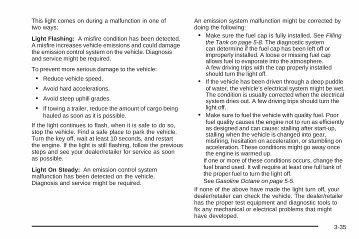
This light comes on during a malfunction in one oftwo ways:
Light Flashing: A misfire condition has been detected.A misfire increases vehicle emissions and could damagethe emission control system on the vehicle. Diagnosisand service might be required.
To prevent more serious damage to the vehicle:
• Reduce vehicle speed.
• Avoid hard accelerations.
• Avoid steep uphill grades.
• If towing a trailer, reduce the amount of cargo beinghauled as soon as it is possible.
If the light continues to flash, when it is safe to do so,stop the vehicle. Find a safe place to park the vehicle.Turn the key off, wait at least 10 seconds, and restartthe engine. If the light is still flashing, follow the previoussteps and see your dealer/retailer for service as soonas possible.
Light On Steady: An emission control systemmalfunction has been detected on the vehicle.Diagnosis and service might be required.
An emission system malfunction might be corrected bydoing the following:• Make sure the fuel cap is fully installed. See Filling
the Tank on page 5-8. The diagnostic systemcan determine if the fuel cap has been left off orimproperly installed. A loose or missing fuel capallows fuel to evaporate into the atmosphere.A few driving trips with the cap properly installedshould turn the light off.
• If the vehicle has been driven through a deep puddleof water, the vehicle’s electrical system might be wet.The condition is usually corrected when the electricalsystem dries out. A few driving trips should turn thelight off.
• Make sure to fuel the vehicle with quality fuel. Poorfuel quality causes the engine not to run as efficientlyas designed and can cause: stalling after start-up,stalling when the vehicle is changed into gear,misfiring, hesitation on acceleration, or stumbling onacceleration. These conditions might go away oncethe engine is warmed up.
If one or more of these conditions occurs, change thefuel brand used. It will require at least one full tank ofthe proper fuel to turn the light off.See Gasoline Octane on page 5-5.
If none of the above have made the light turn off, yourdealer/retailer can check the vehicle. The dealer/retailerhas the proper test equipment and diagnostic tools tofix any mechanical or electrical problems that mighthave developed.
3-35

Emissions Inspection and MaintenanceProgramsSome state/provincial and local governments have ormight begin programs to inspect the emission controlequipment on the vehicle. Failure to pass this inspectioncould prevent getting a vehicle registration.
Here are some things to know to help the vehicle passan inspection:
• The vehicle will not pass this inspection if the checkengine light is on with the engine running, or if thekey is in ON/RUN and the light is not on.
• The vehicle will not pass this inspection if theOBD II (on-board diagnostic) system determinesthat critical emission control systems have not beencompletely diagnosed by the system. The vehiclewould be considered not ready for inspection.This can happen if the battery has recently beenreplaced or if the battery has run down. Thediagnostic system is designed to evaluate criticalemission control systems during normal driving.This can take several days of routine driving. If thishas been done and the vehicle still does not pass theinspection for lack of OBD II system readiness, yourdealer/retailer can prepare the vehicle for inspection.
Oil Pressure Light (US-Canada)
{CAUTION:
Do not keep driving if the oil pressure is low.The engine can become so hot that it catches fire.Someone could be burned. Check the oil as soonas possible and have the vehicle serviced.
Notice: Lack of proper engine oil maintenancecan damage the engine. The repairs would not becovered by the vehicle warranty. Always followthe maintenance schedule in this manual forchanging engine oil.
3-36

This light comes on briefly while starting the engine.If it does not, have the vehicle serviced by yourdealer/retailer. If the system is working normallythe indicator light then goes off.
If the light comes on and stays on, it means that oilis not flowing through the engine properly. The vehiclecould be low on oil and it might have some other systemproblem.
Change Engine Oil Light
If this light comes on and stays on for 30 seconds,it means that service is required for your vehicle.
A CHANGE OIL SOON message will appear on theDIC. For more information see DIC Warnings andMessages on page 3-49.
After having the oil changed you will need to reset thelight. See Engine Oil on page 5-15, and ScheduledMaintenance on page 6-4 for more information.
Security Light
For information regardingthis light and the vehicle’ssecurity system, seeContent Theft-Deterrenton page 2-17, andPASS-Key® III+ ElectronicImmobilizer Operation onpage 2-18.
Fog Lamp Light
The fog lamp light comeson when the fog lamps arein use.
The light goes out when the fog lamps are turned off.See Fog Lamps on page 3-14 for more information.
3-37

Cruise Control Light
The cruise control lightcomes on whenever thecruise control is set.
The light goes out when the cruise control is turned off.See Cruise Control on page 3-10 for more information.
Reduced Engine Power Light
Your vehicle has areduced engine powerlight.
This light, along with the service vehicle soon light,will be displayed when a noticeable reduction inthe vehicle’s performance may occur. Stop the vehicleand turn off the ignition. Wait for 10 seconds and restart
your vehicle. This may correct the condition.See Service Vehicle Soon Light on page 3-40for more information.
The vehicle may be driven at a reduced speed whenthe reduced engine power light is on, but accelerationand speed may be reduced. The performance maybe reduced until the next time you drive your vehicle.If this light stays on, see your dealer/retailer as soonas possible for diagnosis and repair.
Highbeam On Light
This light comes on whenthe high-beam headlampsare in use.
See Headlamp High/Low-Beam Changer on page 3-8for more information.
3-38

Service All-Wheel Drive Light
This light is located in thecenter of your instrumentpanel cluster.
This light and the SERVICE ALL WHEEL DRIVEmessage in the Driver Information Center (DIC) willcome on and stay on to indicate that there may be aproblem with the drive system and service is required.See All-Wheel Drive (AWD) System on page 4-8and DIC Warnings and Messages on page 3-49for more information.
All-Wheel Drive Disabled Light
This light will come onwhen the rear drive systemis overheating.
An ALL WHEEL DRIVE OFF message will appear in theDriver Information Center (DIC) too. This light will turn offwhen the rear drive system cools down. If this light stayson for a while, you need to reset the light. To reset thelight, turn the ignition off and then back on again. If thelight stays on, see your dealer/retailer right away.
See All-Wheel Drive on page 5-41 and DIC Warningsand Messages on page 3-49 for more information.
3-39

Gate Ajar Light
If this light comes on, yourliftgate is not completelyclosed. Driving with theliftgate open can causecarbon monoxide (CO)to enter the vehicle.
See Engine Exhaust on page 2-35 for more information.
Door Ajar Light
This light will come onwhen a door is open.Before driving, checkthat all doors are properlyclosed.
Service Vehicle Soon Light
This light, comes on ifa condition exists thatrequires the vehicle tobe taken in for service.
If the light comes on, see your dealer/retailer for serviceas soon as possible.
3-40

Fuel Gage
When the ignition is on,the fuel gage tells youabout how much fuel youhave left in your tank.
When the indicator nears empty, the low fuel light willcome on. You still have a little fuel left, but you should getmore soon. See Low Fuel Warning Light on page 3-41 formore information.
Here are four things that some owners ask about.None of these show a problem with your fuel gage:
• At the service station, the fuel pump shuts off beforethe gage reads full.
• It takes a little more or less fuel to fill up than thegage indicated. For example, the gage may haveindicated the tank was half full, but it actually tooka little more or less than half the tank’s capacityto fill the tank.
• The gage moves a little when you turn a corner orspeed up.
• The gage takes a few seconds to stabilize after theignition is turned on, and will go back to emptywhen you turn the ignition off.
For your fuel tank capacity, see Capacities andSpecifications on page 5-97.
Low Fuel Warning Light
This light is located inthe fuel gage. For moreinformation see Fuel Gageon page 3-41.
This light comes on when the fuel tank is low on fuel.When you add fuel the light should go off. If it does not,have your vehicle serviced.
A “Fuel Level LOW” message also appears in the DriverInformation Center (DIC). See Fuel Gage on page 3-41for more information.
3-41

Driver Information Center (DIC)Your vehicle has a Driver Information Center (DIC).All messages will appear in the DIC display locatedin the center of the instrument panel cluster. The DICbuttons are located on the center of the instrument panel.The DIC comes on when the ignition is on. After a shortdelay, the DIC will display the information that waslast displayed before the engine was turned off.The DIC displays trip, fuel, and vehicle systeminformation, and warning messages if a system problemis detected. The top of the DIC display shows the shiftlever position indicator. See Automatic TransmissionOperation (3.4L V6 with 5-Speed) on page 2-24 orAutomatic Transmission Operation (3.6L V6 with6-Speed) on page 2-27 for more information.If your vehicle has these feature, the DIC also displaysthe compass direction and the outside air temperaturewhen viewing the trip and fuel information. If there is aproblem with the system that controls the temperaturedisplay, the numbers will be replaced with dashes. If thisoccurs, have the vehicle serviced by your dealer/retailer.If an abnormal temperature reading is displayed for anextended period of time, consult your dealer/retailer.Under certain circumstances, especially when the engineis idling, a delay updating the temperature display isnormal.The DIC also allows some features to be personalized.See DIC Vehicle Personalization on page 3-57 formore information.
DIC Operation and DisplaysThe DIC has different displays which can be accessedby pressing the DIC buttons located on the centerof the instrument panel.
DIC Buttons
The buttons are the trip/fuel, vehicle information, andset/reset buttons. The button functions are detailedin the following pages.
3 (Trip/Fuel): Press this button to scroll throughthe trip and fuel displays. See “Trip/Fuel Menu Items”following for more information on these displays.
3-42

T (Vehicle Information): Press this button toscroll through the vehicle information displays andto personalize the feature settings on your vehicle.See “Vehicle Information Menu Items” following andDIC Vehicle Personalization on page 3-57 for moreinformation on these displays.
V (Set/Reset): Press this button to set or reset certainfunctions and to turn off or acknowledge messageson the DIC.
Trip/Fuel Menu Items
3 (Trip/Fuel): Press this button to scroll throughthe following displays:
ODOMETERPress the trip/fuel button until ODOMETER displays.This display shows the distance the vehicle has beendriven in either miles (mi) or kilometers (km). This displaywill also show the outside air temperature in eitherdegrees Fahrenheit (°F) or degrees Celsius (°C).
To change the DIC display to English or metric units,see “UNITS” later in this section.
TRIPPress the trip/fuel button until TRIP displays. Thisdisplay shows the current distance traveled in eithermiles (mi) or kilometers (km) since the last reset for thetrip odometer. This display will also show the outsideair temperature in either degrees Fahrenheit (°F)or degrees Celsius (°C).
The trip odometer can be reset to zero by pressing theset/reset button while the trip odometer is displayed.
AVG (Average) SPD (Speed)Press the trip/fuel button until AVG (Average) SPD(Speed) displays. This display shows the average speedof the vehicle in miles per hour (mph) or kilometers perhour (km/h). This average is calculated based on thevarious vehicle speeds recorded since the last reset ofthis value. To reset the value, press and hold the set/reset button. The display will return to zero.
AVG (Average) ECON (Economy)Press the trip/fuel button until AVG (Average)ECON (Economy) displays. This display shows theapproximate average miles per gallon (mpg) or litersper 100 kilometers (L/100 km). This number is calculatedbased on the number of mpg (L/100 km) recorded sincethe last time this menu item was reset. To reset thisdisplay, press and hold the set/reset button. The displaywill return to zero.
3-43

RANGEPress the trip/fuel button until RANGE displays.This display shows the approximate number ofremaining miles (mi) or kilometers (km) the vehiclecan be driven without refueling.
The fuel range estimate is based on an average ofthe vehicle’s fuel economy over recent driving historyand the amount of fuel remaining in the fuel tank.This estimate will change if driving conditions change.For example, if driving in traffic and making frequentstops, this display may read one number, but ifthe vehicle is driven on a freeway, the number maychange even though the same amount of fuel is in thefuel tank. This is because different driving conditionsproduce different fuel economies. Generally, freewaydriving produces better fuel economy than city driving.
If your vehicle is low on fuel, the FUEL LEVEL LOWmessage will be displayed. See “FUEL LEVEL LOW”under DIC Warnings and Messages on page 3-49for more information.
Blank DisplayThis display shows no information.
Vehicle Information Menu Items
T (Vehicle Information): Press this button to scrollthrough the following displays:
OIL LIFEPress the vehicle information button until OIL LIFEREMAINING displays. This display shows an estimateof the oil’s remaining useful life. If you see 99% OIL LIFEREMAINING on the display, that means 99% of thecurrent oil life remains. The engine oil life system will alertyou to change the oil on a schedule consistent with yourdriving conditions.
When the remaining oil life is low, the CHANGEENGINE OIL SOON message will appear on the displayalong with the Change Engine Oil Light on the instrumentpanel cluster. See “CHANGE ENGINE OIL SOON” underDIC Warnings and Messages on page 3-49 and ChangeEngine Oil Light on page 3-37. You should change theoil as soon as possible. See Engine Oil on page 5-15.In addition to the engine oil life system monitoring theoil life, additional maintenance is recommended in theMaintenance Schedule in this manual. See ScheduledMaintenance on page 6-4 for more information.
3-44

Remember, you must reset the OIL LIFE yourselfafter each oil change. It will not reset itself. Also, becareful not to reset the OIL LIFE accidentally at anytime other than when the oil has just been changed.It cannot be reset accurately until the next oil change.To reset the engine oil life system, see Engine OilLife System on page 5-18.
UNITSPress the vehicle information button until UNITSdisplays. This display allows you to select betweenEnglish or Metric units of measurement. Once in thisdisplay, press the set/reset button to select betweenENGLISH or METRIC units.
FRONT TIRES or REAR TIRESThe pressure for each tire can be viewed in the DIC.The tire pressure will be shown in either pounds persquare inch (psi) or kilopascals (kPa). Press the vehicleinformation button until the DIC displays FRONT TIRESPSI (kPa) LF ## RF ##. Press the vehicle informationbutton again until the DIC displays REAR TIRES PSI(kPa) LR ## RR ##.
If a low or high tire pressure condition is detected bythe system while driving, a message advising youto check the pressure in a specific tire will appear in
the display. See Inflation - Tire Pressure on page 5-55and DIC Warnings and Messages on page 3-49 formore information.
If the tire pressure display shows dashes instead ofa value, there may be a problem with your vehicle. If thisconsistently occurs, see your dealer/retailer for service.
BATTERYPress the vehicle information button until BATTERYdisplays. This display shows the current battery voltage.If the voltage is normal, the display will show NORMAL.If the voltage is low or high, the display will show LOW orHIGH. Your vehicle’s charging system regulates voltagebased on the state of the battery. The battery voltagemay fluctuate when viewing this information on the DIC.This is normal. See Charging System Light on page 3-30for more information.
If there is a problem with the battery charging system,the DIC will display SERVICE BATTERY CHARGINGSYSTEM. See “SERVICE BATTERY CHARGINGSYSTEM” under DIC Warnings and Messages onpage 3-49. Also, see Electric Power Managementon page 3-16 for more information.
3-45

LEARN REMOTE KEYThis display allows you to match Remote KeylessEntry (RKE) transmitters to your vehicle. To matchan RKE transmitter to your vehicle:
1. Make sure the vehicle is in P (Park).
2. Press the vehicle information button until LEARNREMOTE KEY PRESS V TO BEGIN displays.
3. Press the set/reset button until REMOTE KEYLEARNING ACTIVE is displayed.
4. Press and hold the lock and unlock buttons onthe first transmitter at the same time for about15 seconds.A chime will sound indicating that the transmitter ismatched.
5. To match additional transmitters at this time, repeatStep 3.Each vehicle can have a maximum of fourtransmitters matched to it.
6. To exit the programming mode, you must cycle thekey to LOCK/OFF.
CALIBRATE COMPAS (Compass)Your vehicle may have this feature. The compass canbe manually calibrated. To calibrate the compassthrough the DIC, see DIC Compass on page 3-47.
CHANGE COMPASS ZONEYour vehicle may have this feature. To change thecompass zone through the DIC, see DIC Compasson page 3-47.
Blank DisplayThis display shows no information.
FEATURE SETTNGS (Settings):PRESS V TO SELCT (Select)This display allows you to personalize the featuresettings on your vehicle. See DIC Vehicle Personalizationon page 3-57 for more information.
3-46

DIC CompassYour vehicle may have a compass in the DriverInformation Center (DIC).
Compass ZoneThe zone is set to zone eight upon leaving the factory.Your dealer/retailer will set the correct zone for yourlocation.
Under certain circumstances, such as during a longdistance cross-country trip or moving to a new stateor province, it will be necessary to compensate forcompass variance by resetting the zone through theDIC if the zone is not set correctly.
Compass variance is the difference between the earth’smagnetic north and true geographic north. If the compassis not set to the zone where you live, the compass maygive false readings. The compass must be set to thevariance zone in which the vehicle is traveling.
To adjust for compass variance, use the followingprocedure:
Compass Variance (Zone) Procedure1. Do not set the compass zone when the vehicle is
moving. Only set it when the vehicle is in P (Park).Press the vehicle information button untilPRESS V TO CHANGE COMPASS ZONE displays.
2. Find the vehicle’s current location and variancezone number on the map.Zones 1 through 15 are available.
3. Press the set/reset button to scroll through andselect the appropriate variance zone.
4. Press the trip/fuel button until the vehicle heading,for example, N for North, is displayed in the DIC.
5. If calibration is necessary, calibrate the compass.See “Compass Calibration Procedure” following.
3-47

Compass CalibrationThe compass can be manually calibrated. Only calibratethe compass in a magnetically clean and safe location,such as an open parking lot, where driving the vehiclein circles is not a danger. It is suggested to calibrateaway from tall buildings, utility wires, manhole covers,or other industrial structures, if possible.
If CAL should ever appear in the DIC display, thecompass should be calibrated.
If the DIC display does not show a heading, forexample, N for North, or the heading does not changeafter making turns, there may be a strong magnetic fieldinterfering with the compass. Such interference may becaused by a magnetic CB or cell phone antenna mount,a magnetic emergency light, magnetic note pad holder,or any other magnetic item. Turn off the vehicle, movethe magnetic item, then turn on the vehicle and calibratethe compass.
To calibrate the compass, use the following procedure:
Compass Calibration Procedure1. Before calibrating the compass, make sure the
compass zone is set to the variance zone inwhich the vehicle is located. See “CompassVariance (Zone) Procedure” earlier in this section.Do not operate any switches such as window,sunroof, climate controls, seats, etc. duringthe calibration procedure.
2. Press the vehicle information button untilPRESS V TO CALIBRATE COMPAS (Compass)displays.
3. Press the set/reset button to start the compasscalibration.
4. The DIC will display CALIBRATING: DRIVE INCIRCLES. Drive the vehicle in tight circles at lessthan 5 mph (8 km/h) to complete the calibration.The DIC will display CALIBRATION COMPLETEfor a few seconds when the calibration is complete.The DIC display will then return to theprevious menu.
3-48

DIC Warnings and MessagesMessages are displayed on the DIC to notify the driverthat the status of the vehicle has changed and thatsome action may be needed by the driver to correctthe condition. Multiple messages may appear oneafter another.
Some messages may not require immediate action,but you can press the set/reset button to acknowledgethat you received the messages and to clear them fromthe display. Pressing any of the DIC buttons alsoacknowledge and clear any messages.
Some messages cannot be cleared from the DICdisplay because they are more urgent. These messagesrequire action before they can be cleared. You shouldtake any messages that appear on the display seriouslyand remember that clearing the messages will onlymake the messages disappear, not correct the problem.
The following are the possible messages that can bedisplayed and some information about them.
ALL WHEEL DRIVE OFFIf your vehicle has the All-Wheel Drive (AWD) system,this message displays along with the All-Wheel DriveDisabled light when the rear drive system is overheating.This message turns off when the rear drive system coolsdown. If the warning message stays on for a while, youneed to reset the warning message. To reset the warningmessage, turn the ignition off and then back on again.If the message stays on, see your dealer/retailer rightaway. See All-Wheel Drive (AWD) System on page 4-8and All-Wheel Drive Disabled Light on page 3-39 formore information.
BATTERY SAVER ACTIVEThis message displays when the charging systemdetects that the battery is being drained. You may noticethat the vehicle attempts to reduce the drain for youby turning off accessories, such as interior fans, reardefogger, and heated seats. Turn off all accessories.If the vehicle is not running, start and run the enginefor at least 10 minutes to allow the battery to recharge.If the engine is running and the condition persists, seeyour dealer/retailer. See Electric Power Managementon page 3-16 for more information.
3-49

CALIBRATING: DRIVE IN CIRCLESThis message displays when calibrating the compass.Drive the vehicle in circles at less than 5 mph (8 km/h)to complete the calibration. See DIC Compass onpage 3-47 for more information.
CALIBRATION COMPLETEThis message displays when the compass calibrationis complete. See DIC Compass on page 3-47 formore information.
CHANGE ENGINE OIL SOONThis message displays and the Change Engine Oil Lightin the instrument panel cluster turns on when serviceis required for the vehicle. See your dealer/retailer.See Change Engine Oil Light on page 3-37, Engine Oilon page 5-15 and Scheduled Maintenance on page 6-4for more information.
Acknowledging this message will not reset the OIL LIFEREMAINING display. That must be done at the OIL LIFEscreen under the vehicle information menu. See “OILLIFE” under DIC Operation and Displays on page 3-42and Engine Oil Life System on page 5-18 for moreinformation.
CHECK TIRE PRESSUREThis message displays when the pressure in oneor more of the vehicle’s tires needs to be checked.This message also displays LEFT FRONT, RIGHT FRNT(Front), LEFT REAR, or RIGHT REAR to indicate whichtire needs to be checked. You can receive more thanone tire pressure message at a time. To read the othermessages that may have been sent at the same time,press the set/reset button. If a tire pressure messageappears on the DIC, stop as soon as you can. Have thetire pressures checked and set to those shown on theTire Loading Information label. See Tires on page 5-48,Loading the Vehicle on page 4-20, and Inflation - TirePressure on page 5-55. The DIC also shows the tirepressure values. See DIC Operation and Displays onpage 3-42. If the tire pressure is low, the low tire pressurewarning light comes on. See Tire Pressure Light onpage 3-33.
DRIVER DOOR OPENThis message displays when the driver door is notclosed properly. Close the door completely.
3-50

ENGINE HOT A/C(Air Conditioning) OFFThis message displays when the engine coolantbecomes hotter than the normal operating temperature.To avoid added strain on a hot engine, the airconditioning compressor is automatically turned off.When the coolant temperature returns to normal,the A/C operation automatically resumes. You cancontinue to drive your vehicle.
ENGINE OVERHEATD (Overheated)IDLE ENGINE
Notice: If you drive your vehicle while the engineis overheating, severe engine damage may occur.If an overheat warning appears on the instrumentpanel cluster and/or DIC, stop the vehicle as soon aspossible. Do not increase the engine speed abovenormal idling speed. See Engine Overheatingon page 5-28 for more information.
This message displays when the engine coolanttemperature is too hot. Stop and allow the vehicle toidle until it cools down.
ENGINE OVRHEATD (Overheated)STOP ENGINE
Notice: If you drive your vehicle while the engineis overheating, severe engine damage may occur.If an overheat warning appears on the instrumentpanel cluster and/or DIC, stop the vehicle as soonas possible. See Engine Overheating on page 5-28for more information.
This message displays along with a continuous chimewhen the engine has overheated. Stop and turn theengine off immediately to avoid severe engine damage.See Engine Overheating on page 5-28.
ENGINE POWER IS REDUCEDThis message displays when the vehicle’s enginepower is reduced. Reduced engine power can affectthe vehicle’s ability to accelerate. If this message is on,but there is no reduction in performance, proceed to yourdestination. The performance may be reduced the nexttime the vehicle is driven. The vehicle may be driven at areduced speed while this message is on, but accelerationand speed may be reduced. Anytime this message stayson, the vehicle should be taken to your dealer/retailer forservice as soon as possible.
3-51

FUEL LEVEL LOWThis message displays and the Low Fuel WarningLight in the instrument panel cluster comes on whenyour vehicle is low on fuel. Refill the fuel tank as soonas possible. See Fuel Gage on page 3-41, Low FuelWarning Light on page 3-41, and Filling the Tank onpage 5-8 for more information.
HOOD OPENThis message displays on some vehicles when thehood is not closed properly. Close the hood completely.See Hood Release on page 5-11.
ICE POSSIBLE DRIVE WITH CAREThis message displays when the outside air temperatureis cold enough to create icy road conditions. Adjustyour driving accordingly.
LIFTGATE OPENThis message displays when the liftgate is not closedcompletely. Close the liftgate completely. See Liftgateon page 2-12.
OIL PRSSURE (Pressure) LOW STOPENGINE
Notice: If you drive your vehicle while the engineoil pressure is low, severe engine damage mayoccur. If a low oil pressure warning appears on theDriver Information Center (DIC), stop the vehicleas soon as possible. Do not drive the vehicle untilthe cause of the low oil pressure is corrected.See Engine Oil on page 5-15 for more information.
This message displays when the vehicle’s engineoil pressure is low. The oil pressure light also appearson the instrument panel cluster. See Oil PressureLight (US-Canada) on page 3-36.
Stop the vehicle immediately, as engine damage canresult from driving a vehicle with low oil pressure.Have the vehicle serviced by your dealer/retailer assoon as possible when this message is displayed.
PASSENGER DOOR FRONT/REAR OPENThis message displays when one or more of thepassenger doors are not closed properly. Close thedoors completely.
3-52

REMOTE KEY LEARNING ACTIVEThis message displays while you are matching aRemote Keyless Entry (RKE) transmitter to your vehicle.See “LEARN REMOTE KEY” under DIC Operationand Displays on page 3-42 for more information.
SERVICE A/C (Air Conditioning)SYSTEMThis message displays when there is a problemdetected in the air conditioning system. Have thevehicle serviced by your dealer/retailer.
SERVICE AIR BAGThis message displays when there is a problem withthe airbag system. Have your vehicle serviced by yourdealer/retailer immediately. See Airbag ReadinessLight on page 3-28 for more information.
SERVICE ALL WHEEL DRIVEIf your vehicle has the All-Wheel Drive (AWD)system, this message displays along with the serviceall-wheel drive light if a problem occurs with this system.See Service All-Wheel Drive Light on page 3-39. If thismessage appears, stop as soon as possible and turnoff the vehicle. Restart the vehicle and check for the
message on the DIC display. If the message is stilldisplayed or appears again when you begin driving, theAWD system needs service. See your dealer/retailer.
SERVICE BATTERY CHARGINGSYSTEMThis message displays when there is a problem with thegenerator and battery charging systems. Driving withthis problem could drain the vehicle’s battery. Turn off allunnecessary accessories. Stop and turn off the vehicleas soon as it is safe to do so. Have the electricalsystem checked by your dealer/retailer immediately.
Connecting a battery charger to your vehicle while theignition is in any position other than LOCK/OFF maycause this message to appear. If you need to chargeyour vehicle, make sure that the key is in LOCK/OFFor out of the ignition during charging.
SERVICE BRAKE SYSTEMThis message displays and a chime sounds when thebrake fluid level is low. The brake system warninglight also appears on the instrument panel cluster whenthis message appears on the DIC. See Brake SystemWarning Light on page 3-30. Have the brake systemserviced by your dealer/retailer as soon as possible.
3-53

SERVICE POWER STEERINGOn some vehicles, this message displays when aproblem is detected with the power steering system.When this message is displayed, you may noticethat the effort required to steer the vehicle increasesor feels heavier, but you will still be able to steerthe vehicle. Have your vehicle serviced by yourdealer/retailer immediately.
SERVICE STABILITRAKThis message displays if there has been a problemdetected with the StabiliTrak® System. A warninglight also appears on the instrument panel cluster.See Traction Control System (TCS) Warning Lighton page 3-32. See StabiliTrak® System on page 4-6for more information.
If this message turns on while you are driving, pulloff the road as soon as possible and stop carefully.Try resetting the system by turning the ignition off andthen back on. If this message still stays on or turnsback on again while you are driving, your vehicle needsservice. Have the StabiliTrak® System inspected byyour dealer/retailer as soon as possible.
SERVICE THEFT DETERRENT SYSTEMThis message displays when there is a problem withthe theft-deterrent system. A fault has been detected inthe system which means that the system is disabledand it is not protecting the vehicle. The vehicle usuallyrestarts; however, you may want to take the vehicleto your dealer/retailer before turning off the engine.See PASS-Key® III+ Electronic Immobilizer Operationon page 2-18 for more information.
SERVICE TIRE MONITOR SYSTEMThis message displays if a part on the Tire PressureMonitor System (TPMS) is not working properly. The tirepressure light also flashes and then remains on duringthe same ignition cycle. See Tire Pressure Light onpage 3-33. Several conditions may cause this messageto appear. See Tire Pressure Monitor Operation onpage 5-59 for more information. If the warning comes onand stays on, there may be a problem with the TPMS.See your dealer/retailer.
3-54

SERVICE TRACTION CONTROLThis message displays when the Traction ControlSystem (TCS) is not functioning properly. A warninglight also appears on the instrument panel cluster.See Traction Control System (TCS) Warning Lighton page 3-32 and Traction Control System (TCS) onpage 4-7 for more information. Have the TCS servicedby your dealer/retailer as soon as possible.
SERVICE VEHICLE SOONThis message displays when a non-emissions relatedmalfunction occurs. Have the vehicle serviced byyour dealer/retailer as soon as possible.
STABILITRAK NOT READYThis message may display and a warning light on theinstrument panel cluster may be on after first driving thevehicle and exceeding 30 mph (48 km/h) for 30 seconds.See Traction Control System (TCS) Warning Light onpage 3-32. The StabiliTrak® System is not functionaluntil the light has turned off. See StabiliTrak® Systemon page 4-6 for more information.
STABILITRAK OFFThis message displays any time the StabiliTrak®
System turns off. When this message has beendisplayed, StabiliTrak® is no longer available to assistyou with directional control of the vehicle. Adjust yourdriving accordingly. See StabiliTrak® System onpage 4-6.
This message displays only while the ignition is inON/RUN.
Any of the following conditions may cause theStabiliTrak® System to turn off:
• The StabiliTrak® System is turned off bypressing and holding the traction control button.See StabiliTrak® System on page 4-6 for moreinformation.
• The battery is low.
• There is a StabiliTrak® System failure. See yourdealer/retailer for service.
3-55

STARTING DISABLD (Disabled)SERVICE THRTTLE (Throttle)This message displays if the starting of the engine isdisabled due to the electronic throttle control system.Have your vehicle serviced by your dealer/retailerimmediately.
This message only appears while the ignition is inON/RUN, and will not disappear until the problemis resolved.
This message cannot be acknowledged.
THEFT ATTEMPTEDThis message displays if the content theft-deterrentsystem has detected a break-in attempt while you wereaway from your vehicle. See Content Theft-Deterrenton page 2-17 for more information.
TIRE LEARNING ACTIVEThis message displays when the Tire Pressure MonitorSystem (TPMS) is re-learning the tire positions onyour vehicle. The tire positions must be re-learnedafter rotating the tires or after replacing a tire orsensor. See Tire Inspection and Rotation on page 5-62,Tire Pressure Monitor System on page 5-57, andInflation - Tire Pressure on page 5-55 for moreinformation.
TRACTION CONTROL OFFThis message displays when the Traction ControlSystem (TCS) turns off. See Traction ControlSystem (TCS) on page 4-7 for more information.
This message only displays while the ignition is inON/RUN and disappears after 10 seconds, unless itis acknowledged or an urgent warning appears.
Any of the following conditions may cause the TCS toturn off:
• The TCS is turned off by pressing the tractioncontrol button. See Traction Control System (TCS)on page 4-7 for more information.
• The battery is low.
• There is a TCS failure. See your dealer/retailer forservice.
TRACTION CONTROL ONThis message displays when the Traction ControlSystem (TCS) turns on. See Traction Control System(TCS) on page 4-7 for more information.
3-56

TURN SIGNAL ONThis message displays as a reminder to turn off theturn signal if you drive your vehicle for more than about0.75 mile (1.2 km) with a turn signal on. See TurnSignal/Multifunction Lever on page 3-7.
This message displays and a chime sounds onlywhen the ignition is in ON/RUN. The message will notdisappear until the turn signal is manually turned off,or a turn is completed.
DIC Vehicle PersonalizationYour vehicle has personalization capabilities that allowyou to program certain features to one preferred setting.
All of the personalization options may not be availableon your vehicle. Only the options available will bedisplayed on the DIC.
The default settings for the personalization featureswere set when your vehicle left the factory, butmay have been changed from their default statesince then.
The personalization preferences are automaticallyrecalled.
To change personalization preferences, use thefollowing procedure.
Entering the Feature Settings Menu1. Turn the ignition on and place the vehicle in
P (Park).To avoid excessive drain on the battery, it isrecommended that the headlamps are turned off.
2. Press the vehicle information button until FEATURESETTNGS (Settings): PRESS V TO SELCT (Select)appears on the DIC display.
3. Press the set/reset button to enter the featuresettings menu.If the menu is not available, FEATURE SETTNGS(Settings): AVAILABLE IN PRK (Park) will display.Before entering the menu, make sure the vehicle isin P (Park).
Feature Settings Menu ItemsThe following are personalization features that allow youto program settings to the vehicle:
DISPLAY ENGLISHThis feature will only display if a language other thanEnglish has been set. This feature allows you to changethe language in which the DIC messages appear toEnglish.Press the vehicle information button until thePRESS V TO DISPLAY ENGLISH screen appearson the DIC display. Press the set/reset button to displayall DIC messages in English.
3-57

DISPLAY LANG. (Language)This feature allows you to select the language in whichthe DIC messages will appear.
Press the vehicle information button until DISPLAYLANG. (Language) appears on the DIC display. Pressthe set/reset button to access the settings for this feature.Then press the vehicle information button to scrollthrough the following settings:
ENGLISH (default): All messages will appear inEnglish.
FRENCH: All messages will appear in French.
SPANISH: All messages will appear in Spanish.
NO CHANGE: No change will be made to this feature.The current setting will remain.
To select a setting, press the set/reset button while thedesired setting is displayed on the DIC.
AUTO LOCKThis feature allows you to select when the vehicle’sdoors will automatically lock. See ProgrammableAutomatic Door Locks on page 2-11 for moreinformation.
Press the vehicle information button until AUTO LOCKappears on the DIC display. Press the set/reset buttonto access the settings for this feature. Then press thevehicle information button to scroll through the followingsettings:
OUT OF PARK (default): The vehicle’s doorsautomatically lock when the doors are closed andthe vehicle is shifted out of P (Park).
AT SPEED: The vehicle’s doors automatically lockwhen the vehicle speed is above 5 mph (8 km/h)for three seconds.
NO CHANGE: No change will be made to this feature.The current setting will remain.
To select a setting, press the set/reset button while thedesired setting is displayed on the DIC.
3-58

AUTO UNLOCKThis feature allows you to select whether or not toturn off the automatic door unlocking feature. It alsoallows you to select which doors and when the doorswill automatically unlock. See Programmable AutomaticDoor Locks on page 2-11 for more information.
Press the vehicle information button until AUTOUNLOCK appears on the DIC display. Press theset/reset button to access the settings for this feature.Then press the vehicle information button to scrollthrough the following settings:
OFF: None of the doors will automatically unlock.
DRIVER KEY OUT: Only the driver’s door will unlockwhen the key is taken out of the ignition.
DRIVER IN PARK: Only the driver’s door will unlockwhen the vehicle is shifted into P (Park).
ALL AT KEY OUT: All of the doors will unlock whenthe key is taken out of the ignition.
ALL IN PARK (default): All of the doors will unlockwhen the vehicle is shifted into P (Park).
NO CHANGE: No change will be made to this feature.The current setting will remain.
To select a setting, press the set/reset button while thedesired setting is displayed on the DIC.
REMOTE LOCKThis feature allows you to select the type of feedbackyou will receive when locking the vehicle with theRemote Keyless Entry (RKE) transmitter. You will notreceive feedback when locking the vehicle with the RKEtransmitter if any of the doors are open. See RemoteKeyless Entry (RKE) System Operation on page 2-5for more information.Press the vehicle information button until REMOTELOCK appears on the DIC display. Press the set/resetbutton to access the settings for this feature. Then pressthe vehicle information button to scroll through thefollowing settings:
HORN/LIGHTS OFF: There will be no feedback whenyou press the lock button on the RKE transmitter.
LIGHTS ONLY: The exterior lamps will flash when youpress the lock button on the RKE transmitter.
HORN CHIRP ONLY: The horn will sound on thesecond press of the lock button on the RKE transmitter.
HORN/LIGHTS ON (default): The exterior lampswill flash when you press the lock button on the RKEtransmitter, and the horn will sound when the lock buttonis pressed again within five seconds of the previouscommand.
NO CHANGE: No change will be made to this feature.The current setting will remain.
3-59
To select a setting, press the set/reset button while thedesired setting is displayed on the DIC.
REMOTE UNLOCKThis feature allows you to select the type of feedbackyou will receive when unlocking the vehicle with theRKE transmitter. You will not receive feedback whenunlocking the vehicle with the RKE transmitter ifthe doors are open. See Remote Keyless Entry (RKE)System Operation on page 2-5 for more information.
Press the vehicle information button until REMOTEUNLOCK appears on the DIC display. Press theset/reset button to access the settings for this feature.Then press the vehicle information button to scrollthrough the following settings:
LIGHTS OFF: The exterior lamps will not flash whenyou press the unlock button on the RKE transmitter.
LIGHTS ON (default): The exterior lamps willflash when you press the unlock button on theRKE transmitter.
NO CHANGE: No change will be made to this feature.The current setting will remain.
To select a setting, press the set/reset button while thedesired setting is displayed on the DIC.
DELAY LOCKThis feature allows you to select whether or not thelocking of the vehicle’s doors and liftgate will be delayed.When locking the doors and liftgate with the power doorlock switch and a door or the liftgate is open, this featurewill delay locking the doors and liftgate until five secondsafter the last door is closed. You will hear three chimesto signal that the delayed locking feature is in use.The key must be out of the ignition for this feature towork. You can temporarily override delayed locking bypressing the power door lock switch twice or the lockbutton on the RKE transmitter twice. See DelayedLocking on page 2-10 for more information.Press the vehicle information button until DELAY LOCKappears on the DIC display. Press the set/reset buttonto access the settings for this feature. Then press thevehicle information button to scroll through the followingsettings:
LOCK DELAY OFF: There will be no delayed lockingof the vehicle’s doors.
LOCK DELAY ON (default): The doors will not lockuntil five seconds after the last door or the liftgateis closed.
NO CHANGE: No change will be made to this feature.The current setting will remain.To select a setting, press the set/reset button while thedesired setting is displayed on the DIC.
3-60

EXIT LIGHTNG (Lighting)This feature allows you to select the amount of time youwant the exterior lamps to remain on when it is darkenough outside. This happens after the key is turnedfrom ON/RUN to LOCK/OFF.
Press the vehicle information button until EXITLIGHTNG (Lighting) appears on the DIC display.Press the set/reset button to access the settingsfor this feature. Then press the vehicle informationbutton to scroll through the following settings:
OFF: The exterior lamps will not turn on.
30 SECONDS (default): The exterior lamps will stay onfor 30 seconds.
1 MINUTE: The exterior lamps will stay on forone minute.
2 MINUTES: The exterior lamps will stay on fortwo minutes.
NO CHANGE: No change will be made to this feature.The current setting will remain.
To select a setting, press the set/reset button while thedesired setting is displayed on the DIC.
APPRCH (Approach) LIGHTNG (Lighting)This feature allows you to select whether or not tohave the exterior lights turn on briefly during low lightperiods after unlocking the vehicle using the RKEtransmitter.
Press the vehicle information button until APPRCH(Approach) LIGHTNG (Lighting) appears on the DICdisplay. Press the set/reset button to access the settingsfor this feature. Then press the vehicle information buttonto scroll through the following settings:
OFF: The exterior lights will not turn on when youunlock the vehicle with the RKE transmitter.
ON (default): If it is dark enough outside, the exteriorlights will turn on briefly when you unlock the vehiclewith the RKE transmitter.
The lights will remain on for 20 seconds or until the lockbutton on the RKE transmitter is pressed, or the vehicle isno longer off. See Remote Keyless Entry (RKE) SystemOperation on page 2-5 for more information.
NO CHANGE: No change will be made to this feature.The current setting will remain.
To select a setting, press the set/reset button while thedesired setting is displayed on the DIC.
3-61

CHIME VOLUMEThis feature allows you to select the volume level of thechime.
Press the vehicle information button until CHIMEVOLUME appears on the DIC display. Press theset/reset button to access the settings for this feature.Then press the vehicle information button to scrollthrough the following settings:
NORMAL: The chime volume will be set to a normallevel.
LOUD: The chime volume will be set to a loud level.
NO CHANGE: No change will be made to this feature.The current setting will remain.
There is no default for chime volume. The volume willstay at the last known setting.
To select a setting, press the set/reset button while thedesired setting is displayed on the DIC.
REMOTE STARTIf your vehicle has this feature, it allows you to turn theremote start off or on. The remote start feature allowsyou to start the engine from outside of the vehicle usingthe RKE transmitter. See Remote Vehicle Start onpage 2-7 for more information.
Press the vehicle information button until REMOTESTART appears on the DIC display. Press the set/resetbutton to access the settings for this feature. Then pressthe vehicle information button to scroll through thefollowing settings:
OFF: The remote start feature will be disabled.
ON (default): The remote start feature will be enabled.
NO CHANGE: No change will be made to thisfeature. The current setting will remain.
To select a setting, press the set/reset button while thedesired setting is displayed on the DIC.
3-62

FACTORY SETTNGS (Settings)This feature allows you to set all of the personalizationfeatures back to their factory default settings.
Press the vehicle information button until FACTORYSETTNGS (Settings) appears on the DIC display.Press the set/reset button to access the settings forthis feature. Then press the vehicle information buttonto scroll through the following settings:
RESTORE ALL (default): The personalization featureswill be set to their factory default settings.
DO NOT RESTORE: The personalization features willnot be set to their factory default settings.
To select a setting, press the set/reset button while thedesired setting is displayed on the DIC.
FEATURE SETTNGS (Settings):PRESS V TO EXITThis feature allows you to exit the feature settings menu.
Press the vehicle information button until FEATURESETTNGS (Settings): PRESS V TO EXIT appearsin the DIC display. Press the set/reset button to exitthe menu.
If you do not exit, pressing the vehicle informationbutton again will return you to the beginning of thevehicle information menu.
Exiting the Feature Settings MenuThe feature settings menu will be exited when any ofthe following occurs:
• The vehicle is shifted out of P (Park).
• The vehicle is no longer in ON/RUN.
• The trip/fuel DIC button is pressed.
• The end of the feature settings menu is reachedand exited.
• A 40 second time period has elapsed with noselection made.
3-63

Audio System(s)Determine which radio the vehicle has and read thefollowing pages to become familiar with its features.
{CAUTION:
Taking your eyes off the road for extended periodscould cause a crash resulting in injury or death toyou or others. Do not give extended attention toentertainment tasks while driving.
This system provides access to many audio and nonaudio listings.
To minimize taking your eyes off the road while driving,do the following while the vehicle is parked:
• Become familiar with the operation and controls ofthe audio system.
• Set up the tone, speaker adjustments, and presetradio stations.
For more information, see Defensive Driving onpage 4-2.
Notice: Contact your dealer/retailer before addingany equipment.
Adding audio or communication equipment couldinterfere with the operation of the vehicle’s engine,radio, or other systems, and could damage them.Follow federal rules covering mobile radio andtelephone equipment.
The vehicle has Retained Accessory Power (RAP).With RAP, the audio system can be played even afterthe ignition is turned off. See Retained AccessoryPower (RAP) on page 2-21 for more information.
3-64

Setting the Clock
AM/FM Base Radio with a Single CDPlayerIf the vehicle has a AM/FM Base Radio with a SingleCD Player, it has a H button for setting the time.
To adjust the time:
1. Turn the radio on.
2. Press the H button until the hour begins flashingon the display. Press H a second time and theminutes begin flashing on the display.
3. While either the hour or the minutes are flashing,do one of the following to increase or decreasethe time:
• Press ¨SEEK or ©SEEK.
• Press \ FWD or s REV.
• Turn f clockwise or counter-clockwise.
4. Press H again until the clock display stops flashingto set the currently displayed time; otherwise, theflashing stops after five seconds and the currenttime displayed is automatically set.
MP3 Radios with a Single CD or aSingle CD and DVD PlayerIf the vehicle has a radio with a single CD or a CDand DVD player, it has a H button for setting the timeand date.
To adjust the time and date:
1. Turn the radio on.
2. Press G to display HR, MIN, MM, DD, YYYY (hour,minute, month, day, and year).
3. Press the pushbutton located under any one of thetabs to be changed.
4. To increase the time or date, do one of thefollowing:
• Press the pushbutton below the selected tab.
• Press ¨SEEK.
• Press \ FWD.
• Turn f clockwise.
5. To decrease the time or date, do one of thefollowing:
• Press ©SEEK.
• Press s REV.
• Turn f counter-clockwise.
3-65

To change the time default setting from 12 hour to24 hour or to change the date default setting frommonth/day/year to day/month/year:
1. Press G and then the pushbutton located under theforward arrow tab that displays on the radio screenuntil the time 12H (hour) and 24H (hour), and thedate MM/DD (month and day) and DD/MM (day andmonth) displays.
2. Press the pushbutton located under the desired tab.
3. Press G again to apply the selected default, orlet the screen time out.
MP3 Radio with a Six-Disc CD PlayerIf the vehicle has a radio with a six-disc CD player,the radio has a MENU button to set the time and date.
To set the time and date:
1. Turn the ignition key to ACC/ACCESSORY orON/RUN, then press O , to turn the radio on.
2. Press MENU.
3. Press the pushbutton below the H tab. The HR,MIN, MM, DD, YYYY displays.
4. Press the pushbutton below any one of the tabsyou want to change.
5. To increase the time or date do one of the following:• Press the pushbutton located below the
selected tab.• Press ¨SEEK, or \ FWD.
• Turn f clockwise.6. To decrease the time or date do one of the following:
• Press ©SEEK or s REV.
• Turn f counterclockwise.
The date does not automatically display. To see thedate press MENU and then softkey below the H tab whilethe radio is on. The date with display times out after afew seconds and goes back to the normal radio andtime display.To change the time default setting from 12 hour to24 hour or to change the date default setting frommonth/day/year to day/month/year:1. Press MENU, and then the pushbutton below
the H tab. The HR, MIN, MM, DD, YYYY displays.2. Press the pushbutton below the forward arrow tab.
The time 12H and 24H, and the date MM/DD/YYYY(month, day, and year) and DD/MM/YYYY(day, month, and year) displays.
3. Press the pushbutton located below the desiredoption.
4. Press MENU again to apply the selected default, orlet the screen time out.
3-66

Radio(s)
The vehicle has one of these radios as its audiosystem.If the vehicle has a Rear Seat Entertainment (RSE)system, it has a CD/DVD radio. See Rear SeatEntertainment (RSE) System on page 3-109 formore information on the vehicle’s RSE system.The DVD player is the top slot on the radio faceplate.The player can read the DTS programmed DVD Audio orDVD Video media (DTS and DTS 2.0 are trademarks ofDigital Theater Systems Inc.).Dolby is manufactured under license from DolbyLaboratories. Dolby and the double-D symbol aretrademarks of Dolby Laboratories.
Radio with CD (MP3) shown, Base Radio with CDand Radio with Six-Disc CD (MP3) similar
Radio with CD and DVD (MP3)
3-67

Radio Data System (RDS)The vehicle’s audio system may have Radio DataSystem (RDS). The RDS feature is available for useonly on FM stations that broadcast RDS information.This system relies upon receiving specific informationfrom these stations and only works when the informationis available. While the radio is tuned to an FM-RDSstation, the station name or call letters appear on thedisplay. In rare cases, a radio station may broadcastincorrect information that causes the radio features towork improperly. If this happens, contact the radio station.
Playing the Radio
O (Power/Volume): Press to turn the system onand off.
Turn clockwise or counterclockwise to increase ordecrease the volume.
Speed Compensated Volume (SCV): The vehicle’saudio system may also have Speed CompensatedVolume (SCV). While SCV is on, the radio volumeautomatically adjusts to compensate for road andwind noise as the vehicle speeds up or slows down.That way, the volume level should sound aboutthe same while driving. To activate SCV:
1. Set the radio volume to the desired level.
2. Press the MENU button to display the radiosetup menu.
3. Press the pushbutton under the AUTO VOLUM(automatic volume) tab on the radio display.
4. Press the pushbutton under the desired SpeedCompensated Volume setting (OFF, Low, Med,or High) to select the level of radio volumecompensation. The display times out afterapproximately 10 seconds. Each higher settingallows for more radio volume compensation atfaster vehicle speeds.
3-68

Finding a Station
BAND: Press to switch between AM, FM, or XM(if equipped). The selection displays.
f (Tune): Turn to select radio stations.
©SEEK ¨: Press the arrows to go to the previous orto the next station and stay there.
To scan stations, press and hold either arrow for afew seconds until a beep sounds. The radio goes toa station, plays for a few seconds, then goes to thenext station. Press either arrow again to stop scanning.
The radio only seeks and scans stations with astrong signal that are in the selected band.
4 (Information) (Base Radio with CD): Press to switchthe display between the radio station frequency and thetime. When the ignition is off, press to display the time.
4 (Information) (XM™ Satellite Radio Service, MP3/WMA, and RDS Features): Press to display additionaltext information related to the current FM-RDS or XMstation, or MP3/WMA song. A choice of additionalinformation such as: Channel, Song, Artist, and CAT(category) can appear. Continue pressing to highlightthe desired tab, or press the pushbutton positioned underany one of the tabs and the information about that tabdisplays.
When information is not available, No Info displays.
Setting Preset StationsIf the radio does not have XM™, up to 18 stations(six FM1, six FM2, and six AM) can be programmedon the six numbered pushbuttons, by performingthe following steps:
1. Turn the radio on.
2. Press BAND to select FM1, FM2, or AM.
3. Tune in the desired station.
4. Press and hold one of the six numberedpushbuttons for three seconds until a beep sounds.When that pushbutton is pressed and released,the station that was set, returns.
5. Repeat the Steps 2 through 4 for each pushbutton.
3-69

Storing a Radio Station as a FavoriteDrivers are encouraged to set up their radio stationfavorites while the vehicle is parked. Tune to favoritestations using the presets, favorites button, and steeringwheel controls, if the vehicle has them. See DefensiveDriving on page 4-2.
If the radio has XM, a maximum of 36 stations can beprogrammed as favorites using the six pushbuttonspositioned below the radio station frequency tabs andby using the radio favorites page button (FAV button).
FAV (Favorites): Press the FAV button to go throughup to six pages of favorites, each having six favoritestations available per page. Each page of favorites cancontain any combination of AM, FM, or XM (if equipped)stations. To store a station as a favorite, perform thefollowing steps:
1. Tune to the desired radio station.
2. Press the FAV button to display the page where thestation is to be stored.
3. Press and hold one of the six pushbuttons until abeep sounds. When that pushbutton is pressedand released, the station that was set, returns.
4. Repeat the steps for each pushbutton radio stationto be stored as a favorite.
The number of favorites pages can be setup usingthe MENU button. To setup the number of favoritespages, perform the following steps:
1. Press the MENU button to display the radiosetup menu.
2. Press the pushbutton located below theFAV 1-6 tab.
3. Select the desired number of favorites pagesby pressing the pushbutton located below thedisplayed page numbers.
4. Press the FAV button, or let the menu time out,to return to the original main radio screen showingthe radio station frequency tabs and to beginthe process of programming favorites for the chosenamount of numbered pages.
Setting the Tone (Bass/Treble)(Base Radio with CD)
EQ (Equalization): To adjust the bass or treble,press the f knob or EQ button until the desired tonecontrol tab displays. Turn the f knob clockwise orcounterclockwise to increase or decrease the setting.The display shows the current bass or treble level.If a station’s frequency is weak, or if there is static,decrease the treble.
3-70

Setting the Tone (Bass/Treble)
BASS/MID/TREB (Bass, Midrange, or Treble):To adjust bass, midrange, or treble, press the f knobuntil the tone control tabs display. Continue pressingto highlight the desired tab, or press the pushbuttonpositioned under the desired tab. Turn the f knobclockwise or counterclockwise to adjust the highlightedsetting. The highlighted setting can also be adjustedby pressing the SEEK arrows, \ FWD (forward)or s REV (reverse) button until the desired levelsare obtained. If a station’s frequency is weak, or ifthere is static, decrease the treble.
To quickly adjust bass, midrange, or treble to the middleposition, press the pushbutton positioned under theBASS, MID, or TREB tab for more than two seconds.A beep sounds and the level adjusts to the middleposition.
To quickly adjust all tone and speaker controls tothe middle position, press the f knob for more thantwo seconds until a beep sounds.
EQ (Equalization): Press to select preset equalizationsettings.
To return to the manual mode, press the EQ button untilManual displays or starts to manually adjust the bass,midrange, or treble by pressing the f knob.
EQ (Equalization) (Radio with CD and DVD): Pressto choose bass and treble equalization settings designedfor different types of music. The choices are pop, rock,country, talk, jazz, and classical. Selecting MANUAL orchanging bass or treble, returns the EQ to the manualbass and treble settings.
Unique EQ settings can be saved for each source.
If the radio has a Bose® audio system, the EQ settingsare either MANUAL or TALK.
Adjusting the Speakers (Balance/Fade)(Base Radio with CD)
` BAL/FADE (Balance/Fade): To adjust the balanceor fade, press the ` button or the f knob until thedesired speaker control tab displays. Turn the f knobclockwise or counterclockwise to adjust the setting.
3-71

Adjusting the Speakers (Balance/Fade)
BAL/FADE (Balance/Fade): To adjust balance or fade,press the f knob until the speaker control tabs display.Continue pressing to highlight the desired tab, or pressthe pushbutton positioned under the desired tab. Turnthe f knob clockwise or counterclockwise to adjust thehighlighted setting. The highlighted setting can alsobe adjusted by pressing the SEEK arrows, \ FWD,or s REV button until the desired levels are obtained.
To quickly adjust balance or fade to the middle position,press the pushbutton positioned under the BAL or FADEtab for more than two seconds. A beep sounds and thelevel adjusts to the middle position.
To quickly adjust all speaker and tone controls tothe middle position, press the f knob for more thantwo seconds until a beep sounds.
Finding a Category (CAT) StationIf the radio has XM, the CAT button can be used to findXM stations when the radio is in the XM mode.
CAT (Category): To find XM channels within a desiredcategory, perform the following:
1. Press the BAND button until the XM frequencyis displayed. Press the CAT button to display thecategory tabs on the radio display. Continue pressingthe CAT button until the desired category namedisplays.
• Depending on the radio, another way to navigatethe category list is to press the s REV button orthe \ FWD button.
2. Press either of the two buttons below the desiredcategory tab to immediately tune to the first XMstation associated with that category.
3. Turn the f knob, press the buttons below the rightor left arrows displayed, or press the Seek arrowsto go to the previous or to the next XM station withinthe selected category.
4. To exit the category search mode, press the FAVbutton or BAND button to display the favorites again.
3-72
Undesired XM categories can be removed throughthe setup menu. To remove an undesired category,perform the following:
1. Press the MENU button to display the radiosetup menu.
2. Press the pushbutton located below theXM CAT tab.
3. Turn the f knob to display the category to beremoved.
4. Press the pushbutton located under the Removetab until the category name along with the wordRemoved displays.
5. Repeat the steps to remove more categories.
Removed categories can be restored by pressing thepushbutton under the Add tab when a removed categorydisplays or by pressing the pushbutton under the RestoreAll tab.
Categories cannot be added or removed while thevehicle is moving faster than 5 mph (8 km/h).
Radio Messages
Calibration Error: The audio system has beencalibrated for the vehicle from the factory. If CalibrationError displays, it means that the radio has not beenconfigured properly for the vehicle and it must bereturned to your dealer/retailer for service.
Loc or Locked: This message displays when theTHEFTLOCK® system has locked up the radio.Take the vehicle to your dealer/retailer for service.
If any error occurs repeatedly or if an error cannot becorrected, contact your dealer/retailer.
XM™ Satellite Radio ServiceXM™ is a satellite radio service that is based in the48 contiguous United States and 10 Canadian provinces.XM Satellite Radio has a wide variety of programmingand commercial-free music, coast-to-coast, and indigital-quality sound. During your trial or when yousubscribe, you will get unlimited access to XM RadioOnline for when you are not in the vehicle. A servicefee is required to receive the XM service. For moreinformation, contact XM at xmradio.com or call1-800-929-2100 in the U.S. and xmradio.ca orcall 1-877-438-9677 in Canada.
3-73

Radio Messages for XM™ OnlySee XM Radio Messages on page 3-97 later in thissection for further detail.
Playing a CD (Single CD Player)Insert a CD partway into the slot, label side up.The player pulls it in and the CD should begin playing.
Playing a CD(s) (Six-Disc CD Player)
LOAD ^ : Press to load CDs into the CD player.This CD player holds up to six CDs.
To insert one CD, do the following:
1. Press and release the ^ button.
2. Wait for the message to insert the disc.
3. Load a CD. Insert the CD partway into the slot,label side up. The player pulls the CD in.
To insert multiple CDs, do the following:
1. Press and hold the ^ button for two seconds.A beep sounds and Load All Discs displays.
2. Follow the displayed instruction on when to insertthe discs. The CD player takes up to six CDs.
3. Press the ^ button again to cancel loadingmore CDs.
If the ignition or radio is turned off, with a CD in theplayer, it stays in the player. When the ignition or radiois turned on, the CD starts playing where it stopped,if it was the last selected audio source.
When a CD is inserted, the CD symbol appears onthe CD. As each new track starts to play, the tracknumber displays.
The CD player can play the smaller 3 inch (8 cm) singleCDs with an adapter ring. Full-size CDs and the smallerCDs are loaded in the same manner.
3-74

Care of CDsIf playing a CD, the sound quality can be reduced dueto CD quality, the method of recording, the quality of themusic that has been recorded, and the way the CD hasbeen handled. Handle them carefully. Store CD(s) in theiroriginal cases or other protective cases and away fromdirect sunlight and dust. The CD and DVD player scansthe bottom surface of the disc. If the surface of a CD isdamaged, such as cracked, broken, or scratched, theCD does not play properly or not at all. Do not touch thebottom side of a CD while handling it; this could damagethe surface. Pick up CDs by grasping the outer edges orthe edge of the hole and the outer edge.
If the surface of a CD is soiled, take a soft, lint freecloth or dampen a clean, soft cloth in a mild, neutraldetergent solution mixed with water, and clean it.Make sure the wiping process starts from the centerto the edge.
Care of the CD and DVD PlayerDo not add any label to a CD, it could get caught in theCD player. If a CD is recorded on a personal computerand a description label is needed, try labeling the topof the recorded CD with a marking pen.
The use of CD lens cleaners for CDs is not advised, dueto the risk of contaminating the lens of the CD optics withlubricants internal to the CD and DVD player mechanism.
Notice: If a label is added to a CD, or more thanone CD is inserted into the slot at a time, or anattempt is made to play scratched or damaged CDs,the CD player could be damaged. While using theCD player, use only CDs in good condition withoutany label, load one CD at a time, and keep theCD player and the loading slot free of foreignmaterials, liquids, and debris.
If an error displays, see “CD Messages” later in thissection.
Z EJECT (Base Radio with CD): Press to eject theCD. If the CD is not removed, after several seconds,the CD automatically pulls back into the player.
3-75

Z EJECT: Press to eject CD(s). To eject the CD thatis currently playing, press and release this button. A beepsounds and Ejecting Disc displays. Once the disc isejected, Remove Disc displays. The CD can be removed.If the CD is not removed, after several seconds, the CDautomatically pulls back into the player and beginsplaying.
For the Six-Disc CD player, press and hold fortwo seconds to eject all discs.
f (Tune): Turn to select tracks on the CD currentlyplaying.
©SEEK ¨: Press the left arrow to go to the start ofthe current track, if more than ten seconds have played.Press the right arrow to go to the next track. If eitherarrow is held, or pressed multiple times, the playercontinues moving backward or forward throughthe tracks on the CD.
s REV (Fast Reverse): Press and hold to reverseplayback quickly within a track. Sound is heard ata reduced volume. Release to resume playing thetrack. The elapsed time of the track displays.
\ FWD (Fast Forward): Press and hold to advanceplayback quickly within a track. Sound is heard at areduced volume. Release to resume playing the track.The elapsed time of the track displays.
RDM (Random) (Base Radio with CD): With therandom setting, CD tracks can be listened to in random,rather than sequential order. To use random, do thefollowing:1. Press to play tracks from the CD in random order.
The random icon displays.2. Press again to turn off random play. The random
icon disappears from the display.
RDM (Random): With the random setting, trackscan be listened to in random, rather than sequentialorder, on one CD or all CDs in a six-disc CD player.To use random, do one of the following:• Press the CD/AUX button, or for a single CD
player, insert a disc partway into the slot of theCD player. A RDM tab displays.
To play the tracks from the single CD in randomorder, press the pushbutton positioned underthe RDM tab until Random Current Disc displays.Press the pushbutton again to turn off random play.
• Press the CD/AUX button, or for a six-disc CDplayer, press and hold the ^ button. A beepsounds and Load All Discs displays. Insert one ormore discs partway into the slot of the CD player.
To play tracks from all CDs loaded in a six-discCD player in random order, press the pushbuttonpositioned under the RDM tab until Randomize AllDiscs displays. Press the same pushbutton again toturn off random play.
3-76

RPT (Repeat) (Base Radio with CD): With the repeatsetting, one track can be repeated.
• To repeat the current track, press and release theRPT button. An arrow symbol displays. Press againto turn off repeat play. When repeat is off, the arrowsymbol no longer displays.
4 (Information) (Base Radio with CD): Press to switchthe display between the track number, elapsed timeof the track, and the time. When the ignition is off,press to display the time.
BAND: Press to listen to the radio when a CD isplaying. The CD remains safely inside the radio forfuture listening.
CD/AUX (CD/Auxiliary): Press to play a CD whenlistening to the radio. The CD icon and a messageshowing disc and/or track number displays whena CD is in the player. Press again and the systemautomatically searches for an auxiliary input device,such as a portable audio player.
Playing a CD (In Either the DVD orCD Slot)Insert a CD partway into the slot, label side up.The player pulls it in and the CD should begin playing(loading a disc into the system, depending on mediatype and format ranges from 5 to 20 seconds for a CD,and up to 30 seconds for a DVD to begin playing).
If the ignition or radio is turned off, with a CD in theplayer, it stays in the player. When the ignition or radiois turned on, the CD starts playing where it stopped,if it was the last selected audio source. The CD iscontrolled by the buttons on the radio faceplate.The DVD/CD decks, (upper slot is the DVD deckand the lower slot is the CD deck) of the radio arecompatible with most audio CDs, CD-R, CD-RW,and MP3s/WMAs.
When a CD is inserted, the text tab DVD or CD symbolappears on the left side of the radio display. As eachnew track starts to play, the track number displays.
3-77
Z CD (Eject): Press and release to eject the CD thatis currently playing in the bottom slot. A beep sounds andEjecting Disc displays. Once the disc is ejected, RemoveDisc displays. The CD can be removed. If the CD is notremoved, after several seconds, the CD automaticallypulls back into the player.
If loading and reading of a CD cannot be completed, suchas unknown format, etc., and the disc fails to eject, pressand hold for more than five seconds to force the disc toeject.
Z DVD (Eject): Press and release to eject the CDthat is currently playing in the top slot. A beep soundsand Ejecting Disc displays. Once the disc is ejected,Remove Disc displays. The CD can be removed.If the CD is not removed, after several seconds,the CD automatically pulls back into the player.
If loading and reading of a CD cannot be completed,such as unknown format, etc., and the disc fails to eject,press and hold for more than five seconds to forcethe disc to eject.
f (Tune): Turn to select tracks on the CD currentlyplaying.
©SEEK ¨: Press the left arrow to go to the start ofthe current track, if more than five seconds have played.If less than five seconds have played, the previous trackplays. Press the right arrow to go to the next track.If either arrow is held, or pressed multiple times, theplayer continues moving backward or forward throughthe tracks on the CD.
s REV (Fast Reverse): Press and hold to reverseplayback quickly within a track. Sound is heard ata reduced volume. Release to resume playing thetrack. The elapsed time of the track displays.
\ FWD (Fast Forward): Press and hold to advanceplayback quickly within a track. Sound is heard at areduced volume. Release to resume playing the track.The elapsed time of the track displays.
RDM (Random): With the random setting, tracks canbe listened to in random, rather than sequential order.To play the tracks from the CD, press the DVD/CD AUXbutton when not sourced to the CD, or insert a discpartway into the slot. A RDM tab displays. Press thepushbutton positioned under the RDM tab until RandomCurrent Disc displays. Press the pushbutton again to turnoff random play.
3-78

BAND: Press to listen to the radio when a CD or DVDis playing. The CD or DVD remains inside the radiofor future listening or viewing entertainment.
DVD/CD AUX (Auxiliary): Press to cycle through DVD,CD, or Auxiliary when listening to the radio. The DVD/CDtext tab and a message showing track or chapter numberdisplays when a disc is in either slot. Press again andthe system automatically searches for an auxiliary inputdevice, such as a portable audio player. If a portableaudio player is not connected, “No Aux Input Device”displays. If a disc is in both the DVD slot and the CD slotthe DVD/CD AUX button cycles between the two sourcesand does not indicate “No Aux Input Device”. If a frontauxiliary device is connected, the DVD/CD AUX buttoncycles through all available options, such as: DVD slot,CD slot, Front AUX, and Rear AUX (if available).See “Using the Auxiliary Input Jack(s)” later in thissection, or Rear Seat Entertainment (RSE) Systemon page 3-109, “Audio/Video (A/V) Jacks” for moreinformation.
If a disc is inserted into top DVD slot, the rear seatoperator can turn on the video screen and use theremote control to navigate the CD (tracks only) throughthe remote control.
Audio OutputOnly one audio source can be heard through thespeakers at one time. An audio source is definedas DVD slot, CD slot, XM, FM/AM, Front Aux Jack,or Rear Aux Jack.
Press the O button to turn the radio on. The radio canbe heard through all of the vehicle speakers.
Front seat passengers can listen to the radio (AM, FM,or XM) by pressing the BAND button or the DVD/CD AUXbutton to select CD slot, DVD slot, front or rear auxiliaryinput (if available).
If a playback device is plugged into the radio’s frontauxiliary input jack or the rear auxiliary jack, the frontseat passengers is able to listen to playback from thissource through the vehicle speakers. See “Using theAuxiliary Input Jack(s)” later in this section, or RearSeat Entertainment (RSE) System on page 3-109,“Audio/Video (A/V) Jacks” for more information.
3-79

Playing an MP3/WMA CD-R orCD-RW DiscIf the vehicle has a radio with a single CD (MP3/WMA),a six-disc CD (MP3/WMA), or a radio with a CD andDVD player, it is capable of playing an MP3/WMA CD-Ror CD-RW disc. For more information on how to playan MP3/WMA CD-R or CD-RW disc, see “Usingan MP3” in the index.
CD MessagesIf these messages display and/or the CD comes out,it could be for one of the following reasons:
Optical Error: If the disc was inserted upside down.
Disk Read Error: If a disc was inserted with an invalidor unknown format.
Player Error: If there are disc ^ or disc Z problems.
CHECK DISC: If this error message displays, it couldbe for one of the following reasons:
• It is very hot. When the temperature returns tonormal, the CD should play.
• The road is very rough. When the road becomessmoother, the CD should play.
• The CD is dirty, scratched, wet, or upside down.
• The air is very humid. If so, wait about an hour andtry again.
• There could have been a problem while burningthe CD.
• The label could be caught in the CD player.
If any error occurs repeatedly or if an error cannotbe corrected, contact your dealer/retailer. If the radiodisplays an error message, write it down and provideit to your dealer/retailer when reporting the problem.
3-80

Using the DVD PlayerThe DVD player is controlled by the buttons on theremote control, by the RSA system, or by the buttonson the radio faceplate. See “Remote Control” underRear Seat Entertainment (RSE) System on page 3-109for more information.
The DVD player is only compatible with DVDs of theappropriate region code that is printed on the jacketof most DVDs.
The DVD slot of the radio is compatible with mostaudio CDs, CD-R, CD-RW, DVD-Video, DVD-Audio,DVD-R/RW, DVD+R/RW media along with MP3and WMA formats.
If an error message appears on the video screen orthe radio, see “DVD Display Error Messages” underRear Seat Entertainment (RSE) System on page 3-109and “DVD Radio Error Messages” in this section formore information.
Playing a DVD
DVD/CD AUX (Auxiliary): Press to cycle through DVD,CD, or Auxiliary when listening to the radio. The DVD/CDtext tab and a message showing track or chapter numberdisplays when a disc is in either slot. Press again andthe system automatically searches for an auxiliary inputdevice, such as a portable audio player. If a portableaudio player is not connected, “No Aux Input Device”displays. If a disc is in both the DVD slot and the CD slotthe DVD/CD AUX button cycles between the two sourcesand does not indicate “No Aux Input Device”. If a frontauxiliary device is connected, the DVD/CD AUX buttoncycles through all available options, such as: DVD slot,CD slot, Front AUX, and Rear AUX (if available).See “Using the Auxiliary Input Jack(s)” later in thissection, or Rear Seat Entertainment (RSE) Systemon page 3-109, “Audio/Video (A/V) Jacks” for moreinformation.
3-81

O (Power): Press to turn the radio on or off. Turnclockwise or counterclockwise to increase or decreasethe volume. Press and hold for more than two secondsturns off the entire radio and Rear Seat Entertainment(RSE) system and starts the parental control featurewhich prevents the rear seat occupant from operatingthe Rear Seat Audio (RSA) system or remote control.
A lock symbol appears next to the clock display.The parental control feature remains on until asubsequent press and hold of the power button isperformed (more than two seconds), or until thedriver turns the ignition off and exits the vehicle.
f (Tune): Turn to change tracks on a CD or DVD,to manually tune a radio station, or to change clockor date settings, while in the clock or date settingmode. See the information given earlier in this sectionspecific to the radio, CD, and the DVD. Also, seeSetting the Clock on page 3-65, for setting the clockand date.
© SEEK (Previous Track/Chapter): Press to return tothe start of the current track or chapter. Press again to goto the previous track or chapter. This button might notwork when the DVD is playing the copyright informationor the previews.
SEEK ¨ (Next Track/Chapter): Press to go to thenext track or chapter. This button might not work whenthe DVD is playing the copyright information or thepreviews.
s REV (Fast Reverse): Press to fast reverse the CDor DVD, five times the normal speed. The radio displaysthe elapsed time while in fast reverse. To stop fastreversing, press again. This button might not work whenthe DVD is playing the copyright information or thepreviews.
\ FWD (Fast Forward): Press to fast forward the CDor DVD. The radio displays the elapsed time and fastforwards five times the normal speed. To stop fastforwarding, press again. This button might not workwhen the DVD is playing the copyright information orthe previews.
Z (Eject): Press to eject a CD or DVD. If a CDor DVD is ejected, but not removed, the playerautomatically pulls it back in after 15 seconds.
If loading and reading of a CD cannot be completed,such as unknown format, etc., and the disc fails to eject,press and hold for more than five seconds to forcethe disc to eject.
3-82

DVD-V (Video) Display ButtonsOnce a DVD-V is inserted, the radio display menushows several tag options for DVD playing. Press thepushbuttons located under any desired tag option duringDVD playback. See the tag options listed below formore information.
The rear seat passenger navigates the DVD-V menusand controls through the remote control. See “RemoteControl”, under Rear Seat Entertainment (RSE) Systemon page 3-109 for more information. The Video Screenautomatically turns on when the DVD-V is inserted intothe DVD slot.
r / j (Play/Pause): Press either play or pausedisplayed on the radio system, to toggle between pausingor restarting playback of a DVD. If the forward arrow isshowing on the display, the system is in pause mode.If the pause icon is showing on the display, the systemis in playback mode. If the DVD screen is off, press thisbutton to turn the screen on.
Some DVDs begin playing after the previews havefinished, although there might be a delay of up to30 seconds. If the DVD does not begin playing the
movie automatically, press the pushbutton locatedunder the play/pause symbol tag displayed on the radio.If the DVD still does not play, refer to the on-screeninstructions, if available.
c (Stop): Press to stop playing, rewinding, or fastforwarding a DVD.
r (Enter): Press to select the choices that arehighlighted in any menu.
y (Menu): Press to access the DVD menu. The DVDmenu is different on every DVD. Use the pushbuttonslocated under the navigation arrows to navigatethe cursor through the DVD menu. After making aselection press the enter button. This button onlyoperates when using a DVD.
Nav (Navigate): Press to display directional arrows fornavigating through the menus.
q (Return): Press to exit the current active menuand return to the previous menu. This button operatesonly when a DVD is playing and a menu is active.
3-83

DVD-A (Audio) Display ButtonsOnce a DVD-A is inserted, a radio display menushows several tag options for DVD playing. Pressthe pushbuttons located under any desired tag optionduring DVD playback. See the tag options listedbelow for more information.
The rear seat operator navigates the DVD-A menusand controls through the remote control. See “RemoteControl”, under Rear Seat Entertainment (RSE) Systemon page 3-109 for more information. The Video Screendoes not automatically power on when the DVD-A isinserted into the DVD slot. It must be manually turnedon by the rear seat occupant through the remote controlpower button.
r / j (Play/Pause): Press either play or pausedisplayed on the radio system, to toggle between pausingor restarting playback of a DVD. If the forward arrow isshowing on the display, the system is in pause mode.If the pause icon is showing on the display, the systemis in playback mode.
q Group r: Press to cycle through musical groupingson the DVD-A disc.
Nav (Navigate): Press to display directional arrows fornavigating through the menus.
e (Audio Stream): Press to cycle through audio steamformats located on DVD-A disc. There is not any typeof notification for the customer to see through theradio display, but video screen has a text field thatshows audio stream changing.
Inserting a DiscTo play a disc, gently insert the disc, with the labelside up, into the loading slot. The DVD player might notaccept some paper labeled media. The player startsloading the disc into the system and display “LoadingDisc” on the radio display. At the same time, the radiodisplays a softkey menu of option(s). Some discsautomatically play the movie while others default to thesoftkey menu display which requires the Play, Enter, orNavigation softkeys to be pressed (either by softkey orby the rear seat passenger using the remote control).
Loading a disc into the system, depending on mediatype and format, ranges from 5 to 20 seconds for a CD,and up to 30 seconds for a DVD.
3-84

Stopping and Resuming PlaybackTo stop playing a DVD without turning off the system,press the c button on the remote control, or press thepushbutton located under the stop or the play/pausesymbol tags displayed on the radio. If the radio headis sourced to something other than DVD-V, press theDVD/CD AUX button to make DVD-V the active source.
To resume DVD playback, press the play/pause buttonon the remote control, or press the pushbutton locatedunder the play/pause symbol tag displayed on the radio.The DVD should resume play from where it last stopped ifthe disc has not been ejected and the stop button has notbeen pressed twice on the remote control. If the disc hasbeen ejected or the stop button has been pressed twiceon the remote control, the disc resumes playing at thebeginning of the disc.
Ejecting a Disc
Press the Z button on the radio to eject the disc.If a disc is ejected from the radio, but not removed,the radio reloads the disc after a short period of time.
The disc is stored in the radio. The radio does notresume play of the disc automatically. If the RSA systemis sourced to the DVD, the movie when reloaded intothe DVD player begins to play again. In case loadingand reading of a DVD or CD cannot be completed(unknown format, etc.), and the disc fails to eject, pressand hold the Z DVD button more than 5 secondsto force the disc to eject.
DVD Radio Error Messages
Player Error: This message displays when there aredisc load or eject problems.
Disc Format Error: This message displays, if the discis inserted with the disc label wrong side up, or if the discis damaged.
Disc Region Error: This message displays, if the discis not from a correct region.
No Disc Inserted: This message displays, if no disc ispresent when the Z or DVD/CD AUX button is pressedon the radio.
3-85

Using the Auxiliary Input JackThe radio system has an auxiliary input jack locatedon the lower right side of the faceplate. This is notan audio output; do not plug the headphone set intothe front auxiliary input jack. An external audio devicesuch as an iPod, laptop computer, MP3 player, CDchanger, etc. can be connected to the auxiliary inputjack for use as another source for audio listening.
Drivers are encouraged to set up any auxiliary devicewhile the vehicle is in P (Park). See Defensive Drivingon page 4-2 for more information on driver distraction.
To use a portable audio player, connect a 3.5 mm(1/8 inch) cable to the radio’s front auxiliary input jack.When a device is connected, press the radio CD/AUXbutton to begin playing audio from the device overthe vehicle speakers.
O (Power/Volume): Turn clockwise orcounterclockwise to increase or decrease thevolume of the portable player. Additional volumeadjustments might need to be made from the portabledevice if the volume does not go loud or soft enough.
BAND: Press to listen to the radio when a portableaudio device is playing. The portable audio devicecontinues playing until it is powered off.
CD/AUX (CD/Auxiliary): Press to play a CD when aportable audio device is playing. Press again and thesystem begins playing audio from the connected portableaudio player. If a portable audio player is not connected,No Input Device Found or No Aux may display.
DVD/CD AUX (CD/Auxiliary) (Radio with CD andDVD): Press to cycle through DVD, CD, or Auxiliarywhile listening to the radio. The DVD/CD text tab anda message showing track or chapter number displayswhen a disc is in either slot. Press again and the systemautomatically searches for an auxiliary input device, suchas a portable audio player. If a portable audio player isnot connected, “No Aux Input Device” displays. If a discis in both the DVD slot and the CD slot the DVD/CD AUXbutton cycles between the two sources and does notindicate “No Aux Input Device”. If a front auxiliary deviceis connected, the DVD/CD AUX button cycles throughall available options, such as: DVD slot, CD slot, FrontAUX, and Rear AUX (if available). See “Using theAuxiliary Input Jack(s)” later in this section, or RearSeat Entertainment (RSE) System on page 3-109,“Audio/Video (A/V) Jacks” for more information.
3-86

Using an MP3 (Radio with CD orSix-Disc CD Player)
MP3/WMA CD-R or CD-RW DiscThe radio plays MP3 and WMA files that were recordedon a CD-R or CD-RW disc. The files can be recorded withthe following fixed bit rates: 32 kbps, 40 kbps, 56 kbps,64 kbps, 80 kbps, 96 kbps, 112 kbps, 128 kbps,160 kbps, 192 kbps, 224 kbps, 256 kbps, and 320 kbpsor a variable bit rate. Song title, artist name, and albumare displayed by the radio when recorded using ID3 tagsversion 1 and 2.
Compressed AudioThe radio also plays discs that contain bothuncompressed CD audio (.CDA files) and MP3/WMAfiles. By default the radio reads only the uncompressedaudio and ignores the MP3/WMA files. Pressing theCAT (category) button toggles between compressedand uncompressed audio format.
MP3/WMA FormatIf you burn an MP3/WMA disc on a personal computer:
• Make sure the MP3/WMA files are recorded on aCD-R or CD-RW disc.
• Do not mix standard audio and MP3/WMA files onone disc.
• The CD player is able to read and play a maximumof 50 folders, 50 playlists, and 255 files.
• Create a folder structure that makes it easy to findsongs while driving. Organize songs by albumsusing one folder for each album. Each folderor album should contain 18 songs or less.
• Avoid subfolders. The system can support up to8 subfolders deep, however, keep the total numberof folders to a minimum in order to reduce thecomplexity and confusion in trying to locate aparticular folder during playback.
• Make sure playlists have a .mp3 or .wpl extension(other file extensions might not work).
3-87
• Minimize the length of the file, folder, or playlistnames. Long file, folder, or playlist names, or acombination of a large number of files and folders,or playlists can cause the player to be unable to playup to the maximum number of files, folders, playlists,or sessions. To play a larger number of files, folders,playlists, or sessions, minimize the length of the file,folder, or playlist name. Long names also take upmore space on the display and might not fullydisplay.
• Finalize the audio disc before burning it. Trying toadd music to an existing disc can cause the disc notto function in the player.
Playlists can be changed by using Sc (previous)and cT (next) folder buttons, the f knob, or theSEEK arrows. An MP3/WMA CD-R or CD-RW thatwas recorded using no file folders can also be played.If a CD-R CD-RW contains more than the maximum of50 folders, 50 playlists, and 255 files, the player willaccess and navigate up to the maximum, but all itemsover the maximum are not accessible.
Root DirectoryThe root directory of the CD-R or CD-RW is treated asa folder. If the root directory has compressed audio files,the directory displays as F1 ROOT. All files containeddirectly under the root directory are accessed prior to anyroot directory folders. However, playlists (Px) are alwaysaccessed before root folders or files.
Empty Directory or FolderIf a root directory or a folder exists somewhere in thefile structure that contains only folders/subfolders andno compressed files directly beneath them, the playeradvances to the next folder in the file structure thatcontains compressed audio files. The empty folderdoes not display.
No FolderWhen the CD contains only compressed files, the filesare located under the root folder. The next and previousfolder functions are not displayed on a CD that wasrecorded without folders or playlists. When displayingthe name of the folder the radio displays ROOT.
When the CD contains only playlists and compressedaudio files, but no folders, all files are located under theroot folder. The folder down and the folder up buttonssearch playlists (Px) first and then go to the root folder.When the radio displays the name of the folder, theradio displays ROOT.
3-88
Order of PlayTracks recorded to the CD-R or CD-RW are played inthe following order:
• Play begins from the first track in the first playlistand continues sequentially through all tracks ineach playlist. When the last track of the last playlisthas played, play continues from the first track ofthe first playlist.
• Play begins from the first track in the first folderand continues sequentially through all tracks in eachfolder. When the last track of the last folder hasplayed, play continues from the first track of thefirst folder.
When play enters a new folder, the display doesnot automatically show the new folder name unlessthe folder mode was chosen as the default display.The new track name displays.
File System and NamingThe song name that displays is the song name that iscontained in the ID3 tag. If the song name is not presentin the ID3 tag, then the radio displays the file namewithout the extension (such as .mp3) as the track name.
Track names longer than 32 characters or four pagesare shortened. Parts of words on the last page oftext and the extension of the filename displays.
Preprogrammed PlaylistsPreprogrammed playlists that were created usingWinAmp™, MusicMatch™, or Real Jukebox™ softwarecan be accessed, however, they cannot be editedusing the radio. These playlists are treated as specialfolders containing compressed audio song files.
Playing an MP3/WMAInsert a CD-R or CD-RW partway into the slot (SingleCD Player), or press the ^ button and wait for themessage to insert disc (Six-Disc CD Player), label sideup. The player pulls it in, and the CD-R or CD-RWshould begin playing.
If the ignition or radio is turned off with a CD-R orCD-RW in the player, it stays in the player. When theignition or radio is turned on, the CD-R or CD-RW startsto play where it stopped, if it was the last selectedaudio source.
As each new track starts to play, the track number andsong title displays.
3-89

Z EJECT: Press to eject CD-R(s) or CD-RW(s).To eject the CD-R or CD-RW that is currently playing,press and release this button. A beep sounds andEjecting Disc displays. Once the disc is ejected, RemoveDisc displays. The CD-R or CD-RW can be removed.If the CD-R is not removed, after several seconds,the CD-R or CD-RW automatically pulls back intothe player and begins playing.
For the Six-Disc CD player, press and hold this buttonfor two seconds to eject all discs.
f (Tune): Turn to select MP3/WMA files on the CD-Ror CD-RW currently playing.
©SEEK ¨: Press the left SEEK arrow to go tothe start of the current MP3/WMA file, if more thanten seconds have played. Press the right SEEK arrowto go to the next MP3/WMA file. If either SEEK arrowis held or pressed multiple times, the player continuesmoving backward or forward through MP3/WMA fileson the CD.
Sc (Previous Folder): Press the pushbuttonpositioned under the Folder tab to go to the first trackin the previous folder.
cT (Next Folder): Press the pushbutton positionedunder the Folder tab to go to the first track in thenext folder.
s REV (Reverse): Press and hold to reverse playbackquickly within an MP3/WMA file. Sound is heard at areduced volume. Release this button to resume playingthe file. The elapsed time of the file displays.
\ FWD (Fast Forward): Press and hold to advanceplayback quickly within an MP3/WMA file. Sound is heardat a reduced volume. Release this button to resumeplaying the file. The elapsed time of the file displays.
RDM (Random): With the random setting, MP3 fileson the CD-R can be listened to in random, rather thansequential order, on one CD-R/CD-RW or all discs ina six-disc CD player. To use random, do one of thefollowing:
1. To play MP3/WMA files from the CD-R or CD-RWin random order, press the pushbutton positionedunder the RDM tab until Random Current Discdisplays. Press the same pushbutton again toturn off random play.
2. To play songs from all CDs loaded in a six-discCD player in random order, press the pushbuttonpositioned under the RDM tab until RandomizeAll Discs displays. Press the same pushbuttonagain to turn off random play.
3-90

h (Music Navigator): Use the music navigatorfeature to play MP3 files on the CD-R or CD-RW in orderby artist or album. Press the pushbutton located belowthe music navigator tab. The player scans the disc tosort the files by artist and album ID3 tag information.It can take several minutes to scan the disc dependingon the number of MP3/WMA files recorded to the CD-Ror CD-RW. The radio can begin playing while it isscanning the disc in the background. When the scanis finished, the CD-R or CD-RW begins playing again.
Once the disc has been scanned, the player defaults toplaying MP3/WMA files in order by artist. The currentartist playing is shown on the second line of the displaybetween the arrows. Once all songs by that artist areplayed, the player moves to the next artist in alphabeticalorder on the CD-R or CD-RW and begins playing MP3files by that artist. To listen to MP3/WMA files by anotherartist, press the pushbutton located below either arrowbutton. The CD goes to the next or previous artist inalphabetical order. Continue pressing either buttonuntil the desired artist displays.
To change from playback by artist to playback by album,press the pushbutton located below the Sort By tab. Fromthe sort screen, push one of the buttons below the album
button. Press the pushbutton below the back tab to returnto the main music navigator screen. Now the album nameis displayed on the second line between the arrows andsongs from the current album begins to play. Once allsongs from that album are played, the player moves tothe next album in alphabetical order on the CD-R/CD-RWand begin playing MP3/WMA files from that album.
To exit music navigator mode, press the pushbuttonbelow the Back tab to return to normal MP3/WMAplayback.
BAND: Press to listen to the radio when a CD isplaying. The inactive CD remains inside the radio forfuture listening.
CD/AUX (CD/Auxiliary): Press to play a CD whenlistening to the radio. The CD icon and a messageshowing disc and/or track number displays whena CD is in the player. Press this button again andthe system automatically searches for an auxiliaryinput device such as a portable audio player. If aportable audio player is not connected, “No InputDevice Found” displays.
3-91

Using an MP3 (Radio with CD andDVD Player)
MP3/WMA CD-R or CD-RW DiscCompressed Audio or Mixed Mode DiscsThe radio also plays discs that contain bothuncompressed CD audio (.CDA files) and MP3/WMAfiles depending on which slot the disc is loaded into.By default the radio reads only the uncompressed audio(.CDA) and ignores the MP3/WMA files on the DVDdeck. On the CD deck, pressing the CAT (category)button toggles between compressed and uncompressedaudio format, the default being the uncompressedformat (.CDA).
MP3/WMA FormatIf you burn an MP3/WMA disc on a personal computer:
• Make sure the MP3/WMA files are recorded on aCD-R or CD-RW disc.
• Do not mix standard audio and MP3/WMA files onone disc.
• The CD player (lower slot) is able to read and playa maximum combination of 512 files and folders.The DVD player (upper slot) is able to read255 folders, 15 playlists and 40 sessions.
• Create a folder structure that makes it easy to findsongs while driving. Organize songs by albumsusing one folder for each album. Each folderor album should contain 18 songs or less.
• Avoid subfolders. The system can support upto 8 subfolders deep, however, keep the totalnumber of folders to a minimum in order to reducethe complexity and confusion in trying to locatea particular folder during playback.
• Make sure playlists have a .m3u, .wpl or .plsextension, other file extensions might not work.
• Minimize the length of the file, folder, or playlistnames. Long file, folder, or playlist names, or acombination of a large number of files and folders,or playlists can cause the player to be unable toplay up to the maximum number of files, folders,playlists, or sessions. To play a larger numberof files, folders, playlists, or sessions, minimizethe length of the file, folder or playlist name. Longnames also take up more space on the display.
• Finalize the audio disc before burning it. Trying toadd music to an existing disc can cause the discnot to function in the player.
3-92

Root DirectoryThe root directory of the CD-R or CD-RW is treated asa folder. If the root directory has compressed audio files,the directory is displayed as F1 ROOT. All files containeddirectly under the root directory are accessed prior to anyroot directory folders. However, playlists (Px) are alwaysaccessed before root folders or files.
Empty Directory or FolderIf a root directory or a folder exists somewhere inthe file structure that contains only folders/subfoldersand no compressed files directly beneath them, theplayer advances to the next folder in the file structurethat contains compressed audio files. The empty folderdoes not display.
No FolderWhen the CD contains only compressed files, the filesare located under the root folder. The next and previousfolder functions are not displayed on a CD that wasrecorded without folders or playlists. When displayingthe name of the folder the radio displays ROOT.
When the CD contains only playlists and compressedaudio files, but no folders, all files are located under theroot folder. The folder down and the folder up buttonssearch playlists (Px) first and then go to the root folder.When the radio displays the name of the folder theradio displays ROOT.
Order of PlayTracks recorded to the CD-R or CD-RW are played inthe following order:
• Play begins from the first track in the first playlistand continues sequentially through all tracks ineach playlist. When the last track of the last playlisthas played, play continues from the first track ofthe first playlist.
• Play begins from the first track in the first folderand continues sequentially through all tracks ineach folder. When the last track of the last folderhas played, play continues from the first track ofthe first folder.
When play enters a new folder, the display doesnot automatically show the new folder name unlessthe folder mode is chosen as the default display.The new track name displays.
3-93
File System and NamingThe song name that displays is the song name that iscontained in the ID3 tag. If the song name is not presentin the ID3 tag, then the radio displays the file namewithout the extension (such as .mp3) as the track name.
Track names longer than 32 characters or four pagesare shortened. Parts of words on the last page oftext and the extension of the filename does not display.
Preprogrammed PlaylistsPreprogrammed playlists that were created usingWinAmp™, MusicMatch™, or Real Jukebox™ softwarecan be accessed, however, they cannot be editedusing the radio. These playlists are treated as specialfolders containing compressed audio song files.
Playing an MP3 (In Either the DVD orCD Slot)Insert a CD-R or CD-RW partway into either the top orbottom slot, label side up. The player pulls it in, andthe CD-R or CD-RW should begin playing.
Depending on the format of the disc, a softkey menuappears and allow navigation of the disc. The menureads left to right as RDM (Randomize song play order),
a Folder icon with left and right arrows (to move up ordown through available folders), a PL tag if the disc hasa Playlist available, and a Music Navigator tag. If aPlaylist tag is shown, toggling this key brings up a Foldersoftkey only or the menu as previously described.
If the ignition or radio is turned off with a CD-R orCD-RW in the player, it stays in the player. When theignition or radio is turned on, the CD-R or CD-RW startsto play where it stopped, if it was the last selectedaudio source.
As each new track starts to play, the track number andsong title displays.
Z CD (Eject): Press and release this button to ejectthe CD-R or CD-RW that is currently playing in the bottomslot. A beep sounds and Ejecting Disc displays. Oncethe disc is ejected, Remove Disc displays. The CD-R orCD-RW can be removed. If the CD-R or CD-RW is notremoved, after several seconds, the CD-R or CD-RWautomatically pulls back into the player.
If loading and reading of a CD cannot be completed, suchas unknown format, etc., and the disc fails to eject, pressand hold this button for more than five seconds to forcethe disc to eject.
3-94

Z DVD (Eject): Press and release to eject theCD-R or CD-RW that is currently playing in the top slot.A beep sounds and Ejecting Disc displays. Once the discis ejected, Remove Disc displays. The CD-R or CD-RWcan be removed. If the CD-R or CD-RW is not removed,after several seconds, the CD-R or CD-RW automaticallypulls back into the player. If loading and reading of a CDcannot be completed, such as unknown format, etc., andthe disc fails to eject, press and hold this button for morethan five seconds to force the disc to eject.
f (Tune): Turn to select MP3/WMA files on the CD-Ror CD-RW currently playing.
©SEEK ¨: Press the left SEEK arrow to go tothe start of the current MP3/WMA file, if more thanfive seconds have played. If less than five secondshave played, the previous MP3/WMA file plays. Pressthe right SEEK arrow to go to the next MP3/WMA file.If either SEEK arrow is held, or pressed multiple times,the player continues moving backward or forward throughthe MP3/WMA files on the CD.
Sc (Previous Folder): Press the pushbuttonpositioned under the Folder tab to go to the first trackin the previous folder.
cT (Next Folder): Press the pushbutton positionedunder the Folder tab to go to the first track in thenext folder.
s REV (Reverse): Press and hold to reverse playbackquickly within an MP3/WMA file. Sound is heard at areduced volume. Release this button to resume playingthe file. The elapsed time of the file displays.
\ FWD (Fast Forward): Press and hold to advanceplayback quickly within an MP3/WMA file. Sound is heardat a reduced volume. Release this button to resumeplaying the file. The elapsed time of the file displays.
RDM (Random): With the random setting, MP3/WMAfiles on the CD-R or CD-RW can be played in random,rather than sequential order. To listen to MP3/WMA filesfrom the CD-R or CD-RW that is currently playing inrandom order, press the pushbutton positioned under theRDM tab until Random Current Disc displays. Press thesame pushbutton again to turn off random play.
h (Music Navigator): Use the music navigatorfeature to play MP3/WMA files on the CD-R or CD-RW inorder by artist or album. Press the pushbutton locatedbelow the music navigator tab. The player scans the discto sort the files by artist and album ID3 tag information.It can take several minutes to scan the disc dependingon the number of MP3/WMA files recorded to the CD-Ror CD-RW.
To cancel music navigator while the player is scanning,press the pushbutton located below the music navigatortab or eject the disc.
3-95

The radio could begin playing while it is scanning the discin the background. When the scan is finished, the CD-Ror CD-RW begins playing again.
Once the disc has been scanned, the player defaults toplaying MP3/WMA files in order by artist. The currentartist playing is shown on the second line of the displaybetween the arrows. To listen to MP3/WMA files byanother artist, press the pushbutton located below eitherarrow tab. Continue pressing either button until thedesired artist is displayed.
To change from playback by artist to playback by album,press the pushbutton located below the Sort By tab. Fromthe sort screen, push one of the buttons below the albumbutton. Press the pushbutton below the back tab to returnto the main music navigator screen. The album namedisplays on the second line between the arrows andsongs from the current album begins to play. Once allsongs from that album are played, the player moves tothe next album in alphabetical order on the CD-R/CD-RWand begins playing MP3/WMA files from that album.
To exit music navigator mode, press the pushbuttonbelow the Back tab to return to normal MP3/WMAplayback.
BAND: Press to listen to the radio when a CD or aDVD is playing. The CD or DVD remains inside the radiofor future listening or viewing entertainment.
DVD/CD AUX (Auxiliary): Press to cycle throughDVD, CD, or Auxiliary when listening to the radio.The DVD/CD text tab and a message showing track orchapter number displays when a disc is in either slot.Press this button again and the system automaticallysearches for an auxiliary input device, such as a portableaudio player. If a portable audio player is not connected,“No Aux Input Device” displays. If a disc is in both theDVD slot and the CD slot the DVD/CD AUX button cyclesbetween the two sources and does not indicate “No AuxInput Device”. If a front auxiliary device is connected, theDVD/CD AUX button cycles through all available options,such as: DVD slot, CD slot, Front AUX, and Rear AUX(if available). See “Using the Auxiliary Input Jack(s)” laterin this section, or Rear Seat Entertainment (RSE) Systemon page 3-109 Rear Seat Entertainment System,“Audio/Video (A/V) Jacks” for more information.
If a MP3/WMA is inserted into top DVD slot, the rear seatoperator can turn on the video screen and use the remotecontrol to navigate the CD (tracks only) through theremote control.
3-96

XM Radio Messages
XL (Explicit Language Channels): These channels,or any others, can be blocked at a customer’s request,by calling 1-800-852-XMXM (9696).
XM Updating: The encryption code in the receiver isbeing updated, and no action is required. This processshould take no longer than 30 seconds.
No XM Signal: The system is functioning correctly,but the vehicle is in a location that is blocking the XM™signal. When the vehicle is moved into an open area,the signal should return.
Loading XM: The audio system is acquiring andprocessing audio and text data. No action is needed.This message should disappear shortly.
Channel Off Air: This channel is not currently inservice. Tune in to another channel.
Channel Unauth: This channel is blocked or cannot bereceived with your XM Subscription package.
Channel Unavail: This previously assigned channelis no longer assigned. Tune to another station. If thisstation was one of the presets, choose another stationfor that preset button.
No Artist Info: No artist information is available at thistime on this channel. The system is working properly.
No Title Info: No song title information is availableat this time on this channel. The system is workingproperly.
No CAT Info: No category information is availableat this time on this channel. The system is workingproperly.
No Information: No text or informational messagesare available at this time on this channel. The systemis working properly.
CAT Not Found: There are no channels available forthe selected category. The system is working properly.
XM Theftlocked: The XM receiver in the vehiclecould have previously been in another vehicle.For security purposes, XM receivers cannot beswapped between vehicles. If this message isreceived after having the vehicle serviced, checkwith your dealer/retailer.
XM Radio ID: If tuned to channel 0, this messagealternates with the XM™ Radio 8 digit radio ID label.This label is needed to activate the service.
Unknown: If this message is received when tuned tochannel 0, there could be a receiver fault. Consultwith your dealer/retailer.
3-97

Check XM Receivr: If this message does not clearwithin a short period of time, the receiver could havea fault. Consult with your dealer/retailer.
XM Not Available: If this message does not clearwithin a short period of time, the receiver could havea fault. Consult with your dealer/retailer.
Navigation/Radio SystemFor vehicles with a navigation radio system, see theseparate Navigation System manual.
Bluetooth®
Vehicles with a Bluetooth system can use a Bluetoothcapable cell phone with a Hands Free Profile to makeand receive phone calls. The system can be used whilethe key is in ON/RUN or ACC/ACCESSORY position.The range of the Bluetooth system can be up to 30 ft.(9.1 m). Not all phones support all functions, and notall phones are guaranteed to work with the in-vehicleBluetooth system. See gm.com/bluetooth for moreinformation on compatible phones.
Voice RecognitionThe Bluetooth system uses voice recognition to interpretvoice commands to dial phone numbers and name tags.
Noise: Keep interior noise levels to a minimum.The system may not recognize voice commands ifthere is too much background noise.
When to Speak: A short tone sounds after the systemresponds indicating when it is waiting for a voicecommand. Wait until the tone and then speak.
How to Speak: Speak clearly in a calm and naturalvoice.
Audio SystemWhen using the in-vehicle Bluetooth system, soundcomes through the vehicle’s front audio system speakersand overrides the audio system. Use the audio systemvolume knob, during a call, to change the volume level.The adjusted volume level remains in memory for latercalls. To prevent missed calls, a minimum volume levelis used if the volume is turned down too low.
3-98

Bluetooth ControlsUse the buttons located on the steering wheel tooperate the in-vehicle Bluetooth system. See AudioSteering Wheel Controls on page 3-118 for moreinformation.
bg (Push To Talk): Press to answer incoming calls,to confirm system information, and to start speechrecognition.
cx (Phone On Hook): Press to end a call, reject acall, or to cancel an operation.
PairingA Bluetooth enabled cell phone must be paired to thein-vehicle Bluetooth system first and then connected tothe vehicle before it can be used. See the cell phonemanufacturers user guide for Bluetooth functions beforepairing the cell phone. If a Bluetooth phone is notconnected, calls will be made using OnStar® Hands-FreeCalling, if available. Refer to the OnStar owner’s guide formore information.
Pairing Information:
• Up to five cell phones can be paired to the in-vehicleBluetooth system.
• The pairing process is disabled when the vehicle ismoving.
• The in-vehicle Bluetooth system automatically linkswith the first available paired cell phone in theorder the phone was paired.
• Only one paired cell phone can be connected to thein-vehicle Bluetooth system at a time.
• Pairing should only need to be completed once,unless changes to the pairing information havebeen made or the phone is deleted.
To link to a different paired phone, see Linking to aDifferent Phone later in this section.
3-99

Pairing a Phone
1. Press and hold b g for two seconds. The systemresponds with “Ready” followed by a tone.
2. Say “Bluetooth”. The system responds with“Bluetooth ready” followed by a tone.
3. Say “Pair”. The system responds with instructionsand a four digit PIN number. The PIN number willbe used in Step 4.
4. Start the Pairing process on the cell phone that willbe paired to the vehicle. Reference the cell phonemanufacturers user guide for information onthis process.Locate the device named “General Motors” in thelist on the cellular phone and follow the instructionson the cell phone to enter the four digit PIN numberthat was provided in Step 3.
5. The system prompts for a name for the phone.Use a name that best describes the phone.This name will be used to indicate which phoneis connected. The system then confirms thename provided.
6. The system responds with “<Phone name> hasbeen successfully paired” after the pairing processis complete.
7. Repeat Steps 1 through 7 for additional phones tobe paired.
Listing All Paired and Connected Phones
1. Press and hold bg for two seconds. The systemresponds with “Ready” followed by a tone.
2. Say “Bluetooth”. The system responds with“Bluetooth ready” followed by a tone.
3. Say “List”. The system lists all the paired Bluetoothdevices. If a phone is connected to the vehicle, thesystem will say “Is connected” after the connectedphone.
Deleting a Paired Phone
1. Press and hold b g for two seconds. The systemresponds with “Ready” followed by a tone.
2. Say “Bluetooth”. The system responds with“Bluetooth ready” followed by a tone.
3. Say “Delete”. The system asks which phone todelete followed by a tone.
4. Say the name of the phone to be deleted. If thephone name is unknown, use the “List” commandfor a list of all paired phones. The system respondswith “Would you like to delete <phone name>?Yes or No” followed by a tone.
5. Say “Yes” to delete the phone. The systemresponds with “OK, deleting <phone name>”.
3-100

Linking to a Different Phone
1. Press and hold b g for two seconds. The systemresponds with “Ready” followed by a tone.
2. Say “Bluetooth”. The system responds with“Bluetooth ready” followed by a tone.
3. Say “Change phone”. The system responds with“Please wait while I search for other phones”.
• If another phone is found, the response will be“<Phone name> is now connected”.
• If another phone is not found, the original phoneremains connected.
Storing Name TagsThe system can store up to thirty phone numbers asname tags that are shared between the Bluetooth andOnStar systems.
The system uses the following commands to store andretrieve phone numbers:
• Store
• Digit Store
• Directory
Using the Store CommandThe store command allows a phone number to bestored without entering the digits individually.
1. Press and hold b g for two seconds. The systemresponds with “Ready” followed by a tone.
2. Say “Store”. The system responds with“Store, number please” followed by a tone.
3. Say the complete phone number to be stored atonce with no pauses.
• If the system recognizes the number it respondswith “OK, Storing” and repeats the phone number.
• If the system is unsure it recognizes the phonenumber, it responds with “Store” and repeats thenumber followed by “Please say yes or no”. If thenumber is correct, say “Yes”. If the number is notcorrect, say “No”. The system will ask for thenumber to be re-entered.
4. After the system stores the phone number, itresponds with “Please say the name tag” followedby a tone.
3-101

5. Say a name tag for the phone number. The nametag is recorded and the system responds with“About to store <name tag>. Does that sound OK?”.
• If the name tag does not sound correct, say“No” and repeat Step 5.
• If the name tag sounds correct, say “Yes” andthe name tag is stored. After the number isstored the system returns to the main menu.
Using the Digit Store CommandThe digit store command allows a phone number to bestored by entering the digits individually.
1. Press and hold b g for two seconds. The systemresponds with “Ready” followed by a tone.
2. Say “Digit Store”. The system responds with“Please say the first digit to store” followed bya tone.
3. Say the first digit to be stored. The system willrepeat back the digit it heard followed by a tone.Continue entering digits until the number to bestored is complete.
• If an unwanted number is recognized by thesystem, say “Clear” at any time to clear thelast number.
• To hear all of the numbers recognized by thesystem, say “Verify” at any time and thesystem will repeat them.
4. After the complete number has been entered, say“Store”. The system responds with “Please say thename tag” followed by a tone.
5. Say a name tag for the phone number. The nametag is recorded and the system responds with“About to store <name tag>. Does that sound OK?”.
• If the name tag does not sound correct, say“No” and repeat Step 5.
• If the name tag sounds correct, say “Yes” andthe name tag is stored. After the number isstored the system returns to the main menu.
Using the Directory CommandThe directory command lists all of the name tags storedby the system. To use the directory command:
1. Press and hold b g for two seconds. The systemresponds with “Ready” followed by a tone.
2. Say “Directory”. The system responds with“Directory” and then plays back all of the storedname tags. When the list is complete, the systemreturns to the main menu.
3-102

Deleting Name TagsThe system uses the following commands to deletename tags:
• Delete
• Delete all name tags
Using the Delete CommandThe delete command allows specific name tags to bedeleted.
To use the delete command:
1. Press and hold b g for two seconds. The systemresponds with “Ready” followed by a tone.
2. Say “Delete”. The system responds with “Delete,please say the name tag” followed by a tone.
3. Say the name tag to be deleted. The systemresponds with “Would you like to delete,<name tag>? Please say yes or no”.
• If the name tag is correct, say “Yes” to deletethe name tag. The system responds with “OK,deleting <name tag>, returning to the main menu.”
• If the name tag is incorrect, say “No”. The systemresponds with “No. OK, let’s try again, please saythe name tag.”
Using the Delete All Name Tags CommandThe delete all name tags command deletes all storedphone book name tags and route name tags for OnStar,if present.
To use the delete all name tags command:
1. Press and hold b g for two seconds. The systemresponds with “Ready” followed by a tone.
2. Say “Delete all name tags”. The system respondswith “You are about to delete all name tags storedin your phone directory and your route destinationdirectory. Are you sure you want to do this? Pleasesay yes or no.”
• Say “Yes” to delete all name tags.
• Say “No” to cancel the function and return to themain menu.
Making a CallCalls can be made using the following commands:
• Dial
• Digit Dial
• Call
• Re-dial
3-103

Using the Dial Command
1. Press and hold b g for two seconds. The systemresponds with “Ready” followed by a tone.
2. Say “Dial”. The system responds with “Dial using<phone name>. Number please” followed by a tone.
3. Say the entire number without pausing.
• If the system recognizes the number, it respondswith “OK, Dialing” and dials the number.
• If the system does not recognize the number,it confirms the numbers followed by a tone.If the number is correct, say “Yes”. The systemresponds with “OK, Dialing” and dials the number.If the number is not correct, say “No”. The systemwill ask for the number to be re-entered.
Using the Digit Dial Command
1. Press and hold b g for two seconds. The systemresponds with “Ready” followed by a tone.
2. Say “Digit Dial”. The system responds with“Digit dial using <phone name>, please saythe first digit to dial” followed by a tone.
3. Say the digit to be dialed one at a time. Followingeach digit, the system will repeat back the digit itheard followed by a tone.
4. Continue entering digits until the number to bedialed is complete. After the whole number hasbeen entered, say “Dial”. The system respondswith “OK, Dialing” and dials the number.
• If an unwanted number is recognized by thesystem, say “Clear” at any time to clear thelast number.
• To hear all of the numbers recognized bythe system, say “Verify” at any time andthe system will repeat them.
3-104

Using the Call Command
1. Press and hold b g for two seconds. The systemresponds with “Ready” followed by a tone.
2. Say “Call”. The system responds with “Call using<phone name>. Please say the name tag” followedby a tone.
3. Say the name tag of the person to call.
• If the system clearly recognizes the name tag itresponds with “OK, calling, <name tag>” anddials the number.
• If the system is unsure it recognizes the rightname tag, it confirms the name tag followedby a tone. If the name tag is correct, say “Yes”.The system responds with “OK, calling,<name tag>” and dials the number. If the nametag is not correct, say “No”. The system willask for the name tag to be re-entered.
Once connected, the person called will be heardthrough the audio speakers.
Using the Re-dial Command
1. Press and hold b g for two seconds. The systemresponds with “Ready” followed by a tone.
2. After the tone, say “Re-dial”. The system respondswith “Re-dial using <phone name>” and dials thelast number called from the connected Bluetoothphone.
Once connected, the person called will be heardthrough the audio speakers.
Receiving a CallWhen an incoming call is received, the audio systemmutes and a ring tone is heard in the vehicle.
• Press b g and begin speaking to answer the call.
• Press c x to ignore a call.
3-105

Call WaitingCall waiting must be supported on the Bluetooth phoneand enabled by the wireless service carrier to work.
• Press b g to answer an incoming call whenanother call is active. The original call is placedon hold.
• Press b g again to return to the original call.
• To ignore the incoming call, continue with theoriginal call with no action.
• Press c x to disconnect the current call andswitch to the call on hold.
Three-Way CallingThree-Way Calling must be supported on the Bluetoothphone and enabled by the wireless service carrierto work.
1. While on a call press b g . The system respondswith “Ready” followed by a tone.
2. Say “Three-way call”. The system responds with“Three-way call, please say dial or call”.
3. Use the dial or call command to dial the number ofthe third party to be called.
4. Once the call is connected, press b g to link allthe callers together.
Ending a Call
Press c x to end a call.
Muting a CallDuring a call, all sounds from inside the vehicle canbe muted so that the person on the other end of thecall cannot hear them.
To Mute a call
1. Press b g . The system responds with “Ready”followed by a tone.
2. Say “Mute Call”. The system responds with“Call muted”.
To Cancel Mute
1. Press b g . The system responds with “Ready”followed by a tone.
2. After the tone, say “Mute Call”. The systemresponds with “Resuming call”.
Transferring a CallAudio can be transferred between the in-vehicleBluetooth system and the cell phone.
3-106

To Transfer Audio to the Cell PhoneDuring a call with the audio in the vehicle:
1. Press b g . The system responds with “Ready”followed by a tone.
2. Say “Transfer Call.” The system responds with“Transferring call” and the audio will switch fromthe vehicle to the cell phone.
To Transfer Audio to the In-VehicleBluetooth SystemThe cellular phone must be paired and connected withthe Bluetooth system before a call can be transferred.The connection process can take up to two minutes afterthe key is turned to the ON/RUN or ACC/ACCESSORYposition.
During a call with the audio on the cell phone,press b g for more than two seconds. The audioswitches from the cell phone to the vehicle.
Voice Pass-ThruVoice Pass-Thru allows access to the voice recognitioncommands on the cell phone. See the cell phonemanufacturers user guide to see if the cell phonesupports this feature. This feature can be used toverbally access contacts stored in the cell phone.
1. Press and hold b g for two seconds. The systemresponds with “Ready” followed by a tone.
2. Say “Bluetooth”. The system responds with“Bluetooth ready” followed by a tone.
3. Say “Voice”. The system responds with“OK, accessing <phone name>”.
• The cell phone’s normal prompt messages willgo through its cycle according to the phone’soperating instructions.
3-107

Dual Tone Multi-Frequency (DTMF)TonesThe in-vehicle Bluetooth system can send numbersand numbers stored as name tags during a call.This is used when calling a menu driven phonesystem. Account numbers can be programmed intothe phonebook for retrieval during menu driven calls.
Sending a Number During a Call
1. Press b g . The system responds with “Ready”followed by a tone.
2. Say “Dial”. The system responds with “Say anumber to send tones” followed by a tone.
3. Say the number to send.
• If the system clearly recognizes the number itresponds with “OK, Sending Number” and thedial tones are sent and the call continues.
• If the system is not sure it recognized thenumber properly, it responds “Dial Number,Please say yes or no?” followed by a tone.If the number is correct, say “Yes”. The systemresponds with “OK, Sending Number” andthe dial tones are sent and the call continues.
Sending a Stored Name Tag During a Call
1. Press bg . The system responds with “Ready”followed by a tone.
2. Say “Send name tag.” The system responds with“Say a name tag to send tones” followed by a tone.
3. Say the name tag to send.
• If the system clearly recognizes the name tag itresponds with “OK, Sending <name tag>” andthe dial tones are sent and the call continues.
• If the system is not sure it recognized thename tag properly, it responds “Dial <name tag>,Please say yes or no?” followed by a tone. If thename tag is correct, say “Yes”. The systemresponds with “OK, Sending <name tag>” andthe dial tones are sent and the call continues.
Clearing the SystemUnless information is deleted out of the in-vehicleBluetooth system, it will be retained indefinitely.This includes all saved name tags in the phonebookand phone pairing information. For information on howto delete this information, see the above sectionson Deleting a Paired Phone and Deleting Name Tags.
3-108

Other InformationThe Bluetooth® word mark and logos are owned bythe Bluetooth® SIG, Inc. and any use of such marksby General Motors is under license. Other trademarksand trade names are those of their respective owners.
This device complies with Part 15 of the FCC Rules.Operation is subject to the following two conditions:
1. This device may not cause harmful interference.
2. This device must accept any interference received,including interference that may cause undesiredoperation.
This device complies with RSS-210 of Industry Canada.Operation is subject to the following two conditions:
1. This device may not cause interference.
2. This device must accept any interference received,including interference that may cause undesiredoperation of the device.
Changes or modifications to this system by other thanan authorized service facility could void authorization touse this equipment.
Rear Seat Entertainment (RSE)SystemThe vehicle may have a DVD Rear Seat Entertainment(RSE) system. The RSE system works with the vehicle’saudio system. The DVD player is part of the front radio.The RSE system includes a radio with a DVD player,a video display screen, audio/video jacks, two wirelessheadphones, and a remote control. See Radio(s) onpage 3-67 for more information on the vehicle’s audio/DVD system.
Parental ControlThe RSE system may have a Parental Control feature,depending on which radio the vehicle has. To enableParental Control, press and hold the radio power buttonfor more than two seconds to stop all system featuressuch as: radio, video screen, RSA, DVD and/or CD.While Parental Control is on, a padlock icon displays.
When the radio is turned back on, Parental Controlis unlocked.
3-109

Before DrivingThe RSE is designed for rear seat passengers only.The driver cannot safely view the video screenwhile driving and should not try to do so.
In severe or extreme weather conditions the RSEsystem might not work until the temperature is withinthe operating range. The operating range for the RSEsystem is above −4°F (−20°C) or below 140°F (60°C).If the temperature of the vehicle is outside of this range,heat or cool the vehicle until the temperature is within theoperating range of the RSE system.
HeadphonesThe RSE includes two sets of wireless headphones thatare only dedicated to this system. These headphonesare used to listen to the DVD radio or an auxiliary deviceconnected to the RCA jacks. The wireless headphoneshave an ON/OFF switch and a volume control.
To use the headphones, turn the switch to ON. Anindicator light located on the headphones illuminates.If the light does not illuminate, the batteries might needto be replaced. See “Battery Replacement” later inthis section for more information. Switch the headphonesto OFF when not in use.
The infrared transmitters are located in the displaybelow the video screen. The headphones shut offautomatically to save the battery power if the RSE
system and RSA are shut off or if the headphonesare out of range of the transmitters for more thanthree minutes. If you move too far forward or step outof the vehicle, the headphones lose the audio signal.
To adjust the volume on the headphones, use thevolume control located on the right side.
For optimal audio performance, the headphones mustbe worn correctly. Headphones should be worn withheadband over the top of the head for best audioreception. The symbol L (Left) appears on the upper leftside, above the ear pad and should be positioned on theleft ear. The symbol R (Right) appears on the upper rightside, above the ear pad and should be positioned on theright ear.
Notice: Do not store the headphones in heat ordirect sunlight. This could damage the headphonesand repairs will not be covered by the warranty.Storage in extreme cold can weaken the batteries.Keep the headphones stored in a cool, dry place.
The foam ear pads attached to the headphones canbecome worn or damaged if they are not handled orstored properly. If the foam ear pads do becomedamaged or worn out, the pads can be replacedseparately from the headphone set. It is not necessaryto replace the complete headphone set. The headphonereplacement foam ear pads can be ordered in pairs.See your dealer/retailer for more information.
3-110

Battery ReplacementTo change the batteries on the headphones, do thefollowing:
1. Turn the screw to loosen the battery door locatedon the left side of the headphones. Slide thebattery door open.
2. Replace the two batteries in the compartment.Make sure that they are installed correctly,using the diagram on the inside of the batterycompartment.
3. Replace the battery door and tighten the doorscrew.
If the headphones are to be stored for a long period oftime, remove the batteries and keep them in a cool,dry place.
Audio/Video (A/V) Jacks
The A/V jacks are located on the rear of the floorconsole. The A/V jacks allow audio or video signalsto be connected from an auxiliary device such as acamcorder or a video game unit to the RSE system.Adapter connectors or cables might be required toconnect the auxiliary device to the A/V jacks. Referto the manufacturer’s instructions for proper usage.
The A/V jacks are color coded to match typical homeentertainment system equipment. The yellow jack (A)is for the video input. The white jack (B) is for theleft audio input. The red jack is (C) for the right audioinput.
Power for auxiliary devices is not supplied by the radiosystem.
3-111

To use the auxiliary inputs of the RSE system, connectan external auxiliary device to the color-coded A/V jacksand turn both the auxiliary device and the video screenpower on. If the video screen is in the DVD player mode,pressing the AUX button on the remote control switchesthe video screen from the DVD player mode to theauxiliary device. The radio can listen to the audio ofthe connected auxiliary device by sourcing to auxiliary.See Radio(s) on page 3-67 for more information.
How to Change the RSE Video ScreenSettingsThe screen display mode (normal, full, and zoom),screen brightness, and setup menu language can bechanged from the on screen setup menu. To changeany feature, perform the following:
1. Press the z (display menu) button on the remotecontrol.
2. Use the remote control menu n , q , p , o(navigation) arrows and the r (enter) button touse the setup menu.
3. Press the z button again to remove the setupmenu from the screen.
Audio OutputAudio from the DVD player or auxiliary inputs may beheard through the following possible sources:
• Wireless Headphones
• Vehicle Speakers
• Vehicle wired headphone jacks on the rear seataudio system, if the vehicle has this feature.
The RSE system always transmits the audio signal tothe wireless headphones, if there is audio available.See “Headphones” earlier in this section for moreinformation.
When a device is connected to the radio’s auxiliaryinput jack, if the vehicle has this feature, or A/V jacks,the rear seat passengers are able to hear audio fromthe auxiliary device through the wireless or wiredheadphones. The front seat passengers are able tolisten to playback from this device through the vehiclespeakers by selecting AUX as the source on the radio.
3-112

Video ScreenThe video screen is located in the overhead console.
To use the video screen, do the following:
1. Push the release button located on the overheadconsole.
2. Move the screen to the desired position.
When the video screen is not in use, push it up into itslocked position.
If a DVD is playing and the screen is raised to its lockedposition, the screen remains on, this is normal, andthe DVD continues to play through the previous audiosource. Use the remote control O button or Z the discto turn off the screen.
The overhead console contains the IR transmittersfor the wireless headphones and the IR receivers forthe remote control. They are located at the rear ofthe console.
Notice: Avoid directly touching the video screen,as damage may occur. See “Cleaning the VideoScreen” later in this section for more information.
Remote ControlTo use the remote control, aim it at the transmitterwindow at the rear of the RSE overhead console andpress the desired button. Direct sunlight or very brightlight can affect the ability of the RSE transmitter toreceive signals from the remote control. If the remotecontrol does not seem to be working, the batteries mayneed to be replaced. See “Battery Replacement” later inthis section. Objects blocking the line of sight can alsoaffect the function of the remote control.
If a CD or DVD is in the Radio DVD slot, the remotecontrol power button can be used to turn on the videoscreen display and start the disc. The radio can alsoturn on the video screen display. See Radio(s) onpage 3-67 for more information.
Notice: Storing the remote control in a hot area orin direct sunlight can damage it, and the repairs willnot be covered by the warranty. Storage in extremecold can weaken the batteries. Keep the remotecontrol stored in a cool, dry place.
3-113

Remote Control Buttons
O (Power): Press this button to turn the video screenon and off.
P (Illumination): Press this button to turn the remotecontrol backlight on. The backlight automatically timesout after 7 to 10 seconds if no other button is pressedwhile the backlight is on.
v (Title): Press this button to return the DVD tothe main menu of the DVD. This function variesfor each disc.
y (Main Menu): Press this button to access the DVDmenu. The DVD menu is different on every DVD.Use the navigation arrows to move the cursor aroundthe DVD menu. After making a selection press the enterbutton. This button only operates when using a DVD.
n, q, p, o (Menu Navigation Arrows): Usethe navigation arrows to navigate through a menu.
r (Enter): Press this button to select the choice thatis highlighted in any menu.
z (Display Menu): Press this button to adjust thebrightness, screen display mode (normal, full, or zoom),and display the language menu.
q (Return): Press this button to exit the currentactive menu and return to the previous menu.This button operates only when the display menuor a DVD menu is active.
c (Stop): Press this button to stop playing, rewinding,or fast forwarding a DVD. Press this button twice toreturn to the beginning of the DVD.
3-114

s (Play/Pause): Press this button to start playing aDVD. Press this button while a DVD is playing to pauseit. Press it again to continue playing the DVD.
When the DVD is playing, depending on the radio, slowplay may be performed by pressing the play/pause buttonthen pressing the fast forward button. The DVD continuesplaying in a slow play mode. Depending on the radio,slow reverse may be performed by pressing the play/pause button and then pressing the fast reverse buttonwhile a DVD is playing. To cancel slow play mode, pressthis button.
t (Previous Track/Chapter): Press this button toreturn to the start of the current track or chapter.Press this button again to go to the previous track orchapter. This button might not work when the DVDis playing the copyright information or the previews.
u (Next Track/Chapter): Press this button to go tothe beginning of the next chapter or track. This buttonmight not work when the DVD is playing the copyrightinformation or the previews.
r (Fast Reverse): Press this button to fast reversethe DVD or CD. To stop fast reversing a DVD video,press the play/pause button. To stop fast reversinga DVD audio or CD, release the fast reverse button.This button might not work when the DVD is playingthe copyright information or the previews.
[ (Fast Forward): Press this button to fast forward theDVD or CD. To stop fast forwarding a DVD video, pressthe play/pause button. To stop fast forwarding a DVDaudio or CD, release the fast forward button. This buttonmight not work when the DVD is playing the copyrightinformation or the previews.
e (Audio): Press this button to change audio trackson DVDs that have this feature when the DVD is playing.The format and content of this function vary for each disc.
{ (Subtitles): Press this button to turn ON/OFFsubtitles and to move through subtitle options when aDVD is playing. The format and content of this functionvary for each disc.
AUX (Auxiliary): Press this button to switch the systembetween the DVD player and an auxiliary source.
d (Camera): Press this button to change cameraangles on DVDs that have this feature when a DVD isplaying. The format and content of this function varyfor each disc.
1 through 0 (Numeric Keypad): The numeric keypadprovides the capability of direct chapter or track numberselection.
3-115

\ (Clear): Press this button within three seconds afterinputting a numeric selection, to clear all numeric inputs.
} 10 (Double Digit Entries): Press this button toselect chapter or track numbers greater than 9.Press this button before inputting the number.
If the remote control becomes lost or damaged,a new universal remote control can be purchased.If this happens, make sure the universal remotecontrol uses a code set of Toshiba®.
Battery ReplacementTo change the remote control batteries, do the following:
1. Slide the rear cover back on the remote control.
2. Replace the two batteries in the compartment.Make sure that they are installed correctly,using the diagram on the inside of the batterycompartment.
3. Replace the battery cover.
If the remote control is to be stored for a long periodof time, remove the batteries and keep them in a cool,dry place.
Problem Recommended ActionNo power. The ignition might not be
turned ON/RUN or inACC/ACCESSORY.
The picture does notfill the screen. Thereare black borders onthe top and bottom oron both sides or it looksstretched out.
Check the display modesettings in the setup menuby pressing the displaymenu button on the remotecontrol.
In auxiliary mode, thepicture moves or scrolls.
Check the auxiliary inputconnections at bothdevices.
The remote control doesnot work.
Check to make sure thereis no obstruction betweenthe remote control andthe transmitter window.Check the batteries tomake sure they are notdead or installedincorrectly.
After stopping the player,I push Play but sometimesthe DVD starts where I leftoff and sometimes at thebeginning.
If the stop button waspressed one time, the DVDplayer resumes playingwhere the DVD wasstopped. If the stop buttonwas pressed two timesthe DVD player begins toplay from the beginningof the DVD.
3-116

Problem Recommended ActionThe auxiliary source isrunning but there is nopicture or sound.
Check that the RSE videoscreen is in the auxiliarysource mode.Check the auxiliary inputconnections at bothdevices.
Sometimes the wirelessheadphone audio cuts outor buzzes.
Check for obstructions,low batteries, receptionrange, and interferencefrom cellular telephonetowers or by using acellular telephone inthe vehicle.Check that theheadphones are oncorrectly using the L (left)and R (right) on theheadphones.
I lost the remote and/orthe headphones.
See your dealer/retailerfor assistance.
The DVD is playing, butthere is no picture orsound.
Check that the RSE videoscreen is sourced to theDVD player.
DVD Display Error MessagesThe DVD display error message depends on whichradio the vehicle has. The video screen can displayone of the following:
Disc Load/Eject Error: This message displays whenthere are disc load or eject problems.
Disc Format Error: This message displays, if the discis inserted with the disc label wrong side up, or if the discis damaged.
Disc Region Error: This message displays, if the discis not from a correct region.
No Disc Inserted: This message displays, if no disc ispresent when the Z button is pressed on the radio.
DVD DistortionVideo distortion may occur when operating cellularphones, scanners, CB radios, Global Position Systems(GPS)*, two-way radios, mobile fax, or walkie talkies.
It may be necessary to turn off the DVD playerwhen operating one of these devices in or near thevehicle.
*Excludes the OnStar® System.
3-117

Cleaning the RSE Overhead ConsoleWhen cleaning the RSE overhead console surface,use only a clean cloth dampened with clean water.
Cleaning the Video ScreenWhen cleaning the video screen, use only a clean clothdampened with clean water. Use care when directlytouching or cleaning the screen, as damage can result.
Theft-Deterrent FeatureTHEFTLOCK® is designed to discourage theft ofthe vehicle’s radio by learning a portion of the VehicleIdentification Number (VIN). The radio does not operateif it is stolen or moved to a different vehicle.
Audio Steering Wheel Controls
Vehicles with audiosteering wheel controlscould differ dependingon the vehicle’s options.Some audio controls canbe adjusted at the steeringwheel.
e + e − (Volume): Press to increase or to decreasethe radio volume.
w (Next): Press to go to the next radio station storedas a favorite, or the next track if a CD/DVD is playing.
3-118

xc (Previous / Phone On Hook): Press to goto the previous radio station stored as a favorite, theprevious track if a CD/DVD is playing, to reject anincoming call, or end a current call.
bg (Push to Talk / Mute): Press to silence thevehicle speakers only. Press again to turn the sound on.
For vehicles with OnStar® or Bluetooth systemspress and hold b g for longer than two seconds tointeract with those systems. See OnStar® Systemon page 2-38 and Bluetooth® on page 3-98 in thismanual for more information.
Radio ReceptionFrequency interference and static can occur duringnormal radio reception if items such as cell phonechargers, vehicle convenience accessories, and externalelectronic devices are plugged into the accessory poweroutlet. If there is interference or static, unplug the itemfrom the accessory power outlet.
AMThe range for most AM stations is greater than for FM,especially at night. The longer range can cause stationfrequencies to interfere with each other. For better radioreception, most AM radio stations boost the power levelsduring the day, and then reduce these levels during thenight. Static can also occur when things like storms andpower lines interfere with radio reception. When thishappens, try reducing the treble on the radio.
FM StereoFM signals only reach about 10 to 40 miles(16 to 65 km). Although the radio has a built-in electroniccircuit that automatically works to reduce interference,some static can occur, especially around tall buildingsor hills, causing the sound to fade in and out.
3-119
XM™ Satellite Radio ServiceXM Satellite Radio Service gives digital radio receptionfrom coast-to-coast in the 48 contiguous United States,and in Canada. Just as with FM, tall buildings or hills caninterfere with satellite radio signals, causing the sound tofade in and out. In addition, traveling or standing underheavy foliage, bridges, garages, or tunnels may causeloss of the XM signal for a period of time.
Cellular Phone UsageCellular phone usage may cause interference with thevehicle’s radio. This interference may occur when makingor receiving phone calls, charging the phone’s battery,or simply having the phone on. This interference causesan increased level of static while listening to the radio.If static is received while listening to the radio, unplugthe cellular phone and turn it off.
Multi-Band AntennaThe multi-band antenna is located on the roof of thevehicle. The antenna is used for the AM/FM radio,OnStar® and the XM™ Satellite Radio Service System,if the vehicle has these features. Keep the antennaclear of obstructions for clear reception. If the vehiclehas a sunroof, the performance of the AM/FM radio,OnStar®, and the XM system may be affected ifthe sunroof is open.
3-120

Your Driving, the Road, and the Vehicle ............4-2Driving for Better Fuel Economy .......................4-2Defensive Driving ...........................................4-2Drunk Driving .................................................4-3Control of a Vehicle ........................................4-3Braking .........................................................4-4Antilock Brake System (ABS) ...........................4-5Braking in Emergencies ...................................4-5StabiliTrak® System ........................................4-6Traction Control System (TCS) .........................4-7All-Wheel Drive (AWD) System .........................4-8Steering ........................................................4-9Off-Road Recovery .......................................4-11Passing .......................................................4-12Loss of Control .............................................4-12
Driving at Night ............................................4-13Driving in Rain and on Wet Roads ..................4-14Before Leaving on a Long Trip .......................4-15Highway Hypnosis ........................................4-15Hill and Mountain Roads ................................4-16Winter Driving ..............................................4-17If Your Vehicle is Stuck in Sand, Mud,
Ice, or Snow .............................................4-19Rocking Your Vehicle to Get It Out .................4-20Loading the Vehicle ......................................4-20
Towing ..........................................................4-26Towing Your Vehicle .....................................4-26Recreational Vehicle Towing ...........................4-26Towing a Trailer ...........................................4-33
Section 4 Driving Your Vehicle
4-1

Your Driving, the Road, andthe Vehicle
Driving for Better Fuel EconomyDriving habits can affect fuel mileage. Here are somedriving tips to get the best fuel economy possible.
• Avoid fast starts and accelerate smoothly.
• Brake gradually and avoid abrupt stops.
• Avoid idling the engine for long periods of time.
• When road and weather conditions are appropriate,use cruise control, if equipped.
• Always follow posted speed limits or drive moreslowly when conditions require.
• Keep vehicle tires properly inflated.
• Combine several trips into a single trip.
• Replace the vehicle’s tires with the same TPC Specnumber molded into the tire’s sidewall near the size.
• Follow recommended scheduled maintenance.
Defensive DrivingDefensive driving means “always expect theunexpected.” The first step in driving defensivelyis to wear your safety belt — See Safety Belts: TheyAre for Everyone on page 1-12.
{CAUTION:
Assume that other road users (pedestrians,bicyclists, and other drivers) are going to becareless and make mistakes. Anticipate whatthey might do and be ready. In addition:
• Allow enough following distance between youand the driver in front of you.
• Focus on the task of driving.
Driver distraction can cause collisions resulting ininjury or possible death. These simple defensivedriving techniques could save your life.
4-2

Drunk Driving
{CAUTION:
Drinking and then driving is very dangerous. Yourreflexes, perceptions, attentiveness, and judgmentcan be affected by even a small amount of alcohol.You can have a serious — or even fatal — collisionif you drive after drinking. Do not drink and drive orride with a driver who has been drinking. Ride homein a cab; or if you are with a group, designate adriver who will not drink.
Death and injury associated with drinking and driving isa global tragedy.
Alcohol affects four things that anyone needs to drive avehicle: judgment, muscular coordination, vision, andattentiveness.
Police records show that almost 40 percent of all motorvehicle-related deaths involve alcohol. In most cases,these deaths are the result of someone who was drinkingand driving. In recent years, more than 17,000 annualmotor vehicle-related deaths have been associated withthe use of alcohol, with about 250,000 people injured.
For persons under 21, it is against the law in everyU.S. state to drink alcohol. There are good medical,psychological, and developmental reasons forthese laws.
The obvious way to eliminate the leading highwaysafety problem is for people never to drink alcoholand then drive.
Medical research shows that alcohol in a person’ssystem can make crash injuries worse, especiallyinjuries to the brain, spinal cord, or heart. This meansthat when anyone who has been drinking — driveror passenger — is in a crash, that person’s chance ofbeing killed or permanently disabled is higher than if theperson had not been drinking.
Control of a VehicleThe following three systems help to control the vehiclewhile driving — brakes, steering, and accelerator.At times, as when driving on snow or ice, it is easy toask more of those control systems than the tires and roadcan provide. Meaning, you can lose control of the vehicle.See Traction Control System (TCS) on page 4-7.
Adding non-dealer/non-retailer accessories can affectvehicle performance. See Accessories and Modificationson page 5-3.
4-3

BrakingSee Brake System Warning Light on page 3-30.
Braking action involves perception time and reactiontime. Deciding to push the brake pedal is perceptiontime. Actually doing it is reaction time.
Average reaction time is about three-fourths of asecond. But that is only an average. It might be lesswith one driver and as long as two or three seconds ormore with another. Age, physical condition, alertness,coordination, and eyesight all play a part. So do alcohol,drugs, and frustration. But even in three-fourths of asecond, a vehicle moving at 60 mph (100 km/h) travels66 feet (20 m). That could be a lot of distance in anemergency, so keeping enough space betweenthe vehicle and others is important.
And, of course, actual stopping distances vary greatlywith the surface of the road, whether it is pavementor gravel; the condition of the road, whether it iswet, dry, or icy; tire tread; the condition of the brakes;the weight of the vehicle; and the amount of brake forceapplied.
Avoid needless heavy braking. Some people drivein spurts — heavy acceleration followed by heavybraking — rather than keeping pace with traffic.This is a mistake. The brakes might not have timeto cool between hard stops. The brakes will wearout much faster with a lot of heavy braking. Keepingpace with the traffic and allowing realistic followingdistances eliminates a lot of unnecessary braking.That means better braking and longer brake life.
If the engine ever stops while the vehicle is being driven,brake normally but do not pump the brakes. If the brakesare pumped, the pedal could get harder to push down.If the engine stops, there will still be some power brakeassist but it will be used when the brake is applied. Oncethe power assist is used up, it can take longer to stop andthe brake pedal will be harder to push.
Adding non-dealer/non-retailer accessories can affectvehicle performance. See Accessories and Modificationson page 5-3.
4-4

Antilock Brake System (ABS)This vehicle has the Antilock Brake System (ABS), anadvanced electronic braking system that helps prevent abraking skid.
When the engine is started and the vehicle begins todrive away, ABS checks itself. A momentary motoror clicking noise might be heard while this test is goingon, and it might even be noticed that the brake pedalmoves a little. This is normal.
If there is a problem withABS, this warning lightstays on. See AntilockBrake System (ABS)Warning Light onpage 3-31.
Let us say the road is wet and you are driving safely.Suddenly, an animal jumps out in front of you. You slamon the brakes and continue braking. Here is whathappens with ABS:
A computer senses that the wheels are slowing down.If one of the wheels is about to stop rolling, the computerwill separately work the brakes at each wheel.
ABS can change the brake pressure to each wheel, asrequired, faster than any driver could. This can helpthe driver steer around the obstacle while braking hard.
As the brakes are applied, the computer keepsreceiving updates on wheel speed and controls brakingpressure accordingly.
Remember: ABS does not change the time needed to geta foot up to the brake pedal or always decrease stoppingdistance. If you get too close to the vehicle in front of you,there will not be enough time to apply the brakes if thatvehicle suddenly slows or stops. Always leave enoughroom up ahead to stop, even with ABS.
Using ABSDo not pump the brakes. Just hold the brake pedaldown firmly and let antilock work. The antilock pump ormotor might be heard operating and the brake pedalmight be felt to pulsate, but this is normal.
Braking in EmergenciesABS allows the driver to steer and brake at the sametime. In many emergencies, steering can help more thaneven the very best braking.
4-5

Brake AssistThis vehicle has a Brake Assist feature designed toassist the driver in stopping or decreasing vehicle speedin emergency driving conditions. This feature uses thestability system hydraulic brake control module tosupplement the power brake system under conditionswhere the driver has quickly and forcefully applied thebrake pedal in an attempt to quickly stop or slow downthe vehicle. The stability system hydraulic brake controlmodule increases brake pressure at each corner ofthe vehicle until the ABS activates. Minor brake pedalpulsations or pedal movement during this time is normaland the driver should continue to apply the brake pedalas the driving situation dictates The Brake Assist featurewill automatically disengage when the brake pedal isreleased or brake pedal pressure is quickly decreased.
StabiliTrak® SystemThe vehicle has the StabiliTrak system, an advancedcomputer controlled system that helps the drivermaintain directional control of the vehicle in difficultdriving conditions. This is accomplished by selectivelyapplying any one of the vehicle’s brakes and reducingpower. The Stabilitrak system comes on automaticallywhenever the vehicle is started.
The STABILITRAK NOT READY message may bedisplayed in the Driver Information Center (DIC) andthe StabiliTrak/Traction Control System (TCS) warninglight will come on the instrument panel cluster after firstdriving the vehicle and exceeding 30 mph 48 (km/h)for 30 seconds. The StabiliTrak system is off until thelight has turned off. This could take up to 15 minutes.See DIC Warnings and Messages on page 3-49 for moreinformation.
The StabiliTrak/TCSwarning light on theinstrument panel clusterwill flash when the systemis operating.
4-6
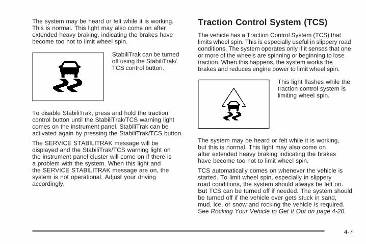
The system may be heard or felt while it is working.This is normal. This light may also come on afterextended heavy braking, indicating the brakes havebecome too hot to limit wheel spin.
StabiliTrak can be turnedoff using the StabiliTrak/TCS control button.
To disable StabiliTrak, press and hold the tractioncontrol button until the StabiliTrak/TCS warning lightcomes on the instrument panel. StabiliTrak can beactivated again by pressing the StabiliTrak/TCS button.
The SERVICE STABILITRAK message will bedisplayed and the StabiliTrak/TCS warning light onthe instrument panel cluster will come on if there isa problem with the system. When this light andthe SERVICE STABILITRAK message are on, thesystem is not operational. Adjust your drivingaccordingly.
Traction Control System (TCS)The vehicle has a Traction Control System (TCS) thatlimits wheel spin. This is especially useful in slippery roadconditions. The system operates only if it senses that oneor more of the wheels are spinning or beginning to losetraction. When this happens, the system works thebrakes and reduces engine power to limit wheel spin.
This light flashes while thetraction control system islimiting wheel spin.
The system may be heard or felt while it is working,but this is normal. This light may also come onafter extended heavy braking indicating the brakeshave become too hot to limit wheel spin.
TCS automatically comes on whenever the vehicle isstarted. To limit wheel spin, especially in slipperyroad conditions, the system should always be left on.But TCS can be turned off if needed. The system shouldbe turned off if the vehicle ever gets stuck in sand,mud, ice, or snow and rocking the vehicle is required.See Rocking Your Vehicle to Get It Out on page 4-20.
4-7

TCS can be turned off bypressing the StabiliTrak/TCS button, located next tothe gear shift lever.
When TCS is turned off, the StabiliTrak/TCS warninglight comes on the instrument panel cluster andTRACTION CONTROL OFF briefly displays.
The traction control system can be activated again bypressing the traction control button. While the tractioncontrol system is activated, the StabiliTrak/TCS warninglight comes on the instrument panel cluster andTRACTION CONTROL ON briefly displays.
If the system is limiting wheel spin when the button ispressed, the StabiliTrak/TCS warning light comes on theinstrument panel cluster. The system will not turn offuntil there is no longer a current need to limit wheel spin.Turn the system back on by pressing the buttonagain. If the light does not come on, TCS might not beworking and the vehicle should be serviced by yourdealer/retailer.
Adding non-dealer/non-retailer accessories can affectthe vehicle’s performance. See Accessories andModifications on page 5-3 for more information.
All-Wheel Drive (AWD) SystemIf the vehicle has all-wheel drive (AWD), the AWDsystem operates automatically without any actionrequired by the driver. If the front drive wheels begin toslip, the rear wheels will automatically begin to drivethe vehicle as required. Torque is also applied tothe rear wheels during launches. There may be a slightengagement noise during hard use but this is normal.
The Service All-WheelDrive Light is located onthe instrument panelcluster.
This light and the SERVICE ALL WHEEL DRIVEmessage in the DIC will come on and stay on to indicatethere may be a problem with the drive system andservice is required.
See Service All-Wheel Drive Light on page 3-39 andDIC Warnings and Messages on page 3-49 formore information.
4-8

The All-Wheel DriveDisabled Light comes onalong with the ALL WHEELDRIVE OFF messagewhen the rear drive systemis overheating.
This light will turn off when the rear drive system coolsdown. If this light stays on, it must be reset. To resetthe light, turn the ignition off and then back on again.If the light stays on, see your dealer/retailer for service.
See DIC Warnings and Messages on page 3-49 formore information.
Steering
Electric Power Steering(3.4L V6 Engine)If the engine stalls while driving, the power steeringassist system will continue to operate until you are ableto stop the vehicle. If power steering assist is lostbecause the electric power steering system is notfunctioning, the vehicle can be steered but it will takemore effort.
If you turn the steering wheel in either direction severaltimes until it stops, or hold the steering wheel in thestopped position for an extended amount of time, youmay notice a reduced amount of power steering assist.The normal amount of power steering assist should returnshortly after a few normal steering movements.
The electric power steering system does not requireregular maintenance. If you suspect steering systemproblems, such as abnormally high steering effort for aprolonged period of time, contact your dealer/retailerfor service repairs.
4-9

Hydraulic Power Steering(3.6L V6 Engine)If power steering assist is lost because the engine stopsor the power steering system is not functioning, thevehicle can be steered but it will take more effort.
Steering TipsIt is important to take curves at a reasonable speed.
Traction in a curve depends on the condition of the tiresand the road surface, the angle at which the curve isbanked, and vehicle speed. While in a curve, speedis the one factor that can be controlled.
If there is a need to reduce speed, do it before enteringthe curve, while the front wheels are straight.
Try to adjust the speed so you can drive throughthe curve. Maintain a reasonable, steady speed.Wait to accelerate until out of the curve, and thenaccelerate gently into the straightaway.
Steering in EmergenciesThere are times when steering can be more effectivethan braking. For example, you come over a hill and finda truck stopped in your lane, or a car suddenly pullsout from nowhere, or a child darts out from betweenparked cars and stops right in front of you. Theseproblems can be avoided by braking — if you canstop in time. But sometimes you cannot stop in timebecause there is no room. That is the time for evasiveaction — steering around the problem.
The vehicle can perform very well in emergencies likethese. First apply the brakes. See Braking on page 4-4.It is better to remove as much speed as possiblefrom a collision. Then steer around the problem, tothe left or right depending on the space available.
4-10

An emergency like this requires close attention anda quick decision. If holding the steering wheel at therecommended 9 and 3 o’clock positions, it can be turneda full 180 degrees very quickly without removing eitherhand. But you have to act fast, steer quickly, and just asquickly straighten the wheel once you have avoided theobject.
The fact that such emergency situations are alwayspossible is a good reason to practice defensive drivingat all times and wear safety belts properly.
Off-Road RecoveryThe vehicle’s right wheels can drop off the edge of aroad onto the shoulder while driving.
If the level of the shoulder is only slightly below thepavement, recovery should be fairly easy. Ease off theaccelerator and then, if there is nothing in the way, steerso that the vehicle straddles the edge of the pavement.Turn the steering wheel 3 to 5 inches, 8 to 13 cm, (aboutone-eighth turn) until the right front tire contacts thepavement edge. Then turn the steering wheel to gostraight down the roadway.
4-11

PassingPassing another vehicle on a two-lane road can bedangerous. To reduce the risk of danger while passing:
• Look down the road, to the sides, and to crossroadsfor situations that might affect a successful pass.If in doubt, wait.
• Watch for traffic signs, pavement markings, andlines that could indicate a turn or an intersection.Never cross a solid or double-solid line on your sideof the lane.
• Do not get too close to the vehicle you want topass. Doing so can reduce your visibility.
• Wait your turn to pass a slow vehicle.
• When you are being passed, ease to the right.
Loss of ControlLet us review what driving experts say about whathappens when the three control systems — brakes,steering, and acceleration — do not have enough frictionwhere the tires meet the road to do what the driver hasasked.
In any emergency, do not give up. Keep trying to steerand constantly seek an escape route or area of lessdanger.
SkiddingIn a skid, a driver can lose control of the vehicle.Defensive drivers avoid most skids by taking reasonablecare suited to existing conditions, and by not overdrivingthose conditions. But skids are always possible.
The three types of skids correspond to the vehicle’sthree control systems. In the braking skid, the wheelsare not rolling. In the steering or cornering skid, too muchspeed or steering in a curve causes tires to slip and losecornering force. And in the acceleration skid, too muchthrottle causes the driving wheels to spin.
Remember: Any traction control system helps avoid onlythe acceleration skid. If the traction system is off, thenan acceleration skid is best handled by easing your footoff the accelerator pedal. See Traction Control System(TCS) on page 4-7 and StabiliTrak® System onpage 4-6.
If the vehicle starts to slide, ease your foot off theaccelerator pedal and quickly steer the way you wantthe vehicle to go. If you start steering quickly enough,the vehicle may straighten out. Always be ready fora second skid if it occurs.
4-12

Of course, traction is reduced when water, snow, ice,gravel, or other material is on the road. For safety, slowdown and adjust your driving to these conditions. It isimportant to slow down on slippery surfaces becausestopping distance will be longer and vehicle control morelimited.
While driving on a surface with reduced traction,try your best to avoid sudden steering, acceleration,or braking, including reducing vehicle speed by shifting toa lower gear. Any sudden changes could cause the tiresto slide. You may not realize the surface is slippery untilthe vehicle is skidding. Learn to recognize warningclues — such as enough water, ice, or packed snow onthe road to make a mirrored surface — and slow downwhen you have any doubt.
Remember: Any Antilock Brake System (ABS) helpsavoid only the braking skid.
Driving at NightNight driving is more dangerous than day drivingbecause some drivers are likely to be impaired — byalcohol or drugs, with night vision problems, or byfatigue.
Night driving tips include:
• Drive defensively.
• Do not drink and drive.
• Reduce headlamp glare by adjusting the insiderearview mirror.
• Slow down and keep more space between you andother vehicles because headlamps can only light upso much road ahead.
• Watch for animals.
• When tired, pull off the road.
• Do not wear sunglasses.
• Avoid staring directly into approaching headlamps.
• Keep the windshield and all glass on your vehicleclean — inside and out.
• Keep your eyes moving, especially during turns orcurves.
No one can see as well at night as in the daytime.But, as we get older, these differences increase.A 50-year-old driver might need at least twice as muchlight to see the same thing at night as a 20-year-old.
4-13

Driving in Rain and on Wet RoadsRain and wet roads can reduce vehicle tractionand affect your ability to stop and accelerate. Alwaysdrive slower in these types of driving conditionsand avoid driving through large puddles anddeep-standing or flowing water.
{CAUTION:
Wet brakes can cause crashes. They might notwork as well in a quick stop and could causepulling to one side. You could lose control of thevehicle.
After driving through a large puddle of water or acar/vehicle wash, lightly apply the brake pedal untilthe brakes work normally.
Flowing or rushing water creates strong forces.Driving through flowing water could cause yourvehicle to be carried away. If this happens, youand other vehicle occupants could drown. Do notignore police warnings and be very cautious abouttrying to drive through flowing water.
HydroplaningHydroplaning is dangerous. Water can build up underyour vehicle’s tires so they actually ride on thewater. This can happen if the road is wet enough andyou are going fast enough. When your vehicle ishydroplaning, it has little or no contact with the road.
There is no hard and fast rule about hydroplaning.The best advice is to slow down when the road is wet.
Other Rainy Weather TipsBesides slowing down, other wet weather driving tipsinclude:
• Allow extra following distance.
• Pass with caution.
• Keep windshield wiping equipment in good shape.
• Keep the windshield washer fluid reservoir filled.
• Have good tires with proper tread depth. See Tireson page 5-48.
• Turn off cruise control.
4-14

Before Leaving on a Long TripTo prepare your vehicle for a long trip, consider havingit serviced by your dealer/retailer before departing.
Things to check on your own include:
• Windshield Washer Fluid: Reservoir full? Windowsclean — inside and outside?
• Wiper Blades: In good shape?
• Fuel, Engine Oil, Other Fluids: All levels checked?
• Lamps: Do they all work and are lenses clean?
• Tires: Are treads good? Are tires inflated torecommended pressure?
• Weather and Maps: Safe to travel? Haveup-to-date maps?
Highway HypnosisAlways be alert and pay attention to your surroundingswhile driving. If you become tired or sleepy, find asafe place to park your vehicle and rest.
Other driving tips include:
• Keep the vehicle well ventilated.
• Keep interior temperature cool.
• Keep your eyes moving — scan the road aheadand to the sides.
• Check the rearview mirror and vehicle instrumentsoften.
4-15

Hill and Mountain RoadsDriving on steep hills or through mountains is differentthan driving on flat or rolling terrain. Tips for drivingin these conditions include:
• Keep the vehicle serviced and in good shape.
• Check all fluid levels and brakes, tires, coolingsystem, and transmission.
• Going down steep or long hills, shift to alower gear.
{CAUTION:
If you do not shift down, the brakes could get sohot that they would not work well. You would thenhave poor braking or even none going down a hill.You could crash. Shift down to let the engineassist the brakes on a steep downhill slope.
{CAUTION:
Coasting downhill in N (Neutral) or with the ignitionoff is dangerous. The brakes will have to do all thework of slowing down and they could get so hotthat they would not work well. You would thenhave poor braking or even none going down a hill.You could crash. Always have the engine runningand the vehicle in gear when going downhill.
• Stay in your own lane. Do not swing wide or cutacross the center of the road. Drive at speedsthat let you stay in your own lane.
• Top of hills: Be alert — something could be in yourlane (stalled car, accident).
• Pay attention to special road signs (falling rocksarea, winding roads, long grades, passing orno-passing zones) and take appropriate action.
4-16

Winter Driving
Driving on Snow or IceDrive carefully when there is snow or ice between thetires and the road, creating less traction or grip. Wet icecan occur at about 32°F (0°C) when freezing rainbegins to fall, resulting in even less traction. Avoiddriving on wet ice or in freezing rain until roads canbe treated with salt or sand.
Drive with caution, whatever the condition. Accelerategently so traction is not lost. Accelerating too quicklycauses the wheels to spin and makes the surface underthe tires slick, so there is even less traction.
Try not to break the fragile traction. If you accelerate toofast, the drive wheels will spin and polish the surfaceunder the tires even more.
The Traction Control System (TCS) on page 4-7improves the ability to accelerate on slippery roads,but slow down and adjust your driving to the roadconditions. When driving through deep snow, turn offthe traction control system to help maintain vehiclemotion at lower speeds.
The Antilock Brake System (ABS) on page 4-5 improvesvehicle stability during hard stops on a slippery roads, butapply the brakes sooner than when on dry pavement.
Allow greater following distance on any slippery roadand watch for slippery spots. Icy patches can occur onotherwise clear roads in shaded areas. The surfaceof a curve or an overpass can remain icy when thesurrounding roads are clear. Avoid sudden steeringmaneuvers and braking while on ice.
Turn off cruise control, if equipped, on slippery surfaces.
4-17

Blizzard ConditionsBeing stuck in snow can be in a serious situation. Staywith the vehicle unless there is help nearby. If possible,use the Roadside Assistance Program on page 7-7.To get help and keep everyone in the vehicle safe:
• Turn on the Hazard Warning Flashers on page 3-6.
• Tie a red cloth to an outside mirror.
{CAUTION:
Snow can trap engine exhaust under the vehicle.This may cause exhaust gases to get inside.Engine exhaust contains carbon monoxide (CO)which cannot be seen or smelled. It can causeunconsciousness and even death.
If the vehicle is stuck in the snow:• Clear away snow from around the base of
your vehicle, especially any that is blockingthe exhaust pipe.
• Check again from time to time to be suresnow does not collect there.
CAUTION: (Continued)
CAUTION: (Continued)
• Open a window about two inches (5 cm) onthe side of the vehicle that is away from thewind to bring in fresh air.
• Fully open the air outlets on or under theinstrument panel.
• Adjust the Climate Control system to a settingthat circulates the air inside the vehicle andset the fan speed to the highest setting.See Climate Control System in the Index.
For more information about carbon monoxide, seeEngine Exhaust on page 2-35.
Snow can trap exhaust gases under your vehicle.This can cause deadly CO (carbon monoxide) gasto get inside. CO could overcome you and kill you.You cannot see it or smell it, so you might notknow it is in your vehicle. Clear away snow fromaround the base of your vehicle, especially anythat is blocking the exhaust.
Run the engine for short periods only as needed tokeep warm, but be careful.
To save fuel, run the engine for only short periods asneeded to warm the vehicle and then shut the engine offand close the window most of the way to save heat.
4-18

Repeat this until help arrives but only when you feelreally uncomfortable from the cold. Moving aboutto keep warm also helps.
If it takes some time for help to arrive, now and thenwhen you run the engine, push the acceleratorpedal slightly so the engine runs faster than the idlespeed. This keeps the battery charged to restartthe vehicle and to signal for help with the headlamps.Do this as little as possible to save fuel.
If Your Vehicle is Stuck in Sand,Mud, Ice, or SnowSlowly and cautiously spin the wheels to free thevehicle when stuck in sand, mud, ice, or snow.See Rocking Your Vehicle to Get It Out on page 4-20.
If the vehicle has a traction system, it can often helpto free a stuck vehicle. Refer to the vehicle’s tractionsystem in the Index. If stuck too severely for the tractionsystem to free the vehicle, turn the traction system offand use the rocking method.
{CAUTION:
If you let your vehicle’s tires spin at high speed,they can explode, and you or others could beinjured. The vehicle can overheat, causing anengine compartment fire or other damage. Spinthe wheels as little as possible and avoid goingabove 35 mph (55 km/h) as shown on thespeedometer.
For information about using tire chains on the vehicle,see Tire Chains on page 5-69.
4-19

Rocking Your Vehicle to Get It OutTurn the steering wheel left and right to clear the areaaround the front wheels. Turn off any traction or stabilitysystem. Shift back and forth between R (Reverse) and aforward gear, spinning the wheels as little as possible.To prevent transmission wear, wait until the wheels stopspinning before shifting gears. Release the acceleratorpedal while shifting, and press lightly on the acceleratorpedal when the transmission is in gear. Slowly spinningthe wheels in the forward and reverse directions causes arocking motion that could free the vehicle. If that does notget the vehicle out after a few tries, it might need to betowed out. If the vehicle does need to be towed out, seeTowing Your Vehicle on page 4-26.
Loading the VehicleIt is very important to know how much weight yourvehicle can carry. Two labels on your vehicleshow how much weight it may properly carry,the Tire and Loading Information label andthe Vehicle Certification label.
{CAUTION:
Do not load the vehicle any heavier than theGross Vehicle Weight Rating (GVWR), oreither the maximum front or rear Gross AxleWeight Rating (GAWR). If you do, parts on thevehicle can break, and it can change the wayyour vehicle handles. These could cause youto lose control and crash. Also, overloadingcan shorten the life of the vehicle.
4-20

Tire and Loading Information Label
A vehicle specific Tire and LoadingInformation label is attached to the vehicle’scenter pillar (B-pillar). With the driver’s door open,
you will find the label attached below the door lockpost (striker). The tire and loading information labellists the number of occupant seating positions(A),and the maximum vehicle capacity weight (B) inkilograms and pounds. The vehicle capacity weightincludes the weight of all occupants, cargo, and allnonfactory-installed options.
The Tire and Loading Information label also liststhe tire size of the original equipment tires (C) andthe recommended cold tire inflation pressures (D).For more information on tires and inflation, seeTires on page 5-48 and Inflation - Tire Pressureon page 5-55.
There is also important loading information on theCertification/Tire label. It tells you the Gross VehicleWeight Rating (GVWR) and the Gross Axle WeightRating (GAWR) for the front and rear axles.See “Certification/Tire Label” later in this section.
Label Example
4-21

Steps for Determining Correct Load Limit1. Locate the statement “The combined weight
of occupants and cargo should never exceedXXX kg or XXX lbs” on your vehicle’s placard.
2. Determine the combined weight of the driverand passengers that will be riding in yourvehicle.
3. Subtract the combined weight of the driverand passengers from XXX kg or XXX lbs.
4. The resulting figure equals the availableamount of cargo and luggage load capacity.For example, if the “XXX” amount equals1400 lbs and there will be five 150 lbpassengers in your vehicle, the amount ofavailable cargo and luggage load capacity is650 lbs (1400 − 750 (5 x 150) = 650 lbs).
5. Determine the combined weight of luggageand cargo being loaded on the vehicle.That weight may not safely exceed theavailable cargo and luggage load capacitycalculated in Step 4.
6. If your vehicle will be towing a trailer, the loadfrom your trailer will be transferred to yourvehicle. Consult this manual to determine howthis reduces the available cargo and luggageload capacity for your vehicle.
If your vehicle can tow a trailer, see Towing aTrailer on page 4-33 for important informationon towing a trailer, towing safety rules, andtrailering tips.
4-22

Item Description Total
AMaximum VehicleCapacity Weight forExample 1 =
1,000 lbs(453 kg)
BSubtract OccupantWeight 150 lbs(68 kg) × 2 =
300 lbs (136 kg)
C Available Occupantand Cargo Weight = 700 lbs (317 kg)
Item Description Total
AMaximum VehicleCapacity Weight forExample 2 =
1,000 lbs(453 kg)
BSubtract OccupantWeight 150 lbs(68 kg) × 5 =
750 lbs (340 kg)
C Available CargoWeight = 250 lbs (113 kg)
Example 1 Example 2
4-23

Item Description Total
AMaximum VehicleCapacity Weight forExample 3 =
1,000 lbs(453 kg)
BSubtract OccupantWeight 200 lbs(91 kg) × 5 =
1,000 lbs(453 kg)
C Available CargoWeight = 0 lbs (0 kg)
Refer to your vehicle’s tire and loading informationlabel for specific information about your vehicle’smaximum vehicle capacity weight and seatingpositions. The combined weight of the driver,passengers, and cargo should never exceed yourvehicle’s maximum vehicle capacity weight.
Certification Label
A vehicle specific Certification/Tire label is foundon the rear edge of the driver’s door, or onthe vehicle’s center pillar (B-pillar).The label shows the size of your original tires andthe inflation pressures needed to obtain the grossweight capacity of your vehicle. This is called theGross Vehicle Weight Rating (GVWR). The GVWRincludes the weight of the vehicle, all occupants,fuel, and cargo.
Example 3
4-24

The Certification/Tire label also tells you themaximum weights for the front and rear axles,called the Gross Axle Weight Rating (GAWR).To find out the actual loads on your front andrear axles, you need to go to a weigh station andweigh your vehicle. Your dealer can help youwith this. Be sure to spread out your load equallyon both sides of the centerline.
Never exceed the GVWR for your vehicle or theGAWR for either the front or rear axle.
{CAUTION:
Do not load the vehicle any heavier than theGross Vehicle Weight Rating (GVWR), oreither the maximum front or rear Gross AxleWeight Rating (GAWR). If you do, parts on thevehicle can break, and it can change the wayyour vehicle handles. These could cause youto lose control and crash. Also, overloadingcan shorten the life of the vehicle.
Notice: Overloading your vehicle may causedamage. Repairs would not be covered by yourwarranty. Do not overload your vehicle.
If you put things inside your vehicle — likesuitcases, tools, packages, or anything else — theywill go as fast as the vehicle goes. If you have tostop or turn quickly, or if there is a crash, they willkeep going.
{CAUTION:
Things you put inside your vehicle can strikeand injure people in a sudden stop or turn, orin a crash.
• Put things in the cargo area of yourvehicle. Try to spread the weight evenly.
• Never stack heavier things, likesuitcases, inside the vehicle so that someof them are above the tops of the seats.
• Do not leave an unsecured child restraintin your vehicle.
• When you carry something inside thevehicle, secure it whenever you can.
• Do not leave a seat folded down unlessyou need to.
4-25

Towing
Towing Your VehicleTo avoid damage, the disabled vehicle should be towedwith all four wheels off the ground. Consult yourdealer/retailer or a professional towing service if thedisabled vehicle must be towed. See RoadsideAssistance Program on page 7-7.
To tow the vehicle behind another vehicle forrecreational purposes, such as behind a motorhome,see “Recreational Vehicle Towing” following.
Recreational Vehicle TowingRecreational vehicle towing means towing the vehiclebehind another vehicle – such as behind a motorhome.The two most common types of recreational vehicletowing are known as dinghy towing and dolly towing.Dinghy towing is towing the vehicle with all four wheelson the ground. Dolly towing is towing the vehiclewith two wheels on the ground and two wheels upon a device known as a dolly.
Here are some important things to consider beforerecreational vehicle towing:
• What is the towing capacity of the towing vehicle?Be sure to read the tow vehicle manufacturer’srecommendations.
• What is the distance that will be travelled? Somevehicles have restrictions on how far and howlong they can tow.
• Is the proper towing equipment going to be used?See your dealer/retailer or trailering professionalfor additional advice and equipmentrecommendations.
• Is the vehicle ready to be towed? Just as preparingthe vehicle for a long trip, make sure the vehicle isprepared to be towed. See Before Leaving on aLong Trip on page 4-15.
4-26
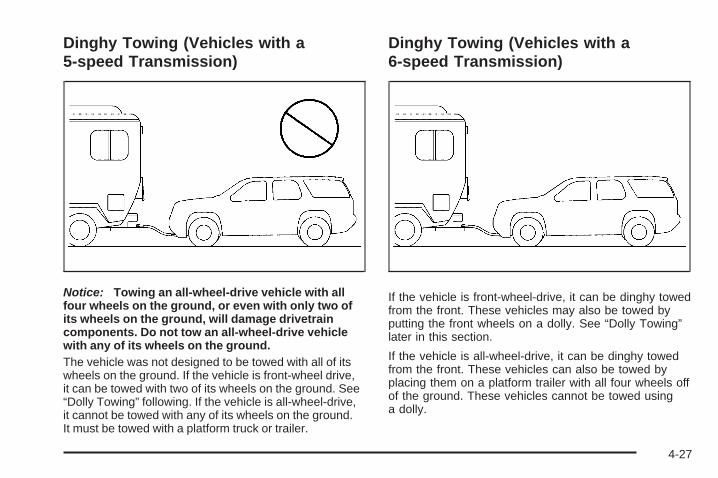
Dinghy Towing (Vehicles with a5-speed Transmission)
Notice: Towing an all-wheel-drive vehicle with allfour wheels on the ground, or even with only two ofits wheels on the ground, will damage drivetraincomponents. Do not tow an all-wheel-drive vehiclewith any of its wheels on the ground.The vehicle was not designed to be towed with all of itswheels on the ground. If the vehicle is front-wheel drive,it can be towed with two of its wheels on the ground. See“Dolly Towing” following. If the vehicle is all-wheel-drive,it cannot be towed with any of its wheels on the ground.It must be towed with a platform truck or trailer.
Dinghy Towing (Vehicles with a6-speed Transmission)
If the vehicle is front-wheel-drive, it can be dinghy towedfrom the front. These vehicles may also be towed byputting the front wheels on a dolly. See “Dolly Towing”later in this section.
If the vehicle is all-wheel-drive, it can be dinghy towedfrom the front. These vehicles can also be towed byplacing them on a platform trailer with all four wheels offof the ground. These vehicles cannot be towed usinga dolly.
4-27
For vehicles being dinghy towed, re-install the fuse andrun the vehicle at the beginning of each day and ateach RV fuel stop for about five minutes. This willensure proper lubrication of transmission components.
To tow a vehicle with a 6–speed transmission fromthe front with all four wheels on the ground:
1. Position the vehicle being towed behind the towvehicle and shift the transmission to P (Park).
2. Turn the ignition to LOCK/OFF.
3. Firmly set the parking brake.
4. Securely attach the vehicle being towed to the towvehicle.
5. Turn the ignition to ACC/ACCESSORY.
6. Shift the transmission to N (Neutral).
7. To prevent the battery from draining while thevehicle is being towed, remove the 50 ampBATT1 fuse from the engine compartment fuseblock and store in a safe location. See EngineCompartment Fuse Block on page 5-93.
8. Release the parking brake.
Notice: If the vehicle is towed without performingeach of the steps listed under “Dinghy Towing,”the automatic transmission could be damaged.Be sure to follow all steps of the dinghy towingprocedure prior to and after towing the vehicle.
Notice: If 65 mph (105 km/h) is exceeded whiletowing the vehicle, it could be damaged. Neverexceed 65 mph (105 km/h) while towing the vehicle.
Once the destination has been reached:
1. Set the parking brake.
2. Reinstall the 50 amp BATT1 fuse to the enginecompartment fuse block.
3. Shift the transmission to P (Park), turn the ignitionto LOCK/OFF and remove the key from the ignition.
4. Release the parking brake.
Notice: Do not tow a vehicle with the front drivewheels on the ground if one of the front tiresis a compact spare tire. Towing with two differenttire sizes on the front of the vehicle can causesevere damage to the transmission.
4-28

Dolly Towing (Front-Wheel-DriveVehicles with a 5-speed Transmission)
To dolly tow a front-wheel drive vehicle with a 5–speedtransmission from the front with two of its wheels onthe ground:
1. Attach the dolly to the tow vehicle following thedolly manufacturer’s instructions.
2. Drive the front wheels onto the dolly.
3. Shift the transmission to P (Park).
4. Firmly set the parking brake.
5. Clamp the steering wheel in a straight-aheadposition with a clamping device designed for towing.
6. Secure the vehicle to the dolly following themanufacturer’s instructions.
7. Release the parking brake only after the vehiclebeing towed is firmly attached to the dolly.
8. Turn the ignition to LOCK/OFF.
4-29

Dolly Towing (All-Wheel-Drive Vehicleswith a 5-speed Transmission)
Notice: Towing an all-wheel-drive vehicle with allfour wheels on the ground, or even with only two ofits wheels on the ground, will damage drivetraincomponents. Do not tow an all-wheel-drive vehiclewith any of its wheels on the ground.
If the vehicle is all-wheel-drive with a 5–speedtransmission, it cannot be towed with any of its wheelson the ground. It must be towed with a platform truckor trailer.
Dolly Towing (Front-Wheel-DriveVehicles with a 6-speed Transmission)
To tow a front-wheel-drive vehicle from the front withtwo wheels on the ground:
1. Attach the dolly to the tow vehicle following thedolly manufacturer’s instructions.
2. Drive the front wheels onto the dolly.
4-30

3. Shift the transmission to P (Park).
4. Firmly set the parking brake.
5. Clamp the steering wheel in a straight-aheadposition with a clamping device designed for towing.
6. Secure the vehicle to the dolly following themanufacturer’s instructions.
7. Release the parking brake only after the vehiclebeing towed is firmly attached to the dolly.
8. Turn the ignition to LOCK/OFF.
Dolly Towing (All-Wheel-Drive Vehicleswith a 6-speed Transmission)
All-wheel-drive vehicles must not be towed with twowheels on the ground. To properly tow these vehicles,they should be placed on a platform truck or trailer withall four wheels off of the ground or dinghy towed fromthe front.
4-31

Towing the Vehicle From the Rear
Notice: Towing the vehicle from the rear coulddamage it. Also, repairs would not be covered by thevehicle warranty. Never have the vehicle towedfrom the rear.
4-32

Towing a Trailer
{CAUTION:
The driver can lose control when pulling a trailer ifthe correct equipment is not used or the vehicle isnot driven properly. For example, if the trailer istoo heavy, the brakes may not work well — oreven at all. The driver and passengers couldbe seriously injured. The vehicle may also bedamaged; the resulting repairs would not becovered by the vehicle warranty. Pull a trailer onlyif all the steps in this section have been followed.Ask your dealer/retailer for advice and informationabout towing a trailer with the vehicle.
Notice: Pulling a trailer improperly can damagethe vehicle and result in costly repairs not coveredby the vehicle warranty. To pull a trailer correctly,follow the advice in this section and see yourdealer/retailer for important information abouttowing a trailer with the vehicle.
The vehicle can tow a trailer if it is equipped with theproper trailer towing equipment.
To identify the trailering capacity of the vehicle, readthe information in “Weight of the Trailer” that appearslater in this section.
Trailering is different than just driving the vehicle by itself.Trailering means changes in handling, acceleration,braking, durability and fuel economy. Successful, safetrailering takes correct equipment, and it has to be usedproperly.
The following information has many time-tested,important trailering tips and safety rules. Many of theseare important for your safety and that of your passengers.So please read this section carefully before pulling atrailer.
Load-pulling components such as the engine,transmission, wheel assemblies and tires are forced towork harder against the drag of the added weight.The engine is required to operate at relatively higherspeeds and under greater loads, generating extra heat.The trailer also adds considerably to wind resistance,increasing the pulling requirements.
4-33

Pulling A TrailerHere are some important points:
• There are many different laws, including speed limitrestrictions, having to do with trailering. Make surethe rig will be legal, not only where you live butalso where you will be driving. A good source forthis information can be state or provincial police.
• Consider using a sway control. See “Hitches” laterin this section.
• Do not tow a trailer at all during the first 500 miles(800 km) the new vehicle is driven. The engine,axle or other parts could be damaged.
• Then, during the first 500 miles (800 km) that atrailer is towed, do not drive over 50 mph (80 km/h)and do not make starts at full throttle. This helpsthe engine and other parts of the vehicle wear in atthe heavier loads.
• Vehicles can tow in D (Drive). Shift the transmissionto a lower gear if the transmission shifts too oftenunder heavy loads and/or hilly conditions.
• Obey speed limit restrictions when towing a trailer.Do not drive faster than the maximum postedspeed for trailers, or no more than 55 mph(90 km/h), to save wear on the vehicle’s parts.
Three important considerations have to do with weight:
• Weight of the trailer
• Weight of the trailer tongue
• Weight on your vehicle’s tires
Weight of the TrailerHow heavy can a trailer safely be?
The vehicle can tow up to 3,500 lbs (1 575 kg).But even that can be too heavy.
It depends on how the rig is used. For example, speed,altitude, road grades, outside temperature and howmuch the vehicle is used to pull a trailer are allimportant. It can depend on any special equipment onthe vehicle, and the amount of tongue weight the vehiclecan carry. See “Weight of the Trailer Tongue” later inthis section for more information.
Maximum trailer weight is calculated assuming only thedriver is in the tow vehicle and it has all the requiredtrailering equipment. The weight of additional optionalequipment, passengers and cargo in the tow vehiclemust be subtracted from the maximum trailer weight.
Ask your dealer/retailer for our trailering informationor advice, or write us at our Customer AssistanceOffices. See Customer Assistance Offices on page 7-6for more information.
4-34

Weight of the Trailer TongueThe tongue load (A) of any trailer is an important weightto measure because it affects the total gross weight of thevehicle. The Gross Vehicle Weight (GVW) includes thecurb weight of the vehicle, any cargo carried in it, and thepeople who will be riding in the vehicle. If there are a lot ofoptions, equipment, passengers or cargo in the vehicle, itwill reduce the tongue weight the vehicle can carry, whichwill also reduce the trailer weight the vehicle can tow. Iftowing a trailer, the tongue load must be added to theGVW because the vehicle will be carrying that weight,too. See Loading the Vehicle on page 4-20 for moreinformation about the vehicle’s maximum load capacity. If a weight-carrying hitch or a weight-distributing hitch
is being used, the trailer tongue (A) should weigh10-15 percent of the total loaded trailer weight (B).
After loading the trailer, weigh the trailer and then thetongue, separately, to see if the weights are proper.If they are not, adjustments might be made by movingsome items around in the trailer.
4-35

Total Weight on the Vehicle’s TiresBe sure the vehicle’s tires are inflated to the upper limitfor cold tires. These numbers can be found on theCertification label or see Loading the Vehicle onpage 4-20 for more information. Make sure not to goover the GVW limit for the vehicle, or the GAWR,including the weight of the trailer tongue.
HitchesIt is important to have the correct hitch equipment.Crosswinds, large trucks going by and rough roads area few reasons why the right hitch is needed.
• The rear bumper on the vehicle is not intendedfor hitches. Do not attach rental hitches or otherbumper-type hitches to it. Use only a frame-mountedhitch that does not attach to the bumper.
• Will any holes be made in the body of the vehiclewhen the trailer hitch is installed? If so, be sure toseal the holes when the hitch is removed. If they arenot sealed, deadly carbon monoxide (CO) from theengine’s exhaust can get into the vehicle. SeeEngine Exhaust on page 2-35. Sealing the holes willalso prevent dirt and water from entering the vehicle.
Safety ChainsAlways attach chains between the vehicle and thetrailer. Cross the safety chains under the tongue ofthe trailer to help prevent the tongue from contacting theroad if it becomes separated from the hitch. Instructionsabout safety chains may be provided by the hitchmanufacturer or by the trailer manufacturer. Follow themanufacturer’s recommendation for attaching safetychains and do not attach them to the bumper. Alwaysleave just enough slack so the rig can turn. Never allowsafety chains to drag on the ground.
Trailer BrakesA loaded trailer that weighs more than 1,000 lbs(450 kg) needs to have its own brake system that isadequate for the weight of the trailer. Be sure to readand follow the instructions for the trailer brakes sothey are installed, adjusted and maintained properly.Because the vehicle has StabiliTrak, do not try totap into the vehicle’s hydraulic brake system. If you do,both brake systems will not work well, or at all.
4-36

Driving with a Trailer
{CAUTION:
When towing a trailer, exhaust gases may collectat the rear of the vehicle and enter if the liftgate,trunk/hatch, or rear-most window is open.
Engine exhaust contains carbon monoxide (CO)which cannot be seen or smelled. It can causeunconsciousness and even death.
To maximize safety when towing a trailer:• Have the exhaust system inspected for
leaks and make necessary repairs beforestarting a trip.
• Never drive with the liftgate, trunk/hatch, orrear-most window open.
• Fully open the air outlets on or under theinstrument panel.
• Adjust the Climate Control system to a settingthat brings in only outside air and set the fanspeed to the highest setting. See ClimateControl System in the Index.
For more information about carbon monoxide, seeEngine Exhaust on page 2-35.
Towing a trailer requires a certain amount of experience.Get to know the rig before setting out for the openroad. Get acquainted with the feel of handling andbraking with the added weight of the trailer. And alwayskeep in mind that the vehicle you are driving is nowlonger and not as responsive as the vehicle is by itself.
Before starting, check all trailer hitch parts andattachments, safety chains, electrical connectors, lamps,tires and mirror adjustments. If the trailer has electricbrakes, start the vehicle and trailer moving and thenapply the trailer brake controller by hand to be sure thebrakes are working. This checks the electrical connectionat the same time.
During the trip, check occasionally to be sure that theload is secure, and that the lamps and any trailer brakesare still working.
4-37

Electronic Trailer Sway ControlElectronic Trailer Sway Control is integrated into theStabiliTrak system of the vehicle. This feature detectsthe occurrence of trailer sway that may be caused byimproper trailer weight balance, or excessive vehiclespeed. When the system detects trailer sway, theStabiliTrak system may begin to apply the front brakes,without you pressing the brake pedal, to help in stabilizingthe vehicle. The StabiliTrak warning light will flash toindicate that vehicle speed should be reduced. If thetrailer continues to sway, StabiliTrak will reduce enginetorque as a method to reduce the speed of the vehicle.Reducing the speed of the vehicle is necessary toreduce trailer sway. Electronic Trailer Sway Controlis de-activated when StabiliTrak is turned off, and isre-activated when it is turned back on. See StabiliTrak®
System on page 4-6.
Following DistanceStay at least twice as far behind the vehicle ahead asyou would when driving the vehicle without a trailer.This can help to avoid situations that require heavybraking and sudden turns.
PassingMore passing distance is needed when towing a trailer.Because the rig is longer, it is necessary to go muchfarther beyond the passed vehicle before returning tothe lane.
Backing UpHold the bottom of the steering wheel with one hand.Then, to move the trailer to the left, move that handto the left. To move the trailer to the right, move yourhand to the right. Always back up slowly and, if possible,have someone guide you.
4-38

Making Turns
Notice: Making very sharp turns while traileringcould cause the trailer to come in contact with thevehicle. The vehicle could be damaged. Avoidmaking very sharp turns while trailering.
When turning with a trailer, make wider turns thannormal. Do this so the trailer will not strike softshoulders, curbs, road signs, trees or other objects.Avoid jerky or sudden maneuvers. Signal well inadvance.
Turn Signals When Towing a TrailerThe arrows on the instrument panel flash wheneversignaling a turn or lane change. Properly hooked up, thetrailer lamps also flash, telling other drivers the vehicleis turning, changing lanes or stopping.
When towing a trailer, the arrows on the instrumentpanel flash for turns even if the bulbs on the trailerare burned out. For this reason you may think otherdrivers are seeing the signal when they are not.It is important to check occasionally to be sure thetrailer bulbs are still working.
Driving On GradesReduce speed and shift to a lower gear before startingdown a long or steep downgrade. If the transmission isnot shifted down, the brakes might have to be used somuch that they would get hot and no longer work well.
On a long uphill grade, shift down and reduce thevehicle’s speed to around 45 mph (70 km/h) to reducethe possibility of the engine and the transmissionoverheating.
Vehicles can tow in D (Drive). Shift the transmission toa lower gear if the transmission shifts too often underheavy loads and/or hilly conditions.
When towing at high altitude on steep uphill grades,consider the following: Engine coolant will boil at a lowertemperature than at normal altitudes. If the engine isturned off immediately after towing at high altitude onsteep uphill grades, the vehicle may show signs similar toengine overheating. To avoid this, let the engine run whileparked, preferably on level ground, with the automatictransmission in P (Park) for a few minutes before turningthe engine off. If the overheat warning comes on, seeEngine Overheating on page 5-28.
4-39

Parking on Hills
{CAUTION:
Parking the vehicle on a hill with the trailerattached can be dangerous. If something goeswrong, the rig could start to move. People can beinjured, and both the vehicle and the trailer can bedamaged. When possible, always park the rig on aflat surface.
If parking the rig on a hill:
1. Press the brake pedal, but do not shift into P (Park)yet. Turn the wheels into the curb if facing downhillor into traffic if facing uphill.
2. Have someone place chocks under the trailerwheels.
3. When the wheel chocks are in place, release theregular brakes until the chocks absorb the load.
4. Reapply the brake pedal. Then apply the parkingbrake and shift into P (Park).
5. Release the brake pedal.
Leaving After Parking on a Hill1. Apply and hold the brake pedal while you:
• Start the engine
• Shift into a gear
• Release the parking brake
2. Let up on the brake pedal.
3. Drive slowly until the trailer is clear of the chocks.
4. Stop and have someone pick up and store thechocks.
Maintenance When Trailer TowingThe vehicle needs service more often when pulling atrailer. See this manual’s Maintenance Scheduleor Index for more information. Things that are especiallyimportant in trailer operation are automatic transmissionfluid, engine oil, axle lubricant, belts, cooling systemand brake system. It is a good idea to inspectthese before and during the trip.Check periodically to see that all hitch nuts and boltsare tight.
Engine Cooling When Trailer TowingThe cooling system may temporarily overheat duringsevere operating conditions. See Engine Overheating onpage 5-28.
4-40

Service ............................................................5-3Accessories and Modifications ..........................5-3California Proposition 65 Warning .....................5-4California Perchlorate Materials Requirements .....5-4Doing Your Own Service Work .........................5-4Adding Equipment to the Outside of the
Vehicle ......................................................5-5Fuel ................................................................5-5
Gasoline Octane ............................................5-5Gasoline Specifications ....................................5-6California Fuel ...............................................5-6Additives .......................................................5-6Fuels in Foreign Countries ...............................5-7Filling the Tank ..............................................5-8Filling a Portable Fuel Container .....................5-10
Checking Things Under the Hood ....................5-10Hood Release ..............................................5-11Engine Compartment Overview .......................5-12Engine Oil ...................................................5-15Engine Oil Life System ..................................5-18Engine Air Cleaner/Filter ................................5-20Automatic Transmission Fluid .........................5-22Cooling System ............................................5-22Engine Coolant .............................................5-23Engine Overheating .......................................5-28
Overheated Engine ProtectionOperating Mode ........................................5-29
Power Steering Fluid .....................................5-30Windshield Washer Fluid ................................5-31Brakes ........................................................5-32Battery ........................................................5-35Jump Starting ...............................................5-36
All-Wheel Drive ..............................................5-41Headlamp Aiming ...........................................5-43Bulb Replacement ..........................................5-43
Halogen Bulbs ..............................................5-43Headlamps, Front Turn Signal, Sidemarker,
and Parking Lamps ....................................5-44Taillamps, Turn Signal, Stoplamps and
Back-up Lamps .........................................5-45License Plate Lamp ......................................5-46Replacement Bulbs .......................................5-46
Windshield Wiper Blade Replacement ..............5-47Tires ..............................................................5-48
Tire Sidewall Labeling ...................................5-49Tire Terminology and Definitions .....................5-52Inflation - Tire Pressure .................................5-55High-Speed Operation ...................................5-56Tire Pressure Monitor System .........................5-57
Section 5 Service and Appearance Care
5-1

Tire Pressure Monitor Operation .....................5-59Tire Inspection and Rotation ...........................5-62When It Is Time for New Tires .......................5-63Buying New Tires .........................................5-64Different Size Tires and Wheels ......................5-66Uniform Tire Quality Grading ..........................5-66Wheel Alignment and Tire Balance ..................5-68Wheel Replacement ......................................5-68Tire Chains ..................................................5-69If a Tire Goes Flat ........................................5-70Changing a Flat Tire .....................................5-70Removing the Spare Tire and Tools ................5-72Removing the Flat Tire and Installing the
Spare Tire ................................................5-73Storing a Flat or Spare Tire and Tools ............5-79Compact Spare Tire ......................................5-81
Appearance Care ............................................5-82Interior Cleaning ...........................................5-82Fabric/Carpet ...............................................5-83Leather .......................................................5-84Instrument Panel, Vinyl, and Other
Plastic Surfaces ........................................5-85Care of Safety Belts ......................................5-85
Weatherstrips ...............................................5-85Washing Your Vehicle ...................................5-86Cleaning Exterior Lamps/Lenses .....................5-86Finish Care ..................................................5-87Windshield and Wiper Blades .........................5-87Aluminum or Chrome-Plated Wheels
and Trim ..................................................5-88Tires ...........................................................5-88Sheet Metal Damage .....................................5-89Finish Damage .............................................5-89Underbody Maintenance ................................5-89Chemical Paint Spotting .................................5-89
Vehicle Identification ......................................5-90Vehicle Identification Number (VIN) .................5-90Service Parts Identification Label .....................5-90
Electrical System ............................................5-91Add-On Electrical Equipment ..........................5-91Windshield Wiper Fuses ................................5-91Fuses and Circuit Breakers ............................5-91Instrument Panel Fuse Block ..........................5-92Engine Compartment Fuse Block ....................5-93
Capacities and Specifications ..........................5-97
Section 5 Service and Appearance Care
5-2

ServiceFor service and parts needs, visit your dealer/retailer.You will receive genuine GM parts and GM-trained andsupported service people.
Genuine GM parts have one of these marks:
Accessories and ModificationsWhen non-dealer/non-retailer accessories are addedto the vehicle, they can affect vehicle performance andsafety, including such things as airbags, braking, stability,ride and handling, emissions systems, aerodynamics,durability, and electronic systems like antilock brakes,traction control, and stability control. Some of theseaccessories could even cause malfunction or damagenot covered by the vehicle warranty.
Damage to vehicle components resulting from theinstallation or use of non-GM certified parts, includingcontrol module modifications, are not covered under theterms of the vehicle warranty and may affect remainingwarranty coverage for affected parts.
GM Accessories are designed to complement andfunction with other systems on the vehicle. Your GMdealer/retailer can accessorize the vehicle using genuineGM Accessories. When you go to your GM dealer/retailer and ask for GM Accessories, you will knowthat GM-trained and supported service technicianswill perform the work using genuine GM Accessories.
Also, see Adding Equipment to Your Airbag-EquippedVehicle on page 1-68.
5-3

California Proposition 65 WarningMost motor vehicles, including this one, contain and/oremit chemicals known to the State of California to causecancer and birth defects or other reproductive harm.Engine exhaust, many parts and systems (includingsome inside the vehicle), many fluids, and somecomponent wear by-products contain and/or emitthese chemicals.
California Perchlorate MaterialsRequirementsCertain types of automotive applications, such asairbag initiators, seat belt pretensioners, and lithiumbatteries contained in remote keyless transmitters,may contain perchlorate materials. Special handlingmay be necessary. For additional information, seewww.dtsc.ca.gov/hazardouswaste/perchlorate.
Doing Your Own Service Work
{CAUTION:
You can be injured and the vehicle could bedamaged if you try to do service work on avehicle without knowing enough about it.
• Be sure you have sufficient knowledge,experience, the proper replacement parts,and tools before attempting any vehiclemaintenance task.
• Be sure to use the proper nuts, bolts, andother fasteners. English and metric fastenerscan be easily confused. If the wrong fastenersare used, parts can later break or fall off.You could be hurt.
If doing some of your own service work, use the properservice manual. It tells you much more about how toservice the vehicle than this manual can. To order theproper service manual, see Service Publications OrderingInformation on page 7-16.
This vehicle has an airbag system. Before attemptingto do your own service work, see Servicing YourAirbag-Equipped Vehicle on page 1-68.
5-4
Keep a record with all parts receipts and list themileage and the date of any service work performed.See Maintenance Record on page 6-17.
Adding Equipment to the Outside ofthe VehicleThings added to the outside of the vehicle can affect theairflow around it. This can cause wind noise and canaffect fuel economy and windshield washer performance.Check with your dealer/retailer before adding equipmentto the outside of the vehicle.
FuelUse of the recommended fuel is an important part ofthe proper maintenance of this vehicle. To help keep theengine clean and maintain optimum vehicle performance,we recommend the use of gasoline advertised asTOP TIER Detergent Gasoline.
The 8th digit of the Vehicle Identification Number (VIN)shows the code letter or number that identifies thevehicle’s engine. The VIN is at the top left of theinstrument panel. See Vehicle IdentificationNumber (VIN) on page 5-90.
Gasoline OctaneIf the vehicle has the 3.4L V6 engine (VIN Code F), useregular unleaded gasoline with a posted octane ratingof 87 or higher. If the octane rating is less than 87,you might notice an audible knocking noise when youdrive, commonly referred to as spark knock. If thisoccurs, use a gasoline rated at 87 octane or higheras soon as possible. If you are using gasoline ratedat 87 octane or higher and you hear heavy knocking,the engine needs service.
If the vehicle has the 3.6L V6 engine (VIN Code 7),use regular unleaded gasoline with a posted octanerating of 87 or higher. For best performance or trailertowing, you could choose to use middle grade 89 octaneunleaded gasoline. If the octane rating is less than 87,you might notice an audible knocking noise when youdrive, commonly referred to as spark knock. If this occurs,use a gasoline rated at 87 octane or higher as soon aspossible. If you are using gasoline rated at 87 octane orhigher and you hear heavy knocking, the engine needsservice.
5-5

Gasoline SpecificationsAt a minimum, gasoline should meet ASTM specificationD 4814 in the United States or CAN/CGSB-3.5 or 3.511 inCanada. Some gasolines contain an octane-enhancingadditive called methylcyclopentadienyl manganesetricarbonyl (MMT). We recommend against the use ofgasolines containing MMT. See Additives on page 5-6for additional information.
California FuelIf the vehicle is certified to meet California EmissionsStandards, it is designed to operate on fuels that meetCalifornia specifications. See the underhood emissioncontrol label. If this fuel is not available in states adoptingCalifornia emissions standards, the vehicle will operatesatisfactorily on fuels meeting federal specifications, butemission control system performance might be affected.The malfunction indicator lamp could turn on and thevehicle might fail a smog-check test. See MalfunctionIndicator Lamp on page 3-34. If this occurs, return to yourauthorized dealer/retailer for diagnosis. If it is determinedthat the condition is caused by the type of fuel used,repairs might not be covered by the vehicle warranty.
AdditivesTo provide cleaner air, all gasolines in the United Statesare now required to contain additives that help preventengine and fuel system deposits from forming, allowingthe emission control system to work properly. In mostcases, you should not have to add anything to the fuel.However, some gasolines contain only the minimumamount of additive required to meet U.S. EnvironmentalProtection Agency regulations. To help keep fuel injectorsand intake valves clean, or if the vehicle experiencesproblems due to dirty injectors or valves, look for gasolinethat is advertised as TOP TIER Detergent Gasoline.
For customers who do not use TOP TIER DetergentGasoline regularly, one bottle of GM Fuel SystemTreatment PLUS, added to the fuel tank at every engineoil change, can help clean deposits from fuel injectorsand intake valves. GM Fuel System Treatment PLUSis the only gasoline additive recommended by GeneralMotors.
5-6

Also, your dealer/retailer has additives that will helpcorrect and prevent most deposit-related problems.
Gasolines containing oxygenates, such as ethers andethanol, and reformulated gasolines might be available inyour area. We recommend that you use these gasolines,if they comply with the specifications described earlier.However, E85 (85% ethanol) and other fuels containingmore than 10% ethanol must not be used in vehicles thatwere not designed for those fuels.
Notice: This vehicle was not designed for fuelthat contains methanol. Do not use fuel containingmethanol. It can corrode metal parts in the fuelsystem and also damage plastic and rubber parts.That damage would not be covered under the vehiclewarranty.
Some gasolines that are not reformulated for lowemissions can contain an octane-enhancing additivecalled methylcyclopentadienyl manganese tricarbonyl(MMT); ask the attendant where you buy gasoline
whether the fuel contains MMT. We recommend againstthe use of such gasolines. Fuels containing MMT canreduce the life of spark plugs and the performanceof the emission control system could be affected.The malfunction indicator lamp might turn on. If thisoccurs, return to your dealer/retailer for service.
Fuels in Foreign CountriesIf you plan on driving in another country outside theUnited States or Canada, the proper fuel might be hardto find. Never use leaded gasoline or any other fuel notrecommended in the previous text on fuel. Costly repairscaused by use of improper fuel would not be covered bythe vehicle warranty.
To check the fuel availability, ask an auto club, orcontact a major oil company that does business in thecountry where you will be driving.
5-7

Filling the Tank
{CAUTION:
Fuel vapor burns violently and a fuel fire cancause bad injuries. To help avoid injuries to youand others, read and follow all the instructions onthe pump island. Turn off the engine when you arerefueling. Do not smoke if you are near fuel orrefueling the vehicle. Do not use cellular phones.Keep sparks, flames, and smoking materials awayfrom fuel. Do not leave the fuel pump unattendedwhen refueling the vehicle. This is against the lawin some places. Do not re-enter the vehicle whilepumping fuel. Keep children away from the fuelpump; never let children pump fuel.
The tethered fuel cap is located behind a hinged fueldoor on the passenger side of the vehicle.
To remove the fuel cap, turn it slowly counterclockwise.The fuel cap has a spring in it; if the cap is releasedtoo soon, it will spring back to the right.
5-8

{CAUTION:
Fuel can spray out on you if you open the fuel captoo quickly. If you spill fuel and then somethingignites it, you could be badly burned. This spraycan happen if the tank is nearly full, and is morelikely in hot weather. Open the fuel cap slowly andwait for any hiss noise to stop. Then unscrew thecap all the way.
Be careful not to spill fuel. Do not top off or overfill thetank and wait a few seconds after you have finishedpumping before removing the nozzle. Clean fuel frompainted surfaces as soon as possible. See WashingYour Vehicle on page 5-86.
When replacing the fuel cap, turn it clockwise until itclicks. Make sure the cap is fully installed. The diagnosticsystem can determine if the fuel cap has been left off orimproperly installed. This would allow fuel to evaporateinto the atmosphere. See Malfunction Indicator Lampon page 3-34.
{CAUTION:
If a fire starts while you are refueling, do notremove the nozzle. Shut off the flow of fuel byshutting off the pump or by notifying the stationattendant. Leave the area immediately.
Notice: If you need a new fuel cap, be sure to getthe right type. Your dealer/retailer can get onefor you. If you get the wrong type, it may not fitproperly. This may cause the malfunction indicatorlamp to light and may damage the fuel tank andemissions system. See Malfunction Indicator Lampon page 3-34.
5-9

Filling a Portable Fuel Container
{CAUTION:
Never fill a portable fuel container while it is inthe vehicle. Static electricity discharge from thecontainer can ignite the fuel vapor. You can bebadly burned and the vehicle damaged if thisoccurs. To help avoid injury to you and others:
• Dispense fuel only into approved containers.• Do not fill a container while it is inside a
vehicle, in a vehicle’s trunk, pickup bed,or on any surface other than the ground.
• Bring the fill nozzle in contact with the insideof the fill opening before operating the nozzle.Contact should be maintained until the fillingis complete.
• Do not smoke while pumping fuel.• Do not use a cellular phone while
pumping fuel.
Checking Things Underthe Hood
{CAUTION:
An electric fan under the hood can start up andinjure you even when the engine is not running.Keep hands, clothing, and tools away from anyunderhood electric fan.
{CAUTION:
Things that burn can get on hot engine parts andstart a fire. These include liquids like fuel, oil,coolant, brake fluid, windshield washer and otherfluids, and plastic or rubber. You or others couldbe burned. Be careful not to drop or spill thingsthat will burn onto a hot engine.
5-10

Hood ReleaseTo open the hood, do the following:
1. Pull the handle withthis symbol on it. It islocated inside thevehicle, to the left ofthe brake pedal.
2. Then go to the front of the vehicle and move thesecondary hood release lever to the right.
3. Lift the hood.
Before closing the hood, be sure all the filler caps areon properly. Then pull the hood down and close it firmly.
5-11

Engine Compartment OverviewWhen you open the hood on the 3.4L V6, here is what you will see:
5-12
A. Engine Air Cleaner/Filter. See Engine AirCleaner/Filter on page 5-20.
B. Engine Oil Fill Cap. See “When to Add Engine Oil”under Engine Oil on page 5-15.
C. Engine Oil Dipstick. See “Checking Engine Oil”under Engine Oil on page 5-15.
D. Brake Fluid Reservoir. See Brakes on page 5-32.E. Engine Compartment Fuse Block. See Fuses
and Circuit Breakers on page 5-91.
F. Remote Positive (+) Terminal. See Jump Starting onpage 5-36.
G. Engine Coolant Surge Tank. See Engine Coolant onpage 5-23.
H. Windshield Washer Fluid Reservoir. See WindshieldWasher Fluid on page 5-31.
5-13

When you open the hood on the 3.6L V6, here is what you will see:
5-14

A. Engine Air Cleaner/Filter. See Engine AirCleaner/Filter on page 5-20.
B. Power Steering Fluid Reservoir (Out of View).See Power Steering Fluid on page 5-30.
C. Engine Oil Fill Cap (Out of View). See “When to AddEngine Oil” under Engine Oil on page 5-15.
D. Engine Oil Dipstick. See “Checking Engine Oil”under Engine Oil on page 5-15.
E. Brake Fluid Reservoir. See “Brake Fluid” underBrakes on page 5-32.
F. Underhood Fuse Block. See Engine CompartmentFuse Block on page 5-93.
G. Remote Positive (+) Terminal. See Jump Starting onpage 5-36.
H. Engine Coolant Recovery Tank. See Cooling Systemon page 5-22.
I. Windshield Washer Fluid Reservoir. See “AddingWasher Fluid” under Windshield Washer Fluidon page 5-31.
Engine Oil
Checking Engine OilIt is a good idea to check the engine oil level at eachfuel fill. In order to get an accurate reading, the oil mustbe warm and the vehicle must be on level ground.
The engine oil dipstick handle is a yellow loop.See Engine Compartment Overview on page 5-12for the location of the engine oil dipstick.
1. Turn off the engine and give the oil several minutesto drain back into the oil pan. If this is not done,the oil dipstick might not show the actual level.
2. Pull out the dipstick and clean it with a paper towelor cloth, then push it back in all the way. Remove itagain, keeping the tip down, and check the level.
5-15

When to Add Engine Oil
If the oil is below the cross-hatched area at thetip of the dipstick, add at least one quart/liter of therecommended oil. This section explains what kindof oil to use. For engine oil crankcase capacity,see Capacities and Specifications on page 5-97.
Notice: Do not add too much oil. If the enginehas so much oil that the oil level gets above thecross-hatched area that shows the proper operatingrange, the engine could be damaged.
See Engine CompartmentOverview on page 5-12for the location of theengine oil fill cap.
Add enough oil to put the level somewhere in the properoperating range in the cross-hatched area. Push thedipstick all the way back in when through.
SAE 5W-30 may notappear on all caps.
5-16

What Kind of Engine Oil to UseLook for three things:
• GM6094M
Use only an oil that meets GM Standard GM6094M.
• SAE 5W-30
SAE 5W-30 is best for the vehicle. These numberson an oil container show its viscosity, or thickness.Do not use other viscosity oils such as SAE 20W-50.
• American Petroleum Institute (API) starburst symbol
Oils meeting theserequirements should havethe starburst symbol onthe container. This symbolindicates that the oil hasbeen certified by theAmerican PetroleumInstitute (API).
Notice: Use only engine oil identified as meetingGM Standard GM6094M and showing the AmericanPetroleum Institute Certified For Gasoline Enginesstarburst symbol. Failure to use the recommendedoil can result in engine damage not covered bythe vehicle warranty.
Cold Temperature OperationIf in an area of extreme cold, where the temperaturefalls below −20°F (−29°C), use either an SAE 5W-30synthetic oil or an SAE 0W-30 engine oil. Both provideeasier cold starting for the engine at extremely lowtemperatures. Always use an oil that meets the requiredspecification, GM6094M. See “What Kind of Engine Oilto Use” for more information.
5-17

Engine Oil Additives / Engine OilFlushesDo not add anything to the oil. The recommendedoils with the starburst symbol that meet GM StandardGM6094M are all that is needed for good performanceand engine protection.
Engine oil system flushes are not recommended andcould cause engine damage not covered by the vehiclewarranty.
Engine Oil Life System
When to Change Engine OilThis vehicle has a computer system that indicates whento change the engine oil and filter. This is based onengine revolutions and engine temperature, and not onmileage. Based on driving conditions, the mileage atwhich an oil change is indicated can vary considerably.For the oil life system to work properly, the systemmust be reset every time the oil is changed.
When the system has calculated that oil life has beendiminished, it indicates that an oil change is necessary.A change engine oil light and a CHANGE ENGINE OILSOON message come on. Change the oil as soon aspossible within the next 600 miles (1 000 km). It ispossible that, if driving under the best conditions, theoil life system might not indicate that an oil change isnecessary for over a year. However, the engine oil andfilter must be changed at least once a year and at thistime the system must be reset. Your dealer/retailer hastrained service people who will perform this work usinggenuine parts and reset the system. It is also importantto check the oil regularly and keep it at the proper level.
If the system is ever reset accidentally, the oil must bechanged at 3,000 miles (5 000 km) since the last oilchange. Remember to reset the oil life system wheneverthe oil is changed.
5-18

How to Reset the Engine Oil LifeSystemThe Engine Oil Life System calculates when to changethe engine oil and filter based on vehicle use. Wheneverthe oil is changed, reset the system so it can calculatewhen the next oil change is required. If a situation occurswhere the oil is changed prior to a change engine oil lightor CHANGE ENGINE OIL SOON message being turnedon, reset the system.
1. Turn the ignition key to ON/RUN with theengine off.
2. Fully press and release the accelerator pedalthree times within five seconds.The change engine oil light will flash while thesystem is resetting.
3. When the light stops flashing, turn the key toLOCK/OFF.
If the light or message comes back on and stays onwhen the vehicle is started, the engine oil life systemhas not reset. Repeat the procedure.
What to Do with Used OilUsed engine oil contains certain elements that can beunhealthy for your skin and could even cause cancer.Do not let used oil stay on your skin for very long. Cleanyour skin and nails with soap and water, or a good handcleaner. Wash or properly dispose of clothing or ragscontaining used engine oil. See the manufacturer’swarnings about the use and disposal of oil products.
Used oil can be a threat to the environment. If youchange your own oil, be sure to drain all the oil fromthe filter before disposal. Never dispose of oil by puttingit in the trash, pouring it on the ground, into sewers,or into streams or bodies of water. Recycle it by takingit to a place that collects used oil.
5-19

Engine Air Cleaner/FilterThe engine air cleaner/filter is located in the enginecompartment on the passenger’s side of the vehicle.See Engine Compartment Overview on page 5-12for more information on location.
When to Inspect the Engine AirCleaner/FilterInspect the air cleaner/filter at the Maintenance IIintervals and replace it at the first oil change aftereach 50,000 mile (80 000 km) interval. See ScheduledMaintenance on page 6-4 for more information.If you are driving in dusty/dirty conditions, inspectthe filter at each engine oil change.
How to Inspect the Engine AirCleaner/FilterTo inspect the air cleaner/filter remove the filter fromthe vehicle and lightly shake the filter to release loosedust and dirt. If the filter remains caked with dirt, a newfilter is required.
To inspect or replace the engine air cleaner/filter, do thefollowing:
1. Turn off the engine.
2. Disconnect the air flow sensor electrical connector.
3. Loosen the screws on the clamps holding the airoutlet duct in place. Do not pry the clamps off.
5-20

4. Remove the air outlet duct.
5. Undo the clamps on the filter cover. To removethe cover, pull up on the front and then pull thecover out.
6. Inspect or replace the engine air cleaner/filter.Wipe all dust from inside of the housing andinspect the air cleaner and air outlet duct for cracks,cuts, and deterioration. The air outlet duct mustbe replaced if damaged.
7. Reinstall the filter cover and latch the clamps.
8. Reattach the air outlet duct and tighten the screwson the clamps that hold the duct in place.
9. Reconnect the air flow sensor electrical connector.
{CAUTION:
Operating the engine with the air cleaner/filteroff can cause you or others to be burned. The aircleaner not only cleans the air; it helps to stopflames if the engine backfires. If it is not thereand the engine backfires, you could be burned.Do not drive with it off, and be careful working onthe engine with the air cleaner/filter off.
Notice: If the air cleaner/filter is off, a backfire cancause a damaging engine fire. And, dirt can easily getinto the engine, which will damage it. Always havethe air cleaner/filter in place when you are driving.
5-21
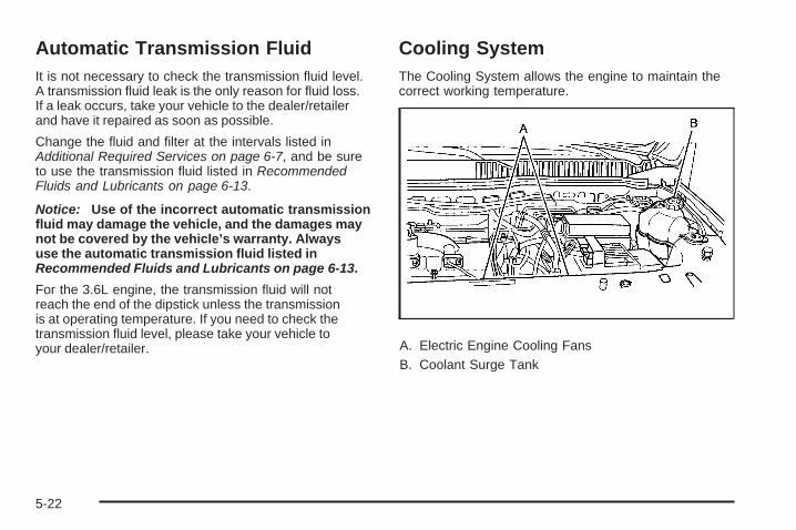
Automatic Transmission FluidIt is not necessary to check the transmission fluid level.A transmission fluid leak is the only reason for fluid loss.If a leak occurs, take your vehicle to the dealer/retailerand have it repaired as soon as possible.
Change the fluid and filter at the intervals listed inAdditional Required Services on page 6-7, and be sureto use the transmission fluid listed in RecommendedFluids and Lubricants on page 6-13.
Notice: Use of the incorrect automatic transmissionfluid may damage the vehicle, and the damages maynot be covered by the vehicle’s warranty. Alwaysuse the automatic transmission fluid listed inRecommended Fluids and Lubricants on page 6-13.
For the 3.6L engine, the transmission fluid will notreach the end of the dipstick unless the transmissionis at operating temperature. If you need to check thetransmission fluid level, please take your vehicle toyour dealer/retailer.
Cooling SystemThe Cooling System allows the engine to maintain thecorrect working temperature.
A. Electric Engine Cooling FansB. Coolant Surge Tank
5-22

{CAUTION:
An electric engine cooling fan under the hood canstart up even when the engine is not running andcan cause injury. Keep hands, clothing, and toolsaway from any underhood electric fan.
{CAUTION:
Heater and radiator hoses, and other engine parts,can be very hot. Do not touch them. If you do, youcan be burned.
Do not run the engine if there is a leak. If you runthe engine, it could lose all coolant. That couldcause an engine fire, and you could be burned.Get any leak fixed before you drive the vehicle.
Notice: Using coolant other than DEX-COOL® cancause premature engine, heater core, or radiatorcorrosion. In addition, the engine coolant couldrequire changing sooner, at 30,000 miles (50 000 km)or 24 months, whichever occurs first. Any repairswould not be covered by the vehicle warranty.Always use DEX-COOL® (silicate-free) coolant inthe vehicle.
Engine CoolantThe cooling system in the vehicle is filled withDEX-COOL® engine coolant. This coolant is designedto remain in the vehicle for five years or 150,000 miles(240 000 km), whichever occurs first.
The following explains the cooling system and how tocheck and add coolant when it is low. If there is a problemwith engine overheating, see Engine Overheating onpage 5-28
5-23

What to Use
{CAUTION:
Adding only plain water to the cooling system canbe dangerous. Plain water, or some other liquidsuch as alcohol, can boil before the proper coolantmixture will. The vehicle’s coolant warning systemis set for the proper coolant mixture. With plainwater or the wrong mixture, the engine could gettoo hot but you would not get the overheatwarning. The engine could catch fire and you orothers could be burned. Use a 50/50 mixture ofclean, drinkable water and DEX-COOL® coolant.
Use a 50/50 mixture of clean, drinkable water andDEX-COOL® coolant. If using this mixture, nothingelse needs to be added. This mixture:
• Gives freezing protection down to −34°F (−37°C),outside temperature.
• Gives boiling protection up to 265°F (129°C),engine temperature.
• Protects against rust and corrosion.
• Will not damage aluminum parts.
• Helps keep the proper engine temperature.
Notice: If an improper coolant mixture is used,the engine could overheat and be badly damaged.The repair cost would not be covered by the vehiclewarranty. Too much water in the mixture can freezeand crack the engine, radiator, heater core, andother parts.
Notice: If extra inhibitors and/or additives are usedin the vehicle’s cooling system, the vehicle couldbe damaged. Use only the proper mixture ofthe engine coolant listed in this manual for thecooling system. See Recommended Fluids andLubricants on page 6-13 for more information.
5-24

Checking CoolantThe vehicle must be on a level surface when checkingthe coolant level.
Check to see if coolant is visible in the coolant surgetank. If the coolant inside the coolant surge tank isboiling, do not do anything else until it cools down.If coolant is visible but the coolant level is not ator above the COLD FILL mark, add a 50/50 mixtureof clean, drinkable water and DEX-COOL® coolantat the coolant surge tank, but be sure the coolingsystem is cool before this is done.
The surge tank is located on the driver’s side of theengine compartment. See Engine CompartmentOverview on page 5-12 for more information on location.
When your engine is cold, the coolant level should be atthe COLD FILL line. When your engine is warm, the levelshould be at the COLD FILL line or a little higher.
The coolant level should be at the COLD FILL line. If itis not, you may have a leak in the cooling system.
How to Add Coolant to the Surge Tank
{CAUTION:
You can be burned if you spill coolant on hotengine parts. Coolant contains ethylene glycoland it will burn if the engine parts are hot enough.Do not spill coolant on a hot engine.
Notice: This vehicle has a specific coolant fillprocedure. Failure to follow this procedure couldcause the engine to overheat and be severelydamaged.
{CAUTION:
An electric engine cooling fan under the hood canstart up even when the engine is not running andcan cause injury. Keep hands, clothing, and toolsaway from any underhood electric fan.
5-25

{CAUTION:
Steam and scalding liquids from a hot coolingsystem can blow out and burn you badly. They areunder pressure, and if you turn the coolant surgetank pressure cap — even a little — they cancome out at high speed. Never turn the cap whenthe cooling system, including the coolant surgetank pressure cap, is hot. Wait for the coolingsystem and coolant surge tank pressure cap tocool if you ever have to turn the pressure cap.
If coolant is needed, add the proper DEX-COOL®
coolant mixture at the coolant surge tank.
1. You can remove thecoolant surge tankpressure cap whenthe cooling system,including the coolantsurge tank pressurecap and upper radiatorhose, is no longer hot.
Turn the pressure cap slowly counterclockwiseabout one-quarter of a turn. If you hear a hiss,wait for that to stop. This will allow any pressurestill left to be vented out the discharge hose.
2. Then keep turning the pressure cap slowly, andremove it.
3. Fill the coolant surge tank with the properDEX-COOL® coolant mixture, to the COLD FILL line.
5-26

4. With the coolant surge tank pressure cap off, startthe engine and let it run until you can feel the upperradiator hose getting hot. Watch out for the enginecooling fans.By this time, the coolant level inside the coolantsurge tank may be lower. If the level is lower, addmore of the proper DEX-COOL® coolant mixtureto the coolant surge tank until the level reachesthe COLD FILL line.
5. Then replace the pressure cap. Be sure thepressure cap is hand-tight.
6. After driving the vehicle, check the level in thesurge tank again when the cooling system hascooled down.
If the coolant is not at the proper level, repeat Steps 1through 3 and reinstall the pressure cap. If the coolantis not at the proper level when the system coolsdown again, see your dealer/retailer.
Notice: If the pressure cap is not tightly installed,coolant loss and possible engine damage mayoccur. Be sure the cap is properly and tightlysecured.
5-27

Engine OverheatingThe vehicle has several indicators to warn of engineoverheating.
You will find a coolant temperature gage on yourvehicle’s instrument panel. See Engine CoolantTemperature Gage on page 3-33. There are also severaldifferent types of engine overheating messages thatmay be displayed in the Driver Information Center (DIC).See DIC Warnings and Messages on page 3-49.
You may decide not to lift the hood when this warningappears, but instead get service help right away.See Roadside Assistance Program on page 7-7.
If you do decide to lift the hood, make sure the vehicleis parked on a level surface.
Then check to see if the engine cooling fans arerunning. If the engine is overheating, both fans shouldbe running. If they are not, do not continue to runthe engine and have the vehicle serviced.
Notice: Engine damage from running the enginewithout coolant is not covered by the warranty.
Notice: If the engine catches fire while drivingwith no coolant, the vehicle can be badly damaged.The costly repairs would not be covered by thevehicle warranty. See Overheated Engine ProtectionOperating Mode on page 5-29 for information ondriving to a safe place in an emergency.
If Steam Is Coming From The EngineCompartment
{CAUTION:
Steam from an overheated engine can burn youbadly, even if you just open the hood. Stay awayfrom the engine if you see or hear steam comingfrom it. Turn it off and get everyone away from thevehicle until it cools down. Wait until there is no signof steam or coolant before you open the hood.
If you keep driving when the vehicles engine isoverheated, the liquids in it can catch fire. You orothers could be badly burned. Stop the engine ifit overheats, and get out of the vehicle until theengine is cool.
See Overheated Engine Protection Operating Modeon page 5-29 for information on driving to a safeplace in an emergency.
5-28

If No Steam Is Coming From TheEngine CompartmentIf an engine overheat warning is displayed but nosteam can be seen or heard, the problem may notbe too serious. Sometimes the engine can get a littletoo hot when the vehicle:
• Climbs a long hill on a hot day.
• Stops after high-speed driving.
• Idles for long periods in traffic.
• Tows a trailer.
If the overheat warning is displayed with no signof steam:
1. Turn the air conditioner off.
2. Turn the heater on to the highest temperature andto the highest fan speed. Open the windows asnecessary.
3. If in a traffic jam, try to minimize engine load.Shift to N (Neutral); otherwise, shift to thehighest gear while driving.
If the temperature overheat gage is no longer in theoverheat zone or an overheat warning no longer displays,the vehicle can be driven. Continue to drive the vehicleslow for about 10 minutes. Keep a safe vehicle distancefrom the car in front of you. If the warning does not comeback on, continue to drive normally.
If the warning continues, pull over, stop, and park thevehicle right away.
If there is no sign of steam, idle the engine forthree minutes while parked. If the warning is stilldisplayed, turn off the engine until it cools down.Also, see “Overheated Engine Protection OperatingMode” later in this section.
Overheated Engine ProtectionOperating ModeThis emergency operating mode lets the vehiclebe driven to a safe place in an emergency situation.If an overheated engine condition exists, an overheatprotection mode which alternates firing groups ofcylinders helps prevent engine damage. In this mode,there is a significant loss in power and engineperformance. The temperature gage indicates anoverheat condition exists. Driving extended distancesand/or towing a trailer in the overheat protection modeshould be avoided.
Notice: After driving in the overheated engineprotection operating mode, to avoid engine damage,allow the engine to cool before attempting any repair.The engine oil will be severely degraded. Repair thecause of coolant loss, change the oil and reset the oillife system. See Engine Oil on page 5-15.
5-29

Power Steering Fluid
See Engine CompartmentOverview on page 5-12 forreservoir location.
When to Check Power Steering FluidPower steering fluid is used in all vehicles with the3.6L V6 engine. Vehicles with the 3.4L V6 enginehave electric power steering and do not use powersteering fluid.
It is not necessary to regularly check power steeringfluid unless you suspect there is a leak in the system oryou hear an unusual noise. A fluid loss in this systemcould indicate a problem. Have the system inspectedand repaired.
How to Check Power Steering FluidTo check the power steering fluid, do the following:
1. Turn the key off and let the engine compartmentcool down.
2. Wipe the cap and the top of the reservoir clean.
3. Unscrew the cap and wipe the dipstick with aclean rag.
4. Replace the cap and completely tighten it.
5. Remove the cap again and look at the fluid level onthe dipstick.
The fluid level should be between the Min (Minimum)and Max (Maximum) marks when the engine is cold,and at the Max mark when the engine is hot. If thefluid is at the Min mark when the engine is cold or hot,power steering fluid should be added.
What to UseTo determine what kind of fluid to use, seeRecommended Fluids and Lubricants on page 6-13.Always use the proper fluid.
Notice: Use of the incorrect fluid may damage thevehicle and the damages may not be covered bythe vehicle’s warranty. Always use the correct fluidlisted in Recommended Fluids and Lubricantson page 6-13.
5-30

Windshield Washer Fluid
What to UseWhen you need windshield or rear window washer fluidbe sure to read the instructions before use. If you will beoperating your vehicle in an area where the temperaturemay fall below freezing, use a fluid that has sufficientprotection against freezing.
Adding Windshield Washer Fluid
Open the cap with thewasher symbol on it.Add washer fluid until thetank is full. See EngineCompartment Overviewon page 5-12 for reservoirlocation.
Notice:
• When using concentrated washer fluid, followthe manufacturer’s instructions for adding water.
• Do not mix water with ready-to-use washer fluid.Water can cause the solution to freeze anddamage your washer fluid tank and other partsof the washer system. Also, water does not cleanas well as washer fluid.
• Fill the washer fluid tank only three-quartersfull when it is very cold. This allows for fluidexpansion if freezing occurs, which coulddamage the tank if it is completely full.
• Do not use engine coolant (antifreeze) in yourwindshield washer. It can damage the vehicle’swindshield washer system and paint.
5-31

Brakes
Brake Fluid
The brake master cylinderreservoir is filled with DOT3 brake fluid. See EngineCompartment Overview onpage 5-12 for the locationof the reservoir.
There are only two reasons why the brake fluid level inthe reservoir might go down:
• The brake fluid level goes down because of normalbrake lining wear. When new linings are installed,the fluid level goes back up.
• A fluid leak in the brake hydraulic system can alsocause a low fluid level. Have the brake hydraulicsystem fixed, since a leak means that sooneror later the brakes will not work well.
Do not top off the brake fluid. Adding fluid does notcorrect a leak. If fluid is added when the linings are worn,there will be too much fluid when new brake linings areinstalled. Add or remove brake fluid, as necessary, onlywhen work is done on the brake hydraulic system.
{CAUTION:
If too much brake fluid is added, it can spill onthe engine and burn, if the engine is hot enough.You or others could be burned, and the vehiclecould be damaged. Add brake fluid only whenwork is done on the brake hydraulic system.
When the brake fluid falls to a low level, the brakewarning light comes on. See Brake System WarningLight on page 3-30.
5-32

What to AddUse only new DOT 3 brake fluid from a sealed container.See Recommended Fluids and Lubricants on page 6-13.
Always clean the brake fluid reservoir cap and thearea around the cap before removing it. This helpskeep dirt from entering the reservoir.
{CAUTION:
With the wrong kind of fluid in the brake hydraulicsystem, the brakes might not work well. This couldcause a crash. Always use the proper brake fluid.
Notice:
• Using the wrong fluid can badly damage brakehydraulic system parts. For example, just afew drops of mineral-based oil, such as engineoil, in the brake hydraulic system can damagebrake hydraulic system parts so badly that theywill have to be replaced. Do not let someoneput in the wrong kind of fluid.
• If brake fluid is spilled on the vehicle’s paintedsurfaces, the paint finish can be damaged.Be careful not to spill brake fluid on the vehicle.If you do, wash it off immediately. See WashingYour Vehicle on page 5-86.
5-33
Brake WearThis vehicle has disc brakes. Disc brake pads havebuilt-in wear indicators that make a high-pitched warningsound when the brake pads are worn and new padsare needed. The sound can come and go or be heardall the time the vehicle is moving, except when applyingthe brake pedal firmly.
{CAUTION:
The brake wear warning sound means that soonthe brakes will not work well. That could lead to anaccident. When the brake wear warning sound isheard, have the vehicle serviced.
Notice: Continuing to drive with worn-out brakepads could result in costly brake repair.Some driving conditions or climates can cause a brakesqueal when the brakes are first applied or lightly applied.This does not mean something is wrong with the brakes.Properly torqued wheel nuts are necessary to helpprevent brake pulsation. When tires are rotated, inspectbrake pads for wear and evenly tighten wheel nutsin the proper sequence to torque specificationsin Capacities and Specifications on page 5-97.Brake linings should always be replaced as completeaxle sets.
Brake Pedal TravelSee your dealer/retailer if the brake pedal does notreturn to normal height, or if there is a rapid increasein pedal travel. This could be a sign that brake servicemight be required.
Brake AdjustmentEvery time the brakes are applied, with or without thevehicle moving, the brakes adjust for wear.
Replacing Brake System PartsThe braking system on a vehicle is complex. Its manyparts have to be of top quality and work well together ifthe vehicle is to have really good braking. The vehiclewas designed and tested with top-quality brake parts.When parts of the braking system are replaced — forexample, when the brake linings wear down and newones are installed — be sure to get new approvedreplacement parts. If this is not done, the brakes mightnot work properly. For example, if someone puts inbrake linings that are wrong for the vehicle, the balancebetween the front and rear brakes can change — for theworse. The braking performance expected can changein many other ways if the wrong replacement brake partsare installed.
5-34

BatteryThis vehicle has a maintenance free battery. Whenit is time for a new battery, see your dealer/retailerfor one that has the replacement number shown onthe original battery’s label.
For battery replacement, see your dealer/retailer or theservice manual. To purchase a service manual, seeService Publications Ordering Information on page 7-16.Warning: Battery posts, terminals, and relatedaccessories contain lead and lead compounds,chemicals known to the State of California to causecancer and reproductive harm. Wash hands afterhandling.
Vehicle Storage
{CAUTION:
Batteries have acid that can burn you and gas thatcan explode. You can be badly hurt if you are notcareful. See Jump Starting on page 5-36 for tipson working around a battery without getting hurt.
Infrequent Usage: If the vehicle is driven infrequently,remove the black, negative (−) cable from the battery.This helps keep the battery from running down.
Extended Storage: For extended storage of the vehicle,remove the black, negative (−) cable from the batteryor use a battery trickle charger. This helps maintainthe charge of the battery over an extended periodof time.
All doors and the liftgate must be closed beforereconnecting the battery. After reconnecting thebattery, press the unlock button on the keyless accesstransmitter. Failure to follow this procedure could resultin the alarm sounding. Pressing unlock on the keylessaccess transmitter will stop the alarm.
5-35

Jump StartingIf your battery has run down, you may want to useanother vehicle and some jumper cables to start yourvehicle. Be sure to use the following steps to do it safely.
{CAUTION:
Batteries can hurt you. They can be dangerousbecause:
• They contain acid that can burn you.• They contain gas that can explode or ignite.• They contain enough electricity to burn you.
If you do not follow these steps exactly, some orall of these things can hurt you.
Notice: Ignoring these steps could result in costlydamage to the vehicle that would not be coveredby the warranty.
Trying to start the vehicle by pushing or pulling itwill not work, and it could damage the vehicle.
1. Check the other vehicle. It must have a 12-voltbattery with a negative ground system.
Notice: If the other vehicle’s system is not a 12-voltsystem with a negative ground, both vehicles canbe damaged. Only use vehicles with 12-volt systemswith negative grounds to jump start your vehicle.
2. Get the vehicles close enough so the jumper cablescan reach, but be sure the vehicles are not touchingeach other. If they are, it could cause a groundconnection you do not want. You would not be ableto start your vehicle, and the bad grounding coulddamage the electrical systems.To avoid the possibility of the vehicles rolling,set the parking brake firmly on both vehiclesinvolved in the jump start procedure. Put anautomatic transmission in P (PARK) or a manualtransmission in N (Neutral) before setting theparking brake.
Notice: If you leave the radio or other accessorieson during the jump starting procedure, they couldbe damaged. The repairs would not be covered bythe warranty. Always turn off the radio and otheraccessories when jump starting the vehicle.
3. Turn off the ignition on both vehicles. Unplugunnecessary accessories plugged into the cigarettelighter or the accessory power outlet. Turn off theradio and all lamps that are not needed. This willavoid sparks and help save both batteries. And itcould save your radio!
5-36

4. Open the hoods and locate the positive (+) andnegative (−) terminal locations on each vehicle.You will not need to access your battery for jumpstarting. Your vehicle has a remote positive (+) anda remote negative (−) jump starting terminal forthat purpose.
The remote positive (+) terminal is located underthe engine compartment fuse block cover, andis marked with a plus (+) symbol on the cover.
5. To remove the fuse block cover, push in the twolocking tabs located on the rear of the cover, and lift.To reinstall, fit together the tabs located on the frontof the cover and push down on the cover until thetabs on the rear of the cover, click into place.
3.4L V6 Engine
5-37

The remote negative (−) terminal is located in thefront of the engine compartment, near the engineoil dipstick.See Engine Compartment Overview on page 5-12for more information on the location of the remotepositive (+) terminal and the engine oil dipstick.
{CAUTION:
An electric fan can start up even when the engineis not running and can injure you. Keep hands,clothing and tools away from any underhoodelectric fan.
{CAUTION:
Using a match near a battery can cause batterygas to explode. People have been hurt doing this,and some have been blinded. Use a flashlight ifyou need more light.
Be sure the battery has enough water. You do notneed to add water to the battery installed in yournew vehicle. But if a battery has filler caps, besure the right amount of fluid is there. If it is low,add water to take care of that first. If you do not,explosive gas could be present.
CAUTION: (Continued)
3.6L V6 Engine
5-38

CAUTION: (Continued)
Battery fluid contains acid that can burn you.Do not get it on you. If you accidentally get it inyour eyes or on your skin, flush the place withwater and get medical help immediately.
{CAUTION:
Fans or other moving engine parts can injure youbadly. Keep your hands away from moving partsonce the engine is running.
6. Check that the jumper cables do not have looseor missing insulation. If they do, you could get ashock. The vehicles could be damaged, too.Before you connect the cables, here are somebasic things you should know. Positive (+) will goto positive (+) or to a remote positive (+) terminalif the vehicle has one. Negative (−) will go to aheavy, unpainted metal engine part or to a remotenegative (−) terminal if the vehicle has one.
Do not connect positive (+) to negative (−) or youwill get a short that would damage the batteryand maybe other parts, too. And do not connect thenegative (−) cable to the negative (−) terminal onthe dead battery because this can cause sparks.
7. Connect the red positive (+) cable to the positive (+)terminal of the dead battery. Use a remotepositive (+) terminal if the vehicle has one.
8. Do not let the other end touch metal. Connect it tothe positive (+) terminal of the good battery. Use aremote positive (+) terminal if the vehicle has one.
9. Now connect the black negative (−) cable to thenegative (−) terminal of the good battery. Use aremote negative (−) terminal if the vehicle has one.Do not let the other end touch anything until thenext step. The other end of the negative (−) cabledoes not go to the dead battery. It goes to a heavy,unpainted metal engine part or to a remotenegative (−) terminal on the vehicle with thedead battery.
5-39

10. Connect the other end of the negative (−) cable atleast 18 inches (45 cm) away from the dead battery,but not near engine parts that move. The electricalconnection is just as good there, and the chanceof sparks getting back to the battery is much less.Your vehicle has a remote negative (−) terminalfor this purpose.
11. Now start the vehicle with the good battery and runthe engine for a while.
12. Press the unlock button on the remote keylessentry transmitter to disarm your contenttheft-deterrent system.
13. Try to start the vehicle that had the dead battery.If it will not start after a few tries, it probably needsservice.
Notice: If the jumper cables are connected orremoved in the wrong order, electrical shorting mayoccur and damage the vehicle. The repairs would notbe covered by the vehicle warranty. Always connectand remove the jumper cables in the correct order,making sure that the cables do not touch each otheror other metal.
A. Heavy, Unpainted Metal Engine Part or RemoteNegative (−) Terminal
B. Good Battery or Remote Positive (+) and RemoteNegative (−) Terminals
C. Dead Battery or Remote Positive (+) Terminal
Jumper Cable Removal
5-40

To disconnect the jumper cables from both vehicles, dothe following:
1. Disconnect the black negative (−) cable from thevehicle that had the dead battery.
2. Disconnect the black negative (−) cable from thevehicle with the good battery.
3. Disconnect the red positive (+) cable from thevehicle with the good battery.
4. Disconnect the red positive (+) cable from the othervehicle.
5. Return the fuse block cover to its original position.
All-Wheel DriveIf you have an all-wheel-drive vehicle, be sure toperform the lubricant checks described in this section.However, there are two additional systems thatneed lubrication.
Transfer Case (Power Transfer Unit)
When to Check LubricantRefer to the Maintenance Schedule to determinehow often to check the lubricant. See ScheduledMaintenance on page 6-4.
How to Check Lubricant
PTU for 3.4L V6 Model
5-41

A. Fill PlugB. Drain PlugTo get an accurate reading, the vehicle should be on alevel surface.If the level is below the bottom of the filler plug hole,you’ll need to add some lubricant. Add enough lubricantto raise the level to the bottom of the filler plug hole,located on the transfer case.
What to UseRefer to the Maintenance Schedule to determine whatkind of lubricant to use. See Recommended Fluidsand Lubricants on page 6-13.
Carrier Assembly-Differential(Rear Drive Module)
When to Check and Change LubricantRefer to the Maintenance Schedule to determine howoften to check the lubricant and when to change it.See Scheduled Maintenance on page 6-4.
How to Check Lubricant
A. Fill PlugB. Drain Plug
PTU for 3.6L V6 Model
AWD Differential Case for 3.4L and 3.6L V6 Models
5-42

To get an accurate reading, the vehicle should be on alevel surface.
If the level is below the bottom of the filler plug hole,you’ll need to add some lubricant. Add enough lubricantto raise the level to the bottom of the filler plug hole.A fluid loss could indicate a problem; check and haveit repaired, if needed.
What to UseRefer to the Maintenance Schedule to determine whatkind of lubricant to use. See Recommended Fluidsand Lubricants on page 6-13.
Headlamp AimingHeadlamp aim has been preset at the factory andshould need no further adjustment.
However, if your vehicle is damaged in a crash, theheadlamp aim may be affected. Aim adjustment to thelow-beam headlamps may be necessary if oncomingdrivers flash their high-beam headlamps at you(for vertical aim).
If the headlamps need to be re-aimed, it isrecommended that you take the vehicle to yourdealer/retailer for service.
Bulb ReplacementFor the proper type of replacement bulbs, seeReplacement Bulbs on page 5-46.
For any bulb changing procedure not listed in thissection, contact your dealer/retailer.
Halogen Bulbs
{CAUTION:
Halogen bulbs have pressurized gas inside andcan burst if you drop or scratch the bulb. You orothers could be injured. Be sure to read and followthe instructions on the bulb package.
5-43

Headlamps, Front Turn Signal,Sidemarker, and Parking LampsTo replace one of these bulbs:
1. Open the hood. See Hood Release on page 5-11.
2. Remove the three headlamp assembly attachmentscrews.
3. Pull the headlamp assembly toward you torelease it from the hidden, lower headlamp mount.The headlamp assembly will need to be carefullydisengaged from the vehicle.
A. Sidemarker LampB. Parking/Turn Signal LampC. Low/High-Beam/DRL Headlamp
4. Pull the locking tab back on the bulb socket andpush the release tab in to release the wiring harness.Turn the bulb socket counterclockwise to remove itfrom the headlamp assembly.
5. Pull the bulb straight out from the socket.
6. Push the new bulb into the socket and reinstall thesocket into the headlamp assembly by turning itclockwise.
5-44

7. Reconnect the electrical connector.
8. Push the headlamp back into the lower headlampmount carefully.
9. Reinstall the three headlamp assembly screws.
Taillamps, Turn Signal, Stoplampsand Back-up Lamps
A. Stoplamp/Taillamp/Sidemarker LampB. Turn Signal Lamp/TaillampC. Backup Lamp
To replace one of these bulbs:
1. Open the liftgate. See Liftgate on page 2-12.
2. Remove the taillamp screw covers.
3. Remove the taillamp screws.
4. Pull the taillamp assembly towards you.
5. Turn the bulb socket counterclockwise to removethe bulb socket from the taillamp assembly.
6. Pull the bulb out of the bulb socket.
7. Push the new bulb straight into the bulb socket untilit clicks.
5-45

8. Insert the bulb socket into the taillamp assemblyand turn it clockwise to secure.
9. Push the taillamp assembly straight into place onthe vehicle.
10. Reinstall the taillamp screws. Do not overtighten.11. Reinstall the taillamp screw covers.
License Plate LampTo replace one of these bulbs:1. Remove the two screws holding each of the license
plate lamps to the liftgate handle.
2. Turn and pull the license plate lamp down throughthe liftgate opening.
3. Turn the bulb socket counterclockwise and pull thebulb straight out of the socket.
4. Push the new bulb in and turn clockwise to lock intoplace.
5. Push and turn the license plate lamp up throughthe liftgate opening.
6. Reinstall the two screws holding the license platelamp to the liftgate handle.
Replacement Bulbs
Exterior Lamp Bulb Number
Back-Up, Rear Turn Signal,Stoplamp and Taillamp 3157
Front and Rear Sidemarker Lamp 194
Front Turn Signal Lamp 5702A
License Plate Lamp 9421330
Low/High-Beam Headlamp/DRL H13
For replacement bulbs not listed here, contact yourdealer.
5-46

Windshield Wiper BladeReplacementWindshield wiper blades should be inspected for wearand cracking. See Scheduled Maintenance on page 6-4for more information.
Replacement blades come in different types and areremoved in different ways. For proper type and length,see Maintenance Replacement Parts on page 6-15.
To replace the windshield wiper blade assembly:
1. Lift the wiper arm away from the windshield.
2. Push the release lever (B) to disengage the hookand push the wiper arm (A) out of the blade (C).
3. Push the new wiper blade securely on the wiperarm until you hear the release lever click intoplace.
To replace the rear window wiper blade:
1. Lift the wiper blade arm straight toward you.
2. Push the blade release button and slide the wholeblade to the right to remove.
3. Install the new blade.
4. Push the wiper blade arm back into place.
5-47

TiresYour new vehicle comes with high-quality tiresmade by a leading tire manufacturer. If you everhave questions about your tire warranty and whereto obtain service, see your vehicle Warranty bookletfor details. For additional information refer to the tiremanufacturer.
{CAUTION:
• Poorly maintained and improperly usedtires are dangerous.
• Overloading your tires can causeoverheating as a result of too muchflexing. You could have an air-out anda serious accident. See Loading theVehicle on page 4-20.
CAUTION: (Continued)
CAUTION: (Continued)
• Underinflated tires pose the same dangeras overloaded tires. The resulting accidentcould cause serious injury. Check all tiresfrequently to maintain the recommendedpressure. Tire pressure should bechecked when your tires are cold.See Inflation - Tire Pressure on page 5-55.
• Overinflated tires are more likely tobe cut, punctured, or broken by a suddenimpact — such as when you hit a pothole.Keep tires at the recommended pressure.
• Worn, old tires can cause accidents.If your tread is badly worn, or if your tireshave been damaged, replace them.
See High-Speed Operation on page 5-56 forinflation pressure adjustment for high speeddriving.
5-48

Tire Sidewall LabelingUseful information about a tire is molded into itssidewall. The examples below show a typicalpassenger vehicle tire and a compact sparetire sidewall.
(A) Tire Size: The tire size is a combination ofletters and numbers used to define a particulartire’s width, height, aspect ratio, constructiontype, and service description. See the “Tire Size”illustration later in this section for more detail.
(B) TPC Spec (Tire Performance CriteriaSpecification): Original equipment tires designedto GM’s specific tire performance criteria havea TPC specification code molded onto the sidewall.GM’s TPC specifications meet or exceed allfederal safety guidelines.
(C) DOT (Department of Transportation):The Department of Transportation (DOT) codeindicates that the tire is in compliance with theU.S. Department of Transportation Motor VehicleSafety Standards.
(D) Tire Identification Number (TIN): The lettersand numbers following DOT (Department ofTransportation) code is the Tire IdentificationNumber (TIN). The TIN shows the manufacturerand plant code, tire size, and date the tire wasmanufactured. The TIN is molded onto both sidesof the tire, although only one side may have thedate of manufacture.
(E) Tire Ply Material: The type of cord andnumber of plies in the sidewall and under the tread.
Passenger (P-Metric) Tire Example
5-49

(F) Uniform Tire Quality Grading (UTQG):Tire manufacturers are required to gradetires based on three performance factors:treadwear, traction, and temperature resistance.For more information see Uniform Tire QualityGrading on page 5-66.
(G) Maximum Cold Inflation Load Limit:Maximum load that can be carried and themaximum pressure needed to support that load.
(A) Temporary Use Only: The compactspare tire or temporary use tire has a tread life ofapproximately 3,000 miles (5 000 km) and shouldnot be driven at speeds over 65 mph (105 km/h).The compact spare tire is for emergency use whena regular road tire has lost air and gone flat. If yourvehicle has a compact spare tire, see CompactSpare Tire on page 5-81 and If a Tire Goes Flaton page 5-70.
(B) Tire Ply Material: The type of cord andnumber of plies in the sidewall and under the tread.
(C) Tire Identification Number (TIN): The lettersand numbers following the DOT (Department ofTransportation) code is the Tire IdentificationNumber (TIN). The TIN shows the manufacturerand plant code, tire size, and date the tire wasmanufactured. The TIN is molded onto both sidesof the tire, although only one side may have thedate of manufacture.
(D) Maximum Cold Inflation Load Limit:Maximum load that can be carried and themaximum pressure needed to support that load.
(E) Tire Inflation: The temporary use tire orcompact spare tire should be inflated to 60 psi(420 kPa). For more information on tire pressureand inflation see Inflation - Tire Pressure onpage 5-55.
Compact Spare Tire Example
5-50

(F) Tire Size : A combination of letters andnumbers define a tire’s width, height, aspectratio, construction type, and service description.The letter T as the first character in the tiresize means the tire is for temporary use only.
(G) TPC Spec (Tire Performance CriteriaSpecification): Original equipment tires designedto GM’s specific tire performance criteria havea TPC specification code molded onto the sidewall.GM’s TPC specifications meet or exceed allfederal safety guidelines.
Tire SizeThe following illustration shows an example of atypical passenger vehicle tire size.
(A) Passenger (P-Metric) Tire: The United Statesversion of a metric tire sizing system. The letter Pas the first character in the tire size means apassenger vehicle tire engineered to standardsset by the U.S. Tire and Rim Association.
(B) Tire Width: The three-digit number indicatesthe tire section width in millimeters from sidewallto sidewall.
(C) Aspect Ratio: A two-digit number thatindicates the tire height-to-width measurements.For example, if the tire size aspect ratio is 60,as shown in item C of the illustration, it wouldmean that the tire’s sidewall is 60 percent ashigh as it is wide.
(D) Construction Code: A letter code is usedto indicate the type of ply construction in the tire.The letter R means radial ply construction; theletter D means diagonal or bias ply construction;and the letter B means belted-bias ply construction.
(E) Rim Diameter: Diameter of the wheel ininches.
(F) Service Description: These charactersrepresent the load index and speed rating of thetire. The load index represents the load carrycapacity a tire is certified to carry. The speedrating is the maximum speed a tire is certifiedto carry a load.
5-51

Tire Terminology and Definitions
Air Pressure: The amount of air inside thetire pressing outward on each square inch ofthe tire. Air pressure is expressed in poundsper square inch (psi) or kilopascal (kPa).
Accessory Weight: This means the combinedweight of optional accessories. Some examples ofoptional accessories are, automatic transmission,power steering, power brakes, power windows,power seats, and air conditioning.
Aspect Ratio: The relationship of a tire’s heightto its width.
Belt: A rubber coated layer of cords that islocated between the plies and the tread.Cords may be made from steel or otherreinforcing materials.
Bead: The tire bead contains steel wires wrappedby steel cords that hold the tire onto the rim.
Bias Ply Tire: A pneumatic tire in which the pliesare laid at alternate angles less than 90 degreesto the centerline of the tread.
Cold Tire Pressure: The amount of air pressurein a tire, measured in pounds per squareinch (psi) or kilopascals (kPa) before a tire hasbuilt up heat from driving. See Inflation - TirePressure on page 5-55.
Curb Weight: The weight of a motor vehiclewith standard and optional equipment includingthe maximum capacity of fuel, oil, and coolant,but without passengers and cargo.
DOT Markings: A code molded into the sidewallof a tire signifying that the tire is in compliancewith the U.S. Department of Transportation (DOT)motor vehicle safety standards. The DOT codeincludes the Tire Identification Number (TIN), analphanumeric designator which can also identifythe tire manufacturer, production plant, brand,and date of production.
GVWR: Gross Vehicle Weight Rating.See Loading the Vehicle on page 4-20.
GAWR FRT: Gross Axle Weight Rating for thefront axle. See Loading the Vehicle on page 4-20.
GAWR RR: Gross Axle Weight Rating for therear axle. See Loading the Vehicle on page 4-20.
5-52

Intended Outboard Sidewall: The side of anasymmetrical tire, that must always face outwardwhen mounted on a vehicle.
Kilopascal (kPa): The metric unit for air pressure.
Light Truck (LT-Metric) Tire: A tire used onlight duty trucks and some multipurpose passengervehicles.
Load Index: An assigned number rangingfrom 1 to 279 that corresponds to the loadcarrying capacity of a tire.
Maximum Inflation Pressure: The maximumair pressure to which a cold tire can be inflated.The maximum air pressure is molded onto thesidewall.
Maximum Load Rating: The load rating for atire at the maximum permissible inflation pressurefor that tire.
Maximum Loaded Vehicle Weight: The sum ofcurb weight, accessory weight, vehicle capacityweight, and production options weight.
Normal Occupant Weight: The number ofoccupants a vehicle is designed to seat multipliedby 150 lbs (68 kg). See Loading the Vehicle onpage 4-20.
Occupant Distribution: Designated seatingpositions.
Outward Facing Sidewall: The side of anasymmetrical tire that has a particular side thatfaces outward when mounted on a vehicle.The side of the tire that contains a whitewall,bears white lettering, or bears manufacturer,brand, and/or model name molding that is higheror deeper than the same moldings on the othersidewall of the tire.
Passenger (P-Metric) Tire: A tire used onpassenger cars and some light duty trucksand multipurpose vehicles.
Recommended Inflation Pressure: Vehiclemanufacturer’s recommended tire inflation pressureas shown on the tire placard. See Inflation - TirePressure on page 5-55 and Loading the Vehicleon page 4-20.
5-53
Radial Ply Tire: A pneumatic tire in whichthe ply cords that extend to the beads are laidat 90 degrees to the centerline of the tread.
Rim: A metal support for a tire and upon whichthe tire beads are seated.
Sidewall: The portion of a tire between the treadand the bead.
Speed Rating: An alphanumeric code assigned toa tire indicating the maximum speed at which atire can operate.
Traction: The friction between the tire and theroad surface. The amount of grip provided.
Tread: The portion of a tire that comes intocontact with the road.
Treadwear Indicators: Narrow bands, sometimescalled wear bars, that show across the tread ofa tire when only 1/16 inch (1.6 mm) of treadremains. See When It Is Time for New Tireson page 5-63.
UTQGS (Uniform Tire Quality GradingStandards): A tire information system thatprovides consumers with ratings for a tire’straction, temperature, and treadwear. Ratingsare determined by tire manufacturers usinggovernment testing procedures. The ratings aremolded into the sidewall of the tire. See UniformTire Quality Grading on page 5-66.
Vehicle Capacity Weight: The number ofdesignated seating positions multiplied by 150 lbs(68 kg) plus the rated cargo load. See Loadingthe Vehicle on page 4-20.
Vehicle Maximum Load on the Tire: Load onan individual tire due to curb weight, accessoryweight, occupant weight, and cargo weight.
Vehicle Placard: A label permanently attachedto a vehicle showing the vehicle’s capacityweight and the original equipment tire size andrecommended inflation pressure. See “Tire andLoading Information Label” under Loading theVehicle on page 4-20.
5-54

Inflation - Tire PressureTires need the correct amount of air pressure tooperate effectively.
Notice: Do not let anyone tell you thatunder-inflation or over-inflation is all right.It is not. If your tires do not have enough air(under-inflation), you can get the following:• Too much flexing• Too much heat• Tire overloading• Premature or irregular wear• Poor handling• Reduced fuel economy
If your tires have too much air (over-inflation),you can get the following:• Unusual wear• Poor handling• Rough ride• Needless damage from road hazards
A vehicle specific Tire and Loading Informationlabel is attached to your vehicle. This label showsyour vehicle’s original equipment tires and thecorrect inflation pressures for your tires when theyare cold. The recommended cold tire inflationpressure, shown on the label, is the minimumamount of air pressure needed to support yourvehicle’s maximum load carrying capacity.
For additional information regarding how muchweight your vehicle can carry, and an example ofthe Tire and Loading Information label, see Loadingthe Vehicle on page 4-20. How you load yourvehicle affects vehicle handling and ride comfort.Never load your vehicle with more weight than itwas designed to carry.
When to CheckCheck your tires once a month or more. Do notforget to check the compact spare tire, it shouldbe at 60 psi (420 kPa). For additional informationregarding the compact spare tire, see CompactSpare Tire on page 5-81.
5-55

How to CheckUse a good quality pocket-type gage to check tirepressure. You cannot tell if your tires are properlyinflated simply by looking at them. Radial tiresmay look properly inflated even when they areunder-inflated. Check the tire’s inflation pressurewhen the tires are cold. Cold means your vehiclehas been sitting for at least three hours or drivenno more than 1 mile (1.6 km).
Remove the valve cap from the tire valve stem.Press the tire gage firmly onto the valve toget a pressure measurement. If the cold tireinflation pressure matches the recommendedpressure on the Tire and Loading Informationlabel, no further adjustment is necessary. If theinflation pressure is low, add air until you reachthe recommended amount.
If you overfill the tire, release air by pushing onthe metal stem in the center of the tire valve.Re-check the tire pressure with the tire gage.
Be sure to put the valve caps back on the valvestems. They help prevent leaks by keeping out dirtand moisture.
High-Speed Operation
{CAUTION:
Driving at high speeds, 100 mph (160 km/h) orhigher, puts an additional strain on tires. Sustainedhigh-speed driving causes excessive heat build upand can cause sudden tire failure. You could havea crash and you or others could be killed. Somehigh-speed rated tires require inflation pressureadjustment for high speed operation. When speedlimits and road conditions are such that a vehiclecan be driven at high speeds, make sure the tiresare rated for high speed operation, in excellentcondition, and set to the correct cold tire inflationpressure for the vehicle load.
5-56

If your vehicle has P235/50R18 size tires, they willrequire inflation pressure adjustment when driving yourvehicle at speeds of 100 mph (160 km/h) or higher.Set the cold inflation pressure to the maximum inflationpressure shown on the tire sidewall, or 35 psi (241 kPa),whichever is lower. See the example following. Whenyou end this high-speed driving, return the tires to thecold tire inflation pressure shown on the Tire and LoadingInformation label. See Loading the Vehicle on page 4-20and Inflation - Tire Pressure on page 5-55.
Example:
You will find the maximum load and inflation pressuremolded on the tire’s sidewall, in small letters, nearthe rim flange. It will read something like this: Maximumload 690 kg (1521 lbs) 300 kPa (44 psi) Max. Press.
For this example, you would set the inflation pressure forhigh-speed driving at 35 psi (241 kPa).
Tire Pressure Monitor SystemThe Tire Pressure Monitor System (TPMS) uses radioand sensor technology to check tire pressure levels.The TPMS sensors monitor the air pressure inyour vehicle’s tires and transmit tire pressure readingsto a receiver located in the vehicle.
Each tire, including the spare (if provided), should bechecked monthly when cold and inflated to the inflationpressure recommended by the vehicle manufactureron the vehicle placard or tire inflation pressure label.(If your vehicle has tires of a different size than thesize indicated on the vehicle placard or tire inflationpressure label, you should determine the propertire inflation pressure for those tires.)
As an added safety feature, your vehicle has beenequipped with a tire pressure monitoring system (TPMS)that illuminates a low tire pressure telltale when oneor more of your tires is significantly under-inflated.
Accordingly, when the low tire pressure telltaleilluminates, you should stop and check your tiresas soon as possible, and inflate them to the properpressure. Driving on a significantly under-inflatedtire causes the tire to overheat and can lead to tirefailure. Under-inflation also reduces fuel efficiencyand tire tread life, and may affect the vehicle’s handlingand stopping ability.
5-57

Please note that the TPMS is not a substitute for propertire maintenance, and it is the driver’s responsibility tomaintain correct tire pressure, even if under-inflationhas not reached the level to trigger illumination ofthe TPMS low tire pressure telltale.
Your vehicle has also been equipped with a TPMSmalfunction indicator to indicate when the system isnot operating properly. The TPMS malfunction indicatoris combined with the low tire pressure telltale. When thesystem detects a malfunction, the telltale will flash forapproximately one minute and then remain continuouslyilluminated. This sequence will continue uponsubsequent vehicle start-ups as long as the malfunctionexists.
When the malfunction indicator is illuminated, thesystem may not be able to detect or signal low tirepressure as intended. TPMS malfunctions may occurfor a variety of reasons, including the installation ofreplacement or alternate tires or wheels on the vehiclethat prevent the TPMS from functioning properly. Alwayscheck the TPMS malfunction telltale after replacing oneor more tires or wheels on your vehicle to ensure thatthe replacement or alternate tires and wheels allow theTPMS to continue to function properly.
See Tire Pressure Monitor Operation on page 5-59 foradditional information.
Federal CommunicationsCommission (FCC) and Industryand Science CanadaThe Tire Pressure Monitor System (TPMS) operateson a radio frequency and complies with Part 15 ofthe FCC Rules. Operation is subject to the followingtwo conditions:
1. This device may not cause harmful interference.
2. This device must accept any interference received,including interference that may cause undesiredoperation.
Vehicles with TPMS operate on a radio frequency andcomply with RSS-210 of Industry and Science Canada.Operation is subject to the following two conditions:
1. This device may not cause interference.
2. This device must accept any interference received,including interference that may cause undesiredoperation of the device.
Changes or modifications to this system by other thanan authorized service facility could void authorization touse this equipment.
5-58

Tire Pressure Monitor OperationThis vehicle may have a Tire Pressure MonitorSystem (TPMS). The TPMS is designed to warnthe driver when a low tire pressure condition exists.TPMS sensors are mounted onto each tire and wheelassembly, excluding the spare tire and wheel assembly.The TPMS sensors monitor the air pressure in thevehicle’s tires and transmits the tire pressure readingsto a receiver located in the vehicle.
When a low tire pressurecondition is detected, theTPMS illuminates the lowtire pressure warning lightlocated on the instrumentpanel cluster.
At the same time a message to check the pressurein a specific tire appears on the Driver InformationCenter (DIC) display. The low tire pressure warninglight and the DIC warning message come on at eachignition cycle until the tires are inflated to the correctinflation pressure. Using the DIC, tire pressure levelscan be viewed by the driver. For additional information
and details about the DIC operation and displays seeDIC Operation and Displays on page 3-42 and DICWarnings and Messages on page 3-49.
The low tire pressure warning light may come on incool weather when the vehicle is first started, and thenturn off as you start to drive. This could be an earlyindicator that the air pressure in the tire(s) are gettinglow and need to be inflated to the proper pressure.
A Tire and Loading Information label, attached toyour vehicle, shows the size of your vehicle’s originalequipment tires and the correct inflation pressure foryour vehicle’s tires when they are cold. See Loading theVehicle on page 4-20, for an example of the Tire andLoading Information label and its location on your vehicle.Also see Inflation - Tire Pressure on page 5-55.
Your vehicle’s TPMS can warn you about a low tirepressure condition but it does not replace normaltire maintenance. See Tire Inspection and Rotationon page 5-62 and Tires on page 5-48.
Notice: Liquid tire sealants could damage theTire Pressure Monitor System (TPMS) sensors.Sensor damage caused by using a tire sealant isnot covered by your warranty. Do not use liquidtire sealants.
5-59

TPMS Malfunction Light and MessageThe TPMS will not function properly if one or more ofthe TPMS sensors are missing or inoperable. When thesystem detects a malfunction, the low tire warning lightflashes for about one minute and then stays on for theremainder of the ignition cycle. A DIC warning messageis also displayed. The low tire warning light and DICwarning message come on at each ignition cycle untilthe problem is corrected. Some of the conditions thatcan cause the malfunction light and DIC message tocome on are:
• One of the road tires has been replaced with thespare tire. The spare tire does not have a TPMSsensor. The TPMS malfunction light and DICmessage should go off once you re-install theroad tire containing the TPMS sensor.
• The TPMS sensor matching process was started butnot completed or not completed successfully afterrotating the vehicle’s tires. The DIC message andTPMS malfunction light should go off once the TPMSsensor matching process is performed successfully.See “TPMS Sensor Matching Process” later in thissection.
• One or more TPMS sensors are missing ordamaged. The DIC message and the TPMSmalfunction light should go off when the TPMSsensors are installed and the sensor matchingprocess is performed successfully. See yourdealer/retailer for service.
• Replacement tires or wheels do not match yourvehicle’s original equipment tires or wheels. Tiresand wheels other than those recommended for yourvehicle could prevent the TPMS from functioningproperly. See Buying New Tires on page 5-64.
• Operating electronic devices or being near facilitiesusing radio wave frequencies similar to the TPMScould cause the TPMS sensors to malfunction.
If the TPMS is not functioning it cannot detect orsignal a low tire condition. See your dealer/retailer forservice if the TPMS malfunction light and DIC messagecomes on and stays on.
5-60

TPMS Sensor Matching ProcessEach TPMS sensor has a unique identification code.Any time you rotate your vehicle’s tires or replace oneor more of the TPMS sensors, the identification codeswill need to be matched to the new tire/wheel position.The sensors are matched to the tire/wheel positions inthe following order: driver side front tire, passenger sidefront tire, passenger side rear tire, and driver side rear tireusing a TPMS diagnostic tool. See your dealer/retailerfor service.
The TPMS sensors can also be matched to eachtire/wheel position by increasing or decreasing thetire’s air pressure. If increasing the tire’s air pressure,do not exceed the maximum inflation pressure indicatedon the tire’s sidewall.
To decrease air-pressure out of a tire you can use thepointed end of the valve cap, a pencil-style air pressuregage, or a key.
You have two minutes to match the first tire/wheelposition, and five minutes overall to match all fourtire/wheel positions. If it takes longer than two minutes,to match the first tire and wheel, or more thanfive minutes to match all four tire and wheel positionsthe matching process stops and you need to start over.
The TPMS sensor matching process is outlined below:
1. Set the parking brake.
2. Turn the ignition switch to ON/RUN with theengine off.
3. Press the Remote Keyless Entry (RKE) transmitter’slock and unlock buttons at the same time forapproximately five seconds. The horn soundstwice to signal the receiver is in relearn mode andTIRE LEARNING ACTIVE message displays onthe DIC screen.
4. Start with the driver side front tire.
5. Remove the valve cap from the valve capstem. Activate the TPMS sensor by increasing ordecreasing the tire’s air pressure for five seconds,or until a horn chirp sounds. The horn chirp, whichmay take up to 30 seconds to sound, confirms thatthe sensor identification code has been matched tothis tire and wheel position.
6. Proceed to the passenger side front tire, and repeatthe procedure in Step 5.
7. Proceed to the passenger side rear tire, and repeatthe procedure in Step 5.
5-61

8. Proceed to the driver side rear tire, and repeatthe procedure in Step 5. The horn sounds two timesto indicate the sensor identification code has beenmatched to the driver side rear tire, and the TPMSsensor matching process is no longer active.The TIRE LEARNING ACTIVE message onthe DIC display screen goes off.
9. Turn the ignition switch to LOCK/OFF.
10. Set all four tires to the recommended air pressurelevel as indicated on the Tire and LoadingInformation label.
11. Put the valve caps back on the valve stems.
Tire Inspection and RotationWe recommend that you regularly inspect yourvehicle’s tires, including the spare tire, for signsof wear or damage. See When It Is Time forNew Tires on page 5-63 for more information.
Tires should be rotated every 5,000 to 8,000 miles(8 000 to 13 000 km). See Scheduled Maintenanceon page 6-4.
The purpose of a regular tire rotation is toachieve a uniform wear for all tires on the vehicle.This will ensure that your vehicle continues toperform most like it did when the tires were new.
Any time you notice unusual wear, rotate the tiresas soon as possible and check wheel alignment.Also check for damaged tires or wheels. See WhenIt Is Time for New Tires on page 5-63 and WheelReplacement on page 5-68.
When rotating the vehicle’s tires, always use thecorrect rotation pattern shown here.
Do not include the compact spare tire in the tirerotation.
After the tires have been rotated, adjust the frontand rear inflation pressures as shown on the Tireand Loading Information label. See Inflation - TirePressure on page 5-55 and Loading the Vehicle onpage 4-20.
5-62

Reset the Tire Pressure Monitor System. See TirePressure Monitor Operation on page 5-59.
Make certain that all wheel nuts are properlytightened. See “Wheel Nut Torque” underCapacities and Specifications on page 5-97.
{CAUTION:
Rust or dirt on a wheel, or on the parts towhich it is fastened, can make wheel nutsbecome loose after time. The wheel couldcome off and cause an accident. When youchange a wheel, remove any rust or dirt fromplaces where the wheel attaches to thevehicle. In an emergency, you can use a clothor a paper towel to do this; but be sure to use ascraper or wire brush later, if needed, to get allthe rust or dirt off. See Changing a Flat Tire onpage 5-70.
When It Is Time for New TiresVarious factors, such as maintenance, temperatures,driving speeds, vehicle loading, and road conditions,influence when you need new tires.
One way to tell when itis time for new tires isto check the treadwearindicators, which appearwhen your tires have only1/16 inch (1.6 mm) or lessof tread remaining. Somecommercial truck tiresmay not have treadwearindicators.
5-63

You need new tires if any of the following statementsare true:
• You can see the indicators at three or more placesaround the tire.
• You can see cord or fabric showing through thetire’s rubber.
• The tread or sidewall is cracked, cut, or snaggeddeep enough to show cord or fabric.
• The tire has a bump, bulge, or split.
• The tire has a puncture, cut, or other damage thatcannot be repaired well because of the size orlocation of the damage.
The rubber in tires degrades over time, even if theyare not being used. This is also true for the spare tire,if your vehicle has one. Multiple conditions affect howfast this aging takes place, including temperatures,loading conditions, and inflation pressure maintenance.With proper care and maintenance tires will typically wearout before they degrade due to age. If you are unsureabout the need to replace your tires as they get older,consult the tire manufacturer for more information.
Buying New TiresGM has developed and matched specific tires foryour vehicle. The original equipment tires installedon your vehicle, when it was new, were designedto meet General Motors Tire Performance CriteriaSpecification (TPC Spec) system rating. If youneed replacement tires, GM strongly recommendsthat you get tires with the same TPC Spec rating.This way, your vehicle will continue to have tiresthat are designed to give the same performanceand vehicle safety, during normal use, as theoriginal tires.
GM’s exclusive TPC Spec system considersover a dozen critical specifications that impact theoverall performance of your vehicle, including brakesystem performance, ride and handling, tractioncontrol, and tire pressure monitoring performance.GM’s TPC Spec number is molded onto the tire’ssidewall near the tire size. If the tires have anall-season tread design, the TPC Spec numberwill be followed by an MS for mud and snow.See Tire Sidewall Labeling on page 5-49 foradditional information.
5-64

GM recommends replacing tires in sets of four.This is because uniform tread depth on all tireswill help keep your vehicle performing most likeit did when the tires were new. Replacing lessthan a full set of tires can affect the brakingand handling performance of your vehicle.See Tire Inspection and Rotation on page 5-62for information on proper tire rotation.
{CAUTION:
Mixing tires could cause you to lose controlwhile driving. If you mix tires of different sizes,brands, or types (radial and bias-belted tires),the vehicle may not handle properly, and youcould have a crash. Using tires of differentsizes, brands, or types may also causedamage to your vehicle. Be sure to use thecorrect size, brand, and type of tires on allwheels. It is all right to drive with your compactspare temporarily, as it was developed for useon your vehicle. See Compact Spare Tire onpage 5-81.
{CAUTION:
If you use bias-ply tires on the vehicle, thewheel rim flanges could develop cracks aftermany miles of driving. A tire and/or wheelcould fail suddenly, causing a crash. Use onlyradial-ply tires with the wheels on the vehicle.
If you must replace your vehicle’s tires with thosethat do not have a TPC Spec number, make surethey are the same size, load range, speed rating,and construction type (radial and bias-belted tires)as your vehicle’s original tires.
Vehicles that have a tire pressure monitoringsystem could give an inaccurate low-pressurewarning if non-TPC Spec rated tires are installedon your vehicle. Non-TPC Spec rated tires maygive a low-pressure warning that is higher or lowerthan the proper warning level you would get withTPC Spec rated tires. See Tire Pressure MonitorSystem on page 5-57.
Your vehicle’s original equipment tires arelisted on the Tire and Loading InformationLabel. See Loading the Vehicle on page 4-20,for more information about the Tire and LoadingInformation Label and its location on your vehicle.
5-65

Different Size Tires and WheelsIf you add wheels or tires that are a different size thanyour original equipment wheels and tires, this could affectthe way your vehicle performs, including its braking,ride and handling characteristics, stability, and resistanceto rollover. Additionally, if your vehicle has electronicsystems such as anti-lock brakes, rollover airbags,traction control, and electronic stability control, theperformance of these systems can be affected.
{CAUTION:
If you add different sized wheels, your vehicle maynot provide an acceptable level of performance andsafety if tires not recommended for those wheelsare selected. You may increase the chance that youwill crash and suffer serious injury. Only use GMspecific wheel and tire systems developed for yourvehicle, and have them properly installed by a GMcertified technician.
See Buying New Tires on page 5-64 and Accessoriesand Modifications on page 5-3 for additional information.
Uniform Tire Quality GradingQuality grades can be found where applicableon the tire sidewall between tread shoulderand maximum section width. For example:
Treadwear 200 Traction AATemperature AThe following information relates to thesystem developed by the United States NationalHighway Traffic Safety Administration (NHTSA),which grades tires by treadwear, traction, andtemperature performance. This applies only tovehicles sold in the United States. The grades aremolded on the sidewalls of most passenger cartires. The Uniform Tire Quality Grading (UTQG)system does not apply to deep tread, winter-typesnow tires, space-saver, or temporary usespare tires, tires with nominal rim diametersof 10 to 12 inches (25 to 30 cm), or to somelimited-production tires.
While the tires available on General Motorspassenger cars and light trucks may vary withrespect to these grades, they must also conformto federal safety requirements and additionalGeneral Motors Tire Performance Criteria (TPC)standards.
5-66

TreadwearThe treadwear grade is a comparative ratingbased on the wear rate of the tire when testedunder controlled conditions on a specifiedgovernment test course. For example, a tiregraded 150 would wear one and a half (1.5) timesas well on the government course as a tiregraded 100. The relative performance of tiresdepends upon the actual conditions of their use,however, and may depart significantly from thenorm due to variations in driving habits, servicepractices, and differences in road characteristicsand climate.
Traction – AA, A, B, CThe traction grades, from highest to lowest, areAA, A, B, and C. Those grades represent the tire’sability to stop on wet pavement as measured undercontrolled conditions on specified government testsurfaces of asphalt and concrete. A tire marked Cmay have poor traction performance.
Temperature – A, B, CThe temperature grades are A (the highest), B,and C, representing the tire’s resistance to thegeneration of heat and its ability to dissipate heatwhen tested under controlled conditions on aspecified indoor laboratory test wheel. Sustainedhigh temperature can cause the material of thetire to degenerate and reduce tire life, andexcessive temperature can lead to sudden tirefailure. The grade C corresponds to a level ofperformance which all passenger car tires mustmeet under the Federal Motor Vehicle SafetyStandard No. 109. Grades B and A representhigher levels of performance on the laboratorytest wheel than the minimum required by law.It should be noted that the temperature grade forthis tire is established for a tire that is properlyinflated and not overloaded. Excessive speed,underinflation, or excessive loading, eitherseparately or in combination, can cause heatbuildup and possible tire failure.
5-67

Wheel Alignment and Tire BalanceThe tires and wheels on your vehicle were aligned andbalanced carefully at the factory to give you the longesttire life and best overall performance. Adjustments towheel alignment and tire balancing will not be necessaryon a regular basis. However, if you notice unusual tirewear or your vehicle pulling to one side or the other,the alignment might need to be checked. If you noticeyour vehicle vibrating when driving on a smooth road,the tires and wheels might need to be rebalanced.See your dealer/retailer for proper diagnosis.
Wheel ReplacementReplace any wheel that is bent, cracked, or badly rustedor corroded. If wheel nuts keep coming loose, the wheel,wheel bolts, and wheel nuts should be replaced. If thewheel leaks air, replace it (except some aluminumwheels, which can sometimes be repaired). See yourdealer/retailer if any of these conditions exist.
Your dealer/retailer will know the kind of wheelyou need.
Each new wheel should have the same load-carryingcapacity, diameter, width, offset, and be mountedthe same way as the one it replaces.
If you need to replace any of your wheels, wheel bolts,wheel nuts, or Tire Pressure Monitor System (TPMS)sensors, replace them only with new GM originalequipment parts. This way, you will be sure to have theright wheel, wheel bolts, wheel nuts, and TPMS sensorsfor your vehicle.
{CAUTION:
Using the wrong replacement wheels, wheel bolts,or wheel nuts on your vehicle can be dangerous.It could affect the braking and handling of yourvehicle, make your tires lose air and make youlose control. You could have a collision in whichyou or others could be injured. Always use thecorrect wheel, wheel bolts, and wheel nuts forreplacement.
5-68

Notice: The wrong wheel can also cause problemswith bearing life, brake cooling, speedometer orodometer calibration, headlamp aim, bumper height,vehicle ground clearance, and tire or tire chainclearance to the body and chassis.
See Changing a Flat Tire on page 5-70 for moreinformation.
Used Replacement Wheels
{CAUTION:
Putting a used wheel on the vehicle is dangerous.You cannot know how it has been used or howfar it has been driven. It could fail suddenly andcause a crash. If you have to replace a wheel,use a new GM original equipment wheel.
Tire Chains
{CAUTION:
Do not use tire chains. There is not enoughclearance. Tire chains used on a vehicle withoutthe proper amount of clearance can causedamage to the brakes, suspension or other vehicleparts. The area damaged by the tire chains couldcause you to lose control of the vehicle and youor others may be injured in a crash.
Use another type of traction device only if itsmanufacturer recommends it for use on thevehicle and tire size combination and roadconditions. Follow that manufacturer’s instructions.To help avoid damage to the vehicle, drive slowly,readjust or remove the device if it is contactingthe vehicle, and do not spin the vehicle’s wheels.If you do find traction devices that will fit, installthem on the front tires.
5-69

If a Tire Goes FlatIt is unusual for a tire to blowout while you are driving,especially if you maintain your vehicle’s tires properly.If air goes out of a tire, it is much more likely to leakout slowly. But if you should ever have a blowout, hereare a few tips about what to expect and what to do:
If a front tire fails, the flat tire creates a drag that pullsthe vehicle toward that side. Take your foot off theaccelerator pedal and grip the steering wheel firmly.Steer to maintain lane position, and then gently braketo a stop well out of the traffic lane.
A rear blowout, particularly on a curve, acts much like askid and may require the same correction you would usein a skid. In any rear blowout remove your foot from theaccelerator pedal. Get the vehicle under control bysteering the way you want the vehicle to go. It may bevery bumpy and noisy, but you can still steer. Gentlybrake to a stop, well off the road if possible.
{CAUTION:
Lifting a vehicle and getting under it to domaintenance or repairs is dangerous without theappropriate safety equipment and training. If a jackis provided with the vehicle, it is designed only forchanging a flat tire. If it is used for anything else,you or others could be badly injured or killed if thevehicle slips off the jack. If a jack is provided withthe vehicle, only use it for changing a flat tire.
If a tire goes flat, the next part shows how to use thejacking equipment to change a flat tire safely.
Changing a Flat TireIf a tire goes flat, avoid further tire and wheel damageby driving slowly to a level place. Turn on the hazardwarning flashers. See Hazard Warning Flasherson page 3-6.
5-70

{CAUTION:
Changing a tire can be dangerous. The vehiclecan slip off the jack and roll over or fall on you orother people. You and they could be badly injuredor even killed. Find a level place to change yourtire. To help prevent the vehicle from moving:
1. Set the parking brake firmly.
2. Put the shift lever in P (Park).
3. Turn off the engine and do not restart whilethe vehicle is raised.
4. Do not allow passengers to remain in thevehicle.
To be even more certain the vehicle will not move,you should put blocks at the front and rear of thetire farthest away from the one being changed.That would be the tire, on the other side, at theopposite end of the vehicle.
When the vehicle has a flat tire (B), use the followingexample as a guide to assist you in the placementof wheel blocks (A).
A. Wheel BlockB. Flat Tire
The following information explains how to use the jackand change a tire.
5-71

Removing the Spare Tire and ToolsIf your vehicle has the rear compartment storagepanel/cover, you will have to remove it to access theload floor. See Rear Compartment Storage Panel/Coveron page 2-44 for more information.
To access the spare tire and tools:
1. Lift the load floor up and pull it out of the vehicleand set it aside.
2. Remove the nut retaining the spare tire.
3. Remove the compact spare tire. See CompactSpare Tire on page 5-81 for more information.
4. Locate the jack and wheel wrench, which arelocated on the driver’s side of the rear cargoarea, behind an access door. Pull out the accessdoor to reach them.
5-72

5. Remove the wing-boltholding the jack andthen remove it.
6. Remove the hook and loop fastener straps holdingthe bag containing the wheel wrench. Remove thewheel wrench from the bag.
7. Extend the socket portion of the wrench from thehandle.
Removing the Flat Tire andInstalling the Spare TireTake off the wheel cover or center cap, if the vehiclehas one, to reach the wheel bolts.
1. Do a safety check before proceeding.See Changing a Flat Tire on page 5-70for more information.
2. Loosen all fiveplastic caps by turningthe wheel wrenchcounterclockwise.Do not try to removeplastic caps from thecover or center cap.
5-73

3. Pull the cover or center cap away from the wheel.Store the wheel cover in the cargo area until youhave the flat tire repaired or replaced.
4. Use the wheel wrench to loosen all the wheel nuts.Do not remove them yet.
5. Attach the wheel wrench to the jack bolt head andturn the wheel wrench clockwise. That will raise thelift head a little.
6. Place the jack near the flat tire.
Notice: Make sure that the jack lift head is in thecorrect position or you may damage your vehicle.The repairs would not be covered by your warranty.
7. Find the arrow on the plastic lower body panel.Position the jack head under the metal jackingflange and not the plastic lower body panel.
5-74

With the jack head positioned correctly on the metaljacking flange, it should look like this underneaththe vehicle.Do not lift the vehicle using the plastic lower bodypanel.
8. Put the compact spare tire near you.
{CAUTION:
Getting under a vehicle when it is jacked up isdangerous. If the vehicle slips off the jack, youcould be badly injured or killed. Never get undera vehicle when it is supported only by a jack.
{CAUTION:
Raising your vehicle with the jack improperlypositioned can damage the vehicle and even makethe vehicle fall. To help avoid personal injury andvehicle damage, be sure to fit the jack lift head intothe proper location before raising the vehicle.
5-75

{CAUTION:
Lifting a vehicle and getting under it to domaintenance or repairs is dangerous without theappropriate safety equipment and training. If a jackis provided with the vehicle, it is designed only forchanging a flat tire. If it is used for anything else,you or others could be badly injured or killed if thevehicle slips off the jack. If a jack is provided withthe vehicle, only use it for changing a flat tire.
9. Raise the vehicle by turning the jack handleclockwise. Raise the vehicle far enough off theground so there is enough room for the road tireto clear the ground.
5-76
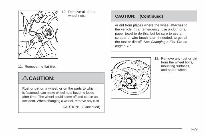
10. Remove all of thewheel nuts.
11. Remove the flat tire.
{CAUTION:
Rust or dirt on a wheel, or on the parts to which itis fastened, can make wheel nuts become looseafter time. The wheel could come off and cause anaccident. When changing a wheel, remove any rust
CAUTION: (Continued)
CAUTION: (Continued)
or dirt from places where the wheel attaches tothe vehicle. In an emergency, use a cloth or apaper towel to do this; but be sure to use ascraper or wire brush later, if needed, to get allthe rust or dirt off. See Changing a Flat Tire onpage 5-70.
12. Remove any rust or dirtfrom the wheel bolts,mounting surfaces,and spare wheel.
5-77

13. Place the compact spare tire on the wheel-mountingsurface.
{CAUTION:
Never use oil or grease on bolts or nuts becausethe nuts might come loose. The vehicle’s wheelcould fall off, causing a crash.
14. Reinstall the wheel nuts. Tighten each nut by handuntil the wheel is held against the hub.
15. Lower the vehicle by turning the jack handlecounterclockwise.
{CAUTION:
Wheel nuts that are improperly or incorrectlytightened can cause the wheels to become loose orcome off. The wheel nuts should be tightened witha torque wrench to the proper torque specificationafter replacing. Follow the torque specificationsupplied by the aftermarket manufacturer whenusing accessory locking wheel nuts. See Capacitiesand Specifications on page 5-97 for originalequipment wheel nut torque specifications.
Notice: Improperly tightened wheel nuts canlead to brake pulsation and rotor damage. To avoidexpensive brake repairs, evenly tighten the wheelnuts in the proper sequence and to the proper torquespecification. See Capacities and Specifications onpage 5-97 for the wheel nut torque specification.
5-78

16. Tighten the wheel nutsfirmly in a crisscrosssequence, as shown.
17. Lower the jack all the way and remove the jackfrom under the vehicle.
18. Tighten the wheel nuts firmly with the wheelwrench.
When reinstalling the wheel cover or center cap on thefull-size tire, tighten all five plastic caps hand snug withthe aid of the wheel wrench and tighten them with thewheel wrench an additional one-quarter of a turn.
Notice: Wheel covers will not fit on your vehicle’scompact spare. If you try to put a wheel cover onthe compact spare, the cover or the spare could bedamaged.
Storing a Flat or Spare Tire andTools
{CAUTION:
Storing a jack, a tire, or other equipment in thepassenger compartment of the vehicle couldcause injury. In a sudden stop or collision, looseequipment could strike someone. Store all thesein the proper place.
To store the flat or spare tire and tools:1. Place the wheel wrench into the bag.2. Use the hook and loop fastener straps to secure
the bag to the fully collapsed jack.
3. Install the jack in theleft side panel of cargoarea and secure withthe wing bolt.
5-79

4. Remove the wheel stow rod from the left side of thefloor compartment.
5. Screw the threaded wheel stow rod onto the sparetire bracket. The final position of the wheel stow rodmust be turned to the farthest forward position.
6. Remove the cap, if your vehicle has one, from thecenter of the load floor. Position the rod throughthe hole. Replace the rear compartment load floorover the wheel stow rod through the hole in thefloor.
7. Place the flat, or damaged tire, face down, on theload floor with the threaded wheel stow rod stickingup through the center hole of the wheel.
8. Install the nut onto the wheel stow rod and tighten.
9. Install the rear compartment storage panel/coverin the middle position. See Rear CompartmentStorage Panel/Cover on page 2-44 for moreinformation.
The compact spare is for temporary use only. Replacethe compact spare tire with a full-size tire as soonas you can.
5-80

Compact Spare Tire
{CAUTION:
Driving with more than one compact spare tire ata time could result in loss of braking and handling.This could lead to a crash and you or others couldbe injured. Use only one compact spare tire ata time.
Although the compact spare tire was fully inflatedwhen the vehicle was new, it can lose air after a time.Check the inflation pressure regularly. It should be60 psi (420 kPa).
After installing the compact spare on the vehicle, stopas soon as possible and make sure the spare tire iscorrectly inflated. The compact spare is made to performwell at speeds up to 65 mph (105 km/h) for distances
up to 3,000 miles (5 000 km), so you can finish your tripand have the full-size tire repaired or replaced at yourconvenience. Of course, it is best to replace the sparewith a full-size tire as soon as possible. The spare tirewill last longer and be in good shape in case it is neededagain.
Notice: When the compact spare is installed,do not take the vehicle through an automatic carwash with guide rails. The compact spare canget caught on the rails which can damage the tire,wheel and other parts of the vehicle.
Do not use the compact spare on other vehicles.
And do not mix the compact spare tire or wheel withother wheels or tires. They will not fit. Keep thespare tire and its wheel together.
Notice: Tire chains will not fit the compact spare.Using them can damage the vehicle and can damagethe chains too. Do not use tire chains on thecompact spare.
5-81

Appearance Care
Interior CleaningThe vehicle’s interior will continue to look its best if itis cleaned often. Although not always visible, dust anddirt can accumulate on the upholstery. Dirt can damagecarpet, fabric, leather, and plastic surfaces. Regularvacuuming is recommended to remove particles fromthe upholstery. It is important to keep the upholsteryfrom becoming and remaining heavily soiled. Soilsshould be removed as quickly as possible. The vehicle’sinterior may experience extremes of heat that couldcause stains to set rapidly.
Lighter colored interiors may require more frequentcleaning. Use care because newspapers and garmentsthat transfer color to home furnishings may alsotransfer color to the vehicle’s interior.
When cleaning the vehicle’s interior, only use cleanersspecifically designed for the surfaces being cleaned.Permanent damage may result from using cleaners on
surfaces for which they were not intended. Use glasscleaner only on glass. Remove any accidental over-sprayfrom other surfaces immediately. To prevent over-spray,apply cleaner directly to the cleaning cloth.
Notice: Using abrasive cleaners when cleaningglass surfaces on the vehicle, could scratchthe glass and/or cause damage to the rear windowdefogger. When cleaning the glass on the vehicle,use only a soft cloth and glass cleaner.
Many cleaners contain solvents that may becomeconcentrated in the vehicle’s breathing space. Beforeusing cleaners, read and adhere to all safety instructionson the label. While cleaning the vehicle’s interior,maintain adequate ventilation by opening the vehicle’sdoors and windows.
Dust may be removed from small buttons and knobsusing a small brush with soft bristles.
Products that remove odors from the vehicle’supholstery and clean the vehicle’s glass can beobtained from your dealer/retailer.
5-82

Do not clean the vehicle using:
• A knife or any other sharp object to remove a soilfrom any interior surface.
• A stiff brush. It can cause damage to the vehicle’sinterior surfaces.
• Heavy pressure or aggressive rubbing with acleaning cloth. Use of heavy pressure can damagethe interior and does not improve the effectivenessof soil removal.
• Laundry detergents or dishwashing soaps withdegreasers can leave residue that streaks andattracts dirt. For liquid cleaners, about 20 dropsper gallon (3.78 L) of water is a good guide.Use only mild, neutral-pH soaps.
• Too much cleaner that saturates the upholstery.
• Organic solvents such as naptha, alcohol, etc. thatcan damage the vehicle’s interior.
Fabric/CarpetUse a vacuum cleaner with a soft brush attachmentfrequently to remove dust and loose dirt. A canistervacuum with a beater bar in the nozzle may onlybe used on floor carpet and carpeted floor mats.For any soil, always try to remove it first with plainwater or club soda. Before cleaning, gently removeas much of the soil as possible using one of thefollowing techniques:
• For liquids: gently blot the remaining soil with apaper towel. Allow the soil to absorb into thepaper towel until no more can be removed.
• For solid dry soils: remove as much as possibleand then vacuum.
5-83

To clean:
1. Saturate a lint-free, clean white cloth with water orclub soda.
2. Wring the cloth to remove excess moisture.
3. Start on the outside edge of the soil and gently rubtoward the center. Continue cleaning, using a cleanarea of the cloth each time it becomes soiled.
4. Continue to gently rub the soiled area until thecleaning cloth remains clean.
5. If the soil is not completely removed, use a mildsoap solution and repeat the cleaning processthat was used with plain water.
If any of the soil remains, a commercial fabric cleaneror spot lifter may be necessary. When a commercialupholstery cleaner or spot lifter is to be used, testa small hidden area for colorfastness first. If thelocally cleaned area gives any impression that aring formation may result, clean the entire surface.
After the cleaning process has been completed, a papertowel can be used to blot excess moisture from thefabric or carpet.
LeatherA soft cloth dampened with water can be used toremove dust. If a more thorough cleaning is necessary,a soft cloth dampened with a mild soap solution can beused. Allow the leather to dry naturally. Do not use heatto dry. Never use steam to clean leather. Never use spotlifters or spot removers on leather. Many commercialleather cleaners and coatings that are sold to preserveand protect leather may permanently change theappearance and feel of the leather and are notrecommended. Do not use silicone or wax-basedproducts, or those containing organic solvents toclean the vehicle’s interior because they can alter theappearance by increasing the gloss in a non-uniformmanner. Never use shoe polish on leather.
5-84

Instrument Panel, Vinyl, and OtherPlastic SurfacesA soft cloth dampened with water may be used toremove dust. If a more thorough cleaning is necessary,a clean soft cloth dampened with a mild soap solutioncan be used to gently remove dust and dirt. Never usespot lifters or removers on plastic surfaces. Manycommercial cleaners and coatings that are sold topreserve and protect soft plastic surfaces maypermanently change the appearance and feel of theinterior and are not recommended. Do not use siliconeor wax-based products, or those containing organicsolvents to clean the vehicle’s interior because theycan alter the appearance by increasing the gloss ina non-uniform manner.
Some commercial products may increase gloss on theinstrument panel. The increase in gloss may causeannoying reflections in the windshield and even makeit difficult to see through the windshield under certainconditions.
Care of Safety BeltsKeep belts clean and dry.
{CAUTION:
Do not bleach or dye safety belts. It may severelyweaken them. In a crash, they might not be ableto provide adequate protection. Clean safety beltsonly with mild soap and lukewarm water.
WeatherstripsSilicone grease on weatherstrips will make them lastlonger, seal better, and not stick or squeak. Applysilicone grease with a clean cloth. During very cold,damp weather frequent application may be required.See Recommended Fluids and Lubricants on page 6-13.
5-85

Washing Your VehicleThe best way to preserve the vehicle’s finish is to keepit clean by washing it often.
Notice: Certain cleaners contain chemicals that candamage the emblems or nameplates on the vehicle.Check the cleaning product label. If it states thatit should not be used on plastic parts, do not useit on the vehicle or damage may occur and it wouldnot be covered by the warranty.
Do not wash the vehicle in direct sunlight. Use a carwashing soap. Do not use cleaning agents that arepetroleum based or that contain acid or abrasives,as they can damage the paint, metal or plastic on thevehicle. Approved cleaning products can be obtainedfrom your dealer/retailer. Follow all manufacturers’directions regarding correct product usage, necessarysafety precautions and appropriate disposal of anyvehicle care product.
Rinse the vehicle well, before washing and after toremove all cleaning agents completely. If they areallowed to dry on the surface, they could stain.
Dry the finish with a soft, clean chamois or an all-cottontowel to avoid surface scratches and water spotting.
High pressure car washes may cause water to enterthe vehicle. Avoid using high pressure washes closerthan 12 inches (30 cm) to the surface of the vehicle.Use of power washers exceeding 1,200 psi (8 274 kPa)can result in damage or removal of paint and decals.
Cleaning Exterior Lamps/LensesUse only lukewarm or cold water, a soft cloth and acar washing soap to clean exterior lamps and lenses.Follow instructions under Washing Your Vehicle onpage 5-86.
5-86

Finish CareOccasional waxing or mild polishing of the vehicle byhand may be necessary to remove residue from the paintfinish. Approved cleaning products can be obtained fromyour dealer/retailer.
If the vehicle has a basecoat/clearcoat paint finish,the clearcoat gives more depth and gloss to the coloredbasecoat. Always use waxes and polishes that arenon-abrasive and made for a basecoat/clearcoatpaint finish.
Notice: Machine compounding or aggressivepolishing on a basecoat/clearcoat paint finishmay damage it. Use only non-abrasive waxes andpolishes that are made for a basecoat/clearcoatpaint finish on the vehicle.
Foreign materials such as calcium chloride and othersalts, ice melting agents, road oil and tar, tree sap, birddroppings, chemicals from industrial chimneys, etc.,can damage the vehicle’s finish if they remain onpainted surfaces. Wash the vehicle as soon as possible.If necessary, use non-abrasive cleaners that are markedsafe for painted surfaces to remove foreign matter.
Exterior painted surfaces are subject to aging, weatherand chemical fallout that can take their toll over aperiod of years. To help keep the paint finish lookingnew, keep the vehicle garaged or covered wheneverpossible.
Protecting Exterior Bright Metal PartsBright metal parts should be cleaned regularly to keeptheir luster. Washing with water is all that is usuallyneeded. However, chrome polish may be used onchrome or stainless steel trim, if necessary.
Use special care with aluminum trim. To avoiddamaging protective trim, never use auto or chromepolish, steam or caustic soap to clean aluminum.A coating of wax, rubbed to high polish, is recommendedfor all bright metal parts.
Windshield and Wiper BladesClean the outside of the windshield with glass cleaner.
Clean the rubber blades using a lint free cloth orpaper towel soaked with windshield washer fluid ora mild detergent. Wash the windshield thoroughlywhen cleaning the blades. Bugs, road grime, sap,and a buildup of vehicle wash/wax treatments maycause wiper streaking. Replace the wiper blades ifthey are worn or damaged.
Wipers can be damaged by:
• Extreme dusty conditions
• Sand and salt
• Heat and sun
• Snow and ice, without proper removal
5-87

Aluminum or Chrome-Plated Wheelsand TrimThe vehicle may have either aluminum or chrome-platedwheels.
Keep the wheels clean using a soft clean cloth with mildsoap and water. Rinse with clean water. After rinsingthoroughly, dry with a soft clean towel. A wax may thenbe applied.
Notice: Chrome wheels and other chrome trim maybe damaged if the vehicle is not washed after drivingon roads that have been sprayed with magnesium,calcium or sodium chloride. These chlorides areused on roads for conditions such as ice and dust.Always wash the vehicle’s chrome with soap andwater after exposure.
Notice: Using strong soaps, chemicals, abrasivepolishes, cleaners, brushes, or cleaners that containacid on aluminum or chrome-plated wheels, coulddamage the surface of the wheel(s). The repairswould not be covered by the vehicle warranty.Use only approved cleaners on aluminum orchrome-plated wheels.
The surface of these wheels is similar to the paintedsurface of the vehicle. Do not use strong soaps,chemicals, abrasive polishes, abrasive cleaners,
cleaners with acid, or abrasive cleaning brusheson them because they could damage the surface.Do not use chrome polish on aluminum wheels.
Notice: Using chrome polish on aluminum wheelscould damage the wheels. The repairs would notbe covered by the vehicle warranty. Use chromepolish on chrome wheels only.
Use chrome polish only on chrome-plated wheels, butavoid any painted surface of the wheel, and buff offimmediately after application.
Notice: Driving the vehicle through an automaticcar wash that has silicone carbide tire cleaningbrushes, could damage the aluminum orchrome-plated wheels. The repairs would not becovered by the vehicle warranty. Never drive avehicle that has aluminum or chrome-plated wheelsthrough an automatic car wash that uses siliconecarbide tire cleaning brushes.
TiresTo clean the tires, use a stiff brush with tire cleaner.
Notice: Using petroleum-based tire dressingproducts on the vehicle may damage the paint finishand/or tires. When applying a tire dressing, alwayswipe off any overspray from all painted surfaceson the vehicle.
5-88

Sheet Metal DamageIf the vehicle is damaged and requires sheet metalrepair or replacement, make sure the body repair shopapplies anti-corrosion material to parts repaired orreplaced to restore corrosion protection.
Original manufacturer replacement parts will providethe corrosion protection while maintaining the vehiclewarranty.
Finish DamageAny stone chips, fractures or deep scratches in thefinish should be repaired right away. Bare metalwill corrode quickly and may develop into majorrepair expense.
Minor chips and scratches can be repaired with touch-upmaterials available from your dealer/retailer. Largerareas of finish damage can be corrected in yourdealer’s/retailer’s body and paint shop.
Underbody MaintenanceChemicals used for ice and snow removal and dustcontrol can collect on the underbody. If these are notremoved, corrosion and rust can develop on theunderbody parts such as fuel lines, frame, floor pan,and exhaust system even though they have corrosionprotection.
At least every spring, flush these materials from theunderbody with plain water. Clean any areas where mudand debris can collect. Dirt packed in close areas ofthe frame should be loosened before being flushed.Your dealer/retailer or an underbody car washingsystem can do this.
Chemical Paint SpottingSome weather and atmospheric conditions can createa chemical fallout. Airborne pollutants can fall upon andattack painted surfaces on the vehicle. This damage cantake two forms: blotchy, ring-shaped discolorations, andsmall, irregular dark spots etched into the paint surface.
Although no defect in the paint job causes this, we willrepair, at no charge to the owner, the surfaces ofnew vehicles damaged by this fallout condition within12 months or 12,000 miles (20 000 km) of purchase,whichever occurs first.
5-89

Vehicle Identification
Vehicle Identification Number (VIN)
This is the legal identifier for the vehicle. It appears ona plate in the front corner of the instrument panel, on thedriver side. It can be seen through the windshield fromoutside the vehicle. The VIN also appears on the VehicleCertification and Service Parts labels and the certificatesof title and registration.
Engine IdentificationThe eighth character in the VIN is the engine code.This code helps identify the vehicle’s engine,specifications, and replacement parts. See “EngineSpecifications” under Capacities and Specificationson page 5-97 for the vehicle’s engine code.
Service Parts Identification LabelThis label is on the inside of the glove box. It isvery helpful if parts need to be ordered. The labelhas the following information:
• Vehicle Identification Number (VIN)
• Model designation
• Paint information
• Production options and special equipment
Do not remove this label from the vehicle.
5-90

Electrical System
Add-On Electrical EquipmentNotice: Do not add anything electrical to thevehicle unless you check with your dealer/retailerfirst. Some electrical equipment can damagethe vehicle and the damage would not be coveredby the vehicle’s warranty. Some add-on electricalequipment can keep other components fromworking as they should.
Add-on equipment can drain the vehicle battery, even ifthe vehicle is not operating.
The vehicle has an airbag system. Before attempting toadd anything electrical to the vehicle, see ServicingYour Airbag-Equipped Vehicle on page 1-68.
Windshield Wiper FusesThe windshield wiper motor is protected by a circuitbreaker and a fuse. If the motor overheats due to heavysnow or ice, the wiper will stop until the motor cools.If the overload is caused by some electrical problem,have it fixed.
Fuses and Circuit BreakersThe wiring circuits in the vehicle are protected fromshort circuits by fuses and circuit breakers. This greatlyreduces the chance of circuit overload and fire causedby electrical problems.
The vehicle has an underhood fuse block and aninstrument panel fuse block.
To identify and check fuses, circuit breakers, and relays,refer to the Fuse Usage Chart on the inside surfaceof the fuse panel door.
5-91
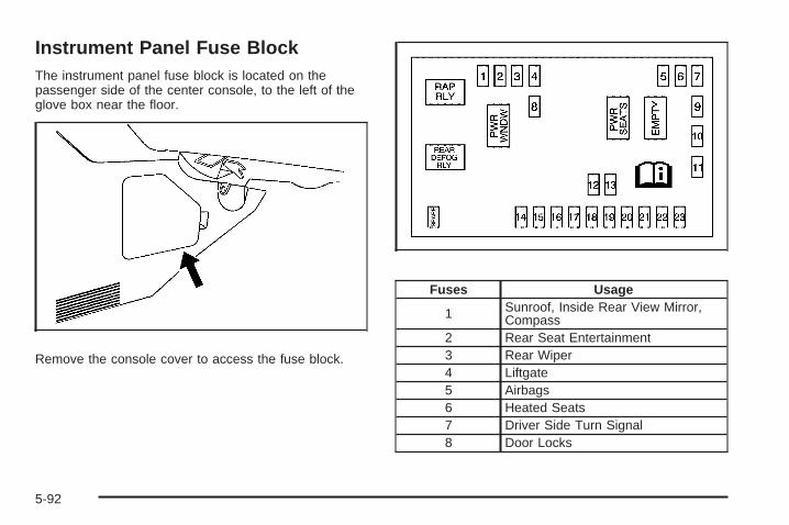
Instrument Panel Fuse BlockThe instrument panel fuse block is located on thepassenger side of the center console, to the left of theglove box near the floor.
Remove the console cover to access the fuse block.
Fuses Usage
1 Sunroof, Inside Rear View Mirror,Compass
2 Rear Seat Entertainment3 Rear Wiper4 Liftgate5 Airbags6 Heated Seats7 Driver Side Turn Signal8 Door Locks
5-92

Fuses Usage
9 Automatic Occupant SensingModule
10 Power Mirrors11 Passenger Side Turn Signal12 Amplifier13 Steering Wheel Illumination14 Infotainment
15 Climate Control System,Remote Function Actuator
16 Canister Vent17 Radio18 Cluster19 Ignition Switch20 Body Control Module21 Communications Integration Module
22 Center High-Mounted Stoplamp,Dimmer
23 Interior Lights
Relays UsageRAP RLY Retained Accessory Power Relay
REAR DEFOGRLY Rear Defogger Relay
CircuitBreakers Usage
PWR WNDW Power WindowsPWR SEATS Power Seats
EMPTY Empty
Engine Compartment Fuse Block
The engine compartment fuse block is located on thedriver side of the engine compartment.
See Engine Compartment Overview on page 5-12 formore information on location.
5-93

To remove the fuse block cover, release the rear ofthe cover first, by unlocking both of the tabs in the back.Then lift the cover off. Do not lift the front of the cover untilthe tabs at the rear have been unlocked. To reinstall, fittogether the tabs located on the front of the cover, andpush down on the cover until the tabs on the rear of thecover click into place.
Notice: Spilling liquid on any electrical componentson the vehicle may damage it. Always keep thecovers on any electrical component.
5-94

Fuses Usage1 Cooling Fan 22 Cooling Fan 13 Auxiliary Power4 Rear HVAC5 Spare6 Sun Roof7 Antilock Brake System8 Air Conditioning Clutch9 Driver Side Low-Beam
10 Daytime Running Lamp 211 Passenger Side High-Beam12 Passenger Side Park Lamp13 Horn14 Driver Side Park Lamp15 Starter
16 Electronic Throttle Control,Engine Control Module
17 Emission Device 118 Even Coils, Injectors19 Odd Coils, Injectors20 Emission Device 221 Spare22 Powertrain Control Module, Ignition23 Transmission
Fuses Usage24 Mass Airflow Sensor25 Airbag Display26 Spare27 Stoplamp28 Passenger Side Low-Beam29 Driver Side High-Beam30 Battery Main 332 Spare33 Engine Control Module, Battery
34 Transmission Control Module,Battery
35 Trailer Park Lamp36 Front Wiper
37 Driver Side Trailer Stoplamp,Turn Signal
38 Spare39 Fuel Pump40 Not Used41 All-Wheel Drive42 Regulated Voltage Control
43 Passenger Side Trailer Stoplamp,Turn Signal
44 Spare45 Front, Rear Washer
5-95

Fuses Usage48 Rear Defogger49 Antilock Brake System Motor50 Battery Main 252 Daytime Running Lamps53 Fog Lamps54 Climate Control System Blower57 Battery Main 163 Electric Power Steering
When changing relays, observe the location of thenotch on the old relay. Install new relays with the notchin the same location.
Relays Usage31 Ignition Main46 Air Conditioning Compressor Clutch47 Powertrain51 Spare55 Crank56 Fan 1
58 Passenger Side Trailer Stoplamp,Turn Signal
59 Driver Side Trailer Stoplamp,Turn Signal
60 Fan 361 Fan 262 Fuel Pump
Misc. UsagePLR Fuse Puller
5-96

Capacities and SpecificationsThe following approximate capacities are given in English and metric conversions. See Recommended Fluids andLubricants on page 6-13 for more information.
Application
Capacities
English Metric
Air Conditioning Refrigerant R134a
For the air conditioning system refrigerant chargeamount, see the refrigerant caution label located
under the hood. See your dealer for moreinformation.
Cooling System
3.4L V6 Engine 10.5 qt 9.9 L
3.6L V6 Engine 11.0 qt 10.4 L
Engine Oil with Filter
3.4L V6 Engine 4.5 qt 4.3 L
3.6L V6 Engine 5.5 qt 5.2 L
5-97

Application
Capacities
English Metric
Fuel Tank
Front-Wheel Drive 20.5 gal 77.6 L
All-Wheel Drive 16.6 gal 62.8 L
Transmission Fluid
Automatic 5-Speed AF33 Transmission 4.1 qt 3.9 L
Automatic 6-Speed 6T70 Transmission 9.5 qt 9.0 L
Wheel Nut Torque 100 lb ft 140 Y
All capacities are approximate. When adding, be sure to fill to the approximate level, as recommended in thismanual. Recheck fluid level after filling.
Engine SpecificationsEngine VIN Code Transmission Spark Plug Gap
3.4L V6 F Automatic 0.060 in (1.52 mm)
3.6L V6 7 Automatic 0.040 in (1.01 mm)
5-98

Maintenance Schedule ......................................6-2Introduction ...................................................6-2Maintenance Requirements ..............................6-2Your Vehicle and the Environment ....................6-2Using the Maintenance Schedule ......................6-2Scheduled Maintenance ...................................6-4Additional Required Services ............................6-7Maintenance Footnotes ...................................6-8
Owner Checks and Services ..........................6-10At Each Fuel Fill ..........................................6-10At Least Once a Month .................................6-11At Least Once a Year ...................................6-11Recommended Fluids and Lubricants ...............6-13Maintenance Replacement Parts .....................6-15Engine Drive Belt Routing ..............................6-16Maintenance Record .....................................6-17
Section 6 Maintenance Schedule
6-1

Maintenance Schedule
IntroductionImportant: Keep engine oil at the proper level andchange as recommended.
Have you purchased the GM Protection Plan? The Plansupplements the vehicle warranties. See the Warrantyand Owner Assistance booklet or your dealer/retailer fordetails.
Maintenance RequirementsNotice: Maintenance intervals, checks, inspections,replacement parts, and recommended fluids andlubricants as prescribed in this manual are necessaryto keep this vehicle in good working condition.Any damage caused by failure to follow scheduledmaintenance might not be covered by the vehiclewarranty.
Your Vehicle and the EnvironmentProper vehicle maintenance not only helps to keepthe vehicle in good working condition, but also helpsthe environment. All recommended maintenance isimportant. Improper vehicle maintenance can even affectthe quality of the air we breathe. Improper fluid levels orthe wrong tire inflation can increase the level of emissionsfrom the vehicle. To help protect the environment, and tokeep the vehicle in good condition, be sure to maintainthe vehicle properly.
Using the Maintenance ScheduleWe want to help keep this vehicle in good workingcondition. But we do not know exactly how you will driveit. You might drive very short distances only a few timesa week. Or you might drive long distances all the time invery hot, dusty weather. You might use the vehicle inmaking deliveries. Or you might drive it to work, to doerrands, or in many other ways.
Because of all the different ways people use theirvehicles, maintenance needs vary. You might need morefrequent checks and replacements. So please read thefollowing and note how you drive. If you have anyquestions on how to keep the vehicle in good condition,see your dealer/retailer.
6-2

This schedule is for vehicles that:
• carry passengers and cargo within recommendedlimits on the Tire and Loading Information label.See Loading the Vehicle on page 4-20.
• are driven on reasonable road surfaces within legaldriving limits.
• use the recommended fuel. See Gasoline Octaneon page 5-5.
The services in Scheduled Maintenance on page 6-4should be performed when indicated. See AdditionalRequired Services on page 6-7 and MaintenanceFootnotes on page 6-8 for further information.
{CAUTION:
Performing maintenance work on a vehicle can bedangerous. In trying to do some jobs, you can beseriously injured. Do your own maintenance workonly if you have the required know-how and theproper tools and equipment for the job. If you haveany doubt, see your dealer/retailer to have aqualified technician do the work. See Doing YourOwn Service Work on page 5-4.
Some maintenance services can be complex. So, unlessyou are technically qualified and have the necessaryequipment, have your dealer/retailer do these jobs.
When you go to your dealer/retailer for service, trainedand supported service technicians will perform thework using genuine parts.
To purchase service information, see ServicePublications Ordering Information on page 7-16.
Owner Checks and Services on page 6-10 tells whatshould be checked, when to check it, and what can easilybe done to help keep the vehicle in good condition.
The proper replacement parts, fluids, and lubricants touse are listed in Recommended Fluids and Lubricants onpage 6-13 and Maintenance Replacement Parts onpage 6-15. When the vehicle is serviced, make surethese are used. All parts should be replaced and allnecessary repairs done before you or anyone else drivesthe vehicle. We recommend the use of genuine partsfrom your dealer/retailer.
6-3
Scheduled MaintenanceWhen the change engine oil light and/or CHANGEENGINE OIL SOON message displays, service isrequired for the vehicle. Have the vehicle serviced assoon as possible within the next 600 miles (1 000 km).It is possible that, if driving under the best conditions,the engine oil life system may not indicate that vehicleservice is necessary for over a year. However, the engineoil and filter must be changed at least once a year and atthis time the system must be reset. Your dealer/retailerhas trained service technicians who will perform thiswork using genuine parts and reset the system.
If the engine oil life system is ever reset accidentally,service the vehicle within 3,000 miles (5 000 km) sincethe last service. Remember to reset the oil life systemwhenever the oil is changed. See Engine Oil Life Systemon page 5-18 for information on the Engine Oil LifeSystem and resetting the system.
When the change engine oil light and/or CHANGEENGINE OIL SOON message appears, certain services,checks, and inspections are required. Required servicesare described in the following for “Maintenance I” and“Maintenance II.” Generally, it is recommended that thefirst service be Maintenance I, the second service beMaintenance II, and then alternate Maintenance I andMaintenance II thereafter. However, in some cases,Maintenance II may be required more often.
Maintenance I — Use Maintenance I if the light/message displays within 10 months since the vehiclewas purchased or Maintenance II was performed.
Maintenance II — Use Maintenance II if the previousservice performed was Maintenance I. Always useMaintenance II whenever the light/message displays10 months or more since the last service or if the light/message has not come on at all for one year.
6-4

Scheduled MaintenanceService Maintenance I Maintenance II
Change engine oil and filter. See Engine Oil on page 5-15. Reset oil lifesystem. See Engine Oil Life System on page 5-18. An Emission ControlService.
• •
Visually check for any leaks or damage. See footnote (k). • •
Inspect engine air cleaner filter. If necessary, replace filter. See Engine AirCleaner/Filter on page 5-20. See footnote (l). •
Rotate tires and check inflation pressures and wear. See Tire Inspection andRotation on page 5-62 and “Tire Wear Inspection” in At Least Once a Month onpage 6-11.
• •
Inspect brake system. See footnote (a). • •
Check engine coolant, power steering fluid (3.6L V6 engine only), andwindshield washer fluid levels and add fluid as needed. • •
6-5

Scheduled Maintenance (cont’d)Service Maintenance I Maintenance II
Perform any needed additional services. See “Additional Required Services”in this section. • •
Inspect suspension and steering components. See footnote (b). •
Inspect engine cooling system. See footnote (c). •
Inspect wiper blades. See footnote (d). •
Inspect restraint system components. See footnote (e). •
Lubricate body components. See footnote (f). •
Replace passenger compartment air filter. See footnote (g). •
3.6L V6 Engine Only: Check automatic transmission fluid level and add fluidas needed. •
Inspect throttle system. See footnote (j). •
6-6

Additional Required ServicesThe following services should be performed at the first maintenance service (I or II) after the indicated miles(kilometers) shown for each item.
Additional Required Services
Service and Miles (Kilometers) 25,000(40 000)
50,000(80 000)
75,000(120 000)
100,000(160 000)
125,000(200 000)
150,000(240 000)
Inspect fuel system for damage or leaks. • • • • • •Inspect exhaust system for loose ordamaged components. • • • • • •
Replace engine air cleaner filter. SeeEngine Air Cleaner/Filter on page 5-20. • • •
Change automatic transmission fluid(severe service). See footnote (h). • • •
Change automatic transmission fluid(normal service). •
Change transfer case fluid (severeservice). See footnote (n). • • •
Change transfer case fluid (normalservice). See footnote (o). • •
Replace spark plugs and inspect sparkplug wires. An Emission Control Service. •
6-7

Additional Required Services (cont’d)
Service and Miles (Kilometers) 25,000(40 000)
50,000(80 000)
75,000(120 000)
100,000(160 000)
125,000(200 000)
150,000(240 000)
Engine cooling system service (or everyfive years, whichever occurs first).An Emission Control Service.See footnote (i).
•
Inspect engine accessory drive belt.An Emission Control Service.See footnote (m).
•
Maintenance Footnotes(a) Visually inspect brake lines and hoses for properhook-up, binding, leaks, cracks, chafing, etc. Inspectdisc brake pads for wear and rotors for surfacecondition. Inspect other brake parts, including calipers,parking brake, etc. Check parking brake adjustment.
(b) Visually inspect front and rear suspension andsteering system for damaged, loose, or missingparts or signs of wear. Visually check constant velocityjoints, rubber boots, and axle seals for leaks. With3.4L V6 engine: Inspect electric power steering cablesfor proper hook-up, binding, cracks, chafing, etc. With3.6L V6 engine: Inspect hydraulic power steering linesand hoses for proper hook-up, binding, leaks, cracks,chafing, etc.
(c) Visually inspect hoses and have them replaced if theyare cracked, swollen, or deteriorated. Inspect all pipes,fittings and clamps; replace with genuine parts asneeded. To help ensure proper operation, a pressure testof the cooling system and pressure cap and cleaning theoutside of the radiator and air conditioning condenser isrecommended at least once a year.
(d) Inspect wiper blades for wear, cracking, orcontamination. Clean the windshield and wiper blades,if contaminated. Replace wiper blades that are worn ordamaged. See Windshield Wiper Blade Replacementon page 5-47 and Windshield and Wiper Blades onpage 5-87 for more information.
6-8

(e) Make sure the safety belt reminder light and safetybelt assemblies are working properly. Look for anyother loose or damaged safety belt system parts. If yousee anything that might keep a safety belt systemfrom doing its job, have it repaired. Have any torn orfrayed safety belts replaced. Also see Checkingthe Restraint Systems on page 1-70.
(f) Lubricate all key lock cylinders, hood latch assemblies,secondary latches, pivots, spring anchor and releasepawl, hood and door hinges, rear folding seats, andliftgate hinges. More frequent lubrication may be requiredwhen exposed to a corrosive environment. Applyingsilicone grease on weatherstrips with a clean cloth willmake them last longer, seal better, and not stick orsqueak.
(g) If driving regularly under dusty conditions, the filtermay require replacement more often.
(h) Change automatic transmission fluid if the vehicle ismainly driven under one or more of these conditions:
− In heavy city traffic where the outside temperatureregularly reaches 90°F (32°C) or higher.
− In hilly or mountainous terrain.− When doing frequent trailer towing.− Uses such as found in taxi, police, or delivery
service.
(i) Drain, flush, and refill cooling system. This service canbe complex; you should have your dealer/retailer performthis service. See Engine Coolant on page 5-23 for what touse. Inspect hoses. Clean radiator, condenser, pressurecap, and filler neck. Pressure test the cooling system andpressure cap.
(j) Check system for interference or binding and fordamaged or missing parts. Replace parts as needed.Replace any components that have high effort orexcessive wear.
6-9

(k) A fluid loss in any vehicle system could indicate aproblem. Have the system inspected and repairedand the fluid level checked. Add fluid if needed.
(l) If driving regularly under dusty conditions, inspect thefilter at each engine oil change.
(m) Visually inspect belt for fraying, excessive cracks, orobvious damage. Replace belt if necessary.
(n) Severe service is when the vehicle is mainly drivenunder one or more of these conditions:
− In heavy city traffic where the outside temperatureregularly reaches 90°F (32°C) or higher.
− In hilly or mountainous terrain.− When doing frequent trailer towing.− Uses such as found in taxi, police, or delivery
service.
(o) Change the fluid the first time the vehicle is servicedafter 100,000 miles (166 000 km) and when thevehicle is serviced after each subsequent 50,000 miles(83 000 km).
Owner Checks and ServicesThese owner checks and services should be performedat the intervals specified to help ensure vehicle safety,dependability, and emission control performance. Yourdealer/retailer can assist with these checks and services.
Be sure any necessary repairs are completed at once.Whenever any fluids or lubricants are added to thevehicle, make sure they are the proper ones, as shownin Recommended Fluids and Lubricants on page 6-13.
At Each Fuel FillIt is important to perform these underhood checks ateach fuel fill.
Engine Oil Level Check
Notice: It is important to check the engine oilregularly and keep it at the proper level. Failure tokeep the engine oil at the proper level can causedamage to the engine not covered by the vehiclewarranty.
Check the engine oil level and add the proper oil ifnecessary. See Engine Oil on page 5-15.
6-10

Engine Coolant Level CheckCheck the engine coolant level and add DEX-COOL®
coolant mixture if necessary. See Engine Coolanton page 5-23.
Windshield Washer Fluid Level CheckCheck the windshield washer fluid level in the windshieldwasher fluid reservoir and add the proper fluid ifnecessary.
At Least Once a Month
Tire Inflation CheckInspect the vehicle’s tires and make sure they areinflated to the correct pressures. Do not forget tocheck the spare tire. See Inflation - Tire Pressure onpage 5-55. Check to make sure the spare tire is storedsecurely. See Changing a Flat Tire on page 5-70.
Tire Wear InspectionTire rotation may be required for high mileage highwaydrivers prior to the Engine Oil Life System servicenotification. Check the tires for wear and, if necessary,rotate the tires. See Tire Inspection and Rotation onpage 5-62.
At Least Once a Year
Starter Switch Check
{CAUTION:
When you are doing this inspection, the vehiclecould move suddenly. If the vehicle moves, you orothers could be injured.
1. Before starting this check, be sure there is enoughroom around the vehicle.
2. Firmly apply both the parking brake and the regularbrake. See Parking Brake on page 2-31.Do not use the accelerator pedal, and be ready toturn off the engine immediately if it starts.
3. Try to start the engine in each gear. The vehicleshould start only in P (Park) or N (Neutral). If thevehicle starts in any other position, contactyour dealer/retailer for service.
6-11

Automatic Transmission Shift LockControl System Check
{CAUTION:
When you are doing this inspection, the vehiclecould move suddenly. If the vehicle moves, you orothers could be injured.
1. Before starting this check, be sure there is enoughroom around the vehicle. It should be parked on alevel surface.
2. Firmly apply the parking brake. See Parking Brakeon page 2-31.Be ready to apply the regular brake immediately ifthe vehicle begins to move.
3. With the engine off, turn the ignition to ON/RUN,but do not start the engine. Without applying theregular brake, try to move the shift lever outof P (Park) with normal effort. If the shift levermoves out of P (Park), contact your dealer/retailerfor service.
Ignition Transmission Lock CheckWhile parked, and with the parking brake set, try to turnthe ignition to LOCK/OFF in each shift lever position.
• The ignition should turn to LOCK/OFF onlywhen the shift lever is in P (Park).
• The ignition key should come out only inLOCK/OFF.
Contact your dealer/retailer if service is required.
6-12

Parking Brake and AutomaticTransmission P (Park) MechanismCheck
{CAUTION:
When you are doing this check, the vehicle couldbegin to move. You or others could be injured andproperty could be damaged. Make sure there isroom in front of the vehicle in case it begins to roll.Be ready to apply the regular brake at once shouldthe vehicle begin to move.
Park on a fairly steep hill, with the vehicle facing downhill.Keeping your foot on the regular brake, set the parkingbrake.• To check the parking brake’s holding ability: With the
engine running and the transmission in N (Neutral),slowly remove foot pressure from the regular brakepedal. Do this until the vehicle is held by the parkingbrake only.
• To check the P (Park) mechanism’s holding ability:With the engine running, shift to P (Park). Thenrelease the parking brake followed by the regularbrake.
Contact your dealer/retailer if service is required.
Underbody Flushing ServiceAt least every spring, use plain water to flush anycorrosive materials from the underbody. Take care toclean thoroughly any areas where mud and other debriscan collect.
Recommended Fluids andLubricantsFluids and lubricants identified below by name, partnumber, or specification can be obtained from yourdealer/retailer.
Usage Fluid/Lubricant
Engine Oil
Engine oil which meets GMStandard GM6094M and displaysthe American Petroleum InstituteCertified for Gasoline Enginesstarburst symbol. To determine theproper viscosity for your vehicle’sengine, see Engine Oil on page 5-15.
Engine Coolant
50/50 mixture of clean, drinkablewater and use only DEX-COOL®
Coolant. See Engine Coolant onpage 5-23.
Hydraulic BrakeSystem
DOT 3 Hydraulic Brake Fluid(GM Part No. U.S. 12377967,in Canada 89021320).
6-13

Usage Fluid/LubricantWindshield
Washer Optikleen® Washer Solvent.
HydraulicPower SteeringSystem (3.6L
V6 engine only)
GM Power Steering Fluid(GM Part No. U.S. 89021184,in Canada 89021186).
5-speedAutomatic
Transmission(3.4L
V6 engine only)
Use only T-IV AutomaticTransmission Fluid(GM Part No. U.S. 88900925,in Canada 22689186).See Automatic TransmissionFluid on page 5-22.
6-speedAutomatic
Transmission(3.6L
V6 engine only)
DEXRON®-VI AutomaticTransmission Fluid.
Key LockCylinders
Multi-Purpose Lubricant, Superlube(GM Part No. U.S. 12346241,in Canada 10953474).
CarrierAssembly —Differential(Rear Drive
Module)
Axle Lubricant(GM Part No. U.S. 89021677,in Canada 89021678).
Usage Fluid/Lubricant
Transfer Case(Power
Transfer Unit)
With 3.4L V6 engine:VERSATRAK® Fluid(GM Part No. U.S. 12378514,in Canada 88901045).With 3.6L V6 engine: SAE 75W-90Synthetic Axle Lubricant(GM Part No. U.S. 89021677,in Canada 89021678) meetingGM Specification 9986115.
Hood LatchAssembly,Secondary
Latch, Pivots,Spring Anchor,
andRelease Pawl
Lubriplate Lubricant Aerosol(GM Part No. U.S. 12346293,in Canada 992723) or lubricantmeeting requirements of NLGI #2,Category LB or GC-LB.
Hood and DoorHinges, RearFolding Seat
Multi-Purpose Lubricant, Superlube(GM Part No. U.S. 12346241,in Canada 10953474).
WeatherstripConditioning
Weatherstrip Lubricant(GM Part No. U.S. 3634770,in Canada 10953518) orDielectric Silicone Grease(GM Part No. U.S. 12345579,in Canada 992887).
6-14

Maintenance Replacement PartsReplacement parts identified below by name, part number, or specification can be obtained from your dealer/retailer.
Part GM Part Number ACDelco Part Number
Engine Air Cleaner/Filter 22676970 A1627C
Engine Oil Filter
3.4L V6 Engine 25010792 PF47
3.6L V6 Engine 89017524 PF48
Passenger Compartment Air Filter Element 15781507 CF137
Spark Plugs
3.4L V6 Engine 12568387 41-101
3.6L V6 Engine 12597464 41-990
Wiper Blades
Front Driver Side – 24 in (60.0 cm) 22703508 —
Front Passenger Side – 19 in (47.5 cm) 22703507 —
Rear – 15.2 in (38.6 cm) 19120327 —
6-15

Engine Drive Belt Routing
3.4L V6 Engine
3.6L V6 Engine
6-16
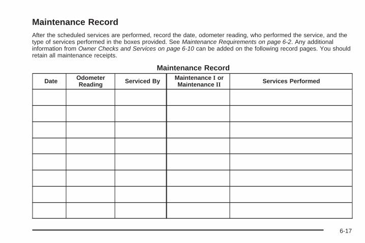
Maintenance RecordAfter the scheduled services are performed, record the date, odometer reading, who performed the service, and thetype of services performed in the boxes provided. See Maintenance Requirements on page 6-2. Any additionalinformation from Owner Checks and Services on page 6-10 can be added on the following record pages. You shouldretain all maintenance receipts.
Maintenance Record
Date OdometerReading Serviced By Maintenance I or
Maintenance II Services Performed
6-17

Maintenance Record (cont’d)
Date OdometerReading Serviced By Maintenance I or
Maintenance II Services Performed
6-18

Maintenance Record (cont’d)
Date OdometerReading Serviced By Maintenance I or
Maintenance II Services Performed
6-19

Maintenance Record (cont’d)
Date OdometerReading Serviced By Maintenance I or
Maintenance II Services Performed
6-20

Customer Assistance and Information ...............7-2Customer Satisfaction Procedure ......................7-2Online Owner Center ......................................7-5Customer Assistance for Text Telephone
(TTY) Users ...............................................7-6Customer Assistance Offices ............................7-6GM Mobility Reimbursement Program ................7-7Roadside Assistance Program ..........................7-7Scheduling Service Appointments ....................7-10Courtesy Transportation Program ....................7-10Collision Damage Repair ................................7-12
Reporting Safety Defects ................................7-15Reporting Safety Defects to the
United States Government ..........................7-15Reporting Safety Defects to the
Canadian Government ................................7-16Reporting Safety Defects to
General Motors .........................................7-16Service Publications Ordering Information .........7-16
Vehicle Data Recording and Privacy ................7-17Event Data Recorders ...................................7-18OnStar® ......................................................7-19Navigation System ........................................7-19Radio Frequency
Identification (RFID) ...................................7-19
Section 7 Customer Assistance Information
7-1

Customer Assistance andInformation
Customer Satisfaction ProcedureYour satisfaction and goodwill are important to yourdealer and to Pontiac. Normally, any concerns with thesales transaction or the operation of the vehicle will beresolved by the dealer’s sales or service departments.Sometimes, however, despite the best intentions of allconcerned, misunderstandings can occur. If your concernhas not been resolved to your satisfaction, the followingsteps should be taken:
STEP ONE: Discuss your concern with a member ofdealership management. Normally, concerns can bequickly resolved at that level. If the matter has alreadybeen reviewed with the sales, service, or parts manager,contact the owner of the dealership or the generalmanager.
STEP TWO: If after contacting a member of dealershipmanagement, it appears your concern cannot beresolved by the dealership without further help, in theU.S., call the Pontiac Customer Assistance Centerat 1-800-762-2737. In Canada, call General Motorsof Canada Customer Communication Centre at1-800-263-3777 (English) or 1-800-263-7854 (French).
We encourage you to call the toll-free number in order togive your inquiry prompt attention. Have the followinginformation available to give the Customer AssistanceRepresentative:
• Vehicle Identification Number (VIN). This is availablefrom the vehicle registration or title, or the plate at thetop left of the instrument panel and visible throughthe windshield.
• Dealership name and location.
• Vehicle delivery date and present mileage.
When contacting Pontiac, remember that your concernwill likely be resolved at a dealer’s facility. That is why wesuggest you follow Step One first.
7-2

STEP THREE — U.S. Owners: Both General Motorsand your dealer are committed to making sure you arecompletely satisfied with your new vehicle. However, ifyou continue to remain unsatisfied after following theprocedure outlined in Steps One and Two, you can filewith the BBB Auto Line Program to enforce your rights.
The BBB Auto Line Program is an out of court programadministered by the Council of Better Business Bureausto settle automotive disputes regarding vehicle repairs orthe interpretation of the New Vehicle Limited Warranty.Although you may be required to resort to this informaldispute resolution program prior to filing a court action,use of the program is free of charge and your case willgenerally be heard within 40 days. If you do not agreewith the decision given in your case, you may reject it andproceed with any other venue for relief available to you.
You can contact the BBB Auto Line Program using thetoll-free telephone number or write them at the followingaddress:
BBB Auto Line ProgramCouncil of Better Business Bureaus, Inc.4200 Wilson BoulevardSuite 800Arlington, VA 22203-1838
Telephone: 1-800-955-5100www.dr.bbb.org/goauto
This program is available in all 50 states and the Districtof Columbia. Eligibility is limited by vehicle age, mileageand other factors. General Motors reserves the right tochange eligibility limitations and/or discontinue itsparticipation in this program.
7-3

STEP THREE — Canadian Owners: In the event thatyou do not feel your concerns have been addressed afterfollowing the procedure outlined in Steps One and Two,General Motors of Canada Limited wants you to be awareof its participation in a no-charge Mediation/ArbitrationProgram. General Motors of Canada Limited hascommitted to binding arbitration of owner disputesinvolving factory-related vehicle service claims.The program provides for the review of the factsinvolved by an impartial third party arbiter, andmay include an informal hearing before the arbiter.The program is designed so that the entire disputesettlement process, from the time you file yourcomplaint to the final decision, should be completedin approximately 70 days. We believe our impartialprogram offers advantages over courts in mostjurisdictions because it is informal, quick, andfree of charge.
For further information concerning eligibility in theCanadian Motor Vehicle Arbitration Plan (CAMVAP), calltoll-free 1-800-207-0685, or call the General MotorsCustomer Communication Centre, 1-800-263-3777(English), 1-800-263-7854 (French), or write to:
Mediation/Arbitration Programc/o Customer Communication CentreGeneral Motors of Canada LimitedMail Code: CA1-163-0051908 Colonel Sam DriveOshawa, Ontario L1H 8P7
Your inquiry should be accompanied by the VehicleIdentification Number (VIN).
7-4

Online Owner Center
Online Owner Center (U.S.) —www.gmownercenter.com/pontiacInformation and services customized for your specificvehicle — all in one convenient place.
• Digital owner manual, warranty information,and more
• Online service and maintenance records
• Find Pontiac dealers for service nationwide
• Exclusive privileges and offers
• Recall notices for your specific vehicle
• OnStar® and GM Cardmember Services Earningssummaries
Other Helpful Links:Pontiac — www.pontiac.com
Pontiac Merchandise — www.pontiacmall.com
Help Center — www.pontiac.com/helpcenter
• FAQ
• Contact Us
My GM Canada (Canada) — www.gm.caMy GM Canada is a password-protected section ofwww.gm.ca where you can save information onGM vehicles, get personalized offers, and use handytools and forms with greater ease.
Here are a few of the valuable tools and services youwill have access to:
• My Showroom: Find and save information onvehicles and current offers in your area.
• My Dealers/Retailers: Save details such as addressand phone number for each of your preferred GMdealers/retailers.
• My Driveway: Access quick links to parts andservice estimates, check trade-in values, orschedule a service appointment by adding thevehicles you own to your driveway profile.
• My Preferences: Manage your profile and use toolsand forms with greater ease.
To sign up, visit the My GM Canada section withinwww.gm.ca.
7-5

Customer Assistance for TextTelephone (TTY) UsersTo assist customers who are deaf, hard of hearing, orspeech-impaired and who use Text Telephones (TTYs),Pontiac has TTY equipment available at its CustomerAssistance Center. Any TTY user in the U.S. cancommunicate with Pontiac by dialing: 1-800-833-PONT(7668). (TTY users in Canada can dial 1-800-263-3830.)
Customer Assistance OfficesPontiac encourages customers to call the toll-freenumber for assistance. However, if a customer wishes towrite or e-mail Pontiac, the letter should be addressed to:
United States — Customer AssistancePontiac Customer Assistance CenterP.O. Box 33172Detroit, MI 48232-5172
www.Pontiac.com1-800-762-2737 or1-800-833-7668 (For Text Telephone devices (TTYs))Roadside Assistance: 1-800-ROADSIDE (762-3743)
From Puerto Rico:1-800-496-9992 (English)1-800-496-9993 (Spanish)
From U.S. Virgin Islands:1-800-496-9994
Canada — Customer AssistanceGeneral Motors of Canada LimitedCustomer Communication Centre, CA1-163-0051908 Colonel Sam DriveOshawa, Ontario L1H 8P7
www.gmcanada.com1-800-263-3777 (English)1-800-263-7854 (French)1-800-263-3830 (For Text Telephone devices (TTYs))Roadside Assistance: 1-800-268-6800
Overseas — Customer AssistancePlease contact the local General Motors Business Unit.
Mexico, Central America and CaribbeanIslands/Countries (Except Puerto Ricoand U.S. Virgin Islands) — CustomerAssistance
General Motors de Mexico, S. de R.L. de C.V.Customer Assistance CenterPaseo de la Reforma #2740Col. Lomas de BezaresC.P. 11910, Mexico, D.F.01-800-508-0000Long Distance: 011-52-53 29 0 800
7-6

GM Mobility ReimbursementProgram
This program, available to qualified applicants, canreimburse you up to $1,000 of the cost of eligibleaftermarket adaptive equipment required for your vehicle,such as hand controls or a wheelchair/scooter lift.
The offer is available for a very limited period of timefrom the date of vehicle purchase/lease. For moredetails, or to determine your vehicle’s eligibility, visitgmmobility.com or call the GM Mobility AssistanceCenter at 1-800-323-9935. Text telephone (TTY) users,call 1-800-833-9935.
General Motors of Canada also has a Mobility Program.Call 1-800-GM-DRIVE (463-7483) for details. TTY userscall 1-800-263-3830.
Roadside Assistance ProgramFor U.S. purchased vehicles, call 1-800-ROADSIDE(762-3743); (Text telephone (TTY): 1-888-889-2438).
For Canadian purchased vehicles, call 1-800-268-6800.
Service is available 24 hours a day, 365 days a year.
Calling for AssistanceWhen calling Roadside Assistance, have the followinginformation ready:
• Your name, home address, and home telephonenumber
• Telephone number of your location
• Location of the vehicle
• Model, year, color, and license plate number of thevehicle
• Odometer reading, Vehicle Identification Number(VIN), and delivery date of the vehicle
• Description of the problem
7-7

CoverageServices are provided up to 5 years/100,000 miles(160 000 km), whichever comes first.
In the U.S., anyone driving the vehicle is covered.In Canada, a person driving the vehicle withoutpermission from the owner is not covered.
Roadside Assistance is not a part of the New VehicleLimited Warranty. Pontiac and General Motors ofCanada Limited reserve the right to make any changesor discontinue the Roadside Assistance program at anytime without notification.
Pontiac and General Motors of Canada Limited reservethe right to limit services or payment to an owner or driverif they decide the claims are made too often, or the sametype of claim is made many times.
Services Provided• Emergency Fuel Delivery: Delivery of enough fuel
for the vehicle to get to the nearest service station.
• Lock-Out Service: Service is provided to unlock thevehicle if you are locked out. A remote unlock may beavailable if you have OnStar®. For security reasons,the driver must present identification before thisservice is given.
• Emergency Tow From a Public Road or Highway:Tow to the nearest Pontiac dealer for warrantyservice, or if the vehicle was in a crash and cannotbe driven. Assistance is also given when the vehicleis stuck in sand, mud, or snow.
• Flat Tire Change: Service is provided to change aflat tire with the spare tire. The spare tire, if equipped,must be in good condition and properly inflated.It is the owner’s responsibility for the repair orreplacement of the tire if it is not covered by thewarranty.
• Battery Jump Start: Service is provided to jumpstart a dead battery.
• Trip Interruption Benefits and Assistance: If yourtrip is interrupted due to a warranty failure, incidentalexpenses may be reimbursed during the 5 years/100,000 miles (160 000 km) Powertrain warrantyperiod. Items considered are hotel, meals, andrental car.
7-8

Services Not Included in RoadsideAssistance• Impound towing caused by violation of any laws.
• Legal fines.
• Mounting, dismounting or changing of snow tires,chains, or other traction devices.
• Towing or services for vehicles driven on anon-public road or highway.
Services Specific to CanadianPurchased Vehicles• Fuel delivery: Reimbursement is approximately
$5 Canadian. Diesel fuel delivery may berestricted. Propane and other fuels are not providedthrough this service.
• Lock-Out Service: Vehicle registration is required.
• Trip Routing Service: Detailed maps of NorthAmerica are provided when requested either withthe most direct route or the most scenic route. Thereis a limit of six requests per year. Additional travelinformation is also available. Allow three weeks fordelivery.
• Trip Interruption Benefits and Assistance: Mustbe over 250 kilometres from where your trip wasstarted to qualify. General Motors of Canada Limitedrequires pre-authorization, original detailed receipts,and a copy of the repair orders. Once authorizationhas been received, the Roadside Assistance advisorwill help you make arrangements and explain how toreceive payment.
• Alternative Service: If assistance cannot beprovided right away, the Roadside Assistanceadvisor may give you permission to get localemergency road service. You will receive payment,up to $100, after sending the original receipt toRoadside Assistance. Mechanical failures may becovered, however any cost for parts and labor forrepairs not covered by the warranty are the ownerresponsibility.
7-9

Scheduling Service AppointmentsWhen your vehicle requires warranty service, contactyour dealer/retailer and request an appointment.By scheduling a service appointment and advising yourservice consultant of your transportation needs, yourdealer/retailer can help minimize your inconvenience.
If your vehicle cannot be scheduled into the servicedepartment immediately, keep driving it until it can bescheduled for service, unless, of course, the problem issafety-related. If it is, please call your dealership/retailer,let them know this, and ask for instructions.
If the dealer/retailer requests you to bring the vehicle forservice, you are urged to do so as early in the workday as possible to allow for the same day repair.
Courtesy Transportation ProgramTo enhance your ownership experience, we andour participating dealers are proud to offer CourtesyTransportation, a customer support program for vehicleswith the Bumper to Bumper (Base Warranty Coverageperiod in Canada) and extended powertrain, and hybridspecific warranty in both the U.S. and Canada.
Several courtesy transportation options are available toassist in reducing your inconvenience when warrantyrepairs are required.
Courtesy Transportation is not a part of the New VehicleLimited Warranty. A separate booklet entitled “Warrantyand Owner Assistance Information” furnished witheach new vehicle provides detailed warranty coverageinformation.
7-10
Transportation OptionsWarranty service can generally be completed while youwait. However, if you are unable to wait, GM helps tominimize your inconvenience by providing severaltransportation options. Depending on the circumstances,your dealer can offer you one of the following:
Shuttle ServiceShuttle service is the preferred means of offeringCourtesy Transportation. Dealers may provide you withshuttle service to get you to your destination with minimalinterruption of your daily schedule. This includes one-wayor round trip shuttle service within reasonable time anddistance parameters of the dealer’s area.
Public Transportation or FuelReimbursementIf your vehicle requires overnight warranty repairs, andpublic transportation is used instead of the dealer’sshuttle service, the expense must be supportedby original receipts and can only be up to the maximumamount allowed by GM for shuttle service. In addition,for U.S. customers, should you arrange transportationthrough a friend or relative, limited reimbursementfor reasonable fuel expenses may be available.
Claim amounts should reflect actual costs and besupported by original receipts. See your dealer forinformation regarding the allowance amounts forreimbursement of fuel or other transportation costs.
Courtesy Rental VehicleYour dealer may arrange to provide you with a courtesyrental vehicle or reimburse you for a rental vehicle thatyou obtain if your vehicle is kept for an overnight warrantyrepair. Rental reimbursement will be limited and mustbe supported by original receipts. This requires that yousign and complete a rental agreement and meet state/provincial, local, and rental vehicle provider requirements.Requirements vary and may include minimum agerequirements, insurance coverage, credit card, etc.You are responsible for fuel usage charges and mayalso be responsible for taxes, levies, usage fees,excessive mileage, or rental usage beyond thecompletion of the repair.
It may not be possible to provide a like-vehicle as acourtesy rental.
7-11

Additional Program InformationAll program options, such as shuttle service, may not beavailable at every dealer. Please contact your dealerfor specific information about availability. All CourtesyTransportation arrangements will be administeredby appropriate dealer personnel.
General Motors reserves the right to unilaterally modify,change or discontinue Courtesy Transportation atany time and to resolve all questions of claim eligibilitypursuant to the terms and conditions describedherein at its sole discretion.
Collision Damage RepairIf your vehicle is involved in a collision and it is damaged,have the damage repaired by a qualified technicianusing the proper equipment and quality replacementparts. Poorly performed collision repairs diminishyour vehicle’s resale value, and safety performancecan be compromised in subsequent collisions.
Collision PartsGenuine GM Collision parts are new parts made with thesame materials and construction methods as the partswith which your vehicle was originally built. Genuine GMCollision parts are your best choice to ensure that yourvehicle’s designed appearance, durability, and safetyare preserved. The use of Genuine GM parts can helpmaintain your GM New Vehicle Warranty.
Recycled original equipment parts may also be used forrepair. These parts are typically removed from vehiclesthat were total losses in prior crashes. In most cases, theparts being recycled are from undamaged sections of thevehicle. A recycled original equipment GM part, may bean acceptable choice to maintain your vehicle’s originallydesigned appearance and safety performance, however,the history of these parts is not known. Such parts are notcovered by your GM New Vehicle Limited Warranty, andany related failures are not covered by that warranty.
7-12

Aftermarket collision parts are also available. These aremade by companies other than GM and may not havebeen tested for your vehicle. As a result, these parts mayfit poorly, exhibit premature durability/corrosion problems,and may not perform properly in subsequent collisions.Aftermarket parts are not covered by your GM NewVehicle Limited Warranty, and any vehicle failure relatedto such parts are not covered by that warranty.
Repair FacilityWe recommend that you choose a collision repairfacility that meets your needs before you ever needcollision repairs. Your dealer/retailer may have acollision repair center with GM-trained technicians andstate of the art equipment, or be able to recommenda collision repair center that has GM-trained techniciansand comparable equipment.
Insuring Your VehicleProtect your investment in your GM vehicle withcomprehensive and collision insurance coverage.There are significant differences in the quality ofcoverage afforded by various insurance policy terms.Many insurance policies provide reduced protection toyour GM vehicle by limiting compensation for damagerepairs by using aftermarket collision parts. Someinsurance companies will not specify aftermarket collisionparts. When purchasing insurance, we recommend thatyou assure your vehicle will be repaired with GM originalequipment collision parts. If such insurance coverage isnot available from your current insurance carrier,consider switching to another insurance carrier.
If your vehicle is leased, the leasing company mayrequire you to have insurance that assures repairs withGenuine GM Original Equipment Manufacturer (OEM)parts or Genuine Manufacturer replacement parts. Readyour lease carefully, as you may be charged at theend of your lease for poor quality repairs.
7-13

If a Crash OccursHere is what to do if you are involved in a crash.
• Check to make sure that you are all right. If youare uninjured, make sure that no one else in yourvehicle, or the other vehicle, is injured.
• If there has been an injury, call emergency servicesfor help. Do not leave the scene of a crash until allmatters have been taken care of. Move your vehicleonly if its position puts you in danger or you areinstructed to move it by a police officer.
• Give only the necessary and requested informationto police and other parties involved in the crash.Do not discuss your personal condition, mental frameof mind, or anything unrelated to the crash. This willhelp guard against post-crash legal action.
• If you need roadside assistance, call GM RoadsideAssistance. See Roadside Assistance Program onpage 7-7 for more information.
• If your vehicle cannot be driven, know where thetowing service will be taking it. Get a card from thetow truck operator or write down the driver’s name,the service’s name, and the phone number.
• Remove any valuables from your vehicle before it istowed away. Make sure this includes your insuranceinformation and registration if you keep these itemsin your vehicle.
• Gather the important information you will need fromthe other driver. Things like name, address, phonenumber, driver’s license number, vehicle licenseplate, vehicle make, model and model year, VehicleIdentification Number (VIN), insurance company andpolicy number, and a general description of thedamage to the other vehicle.
• If possible, call your insurance company from thescene of the crash. They will walk you through theinformation they will need. If they ask for a policereport, phone or go to the police departmentheadquarters the next day and you can get a copy ofthe report for a nominal fee. In some states/provinceswith “no fault” insurance laws, a report may not benecessary. This is especially true if there are noinjuries and both vehicles are driveable.
• Choose a reputable collision repair facility for yourvehicle. Whether you select a dealer/retailer or aprivate collision repair facility to fix the damage,make sure you are comfortable with them.Remember, you will have to feel comfortablewith their work for a long time.
• Once you have an estimate, read it carefully andmake sure you understand what work will beperformed on your vehicle. If you have a question,ask for an explanation. Reputable shops welcomethis opportunity.
7-14

Managing the Vehicle Damage RepairProcessIn the event that your vehicle requires damage repairs,GM recommends that you take an active role in its repair.If you have a pre-determined repair facility of choice, takeyour vehicle there, or have it towed there. Specify to thefacility that any required replacement collision parts beoriginal equipment parts, either new Genuine GM partsor recycled original GM parts. Remember, recycledparts will not be covered by your GM vehicle warranty.
Insurance pays the bill for the repair, but you mustlive with the repair. Depending on your policy limits,your insurance company may initially value the repairusing aftermarket parts. Discuss this with your repairprofessional, and insist on Genuine GM parts. Rememberif your vehicle is leased you may be obligated to have thevehicle repaired with Genuine GM parts, even if yourinsurance coverage does not pay the full cost.
If another party’s insurance company is paying for therepairs, you are not obligated to accept a repair valuationbased on that insurance company’s collision policyrepair limits, as you have no contractual limits with thatcompany. In such cases, you can have control of therepair and parts choices as long as cost stays withinreasonable limits.
Reporting Safety Defects
Reporting Safety Defects to theUnited States GovernmentIf you believe that your vehicle has a defect whichcould cause a crash or could cause injury or death,you should immediately inform the NationalHighway Traffic Safety Administration (NHTSA)in addition to notifying General Motors.
If NHTSA receives similar complaints, it may openan investigation, and if it finds that a safety defectexists in a group of vehicles, it may order a recalland remedy campaign. However, NHTSA cannotbecome involved in individual problems betweenyou, your dealer/retailer, or General Motors.
To contact NHTSA, you may call the VehicleSafety Hotline toll-free at 1-888-327-4236(TTY: 1-800-424-9153); go to safercar.gov; orwrite to:
Administrator, NHTSA1200 New Jersey Avenue, S.E.Washington D.C., 20590
You can also obtain other information about motorvehicle safety from safercar.gov.
7-15

Reporting Safety Defects to theCanadian GovernmentIf you live in Canada, and you believe that yourvehicle has a safety defect, notify Transport Canadaimmediately, in addition to notifying General Motors ofCanada Limited. Call them at 1-800-333-0510 orwrite to:
Transport CanadaRoad Safety Branch2780 Sheffield RoadOttawa, Ontario K1B 3V9
Reporting Safety Defects toGeneral MotorsIn addition to notifying NHTSA (or Transport Canada) ina situation like this, please notify General Motors.
Call 1-800-762-2737, or write:
Pontiac Customer Assistance CenterP.O. Box 33172Detroit, MI 48232-5172
In Canada, call 1-800-263-3777 (English) or1-800-263-7854 (French), or write:
General Motors of Canada LimitedCustomer Communication Centre, CA1-163-0051908 Colonel Sam DriveOshawa, Ontario L1H 8P7
Service Publications OrderingInformation
Service ManualsService Manuals have the diagnosis and repairinformation on engines, transmission, axle suspension,brakes, electrical, steering, body, etc.
Service BulletinsService Bulletins give additional technical serviceinformation needed to knowledgeably serviceGeneral Motors cars and trucks. Each bulletincontains instructions to assist in the diagnosisand service of your vehicle.
Owner InformationOwner publications are written specifically for ownersand intended to provide basic operational informationabout the vehicle. The owner manual includes theMaintenance Schedule for all models.
In-Portfolio: Includes a Portfolio, Owner Manual, andWarranty Booklet.
RETAIL SELL PRICE: $35.00 (U.S.) plus processing fee
Without Portfolio: Owner Manual only.
RETAIL SELL PRICE: $25.00 (U.S.) plus processing fee
7-16

Current and Past Model Order FormsTechnical Service Bulletins and Manuals are availablefor current and past model GM vehicles. To requestan order form, specify year and model name ofthe vehicle.
ORDER TOLL FREE: 1-800-551-4123Monday-Friday 8:00 AM - 6:00 PMEastern TimeFor Credit Card Orders Only(VISA-MasterCard-Discover), visit Helm, Inc.on the World Wide Web at: helminc.com
Or you can write to:
Helm, IncorporatedP.O. Box 07130Detroit, MI 48207
Prices are subject to change without notice and withoutincurring obligation. Allow ample time for delivery.
Note to Canadian Customers: All listed prices arequoted in U.S. funds. Canadian residents are to makechecks payable in U.S. funds.
Vehicle Data Recording andPrivacyYour GM vehicle has a number of sophisticatedcomputers that record information about the vehicle’sperformance and how it is driven. For example, yourvehicle uses computer modules to monitor and controlengine and transmission performance, to monitor theconditions for airbag deployment and deploy airbags in acrash and, if so equipped, to provide antilock braking tohelp the driver control the vehicle. These modules maystore data to help your dealer/retailer technician serviceyour vehicle. Some modules may also store data abouthow you operate the vehicle, such as rate of fuelconsumption or average speed. These modules mayalso retain the owner’s personal preferences, such asradio pre-sets, seat positions, and temperature settings.
7-17

Event Data RecordersThis vehicle has an Event Data Recorder (EDR).The main purpose of an EDR is to record, in certaincrash or near crash-like situations, such as an airbagdeployment or hitting a road obstacle, data that will assistin understanding how a vehicle’s systems performed.The EDR is designed to record data related to vehicledynamics and safety systems for a short period of time,typically 30 seconds or less. The EDR in this vehicle isdesigned to record such data as:
• How various systems in your vehicle were operating
• Whether or not the driver and passenger safety beltswere buckled/fastened
• How far, if at all, the driver was pressing theaccelerator and/or brake pedal
• How fast the vehicle was traveling
This data can help provide a better understanding of thecircumstances in which crashes and injuries occur.
Important: EDR data is recorded by your vehicle onlyif a non-trivial crash situation occurs; no data is recordedby the EDR under normal driving conditions and nopersonal data (e.g., name, gender, age, and crashlocation) is recorded. However, other parties, such aslaw enforcement, could combine the EDR data with thetype of personally identifying data routinely acquiredduring a crash investigation.
To read data recorded by an EDR, special equipmentis required, and access to the vehicle or the EDR isneeded. In addition to the vehicle manufacturer, otherparties, such as law enforcement, that have the specialequipment, can read the information if they have accessto the vehicle or the EDR.
GM will not access this data or share it with othersexcept: with the consent of the vehicle owner or, if thevehicle is leased, with the consent of the lessee; inresponse to an official request of police or similargovernment office; as part of GM’s defense of litigationthrough the discovery process; or, as required by law.Data that GM collects or receives may also be used forGM research needs or may be made available to othersfor research purposes, where a need is shown and thedata is not tied to a specific vehicle or vehicle owner.
7-18
OnStar®
If your vehicle has OnStar and you subscribe to theOnStar services, please refer to the OnStar Terms andConditions for information on data collection and use.See also OnStar® System on page 2-38 in this manual formore information.
Navigation SystemIf your vehicle has a navigation system, use of thesystem may result in the storage of destinations,addresses, telephone numbers, and other tripinformation. Refer to the navigation system operatingmanual for information on stored data and for deletioninstructions.
Radio FrequencyIdentification (RFID)RFID technology is used in some vehicles forfunctions such as tire pressure monitoring andignition system security, as well as in connectionwith conveniences such as key fobs for remotedoor locking/unlocking and starting, and in-vehicletransmitters for garage door openers. RFID technologyin GM vehicles does not use or record personalinformation or link with any other GM system containingpersonal information.
7-19

✍ NOTES
7-20

AAccessories and Modifications ............................ 5-3Accessory Power ............................................ 2-21Accessory Power Outlets ................................. 3-18Adding Equipment to Your
Airbag-Equipped Vehicle ............................... 1-68Additional Required Services,
Scheduled Maintenance ................................. 6-7Additives, Fuel ................................................. 5-6Add-On Electrical Equipment ............................ 5-91Adjustments
Headlamp Range .......................................... 1-7Air Cleaner/Filter, Engine ................................. 5-20Air Conditioning .............................................. 3-19Air Filter, Passenger Compartment .................... 3-23Airbag
Readiness Light .......................................... 3-28Airbag System ................................................ 1-55
Adding Equipment to YourAirbag-Equipped Vehicle ............................ 1-68
How Does an Airbag Restrain? ...................... 1-61Passenger Sensing System ........................... 1-63Servicing Your Airbag-Equipped Vehicle .......... 1-68What Makes an Airbag Inflate? ...................... 1-61What Will You See After an Airbag Inflates? ..... 1-62When Should an Airbag Inflate? .................... 1-60Where Are the Airbags? ............................... 1-58
AirbagsPassenger Status Indicator ........................... 3-29
All-Wheel Drive ............................................... 5-41All-Wheel Drive Disabled Light .......................... 3-39All-Wheel-Drive (AWD) System ........................... 4-8All-Wheel-Drive Service Light ............................ 3-39Antilock Brake System (ABS) ............................. 4-5
Warning Light ............................................. 3-31Appearance Care
Aluminum or Chrome-Plated Wheels .............. 5-88Care of Safety Belts .................................... 5-85Chemical Paint Spotting ............................... 5-89Cleaning Exterior Lamps/Lenses .................... 5-86Fabric/Carpet .............................................. 5-83Finish Care ................................................. 5-87Finish Damage ............................................ 5-89Instrument Panel, Vinyl, and Other
Plastic Surfaces ....................................... 5-85Interior Cleaning .......................................... 5-82Leather ...................................................... 5-84Sheet Metal Damage ................................... 5-89Tires .......................................................... 5-88Underbody Maintenance ............................... 5-89Washing Your Vehicle ................................... 5-86Weatherstrips .............................................. 5-85Windshield and Wiper Blades ........................ 5-87
Ashtray ......................................................... 3-18Assistance Program, Roadside ........................... 7-7
1

Audio System ................................................. 3-64Audio Steering Wheel Controls .................... 3-118Navigation/Radio System,
see Navigation Manual .............................. 3-98Setting the Clock ......................................... 3-65
Audio System(s) ............................................. 3-67Audio Systems
Radio Reception ........................................ 3-119Theft-Deterrent Feature ............................... 3-118
Automatic Headlamp System ............................ 3-14Automatic Transmission
Fluid .......................................................... 5-22Operation ........................................... 2-24, 2-27
BBattery .......................................................... 5-35
Electric Power Management .......................... 3-16Run-Down Protection ................................... 3-17
Belt Routing, Engine ....................................... 6-16Bluetooth® ..................................................... 3-98Brake
Emergencies ................................................ 4-5Brake Fluid .................................................... 5-32Brakes .......................................................... 5-32
Antilock ....................................................... 4-5Parking ...................................................... 2-31System Warning Light .................................. 3-30
Braking ........................................................... 4-4Braking in Emergencies ..................................... 4-5Break-In, New Vehicle ..................................... 2-19Bulb Replacement ........................................... 5-46
Fog Lamp .................................................. 3-14Halogen Bulbs ............................................ 5-43Headlamp Aiming ........................................ 5-43Headlamps ................................................. 5-43Headlamps, Front Turn Signal, Sidemarker,
and Parking Lamps .................................. 5-44License Plate Lamps .................................... 5-46Taillamps, Turn Signal, Stoplamps and
Back-up Lamps ........................................ 5-45Buying New Tires ........................................... 5-64
CCalibration ..................................................... 3-47California
Perchlorate Materials Requirements ................. 5-4California Fuel .................................................. 5-6California Proposition 65 Warning ....................... 5-4Canadian Owners ................................................ iiCapacities and Specifications ............................ 5-97Carbon Monoxide
Engine Exhaust ........................................... 2-35Liftgate ...................................................... 2-12Winter Driving ............................................. 4-17
2

Care ofSafety Belts ................................................ 5-85
CargoLamp ......................................................... 3-16
CD, MP3 ............................................... 3-87, 3-92Center Console Storage ................................... 2-42Chains, Tire ................................................... 5-69Charging System Light .................................... 3-30Check
Engine Lamp .............................................. 3-34Checking Things Under the Hood ...................... 5-10Chemical Paint Spotting ................................... 5-89Child Restraints
Infants and Young Children ........................... 1-34Lower Anchors and Tethers for Children .......... 1-42Older Children ............................................. 1-31Securing a Child Restraint in a
Rear Seat Position ................................... 1-49Securing a Child Restraint in the
Right Front Seat Position .......................... 1-52Systems ..................................................... 1-37Where to Put the Restraint ........................... 1-40
Cigarette Lighter ............................................. 3-18Circuit Breakers .............................................. 5-91Cleaning
Aluminum or Chrome-Plated Wheels .............. 5-88Exterior Lamps/Lenses ................................. 5-86Fabric/Carpet .............................................. 5-83Finish Care ................................................. 5-87
Cleaning (cont.)Instrument Panel, Vinyl, and Other
Plastic Surfaces ....................................... 5-85Interior ....................................................... 5-82Leather ...................................................... 5-84Tires .......................................................... 5-88Underbody Maintenance ............................... 5-89Washing Your Vehicle ................................... 5-86Weatherstrips .............................................. 5-85Windshield and Wiper Blades ........................ 5-87
Climate Control System ................................... 3-19Outlet Adjustment ........................................ 3-23
Clock, Setting ................................................. 3-65Collision Damage Repair .................................. 7-12Compact Spare Tire ........................................ 5-81Compass ....................................................... 3-47Content Theft-Deterrent .................................... 2-17Control of a Vehicle .......................................... 4-3Convenience Net ............................................ 2-47Coolant
Engine ....................................................... 5-23Engine Temperature Gage ............................ 3-33Engine Temperature Warning Light ................. 3-32
Cooling System .............................................. 5-22Courtesy Transportation Program ...................... 7-10Cruise Control ................................................ 3-10Cruise Control Light ........................................ 3-38Cupholders .................................................... 2-42
3

Customer Assistance ......................................... 7-6Offices ......................................................... 7-6Text Telephone (TTY) Users ........................... 7-6
Customer InformationService Publications Ordering Information ........ 7-16
Customer Satisfaction Procedure ........................ 7-2
DDamage Repair, Collision ................................. 7-12Data Recorders
Event ......................................................... 7-18Daytime Running Lamps (DRL) ......................... 3-13Defensive Driving ............................................. 4-2Delayed Locking ............................................. 2-10DIC Compass ................................................. 3-47Disc, MP3 ............................................. 3-87, 3-92Doing Your Own Service Work ........................... 5-4Dome Lamp ................................................... 3-15Door
Ajar Light ................................................... 3-40Delayed Locking .......................................... 2-10Locks ........................................................ 2-10Power Door Locks ....................................... 2-10Programmable Automatic Door Locks ............. 2-11Rear Door Security Locks ............................. 2-11
Drive SystemsAll-Wheel Drive ........................................... 5-41
DriverSeat Height Adjuster ...................................... 1-3
Driver Information Center (DIC) ......................... 3-42DIC Operation and Displays .......................... 3-42DIC Vehicle Personalization .......................... 3-57DIC Warnings and Messages ........................ 3-49
DrivingAt Night ..................................................... 4-13Before a Long Trip ...................................... 4-15Defensive ..................................................... 4-2Drunk .......................................................... 4-3Highway Hypnosis ....................................... 4-15Hill and Mountain Roads .............................. 4-16In Rain and on Wet Roads ........................... 4-14Loss of Control ........................................... 4-12Off-Road Recovery ...................................... 4-11Rocking Your Vehicle to Get it Out ................. 4-20Winter ........................................................ 4-17
Driving for Better Fuel Economy ......................... 4-2DVD
Rear Seat Entertainment System .................. 3-109
4

EEDR ............................................................. 7-17Electrical Equipment
Add-On Equipment ...................................... 5-91Electrical System
Engine Compartment Fuse Block ................... 5-93Fuses and Circuit Breakers ........................... 5-91Instrument Panel Fuse Block ......................... 5-92Windshield Wiper Fuses ............................... 5-91
Electronic ImmobilizerPASS-Key® III+ ........................................... 2-17
Electronic Immobilizer OperationPASS-Key® III+ ........................................... 2-18
EngineAir Cleaner/Filter ......................................... 5-20Change Engine Oil Light ............................... 3-37Check and Service Engine Soon Lamp ........... 3-34Compartment Overview ................................ 5-12Coolant ...................................................... 5-23Coolant Heater ............................................ 2-23Coolant Temperature Gage ........................... 3-33Coolant Temperature Warning Light ................ 3-32Cooling System ........................................... 5-22Drive Belt Routing ....................................... 6-16Exhaust ..................................................... 2-35Oil ............................................................. 5-15Oil Life System ........................................... 5-18
Engine (cont.)Overheated Protection Operating Mode ........... 5-29Overheating ................................................ 5-28Reduced Power Light ................................... 3-38Starting ...................................................... 2-22
Entry Lighting ................................................. 3-15Event Data Recorders ..................................... 7-18Extender, Safety Belt ....................................... 1-30
FFilter
Engine Air Cleaner ...................................... 5-20Finish Damage ............................................... 5-89Flashers, Hazard Warning .................................. 3-6Flash-to-Pass ................................................... 3-8Flat Tire ........................................................ 5-70Flat Tire, Changing ......................................... 5-70Flat Tire, Storing ............................................. 5-79Fluid
Automatic Transmission ................................ 5-22Power Steering ........................................... 5-30Windshield Washer ...................................... 5-31
Fog LampFog ........................................................... 3-14
Fog Lamp Light .............................................. 3-37Folding Rear Seat ........................................... 1-10Folding Seatback, Passenger ............................. 1-8
5

Fuel ............................................................... 5-5Additives ...................................................... 5-6California Fuel .............................................. 5-6Economy Driving ........................................... 4-2Filling a Portable Fuel Container .................... 5-10Filling the Tank ............................................. 5-8Fuels in Foreign Countries .............................. 5-7Gage ......................................................... 3-41Gasoline Octane ........................................... 5-5Gasoline Specifications .................................. 5-6Low Fuel Warning Light ................................ 3-41
FusesEngine Compartment Fuse Block ................... 5-93Fuses and Circuit Breakers ........................... 5-91Instrument Panel Fuse Block ......................... 5-92Windshield Wiper ......................................... 5-91
GGage
Speedometer .............................................. 3-26Tachometer ................................................. 3-26
GagesEngine Coolant Temperature ......................... 3-33Fuel .......................................................... 3-41Trip Odometer ............................................. 3-26
GasolineOctane ........................................................ 5-5Specifications ............................................... 5-6
Gate Ajar Light ............................................... 3-40Glove Box ..................................................... 2-42GM Mobility Reimbursement Program .................. 7-7
HHalogen Bulbs ................................................ 5-43Hazard Warning Flashers ................................... 3-6Head Restraints ............................................... 1-7Headlamp
Aiming ....................................................... 5-43Headlamps .................................................... 3-13
Bulb Replacement ....................................... 5-43Daytime Running Lamps (DRL) ..................... 3-13Flash-to-Pass ............................................... 3-8Headlamps, Front Turn Signal, Sidemarker,
and Parking Lamps .................................. 5-44High/Low Beam Changer ................................ 3-8On Reminder .............................................. 3-13Range Adjustment ......................................... 1-7
Heated Seats ................................................... 1-4Heater ........................................................... 3-19
Engine Coolant ........................................... 2-23
6

Height Adjuster, Driver Seat ............................... 1-3Highbeam On Light ......................................... 3-38High-Speed Operation, Tires ............................. 5-56Highway Hypnosis ........................................... 4-15Hill and Mountain Roads .................................. 4-16Hood
Checking Things Under ................................ 5-10Release ..................................................... 5-11
Horn ............................................................... 3-6How to Wear Safety Belts Properly ................... 1-17
IIgnition Positions ............................................. 2-20Infants and Young Children, Restraints ............... 1-34Inflation - Tire Pressure ................................... 5-55Instrument Panel
Brightness .................................................. 3-15Cluster ....................................................... 3-25Overview ..................................................... 3-4
Introduction ...................................................... 6-2
JJump Starting ................................................. 5-36
KKeyless Entry, Remote Operation ........................ 2-5Keyless Entry System ....................................... 2-4Keys ............................................................... 2-3
LLabeling, Tire Sidewall ..................................... 5-49Lamp
Malfunction Indicator .................................... 3-34Lamps
Cargo ........................................................ 3-16Daytime Running (DRL) ................................ 3-13Dome ........................................................ 3-15License Plate .............................................. 5-46Map .......................................................... 3-16
Lap-Shoulder Belt ........................................... 1-25LATCH System for Child Restraints ................... 1-42Liftgate
Carbon Monoxide ........................................ 2-12Lighting
Entry ......................................................... 3-15
7

Lights ............................................................ 3-13Airbag Readiness ........................................ 3-28All-Wheel Drive Disabled .............................. 3-39Antilock Brake System (ABS) Warning ............ 3-31Brake System Warning ................................. 3-30Change Engine Oil ...................................... 3-37Charging System ......................................... 3-30Cruise Control ............................................. 3-38Door Ajar ................................................... 3-40Engine Coolant Temperature Warning ............. 3-32Flash-to-Pass ............................................... 3-8Fog Lamp .................................................. 3-37Gate Ajar ................................................... 3-40Highbeam On ............................................. 3-38High/Low Beam Changer ................................ 3-8Low Fuel Warning ....................................... 3-41Oil Pressure ............................................... 3-36On Reminder .............................................. 3-13Passenger Airbag Status Indicator .................. 3-29Reduced Engine Power ................................ 3-38Safety Belt Reminders .................................. 3-27Security ..................................................... 3-37Service All-Wheel-Drive ................................ 3-39Service Vehicle Soon ................................... 3-40Tire Pressure .............................................. 3-33Traction Control System (TCS) Warning .......... 3-32
Loading Your Vehicle ....................................... 4-20
LocksDelayed Locking .......................................... 2-10Door .......................................................... 2-10Lockout Protection ....................................... 2-12Power Door ................................................ 2-10Programmable Automatic Door Locks ............. 2-11Rear Door Security Locks ............................. 2-11
Loss of Control ............................................... 4-12Low Fuel Warning Light ................................... 3-41Lower Anchors and Tethers for Children ............. 1-42Luggage Carrier .............................................. 2-42Lumbar
Manual Controls ............................................ 1-4
MMaintenance
Footnotes ..................................................... 6-8Maintenance Schedule
Additional Required Services ........................... 6-7At Each Fuel Fill ......................................... 6-10At Least Once a Month ................................ 6-11At Least Once a Year .................................. 6-11Maintenance Record .................................... 6-17Maintenance Replacement Parts .................... 6-15Maintenance Requirements ............................. 6-2Owner Checks and Services ......................... 6-10
8

Maintenance Schedule (cont.)Recommended Fluids and Lubricants ............. 6-13Scheduled Maintenance ................................. 6-4Using .......................................................... 6-2Your Vehicle and the Environment ................... 6-2
Malfunction Indicator Lamp ............................... 3-34Manual Lumbar Controls .................................... 1-4Manual Reclining Seatbacks ............................... 1-5Manual Seats ................................................... 1-2Map Lamps .................................................... 3-16Message
DIC Warnings and Messages ........................ 3-49Mirrors
Automatic Dimming Rearview ........................ 2-37Manual Rearview Mirror ................................ 2-36Outside Convex Mirrors ................................ 2-38Outside Power Mirrors .................................. 2-37
MP3 ..................................................... 3-87, 3-92
NNavigation System, Privacy .............................. 7-19Navigation/Radio System,
see Navigation Manual ................................. 3-98Net
Convenience ............................................... 2-47New Vehicle Break-In ...................................... 2-19
OOdometer ...................................................... 3-26Odometer, Trip ............................................... 3-26Off-Road
Recovery .................................................... 4-11Oil
Change Engine Oil Light ............................... 3-37Engine ....................................................... 5-15Engine Oil Life System ................................. 5-18Pressure Light ............................................. 3-36
Older Children, Restraints ................................ 1-31Online Owner Center ........................................ 7-5OnStar, Privacy .............................................. 7-19OnStar® System, see OnStar® Manual ............... 2-38Outlet Adjustment ............................................ 3-23Outlets
Accessory Power ......................................... 3-18Outside
Convex Mirrors ............................................ 2-38Power Mirrors ............................................. 2-37
Overheated Engine Protection Operating Mode .... 5-29Owner Checks and Services ............................. 6-10Owners, Canadian ............................................... ii
9

PPaint, Damage ............................................... 5-89Park
Shifting Into ................................................ 2-32Shifting Out of ............................................ 2-33
ParkingOver Things That Burn ................................. 2-34
Parking Brake ................................................ 2-31Passenger Airbag Status Indicator ..................... 3-29Passenger Compartment Air Filter ..................... 3-23Passenger Sensing System .............................. 1-63Passing ......................................................... 4-12PASS-Key® III+ Electronic Immobilizer ............... 2-17PASS-Key® III+ Electronic Immobilizer
Operation ................................................... 2-18Perchlorate Materials Requirements, California ...... 5-4Phone
Bluetooth® .................................................. 3-98Power
Door Locks ................................................. 2-10Reduced Engine Light .................................. 3-38Retained Accessory (RAP) ............................ 2-21Seat ............................................................ 1-3Steering Fluid ............................................. 5-30Windows .................................................... 2-15
Pregnancy, Using Safety Belts .......................... 1-30
Privacy .......................................................... 7-17Navigation System ....................................... 7-19OnStar ....................................................... 7-19Radio Frequency Identification (RFID) ............. 7-19
ProgramCourtesy Transportation ................................ 7-10
Programmable Automatic Door Locks ................. 2-11Proposition 65 Warning, California ....................... 5-4
RRadio Frequency Identification (RFID), Privacy .... 7-19Radio(s) ........................................................ 3-67Radios
Navigation/Radio System, see NavigationManual ................................................... 3-98
Reception ................................................. 3-119Setting the Clock ......................................... 3-65Theft-Deterrent .......................................... 3-118
Range Adjustment, Headlamps ........................... 1-7Rear Compartment Storage Panel/Cover ............ 2-44Rear Door Security Locks ................................ 2-11Rear Seat Armrest .......................................... 2-45Rear Seat Entertainment System ..................... 3-109Rear Window Washer/Wiper ............................. 3-10Rearview Mirror, Automatic Dimming .................. 2-37
10

Rearview Mirrors ............................................. 2-36Reclining Seatbacks, Manual .............................. 1-5Recommended Fluids and Lubricants ................. 6-13Recreational Vehicle Towing ............................. 4-26Reduced Engine Power Light ............................ 3-38Reimbursement Program, GM Mobility ................. 7-7Remote Keyless Entry (RKE) System .................. 2-4Remote Keyless Entry (RKE) System, Operation ... 2-5Remote Vehicle Start ........................................ 2-7Removing the Flat Tire and Installing the
Spare Tire .................................................. 5-73Removing the Spare Tire and Tools ................... 5-72Replacement Bulbs ......................................... 5-46Replacement Parts, Maintenance ...................... 6-15Reporting Safety Defects to General Motors ....... 7-16Reporting Safety Defects to the
Canadian Government .................................. 7-16Reporting Safety Defects to the
U.S. Government ......................................... 7-15Restraint System Check
Checking the Restraint Systems .................... 1-70Replacing Restraint System Parts
After a Crash .......................................... 1-71Retained Accessory Power (RAP) ...................... 2-21Roadside Assistance Program ............................ 7-7Rocking Your Vehicle to Get it Out .................... 4-20Roof
Sunroof ...................................................... 2-47Running the Vehicle While Parked ..................... 2-36
SSafety Belt Reminders ..................................... 3-27Safety Belts
Care of ...................................................... 5-85Extender .................................................... 1-30How to Wear Safety Belts Properly ................ 1-17Lap-Shoulder Belt ........................................ 1-25Safety Belts Are for Everyone ....................... 1-12Use During Pregnancy ................................. 1-30
Safety DefectsReporting to Canadian Government ................ 7-16Reporting to General Motors ......................... 7-16Reporting to the U.S. Government ................. 7-15
Safety Warnings and Symbols .............................. iiiScheduled Maintenance ..................................... 6-4
Additional Required Services ........................... 6-7Scheduling Appointments ................................. 7-10Seatback, Folding Passenger ............................. 1-8Seats
Driver Seat Height Adjuster ............................. 1-3Heated Seats ............................................... 1-4Manual Lumbar ............................................. 1-4Manual Reclining Seatbacks ........................... 1-5Passenger Folding Seatback ........................... 1-8Power Seat .................................................. 1-3Split Folding Rear Seat ................................ 1-10
Securing a Child RestraintRear Seat Position ...................................... 1-49Right Front Seat Position .............................. 1-52
11

Security Light ................................................. 3-37Service ........................................................... 5-3
Accessories and Modifications ......................... 5-3Adding Equipment to the Outside of the
Vehicle ..................................................... 5-5All-Wheel-Drive Light .................................... 3-39Doing Your Own Work ................................... 5-4Engine Soon Lamp ...................................... 3-34Publications Ordering Information ................... 7-16Scheduling Appointments .............................. 7-10Vehicle Soon Light ....................................... 3-40
Service Parts Identification Label ....................... 5-90Servicing Your Airbag-Equipped Vehicle .............. 1-68Setting the Clock ............................................ 3-65Sheet Metal Damage ....................................... 5-89Shifting
Out of Park ................................................ 2-33Shifting Into Park ............................................ 2-32Signals, Turn and Lane-Change .......................... 3-7Spare Tire
Compact .................................................... 5-81Installing .................................................... 5-73Removing ................................................... 5-72Storing ....................................................... 5-79
Specifications and Capacities ............................ 5-97Speedometer .................................................. 3-26Split Folding Rear Seat .................................... 1-10StabiliTrak® System .......................................... 4-6Start Vehicle, Remote ....................................... 2-7Starting the Engine ......................................... 2-22
Steering .......................................................... 4-9Steering Wheel Controls, Audio ....................... 3-118Steering Wheel, Tilt Wheel ................................. 3-6Storage Areas
Center Console ........................................... 2-42Convenience Net ......................................... 2-47Cupholders ................................................. 2-42Glove Box .................................................. 2-42Luggage Carrier .......................................... 2-42Rear Compartment Storage Panel/Cover ......... 2-44Rear Seat Armrest ....................................... 2-45Table ......................................................... 2-46
Stuck in Sand, Mud, Ice, or Snow ..................... 4-19Sun Visors ..................................................... 2-16Sunroof ......................................................... 2-47
TTable ............................................................ 2-46Tachometer .................................................... 3-26Taillamps
Turn Signal, Stoplamps and Back-up Lamps .... 5-45Text Telephone (TTY) Users ............................... 7-6Theft-Deterrent Feature .................................. 3-118Theft-Deterrent Systems ................................... 2-16
Content Theft-Deterrent ................................ 2-17PASS-Key® III+ Electronic Immobilizer ............ 2-17PASS-Key® III+ Electronic Immobilizer
Operation ................................................ 2-18
12

Tilt Wheel ........................................................ 3-6Time, Setting .................................................. 3-65Tire
Pressure Light ............................................. 3-33Tires ............................................................. 5-48
Aluminum or Chrome-Plated Wheels,Cleaning ................................................. 5-88
Buying New Tires ........................................ 5-64Chains ....................................................... 5-69Changing a Flat Tire .................................... 5-70Cleaning .................................................... 5-88Compact Spare ........................................... 5-81Different Size .............................................. 5-66High-Speed Operation .................................. 5-56If a Tire Goes Flat ....................................... 5-70Inflation - Tire Pressure ................................ 5-55Inspection and Rotation ................................ 5-62Installing the Spare Tire ................................ 5-73Pressure Monitor Operation ........................... 5-59Pressure Monitor System .............................. 5-57Removing the Flat Tire ................................. 5-73Removing the Spare Tire and Tools ............... 5-72Sidewall Labeling ......................................... 5-49Storing a Flat or Spare Tire and Tools ............ 5-79Terminology and Definitions ........................... 5-52
Tires (cont.)Uniform Tire Quality Grading ......................... 5-66Wheel Alignment and Tire Balance ................. 5-68Wheel Replacement ..................................... 5-68When It Is Time for New Tires ...................... 5-63
TowingRecreational Vehicle ..................................... 4-26Towing a Trailer .......................................... 4-33Your Vehicle ............................................... 4-26
TractionControl System (TCS) .................................... 4-7Control System Warning Light ....................... 3-32StabiliTrak® System ....................................... 4-6
TransmissionFluid, Automatic ........................................... 5-22
Transmission Operation, Automatic ............ 2-24, 2-27Transportation Program, Courtesy ...................... 7-10Trip Odometer ................................................ 3-26Turn and Lane-Change Signals .......................... 3-7Turn Signal/Multifunction Lever ........................... 3-7
UUniform Tire Quality Grading ............................ 5-66
13

VVehicle
Control ........................................................ 4-3Loading ...................................................... 4-20Running While Parked .................................. 2-36Service Soon Light ...................................... 3-40Symbols ......................................................... iii
Vehicle Data Recording and Privacy .................. 7-17Vehicle Data Recording,
Radio Frequency (RFID) ............................... 7-19Vehicle Identification
Number (VIN) ............................................. 5-90Service Parts Identification Label ................... 5-90
Vehicle PersonalizationDIC ........................................................... 3-57
Vehicle, Remote Start ....................................... 2-7Ventilation Adjustment ...................................... 3-23Visors ........................................................... 2-16
WWarning Lights, Gages, and Indicators ............... 3-24Warnings
DIC Warnings and Messages ........................ 3-49Hazard Warning Flashers ............................... 3-6Safety and Symbols ......................................... iii
WheelsAlignment and Tire Balance .......................... 5-68Different Size .............................................. 5-66Replacement ............................................... 5-68
When It Is Time for New Tires .......................... 5-63Where to Put the Child Restraint ....................... 1-40Windows ....................................................... 2-14
Power ........................................................ 2-15Windshield
Washer ........................................................ 3-9Washer Fluid .............................................. 5-31Wiper Blade Replacement ............................. 5-47Wiper Blades, Cleaning ................................ 5-87Wiper Fuses ............................................... 5-91Wipers ......................................................... 3-8
Winter Driving ................................................ 4-17Wipers
Rear Washer .............................................. 3-10
XXM Radio Messages ....................................... 3-97
YYour Vehicle and the Environment ....................... 6-2
14