2009 murano; abs / vdc light on with dtc c1161 / c1162 · xxxxxxxxxxxxx xxxxxx xxxxxxxxx...
TRANSCRIPT

1/17
Classification: Reference: Date:
BR10-009a NTB10-113a September 10, 2018
2009 MURANO; ABS / VDC LIGHT ON WITH DTC C1161 / C1162
This bulletin has been amended. The Service Procedure has been updated. No other changes have been made. Please discard previous versions of this bulletin.
APPLIED VEHICLE: 2009 Murano (Z51) with AWD only
APPLIED VIN: Vehicles built up through JN8AZ18W(*)9W 208438
APPLIED DATE: Vehicles built up through June 17, 2009
IF YOU CONFIRM:
The ABS and/or VDC warning lamp is ON AND DTC C1161 (SIDE G SEN SET) and/or C1162 (PRESS SEN SET) is stored. ACTION:
1. Reprogram the ABS control unit (ABS) per the Service Procedure in this bulletin.
Refer to step 20 on page 8 to confirm if reprogramming is needed. 2. Perform Steering Angle Sensor Neutral Position Adjustment. 3. Perform DECEL G Sensor Calibration.
IMPORTANT: The purpose of ACTION (above) is to give you a quick idea of the work you will be performing. You MUST closely follow the entire SERVICE PROCEDURE as it contains information that is essential to successfully completing this repair.
Nissan Bulletins are intended for use by qualified technicians, not 'do-it-yourselfers'. Qualified technicians are properly trained individuals who have the equipment, tools, safety instruction, and know-how to do a job properly and safely. NOTE: If you believe that a described condition may apply to a particular vehicle, DO NOT assume that it does. See your Nissan dealer to determine if this applies to your vehicle

2/17 NTB10-113a
SERVICE PROCEDURE
IMPORTANT: Before starting, make sure:
ASIST on the CONSULT PC has been synchronized to the current date.
All CONSULT-III plus (C-III plus) software updates (if any) have been installed.
NOTE: The CONSULT PC automatically gets applicable reprogramming data during ASIST synchronization.
The CONSULT PC is connected to the internet via a cable or Wi-Fi. Later in the procedure you will be required to enter your User Name and
Password.
The CONSULT PC must be connected to the Internet.
If you do not know your User Name and Password, contact your Service Manager.
A screen print for Warranty documentation can be done from the CONSULT PC during this process while still connected to the vehicle.
No DTCs stored.
Use C-III plus to perform Self Diagnosis for all systems.
If there are any DTCs other than C1161 and/or C1162; diagnose, perform
repairs, and erase DTCs before continuing.
If only DTCs C1161 and/or C1162 is stored, erase DTC(s) before continuing.
1. Connect the plus VI to the vehicle.
CAUTION: Make sure the plus VI is securly connected. If the plus VI connection is loose during reprogramming, the process will be interrupted and the the control unit may be damaged.
2. Connect the AC Adapter to the CONSULT PC.
CAUTION: Be sure to connect the AC Adapter. If the CONSULT PC battery voltage drops during reprogramming, the process will be interrupted and the control unit may be damaged.
3/17 NTB10-113a
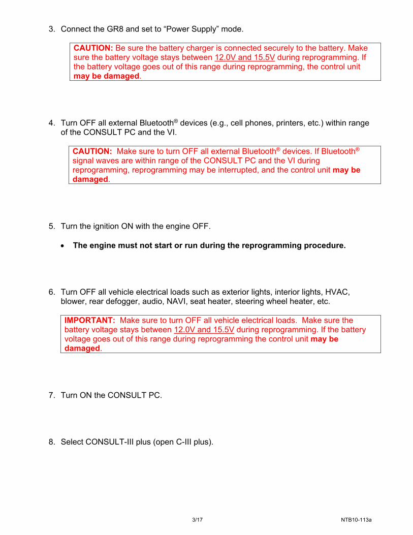
3. Connect the GR8 and set to “Power Supply” mode.
CAUTION: Be sure the battery charger is connected securely to the battery. Make sure the battery voltage stays between 12.0V and 15.5V during reprogramming. If the battery voltage goes out of this range during reprogramming, the control unit may be damaged.
4. Turn OFF all external Bluetooth® devices (e.g., cell phones, printers, etc.) within range
of the CONSULT PC and the VI.
CAUTION: Make sure to turn OFF all external Bluetooth® devices. If Bluetooth® signal waves are within range of the CONSULT PC and the VI during reprogramming, reprogramming may be interrupted, and the control unit may be damaged.
5. Turn the ignition ON with the engine OFF.
The engine must not start or run during the reprogramming procedure.
6. Turn OFF all vehicle electrical loads such as exterior lights, interior lights, HVAC, blower, rear defogger, audio, NAVI, seat heater, steering wheel heater, etc.
IMPORTANT: Make sure to turn OFF all vehicle electrical loads. Make sure the battery voltage stays between 12.0V and 15.5V during reprogramming. If the battery voltage goes out of this range during reprogramming the control unit may be damaged.
7. Turn ON the CONSULT PC.
8. Select CONSULT-III plus (open C-III plus).

4/17 NTB10-113a
9. Wait for the plus VI to be recognized.
Serial number will display when the plus VI is recognized.
Figure 1
10. Select Re/programming, Configuration.
Figure 2
Step 9: plus VI is recognized
Step 10

5/17 NTB10-113a
11. Use arrows (if needed) to view and read all precautions.
12. Check the box confirming the precautions have been read.
13. Select Next.
Figure 3
14. If the screen in Figure 4 displays, select Automatic Selection(VIN).
If the screen in Figure 4 does not display, skip to step 15.
Figure 4
Step 13
Step 12
Step 11
Example
Step 14

6/17 NTB10-113a
15. Verify the VIN or Chassis # matches that of the vehicle.
16. If the correct VIN is displayed, select Confirm.
Figure 5
17. Select Confirm again.
Figure 6
Step 15: Verify here
Step 16: If OK, select Confirm
Step 17
xxxxxx

7/17 NTB10-113a
18. Select ABS.
Use the scroll arrows as needed.
Figure 7
19. Wait for System Call to complete and then select Reprogramming.
Figure 8
Step 19
Step 18 Scroll
arrows
8/17 NTB10-113a
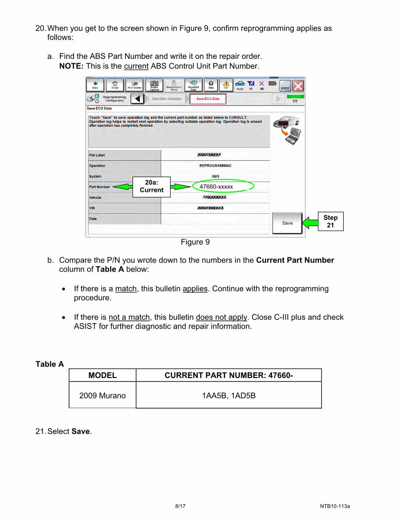
20. When you get to the screen shown in Figure 9, confirm reprogramming applies as follows:
a. Find the ABS Part Number and write it on the repair order.
NOTE: This is the current ABS Control Unit Part Number.
Figure 9
b. Compare the P/N you wrote down to the numbers in the Current Part Number
column of Table A below:
If there is a match, this bulletin applies. Continue with the reprogramming procedure.
If there is not a match, this bulletin does not apply. Close C-III plus and check ASIST for further diagnostic and repair information.
Table A
MODEL CURRENT PART NUMBER: 47660-
2009 Murano 1AA5B, 1AD5B
21. Select Save.
Step 21
20a: Current
xxxxxxxxx
xxxxx
x
xxxxxxxxx
xxxxxxxxxx
47660-xxxxx
9/17 NTB10-113a
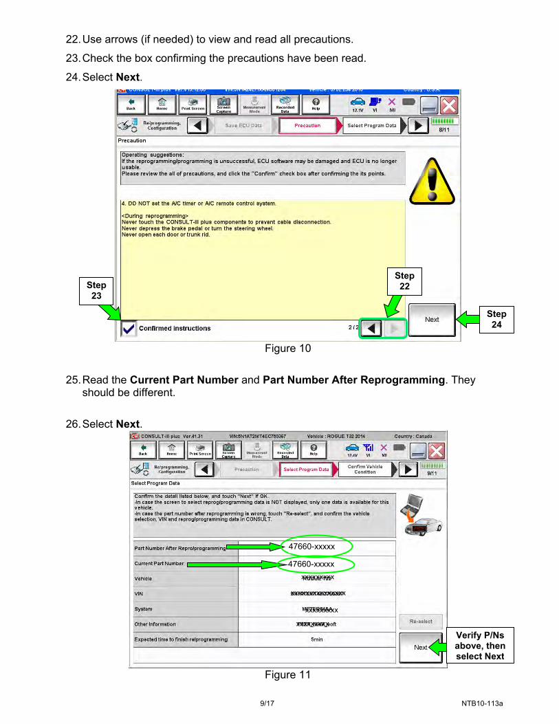
22. Use arrows (if needed) to view and read all precautions.
23. Check the box confirming the precautions have been read.
24. Select Next.
Figure 10
25. Read the Current Part Number and Part Number After Reprogramming. They
should be different.
26. Select Next.
Figure 11
Verify P/Ns above, then select Next
Step 24
Step 23
Step 22
46007-
xxxxxxxxx
xxxxxxxxx
xxxxxxxxx
xxxxxxxxxxxxxxx
47660-xxxxx
47660-xxxxx

10/17 NTB10-113a
27. Confirm battery voltage is correct, and then select Next.
NOTE: Battery voltage must stay within the specified range to make the indicator turn green.
Figure 12
28. Make sure OK is highlighted green and select Start.
IMPORTANT: Battery voltage must stay between 12.0 and 15.5 Volts during reprogramming or reprogramming may be interrupted and the control unit may be damaged.
Figure 13
Step 28
Monitor 12V battery
voltage here
Monitor 12V battery
voltage here
Must be “Green” before
selecting Next
Step 27
EXAMPLE

11/17 NTB10-113a
29. Select USA/CANADA Dealers. 30. Select OK.
Figure 14
NOTE: The above screen may not display if the CONSULT PC has remained ON since the
last reprogramming. If the CONSULT PC is not connected to the Internet, the screen in Figure 15 will
display.
Figure 15
Step 30
Step29

12/17 NTB10-113a
31. Enter Username and Password.
The CONSULT PC must be connected to the Internet (Wi-Fi or cable).
Before reprogramming will start, you will be required to enter your User Name and Password.
If you do not know your User Name and Password, contact your Service Manager. 32. Select Submit.
There will be a short pause while the username and password are authenticated.
Once authentication completes, TCM reprogramming will automatically begin and the screen in Figure 17 on the next page will be displayed.
Figure 16
Step 31
Step 32

13/17 NTB10-113a
33. Wait for both progress bars to complete.
Figure 17
34. When the screen in Figure 18 displays, the reprogramming is complete.
NOTE: If the screen in Figure 18 does not display (reprogramming does not complete), refer to the information on the next page.
35. Disconnect the battery charger from the vehicle.
36. Select Next.
Figure 18
NOTE: DTC Erase must be performed before C-III plus will provide the final reprogramming confirmation report. Continue with the reprogramming procedure on page 15.
Step 36

14/17 NTB10-113a
Control Unit Recovery:
Do not disconnect plus VI or shut down CONSULT-III plus if reprogramming does not complete.
If reprogramming does not complete and the “!?” icon displays as shown in Figure 19:
Figure 19
If reprogramming does not complete and the “X” icon displays as shown in Figure 20:
Figure 20
Check battery voltage (12.0–15.5 V).
Ignition is ON, engine OFF.
External Bluetooth® devices are OFF.
All electrical loads are OFF.
Select retry and follow the on screen instructions.
“Retry” may not go through on
the first attempt and can be selected more than once.
Check battery voltage (12.0 – 15.5 V).
CONSULT A/C adapter is plugged in.
Ignition is ON, engine OFF.
Transmission is in Park.
All C-III plus / VI cables are securely connected.
All C-III plus updates are installed.
Select Home, and restart the reprogram procedure from the beginning.
Select Retry
xxxxxxxxx

15/17 NTB10-113a
37. Erase all DTCs as follows:
a. Turn the ignition OFF.
b. Turn the ignition ON engine OFF.
c. Wait for DTC erase to complete.
Figure 21
ON
Turn ignition OFF > ON

16/17 NTB10-113a
38. Verify the part number has changed (before and after reprogramming part numbers
should be different).
a. Print a copy of the screen in Figure 22 by selecting Print.
b. Attach the copy to the repair order.
c. Once a copy has been printed, select Confirm.
Figure 22
NOTE: If you cannot print the above screen:
a. Select Screen Capture.
b. Name the file.
c. Save the file in My Documents.
A copy of the screen is now saved in the CONSULT PC. It can be retrieved and printed at a later time.
Step 38c
Step 38a
Step 38
xxxxx
xxxxxxxxxxxxx
xxxxxx
xxxxxxxxx
47660-xxxxx
47660-xxxxx
17/17 NTB10-113a
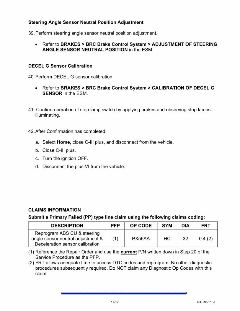
Steering Angle Sensor Neutral Position Adjustment
39. Perform steering angle sensor neutral position adjustment.
Refer to BRAKES > BRC Brake Control System > ADJUSTMENT OF STEERING ANGLE SENSOR NEUTRAL POSITION in the ESM.
DECEL G Sensor Calibration
40. Perform DECEL G sensor calibration.
Refer to BRAKES > BRC Brake Control System > CALIBRATION OF DECEL G SENSOR in the ESM.
41. Confirm operation of stop lamp switch by applying brakes and observing stop lamps
illuminating. 42. After Confirmation has completed:
a. Select Home, close C-III plus, and disconnect from the vehicle.
b. Close C-III plus.
c. Turn the ignition OFF.
d. Disconnect the plus VI from the vehicle. CLAIMS INFORMATION
Submit a Primary Failed (PP) type line claim using the following claims coding:
DESCRIPTION PFP OP CODE SYM DIA FRT
Reprogram ABS CU & steering angle sensor neutral adjustment &
Deceleration sensor calibration (1) PX56AA HC 32 0.4 (2)
(1) Reference the Repair Order and use the current P/N written down in Step 20 of the Service Procedure as the PFP.
(2) FRT allows adequate time to access DTC codes and reprogram. No other diagnostic procedures subsequently required. Do NOT claim any Diagnostic Op Codes with this claim.