2009 chevrolet silverado and gmc sierra two-mode …€¦ · · 2011-10-242009 chevrolet...
TRANSCRIPT

Seats and Restraint System ............................. 1-1Rear Seats ............................................... 1-2Restraint System Check .............................. 1-3
Features and Controls ..................................... 2-1Storage Areas ........................................... 2-2Starting and Operating Your Vehicle ........... 2-12
Instrument Panel ............................................. 3-1Climate Controls ........................................ 3-2Warning Lights, Gages, and Indicators .......... 3-3Driver Information Center (DIC) .................. 3-12Audio System(s) ....................................... 3-14
Driving Your Vehicle ....................................... 4-1Your Driving, the Road, and the Vehicle ....... 4-2Towing ..................................................... 4-2
Service and Appearance Care .......................... 5-1Service ..................................................... 5-2Checking Things Under the Hood ................. 5-3Electrical System ...................................... 5-21Appearance Care ..................................... 5-23Capacities and Specifications ..................... 5-24
Maintenance Schedule ..................................... 6-1Maintenance Schedule ................................ 6-2
Index ................................................................ 1
2009 Chevrolet Silverado andGMC Sierra Two-mode Hybrid M

GENERAL MOTORS, GM and the GM Emblem,CHEVROLET, the CHEVROLET Emblem, GMC, theGMC Emblem, and the names SILVERADO and SIERRAare registered trademarks of General Motors Corporation.
The information in this manual supplements the ownermanual. This manual includes the latest informationat the time it was printed. GM reserves the right to makechanges after that time without further notice.
Keep this manual in the vehicle for quick reference.
Canadian OwnersA French language copy of this manual can be obtainedfrom your dealer/retailer or from:
Helm, IncorporatedP.O. Box 07130Detroit, MI 48207
1-800-551-4123www.helminc.com
Propriétaires CanadiensOn peut obtenir un exemplaire de ce guide en françaisauprès de concessionnaire ou à l’adresse suivante:
Helm, IncorporatedP.O. Box 07130Detroit, MI 48207
1-800-551-4123www.helminc.com
IntroductionYour hybrid pickup is designed to be more fuel efficientthan the standard pickup, which results in reducedcarbon dioxide emissions.
Litho in U.S.A.Part No. 25785840 A First Printing ©2008 General Motors Corporation. All Rights Reserved.
ii

Using this SupplementThis supplement contains information specific to thehybrid components of the vehicle. It does not explaineverything you need to know about the vehicle.Read this supplement along with the owner manual tolearn about the vehicle’s features and controls.
IndexA good place to look for what you need is the Index inback of this supplement. It is an alphabetical list of what isin the supplement, and the page number where you willfind it.
iii

✍ NOTES
iv

Rear Seats .......................................................1-2Rear Seat Operation
(All Split Bench and Hybrid Full Bench) ..........1-2
Restraint System Check ...................................1-3Replacing Restraint System Parts
After a Crash .............................................1-3
Section 1 Seats and Restraint System
1-1

Rear Seats
Rear Seat Operation (All SplitBench and Hybrid Full Bench)
Folding Rear SeatOn a vehicle with a second row 60/40 split seat eitherside of the rear seat may be folded for added cargospace.
Notice: Folding a rear seat with the safety beltsstill fastened may cause damage to the seat or thesafety belts. Always unbuckle the safety beltsand return them to their normal stowed positionbefore folding a rear seat.
Make sure that nothing is on the seat.
To fold the seat, slowly pull the seat cushion up.
To return the seat to the normal seating position, slowlypull the seat cushion down.
{CAUTION:
A safety belt that is improperly routed, not properlyattached, or twisted will not provide the protectionneeded in a crash. The person wearing the beltcould be seriously injured. After raising the rearseatback, always check to be sure that the safetybelts are properly routed and attached, and arenot twisted.
1-2

Restraint System Check
Replacing Restraint System PartsAfter a CrashIf an airbag inflates or the vehicle has been in a crash,the vehicle’s sensing system may command theautomatic hybrid battery disconnect to open. The batterywill disconnect. The hybrid battery will be off and the
vehicle will not start. The airbag readiness light and/orSERVICE HYBRID SYSTEM message may come on inthe driver information center. See “Airbag ReadinessLight” in the owner manual and Driver Information Center(DIC) on page 3-12 for more information.
To operate the vehicle, the automatic hybrid batterydisconnect must be serviced by a qualified servicetechnician and sensing system parts will need to bereplaced. Have the vehicle serviced right away.
1-3

✍ NOTES
1-4
Storage Areas ..................................................2-2Tonneau Cover (Hard Tonneau) .......................2-2Tonneau Cover (Soft Tonneau) ........................2-7
Starting and Operating Your Vehicle ................2-12Starting the Vehicle .......................................2-12Automatic Transmission Operation ...................2-14Regenerative Braking ....................................2-18Running the Vehicle While Parked ..................2-18
Section 2 Features and Controls
2-1

Storage Areas
Tonneau Cover (Hard Tonneau)
Installing the Cover
{CAUTION:
An improperly stored cargo cover could be thrownabout the vehicle during a collision or suddenmaneuver. Someone could be injured. If the coveris removed, always store it in the proper storagelocation. After positioning the cargo cover back onthe vehicle, always be sure that it is securelyreattached by properly securing the straps andlatches.
1. Position the tonneau cover onto the top of thepickup box with the locator tabs positioned intothe front stake pockets.
2. Align the front edge of the cover with the front edgeof the bed rail so that it is centered on each side ofthe truck bed.
3. Lower the front clamp from its storage position.
2-2
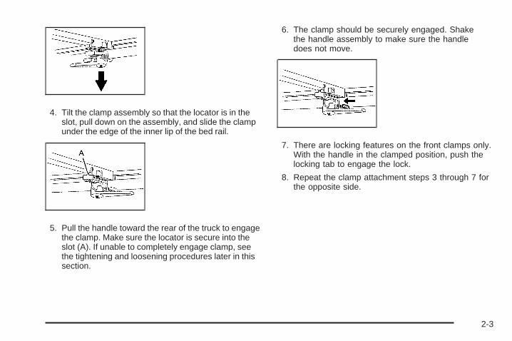
4. Tilt the clamp assembly so that the locator is in theslot, pull down on the assembly, and slide the clampunder the edge of the inner lip of the bed rail.
5. Pull the handle toward the rear of the truck to engagethe clamp. Make sure the locator is secure into theslot (A). If unable to completely engage clamp, seethe tightening and loosening procedures later in thissection.
6. The clamp should be securely engaged. Shakethe handle assembly to make sure the handledoes not move.
7. There are locking features on the front clamps only.With the handle in the clamped position, push thelocking tab to engage the lock.
8. Repeat the clamp attachment steps 3 through 7 forthe opposite side.
2-3

Closing the Cover
1. Release both the retention straps located on thetop of the cover behind the cab and press into thestored position.
2. Unfold the tonneau cover to the closed position.
3. Lower the rear set of clamp assemblies fromthe stored position.
4. Tilt the clamp assembly so that the locator is in theslot, pull down on the assembly, and slide the clampunder the edge of the inner lip on the bed rail.
5. Pull the handle toward the rear of the truck toengage the clamp. Make sure the locator is securedinto the slot (A). If unable to completely engageclamp, see the tightening and loosening procedureslater in this section.
6. The clamp should be securely engaged. Shakethe handle assembly to make sure the handledoes not move.
7. Repeat the clamp attachment steps 3 through 6 forthe opposite side.
8. Close the endgate.
2-4

Opening the Tonneau Cover1. Turn both of the rear handles inward to release
compression.
2. Pull the clamp down and turn the assemblies todisengage them from the lip of the pickup box.
3. Open the cover to expose the handles.
4. Align the clamp assembly bolt (A) with the retentionfeature (B).
5. Turn the handle assembly and clamp assembly boltsideways (A) into the slot of the retention feature (B).
6. The handle should lie flat on the panel with thehandles facing inward. Press firmly to secure.This step must be done before stowing the cover.
7. Fold the cover forward.
8. Remove the retaining strap from the bow. Connectthe retention buckle ends. One end is located onthe front of the tonneau cover behind the caband the other end is on the tonneau cover
9. Pull on each strap to make sure both buckles areattached.
2-5

Removing the Tonneau Cover1. Open the cover by following the procedure described
previously, under “Opening the Tonneau Cover”.
2. Disengage the locking tabs, located on the fronthandles, by pulling them rearward.
3. Turn the handles inward to release.
4. Pull the clamp down and turn the assembly todisengage it from the lip of the truck box.
5. Turn the cover to expose the handles.
6. Align the clamp assembly bolt (A), with the retentionfeature (B).
7. Turn the handle assembly sideways by tilting theassembly bolt (A) into the slot of the retentionfeature (B).
8. The handle should lie flat on the panel with thehandles facing inward. Press firmly to secure.
9. Remove the tonneau cover from the vehicle.
2-6
Tightening the Clamp1. Push the handle forward to release it from the
clamped position.
2. Disengage the clamp from the inner edge of thebed rail and slide the assembly inward.
3. Adjust the clamp height on the bolt by turning theentire clamp assembly counter-clockwise.
4. Attach the clamps as indicated in steps 4 and 5 ofInstalling the Cover.
Loosening the Clamp1. Return the handle to the fully disengaged position.
2. Disengage the clamp from the inner edge of thebed rail and slide the assembly inward.
3. Adjust the clamp height by turning the entire clampassembly clockwise.
4. Reattach the clamps as indicated in steps 4 and 5of Installing the Cover.
Tonneau Cover (Soft Tonneau)
Side Rail
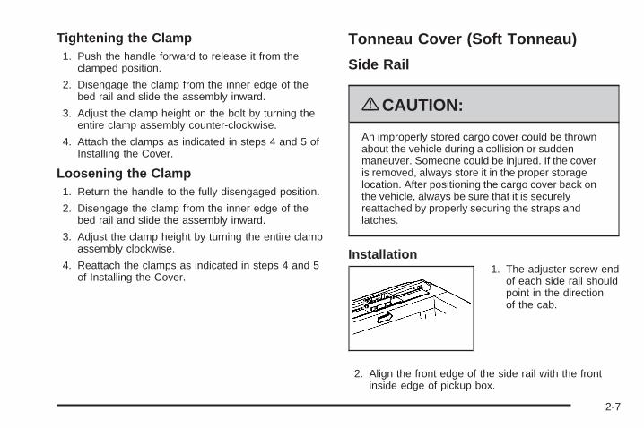
{CAUTION:
An improperly stored cargo cover could be thrownabout the vehicle during a collision or suddenmaneuver. Someone could be injured. If the coveris removed, always store it in the proper storagelocation. After positioning the cargo cover back onthe vehicle, always be sure that it is securelyreattached by properly securing the straps andlatches.
Installation1. The adjuster screw end
of each side rail shouldpoint in the directionof the cab.
2. Align the front edge of the side rail with the frontinside edge of pickup box.
2-7

Clamp
Installation
1. Position three outer clamps (A), on each side rail.The positions on the siderails are marked CLAMP.
2. Position the grooves ofthe clamps on the siderails (A) using thecenter groove (B).
3. If the pickup boxhas molded bed railprotectors (A), removethe insert (C) fromthe outer groove on theclamp, and positionthe clamp on the siderail (B) using theouter groove (D).
2-8

4. Slide the innerclamp (B) into the outerclamp (A).
5. Turn the latch (C) ontothe outer clamp.
6. Tighten the clamp by turning the latch (C) towardthe side rail.
7. If the truck box has a molded bed rail protector,insert the latch into the top notch on the innerclamp.
AdjustmentIf there is excessive sideways movement of thecrossrails, move and re-install the clamps on the looseareas using the inner groove of the clamp.
Cover
Installation
1. Place the cover assembly into the front pivotmounts to lock the latches into place on both endsof the front rail.
2. Firmly press down on each side of the cover, untilthe latches are secured into the side rails.
2-9

3. Release both straps on the cover. Roll the coverout. Each bow should fall between the side rails.
4. When the cover is rolled out, place the rear rail intothe rear pivot mounts. Press firmly down on thedriver side until the latch is secured into theside rails. Only the driver side has a latch.
5. Secure the driver side of the cover to the side rail.Then pull the cover tight across the bed and fastenthe passenger side.
2-10
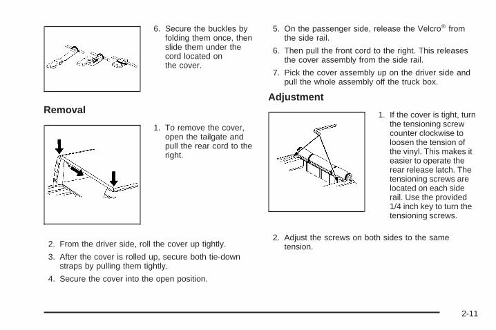
6. Secure the buckles byfolding them once, thenslide them under thecord located onthe cover.
Removal
1. To remove the cover,open the tailgate andpull the rear cord to theright.
2. From the driver side, roll the cover up tightly.
3. After the cover is rolled up, secure both tie-downstraps by pulling them tightly.
4. Secure the cover into the open position.
5. On the passenger side, release the Velcro® fromthe side rail.
6. Then pull the front cord to the right. This releasesthe cover assembly from the side rail.
7. Pick the cover assembly up on the driver side andpull the whole assembly off the truck box.
Adjustment
1. If the cover is tight, turnthe tensioning screwcounter clockwise toloosen the tension ofthe vinyl. This makes iteasier to operate therear release latch. Thetensioning screws arelocated on each siderail. Use the provided1/4 inch key to turn thetensioning screws.
2. Adjust the screws on both sides to the sametension.
2-11

Starting and Operating YourVehicle
Starting the Vehicle
{CAUTION:
Exiting the vehicle, without first shifting intoP (Park), may cause the vehicle to move, and youor others can be seriously injured. Because thevehicle has the Automatic Engine Start/Stopfeature, the vehicle’s engine might seem to be shutoff when you come to a complete stop. However,once the brake pedal is released, the vehicle canmove. The vehicle’s engine can also restart atany time.
Shift to P (Park) and turn the ignition to LOCK/OFF,before exiting the vehicle.
Start the engine as you would any other engine. See“Starting the Engine” in the owner manual for moreinformation on starting. The hybrid system provides veryquiet engine starting. If pulling a trailer with trailer brakes,see Towing a Trailer on page 4-2 for more information.
Auto StopThe vehicle has an Auto Stop feature. After a successfulengine start, the engine may turn off and operate inthe Auto Stop mode. Some of the vehicle conditions thatallow the engine to stop running and enter the AutoStop mode are:
• Ignition switch is in the ON/RUN position.
• The hood is closed.
• The gear selector is in P (Park), N (Neutral) orD (Drive).
• The hybrid battery is at an acceptable state ofcharge.
• The hybrid battery voltage, temperature or powerlimits are not exceeded. In very hot conditions,Auto Stop may be unavailable until the hybridbattery has cooled.
• The engine is at operating temperature.
If you are on an incline, the hybrid drive motor can helpkeep the vehicle from rolling backwards, even if theengine is in Auto Stop.
With your foot off the brake and the vehicle on levelground, the hybrid drive motor may cause the vehicle toroll slowly forward, even when the engine is in Auto Stop.
Keep your foot firmly on the brake pedal until you areready for the vehicle to move.
2-12

Engine OFF and AUTO STOP modes are indicated onthe tachometer display. When the tachometer needleindicates OFF, the engine is not running and will remainoff until the ignition key is placed in the START position ora remote vehicle start is performed. When the tachometerneedle indicates AUTO STOP, the hybrid system is on,the engine is not running, but may Auto Start at any timewithout notice. See Tachometer on page 3-4 for moreinformation.
A chime will sound if the driver door is opened while inAuto Stop as a reminder that the ignition switch isnot in the LOCK/OFF position. Always turn the ignitionswitch to LOCK/OFF and remove the key from theignition switch when exiting the vehicle.
Auto StartThe vehicle also has an Auto Start feature. The enginewill remain off while in Auto Stop mode until vehicleconditions require the engine to run. The near-instantstarting of the engine from Auto Stop mode is calledAuto Start. Some of the vehicle conditions thatmay cause the engine to Auto Start are:
• The hood is opened.
• The gear selector is in M (Manual Mode) orR (Reverse).
• The hybrid battery state of charge is too low.
• The hybrid battery voltage, temperature or powerlimits are exceeded.
• The engine is not at operating temperature.
• Acceleration demands require the use of the engine.
EV ModeThe vehicle also has an EV mode which uses onlythe electric motor to move the vehicle. With lightacceleration, the vehicle will drive in EV mode. EV modeis unavailable when the vehicle is out of fuel.
If increased acceleration is required, or the vehiclereaches approximately 30 mph (40 km/h), the enginewill start automatically. The engine shuts off at speedsbelow 25 mph (40 km/h) unless the transmission isin M (Manual Mode) or Auto Stop is disabled.
During heavy acceleration, both the engine and hybridelectric motors supply power. A sensation similar to atransmission gear change can be felt as the transmissionchanges modes. Engine RPM may remain above4,000 RPM for a longer period during hard acceleration.
2-13

Automatic Transmission OperationThe vehicle has an electronic shift position indicatorwithin the instrument panel cluster.
There are several different positions for the shift lever.
See “Range Selection Mode” later in this section.
P (Park): This position locks the rear wheels. It is thebest position to use when you start the engine becausethe vehicle cannot move easily.
When parked on a hill, especially when the vehicle has aheavy load, you may notice an increase in the effort toshift out of P (Park). See “Shifting Into P (Park)” in theIndex of vehicle’s owner manual for more information.
{CAUTION:
It is dangerous to get out of the vehicle if the shiftlever is not fully in P (Park) with the parking brakefirmly set. The vehicle can roll.
Do not leave the vehicle when the engine isrunning unless you have to. If you have left theengine running, the vehicle can move suddenly.You or others could be injured. To be sure thevehicle will not move, even when you are on fairlylevel ground, always set the parking brake andmove the shift lever to P (Park). See Shifting IntoPark in the Owner Manual. If you are pulling atrailer, see Towing a Trailer on page 4-2.
2-14

{CAUTION:
If you have Four-Wheel Drive, the vehiclewill be free to roll — even if the shift lever is inP (Park) — if the transfer case is in Neutral. So, besure the transfer case is in a drive gear, Two-WheelDrive High or Four-Wheel Drive High or Four-WheelDrive Low — not in Neutral. See “Shifting Into Park”in the Owner Manual.
R (Reverse): Use this gear to back up.
Notice: Shifting to R (Reverse) while the vehicle ismoving forward could damage the transmission.The repairs would not be covered by the vehiclewarranty. Shift to R (Reverse) only after the vehicleis stopped.
To rock the vehicle back and forth to get out of snow, ice,or sand without damaging the transmission, see “If YourVehicle is Stuck in Sand, Mud, Ice, or Snow” in the Indexof the vehicle’s owner manual.
N (Neutral): In this position, the engine andtransmission are not connected with the wheels.To restart the engine when the vehicle is alreadymoving, use N (Neutral) only.
{CAUTION:
Shifting into a drive gear while the engine isrunning at high speed is dangerous. Unless yourfoot is firmly on the brake pedal, the vehicle couldmove very rapidly. You could lose control and hitpeople or objects. Do not shift into a drive gearwhile the engine is running at high speed.
Notice: Shifting out of P (Park) or N (Neutral) withthe engine running at high speed may damagethe transmission. The repairs would not be coveredby the vehicle warranty. Be sure the engine isnot running at high speed when shifting the vehicle.
D (Drive): This position is for normal driving. Itprovides the best fuel economy. If you need morepower for passing, and you are:
• Going less than about 35 mph (55 km/h), push theaccelerator pedal about halfway down.
• Going about 35 mph (55 km/h) or more, push theaccelerator all the way down.
2-15

D (Drive) or M (Manual Mode) can be used whentowing a trailer, carrying a heavy load, driving on steephills, or for off-road driving. You may want to shift thetransmission to a lower gear selection if the transmissionshifts too often.
Downshifting the transmission in slippery road conditionscould result in skidding. See “Skidding” under “Loss ofControl” in the owner manual for more information.
When temperatures are very cold, the transmission’sgear shifting may be delayed, providing more stableshifts until the engine warms up. Shifts may be morenoticeable with a cold transmission. This differencein shifting is normal.
M (Manual Mode): This position lets drivers select therange of gears appropriate for current driving conditions.If the vehicle has this feature, see “Range SelectionMode” later in this section.
Notice: Spinning the tires or holding the vehicle inone place on a hill using only the accelerator pedalmay damage the transmission. The repair will not becovered by the vehicle warranty. If you are stuck, donot spin the tires. When stopping on a hill, use thebrakes to hold the vehicle in place.
The vehicle has a shift stabilization feature that adjuststhe transmission shifting to the current driving conditionsto reduce rapid upshifts and downshifts. If the shiftstabilization feature determines that a current vehiclespeed cannot be maintained, the transmission does notupshift. In some cases, this may appear to be a delayedshift, however the transmission is operating normally.
2-16

Range Selection Mode
The Range Selection Mode controls the vehicle’stransmission.
To use this feature:
1. Move the shift lever to the M (Manual Mode).
2. Press the plus/minus button to upshift or downshiftselecting the desired range of gears.
A number displays next to the M, indicating the currentgear that has been selected. The number displayed inthe gear indicator is the highest gear that can be used.
The vehicle can automatically shift to lower gears as itadjusts to driving conditions. When 3 (Third) is selected,1 (First) through 3 (Third) gears are automatically shiftedby the vehicle, but 4 (Fourth) cannot be used until it isselected.
The Range Selection Mode controls the vehicle andengine speed while driving down a hill or towing a trailer,by allowing you to select a desired range of gears.
When you move the shift lever into M, the transmissionwill default to M4. In this gear range, effective enginebraking occurs at speeds above 45 mph (72 km/h).
Pushing the minus (−) button on the shift lever reducesthe gear range.
In the M3 gear range, effective engine braking occurs atspeeds above 35 mph (56 km/h).
In the M2 gear range, effective engine braking occurs atspeeds above 25 mph (40 km/h).
In the M1 gear range, effective engine braking occurs atspeeds above 10 mph (16 km/h).
When operating in M (Manual Mode), Auto Stop isdisabled. For better vehicle efficiency, operate thevehicle in D (Drive) not M (Manual Mode).
Cruise control can be used while using the RangeSelection Mode.
2-17

Regenerative BrakingRegenerative braking is a hybrid technology that enablesthe electric drive motor to operate as a generator whencoasting or braking. Energy from the moving vehiclerecharges the hybrid battery.
The hydraulic disc brakes work with the regenerativebraking to insure effective braking, such as when a highbraking demand is requested.
The braking system is computer controlled and blendsthe regenerative braking with the conventional hydraulicdisc brakes to meet any requirements for deceleration.The controller interprets the braking request and usesregenerative braking, conventional hydraulic braking or acombination of both as necessary. Because the controllerapplies the hydraulic brakes through its high pressureaccumulator, you may occasionally hear the motor drivenpump when it recharges the system. This is normal.
See “Warning Lights, Gages, and Indicators” and “DriverInformation Center (DIC)” in the Index of the ownermanual. In the event of a controller problem, the brakepedal may be harder to push and the stopping distancemay be longer.
Running the Vehicle While ParkedIt is better not to park with the engine running. But if youever have to, here are some things to know.
{CAUTION:
Exiting the vehicle, without first shifting intoP (Park), may cause the vehicle to move, and youor others can be seriously injured. Because thevehicle has the Automatic Engine Start/Stopfeature, the vehicle’s engine might seem to be shutoff when you come to a complete stop. However,once the brake pedal is released, the vehicle canmove. The vehicle’s engine can also restart atany time.
Shift to P (Park) and turn the ignition to LOCK/OFF,before exiting the vehicle.
Follow the proper steps to be sure the vehicle will notmove. See “Shifting Into Park” in the owner manualfor more information.
If you are pulling a trailer, see Towing a Trailer onpage 4-2 for more information.
2-18
Climate Controls ..............................................3-2Warning Lights, Gages, and Indicators ..............3-3
Instrument Panel Cluster .................................3-3Tachometer ...................................................3-4Charging System Light ....................................3-4Fuel Economy Gage .......................................3-5Brake System Warning Light ............................3-5Antilock Brake System (ABS) Warning Light .......3-7StabiliTrak® Indicator Light ...............................3-7
Engine Coolant Temperature Gage ...................3-8Oil Pressure Gage ..........................................3-8Oil Pressure Light .........................................3-10Fuel Gage ...................................................3-11
Driver Information Center (DIC) .......................3-12DIC Warnings and Messages .........................3-12
Audio System(s) .............................................3-14Navigation/Radio System ...............................3-14
Section 3 Instrument Panel
3-1

Climate ControlsFor more information on the vehicle’s climate controlsystem, see “Climate Control System” in the ownermanual.
Electric Air Conditioning CompressorThis hybrid vehicle has a electrically powered airconditioning compressor. This allows for continuousair conditioning operation and passenger comfort,even while the hybrid engine cycles on and off.
When operating the climate control system, selectthe AUTO mode and the desired temperature setting.The climate control system automatically adjusts the fanspeed and airflow direction. The climate control systemcontinues to adjust the climate control settings chosenfor best use of electrical power.
To get maximum engine off time during mildtemperatures, select a warmer temperature setting orturn off the air conditioning to shut off the compressor.During hot weather, it is recommended to keep theair conditioning on with the windows closed. Continuousair conditioning use can cause the engine to autostartmore frequently.
Some noise may be heard occasionally from thecompressor, especially when air conditioning useis high and the engine has turned off.
3-2
Warning Lights, Gages, and IndicatorsInstrument Panel Cluster
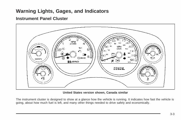
The instrument cluster is designed to show at a glance how the vehicle is running. It indicates how fast the vehicle isgoing, about how much fuel is left, and many other things needed to drive safely and economically.
United States version shown, Canada similar
3-3

Tachometer
When the gas engine is off and the key is in theON/RUN position, the position of the tachometerindicator shows the state of the vehicle:
• AUTO STOP position indicates that the vehicle isstill able to move and the engine could restart, byan Auto Start, at any time.
• OFF position indicates that the engine is off.
When the engine is on, the tachometer indicator showsthe engine’s revolutions per minute (rpm).
Charging System Light
This light will comeon briefly when theignition is turned toACC/ACCESSORY orON/RUN, but the engineis not running, as a checkto show it is working.
It should go out once the engine has been started. If itstays on, or comes on while driving, there could be aproblem with the charging system. A charging systemDriver Information Center (DIC) message may alsoappear. See DIC Warnings and Messages on page 3-12for more information. This light could indicate that thereare electrical problems. Have it checked right away. If ashort distance must be driven with the light on, be certainto turn off all the accessories, such as the radio and airconditioner.
United States Versionshown, Canada similar
3-4
Fuel Economy Gage
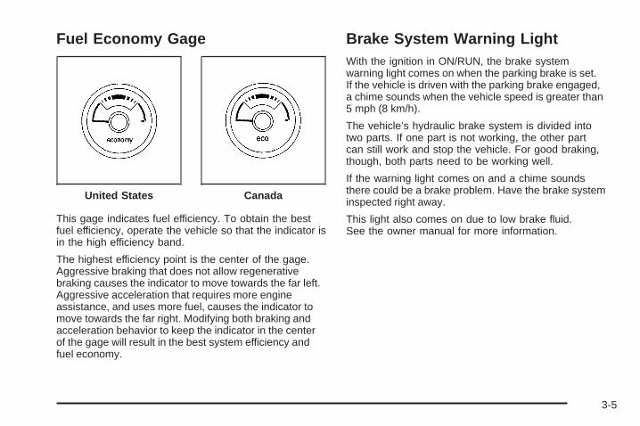
This gage indicates fuel efficiency. To obtain the bestfuel efficiency, operate the vehicle so that the indicator isin the high efficiency band.
The highest efficiency point is the center of the gage.Aggressive braking that does not allow regenerativebraking causes the indicator to move towards the far left.Aggressive acceleration that requires more engineassistance, and uses more fuel, causes the indicator tomove towards the far right. Modifying both braking andacceleration behavior to keep the indicator in the centerof the gage will result in the best system efficiency andfuel economy.
Brake System Warning LightWith the ignition in ON/RUN, the brake systemwarning light comes on when the parking brake is set.If the vehicle is driven with the parking brake engaged,a chime sounds when the vehicle speed is greater than5 mph (8 km/h).
The vehicle’s hydraulic brake system is divided intotwo parts. If one part is not working, the other partcan still work and stop the vehicle. For good braking,though, both parts need to be working well.
If the warning light comes on and a chime soundsthere could be a brake problem. Have the brake systeminspected right away.
This light also comes on due to low brake fluid.See the owner manual for more information.
United States Canada
3-5

This light should come on briefly when the ignitionkey is turned to ON/RUN. If it does not come on then,have it fixed so it will be ready to warn if there is aproblem.
{CAUTION:
The brake system might not be working properly ifthe brake system warning light is on. Driving withthe brake system warning light on can lead to acrash. If the light is still on after the vehicle hasbeen pulled off the road and carefully stopped,have the vehicle towed for service.
If the light comes on while driving, pull off the road andstop carefully. The pedal might be harder to push orcan go closer to the floor. It may take longer to stop.If the light does not go out, have the vehicle towed forservice. See Towing Your Vehicle on page 4-2.
United States Canada
3-6

Antilock Brake System (ABS)Warning Light
For vehicles with theAntilock Brake System(ABS), this light comes onbriefly when the engineis in ON/RUN.
That is normal. If the light does not come on then, haveit fixed so it will be ready to warn if there is a problem.
If the ABS light stays on, turn the ignition off, if thelight comes on while driving, stop as soon as it is safelypossible and turn the ignition off. Then start the engineagain to reset the system. If the ABS light still stays on, orcomes on again while driving, the vehicle needs service.If the regular brake system warning light is not on, thevehicle still has brakes, but not antilock brakes. If theregular brake system warning light is also on, the vehicledoes not have antilock brakes and there is a problem withthe regular brakes. See Brake System Warning Light onpage 3-5.
For vehicles with a Driver Information Center (DIC),see DIC Warnings and Messages on page 3-12 for allbrake related DIC messages.
StabiliTrak® Indicator Light
For vehicles withStabiliTrak, this warninglight comes on briefly whenthe ignition is in ON/RUN.
If it does not, have the vehicle serviced by yourdealer/retailer. If the system is working normally theindicator light goes off.
If the light comes on and stays on while driving, therecould be a problem with the StabiliTrak system and thevehicle might need service. When this warning light is on,the StabiliTrak system is off and does not limit wheel spin.
The light flashes if the system is active and is workingto assist the driver with directional control of thevehicle in difficult driving conditions.
See the owner manual for more information.
3-7
Engine Coolant Temperature Gage
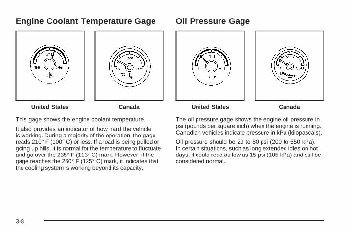
This gage shows the engine coolant temperature.
It also provides an indicator of how hard the vehicleis working. During a majority of the operation, the gagereads 210° F (100° C) or less. If a load is being pulled orgoing up hills, it is normal for the temperature to fluctuateand go over the 235° F (113° C) mark. However, if thegage reaches the 260° F (125° C) mark, it indicates thatthe cooling system is working beyond its capacity.
Oil Pressure Gage
The oil pressure gage shows the engine oil pressure inpsi (pounds per square inch) when the engine is running.Canadian vehicles indicate pressure in kPa (kilopascals).
Oil pressure should be 29 to 80 psi (200 to 550 kPa).In certain situations, such as long extended idles on hotdays, it could read as low as 15 psi (105 kPa) and still beconsidered normal.
United States Canada United States Canada
3-8

A reading in the low pressure zone may be caused by adangerously low oil level or some other problem causinglow oil pressure. Check the oil as soon as possible.
{CAUTION:
Do not keep driving if the oil pressure is low.The engine can become so hot that it catches fire.Someone could be burned. Check the oil as soonas possible and have the vehicle serviced.
Notice: Lack of proper engine oil maintenancecan damage the engine. The repairs would not becovered by the vehicle warranty. Always followthe maintenance schedule in this manual forchanging engine oil.
AUTO STOPWhen the engine goes into Automatic Engine Stop, theoil pressure gage drops to zero when the tachometer is atthe AUTO STOP position. This is normal and oil pressurereturns to the normal operating range once the enginestarts.
See Starting the Vehicle on page 2-12 for moreinformation.
AUTO STOP displays in the Driver InformationCenter (DIC) when the vehicle speed is zero.See DIC Warnings and Messages on page 3-12for more information.
3-9

Oil Pressure Light
{CAUTION:
Do not keep driving if the oil pressure is low.The engine can become so hot that it catches fire.Someone could be burned. Check the oil as soonas possible and have the vehicle serviced.
Notice: Lack of proper engine oil maintenancecan damage the engine. The repairs would not becovered by the vehicle warranty. Always followthe maintenance schedule in this manual forchanging engine oil.
This light comes on brieflyas a check it works, whenthe ignition is in ON/RUN.If it does not, have thevehicle serviced.
If the light comes on and stays on, it means that oil isnot flowing through the engine properly. The vehiclecould be low on oil and might have some other systemproblem.
During an AUTO STOP there is zero oil pressure, butthis light will not come on.
3-10

Fuel Gage
When the ignition is on, the fuel gage showsapproximately how much fuel is left in the fuel tank.An arrow on the fuel gage indicates the side of the vehiclethe fuel door is on. The gage first indicates E (empty)before the vehicle is out of fuel, but the vehicle shouldbe refueled as soon as possible.
Listed are four situations that may occur with the fuelgage, none of these indicate a problem:
• At the gas station, the fuel pump shuts off beforethe gage reads F (full).
• It takes a little more or less fuel to fill up than thefuel gage indicated. For example, the gage mayhave indicated the tank was half full, but it actuallytook a little more or less than half the tank’scapacity to fill the tank.
• The gage moves a little while turning a corner orwhile accelerating.
• The gage does not go back to E (empty) when theignition is turned off.
United States Canada
3-11

Driver Information Center (DIC)Trip/Fuel Menu ItemsPress the trip/fuel button to display the battery voltage.For more items see “DIC Operation and Displays” inthe owner manual.
BATTERY VOLTAGEThis display shows the current battery voltage.If the voltage is in the normal range, the value will display.For example, the display may read BATTERY VOLTAGE13.2 VOLTS. If the voltage is high or low, the display willread HIGH or LOW. Your vehicle’s charging systemregulates voltage based on the state of the battery.The battery voltage may fluctuate when viewing thisinformation on the DIC. This is normal. See “ChargingSystem Light” in the owner manual for more information.If there is a problem with the battery charging system,the DIC will display a message. See DIC Warnings andMessages on page 3-12.
INST (Instantaneous) ECONOMYThis display normally shows instantaneous fueleconomy. When the vehicle is in Auto Stop modeAUTO STOP will be displayed. See Starting the Vehicleon page 2-12 for more information. The display may
also show if the vehicle is currently in V4 MODE orV8 MODE. See “Active Fuel Management” in the ownermanual for more information.
DIC Warnings and MessagesWarning messages are displayed on the DIC tonotify the driver that the status of the vehicle has changedand that some action may be needed by the driver tocorrect the condition. If there is more than one messagethat needs to be displayed they will appear one afteranother. Some messages may not require immediateaction but you should press the select button or the tripodometer reset stem on the instrument panel cluster toacknowledge that you received the message and clearit from the display. Some messages cannot be clearedfrom the display because they are more urgent; thesemessages require action before they can be removedfrom the DIC display. The following are the possiblemessages that can be displayed and some informationabout them. For information on other DIC messages,see “DIC Warnings and Messages” in the owner manualIndex.
3-12

SERVICE BATTERY CHARGINGSYSTEMIf the hybrid battery system faults or fails this messagewill appear on the DIC. The engine auto stop featurewill be disabled and the battery/charging system lightwill appear in the instrument panel cluster. See “BatteryWarning Light” in the owner manual Index.
Driving with this light on could drain your batteries.Have the electrical system checked as soon as possible.Pressing the select button or the trip odometer resetstem on the instrument panel cluster will acknowledgethis message and clear it from the DIC display.
HOOD OPENIf the hood is not fully closed or there is a problemwith the hood switch, this message will be displayed.Close the hood to clear the message. If the HOOD OPENmessage continues to be displayed after verifying thehood is closed, you should have the hood switchserviced. Pressing the select button or the trip odometerreset stem on the instrument panel cluster willacknowledge this message and clear it from the DICdisplay.
When this message is displayed, the auto stop functionwill not operate. If the vehicle is in auto stop mode whenthis message appears, the engine will instantly start.
OIL PRESSURE LOW STOP ENGINEIf engine oil pressure is low, this message will bedisplayed on the DIC. Stop the vehicle as soon as safelypossible and do not operate it until the cause of thelow oil pressure has been corrected. Check your oil levelas soon as possible and have your vehicle serviced.See “Engine Oil” in the owner manual Index.
SERVICE BRAKE SYSTEMThis message will be displayed if there is a problemwith the brake system. You will still be able to brake,but it will be noticeably more difficult. Pull off the roadto a safe location and have your vehicle towed tothe nearest dealer/retailer for service. See “Brakes,”“Brake System Warning Light,” and “ABS BrakeSystem Warning Light” in the owner manual Index.
SERVICE HYBRID SYSTEMIf this message is displayed on the DIC, the vehicle maycontinue to operate, but you need to have it servicedas soon as possible.
SERVICE POWER STEERINGThis message displays if a problem has been detectedwith the electric power steering. Have your vehicleserviced by your dealer/retailer immediately.
3-13
Audio System(s)
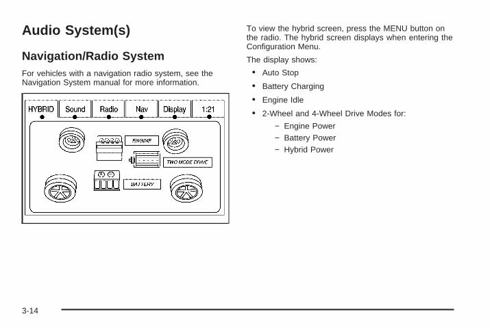
Navigation/Radio SystemFor vehicles with a navigation radio system, see theNavigation System manual for more information.
To view the hybrid screen, press the MENU button onthe radio. The hybrid screen displays when entering theConfiguration Menu.
The display shows:
• Auto Stop
• Battery Charging
• Engine Idle
• 2-Wheel and 4-Wheel Drive Modes for:
− Engine Power− Battery Power− Hybrid Power
3-14

Your Driving, the Road, and the Vehicle ............4-2Electric Power Steering ...................................4-2
Towing ............................................................4-2Towing Your Vehicle .......................................4-2Towing a Trailer .............................................4-2
Section 4 Driving Your Vehicle
4-1

Your Driving, the Road, andthe Vehicle
Electric Power SteeringThis vehicle has On-Demand Electric-Assist PowerSteering instead of conventional full-time hydraulicpower steering. It uses electricity supplied by the samebattery which is re-charged by the regenerativebraking system.
Because the system is On-Demand Electric-Assist,energy is used only when the steering wheel is turned,or when the steering gear is used to help isolate theforces of rough roads. This system does not use powersteering fluid, making it maintenance-free.
Towing
Towing Your VehicleConsult your dealer/retailer or a professional towingservice if the disabled vehicle needs to be towed.
Towing a TrailerFor more information, see “Towing a Trailer” in theowner manual Index.
Weight of the TrailerHow heavy can a trailer safely be?
It depends on how the rig is used. For example, speed,altitude, road grades, outside temperature and how muchthe vehicle is used to pull a trailer are all important. It candepend on any special equipment on the vehicle, and theamount of tongue weight the vehicle can carry.
4-2

Maximum trailer weight is calculated assuming only thedriver is in the tow vehicle and it has all the requiredtrailering equipment. The weight of additional optionalequipment, passengers and cargo in the tow vehiclemust be subtracted from the maximum trailer weight.
Use the following charts to determine how much thevehicle can weigh, based upon the vehicle model andoptions.
Vehicle Axle Ratio Maximum Trailer Weight GCWR*2WD 6.0 L V8 3.08 6,100 lbs (2 767 kg) 12,000 lbs (5 443 kg)4WD 6.0 L V8 3.08 5,900 lbs (2 676 kg) 12,000 lbs (5 443 kg)*The Gross Combination Weight Rating (GCWR) is the total allowable weight of the completely loaded vehicle andtrailer including any passengers, cargo, equipment and conversions. The GCWR for the vehicle should not beexceeded.
Trailer BrakesIf a trailer is being towed that has trailer brakes and thetrailer brakes are manually applied while driving slowerthan 25 mph (40 km/h), the vehicle may go into autostop mode even if the brakes are not being pressed.Using the trailer brake system manually can make thehybrid vehicle perform as if the brake pedal in the vehicle
is being pressed. The trailer brake operation check willstill work. If the trailer brakes are manually applied for anextended period of time, the SERVICE BRAKE SYSTEMDIC message comes on. The message goes off after thetrailer brakes have been released. No other action isnecessary. For more information, see “Trailer Brakes” inthe Index of the vehicle’s owner manual.
4-3

✍ NOTES
4-4

Service ............................................................5-2Doing Your Own Service Work .........................5-2
Checking Things Under the Hood .....................5-3High Voltage Devices and Wiring ......................5-3Engine Compartment Overview .........................5-4Automatic Transmission Fluid ...........................5-5Drive Motor/Generator Control Module (DMCM)
Coolant Surge Tank Pressure Cap ..................5-6Drive Motor/Generator Control Module (DMCM)
Cooling System ...........................................5-6Power Steering Fluid .....................................5-11
Brakes ........................................................5-11Battery ........................................................5-15Jump Starting ...............................................5-16
Electrical System ............................................5-21High Voltage Devices and Wiring ....................5-21Fuses and Circuit Breakers ............................5-21Underhood Fuse Block ..................................5-22
Appearance Care ............................................5-23Vehicle Care/Appearance Materials ..................5-23
Capacities and Specifications ..........................5-24
Section 5 Service and Appearance Care
5-1

Service
Doing Your Own Service Work
{CAUTION:
Never try to do your own service on hybridcomponents. You can be injured and the vehiclecan be damaged if you try to do your own servicework. Service and repair of these hybridcomponents should only be performed by atrained service technician with the properknowledge and tools.
{CAUTION:
You can be injured and the vehicle could bedamaged if you try to do service work on a vehiclewithout knowing enough about it.
• Be sure you have sufficient knowledge,experience, the proper replacement parts,and tools before attempting any vehiclemaintenance task.
• Be sure to use the proper nuts, bolts, andother fasteners. English and metric fastenerscan be easily confused. If the wrong fastenersare used, parts can later break or fall off.You could be hurt.
5-2
If doing some of your own service work, use the properservice manual. It tells you much more about how toservice the vehicle than this manual can. To orderthe proper service manual, see “Service PublicationsOrdering Information” in the owner manual.
This vehicle has an airbag system. Before attemptingto do your own service work, see “Servicing YourAirbag-Equipped Vehicle” in the owner manual.
Keep a record with all parts receipts and list themileage and the date of any service work performed.See “Maintenance Record” in the owner manual.
Checking Things Underthe Hood
High Voltage Devices and Wiring
{CAUTION:
Exposure to high voltage can cause shock, burns,and even death. The high voltage systems in yourvehicle can only be serviced by technicians withspecial training.
High voltage devices are identified by labels.Do not remove, open, take apart, or modify thesedevices. High voltage cable or wiring has orangecovering. Do not probe, tamper with, cut, or modifyhigh voltage cable or wiring.
5-3

Engine Compartment OverviewWhen you open the hood on your vehicle, you will see:
5-4

A. See “Engine Air Cleaner/Filter” in the owner manual.B. Drive Motor/Generator Control Module (DMCM).
See Drive Motor/Generator Control Module (DMCM)Cooling System on page 5-6.
C. Engine Oil Dipstick. See “Engine Oil” in the ownermanual.
D. Automatic Transmission Fluid Dipstick. SeeAutomatic Transmission Fluid on page 5-5.
E. Brake Fluid Reservoir. See Brakes on page 5-11.F. See “Underhood Fuse Block” in the owner manual.G. See “Windshield Washer Fluid” in the owner
manual.H. Hybrid Auxiliary Fuse Block. See Underhood Fuse
Block on page 5-22.I. DMCM Coolant Surge Tank Pressure Cap. See
Drive Motor/Generator Control Module (DMCM)Coolant Surge Tank Pressure Cap on page 5-6.
J. See “Coolant Surge Tank Pressure Cap” inthe owner manual.
K. Engine Oil Fill Cap. See “Engine Oil” in the ownermanual.
Automatic Transmission FluidFor more information, see “Automatic TransmissionFluid” in the owner manual Index.
Checking the Fluid Level
Your vehicle’s automatic transmission dipstick looks likethis. For more information on location, see EngineCompartment Overview on page 5-4.
5-5

Drive Motor/Generator ControlModule (DMCM) Coolant Surge TankPressure Cap
See Engine CompartmentOverview on page 5-4 formore information onlocation.
The Drive Motor/Generator Control Module (DMCM)coolant surge tank pressure cap must be fully installedon the hybrid coolant surge tank.
Notice: If the pressure cap is not tightly installed,coolant loss and possible damage to the DriveMotor/Generator Control Module (DMCM) may occur.Be sure the cap is properly and tightly secured.
Drive Motor/Generator ControlModule (DMCM) Cooling SystemIn addition to the regular cooling system, the vehiclealso has a cooling system for the DMCM system. Thissystem is serviced differently than the vehicle’s maincooling system. The DMCM cooling system includes theDMCM coolant surge tank, DMCM surge tank pressurecap, DMCM cooling pumps, hybrid cooling radiatorand the Drive Motor/Generator Control Module (DMCM).The DMCM cooling system uses a 50/50 pre-mixedDEX-COOL™ coolant and deionized water available atyour dealer/retailer. See “Engine Coolant” and“Cooling System” in the owner manual for moreinformation.
5-6

When you decide it is safe to lift the hood, here is whatyou will see:
A. Drive Motor/Generator ControlModule (DMCM)
B. Engine CoolantSurge TankPressure Cap
C. DMCM CoolantSurge Tank/EngineCoolant Surge Tank
D. DMCM CoolingHoses (Out of View)
E. DMCM Coolant TankPressure Cap
If the coolant inside the DMCM coolant surge tank isboiling, do not do anything else until it cools down.
The coolant level should be at or above the FULL COLDmark with the vehicle parked on a level surface. If it is not,there might be a leak at the DMCM cooler core, DMCMpressure cap, DMCM cooler hoses, DMCM cooling pumpor somewhere else in the DMCM cooling system.
Notice: Running the engine when there is a leak inthe hybrid cooling system can cause the hybridcooling system to lose all coolant and can damagethe system. Get any leak fixed before you drivethe vehicle or run the engine.
5-7

How to Add Coolant to the DMCMCoolant Surge Tank
If no problem has been found yet, check to see ifcoolant is visible in the DMCM coolant surge tank. Ifcoolant is visible, add pre-mixed DEX-COOL™ coolant,available at your dealer/retailer, at the DMCM coolantsurge tank, but be sure the DMCM cooling system,including the DMCM coolant surge tank pressure cap, iscool before you do it. Use the procedure following.
{CAUTION:
Steam and scalding liquids from a hot coolingsystem can blow out and burn you badly. They areunder pressure, and if you turn the coolant surgetank pressure cap — even a little — they cancome out at high speed. Never turn the cap whenthe cooling system, including the coolant surgetank pressure cap, is hot. Wait for the coolingsystem and coolant surge tank pressure cap tocool if you ever have to turn the pressure cap.
Notice: Using coolant other than a pre-mixedDEX-COOL, available at your dealer/retailer, maydamage your vehicle. Any repairs would not becovered by your warranty. Always use a pre-mixedDEX-COOL (silicate-free) coolant in your vehicle.
5-8
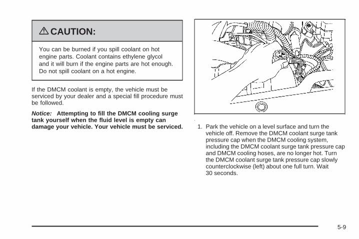
{CAUTION:
You can be burned if you spill coolant on hotengine parts. Coolant contains ethylene glycoland it will burn if the engine parts are hot enough.Do not spill coolant on a hot engine.
If the DMCM coolant is empty, the vehicle must beserviced by your dealer and a special fill procedure mustbe followed.
Notice: Attempting to fill the DMCM cooling surgetank yourself when the fluid level is empty candamage your vehicle. Your vehicle must be serviced. 1. Park the vehicle on a level surface and turn the
vehicle off. Remove the DMCM coolant surge tankpressure cap when the DMCM cooling system,including the DMCM coolant surge tank pressure capand DMCM cooling hoses, are no longer hot. Turnthe DMCM coolant surge tank pressure cap slowlycounterclockwise (left) about one full turn. Wait30 seconds.
5-9

2. Then keep turning the DMCM coolant surge tankpressure cap slowly, and remove it.
3. Add the pre-mixed DEX-COOL™, available at yourdealer/retailer, to the DMCM coolant surge tankuntil the level reaches the FULL COLD mark.
4. Turn the ignition to ON/RUN without starting theengine. The hybrid cooling pumps will run andany trapped air will purge to the surge tank.
5. Add the pre-mixed DEX-COOL™, available at yourdealer/retailer, until the coolant level is maintained atthe FULL COLD mark. This should take no longerthan two minutes of hybrid cooling pump operation.If the level cannot be kept at the FULL COLDlevel, your vehicle may need service. See yourdealer/retailer.
6. Then replace theDMCM coolant surgetank pressure cap.Be sure the pressurecap is hand-tightand fully seated.
Notice: Using tap water, cooling system sealers orconditioners in an attempt to stop coolant leakscan damage the DMCM and engine cooling systems.Never use tap water, cooling system sealers orconditioners in your cooling system.
5-10

Power Steering FluidThe vehicle has electric power steering and does notuse power steering fluid.
Brakes
Brake Fluid
The brake master cylinderreservoir is filled with DOT3 brake fluid. See EngineCompartment Overview onpage 5-4 for the location ofthe reservoir.
There are only two reasons why the brake fluid level inthe reservoir might go down:• The brake fluid level goes down because of normal
brake lining wear. When new linings are installed,the fluid level goes back up.
• A fluid leak in the brake hydraulic system can alsocause a low fluid level. Have the brake hydraulicsystem fixed, since a leak means that sooner or laterthe brakes will not work well.
Do not top off the brake fluid. Adding fluid does notcorrect a leak. If fluid is added when the liningsare worn, there will be too much fluid when new brakelinings are installed. Add or remove brake fluid, asnecessary, only when work is done on the brakehydraulic system.
{CAUTION:
If too much brake fluid is added, it can spill onthe engine and burn, if the engine is hot enough.You or others could be burned, and the vehiclecould be damaged. Add brake fluid only whenwork is done on the brake hydraulic system.See “Checking Brake Fluid” in this section.
When the brake fluid falls to a low level, the brakewarning light comes on. See “Brake System WarningLight” in the owner manual.
Refer to the Maintenance Schedule to determine whento check the brake fluid. See “Scheduled Maintenance”in the owner manual.
5-11

Checking Brake FluidCheck brake fluid by looking at the brake fluid reservoir.See Engine Compartment Overview on page 5-4.
With the engine not running for at least one minute, themaximum fluid level (A) is at the top of the reservoirbody. With the engine running, the fluid level should bein the proper operating range (B) between the MINand MAX marks. If it is not, have the brake hydraulicsystem checked to see if there is a leak.
After work is done on the brake hydraulic system, makesure the level, with the engine running, is in the properoperating range (B) between the MIN and MAX marks.
What to AddUse only new DOT 3 brake fluid from a sealed container.See “Recommended Fluids and Lubricants” in theowner manual.Always clean the brake fluid reservoir cap and the areaaround the cap before removing it. This helps keepdirt from entering the reservoir.
{CAUTION:
With the wrong kind of fluid in the brake hydraulicsystem, the brakes might not work well. This couldcause a crash. Always use the proper brake fluid.
Notice:• Using the wrong fluid can badly damage brake
hydraulic system parts. For example, just a fewdrops of mineral-based oil, such as engine oil, inthe brake hydraulic system can damage brakehydraulic system parts so badly that they willhave to be replaced. Do not let someone put inthe wrong kind of fluid.
• If brake fluid is spilled on the vehicle’s paintedsurfaces, the paint finish can be damaged.Be careful not to spill brake fluid on the vehicle.If you do, wash it off immediately. See “WashingYour Vehicle” in the owner manual.
5-12
Brake WearThis vehicle has disc brakes. Disc brake pads havebuilt-in wear indicators that make a high-pitched warningsound when the brake pads are worn and new padsare needed. The sound can come and go or be heard allthe time the vehicle is moving, except when applyingthe brake pedal firmly.
{CAUTION:
The brake wear warning sound means that soonthe brakes will not work well. That could lead to anaccident. When the brake wear warning sound isheard, have the vehicle serviced.
Notice: Continuing to drive with worn-out brakepads could result in costly brake repair.
Some driving conditions or climates can cause a brakesqueal when the brakes are first applied or lightlyapplied. This does not mean something is wrong withthe brakes.
Properly torqued wheel nuts are necessary to helpprevent brake pulsation. When tires are rotated, inspectbrake pads for wear and evenly tighten wheel nuts inthe proper sequence to torque specifications in“Capacities and Specifications” in the owner manual.
Brake linings should always be replaced as completeaxle sets.
5-13

Brake Pedal TravelSee your dealer/retailer if the brake pedal does notreturn to normal height, or if there is a rapid increase inpedal travel. This could be a sign that brake servicemight be required.
Brake AdjustmentEvery time the brakes are applied, the disc brakesadjust for wear.
Replacing Brake System PartsThe braking system on a vehicle is complex. Its manyparts have to be of top quality and work well together ifthe vehicle is to have really good braking. The vehiclewas designed and tested with top-quality brake parts.When parts of the braking system are replaced — forexample, when the brake linings wear down and newones are installed — be sure to get new approvedreplacement parts. If this is not done, the brakes mightnot work properly. For example, if someone puts inbrake linings that are wrong for the vehicle, the balancebetween the front and rear brakes can change — for theworse. The braking performance expected can change inmany other ways if the wrong replacement brake partsare installed.
5-14

BatteryThis vehicle has a standard 12-volt battery and ahigh-voltage hybrid battery.
When a new standard 12-volt battery is needed, seeyour dealer/retailer for one that has the replacementnumber shown on the original battery’s label.
Only a trained service technician with the properknowledge and tools should inspect, test, or replace thehybrid battery. See your dealer/retailer if the hybridbattery needs service.
If an airbag inflates or the vehicle has been in acrash, the vehicle’s sensing system might commandthe automatic hybrid battery disconnect to open.See Replacing Restraint System Parts After a Crashon page 1-3 for more information.Warning: Battery posts, terminals, and relatedaccessories contain lead and lead compounds,chemicals known to the State of California to causecancer and reproductive harm. Wash hands afterhandling.
Vehicle Storage
{CAUTION:
Batteries have acid that can burn you and gas thatcan explode. You can be badly hurt if you are notcareful. See Jump Starting on page 5-16 for tipson working around a battery without getting hurt.
Infrequent Usage: If the vehicle is driven infrequently,remove the 12-volt battery black, negative (−) cablefrom the battery. This helps keep the battery fromrunning down.
Extended Storage: For extended storage of the vehicle,remove the 12-volt battery black, negative (−) cablefrom the battery or use a battery trickle charger.This helps maintain the charge of the battery over anextended period of time.
Remember to reconnect the battery when ready to drivethe vehicle.
5-15

Jump Starting
{CAUTION:
Personal injury, death, or damage to the vehiclecan result if you try jump starting or using abattery charger on the high voltage hybrid battery.Use only the 12-volt battery for jump starting andcharging.
If the vehicle’s 12-volt battery has run down, you maywant to use another vehicle and some jumper cables tostart your vehicle. Use the following steps to do it safely.
{CAUTION:
Batteries can hurt you. They can be dangerousbecause:
• They contain acid that can burn you.• They contain gas that can explode or ignite.• They contain enough electricity to burn you.
If you do not follow these steps exactly, some orall of these things can hurt you.
Notice: Ignoring these steps could result in costlydamage to the vehicle that would not be coveredby the warranty.
Trying to start the vehicle by pushing or pulling itwill not work, and it could damage the vehicle.
1. Check the other vehicle. It must have a 12-voltbattery with a negative ground system.
5-16

Notice: If the other vehicle’s system is not a 12-voltsystem with a negative ground, both vehicles canbe damaged. Only use vehicles with 12-volt systemswith negative grounds to jump start your vehicle.
2. Get the vehicles close enough so the jumper cablescan reach, but be sure the vehicles are not touchingeach other. It could cause a ground connectionyou do not want. You would not be able to start yourvehicle, and the bad grounding could damage theelectrical systems.To avoid the possibility of the vehicles rolling, setthe parking brake firmly on both vehicles involvedin the jump start procedure. Put the automatictransmission in P (Park) or a manual transmissionin N (Neutral) before setting the parking brake.If you have a four-wheel-drive vehicle, be sure thetransfer case is in a drive gear, not in N (Neutral).
Notice: If you leave the radio or other accessorieson during the jump starting procedure, they could bedamaged. The repairs would not be covered by thewarranty. Always turn off the radio and otheraccessories when jump starting the vehicle.
3. Turn off the ignition on both vehicles. Unplugunnecessary accessories plugged into the cigarettelighter or the accessory power outlets. Turn offthe radio and all the lamps that are not needed.This avoids sparks and helps save both batteries.It could save the radio!
4. Open the hood on the other vehicle and locate thepositive (+) and negative (−) terminal locations onthat vehicle.
5-17
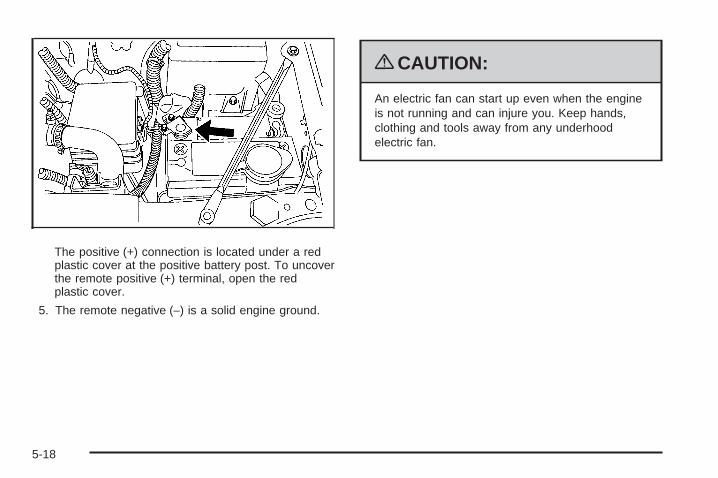
The positive (+) connection is located under a redplastic cover at the positive battery post. To uncoverthe remote positive (+) terminal, open the redplastic cover.
5. The remote negative (−) is a solid engine ground.
{CAUTION:
An electric fan can start up even when the engineis not running and can injure you. Keep hands,clothing and tools away from any underhoodelectric fan.
5-18

{CAUTION:
Using a match near a battery can cause batterygas to explode. People have been hurt doing this,and some have been blinded. Use a flashlight ifyou need more light.
Be sure the battery has enough water. You do notneed to add water to the battery installed in yournew vehicle. But if a battery has filler caps, besure the right amount of fluid is there. If it is low,add water to take care of that first. If you do not,explosive gas could be present.
Battery fluid contains acid that can burn you.Do not get it on you. If you accidentally get it inyour eyes or on your skin, flush the place withwater and get medical help immediately.
{CAUTION:
Fans or other moving engine parts can injure youbadly. Keep your hands away from moving partsonce the engine is running.
6. Check that the jumper cables do not have loose ormissing insulation. If they do, you could get ashock. The vehicles could be damaged too.Before you connect the cables, here are somebasic things you should know. Positive (+) goes topositive (+) or to a remote positive (+) terminalif the vehicle has one. Negative (−) will go toa heavy, unpainted metal engine part or a solidengine ground.Do not connect positive (+) to negative (−) or youwill get a short that would damage the batteryand maybe other parts too. Do not connectthe negative (−) cable to the negative (−) terminalon the dead battery because this can cause sparks.
7. Connect the red positive (+) cable to the positive (+)terminal of the vehicle with the dead battery. Use aremote positive (+) if the vehicle has one.
5-19

8. Do not let the other end touch metal. Connect it tothe positive (+) terminal of the good battery. Use aremote positive (+) if the vehicle has one.
9. Now connect the black negative (−) cable to thenegative (−) terminal of the good battery. Use aremote negative (−) if the vehicle has one.Do not let the other end touch anything until thenext step. The other end of the negative (−) cabledoes not go to the dead battery. It goes to aheavy, unpainted metal engine part or to the remotenegative (−) terminal on the vehicle with the deadbattery.
10. Connect the other end of the negative (−) cable tothe remote negative (−) terminal, on the vehicle withthe dead battery.
11. Now start the vehicle with the good battery and runthe engine for a while.
12. Try to start the vehicle that had the dead battery.If it will not start after a few tries, it probably needsservice.
Notice: If the jumper cables are connected orremoved in the wrong order, electrical shorting mayoccur and damage the vehicle. The repairs wouldnot be covered by the vehicle warranty. Alwaysconnect and remove the jumper cables in the correctorder, making sure that the cables do not toucheach other or other metal.
Jumper Cable Removal
A. Heavy, Unpainted Metal Engine Part or RemoteNegative (−) Terminal
B. Good Battery or Remote Positive (+) and RemoteNegative (−) Terminals
C. Dead Battery or Remote Positive (+) Terminal
To disconnect the jumper cables from both vehicles:
1. Disconnect the black negative (−) cable fromthe vehicle that had the bad battery.
2. Disconnect the black negative (−) cable from thevehicle with the good battery.
5-20

3. Disconnect the red positive (+) cable from thevehicle with the good battery.
4. Disconnect the red positive (+) cable from the othervehicle.
5. Return the remote positive (+) terminal cover to itsoriginal position.
Electrical System
High Voltage Devices and Wiring
{CAUTION:
Exposure to high voltage can cause shock, burns,and even death. The high voltage systems in yourvehicle can only be serviced by technicians withspecial training.
High voltage devices are identified by labels.Do not remove, open, take apart, or modify thesedevices. High voltage cable or wiring has orangecovering. Do not probe, tamper with, cut, or modifyhigh voltage cable or wiring.
Fuses and Circuit BreakersThe wiring circuits in the vehicle are protected fromshort circuits by a combination of fuses, circuit breakersand fusible thermal links. This greatly reduces thechance of fires caused by electrical problems.
Be sure you replace a bad fuse with a new one of theidentical size and rating.
If you ever have a problem on the road and do not havea spare fuse, you can borrow one that has the sameamperage. Just pick some feature of the vehicle thatyou can get along without, like the radio or cigarettelighter, and use its fuse, if it is the correct amperage.Replace it as soon as you can.
The vehicle also has a special fuse in the battery boxfor the 300-volt batteries. If this fuse has failed andneeds to be replaced, the vehicle will be disabled andyou will need to have the vehicle repaired by yourdealer/retailer. Do not attempt to self-service this fuse.
5-21
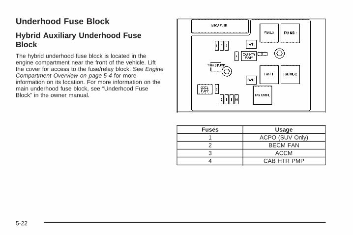
Underhood Fuse Block
Hybrid Auxiliary Underhood FuseBlockThe hybrid underhood fuse block is located in theengine compartment near the front of the vehicle. Liftthe cover for access to the fuse/relay block. See EngineCompartment Overview on page 5-4 for moreinformation on its location. For more information on themain underhood fuse block, see “Underhood FuseBlock” in the owner manual.
Fuses Usage1 ACPO (SUV Only)2 BECM FAN3 ACCM4 CAB HTR PMP
5-22
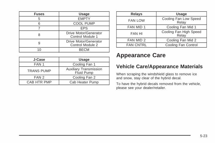
Fuses Usage5 EMPTY6 COOL PUMP7 EPS
8 Drive Motor/GeneratorControl Module 1
9 Drive Motor/GeneratorControl Module 2
10 BECM
J-Case UsageFAN 1 Cooling Fan 1
TRANS PUMP Auxiliary TransmissionFluid Pump
FAN 2 Cooling Fan 2CAB HTR PMP Cab Heater Pump
Relays Usage
FAN LOW Cooling Fan Low SpeedRelay
FAN MID 1 Cooling Fan Mid 1
FAN HI Cooling Fan High SpeedRelay
FAN MID 2 Cooling Fan Mid 2FAN CNTRL Cooling Fan Control
Appearance Care
Vehicle Care/Appearance MaterialsWhen scraping the windshield glass to remove iceand snow, stay clear of the hybrid decal.
To have the hybrid decals removed from the vehicle,please see your dealer/retailer.
5-23

Capacities and Specifications
ApplicationCapacities
English MetricAutomatic Transmission* (Pan Removal and FilterReplacement) 11.5 qt 10.9 L
Cooling SystemDrive Motor Generator Control Module CoolingSystem 2.5 qt 2.4 L
6.0L V8 Engine Cooling System 17.2 qt 16.3 LFuel Tank 26.0 gal 98.4 L*See Automatic Transmission Fluid on page 5-5 for information on checking fluid level.All capacities are approximate. Recheck fluid level after filling.
Engine SpecificationsEngine VIN Code Transmission Spark Plug Gap
6.0L V8 5 Automatic 0.040 in (1.01 mm)
5-24

Maintenance Schedule ......................................6-2Recommended Fluids and Lubricants ................6-2Engine Drive Belt Routing ................................6-2
Section 6 Maintenance Schedule
6-1

Maintenance Schedule
Recommended Fluids andLubricantsFluids identified below are specific to the hybrid vehicleand can be obtained from your dealer/retailer. See theowner manual for the other fluids and lubricantsrecommended for the vehicle.
Usage Fluid/Lubricant
DriveMotor/GeneratorControl Module
(DMCM)Cooling System
Always use the pre-mixed50/50 mixture of de-ionized waterand DEX-COOL® (silicate-free)coolant available at yourdealer/retailer. See DriveMotor/Generator Control Module(DMCM) Cooling Systemon page 5-6.
Engine Drive Belt Routing
6-2
AAntilock Brake System (ABS)
Warning Light ............................................... 3-7Appearance Care
Vehicle Care/Appearance Materials ................ 5-23Audio System(s)
Navigation/Radio System .............................. 3-14Automatic Transmission, Fluid ............................ 5-5
BBattery .......................................................... 5-15Belt Routing, Engine ......................................... 6-2Brake Fluid .................................................... 5-11Brakes .......................................................... 5-11
Regenerative Braking ................................... 2-18System Warning Light .................................... 3-5
CCanadian Owners ................................................ iiCapacities and Specifications ............................ 5-24Charging System Light ...................................... 3-4Climate Controls ............................................... 3-2Coolant
Engine Temperature Gage .............................. 3-8Coolant Surge Tank Pressure Cap, (DMCM) ......... 5-6Cooling System, (DMCM) .................................. 5-6Covers
ATonneau .............................................. 2-2, 2-7
DDrive Motor/Generator Control Module (DMCM)
Coolant Surge Tank Pressure Cap ................... 5-6Drive Motor/Generator Control Module (DMCM)
Cooling System ............................................. 5-6Driver Information Center (DIC) ......................... 3-12
Warnings and Messages ............................... 3-12
1

EEngine
Compartment Overview .................................. 5-4Coolant Temperature Gage ............................. 3-8Drive Belt Routing ......................................... 6-2
FFluid, Power Steering ...................................... 5-11Fuel
Gage ......................................................... 3-11Fuel Economy Gage ......................................... 3-5
GGage
Oil Pressure ................................................. 3-8Tachometer .................................................. 3-4
GagesEngine Coolant Temperature ........................... 3-8Fuel .......................................................... 3-11Fuel Economy .............................................. 3-5
HHigh Voltage Devices and Wiring ........................ 5-3
IInstrument Panel Cluster ................................... 3-3Introduction ......................................................... ii
JJump Starting ................................................. 5-16
LLights
Antilock Brake System (ABS) Warning .............. 3-7Brake System Warning ................................... 3-5Charging System ........................................... 3-4Oil Pressure ............................................... 3-10StabiliTrak® Indicator ..................................... 3-7
2

MMaintenance Schedule
Recommended Fluids and Lubricants ............... 6-2Manual, How to Use ........................................... iii
NNavigation/Radio System .................................. 3-14
OOil
Pressure Light ............................................. 3-10Oil Pressure Gage ............................................ 3-8Owners, Canadian ............................................... ii
PPower Steering Fluid ....................................... 5-11
RRadios
Navigation/Radio System .............................. 3-14Rear Seat Operation ......................................... 1-2Recommended Fluids and Lubricants .................. 6-2Regenerative Braking ...................................... 2-18Restraint System Check
Replacing Restraint System PartsAfter a Crash ............................................ 1-3
Running the Vehicle While Parked ..................... 2-18
3

SSeats
Rear Seat Operation ...................................... 1-2Service, Doing Your Own Work .......................... 5-2Specifications and Capacities ............................ 5-24StabiliTrak® Indicator Light ................................. 3-7Starting Your Vehicle ....................................... 2-12Steering
Fluid, Power ............................................... 5-11
TTachometer ...................................................... 3-4Tonneau Cover .......................................... 2-2, 2-7Towing
Towing Your Vehicle ...................................... 4-2Trailer .......................................................... 4-2
Transmission, Automatic Fluid ............................. 5-5
VVehicle
Running While Parked .................................. 2-18Voltage Devices, and Wiring ............................... 5-3
WWiring, High Voltage Devices ............................. 5-3
4