2008/6/1 “book” page xxviii - nc state universityrsmith/chapter1.pdf2008/6/1 page 1 ... −...
TRANSCRIPT

“book”2008/6/1page xxviii
i
i
i
i
i
i
i
i

“book”2008/6/1page 1
i
i
i
i
i
i
i
i
Chapter 1
Smart Material
Applications
1.1 Smart Material Systems
Increased demands for high performance control design in combination with recentadvances in material science have produced a class of systems termed smart, in-telligent or adaptive systems. While subtle differences may be associated with theindividual terms, smart systems are generally defined as ensembles whose dynamicscan be monitored or modified by distributed sensors and actuators, in accordancewith an integrated control law, to accommodate time-varying exogenous inputs orchanging environmental conditions. Specific choices for the actuators, sensors andcontrol laws are dictated by the design requirements for the system.
For aeronautic and aerospace systems, control transducers must be lightweightand should typically have minimal effect on the passive system dynamics. Further-more, actuators must provide the required strain or force inputs using the availablepower supplies which, in certain aerospace structures, may require the scavengingof power from other components in the system. Restrictions on size and weight alsodictate that transducers in some regimes must be capable of multiple roles. For ex-ample, transducers which monitor and control vibrations in an aircraft fuselage mayalso be required to act as inputs and sensors for health monitoring or nondestructiveevaluation of the structure. The limitations on the mass and size of transducersare often relaxed in industrial applications but output requirements may be morestringent. For example, magnetostrictive transducers employed in the cutting headof a milling machine can weigh several pounds but are required to achieve cuttingtolerances on the order of 1 µm while operating in kilohertz regimes.
Actuators and sensors comprised of smart or active materials can meet many ofthese criteria. Like the definition for smart systems, the definitions of smart or activematerials can vary between fields. We define active actuator materials as thosewhich convert electrical, magnetic or thermal energy to mechanical energy whereassensor effects are provided by the opposite conversion of energy. In a similar vein,we define smart material transducers as fully integrated devices which employ smartmaterials in concert with the hardware required to generate the electric, magnetic,thermal, or stress fields required for actuation or measured during sensing. The
1
“book”2008/6/1page 2
i
i
i
i
i
i
i
i
2 Chapter 1. Smart Material Applications
difference between the constituent smart materials and smart material transducersis illustrated by a magnetostrictive transducer design presently employed for highaccuracy, high speed industrial milling. As detailed in Section 1.3, a Terfenol-D rodprovides the input/diagnostic capabilities whereas the full transducer is additionallycomprised of a prestress mechanism, wound-wire solenoid and surrounding magnetwhich are used to generate or measure magnetic fields and shape the flux for optimalactuator/sensor design.
A review of the literature or consideration of conference programs in 1990would reveal that smart materials research at that time was focused primarily onpiezoelectric materials with emerging emphasis on shape memory alloys (SMA),magnetostrictive compounds, electrorheological (ER) and magnetorheological (MR)fluids, PVDF films, polymer gels and fiber optic sensors. Whereas the nonlinearand potentially hysteretic constitutive behavior of most of these compounds wasrecognized and being quantified, the majority of models and model-based controldesigns for systems utilizing smart material actuators and sensors were linear.
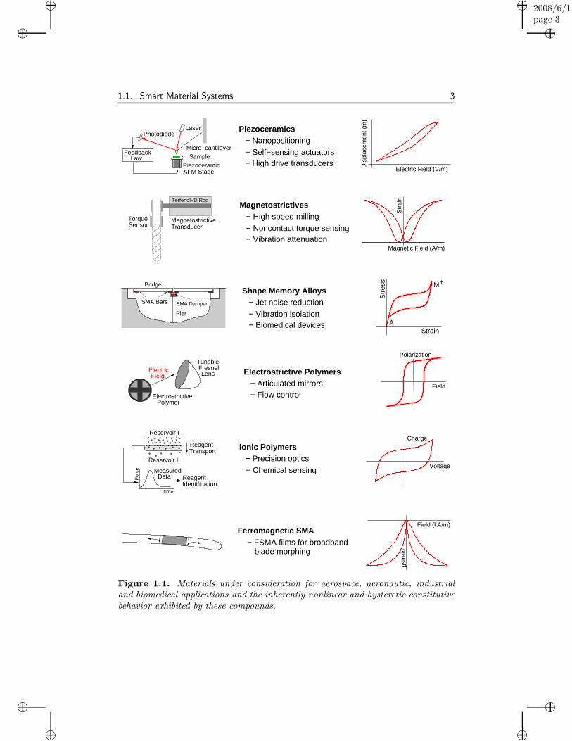
In the subsequent time period, research on all of these materials has burgeonedand advances in materials science have produced compounds such as ionic polymers,electrostrictive polymers, and ferromagnetic shape memory alloys (FSMA) whichhave the potential for providing unique transducer capabilities for high performanceaerospace, aeronautic, automotive, industrial and biomedical applications. Fig-ure 1.1 summarizes a number of present and projected applications and the materialbehavior which must be accommodated when designing smart material transducersfor these systems.
Piezoelectric materials and transducers are widely considered for smart struc-ture design due to the fact that they are lightweight and compact, relatively inex-pensive, and exhibit moderately linear field-strain relations at low drive levels. Theyalso exhibit broadband drive capabilities and very high set point accuracy which,to date, has made them the material of choice for stages in nanopositioners. Fi-nally, the converse and direct piezoelectric effects provide these materials with bothactuator and sensor capabilities. Due to the noncentrosymmetric nature of piezo-electric materials, they exhibit hysteresis and constitutive nonlinearities at all drivelevels. For low input regimes, these deleterious effects can typically be mitigatedthrough feedback mechanisms. In high drive regimes, however, it is necessary toemploy charge or current control, or models and control designs which incorporatehysteresis to achieve the tolerances required for nanopositioning or high accuracytracking.
In certain applications, electrostrictive transducers constructed from relaxorferroelectric materials are advantageous over piezoelectric materials due to the factthat they exhibit minimal hysteresis when employed in the diffuse transition regionnear the material’s bulk Curie point. This makes them advantageous in applicationsranging from sonar transduction to deformable mirror design. Unlike piezoelectricmaterials, electrostrictive compounds are not poled and hence exhibit few agingeffects. However, their highly temperature-dependent and nonlinear saturation be-havior must be accommodated when designing control systems which incorporatethese compounds.
“book”2008/6/1page 3
i
i
i
i
i
i
i
i
1.1. Smart Material Systems 3
Ferromagnetic SMA
− High speed millingMagnetostrictives
µstr
ain
Field (kA/m)
− Chemical sensing
Ionic Polymers− Precision optics
Bridge
Piezoceramics− Nanopositioning− Self−sensing actuators
Electric Field (V/m)Dis
plac
emen
t (m
)
− High drive transducers
− Biomedical devices
− Jet noise reductionShape Memory Alloys
− Vibration isolation
Polarization
Field
Electrostrictive Polymers
− Flow control− Articulated mirrors
M+
A
Str
ain
− Noncontact torque sensing− Vibration attenuation
Magnetic Field (A/m)
blade morphing
IdentificationReagent
MeasuredData
Reservoir II
Reservoir I
Time
ReagentTransport
For
ce
Voltage
Charge
− FSMA films for broadband
Pier
SMA DamperSMA Bars
Str
ess
Strain
Micro−cantileverSample
AFM StagePiezoceramic
ElectrostrictivePolymer
Field LensFresnelTunable
Electric
LawFeedback
PhotodiodeLaser
MagnetostrictiveTransducer
TorqueSensor
Terfenol−D Rod
Figure 1.1. Materials under consideration for aerospace, aeronautic, industrialand biomedical applications and the inherently nonlinear and hysteretic constitutivebehavior exhibited by these compounds.
“book”2008/6/1page 4
i
i
i
i
i
i
i
i
4 Chapter 1. Smart Material Applications
The magnetic analogue of electrostrictive compounds are magnetostrictive ma-terials which convert magnetic energy into mechanical energy and conversely. Dueto the circuits required to generate the driving magnetic fields, transducers whichutilize magnetostrictive cores are larger and more massive than piezoelectric or elec-trostrictive patches. The ruggedness, giant forces, and moderate strains generatedby the transducers, however, make them advantageous in certain industrial sys-tems — such as transducers for high speed milling — and as material propertiesand transducer designs are refined, the scope of their application should rapidly in-crease. From a modeling and control perspective, the nonlinearities and hysteresisinherent to the materials at moderate to high drive levels must be accommodatedbefore the materials can be utilized to their full potential.
Shape memory alloys (SMA) are being increasingly considered for civil, aero-nautic, aerospace and industrial applications which require significant passive damp-ing or utilize the high work output densities exhibited by the materials. Becausethe energy dissipated by the materials is proportional to the area of the hysteresisloop, pseudoelastic operating regimes which maximize hysteresis are required whenemploying SMA as tendons to attenuate earthquake or wind-induced vibrationsin buildings or as fibers to eliminate vibrations in articulated antennas or mem-brane mirrors. The utilization of temperature-induced phase transitions to provideactuator capabilities is under intense investigation in the context of microelectrome-chanical systems (MEMS), thin film SMAs, and microactuator applications sincesurface area to volume ratios in these geometries promote rapid cooling and hencehigher frequency drive capabilities.
The goal of obtaining higher drive frequencies while maintaining high workdensities has motivated the development of ferromagnetic shape memory alloy(FSMA) materials which rely on magnetic field-induced phase transitions to provideactuator inputs. Initial investigations focused on FSMA films have demonstrateddrive frequencies on the order of 5 kHz with potential for reaching 10–15 kHz ascompared with SMA films which presently have maximum operating frequencies onthe order of 100 Hz.
Electrostrictive polymers including PVDF, polyimides and polymeric elas-tomers are lightweight, highly flexible and malleable, and provide both actuatorand sensor capabilities. For these reasons, they are being investigated for use asremote lens cleaners for aerospace missions, acoustic pressure sensors, flow controlactuators, synthetic jets, artificial muscles for robotic units, backing material formembrane mirrors and tunable lenses, and actuator implants to stimulate tissueand bone growth. However, their success is predicated on the quantification of con-stitutive nonlinearities and hysteresis in a manner which promotes real-time controldesign.
Ionic polymers differ from PVDF, polyimides and polymeric elastomers in thatelectromechanical coupling in ionic polymers is produced through the transport ofcharged and uncharged ions within the polymer matrix. This provides them withboth mechanical actuator and sensor capabilities and the potential for chemical andbiological sensing.
The design of smart structures which utilize these materials requires boththe characterization of their constitutive properties and the development of cou-

“book”2008/6/1page 5
i
i
i
i
i
i
i
i
1.1. Smart Material Systems 5
P
NoiseSensor
y(ii)
(i)
(iii)
r
Ku
Ku
Ku
u+d
u+d
(ii) Linear control − hysteresis model
(i) Linear control − linear model
(iii) Nonlinear control − linear model
Figure 1.2. (i) Linear robust control design employing a linear model. (ii) Linearrobust control design utilizing a model-based inverse filter for hysteretic transducers,and (iii) Nonlinear control design employing a linear model for hysteretic transduc-ers.
pled models which quantify their interaction with underlying systems. Control lawsmust be compatible with the properties of the sensors and actuators as well as themechanisms through which they interact with the system. For example, a num-ber of the previously mentioned actuators yield unbounded (discontinuous) inputoperators in the mathematical formulation of the control problem. The extensionof control theories to this regime has been been completed in certain applicationsbut is lacking in general. Moreover, all of the active materials exhibit nonlineardynamics and hysteresis at high drive levels. This must be incorporated in boththe models and control methods before the materials can be utilized to their fullcapability in smart structure design. As depicted in Figure 1.2, control design fornonlinear and hysteretic transducers yields a hierarchy of algorithms ranging fromlinear control algorithms utilizing approximate inverse models to fully nonlinearcontrol laws which directly accommodate the hysteresis and constitutive nonlinear-ities inherent to the transducer materials. While aspects of the nonlinear designshave been addressed, the state of the theory lags far behind that for the linear case.
Because the dynamics of a smart structure are dependent upon the attributesof the constituent active materials, it is necessary to consider the development oflinear, nonlinear and hysteretic constitutive relations, their incorporation in coupledsystem models, numerical approximation of these models, and subsequent controldesign in a concerted manner. This facilitates the development of models amenableto control design, and the formulation of control laws which are compatible withphysical attributes of active sensor and actuator materials. By incorporating knownphysics into the models, the degree to which control laws must attenuate unmod-eled dynamics is reduced thus improving their performance in high performanceapplications utilizing smart material transducers.

“book”2008/6/1page 6
i
i
i
i
i
i
i
i
6 Chapter 1. Smart Material Applications
1.2 Piezoelectric and Electrostrictive Applications
1.2.1 History
To illustrate the evolution of piezoelectric materials toward smart material applica-tions, we summarize briefly their history. A detailed treatment of this history canbe found in the classic texts [73, 234,243,325].
Piezoelectricity, which literally means “pressure electricity” from the Greekword “piezo” for pressure, was discovered by Pierre and Jacque Curie in 1880 whilePierre was investigating the relationship between pyroelectricity and certain crystalsymmetries. In studies initially focused on tourmaline and later extended to quartz,cane sugar, and Rochelle salt, the Curie brothers were able to demonstrate thegeneration of electric charge in response to applied pressure or stresses. This is thedirect piezoelectric effect which, in present materials, can produce voltages rangingfrom a fraction of a volt to several thousand volts. The converse effect, whichconstitutes the generation of strains or displacements in the material in responseto applied fields, was subsequently justified using thermodynamic principles. Botheffects are due to the noncentrosymmetric nature of certain ceramics, polymers andbiological systems and it is this property which also produces the switching-inducedhysteresis and constitutive nonlinearities inherent to ferroelectric and piezoelectricmaterials.
An initial linear characterization of the electromechanical properties of piezo-electric materials was published in 1910 in Voigt’s Lehrbuch der Kristallphysik [500]which established the notation still employed in linear piezoelectric models. In 1916,Paul Langevin developed a transducer comprised of a quartz crystal sandwiched be-tween two metal plates which functioned as an ultrasonic submarine detector [326].Sound waves in water were produced when the quartz was used to oscillate theplates and a second quartz device was employed to measure rebounding waves. Thedistance to the reflecting source was computed from the time between the emittedand received acoustic signals. This was a forerunner of modern sonar and exempli-fies the dual use of actuator/sensor capabilities exploited in present smart materialdesigns.
From 1916 through the 1950’s, research focused both on material developmentand the use of new materials to create novel technologies, with a number of thecontributions made by Walter Cady. During this time period, the KDP (potassiumdihydrogen phosphate) family was discovered in 1940 and the first piezoceramiccompound BaTiO3 (barium titanate) was produced. BaTiO3 was the first of theperovskite family of piezoceramic materials to receive widespread usage and it servedas a precursor to lead zirconate titanate (PZT) and lead magnesium niobate (PMN)— discovered in the 1950’s — which presently are among the most widely employedferroelectric compounds due to their high dielectric and piezoelectric strengths,moderate costs, and broad range of operating temperatures. The technologies basedon these materials during this time period included the development of crystalphonograph pickups, microphones, wave filters for multichannel telephone design,and radio communication advances based on quartz crystals — over 50 millionquartz crystals were employed by the United States during WWII. As detailed

“book”2008/6/1page 7
i
i
i
i
i
i
i
i
1.2. Piezoelectric and Electrostrictive Applications 7
by Mason [325, 326], a substantial portion of both the material development andinvention of technologies based on these materials was performed during this periodat Bell Laboratories.
During the 1960’s and 1970’s, research focused both on the development ofnovel technologies utilizing BaTiO3, PZT and PMN, and the investigation of newcompounds to eliminate limitations due to the rigid nature of piezoceramics. Thislatter goal was achieved in 1969 by Kawai when he discovered that polyvinylidenefluoride (PVDF) had piezoelectric coefficients approximately ten times larger thanpreviously discovered polymers [261]. PVDF has subsequently been widely consid-ered for both sensor and actuator applications and to date has been the most widelyused piezoelectric polymer.
From 1980 through the present time, research on both material developmentand the development of high performance aerospace, aeronautic, industrial andbiomedical applications, based on ferroelectric and piezoelectric compounds, bur-geoned. Materials research has focused on the development of single crystal materi-als which exhibit strains approaching 1% while extensive polymer research led to theproduction of polyimides [337], elastomeric and amorphous polymers [209,468] andbiological polymers [169, 170]. Applications utilizing the direct piezoelectric effectinclude gas igniters, accelerometers employing PZT disks which play a central rolein automotive airbag systems, and mode-specific sensors based on geometrically-configured PVDF films. Commercial actuator applications include dot matrixprinter heads, auto-tracking devices for VCR’s which avoid magnetic noise, shuttermechanisms for cameras, and the PZT-based TEMS (Toyota Electronic ModulatedSuspension) which was produced in 1989 to augment shock absorber capabilities(see [489] and included references). Piezo-actuators have also played a pivotal rolein nanotechnology starting with their use as positioning elements in scanning tun-neling microscopes (STM) in 1982 and atomic force microscopes (AFM) in 1985and continuing to the present in essentially all nanopositioner applications.
In addition to the development of novel materials and technologies which hasoccurred in the last 20 years, three research areas have become increasingly impor-tant — (i) the development of nonlinear and hysteretic constitutive relations andconstruction of fully integrated system models based on linear and nonlinear consti-tutive relations, (ii) full and reduced-order approximation techniques for discretizingthese system models, and (iii) model-based control designs which incorporate knownphysics to achieve the stringent design criteria dictated by present and projected ap-plications. Furthermore, it has been increasingly recognized that these componentsshould ideally be investigated in concert to achieve the novel design capabilitiesprovided by these materials.
1.2.2 Prototypical Applications
The breadth of systems employing piezoelectric transducers precludes a survey andwe instead focus on several prototypical applications which illustrate issues to beaddressed when developing constitutive and system models, full and reduced-orderapproximation techniques and model-based control designs.

“book”2008/6/1page 8
i
i
i
i
i
i
i
i
8 Chapter 1. Smart Material Applications
Structural Shape Modification
Many of the initial applications utilizing both the sensing and actuating ca-pabilities of piezoelectric materials focused on structural shape modification or vi-bration control. This provided both a testbed for theoretical development and asource of emerging technologies.
To illustrate a theoretical prototype, consider the thin beam with surface-mounted piezoceramic patches depicted in Figure 1.3. Through the input of dia-metrically out-of-phase voltages to the patches, bending moments are created inthe beam thus producing transverse displacements. This provides actuator capa-bilities for the configuration. Sensor capabilities are provided by the direct piezo-electric effect in which stresses in the patch produce charges and correspondingvoltages. A truly integrated smart structure utilizes either self-sensing actuators orsensor-actuator pairs to provide the observations and inputs required for vibrationattenuation [11, 103,135].
Theoretical issues which have been investigated in this context are the de-velopment of linear and nonlinear constitutive relations which quantify the patchinputs to the structure as well as the passive effects contributed by the patch mate-rial to the structural dynamics. This configuration provides a natural prototype forinvestigating numerical approximation techniques since beam models are sufficientlycomplex to encompass a number of issues associated with more complex structuresbut avoid difficulties associated with shear locking and 2-D analysis which make theapproximation of plate and shell models difficult. From the perspective of controldesign, this has been an important prototype for investigating the ramificationsof the unbounded (discontinuous) control input operators which result from thepiecewise input regions provided by the patches.
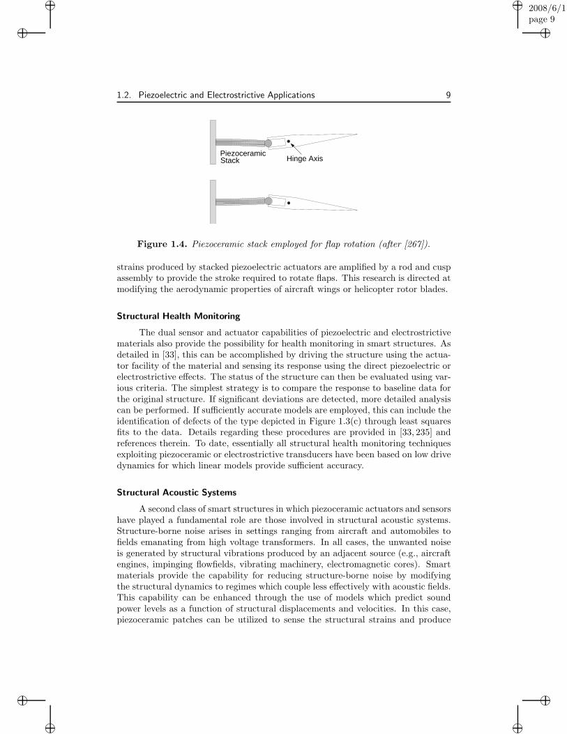
A technological prototype illustrating the use of piezoceramic patches to pro-vide shape or structural changes to enhance system performance is illustrated bythe flap assembly from [267] which is depicted in Figure 1.4. In this design, the
(a)
(c)
(b)
Figure 1.3. (a) Thin beam with surface-mounted piezoceramic patches. (b) Bend-ing moments generated by out-of-phase voltages to the patches. (c) Identification ofstructural damage using the dual actuator/sensor capabilities of PZT transducers.
“book”2008/6/1page 9
i
i
i
i
i
i
i
i
1.2. Piezoelectric and Electrostrictive Applications 9
PiezoceramicStack Hinge Axis
Figure 1.4. Piezoceramic stack employed for flap rotation (after [267]).
strains produced by stacked piezoelectric actuators are amplified by a rod and cuspassembly to provide the stroke required to rotate flaps. This research is directed atmodifying the aerodynamic properties of aircraft wings or helicopter rotor blades.
Structural Health Monitoring
The dual sensor and actuator capabilities of piezoelectric and electrostrictivematerials also provide the possibility for health monitoring in smart structures. Asdetailed in [33], this can be accomplished by driving the structure using the actua-tor facility of the material and sensing its response using the direct piezoelectric orelectrostrictive effects. The status of the structure can then be evaluated using var-ious criteria. The simplest strategy is to compare the response to baseline data forthe original structure. If significant deviations are detected, more detailed analysiscan be performed. If sufficiently accurate models are employed, this can include theidentification of defects of the type depicted in Figure 1.3(c) through least squaresfits to the data. Details regarding these procedures are provided in [33, 235] andreferences therein. To date, essentially all structural health monitoring techniquesexploiting piezoceramic or electrostrictive transducers have been based on low drivedynamics for which linear models provide sufficient accuracy.
Structural Acoustic Systems
A second class of smart structures in which piezoceramic actuators and sensorshave played a fundamental role are those involved in structural acoustic systems.Structure-borne noise arises in settings ranging from aircraft and automobiles tofields emanating from high voltage transformers. In all cases, the unwanted noiseis generated by structural vibrations produced by an adjacent source (e.g., aircraftengines, impinging flowfields, vibrating machinery, electromagnetic cores). Smartmaterials provide the capability for reducing structure-borne noise by modifyingthe structural dynamics to regimes which couple less effectively with acoustic fields.This capability can be enhanced through the use of models which predict soundpower levels as a function of structural displacements and velocities. In this case,piezoceramic patches can be utilized to sense the structural strains and produce
“book”2008/6/1page 10
i
i
i
i
i
i
i
i
10 Chapter 1. Smart Material Applications
bending moments in accordance with a structural acoustic model-based controllaw [99].
The sound pressure levels originally considered in aircraft, automotive andindustrial systems were typically linear, and linear PZT models were employed forcharacterization and control design. As noted in [99], feedforward methods arecurrently employed for many structural acoustic applications. Because these tech-niques rely on superposition principles, they are inherently linear and hence requireeither linear models or linear filtering techniques such as inverse compensation.
Current and future structural acoustic applications are beginning to focus onregimes which are highly nonlinear and will require the development of nonlinearmodels and control techniques. For example, the sound pressure levels produced ina space launch vehicle payload fairing during liftoff or impinging on an aircraft bayat supersonic speeds can exceed 150 dB [149, 404, 513]. Smart materials employedin these applications will quite likely be operating in highly nonlinear ranges thusnecessitating the use of nonlinear constitutive and hysteresis models of the typedeveloped in Chapter 2.
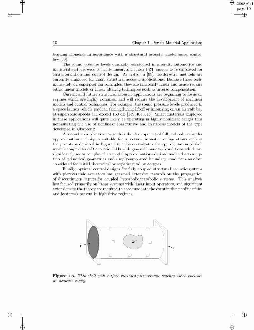
A second area of active research is the development of full and reduced-orderapproximation techniques suitable for structural acoustic configurations such asthe prototype depicted in Figure 1.5. This necessitates the approximation of shellmodels coupled to 3-D acoustic fields with general boundary conditions which aresignificantly more complex than modal approximations derived under the assump-tion of cylindrical geometries and simply-supported boundary conditions as oftenconsidered for initial theoretical or experimental prototypes.
Finally, optimal control designs for fully coupled structural acoustic systemswith piezoceramic actuators has spawned extensive research on the propagationof discontinuous inputs for coupled hyperbolic/parabolic systems. This analysishas focused primarily on linear systems with linear input operators, and significantextensions to the theory are required to accommodate the constitutive nonlinearitiesand hysteresis present in high drive regimes.
Γ(t)Ω
Γ
Figure 1.5. Thin shell with surface-mounted piezoceramic patches which enclosesan acoustic cavity.

“book”2008/6/1page 11
i
i
i
i
i
i
i
i
1.2. Piezoelectric and Electrostrictive Applications 11
RAINBOW and THUNDER Transducers
A number of transducer designs have been developed, or are under investiga-tion, to augment strain, force, or drive level capabilities of the constituent piezoelec-tric or electrostrictive materials through curvature enhancement, prestress augmen-tation, or geometrical coupling with surrounding materials or strain enhancementmechanisms. This includes RAINBOW (Reduced And InterNally Biased OxideWafer) [200, 201, 233, 294], THUNDER (THin layered UNimorph Driver and sEn-soR) [348,350,470,509], and Lipca [349].
To illustrate, consider the THUNDER design depicted in Figure 1.6(a). Asdetailed in [77, 231, 350], present THUNDER designs are typically comprised ofa piezoceramic wafer, a metallic backing layer, hot melt adhesive layers, and op-tional metallic top layers. During the manufacturing process, the assemblage isheated under pressure to temperatures in the proximity of the Curie point for PZTand then cooled to room temperature. During the cooling phase, the adhesivesolidifies and internal stresses are developed in the constituent materials due todiffering thermal properties. This produces the characteristic curved shape andprestresses which align dipoles to enhance strains generated by an applied field.Additionally, the backing layer provides robustness which allows the generation oflarge strains without damaging the transducer. The combination of robustness andcurvature/prestress enhancement provides THUNDER with sufficiently large dis-placement capabilities to give great potential for applications including high speedvalve design, synthetic jets for flow control, shape modification in space structuressuch as configurable mirrors, configurable shape modification of an airfoil to controlflow characteristics, and linear motor design for microrobotics [372].
(a)
−20 −10 0 10 20−10
−5
0
5
10
15
20
Field (KV/cm)
Dis
pla
cem
en
t (m
ils)
(c)
Synthetic Jets
(b) THUNDER
Figure 1.6. (a) THUNDER transducer considered for (b) flow control and syntheticjet design. (c) Stress-dependent electromechanical behavior exhibited by THUNDERtransducers.
“book”2008/6/1page 12
i
i
i
i
i
i
i
i
12 Chapter 1. Smart Material Applications
However, high drive levels in combination with stress-enhanced electromechan-ical coupling yield field-displacement relations which are nonlinear, hysteretic, andasymmetric as shown in Figure 1.6(c). This necessitates the development of non-linear constitutive relations which incorporate both hysteresis and full electrome-chanical coupling, the construction and approximation of system models based onthese constitutive relations, and the investigation of commensurate control designsto achieve the high drive capabilities provided by THUNDER.
Flextensional Design, Hybrid Transducers, and Ultrasonic Motors
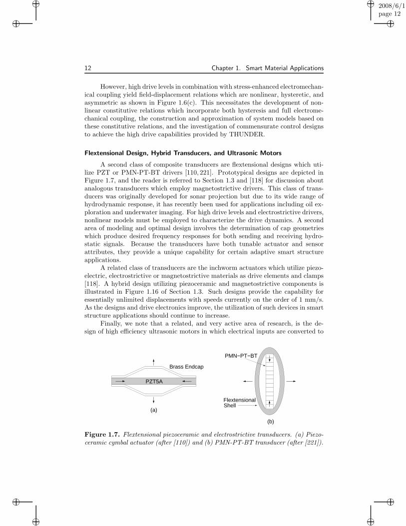
A second class of composite transducers are flextensional designs which uti-lize PZT or PMN-PT-BT drivers [110, 221]. Prototypical designs are depicted inFigure 1.7, and the reader is referred to Section 1.3 and [118] for discussion aboutanalogous transducers which employ magnetostrictive drivers. This class of trans-ducers was originally developed for sonar projection but due to its wide range ofhydrodynamic response, it has recently been used for applications including oil ex-ploration and underwater imaging. For high drive levels and electrostrictive drivers,nonlinear models must be employed to characterize the drive dynamics. A secondarea of modeling and optimal design involves the determination of cap geometrieswhich produce desired frequency responses for both sending and receiving hydro-static signals. Because the transducers have both tunable actuator and sensorattributes, they provide a unique capability for certain adaptive smart structureapplications.
A related class of transducers are the inchworm actuators which utilize piezo-electric, electrostrictive or magnetostrictive materials as drive elements and clamps[118]. A hybrid design utilizing piezoceramic and magnetostrictive components isillustrated in Figure 1.16 of Section 1.3. Such designs provide the capability foressentially unlimited displacements with speeds currently on the order of 1 mm/s.As the designs and drive electronics improve, the utilization of such devices in smartstructure applications should continue to increase.
Finally, we note that a related, and very active area of research, is the de-sign of high efficiency ultrasonic motors in which electrical inputs are converted to
(a)
Brass Endcap
(b)
FlextensionalShell
PMN−PT−BT
PZT5A
Figure 1.7. Flextensional piezoceramic and electrostrictive transducers. (a) Piezo-ceramic cymbal actuator (after [110]) and (b) PMN-PT-BT transducer (after [221]).

“book”2008/6/1page 13
i
i
i
i
i
i
i
i
1.2. Piezoelectric and Electrostrictive Applications 13
mechanical outputs using piezoelectric actuators. This provides the potential foreliminating the variability and aging associated with conventional hydraulic andelectromagnetic motors. Rather than provide a partial summary of this research,we direct the reader to the work of Uchino [489] and references therein.
Nanopositioning Stages
Since the inception of the scanning tunneling microscope (STM) in 1982 andatomic force microscope (AFM) in 1985 [206], piezoceramic actuators have playeda fundamental role in the design of stages for micro- and nano-positioning. Thisrole has continually expanded as instruments have evolved to achieve increasinglystringent speed and accuracy specifications, and PZT-based stages are considered forapplications ranging from nanoconstruction to the development of nuclear magneticresonance microscopes (NMRM) with the goal of detecting single electron spins[398,516].
To illustrate issues associated with both device design and subsequent modeland control development, consider the prototypical AFM design depicted in Fig-ure 1.8 and detailed in [206, 445, 446]. To ascertain the 3-D surface structure of asample, the sample is moved laterally along an x-y grid using a PZT transducerand displacements in an adjacent microcantilever are monitored using a photodiode.Corresponding forces are determined via Hooke’s law and a feedback law is used tocompute z-displacements — also provided by a PZT actuator — which maintainconstant forces. A complete scan in this manner provides a surface image of thecompound as depicted in Figure 1.8(b).
The degree of accuracy provided by the PZT actuators when laterally andvertically positioning the sample is crucial to the resolution of the final image. Tworepresentative transducer designs are illustrated in Figure 1.9. The first is com-prised of a stage in which d33 inputs from PZT rods are used to provide lateral
Photodiode
Piezoceramic StageSample
Micro−cantilever
Laser
FeedbackLaw
xy
z
x
Micro−cantilever
z
(a) (b)
Figure 1.8. (a) Configuration of a prototypical AFM; (b) Surface image determinedby one lateral sweep.
“book”2008/6/1page 14
i
i
i
i
i
i
i
i
14 Chapter 1. Smart Material Applications
arm
y−piezo
arm
y−LVDT PositionerSample
x−LVDT
x−piezo
z actuator
x−y actuator
(a) (b)
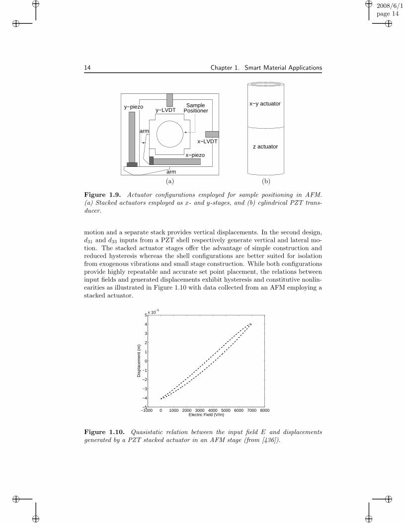
Figure 1.9. Actuator configurations employed for sample positioning in AFM.(a) Stacked actuators employed as x- and y-stages, and (b) cylindrical PZT trans-ducer.
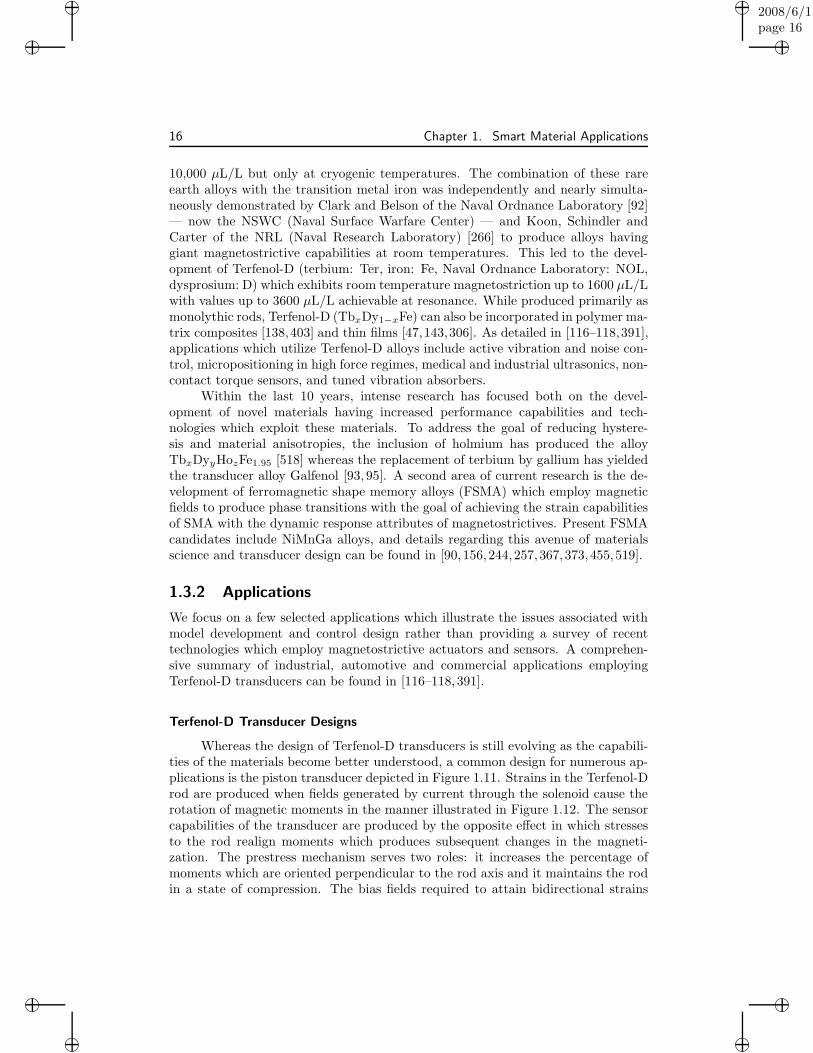
motion and a separate stack provides vertical displacements. In the second design,d31 and d33 inputs from a PZT shell respectively generate vertical and lateral mo-tion. The stacked actuator stages offer the advantage of simple construction andreduced hysteresis whereas the shell configurations are better suited for isolationfrom exogenous vibrations and small stage construction. While both configurationsprovide highly repeatable and accurate set point placement, the relations betweeninput fields and generated displacements exhibit hysteresis and constitutive nonlin-earities as illustrated in Figure 1.10 with data collected from an AFM employing astacked actuator.
−1000 0 1000 2000 3000 4000 5000 6000 7000 8000−5
−4
−3
−2
−1
0
1
2
3
4
5x 10
−5
Electric Field (V/m)
Dis
plac
emen
t (m
)
Figure 1.10. Quasistatic relation between the input field E and displacementsgenerated by a PZT stacked actuator in an AFM stage (from [436]).

“book”2008/6/1page 15
i
i
i
i
i
i
i
i
1.3. Magnetostrictive Transducers 15
For certain drive regimes, the hysteresis and constitutive nonlinearities can bemitigated through either the drive electronics or feedback loops incorporated in thesoftware. As detailed in [315, 316], the use of charge or current controlled ampli-fiers can essentially eliminate hysteresis. However, this mode of operation can beprohibitively expensive when compared with the more commonly employed voltage-controlled amplifiers, and current control is ineffective if maintaining DC offsets asis the case when the x-stage of an AFM is held in a fixed position while a sweep isperformed with the y-stage. For low scan rates, PID or robust control designs canbe employed to accommodate hysteresis [108,401]. However, at the high scan ratesrequired for real-time product diagnostics (e.g., semiconductor chips) or monitoringof biological processes (e.g., protein unfolding), increasing noise-to-data ratios anddiminishing high-pass characteristics of control filters preclude a sole reliance onfeedback laws to eliminate hysteresis. This motivates the development of controldesigns which incorporate and approximately compensate for hysteresis throughmodel inverses employed either in feedback or feedforward loops. The models andinverse models must fully accommodate transient dynamics and be applicable toeither the rod or shell geometries employed in present stage designs. This also ne-cessitates the development of commensurate numerical approximation techniquesand reduced-order numerical methods suitable for real-time implementation.
1.3 Magnetostrictive Transducers
1.3.1 History
The investigation of magnetostrictive materials began in 1842 when James P. Joulemeasured a change in the length of an iron sample when it was subjected to amagnetic field. Termed the Joule effect, the change in dimension due to a changein magnetization is phenomenologically similar to the converse piezoelectric effectand is the mechanism employed in most magnetostrictive actuators. The reciprocalbehavior in which stresses produce a change in magnetization was discovered soonafter this. Known as the Villari, magnetostrictive, or magnetomechanical effect,this mechanism is phenomenologically analogous to the direct piezoelectric effectand is commonly exploited in magnetostrictive sensors. Two additional magneticphenomena which provide transducer capabilities are the Wiedemann effect, whichis manifested as a twisting in the sample due to a helical magnetic field, and theinverse Wiedemann, or Matteucci effect, which has been exploited to produce mag-netic torque sensors. Some of the initial magnetostrictive devices and technologiesdeveloped in the latter half of the 19th century are detailed in the monograph byHunt [228].
During the first half of the 20th century, applications utilizing magnetostric-tion included telephone receivers, torque sensors, fog horns, and scanning sonar[118]. These transducers typically employed nickel, cobalt, and alloys of these com-pounds, which exhibited saturation magnetostrictions or strains on the order of50 × 10−6 or 50 µL/L.
In 1963, “giant” magnetostrictive alloys comprised of the rare earth elementsterbium and dysprosium were demonstrated to produce strains on the order of
“book”2008/6/1page 16
i
i
i
i
i
i
i
i
16 Chapter 1. Smart Material Applications
10,000 µL/L but only at cryogenic temperatures. The combination of these rareearth alloys with the transition metal iron was independently and nearly simulta-neously demonstrated by Clark and Belson of the Naval Ordnance Laboratory [92]— now the NSWC (Naval Surface Warfare Center) — and Koon, Schindler andCarter of the NRL (Naval Research Laboratory) [266] to produce alloys havinggiant magnetostrictive capabilities at room temperatures. This led to the devel-opment of Terfenol-D (terbium: Ter, iron: Fe, Naval Ordnance Laboratory: NOL,dysprosium: D) which exhibits room temperature magnetostriction up to 1600 µL/Lwith values up to 3600 µL/L achievable at resonance. While produced primarily asmonolythic rods, Terfenol-D (TbxDy1−xFe) can also be incorporated in polymer ma-trix composites [138,403] and thin films [47,143,306]. As detailed in [116–118,391],applications which utilize Terfenol-D alloys include active vibration and noise con-trol, micropositioning in high force regimes, medical and industrial ultrasonics, non-contact torque sensors, and tuned vibration absorbers.
Within the last 10 years, intense research has focused both on the devel-opment of novel materials having increased performance capabilities and tech-nologies which exploit these materials. To address the goal of reducing hystere-sis and material anisotropies, the inclusion of holmium has produced the alloyTbxDyyHozFe1.95 [518] whereas the replacement of terbium by gallium has yieldedthe transducer alloy Galfenol [93, 95]. A second area of current research is the de-velopment of ferromagnetic shape memory alloys (FSMA) which employ magneticfields to produce phase transitions with the goal of achieving the strain capabilitiesof SMA with the dynamic response attributes of magnetostrictives. Present FSMAcandidates include NiMnGa alloys, and details regarding this avenue of materialsscience and transducer design can be found in [90, 156,244,257,367,373,455,519].
1.3.2 Applications
We focus on a few selected applications which illustrate the issues associated withmodel development and control design rather than providing a survey of recenttechnologies which employ magnetostrictive actuators and sensors. A comprehen-sive summary of industrial, automotive and commercial applications employingTerfenol-D transducers can be found in [116–118,391].
Terfenol-D Transducer Designs
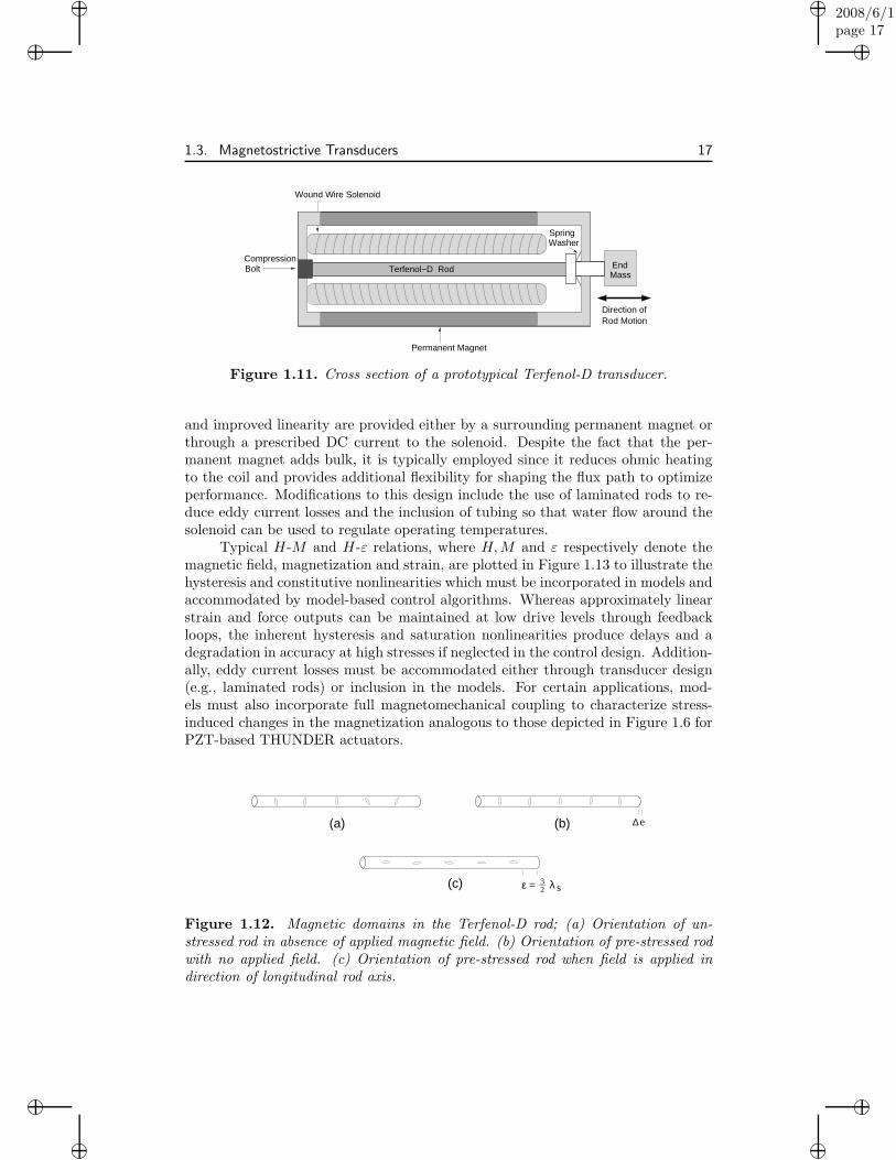
Whereas the design of Terfenol-D transducers is still evolving as the capabili-ties of the materials become better understood, a common design for numerous ap-plications is the piston transducer depicted in Figure 1.11. Strains in the Terfenol-Drod are produced when fields generated by current through the solenoid cause therotation of magnetic moments in the manner illustrated in Figure 1.12. The sensorcapabilities of the transducer are produced by the opposite effect in which stressesto the rod realign moments which produces subsequent changes in the magneti-zation. The prestress mechanism serves two roles: it increases the percentage ofmoments which are oriented perpendicular to the rod axis and it maintains the rodin a state of compression. The bias fields required to attain bidirectional strains
“book”2008/6/1page 17
i
i
i
i
i
i
i
i
1.3. Magnetostrictive Transducers 17
Direction ofRod Motion
EndMass
WasherSpring
Terfenol−D Rod
Permanent Magnet
CompressionBolt
Wound Wire Solenoid
Figure 1.11. Cross section of a prototypical Terfenol-D transducer.
and improved linearity are provided either by a surrounding permanent magnet orthrough a prescribed DC current to the solenoid. Despite the fact that the per-manent magnet adds bulk, it is typically employed since it reduces ohmic heatingto the coil and provides additional flexibility for shaping the flux path to optimizeperformance. Modifications to this design include the use of laminated rods to re-duce eddy current losses and the inclusion of tubing so that water flow around thesolenoid can be used to regulate operating temperatures.
Typical H-M and H-ε relations, where H, M and ε respectively denote themagnetic field, magnetization and strain, are plotted in Figure 1.13 to illustrate thehysteresis and constitutive nonlinearities which must be incorporated in models andaccommodated by model-based control algorithms. Whereas approximately linearstrain and force outputs can be maintained at low drive levels through feedbackloops, the inherent hysteresis and saturation nonlinearities produce delays and adegradation in accuracy at high stresses if neglected in the control design. Addition-ally, eddy current losses must be accommodated either through transducer design(e.g., laminated rods) or inclusion in the models. For certain applications, mod-els must also incorporate full magnetomechanical coupling to characterize stress-induced changes in the magnetization analogous to those depicted in Figure 1.6 forPZT-based THUNDER actuators.
∆e
23 λ sε =
(a) (b)
(c)
Figure 1.12. Magnetic domains in the Terfenol-D rod; (a) Orientation of un-stressed rod in absence of applied magnetic field. (b) Orientation of pre-stressed rodwith no applied field. (c) Orientation of pre-stressed rod when field is applied indirection of longitudinal rod axis.

“book”2008/6/1page 18
i
i
i
i
i
i
i
i
18 Chapter 1. Smart Material Applications
−0.1 −0.05 0 0.05 0.1
−0.4
−0.2
0
0.2
0.4
0.6
Field (MA/m)
Mag
netiz
atio
n (M
A/m
)
−0.1 −0.05 0 0.05 0.10
0.2
0.4
0.6
0.8
1
1.2
1.4x 10
−3
Field (MA/m)
Str
ain
(a) (b)
Figure 1.13. Hysteretic data measured in a Terfenol-D transducer as reportedin [119]: (a) field-magnetization relation, and (b) field-strain relation.
Structural, Acoustic and Industrial Applications
Examples illustrating the manner through which magnetostrictive transducerscan be employed in structural, acoustic and industrial systems are provided in Fig-ure 1.14. The configuration (a) provides a testbed for investigating the theoretical
Head
Milled Object
(d)
Cutting
(a)
Magnetostrictive
Torque
(c)
Terfenol−D Rod
Magnetostrictive
(b)
Stack
CouplingHorn
Coil
Magnetostrictive
Sensor
Transducers
Transducer
Figure 1.14. Applications utilizing magnetostrictive transducers. (a) Vibrationsensing and attenuation, (b) ultrasonic horn (after [118]), (c) torque sensing and vi-bration attenuation in a milling machine, and (d) high speed, high accuracy milling.

“book”2008/6/1page 19
i
i
i
i
i
i
i
i
1.3. Magnetostrictive Transducers 19
development of actuator/sensor models and model-based control designs as well asan initial experimental testbed for model and control validation. Figure 1.14(b)illustrates the coupling of a Terfenol-D transducer with an ultrasonic horn for ap-plications ranging from the cleaning of intricate or inaccessible machinery to thecatalysis of chemical reactions. The industrial application (c) illustrates a setting inwhich the large forces generated by the transducer can be used to attenuate vibra-tions while the inverse Wiedemann, or Matteucci, effect is employed in a noncontacttorque sensor. A second milling application is depicted in (d) where a transduceris employed for cutting out-of-round automotive parts at speeds of 3500 rpm andcutting tolerances of 1-2 µm [432,451]. A typical cutting trajectory is plotted in Fig-ure 1.15(a) to illustrate that following an initial ramp and hold to bring the cuttinghead adjacent to the ingot, the actuator must periodically drive the cutting headwhile maintaining the specified tolerances. Results from [358, 359] are plotted inFigures 1.15(c) and (d) to illustrate that robust control design alone cannot achievethe specified tolerance due to saturation nonlinearities and hysteresis-induced delays
Time
Pos
ition
0−1 0 1 2 3 4 5 6
x 104
−2
0
2
4
6
8
10
12x 10
−5
Applied Field (A/m)
Pos
ition
(m
)
(a) (b)
0 1 2 3 4 5−8
−6
−4
−2
0
2
4
6
8x 10
−6
Time
Err
or
0 1 2 3 4 5−8
−6
−4
−2
0
2
4
6
8x 10
−6
Time
Err
or
(c) (d)
Figure 1.15. (a) Trajectory to be tracked by the cutting head, and (b) hystereticrelation between H and the displacement y. (c) Error in the cutting head positionobtained with an H2 design, and (d) error obtained with an H2 design incorporatinginverse compensation.
“book”2008/6/1page 20
i
i
i
i
i
i
i
i
20 Chapter 1. Smart Material Applications
whereas robust control designs employing model-based inverse filters can maintain atracking accuracy of 1-2 µm once cutting commences — even though the transduceris operating in the hysteretic and nonlinear regime depicted in Figure1.15(b).
Additional applications utilizing Terfenol-D transducers include sonar, geo-logical tomography, bone conduction hearing aids, linear or rotational motors inaddition to torque, displacement and force sensor designs [116–118,391].
Hybrid Transducers
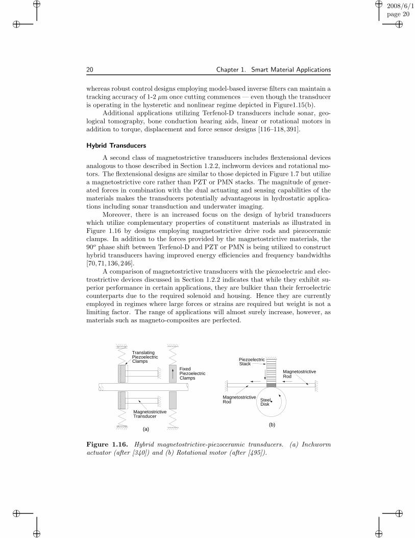
A second class of magnetostrictive transducers includes flextensional devicesanalogous to those described in Section 1.2.2, inchworm devices and rotational mo-tors. The flextensional designs are similar to those depicted in Figure 1.7 but utilizea magnetostrictive core rather than PZT or PMN stacks. The magnitude of gener-ated forces in combination with the dual actuating and sensing capabilities of thematerials makes the transducers potentially advantageous in hydrostatic applica-tions including sonar transduction and underwater imaging.
Moreover, there is an increased focus on the design of hybrid transducerswhich utilize complementary properties of constituent materials as illustrated inFigure 1.16 by designs employing magnetostrictive drive rods and piezoceramicclamps. In addition to the forces provided by the magnetostrictive materials, the90o phase shift between Terfenol-D and PZT or PMN is being utilized to constructhybrid transducers having improved energy efficiencies and frequency bandwidths[70, 71, 136,246].
A comparison of magnetostrictive transducers with the piezoelectric and elec-trostrictive devices discussed in Section 1.2.2 indicates that while they exhibit su-perior performance in certain applications, they are bulkier than their ferroelectriccounterparts due to the required solenoid and housing. Hence they are currentlyemployed in regimes where large forces or strains are required but weight is not alimiting factor. The range of applications will almost surely increase, however, asmaterials such as magneto-composites are perfected.
(a)(b)
MagnetostrictiveTransducer
Clamps
TranslatingPiezoelectric
FixedPiezoelectricClamps
SteelMagnetostrictive
Magnetostrictive
Rod Disk
PiezoelectricStack
Rod
Figure 1.16. Hybrid magnetostrictive-piezoceramic transducers. (a) Inchwormactuator (after [340]) and (b) Rotational motor (after [495]).
“book”2008/6/1page 21
i
i
i
i
i
i
i
i
1.4. Shape Memory Alloys 21
1.4 Shape Memory Alloys
1.4.1 Material Behavior
When compared with piezoelectric, electrostrictive and magnetostrictive compounds,shape memory alloys (SMA) are relative newcomers to the arena of smart mate-rials. In 1932, Swedish physicist Arne Olander observed that a deformed AuCdalloy could be returned to its original shape when heated [368], while in 1938 thetemperature-dependent nucleation and disappearance of martensite phases in brass(CuZn) was reported. Chang and Read in 1951 used x-ray analysis to establishsome of the mechanisms in the AuCd transformations and showed that systemsexploiting the shape memory effect could perform work [82]. However, the first sus-tained research on shape memory alloys is typically attributed to William Buehlerand his colleagues at the Naval Ordnance Laboratory starting in 1961 [62–64]. Thisresearch focused on nickel-titanium alloys including the equiatomic compound NiTi.Like Terfenol-D which was developed in the same facility, the generic name Nitinol(Nickel Titanium Naval Ordnance Laboratory) reflects the acronym of its origin.Subsequently developed copper-aluminum-nickel (CuAlNi), copper-zinc-aluminum(CuZnAl) and iron-manganese-silicon (FeMnSi) alloys also exhibit shape memoryeffects but Nitinol remains the most widely used shape memory alloy.
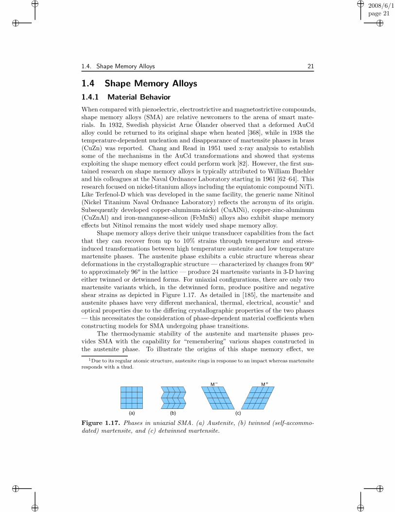
Shape memory alloys derive their unique transducer capabilities from the factthat they can recover from up to 10% strains through temperature and stress-induced transformations between high temperature austenite and low temperaturemartensite phases. The austenite phase exhibits a cubic structure whereas sheardeformations in the crystallographic structure — characterized by changes from 90o
to approximately 96o in the lattice — produce 24 martensite variants in 3-D havingeither twinned or detwinned forms. For uniaxial configurations, there are only twomartensite variants which, in the detwinned form, produce positive and negativeshear strains as depicted in Figure 1.17. As detailed in [185], the martensite andaustenite phases have very different mechanical, thermal, electrical, acoustic1 andoptical properties due to the differing crystallographic properties of the two phases— this necessitates the consideration of phase-dependent material coefficients whenconstructing models for SMA undergoing phase transitions.
The thermodynamic stability of the austenite and martensite phases pro-vides SMA with the capability for “remembering” various shapes constructed inthe austenite phase. To illustrate the origins of this shape memory effect, we
1Due to its regular atomic structure, austenite rings in response to an impact whereas martensite
responds with a thud.
−
(a) (b) (c)
MM +
Figure 1.17. Phases in uniaxial SMA. (a) Austenite, (b) twinned (self-accommo-dated) martensite, and (c) detwinned martensite.

“book”2008/6/1page 22
i
i
i
i
i
i
i
i
22 Chapter 1. Smart Material Applications
consider first the effect of temperature-induced phase transformations. In the ab-sence of an applied stress, the material transforms from austenite to twinned (self-accommodated) martensite as the material is cooled and returns to the austenitephase when reheated. The temperature at which the martensite and austenitetransformations commence are termed Ms and As, and Mf , Af denote the tem-peratures when the transformations are completed. Due to the twinning, which isenergetically favorable in the absence of a load, macroscopic strains are negligible.
Phase transformations can also be induced through applied loads. If the tem-perature of the material is above Af , the material exhibits a nearly linear stress-strain relation as the stress is increased until σMs
when a transition to the detwinnedM+ phase commences as depicted in Figure 1.18(b).2 Similarly, the material againexhibits nearly linear behavior in the martensite phase until the stress is loweredto σAs
and the reverse process begins. In this high temperature regime, full shaperecovery is observed upon unloading and the phenomenon is termed pseudoelastic orsuperelastic. For temperatures below Mf , the material retains a residual strain whenunloaded as depicted in Figure 1.18(c). When heated above Af , the deformation isrecovered and the material returns to its original shape. This low temperature be-
2It is conventional in many smart material and mechanical engineering applications, where
transducers operate in the mode of displacement control, to plot strains as the abscissae. In the
materials science literature, it is more common to plot stress on the abscissa in accordance with
mathematics and physics conventions.
Mf s As Af
Mf AsMs Af
M
εr
(b)
(d)
M
A
Pha
se
+
(c)Strain
M
Temperature
(a)Strain
Cooling
Str
ess
σ
Unloading
M
Heating
s
s
M
Austenite
Martensite
Temp
Str
ess
Loading+
Aσ
Figure 1.18. (a) Temperature-induced phase transformations between austeniteand twinned martensite in the absence of an applied load. (b) Stress-induced phasetransformation and pseudoelastic behavior for T > Af . (c) Quasiplastic behaviorand residual strain εr generated when T < Mf . (d) Recovery of the residual strainwhich produces the shape memory effect when SMA is heated above T > Af .

“book”2008/6/1page 23
i
i
i
i
i
i
i
i
1.4. Shape Memory Alloys 23
Detwinning
rε
Heating−Recovery
Cooling
T
σ
ε
Figure 1.19. Shape memory effect in a uniaxial SMA in which a residual strainεr is recovered through heating.
havior is sometimes termed quasiplastic and the recovery of stress-induced residualstrains through heating constitutes the shape memory effect (SME). The strainsassociated with martensite transformations under an applied load are illustratedin Figure 1.18(d), and generation and recovery of residual strains εr through thedetwinning and heating process are depicted in Figure 1.19. Details regarding thesephenomena are provided in Chapter 5 as a prelude to model development.
1.4.2 Applications
In a number of early applications, the shape memory properties of SMA were ex-ploited to create innovative and efficient fasteners, connectors, and clamps. Forexample, commercially available pipe couplers have been manufactured by employ-ing a Nitinol sleeve whose inner diameter is smaller than that of the adjoining pipe.The sleeve is stretched in the low temperature martensite phase and the coupledjoint is then heated to the austenite regime to recover the residual strain and pro-duce a highly effective seal. Specifically, Nitinol couplers have been used to joinhydraulic lines in F-14 fighter planes since the late 1960’s. The alloys are alsobiocompatible for most individuals which has led to their use in biomedical appli-cations including orthodontic wires which produce tooth movement as they revertfrom the high stress martensite phase to the low stress austenite phase, anchorswith Nitinol hooks to attach tendons to bone, and Nitinol guides for the insertionof catheters into blood vessels. More recently, SMA have been considered as roboticactuators, fire detection, sprinkler and gas shutoff valves which sense and respondto elevated temperatures, and highly flexible cell phone antennas which exploit thepseudoelastic properties of SMA.
To illustrate modeling and control issues associated with SMA in present inves-tigations, we discuss in detail a civil engineering application based on the pseudoe-lastic SMA behavior, an aerospace design that relies on temperature-induced phasetransformations, and thin film and microactuator designs which exploit increasedsurface area to volume ratios to achieve improved dynamic capabilities. The readeris referred to [113, 171, 177, 245, 336,413, 458] for additional examples illustrating awide range of other applications utilizing shape memory alloys.

“book”2008/6/1page 24
i
i
i
i
i
i
i
i
24 Chapter 1. Smart Material Applications
Vibration Attenuation in Civil Structures
Shape memory alloys possess a number of attributes which make them idealcandidates for vibration and displacement attenuation in civil structures, includ-ing (i) large elastic strains, (ii) significant energy dissipation capabilities due tothe hysteretic martensite transformations, (iii) strain hardening in the martensiticphase, and (iv) excellent fatigue and corrosion resistance. Among the first to exploitthese properties for civil applications were Graesser and Cozzarelli who investigatedtheir use for seismic isolation [194]. A number of subsequent investigations havefocused on vibration attenuation in bridges and buildings using Nitinol wires, rodsand composites.
These applications exploit the pseudoelastic (superelastic) behavior depictedin Figure 1.18(b), due to stress-induced phase transformations in materials con-structed so that the austenite phase occurs within the operating temperature range.Because the energy dissipated by the SMA device is proportional to the area of thehysteresis loop, the transducers are designed to maximize the hysteresis, thus neces-sitating the development of models and design packages which accommodate thisnonlinear behavior and the resulting energy losses. A significant advantage providedby SMA tendons or gaskets is the fact that they dissipate energy without stiffen-ing the structure which in turn can increase fatigue due to ensuing high frequencydynamics.
The use of SMA transducers in a multispan bridge design is illustrated inFigure 1.20. As detailed in [133], SMA restraining bars can be retrofitted to reducehinge and abutment displacements — e.g., to prevent unseating during an earth-quake — whereas Wilde et al. [510] illustrate that the addition of SMA bars tolaminated rubber bearings provides substantially improved damping capabilities aswell as displacement control due to the hardening of the bars in the high-stress,martensite phase.
Parallel investigations are focused on the development of SMA tendons to at-tenuate earthquake or wind-induced vibrations in buildings. Figure 1.21 depictsa structural testbed employed in a joint US-Japan program [7] which employstransducers comprised of Nitinol wires wrapped around cylindrical posts to reduceearthquake-induced dynamics by a factor of eight.
The use of SMA transducers to enhance passive damping capabilities also hassignificant potential for large-scale space structures — such as mirrors, antennas,
Abutment SMA Bars SMA Damper
Pier
Figure 1.20. Employment of SMA bars to reduce lateral displacements and SMAdampers for vibration attenuation on a multispan bridge.

“book”2008/6/1page 25
i
i
i
i
i
i
i
i
1.4. Shape Memory Alloys 25
SMA
Earthquake
Wind
Figure 1.21. Six story test frame used to investigate the use of SMA tendons toattenuate earthquake or wind-induced vibrations in buildings (after [7]).
and solar arrays — due to the increased emphasis on lightweight polymers and com-posites which provide minimal internal damping. This is illustrated in Figure 1.22by the depiction of an electrostrictive membrane mirror employing SMA tendonsboth for deployment and vibration attenuation.
It is anticipated that the exploitation of pseudoelastic SMA behavior for vi-bration attenuation in civil aerospace and aeronautic systems will burgeon as thetechnology matures. An important component of this technology is the combineddevelopment of hierarchical multiscale characterization frameworks ranging frommicromechanic models necessary for material design to low-order macroscopic mod-els that are sufficiently efficient for system design and real-time control implemen-tation.
SMA Designs for Improved Flight Characteristics
The high work density-to-weight ratio of shape memory alloys makes themideal candidates for a variety of aerospace applications. In the 1995 Smart WingProgram, SMA torque tubes were employed to modify aerodynamic properties of anairfoil to increase lift and rolling moments [273,274]. This illustrated the potentialof bulk SMA to improve flight characteristics within the constraint mandated bylow switching frequencies.
A
+M
MembraneMirror
Isolation System
Strain
Str
ess
SMA Vibration
Figure 1.22. SMA tendons employed to attenuate vibrations in a membrane mirrorby optimizing the pseudoelastic damping (area of hysteresis loop).

“book”2008/6/1page 26
i
i
i
i
i
i
i
i
26 Chapter 1. Smart Material Applications
(b)SMA Strips
(c)
(a)
Chevron
Takeoff
Temperature
Tip
Pos
ition
Cruise
Figure 1.23. (a) Jet engine and (b) SMA-driven chevrons employed to reduce jetnoise and decrease drag. (c) Temperature-dependent behavior of 2-D or 3-D SMAflaps as a function of flight characteristics.
Present investigations at Boeing are focused on the use of SMA flaps to reducejet noise through improved mixing while maintaining efficient flight profiles [74,311]. To illustrate the strategy and related research issues, consider the chevrondepicted in Figure 1.23(b) which is located at the outlet of a jet engine, as shownin Figure 1.23(a). The strategy is to employ SMA flaps to position the chevron inthe flow to improve mixing and decrease jet noise during takeoff and then to retractthe chevron during cruise to reduce drag. This action utilizes the shape memoryeffect in the manner depicted in Figure 1.23(c). While proof-of-concept experimentsperformed at Boeing have demonstrated a 4 dB reduction in jet noise — a 3 dBreduction is measured if one of the two engines is turned off – the optimal design andcontrol of SMA-driven chevrons requires the development of comprehensive modelsand model-based control techniques. This provides a significant challenge and is apresent research direction since the SMA flaps are necessarily 2-D or 3-D whereasthe majority of existing SMA models which are sufficiently low-order for optimaldesign and real-time model-based control algorithms are uniaxial or 1-D.
SMA Microactuators
SMA films, membranes, thin wires and microcantilevers are increasingly in-vestigated for use as microactuators in applications ranging from infrared imagingto biomedical instruments for minimally-invasive surgery. Their advantage derivesfrom a number of factors including large achievable strains, low drive voltages, highpower-to-weight ratios and improved switching frequencies. As noted in [323, 324]SMA films heat in milliseconds in response to low voltage Joule heating (∼ 5V),generate force and strokes on the order of 100 mN and 1%, and exhibit outputwork densities on the order of 10 MJ/m3. For comparison, it is noted in Table 1of [271] that thermopneumatic microactuators exhibit a work density of approxi-mately 1.2 MJ/m3 whereas that of PZT is approximately 0.12 MJ/m3 — and forthe fitness advocate, we note that the work density of muscle is approximately0.02 MJ/m3. Finally, the small thermal inertia and increased surface-to-volume ra-tios of SMA films and thin wires facilitate fast cooling and higher switching frequen-cies than their macroscopic counterparts with present designs having the potentialto achieve 100 Hz [310,426].

“book”2008/6/1page 27
i
i
i
i
i
i
i
i
1.4. Shape Memory Alloys 27
A number of investigations have focused on the design of SMA microgrip-pers which have the following advantages over conventional miniaturizations: theydo not emit any lubricants or particles, they can be integrated into existing mi-croassemblies, they exhibit clean room suitability and are biocompatible, and theypermit fine-scale resolution of gripping forces. A biomedical grasper design dis-cussed in [140] is depicted in Figure 1.24. This microinstrument is fabricated froma 0.3 mm diameter SMA tubing and is under investigation for clot removal in thebrain or retrieval of coils used to seal aneurysms that have subsequently broken freeinto the bloodstream.
A survey of issues and applications associated with SMA thin films can befound in [236]. As detailed there and [323], thin film actuator designs includemicropumps [521], microvalves [265], micromirrors, microswitches, micromechan-ical energy storage devices, and vibration dampeners in microelectronics packag-ing [223].
Biomedical applications exploiting the pseudoelastic and shape memory ef-fects of SMA are summarized in the survey articles by Duerig [140] and Duerig,Pelton and Stockel [141]. A number of these devices are being designed to oper-ate in arteries, veins and even capillaries which necessitates miniaturization. Forexample, thin film TiNi stents are being developed for small blood vessels in thebrain (on the order of 1 mm) whereas Nitinol guides used to redirect catheters orneedles presently have diameters of 1–2 mm. On a slightly larger scale, SMA servo-actuators play a fundamental role in “active endoscope” designs being developed toimprove diagnostics while reducing discomfort and risk to the patient. The resultingmicrotechnology has potential application to catheter design and remote inspectiondevices for aeronautic, aerospace, automotive and industrial processes.
Fundamental requirements for all miniaturized devices employing SMA are ac-curate characterization techniques and control designs capable of achieving specifiedtolerances. This necessitates the development of nonlinear models (often 2-D and3-D), which quantify phase transition-induced hysteresis, and model-based controltechniques that can be implemented in real-time. Whereas components of requisitemodels and control designs are presently in place, the extensions and implemen-tation issues associated with 2-D and 3-D SMA designs pose significant challengeswhich have not yet been adequately addressed.
Clot
Nitinol Grasper
Figure 1.24. Nitinol grasper designed to remove blood clots or retrieve embolizedocclusion coils from the bloodstream (after [140]).
“book”2008/6/1page 28
i
i
i
i
i
i
i
i
28 Chapter 1. Smart Material Applications
1.5 Piezoelectric, Electrostrictive and Ionic Polymers
Piezoelectric, electrostrictive and ionic polymers are similar to piezoceramic com-pounds due to the fact that they exhibit electromechanical coupling which providesthem with sensor and actuator capabilities. However, their polymer nature providesthem with unique dielectric and mechanical properties which prove advantageous ina number of smart material applications. To illustrate these capabilities, we focusindividually on semicrystalline, amorphous, and ionic polymer compounds.
1.5.1 Semicrystalline Polymers
The first piezoelectric polymer to be widely utilized and the most popular to dateis polyvinylidene fluoride (PVDF) whose piezoelectric properties were discoveredby Kawai in 1969 [261]. Other semicrystalline polymers include copolymers ofPVDF with trifluoroethylene (TrFE) and tetrafluoroethylene (TFE), odd-numberedpolamides or nylons, liquid crystal polymers, and biopolymers. Due to its prevalencein applications, we focus on PVDF and refer the reader to [209, 503] for detailsregarding the morphology and usage of other semicrystalline polymers.
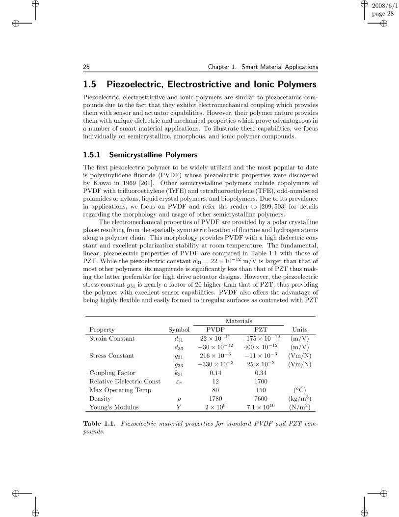
The electromechanical properties of PVDF are provided by a polar crystallinephase resulting from the spatially symmetric location of fluorine and hydrogen atomsalong a polymer chain. This morphology provides PVDF with a high dielectric con-stant and excellent polarization stability at room temperature. The fundamental,linear, piezoelectric properties of PVDF are compared in Table 1.1 with those ofPZT. While the piezoelectric constant d31 = 22× 10−12 m/V is larger than that ofmost other polymers, its magnitude is significantly less than that of PZT thus mak-ing the latter preferable for high drive actuator designs. However, the piezoelectricstress constant g31 is nearly a factor of 20 higher than that of PZT, thus providingthe polymer with excellent sensor capabilities. PVDF also offers the advantage ofbeing highly flexible and easily formed to irregular surfaces as contrasted with PZT
Materials
Property Symbol PVDF PZT Units
Strain Constant d31 22 × 10−12 −175 × 10−12 (m/V)
d33 −30 × 10−12 400 × 10−12 (m/V)
Stress Constant g31 216 × 10−3 −11 × 10−3 (Vm/N)
g33 −330 × 10−3 25 × 10−3 (Vm/N)
Coupling Factor k31 0.14 0.34
Relative Dielectric Const εr 12 1700
Max Operating Temp 80 150 (oC)
Density ρ 1780 7600 (kg/m3)
Young’s Modulus Y 2 × 10⁹ 7.1 × 10¹⁰ (N/m2)
Table 1.1. Piezoelectric material properties for standard PVDF and PZT com-pounds.

“book”2008/6/1page 29
i
i
i
i
i
i
i
i
1.5. Piezoelectric, Electrostrictive and Ionic Polymers 29
which is inflexible due to its ceramic nature. The sensor capabilities of PVDF areaugmented by the low stiffness and density which provides the compound with ahigh voltage sensitivity to stress. Moreover, the fact that the polymer exhibits ahigh dielectric breakdown means that PVDF actuators can withstand much higherdrive fields than their PZT counterparts. Whereas these high field capabilities proveadvantageous in certain transducer designs, it also means that significant hysteresisin the E-P relation, as illustrated in Figure 1.25, must be incorporated in modelsand control designs. Finally, while the polarization behavior of PVDF is stableat room temperature, its performance degrades significantly above approximately80 oC which limits its high temperature utility.
Rather than attempt to catalogue applications utilizing PVDF actuators andsensors, we summarize here only a few representative examples and refer the readerto [177, 209, 503] for more comprehensive discussion on this topic. The flexibility,light weight, low acoustic and mechanical impedance, and facility for being cutin complex patterns or bonded to irregular surfaces made PVDF films immediatecandidates for structural and structural acoustic sensing [96, 98]. There has beensignificant discussion regarding the possibility of designing distributed modal sensorsthrough the shaping and placement of PVDF films on vibrating structures [66,197,288,341,488]. While the concept is intriguing, Clark and Burke [97] illustrate thatthere are stringent practical limitations including the necessity of requiring thatboundary conditions on 2-D structures satisfy orthogonality constraints betweenthe sensor aperture and both structural modes and their curvature. An alternativefor providing distributed sensing capabilities is the differential poling of PVDF toprovide gradients or regions having differing electromechanical sensitivities. Whileagain a promising idea, technological issues remain to be resolved and the conceptis still under investigation.
−100 −50 0 50 100
−0.06
−0.04
−0.02
0
0.02
0.04
0.06
Electric Field
Pol
ariz
atio
n
Figure 1.25. PVDF data from [443] collected at 20 mHz with input fields havingmaximum values of 85 MV/m and 120 MV/m.

“book”2008/6/1page 30
i
i
i
i
i
i
i
i
30 Chapter 1. Smart Material Applications
PVDF
ElectrodesMetal
Frame
Clamps
Figure 1.26. Contactless keyboard employing PVDF after [503].
The direct piezoelectric effect has been utilized in electromechanical devicessuch as the contactless keyboard depicted in Figure 1.26. As detailed on page 322of [503], the application of pressure to metal electrodes stretches the film thusproducing a charge which initiates the desired action. The advantages provided bysuch designs are low cost and durability due to the reduction in moving parts.
Finally, the biocompatibility, conformability and impedance of PVDF andother electroactive polymers make them excellent candidates for a wide range ofbiomedical applications. This includes actuator implants to stimulate bone andtissue growth, sensors to monitor vascular stints and grafts, and artificial muscleactuators [320].
1.5.2 Amorphous Polymers
Amorphous polymers are similar to semicrystalline polymers in the general sensethat they exhibit permanent molecular dipoles which reorient in response to ap-plied fields to produce actuator effects with converse actions yielding sensor capa-bilities. As detailed in [209, 371], however, the electromechanical mechanisms forthe two classes differ quite substantially. Specifically, PVDF and the previouslymentioned polymers operate in a state of thermal equilibrium whereas amorphouspolymers exhibit piezoelectric properties in a quasi-static state due to the freezing-in or locking of dipoles below a glass transition temperature Tg. This providesamorphous polymers with higher temperature operating capabilities — 200 oC for(β-CN) APB/ODPA polyimide as compared with 80-100 oC for PVDF — but atthe expense of reduced dielectric and remanence properties. For example, d31 forpolyimides is roughly one quarter that of PVDF which has limited their use in highdrive actuator design.
Presently, polyimides are employed primarily as passive or protective compo-nents in smart material transducers. To illustrate, consider the MEMs thin filmactuator design depicted in Figure 1.27. As detailed in [147], the actuator is com-prised of a polyimide/gold/polyimide composite flap adjacent to an electroded sub-strate comprised of silicon, glass or sapphire. During the manufacturing process,differing thermal properties of the constituent materials cause the flap to curl dueto the same thermal stress mechanisms which produce the curvature in THUNDERtransducers as depicted in Figure 1.6. Actuation is achieved by applying voltageto the electroded flap and substrate causing the film to simultaneously flatten anduncurl due to attractive electrostrictive forces. When the voltage is terminated, the

“book”2008/6/1page 31
i
i
i
i
i
i
i
i
1.5. Piezoelectric, Electrostrictive and Ionic Polymers 31
(b)
PolyimideInsulating
Flexible Gold Electrode
(c)
(a)
SubstrateFluidFlow
Electrode
Polyimide
Fixed
Figure 1.27. (a) Electrostatic MEMs actuator comprised of gold and polyimidelayers adjacent to an electroded surface employed as a microfluidic valve. (b) Openaperture in the absence of voltage, and (c) closed aperture resulting from an appliedvoltage.
flap recoils to is original curved state. By varying the geometry and thickness ofthe gold and polyimide layers, one can modify the effective aperture, while achiev-ing mechanical displacements on the order of 100 µm at actuation speeds less than100 µs and frequencies greater than 5 kHz. Moreover, the actuators require littlepower with individual devices using less than 50 µW. This thin film MEMs designis presently being considered for applications which include electrical relays andswitches, integrated infrared choppers for night vision cameras, optical shutters,and microfluidic valves.
To date, the use of amorphous polymers for high performance transducerdesign lags significantly behind PVDF. However, as the material properties andcharacterization of amorphous polymers matures and high temperature operatingrequirements become increasingly stringent, their use in biomedical, aerospace, androbotic applications will likely grow.
1.5.3 Ionic Polymers
Building on research from the 1940’s [260, 275], ionic polymers were investigatedin the 1960’s for use in water desalinization and chemoelectric power generation.Developments in materials science during the 1980’s led to improvements in me-chanical strength and ionic conductivity which were capitalized on in the 1990’s byOrguro, Kawami and Takenaka [366], Sadeghipour, Salomon and Neogi [399], Segal-man et al. [414], and Shahinpoor [418–420] who established the use of ionic polymersfor actuating and sensing in a broad range of structural, robotic and biomimetricapplications as summarized in [421,522].
Ionic polymers differ from the previously described PVDF, polyimide andpolymeric elastomers in the manner through which electromechanical coupling is

“book”2008/6/1page 32
i
i
i
i
i
i
i
i
32 Chapter 1. Smart Material Applications
generated and manifested. Specifically, electromechanical coupling in ionic polymersis produced through the transport of charged and uncharged ions within the polymermatrix. To illustrate, consider the configuration depicted in Figure 1.28, whichconsists of a teflon polymer backbone sulfanated with negatively charged side groupsin a hydrated membrane with conductive surfaces. Application of an electric fieldacross the membrane produces ionic migration toward the negative surface whichcombines with the redistribution of solvent to produce bending in the structure– this provides the membrane with actuator capabilities. Conversely, mechanicaldeformations produce a redistribution of charges and solvent which produces anelectric field – this gives the polymer sensor capabilities.
The unique electromechanical properties of ionic polymers provide them withthe following properties:
• Strain outputs greater than 1% (PZT: 0.1-0.3%)
• Operating voltages on the order of 1-10 V (PZT: 1-2000 V)
• Chemoelectric coupling properties
• Controllable charge and solvent transport properties.
The fact that electromechanical coupling is directly related to charge transportprovides the materials with the potential for chemical sensing [302]. This latter ca-pability is illustrated in Figure 1.29 where an ionic polymer coated with a chemical-specific permeable membrane is used to separate two reservoirs. Introduction of thechemical in Reservoir I will cause a concentration gradient which in turn producesdiffusion from Reservoir I to Reservoir II. The accompanying charge flow generatesa stress which can be measured to monitor the presence of the chemical.
As detailed in [361,421,469], original ionic polymers required hydration whichseverely restricted their use in most aerospace and aeronautic applications. How-ever, recent investigations have illustrated that significant strain and stress outputscan be achieved by constructs in which active ionic polymers are encapsulated inpolyimides to provide space durability and the possibility for operation in nonhy-drated environments. This provides the potential for substantially expanding theutility of ionic polymers for a broad range of aerospace and aeronautic applications.
−
−−
−
−
+
++
+
+
+
+
+
− −
−−
−
−
+
Electrodes
BackbonePolymerTeflon
Cathode
Anode
HydratedMobile Cation
ImmobileAnion
WaterMolecule
Figure 1.28. Electromechanical transduction in ionic polymers in response to anapplied field.
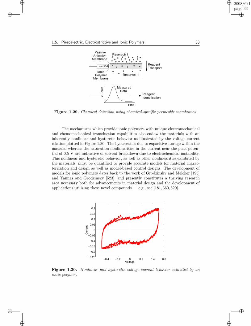
“book”2008/6/1page 33
i
i
i
i
i
i
i
i
1.5. Piezoelectric, Electrostrictive and Ionic Polymers 33
TimeF
orce
Load Cell
PassiveSelective
Membrane
ReagentIdentification
IonicPolymer
DataMeasured
TransportReagent
MembraneReservoir II
Reservoir I
Figure 1.29. Chemical detection using chemical-specific permeable membranes.
The mechanisms which provide ionic polymers with unique electromechanicaland chemomechanical transduction capabilities also endow the materials with aninherently nonlinear and hysteretic behavior as illustrated by the voltage-currentrelation plotted in Figure 1.30. The hysteresis is due to capacitive storage within thematerial whereas the saturation nonlinearities in the current near the peak poten-tial of 0.5 V are indicative of solvent breakdown due to electrochemical instability.This nonlinear and hysteretic behavior, as well as other nonlinearities exhibited bythe materials, must be quantified to provide accurate models for material charac-terization and design as well as model-based control designs. The development ofmodels for ionic polymers dates back to the work of Grodzinsky and Melcher [195]and Yannas and Grodzinsky [523], and presently constitutes a thriving researcharea necessary both for advancements in material design and the development ofapplications utilizing these novel compounds — e.g., see [181,360,520].
−0.4 −0.2 0 0.2 0.4 0.6−0.25
−0.2
−0.15
−0.1
−0.05
0
0.05
0.1
0.15
0.2
Voltage
Cur
rent
Figure 1.30. Nonlinear and hysteretic voltage-current behavior exhibited by anionic polymer.
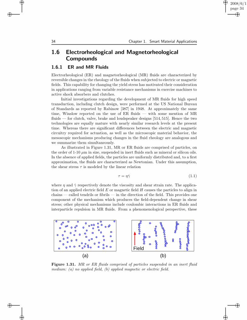
“book”2008/6/1page 34
i
i
i
i
i
i
i
i
34 Chapter 1. Smart Material Applications
1.6 Electrorheological and MagnetorheologicalCompounds
1.6.1 ER and MR Fluids
Electrorheological (ER) and magnetorheological (MR) fluids are characterized byreversible changes in the rheology of the fluids when subjected to electric or magneticfields. This capability for changing the yield stress has motivated their considerationin applications ranging from variable resistance mechanisms in exercise machines toactive shock absorbers and clutches.
Initial investigations regarding the development of MR fluids for high speedtransduction, including clutch design, were performed at the US National Bureauof Standards as reported by Rabinow [387] in 1948. At approximately the sametime, Winslow reported on the use of ER fluids — with some mention of MRfluids — for clutch, valve, brake and loudspeaker designs [514,515]. Hence the twotechnologies are equally mature with nearly similar research levels at the presenttime. Whereas there are significant differences between the electric and magneticcircuitry required for actuation, as well as the microscopic material behavior, themesoscopic mechanisms producing changes in the fluid rheology are analogous andwe summarize them simultaneously.
As illustrated in Figure 1.31, MR or ER fluids are comprised of particles, onthe order of 1-10 µm in size, suspended in inert fluids such as mineral or silicon oils.In the absence of applied fields, the particles are uniformly distributed and, to a firstapproximation, the fluids are characterized as Newtonian. Under this assumption,the shear stress τ is modeled by the linear relation
τ = ηγ (1.1)
where η and γ respectively denote the viscosity and shear strain rate. The applica-tion of an applied electric field E or magnetic field H causes the particles to align inchains — called tendrils or fibrils — in the direction of the field. This provides onecomponent of the mechanism which produces the field-dependent change in shearstress; other physical mechanisms include coulombic interactions in ER fluids andinterparticle repulsion in MR fluids. From a phenomenological perspective, these
(a) (b)
Field
Figure 1.31. MR or ER fluids comprised of particles suspended in an inert fluidmedium: (a) no applied field, (b) applied magnetic or electric field.

“book”2008/6/1page 35
i
i
i
i
i
i
i
i
1.6. Electrorheological and Magnetorheological Compounds 35
field-dependent mechanisms produce several facets of non-Newtonian behavior asillustrated for ER fluids in Figure 1.32. In the absence of motion, the fluids exhibita field-dependent static yield stress τs(E) which decreases to τy(E) once the fluid isin motion. For moderate shear strain rates, the fluids exhibit approximately affinebehavior
τ = ηγ + τy(E) (1.2)
where τy(E) incorporates the measured functional dependence of τy on the field.Similar phenomenological behavior is observed for MR fluids.
Due to its simplicity, the Bingham model (1.2) has been employed for charac-terization and design in a number of ER and MR applications. However, it ignoresthe dependence of η on the field and strain rate, the mechanisms producing thefield-dependence in τs and τy, the dynamics of the fluids, temperature-dependencies,and particle interactions, thus motivating the investigation of more sophisticatedER [48, 56, 69, 258, 375] and MR [308, 346, 428, 429,456] fluid models. The incorpo-ration of additional physical mechanisms, the construction of reduced-order modelsfeasible for real-time implementation, and the development of model-based con-trol designs which accommodate the inherently nonlinear fluid dynamics are openresearch topics necessary for the continued exploitation of MR and ER fluids.
It is a tribute to Rabinow and Winslow that a number of the MR and ERapplications under present investigation were either motivated by or described intheir pioneering work [387, 515]. These include vibration isolation devices suchas shock absorbers, seat dampers, or engine mounts, magnetically or electricallytriggered clutches, and automotive valves. As detailed in [78,144,177,207,254,317,458], additional applications include variable resistance exercise bikes and vibrationattenuation devices for civil structures which provide semi-active damping of windor earthquake-induced vibrations using minimal power — compare with the SMAdevices discussed in Section 1.3 and depicted in Figure 1.21. Finally, the reader isdirected to [68,525] for discussion regarding the development of hydraulic actuatorswhich exploit MR valves employed in combination with piezoelectric or Terfenol-Dpumps. These hybrid devices provide durability, controllable damping, high outputforces, and the facility for miniaturization; hence they exhibit great potential for anumber of aeronautic, aerospace and industrial applications.
To illustrate the use of MR fluids for clutch construction, consider the twoprototypical designs depicted in Figure 1.33. The concentric cylinder facilitates
τs(E)
γ
τ
Newtonian Fluid
ER Fluid
ShearStress
τy(E)
Shear Rate
Figure 1.32. Dependence of shear stress τ on shear strain rate γ for ER fluids.
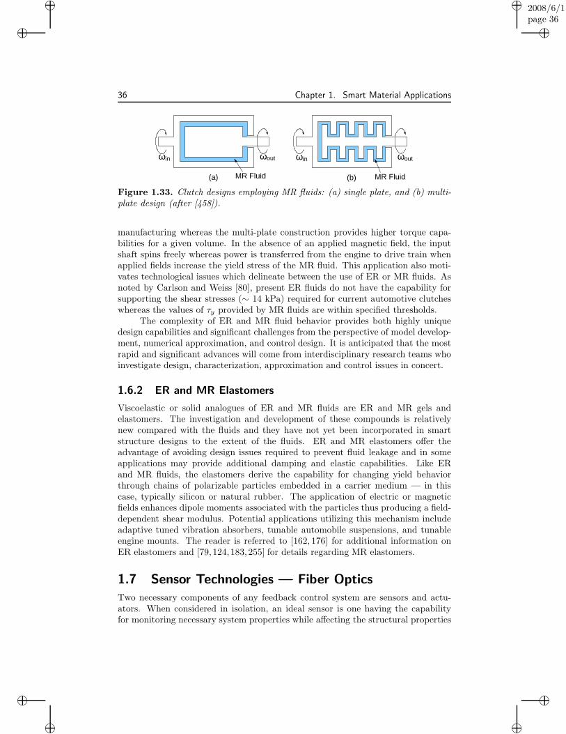
“book”2008/6/1page 36
i
i
i
i
i
i
i
i
36 Chapter 1. Smart Material Applications
in ωoutω
MR Fluid(a)
outωωin
MR Fluid(b)
Figure 1.33. Clutch designs employing MR fluids: (a) single plate, and (b) multi-plate design (after [458]).
manufacturing whereas the multi-plate construction provides higher torque capa-bilities for a given volume. In the absence of an applied magnetic field, the inputshaft spins freely whereas power is transferred from the engine to drive train whenapplied fields increase the yield stress of the MR fluid. This application also moti-vates technological issues which delineate between the use of ER or MR fluids. Asnoted by Carlson and Weiss [80], present ER fluids do not have the capability forsupporting the shear stresses (∼ 14 kPa) required for current automotive clutcheswhereas the values of τy provided by MR fluids are within specified thresholds.
The complexity of ER and MR fluid behavior provides both highly uniquedesign capabilities and significant challenges from the perspective of model develop-ment, numerical approximation, and control design. It is anticipated that the mostrapid and significant advances will come from interdisciplinary research teams whoinvestigate design, characterization, approximation and control issues in concert.
1.6.2 ER and MR Elastomers
Viscoelastic or solid analogues of ER and MR fluids are ER and MR gels andelastomers. The investigation and development of these compounds is relativelynew compared with the fluids and they have not yet been incorporated in smartstructure designs to the extent of the fluids. ER and MR elastomers offer theadvantage of avoiding design issues required to prevent fluid leakage and in someapplications may provide additional damping and elastic capabilities. Like ERand MR fluids, the elastomers derive the capability for changing yield behaviorthrough chains of polarizable particles embedded in a carrier medium — in thiscase, typically silicon or natural rubber. The application of electric or magneticfields enhances dipole moments associated with the particles thus producing a field-dependent shear modulus. Potential applications utilizing this mechanism includeadaptive tuned vibration absorbers, tunable automobile suspensions, and tunableengine mounts. The reader is referred to [162, 176] for additional information onER elastomers and [79, 124,183,255] for details regarding MR elastomers.
1.7 Sensor Technologies — Fiber Optics
Two necessary components of any feedback control system are sensors and actu-ators. When considered in isolation, an ideal sensor is one having the capabilityfor monitoring necessary system properties while affecting the structural properties

“book”2008/6/1page 37
i
i
i
i
i
i
i
i
1.7. Sensor Technologies — Fiber Optics 37
in a manner which enhances performance — e.g., improved load-carrying capacity.Hence sensors should be lightweight, flexible and capable of achieving the frequencybandwidth dictated by the application. Furthermore, they should be sufficiently ro-bust so that the lifetime of the control system is not dictated by that of the sensor.For some control designs, it may also be advantageous for sensors and actuatorsto be collocated which motivates consideration of transducer materials capable ofboth functions.
Of the previously discussed transducer materials, piezoelectric, electrostrictiveand magnetostrictive materials have been widely investigated for use as both sensorsand actuators with ionic polymers and shape memory alloys more recently joiningthe list. All offer unique features which make them candidates for the design of self-sensing actuators [11,135] or sensoriactuators [103] tailored to certain applications.
Present smart material control systems also employ a number of other sen-sor constructs including accelerometers, laser vibrometers for noncontact velocitymeasurement, proximity sensors for displacement measurement, strain gauges andfiber optics [113, 177]. While all of these choices offer advantages in various appli-cations, we summarize here the properties of fiber optic sensors due to their uniquecapability for providing high accuracy, quasi-distributed strain measurements.
1.7.1 Fiber Optic Principles
Optical fibers operate by the principle of total internal reflection which occurs whenlight encounters an interface with a material having a lower refractive index. Toillustrate, consider two materials having refractive indices n1 and n2 where n1 > n2.Snell’s law, or the law of refraction, states that if a ray has angle of incidence θ1 inthe first material, then the angle of refraction θ2 in the second material is quantifiedby the relation
sin θ2
sin θ1
=n1
n2
.
For the considered case n2 < n1, it thus follows that θ2 > θ1 as depicted in Fig-ure 1.34. The critical angle of incidence θc is defined as that which yields θ2 = π
2
so that n1 sin θc = n2 or
θc = arcsin(n2/n1).
Finally, total internal reflection occurs for θ1 > θc. In this latter regime, the raysalso satisfy the law of reflection which states that
θi = θr
where θi and θr denote the incidence angle and angle of reflection.Optical fibers are constructed from a high-index core surrounded by a cladding
material having a slightly lower refractive index as shown in Figure 1.34(b). Boththe core and cladding are typically comprised of glass (SiO2) mixed with dopants tocontrol the refractive indices. By choosing dopants so that θi > θc for the geometryand strains under consideration, optical fibers thus act as wave or light guides inthe manner depicted in Figure 1.34(c).

“book”2008/6/1page 38
i
i
i
i
i
i
i
i
38 Chapter 1. Smart Material Applications
1n
n1
(c)
(b)
rθiθ
cθ1
Core
(a)
θCladding
2θn2
n2
Figure 1.34. (a) Refraction and reflection of light at the interface between mate-rials with refractive indices n1 and n2, n1 > n2. (b) Single-mode optical fiber com-prised of a high-index silicon core surrounded by a silicon cladding with a slightlylower refractive index. (c) Travel of light rays within an optical fiber.
Single mode fibers have core diameters on the order of 5 µm whereas thediameters of multimode fibers range from 100 µm to 200 µm. From the perspectiveof structural design, optical fibers can withstand strains up to 8% which is onthe order of those generated by shape memory alloys. Their Young’s modulus(6.9 × 10¹⁰ N/m2) is close to that of aluminum (7.3 × 10¹⁰ N/m2) and PZT (7.1 ×
1010 N/m2) which facilitates impedance matching with these materials. Finally,it has been demonstrated that with the proper selection of adhesives and coatings(e.g., polyimides), optical fibers can operate in excess of 1 million cycles and, ingeneral, have a longer operating life than conventional strain gauges [458].
1.7.2 Fiber Optic Sensor Designs
There exist a number of sensor designs employing optical fibers, each proving ad-vantageous in certain applications. We summarize three designs: Mach-Zehnder in-terferometers, Fabry-Perot sensors, and Bragg grating sensors, and refer the readerto [112,113,262,483] for details regarding additional sensor designs utilizing opticalfibers. Further discussion detailing the use of fiber optic sensors for smart systemscan be found in [100,490].
Mach-Zehnder Interferometers
This class of fiber optic sensors exploits interference produced in light signalsdue to strains in the underlying structure. As depicted in Figure 1.35, a single

“book”2008/6/1page 39
i
i
i
i
i
i
i
i
1.7. Sensor Technologies — Fiber Optics 39
InputLight
Sensing Arm
Reference Arm
Sensors
OutputLight
Figure 1.35. Mach-Zehnder interferometer array which measures the interferencein a beam of light split into a reference signal which is isolated from strains and asensing signal subjected to strains.
input beam is split to provide equivalent signals in two single mode fibers. Thefirst fiber, which acts as a reference arm, is isolated from strains whereas the second(termed a sensing arm) undergoes deflections produced in the underlying structure.The differing path length in the strained fiber produces a phase shift which, whencompared with the reference signal, can be used to deduce the strain amplitude.
Mach-Zehnder interferometers offer the advantage of high sensitivity and canbe used to measure strains on the order of 10−8. The requirement of a referencearm, however, increases the complexity and size of the sensors and limits the degreeto which they can be localized or used to measure strains at a point.
Fabry-Perot Strain Sensors
Fabry-Perot sensors exploit the interference between reflected waves in thedevice to provide localized or pointwise strain measurements. The fiber optic com-ponents of the sensor consist of a single-mode fiber separated from a multimode fiberby an air gap on the order of 4 mm as depicted in Figure 1.36. When an incomingwave in the single-mode fiber encounters the glass-air interface at the beginning ofthe gap, part is reflected to provide a reference signal r1 while a sensing componentr2 continues through the gap where it is reflected at the air-glass interface withthe multimode fiber. Deformations in the underlying structure change the widthof the gap thus altering the interference between the signals r1 and r2. This inturn produces a phase change which is measured by the device. In this manner,Fabry-Perot sensors provide the capability for obtaining highly accurate, localizedstrain measurements.
r1r2
s
Hollow−Core Fiber
Single−ModeFiber
MultimodeFiber
Figure 1.36. Fabry-Perot strain sensor exploiting interference between reflectedsignals r1 and r2.

“book”2008/6/1page 40
i
i
i
i
i
i
i
i
40 Chapter 1. Smart Material Applications
An example illustrating the sensitivity of Fabry-Perot sensors is provided byMurphy et al. [354] in the context of measuring strains produced in an F-15 airframeduring fatigue tests. These results demonstrate that Fabry-Perot sensors are capableof detecting strains down to 0.01 µstrain (0.01 µm/m) while exhibiting negligiblehysteresis. Hence this technology offers strong potential for sensor design in smartmaterial systems.
Bragg Grating Sensors
One of the most promising sensor designs exploiting optical fibers is basedon the use of Bragg gratings to systematically perturb the refraction index of thefiber core in the manner depicted in Figure 1.37. The grating, which is formed byexposing the fiber to an intense optical interference pattern, acts as a step-bandfilter in the sense that it reflects certain wavelengths while allowing others to pass.As detailed in [215], the strongest interactions or reflections occur at the Braggwavelength
λB = 2neΛ
where Λ is the period for the grating and ne denotes the modal index.The sensor capabilities for the device derive from the fact that any environ-
mental changes that alter the Bragg spacing or modal index will also change λB ,a quantity that can be measured with high accuracy. For example, both axial andtransverse strains will compress or dilate the grating to produce shifts δλB in theBragg wavelength. As reported in [347], strain responses measured in this mannerare highly accurate, linear, and exhibit no hysteresis at temperatures as high as370 oC.
λBλB= 2Λ
Grating
λ
λ
IInput Signal
tTransmitted Signal
Λ
λ iλB
λ
t
IStrain−Induced
i I
λ
B
ReflectedSignal
Spectrum Shift
FiberCore
Figure 1.37. A fiber Bragg grating (FBG) generating a reflected wave havingthe Bragg wavelength λB = 2neΛ. Changes in the modal index ne or grating pe-riod Λ due to strains, temperature deviations, or changes in polarization producecorresponding shifts in λB which provides the device with highly sensitive sensorcapabilities.
“book”2008/6/1page 41
i
i
i
i
i
i
i
i
1.7. Sensor Technologies — Fiber Optics 41
The elasto-optic properties of the grated fibers also provide the capability fordetecting pressure changes and measuring acoustic fields. Like strain measurements,large pressure changes can be monitored with simple readout devices. As notedin [215], however, the stiffness of the glass fibers necessitates the use of geometricor complex readout systems when detecting sound fields due to the low amplitudeof generated transverse strains.
Fiber Bragg grating (FBG) sensors can also be used to measure temperatureas well as electric and magnetic fields. The temperature sensitivity derives from thethermo-optic properties of the device and care must be taken to insulate againstthis effect if measuring other quantities in variable temperature environments. Theability to measure magnetic or electric fields is induced by coating the fibers withmagnetostrictive or piezoelectric jackets. As with the acoustic sensors, the inducedstrains are small so fine-scale readout techniques are required to resolve the mea-surands.
The advantage of FBG sensors are augmented by the fact that the shifts inwavelength used to measure strains, temperature changes, and electric, magneticand acoustic fields are independent of intensity and do not change as the light passesthrough adjacent fibers or connectors. This enhances the robustness of the devices.Finally, FBG technology is being heavily investigated for numerous other applica-tions ranging from optical storage to telecommunications [215] which will continueto produce technological advances that benefit sensing for smart material systems.