2008-prefabricated vertical drain - the squeeze is on-wick drain(pvd)
TRANSCRIPT
Slim. Sleek. Flexible. Durable. Reliable. Prefabricated Vertical (PV) drains may be light in weight but they deliver a heavy blow to slow-draining soils. PV drains,
also known as wick drains in the U.S. and band drains in other parts of the world, can provide a low-cost, practical, and effective means of expediting consolidation settlement in fine-grained soils.
Pre-loading, or surcharging, is a time-tested, effective method for increasing the strength of soft soils by apply-ing a temporary load to the ground that exerts stress simi-lar, or slightly greater, than the anticipated stress from the proposed structure. Pore water pressure and settlement are monitored to ensure that the surcharge fill can be safely placed and that the desired percentage of settlement has occurred before the surcharge is removed. With slow-drain-ing soils, the pre-loading process can take years or decades. Wick drains can reduce the pre-loading time from several years to a few months; they are intended to expedite settle-ment rather than reduce it.
The Vertical Drain ConceptThe duration of the pre-load period is controlled by soil
consolidation characteristics, pore water travel distance, and surcharge height. Consolidation characteristics of soil particles are challenging to enhance and there are practical and safety limitations for surcharge height. Without vertical drains, the pore water travel distance is taken to be equal to either the thickness or one-half of the thickness of the strata undergoing consolidation. With properly-designed vertical drains, pore water will flow laterally to the closest drain rather than vertically to the underlying or overlying drainage layer and the drainage distance is significantly reduced. For example, if drains spaced 5 feet apart on a triangular grid pattern are installed through a 100-foot-thick layer that has no bottom drainage, travel distance is reduced by a factor of approximately 30.
In the 1920s, a technique for installing sand drains was patented in the U.S. Shortly thereafter, the first wick drains, consisting of layers of cardboard, were developed in Sweden. Cardboard wick drains, and subsequently paper-wrapped plastic drains, were installed outside of the U.S. through the 1970s. Introduced in the U.S. in the mid- to late-1970s,
entirely plastic PV drains had become durable, reliable, and inexpensive, and could be installed very quickly as com-pared to sand drains. By the mid-1980s, PV drains had sig-nificantly replaced sand drains, which have been rendered almost obsolete in the U.S.
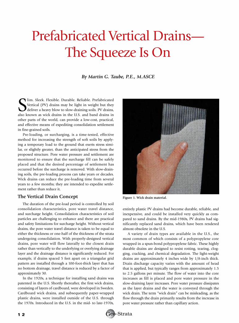
A variety of drain types are available in the U.S., the most common of which consists of a polypropylene core wrapped in a spun-bond polypropylene fabric. These highly durable drains are designed to resist rotting, tearing, clog-ging, cracking, and chemical degradation. The light-weight drains are approximately 4 inches wide by 1/8-inch thick. Drain discharge capacity varies with the amount of head that is applied, but typically ranges from approximately 1.5 to 2.5 gallons per minute. The flow of water into the core increases as fill is placed and pore water pressure in the slow-draining layer increases. Pore water pressure dissipates as the layer drains and the water is conveyed through the wick drain. The term “wick drain” can be misleading, as the flow through the drain primarily results from the increase in pore water pressure rather than capillary action.
1 � eo-StrataG
Prefabricated Vertical Drains— The Squeeze Is On
By Martin G. Taube, P.E., M.ASCE
Figure 1. Wick drain material.
Wick Drain Applications
Today, surcharges with wick drains are widely used for warehouses, storage tanks, residential and retail structures, roadways, airport runways, industrial facilities, port and marine construction, and MSE walls. When wick drains are used to expedite consolidation for soft ground underlying fills and earthen features such as berms, dikes, levees, and embankments, the goal is to allow for the feature to be con-structed and put into service as quickly as possible. In par-ticular, vertical drains serve to accelerate construction and reduce both the time and magnitude of post-construction settlement. They may also allow for construction of higher fills and steeper slopes because of the rapid strength increase in the treated soils.
In addition to expediting settlement for fills and pre-loads, wick drains have been used to reduce potential down drag on piles, to increase storage capacity for future landfills and waste containment sites, and for collection and extrac-tion of floating product and contaminated groundwater.
Wick drains are commonly used for large, above-ground storage tanks, ranging in diameter from 100 feet to 350 feet, with product heights of up to 40 feet. Wick drains can be installed prior to a conventional soil sur-charge, or, in some cases, the soil surcharge is foregone and the wick drains are installed after the ring wall but prior to tank construction. When installed without the soil surcharge, the pre-loading takes place as the tank hydro-test is performed. Once the desired amount of con-solidation is achieved, the tank can be re-leveled, if neces-sary, and put in service.
Soils suitable for wick drains include clays, silts, organic layers, peat, clayey and silty sands, dredge spoils, and wastes such as mine tailings and industrial sludges. The scale of wick drain applications can range from a few hundred to
several million linear feet. Recently, near Atlantic City, NJ, approximately 65,000 wick drains were installed to treat soft, compressible organic layers to depths of 40 feet for the construction of 134 townhouse units and surrounding grounds, resulting in approximately 3—4 feet of settlement.
The effects of a soil surcharge can be replicated or enhanced by applying a vacuum to a vertical drain to draw the water from slow-draining layers. This technique, known as Menard VacuumTM Consolidation, relies on the estab-lishment of a vacuum created under an airtight sealed liner system. The vacuum creates an isotropic state of stress in the soils which replicates the effect of a 12-ft.-high soil sur-charge. Recently, in Camau, Vietnam, the Menard VacuumTM
Consolidation system was used to improve 1.7 million square feet of soft clay for the construction of a power plant. The soft clay was up to 55 feet thick and the induced settle-ment was between 6.5 and 10 feet.
InstallationFollowing the initial set up and feeding of the wick
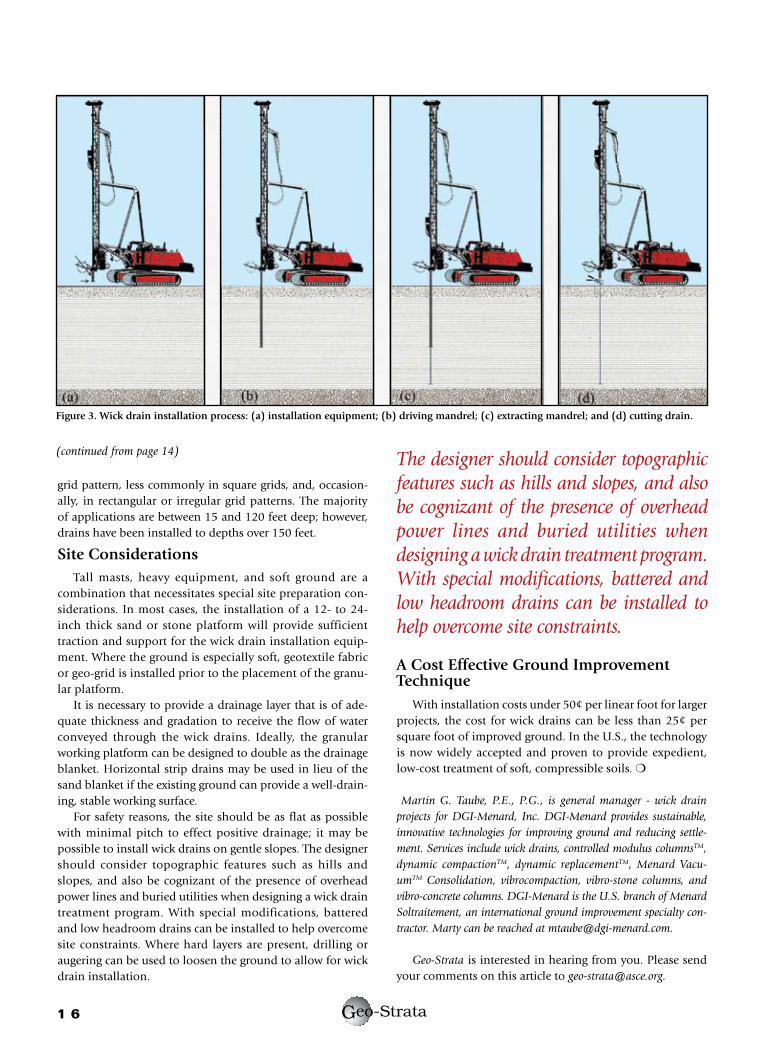
drain material, the drains are installed by pushing a hol-low, steel mandrel, typically rectangular or rhombic in section, into the ground. The mandrel houses the wick material and protects it from damage as the mandrel is inserted into the ground to the termination depth. At the base of the mandrel, the wick material is looped through an anchor which holds the drain securely in place as the mandrel is extracted. Once the mandrel has been extracted from the ground, the wick drain is cut and the next drain is installed. In some sites, production rates greater than one drain per minute can be achieved.
Wick drain installation units are typically powered and supported by large crawler excavators or by cranes, depend-ing on the depth of the drain and weight of the installation unit. Pull down is typically accomplished by heavy chain, cable, or gear systems. Depending on the subsurface condi-tions, the mandrel may be vibrated or statically pushed into the ground. The mandrel cross-sectional area is typically 10—12 square inches.
Wick drain center-to-center spacing is usually in the range of 3—8 feet. The drains are typically laid out in a triangular
1 � eo-StrataG
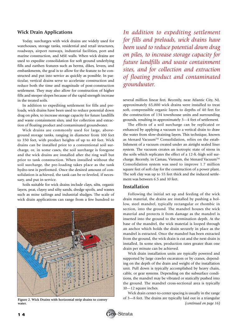
Figure 2. Wick Drains with horizontal strip drains to convey water.
In addition to expediting settlement for fills and preloads, wick drains have been used to reduce potential down drag on piles, to increase storage capacity for future landfills and waste containment sites, and for collection and extraction of floating product and contaminated groundwater.
(continued on page 16)
1 � eo-StrataG
grid pattern, less commonly in square grids, and, occasion-ally, in rectangular or irregular grid patterns. The majority of applications are between 15 and 120 feet deep; however, drains have been installed to depths over 150 feet.
site ConsiderationsTall masts, heavy equipment, and soft ground are a
combination that necessitates special site preparation con-siderations. In most cases, the installation of a 12- to 24-inch thick sand or stone platform will provide sufficient traction and support for the wick drain installation equip-ment. Where the ground is especially soft, geotextile fabric or geo-grid is installed prior to the placement of the granu-lar platform.
It is necessary to provide a drainage layer that is of ade-quate thickness and gradation to receive the flow of water conveyed through the wick drains. Ideally, the granular working platform can be designed to double as the drainage blanket. Horizontal strip drains may be used in lieu of the sand blanket if the existing ground can provide a well-drain-ing, stable working surface.
For safety reasons, the site should be as flat as possible with minimal pitch to effect positive drainage; it may be possible to install wick drains on gentle slopes. The designer should consider topographic features such as hills and slopes, and also be cognizant of the presence of overhead power lines and buried utilities when designing a wick drain treatment program. With special modifications, battered and low headroom drains can be installed to help overcome site constraints. Where hard layers are present, drilling or augering can be used to loosen the ground to allow for wick drain installation.
A Cost effective Ground Improvement Technique
With installation costs under 50¢ per linear foot for larger projects, the cost for wick drains can be less than 25¢ per square foot of improved ground. In the U.S., the technology is now widely accepted and proven to provide expedient, low-cost treatment of soft, compressible soils. m
Martin G. Taube, P.E., P.G., is general manager - wick drain projects for DGI-Menard, Inc. DGI-Menard provides sustainable, innovative technologies for improving ground and reducing settle-ment. Services include wick drains, controlled modulus columnsTM, dynamic compactionTM, dynamic replacementTM, Menard Vacu-umTM Consolidation, vibrocompaction, vibro-stone columns, and vibro-concrete columns. DGI-Menard is the U.S. branch of Menard Soltraitement, an international ground improvement specialty con-tractor. Marty can be reached at [email protected].
Geo-Strata is interested in hearing from you. Please send your comments on this article to [email protected].
Figure 3. Wick drain installation process: (a) installation equipment; (b) driving mandrel; (c) extracting mandrel; and (d) cutting drain.
The designer should consider topographic features such as hills and slopes, and also be cognizant of the presence of overhead power lines and buried utilities when designing a wick drain treatment program. With special modifications, battered and low headroom drains can be installed to help overcome site constraints.
(continued from page 14)