©2006 opensystems publishing. not for...
TRANSCRIPT
©2006 OpenSystems Publishing. Not for distribution.
For Single Print Only

RSC# � @ www.industr ial-embedded.com/rsc©2006 OpenSystems Publishing. Not for distribution.
For Single Print Only
RSC# � @ www.industr ial-embedded.com/rsc©2006 OpenSystems Publishing. Not for distribution.
For Single Print Only
Published by:©2006 Industrial Embedded SystemsOpenSystems
Publishing™
All registered brands and trademarks within Industrial Embedded Systems are property of their respective owners.
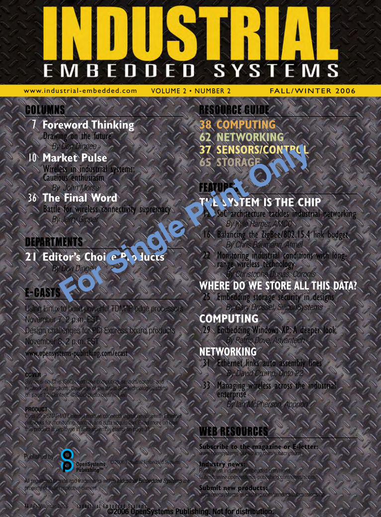
COLUMNS 7ForewordThinking Drawingonthefuture
By Don Dingee
10MarketPulse Wirelessinindustrialsystems:
CautiousenthusiasmBy John Morse
36TheFinalWord Battleforwirelessconnectivitysupremacy
By Jerry Gipper
DEPARTMENTS21Editor’sChoiceProducts
By Don Dingee
E-CASTSUsing Linux to build powerful TDM/IP edge processorsNovember 7, 2 p.m. ESTDesign challenges for PCI Express board productsNovember 8, 2 p.m. ESTwww.opensystems-publishing.com/ecast
COVERSystems-on-Chip (SoCs) combine computing, sensors/control, and networking functions. Coverage of the latest SoC technologies starts on page 12. Content: ©iStockphoto.com/Ye Liew
PRODUCTOpto 22’s SNAP I/O Ethernet module connects digital devices with Ethernet networks for monitoring, control, and data acquisition. Read more on how this product is deployed in auto assembly plants on page 31.
RESOURCE GUIDE38COMPUTING62NETWORKING37SENSORS/CONTROL65STORAGE
FEATURESTHESYSTEMISTHECHIP12SoCarchitecturetacklesindustrialnetworking
By Kyle Harper, AMCC16BalancingtheZigBee/802.15.4linkbudget
By Chris Baumann, Atmel22 Monitoringindustrialconditionswithlong-
rangewirelesstechnologyBy Christophe Dugas, Coronis
WHEREDOWESTOREALLTHISDATA?25 Embeddingstoragesecurityindesigns
By Gary Drossel, SiliconSystems
COMPUTING29 EmbeddingWindowsXP:Adeeperlook
By Patric Dove, Advantech
NETWORKING31 Ethernetlinksautoassemblylines
By David Crump, Opto 22
33 Managingwirelessacrosstheindustrialenterprise
By Ian McPherson, Apprion
WEB RESOURCESSubscribetothemagazineorE-letter:www.opensystems-publishing.com/subscriptions
Industrynews:Read: www.industrial-embedded.com/news Submit: www.opensystems-publishing.com/news/submit
Submitnewproducts:www.opensystems-publishing.com/vendors/submissions/np
www.industr ia l -embedded.com Volume2• Number2 fall / WiNter2006
� / Fall/Winter 2006 I n d u s t r i a l E m b e d d e d S y s t e m s©2006 OpenSystems Publishing. Not for distribution.
For Single Print Only

SMA Computers9550 Warner Ave. #250Fountain Valley, CA 92708Phone +1 [email protected]
ENDURO OUTDOORWireless Communication for Mobile Applications
www.SMAcomputers.com
■ Waterproof housing (IP 67) ■ Shock and vibration resistant (EN 50155)■ -40°C to +50 °C, fanless
The Enduro Outdoor is a rugged industrial communicationPC. Install it anywhere on the vehicle, regardless of wiringor protection against environmental conditions, and whereinstallation and maintenance are fast and easy. WhetherGSM, GPS, GPRS, or UMTS – the Enduro Outdoor han-dles all modern radio communication standards.
SMA Technologie AGHannoversche Strasse 1–534266 Niestetal, GermanyPhone +49 561 9522 [email protected]
WirelessWireless
WIR
ELES
S-01
:AU
-8x1
0_7/
8--3
906
Anzeige-Wireless-ENDURO_OUTDOOR2006_203,2x276,2.qxd 29.09.2006 03:01 Seite 1
RSC# � @ www.industr ial-embedded.com/rsc©2006 OpenSystems Publishing. Not for distribution.
For Single Print Only
A n O p e n S y S t e m S p u b l i c A t i O n
ISSN: Print 1932-2488 Online 1932-2496
Industrial Embedded Systems is published semi-annually by OpenSystems Publishing LLC., 30233 Jefferson Ave., St. Clair Shores, MI 48082.Subscriptions are free to persons interested in the design or promotion of industrial embedded systems. For others inside the US and Canada, subscriptions are $25/year. For 1st class delivery outside the US and Canada, subscriptions are $30/year (advance payment in US funds required).Canada: Publication agreement number 40048627Return address: WDS, Station A, PO Box 54, Windsor, ON N9A 615POSTMASTER: Send address changes to Industrial Embedded Systems16872 E. Avenue of the Fountains, Ste 203, Fountain Hills, AZ 85268
OpenSystemsPublishingAdvertising/Business office:30233 Jefferson AvenueSt. Clair Shores, MI 48082Tel: 586-415-6500 n Fax: 586-415-4882
Vice President Marketing & SalesPatrick [email protected]
Senior Account ManagerDennis [email protected] Manager Barbara [email protected] ManagerTom [email protected] and Online Marketing SpecialistChristine [email protected]/Marketing CoordinatorAndrea [email protected] Manager – California Jane Hayward [email protected] Manager – East Coast Phil Arndt [email protected] Manager – West Coast Richard Ayer [email protected] Account Manager – Israel Dan [email protected] Account Manager Doug [email protected] ManagerKaren Layman
For reprints call the sales office: 586-415-6500
OpenSystemsPublishing™
EmbeddedandTest&AnalysisGroup n Embedded Computing Design n Embedded Computing Design E-letter n Embedded Computing Design Resource Guide n Industrial Embedded Systems n Industrial Embedded Systems E-letter n Industrial Embedded Systems Resource Guide n PXI, Test & Technology n PXI, Test & Technology E-letter n PXI, Test & Technology Resource Guide
Editorial Director Don Dingee [email protected]
Contributing Editor Jerry Gipper
Technical Editor Chad Lumsden [email protected]
Associate Editor Jennifer Hesse [email protected]
European Representative Hermann Strass [email protected]
Special Projects Editor Bob Stasonis
Senior Designer Joann Toth
Senior Web Developer Konrad Witte
Graphic Specialist David Diomede
Circulation/Office Manager Phyllis Thompson [email protected]
OpenSystemsPublishingEditorial/Production office:16872 E. Avenue of the Fountains, Ste 203, Fountain Hills, AZ 85268Tel: 480-967-5581 n Fax: 480-837-6466Website: www.opensystems-publishing.com
Publishers John Black, Michael Hopper, Wayne Kristoff
Vice President Editorial Rosemary Kristoff
CommunicationsGroup Editorial Director Joe Pavlat Assistant Managing Editor Anne Fisher Senior Editor (columns) Terri Thorson Technology Editor Curt Schwaderer Associate Editor Jennifer Hesse European Representative Hermann Strass
Military&AerospaceGroup Group Editorial Director Chris Ciufo Assistant Editor Sharon Schnakenburg Senior Editor (columns) Terri Thorson European Representative Hermann Strass
OpenSystemsPublishing™
� / Fall/Winter 2006 I n d u s t r i a l E m b e d d e d S y s t e m s
Advertiser IndexRSC# Company Advertisement
3 ACCES I/O Analog, Digital, Relay and Serial I/O Products
15 Advanet CompactPCI Series, VME Board Series, PMC Board Series
67 Advantech Corporation Industrial Applications 9 Arcom Control Systems XScale based SBCs 19 Datametrics Ruggedized Information
Technology 27 DIGITAL-LOGIC Microspace MSM855 13 Diversified Technology Embedded SBCs 8 Grid Connect Intelligent Chips and Modules 2 Intel Intel Embedded Designs 23 MPL AG IP65 All-In-One PC 24 MPL AG Rugged Embedded Computers 5 SMA Computers Enduro Outdoor 11 TEWS Technologies COTS I/O Solutions 32 Tri-M Systems Carrier Board, Power Supply 35 Tri-M Systems Serial Port Module,
Flash Solutions 68 WinSystems PC/104, EPIC, EBX
©2006 OpenSystems Publishing. Not for distribution.
For Single Print Only
By Don Dingee>>foreword thinking
On our family tour through Texas this August, in between grazing on barbeque and chugging Dr. Pepper, I visited NIWeek in Austin. In 30 years, National Instruments (NI) has developed from a boutique data acquisition hardware firm to a leader in industrial automation, test, and measurement.
Reflecting on LabView’s 20th anniversary, NI founder and CEO Dr. James Truchard said, “Nobody could write a Forth program larger than 1 MB – the stack got too complicated.” Jeff Kodosky, NI cofounder and author of LabView, added, “We saw what the Macintosh could do … so we set out to build LabView.”
LabView has become a programming language unto itself, and there are big plans for its future – doing for embedded design what spreadsheets did for business. Dr. T sees combining hardware such as PXI, CompactRIO, and Compact FieldPoint with LabView software and FPGA IP to fully enable graphical system design for industrial embedded systems.
He remarked on applications such as vision systems and automotive hardware-in-the-loop control – asynchronous, heterogeneous problems well suited for multiprocessing. The NI management team and NI partners trotted out several interesting applications during the sessions, but I’ll just mention a few.
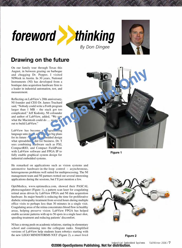
OptiMedica, www.optimedica.com, showed their PASCAL photocoagulator (Figure 1), a pattern scan laser for coagulating retinal areas driven by LabView FPGA and NI data acquisition hardware. Its major benefit is reducing the time for proliferative diabetic retinopathy treatment from several hours during multiple office visits to perhaps less than 30 minutes in a single visit. Coagulating areas of the retina concentrates blood flow in healthy areas, helping preserve vision. LabView FPGA has helped enable accurate patterns with up to 56 spots in a single laser shot, speeding treatment and reducing patients’ discomfort.
NI has a strong push on academic relations, starting in elementary school and continuing into the collegiate ranks. Simplified versions of LabView help students learn robotics starting with the new LEGO MINDSTORMS NXT (Figure 2), a smart brick
Drawing on the future
I n d u s t r i a l E m b e d d e d S y s t e m s Fall/Winter 2006 / �
Figure 1
Figure 2
©2006 OpenSystems Publishing. Not for distribution.
For Single Print Only
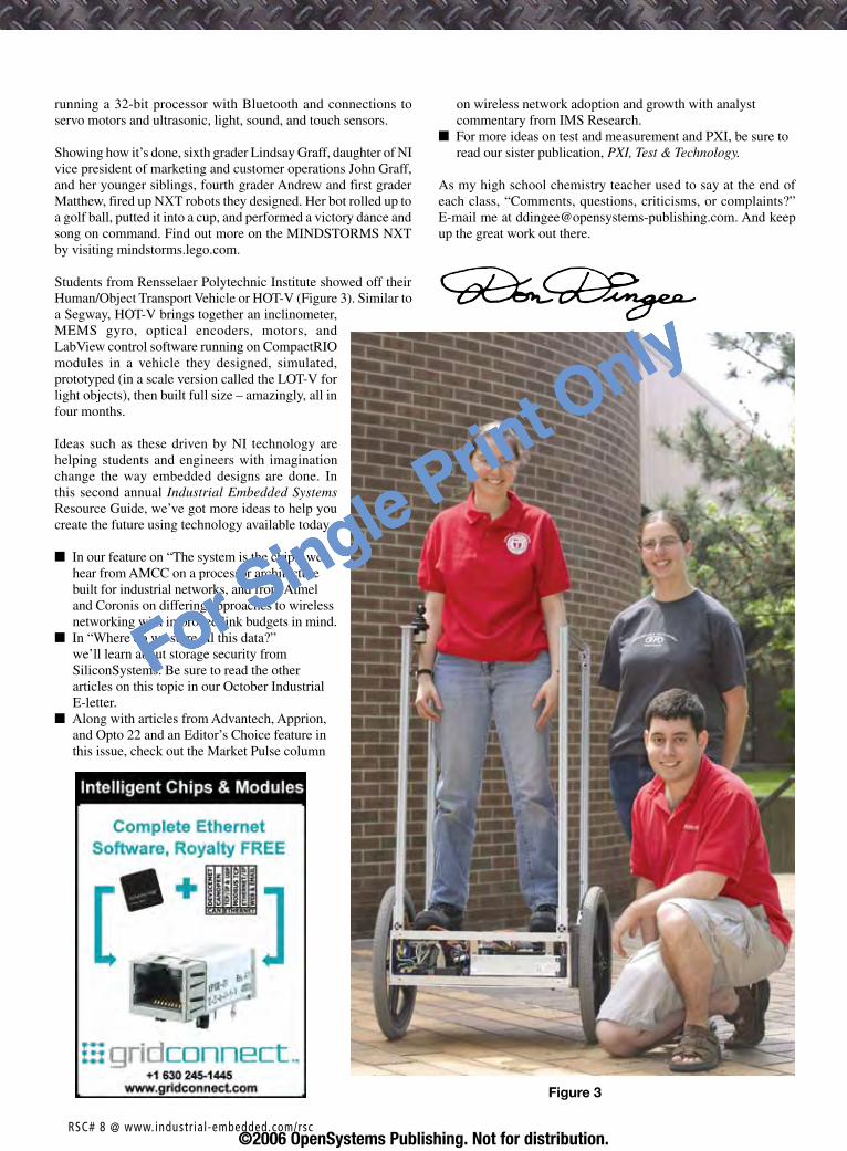
running a 32-bit processor with Bluetooth and connections to servo motors and ultrasonic, light, sound, and touch sensors.
Showing how it’s done, sixth grader Lindsay Graff, daughter of NI vice president of marketing and customer operations John Graff, and her younger siblings, fourth grader Andrew and first grader Matthew, fired up NXT robots they designed. Her bot rolled up to a golf ball, putted it into a cup, and performed a victory dance and song on command. Find out more on the MINDSTORMS NXT by visiting mindstorms.lego.com.
Students from Rensselaer Polytechnic Institute showed off their Human/Object Transport Vehicle or HOT-V (Figure 3). Similar to a Segway, HOT-V brings together an inclinometer, MEMS gyro, optical encoders, motors, and LabView control software running on CompactRIO modules in a vehicle they designed, simulated, prototyped (in a scale version called the LOT-V for light objects), then built full size – amazingly, all in four months.
Ideas such as these driven by NI technology are helping students and engineers with imagination change the way embedded designs are done. In this second annual Industrial Embedded Systems Resource Guide, we’ve got more ideas to help you create the future using technology available today.
In our feature on “The system is the chip,” we hear from AMCC on a processor architecture built for industrial networks, and from Atmel and Coronis on differing approaches to wireless networking with improved link budgets in mind.In “Where do we store all this data?” we’ll learn about storage security from SiliconSystems. Be sure to read the other articles on this topic in our October Industrial E-letter.Along with articles from Advantech, Apprion, and Opto 22 and an Editor’s Choice feature in this issue, check out the Market Pulse column
n
n
n
on wireless network adoption and growth with analyst commentary from IMS Research.For more ideas on test and measurement and PXI, be sure to read our sister publication, PXI, Test & Technology.
As my high school chemistry teacher used to say at the end of each class, “Comments, questions, criticisms, or complaints?” E-mail me at [email protected]. And keep up the great work out there.
n
Figure 3
RSC# � @ www.industr ial-embedded.com/rsc©2006 OpenSystems Publishing. Not for distribution.
For Single Print Only
RSC# � @ www.industr ial-embedded.com/rsc©2006 OpenSystems Publishing. Not for distribution.
For Single Print Only
Editor’s note: Considering wired and wireless networking technologies are featured regularly in Industrial Embedded Systems, we asked IMS Research, a leading market analyst firm, to shed some light on the subject of wireless adoption rates in industrial applications based on their recent research. This commentary presents their viewpoint and key insights.
One to two years ago, Ethernet grabbed most headlines in industrial networking, but that appears to be a done deal. Wireless is now the next big thing – or is it? Although wireless communications has been around for a while, it is still a relatively new concept in most industrial circles. Despite all the buzz about this technology, a recent IMS Research study titled “The World Market for Wireless Communications in Industrial Automation” has concluded that the number of wireless industrial products in the field that conform to an industrial standard is very modest, even with high-percentage growth rates taken into account.
As with Ethernet, much wireless hardware used in industrial systems was originally designed for use in a nice cozy office or home environment and has succeeded in those settings. However, most commercial- and domestic-grade products installed in industrial settings are being used in trial applications – trial is the byword at this time. Most work being carried out with wireless appears to be on an experimental basis, particularly in the factory environment. This leads to the second byword, caution.
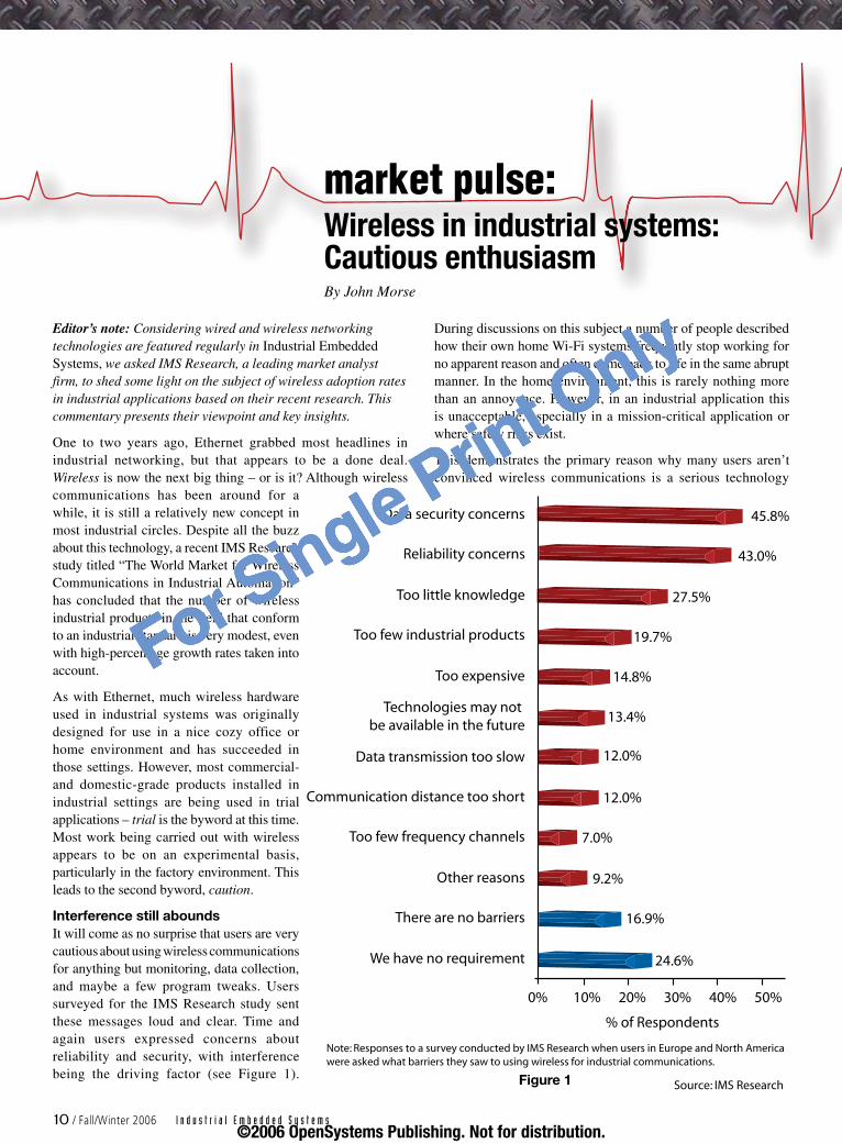
Interference still aboundsIt will come as no surprise that users are very cautious about using wireless communications for anything but monitoring, data collection, and maybe a few program tweaks. Users surveyed for the IMS Research study sent these messages loud and clear. Time and again users expressed concerns about reliability and security, with interference being the driving factor (see Figure 1).
During discussions on this subject a number of people described how their own home Wi-Fi systems frequently stop working for no apparent reason and often come back to life in the same abrupt manner. In the home environment, this is rarely nothing more than an annoyance. However, in an industrial application this is unacceptable, especially in a mission-critical application or where safety risks exist.
This demonstrates the primary reason why many users aren’t convinced wireless communications is a serious technology
market pulse:Wireless in industrial systems: Cautious enthusiasmBy John Morse
We have no requirement
Data security concerns
Reliability concerns
Too little knowledge
Too few industrial products
Too expensive
Technologies may not be available in the future
Data transmission too slow
Communication distance too short
Too few frequency channels
Other reasons
There are no barriers
24.6%
16.9%
9.2%
7.0%
12.0%
12.0%
13.4%
14.8%
19.7%
27.5%
43.0%
45.8%
0% 10% 20% 30% 40% 50%
% of Respondents
Note: Responses to a survey conducted by IMS Research when users in Europe and North America were asked what barriers they saw to using wireless for industrial communications.
Source: IMS Research
10 / Fall/Winter 2006 I n d u s t r i a l E m b e d d e d S y s t e m s
Figure 1
©2006 OpenSystems Publishing. Not for distribution.
For Single Print Only
in the industrial environment. Until this confidence barrier is traversed, the technology will struggle to gain the acceptance it needs to generate significant sales. Real growth in demand will in turn encourage large companies to develop the industrial-grade products required; however, this will take time. During the course of this study, several manufacturers explained they were still digesting the customer requirement for Ethernet products and said they would address wireless development once they saw the demand increase. Users also cited the lack of such industrial-grade products as a barrier to greater wireless communications use.
The safety issue presents a real concern particularly in view of current legislation in Europe, North America, and throughout the industrialized world. Potential litigation costs as well as lost production indicates that wireless communications in industrial systems likely will not enjoy the same rapid growth as industrial Ethernet.
Even with caution, growth is significantHowever, it is not all bad news. Several major industrial automation suppliers such as Siemens, Phoenix Contact, Hirschmann, and Moxa supply wireless products. In addition, numerous smaller companies supply wireless products to process industries, many of which have been using wireless communications for years. Some products are wireless enabled by definition (wireless access points), whereas others are offered as wireless-enabled versions (such as wireless-enabled sensors). Considering wireless products overall, IMS Research forecasts the market will grow in unit shipment terms at a nearly 30 percent compound annual growth rate to 2010. Breaches in the confidence barrier are expected to accelerate sales from 2008 onwards.
Confidence likely will increase as wireless technology standards become established and are considered stable platforms on which new automation systems can be based. As with industrial Ethernet, the question of safety will be addressed in time. This will probably progress from a combination of technological developments and increases in user knowledge. Both will take many years to become established, with technological developments likely to be spearheaded by the organizations managing wireless standards. User knowledge probably will grow with the need to know as the pressures of increased efficiency and productivity dictate. Cost savings can be significant in situations when wireless technology can cover long distances where cables would normally be laid. However, cost savings does not always encourage wireless communications use. The flexibility wireless can provide is often a major factor, allowing flexible component positioning and the ability to make changes simply and quickly.
Implementation choices varyThe IMS Research report also examined the component form factor (silicon approach) manufacturers employed or planned to employ in the future when wireless enabling their products. The three options considered were:
Use wireless modules containing all the necessary components or some kind of dongleICs straight onto the PCBEmbed the functionality into existing devices
n
n
n
Conclusions varied greatly among product groups. However, in view of high product development costs and relatively low numbers produced specifically for industrial applications, only products employing devices manufactured in commercial quantities take the embedded route. Typical industrial products that fall into this category include industrial PCs, rugged mobile computers, and the more complex human machine interface. For other products, the module or IC approach appeared to be preferred, allowing wireless connectivity to be offered as an option at extra cost, of course.
Most agree that wireless communications in the industrial environment eventually will become commonplace and that the concerns of today will merely mark another milestone in this fast-moving sector of the industrial automation industry.
John Morse is a senior market analyst with IMS Research. To purchase this or other industrial market studies, contact:
IMS Research6 Regent Park Booth Drive WellingboroughNN8 6GR EnglandTel: +44 (0)1933 40 22 55 E-mail: [email protected]: www.imsresearch.com
COTS I/O Solutions for:IndustryPack®, PMC, CompactPCI, PCI
with Outstanding Software Support.
TEWS TECHNOLOGIES LLC: 9190 Double Diamond Parkway, Suite 127·Reno, NV 89521/USAPhone: +1 (775) 850 5830·Fax: +1 (775) 201 0347·E-mail: [email protected]
TEWS TECHNOLOGIES GmbH: Am Bahnhof 7·25469 Halstenbek/GermanyPhone: +49 (0)4101-4058-0·Fax: +49 (0)4101- 4058 -19·E-mail: [email protected]
CPU CarriersIP and PMC CarriersEthernetCommunicationCAN BusField BusDigital I/OAnalog I/OPC Card/CardBusMotion ControlMemoryUser-programmable FPGA
© 2
006
TE
WS
TE
CH
NO
LOG
IES
Gm
bH,
all r
ight
s re
serv
ed.
Indu
stry
Pac
k is
a r
egis
tere
d tr
adem
ark
of S
BS
Tec
hnol
ogie
s,
Inc.
All
othe
r tr
adem
arks
men
tione
d ar
e pr
oper
ty o
f th
eir
resp
ectiv
e ow
ners
.
VxWorksLinuxWindowsLynxOSQNXOS-9
w w w . t e w s . c o m
0883_TW_1-4-AZ_USA_OPVerlag 03.08.2006 12:32 Uhr Seite 1
RSC# 11 @ www.industr ial-embedded.com/rsc
©2006 OpenSystems Publishing. Not for distribution.
For Single Print Only

Finally, the network is the microprocessor. Our coverage of the latest in System-on-Chip (SoC) technology starts with a look at key points of an industrial SoC architecture and features designed for industrial control networks in an integrated device. Kyle highlights flexible memory architecture, the integrated IEEE 1588 timing protocol, and a configurable timing block.
A revolution is quietly overtaking the industrial and general-purpose microcontroller (MCU) markets. Indeed, networking has found its way into even the most deeply embedded devices in the industrial, scientific, and commercial market segments. What was once the exclusive domain of 8-bit and 16-bit MCUs performing only a few tasks embedded in isolated equipment is now a field of applications calling for higher-performing 32-bit SoCs to handle the additional network connectivity tasks.
A new class of SoC architecture is emerging, one that fits the new challenges for an industrial networking device. These challenges include scalable data and I/O processing, synchronized networking, and configurable timing.
Scalable data and I/O processing Traditional sub-100 MHz 32-bit RISC-based and DSP-based MCUs, burdened with their slow on-chip buses and flash, tend to struggle under this new additional connectivity workload. Even if these traditional flash-based MCUs can be pushed to higher clock speeds, the on-chip flash and narrow 32-bit buses do not scale – the application simply waits faster with little real data and I/O throughput improvement.
An SoC built for data and I/O traffic should have both a high-performance processor and busing capable of handling the heavy DMA I/O traffic that typically occurs in demanding embedded and industrial applications, which now require connectivity. DMA should be optimized to not interfere with core processor operations.
Ideally, an SoC architecture would scale, enabling single-chip solutions using on-chip memory, or multichip solutions with additional external memory. Using on-chip SRAM instead of traditional flash would help increase performance, lower power,
and reduce cost. Similarly, supporting external Pseudo Static RAMs (PSRAMs) and CellularRAM (low-power and bursting RAM products already used pervasively in mobile markets) would enable system designers to cost effectively scale memory solutions, allowing a single SoC architecture to service a range of designs.
In sync with networkingKey connectivity peripherals for an industrial networking SoC include Ethernet, USB, and CAN, enabling designers to build flexible networking gateways. Directly integrating these peripherals with elements such as A/D and D/A converters and timers in an SoC device for industrial applications is a given.
A new standard building momentum is the IEEE 1588 Precision Timing Protocol (PTP). An IEEE 1588 controller provides precise, hard, real-time control, trigger, and time stamping of Ethernet packets and I/O events. IEEE 1588 is rapidly gaining popularity as an open standard synchronization protocol for taming Ethernet and TCP/IP for use in precisely synchronizing events (for example, sensor capture and task and event triggering) among literally thousands of devices deployed across any LAN hierarchy.
IEEE 1588 applies not just in the industrial market that initiated this IEEE standard, but in any market segment needing cost-effective network synchronization and event triggering.
Timing is everythingTraditional timer controllers are architected and hardwired by a chip designer to a particular preconceived notion of how a timer should be built and used in a particular application. Configurable timer blocks, on the other hand, allow system designers to mimic virtually any type of existing timer architecture or create their own custom mix of timer elements.
PSRAMs and CellularRAMsPseudo Static RAMs (PSRAMs) generally combine the features of DRAM and SRAM to create higher-density, lower-power devices. CellularRAM, the trademark name for Micron’s PSRAM device with an asynchronous/page and burst flash interface, offers compatibility with flash interfaces, higher data throughput, and low active and standby current levels compared to DRAM devices. Learn more at www.cellularram.com.
SoCarchitecturetacklesindustrialnetworkingBy Kyle Harper
The system is the chip: AMCC
12 / Fall/Winter 2006 I n d u s t r i a l E m b e d d e d S y s t e m s©2006 OpenSystems Publishing. Not for distribution.
For Single Print Only

RSC# 1� @ www.industr ial-embedded.com/rsc©2006 OpenSystems Publishing. Not for distribution.
For Single Print Only
A timer block should enable system designers to construct complex timing functions requiring deterministic behavior without resorting to specialized complex scripting or DSP programming languages (and hard-to-find specialized expertise). It should offload the CPU and software significantly in even the most complex timing algorithms, thus freeing up the CPU and bus bandwidth for use elsewhere in the application. A few examples of these complex real-time functions in industrial applications include:
Pulse Width Modulation (PWM) and space vector PWM functions with nonoverlap timesQuadrature encoder sensing and control Programmable deadband intervals Pulse period measurement 48-bit input capture function48-bit output compare function
Also, these timers should coordinate with the IEEE 1588 PTP network clock, allowing the system designer to time-stamp and trigger events across an entire IEEE 1588 PTP network of nodes. This architecture synchronizes nodes simply, precisely, and accurately without CPU, software, and interrupts involved in the critical path, thus avoiding synchronization jitter.
Architecture meets siliconThese architectural points are implemented in the AMCC PPC405EZ, an easily programmable general-purpose PowerPC 405-based microprocessor that offers an ideal upgrade path for applications with 8-bit, 16-bit, RISC, or DSP MCUs needing
n
n
n
n
n
n
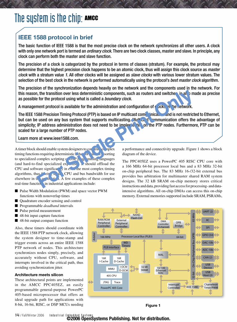
a performance and connectivity upgrade. Figure 1 shows a block diagram of the device.
The PPC405EZ uses a PowerPC 405 RISC CPU core with a 166 MHz 64-bit processor local bus and a 83 MHz 32-bit on-chip peripheral bus. The 83 MHz 16-/32-bit external bus provides bus arbitration for multimaster shared RAM system designs. The 32 kB SRAM on-chip memory stores critical instructions and data, providing fast access for processing- and data-intensive algorithms. All on-chip DMAs can access this on-chip memory. External memories supported include SRAM, PSRAMs,
IEEE 1588 protocol in briefThe basic function of IEEE 1588 is that the most precise clock on the network synchronizes all other users. A clock with only one network port is termed an ordinary clock. There are two clock classes, master and slave. In principle, any clock can perform both the master and slave function.
The precision of a clock is categorized by the protocol in terms of classes (stratum). For example, the protocol may determine that the highest precision clock happens to be an atomic clock, thus will assign this clock source as master clock with a stratum value 1. All other clocks will be assigned as slave clocks with various lower stratum values. The selection of the best clock in the network is performed automatically using the protocol’s best master clock algorithm.
The precision of the synchronization depends heavily on the network and the components used in the network. For this reason, the transition over less deterministic components, such as routers and switches, is also made as precise as possible for the protocol using what is called a boundary clock.
A management protocol is available for the administration and configuration of clocks in the network.
The IEEE 1588 Precision Timing Protocol (PTP) is based on IP multicast communication and is not restricted to Ethernet, but can be used on any bus system that supports multicasting. Multicast communication offers the advantage of simplicity; IP address administration does not need to be implemented on the PTP nodes. Furthermore, PTP can be scaled for a large number of PTP nodes.
Learn more at www.ieee1588.com.
RAM/ROMPeripheralController
ExternalPeripheralController
NANDFlash Ctrl
Arb
iter
166 MHz Processor Local Bus (PLB3) 64-bit
DMAController
(4 channel)
OPB Bridge
PLB Interface
WD Timers
16KI-Cache
16KD-Cache
MMUI-OCM
D-OCM
405 CPU
JTAG Trace
PowerPC 405 Core
32 kBSRAM
MAL
10/100Ethernet
MAC
UART (2)
IIC
SPI
GPIO (54)
DAC-10b
ADC-10b
CAN (2)
USBDevice
USBHost (2)
InterruptController IEEE 1588
ChameleonTimer/PWM
32-b
it
On
-Ch
ip P
erip
her
al B
us
(OPB
) 83
MH
z
The system is the chip: AMCC
1� / Fall/Winter 2006 I n d u s t r i a l E m b e d d e d S y s t e m s
Figure 1
©2006 OpenSystems Publishing. Not for distribution.
For Single Print Only
CellularRAMs, ROM, NOR and NAND flash, as well as SPI- or I2C-based NVRAMs. Indeed, it is possible to build a complete high-performance embedded solution with just the on-chip 32 kB SRAM plus one NVRAM device (NOR, NAND, SPI, or I2C). Systems ranging from simple to multimaster configurations can be built.
The PPC405EZ’s connectivity package consists of one Fast Ethernet port with an integrated IEEE 1588 PTP controller, three USB 1.1/2.0 Full Speed compatible ports with integrated PHYs, and two CAN 2.0b ports. Features include one 8-input 10-bit 300 kSps ADC, one 10-bit 30 MSps DAC, and a configurable auto-reloading 15-channel Chameleon Timer/PWM controller that significantly offloads the CPU and software for complex timing and waveform generation. The IEEE 1588 PTP controller is fully integrated directly into the analog functions, the Chameleon Timer, and other on-chip functions to optimize performance and eliminate CPU involvement in capturing, triggering, and time-stamping deterministic real-time events in devices that are local or deployed across entire networks.
Tighter event control With this type of architecture, gone are the days when a system designer/programmer would struggle with synchronizing just a few real-time I/O events across a single chip or even across a single board, let alone I/O events across an entire network. Using an architecture optimized for networking – delivering scalable data and I/O processing, synchronized networking, and configurable timing – designers can control tightly synchronized I/O events across an entire network of devices. IES
Kyle Harper is strategic marketing manager for AMCC’s Embedded Markets. He has worked 23 years as an engineer and business manager developing
high-performance microprocessors and embedded systems ranging from desktop computers to wireless and portable applications, and has published more than 40 papers and presentations. Prior to joining AMCC, he held a variety of positions with Motorola and Freescale Semiconductor. Kyle received a BS in Computing Science from Texas A&M University and an MBA from the University of Texas at Austin.
To learn more, contact Kyle at:
AMCC7501 N. Capital of Texas Hwy., Suite A-200Austin, TX 78731Tel: 512-372-1713 E-mail: [email protected]: www.amcc.com
Go www.amcc.com/Embedded/
The system is the chip: AMCC
I n d u s t r i a l E m b e d d e d S y s t e m s Fall/Winter 2006 / 15
RSC# 1� @ www.industr ial-embedded.com/rsc
©2006 OpenSystems Publishing. Not for distribution.
For Single Print Only

Networking Systems-on-Chip (SoCs) are becoming increasingly important, and ZigBee/802.15.4 systems are not all created equal. Chris describes considerations for choosing solutions and discusses differences in single-chip versus multichip solutions.
ZigBee is a low data rate, wireless networking standard based on IEEE 802.15.4 that can eliminate the need for hard-wiring industrial control networks. All ZigBee networks are 802.15.4 networks, with the ZigBee standard providing security and application layers that ensure interoperability between equipment from different vendors. Interoperability is probably less of an issue in industrial control than it is in security, lighting, or climate control applications. This distinction is important because the ZigBee standard is still evolving, while 802.15.4 is simpler to implement and ready to go now. Figure 1 shows the 802.15.4 hardware/software solution.
Networks, whether wired or wireless, provide communication for industrial control applications, but generally do not control a chemical or manufacturing process. Compared to WLAN, WiMAX, Bluetooth, and so on, ZigBee/802.15.4 networks are different – their primary application is the industrial control
application. The dual sensor-plus-network nature of 802.15.4 applications adds an extra layer of complexity to the design challenge, compounded by the fact that most industrial control engineers are not RF design experts. They may not know which RF parameters are most important, how to evaluate an 802.15.4 software stack, or how to interface the controller with the radio.
Fortunately, many 802.15.4 vendors, including Atmel, Jennic, Texas Instruments, Freescale, and Ember, are assembling integrated, system-level solutions that include the 802.15.4 radio, controller, all interfaces and 802.15.4/ZigBee software stacks, and development kits. Among these, designers still need some criteria for evaluating which solution best meets cost, performance, topology, and flexibility constraints.
Six basic issues affect the choice of an 802.15.4 solution:
How simple or complex the network must be Choosing the 802.15.4 radio frequency for the applicationRF parameters and system cost The architecture of the Media Access Controller (MAC) Should it be a single-chip or two-chip solutionFactors affecting power consumption
Network complexitySeveral types of network configurations can be implemented under the 802.15.4 and ZigBee umbrella: point-to-multipoint (star) networks, tree networks, and mesh networks. Star networks (Figure 2), typically used for low-cost gaming or entertainment center control, are the simplest to implement and require the least amount of code for setup and control. They are usually limited in the quantity of nodes and coverage.
Tree networks are used for applications such as access or industrial control sensing. Since they allow more nodes, they can cover a larger area than star networks. However, they may suffer from latency effects that can cause unacceptable data delays for critical applications. Tree networks may be subject to critical node failure leading to system failure, and usually need more code to implement than multipoint systems.
1.2.3.4.5.6.
Balancing the ZigBee/802.15.4 link budget
By Chris Baumann
APPLICATON/PROFILES
APPLICATON FRAMEWORK
NETWORK/SECURITYLAYERS
MEDIA ACCESS CONTROLLAYER
PHYSICAL LAYER
ZigBeeor OEM
ZigBeeAlliancePlatform
IEEE802.15.4
Figure 1
The system is the chip: Atmel
1� / Fall/Winter 2006 I n d u s t r i a l E m b e d d e d S y s t e m s©2006 OpenSystems Publishing. Not for distribution.
For Single Print Only

Mesh networks (Figure 3) represent the highest level of 802.15.4/ZigBee configuration and require the most network level code. Mesh networks can self-heal critical node failures, making them ideal for large building control systems or wide area sensing. They are by far the most difficult 802.15.4/ZigBee networks to design and implement.
In terms of system implementation, the simpler the network, the better. A simpler network allows the design team to focus on the industrial control application rather than the network. For the vast majority of industrial control applications, star or tree networks should suffice. These simpler networks do not require a full ZigBee implementation and are therefore easier to build and integrate into the application using IEEE 802.15.4 alone. Extremely large and/or self-healing networks require ZigBee to manage the mesh networking functionality.
868 MHz, 902 MHz, or 2.4 GHz The 802.15.4 standard defines three radio frequencies: 868 MHz (available only in the European Union), 902 MHz (available in the United States), and 2.4 GHz (worldwide). Table 1 summarizes each radio frequency’s data rate.
Frequency Data rate Channels868 MHz 20 mbps 1902 MHz 40 mpbs 162.4 GHz 250 mbps 40
Table 1
The majority of 802.15.4 radios on the market today operate in the 2.4 GHz band. This unlicensed frequency is available all over the world, so an application that requires worldwide interoperability should definitely use the 2.4 GHz band.
However, 2.4 GHz radios have some disadvantages. For one, the 2.4 GHz band is crowded. Bluetooth, WLAN, microwave ovens, and garage door openers all operate in this unlicensed band, increasing the likelihood of interference. There is virtually no interference in the 868/902 MHz bands except for some older cordless phones and keyboard mice. The higher sensitivity (-92 dBm versus -85 dBm) and the inherently better wall penetration of the 868/902 MHz radios allow them to be spaced farther apart, potentially lowering the cost of the network. At the same distance, lower-band radios also consume less power than 2.4 GHz radios due to their better sensitivity and wall penetration.
The 900 MHz band is not widely available in the European Union, thus it is not practical for applications that must be interoperable between the United States and Europe. However, the relative emptiness of this band in non-European geographies, combined with low power and high sensitivity make 900 MHz radios good candidates for industrial or other applications that do not need global interoperability.
APPLICATON/PROFILES
APPLICATON FRAMEWORK
NETWORK LAYER
MEDIA ACCESS CONTROLLAYER
PHYSICAL LAYER
ZigBeeor OEM
ZigBeeAlliancePlatform
IEEE802.15.4
Dev
Dev
Coord
Dev
Dev
Rad
ioC
on
tro
ller
Figure 2APPLICATON/PROFILES
APPLICATON FRAMEWORK
NETWORK LAYER
MEDIA ACCESS CONTROLLAYER
PHYSICAL LAYER
ZigBeeor OEM
ZigBeeAlliancePlatform
IEEE802.15.4
Dev
Dev
Rtr
Dev
Dev
Rad
ioC
on
tro
ller
Dev
Dev
Dev
DevDev
Dev
Rtr
Rtr
Figure 3
The system is the chip: Atmel
I n d u s t r i a l E m b e d d e d S y s t e m s Fall/Winter 2006 / 1�©2006 OpenSystems Publishing. Not for distribution.
For Single Print Only
RF parameters and system costsIt is probably not necessary to be an RF expert to implement an 802.15.4 industrial control application. However, some radio-related issues have significant implications for system cost: receiver sensitivity, transmit power, and the link budget.
Receiver sensitivity is the minimum power in decibels (dBm) at which a radio can reliably receive data. A large negative dBm number indicates higher receiver sensitivity. The 802.15.4 standard specifies a minimum receiver sensitivity of -85 dBm for 2.4 GHz radios and -92 dBm for 900 MHz radios. All 802.15.4 radio vendors exceed these standards, offering radios with receiver sensitivities that range between -90 dBm and -100 dBm. Higher sensitivity allows radios to be spaced farther apart, directly cutting system costs. Higher sensitivity also can reduce or eliminate the need for power amplifiers used to boost signal strength when receiver sensitivity is low.
Very small differences in sensitivity result in very large differences in the number of radios required. Although 6 dBm may not seem like much, improving the receiver sensitivity of an 802.15.4 radio from -94 dBm to -100 dBm effectively doubles its line-of-sight range and allows half as many radios to cover the same area. For example, if a radio with -94 dBm receiver sensitivity has a 100-meter range, increasing that sensitivity to -100 dBm will increase its range to 200 meters.
Transmit power drives radio range – the higher the power, the longer its range for a desired signal strength. The 802.15.4 standard requires radios to have a minimum output power of -3 dBm, or 0.5 mW. Radios on the market today have output power of between 0 dBm (1 mW) and 3 dBm (2 mW).
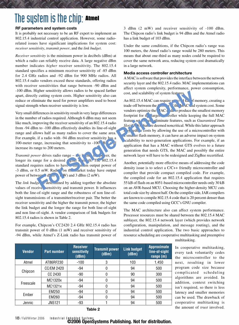
The link budget is determined by adding together the absolute values of receiver sensitivity and transmit power. It influences both the line-of-sight range and the robustness of non line-of-sight transmissions of a transmitter/receiver pair. The better the receiver sensitivity and the higher the transmit power, the higher the link budget and the longer the range for both line-of-sight and non line-of-sight. A vendor comparison of link budgets for 802.15.4 radios is shown in Table 2.
For example, Chipcon’s CC2420 2.4 GHz 802.15.4 radio has transmit power of 0 dBm (1 mW) and receiver sensitivity of -94 dBm, while Atmel’s Z-Link radio has transmit power of
3 dBm (2 mW) and receiver sensitivity of -100 dBm. The Chipcon radio’s link budget is 94 dBm and the Atmel radio has a link budget of 103 dBm.
Under the same conditions, if the Chipcon radio’s range was 100 meters, the Atmel radio’s range would be 280 meters. This means that about one-third as many nodes could be required to cover the same network area, reducing system cost dramatically in a large network.
Media access controller architectureA MAC is software that provides the interface between the network security layer and the 802.15.4 radio. MAC implementations can affect system complexity, performance, power consumption, cost, and scalability of system features.
An 802.15.4 MAC can require up to 24 kB of memory, creating a trade-off between the fullness of the MAC and system cost. Some vendors optimize the MAC code to produce the smallest memory footprint for the target controller while keeping the full MAC feature set. Others eliminate features, such as Guaranteed Time Slot (GTS), that are deemed noncritical. While this latter approach may reduce costs by allowing the use of a microcontroller with a smaller flash memory, it can have an adverse impact on system scalability to next-generation applications. For example, if an application that has a MAC without GTS evolves to a future generation that needs GTS, the MAC and possibly the entire network layer will have to be redesigned and ZigBee recertified.
Another, potentially more effective means of addressing the code density issue is to select a C/C++ friendly microcontroller and compiler that provide compact compiled code. For example, the compiled code for an 802.15.4 application that requires 55 kB of flash on an 8051-based microcontroller needs only 30 kB on an AVR-based MCU. Choosing the higher-density MCU cuts total code size by almost half. On the compiler side, IAR compilers are known to compile 802.15.4 code that is 20 percent denser than the same code compiled using GCC’s GNU compiler.
The MAC architecture also can affect system performance. Processor resources must be shared between the 802.15.4 MAC sublayer, the 802.15.4 network layer (which provides network configuration, manipulation, and message routing), and the industrial control application. The two basic approaches to resource scheduling are cooperative multitasking and preemptive
multitasking.
In cooperative multitasking, every task voluntarily cedes the microcontroller to the next, resulting in lower program code size because compl ica ted schedul ing algorithms are avoided. In addition, context switching isn’t required, so there is less latency and smaller memories can be used. The drawback of cooperative multitasking is the amount of trust involved.
Vendor Part numberReceiver
sensitivity (dBm)
Transmit power (dBm)
Link budget (dBm)
Approximate line-of-sight range (m)
Atmel AT86RF230 -100 3 103 1,450
ChipconCC/EM 2420 -94 0 94 500
CC 2430 -90 0 90 300
FreescaleMC1320x -94 0 94 500MC1321x -94 0 94 500
EmberEM250 -94 0 94 500EM260 -94 0 94 500
Jennic JN5121 -93 1 94 500
Table 2
The system is the chip: Atmel
18 / Fall/Winter 2006 I n d u s t r i a l E m b e d d e d S y s t e m s©2006 OpenSystems Publishing. Not for distribution.
For Single Print Only
Each process must regularly give processor time to other processes. A poorly designed program or a hung task can effectively bring the system to a halt. Designing a system so that it avoids these pitfalls can be onerous and may result in irregular or inefficient use of system resources.
Preemptive multitasking initiates a context switch that satisfies the scheduling policy’s priority constraint. It preempts the active task and prevents a hung task from halting the system. This requires more code and introduces latencies into the system. While cooperative multitasking gives the application designer control over scheduling, preemptive multitasking gives scheduling control to the operating system and software stack. A typical 802.15.4 application will not usually need this level of protection and can generally go with the smaller code size and lower latency of a cooperative multitasking scheme.
Single-chip or chipset Although it may seem intuitive that a single-chip solution would be preferable to a multichip solution, in 802.15.4 applications, this isn’t the case because there are different types of nodes for different functions. Full function devices act as gateway servers or routers and can be quite complex, while Reduced Function Devices (RFDs) can be as simple as a sensor or a switch. Obviously the amount of processing, code size, peripherals, context switching, and memory required will be much more substantial than for an end node with a sensor.
The two single-chip offerings on the market today are overkill for many end nodes and may not have the horsepower to execute the industrial control application itself, mandating additional controllers for the primary application and increasing system complexity substantially. Someday there will be single-chip 802.15.4 devices that can cost effectively address all the various node types, but for now it is preferable to select an 802.15.4 vendor offering multiple microcontrollers with a range of memory densities optimized for their radios.
Controller and full function nodes, such as those in gateway servers or electrical equipment, are usually hardwired to a power source. Reduced function nodes,
connected to sensors and switches, are usually battery powered. All battery-operated nodes should have a very long battery life – if possible longer than the life of the end product. The ZigBee standard mandates a two-year battery life for battery-powered nodes, and longer is always better. Imagine how annoying (not to mention expensive) it would be to replace all the sensors and switches in a process control system every few years.
A wide variety of vendors offer 802.15.4/ZigBee radios or controllers or both. These can be integrated on a single chip or come
as a complete chipset. Any engineer who is not an expert in the integration of radios with controllers (that is, most engineers) should probably choose a complete solution from a single vendor. This path will vastly simplify product development and will give engineers much more freedom to develop the differentiating features of the end application.
Using a single-chip solution provides a small footprint and may lower power consumption. However, it also weds the engineer to a microcontroller that might not be the best for the target application.
The system is the chip: Atmel
RSC# 1� @ www.industr ial-embedded.com/rsc
©2006 OpenSystems Publishing. Not for distribution.
For Single Print Only
The embedded controller may not have all the necessary peripherals. Furthermore, although the embedded controller may have enough flash memory for the first-generation design, it may not offer a migration path to devices with bigger memories to accommodate the addition of new, software-based features. If there is no migration path to a controller with 128 kB or even 256 kB of flash, external chips may be required, increasing system cost, board size, and power consumption. Conversely, single-chip solutions do not offer the option of reducing costs by opting for a controller with smaller flash or fewer peripherals.
The 802.15.4/ZigBee market is in its infancy. Nobody knows yet which applications will get traction in the market or how those applications will evolve. There are probably dozens of applications that no one has even imagined. Therefore, at present, it makes sense to design an application with a discrete radio coupled with a family of microcontrollers that provides the flexibility to let applications evolve as the market evolves.
Power consumption considerationsReduced function 802.15.4 nodes are often battery powered. Any battery-powered node should have a battery life that outlasts the system itself because changing the battery inside a piece of industrial equipment, pipeline, or flow control valve can bring the system to a halt and be very expensive.
The factors most affecting power consumption include:
Supply voltages of the radio and microcontrollerActive current drawn by the radio and microcontrollerClock frequency at which the controller operatesNumber of external components required in the system (particularly power amplifiers) Code size, as it affects the MCU clock frequency
This indicates engineers should use low-voltage devices, avoid the use of power amplifiers, and strive for compact code. A less obvious factor, sleep-mode power consumption, is perhaps more important than these concerns. RFDs are likely to spend 99.9 percent of their time in sleep mode, waking up periodically for a few microseconds to check a sensor or poll other radios, then going right back to sleep. As a result, the total power consumption of an RFD is likely to approach sleep-mode power consumption. Vendors and engineers tend to emphasize active power consumption, and sleep-mode power consumption may be buried deep inside the data sheet.
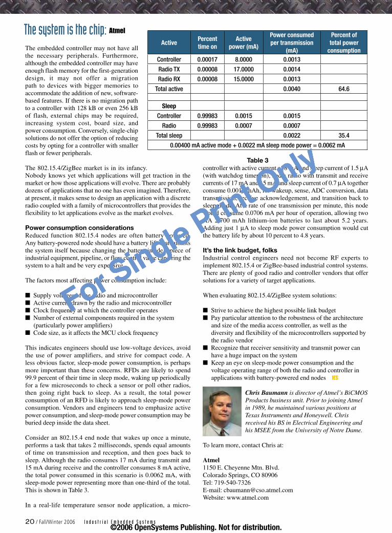
Consider an 802.15.4 end node that wakes up once a minute, performs a task that takes 2 milliseconds, spends equal amounts of time on transmission and reception, and then goes back to sleep. Although the radio consumes 17 mA during transmit and 15 mA during receive and the controller consumes 8 mA active, the total power consumed in this scenario is 0.0062 mA, with sleep-mode power representing more than one-third of the total. This is shown in Table 3.
In a real-life temperature sensor node application, a micro-
nnnn
n
controller with active current of 8 mA and sleep current of 1.5 µA (with watchdog timer on), and a radio with transmit and receive currents of 17 mA and 15 mA and sleep current of 0.7 µA together consume 0.0011 mAh, for wakeup, sense, ADC conversion, data transmission, receive acknowledgement, and transition back to sleep mode. At a rate of one transmission per minute, this node would consume 0.0706 mA per hour of operation, allowing two AA 2,700 mAh lithium-ion batteries to last about 5.2 years. Adding just 1 µA to sleep mode power consumption would cut the battery life by about 10 percent to 4.8 years.
It’s the link budget, folksIndustrial control engineers need not become RF experts to implement 802.15.4 or ZigBee-based industrial control systems. There are plenty of good radio and controller vendors that offer solutions for a variety of target applications.
When evaluating 802.15.4/ZigBee system solutions:
Strive to achieve the highest possible link budgetPay particular attention to the robustness of the architecture and size of the media access controller, as well as the diversity and flexibility of the microcontrollers supported by the radio vendorRecognize that receiver sensitivity and transmit power can have a huge impact on the systemKeep an eye on sleep-mode power consumption and the voltage operating range of both the radio and controller in applications with battery-powered end nodes IES
Chris Baumann is director of Atmel’s BiCMOS Products business unit. Prior to joining Atmel in 1989, he maintained various positions at Texas Instruments and Honeywell. Chris received his BS in Electrical Engineering and his MSEE from the University of Notre Dame.
To learn more, contact Chris at:
Atmel1150 E. Cheyenne Mtn. Blvd. Colorado Springs, CO 80906Tel: 719-540-7326 E-mail: [email protected]: www.atmel.com
nn
n
n
ActivePercent time on
Active power (mA)
Power consumed per transmission
(mA)
Percent of total power
consumptionController 0.00017 8.0000 0.0013
Radio TX 0.00008 17.0000 0.0014
Radio RX 0.00008 15.0000 0.0013
Total active 0.0040 64.6
Sleep
Controller 0.99983 0.0015 0.0015
Radio 0.99983 0.0007 0.0007
Total sleep 0.0022 35.4
0.00400 mA active mode + 0.0022 mA sleep mode power = 0.0062 mA
The system is the chip: Atmel
Table 3
20 / Fall/Winter 2006 I n d u s t r i a l E m b e d d e d S y s t e m s©2006 OpenSystems Publishing. Not for distribution.
For Single Print Only

Editor’s Choice Products
Editor’s Choice Products are drawn from OSP’s product database and press releases. Vendors may add their new products to our website at www.opensystems-publishing.com/vendors/submissions/np/ and submit press releases at www.opensystems-publishing.com/news/submit. OSP reserves the right to publish products based on editors’ discretion alone, and does not guarantee publication of any product entries.
BACnet browsing shows the full pictureBACnet devices have become extremely popular in building automation networks, con-necting systems such as heating, ventilating, and air-conditioning control; lighting control; access control; and fire detection systems. But managing a wide array of devices from differ-ent manufacturers on a single network can be tricky. The BACnet browser within the Insight Revision 3.7 graphical workstation software from Siemens provides enhanced capabilities that enable facility managers and systems operating staff to easily acquire comprehen-sive information about the state of devices and device communication within a BACnet network with an APOGEE modular equipment controller or modular building controller.
Through Insight, users (depending on their level of access) can write properties, import objects, reinitialize devices, or engage device communication controls. Regardless of device manufacturer, users have access to detailed data such as vendor name, device status, protocol revisions, and a list of supported objects and services. Users can then read and write to any object properties the device permits for complete command and control of the network.
Siemens www.usa.siemens.com/bacnet RSC# 31526
Got a USB port? Start logging dataSometimes, the job calls for data logging in a remote location. Setting up big data loggers, power sup-plies, and sophisticated software is painful – it’d be much easier to just plug something simple into a laptop and go. But accuracy and proven measurement technology are still required. With a new family of data loggers from National Instruments, engineers get all this and more.
The low-cost National Instruments USB-6210, USB-6211, USB-6215, and USB-6218 devices draw power directly from the USB port and therefore do not require an external power supply. They feature NI signal streaming technology, a new technology for high-speed data streaming over the USB cable, which leads to four times improvement in sampling rate over previ-ous NI bus-powered multifunction data acquisition devices. They also feature M Series technology, including NI-MCal, a revolutionary design for calibration at every input range that improves measurement accuracy, and the NI-PGIA 2 family of programmable-gain instrumentation amplifiers, which dramatically reduces settling time to ensure accurate measurements even at the fastest scanning rates.
National Instrumentswww.ni.com RSC# 31527
GigE, camera, Linux – action!Vision systems used to mean expensive hardware and complicated software. Today, designers can get a camera on their Ethernet network in minutes. Prosilica’s GE-Series Gigabit Ethernet cameras offer high-performance digital imaging for applications in machine vision, industrial inspection, traffic moni-toring, and public security. The GE-Series sends noncompressed images rang-ing from VGA at 200 frames per second up to 4-megapixel resolution running 15 frames per second over standard Gigabit Ethernet hardware with cable lengths up to 100 meters long. The GE-Series are among the first machine vision cameras shipping that conform to the Automated Imaging Association GigE Vision standard.
The Linux GigE Vision SDK provides programmers the means to control and capture images from Prosilica GE-Series cameras. The SDK also includes sample code to help programmers more easily integrate and use Prosilica’s cameras in their Linux-based applications running on either x86 or PowerPC systems, making it a great choice for embedded designs.
Prosilicawww.prosilica.com RSC# 31528
RFID for the rugged industrial typeRadio Frequency Identification (RFID) tags will soon be ubiquitous on items in your friendly big-box retail store where condi-tions are fairly benign. In industrial environ-ments, however, conditions may be much more hostile. For example, in food process-ing applications, tags may be partially or completely immersed in liquid or encased in solids, making reading difficult for com-mercial gear.
The Cobalt HF series of RFID readers is designed for exactly this problem – reliable reading of tags in industrial environments. With USB and industrial Ethernet connectivity, these readers integrate a 13.56 MHz RFID antenna with a microprocessor-based controller featuring C-Macro programming. Addressing two of the key concerns with RFID technology for high-speed auto-mated lines, network traffic overload and high-speed local decision making, C-Macros allow host systems to enable local intelligence. The readers support a simultaneous read/write to dozens of tags and anticollision technology for multiple tag-in-field situations. With the antenna and controller in one inte-grated package, setup is quick and easy.
Escort Memory Systemswww.ems-rfid.com RSC# 30074
I n d u s t r i a l E m b e d d e d S y s t e m s Fall/Winter 2006 / 21©2006 OpenSystems Publishing. Not for distribution.
For Single Print Only
Monitoringindustrialconditionswithlong-rangewirelesstechnologyBy Christophe Dugas
Ranges of 200 m indoors and up to 1 km line-of-sight present problems for many wireless industrial networks. Wavenis technology handles these ranges reliably. Christophe explains some of the key points behind Wavenis and previews the next-generation Wavenis System-on-Chip (SoC) solution, which further reduces size and cost.
Each year, the industrial sector suffers billions of dollars in losses due to equipment downtime. The damages are not just confined to reduced productivity, either. Unexpected breakdowns contribute to high repair costs as well as increased risks for injury and serious accidents.
With much at stake, manufacturers are increasingly seeking systems that will enable them to effectively monitor the conditions of their critical assets. Until about 25 years ago, plant personnel conducted condition monitoring primarily using their five senses. The practice was irregular, imperfect, and time consuming. Today, companies such as Pedigree Technologies are using advanced sensor and wireless technologies to effectively predict equipment malfunction, enabling manufacturers to perform preventive maintenance and reduce the negative impact of repair-related downtime.
Headquartered in Fargo, North Dakota, Pedigree Technologies specializes in deploying real-time machine-to-machine asset management solutions for the agribusiness and food processing industry. The company’s latest solution integrates Wavenis wireless sensor networks installed at customer sites with custom back-end software for monitoring and analysis. The sensors collect critical data on temperature, pressure, and vibration from in-plant machines. Pedigree’s platform feeds the data over a custom Internet gateway, delivering it either in a hosted environment or directly to the customer via the Pedigree gateway.
Industry challengeFor many wireless network applications, the lack of an appropriate technology makes it unrealistic to deploy time-saving and convenient solutions in the field. While Ultra Low Power (ULP) and long-range solutions are well adapted to
citywide networks and large industrial sites, solutions such as those Pedigree developed are subject to severe performance constraints that current Radio Frequency (RF) standards such as High-Performance Radio LAN (HIPERLAN), Digital Enhanced Cordless Telecomm (DECT), IEEE 802.11, Bluetooth, and more recently ZigBee cannot effectively address. Connectable devices must be installed in hard-to-reach places, often transmitting data over long distances. Devices must also subsist on extremely low power resources, maintaining battery-powered operation for several years without human intervention. Lastly, ambient conditions of industrial situations pose technical challenges for deploying wireless networks as sites are already loaded with wireless technologies such as Wi-Fi, Bluetooth, and other proprietary protocols, not to mention interference from electrical sources, steel, and concrete.
When designing their latest solution, Pedigree chose fully realized devices such as those shown in Figure 1, utilizing the
The system is the chip: Coronis
22 / Fall/Winter 2006 I n d u s t r i a l E m b e d d e d S y s t e m s©2006 OpenSystems Publishing. Not for distribution.
For Single Print Only
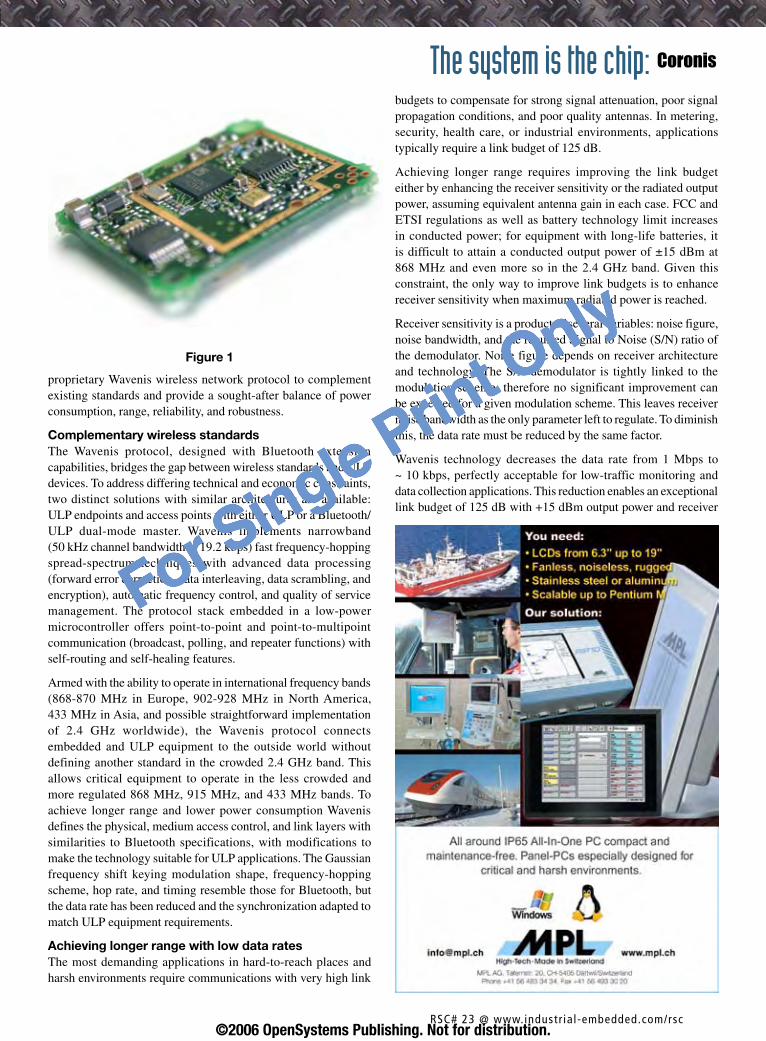
proprietary Wavenis wireless network protocol to complement existing standards and provide a sought-after balance of power consumption, range, reliability, and robustness.
Complementary wireless standards The Wavenis protocol, designed with Bluetooth extension capabilities, bridges the gap between wireless standards and ULP devices. To address differing technical and economic constraints, two distinct solutions with similar architectures are available: ULP endpoints and access points with either ULP or a Bluetooth/ULP dual-mode master. Wavenis implements narrowband (50 kHz channel bandwidth at 19.2 kbps) fast frequency-hopping spread-spectrum techniques with advanced data processing (forward error correction, data interleaving, data scrambling, and encryption), automatic frequency control, and quality of service management. The protocol stack embedded in a low-power microcontroller offers point-to-point and point-to-multipoint communication (broadcast, polling, and repeater functions) with self-routing and self-healing features.
Armed with the ability to operate in international frequency bands (868-870 MHz in Europe, 902-928 MHz in North America, 433 MHz in Asia, and possible straightforward implementation of 2.4 GHz worldwide), the Wavenis protocol connects embedded and ULP equipment to the outside world without defining another standard in the crowded 2.4 GHz band. This allows critical equipment to operate in the less crowded and more regulated 868 MHz, 915 MHz, and 433 MHz bands. To achieve longer range and lower power consumption Wavenis defines the physical, medium access control, and link layers with similarities to Bluetooth specifications, with modifications to make the technology suitable for ULP applications. The Gaussian frequency shift keying modulation shape, frequency-hopping scheme, hop rate, and timing resemble those for Bluetooth, but the data rate has been reduced and the synchronization adapted to match ULP equipment requirements.
Achieving longer range with low data ratesThe most demanding applications in hard-to-reach places and harsh environments require communications with very high link
budgets to compensate for strong signal attenuation, poor signal propagation conditions, and poor quality antennas. In metering, security, health care, or industrial environments, applications typically require a link budget of 125 dB.
Achieving longer range requires improving the link budget either by enhancing the receiver sensitivity or the radiated output power, assuming equivalent antenna gain in each case. FCC and ETSI regulations as well as battery technology limit increases in conducted power; for equipment with long-life batteries, it is difficult to attain a conducted output power of ±15 dBm at 868 MHz and even more so in the 2.4 GHz band. Given this constraint, the only way to improve link budgets is to enhance receiver sensitivity when maximum radiated power is reached.
Receiver sensitivity is a product of several variables: noise figure, noise bandwidth, and the required Signal to Noise (S/N) ratio of the demodulator. Noise figure depends on receiver architecture and technology. The S/N demodulator is tightly linked to the modulation scheme; therefore no significant improvement can be expected for a given modulation scheme. This leaves receiver noise bandwidth as the only parameter left to regulate. To diminish this, the data rate must be reduced by the same factor.
Wavenis technology decreases the data rate from 1 Mbps to ~ 10 kbps, perfectly acceptable for low-traffic monitoring and data collection applications. This reduction enables an exceptional link budget of 125 dB with +15 dBm output power and receiver
Figure 1
The system is the chip: Coronis
RSC# �� @ www.industr ial-embedded.com/rsc©2006 OpenSystems Publishing. Not for distribution.
For Single Print Only

sensitivity of -110 dBm, which is 20 dB better than state-of-the-art Bluetooth devices and 15 dB better than ZigBee RF receivers. Channel bandwidths of 50 kHz and only -3 dBi gain helical antennas enable ranges up to 1 km line-of-sight or typically 200 m indoors.
Fast connectivity with ultra-low-power consumptionDevice synchronization poses a tremendous challenge to providing battery-powered wireless devices with a long life span. For a sensor network to remain operational for several years, synchronization cannot be maintained continuously. When synchronization is lost in a synchronized network, devices try to reestablish synchronization by entering into high power consumption mode, thereby shortening life span. One solution is for devices to synchronize only when necessary, backing down communication between devices immediately afterward. Synchronization can be performed at predetermined times depending on the application (1 second latency for telemetry or metering, or as low as 10 ms for lighting).
Because devices toggle between receive mode and standby mode for most of their lives, Wavenis has combined relaxed network synchronization (that is, not forcing modules to stay on and synchronized for extended periods of time) with an efficient sleep/wake-up mode to offer battery-powered nodes with many years of operating lifetime. A routing algorithm automatically configures and manages nodes to avoid exponential increases in communications when setting up network nodes, facilitating extended range via reduced bandwidth. For example, Wavenis
offers 1 second access time with 10 μA average operating current (at 2.7 V). It is also optimized for applications in which small amounts of data are transmitted regularly but not constantly, with data rates ranging from 4.8 kbps to 100 kbps and a typical throughput of 19.2 kbps.
Developing an ultra-low-power SoCWavenis is currently implemented in a two-chip solution: an RF transceiver plus a microcontroller for the stack and applications. To continue offering the best technical performance at the most competitive price, Coronis is developing a Wavenis SoC with all the necessary electronic circuitry and system components on a single IC. The new SoC will incorporate an enhanced wireless transceiver with a unique ultra-low-power microcontroller architecture, reducing power consumption by 30 percent. Designed in 0.18 μm RF CMOS, the SoC will contain the embedded Wavenis communication protocol stack and dedicated memory for application stack. Development tools including a dedicated C compiler will also be included, enabling developers to create new applications easily and in a familiar environment. Delivery is expected early 2007.
Integrators and OEMs around the world have deployed more than 800,000 Wavenis-based products as of press time. The Wavenis Open Source Alliance supports ongoing standardization efforts and facilitates cooperation among technology providers, integrators, and service providers. This deployed base and the continued development of Wavenis technology offers industrial designers a proven wireless networking solution. IES
Christophe Dugas is director of marketing and communications for Coronis Systems, dealing with strategic partnerships and alliances with major industrial companies for Wavenis technology since 2001. In previous roles, he worked at Nokia as a strategic marketing manager for application-specific RF ICs,
STMicroelectronics as the technical marketing manager for the RF product lines, and Europe Telecom where he developed microwave sensors for autonomous robotics. He graduated from Polytech Montpellier France in 1990 with a Microelectronics Engineering degree.
To learn more, contact Christophe at:
Coronis Systems, S.A.Le Millénaire290 rue Alfred Nobel34000 MontpellierFrance Tel: +33-467-22-66-70E-mail: [email protected] Website: www.coronis.com
Go www.wavenis-osa.orgGo www.wavenis-osa.org
The system is the chip: Coronis
RSC# �4 @ www.industr ial-embedded.com/rsc©2006 OpenSystems Publishing. Not for distribution.
For Single Print Only
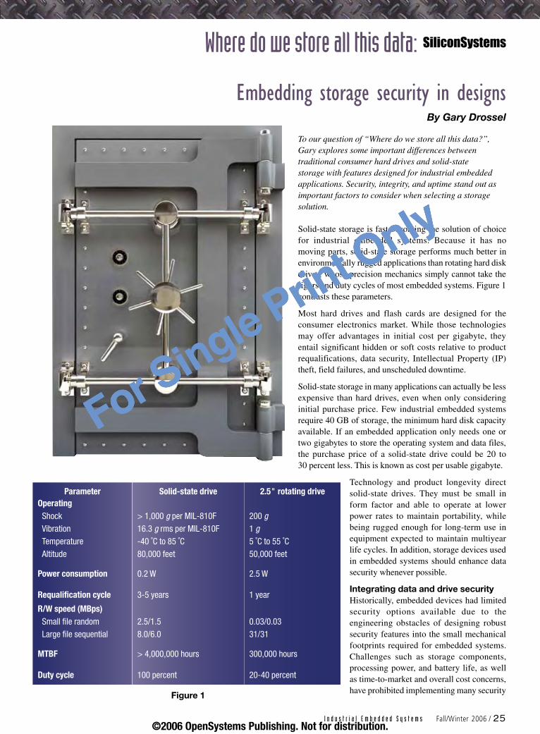
To our question of “Where do we store all this data?”, Gary explores some important differences between traditional consumer hard drives and solid-state storage with features designed for industrial embedded applications. Security, integrity, and uptime stand out as important factors to consider when selecting a storage solution.
Solid-state storage is fast becoming the solution of choice for industrial embedded systems. Because it has no moving parts, solid-state storage performs much better in environmentally rugged applications than rotating hard disk drives, whose precision mechanics simply cannot take the rigors and duty cycles of most embedded systems. Figure 1 contrasts these parameters.
Most hard drives and flash cards are designed for the consumer electronics market. While those technologies may offer advantages in initial cost per gigabyte, they entail significant hidden or soft costs relative to product requalifications, data security, Intellectual Property (IP) theft, field failures, and unscheduled downtime.
Solid-state storage in many applications can actually be less expensive than hard drives, even when only considering initial purchase price. Few industrial embedded systems require 40 GB of storage, the minimum hard disk capacity available. If an embedded application only needs one or two gigabytes to store the operating system and data files, the purchase price of a solid-state drive could be 20 to 30 percent less. This is known as cost per usable gigabyte.
Technology and product longevity direct solid-state drives. They must be small in form factor and able to operate at lower power rates to maintain portability, while being rugged enough for long-term use in equipment expected to maintain multiyear life cycles. In addition, storage devices used in embedded systems should enhance data security whenever possible.
Integrating data and drive securityHistorically, embedded devices had limited security options available due to the engineering obstacles of designing robust security features into the small mechanical footprints required for embedded systems. Challenges such as storage components, processing power, and battery life, as well as time-to-market and overall cost concerns, have prohibited implementing many security
EmbeddingstoragesecurityindesignsBy Gary Drossel
Where do we store all this data: SiliconSystems
Parameter Solid-state drive 2.5" rotating driveOperatingShock > 1,000 g per MIL-810F 200 gVibration 16.3 g rms per MIL-810F 1 gTemperature -40 ˚C to 85 ˚C 5 ˚C to 55 ˚CAltitude 80,000 feet 50,000 feet
Power consumption 0.2 W 2.5 W
Requalification cycle 3-5 years 1 year
R/W speed (MBps)Small file random 2.5/1.5 0.03/0.03Large file sequential 8.0/6.0 31/31
MTBF > 4,000,000 hours 300,000 hours
Duty cycle 100 percent 20-40 percent
Figure 1
I n d u s t r i a l E m b e d d e d S y s t e m s Fall/Winter 2006 / 25©2006 OpenSystems Publishing. Not for distribution.
For Single Print Only

features in hard drives and traditional flash cards.
The security industry has focused on portable storage devices for the consumer electronics industry, such as USB thumb drives, operating under the basic premise that users want the security algorithm to travel with the device. This allows the user to protect and use the data on any system, including an office PC, home computer, Internet kiosk, or other public computer. Software applications and user data are encrypted and password protected using industry-defined security protocols.
Companies that use industrial embedded systems must operate under a different premise. Data must be rendered unreadable if the storage devices are removed from the systems for which they were intended. OEMs want to make sure their proprietary software IP, and perhaps their customers’ data, are not available to unauthorized users.
In the industrial embedded systems market, the host system must maintain ultimate control over security algorithms to protect data and prevent IP theft. These algorithms can be as simple as ensuring the correct storage product is in the host, or as intricate as tying the software IP and
application data directly to the storage device. These algorithms are proprietary to the host system designer, and are therefore inherently more secure than well-known industry-standard implementations.
Key functions secure dataIn general, OEMs need to implement two key functions in their applications. First, they must ensure the end customer is using a qualified storage device in the system. Often for warranty or service purposes, the OEM must know the specific drive originally shipped with the equipment is indeed still in the system.
Secondly, OEMs need a low-level command that ties application data and software IP to a specific drive so the host system can verify the drive and create its own unique encryption keys to prevent theft. With such a command, any application that ties storage to the host system, such as companies that routinely ship software IP upgrades, can select the right level of advanced security to prevent intellectual property theft.
Through a low-level command, the host can read one or more unique pieces of specific data that can be used for validation. The host system can then use that data to create encryption/decryption keys for software IP and application data. While this method
does not provide copy protection, it does inhibit the use of the particular software on any system other than the original host. It is important to note that the data in question should be stored in a secure area on the solid-state drive.
In the security zoneIn addition to IP theft prevention, industrial embedded system OEMs must consider security requirements not only for the solid-state drive itself, but also for different data types. Advanced storage technology allows engineers to define multiple independent security zones with different security parameters for ultimate protection and flexibility. This is especially important in applications such as wearable computers or industrial PCs, where application program information, sensitive documents, and classified data can be stored independently with unique security parameters.
Most off-the-shelf operating systems such as Windows and Linux require registry and similar files to be updated continuously. Therefore, it is impossible to store these operating systems on the same physical drive as the files that need protection without using advanced zoning technology. When properly implemented, zoning technology can reduce overall system cost by reducing the number
Advanced zoning technologyAn industrial automation OEM manufactures in-line food processing equipment. The machine has three different storage requirements:
Store and manage specific validation codes required by regulatory agencies
Store the application-specific program files
Run a Windows-based operating system and log events and errors
Previously, the OEM needed three separate storage products to accomplish this task: a secure EPROM for code validation, a CD-ROM for read-only access to the program files, and a hard drive for the operating system and logging function. All three requirements can now be satisfied by one solid-state drive with advanced zoning technology. One zone implements full password protection to provide restricted access to the validation codes, the second provides read-only access to the program files, and the third allows full read-and-write access.
1.
2.
3.
Tying storage to the host systemAn industrial controls OEM sells software upgrades to enhance the system’s human machine interface or provide some type of system-level improvement. The upgrade is shipped on a solid-state drive as a kit. The OEM wants to ensure the software is tied only to that specific drive so that it does not work properly in the host system even if it is copied onto another device. In this case, benefits to the OEM include IP theft prevention, new market opportunities, capturing untapped revenue streams, and enhanced product differentiation.
Where do we store all this data: SiliconSystems
2� / Fall/Winter 2006 I n d u s t r i a l E m b e d d e d S y s t e m s©2006 OpenSystems Publishing. Not for distribution.
For Single Print Only
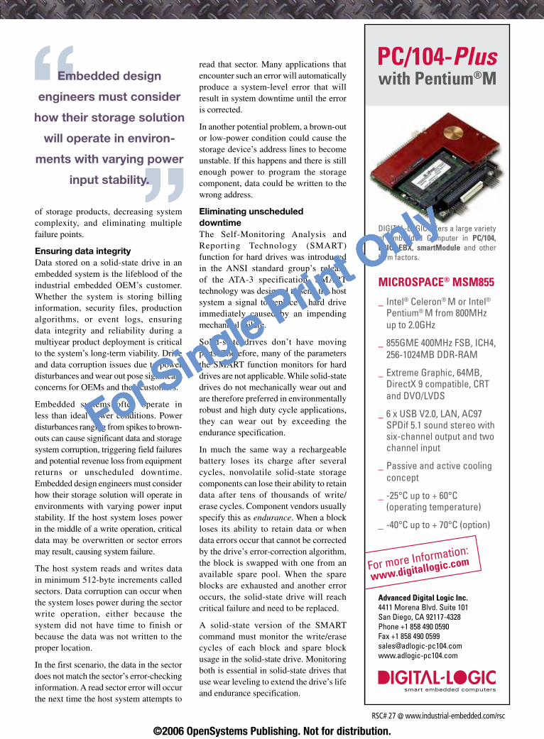
of storage products, decreasing system complexity, and eliminating multiple failure points.
Ensuring data integrityData stored on a solid-state drive in an embedded system is the lifeblood of the industrial embedded OEM’s customer. Whether the system is storing billing information, security files, production algorithms, or event logs, ensuring data integrity and reliability during a multiyear product deployment is critical to the system’s long-term viability. Drive and data corruption issues due to power disturbances and wear out pose significant concerns for OEMs and their customers.
Embedded systems often operate in less than ideal power conditions. Power disturbances ranging from spikes to brown-outs can cause significant data and storage system corruption, triggering field failures and potential revenue loss from equipment returns or unscheduled downtime. Embedded design engineers must consider how their storage solution will operate in environments with varying power input stability. If the host system loses power in the middle of a write operation, critical data may be overwritten or sector errors may result, causing system failure.
The host system reads and writes data in minimum 512-byte increments called sectors. Data corruption can occur when the system loses power during the sector write operation, either because the system did not have time to finish or because the data was not written to the proper location.
In the first scenario, the data in the sector does not match the sector’s error-checking information. A read sector error will occur the next time the host system attempts to
read that sector. Many applications that encounter such an error will automatically produce a system-level error that will result in system downtime until the error is corrected.
In another potential problem, a brown-out or low-power condition could cause the storage device’s address lines to become unstable. If this happens and there is still enough power to program the storage component, data could be written to the wrong address.
Eliminating unscheduled downtime The Self-Monitoring Analysis and Reporting Technology (SMART) function for hard drives was introduced in the ANSI standard group’s release of the ATA-3 specification. SMART technology was designed to send the host system a signal to replace a hard drive immediately caused by an impending mechanical failure.
Solid-state drives don’t have moving parts. Therefore, many of the parameters the SMART function monitors for hard drives are not applicable. While solid-state drives do not mechanically wear out and are therefore preferred in environmentally robust and high duty cycle applications, they can wear out by exceeding the endurance specification.
In much the same way a rechargeable battery loses its charge after several cycles, nonvolatile solid-state storage components can lose their ability to retain data after tens of thousands of write/erase cycles. Component vendors usually specify this as endurance. When a block loses its ability to retain data or when data errors occur that cannot be corrected by the drive’s error-correction algorithm, the block is swapped with one from an available spare pool. When the spare blocks are exhausted and another error occurs, the solid-state drive will reach critical failure and need to be replaced.
A solid-state version of the SMART command must monitor the write/erase cycles of each block and spare block usage in the solid-state drive. Monitoring both is essential in solid-state drives that use wear leveling to extend the drive’s life and endurance specification.
Embedded design
engineers must consider
how their storage solution
will operate in environ-
ments with varying power
input stability.
PC/104-Pluswith Pentium®M
MICROSPACE® MSM855
_ Intel® Celeron® M or Intel®
Pentium® M from 800MHz up to 2.0GHz
_ 855GME 400MHz FSB, ICH4, 256-1024MB DDR-RAM
_ Extreme Graphic, 64MB, DirectX 9 compatible, CRT and DVO/LVDS
_ 6 x USB V2.0, LAN, AC97 SPDif 5.1 sound stereo with six-channel output and two channel input
_ Passive and active cooling concept
_-25°C up to + 60°C (operating temperature)
_-40°C up to + 70°C (option)
Advanced Digital Logic Inc.4411 Morena Blvd. Suite 101San Diego, CA 92117-4328Phone +1 858 490 0590Fax +1 858 490 [email protected]
For more Information:
www.digitallogic.com
DIGITAL-LOGIC offers a large varietyof Embedded Computer in PC/104,EPIC, EBX, smartModule and otherform factors.
RSC# �7 @ www.industrial-embedded.com/rsc
©2006 OpenSystems Publishing. Not for distribution.
For Single Print Only

Most system designers require a feedback methodology that yields meaningful data any time during system operation. Technologies such as SiliconSystems’ patent-pending SiSMART technology act as an early warning system for the host and provide status on the percentage of drive usage relative to the endurance specification. The host can then set its threshold and can schedule preventative maintenance before the system goes down unexpectedly.
Choosing the right solid-state technologyNot all solid-state storage products are created equal. Though they may look the same, industrial solid-state drives in a 2.5" or CompactFlash form factor differ greatly from solid-state drives or CompactFlash cards designed for the consumer electronics market. Figure 2 outlines the inherent technology differences.
The term standard CompactFlash card can be a bit misleading. Flash cards must pass the test suite defined by the CompactFlash Association. These tests allow for a relatively wide range in some timing parameters, which can vary with both hardware and firmware changes. Most consumer-oriented products have enough other system overhead to render these changes insignificant.
Embedded systems, on the other hand, usually have strict timing requirements. Even the slightest changes can cause significant issues. Therefore, strict
adherence to consistent product per-formance and specification is much more necessary in embedded systems. This need is not well served by consumer-based products that provide no change notification and may vary from lot to lot.
The most industry-recognized differenti-ator between solid-state storage and commercial flash cards is write/erase cycle endurance. Solid-state drives have superior error-correction capabilities and wear-leveling algorithms that can significantly extend the life of standard storage components. The previously described power issues are significantly less well known but much more prevalent in embedded applications. Power-related corruption causes approximately 75 percent of field failures. In these instances, the drive is not physically damaged or worn out, but the data is rendered unusable.
Traditional solid-state drives and flash cards do not incorporate any type of feedback mechanism and consequently are allowed to operate until they exceed the endurance specification and fail. While this may be acceptable for consumer electronics products that store music files or digital photographs, it is not appropriate for applications charged with storing critical business data. Industrial embedded system designers will benefit greatly from being able to poll the storage device to receive usage and diagnostics information that helps make the host system more intelligent.
Solid-state replaces more and moreSolid-state storage will continue to replace rotating hard disk drives in embedded systems as the cost per usable gigabyte required by the application continues its rapid decline. Industrial embedded system applications require high performance, high reliability, and multiyear product life cycles to minimize the total cost of storage ownership over the entire product deployment. Enhanced security features are also required as more and more embedded devices are being shared or deployed over networks. The risk of losing productivity due to unscheduled downtime from data corruption or field failures is an even greater concern; thus, managing and protecting data in these applications is critical.
Solid-state drives specifically designed for the industrial embedded systems market can offer OEMs the ability to create significant product differentiation and enhance the deployment of their systems by eliminating the endurance, data integrity, reliability, and security concerns associated with consumer-oriented hard drives and flash cards. IES
Gary Drossel joined SiliconSystems in 2004 and is vice president of product planning, responsible for product marketing, product planning, strategic
marketing, and the application engineering departments. A 15-year embedded computing industry veteran with a wealth of knowledge concerning solid-state storage technology, he has also played a leading role in developing the company’s marketing strategy, including product roll-out and customer introduction. Gary received a BS in Electrical and Computer Engineering from the University of Wisconsin.
To learn more, contact Gary at:
SiliconSystems, Inc. 26940 Aliso Viejo ParkwayAliso Viejo, CA 92656Tel: 949-900-9414E-mail: [email protected]: www.siliconsystems.com
Parameter SiliconDrive CF CompactFlash card
Write/Erase endurance > 2M cycles per block < 100K cycles per card
Error Correction (ECC) 6 bit 1-2 bit
Wear-leveling algorithm Over the entire SiliconDrive Over free space only
Power-down protection Yes No
R/W speed (MBps)Single sector 1-2 MBps 30-40 kBpsLarge file 6-8 MBps 3-5 MBps
Requalification cycle 3-5 years 1 year
Maximum capacity 8 GB 4 GB
Figure 2
Where do we store all this data: SiliconSystems
28 / Fall/Winter 2006 I n d u s t r i a l E m b e d d e d S y s t e m s©2006 OpenSystems Publishing. Not for distribution.
For Single Print Only

EmbeddingWindowsXP:AdeeperlookBy Patric Dove
Windows XP Embedded creates options for industrial designers that the standard version of
Windows XP doesn’t offer. Patric explores the flexibility and benefits the embedded version of
the popular Operating System (OS) provides.
The embedded version of Windows XP is a componentized version of the well-known Windows XP Professional OS. Instead of wrapping everything tightly into one single package, XP Embedded breaks the OS down into more than 10,000 individual components, allowing developers to create systems with the functionality and familiar features of XP. One of the most attractive features of XP Embedded is that it is much smaller than XP for desktop systems, so small that it can fit on a 512 MB CompactFlash card with room left for system applications and data backup. The CompactFlash card resists vibration and shock for reliable storage and can be replaced easily for fast system upgrades.
XP Embedded’s choices of boot methods, wide range of communications options, and array of system configuration tools also may interest embedded system developers. XP Embedded uses the same application programming environment as XP, which makes application development quick and easy, and allows the same application to run on desktop and embedded machines. And it has improved code protection for critical kernel structures, file protection, and more.
Suggested industrial applications for XP Embedded include human machine interface panels, process automation systems, industrial robots, inspection systems, soft programmable logic controllers, remote control devices, and factory monitoring systems. A few of the many possible XP Embedded consumer and commercial applications include set-top boxes and terminals such as kiosks and ATMs.
Boot optionsEmbedded XP supports a variety of boot methods. Remote boot service allows the system to automatically download the system image and boot from a network, which is useful for diskless systems and systems that need frequent updates. It also makes it possible to deploy systems with no persistent storage at all, either hard drive or flash RAM.
The Enhanced Write Filter (EWF) feature allows the system to boot from a write-protected hard drive, flash, or other read-only media, or to use a protected area on a disk. Instead of writing to the boot drive, which, as in the case of flash, may have a limited number of write cycles, the system will write to a local cache. Protecting a volume from write access eliminates the threat of viruses, and running from RAM removes corrupt files if the machine is shut down during an operation. EWF has password protection and can be turned on and off when installing new software.
EWF redirects all write operations to another storage location called an overlay, which can be in RAM or on another disk partition. In addition, an EWF volume is created on the media in unpartitioned disk space to store configuration information about all EWF-protected volumes on the device, including the number and sizes of protected volumes and overlay levels.
XP Embedded allows configuration of a runtime image to boot from a hibernation file with EWF enabled. This enables quicker boot time, facilitates defining the state of a system by booting with specific applications and services running, and supports the hibernate once, resume many utility. This utility allows the user to define a hibernated state that quickly wakes up the system without having to perform a full OS boot, which is useful for systems that spend much of their time in standby mode.
As another aid to the boot process, Advantech offers the Advantech WatchDog API, which works with a watchdog timer, a device or electronic card that performs a specific operation after
Computing: Advantech
I n d u s t r i a l E m b e d d e d S y s t e m s Fall/Winter 2006 / 29©2006 OpenSystems Publishing. Not for distribution.
For Single Print Only
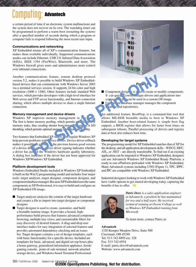
a certain period of time if an electronic system malfunctions and the system does not recover on its own. The watchdog timer can be programmed to perform a warm boot (restarting the system) after a specified number of seconds during which a program or computer fails to respond following the most recent user input.
Communications and networkingXP Embedded retains all of XP’s communication features, but makes them available individually. Supported communications modes can include Ethernet, USB 2.0, Infrared Data Association (IrDA), IEEE 1394 (FireWire), Bluetooth, and more. The Windows firewall gives users and administrators more control over inbound connections.
Another communications feature, remote desktop protocol version 5.2, makes it possible to build Windows XP Embedded-based devices that can communicate with Windows Server 2003 via a terminal services session. It supports 24-bit color and high resolution (1600 x 1200). Other features include standard Web services, which provides developers with a high-level interface for Web server and FTP server functionality, and Internet connection sharing, which allows multiple devices to share a single Internet connection.
Memory management and device driversWindows XP improves memory management in two ways. The first is better memory pooling, which permits prioritization of memory tasks, thus creating shorter boot times. The second is I/O throttling, which permits optimal memory allocation and stability.
Two features that Embedded XP shares with regular Windows XP help prevent problems with device drivers. Device driver rollback makes it possible to go back to the previous known good version of a device driver, while device driver signing indicates whether a driver has passed the Windows hardware quality laboratory. A dialog box indicates if the driver has not been approved for Windows XP/Windows XP Embedded.
Platform development toolsWindows Embedded Studio included in Windows XP Embedded is built on the Win32 programming model and includes four major tools: target analyzer, target designer, component designer, and component database manager. Because XP Embedded uses the same components as XP Professional, it is easy to build and configure an XP Embedded OS image.
Target analyzer analyzes the content of the target hardware and creates a file to import into target designer or component designer.Target designer is used to create, customize, and build a bootable runtime image. It provides a hosted, high-performance build process that features advanced component browsing, multiple tree views, and customizable filters for easy discovery of desired features. A drag-and-drop user interface makes for easy integration of selected features and provides automated dependency checking and an issues list. Target designer contains a set of design templates, each with basic functionality for a specific device. Included are templates for basic, advanced, and digital set-top boxes plus a home gateway, generalized information appliance, kiosk/gaming console, point-of-sale terminal, network attached storage device, and Windows-based Terminal Professional.
n
n
Component designer is used to create or modify components. It can quickly convert unique drivers and applications into components that can be used in a custom OS image.Component database manager manages the component database and repositories.
An additional feature, BootPrep, is a command-line tool that allows MS-DOS bootable media to boot to Windows XP Embedded. Another boot-related feature is simple boot flag support, a BIOS register that allows for faster boot times on subsequent reboots. Parallel processing of drivers and registry data at boot also reduces boot time.
Developing for target systemsThe programming model for XP Embedded matches that of XP for the desktop, and all application development skills – WIN32, MFC, ATL, or .NET – are directly transferable. To find out if an existing application can be migrated to Windows XP Embedded, designers can use Advantech Windows XP Embedded Ready Platform, a ready-to-run ePlatform preloaded with Windows XP Embedded. Many Advantech systems including UNO (Figure 1), TPC, IPPC, and IPC are compatible with Windows XP Embedded.
Industrial designers looking to work with Windows XP Embedded have viable options to get started developing today, capturing the benefits it has to offer. IES
Patric Dove is a sales application engineer at Advantech, a position he has maintained for two and a half years. He received technical training at Owens College as well as Windows XP Embedded training from Microsoft.
To learn more, contact Patric at:
Advantech1320 Kemper Meadow Drive, Suite 500Cincinnati, OH 45240Tel: 513-742-8895 ext. 328Fax: 513-742-0554E-mail: [email protected]: www.advantech.com
n
n
Figure 1
Computing: Advantech
30 / Fall/Winter 2006 I n d u s t r i a l E m b e d d e d S y s t e m s©2006 OpenSystems Publishing. Not for distribution.
For Single Print Only
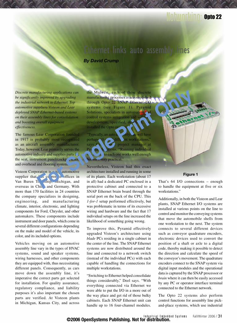
Discrete manufacturing applications can be significantly improved by upgrading the industrial network to Ethernet. Top automotive suppliers Visteon and Lear deployed SNAP Ethernet-based systems on their assembly lines for consolidation and boosting overall equipment effectiveness.
The famous Lear Corporation founded in 1917 is probably most recognized as an aircraft assembly manufacturer. Today, however, Lear primarily serves the automotive industry and supplies parts for the seat, instrument panel/cockpit, door, and overhead and flooring systems.
Visteon Corporation is a top automotive supplier that has corporate offices in Van Buren Township, Michigan, and overseas in China and Germany. With more than 170 facilities in 24 countries the company specializes in designing, engineering, and manufacturing climate, interior, electronic, and lighting components for Ford, Chrysler, and other automakers. These components include instrument and door panels, which come in several different configurations depending on the make and model of the vehicle, its color, and its included options.
Vehicles moving on an automotive assembly line vary in the types of HVAC systems, sound and speaker systems, wiring harnesses, and other components they are equipped with, thus necessitating different panels. Consequently, as cars move down the assembly line, it’s imperative the correct parts get selected for installation. For quality assurance, regulatory compliance, and liability purposes it’s also important the chosen parts are verified. At Visteon plants in Michigan, Kansas City, and across
the Midwest, each of these discrete manufacturing processes is accomplished through Opto 22 SNAP Ethernet I/O systems (see Figure 1). Pyramid Solutions, specialists in automation and control systems integration and software development, specified, designed, and installed the Opto systems.
“Typically, an auto assembly line will have perhaps 10 or 20 different workstations,” says Greg Deel, project manager at Pyramid Solutions. “Running individual serial lines to each one works well enough but isn’t very practical.”
Nevertheless, Visteon had this exact architecture installed and running in some of its plants. Each workstation (about 17 in all) had a dedicated PC enclosed in a protective cabinet and connected to a SNAP Ethernet brain board through the serial port on the back of the CPU. This 1-for-1 setup performed effectively, but was problematic in terms of its excessive wiring and hardware and the fact that 17 individual setups on the line increased the likelihood of something going wrong.
To improve this, Pyramid effectively upgraded Visteon’s architecture using blade PCs residing in a single cabinet in the center of the line. The SNAP Ethernet systems are now distributed around the line and connected to a network switch (instead of the individual PCs) with each capable of handling the connections for multiple workstations.
“Switching to Ethernet helped consolidate things considerably,” Deel says. “With everything connected via Ethernet we were able to put the I/O in a more out of the way place and get rid of those bulky cabinets. Each SNAP Ethernet unit can handle up to 16 four-channel modules.
That’s 64 I/O connections – enough to handle the equipment at five or six workstations.”
Additionally, in both the Visteon and Lear plants, SNAP Ethernet I/O systems are installed at various points on the line to control and monitor the conveying systems that move the automobile shells from one workstation to the next. The system connects to several different devices such as conveyor quadrature encoders, electronic devices used to convert the position of a shaft or axle to a digital code, thereby making it possible to detect the direction and calculate the speed of the conveyor’s movement. The quadrature encoders connect to the SNAP system via digital input modules and the operational data is captured by the SNAP processor or brain where it can then be easily accessed by any PC or operator interface terminal connected to the Ethernet network.
The Opto 22 systems also perform control functions for assembly line pick-and-place systems, which use industrial
EthernetlinksautoassemblylinesBy David Crump
Networking: Opto 22
Figure 1
I n d u s t r i a l E m b e d d e d S y s t e m s Fall/Winter 2006 / 31©2006 OpenSystems Publishing. Not for distribution.
For Single Print Only
robotics to sequentially choose and assemble appropriate auto parts from a diverse selection. Specifically, the SNAP Ethernet unit uses digital output modules to turn on lights that identify correct parts for the system’s picker.
“The SNAP Ethernet system also plays a key role in our parts verification and quality control,” says Jason Linton, operations manager at Lear, which manufactures systems for the Ford F-150, Plymouth Neon, and Dodge Durango, among others. “The system has been configured to control Andon call boxes used by assembly line operators to activate alerts when critical or emergency conditions occur.”
Such conditions could require stopping the assembly line altogether, but usually call boxes are used to notify specific plant floor personnel such as the production manager or quality assurance supervisor that a certain matter requires their immediate attention. As visual indication from the bulb or LED on the call box can sometimes go unnoticed, the SNAP Ethernet system provides an interface from the call boxes to additional lights, horns, and marquees throughout the plant. For example, operators manually activate the call box at their workstation if they are running low on parts. The call box then sends a signal to the SNAP system, which, in turn, activates a siren intended to alert the materials manager.
The Opto product has accomplished this work unobtrusively. Pyramid deployed the SNAP Ethernet systems at the Visteon and Lear facilities without replacing, modifying, or otherwise disturbing the existing installed control systems – something Deel considers extremely important to customers at all levels of the organization, from manufacturing managers on the plant floor all the way up to the COO.
“As an integrator, it’s important for Pyramid to offer systems and solutions that don’t always call for a rip-and-replace approach,” Deel says.
Deel claims that prospective customers are understandably reluctant to retire
automation and control hardware that’s performing perfectly well when all they really want is some supplementary functionality such as a few added control functions at one or two workstations or quick data acquisition from one part of the manufacturing process.
“The Opto hardware is so open and versatile that we can easily integrate it into installed control systems and configure it to perform its function without disturbing I/O or field wiring and little or no software reprogramming,” Deel says.
As proof, both Visteon and Lear have their SNAP Ethernet systems working in control systems alongside Siemens and Allen-Bradley PLCs.
“The SNAP Ethernet system has proven beneficial for us, saving us a good deal of money and helping to boost the company’s overall equipment effectiveness rating to more than 95 percent,” Linton says. IES
David Crump joined Opto 22 in 2001, where as a marketing communications manager he is the company’s press contact
and public relations officer. He has authored numerous op-ed pieces and technology-related articles, and has been published in several magazines including Automation in Theory & Practice, Control Engineering, Design News, M2M, Machine Design, and Manufacturing IT. David earned his BA in Communications from Seton Hall University.
To learn more, contact David at:
Opto 2243044 Business Park Drive Temecula, CA 92590Tel: 951-695-3010 E-mail: [email protected]: www.opto22.com
The SNAP Ethernet unit uses
digital output modules to turn
on lights that identify correct
parts for the system’s picker.PC/104 Multitech Socket Module Carrier Board
Two serial ports (RS-232/RS-422) Connects either serial port to ethier
Universal Socket in Standalone mode Allows bridging of the modules
PC/104 interface to high speed quad UART
FLEXCOM104
100Mhz PC/104 Module
168 Watt High Efficiency Power Supply
Total Power: 168 Watt with ATX Interface+3.3V, +5V, 12V output
6V to 40V DC input rangeExtended temperature: -40OC to +85OCRS232 serial port / Optocoupled inputs
HPS3512
1.800.665.5600www.tri-m.com [email protected]
tel: 604.945.9565 fax: 604.945.9566HEAD OFFICE: VANCOUVER
Featuring the new edition ZFx86 FailSafe® Embedded PC-on-a-Chip
Dual watchdog timers, PhoenixBIOS and FAILSAFE Boot ROM
Extended temperature -40°C to 85°C
MZ104
RSC# �� @ www.industrial-embedded.com/rsc
©2006 OpenSystems Publishing. Not for distribution.
For Single Print Only

Networking: Apprion
In a large enterprise, wireless networking can proliferate quickly and possibly end up causing as many problems as it solves. In this viewpoint, Ian points out some challenges and offers ideas to help large users manage wireless networks for the greater good.
Wireless labyrinthIn the petrochemical, health care, energy, and other industry sectors, manufacturers today are deploying a diverse range of new wireless technology solutions to enhance controls, processes, costs, and security in their factories. Examples include:
Process measurements taken from wireless temperature sensors with transmittersWireless video cameras for perimeter securityRadio Frequency Identification (RFID) technology for in-plant inventory or asset trackingSensors for monitoring equipment deterioration in real timeWireless networks enabling engineers and technicians to process in-field work immediately, rather than manually later on back at their desks
Wireless systems continue to disseminate throughout industrial environments, increasingly deployed in silos of functionality within the same manufacturing environment: process control systems, asset identification and location; perimeter surveillance; temperature; vibration and pressure monitoring; activation and automation of emergency response systems; and so on. However, this trend creates a whole new set of problems. How do designers sort out and manage the growing tangle of all these disparate wireless solutions operating with different frequencies,
n
n
n
n
n
conflicting standards, and protocols for different applications?
ZigBee, Wi-Fi, WiMAX, RFID, VoIP, Bluetooth, mesh networks – each is leveraged for specific applications. The bramble can be daunting, especially for industrial manufacturing where ad hoc applications are deployed without the expertise of dedicated staff assigned to look at the big picture. As illustrated by Figure 1, one size does not fit all in the wireless landscape.
Some of the emerging challenges accompanying the growth of wireless systems among manufacturers include limited spectrum allocations for certain radio frequencies; confusion about what standards to follow; interfering and conflicting frequencies; and different wireless protocols, processes, and gateways linking wireless and wired software communication systems.
The consequences of these challenges are especially acute when one department
implements a wireless system from a particular vendor and another department does the same using a different vendor. While this evolves in various departments and company locations, a host of issues may arise, such as security vulnerabilities, increased gateway link interference, transmission interruption, availability problems, data loss, and performance degradation. Furthermore, time-sensitive data may fail to be delivered when different wireless systems are competing for the same finite spectrum.
To achieve the full value of multiple wireless systems, manufacturers today need an overarching, enterprise-wide framework to manage and optimize their multiple wireless systems. Rather than ad hoc implementations and point solutions, manufacturers must take a big picture approach that analyzes best of breed wireless applications and tie them together on a common software platform that’s aligned with overall business objectives.
ManagingwirelessacrosstheindustrialenterpriseBy Ian McPherson
Figure 1
eps Mbps p
i AX
i- i
I n d u s t r i a l E m b e d d e d S y s t e m s Fall/Winter 2006 / 33©2006 OpenSystems Publishing. Not for distribution.
For Single Print Only

The same general principles of wired network systems management also apply to wireless networks, but new and unique challenges arise because the radio spectrum is finite and most wireless devices operate in unlicensed frequencies. As with wired networks, it is now essential to apply enterprise-level management practices to operate wireless networks.
To maximize productivity, security, and efficiency while reducing costs, managers and designers of wireless networks in industrial enterprises must address the following elements to be successful:
Manage and scale system architecturePrioritize business value at the enterprise levelIntegrate security measures and policies system wide
Manage and scale system architectureOptimum execution of any enterprise-wide policy requires a communications architecture that can accommodate the best categorical network technologies and vendors, emerging standards, and best wireless integration practices. The architecture must be based on a well-developed security model that includes functions such as authentication and role-based access control.
Network support and administration departments should treat wireless systems the same as any another network by focusing on managing enterprise-wide communications, not the individual technology. Because a single wireless protocol and frequency will never exist, the appropriate technology must be matched with the right application. Thus, the best approach for system-wide growth involves an integrated yet flexible management strategy that can deliver immediate benefits and be future proofed to adapt to business changes and technology developments.
Few companies can maintain the staff necessary to manage a complete wireless infrastructure, especially because demand for specialists with relevant skills is very high and supply is limited. As a result, outsourcing to a wireless specialist firm appears to be the most cost-effective strategy to maximize benefits and minimize risks at this time.
n
n
n
Prioritize business value at the enterprise levelLike wired networks, wireless networks link and deliver data between different points. The potential for far more granular data and detailed measurements in areas such as process variables exists with wireless due to the advantage of being implemented more rapidly without the cost of running wires between multiple points. Consequently, setting up measures for virtually any point or process of the enterprise and receiving this information in real time is possible.
Each department undoubtedly can make a strong case for deploying wireless networks within its internal operations, but issues of scalability, security, and investment protection make it imperative that these decisions be coordinated at the enterprise level, where priorities such as process controls, security, or logistics needs can best be evaluated and executed.
For example, a company competing in a mature marketplace with a strategy of being the low-cost provider might deploy wireless vibration sensors that tell when any asset is not operating optimally, and see savings on maintenance show up immediately in the bottom line. In contrast, a company competing on fast, reliable delivery might find the added cost of an RFID product tracking system would improve its competitive position.
Implement security measures and policies system wideSloppy networking practices, rather than intentional malicious interference, pose the greatest threats to wireless security. These can include seemingly innocuous practices such as not changing passwords according to policy, using obvious passwords such as initials, adding or deleting devices improperly, and any number of other lapses. Environmental or accidental RF noise, broken RF equipment, dynamic changes in the characterization of the RF site, and the range on noncompatible RF devices can also create interferences. Prevention of these kinds of problems must be engineered into the network from its inception and covered by an enterprise-aware security and performance management model.
For example, one network user might be taking wireless process measurements from a temperature transmitter while another user in the same plant might be running a wireless video camera for perimeter security. A third might be running an RFID inventory tracking application. Because they are in different departments and locations doing different things on different protocols, they might think they are isolated. In reality, those radio waves are comingling, creating tremendous potential for performance problems and mismanagement. This also highlights the issues that arise when trying to consolidate all applications around a single wireless technology rather than taking the systematic approach of creating a wireless infrastructure.
System-wide management policies must define all methods for using, sharing, and securing the available bandwidth. This carries implications for planning, implementation, operations, maintenance, and expansion. For these reasons, building an effective wireless infrastructure requires an open framework and engineered solution.
Policy management also ties into the end user’s existing IT requirements. One company might have IT policies in place that significantly differ from another in the exact same industry. The system must be designed to comply with particular corporate requirements for activities such as error condition reporting, network behavior observation, and optimization based on that information. It must cover every aspect of operation, from initial configuration to ongoing optimization.
Management platforms up to the challengeApprion and its strategic partner, Invensys, have found that manufacturers today need a wireless infrastructure management platform as well as a technology life-cycle program. This is necessary to develop a clear roadmap and put best practices in place for iterative management and expansion of wireless technology throughout a plant, facility, or department. This platform must first focus on business outcomes and objectives, while providing an immediate and cost-effective method for integrating the vast array of wireless-
Networking: Apprion
3� / Fall/Winter 2006 I n d u s t r i a l E m b e d d e d S y s t e m s©2006 OpenSystems Publishing. Not for distribution.
For Single Print Only

Networking: ZigBee
enabled products and devices increasingly coming to market.
Due to the great heterogeneity of wireless applications and the lack of a one size fits all technology solution, it is important to ensure that the necessary monitoring, management, and security capabilities span the entire wireless enterprise. At the same time, the platform should be flexible enough to allow disparate applications to share the spectrum within the context of their importance, time sensitivity, and mission criticality.
The Apprion solution to the management platform challenge provides an integrated offering including software and services that unify the security, policy, and network performance management of a heterogeneous wireless infrastructure through a single interface. This solution includes a unique application infrastructure called the Intelligent Operations Network (ION) pictured in Figure 2, designed for process manufacturing environments that need a secure, scalable, and affordable method to deploy a common wireless infrastructure across the facility and multiple operational areas.
These top-down, system-wide platform approaches fundamentally change the costs for manufacturers to improve plant-wide productivity, safety, and security as well as mitigate risks of unplanned downtime by automating process management,
modeling, and productivity applications with wireless technologies. The results provide a seamless wireless network that can be managed from a platform approach to meet the business objectives of the overall industrial enterprise. IES
Ian McPherson is vice president of marketing at Apprion and has more than 15 years of experience in research, development, and deployment of network
infrastructure and enterprise wireless technologies. Most recently, he was the founder and president of the Wireless Data Research Group, providing syndicated primary research and advisory services for emerging wireless technologies and machine to machine communications. Ian earned his BS in Business Administration from Cal Poly Pomona and his MA in Communications from Annenberg School for Communications, University of Southern California.
To learn more, contact Ian at:
Apprion, Inc.NASA AMES Research ParkBuilding 19, Suite 1000Moffett Field, CA 94035Tel: 650-934-5700 E-mail: [email protected] Website: www.apprion.com
Figure 2
DiskOnChip family of productsStandard Interfaces: including 32 pin DIP,
UBS and IDEMultiple capacities (16MB - 1GB)
Advanced Error Correction
Flash Solutions
4 serial ports Jumper selectable RS-232/422/485 on two ports
Dual 20-pin I/O headers (2 ports per header) Flexible address and interrupt selection
4x RS-232/RS-422/RS-485 Serial Port Module
1.800.665.5600www.tri-m.com [email protected]
tel: 604.945.9565 fax: 604.945.9566HEAD OFFICE: VANCOUVER
Multiple communication protocols supported: HDLC, SDLC, MonoSync, BiSync and Async
Two synchronous/asynchronous serial channelsData communications speeds up to 4.9 Mbps per channel
Support for both internal or external serial clocks
ComSync/104
Emerald MM
Two-channel, multi-protocol adapter for the PC/104
RSC# �� @ www.industrial-embedded.com/rsc
©2006 OpenSystems Publishing. Not for distribution.
For Single Print Only

The Final Word The Final Word The Final Word The Final Word The Final Word The Final Word The Final Word The Final Word The Final Word The Final Word The Final Word The Final Word The Final Word The Final Word The Final Word The Final Word The Final Word The Final Word The Final Word The Final Word The Final Word The Final Word The Final Word The Final Word The Final Word The Final Word The Final Word The Final Word The Final Word The Final Word The Final Word The Final Word THE FINAL WORd
By Jerry Gipper
Industrial equipment begs to be connected. From sensors gathering critical process data and control devices managing the processes all the way to business servers managed by the IT department, data must be collected and managed. To get the data from one end of the system to the other, connections must be made. Industrial computers have always been connected in one fashion or another for this reason. What is exciting about this now is the number of efficient choices that make connections happen.
Fifteen years ago we were in the thick of the fieldbus wars. At one time, more than 50 competing fieldbuses, both open standard and propr ie tary, v ied for implementation. Companies and trade associations lobbied their cause at every possible venue. Today that battle has settled down substantially to the point that only a handful of practical choices remain. It took many people years of efforts to reach this stage.
Wireless communications for industrial connectivity will experience the same challenge. Many competing wireless protocols are being deployed now, and it will take a while for these choices to go through the natural selection process.
Wireless technology has many benefits, including easy installation, few cables, portability, mobility, and wide coverage area. However, Radio Frequency (RF) has its own set of headaches, such as interference, noise, explosive environments, reliability, range, and performance. Many suppliers are using innovative technology to eliminate or reduce the headaches, but the solutions are fluid and dynamic at this stage. Thus, the solutions are coming quickly and in large quantities, many destined to be short-lived or specialized for selected uses and applications. This means
many options will be available in the foreseeable future, making a single solution impractical.
Wireless technology developers are a creative lot. They work hard to eke out more performance, pushing to get maximum bandwidth out of a challenging medium and fighting for spectrum to squeeze in more channels. They are developing error checking and correcting protocols that enable wireless communications to work in the noisy
RF environments often typical of industrial environments.
At the same time, power requirements constra in developers’ progress. They are not allowed to install high-power, point-to-point RF connections in most installations, so they must innovate ways to get the bandwidth today’s applications demand. Many of the devices
they are connecting do not have much space or power available to an RF solution. Coverage challenges require repeaters and relays to be in place to expand coverage. RF reliability issues necessitate multiple paths to insure high levels of service for the rigorous demands of nonstop industrial processes.
Be sure to read the Market Pulse column on page 10 by John Morse of IMS Research for another viewpoint on these wireless issues.
It will be interesting to watch all this unfold in coming years. Advances in wireless technology have always impressed me, and I am sure I will not be disappointed as even more currently unimaginable solutions appear.
Be ready for a long, drawn-out battle for the contenders in the wireless wars!
Battle for wireless connectivity supremacy
Many competing wireless protocols are being deployed now,
and it will take a while for these choices to go through the natural selection process.
3� / Fall/Winter 2006 I n d u s t r i a l E m b e d d e d S y s t e m s©2006 OpenSystems Publishing. Not for distribution.
For Single Print Only
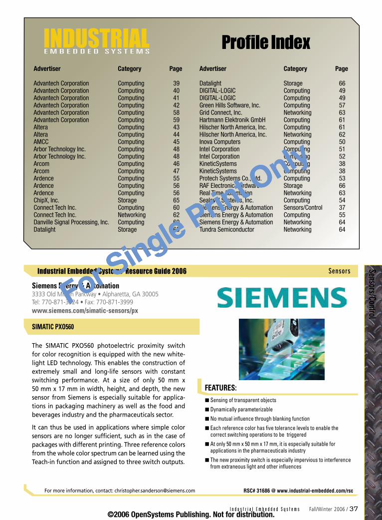
E M B E D D E D S Y S T E M SINDUSTRIAL Profile Index
Advertiser Category Page
Advantech Corporation Computing 39Advantech Corporation Computing 40Advantech Corporation Computing 41Advantech Corporation Computing 42Advantech Corporation Computing 58Advantech Corporation Computing 59Altera Computing 43Altera Computing 44AMCC Computing 45Arbor Technology Inc. Computing 48Arbor Technology Inc. Computing 48Arcom Computing 46Arcom Computing 47Ardence Computing 55Ardence Computing 56Ardence Computing 56ChipX, Inc. Storage 65Connect Tech Inc. Computing 60Connect Tech Inc. Networking 62Danville Signal Processing, Inc. Computing 60Datalight Storage 65
Advertiser Category Page
Datalight Storage 66DIGITAL-LOGIC Computing 49DIGITAL-LOGIC Computing 49Green Hills Software, Inc. Computing 57Grid Connect, Inc. Networking 63Hartmann Elektronik GmbH Computing 61Hilscher North America, Inc. Computing 61Hilscher North America, Inc. Networking 62Inova Computers Computing 50Intel Corporation Computing 51Intel Corporation Computing 52KineticSystems Computing 38KineticSystems Computing 38Protech Systems Co., Ltd. Computing 53RAF Electronic Hardware Storage 66Real Time Automation Networking 63Sealevel Systems, Inc. Computing 54Siemens Energy & Automation Sensors/Control 37Siemens Energy & Automation Computing 55Siemens Energy & Automation Networking 64Tundra Semiconductor Networking 64
I n d u s t r i a l E m b e d d e d S y s t e m s Fall/Winter 2006 / 3�
Industrial Embedded Systems Resource Guide 2006
FEATURES:
Sensors/Control
Sensing of transparent objects
Dynamically parameterizable
No mutual influence through blanking function
Each reference color has five tolerance levels to enable the correct switching operations to be triggered
At only 50 mm x 50 mm x 17 mm, it is especially suitable for applications in the pharmaceuticals industry
The new proximity switch is especially impervious to interference from extraneous light and other influences
n
n
n
n
n
n
Siemens Energy & Automation3333 Old Milton Parkway • Alpharetta, GA 30005 Tel: 770-871-3924 • Fax: 770-871-3999www.siemens.com/simatic-sensors/px
The SIMATIC PXO560 photoelectric proximity switch for color recognition is equipped with the new white-light LED technology. This enables the construction of extremely small and long-life sensors with constant switching performance. At a size of only 50 mm x 50 mm x 17 mm in width, height, and depth, the new sensor from Siemens is especially suitable for applica-tions in packaging machinery as well as the food and beverages industry and the pharmaceuticals sector.
It can thus be used in applications where simple color sensors are no longer sufficient, such as in the case of packages with different printing. Three reference colors from the whole color spectrum can be learned using the Teach-in function and assigned to three switch outputs.
For more information, contact: [email protected] RSC# 31686 @ www.industrial-embedded.com/rsc
SIMATIC PXO560
Sensors
©2006 OpenSystems Publishing. Not for distribution.
For Single Print Only

38 / Fall/Winter 2006 I n d u s t r i a l E m b e d d e d S y s t e m s
Industrial Embedded Systems Resource Guide 2006
FEATURES:
FEATURES:
Industrial Embedded Systems Resource Guide 2006
Com
putin
g
256 digital I/O channels
128 base card channels
Four mezzanine card sites for added I/O capability such as TTL and differential I/O, isolated I/O, etc.
Change of state and pattern recognition
Programmable contact-bounce suppression on inputs
Input and output strobes
n
n
n
n
n
n
KineticSystems900 N. State Street • Lockport, IL 60441 Tel: 815-838-0005 • Fax: 815-838-4424www.kscorp.com
The CP387 is a single-width, 6U, CompactPCI module with up to 256 digital input/output channels. The CP387 baseboard supports 128 channels of TTL I/O. Four mez-zanine card sites can be populated with an assortment of I/O options such as isolated input, isolated output, relay output, AC switch output, and differential I/O to extend the capability of the CP387. The mezzanine card concept allows multiple digital I/O types to be config-ured within a single module to match the application requirements.
Pattern recognition and change-of-state detection are included. Both operations can be used on the base card as well as span to the mezzanine channels. Input and output strobes are provided for connection to external sources.
For more information, contact: [email protected] RSC# 21633 @ www.industrial-embedded.com/rsc
Eight frequency counter channels
Frequency range from 0.06 Hz to 100 kHz
Differential and TTL inputs provided
Differential input range 20 mV to 20 V
Programmable AC/DC differential inputs
Programmable observation window: 1 ms to 1.025 sec
n
n
n
n
n
n
KineticSystems900 N. State Street • Lockport, IL 60441 Tel: 815-838-0005 • Fax: 815-838-4424www.kscorp.com
The P635 is a single-width, 3U, PXI bus module with eight frequency measurement channels. This coun-ter module can be used to monitor a variety of pulse sources. Moreover, its unique circuitry allows monitor-ing of a wide range of frequencies without changing any module settings.
TTL inputs are provided as well as differential input cir-cuits, with a programmable high-frequency noise filter and hysteresis to provide high noise immunity. The ana-log path also includes programmable gain control. The gain control sets the input switching threshold, while the filter provides a 3 dB rolloff at 50 kHz. AC or DC coupling of the differential inputs is programmable on a per-channel basis.
For more information, contact: [email protected] RSC# 24986 @ www.industrial-embedded.com/rsc
Dataacquisition
PXI Product-P635
Dataacquisition
cPCI Product-CP387
©2006 OpenSystems Publishing. Not for distribution.
For Single Print Only

FEATURES:
Industrial Embedded Systems Resource Guide 2006
Computing
I n d u s t r i a l E m b e d d e d S y s t e m s Fall/Winter 2006 / 39
AIMB-762
AIMB-762 is an industrial ATX motherboard built on the Intel® 945G Express. The AIMB-762 supports dual-core Intel® Pentium® D and Intel® Pentium® 4 processors and delivers system enhancements through high-band-width interfaces such as dual-channel DDR2 533/677 memory, PCI Express (PCIe) interfaces, Serial ATA II and Hi-Speed USB 2.0 connectivity. It also features a cost-effective graphics engine with outstanding graphics performance, impressive visual quality, and flexible dis-play options.
The AIMB-762 features excellent graphics performance with integrated graphics and an exclusive PCIe x16 expansion slot. The onboard integrated VGA controller along with the unique Intel® Graphics Media Accelera-tor 950 (Intel® GMA 950) are equipped to share memory up to 224 MB and offer a cost-effective graphics solu-tion with superior multimedia and 3D performance. Through the integrated Intel® GMA 950 and DVO out-puts, the AIMB-762 supports a dual independent dis-play with flexible video output options, such as DVI and LVDS. When higher graphics computing abilities are needed, the AIMB-762 provides an advanced PCIe x16 expansion interface that delivers greater than 3.5 times the bandwidth over the traditional AGP 8X interface to support the latest high-performance graphics cards.
Incorporating the Intel® ICH7R chipset, the AIMB-762 comes with rich expandability. Several outstanding I/O expansion options are available: one PCIe x16 and one PCIe x4 interfaces, as well as five 32-bit/33 MHz PCI slots. With up to 8 GBps concurrent, bidirectional band-width, the PCIe x16 interface operates as a graphics, or a general purpose I/O. The 32-bit/33 MHz PCI sup-ports most current expansion devices. To satisfy increas-ing demands for data transfer speeds, the AIMB-762 provides eight Hi-Speed USB 2.0 connectivity and four onboard Serial ATA II ports with transfer rates up to 3 Gbps for a wide range of peripheral devices.
Intel® 945G chipset 800 MHz FSB
Dual-channel DDR2 533/667 SDRAM up to 4 GB
Chipset integrated VGA sharing 224 MB system memory
PCIe x16 slot for VGA card
Four SATA II ports with 300 MB transfer rate and (software RAID 0, 1, 10, 5)
Supports dual 10/100/1000BASE-T Ethernet via dedicated PCIe x1 bus
Compatible with Advantech’s 2U, 4U, 5U, and 7U chassis
n
n
n
n
n
n
n
Industrialsystems
RSC# 31211 @ www.industrial-embedded.com/rscFor more information, contact: [email protected]
Advantech Corporation15375 Barranca Parkway, Suite A-106 • Irvine, CA 92618 Tel: 949-789-7178 • Fax: 949-789-7179www.advantech.com
©2006 OpenSystems Publishing. Not for distribution.
For Single Print Only

FEATURES:
Industrial Embedded Systems Resource Guide 2006
Com
putin
g
�0 / Fall/Winter 2006 I n d u s t r i a l E m b e d d e d S y s t e m s
ARK Series
Industrialsystems
Advantech Corporation15375 Barranca Parkway, Suite A-106 • Irvine, CA 92618 Tel: 949-789-7178 • Fax: 949-789-7179www.advantech.com
ARK-3380 Series of Embedded Box Computers are designed for space-critical embedded applications requiring powerful computing capability, fanless oper-ation, low power use, extreme reliability and rugged-ness, flexible I/O configuration, and long product life support. Designed to offer maximum computing power in the most efficient footprint possible, the ARK-3380 Series is fully customizable, offering a range of process-ing engines, storage, connectivity, and I/O configura-tions that allow integrators to put scalable computing power exactly where needed.
Featuring Low Voltage Intel® Celeron/Pentium® M processors to 1.4 GHz and a footprint of only 10.41" x 2.72" x 5.4" with protected housing, the rugged ARK-3380 Series can be mounted inside machinery or other equipment/housing, or standalone by wall or DIN rail mount. The series accepts a wide range of power supplies (DC power-in) and choice of CFC SSD drive or 2.5" HDD. The cast aluminum chassis not only provides great protection from EMI, shock (5 g), vibration, dust, cold, and heat, but also acts as a functional heat sink to ensure low temperature operation (-20 °C ~ + 60 °C).
The ARK-3380 Series includes application-ready plat-forms designed for specific vertical market applications. The ARK-3380 offers comprehensive multimedia I/O support featuring dual display, TV-out, DVI, LVDS, and SC97 stereo audio. This series targets applications like POS/POI, intelligent traffic monitoring, and machine vision systems. The ARK-3381 comes with multiple I/O support featuring 5x RS-232/422/484, 1x RS-232, and 1x RS-232 (Rx/Tx only without handshaking). The ARK-3381 supports applications for environment and facilities monitoring, kiosks, tolling and ticketing, and entrance controls as well as medical devices with mul-tiple device connectivity. The ARK-3382 supports inten-sive networking capability by offering 4x 10/100 BASE-T Ethernet plus LAN bypass function support. This makes the ARK-3382 ideal for industrial and security gateway applications that require intensive LAN communication, such as firewall or VPN.
Built-in Intel® Ultra Low Voltage Celeron® or Low Voltage Intel® Pentium® M processor
200-pin DDR SDRAM (up to 1G)
Up to 4x 10/100BASE-T Ethernet, 1x PS/2, 1x USB 2.0, 2x RS-232, 5x RS-232/422/485
One CompactFlash card slot; support 2.5" HDD
Sealed construction with fanless operation
Antivibration to ensure maximum reliability
Easy integration, easy maintenance, few parts, with wide range of power source
n
n
n
n
n
n
n
RSC# 31211 @ www.industrial-embedded.com/rscFor more information, contact: [email protected]
©2006 OpenSystems Publishing. Not for distribution.
For Single Print Only

FEATURES:
Industrial Embedded Systems Resource Guide 2006
Computing
I n d u s t r i a l E m b e d d e d S y s t e m s Fall/Winter 2006 / �1
PCE-7210
PCE-7210, an SHB Express (also referred to as PICMG 1.3) System Host Board with support for dual Intel® Xeon®/ Low Voltage Intel Xeon processors up to 3.6 GHz. Equipped with the Intel E7520 chipset and Intel 6300ESB I/O controller, this optimized server board supports up to 8 GBps of dual-channel DDR2-400 ECC registered RAM. The PCE-7210 provides two PCI Express (PCIe) x8 and one PCIe x4 connections, offering up to 10 GBps of bandwidth to the SHB Express backplane. Another PCIe x4 is linked to a Broadcom BCM5715C dual-port Gigabit LAN chip, enabling high throughputs for heavily loaded network environments. Addition-ally, an optional IPMI module provides comprehensive platform management. The PCE-7210’s versatility and capability to support larger data sets applications make it ideal for a variety of high-performance computing and server applications.
PCE-7210 is based on the Intel E7520 chipset, which consists of the E7520 Memory Controller Hub (MCH) and the 6300ESB I/O Controller Hub. This server chipset provides an 800 MHz FSB connection to dual Intel Xeon or Low Voltage Intel Xeon processors with 2 MB of L2 cache. With four DIMM slots, the PCE-7210 supports up to 8 GBps of dual-channel DDR2-400 ECC Registered DIMM and is ideally suited to a broad range of memory intensive applications. Dual DDR2-400 memory chan-nels deliver a maximum memory bandwidth of 6.4 GBps while decreasing power consumption. Additionally, ECC Registered DIMM includes memory error detection and correction, which is crucial in industrial environments.
The PCE-7210 features two x8 and one x4 PCIe connec-tions to provide a substantial 10 GBps of bandwidth to the backplane. Each PCIe x8 interface delivers up to 4 GBps of throughput while each PCIe x4 interface increases I/O bandwidth up to 2 GBps. The PCE-7210 also offers one PCIe x4 dedicated to a Broadcom BCM5715C dual-port Gigabit LAN chip for high network through-put. The combination of the PCE-7210 SHB and the 13-slot backplane PCE-7B13-64A1E enables the SHB system to provide two PCIe x8, six PCI-X, and four PCI expan-sion slots for high-bandwidth add-on cards.
PICMG 1.3 compliant
Supports single/dual socket 604 Intel® Xeon®/LV Xeon® 800 MHz FSB
Supports dual-channel DDR2 400 ECC registered SDRAM up to 8 GB
Two PCIe x8 and one PCIe x4 links to backplane
Dual Gigabit Ethernet via PCIe x4 port
Onboard IPMI module (optional)
Two SATA HDDs support S/W SATA Raid
n
n
n
n
n
n
n
Industrialsystems
RSC# 31672 @ www.industrial-embedded.com/rscFor more information, contact: [email protected]
Advantech Corporation15375 Barranca Parkway, Suite A-106 • Irvine, CA 92618 Tel: 949-789-7178 • Fax: 949-789-7179www.advantech.com
©2006 OpenSystems Publishing. Not for distribution.
For Single Print Only
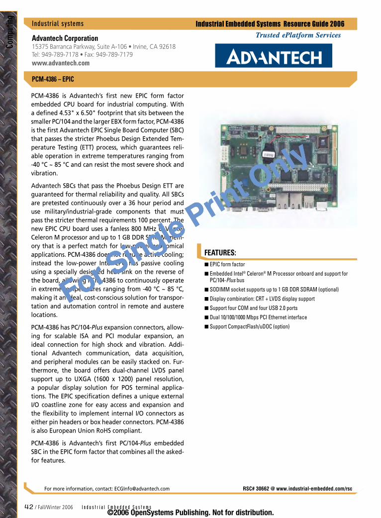
FEATURES:
Industrial Embedded Systems Resource Guide 2006
Com
putin
g
�2 / Fall/Winter 2006 I n d u s t r i a l E m b e d d e d S y s t e m s
PCM-4386 – EPIC
PCM-4386 is Advantech’s first new EPIC form factor embedded CPU board for industrial computing. With a defined 4.53" x 6.50" footprint that sits between the smaller PC/104 and the larger EBX form factor, PCM-4386 is the first Advantech EPIC Single Board Computer (SBC) that passes the stricter Phoebus Design Extended Tem-perature Testing (ETT) process, which guarantees reli-able operation in extreme temperatures ranging from -40 °C ~ 85 °C and can resist the most severe shock and vibration.
Advantech SBCs that pass the Phoebus Design ETT are guaranteed for thermal reliability and quality. All SBCs are pretested continuously over a 36 hour period and use military/industrial-grade components that must pass the stricter thermal requirements 100 percent. The new EPIC CPU board uses a fanless 800 MHz ULV Intel Celeron M processor and up to 1 GB DDR SDRAM mem-ory that is a perfect match for low-power economical applications. PCM-4386 does not require active cooling; instead the low-power Intel CPU has passive cooling using a specially designed heat sink on the reverse of the board, allowing PCM-4386 to continuously operate in extreme temperatures ranging from -40 °C ~ 85 °C, making it an ideal, cost-conscious solution for transpor-tation and automation control in remote and austere locations.
PCM-4386 has PC/104-Plus expansion connectors, allow-ing for scalable ISA and PCI modular expansion, an ideal connection for high shock and vibration. Addi-tional Advantech communication, data acquisition, and peripheral modules can be easily stacked on. Fur-thermore, the board offers dual-channel LVDS panel support up to UXGA (1600 x 1200) panel resolution, a popular display solution for POS terminal applica-tions. The EPIC specification defines a unique external I/O coastline zone for easy access and expansion and the flexibility to implement internal I/O connectors as either pin headers or box header connectors. PCM-4386 is also European Union RoHS compliant.
PCM-4386 is Advantech’s first PC/104-Plus embedded SBC in the EPIC form factor that combines all the asked-for features.
EPIC form factor
Embedded Intel® Celeron® M Processor onboard and support for PC/104-Plus bus
SODIMM socket supports up to 1 GB DDR SDRAM (optional)
Display combination: CRT + LVDS display support
Support four COM and four USB 2.0 ports
Dual 10/100/1000 Mbps PCI Ethernet interface
Support CompactFlash/uDOC (option)
n
n
n
n
n
n
n
Industrialsystems
Advantech Corporation15375 Barranca Parkway, Suite A-106 • Irvine, CA 92618 Tel: 949-789-7178 • Fax: 949-789-7179www.advantech.com
RSC# 30662 @ www.industrial-embedded.com/rscFor more information, contact: [email protected]
©2006 OpenSystems Publishing. Not for distribution.
For Single Print Only

FEATURES:
Industrial Embedded Systems Resource Guide 2006
Computing
I n d u s t r i a l E m b e d d e d S y s t e m s Fall/Winter 2006 / �3
RSC# 31385 @ www.industrial-embedded.com/rsc
Nios II Dev. Kit, Cyclone II Edition
For more information, contact: [email protected]
Industrialsystems
Altera Corporation101 Innovation Drive • San Jose, CA 95134 Tel: 408-544-7000 • Fax: 408-544-6411www.altera.com
®
Altera® Cyclone® II FPGAs are optimized for low cost, extending the reach of FPGAs further into cost-sensitive, high-volume applications and continuing the success of the first-generation Cyclone device family. Cyclone II FPGAs offer a customer-defined feature set, industry-leading performance, and low power consumption. They also offer greatly increased density and more fea-tures, all at significantly lower cost. Featuring up to 150 embedded 18 x 18 multipliers, Cyclone II FPGAs can be used alone or as Digital Signal Processing (DSP) copro-cessors to improve price-to-performance ratios for DSP applications, including video and image processing, communications systems, and common DSP functions.
The Nios® II Development Kit, Cyclone II Edition, offers a variety of Intellectual Property (IP) cores to speed development, including three Nios II 32-bit RISC processors. The Nios II processors – fast, standard, and economy – are each optimized for a specific price and performance range, allowing designers to choose a system configuration that is an exact fit for their embedded needs. All three processors use the same instruction set architecture and are 100 percent binary code compatible. Nios II processors can be added to a designer’s system using the SOPC Builder system devel-opment tool in the Quartus® II development software. This kit includes 12 months of upgrades so you can keep your system up-to-date with the latest enhancements to the Nios II processor, peripherals, and system design tools. This development kit is now RoHS-compliant.
Visit www.altera.com/nios for more information.
Complete embedded FPGA development environment featuring the versatile Nios II embedded processor and the low-cost Cyclone II family
Embedded software development tools:
Nios II Integrated Development Environment (IDE) and debugger, Nios II Instruction Set Simulator (ISS)
GNU tool chain, MicroC/OS-II RTOS, and LightweightIP TCP/IP stack software
Hardware design tools, including the Quartus II design software with the SOPC Builder system development tool
Library of standard embedded IP cores, including:
Three Nios II 32-bit RISC CPU cores (fast, standard, economy)
DDR SRAM controller, timer, UART, SPI, JTAG UART, GPIO, DMA, Ethernet interface, interface-to-user logic, custom instruction, and more
Complete embedded development board featuring:
Cyclone II EP2C35 FPGA and 10/100 Ethernet PHY/MAC
1 MB SSRAM, 16 MB DDR SDRAM, 16 MB flash, JTAG connectors for FPGA and CPLD, Mictor trace/debug connector, 32-bit PMC headers
No license or royalty fees when developing with the Nios II processor in Altera FPGAs and HardCopy® series structured ASICs
n
n
–
–
n
n
–
–
n
–
–
n
©2006 OpenSystems Publishing. Not for distribution.
For Single Print Only
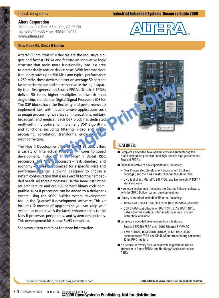
FEATURES:
Industrial Embedded Systems Resource Guide 2006
Com
putin
g
�� / Fall/Winter 2006 I n d u s t r i a l E m b e d d e d S y s t e m s
Nios II Dev. Kit, Stratix II Edition
Industrialsystems
Altera Corporation101 Innovation Drive • San Jose, CA 95134 Tel: 408-544-7000 • Fax: 408-544-6411www.altera.com
®
RSC# 31386 @ www.industrial-embedded.com/rsc
Altera® 90 nm Stratix® II devices are the industry’s big-gest and fastest FPGAs and feature an innovative logic structure that packs more functionality into less area to dramatically reduce device costs. With internal clock frequency rates up to 500 MHz and typical performance > 250 MHz, these devices deliver on average 50 percent faster performance and more than twice the logic capac-ity than first-generation Stratix FPGAs. Stratix II FPGAs deliver 50 times higher multiplier bandwidth than single-chip, standalone Digital Signal Processors (DSPs). The DSP blocks have the flexibility and performance to implement fast, arithmetic-intensive applications such as image processing, wireless communications, military, broadcast, and medical. Each DSP block has dedicated multiwidth multipliers to implement DSP algorithms and functions, including filtering, video and image processing, correlation, transforms, encryption, and error correction.
The Nios II Development Kit, Stratix II Edition, offers a variety of Intellectual Property (IP) cores to speed development, including three Nios® II 32-bit RISC processors. The Nios II processors – fast, standard, and economy – are each optimized for a specific price and performance range, allowing designers to choose a system configuration that is an exact fit for their embed-ded needs. All three processors use the same instruction set architecture and are 100 percent binary code com-patible. Nios II processors can be added to a designer’s system using the SOPC Builder system development tool in the Quartus® II development software. This kit includes 12 months of upgrades so you can keep your system up-to-date with the latest enhancements to the Nios II processor, peripherals, and system design tools. This development kit is now RoHS-compliant.
See www.altera.com/nios for more information.
For more information, contact: [email protected]
Complete embedded development environment featuring the Nios II embedded processor and high-density, high-performance Stratix II FPGAs
Embedded software development tools, including:
Nios II Integrated Development Environment (IDE) and debugger, and the Nios II Instruction Set Simulator (ISS)
GNU tool chain, MicroC/OS-II RTOS, and LightweightIP TCP/IP stack software
Hardware design tools, including the Quartus II design software, with the SOPC Builder system development tool
Library of standard embedded IP cores, including:
Three Nios II 32-bit RISC CPU cores (fast, standard, economy)
DDR SRAM controller, timer, UART, SPI, JTAG UART, GPIO, DMA, Ethernet interface, interface-to-user logic, custom instruction, and more
Complete embedded development board featuring:
Stratix II EP2S60 FPGA and 10/100 Ethernet PHY/MAC
1 MB SSRAM, 16 MB DDR SDRAM, 16 MB flash, JTAG connectors for FPGA and CPLD, Mictor trace/debug connector, 32-bit PMC headers
No license or royalty fees when developing with the Nios II processor in Altera FPGAs and HardCopy® series structured ASICs
n
n
–
–
n
n
–
–
n
–
–
n
©2006 OpenSystems Publishing. Not for distribution.
For Single Print Only

Industrial Embedded Systems Resource Guide 2006
Computing
Technology
130 nm CMOS
IEEE 1588 Precision Timing Protocol
Configurable autoreloading 15-channel Chameleon Timer/PWM controller
One 10-bit 30 MSps DAC
One 8-input 10-bit 300 ksps ADC
Three USB 1.1/2.0 Full-Speed compatible ports with integrated PHYs and two CAN 2.0b ports
Frequency
CPU: 166-416 MHz
PLB: 166 MHz maximum
OPB: 83 MHz maximum
External bus: 83 MHz maximum
Power dissipation
< 1.5 W maximum (at 416 MHz), <= 0.60 W typical
Performance (estimate)
252 Dhrystone 2.1 MIPS at 166 MHz
632 Dhrystone 2.1 MIPS at 416 MHz
Case temperature range
Industrial range: -40 °C to +85 °C
Extended range: -40 °C to +105 °C
Power supply
1.5 V (internal logic), 3.3 V (I/O), 3.3 V
Packaging
324-pin PBGA 23 mm x 23 mm (with 1 mm ball pitch)
n
–
n
n
n
n
n
n
–
–
–
–
n
–
n
–
–
n
–
–
n
–
n
–
FEATURES:
I n d u s t r i a l E m b e d d e d S y s t e m s Fall/Winter 2006 / �5
PPC405EZ
With on-chip speed of up to 416 MHz; a wide 64-bit on-chip bus; flexible on-chip and off-chip memory architecture; a unique combination of ADC, DAC, and configurable Chameleon Timer©/PWM; and a diverse connectivity package, AMCC’s PPC405EZ embedded processor provides a low-power small-footprint solu-tion-on-a-chip for a wide range of high-performance, cost-constrained embedded applications.
This SoC is built for data and I/O traffic. The PowerPC 405 processor offers computing power in the range from 252 DMIPS to 632 DMIPS. Due to the attention paid to high performance on-chip busing, this process-ing performance is highly unaffected by the heavy DMA I/O traffic.
The PPC405EZ’s connectivity package consists of one Fast Ethernet port with integrated IEEE 1588 Precision Timing Protocol controller, three USB 1.1/2.0 Full-Speed compatible ports with integrated PHYs, and two CAN 2.0b ports. The key features making up the industrial package are one 8-input 10-bit 300 ksps ADC, one 10-bit 30 Msps DAC, and a configurable autoreloading 15-channel Chameleon Timer/PWM controller that sig-nificantly offloads the CPU and software for complex timing and waveform generation.
The PPC405EZ is unique in offering this high level of compute processing, precision timing, and networking options in a single SoC. The PPC405EZ, with its shift away from traditional on-chip flash in favor of on-chip SRAM and away from traditional external DRAM in favor of external PSRAMs and CRAMs enables system designers to break through the 80 MHz flash MCU barrier and achieve usable high performance and low power at a reduced eBOM. Cost-effective 252-632 DMIPS class sys-tems – ranging from a two-chip solution (PPC405EZ+SPI boot device) to Linux-on-a-chip and multichip mul-timaster implementations – can be built around the PPC405EZ SoC fed by a single 33-50 MHz oscillator.
Industrialsystems
RSC# 31674 @ www.industrial-embedded.com/rscFor more information, contact: [email protected]
AMCC215 Moffet Park Drive • Sunnyvale, CA 94089 Tel: 800-840-6055 • Fax: 408-542-8601www.amcc.com
©2006 OpenSystems Publishing. Not for distribution.
For Single Print Only
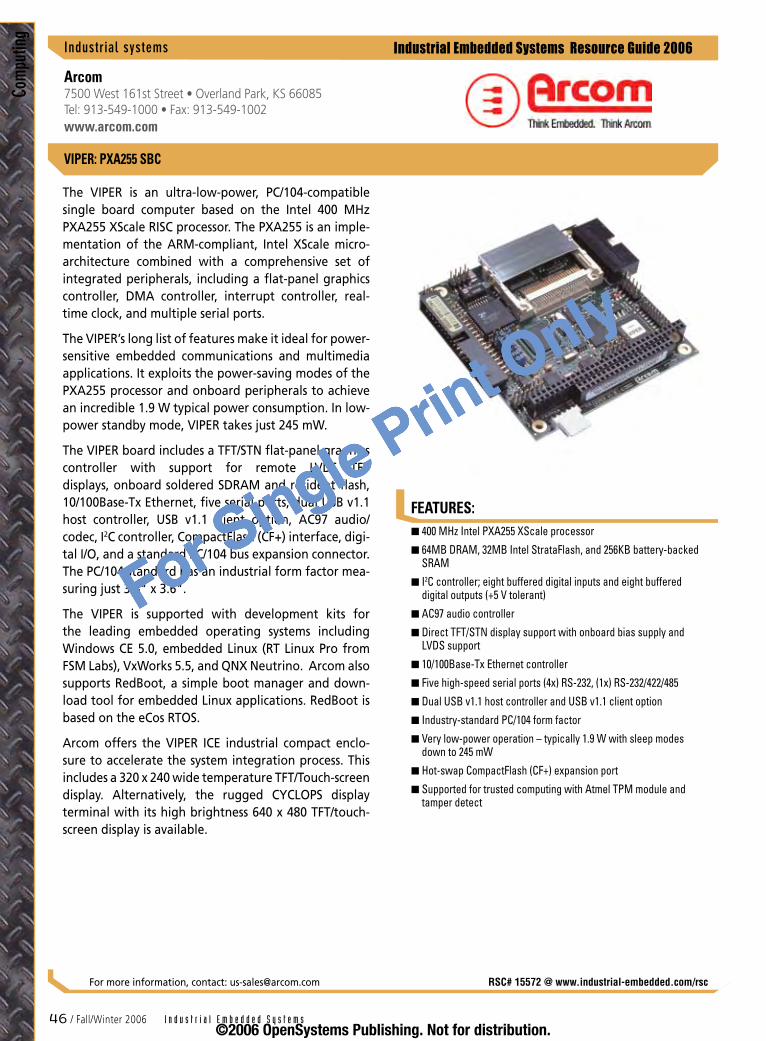
FEATURES:
Industrial Embedded Systems Resource Guide 2006
Com
putin
g
�� / Fall/Winter 2006 I n d u s t r i a l E m b e d d e d S y s t e m s
VIPER: PXA255 SBC
Industrialsystems
Arcom7500 West 161st Street • Overland Park, KS 66085 Tel: 913-549-1000 • Fax: 913-549-1002www.arcom.com
The VIPER is an ultra-low-power, PC/104-compatible single board computer based on the Intel 400 MHz PXA255 XScale RISC processor. The PXA255 is an imple-mentation of the ARM-compliant, Intel XScale micro-architecture combined with a comprehensive set of integrated peripherals, including a flat-panel graphics controller, DMA controller, interrupt controller, real-time clock, and multiple serial ports.
The VIPER’s long list of features make it ideal for power-sensitive embedded communications and multimedia applications. It exploits the power-saving modes of the PXA255 processor and onboard peripherals to achieve an incredible 1.9 W typical power consumption. In low-power standby mode, VIPER takes just 245 mW.
The VIPER board includes a TFT/STN flat-panel graphics controller with support for remote LVDS TFT displays, onboard soldered SDRAM and resident flash, 10/100Base-Tx Ethernet, five serial ports, dual USB v1.1 host controller, USB v1.1 client option, AC97 audio/codec, I2C controller, CompactFlash (CF+) interface, digi-tal I/O, and a standard PC/104 bus expansion connector. The PC/104 standard has an industrial form factor mea-suring just 3.8" x 3.6".
The VIPER is supported with development kits for the leading embedded operating systems including Windows CE 5.0, embedded Linux (RT Linux Pro from FSM Labs), VxWorks 5.5, and QNX Neutrino. Arcom also supports RedBoot, a simple boot manager and down-load tool for embedded Linux applications. RedBoot is based on the eCos RTOS.
Arcom offers the VIPER ICE industrial compact enclo-sure to accelerate the system integration process. This includes a 320 x 240 wide temperature TFT/Touch-screen display. Alternatively, the rugged CYCLOPS display terminal with its high brightness 640 x 480 TFT/touch-screen display is available.
400 MHz Intel PXA255 XScale processor
64MB DRAM, 32MB Intel StrataFlash, and 256KB battery-backed SRAM
I2C controller; eight buffered digital inputs and eight buffered digital outputs (+5 V tolerant)
AC97 audio controller
Direct TFT/STN display support with onboard bias supply and LVDS support
10/100Base-Tx Ethernet controller
Five high-speed serial ports (4x) RS-232, (1x) RS-232/422/485
Dual USB v1.1 host controller and USB v1.1 client option
Industry-standard PC/104 form factor
Very low-power operation – typically 1.9 W with sleep modes down to 245 mW
Hot-swap CompactFlash (CF+) expansion port
Supported for trusted computing with Atmel TPM module and tamper detect
n
n
n
n
n
n
n
n
n
n
n
n
RSC# 15572 @ www.industrial-embedded.com/rscFor more information, contact: [email protected]
©2006 OpenSystems Publishing. Not for distribution.
For Single Print Only
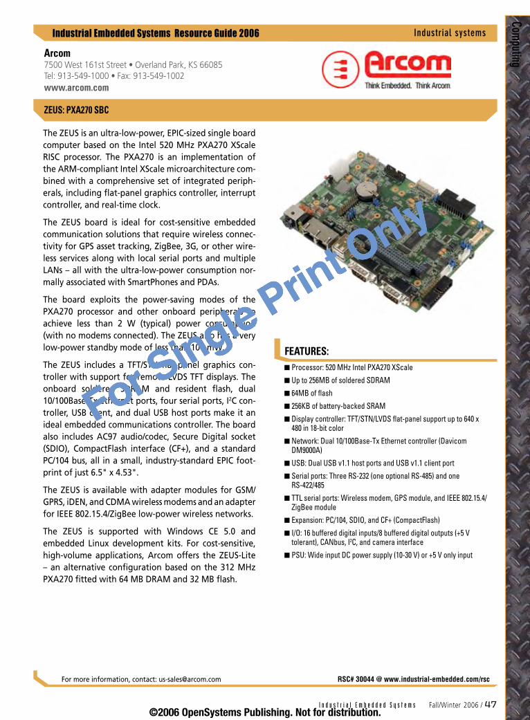
FEATURES:
Industrial Embedded Systems Resource Guide 2006
Computing
I n d u s t r i a l E m b e d d e d S y s t e m s Fall/Winter 2006 / ��
ZEUS: PXA270 SBC
The ZEUS is an ultra-low-power, EPIC-sized single board computer based on the Intel 520 MHz PXA270 XScale RISC processor. The PXA270 is an implementation of the ARM-compliant Intel XScale microarchitecture com-bined with a comprehensive set of integrated periph-erals, including flat-panel graphics controller, interrupt controller, and real-time clock.
The ZEUS board is ideal for cost-sensitive embedded communication solutions that require wireless connec-tivity for GPS asset tracking, ZigBee, 3G, or other wire-less services along with local serial ports and multiple LANs – all with the ultra-low-power consumption nor-mally associated with SmartPhones and PDAs.
The board exploits the power-saving modes of the PXA270 processor and other onboard peripherals to achieve less than 2 W (typical) power consumption (with no modems connected). The ZEUS also has a very low-power standby mode of less than 100 mW.
The ZEUS includes a TFT/STN flat-panel graphics con-troller with support for remote LVDS TFT displays. The onboard soldered SDRAM and resident flash, dual 10/100Base-Tx Ethernet ports, four serial ports, I2C con-troller, USB client, and dual USB host ports make it an ideal embedded communications controller. The board also includes AC97 audio/codec, Secure Digital socket (SDIO), CompactFlash interface (CF+), and a standard PC/104 bus, all in a small, industry-standard EPIC foot-print of just 6.5" x 4.53".
The ZEUS is available with adapter modules for GSM/GPRS, iDEN, and CDMA wireless modems and an adapter for IEEE 802.15.4/ZigBee low-power wireless networks.
The ZEUS is supported with Windows CE 5.0 and embedded Linux development kits. For cost-sensitive, high-volume applications, Arcom offers the ZEUS-Lite – an alternative configuration based on the 312 MHz PXA270 fitted with 64 MB DRAM and 32 MB flash.
Processor: 520 MHz Intel PXA270 XScale
Up to 256MB of soldered SDRAM
64MB of flash
256KB of battery-backed SRAM
Display controller: TFT/STN/LVDS flat-panel support up to 640 x 480 in 18-bit color
Network: Dual 10/100Base-Tx Ethernet controller (Davicom DM9000A)
USB: Dual USB v1.1 host ports and USB v1.1 client port
Serial ports: Three RS-232 (one optional RS-485) and one RS-422/485
TTL serial ports: Wireless modem, GPS module, and IEEE 802.15.4/ZigBee module
Expansion: PC/104, SDIO, and CF+ (CompactFlash)
I/O: 16 buffered digital inputs/8 buffered digital outputs (+5 V tolerant), CANbus, I2C, and camera interface
PSU: Wide input DC power supply (10-30 V) or +5 V only input
n
n
n
n
n
n
n
n
n
n
n
n
Industrialsystems
RSC# 30044 @ www.industrial-embedded.com/rscFor more information, contact: [email protected]
Arcom7500 West 161st Street • Overland Park, KS 66085 Tel: 913-549-1000 • Fax: 913-549-1002www.arcom.com
©2006 OpenSystems Publishing. Not for distribution.
For Single Print Only
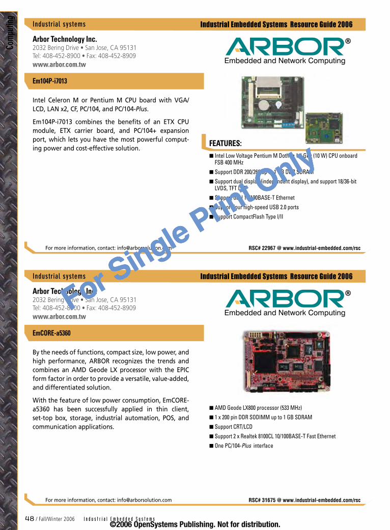
�8 / Fall/Winter 2006 I n d u s t r i a l E m b e d d e d S y s t e m s
Industrial Embedded Systems Resource Guide 2006
FEATURES:
Industrial Embedded Systems Resource Guide 2006
Com
putin
g
Intel Low Voltage Pentium M Dothan 1.4 GHz (10 W) CPU onboard FSB 400 MHz
Support DDR 200/266 up to 1 GB DDR SDRAM
Support dual display (independent display), and support 18/36-bit LVDS, TFT LCD
Support dual 10/100BASE-T Ethernet
Support four high-speed USB 2.0 ports
Support CompactFlash Type I/II
n
n
n
n
n
n
Arbor Technology Inc.2032 Bering Drive • San Jose, CA 95131 Tel: 408-452-8900 • Fax: 408-452-8909www.arbor.com.tw
Intel Celeron M or Pentium M CPU board with VGA/LCD, LAN x2, CF, PC/104, and PC/104-Plus.
Em104P-i7013 combines the benefits of an ETX CPU module, ETX carrier board, and PC/104+ expansion port, which lets you have the most powerful comput-ing power and cost-effective solution.
For more information, contact: [email protected] RSC# 22967 @ www.industrial-embedded.com/rsc
Industrialsystems
Em104P-i7013
AMD Geode LX800 processor (533 MHz)
1 x 200 pin DDR SODIMM up to 1 GB SDRAM
Support CRT/LCD
Support 2 x Realtek 8100CL 10/100BASE-T Fast Ethernet
One PC/104-Plus interface
n
n
n
n
n
Arbor Technology Inc.2032 Bering Drive • San Jose, CA 95131 Tel: 408-452-8900 • Fax: 408-452-8909www.arbor.com.tw
By the needs of functions, compact size, low power, and high performance, ARBOR recognizes the trends and combines an AMD Geode LX processor with the EPIC form factor in order to provide a versatile, value-added, and differentiated solution.
With the feature of low power consumption, EmCORE-a5360 has been successfully applied in thin client, set-top box, storage, industrial automation, POS, and communication applications.
For more information, contact: [email protected] RSC# 31675 @ www.industrial-embedded.com/rsc
Industrialsystems
EmCORE-a5360
©2006 OpenSystems Publishing. Not for distribution.
For Single Print Only
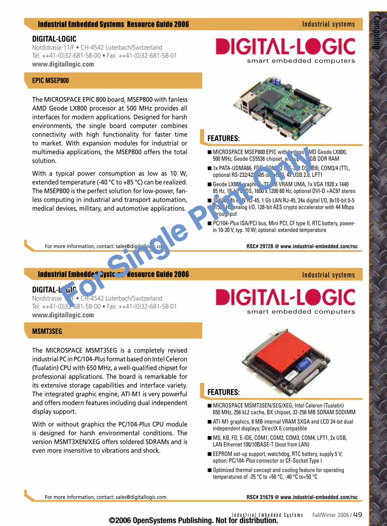
I n d u s t r i a l E m b e d d e d S y s t e m s Fall/Winter 2006 / �9
Industrial Embedded Systems Resource Guide 2006
Industrial Embedded Systems Resource Guide 2006
FEATURES:
Computing
MICROSPACE MSEP800 EPIC with fanless AMD Geode LX800, 500 MHz, Geode CS5536 chipset, and up to 1 GB DDR RAM
1x PATA-UDMA66, FDD, COM1/2 (RS-232 DSUB9), COM3/4 (TTL, optional RS-232/422/485 isolated), 4x USB 2.0, LPT1
Geode LX800 graphics, 32 MB VRAM UMA, 1x VGA 1920 x 1440 85 Hz, 18-bit LVDS, 1600 x 1200 60 Hz; optional DVI-D +AC97 stereo
10/100 Mb LAN RJ-45, 1 Gb LAN RJ-45, 24x digital I/O, 8x10-bit 0-5 V/500 Hz analog I/O, 128-bit AES crypto accelerator with 44 Mbps throughput
PC/104-Plus ISA/PCI bus, Mini PCI, CF type II, RTC battery, power-in 10-30 V, typ. 10 W; optional: extended temperature
n
n
n
n
n
FEATURES:
DIGITAL-LOGICNordstrasse 11/F • CH-4542 Luterbach/Switzerland Tel: ++41-(0)32-681-58-00 • Fax: ++41-(0)32-681-58-01www.digitallogic.com
The MICROSPACE EPIC 800 board, MSEP800 with fanless AMD Geode LX800 processor at 500 MHz provides all interfaces for modern applications. Designed for harsh environments, the single board computer combines connectivity with high functionality for faster time to market. With expansion modules for industrial or multimedia applications, the MSEP800 offers the total solution.
With a typical power consumption as low as 10 W, extended temperature (-40 °C to +85 °C) can be realized. The MSEP800 is the perfect solution for low-power, fan-less computing in industrial and transport automation, medical devices, military, and automotive applications.
For more information, contact: [email protected] RSC# 29728 @ www.industrial-embedded.com/rsc
EPIC MSEP800
Industrialsystems
MICROSPACE MSMT3SEN/SEG/XEG; Intel Celeron (Tualatin) 650 MHz, 256 kL2 cache, BX chipset, 32-256 MB SDRAM SODIMM
ATI-M1 graphics, 8 MB internal VRAM SXGA and LCD 24-bit dual independent displays; DirectX 6 compatible
MS, KB, FD, E-IDE, COM1, COM2, COM3, COM4, LPT1, 2x USB, LAN Ethernet 100/10BASE-T (boot from LAN)
EEPROM set-up support, watchdog, RTC battery, supply 5 V; option: PC/104-Plus connector or CF-Socket Type I
Optimized thermal concept and cooling feature for operating temperatures of -25 °C to +50 °C, -40 °C to+50 °C
n
n
n
n
n
DIGITAL-LOGICNordstrasse 11/F • CH-4542 Luterbach/SwitzerlandTel: ++41-(0)32-681-58-00 • Fax: ++41-(0)32-681-58-01www.digitallogic.com
The MICROSPACE MSMT3SEG is a completely revised industrial PC in PC/104-Plus format based on Intel Celeron (Tualatin) CPU with 650 MHz, a well-qualified chipset for professional applications. The board is remarkable for its extensive storage capabilities and interface variety. The integrated graphic engine, ATI-M1 is very powerful and offers modern features including dual independent display support.
With or without graphics the PC/104-Plus CPU module is designed for harsh environmental conditions. The version MSMT3XEN/XEG offers soldered SDRAMs and is even more insensitive to vibrations and shock.
For more information, contact: [email protected] RSC# 31679 @ www.industrial-embedded.com/rsc
Industrialsystems
MSMT3SEG
©2006 OpenSystems Publishing. Not for distribution.
For Single Print Only
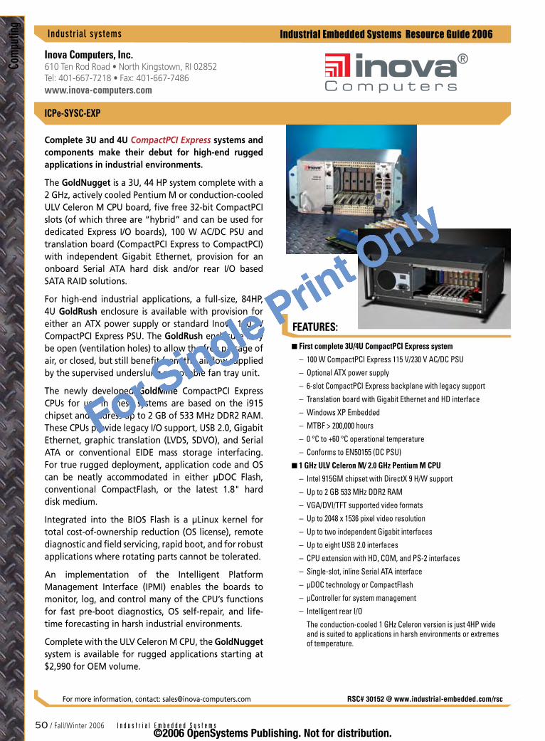
Industrial Embedded Systems Resource Guide 2006
Com
putin
g
FEATURES:
First complete 3U/4U CompactPCI Express system
100 W CompactPCI Express 115 V/230 V AC/DC PSU
Optional ATX power supply
6-slot CompactPCI Express backplane with legacy support
Translation board with Gigabit Ethernet and HD interface
Windows XP Embedded
MTBF > 200,000 hours
0 °C to +60 °C operational temperature
Conforms to EN50155 (DC PSU)
1 GHz ULV Celeron M/ 2.0 GHz Pentium M CPU
Intel 915GM chipset with DirectX 9 H/W support
Up to 2 GB 533 MHz DDR2 RAM
VGA/DVI/TFT supported video formats
Up to 2048 x 1536 pixel video resolution
Up to two independent Gigabit interfaces
Up to eight USB 2.0 interfaces
CPU extension with HD, COM, and PS-2 interfaces
Single-slot, inline Serial ATA interface
µDOC technology or CompactFlash
µController for system management
Intelligent rear I/O
The conduction-cooled 1 GHz Celeron version is just 4HP wide and is suited to applications in harsh environments or extremes of temperature.
n
–
–
–
–
–
–
–
–
n
–
–
–
–
–
–
–
–
–
–
–
50 / Fall/Winter 2006 I n d u s t r i a l E m b e d d e d S y s t e m s
Inova Computers, Inc.610 Ten Rod Road • North Kingstown, RI 02852Tel: 401-667-7218 • Fax: 401-667-7486www.inova-computers.com
ICPe-SYSC-EXP
Complete 3U and 4U CompactPCI Express systems and components make their debut for high-end rugged applications in industrial environments.
The GoldNugget is a 3U, 44 HP system complete with a 2 GHz, actively cooled Pentium M or conduction-cooled ULV Celeron M CPU board, five free 32-bit CompactPCI slots (of which three are “hybrid” and can be used for dedicated Express I/O boards), 100 W AC/DC PSU and translation board (CompactPCI Express to CompactPCI) with independent Gigabit Ethernet, provision for an onboard Serial ATA hard disk and/or rear I/O based SATA RAID solutions.
For high-end industrial applications, a full-size, 84HP, 4U GoldRush enclosure is available with provision for either an ATX power supply or standard Inova 100 W CompactPCI Express PSU. The GoldRush enclosure may be open (ventilation holes) to allow the free passage of air, or closed, but still benefit from the airflow supplied by the supervised underslung removable fan tray unit.
The newly developed GoldMine CompactPCI Express CPUs for use in these systems are based on the i915 chipset and address up to 2 GB of 533 MHz DDR2 RAM. These CPUs provide legacy I/O support, USB 2.0, Gigabit Ethernet, graphic translation (LVDS, SDVO), and Serial ATA or conventional EIDE mass storage interfacing. For true rugged deployment, application code and OS can be neatly accommodated in either µDOC Flash, conventional CompactFlash, or the latest 1.8" hard disk medium.
Integrated into the BIOS Flash is a µLinux kernel for total cost-of-ownership reduction (OS license), remote diagnostic and field servicing, rapid boot, and for robust applications where rotating parts cannot be tolerated.
An implementation of the Intelligent Platform Management Interface (IPMI) enables the boards to monitor, log, and control many of the CPU’s functions for fast pre-boot diagnostics, OS self-repair, and life-time forecasting in harsh industrial environments.
Complete with the ULV Celeron M CPU, the GoldNugget system is available for rugged applications starting at $2,990 for OEM volume.
Industrialsystems
RSC# 30152 @ www.industrial-embedded.com/rscFor more information, contact: [email protected]
©2006 OpenSystems Publishing. Not for distribution.
For Single Print Only

FEATURES:
Industrial Embedded Systems Resource Guide 2006
Computing
I n d u s t r i a l E m b e d d e d S y s t e m s Fall/Winter 2006 / 51
RSC# 31256 @ www.industrial-embedded.com/rsc
667 MHz Front-Side Bus
APIC
Power Management Logic
Shared L2 Cache
Bus Interface
APIC
L1
Cache
Exe
cu
tion
R
eso
urc
es
Arc
h S
tate
Thermal ControlThermal Control
L1
Cache
Exe
cu
tion
R
eso
urc
es
Arc
h S
tate
Configuration of the Intel® Core™ Duo processor shows two complete execution cores and shared L2 cache. Intelligent power management features deliver significantly greater performance-per-watt over previous Intel® single-core processors.
Intel® Core™ Duo Processors
Intel® Core™ Duo processors are members of Intel’s growing product line of multicore processors. These dual-core processors combine the benefits of two high-performance execution cores with intelligent power management features to deliver significantly greater performance-per-watt over previous Intel® processors. Intel’s 65 nm process technology makes it possible to integrate two cores, along with many advanced fea-tures, in one physical package.
Intel Core Duo processors meet the needs of a wide range of low-power embedded applications such as interactive clients and industrial automation equip-ment. While incorporating advanced processor tech-nology, they remain software-compatible with previous 32-bit Intel® architecture processors. Intel Core Duo pro-cessors integrate two execution cores derived from the Intel® Pentium® M processor, whose power efficiency is enabled through significant hardware architecture enhancements in stack management, instruction execu-tion, and branch prediction. Integrating two execution cores enables Intel Core Duo processors to provide sig-nificant performance improvements while remaining in a thermal envelope that is similar to existing Intel Pentium M processors.
Intel Core Duo processors are validated with the Mobile Intel® 945GM Express chipset. This chipset provides greater flexibility for developers of embedded appli-cations by offering improved graphics and increased I/O bandwidth over previous Intel® chipsets, as well as remote asset management capabilities and improved storage speed and reliability. Intel’s comprehensive processor/chipset validation process enables fast deploy-ment of next-generation platforms to help developers maximize competitive advantage while minimizing development risks.
For more information, contact: www.intel.com/design/intarch
Two complete execution cores in one processor package support multithreading and multitasking environments
Dual-core processing efficiently delivers performance while balancing power requirements
Two execution cores share a high-performance, power-optimized 667 MHz front-side bus to access the same chipset memory
Enhanced Intel SpeedStep® technology helps decrease average power consumption and heat production
Intel® Smart Cache Design allows two execution cores to share 2 MB of L2 cache, reducing FSB traffic and enhancing system responsiveness
Intel® Advanced Thermal Manager supports new digital temperature sensors and thermal monitors to enhance thermal monitoring accuracy
Streaming SIMD Extensions 3 (SSE3) provides significant performance enhancement for multimedia applications
Additional instructions help improve thread synchronization, complex arithmetic, graphics, and video encoding
Fully code compatible with existing Intel architecture-based 32-bit application software
Utilizing Intel® Dynamic Power Coordination, application software or OS support balanced platform performance and power dissipation
Embedded life-cycle support protects system investment by enabling extended product availability for embedded and communications customers
A strong ecosystem of hardware and software vendors (intel.com/go/ica) helps developers reduce costs and shorten time to market
n
n
n
n
n
n
n
n
n
n
n
n
Intel Corporation2200 Mission College Blvd. • Santa Clara, CA 95052 Tel: 916-356-3104/800-628-8686www.intel.com/design/intarch
Industrialsystems
©2006 OpenSystems Publishing. Not for distribution.
For Single Print Only

FEATURES:
Industrial Embedded Systems Resource Guide 2006
Com
putin
g
52 / Fall/Winter 2006 I n d u s t r i a l E m b e d d e d S y s t e m s
Intel® Core™ 2 Duo Processors
Intel® Core™ 2 Duo processors, based on Intel® Core™ microarchitecture, include two complete execution cores, shared L2 cache, and intelligent power man-agement features to deliver significantly greater per-formance-per-watt over previous Intel® single-core processors. Intel® 65 nm process technology supports integration of two complete execution cores into one physical package, providing advancements in simulta-neous computing for multithreaded applications and multitasking environments.
Intel Core microarchitecture helps equipment manu-facturers optimally balance processing capabilities within power and space constraints, meeting the needs of a wide range of performance-intensive, low-power embedded applications in smaller form factors. These include interactive clients (that is, point-of-sale termi-nals and ATMs), gaming platforms, industrial control and automation, digital security surveillance, and med-ical imaging. While incorporating advanced processor technology, they remain software compatible with pre-vious IA-32 processors.
The Intel® Core™ 2 Duo Processor E6400 has a core speed of 2.13 GHz, Thermal Design Power (TDP) of 65 W, and is validated with the Intel® Q965 Express chipset. A 1066 MHz FSB provides increased throughput and faster data transfer between physical memory, I/O, and the dual cores. The chipset includes an optimized memory engine for exceptional system performance, and new technologies for enhanced graphics, sound, and man-ageability. Intel® Quiet System Technology within the chipset regulates system and processor fan speeds for a quieter system.
With a core speed of 2.16 GHz and TDP of 34 W, the Intel Core 2 Duo processor T7400 provides a leading perfor-mance-per-watt choice for small form factor embedded systems. It is validated with the Mobile Intel® 945GM Express chipset, which offers excellent graphics, I/O bandwidth, storage speed, reliability, and remote asset management capabilities. The chipset includes an inte-grated 32-bit 3D graphics engine based on Intel® Graph-ics Media Accelerator 950 architecture and up to 4 GB of 400/533/667 MHz DDR2 SODIMM system memory.
Industrialsystems
Intel Corporation2200 Mission College Blvd. • Santa Clara, CA 95052 Tel: 916-356-3104/800-628-8686intel.com/design/intarch
Executes four instructions per clock cycle to improve execution speed and efficiency using an efficient 14-stage pipeline
Intel® Advanced Smart Cache improves system performance by significantly reducing memory latency to frequently used data
Intel® Smart Memory Access optimizes use of available data bandwidth from the memory subsystem to accelerate out-of-order execution
Intel® Advanced Digital Media Boost accelerates execution of SSE/2/3 instructions to significantly improve multimedia performance
Intel® Intelligent Power Capability manages runtime power consumption of execution cores, turning on computing functions only when needed
Intel® Virtualization Technology allows one hardware platform to function as multiple virtual platforms
Provides greater isolation and security between different applications and operating systems for added protection against corruption
Intel® 64 supports 64-bit instructions, providing flexibility for 64-bit and 32-bit applications and operating systems
Digital Thermal Sensor (DTS) measures maximum temperature on the die at any given time
Execute Disable Bit helps prevent some classes of viruses or worms that exploit buffer overrun vulnerabilities
Embedded life-cycle support protects system investment by enabling extended product availability for embedded customers
Intel’s strong vendor ecosystem helps developers cost effectively meet design challenges and shorten time to market (www.intel.com/go/ica)
n
n
n
n
n
n
n
n
n
n
n
n
RSC# 31681 @ www.industrial-embedded.com/rscFor more information, contact: www.intel.com/design/intarch
©2006 OpenSystems Publishing. Not for distribution.
For Single Print Only
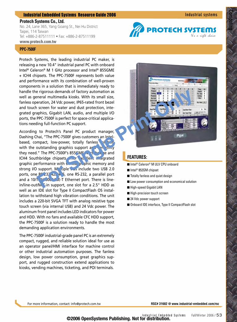
FEATURES:
Industrial Embedded Systems Resource Guide 2006
Computing
I n d u s t r i a l E m b e d d e d S y s t e m s Fall/Winter 2006 / 53
PPC-7500F
Protech Systems, the leading industrial PC maker, is releasing a new 10.4" industrial panel PC with onboard Intel® Celeron® M 1 GHz processor and Intel® 855GME + ICH4 chipsets. The PPC-7500F represents both value and performance with its combination of well-proven components in a solution that is immediately ready to handle the rigorous demands of factory automation as well as general multimedia kiosks. With its small size, fanless operation, 24 Vdc power, IP65-rated front bezel and touch screen for water and dust protection, inte-grated graphics, Gigabit LAN, audio, and multiple I/O ports, the PPC-7500F is perfect for space-critical applica-tions needing full-function PC support.
According to Protech’s Panel PC product manager, Dashing Chai, “The PPC-7500F gives customers an Intel-based, compact, low-power, totally fanless solution with the outstanding graphics support and versatility they need.” The PPC-7500F’s 855GME Northbridge and ICH4 Southbridge chipsets offer excellent integrated graphic performance with 64 MB graphic memory and strong I/O support. Multiple I/Os include two USB 2.0 ports, one RS-232/422/485, one RS-232, a parallel port and a 10/100/1000BASE-T Ethernet port. There is line-in/line-out/MIC-in support, one slot for a 2.5" HDD as well as an IDE slot for Type II CompactFlash OS instal-lation to withstand high vibration conditions. The unit includes a 220-bit SVGA TFT with analog resistive type touch screen (via internal USB) and 24 Vdc power. The aluminum front panel includes LED indicators for power and HDD. With no fans and available CFC HDD support, the PPC-7500F is a solution ready to handle the most demanding application environments.
The PPC-7500F industrial-grade panel PC is an extremely compact, rugged, and reliable solution ideal for use as an operator panel/HMI interface for machine control or other industrial automation purposes. The fanless design, low power consumption, great graphics sup-port, and rugged construction extend applications to kiosks, vending machines, ticketing, and POI terminals.
Intel® Celeron® M ULV CPU onboard
Intel® 852GM chipset
Totally fanless and quiet design
Low power consumption and economical solution
High-speed Gigabit LAN
High-precision touch screen
24 Vdc power support
Onboard IDE interface, Type II CompactFlash slot
n
n
n
n
n
n
n
n
Industrialsystems
RSC# 31682 @ www.industrial-embedded.com/rscFor more information, contact: [email protected]
Protech Systems Co., Ltd.No. 24, Lane 365, Yang Goang St., Nei Hu District Taipei, 114 TaiwanTel: +886-2-87511111 • Fax: +886-2-87511199www.protech.com.tw
©2006 OpenSystems Publishing. Not for distribution.
For Single Print Only

FEATURES:
Industrial Embedded Systems Resource Guide 2006
Com
putin
g
5� / Fall/Winter 2006 I n d u s t r i a l E m b e d d e d S y s t e m s
Relio I/O Servers
Industrialsystems
Sealevel Systems, IncorporatedP.O. Box 830 • Liberty, SC 29657 Tel: 864-843-4343 • Fax: 864-843-3067www.sealevel.com
Designed for I/O-intensive applications where rugged-ness is a must, the Relio family of embedded I/O servers combines the reliability of a PLC with the configurabil-ity of an industrial computer. Fanless operation is pos-sible up to 50 °C, and using the Windows XP Embedded operating system you can operate from CompactFlash, achieving the ultimate in reliability for harsh environ-ments – no moving parts. Choose from three versions of Relio systems, each providing powerful standard fea-tures and unmatched expansion capabilities.
Relio R1000 systems provide all core processing func-tions in a rugged metal enclosure small enough to mount in virtually any application. Based on a 1GHz Intel® Celeron® M processor, the system offers excellent computing power, low power consumption, and wide operating temperature range. Standard I/O includes 10/100BASE-T Ethernet, dual serial ports, high-speed USB 2.0 ports, and analog video. Local or remote I/O expansion is available using Sealevel SeaI/O modules offering serial, digital, and analog I/O functionality.
Available with up to a 1.4GHz Intel Pentium® M proces-sor, the Relio R2000 offers exceptional performance and flexible I/O expansion. Expand with up to three PC/104 kits that terminate to real-world connectors on the rear of the chassis, while a SeaI/O module or CDRW/DVD can be installed in the front.
Designed for installation in 19" EIA racks, Relio R3000 systems offer a wealth of standard I/O including dual 10/100BASE-T Ethernet, four RS-232/422/485 serial ports, four USB ports, and analog video. Unique I/O plates interface to a wide variety of real-world devices using Sealevel’s robust PC/104 kits or SeaI/O modules. All Relio systems are designed with strict attention to long-term availability, avoiding the obsolescence prob-lems inherent with motherboard-based industrial com-puters.
For unique requirements, Sealevel’s design team can cre-ate a custom Relio optimized for your particular appli-cation. You can even begin development immediately on a standard Relio while your custom unit is designed. Contact Sealevel today for your Relio solution.
Low-power Intel processors from 400MHz to 1.4GHz
Up to 1GB RAM
10/100BASE-T Ethernet
High-speed USB 2.0 ports
RS-232/422/485 serial ports
CompactFlash socket
Wide temperature operation -0 °C to 50 °C
Analog video
Optional hard drive and CD-ROM
Serial, digital, and analog expansion options
5VDC power input
Flexible mounting configurations
n
n
n
n
n
n
n
n
n
n
n
n
RSC# 30402 @ www.industrial-embedded.com/rscFor more information, contact: [email protected]
©2006 OpenSystems Publishing. Not for distribution.
For Single Print Only
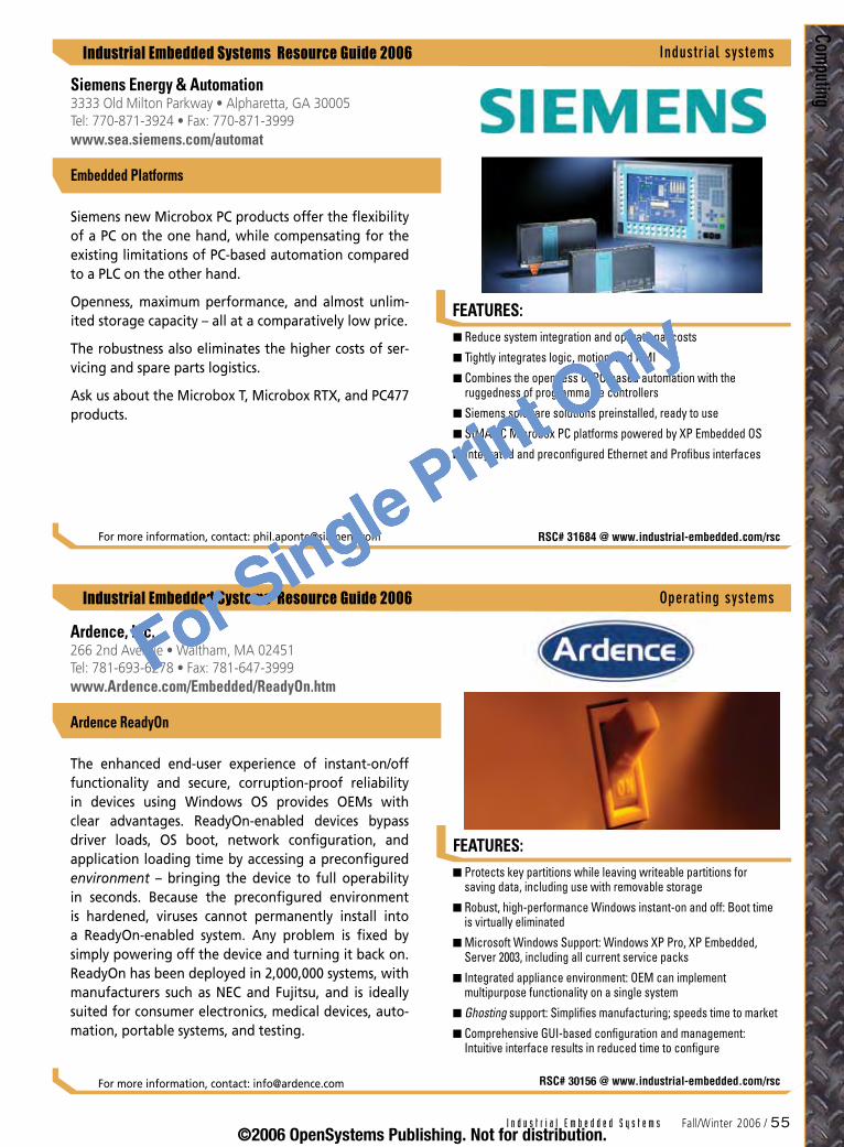
I n d u s t r i a l E m b e d d e d S y s t e m s Fall/Winter 2006 / 55
Industrial Embedded Systems Resource Guide 2006
Industrial Embedded Systems Resource Guide 2006
FEATURES:
Computing
Protects key partitions while leaving writeable partitions for saving data, including use with removable storage
Robust, high-performance Windows instant-on and off: Boot time is virtually eliminated
Microsoft Windows Support: Windows XP Pro, XP Embedded, Server 2003, including all current service packs
Integrated appliance environment: OEM can implement multipurpose functionality on a single system
Ghosting support: Simplifies manufacturing; speeds time to market
Comprehensive GUI-based configuration and management: Intuitive interface results in reduced time to configure
n
n
n
n
n
n
FEATURES:
Ardence, Inc.266 2nd Avenue • Waltham, MA 02451 Tel: 781-693-6278 • Fax: 781-647-3999www.Ardence.com/Embedded/ReadyOn.htm
The enhanced end-user experience of instant-on/off functionality and secure, corruption-proof reliability in devices using Windows OS provides OEMs with clear advantages. ReadyOn-enabled devices bypass driver loads, OS boot, network configuration, and application loading time by accessing a preconfigured environment – bringing the device to full operability in seconds. Because the preconfigured environment is hardened, viruses cannot permanently install into a ReadyOn-enabled system. Any problem is fixed by simply powering off the device and turning it back on. ReadyOn has been deployed in 2,000,000 systems, with manufacturers such as NEC and Fujitsu, and is ideally suited for consumer electronics, medical devices, auto-mation, portable systems, and testing.
For more information, contact: [email protected] RSC# 30156 @ www.industrial-embedded.com/rsc
Operatingsystems
Ardence ReadyOn
Reduce system integration and operational costs
Tightly integrates logic, motion, and HMI
Combines the openness of PC-based automation with the ruggedness of programmable controllers
Siemens software solutions preinstalled, ready to use
SIMATIC Microbox PC platforms powered by XP Embedded OS
Integrated and preconfigured Ethernet and Profibus interfaces
n
n
n
n
n
n
Siemens Energy & Automation3333 Old Milton Parkway • Alpharetta, GA 30005 Tel: 770-871-3924 • Fax: 770-871-3999www.sea.siemens.com/automat
Siemens new Microbox PC products offer the flexibility of a PC on the one hand, while compensating for the existing limitations of PC-based automation compared to a PLC on the other hand.
Openness, maximum performance, and almost unlim-ited storage capacity – all at a comparatively low price.
The robustness also eliminates the higher costs of ser-vicing and spare parts logistics.
Ask us about the Microbox T, Microbox RTX, and PC477 products.
For more information, contact: [email protected] RSC# 31684 @ www.industrial-embedded.com/rsc
Embedded Platforms
Industrialsystems
©2006 OpenSystems Publishing. Not for distribution.
For Single Print Only
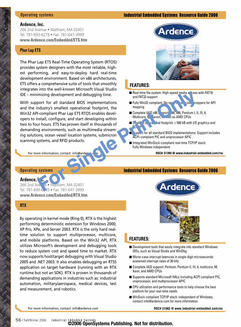
5� / Fall/Winter 2006 I n d u s t r i a l E m b e d d e d S y s t e m s
Industrial Embedded Systems Resource Guide 2006
Industrial Embedded Systems Resource Guide 2006
Com
putin
g
FEATURES:Real-time file system: High-speed media access with FAT16 and FAT32 support
Fully Win32 compliant: No need to use code wrappers for API mapping
Complete IA32 x86 support: 386, 486, Pentium I, II, III, 4, Multicore, M, Xenon, as well as AMD CPUs
Smallest operational footprint: < 500 kB with I/O graphics and TCP/IP
Support for all standard BIOS implementations: Support includes ACPI-compliant PIC and uniprocessor APIC
Integrated WinSock-compliant real-time TCP/IP stack: Fully Windows independent
n
n
n
n
n
n
RSC# 31390 @ www.industrial-embedded.com/rsc
Ardence, Inc.266 2nd Avenue • Waltham, MA 02451Tel: 781-693-6278 • Fax: 781-647-3999www.Ardence.com/Embedded/ETS.htm
Phar Lap ETS
The Phar Lap ETS Real-Time Operating System (RTOS) provides system designers with the most reliable, high-est performing, and easy-to-deploy hard real-time development environment. Based on x86 architectures, ETS offers a comprehensive suite of tools that smoothly integrates into the well-known Microsoft Visual Studio IDE – minimizing development and debugging time.
With support for all standard BIOS implementations and the industry’s smallest operational footprint, the Win32 API-compliant Phar Lap ETS RTOS enables devel-opers to install, configure, and start developing within two to four hours. ETS has proven itself in thousands of demanding environments, such as multimedia stream-ing solutions, ocean vessel location systems, submicron scanning systems, and RFID products.
For more information, contact: [email protected]
Operatingsystems
RSC# 21082 @ www.industrial-embedded.com/rsc
Operatingsystems
Ardence, Inc.266 2nd Avenue • Waltham, MA 02451Tel: 781-693-6345 • Fax: 781-647-3999www.Ardence.com/Embedded/RTX.htm
RTX
By operating in kernel mode (Ring 0), RTX is the highest performing deterministic extension for Windows 2000, XP Pro, XPe, and Server 2003. RTX is the only hard real-time solution to support multiprocessor, multicore, and mobile platforms. Based on the Win32 API, RTX utilizes Microsoft’s development and debugging tools to reduce system cost and speed time to market. RTX now supports host/target debugging with Visual Studio 2005 and .NET 2003. It also enables debugging an RTSS application on target hardware (running with an RTX runtime but not an SDK). RTX is proven in thousands of demanding applications in industries such as: industrial automation, military/aerospace, medical devices, test and measurement, and robotics.
For more information, contact: [email protected]
FEATURES:
Development tools that easily integrate into standard Windows IDEs, such as Visual Studio and WinDbg
Worst-case interrupt latencies in single-digit microseconds: sustained interrupt rates of 30 kHz
Complete IA32 support: Pentium, Pentium II, III, 4, multicore, M, Xeon, and AMD CPUs
Supports standard Microsoft HALs including ACPI compliant PIC, uniprocessor, and multiprocessor APIC
CPU utilization and performance tools to help choose the best platform for your real-time needs
WinSock compliant TCP/IP stack: independent of Windows; contact [email protected] for more information
n
n
n
n
n
n
©2006 OpenSystems Publishing. Not for distribution.
For Single Print Only

FEATURES:
Industrial Embedded Systems Resource Guide 2006
Computing
I n d u s t r i a l E m b e d d e d S y s t e m s Fall/Winter 2006 / 5�
INTEGRITY RTOS
INTEGRITY is a secure, royalty-free RTOS intended for use in embedded systems that require maximum safety, reliability, and security. INTEGRITY represents the most advanced RTOS technology on the market.
INTEGRITY has been successfully deployed in a wide range of applications including industrial control devices certified up to IEC 61508 SIL3, Class II/III FDA approved medical devices, and FAA DO-178B Level A certified avionics systems.
INTEGRITY provides support for time, space, and resource partitioning between applications and has been designed to ensure that an error or failure in one partition cannot prevent an application in another partition from running or disrupt the execution of the kernel. INTEGRITY runs on the most common proces-sors and commercial CPU boards available and offers an extensive suite of middleware that includes file systems, USB, graphics, networking, and security protocols.
The MULTI IDE offers the industry’s most powerful, proven tools and optimizing C/C++ compilers for devel-oping embedded software with maximum reliabil-ity, maximum performance, and minimum code size – allowing you to develop, debug, and optimize code more quickly.
Green Hills also offers a complete platform for industrial safety targeted for industrial product development. Based on INTEGRITY and MULTI, this platform offers unique additional components that provide a com-plete solution for developing safe, reliable, and secure software for industrial control and automation systems while reducing product cost, risk, and time to market. This platform includes a version of INTEGRITY certi-fied to IEC 61508 SIL3, IEC 61508 certificate and report, safety manual, optional confidence from use report for MULTI, defect notification, and optional services includ-ing product certification assistance and training.
This Platform optionally includes other development tools that are integrated with INTEGRITY and MULTI: Telelogic’s Rhapsody UML modeling/simulation and code generation tools, Esterel’s SCADE modeling and IEC 61508 code generation tools, and Vector Software’s VectorCast unit test tools.
Green Hills is the leader in high-performance compilers, software development tools, and RTOSs for developers of embedded systems
INTEGRITY is the only commercial royalty-free RTOS suitable for systems demanding total reliability, safety, and absolute security
INTEGRITY’s secure partitioning architecture supports multiple levels of safety criticality executing at the same time on one processor
INTEGRITY delivers the absolute minimum interrupt latency and complete deterministic execution
INTEGRITY is POSIX conformant to the latest IEEE POSIX standard
INTEGRITY supports advanced middleware for file systems, USB, embedded graphics, networking, wireless and security protocols
MULTI supports code development, optimizing compilation, and extensive debugging features in C/C++ for all major processors
MULTI’s advanced target trace capabilities allow developers to step back in time through executed code to eradicate hard-to-find bugs
MULTI integration: Telelogic Rhapsody UML modeling/simulation and code generation tools
MULTI integration: Esterel Technologies’ SCADE software modeling and IEC 61508 certified code generation for all SIL levels
MULTI integration: Vector Software’s VectorCast software unit level test and code coverage analysis
IEC 61508 certification: INTEGRITY safety manual, SIL3 certificate/report; optional MULTI confidence from use report and services
n
n
n
n
n
n
n
n
n
n
n
n
Operatingsystems
RSC# 22109 @ www.industrial-embedded.com/rscFor more information, contact: [email protected]
Green Hills Software, Inc.30 W. Sola Street • Santa Barbara, CA 93101 Tel: 805-965-6044 • Fax: 805-965-6343www.ghs.com
©2006 OpenSystems Publishing. Not for distribution.
For Single Print Only
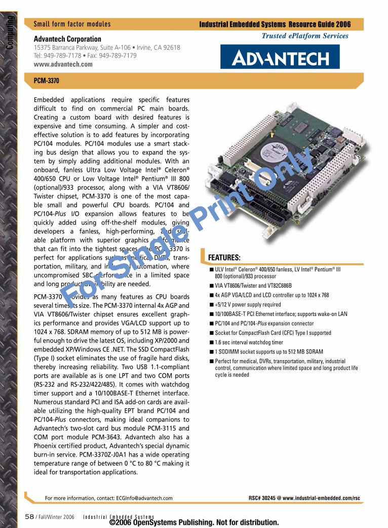
FEATURES:
Industrial Embedded Systems Resource Guide 2006
Com
putin
g
58 / Fall/Winter 2006 I n d u s t r i a l E m b e d d e d S y s t e m s
Smallformfactormodules
PCM-3370
Advantech Corporation15375 Barranca Parkway, Suite A-106 • Irvine, CA 92618 Tel: 949-789-7178 • Fax: 949-789-7179www.advantech.com
RSC# 30245 @ www.industrial-embedded.com/rsc
Embedded applications require specific features difficult to find on commercial PC main boards. Creating a custom board with desired features is expensive and time consuming. A simpler and cost-effective solution is to add features by incorporating PC/104 modules. PC/104 modules use a smart stack-ing bus design that allows you to expand the sys-tem by simply adding additional modules. With an onboard, fanless Ultra Low Voltage Intel® Celeron® 400/650 CPU or Low Voltage Intel® Pentium® III 800 (optional)/933 processor, along with a VIA VT8606/Twister chipset, PCM-3370 is one of the most capa-ble small and powerful CPU boards. PC/104 and PC/104-Plus I/O expansion allows features to be quickly added using off-the-shelf modules, giving developers a fanless, high-performing, and scal-able platform with superior graphics performance that can fit into the tightest spaces. The PCM-3370 is perfect for applications such as medical DVRs, trans-portation, military, and industrial automation, where uncompromised SBC performance in a limited space and long product availability are needed.
PCM-3370 provides as many features as CPU boards several times its size. The PCM-3370 internal 4x AGP and VIA VT8606/Twister chipset ensures excellent graph-ics performance and provides VGA/LCD support up to 1024 x 768. SDRAM memory of up to 512 MB is power-ful enough to drive the latest OS, including XP/2000 and embedded XP/Windows CE .NET. The SSD CompactFlash (Type I) socket eliminates the use of fragile hard disks, thereby increasing reliability. Two USB 1.1-compliant ports are available as is one LPT and two COM ports (RS-232 and RS-232/422/485). It comes with watchdog timer support and a 10/100BASE-T Ethernet interface. Numerous standard PCI and ISA add-on cards are avail-able utilizing the high-quality EPT brand PC/104 and PC/104-Plus connectors, making ideal companions to Advantech’s two-slot card bus module PCM-3115 and COM port module PCM-3643. Advantech also has a Phoenix certified product, Advantech’s special dynamic burn-in service. PCM-3370Z-J0A1 has a wide operating temperature range of between 0 °C to 80 °C making it ideal for transportation applications.
For more information, contact: [email protected]
ULV Intel® Celeron® 400/650 fanless, LV Intel® Pentium® III 800 (optional)/933 processor
VIA VT8606/Twister and VT82C686B
4x AGP VGA/LCD and LCD controller up to 1024 x 768
+5/12 V power supply required
10/100BASE-T PCI Ethernet interface; supports wake-on LAN
PC/104 and PC/104-Plus expansion connector
Socket for CompactFlash Card (CFC) Type I supported
1.6 sec interval watchdog timer
1 SODIMM socket supports up to 512 MB SDRAM
Perfect for medical, DVRs, transportation, military, industrial control, communication where limited space and long product life cycle is needed
n
n
n
n
n
n
n
n
n
n
©2006 OpenSystems Publishing. Not for distribution.
For Single Print Only
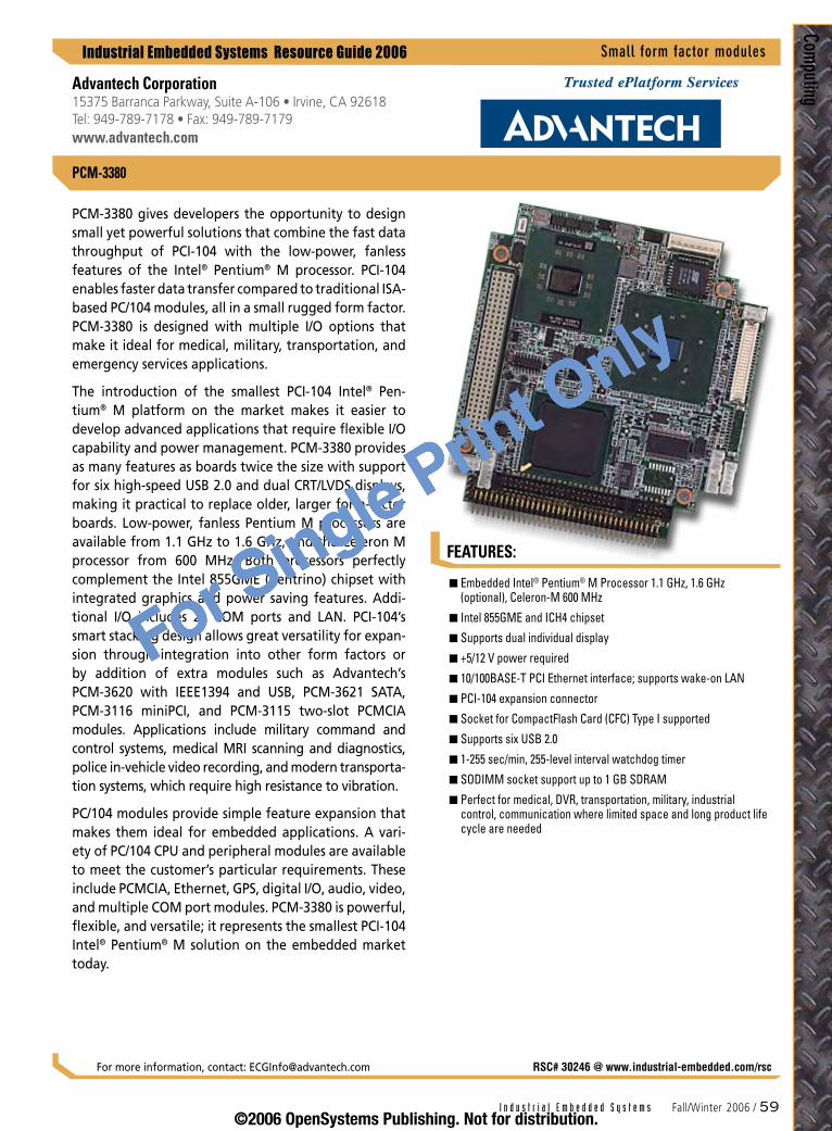
FEATURES:
Industrial Embedded Systems Resource Guide 2006
Computing
I n d u s t r i a l E m b e d d e d S y s t e m s Fall/Winter 2006 / 59
Smallformfactormodules
RSC# 30246 @ www.industrial-embedded.com/rsc
PCM-3380
PCM-3380 gives developers the opportunity to design small yet powerful solutions that combine the fast data throughput of PCI-104 with the low-power, fanless features of the Intel® Pentium® M processor. PCI-104 enables faster data transfer compared to traditional ISA-based PC/104 modules, all in a small rugged form factor. PCM-3380 is designed with multiple I/O options that make it ideal for medical, military, transportation, and emergency services applications.
The introduction of the smallest PCI-104 Intel® Pen-tium® M platform on the market makes it easier to develop advanced applications that require flexible I/O capability and power management. PCM-3380 provides as many features as boards twice the size with support for six high-speed USB 2.0 and dual CRT/LVDS displays, making it practical to replace older, larger form-factor boards. Low-power, fanless Pentium M processors are available from 1.1 GHz to 1.6 GHz, and the Celeron M processor from 600 MHz. Both processors perfectly complement the Intel 855GME (Centrino) chipset with integrated graphics and power saving features. Addi-tional I/O includes 2x COM ports and LAN. PCI-104’s smart stacking design allows great versatility for expan-sion through integration into other form factors or by addition of extra modules such as Advantech’s PCM-3620 with IEEE1394 and USB, PCM-3621 SATA, PCM-3116 miniPCI, and PCM-3115 two-slot PCMCIA modules. Applications include military command and control systems, medical MRI scanning and diagnostics, police in-vehicle video recording, and modern transporta-tion systems, which require high resistance to vibration.
PC/104 modules provide simple feature expansion that makes them ideal for embedded applications. A vari-ety of PC/104 CPU and peripheral modules are available to meet the customer’s particular requirements. These include PCMCIA, Ethernet, GPS, digital I/O, audio, video, and multiple COM port modules. PCM-3380 is powerful, flexible, and versatile; it represents the smallest PCI-104 Intel® Pentium® M solution on the embedded market today.
For more information, contact: [email protected]
Embedded Intel® Pentium® M Processor 1.1 GHz, 1.6 GHz (optional), Celeron-M 600 MHz
Intel 855GME and ICH4 chipset
Supports dual individual display
+5/12 V power required
10/100BASE-T PCI Ethernet interface; supports wake-on LAN
PCI-104 expansion connector
Socket for CompactFlash Card (CFC) Type I supported
Supports six USB 2.0
1-255 sec/min, 255-level interval watchdog timer
SODIMM socket support up to 1 GB SDRAM
Perfect for medical, DVR, transportation, military, industrial control, communication where limited space and long product life cycle are needed
n
n
n
n
n
n
n
n
n
n
n
Advantech Corporation15375 Barranca Parkway, Suite A-106 • Irvine, CA 92618 Tel: 949-789-7178 • Fax: 949-789-7179www.advantech.com
©2006 OpenSystems Publishing. Not for distribution.
For Single Print Only
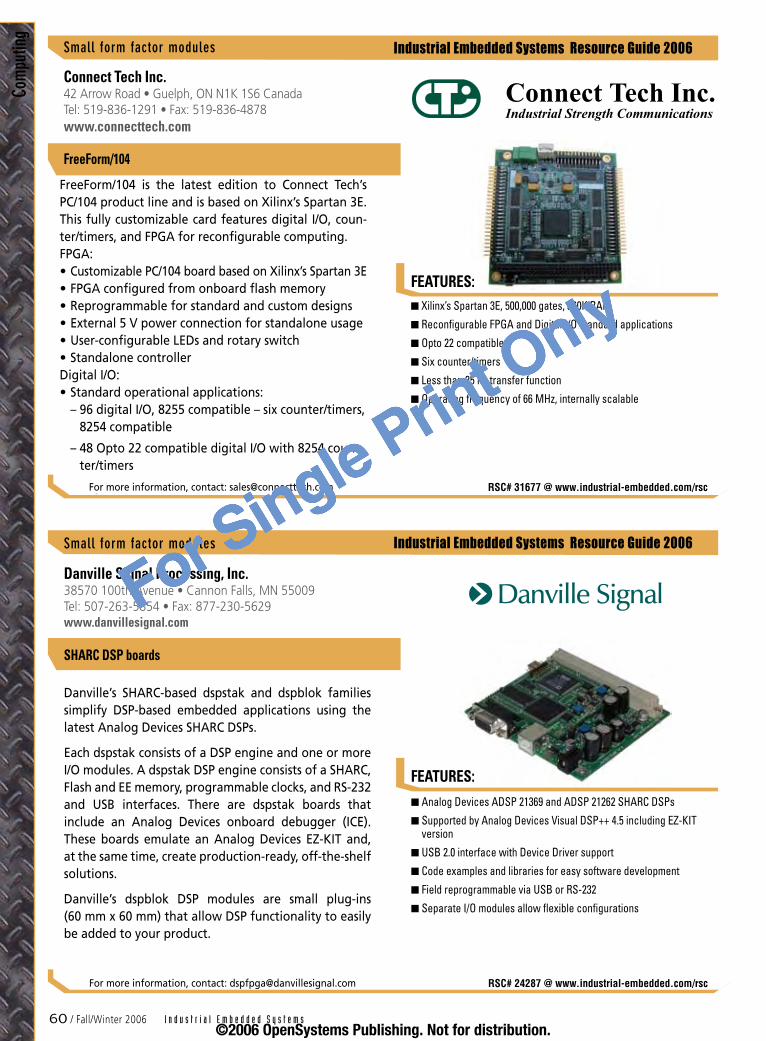
�0 / Fall/Winter 2006 I n d u s t r i a l E m b e d d e d S y s t e m s
Industrial Embedded Systems Resource Guide 2006
FEATURES:
FEATURES:
Industrial Embedded Systems Resource Guide 2006
Com
putin
g
Analog Devices ADSP 21369 and ADSP 21262 SHARC DSPs
Supported by Analog Devices Visual DSP++ 4.5 including EZ-KIT version
USB 2.0 interface with Device Driver support
Code examples and libraries for easy software development
Field reprogrammable via USB or RS-232
Separate I/O modules allow flexible configurations
n
n
n
n
n
n
Danville Signal Processing, Inc.38570 100th Avenue • Cannon Falls, MN 55009 Tel: 507-263-5854 • Fax: 877-230-5629www.danvillesignal.com
Danville’s SHARC-based dspstak and dspblok families simplify DSP-based embedded applications using the latest Analog Devices SHARC DSPs.
Each dspstak consists of a DSP engine and one or more I/O modules. A dspstak DSP engine consists of a SHARC, Flash and EE memory, programmable clocks, and RS-232 and USB interfaces. There are dspstak boards that include an Analog Devices onboard debugger (ICE). These boards emulate an Analog Devices EZ-KIT and, at the same time, create production-ready, off-the-shelf solutions.
Danville’s dspblok DSP modules are small plug-ins (60 mm x 60 mm) that allow DSP functionality to easily be added to your product.
For more information, contact: [email protected] RSC# 24287 @ www.industrial-embedded.com/rsc
Smallformfactormodules
SHARC DSP boards
Xilinx’s Spartan 3E, 500,000 gates, 360K RAM
Reconfigurable FPGA and Digital I/O standard applications
Opto 22 compatible
Six counter/timers
Less than 25 ns transfer function
Operating frequency of 66 MHz, internally scalable
n
n
n
n
n
n
Connect Tech Inc.42 Arrow Road • Guelph, ON N1K 1S6 CanadaTel: 519-836-1291 • Fax: 519-836-4878www.connecttech.com
FreeForm/104 is the latest edition to Connect Tech’s PC/104 product line and is based on Xilinx’s Spartan 3E. This fully customizable card features digital I/O, coun-ter/timers, and FPGA for reconfigurable computing. FPGA:
Customizable PC/104 board based on Xilinx’s Spartan 3EFPGA configured from onboard flash memoryReprogrammable for standard and custom designsExternal 5 V power connection for standalone usageUser-configurable LEDs and rotary switchStandalone controller
Digital I/O: Standard operational applications: – 96 digital I/O, 8255 compatible – six counter/timers,
8254 compatible
– 48 Opto 22 compatible digital I/O with 8254 coun-ter/timers
••••••
•
For more information, contact: [email protected] RSC# 31677 @ www.industrial-embedded.com/rsc
Connect Tech Inc.Industrial Strength Communications
Smallformfactormodules
FreeForm/104
©2006 OpenSystems Publishing. Not for distribution.
For Single Print Only
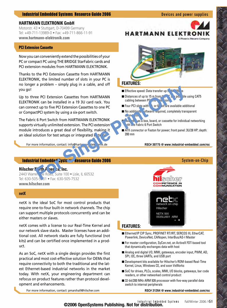
I n d u s t r i a l E m b e d d e d S y s t e m s Fall/Winter 2006 / �1
Industrial Embedded Systems Resource Guide 2006
Industrial Embedded Systems Resource Guide 2006
FEATURES:
Computing
Ethernet/IP CIP Sync, PROFINET RT/IRT, SERCOS III, EtherCAT, Powerlink, DeviceNet, CANopen, InterBus/AS-I Master
For master configuration, SyCon.net, an ActiveX FDT-based tool that dynamically exchanges data with host
Analog and digital I/O, MMI, gateways, encoder input, PWM, AD, SPI, I2C, three UARTs, and USB port
Development kits available for Hilscher’s ROM-based Real-Time Kernel, Linux, Windows CE, and soon VxWorks
SoC for drives, PLCs, scales, MMI, I/O blocks, gateways, bar code readers, or other networked control product
32-bit/200 MHz ARM 926 processor with five-way parallel data switch to internal peripherals
n
n
n
n
n
n
Hilscher North America, Inc.2443 Warrenville Road, Suite 100 • Lisle, IL 60532 Tel: 630-505-5301 • Fax: 630-505-7532www.hilscher.com
netX is the ideal SoC for most control products that require one-to-four built-in network channels. The chip can support multiple protocols concurrently and can be either masters or slaves.
netX comes with a license to our Real-Time Kernel and our network slave stacks. Master licenses have an addi-tional cost. All network stacks are fully functional (not kits) and can be certified once implemented in a prod-uct.
As an SoC, netX with a single design provides the first practical and most cost-effective solution for OEMs that require connectivity to both the traditional and the lat-est Ethernet-based industrial networks in the market today. With netX, your engineering department can refocus on product features rather than protocol devel-opment and enhancements.
For more information, contact: [email protected] RSC# 31264 @ www.industrial-embedded.com/rsc
FEATURES:
netX
System-on-Chip
RSC# 30775 @ www.industrial-embedded.com/rsc
Effective speed: Data transfer up to 440 MBps
Distances of up to 15 m from the PC are possible using CAT5 cabling between PC and extension
Four PCI slots with 32- or 64-bit are available additional
No additional software required, completely transparent connection
Available as a box, board, or cassette for individual networking with the Fabric 6 Port Switch
ATX connector or Faston for power; front panel: 3U/28 HP; depth: 200 mm
n
n
n
n
n
n
HARTMANN ELEKTRONIK GmbHMotorstr. 43 • Stuttgart, D-70499 GermanyTel: +49-711-13989-0 • Fax: +49-711-866-11-91www.hartmann-elektronik.com
PCI Extension Cassette
Now you can conveniently extend the possibilities of your PC or compact PC using THE BRIDGE StarFabric cards and PCI extension modules from HARTMANN ELEKTRONIK.
Thanks to the PCI Extension Cassette from HARTMANN ELEKTRONIK, the limited number of slots in your PC is no longer a problem – simply plug in a cable, and off you go!
Up to three PCI Extension Cassettes from HARTMANN ELEKTRONIK can be installed in a 19 3U card rack. You can connect up to five PCI Extension Cassettes to one PC or CompactPCI system by using a six-port switch.
The Fabric 6 Port Switch from HARTMANN ELEKTRONIK supports virtually unlimited extension. The PCI extension module introduces a great deal of flexibility, making it an ideal solution for test setups or integrated systems.
For more information, contact: [email protected]
Devicesandpowersupplies
PCI Extension Cassette
©2006 OpenSystems Publishing. Not for distribution.
For Single Print Only

�2 / Fall/Winter 2006 I n d u s t r i a l E m b e d d e d S y s t e m s
Industrial Embedded Systems Resource Guide 2006
FEATURES:
Netw
orkin
g
FEATURES:
Industrial Embedded Systems Resource Guide 2006
Created around a ColdFire CPU featuring 16 MB SDRAM, 2 MB or 4 MB flash, quad UARTs, and a Linux core
Numerous application modes and protocols available, including Point-to-Point Protocol (PPP) and Raw TCP
Built on the uClinux embedded operating system, enabling the development of customized software
Configuration over a serial interface or using Telnet with subsystem administration capabilities with HTTP
Independent configuration for 2, 4, 8, or 16 RS-232 or software-selectable RS-232/422/485 ports
Real data transfer speeds of up to 460.8 kbps per port
n
n
n
n
n
n
Connect Tech Inc.42 Arrow Road • Guelph, ON N1K 1S6 CanadaTel: 519-836-1291 • Fax: 519-836-4878www.connecttech.com
Network-enable serial devices with Blue Heat/Net. With 2, 4, 8, or 16 ports of RS-232/422/485 connectiv-ity, you can locate COM ports exactly where you want them without the need for a physical PC connection. Remotely control serial peripherals from any terminal connected to the Ethernet LAN or Internet.
Fully customizable, each port can be individually config-ured and controlled via serial interface, remote Telnet, or HTTP. Achieve data speeds of 460.8 kbps/port with autosensing 10BASE-T and 100BASE-TX LAN.
Based on the uClinux embedded operating system, Blue Heat/Net offers programmers a familiar Linux API. Open source development tools are also available via our Software Development Kit. Create customized pro-tocols and download to onboard flash memory.
For more information, contact: [email protected] RSC# 22722 @ www.industrial-embedded.com/rsc
Connect Tech Inc.Industrial Strength Communications
Wired
Blue Heat/Net
Ethernet/IP (with CIP Sync), PROFINET (RT/IRT), SERCOS III, EtherCAT, ETHERNET Powerlink, MB/TCP
DeviceNet, CAN, CANopen, InterBus Master, AS-I Master
For master configuration, SyCon.net, an ActiveX FDT-based tool that dynamically exchanges data with host
Interface to host can be via dual-port memory, SPI Bus, serial, USB
Standard dual-port driver model
Available as a chip or on a daughter board (Com-C) interchangeable modules
n
n
n
n
n
n
Hilscher North America, Inc.2443 Warrenville Road, Suite 100 • Lisle, IL 60532 Tel: 630-505-5301 • Fax: 630-505-7532www.hilscher.com
netX is a network coprocessor for most control prod-ucts that need one-to-four network channels. netX can interface to a host via dual-port memory or serial and can support multiple protocols concurrently that can be either masters or slaves.
netX comes with a license to our Real-Time Kernel and our slave network stacks. Master licenses are an addi-tional cost. All network stacks are fully functional and can be certified once implemented in a product.
netX with a single design provides the first practical and cost-effective solution for OEMs that require con-nectivity to both the traditional and the latest Ethernet-based industrial networks. With netX, your engineering department can refocus on product features rather then protocol development and enhancements.
For more information, contact: [email protected] RSC# 31264 @ www.industrial-embedded.com/rsc
Wired
netX
©2006 OpenSystems Publishing. Not for distribution.
For Single Print Only
I n d u s t r i a l E m b e d d e d S y s t e m s Fall/Winter 2006 / �3
Industrial Embedded Systems Resource Guide 2006
Industrial Embedded Systems Resource Guide 2006
Networking
FEATURES:
FEATURES:Integral LION Battery (1.1 AH), built-in charger, low power consumption, charged from any 5 Vdc power source
Supports bidirectional RS-232 signaling at a maximum rate of 232.4 kbps; supports RX, TX, RTS, and CTS
External antenna (SMA jack and ANT) to maximize range
Onboard jumpers to switch from DTE/DCE and disable flow control
Compatible with all clients running under Windows, Apple, PocketPC, and other platforms
24 to 30 hours of continuous connection and transferring of data on a single charge
n
n
n
n
n
n
Grid Connect, Inc.1841 Centre Point Circle, Suite 143 • Naperville, IL 60563 Tel: 630-245-1445 • Fax: 630-245-1717www.gridconnect.com
Now you can get a totally wireless and portable Class 1 (330 feet) Bluetooth serial adapter with the Bluetooth BluePort XP. You can create wireless connections any-where, anytime. Just attach the BluePort XP to a 9-pin RS-232/EIA232 port, turn it on, and be connected.
With the integrated Power Pack, you can get up to 24 hours of continuous connection and transferring of data on a single charge; it can run for hundreds of hours in standby mode.
This unit can be paired/linked with other Bluetooth devices. As a Class 1 Bluetooth device, the BluePort XP’s transmit range can be up to 330 feet (100 m) depend-ing on environmental conditions.
For more information, contact: [email protected] RSC# 31680 @ www.industrial-embedded.com/rsc
Wireless
BluePort XP
EtherNet/IP server generic device operation
High-speed TTL serial interface with up to 230 kbps throughput
Small footprint 1.445" (36.703 mm) x 0.75" (19.05 mm) x 0.735" (18.669 mm)
802.3-compliant 10/100 Mb network interface
Extended operating range (-40 °C to 185 °C)
Modbus RTU slave host communications
n
n
n
n
n
n
Real Time Automation2825 N. Mayfair Road #11 • Wauwatosa, WI 53222 Tel: 414-453-5100 • Fax: 414-453-5125www.rtaautomation.com
Ethernet/IP communications in weeks not months.
EtherNet/IP in an RJ-45 connector.
Deliver Ethernet to your customers’ today, not tomorrow.
And it’s only the size of a pair of dice.
EtherNet/IP PCB Network Enabler
Additional features:
High-performance NS7520 32-bit 55 MIPS ARM7TDMI RISC core
Optional Modbus/TCP communications
www.Get-EtherNet-Enabled.com
•
•
For more information, contact: [email protected] RSC# 31683 @ www.industrial-embedded.com/rsc
EtherNet/IP
Wired
©2006 OpenSystems Publishing. Not for distribution.
For Single Print Only
�� / Fall/Winter 2006 I n d u s t r i a l E m b e d d e d S y s t e m s
Industrial Embedded Systems Resource Guide 2006
Netw
orkin
g
FEATURES:
Industrial Embedded Systems Resource Guide 2006
Data reservation provides ability to achieve deterministic control and dedicated data speed for critical clients
Rugged metal housing offers protection against dust, water, and foreign bodies with IP 65 protection
Supports active antenna diversity to avoid wireless dead zones, and IEEE 802.11 a/b/g compliant
Redundant power supply and Power-over-Ethernet (IEEE 802.11af) compliant
Stores configuration data using the C-plug (memory module), reducing maintenance costs
Wi-Fi Protected Access (WPA) and Advanced Encryption Standard (AES) with 128-bit encryptions
n
n
n
n
n
n
Siemens Energy & Automation5300 Triangle Parkway • Norcross, GA 30092 Tel: 770-871-3878 • Fax: 770-871-3999www.sea.siemens.com/scalancewireless
Scalance W is a line of industrial-grade wireless commu-nication products that offer superior IP 65 protection against dust, water, vibration, and other environmental effects, enabling roaming between indoor networks and outdoor communication devices such as VoIP phones, computers, wireless work tablets, PDAs, and video surveillance cameras to name a few.
The product line includes single and dual access points with an extremely high degree of protection from unau-thorized access, Wi-Fi Protected Access (WPA) security, and Advanced Encryption Standard (AES) with 128-bit encryptions – all features that guarantee high security and increased design flexibility with a patented Quality of Service (QoS) solution that gives preference to traffic from critical clients.
For more information, contact: [email protected] RSC# 31685 @ www.industrial-embedded.com/rsc
FEATURES:
Scalance Wireless
Wireless
®
200 MHz 60x/MPX processor bus – dual CPU support
Quad GbE with interrupt moderation and H/W checksum support
Two 4-lane PCI Express ports
64-bit 133 MHz PCI-X interface
Designed for 200 MHz operation with only eight PCB layers
DDR2 memory controller – up to 50 percent memory power savings compared to DDR
n
n
n
n
n
n
Tundra Semiconductor603 March Road • Ottawa, ON K2K 2M5 CanadaTel: 613-592-0714 • Fax: 613-592-1320www.tundra.com
The Tsi110 is a high-performance host bridge designed for use with Freescale and IBM PowerPC processors. Ideal for power- and cost-sensitive applications, the Tsi110 integrates several communications peripherals – includ-ing two 4-lane PCI Express ports, four Gigabit Ethernet ports, and one PCI-X port. This high level of integra-tion offers system designers numerous options for I/O connectivity and reduces external component count. The Tsi110 offers the selection of PCI/PCI-X modes, an integrated clock generator, DDR2 memory support, and the ability to configure the device as a PCI host/agent, enabling it to be used in a range of applications.
The Tsi110 is software compatible with the Tsi109™ and Tsi108™, allowing software reuse and accelerating development cycles.
For more information, contact: [email protected] RSC# 31127 @ www.industrial-embedded.com/rsc
Tundra Tsi110™
Wireless
©2006 OpenSystems Publishing. Not for distribution.
For Single Print Only

I n d u s t r i a l E m b e d d e d S y s t e m s Fall/Winter 2006 / �5
Industrial Embedded Systems Resource Guide 2006
Industrial Embedded Systems Resource Guide 2006
Storage
FEATURES:
Eliminates data loss or corruption with pioneering transaction-point technology
Reduces warranty costs due to file system corruption and user complaints
Enhances device performance with fast boot times in under one second, regardless of disk volume
Ensures secure data portability with Windows XP driver for Reliance-formatted removable media cards
Works with virtually any block device driver, including those for flash memory, Disk-On-Chip, SD/MMC, and USB
Supports VxWorks, Nucleus, Windows CE out of the box; RTOS porting kit for other 32-bit OS of your choice
n
n
n
n
n
n
Datalight21520 30th Drive S.E. • Bothell, WA 98021 Tel: 425-951-8086 • Fax: 425-951-8094www.datalight.com
Datalight Reliance is the pioneering transactional file system, specifically designed for use with embedded devices that operate in environments where power loss may occur. Reliance works with any storage media – including flash memory, RAM, hard disk, USB mass stor-age, and MMSDC – and any 32-bit operating system.
Reliance keeps track of both the file system’s metadata and user data, updating information to memory at user-settable transaction points. Its transaction-based approach offers the user an always consistent file sys-tem. At the time of a transaction point, new data is written to a new area on the storage media. If a power interruption occurs, the file system will still have the last saved data available.
For more information, contact: [email protected]
Disk Cache (optional)
Reliance Core
Block DeviceInterface
OS ServicesFile System Interface
Embedded Application
Real-time Operating System
DatalightRelianceTM
BufferManager
Real-timeOperating
SystemPartition Manager (optional)
Block Device Driver
OEM Hardware Platform
RSC# 15963 @ www.industrial-embedded.com/rsc
Software for Trustworthy Data on Successful Devices
Hardware
FEATURES:
Reliance™ Reliable File System for Rapid Development of Reliable Products
Up to 250 MHz maximum global operating frequency
Configurable I/Os: LVTTL, LVCMOS, HSTL, SSTL, LVDS, LVPECL, RSDS, PCI, PCI-X, XOSC, and double data rate
PCI Express PHY (1-8 lanes)
USB 2.0 OTG PHY
Gate capacity from 20k to 1.8M and memory capacity up to 806 kb
USB 2.0 T&MT board evaluation kit
n
n
n
n
n
n
ChipX, Inc.2323 Owen Street • Santa Clara, CA 95054 Tel: 408-988-2445 • Fax: 408-988-2449www.chipx.com/gift
ChipX, Inc. is a leader in the development of Structured ASIC products and technology. Using our patented tech-nology, ChipX provides the widest range of Structured ASICs in the market today, backed by a track record of more than 1,500 Structured ASIC designs completed and in production. ChipX Structured ASICs offer high speed and low power, without the long manufacturing times or risks associated with traditional ASICs. Each of our five Structured ASIC families supports the requirements of industrial, consumer, medical, or military/aerospace (ITAR compliant) applications. With slices covering gates, memory, and hard IP cells such as PCI Express, USB 2.0 OTG, and DDR/DDRII PHY, ChipX Structured ASICs are ideal for migrating quickly from prototypes to volume production.
For more information, contact: [email protected] RSC# 23624 @ www.industrial-embedded.com/rsc
Structured ASICs
Hardware
©2006 OpenSystems Publishing. Not for distribution.
For Single Print Only
�� / Fall/Winter 2006 I n d u s t r i a l E m b e d d e d S y s t e m s
Industrial Embedded Systems Resource Guide 2006
FEATURES:
Stor
age
FEATURES:
Industrial Embedded Systems Resource Guide 2006
RSC# 30218 @ www.industrial-embedded.com/rsc
Hardware
Nylon or aluminum (mating screw and hex nut available for either material)
Length: 0.600"; diameter 3/16"; round and hexagon profiles
3/16" long, 4-40 male thread on one end
1/4" deep, 4-40 internal thread depth
Precision manufactured for perfect fit
Availability immediate – in stock
n
n
n
n
n
n
Male-female stacking spacers from RAF Electronic Hard-ware help overcome space limitations that may occur when PC/104 or PC/104-Plus bus drives are installed. With this approach, standalone module stacks are used like ultra-compact bus boards, but without needing backplanes or bird cages. Module boards are spaced exactly 0.6" apart using RAF precision-made nylon or aluminum male-female spacers, to build structurally secure standalone module stacks.
RAF stacking spacers allow PC/104 and PC/104-Plus embedded system designers to employ application- specific module stacks for their products that are easily and securely assembled. The RAF hardware can be used with any of more than 100 different PC/104 ultra- compact bus board modules produced by manufac- turers today.
For more information, contact: [email protected]
Male-Female Stacking
RAF Electronic Hardware95 Silvermine Road • Seymour, CT 06483 Tel: 203-888-2133 • Fax: 203-888-9860www.rafhdwe.com
Software for Trustworthy Data on Successful Devices
Fault tolerance even during unexpected power failures
Patented bad block management and wear leveling reduces warranty costs and user complaints
Multithreaded architecture and support for NAND controllers enhances device performance
Reduces time to market with drivers for more than 100 state-of-the-art NOR and NAND flash parts
Ensures accurate data management with support for multiple block sizes and multiple partitions
Use varying types of flash (NAND, NOR, and MLC NOR, that is, Sibley) the same device
n
n
n
n
n
n
Datalight21520 30th Drive S.E. • Bothell, WA 98021 Tel: 425-951-8086 • Fax: 425-951-8094www.datalight.com
FlashFX Pro is a high-performance, multithreaded flash media manager for devices using resident flash memory. In addition to standard flash media manager features such as bad block management, wear level-ing, and preserving data, FlashFX Pro uniquely supports an extensive library of innovative flash technologies, speeding integration and time to market for device manufacturers.
FlashFX Pro includes Flash Interface Modules (FIMs) in the source code, which interface to different flash ven-dor hardware. These prewritten FIMs allow the integra-tion of a new flash part into the design to be a seamless effort. More than 100 state-of-the-art NAND and NOR parts are supported with the FIMs that are included in FlashFX Pro.
For more information, contact: [email protected] RSC# 31678 @ www.industrial-embedded.com/rsc
Software
FlashFX Pro™ High Performance for Rapid Development of Reliable Products
©2006 OpenSystems Publishing. Not for distribution.
For Single Print Only
RSC# 67 @ www.industr ial-embedded.com/rsc©2006 OpenSystems Publishing. Not for distribution.
For Single Print Only

RSC# 6� @ www.industr ial-embedded.com/rsc©2006 OpenSystems Publishing. Not for distribution.
For Single Print Only