2006-7_remote gas strategies ..of natural gas hydrates_aug 06
DESCRIPTION
gasTRANSCRIPT

PEP Review 2006-7 REMOTE GAS STRATEGIES ONSITE STORAGE OF NATURAL GAS HYDRATES
By Ron Smith
August 2006
ABSTRACT
Natural gas is rapidly becoming a strategic fuel of geopolitical importance. Gas has grown from a marginal fuel, consumed in regionally disconnected markets, to a fuel that is now being transported from remote sites across great distances. Increasingly, natural gas is the fuel of choice for consumers seeking its relatively low environmental impact, especially for electric power generation. For example, the International Energy Agency predicts that the electric power sector will account for 60% of the increase in future gas demand. As a result, world gas consumption is projected to more than double over the next three decades, rising from 23% to 28% of world total primary energy demand by 2030, and surpassing coal as the world’s number two energy source. Eventually, gas may even overtake oil’s number one position as a primary energy source in many large industrialized economies.
The growing importance of natural gas supply from remote regions to the world’s modern economies will force new thinking about natural gas based energy supply and energy security. This thinking will need to be backed with technology improvements, reduced logistics costs, and international co-operation to meet global long term demand for natural gas.
In this review, we discuss the potential use of natural gas hydrates as an energy resource, followed by an evaluation of the potential for use of a 780 mm scf/yr capacity natural gas hydrates storage facility to supply distributed power generation and small scale chemical manufacturing plants with natural gas supply during short term pipeline supply disruptions. Results from this study show that the technology and conceptual economics for the potential use of manufactured natural gas hydrates as a new storage option for reliable natural gas supply is competitively viable in places where natural gas pipeline infrastructure exists for distributed consumption.

R eview No. 2006-7
R E MOT E G A S S T R A T E G IE S � ONS IT E S T OR A G E OF �
NA T UR A L G A S HY DR A T E S
by R on S mith
S eptember 2006
A private report by the
P R OC E S S E C ONOMIC S P R OG R A M
SR I Menlo P ark, C alifornia 94025

© SRI Consulting iii PEP Review 2006-7
CONTENTS
INTRODUCTION ................................................................................................................ 2
Recent Natural Gas Hydrate Research and Development Efforts............................. 2
NATURAL GAS HYDRATES OVERVIEW ................................................................. 3
PROCESS CONSIDERATIONS USING HYDRATES ............................................... 6
Process Considerations Using Manufactured (Man-Made) Natural Gas Hydrates ... 8
Alternative Processes for Production of Natural Gas Hydrates ........................... 9
Agitated Reactor................................................................................................... 9
Fluidized Bed Granulator...................................................................................... 10
Offshore Hydrate Slurry Process.......................................................................... 10
Surfactant Addition to a Non-Agitated Reactor .................................................... 12
ENHANCED PROCESS FOR NATURAL GAS HYDRATE STORAGE .................... 12
PROCESS DESCRIPTION ........................................................................................ 13
Hydrate Formation...................................................................................................... 15
Hydrate Storage ......................................................................................................... 16
Hydrate Decomposition .............................................................................................. 16
PROCESS DISCUSSION........................................................................................... 17
COST ESTIMATES .................................................................................................... 19
Capital Cost ................................................................................................................ 19
Production Cost .......................................................................................................... 19
SUMMARY ................................................................................................................. 20
CONCLUSIONS ......................................................................................................... 21
CITED REFERENCES ....................................................................................................... 26
PATENT ASSIGNEES ....................................................................................................... 28

© SRI Consulting iv PEP Review 2006-7
ILLUSTRATIONS
1 Hydrate Storage Process ...................................................................................... 14
2 Hydrate Reactor .................................................................................................... 18
3 Comparison of Hydrate User Costs With Conventional Storage Systems ........... 20

© SRI Consulting v PEP Review 2006-7
TABLES
1 Natural Gas Hydrate Storage Design Basis and Assumptions............................................................................. 15
2 Natural Gas Hydrate Storage Major Equipment ................................................................................................... 22
3 Natural Gas Hydrate Storage Total Capital Investment........................................................................................ 23
4 Natural Gas Hydrate Storage Production Costs ................................................................................................... 24

© SRI Consulting PEP Review 2006-7 2
•
•
•
•
INTRODUCTION
The history of natural gas hydrates has evolved over three major development periods:
1810 to 1934 - Confirmed discovery and scientific curiosity.
1934 to present – Investigations aimed at mitigating the inadvertent formation of natural gas hydrates under man-made conditions, as such hydrates are a hindrance to the commercial pipeline-based natural gas industry.
1960 to present - Discovery and cataloguing natural formations of natural gas reserves as hydrates in both deep oceans and permafrost regions of the world as well as extraterrestrial environments, for consideration as a source of fuel.
The presence of natural gas hydrates were first anecdotally documented by Sir Humphrey Davy with brief comments during a lecture to the British Royal Society on chlorine (then called oxymuriatic gas) in 1810. Over the following 125 years, researchers in the field had two major goals; namely to identify all of the chemical compounds which formed hydrates, and to quantitatively describe the composition and structure of these compounds.
The early period of hydrate research determined the existence of methane, ethane, and propane hydrates, but the formation of butane hydrates were not discovered and measured until 1954. It gradually became clear that the newer clathrate hydrates distinguished themselves by being both non-stoichiometric and crystalline, while at the same time different from normal hexagonal ice.
Recent Natural Gas Hydrate Research and Development Efforts
Since 1970, hydrate research had been focused mostly to address natural gas processing problems in unusual environments such as the North Slope of Alaska, in Siberia, the North Sea, and in deep-ocean drilling. The trend to mitigate hydrate formation in deepwater pipelines appears to be directed at multiphase pipeline transmission. In the 1980s, comprehensive measurements were made of the aqueous phase methanol and glycol concentrations needed to inhibit formation of hydrates in both the gas and the condensed hydrocarbon phases. Recently, two additional techniques have arisen to replace the use of methanol in dealing with hydrate formations. The anti-agglomeration approach uses a surfactant to emulsify the water phase internal to the liquid hydrocarbon phase. A second method inhibits the kinetics of hydrate formation, by preventing crystal growth.
Natural gas hydrate formation is still a substantial problem in deepwater hydrocarbon production and pipelines in the North Sea and the Gulf of Mexico. Pipelines that transport condensed phase hydrocarbons (such as gas condensate or crude oil) have only limited options for removing hydrates once solid hydrate plugs have formed, and there are four safety aspects associated with their removal, as described below:
When hydrates plug pipelines, they are usually removed through depressurization, sometimes depressurizing only one side of the plug. The plugs dissociate first at the pipe wall, thus becoming a projectile in a pipeline with substantial fluid momentum relative to the gas phase. There have been incidents in which hydrate projectiles erupted from pipeline elbows, causing loss of life and substantial asset damage. Where possible, depressurization from both sides of a plug is recommended.

© SRI Consulting PEP Review 2006-7 3
•
•
•
In drilling through underground or under sea bed hydrates and in drilling normal land-based wells, hydrates have jeopardized the safety of drillers, necessitating the use of special drilling precautions and drilling muds.
Hydrates have been associated with significant movement of the earth in deepwater ocean environments. Concerns have been expressed about the effect of hydrates on foundations of platforms and pipelines, as well as offshore drilling operations.
Hydrates have also been the source of speculation on long range climate change and safety with regard to the greenhouse effect. Recently, the indicated uncertainty in the best climate change models show a greater than usual amount of methane release is possible from sub surface hydrates due to rising global temperatures.
Speculation about the role of hydrates in potential offshore operations is beyond the scope of this review; however, we do note that the stability of methane hydrates on the sea floor has a whole raft of implications. First, as discussed below, the hydrates constitute a huge potential source of energy. Second, natural disturbances (or man-made ones, if we exploit gas hydrates and are not careful) might suddenly destabilize sea floor methane hydrates, triggering sub-marine landslides and huge releases of methane. Methane is a highly ranked greenhouse gas, and large scale methane releases may explain sudden episodes of climatic warming in the geologic past. Methane would oxidize fairly quickly in the atmosphere but could cause sufficient warming that linked mechanisms (for example release of carbon dioxide from decaying biomass) could keep the global temperatures elevated.
NATURAL GAS HYDRATES OVERVIEW
In general, natural gas hydrates are non-stoichiometric crystalline compounds that belong to the inclusion group of solids called clathrates, named after the Latin word clathratus which means to encage. All hydrate structures have repetitive spherical “cages” of hydrogen-bonded water molecules. Each cage contains at most one guest molecule, held within the cage by dispersion forces. The common name “natural gas hydrates” may be used interchangeability with the technical designation, “clathrate hydrates” of natural gas. In gas hydrates, a guest molecule such as the methane of natural gas is contained within the cage-like crystalline structure of the host water molecule. Natural gas hydrates can be considered to be modified ice structures enclosing methane and other hydrocarbons, but they can have melting temperatures well above that of normal ice.
The accuracy of hydrate composition measurements is substantially decreased by the difficulty of removing all associated water from the solid hydrate mass. Hydrate formations often occlude water within solid structures in a metastable configuration, thereby confounding composition measurements of gas obtained by dissociation. Measurements of mixed guest hydrate compositions are also confounded by the concentration of heavy components in the hydrate phase. Thus unless an associated gas reservoir is large, preferential hydration may result in a variable gas composition and an inhomogeneous hydrate phase.
The difficulties in hydrate phase measurement, and the availability of a sound molecular based hydrate model, have caused scientists to begin to predict, rather than measure, hydrate phase properties. Reliance on hydrate phase predictions and avoidance of hydrate composition measurements are thus still significant problems yet to be solved in modern hydrate technology.
Naturally occurring hydrates, containing mostly methane, exist in vast quantities within and below the permafrost zone and in sub-sea sediments, and these are now being looked upon as a future energy source. Natural gas hydrates form when water molecules attach themselves through hydrogen bonding and form cage structures that can be occupied by a single gaseous or

© SRI Consulting PEP Review 2006-7 4
•
•
•
volatile liquid molecule. The presence of gas or volatile liquid inside the water network thermodynamically stabilizes the structure through physical bonding via weak van der Waals forces. Large masses of methane hydrate, also known as “yellow ice”, have been photographed on the ocean floor. Chunks of these masses occasionally break loose and float to the surface where they become unstable and effervesce as they decompose.
During the late 1940s and early 1950s, two decades of x-ray hydrate crystal diffraction studies at the University of Bonn were summarized by the determination of two crystalline structures, dubbed sI and sII, for natural gas hydrates. Structure sI is cubic. A dodecahedral cage is centered at the corners of a unit cell with a rotated dodecahedron in the center of the cell. The dodecahedra are linked by 14-faced cages that consist of hexagonal ends and 12 pentagons. Structure sII is also cubic, with 16-faced cages consisting of 12 pentagons and 4 hexagons arranged tetrahedrally. A third hydrate structure, named sH, was discovered in 1987. The H (for hexagonal) structure consists of three cages: dodecahedra; cages with 4, 5, and 6-sided faces; and “barrels” consisting of 12 pentagonal and 8 hexagonal faces. The “barrels” can hold large hydrocarbon molecules. They are surrounded by a hexagonal net of 4, 5, and 6 cages, and layers of these cages alternate with hexagonal nets of dodecahedra.
Normally, natural gas hydrates are formed in one of two types of repeating sI or sII crystals. The basic water configuration from which the two hydrate structures are formed has 12 faces with 5 sides per face. Links between the vertices of this basic configuration result in the type sI hydrate structure, while type sII structures are produced by coupling of the faces. Each unit cell of a hydrate sI structure consists of 46 water molecules which form two small and six large cavities. The unit cell of type sII structure consists of 16 small and 8 large cavities, formed by 136 water molecules.
In practice, not all cage structures of sI, sII, or sH types are totally occupied by hydrocarbons, but occupancy rates of over 90% do occur. Each of the two hydrate structures sI and sII accommodates two sizes of molecules. In structure sI, gases with molecular diameters up to 5.8 Ångstroms can fit in the large cavities, while only molecules of diameter less than 5.2 Ångstroms can fit in the small cavities or have the option of filling both cavity sizes. A similar arrangement occurs with the structure sII hydrate, which has cavities of 6.9 and 4.8 Ångstroms, respectively. If gases such as propane are present, with a diameter > 5.8 Ångstroms, then structure sII must form to accommodate the larger molecules. Pentane and heavier hydrocarbons do not form sII hydrates because of their molecular size (R0607116).
All three crystalline structures can be found in the oil and gas industry. Structure H encapsulates both a small molecule, such as methane, along with larger molecules typical of a condensate of an oil fraction. For example in 1991, the sH structure was reported with formation from components of gasoline and light naphtha fractions.
All three natural gas hydrate structures include pentagonal dodecahedra clathrates of water molecules enclosing methane. In 1949, hydrates were classified in a scheme that is still used today, as itemized below:
The term “simple” hydrate denotes only one guest species.
“Mixed” is the term used for hydrates of one or more component, in which cages of the same kind are occupied by two types of molecules, with the restriction of at most one molecule per cage.
The “Double” hydrates term was initially reserved for type sII hydrates in which one component is hydrogen sulfide. It has now come to mean hydrates in which each size cage is primarily occupied by a different type of molecule. Apparently double hydrates

© SRI Consulting PEP Review 2006-7 5
•
are mostly stoichiometric, as evidenced by their invariant composition. Some scientists suggest that this is created by an azeotropic composition.
A “help gas” hydrate is composed of small components such as nitrogen that aid in the hydrate formation of a second, larger component.
The volume of gas stored in a given volume of hydrates under hydrate formation conditions of pressure and temperature, VGH, can be calculated using equation (1).
VGH = V * n~ * Vg * 103 / (M * 18.02 * n) (1)
Where
M = molecular weight of gas mixture
n~ = gas density (kg/m3)
V = volume of hydrate (m3)
Vg = percentage of volume of gas stored in hydrates
The hydrate number n is the ratio of water to gas molecules in the hydrates and is given by equations (2) and (3) below:
n = 46 / (esm * ebg) (2)
n = 136 / (esm * ebg) (3)
Where
esm, ebg = fractional filling of small and large and cavities, respectively
The packing of gas molecules within a hydrate structure can approach that of a liquid form. Generally the hydrate number n is used to express the composition of gas hydrates. The higher the hydrocarbon concentration, the lower the hydrate number n. For the sI type of structure the lowest hydrate number is 5.75, but n can be as high as 7.67 if only the large cavities are filled. For sII type structure, the minimum hydrate numbers range from a minimum of 5.67 if all cavities are filled, to as high as 17.0 if only the large cavities are filled.
The basic rate equation for hydrate formation relates pressure, temperature, degree of supercooling, and water-gas interface area as shown below (R0607117):
r = A`asexp(AEa / RT)exp(a/ATb)ps (4)

© SRI Consulting PEP Review 2006-7 6
•
•
In equation (4),
A` = a pre-exponential constant
A = an exponential constant
a = the water-gas interfacial area
Ea = the activation energy for hydrate formation
R = the universal gas constant
T = absolute temperature
P = system pressure
a and b = arbitrary constants
s = the overall order of reaction with respect to pressure
The parameters for the above equations have been established experimentally for a methane / pure water system in which water is mechanically stirred in an attempt to speed up the rate of hydrate formation compared to what would naturally occur in a quiescent system. However the attempted rate increase has not been found to be high enough for feasibility of commercial production, as discussed later in this review.
PROCESS CONSIDERATIONS USING GAS HYDRATES
Gas hydrates hold >50% of the earth’s total combustible carbon. Natural oceanic and permafrost hydrate resources located around the world may contain twice as much total energy resource value as the combined conventional fossil fuel reserves of oil, natural gas, and coal. These estimates of natural gas hydrate reserves are not certain, however, and the ability to retrieve hydrates from natural locations is very difficult. However, since gas hydrates are stable only under certain temperature (<20°C) and pressure (>2mPa) conditions, the extraction and utilization of natural gas from hydrates poses a special challenge. Nonetheless, interest in gas hydrates as a fuel source is steadily growing.
As early as 1942, it was recognized that storage of natural gas as hydrates has safety advantages in terms of lower storage space requirements under low pressure. But low storage temperature and low energy density characteristics appeared to jeopardize the process economics. However, hydrates may be useful for energy storage and recovery systems in general because;
Their heat of fusion approximates that of ice
Hydrates can be formed at temperatures above the ice point
Hydrates have often been considered as a means of separating gases and water, and for natural gas hydrates specifically, as a means of storing mass and energy. The methane gas derived from methane hydrate is indistinguishable from the methane gas currently produced from gas wells. While complete combustion of methane does yield the greenhouse gas CO2, methane yields less CO2 per BTU of energy than does the combustion of coal or oil. Thus the use of methane hydrate as a fuel would have a net environmental benefit.
From published data, it is inferred that natural gas hydrates contain 46 water molecules per clathrate unit. This translates to a CH4/H2O mole ratio of 1/23. Excluding any additional contribution of H2O from the surroundings, a dilute, 3.9 wt% methane is expected at the source.

© SRI Consulting PEP Review 2006-7 7
•
•
However, since each volume of natural gas hydrate can contain as much as 184 volumes of gas (STP), hydrates are currently considered to be a potential, unconventional, energy source.
As a conceptual example, electrical peak shaving techniques could use excess electrical capacity to generate hydrates during evening hours. The cool energy is recovered by endothermic melting of hydrates in daylight hours. This could be a useful application for the production, storage, and dissociation of natural gas hydrates. But before natural gas can be recovered as an energy source, the infrastructural features for the use of gas hydrates must be considered.
The economic recovery of dilute methane from the hydrate is a challenge because CH4 released from the hydrate cavity involves breaking the hydrogen bonded lattice. Thus an in-situ scenario is created where CH4 bubbles out of H2O at the subsurface with changing temperature and pressure conditions. The released CH4 is expected to be saturated with water as it becomes available at the surface The water content of the escaping gas is expected to be minimal even though the gas is saturated (the saturation vapor pressure of H2O at 20°C is 17.5 mm Hg). Several options are available for utilizing “aqueous” CH4, including:
Liquid/gas separation of water and methane, to allow direct use of CH4 as gaseous fuel, either as compressed natural gas (CNG) or liquefied natural gas (LNG), for long distance transport.
CH4 conversion into liquid fuels (following dehydration), to avoid pipeline transport of gas from permafrost or offshore locations.
The viability of the first option on a large scale depends on the cost of H2O/CH4 separation followed by the pipeline cost to transport gas to customers. This option is usually considered uneconomic because of pipeline infrastructure investment costs.
The second option involves first requires the conversion of aqueous methane to synthesis gas. Plant options that can convert synthesis gas to appropriate liquid transportation fuels include Fischer-Tropsch synthesis of synfuels, methanol, or dimethyl ether (DME). The economic viability of this hydrate utilization will be based on the physical location of the GTL plants under consideration. Irrespective of the choice of downstream process used, converting naturally occurring gas hydrates to liquid fuels will involve an overall three-step process:
1. Mining gas from hydrates.
2. Syngas generation.
3. Conversion of syngas to fuels.
Options for steps 2 and 3 have been discussed and analyzed at great length in earlier PEP reports and in the special SRIC report Fuels of the Future, recently published in June 2005.
Step 1, mining gas hydrates is the most difficult and least well explored step. Although gas hydrates are known to occur in numerous marine and Arctic settings, little is known about the technology necessary to recover gas from gas hydrates. Mining gas hydrates will involve breaking the lattice structure to allow natural gas from an underground or undersea location to evolve at the surface. The challenges are to capture essentially all of the escaping gas without disrupting the surrounding ice or permafrost area and without any seepage of gas to the atmosphere. Consequently, step 1 is currently the major technical show-stopper for the potential of using naturally formed natural gas hydrates as an energy source.
Proposed methods of gas recovery commonly deal with dissociating or melting gas hydrates in-situ, by the methods described below.

© SRI Consulting PEP Review 2006-7 8
•
•
•
Heating the hydrate gas reservoir beyond the formation temperatures of the hydrates (US20060070732).
Decreasing the reservoir pressure below the hydrate equilibrium pressure.
Injecting an inhibitor such as methanol or glycol into the reservoir, to decrease hydrate stability under ambient conditions. (US6973968).
First order computer models have been developed to evaluate producing hydrate gas from hot water and steam floods. These models have shown that gas can be produced from hydrates at sufficient rates to make gas hydrates a technically recoverable resource. However, the economic cost associated with these types of enhanced gas recovery techniques would be prohibitive, because of energy cost. Similarly the use of gas hydrate inhibitors in the production of gas from hydrates has been shown to be technically feasible, but the large volumes of chemicals such as methanol required come with a high economic and environmental cost.
Among the possible methods for production of natural gas from in-situ natural gas hydrates, the most economically promising method is considered to be the depressurization technique. However, the extraction of gas from a gas hydrate accumulation by depressurization may be hampered by the formation of ice and/or the reformation of gas hydrate due to the endothermic nature of gas hydrate dissociation.
Finally, on September 14, 1999, Syntroleum Corporation was granted a patent (US5950732) for a system and method for hydrate recovery. The patent covers an integrated system for the recovery of liquid hydrocarbons from oceanic natural gas hydrates. It includes a vessel, a vessel positioning subsystem, a recovery subsystem coupled to the vessel for the delivery of hydrates from the ocean floor to the vessel, and on-board conversion system (Fischer-Tropsch process), and a liquid storage and removal subsystem. The patented subsystem uses a flexible, articulated riser which may contain a gas conduit and/or a liquid injection conduit and/or electrical supply cables plus a gas lift production conduit. The riser is connected to a sea-floor positioned “tent-like” collector unit formed of conductive portions for creating an electrical current across the hydrates and/or with a plurality of heating elements and/or an agitator unit for stirring up hydrates.
The Syntroleum system would most likely have very limited application however because it is oriented to the recovery of exposed hydrates, whereas the vast bulk of oceanic hydrates occur within the sediment column well below the sea floor.
Another major alternative involving the production and use of natural gas hydrates is to manufacture the hydrates from conventional well-produced natural gas for further transport, conversion, and use as briefly discussed below:
Process Considerations Using Manufactured (Man-Made) Natural Gas Hydrates
Utilizing manufactured gas hydrates as a means to store gas or its components was originally thought to be impractical, with numerous drawbacks. First, the formation of hydrates in a quiescent system appeared to be extremely slow at hydrate-forming temperatures and pressures. The typical mechanism of hydrate formation in a quiescent pure water gas system is as follows. Water molecules first form clusters by hydrogen bonding in the liquid phase, proceeding to a critical concentration and size of the clusters in solution. This is the critical nuclei formation stage required for mass hydrate formation. With agitation, after an induction time period of about 20 minutes and depending upon system conditions of temperature and pressure, particle agglomeration of these nuclei proceeds at the water-gas interface. This agglomeration results in the formation of a thin film of hydrates on the agglomerate surface. This hydrate film isolates the water from the gas, thereby drastically slowing the continued rate of hydrate

© SRI Consulting PEP Review 2006-7 9
formation because of the water film diffusion and mass transfer resistance. The gas must diffuse through the thin film to perpetuate hydrate growth, and the process is too slow.
A second difficulty in establishing a practical means of storing natural gas using hydrates results from the entrapment of free water (i.e., water not bound in hydrate form) between the hydrate particles. The solid mass of hydrates includes a large amount of water entrapped between hydrate particles and isolated from the gas. Typically more water is trapped between solid hydrate particles than is bound in the hydrate structure. The appreciable volume of storage space occupied by this entrapped interstitial water means that much of the total solid mass storage space is occupied by water that does not contain gas. The entrapment of free water between solid hydrate particles has been a deterrent to practical use of hydrates because the resultant inefficient packing of the gas causes a lower that hoped for storage capacity of the gas. Even when the hydrates are created with mechanical stirring, entrapped water still represents a large percentage of the volume.
A third issue in using hydrates for storing gas appears to be the complexity of the hydrate-formation-storage process. Typically, a water-hydrate slurry forms as the hydrates develop. The thickness of the slurry makes mechanical stirring a challenge. Also the hydrate particles seem to grow in a random pattern within a formation vessel and must be removed from the slurry and packed in a separate container for storage. This separation and packing step requires an often difficult and economically unfeasible mechanical process.
These difficulties have long been considered to be techno-economic show stoppers for utilization of manufactured hydrates in fuels and energy production. The allure of a solid, transportable, non-toxic storage form of natural gas remains strong, however, and alternative utilization schemes can be envisioned and are under investigation.
Alternative Processes for Production of Natural Gas Hydrates
Tightly packed natural gas hydrates typically contain 150 – 180 scf of natural gas per ft3 of solid, depending on the pressure and temperature of production. This property makes hydrates economically interesting for storage and transport of natural gas, especially when refrigerated at the right conditions at a low enough temperature to be sufficiently stable at atmospheric pressure. For example, in situations where associated and non-associated natural gas resources are located far away from gas markets, natural gas can be converted to frozen dry hydrate. The frozen hydrate can be transported in large bulk carriers to market, where the hydrate is melted and the natural gas recovered. In situations where gas storage is required, natural gas can be converted to hydrates and stored at atmospheric pressure and refrigerated. The storage operations can be small or large, and they can be land-based or offshore.
In addition, dry hydrate and slurry hydrate technologies can be floater based or land based. Floating, Production, Storage, and Offloading (FPSO) marine technology will be most appropriate for application in isolated offshore fields at great distance from processing facilities. If the distances are not too long, gas and oil from one or more fields can be piped to land in two-phase flow lines and processed to dry hydrate and/or hydrate slurry. Refrigerated hydrates will then be transported by ship to market for processing, to supply crude oil and natural gas. Several suggested production technologies in recent patents are reviewed below.
Agitated Reactor
US5536893 describes a typical system where natural gas is compressed, cooled, and fed to a continuously stirred tank reactor vessel. Water from a suitable source is pumped through a cooler to form water/ice slurry that is introduced into a stirred tank. The tank is maintained under
© SRI Consulting PEP Review 2006-7 10
conditions appropriate to produce a gas hydrate (for example, 50°F, 720 psig). The gas hydrate slurry produced in the tank is transported to a separator where water is removed. The separator includes a series of cyclones and a rotary drum dryer. Finally the purified hydrates are frozen to 5°F in a freezer, from which the hydrates are transferred to a storage or transport device. It is important to note that this process utilizes water as the continuous phase.
Fluidized Bed Granulator
Another approach to produce gas hydrates from natural gas and water is the use a fluidized bed granulator as described in WO2004063314. In this process, a steady state method for producing gas hydrates provides seed gas hydrate particles to a reaction chamber. Hydrate forming gas and water are flowed into the reaction chamber that is similar to a granulator. Several reactions occur. One reaction of the seed gas hydrate particles, the hydrate-forming gas, and water provides gas hydrate growth onto the seed gas hydrate particles. Another reaction occurs from the interaction of the hydrate-forming gas and water to form new gas hydrate particles.
Solids are removed from the reaction chamber, crushed, and some of the fragmented gas hydrates are recycled back to the reaction chamber. The fragmented particles can then be fluidized in a subsequent absorber vessel. A portion of these fragmented hydrate particles is recycled to the granulation vessel as seed particles, and the remainder is kept as product. Potential fine particles present in the hydrate forming gases exiting the granulator can also be removed by cyclones or other gas/solid separation devices, with the recovered solids returned as seed particles to the granulator. The unreacted hydrate forming gas is compressed, cooled, and recycled back to the granulator gas inlet.
Under steady state operation, the entire process may operate at temperatures between –55 to 116°F and pressures ranging from 14.7 to 725 psi, by adjusting the inlet pressures of the gas, liquid, and solid streams. Since the formation of hydrates is an exothermic process, the temperature in the granulator is continuously monitored and controlled between –55 and 116°F. The granular bed inventory is regulated by removing granulated hydrate particles and adding seed particles that are smaller in size.
The main advantage of this process is that by coating a hydrate seed with water, the thin water layer can more effectively interact with the surrounding gas to form hydrate. Also, increasing the water-gas interaction will result in a more efficient and faster hydrate growth.
A natural gas hydrate slurry can also be produced using this technology. In situations where associated gas is produced in locations without a pipeline, associated gas can be converted into hydrate, mixed with refrigerated crude oil, and transported as slurry under pressure in a pipeline or at atmospheric pressure in large bulk carriers to market, where the hydrate is melted and the natural gas recovered from crude oil.
Offshore Hydrate Slurry Process
Stranded gas refers to associated and non-associated natural gas located far away from an existing gas pipeline, and other situations where a gas pipeline cannot be built and operated economically. In some cases, the natural gas may be close to markets, but the gas reservoirs are too small to justify large investments for a pipeline or a large LNG plant. Thus there is a need for non-pipeline technologies. The term marginal gas is used by industry to describe such situations. In addition, associated gas produced in fields in remote locations cannot be piped to gas markets. But flaring of such gas is no longer accepted. Because of the commercial value of natural gas, ways are being sought to bring stranded natural gas to market.

© SRI Consulting PEP Review 2006-7 11
In situations where associated gas is available in locations without a pipeline, the gas can be converted into frozen hydrate, mixed with refrigerated crude oil, and transported at atmospheric pressure in shuttle tankers to storage and distribution terminals. As reported at the 1999 SPE Annual Technical Conference in Houston, a natural gas hydrate slurry process is being developed in Norway for capturing associated gas on FPSOs (R06071120). The hydrate supply chain would include an FPSO hydrates production process, shuttle tanker transport, and a land-based receiving terminal. At the receiving terminal the crude hydrate/slurry would be pumped to a natural gas recovery process.
In principle, the water used in the process can be fresh water, seawater, or produced water. Using fresh water has several advantages. Fresh water can be supplied by a shuttle tanker, preferably at low temperature and saturated with natural gas. The water will be used as shuttle tanker ballast, when returning from a receiving terminal. The water will then be stored in tanks on the FPSO and further cooled before it enters hydrate reactors.
Crude oil and natural gas from the production well enters a gas/liquid separator to separate the associated gas from crude oil. The operating pressure and temperature of the separator depend on field and well conditions, both of which have an impact on the hydrate process. The higher the pressure, the less gas compression is required. The higher the temperature, the more cooling required. Gas from the main separator enters a compressor, the pressure is increased to 1300 – 1450 psi, and the pressurized gas is then cooled. Crude oil from the main separator enters a heat exchanger and is cooled down as far as practicable. The crude oil is under pressure and contains gas in solution, so operational difficulties due to low viscosity and waxing are expected but are deemed manageable though traditional means with the use of surfactants. The heat exchange system is designed to minimize difficulties arising from handling cold crude oil. The streams entering the hydrate reactors from the cooling units will be separated associated gas, cooled fresh water, and cooled crude oil Several reactor and cooling unit designs and process configurations are possible. The function of the reactors and the cooling units is to make hydrate by bringing gas and water into intense contact at high pressure and low temperature.
The hydrate product storage tanks on FPSOs will need some insulation, to maintain the crude/hydrate slurry at refrigerated conditions. The pressure in the slurry storage tanks will be close to atmospheric pressure. Typically the crude/hydrate slurry will be transferred from the FPSO tanks to the shuttle tanker at regular intervals, and transported to the on-shore terminal. At the receiving terminal the hydrate slurry is pumped to storage. From the storage tanks, the hydrate slurry is fed continuously to heating and melting units, and crude oil and water are separated using conventional separation equipment, resulting in gas, crude oil, and water product streams. The shuttle distance can be short or long, as required. This recovery process thus delivers natural gas saturated in water vapor, crude oil saturated with gas and water, and liquid water saturated in natural gas.
After dehydration, the product natural gas can be used onsite in a refinery/chemical process, or power plant, or can be piped through a gas transportation/distribution network to other locations. The supply chain cost economics for this offshore slurry process may be compared with transporting natural gas by a subsea pipeline for near offshore operations in the North Sea. While it is beyond the scope of this review, it is expected that for offshore operations, the use of hydrate technology on an FPSO could be an attractive alternative for stranded gas operations. In situations where hydrate slurry can be transported to a refinery complex with access to an established gas market, the prospects for application are worth considering further.
It is specifically expected that hydrate technology can compete with LNG technology in certain markets, particularly in Northern Europe and around the world, in small to medium size applications (less than one world scale LNG train). The disadvantage of hydrate technology is

© SRI Consulting PEP Review 2006-7 12
that it is not yet proven. Also, other gas-to-market technologies such as compressed natural gas and conversion to electricity (gas-to-wire) are noteworthy alternatives.
Surfactant Addition to a Non-Agitated Reactor
US6389820 claims that when a minor amount of surfactant is added to a water-gas condensation system, an enhanced means of storing natural gas is accomplished. This addition simplifies the process formation of hydrates in a quiescent state, and greatly improves the gas packing fraction of the hydrate, to yield high storage capacity in a non-agitated reaction vessel.
In this process, surfactant is added to water at concentrations at or above the critical micelle concentration to improve the rate of gas hydrate formation at temperatures and pressures known to create hydrates for energy storage. The critical micelle concentration is at a threshold level of surfactant concentration necessary for micelles to form. A micelle is an accumulation of the surfactant molecules in the water as colloidal aggregates in a definite geometric shape. It is said that solubilizing the gas in a surfactant solution in the form of micelles, brings the gas into intimate contact with the water host, and the surfactant micelles interact with hydrate crystal nuclei to facilitate the rate of hydrate formation to such a great extent as to make gas hydrate storage practical for large scale industrial applications.
Any surfactant can be used, but the most preferred is the anionic surfactant sodium lauryl sulfate. The quantity of surfactant added will be an effective amount that promotes hydrate formation. Preferably, the surfactant will be added in amounts ranging from about 240 – 1220 ppm. The presence of surfactant increases the rate of hydrate formation without the need for artificial motion, and the hydrate formation process proceeds in a quiescent water solution. Gas is brought into intimate contact with the surrounding water, and the micelles act as nucleation sites that congregate the water-cluster precursors of hydrates at the surface of the micelle sphere. These sites are located in the subsurface as well as the surface of the water. After hydrate particle formation, the subsurface hydrate particles migrate rapidly to the walls of the reactor and are adsorbed on that solid surface.
Surfactant adsorption at the solid-liquid-gas interface with the micelle structure intact is common. The cylindrical mass buildup of hydrate particles on the surfactant-wetted reactor walls continues as the water level in the reactor drops. The boost to gas solubility by micelles and the subsurface migration of the hydrate particles to be adsorbed on the reactor walls account for a significant increase in hydrate formation rate (about 700 times faster than without surfactant).
The interstitial water contains surfactant excluded from the hydrate structure, which concentrates in the interstitial space to promote continued hydrate formation. With surfactant present, the hydrate particles are able to use entrapped interstitial water, by converting it to hydrate particles.
In the presence of a surfactant, hydrate formation, storage, and decomposition can be accomplished in a single vessel. Also, the water-surfactant solution can be reused. For example, after decomposition of the dehydrate particles to recover the stored gas, the water and surfactant remain in the reactor. The next hydrate formation cycle proceeds simply by re-pressurizing the container with gas.
ENHANCED PROCESS FOR NATURAL GAS HYDRATE STORAGE
The current industrial means of storing natural gas (i.e. compositions constituted primarily of methane, but that may contain minor amounts of other components such as ethane, propane, isobutane, butane, and/or nitrogen) include, for example, compressed gas storage, liquefied gas storage, underground storage, and adsorption. LNG technology is well established and

© SRI Consulting PEP Review 2006-7 13
continues to be improved to give lower cost. The liquefaction of methane reduces its volume by about 600 times. Large-scale CNG technology suitable for stranded gas is under development (see SRIC’s Special Report Fuels of the Future, June, 2005). The compression of gas reduces its volume by about 200 times, while one volume of solid natural gas hydrate contains 150-184 volumes of natural gas. The hydrate needs to be refrigerated to a temperature in the range of -20°C to -10°C to be stable at near atmospheric pressure. Natural gas hydrates formed under high pressures of 1160 - 1450 psi contain about 15 wt% gas and 85 wt% water at equilibrium conditions. The exact pressure-temperature conditions for hydrate formation and decomposition are governed by thermodynamic equilibrium. Methane hydrate needs higher pressure to form than mixture hydrate; similarly methane hydrate decomposes into gas and water at higher pressure than mixture hydrate.
Each of these means of storage has undesirable aspects. For example, liquefied gas storage involves high costs and hazards such as the possibility of a gas tank rupturing. Underground storage of natural gas is limited to those regions of the country having satisfactory geological features, which are usually not found in population centers where demand for natural gas is greatest. Thus gas must be stored where these geological features are found and then shipped to where it is needed. Like liquefied gas storage, compressed gas storage involves high cost and hazards, primarily because of the high pressures involved in storing gas in this manner.
A proof of concept project to demonstrate the feasibility of a natural gas hydrate formation and dissociation process suitable for safe aboveground storage of natural gas has been completed by Mississippi State University (R0607116). The current distributed electric power generation energy systems are designed to provide emergency and stand-by power to minimize the impact of electric outages created in large scale central power generation systems. This service is currently dominated by diesel generating equipment because of the need for on-site fuel storage. At times of peak power demand, distributed auxiliary gas-fired power plants cannot pull enough gas out of pipelines fast enough to meet their needs. Buying high-cost gas on the spot market or storing enough liquefied or compressed natural gas to meet demand can result in increased electricity prices. Also the amount of natural gas needed to fuel new electric power plants projected to be built in the next 20 years is likely to outstrip on-site storage capacity.
Successful scale-up of a proposed, inherently safe gas-hydrate storage system as discussed and evaluated below could facilitate penetration of distributed power generation and/or smooth peaking requirements of industrial processes. On-site natural gas storage would guard against electric utility outages and supplement low pressure availability of gas from the servicing pipeline. Also, should the gas hydrate reactor rupture for any reason, there would not be a sudden release of gas because the gas is essentially encased in ice. This type of storage can be especially useful in heavily populated areas such as the Northeastern U.S., where there is strong energy demand and no natural storage sites such as the salt domes or depleted gas reservoirs that exist in the Gulf Coast region. A scaled-up test of a promising laboratory unit was successfully demonstrated at the end of 2005.
PROCESS DESCRIPTION
Theoretically up to 184 standard cubic feet (scf) of natural gas can be safety stored above ground in one cubic foot of manufactured gas hydrate. The proposed process based on that fact involves decomposing the hydrate contents of three parallel hydrate reactors, and the hydrate decomposition cycle could be completed in one hour. However, removing the gas in that time frame could cause excessive foaming problems and excessive gas velocities. In such a case the cycle time could be extended beyond 24 hours, or the formation time could be lowered by several means to allow more time for decomposition while maintaining a 24 hour cycle. In micellular solution, the hydrate formation rate in a commercial process is not limited by reaction rate. Heat

transfer to remove the latent heat of hydrate formation is the capacity determinant. In this design, a sufficient number of tubes are inserted into the reactor vessel to provide the necessary heat transfer in 7 2/3 hours and fill each tank with hydrates, having three hydrate reactors to fill in series per cycle. Since there is sufficient tank space for more heat transfer tubes, the cycle time could be shorted by adding more tubes, with the trade-off consideration of the expense for additional tons of refrigeration.
A block flow diagram of the hydrate storage process is shown in Figure 1. The design basis and assumptions for the hydrate storage process are given in Table 1, and the major process equipment list is given in Table 2.
Figure 1 HYDRATE STORAGE PROCESS
Source: SRI Consulting
© SRI Consulting PEP Review 2006-7 14

© SRI Consulting PEP Review 2006-7 15
Table 1 NATURAL GAS HYDRATE STORAGE
DESIGN BASIS AND ASSUMPTIONS
References US6389820
Feedstock Natural Gas
Reaction temperature
(°C)
(°F)
3
37
Reaction pressure (psia) 565
Reactor batch cycle time (hr) 24
Natural gas capacity (as hydrates) 2254 mscf/day
The overall hydrate storage process is designed to fill three reactor tanks (R101 A-C) in series with hydrates in a 23 hour period, and then decompose the hydrates in all three tanks in parallel within a one hour period. The hydrate reactors also serve for storage and decomposition of hydrates. Heat transfer fluid flowing through heat exchange tubes in the reactor will alternately come from a gas-fired refrigeration unit (G-101) for hydrate formation, and from cooling water from an adjacent power plant for decomposition. Makeup water to replace moisture entrained with the outlet gas is cooled to 53°C by exiting cold gas in an internal gas/gas heat exchanger in E-103. A demister-defoamer and condensate collection vessel (V-102) removes entrained water in the reactor exit gas streams. A gas fired refrigeration unit cools recirculating glycol brine to 28°F to remove the latent heat of hydrate formation from R-101. The return brine is collected at 38°F in V-101 before switching the hydrate reactor to dissolution mode. The refrigeration unit uses methane rich vent gases from R-101 as fuel.
A chilled water/surfactant solution is cooled to 37°F by a chilled product gas in an economizer, E-101. This solution initially submerges a set of vertically mounted heat exchange plates contained inside the horizontal reactor vessels. Feed gas from a pipeline containing propane at a composition of 1-4% at a typical line pressure of 600-700 psia is fed to the reactor vessel(s) after being cooled to 53°F at 565 psia. The effect of increasing propane composition in the methane can be compensated for by storage pressure reduction, but the methane hydrate formation rate also decreases. Feed gas is admitted into at least one of the reactor vessels continuously. Of the hydrocarbon gases present in natural gas (including methane, ethane, and propane), only methane will fit into the smallest cavities of type sI crystals and help stabilize the crystal. Propane is necessary to stabilize the type sII hydrate crystals; although methane will fit in all three sizes of cavities in type sI and sII type hydrates. Therefore, storage of natural gas must involve forming sII type hydrate crystals, which means having propane present in order to perform the process at practical pressures.
Hydrate Formation
For a given temperature, hydrates are formed at lowest pressure from propane, and the pressure of gas becomes progressively higher in the order propane < ethane < methane. It is to be expected that for a mixture of these three gases, occlusion tendency would be in the order of

© SRI Consulting PEP Review 2006-7 16
propane < ethane < methane. Type sII hydrates form on all the metal surfaces inside the reactor vessel and the water level drops. Surfactant in the water solution simplifies the process in three main ways. First, the surfactant causes rapid and complete hydrate formation. Second, the surfactant causes hydrates to form rapidly in a stagnant (quiescent) system. Third, surfactant-attached hydrates migrate to the cell walls where they are adsorbed and packed.
Gas feed flow is supplied to maintain reactor operational pressure. The alternative procedure of adding gas batch-wise and then allowing reactor vessel pressure to drop results in lower gas hydrate formation rate. The gas continues to form hydrates with trapped interstitial water until about 86 to 90% of the theoretical vessel hydrate vessel storage capacity is reached. Lower storage pressures of the natural gas will be realized with increased ethane and propane concentrations in the natural gas feed. When the free gas rich in methane is withdrawn from the reaction vessel, substantially lower storage pressures would be realized. Also higher hydrate formation rates and greater storage capacity is realized when feed gas is admitted to the hydrate reactor at an initial pressure and held constant in a semi-continuous process
The hydrate reactor solution is cooled by a refrigerated glycol-water solution by indirect cooling. Glycol water solution is circulated from a 200 ton gas fired refrigeration unit through heat exchange/absorber plates located inside the hydrate reactor. At least 155 volumes of gas (at STP) per volume of hydrate are contained in the solid hydrate product. The typical product hydrate composition is 90% methane, 6% ethane, and 4% propane but the actual occluded gas composition will depend on feed gas composition.
Hydrate Storage
Hydrate stability as a solid matrix can be maintained in the reactor vessel at formation temperature once formation is complete, as long as the vessel pressure is maintained at the equilibrium point. Inert gas could be used to displace the free hydrocarbon gas and maintain the total pressure above the natural gas hydrates during storage. This is especially desirable in cases of long term storage or when extra precautions against reactor vessel leakage during storage are desired.
Hydrate Decomposition
Following completion of hydrate formation, dissociation and hydrate decomposition can begin in the same reactor vessel by flowing 70-75°F water through the reactor heat exchange tubes. The rate of hydrate decomposition can be controlled by the heat transfer rate to the hydrate particles. Heat transfer by convection will result from those plate surfaces that are immersed in water. Heat transfer by conduction will also result, from heat exchange tubes in contact with the plate supports. By inserting the vertical hydrate collection plates inside the reactor vessel, the hydrate formation rate becomes exceptionally fast and is limited by the heat transfer rate that removes the latent heat of formation (see Figure 2 below).
The withdrawal gas composition from hydrate decomposition will result from combining the gas released from occlusion within hydrates and the free gas above the hydrates. The occluded gas becomes leaner in methane as decomposition of the hydrates proceeds. The changing composition reflects the scavenging affect of hydrates for propane and ethane. If withdrawal of gas with changing composition creates a difficulty in product gas end-use, a surge/mixing tank could be installed on the outlet gas stream.
Decomposition of the hydrates can proceed as rapidly as the heat can be transferred to the solid mass required by the latent heat of phase change. On adding heat to the hydrate reactor, the solid particles first warm to equilibrium without decomposition, then decomposition

© SRI Consulting PEP Review 2006-7 17
compositions follow an equilibrium curve and the system is returned to its original hydrate formation cycle temperature and pressure after all of the hydrates have been decomposed. Gas evolved from the hydrates remains intact as bubbles as it moves through the free gas space above the hydrates. The movement of these bubbles appears to be similar to gas bubbling through liquid water, although initially there may be no free water present. Installing a demister on the exit lines from the hydrate reactor deals with the potential problem of removing entrained water contained in the exit gas that was vaporized during decomposition.
PROCESS DISCUSSION
Historically, industrial hydrate research concentrated on preventing hydrate occurrence in oil and gas field pipelines. The concept of natural gas storage from produced hydrates is novel in the sense that industry has never made use of the potentially high gas storage capacity of hydrates. However, it is not novel considering that some 100,000 – 300,000 trillion cubic feet of natural gas is stored as gas hydrates both on land and offshore in the United States alone.
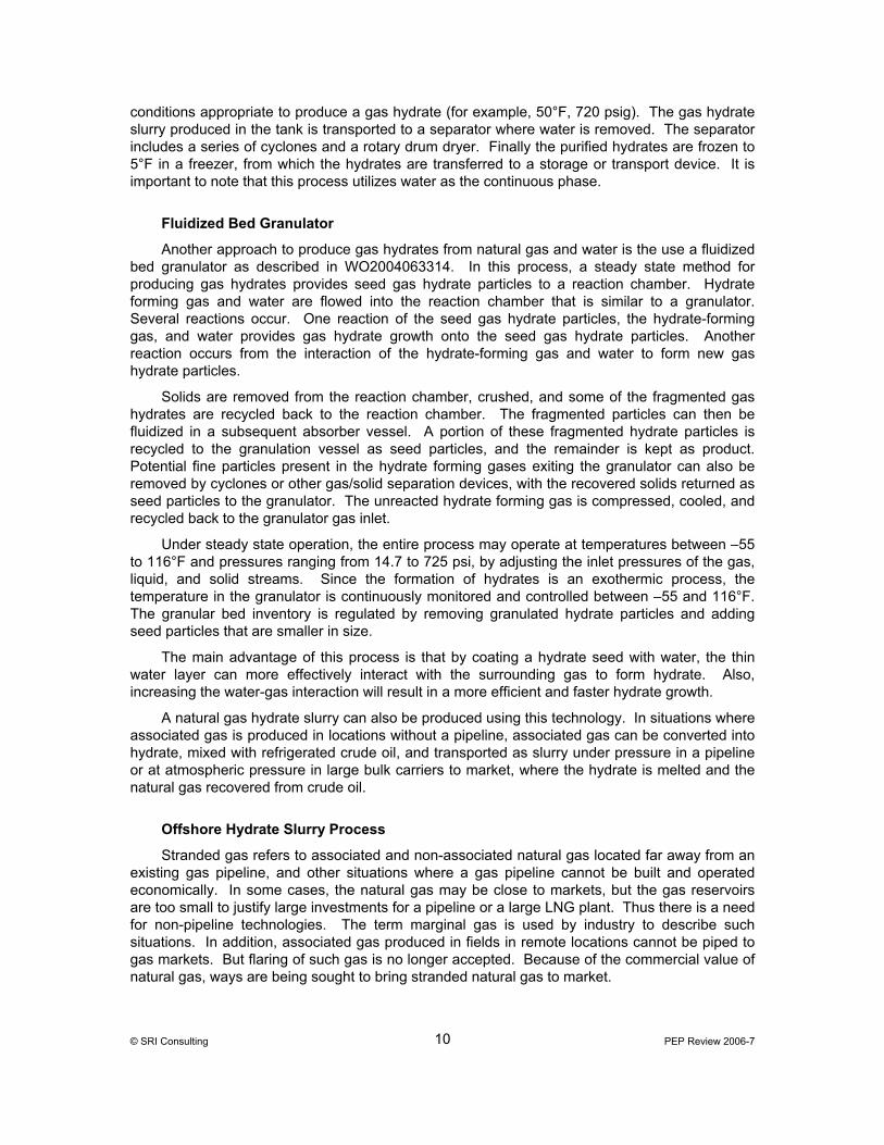
The key to this storage process is the use of surfactant spiked water solution whereby the surfactant absorbs onto the vertical metal plates. Laboratory studies demonstrated that aluminum is the best material of construction for adsorption and retention of the hydrates onto the vertical adsorption plates. This is fortunate because of the higher thermal conductivity, lighter weight and lower fabrication cost of aluminum compared to steel. The formed hydrates are packed on the surfaces of these metal plates by adsorbing onto the plates and building outwardly. Vertical plate supports are designed so that the horizontal adsorption plates withstand the weight of the full hydrate load, with a maximum deflection of only 0.5 inches over their entire length. Also the aluminum single pass heat transfer tubing is in direct contact with the supports. The aluminum plates are mounted across the entire length of the reactor vessel and can be individually removed. Aluminum heat exchange tubing extends the length of the reactor, resting on aluminum cross supports, and the heating/cooling media make one pass through each tube. Heat transfer results from conduction and convection from the tubes immersed in water and contacting the plates and supports. The reactor vessel drain and gas ports are TeflonTM coated to prevent build-up of hydrates. A single reactor vessel design is shown below in Figure 2.
Figure 2 HYDRATE REACTOR
Source: R0607116
The hydrates are formed and stored at temperature between 35-40°F. At these storage temperatures, the heat gains during storage would become prohibitive without exceptional insulation. Super insulation similar to that used in the insulation of liquefied gases, oxygen, and nitrogen is used. This insulation has to have exceptionally low thermal conductivity. The insulation is made from small diameter fiberglass fibers of about 1 micron, bonded with melamine resin to form a blanket insulation material the exhibits minimal out-gassing under vacuum at low temperature. This type of insulation is available from Johns Manville in 1” thick sheets, and has a nominal density of 1lb/ft3. At a tank temperature of 153°F, the material has a rated thermal conductivity of only 0.0023 Btu/hr-ft-°F at 0.1 Hg of pressure. As insulation thickness increases, its capital cost increases but the heat gain of the cold hydrate tank decreases. Because of the low heat gains through the insulation, storage temperatures of the gas hydrates can be maintained. In order to reduce refrigeration cost, three layers of this insulation provide a 3’ thickness installed around the circumference and ends of the cylindrical hydrate reactor, and then sealed to hold vacuum. With this design, a reasonably sized refrigeration unit can be provided to serve each hydrate reactor tank.
As mentioned above, the process design includes the use of a gas-fired refrigeration system to remove the latent heat of hydrate formation. The natural gas refrigeration unit is important for two reasons, namely the economy of fuel usage, and the utilization of methane rich gas that accumulates in the hydrate reactors. These two reasons are very much related because as the hydrates form, they occlude gas leaner in methane than in the free gas from which they form. The free gas in the reactor during hydrate formation becomes richer in methane as the process proceeds. Gas fired refrigeration uses this accumulating methane-enriched gas to supply cheaper cooling to the process by reducing the amount of methane-rich gas above the hydrates and reducing operating and storage pressures for the process.
© SRI Consulting PEP Review 2006-7 18

© SRI Consulting PEP Review 2006-7 19
Any low grade heat source at ambient or higher temperatures could be used to decompose the hydrates. In the enclosed process, use of process water at 100°F is assumed. In another setting, for example, the process could use surface water or even ambient air for circulation through the heat transfer tubing to decompose the hydrates. With reduced pressures and a relatively low equilibrium temperature, the hydrate decomposition rate is high.
COST ESTIMATES
Below, we report on the economics for the production and use of hydrates as energy storage media for a thermal energy storage system. A minimum feasible single hydrates formation/decomposition cycle time is 24 hours, without requiring product storage. Thus, the unit manufacturing capacity, including storage capability, is designed to handle one product hydrate formation/decomposition cycle time requirement.
Capital Cost
Itemized capital cost estimates are listed in Table 3 for a single cycle of methane hydrates manufacturing/storage/dissociation in a facility of 740 mm scf/yr capacity. The process itself is a semi-continuous cycle-based operation with actual annual production dependent on demand-determined capacity utilization. The total battery limits capital investment required for the above sized storage facility is about $7.9 million, including a 15% estimate contingency. Reactor vessel and gas fired glycol refrigeration investment requirements are the single most expensive capital cost items, at $2.1 and $2.0 million respectively. The reactor vessels will most likely be custom manufactured offsite and shipped to the on-site storage facility for a relatively simple installation. Likewise, the required refrigeration systems are estimated as package units.
Production Cost
Detailed raw materials, utilities, factored labor and capital based fixed costs are itemized in Tables 4 including an allowance for corporate overheads cost allocation for operation of a single cycle operated hydrates storage facility.
Figure 3 then shows the effect of increased cycling on unit product cost required to meet demand as a function of the number of total formation/decomposition cycles performed during annual operation. The economic results are then benchmarked against equivalent LNG or depleted reservoir production costs for storage and retrieval of an equivalent volume natural gas for distributed gas supply.
Not surprisingly, on a single cycle annual operations basis, labor based costs are the single largest total cash cost contributor (0.63 $/mscf) to hydrates storage costs, closely followed by raw material and utility costs (0.60 $/mscf) and then capital based operating costs (0.32 $/mscf). A 10 year depreciation replacement cost allowance for basic equipment utilization contributes (0.259 $/mscf) to total plant gate cost. Also, because reactor off gas is used as firing fuel for the refrigeration units, the single largest variable cost of 0.46$/mscf is passed through pipeline natural gas consumption.
Figure 3 shows the user cost that must be charged for our 24 hour cycle design based manufactured gas hydrates storage system. The horizontal lines indicate the comparison of cycle costs with the most and the least expensive conventional natural gas storage options.

Figure 3 COMPARISON OF HYDRATE USER COSTS WITH CONVENTIONAL STORAGE SYSTEMS
Cycle Product Costs
0.00
2.00
4.00
6.00
8.00
10.00
0 50 100 150 200 250 300 350
Cycles/yr
Prod
uct C
ost,
$/M
scf
Source: SRI Consulting
Comparative overall cost results as indicated in Figure 3 for multiple cycle operation of a hydrate based storage system show that a minimum of 40 cycles (days)/yr of formation/decomposition operation of this hydrates storage facility is required for this system to be economically competitive with the typical alternative production cost of LNG storage. Similarly a minimum of 230 cycles/yr of hydrates storage operations are required to be economically competitive with the typical production costs associated with the use of depleted gas reservoir storage. Other possible condensed or compressed natural gas storage alternatives, such as salt cavern or aquifer storage, have costs that fall in between these two extremes, with LNG being the highest storage cost and depleted reservoir storage being the lowest cost alternative.
SUMMARY
There is a distinct economic advantage for the hydrate storage process as described above because a single formation/decomposition cycle can be accomplished within a 24 hour period and numerous storage cycles can be performed in a year as required. Also technical advantages of this hydrate storage process include:
1. Storage safety – Because the gas is essentially encased in ice, only a slow release rate will result should the tank rupture (conceptually the hydrates could be stabilized indefinitely by pressurizing with an inert gas or water to further enhance safety, although this step was not included in our design. Also, the hydrate crystal stability depends on total vessel pressure, and not the equilibrium based partial pressure of the occluded gas, so direct process control is possible.
2. Low-pressure storage - A pressure of 550 psig was used as the basis for design to optimize gas capacity with cost. Conceivably the hydrates could be formed at 550 psig but stored near atmospheric pressure if a storage temperature of -20° to 0°C were maintained.
© SRI Consulting PEP Review 2006-7 20
© SRI Consulting PEP Review 2006-7 21
3. Above ground storage.
4. Attractiveness of hydrates storage economy increases as the number of storage cycles is increased.
5. The physical size of the storage facility can be any multiple or fraction of the size of the conceptual system presented in this report.
6. Application versatility – size, location, safety, simplicity make possible a wide variety of potential natural gas storage applications ranging from large power plants to remote small scale units.
7. Type sI and sII hydrates can be rapidly formed on vertical heat adsorption plates.
8. In this quiescent system design, interstitial water between packed hydrate particles is most efficiently converted to sII hydrates, thus minimizing labor and maintenance process costs.
CONCLUSIONS
The use of surfactants makes the above described process for storing natural gas in hydrate form technically feasible. The concentration of surfactant in water above the critical micelle concentration (242ppm) enhances process technical feasibility greatly. Also an ambient temperature heating medium can be used to give adequate decomposition rate. The rate and extent of potential economic deployment of this technology will most likely follow the rate of construction of distributed natural gas based power generation systems. Also the potential economic value for use of this technology will depend on the status of local and regional fuel storage alternatives. Finally, where deployment of this technology may take hold most rapidly depends on the robustness of the current local natural gas fuel infrastructure, the local underlying demand/supply situation, and the magnitude of potential business interruption costs arising from any potential short-term natural gas shortages caused by conventional production disruptions in specific regional locations.

© SRI Consulting PEP Review 2006-7 22
Table 2 NATURAL GAS HYDRATE STORAGE
MAJOR EQUIPMENT
CAPACITY: 740 BILLION SCF/YR NATURAL GAS
AT 0.90 STREAM FACTOR
EQUIPMENT NUMBER NAME SIZE MATERIAL OF CONSTRUCTION REMARKS ------------------- ---------------------------------------------- ---------------------------------------- ---------------------------------------------------------- ----------------------------------------------------------------------------------
REACTORS R-101A-C HYDRATE REACTOR 35,250 GAL SHELL: C.S. INCLUDES ADSORPTION PLATES/SUPPORTS
HEAT EXCHANGERS E-101 MAKEUP H2O EXCHANGER 1,000 SQ FT SHELL: C.S. 0.03 MMBTU/HR TUBES: C.S.
PRESSURE VESSELS V-101 BRINE COLLECTION TANK 1,014 GAL 304 SS V-102 FOAM-MIST COLLECTION 8,177 GAL C.S. V-103 GAS COOLING TANK 2,000 GAL C.S. W/HEAT EXCHANGER V-104 SURFACTANT SOLUTION 2,734 GAL C.S. W/AGITATOR+HEAT EXCHANGER
SPECIAL EQUIPMENT S-101A-C INSULATION VAC. PUMP 0.75 HP CARBON STEEL
PACKAGE UNITS G-101A-C REFRIGERATION 200 TONS CARBON STEEL GLYCOL REFRIGERATION
PUMPS
SECTION OPERATING SPARES OPERATING BHP --------------- ------------------- -------------- -------------------------
100 4 0 274

© SRI Consulting PEP Review 2006-7 23
Table 3 NATURAL GAS HYDRATE STORAGE
TOTAL CAPITAL INVESTMENT
CAPACITY: 740 MILLION SCF/YR NATURAL GAS
AT 0.90 STREAM FACTOR
PEP COST INDEX: 688
CAPACITY EXPONENT COST -------------------------- ($1,000) UP DOWN ------------ ---------- ---------- BATTERY LIMITS EQUIPMENT, F.O.B. REACTORS 1,302 0.37 0.33 VESSELS & TANKS 119 0.39 0.34 HEAT EXCHANGERS 206 0.62 0.61 SPECIAL EQUIPMENT 52 0.40 0.50 PUMPS 44 0.78 0.67 --------- TOTAL 1,723 0.42 0.37 DIRECT INSTALLATION COSTS 2,129 0.42 0.43 PACKAGE UNIT 2,094 0.70 0.70 INDIRECT COSTS 595 0.52 0.50 UNSCHEDULED EQUIPMENT, 5% 327 0.52 0.50 --------- BATTERY LIMITS, INSTALLED 6,868 0.52 0.50 CONTINGENCY, 15% 1,030 0.52 0.50 --------- BATTERY LIMITS INVESTMENT 7,898 0.52 0.50

© SRI Consulting PEP Review 2006-7 24
Table 4 NATURAL GAS HYDRATE STORAGE
PRODUCTION COSTS
PEP COST INDEX: 688
VARIABLE COSTS CONSUMPTION UNIT COST PER MSCF ¢/MSCF ------------------------- -------------------------- ---------- RAW MATERIALS SURFACTANT 1 $/LB 0.0022 LB 0.22 --------- GROSS RAW MATERIALS 0.22
CONSUMPTION CONSUMPTION UNIT COST PER MSCF PER M3 ------------------------- -------------------------- -------------------------- UTILITIES PROCESS WATER 0.845 $/MGAL 0.000384 GAL 0.0000512 LITERS NEGL ELECTRICITY 5.4 ¢/KWH 2.42 KWH 0.0855 KWH 13.08 NATURAL GAS 6.69 $/MMBTU 69,400 BTU 617 KCAL 46.41 --------- TOTAL UTILITIES 59.49

© SRI Consulting PEP Review 2006-7 25
Table 4 (Concluded) NATURAL GAS HYDRATE STORAGE
PRODUCTION COSTS
PEP COST INDEX: 688
CAPACITY (MILLION SCF/YR)* 370 740# 1480 ------------ ------------ ------------ INVESTMENT ($ MILLIONS) BATTERY LIMITS (BLI) 5.6 7.9 11.4 OFFSITES 0.6 0.6 0.6 --------- --------- --------- TOTAL FIXED CAPITAL (TFC) 6.2 8.5 11.9 SCALING EXPONENTS 0.46 0.49
PRODUCTION COSTS (¢/MSCF) RAW MATERIALS 0.22 0.22 0.22 UTILITIES 59.49 59.49 59.49 --------- --------- --------- VARIABLE COSTS 59.71 59.71 59.71 OPERATING LABOR, 1.2/SHIFT, $40.5/HR 115.06 57.53 28.77 MAINTENANCE LABOR, 0.5%/YR OF BLI 7.54 5.34 3.84 CONTROL LAB LABOR, 15% OF OPER LABOR 17.26 8.63 4.32 --------- --------- --------- LABOR COSTS 139.86 71.50 36.93 MAINTENANCE MATERIALS, 0.5%/YR OF BLI 7.54 5.34 3.84 OPERATING SUPPLIES, 1% OF OPER LABOR 1.15 0.58 0.29 --------- --------- --------- TOTAL DIRECT COSTS 208.26 137.13 100.77 PLANT OVERHEAD, 80% OF LABOR COSTS 111.89 57.20 29.54 TAXES AND INSURANCE, 3%/YR OF TFC 50.06 34.42 24.22 --------- --------- --------- PLANT CASH COSTS 370.21 228.75 154.53 DEPRECIATION, 3.2%/YR OF TFC 53.40 36.72 25.84 --------- --------- --------- PLANT GATE COSTS 423.61 265.47 180.37 G&A, SALES, RESEARCH 10.86 6.81 4.62 --------- --------- --------- NET PRODUCTION COST 434.47 272.28 184.99 ROI BEFORE TAXES, 0%/YR OF TFC NEGL NEGL NEGL --------- --------- --------- PRODUCT VALUE 434.47 272.28 184.99 ----------------------------------- * OF NATURAL GAS # BASE CASE

© SRI Consulting PEP Review 2006-7 26
CITED REFERENCES
Article's
Accession Number
R0607076 Masoudi, R.; Tohidi, B., "Gas-Hydrate Production for Natural-Gas Storage and Transportation," JPT, Journal of Petroleum Technology, 11 (2005), p 73-74
R0607092 Abegg, F.; Freitag, J.; Bohrmann, G.; Brueckmann, W.; Anonymous "Free Gas and Gas Hydrate ; Proof of the Coexistence in Marine Environment and Implication for the Hydrate Formation," AAPG annual meeting, American Association of Petroleum Geologists and Society of Economic Paleontologists and Mineralogists (AAPG), Tulsa, OK, United States, Dec 0-0, 0, 1
R0607095 Anonymous, "Gas Hydrates : a Nice Idea," Petroleum Economist (2005), 1
R0607102 Anonymous, "Pipe Cleaner," Engineer (2005), 8
R0607103 Anonymous, "Study Downgrades Gas Hydrates Potential for Northern Gulf of Mexico," Oil & Gas Journal (2005), 53-54
R0607112 Tubb, R., "Research Aimed at Mapping Inexhaustible Supply of Energy in Gulf.(OFFSHORE)(Brief Article)," Pipeline & Gas Journal, 6 (2005), 67(1)
R0607114 Gudmundsson, J.; Mork, M. "Stranded Gas to Hydrate Storage and Transport," 2001 International Gas Research Conference, November 5-8, 2001, 12
R0607115 Rogers, R. E., "Gas Hydrate Storage Process for Natural Gas," Gss Tips, Winter (December 2005), 14-18
R0607116 Rogers, R.; Zhong, Y., "Natural Gas Hydrates Storage Projece," Final, Missippiii State University (1999), 1-34
R0607117 Rogers, R., "Natural Gas Storage Project," Final, Mississippi State University (1999)
R0607118 Wegrzyn, J.; et.al., "Catalytic Routes to Transportation Fuels," Catalysis Today, 50 (1999), 97-108
R0607119 Collett, T., "Energy Resource Potential of Natural Gas Hydrates," American Association of Petroleum Geologists, 86, 11 (November 2002), 1971-1992
R0607120 Gudmundsson, V.; et.al. "Natural Gas Hydrates on FPSO - Slurry Process and Cost Estimate," Society of Petroleum Engineers Annual Technical Conference, March 10, 1999 -June 10, 1999, 1-8

© SRI Consulting PEP Review 2006-7 27
CITED REFERENCES (CONCLUDED)
Patent Number
US 5536893 Gudmundsson, J., "Method for Production of Gas Hydrates for Transportation and Storage" (July 26, 1996)
US 5950732 Agee, M.; Weick L.J.; Agee, K. (to Syntroleum Corporation), "System and Method for Hydrate Recovery" (September 14, 1999)
US 6389820 Rogers, R. Z. Y. (to Mississippi State University), "Surfactant Process for Promoting Gas Hydrate Formation and Application of Same" (May 21, 2002)
US 6774276 Lund, A.; Lysne, D.; Larsen, R.; Hjarbo, K. W. (to Sinvent AS), "Method and System for Transporting a Flow of Fluid Hydrocarbons Containing Water" (August 10, 2004)
US 6973968 Pfefferle, W. C. (to Precision Combustion), "Method of Natural Gas Production" (December 13, 2005)
US 20060070732A1 Schicks, J., "Process and Device for the Thermal Stimulation of Gas Hydrate Formations" (April 6, 2006)
WO 2004063314 Servio, P.; et.al. (to Servio, P,D, and et.al.), "Formation of Gas Hydrates by Fluidized Bed Granulation" (July 29, 2004)
WO 2006016333A1 Jardine Stuart, I.; Ayoub, J. A.; Ramakrishnan, T. S. (to Schlumberger Technology B.V.), "Method for Exploitation of Gas Hydrates" (February 16, 2006)

© SRI Consulting PEP Review 2006-7 28
PATENT ASSIGNEES
Assignee
Patent Number
Gudmundsson, J.S. US 5536893
Mississippi State University US 6389820
Precision Combustion US 6973968
Schicks, Judith US 20060070732A1
Schlumberger Technology B.V. WO 2006016333A1
Servio, P,D, and et.al. WO 2004063314
Sinvent AS US 6774276
Syntroleum Corporation US 5950732