2004 impreza service manual quick reference index...
TRANSCRIPT
2004 IMPREZA SERVICE MANUAL QUICK REFERENCE INDEX
ENGINE SECTION 1
This service manual has been preparedto provide SUBARU service personnelwith the necessary information and datafor the correct maintenance and repairof SUBARU vehicles.This manual includes the proceduresfor maintenance, disassembling, reas-sembling, inspection and adjustment ofcomponents and diagnostics for guid-ance of experienced mechanics.Please peruse and utilize this manualfully to ensure complete repair work forsatisfying our customers by keepingtheir vehicle in optimum condition.When replacement of parts duringrepair work is needed, be sure to useSUBARU genuine parts.
All information, illustration and specifi-cations contained in this manual arebased on the latest product informationavailable at the time of publicationapproval.
FUJI HEAVY INDUSTRIES LTD.
FUEL INJECTION (FUEL SYSTEMS) FU(H4SO)
EMISSION CONTROL (AUX. EMISSION CONTROL DEVICES)
EC(H4SO)
INTAKE (INDUCTION) IN(H4SO)
MECHANICAL ME(H4SO)
EXHAUST EX(H4SO)
COOLING CO(H4SO)
LUBRICATION LU(H4SO)
SPEED CONTROL SYSTEMS SP(H4SO)
IGNITION IG(H4SO)
STARTING/CHARGING SYSTEMS SC(H4SO)
ENGINE (DIAGNOSTICS) EN(H4SO)(diag)
FUEL INJECTION (FUEL SYSTEMS) FU(H4SOw/oOBD)
EMISSION CONTROL (AUX. EMISSION CONTROL DEVICES)
EC(H4SOw/oOBD)
INTAKE (INDUCTION) IN(H4SOw/oOBD)
MECHANICAL ME(H4SOw/oOBD)
EXHAUST EX(H4SOw/oOBD)
COOLING CO(H4SOw/oOBD)
G1870GE2

2004 IMPREZA SERVICE MANUAL QUICK REFERENCE INDEX
ENGINE SECTION 1
LUBRICATION LU(H4SOw/oOBD)
SPEED CONTROL SYSTEMS SP(H4SOw/oOBD)
IGNITION IG(H4SOw/oOBD)
STARTING/CHARGING SYSTEMS SC(H4SOw/oOBD)
ENGINE (DIAGNOSTICS) EN(H4SOw/oOBD)(diag)
G1870GE2

MECHANICAL
ME(H4SO)
Page1. General Description ....................................................................................22. Compression .............................................................................................263. Idle Speed .................................................................................................274. Ignition Timing...........................................................................................285. Intake Manifold Vacuum............................................................................296. Engine Oil Pressure ..................................................................................307. Fuel Pressure............................................................................................318. Valve Clearance........................................................................................329. Engine Assembly ......................................................................................34
10. Engine Mounting .......................................................................................4111. Preparation for Overhaul...........................................................................4212. V-belt.........................................................................................................4313. Crankshaft Pulley ......................................................................................4514. Timing Belt Cover......................................................................................4715. Timing Belt Assembly................................................................................4816. Camshaft Sprocket....................................................................................5317. Crankshaft Sprocket..................................................................................5518. Valve Rocker Assembly ............................................................................5619. Camshaft...................................................................................................5820. Cylinder Head Assembly...........................................................................6221. Cylinder Block ...........................................................................................6822. Engine Trouble in General ........................................................................8923. Engine Noise.............................................................................................95

MECHANICALGeneral Description
1. General DescriptionA: SPECIFICATIONS
NOTE:STD: Standard I.D.: Inner Diameter O.D.: Outer Diameter US: Undersize OS: Oversize
Engine
Model 1.6 L 2.0 L 2.5 L
TypeHorizontally opposed, liquid cooled, 4-cylinder, 4-stroke gasoline
engine
Valve arrangement Belt driven, single over-head camshaft, 4-valve/cylinder
Bore × Stroke mm (in)87.9 × 65.8
(3.46 × 2.591)92 × 75 (3.62 × 2.95)
99.5 × 79.0(3.917 × 3.110)
Displacement cm3 (cu in) 1,597 (97.45) 1,994 (121.67) 2,457 (150)
Compression ratio 10.0
Compression pressure (at 350 rpm) kPa (kg/cm2, psi) 1,020 — 1,275 (10.4 — 13.0, 148 — 185)
Number of piston rings Pressure ring: 2, Oil ring: 1
Intake valve timingOpening 10° BTDC 4° BTDC 1° BTDC
Closing 46° ABDC 48° ABDC 51° ABDC
Exhaust valve timingOpening 42° BBDC 48° BBDC 50° BBDC
Closing 10° ATDC 4° ATDC 6° ATDC
Valve clearanceIntake mm (in) 0.20±0.04 (0.0079±0.0016)
Exhaust mm (in) 0.25±0.04 (0.0098±0.0016)
Idling speed [At neutral position on MT, or “P” or “N” position on AT]
rpm
With OBD: 650±100 (No load)850±100 (A/C ON)
Without OBD: 700±100 (No load)850±100 (A/C ON)
650±100 (No load)850±100 (A/C ON)
Firing order 1 → 3 → 2 → 4
Ignition timing BTDC/rpm
With OBD: 5°±10°/650
Without OBD: 5°±10°/700
With OBD: 10°±10°/650
Without OBD: 10°±10°/700
MT: 10°±10°/650AT: 15°±10°/650
Belt tensioner adjuster
Protrusion of adjuster rod 5.2 — 6.2 mm (0.205 — 0.244 in)
Belt tensioner
Spacer O.D. 17.955 — 17.975 mm (0.7069 — 0.7077 in)
Tensioner bush I.D. 18.00 — 18.08 mm (0.7087 — 0.7118 in)
Clearance between spacer and bushSTD 0.025 — 0.125 mm (0.0010 — 0.0049 in)
Limit 0.175 mm (0.0069 in)
Side clearance of spacerSTD 0.20 — 0.55 mm (0.0079 — 0.0217 in)
Limit 0.81 mm (0.0319 in)
Valve rocker arm
Clearance between shaft and armSTD 0.020 — 0.054 mm (0.0008 — 0.0021 in)
Limit 0.10 mm (0.0039 in)
ME(H4SO)-2

MECHANICALGeneral Description
Camshaft
Bend limit 0.025 mm (0.0010 in)
Thrust clearanceSTD 0.030 — 0.090 mm (0.0012 — 0.0035 in)
Limit 0.10 mm (0.0039 in)
Cam lobe height
1.6 L
IntakeSTD 39.378 — 39.478 mm (1.5503 — 1.5542 in)
Limit 39.278 mm (1.5464 in)
ExhaustSTD 39.565 — 39.665 mm (1.5577 — 1.5616 in)
Limit 39.465 mm (1.5537 in)
2.0 L
IntakeSTD 38.732 — 38.832 mm (1.5249 — 1.5288 in)
Limit 38.632 mm (1.5209 in)
ExhaustSTD 39.257 — 39.357 mm (1.5455 — 1.5495 in)
Limit 39.157 mm (1.5416 in)
2.5 L
IntakeSTD 39.485 — 39.585 mm (1.5545 — 1.5585 in)
Limit 39.385 mm (1.5506 in)
ExhaustSTD 39.257 — 39.357 mm (1.5455 — 1.5495 in)
Limit 39.157 mm (1.5416 in)
Camshaft journal O.D. 31.928 — 31.945 mm (1.2570 — 1.2577 in)
Camshaft journal hole I.D. 32.000 — 32.018 mm (1.2598 — 1.2605 in)
Oil clearanceSTD 0.055 — 0.090 mm (0.0022 — 0.0035 in)
Limit 0.10 mm (0.0039 in)
Cylinder head
Surface warpage limit 0.05 mm (0.0020 in)
Surface grinding limit 0.1 mm (0.004 in)
Standard height 97.5 mm (3.84 in)
Valve seat
Refacing angle 90°
Contacting width
IntakeSTD 1.0 mm (0.039 in)
Limit 1.7 mm (0.067 in)
ExhaustSTD 1.5 mm (0.059 in)
Limit 2.2 mm (0.087 in)
Valve guide
Inner diameter 6.000 — 6.012 mm (0.2362 — 0.2367 in)
Protrusion above headIntake 20.0 — 20.5 mm (0.787 — 0.807 in)
Exhaust 16.5 — 17.0 mm (0.650 — 0.669 in)
Valve
Head edge thickness
IntakeSTD 1.0 mm (0.039 in)
Limit 0.6 mm (0.024 in)
ExhaustSTD 1.2 mm (0.047 in)
Limit 0.6 mm (0.024 in)
Stem diameterIntake 5.950 — 5.965 mm (0.2343 — 0.2348 in)
Exhaust 5.945 — 5.960 mm (0.2341 — 0.2346 in)
Stem oil clearanceSTD
Intake 0.035 — 0.062 mm (0.0014 — 0.0024 in)
Exhaust 0.040 — 0.067 mm (0.0016 — 0.0026 in)
Limit — 0.15 mm (0.0059 in)
Overall lengthIntake 120.6 mm (4.75 in)
Exhaust 121.7 mm (4.79 in)
Valve spring
Free length 54.30 mm (2.1378 in)
Squareness 2.5°, 2.4 mm (0.094 in)
Tension/spring heightSet
214 — 246 N (22 — 25 kgf, 48 — 55 lb)/45.0 mm (1.772 in)
Lift526 — 582 N (54 — 59 kgf, 119 — 130 lb)/
34.7 mm (1.366 in)
ME(H4SO)-3
MECHANICALGeneral Description
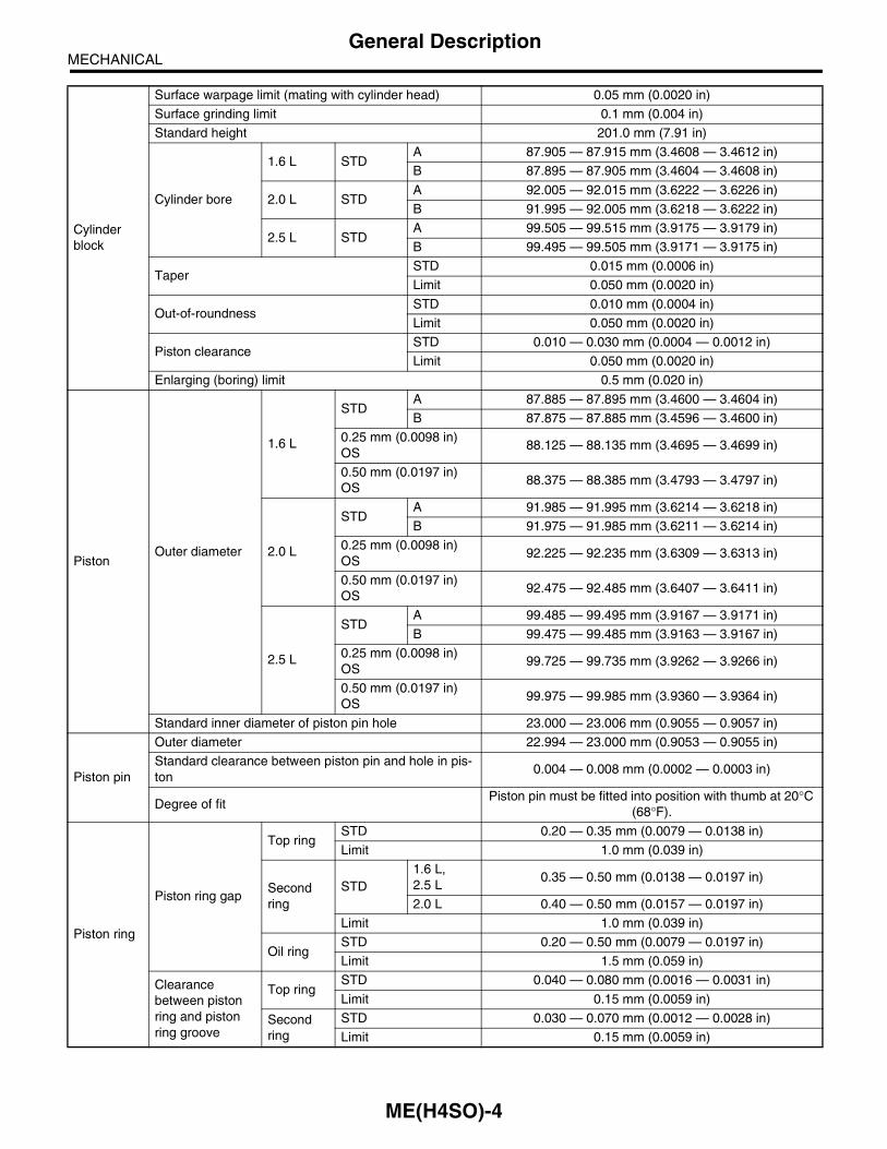
Cylinder block
Surface warpage limit (mating with cylinder head) 0.05 mm (0.0020 in)
Surface grinding limit 0.1 mm (0.004 in)
Standard height 201.0 mm (7.91 in)
Cylinder bore
1.6 L STDA 87.905 — 87.915 mm (3.4608 — 3.4612 in)
B 87.895 — 87.905 mm (3.4604 — 3.4608 in)
2.0 L STDA 92.005 — 92.015 mm (3.6222 — 3.6226 in)
B 91.995 — 92.005 mm (3.6218 — 3.6222 in)
2.5 L STDA 99.505 — 99.515 mm (3.9175 — 3.9179 in)
B 99.495 — 99.505 mm (3.9171 — 3.9175 in)
TaperSTD 0.015 mm (0.0006 in)
Limit 0.050 mm (0.0020 in)
Out-of-roundnessSTD 0.010 mm (0.0004 in)
Limit 0.050 mm (0.0020 in)
Piston clearanceSTD 0.010 — 0.030 mm (0.0004 — 0.0012 in)
Limit 0.050 mm (0.0020 in)
Enlarging (boring) limit 0.5 mm (0.020 in)
PistonOuter diameter
1.6 L
STDA 87.885 — 87.895 mm (3.4600 — 3.4604 in)
B 87.875 — 87.885 mm (3.4596 — 3.4600 in)
0.25 mm (0.0098 in) OS
88.125 — 88.135 mm (3.4695 — 3.4699 in)
0.50 mm (0.0197 in) OS
88.375 — 88.385 mm (3.4793 — 3.4797 in)
2.0 L
STDA 91.985 — 91.995 mm (3.6214 — 3.6218 in)
B 91.975 — 91.985 mm (3.6211 — 3.6214 in)
0.25 mm (0.0098 in) OS
92.225 — 92.235 mm (3.6309 — 3.6313 in)
0.50 mm (0.0197 in) OS
92.475 — 92.485 mm (3.6407 — 3.6411 in)
2.5 L
STDA 99.485 — 99.495 mm (3.9167 — 3.9171 in)
B 99.475 — 99.485 mm (3.9163 — 3.9167 in)
0.25 mm (0.0098 in) OS
99.725 — 99.735 mm (3.9262 — 3.9266 in)
0.50 mm (0.0197 in) OS
99.975 — 99.985 mm (3.9360 — 3.9364 in)
Standard inner diameter of piston pin hole 23.000 — 23.006 mm (0.9055 — 0.9057 in)
Piston pin
Outer diameter 22.994 — 23.000 mm (0.9053 — 0.9055 in)
Standard clearance between piston pin and hole in pis-ton
0.004 — 0.008 mm (0.0002 — 0.0003 in)
Degree of fitPiston pin must be fitted into position with thumb at 20°C
(68°F).
Piston ring
Piston ring gap
Top ringSTD 0.20 — 0.35 mm (0.0079 — 0.0138 in)
Limit 1.0 mm (0.039 in)
Second ring
STD1.6 L, 2.5 L
0.35 — 0.50 mm (0.0138 — 0.0197 in)
2.0 L 0.40 — 0.50 mm (0.0157 — 0.0197 in)
Limit 1.0 mm (0.039 in)
Oil ringSTD 0.20 — 0.50 mm (0.0079 — 0.0197 in)
Limit 1.5 mm (0.059 in)
Clearance between piston ring and piston ring groove
Top ringSTD 0.040 — 0.080 mm (0.0016 — 0.0031 in)
Limit 0.15 mm (0.0059 in)
Second ring
STD 0.030 — 0.070 mm (0.0012 — 0.0028 in)
Limit 0.15 mm (0.0059 in)
ME(H4SO)-4

MECHANICALGeneral Description
Connecting rod
Bend twist per 100 mm (3.94 in) in length
Limit 0.10 mm (0.0039 in)
Side clearanceSTD 0.070 — 0.330 mm (0.0028 — 0.0130 in)
Limit 0.4 mm (0.016 in)
Connecting rod bearing
Oil clearance
1.6 L2.0 L
STD 0.010 — 0.038 mm (0.0004 — 0.0015 in)
Limit 0.05 mm (0.0020 in)
2.5 LSTD 0.020 — 0.046 mm (0.0008 — 0.0018 in)
Limit 0.05 mm (0.0020 in)
Thickness at cen-ter portion
1.6 L2.0 L
STD 1.492 — 1.501 mm (0.0587 — 0.0591 in)
0.03 mm (0.0012 in) US
1.510 — 1.513 mm (0.0594 — 0.0596 in)
0.05 mm (0.0020 in) US
1.520 — 1.523 mm (0.0598 — 0.0600 in)
0.25 mm (0.0098 in) US
1.620 — 1.623 mm (0.0638 — 0.0639 in)
2.5 L
STD 1.490 — 1.502 mm (0.0587 — 0.0591 in)
0.03 mm (0.0012 in) US
1.504 — 1.512 mm (0.0592 — 0.0595 in)
0.05 mm (0.0020 in) US
1.514 — 1.522 mm (0.0596 — 0.0599 in)
0.25 mm (0.0098 in) US
1.614 — 1.622 mm (0.0635 — 0.0639 in)
Connecting rod bushing
Clearance between piston pin and bushing
STD 0 — 0.022 mm (0 — 0.0009 in)
Limit 0.030 mm (0.0012 in)
ME(H4SO)-5

MECHANICALGeneral Description
Crankshaft
Bend limit 0.035 mm (0.0014 in)
Crank pin and crank journal
Out-of-roundness 0.020 mm (0.0008 in) or less
Grinding limit 0.250 mm (0.0098 in)
Crank pin outer diameter
1.6 L
STD 47.984 — 48.000 mm (1.8891 — 1.8898 in)
0.03 mm (0.0012 in) US
47.954 — 47.970 mm (1.8879 — 1.8886 in)
0.05 mm (0.0020 in) US
47.934 — 47.950 mm (1.8872 — 1.8878 in)
0.25 mm (0.0098 in) US
47.734 — 47.750 mm (1.8793 — 1.8799 in)
2.0 L2.5 L
STD 51.984 — 52.000 mm (2.0466 — 2.0472 in)
0.03 mm (0.0012 in) US
51.954 — 51.970 mm (2.0454 — 2.0461 in)
0.05 mm (0.0020 in) US
51.934 — 51.950 mm (2.0446 — 2.0453 in)
0.25 mm (0.0098 in) US
51.734 — 51.750 mm (2.0368 — 2.0374 in)
Crank journal outer diameter
#1, #3
STD 59.992 — 60.008 mm (2.3619 — 2.3625 in)
0.03 mm (0.0012 in) US
59.962 — 59.978 mm (2.3607 — 2.3613 in)
0.05 mm (0.0020 in) US
59.942 — 59.958 mm (2.3599 — 2.3605 in)
0.25 mm (0.0098 in) US
59.742 — 59.758 mm (2.3520 — 2.3527 in)
#2, #4, #5
STD 59.992 — 60.008 mm (2.3619 — 2.3625 in)
0.03 mm (0.0012 in) US
59.962 — 59.978 mm (2.3607 — 2.3613 in)
0.05 mm (0.0020 in) US
59.942 — 59.958 mm (2.3599 — 2.3605 in)
0.25 mm (0.0098 in) US
59.742 — 59.758 mm (2.3520 — 2.3527 in)
Thrust clearanceSTD 0.030 — 0.115 mm (0.0012 — 0.0045 in)
Limit 0.25 mm (0.0098 in)
Oil clearance
#1STD 0.010 — 0.030 mm (0.0004 — 0.0012 in)
Limit 0.040 mm (0.0016 in)
#2STD 0.010 — 0.030 mm (0.0004 — 0.0012 in)
Limit 0.045 mm (0.0018 in)
#3STD 0.010 — 0.030 mm (0.0004 — 0.0012 in)
Limit 0.040 mm (0.0016 in)
#4STD 0.010 — 0.030 mm (0.0004 — 0.0012 in)
Limit 0.045 mm (0.0018 in)
#5STD 0.010 — 0.030 mm (0.0004 — 0.0012 in)
Limit 0.040 mm (0.0016 in)
ME(H4SO)-6
MECHANICALGeneral Description
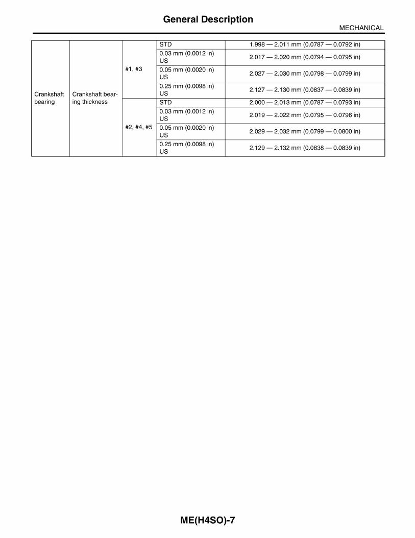
Crankshaft bearing
Crankshaft bear-ing thickness
#1, #3
STD 1.998 — 2.011 mm (0.0787 — 0.0792 in)
0.03 mm (0.0012 in) US
2.017 — 2.020 mm (0.0794 — 0.0795 in)
0.05 mm (0.0020 in) US
2.027 — 2.030 mm (0.0798 — 0.0799 in)
0.25 mm (0.0098 in) US
2.127 — 2.130 mm (0.0837 — 0.0839 in)
#2, #4, #5
STD 2.000 — 2.013 mm (0.0787 — 0.0793 in)
0.03 mm (0.0012 in) US
2.019 — 2.022 mm (0.0795 — 0.0796 in)
0.05 mm (0.0020 in) US
2.029 — 2.032 mm (0.0799 — 0.0800 in)
0.25 mm (0.0098 in) US
2.129 — 2.132 mm (0.0838 — 0.0839 in)
ME(H4SO)-7
MECHANICALGeneral Description
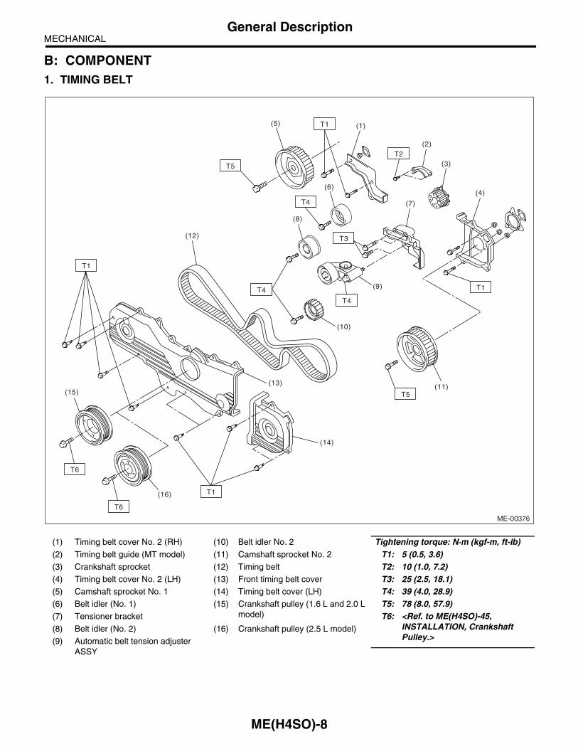
B: COMPONENT1. TIMING BELT
(1) Timing belt cover No. 2 (RH) (10) Belt idler No. 2 Tightening torque: N·m (kgf-m, ft-lb)(2) Timing belt guide (MT model) (11) Camshaft sprocket No. 2 T1: 5 (0.5, 3.6)(3) Crankshaft sprocket (12) Timing belt T2: 10 (1.0, 7.2)(4) Timing belt cover No. 2 (LH) (13) Front timing belt cover T3: 25 (2.5, 18.1)(5) Camshaft sprocket No. 1 (14) Timing belt cover (LH) T4: 39 (4.0, 28.9)(6) Belt idler (No. 1) (15) Crankshaft pulley (1.6 L and 2.0 L
model)T5: 78 (8.0, 57.9)
(7) Tensioner bracket T6: <Ref. to ME(H4SO)-45, INSTALLATION, Crankshaft Pulley.>
(8) Belt idler (No. 2) (16) Crankshaft pulley (2.5 L model)
(9) Automatic belt tension adjuster ASSY
ME-00376
T5
T4
T1
T1
T6
T5
(5)
(6)
(8)
(9)
(11)
(10)
(14)
(15)
(16)
(12)
(13)
(7)
(4)
(1)
(2)
(3)
T1
T2
T1
T3
T4
T6
T4
ME(H4SO)-8

MECHANICALGeneral Description
2. CYLINDER HEAD AND CAMSHAFT
(1) Rocker cover (RH) (11) Cylinder head (LH) Tightening torque: N·m (kgf-m, ft-lb)(2) Intake valve rocker ASSY (12) Camshaft (LH) T1: <Ref. to ME(H4SO)-62,
INSTALLATION, Cylinder Head Assembly.>
(3) Exhaust valve rocker ASSY (13) Camshaft cap (LH)
(4) Camshaft cap (RH) (14) Oil filler cap
(5) Oil seal (15) Gasket T2: 5 (0.5, 3.6)(6) Camshaft (RH) (16) Oil filler duct T3: 10 (1.0, 7.2)(7) Plug (17) O-ring T4: 18 (1.8, 13.0)(8) Spark plug pipe gasket (18) Rocker cover (LH) T5: 25 (2.5, 18.1)(9) Cylinder head (RH) (19) Stud bolt T6: 6.4 (0.65, 4.7)
(10) Cylinder head gasket
ME-00186
(17)
(10)
(11)(19)
(12)
(13)
(14)
(15)
(16)
(18)
(2)
(3)
(8)
(5)
(1)
(2)
(3)
(4)
(8)
(6) (7)
(8)
(7)
(9)
(10)
(19)
T2
T5
(5)
T4
T5
T6
T1
T1
T3
T5
T2T3
T3
T4T3
T4
ME(H4SO)-9

MECHANICALGeneral Description
3. VALVE ROCKER ASSEMBLY
(1) Intake valve rocker arm (5) Rocker shaft support Tightening torque: N·m (kgf-m, ft-lb)(2) Valve rocker nut (6) Intake rocker shaft T1: 5 (0.5, 3.6)(3) Valve rocker adjust screw (7) Exhaust rocker shaft T2: 10 (1.0, 7.2)(4) Spring (8) Exhaust valve rocker arm T3: 25 (2.5, 18.1)
ME-00187
(2)
(2)
(2)
(3)
(3)
(3)
(3)
(4)
(5)(4)
(1) (2)
(6)
(8)
(7)
(1)
(2)
(2)
(3)
(3)
(4)
(4)
(1)
(5)
(1)
T2
T1
T3
T1
T2
T3
T2
T2
ME(H4SO)-10

MECHANICALGeneral Description
4. CYLINDER HEAD AND VALVE ASSEMBLY
(1) Exhaust valve (4) Valve spring seat (7) Retainer
(2) Intake valve (5) Intake valve oil seal (8) Retainer key
(3) Valve guide (6) Valve spring (9) Exhaust valve oil seal
ME-00760
(2)
(2)
(6)
(6)
(3)
(3)
(4)
(4)
(5)
(9)
(7)(8)
(7)
(8)
(1)(1)
ME(H4SO)-11
MECHANICALGeneral Description
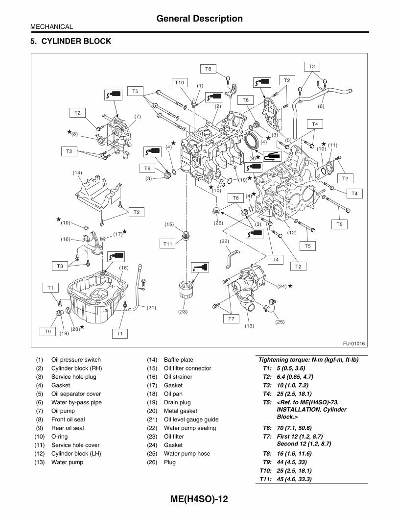
5. CYLINDER BLOCK
(1) Oil pressure switch (14) Baffle plate Tightening torque: N·m (kgf-m, ft-lb)(2) Cylinder block (RH) (15) Oil filter connector T1: 5 (0.5, 3.6)(3) Service hole plug (16) Oil strainer T2: 6.4 (0.65, 4.7)(4) Gasket (17) Gasket T3: 10 (1.0, 7.2)(5) Oil separator cover (18) Oil pan T4: 25 (2.5, 18.1)(6) Water by-pass pipe (19) Drain plug T5: <Ref. to ME(H4SO)-73,
INSTALLATION, Cylinder Block.>
(7) Oil pump (20) Metal gasket
(8) Front oil seal (21) Oil level gauge guide
(9) Rear oil seal (22) Water pump sealing T6: 70 (7.1, 50.6)(10) O-ring (23) Oil filter T7: First 12 (1.2, 8.7)
Second 12 (1.2, 8.7)(11) Service hole cover (24) Gasket
(12) Cylinder block (LH) (25) Water pump hose T8: 16 (1.6, 11.6)(13) Water pump (26) Plug T9: 44 (4.5, 33)
T10: 25 (2.5, 18.1)T11: 45 (4.6, 33.3)
FU-01016
(14)
T6
T7
T2
T2
T4
T8
T4
T5
T2
T6
T6
T10
T1
T2
T11
T1
T3
T9
T2
T2(9)
(8)
(7)
(6)
(10)
(10)
(10)
(26)
(22)
(11)
(12)
(13)
(19)
(18)
(20)
(17)(16)
(24)
(10)
(25)
(5)(4)(4)
(4)
(3)
(3)
(3)
(2)
(1)
(21)
(15)
(23)
T5
T2
T5
T4
ME(H4SO)-12

MECHANICALGeneral Description
6. CRANKSHAFT AND PISTON
ME-00190
T1
T1
(9)
(1)
(16)(17)
(16)
(17)
(6)(5)
(4)
(3)
(2)
(12)
(11)
(10)
(7)(9)
(9)
(8)
(6)(5)(4)
(15)
(18)
(9) (8)
(10)
(12)(11)
(7)
(13)
(12)
(14)
T2
T2
ME(H4SO)-13

MECHANICALGeneral Description
(1) Flywheel (MT model) (9) Circlip (17) Crankshaft bearing #2, #4
(2) Reinforcement (AT model) (10) Connecting rod bolt (18) Crankshaft bearing #5
(3) Drive plate (AT model) (11) Connecting rod
(4) Top ring (12) Connecting rod bearing Tightening torque: N·m (kgf-m, ft-lb)(5) Second ring (13) Connecting rod cap T1: 45 (4.6, 33.3)(6) Oil ring (14) Crankshaft T2: 72 (7.3, 52.8)(7) Piston (15) Woodruff key
(8) Piston pin (16) Crankshaft bearing #1, #3
ME(H4SO)-14

MECHANICALGeneral Description
7. ENGINE MOUNTING
(1) Front cushion rubber (2) Front engine mounting bracket Tightening torque: N·m (kgf-m, ft-lb)T1: 35 (3.6, 25.8)T2: 42 (4.3, 31.0)T3: 85 (8.7, 63)
ME-00413
T2
T1
T1
T3
T3
(2)
(2)
(1)
(1)
T2
ME(H4SO)-15

MECHANICALGeneral Description
C: CAUTION• Wear working clothing, including a cap, protec-tive goggles and protective shoes during operation.• Remove contamination including dirt and corro-sion before removal, installation or disassembly.• Keep the disassembled parts in order and pro-tect them from dust or dirt.• Before removal, installation or disassembly, besure to clarify the failure. Avoid unnecessary re-moval, installation, disassembly, and replacement.• Be careful not to burn your hands, because eachpart in the vehicle is hot after running.• Be sure to tighten fasteners including bolts andnuts to the specified torque.• Place shop jacks or rigid racks at the specifiedpoints.• Before disconnecting electrical connectors ofsensors or units, be sure to disconnect the groundcable from battery.• All parts should be thoroughly cleaned, payingspecial attention to the engine oil passages, pis-tons and bearings.• Rotating parts and sliding parts such as piston,bearing and gear should be coated with oil prior toassembly.
• Be careful not to let oil, grease or coolant contactthe timing belt, clutch disc and flywheel.• All removed parts, if to be reused, should be re-installed in the original positions and directions.• Bolts, nuts and washers should be replaced withnew ones as required.• Even if necessary inspections have been madein advance, proceed with assembly work whilemaking rechecks.• Remove or install engine in an area where chainhoists, lifting devices, etc. are available for readyuse.• Be sure not to damage coated surfaces of bodypanels with tools or stain seats and windows withcoolant or oil. Place a cover over fenders, as re-quired, for protection.• Prior to starting work, prepare the following:Service tools, clean cloth, containers to catch cool-ant and oil, wire ropes, chain hoist, transmissionjacks, etc.• Lift-up or lower the vehicle when necessary.Make sure to support the correct positions.
D: PREPARATION TOOL1. SPECIAL TOOLS
ILLUSTRATION TOOL NUMBER DESCRIPTION REMARKS
18231AA010 CAMSHAFT SPROCKET WRENCH
• Used for removing and installing camshaft sprocket. (LH side)• Also the CAMSHAFT SPROCKET WRENCH (499207100) can be used.
24082AA230 CARTRIDGE Troubleshooting for electrical systems.ST18231AA010
ST24082AA230
ME(H4SO)-16
MECHANICALGeneral Description
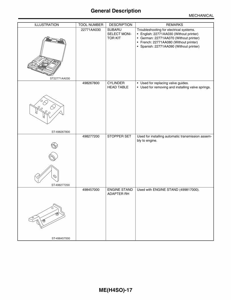
22771AA030 SUBARU SELECT MONI-TOR KIT
Troubleshooting for electrical systems.• English: 22771AA030 (Without printer)• German: 22771AA070 (Without printer)• French: 22771AA080 (Without printer)• Spanish: 22771AA090 (Without printer)
498267800 CYLINDER HEAD TABLE
• Used for replacing valve guides.• Used for removing and installing valve springs.
498277200 STOPPER SET Used for installing automatic transmission assem-bly to engine.
498457000 ENGINE STAND ADAPTER RH
Used with ENGINE STAND (499817000).
ILLUSTRATION TOOL NUMBER DESCRIPTION REMARKS
ST22771AA030
ST-498267800
ST-498277200
ST-498457000
ME(H4SO)-17
MECHANICALGeneral Description
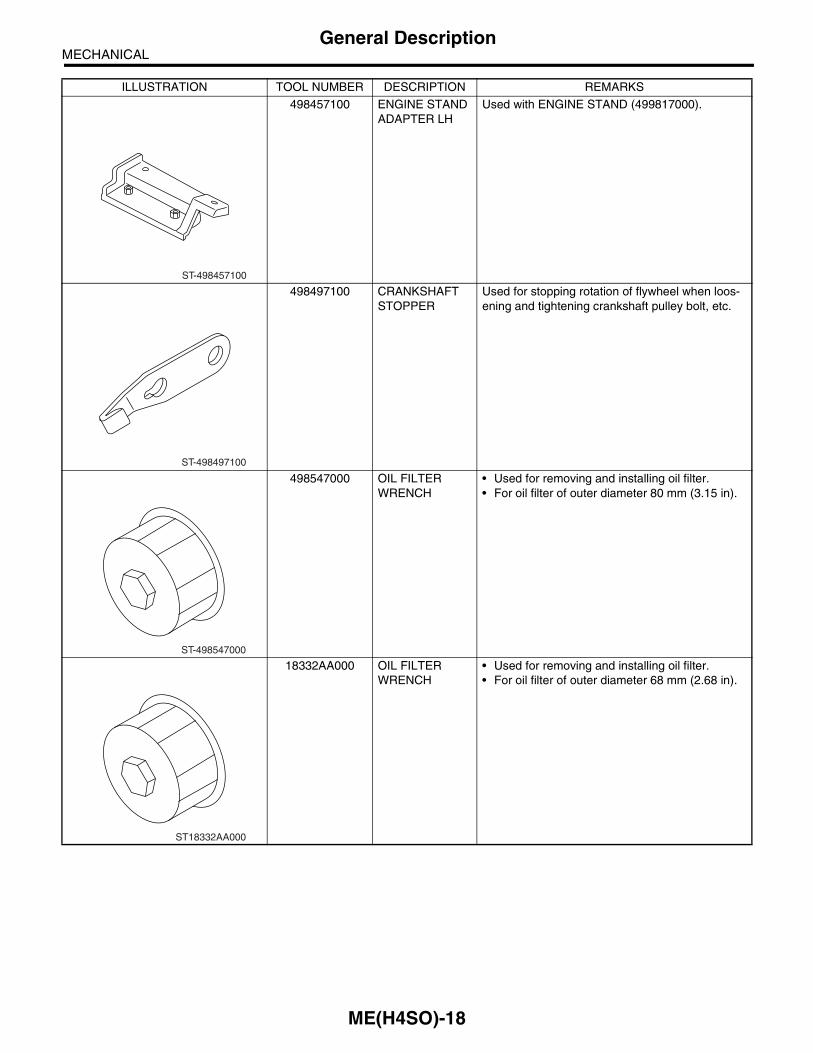
498457100 ENGINE STAND ADAPTER LH
Used with ENGINE STAND (499817000).
498497100 CRANKSHAFT STOPPER
Used for stopping rotation of flywheel when loos-ening and tightening crankshaft pulley bolt, etc.
498547000 OIL FILTER WRENCH
• Used for removing and installing oil filter.• For oil filter of outer diameter 80 mm (3.15 in).
18332AA000 OIL FILTER WRENCH
• Used for removing and installing oil filter.• For oil filter of outer diameter 68 mm (2.68 in).
ILLUSTRATION TOOL NUMBER DESCRIPTION REMARKS
ST-498457100
ST-498497100
ST-498547000
ST18332AA000
ME(H4SO)-18

MECHANICALGeneral Description
498747000 PISTON GUIDE Used for installing piston in cylinder.(1.6 L model)
398744300 PISTON GUIDE Used for installing piston in cylinder.(2.0 L model)
498747300 PISTON GUIDE Used for installing piston in cylinder. (2.5 L model)
498857100 VALVE OIL SEAL GUIDE
Used for press-fitting of intake and exhaust valve guide oil seals.
ILLUSTRATION TOOL NUMBER DESCRIPTION REMARKS
ST-498747000
ST-398744300
ST-498747300
ST-498857100
ME(H4SO)-19
MECHANICALGeneral Description
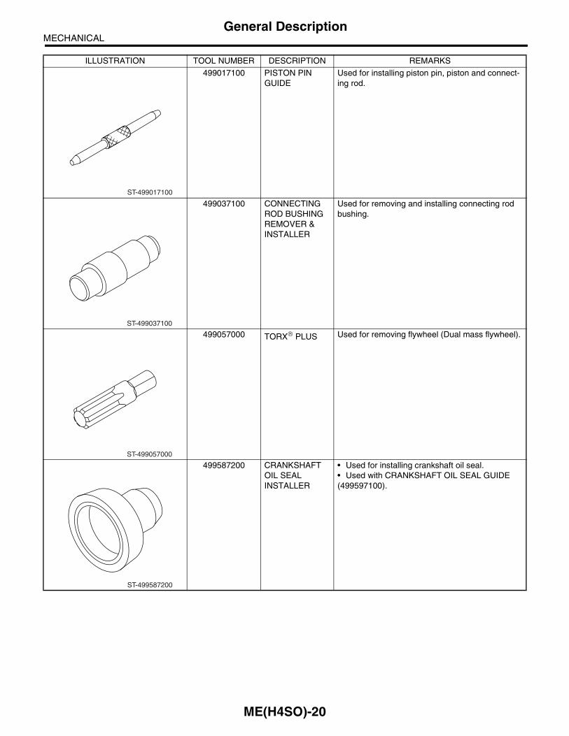
499017100 PISTON PIN GUIDE
Used for installing piston pin, piston and connect-ing rod.
499037100 CONNECTING ROD BUSHING REMOVER & INSTALLER
Used for removing and installing connecting rod bushing.
499057000 TORX PLUS Used for removing flywheel (Dual mass flywheel).
499587200 CRANKSHAFT OIL SEAL INSTALLER
• Used for installing crankshaft oil seal.• Used with CRANKSHAFT OIL SEAL GUIDE (499597100).
ILLUSTRATION TOOL NUMBER DESCRIPTION REMARKS
ST-499017100
ST-499037100
ST-499057000
ST-499587200
ME(H4SO)-20
MECHANICALGeneral Description
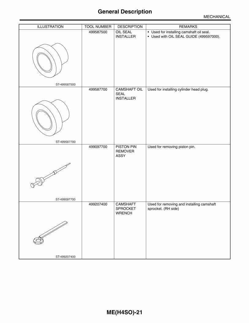
499587500 OIL SEAL INSTALLER
• Used for installing camshaft oil seal.• Used with OIL SEAL GUIDE (499597000).
499587700 CAMSHAFT OIL SEAL INSTALLER
Used for installing cylinder head plug.
499097700 PISTON PIN REMOVER ASSY
Used for removing piston pin.
499207400 CAMSHAFT SPROCKET WRENCH
Used for removing and installing camshaft sprocket. (RH side)
ILLUSTRATION TOOL NUMBER DESCRIPTION REMARKS
ST-499587500
ST-499587700
ST-499097700
ST-499207400
ME(H4SO)-21

MECHANICALGeneral Description
499497000 TORX PLUS Used for removing and installing camshaft cap.
499587100 OIL SEAL INSTALLER
Used for installing oil pump oil seal.
499597000 OIL SEAL GUIDE • Used for installing camshaft oil seal.• Used with CAMSHAFT OIL SEAL INSTALLER (499587500).
499597100 CRANKSHAFT OIL SEAL GUIDE
• Used for installing crankshaft oil seal.• Used with CRANKSHAFT OIL SEAL INSTALLER (499587200).
ILLUSTRATION TOOL NUMBER DESCRIPTION REMARKS
ST-499497000
ST-499587100
ST-499597000
ST-499597100
ME(H4SO)-22

MECHANICALGeneral Description
499718000 VALVE SPRING REMOVER
Used for removing and installing valve spring.
499767200 VALVE GUIDE REMOVER
Used for removing valve guides.
499767400 VALVE GUIDE REAMER
Used for reaming valve guides.
499767700 VALVE GUIDE ADJUSTER
Used for installing valve guide. (Intake side)
ILLUSTRATION TOOL NUMBER DESCRIPTION REMARKS
ST-499718000
ST-499767200
ST-499767400
ST-499767700
ME(H4SO)-23

MECHANICALGeneral Description
499767800 VALVE GUIDE ADJUSTER
Used for installing valve guide. (Exhaust side)
499817100 ENGINE STAND • Stand used for engine disassembly and assem-bly.• Used with ENGINE STAND ADAPTER RH (498457000) & LH (498457100).
499977400 CRANKSHAFT PULLEY WRENCH
Used for stopping rotation of crankshaft pulley when loosening and tightening crankshaft pulley bolts. (1.6 L and 2.0 L model)
499977100 CRANKSHAFT PULLEY WRENCH
Used for stopping rotation of crankshaft pulley when loosening and tightening crankshaft pulley bolts. (2.5 L model)
ILLUSTRATION TOOL NUMBER DESCRIPTION REMARKS
ST-499767700
ST-499817100
ST-499977400
ST-499977100
ME(H4SO)-24

MECHANICALGeneral Description
2. GENERAL PURPOSE TOOLS
E: PROCEDUREIt is possible to conduct the following service proce-dures with engine on the vehicle, however, the pro-cedures described in this section are based on thecondition that the engine is removed from the vehi-cle.• V-belt• Timing Belt• Valve Rocker Assembly• Camshaft• Cylinder Head
499987500 CRANKSHAFT SOCKET
Used for rotating crankshaft.
499897200 PISTON CIR-CLIP PLIERS
Used for removing and installing piston pin circlip.
TOOL NAME REMARKS
Compression Gauge Used for measuring compression.
Tachometer (Secondary pick-up type) Used for measuring idle speed.
Timing Light Used for measuring ignition timing.
ILLUSTRATION TOOL NUMBER DESCRIPTION REMARKS
ST-499987500
ST-499897200
ME(H4SO)-25

MECHANICALCompression
2. CompressionA: INSPECTIONCAUTION:After warming up, engine becomes very hot. Be careful not to burn yourself during measure-ment.1) After warming up the engine, turn the ignitionswitch to OFF.2) Make sure that the battery is fully charged.3) Lower the fuel pressure. <Ref. to FU(H4SO)-50,RELEASING OF FUEL PRESSURE, OPERA-TION, Fuel.> or <Ref. to FU(H4SOw/oOBD)-46,RELEASING OF FUEL PRESSURE, OPERA-TION, Fuel.>4) Remove all the spark plugs. <Ref. to IG(H4SO)-5, REMOVAL, Spark Plug.>5) Fully open the throttle valve.6) Check the starter motor for satisfactory perfor-mance and operation.7) Hold the compression gauge tight against sparkplug hole.
NOTE:When using a screw-in type compression gauge,the screw (put into cylinder head spark plug hole)should be less than 18 mm (0.71 in) long.8) Crank the engine by means of starter motor, andthen read the maximum value on the gauge whenthe pointer is steady.
9) Perform at least two measurements per cylinder,and make sure that the values are correct.
Compression (350 rpm and fully open throttle):Standard;
1,275 kPa (13.0 kgf/cm2, 185 psi)Limit;
1,020 kPa (10.4 kgf/cm2, 148 psi)Difference between cylinders;
49 kPa (0.5 kgf/cm2, 7 psi), or less
ME-00192
ME(H4SO)-26

MECHANICALIdle Speed
3. Idle SpeedA: INSPECTION1) Before checking idle speed, check the following:
(1) Ensure the air cleaner element is free fromclogging, ignition timing is correct, spark plugsare in good condition, and the hoses are con-nected properly.(2) Ensure the malfunction indicator light doesnot illuminate.
2) Warm up the engine.3) Stop the engine, and then turn the ignition switchto OFF.4) When using the Subaru Select Monitor, refer tothe following. <Ref. to ME(H4SO)-16, SPECIALTOOLS, PREPARATION TOOL, General Descrip-tion.>
(1) Insert the cartridge to Subaru Select Moni-tor.(2) Connect the Subaru Select Monitor to datalink connector.
(3) Turn the ignition switch to ON, and SubaruSelect Monitor switch to ON.(4) Select the {2. Each System Check} in MainMenu.(5) Select the {Engine Control System} in Se-lection Menu.(6) Select the {1. Current Data Display & Save}in Engine Control System Diagnosis.(7) Select the {1.12 Data Display} in Data Dis-play Menu.(8) Start the engine, and then read the engineidle speed.
5) When using the tachometer (Secondary pick-uptype).
(1) Attach the pick-up clip to No. 1 cylinderspark plug cord.
(2) Start the engine, and then read the engineidle speed.
NOTE:• When using the OBD-II general scan tool, care-fully read its operation manual.• This ignition system provides simultaneous igni-tion for #1 and #2 plugs. It must be noted that sometachometers may register twice that of actual en-gine speed.6) Check the idle speed when unloaded. (Withheadlights, heater fan, rear defroster, radiator fan,air conditioning, etc. OFF)
Idle speed [No load and gears in neutral (MT model), or N or P (AT model) range]:
1.6 L and 2.0 L model:650±±±±100 rpm (With OBD) 700±±±±100 rpm (Without OBD)
2.5 L model:650±±±±100 rpm
7) Check the idle speed when loaded. (Turn the airconditioning switch to “ON” and operate the com-pressor for at least 1 minute before measurement.)
Idle speed [A/C “ON” and gears in neutral (MT model) or N or P (AT model) range]:
850±±±±100 rpm
NOTE:Idle speed can not be adjusted manually, becausethe idle speed is automatically adjusted.If the specified idle speed can not be maintained,refer to General On-board Diagnosis Table under“Engine Control System”. <Ref. to EN(H4SO)(di-ag)-2, Basic Diagnostic Procedure.>
ME-00325
ME-00193
ME(H4SO)-27

MECHANICALIgnition Timing
4. Ignition TimingA: INSPECTIONCAUTION:After warming up, engine becomes very hot. Be careful not to burn yourself during measure-ment.1) Warm up the engine.2) To check the ignition timing, connect a timinglight to #1 cylinder spark plug cord, and illuminatethe timing mark with timing light.3) Start the engine at idle speed and check the ig-nition timing.
Ignition timing [BTDC/rpm]:1.6 L model:
With OBD: 5°±°±°±°±10°°°°/650Without OBD: 5°±°±°±°±10°°°°/700
2.0 L model:With OBD: 10°±°±°±°±10°°°°/650Without OBD: 10°±°±°±°±10°°°°/700
2.5 L model:MT: 10°±°±°±°±10°°°°/650AT: 15°±°±°±°±10°°°°/650
If the timing is not correct, check the ignition controlsystem.Refer to Engine Control System. <Ref. toEN(H4SO)(diag)-2, Basic Diagnostic Procedure.>
ME-00194
ME(H4SO)-28

MECHANICALIntake Manifold Vacuum
5. Intake Manifold VacuumA: INSPECTION1) Warm up the engine.2) Disconnect the brake vacuum hose, and then install the vacuum gauge to hose fitting on manifold.3) Keep the engine at idle speed, and then read the vacuum gauge indication.By observing the gauge needle movement, the internal condition of engine can be diagnosed as describedbelow.
Vacuum pressure (at idling, A/C “OFF”):Less than −−−−60.0 kPa (−−−−450 mmHg, −−−−17.72 inHg)
ME-00195
Diagnosis of engine condition by measurement of manifold vacuumVacuum gauge indication Possible engine condition
1. Needle is steady but lower than normal position. This ten-dency becomes more evident as engine temperature rises.
Leakage around intake manifold gasket or disconnection or damaged vacuum hose
2. When engine speed is reduced slowly from higher speed, needle stops temporarily when it is lowering or becomes steady above normal position.
Back pressure too high, or exhaust system clogged
3. Needle intermittently drops to position lower than normal position.
Leakage around cylinder
4. Needle drops suddenly and intermittently from normal posi-tion.
Sticky valves
5. When engine speed is gradually increased, needle begins to vibrate rapidly at certain speed, and then vibration increases as engine speed increases.
Weak or broken valve springs
6. Needle vibrates above and below normal position in narrow range.
Defective ignition system
ME(H4SO)-29

MECHANICALEngine Oil Pressure
6. Engine Oil PressureA: INSPECTION1) Disconnect the ground cable from battery.
2) Remove the generator from bracket. <Ref. toSC(H4SO)-13, REMOVAL, Generator.>3) Disconnect the connector from oil pressureswitch.4) Remove the oil pressure switch from engine cyl-inder block. <Ref. to LU(H4SO)-19, REMOVAL, OilPressure Switch.>5) Connect the oil pressure gauge hose to cylinderblock.6) Connect the battery ground cable to battery.
7) Start the engine, and then measure the oil pres-sure.
Oil pressure: 88 kPa (0.9 kg/cm2, 13 psi) or more at 800 rpm294 kPa (3.0 kg/cm2, 43 psi) or more at 5,000 rpm
CAUTION:• If the oil pressure is out of specification,check the oil pump, oil filter and lubricationline. <Ref. to LU(H4SO)-21, INSPECTION, En-gine Lubrication System Trouble in General.>• If the oil pressure warning light is turned ONand oil pressure is in specification, replace theoil pressure switch. <Ref. to LU(H4SO)-21, IN-SPECTION, Engine Lubrication System Troublein General.>
NOTE:The specified data is based on an engine oil tem-perature of 80°C (176°F).8) After measuring the oil pressure, install the oilpressure switch. <Ref. to LU(H4SO)-19, INSTAL-LATION, Oil Pressure Switch.>
Tightening torque: 25 N·m (2.5 kgf-m, 18.1 ft-lb)
9) Install the generator and V-belt in the reverse or-der of removal, and then adjust the V-belt deflec-tion. <Ref. to ME(H4SO)-43, INSTALLATION, V-belt.>
FU-00009
FU-00009
ME-00196
ME(H4SO)-30

MECHANICALFuel Pressure
7. Fuel PressureA: INSPECTIONWARNING:Before removing the fuel pressure gauge, lowerthe fuel pressure.
NOTE:If out of specification, check or replace the pressureregulator and pressure regulator vacuum hose.1) Release the fuel pressure. <Ref. to FU(H4SO)-50, RELEASING OF FUEL PRESSURE, OPERA-TION, Fuel.>2) Open the fuel flap lid, and then remove the fuelfiller cap.3) Disconnect the fuel delivery hoses from fueldamper, and then connect the fuel pressure gauge.
4) Connect the connector of fuel pump relay.
5) Start the engine.6) Measure the fuel pressure while disconnectingthe pressure regulator vacuum hose from intakemanifold.
Fuel pressure:Standard; 284 — 314 kPa (2.9 — 3.2 kg/cm2, 41 — 46 psi)
7) After connecting the pressure regulator vacuumhose, measure the fuel pressure.
Fuel pressure:Standard; 206 — 235 kPa (2.1 — 2.4 kg/cm2, 30 — 34 psi)
NOTE:The fuel pressure gauge registers 10 to 20 kPa (0.1to 0.2 kg/cm2, 1 to 3 psi) higher than standard val-ues during high-altitude operations.
ME-00198
FU-00262
ME(H4SO)-31

MECHANICALValve Clearance
8. Valve ClearanceA: INSPECTIONNOTE:Inspection and adjustment of the valve clearanceshould be performed while engine is cold.1) Set the vehicle on a lift.2) Lift-up the vehicle.3) Remove the under cover.4) Lower the vehicle.5) Disconnect the ground cable from battery.
6) Remove the timing belt cover (LH).
7) When inspecting the #1 and #3 cylinders;(1) Disconnect the spark plug cords from sparkplugs RH side. <Ref. to IG(H4SO)-5, RH SIDE,REMOVAL, Spark Plug.>(2) Disconnect the PCV hose from rocker cover(RH).(3) Remove the bolts, and then remove therocker cover (RH).
8) When inspecting the #2 and #4 cylinders;(1) Disconnect the spark plug cords from sparkplugs (LH Side). <Ref. to IG(H4SO)-5, LH SIDE,REMOVAL, Spark Plug.>(2) Disconnect the PCV hose from rocker cover(LH).(3) Remove the bolts, and then remove therocker cover (LH).
9) Set the #1 cylinder piston to top dead center ofcompression stroke by rotating crankshaft pulleyclockwise using a socket wrench.
NOTE:When arrow mark (A) on the camshaft sprocket(LH) comes exactly to the top, #1 cylinder piston isbrought to the top dead center of compressionstroke.
10) Measure the #1 cylinder valve clearance by us-ing thickness gauge.
CAUTION:• Insert the thickness gauge (A) in as horizon-tal a direction as possible with respect to thevalve stem end face.• Measure the exhaust valve clearances whilelifting up the vehicle.
Valve clearance:Intake;
0.20±±±±0.04 mm (0.0079±±±±0.0016 in)Exhaust;
0.25±±±±0.04 mm (0.0098±±±±0.0016 in)
11) If necessary, adjust the valve clearance. <Ref.to ME(H4SO)-33, ADJUSTMENT, Valve Clear-ance.>12) Similar to measurement procedures used for#1 cylinder, measure the cylinder valve clearancesin the following sequence: #3, #2 and #4 cylinder.
NOTE:• Be sure to set the cylinder pistons to their re-spective top dead centers on compression strokebefore measuring valve clearances.
FU-00009
ME-00199
ME-00200
( A )
ME-00201
( A )
ME(H4SO)-32

MECHANICALValve Clearance
• To set each cylinder piston to its top dead centeron compression stroke in the following sequence:#3, #2 and #4 cylinder, turn the crankshaft pulleyclockwise by every 180° at starting with #1 cylinderpiston being on top dead center on compressionstroke.13) After inspection, install the related parts in thereverse order of removal.
B: ADJUSTMENTNOTE:Adjustment of the valve clearance should be per-formed while engine is cold.1) Set the #1 cylinder piston to top dead center ofcompression stroke by rotating crankshaft pulleyclockwise using socket wrench.
NOTE:When arrow mark (A) on the camshaft sprocket(LH) comes exactly to the top, #1 cylinder piston isbrought to the top dead center of compressionstroke.
2) Adjust the #1 cylinder valve clearance.(1) Loosen the valve rocker nut and screw.(2) Place suitable thickness gauge.(3) While noting the valve clearance, tighten thevalve rocker adjust screw.(4) When specified valve clearance is obtained,tighten the valve rocker nut.
Tightening torque:10 N·m (1.0 kgf-m, 7.2 ft-lb)
CAUTION:• Insert the thickness gauge in as horizontal adirection as possible with respect to the valvestem end face.• Adjust the exhaust valve clearances whilelifting up the vehicle.
Valve clearance:Intake;
0.20±±±±0.02 mm (0.0079±±±±0.0008 in)Exhaust;
0.25±±±±0.02 mm (0.0098±±±±0.0008 in)
3) Ensure the valve clearances are within specifi-cations.4) Turn the crankshaft two complete rotations until#1 cylinder piston is again set to the top dead cen-ter on compression stroke.5) Ensure the valve clearances are within specifi-cations. If necessary, readjust the valve clearanc-es.6) Similar to adjustment procedures used for #1cylinder, adjust the #2, #3 and #4 cylinder valveclearances.
NOTE:• Be sure to set the cylinder pistons to their re-spective top dead centers on compression strokebefore adjusting valve clearances.• To set each cylinder piston to its top dead centeron compression stroke in the following sequence:#3, #2 and #4 cylinder, turn the crankshaft pulleyclockwise by every 180° at starting with #1 cylinderpiston being on top dead center on compressionstroke.
ME-00200
( A )
ME-00203
ME(H4SO)-33
MECHANICALEngine Assembly
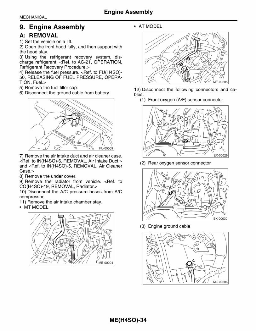
9. Engine AssemblyA: REMOVAL1) Set the vehicle on a lift.2) Open the front hood fully, and then support withthe hood stay.3) Using the refrigerant recovery system, dis-charge refrigerant. <Ref. to AC-21, OPERATION,Refrigerant Recovery Procedure.>4) Release the fuel pressure. <Ref. to FU(H4SO)-50, RELEASING OF FUEL PRESSURE, OPERA-TION, Fuel.>5) Remove the fuel filler cap.6) Disconnect the ground cable from battery.
7) Remove the air intake duct and air cleaner case.<Ref. to IN(H4SO)-6, REMOVAL, Air Intake Duct.>and <Ref. to IN(H4SO)-5, REMOVAL, Air CleanerCase.>8) Remove the under cover.9) Remove the radiator from vehicle. <Ref. toCO(H4SO)-19, REMOVAL, Radiator.>10) Disconnect the A/C pressure hoses from A/Ccompressor.11) Remove the air intake chamber stay.• MT MODEL
• AT MODEL
12) Disconnect the following connectors and ca-bles.
(1) Front oxygen (A/F) sensor connector
(2) Rear oxygen sensor connector
(3) Engine ground cable
FU-00009
ME-00204
ME-00205
EX-00029
EX-00030
ME-00206
ME(H4SO)-34

MECHANICALEngine Assembly
(4) Engine harness connectors
(5) Generator connector, terminal and A/Ccompressor connector
(6) Accelerator cable (A) and cruise control ca-ble (B) (Model with cruise control)
(7) Power steering switch connector
13) Disconnect the following hoses.(1) Brake booster vacuum hose
(2) Heater inlet outlet hose
14) Remove the power steering pump from brack-et.
(1) Remove the resonator chamber.(2) Loosen the lock bolt and slider bolt, andthen remove the front side V-belt. <Ref. toME(H4SO)-43, FRONT SIDE BELT, REMOV-AL, V-belt.>(3) Remove the pipe with bracket.
(A) Generator connector and terminal
(B) A/C compressor connector
FU-00826
ME-00208
( A )
( B )
FU-00251
(B)
(A)
FU-00878
FU-00879
ME-00330
FU-00877
ME(H4SO)-35

MECHANICALEngine Assembly
(4) Remove the bolts which install the powersteering pump bracket.
(5) Remove the power steering tank frombracket by pulling it upward.
(6) Place the power steering pump on right sidewheel apron.
15) Remove the front and center exhaust pipe.<Ref. to EX(H4SO)-6, REMOVAL, Front ExhaustPipe.>16) Remove the nuts which hold the lower side oftransmission to engine.
17) Remove the nuts which install the front cushionrubber onto front crossmember.
18) Separate the torque converter clutch from driveplate. (AT model)
(1) Lower the vehicle.(2) Remove the service hole plug.(3) Remove the bolts which hold the torqueconverter clutch to drive plate.(4) Remove other bolts while rotating the en-gine using socket wrench.
19) Remove the pitching stopper.
20) Disconnect the fuel delivery hose (A), returnhose (B) and evaporation hose (C).
CAUTION:• Disconnect the hose with its end wrappedwith cloth to prevent fuel from splashing.
FU-00139
FU-00020
FU-00140
ME-00210
ME-00211
ME-00212
ME-00213
ME(H4SO)-36

MECHANICALEngine Assembly
• Catch fuel from the hose into container.
21) Support the engine with a lifting device andwire ropes.
22) Support the transmission with a garage jack.
CAUTION:Before moving the engine away from transmis-sion, check to be sure no work has been over-looked. Doing this is very important in order to facilitate re-installation and because the trans-mission lowers under its own weight.
23) Separation of the engine and transmission.(1) Remove the starter. <Ref. to SC(H4SO)-7,REMOVAL, Starter.>
(2) Remove the bolts which hold the upper sideof transmission to engine.
24) Install the ST to torque converter clutch case.(AT model)ST 498277200 STOPPER SET
25) Remove the engine from vehicle.(1) Slightly raise the engine.(2) Raise the transmission with garage jack.(3) Move the engine horizontally until mainshaft is withdrawn from clutch cover.(4) Slowly move the engine away from enginecompartment.
NOTE:Be careful not to damage the adjacent parts orbody panels with crank pulley, oil level gauge, etc.
26) Remove the front cushion rubbers.
B: INSTALLATION1) Install the front cushion rubbers.
Tightening torque:34 N·m (3.5 kgf-m, 25.3 ft-lb)
(A) Transmission
(B) Garage jack
FU-00149
(A)
(B)
(C)
ME-00214
ME-00215
(B)
(A)
ME-00216
ST
ME-00217
ME-00214
ME(H4SO)-37

MECHANICALEngine Assembly
2) Install the engine onto transmission.(1) Position the engine in engine compartmentand align it with transmission.
NOTE:Be careful not to damage the adjacent parts orbody panels with crank pulley, oil level gauge, etc.
(2) Apply a small amount of grease to the splineof main shaft. (MT model)
3) Tighten the bolts which hold the upper side oftransmission to engine.
Tightening torque:50 N·m (5.1 kgf-m, 36.9 ft-lb)
4) Remove the lifting device and wire ropes.
5) Remove the garage jack.6) Install the pitching stopper.
Tightening torque:T1: 50 N·m (5.1 kgf-m, 37 ft-lb)T2: 58 N·m (5.9 kgf-m, 43 ft-lb)
7) Remove the ST from torque converter clutchcase. (AT model)
NOTE:Be careful not to drop the ST into torque converterclutch case when removing ST.ST 498277200 STOPPER SET8) Install the starter. <Ref. to SC(H4SO)-7, IN-STALLATION, Starter.>9) Install the torque converter clutch onto driveplate. (AT model)
(1) Tighten the bolts which hold the torque con-verter clutch to drive plate.(2) Tighten other bolts while rotating the engineby using a socket wrench.
NOTE:Be careful not to drop the bolts into torque convert-er clutch housing.
Tightening torque:25 N·m (2.5 kgf-m, 18.1 ft-lb)
(3) Clog the plug onto service hole.
ME-00214
ME-00216
ME-00214
ME-00218T2 T1
ME-00212
ME(H4SO)-38

MECHANICALEngine Assembly
10) Install the power steering pump on bracket.(1) Install the power steering tank on bracket.
(2) Install the power steering pump on bracket,and then tighten the bolts.
Tightening torque:20.1 N·m (2.05 kgf-m, 14.8 ft-lb)
(3) Tighten the bolts which install the powersteering pipe bracket, and then install the sparkplug cords.
(4) Connect the power steering switch connec-tor.
(5) Install the front side V-belt, and adjust it.<Ref. to ME(H4SO)-43, FRONT SIDE BELT, IN-STALLATION, V-belt.>(6) Install the resonator chamber.
Tightening torque:33 N·m (3.4 kgf-m, 24.6 ft-lb)
11) Tighten the nuts which hold the lower side oftransmission to engine.
Tightening torque:50 N·m (5.1 kgf-m, 36.9 ft-lb)
12) Tighten the nuts which install the front cushionrubber onto crossmember.
Tightening torque:85 N·m (8.7 kgf-m, 63 ft-lb)
NOTE:Make sure the front cushion rubber mounting bolts(A) and locator (B) are securely installed.
13) Install the front and center exhaust pipe. <Ref.to EX(H4SO)-7, INSTALLATION, Front ExhaustPipe.>
FU-00020
FU-00139
FU-00877
FU-00878
IN-00044
ME-00219
ME-00056
(A)(A) (B)(B)
ME(H4SO)-39

MECHANICALEngine Assembly
14) Connect the following hoses.(1) Fuel delivery hose, return hose and evapo-ration hose(2) Heater inlet and outlet hoses(3) Brake booster vacuum hose
15) Connect the following connectors.(1) Engine ground cables
Tightening torque:14 N·m (1.4 kgf-m, 10.1 ft-lb)(2) Engine harness connectors(3) Generator connector and terminal(4) A/C compressor connectors
16) Connect the following cables.(1) Accelerator cable(2) Cruise control cable (Model with cruise con-trol)
17) Adjust each connected cable.18) Install the air cleaner case stay.
Tightening torque:16 N·m (1.6 kgf-m, 11.6 ft-lb)
19) Install the A/C pressure hoses.<Ref. to AC-36, INSTALLATION, Hose and Tube.>20) Install the radiator to vehicle. <Ref. toCO(H4SO)-20, INSTALLATION, Radiator.>21) Install the air intake duct and air cleaner case.<Ref. to IN(H4SO)-6, INSTALLATION, Air IntakeDuct.> and <Ref. to IN(H4SO)-5, INSTALLATION,Air Cleaner Case.>22) Install the under cover.23) Install battery in the vehicle, and then connectthe cables.24) Fill engine coolant.<Ref. to CO(H4SO)-13, FILLING OF ENGINECOOLANT, REPLACEMENT, Engine Coolant.>25) Check the ATF level and correct if necessary.(AT model)<Ref. to 4AT-31, INSPECTION, Automatic Trans-mission Fluid.>26) Charge the A/C system with refrigerant.<Ref. to AC-22, OPERATION, Refrigerant Charg-ing Procedure.>27) Remove the front hood stay, and then close thefront hood.28) Take off the vehicle from lift arms.
C: INSPECTION1) Make sure the pipes and hoses are installed cor-rectly.2) Make sure the engine coolant and ATF are atspecified levels.
ME(H4SO)-40
MECHANICALEngine Mounting
10.Engine MountingA: REMOVAL1) Remove the engine assembly. <Ref. toME(H4SO)-34, REMOVAL, Engine Assembly.>2) Remove the engine mounting from engine as-sembly.
B: INSTALLATIONInstall in the reverse order of removal.
Tightening torque:Engine mounting;
35 N·m (3.6 kgf-m, 25.8 ft-lb)
C: INSPECTIONMake sure there are no cracks or other damage.
ME(H4SO)-41

MECHANICALPreparation for Overhaul
11.Preparation for OverhaulA: PROCEDURE1) After removing the engine from body, secure it inthe ST shown below.ST1 498457000 ENGINE STAND ADAPTER
RHST2 498457100 ENGINE STAND ADAPTER
LHST3 499817100 ENGINE STAND
2) In this section the procedures described undereach index are all connected and stated in order. Itwill be the complete procedure for overhauling ofthe engine itself when you go through all steps inthe process.Therefore, in this section, to conduct the particularprocedure within the flow of a section, you need togo back and conduct the procedure described pre-viously in order to do that particular procedure.
ME-00221ST2
ST1ST3
ME(H4SO)-42

MECHANICALV-belt
12.V-beltA: REMOVAL1. FRONT SIDE BELT
NOTE:Perform the following procedures 1) to 4) with theengine installed to body.1) Remove the V-belt cover.
2) Loosen the lock bolt (A).3) Loosen the slider bolt (B).4) Remove the front side belt (C).
2. REAR SIDE BELT1) Loosen the lock nut (A).2) Loosen the slider bolt (B).
3) Remove the rear side belt.
4) Remove the belt tensioner.
B: INSTALLATIONNOTE:Wipe off any oil or water on the belt and pulley.
1. FRONT SIDE BELT1) Install a V-belt (C), and tighten the slider bolt soas to obtain the specified belt tension. <Ref. toME(H4SO)-44, INSPECTION, V-belt.>2) Tighten the lock bolt (A).3) Tighten the slider bolt (B).
Tightening torque:Lock bolt (A):
25 N·m (2.5 kgf-m, 18.1 ft-lb)Slider bolt (B):
8 N·m (0.8 kgf-m, 5.9 ft-lb)
2. REAR SIDE BELT1) Remove the A/C belt tensioner.2) Install a V-belt, and tighten the slider bolt (B) soas to obtain the specified belt tension.<Ref. to ME(H4SO)-44, INSPECTION, V-belt.>
ME-00222
ME-00223
(B)(C)
(A)
ME-00224
(A)
(B)
ME-00225
(A)
(C)
(B)
ME-00059
ME(H4SO)-43

MECHANICALV-belt
3) Tighten the lock nut (A).
Tightening torque:Lock nut (A):
22.6 N·m (2.3 kgf-m, 16.6 ft-lb)
C: INSPECTION1) Replace the belts, if cracks, fraying or wear isfound.2) Check the V-belt tension and adjust it if neces-sary by changing the generator installing positionand idler pulley installing position.
Belt tension (with belt tension gauge)
(A)When installing new parts:
618 — 755 N (63 — 77 kgf, 139 — 170 lb)At inspection:
490 — 640 N (50 — 65 kgf, 110 — 144 lb)
(B)When installing new parts:
740 — 880 N (75 — 90 kgf, 166 — 198 lb)At inspection:
350 — 450 N (36 — 46 kgf, 78 — 101 lb)
Belt tension (without belt tension gauge)
(A)When installing new parts:
7 — 9 mm (0.276 — 0.354 in)At inspection:
9 — 11 mm (0.354 — 0.433 in)
(B)When installing new parts:
7.5 — 8.5 mm (0.295 — 0.335 in)At inspection:
9.0 — 10.0 mm (0.354 — 0.394 in)
(A) Front side belt
(B) Rear side belt
C/P Crank pulley
GEN Generator
P/S Power steering oil pump pulley
A/C A/C compressor pulley
I/P Idler pulley
(A)
(B)
ME-00060
C/P
P/S A/CGEN
(A)
(B)
I/P
PM-00154
C/P Crank pulley
GEN Generator
P/S Power steering oil pump pulley
A/C A/C compressor pulley
I/P Idler pulley
ME-00062
P/S
C/P
GEN
I/P
A/C
98 N (10 kgf, 22 lb)
(A) (B)
ME(H4SO)-44