2003+ protechtm lcd series owner’s manual protechtm lcd series owner’s manual. ... circulatory...
TRANSCRIPT

2003+ ProTechTM LCD Series Owner’s Manual
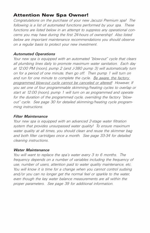
Attention New Spa Owner!Congratulations on the purchase of your new Jacuzzi Premium spa! Thefollowing is a list of automated functions performed by your spa. Thesefunctions are listed below in an attempt to suppress any operational con-cerns you may have during the first 24-hours of ownership! Also listedbelow are important maintenance recommendations you should observeon a regular basis to protect your new investment.
Automated OperationsYour new spa is equipped with an automated “blow-out” cycle that clearsall plumbing lines daily to promote maximum water sanitation. Each dayat 12:00 PM (noon), pump 2 (and J-380 pump 3) will automatically turnon for a period of one minute, then go off. Then pump 1 will turn onand run for one minute to complete the cycle. Be aware, the factory programmed blow-out cycle cannot be canceled or altered! However, Ifyou set one of four programmable skimming/heating cycles to overlap orstart at 12:00 (noon), pump 1 will turn on as programmed and operatefor the duration of the programmed cycle, overriding the factory “blow-out” cycle. See page 30 for detailed skimming/heating cycle program-ming instructions.
Filter MaintenanceYour new spa is equipped with an advanced 2-stage water filtration system that provides unsurpassed water quality! To ensure maximumwater quality at all times, you should clean and reuse the skimmer bagand both filter cartridges once a month. See page 33-34 for detailedcleaning instructions.
Water MaintenanceYou will want to replace the spa’s water every 3 to 6 months. The frequency depends on a number of variables including the frequency ofuse, number of users, attention paid to water quality maintenance, etc.You will know it is time for a change when you cannot control sudsingand/or you can no longer get the normal feel or sparkle to the water,even though the key water balance measurements are all within theproper parameters. See page 39 for additional information.
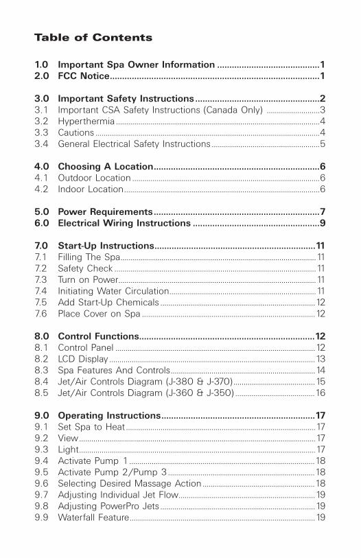
Table of Contents
1.0 Important Spa Owner Information ..........................................12.0 FCC Notice......................................................................................1
3.0 Important Safety Instructions ...................................................23.1 Important CSA Safety Instructions (Canada Only) ..........................33.2 Hyperthermia ....................................................................................................43.3 Cautions ..............................................................................................................43.4 General Electrical Safety Instructions .....................................................5
4.0 Choosing A Location....................................................................64.1 Outdoor Location ............................................................................................64.2 Indoor Location................................................................................................6
5.0 Power Requirements....................................................................76.0 Electrical Wiring Instructions ....................................................9
7.0 Start-Up Instructions..................................................................117.1 Filling The Spa................................................................................................117.2 Safety Check ...................................................................................................117.3 Turn on Power.................................................................................................117.4 Initiating Water Circulation........................................................................117.5 Add Start-Up Chemicals ............................................................................127.6 Place Cover on Spa .....................................................................................12
8.0 Control Functions........................................................................128.1 Control Panel ..................................................................................................128.2 LCD Display .....................................................................................................138.3 Spa Features And Controls.......................................................................148.4 Jet/Air Controls Diagram (J-380 & J-370)........................................158.5 Jet/Air Controls Diagram (J-360 & J-350) .......................................16
9.0 Operating Instructions...............................................................179.1 Set Spa to Heat .............................................................................................179.2 View....................................................................................................................179.3 Light....................................................................................................................179.4 Activate Pump 1...........................................................................................189.5 Activate Pump 2/Pump 3........................................................................189.6 Selecting Desired Massage Action .......................................................189.7 Adjusting Individual Jet Flow...................................................................199.8 Adjusting PowerPro Jets ............................................................................199.9 Waterfall Feature...........................................................................................19

9.10 Air Controls......................................................................................................199.11 Optional Jacuzzi Premium Audio System ..........................................19
10.0 Automatic Filtration Cycles .....................................................2810.1 Standard Skimming/Heating Mode .....................................................2810.2 Economy Skimming/Heating Mode.....................................................2810.3 Selecting Standard or Economy Skimming/Heating Mode ......2810.4 Preset Skimming/Heating Cycles ..........................................................2910.5 Clean-Up Cycle ..............................................................................................29
11.0 Programming Instructions .......................................................3011.1 Adjusting Time of Day ...............................................................................3011.2 Changing Skimming/Heating Cycles ..................................................3011.3 Programming The Filter Change Reminder.......................................3111.4 Programming Circulation Pump Run Time ........................................3111.5 Locking Skimming/Heating Cycles ......................................................3211.6 Panel Lock .......................................................................................................3211.7 Temperature Setting Lock.........................................................................33
12.0 Spa Maintenance .......................................................................3312.1 Cleaning The Filters ....................................................................................3312.2 Draining and Refilling .................................................................................3512.3 Cleaning The Spa Interior.........................................................................3612.4 Pillow Care ......................................................................................................3612.5 Maintaining The Cover ...............................................................................3712.6 Maintaining The Wood Cabinet..............................................................3712.7 Maintaining The Optional Synthetic Cabinet ....................................3712.8 Winterizing ......................................................................................................3812.9 Restarting Your Spa in Cold Weather .................................................38
13.0 Water Quality Maintenance.....................................................3913.1 pH Control .......................................................................................................3913.2 Sanitizing..........................................................................................................3913.3 Optional CD Ozone Water Maintenance System...........................4013.4 Summer Logic ...............................................................................................40
14.0 Troubleshooting - Display Messages.....................................4115.0 Troubleshooting - Procedures .................................................4316.0 Wiring Diagram (60Hz J-350/J-360/J-370 Models) .........4517.0 Wiring Diagram (60Hz J-380 Model)....................................4618.0 Wiring Diagram (50Hz J-350/J-360/J-370 Models) .........4719.0 Wiring Diagram (50Hz J-380 Model) ...................................4820.0 Typical Spa Wiring Diagrams A-B (60Hz Models) .............49
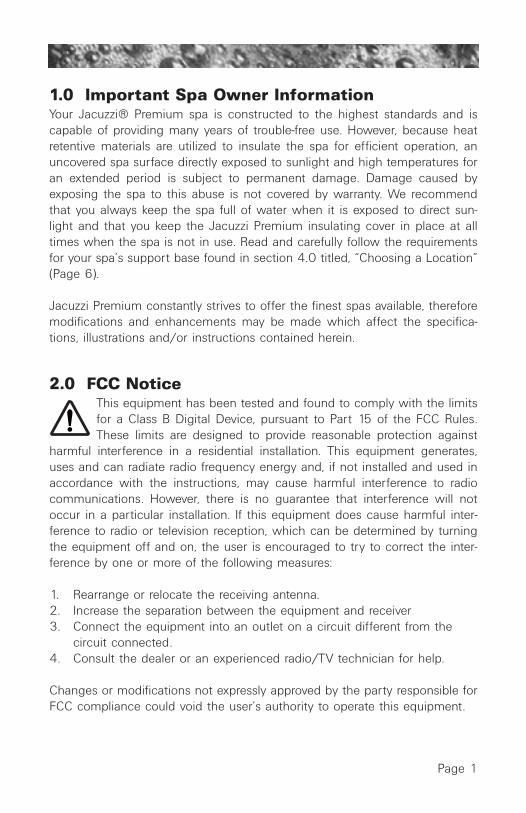
1.0 Important Spa Owner InformationYour Jacuzzi® Premium spa is constructed to the highest standards and iscapable of providing many years of trouble-free use. However, because heatretentive materials are utilized to insulate the spa for efficient operation, anuncovered spa surface directly exposed to sunlight and high temperatures foran extended period is subject to permanent damage. Damage caused byexposing the spa to this abuse is not covered by warranty. We recommendthat you always keep the spa full of water when it is exposed to direct sun-light and that you keep the Jacuzzi Premium insulating cover in place at alltimes when the spa is not in use. Read and carefully follow the requirementsfor your spa’s support base found in section 4.0 titled, “Choosing a Location”(Page 6).
Jacuzzi Premium constantly strives to offer the finest spas available, thereforemodifications and enhancements may be made which affect the specifica-tions, illustrations and/or instructions contained herein.
2.0 FCC NoticeThis equipment has been tested and found to comply with the limitsfor a Class B Digital Device, pursuant to Part 15 of the FCC Rules.These limits are designed to provide reasonable protection against
harmful interference in a residential installation. This equipment generates,uses and can radiate radio frequency energy and, if not installed and used inaccordance with the instructions, may cause harmful interference to radiocommunications. However, there is no guarantee that interference will notoccur in a particular installation. If this equipment does cause harmful inter-ference to radio or television reception, which can be determined by turningthe equipment off and on, the user is encouraged to try to correct the inter-ference by one or more of the following measures:
1. Rearrange or relocate the receiving antenna.2. Increase the separation between the equipment and receiver3. Connect the equipment into an outlet on a circuit different from the
circuit connected.4. Consult the dealer or an experienced radio/TV technician for help.
Changes or modifications not expressly approved by the party responsible forFCC compliance could void the user’s authority to operate this equipment.
Page 1

3.0 IMPORTANT SAFETY INSTRUCTIONS
When installing and using this electrical equipment, basic safety pre-cautions should always be followed, including:
1. READ AND FOLLOW ALL INSTRUCTIONS BEFORE OPERATING THE SPA!
2. WARNING: To reduce the risk of injury, do not permit children to use thisproduct unless they are closely supervised at all times.
3. WARNING: A grounding wire connector is provided on this unit to con-nect a minimum No. 8 AWG (8.4mm2) solid copper conductor betweenthis unit and any metal equipment, metal enclosures of electrical equip-ment, metal water pipe, or conduit within 5 feet (1.5m) of the unit.
4. DANGER: Risk of Accidental Drowning. Extreme caution must be exer-cised to prevent unauthorized access by children. To avoid accidents,ensure that children cannot use this spa unless they are supervised at alltimes.
5. DANGER: Risk of Injury. The suction fittings in this spa are sized to matchthe specific water flow created by the pump. Should the need arise toreplace the suction fittings or the pump, be sure that the flow rates arecompatible. Never operate the spa if the suction fittings are broken ormissing. Never replace a suction fitting with one rated less than the flowrate marked on the original suction fitting.
6. DANGER: Risk of Electric Shock. Install at least 5 feet (1.5m) from all metalsurfaces. As an alternative, a spa may be installed within 5 feet of metalsurfaces if each metal surface is permanently connected (bonded) by aminimum No. 8 AWG (8.4mm2) solid copper conductor attached to thewire connector on the grounding lug, inside the equipment compartmenton the equipment box.
7. DANGER: Risk of Electric Shock. Do not permit any electrical appliance,such as a light, telephone, radio, television, etc. within 5 feet (1.5m) of aspa, unless such appliances are built-in by the manufacturer.
8. ELECTRICAL SUPPLY: The electrical supply for this product must includea suitably rated switch or circuit breaker to open all ungrounded supplyconductors to comply with section 422-20 of the National Electrical Code,ANSI/NFPA 70. The disconnect must be readily accessible and visible tothe spa occupant but installed at least 5 feet (1.5m) from the spa water.
9. WARNING: To Reduce the Risk of Injury:A. The water in a spa should never exceed 104 °F (40 °C). Water tempera-
tures between 100 °F (38 °C) and 104 °F (40°C) are considered safe for a healthy adult. Lower water temperatures are recommended for youngchildren and when spa use exceeds 10 minutes.
Page 2

B. Since excessive water temperatures have a high potential for causing fetaldamage during the early months of pregnancy, pregnant or possibly preg-nant women should limit spa water temperatures to 100 °F (38 °C). Ifpregnant, please consult your physician before using a spa.
C. Before entering the spa, the user should measure the water temperaturewith an accurate thermometer since the tolerance of water temperature-regulating devices may vary as much as ±5 °F (±2 °C).
D. The use of alcohol, drugs, or medication before or during spa use maylead to unconsciousness with the possibility of drowning. Persons usingmedication should consult a physician before using a spa since somemedication may induce drowsiness, while other medication may affectheart rate, blood pressure, and circulation.
E. Persons suffering from obesity or a medical history of heart disease, lowor high blood pressure, circulatory system problems, or diabetes shouldconsult a physician before using a spa.
3.1 IMPORTANT CSA SAFETY INSTRUCTIONS (CANADA ONLY)When using this electrical equipment, basic safety precautionsshould always be followed, including the following:
1. READ AND FOLLOW ALL INSTRUCTIONS.2. A green colored terminal or a terminal marked G, Gr, Ground, Grounding
or the symbol* is located inside the supply terminal box or compart-ment. To reduce the risk of electric shock, this terminal must be con-nected to the grounding means provided in the electric supply servicepanel with a continuous copper wire equivalent in size to the circuitconductors that supply this equipment (*IEC Publication 417, Symbol5019).
3. At least two lugs marked “Bonding Lugs” are provided on the external surface or on the inside of the supply terminal box/compartment. To reduce the risk of electric shock, connect the local common bonding gridin the area of the spa to these terminals with an insulated or bare copper conductor not smaller than No. 6 AWG (10mm2).
4. All field-installed metal components such as rails, ladders, drains or othersimilar hardware within 10 feet (3m) of the spa shall be bonded to the equipment grounding buss with copper conductors not smaller thanNo. 6 AWG (10mm2).
5. Save These Instructions:A. WARNING: Children should not use spas without adult supervision.B. WARNING: Do not use spas unless all suction guards are installed to
prevent body and hair entrapment.
Page 3

C. WARNING: People with infectious diseases should not use a spa.D. WARNING: To avoid injury, exercise care when entering or exiting the
spa.E. WARNING: Do not use drugs or alcohol before or during the use of a
spa to avoid unconsciousness and possible drowning.F. WARNING: Pregnant or possibly pregnant women should consult a
physician before using a spa.G. WARNING: Water temperature in excess of 38 °C (104 °F) may be
injurious to your health.H. WARNING: Before entering the spa, measure the water temperature
with an accurate thermometer.I. WARNING: Do not use a spa immediately following strenuous exercise.J. WARNING: Prolonged immersion in a spa may be injurious to your
health.K. WARNING: Do not permit electric appliances (such as light, telephone,
radio, television, etc.) within 5 feet (1.5m) of this spa unless factory installed.
L. CAUTION: Maintain water chemistry in accordance with manufacturer’s instructions.
M. WARNING: The use of alcohol or drugs can greatly increase the risk of fatal hyperthermia in spas.
3.2 HYPERTHERMIAProlonged immersion in hot water may induce hyperthermia. A description ofthe causes, symptoms, and effects of hyperthermia are as follows:
Hyperthermia occurs when the internal temperature of the body reaches alevel several degrees above the normal body temperature of 98.6 °F (37 °C).The symptoms of hyperthermia include drowsiness, lethargy, and an increasein the internal temperature of the body. The effects of hyperthermia include:
A Unawareness of impending hazard;B. Failure to perceive heat;C. Failure to recognize the need to exit spa;D. Physical inability to exit spa;E. Fetal damage in pregnant women; andF. Unconsciousness and danger of drowning.
3.3 CAUTIONS1. Persons suffering from heart disease, diabetes, high or low blood pres-
sure, and any condition requiring medical treatment, pregnant women,the elderly, or infants should consult with a physician before using a spa.
Page 4

2. The Consumer Products Safety Commission has stated that the water temperature in a spa should not exceed 104 °F (40 °C). Immersion inwater in excess of 104 °F (40 °C) can be hazardous to your health.
3. Observe a reasonable time limit when using the spa. Long exposures athigher temperatures can cause high body temperature. Symptoms mayinclude dizziness, nausea, fainting, drowsiness, and reduced awareness.These effects could possibly result in drowning.
4. Do not use the spa under the influence of alcohol, narcotics, or otherdrugs. Use of the spa under these conditions may lead to serious conse-quences.
5. Always test the spa water temperature before entering the spa. Enter andexit the spa slowly. Wet surfaces can be very slippery.
6. Never bring any electrical appliances into or near the spa. Never operateany electrical appliances from inside the spa or when you are wet unlesssuch appliances are built-in by the manufacturer.
7. Proper chemical maintenance of spa water is necessary to maintain safe water and prevent possible damage to spa components.
8. Use the straps and clip tie downs to secure the cover when not in use.This will help to discourage unsupervised children from entering the spaand keep the spa cover secure in high-wind conditions. There is no rep-resentation that the cover, clip tie-downs, or actual locks will preventaccess to the spa.
3.4 GENERAL ELECTRICAL SAFETY INSTRUCTIONSYour new Jacuzzi Premium spa is equipped with a "state-of-the-art" equip-ment system. It contains the most advanced safety and self-protective equip-ment in the industry. Nonetheless, this spa must be installed properly toinsure dependable usage. Please contact your dealer or local buildingdepartment should you have any questions regarding your installation.
Proper grounding is extremely important. Jacuzzi Premium spas areequipped with a current collector system. A pressure wire connector is pro-vided on the surface of the control box, located outside the equipment door(Figure B, Page 10) to permit connection of a bonding wire between thispoint and any ground metal equipment, metal water pipe or conduit within5 feet (1.5m) of the spa, or copper clad grounding rod buried within 5 feet(1.5m) of the spa. Bonding wire must be at least No. 8 AWG (8.4mm2)solid copper wire. This is a most important safety assurance feature. Beforeinstalling this spa, check with the local building department to insure instal-lation conforms to local building codes.
Page 5

4.0 Choosing A LocationIMPORTANT: Because of the combined weight of the spa, water andusers, it is extremely important that the base upon which the sparests be smooth, flat, level and capable of uniformly supporting this
weight, without shifting or settling, for the entire time the spa is in place. Ifthe spa is placed on a surface which does not meet these requirements, dam-age to the skirt and/or the spa shell may result. Damage caused by improp-er support is not covered under warranty. It is the responsibility of the spaowner to assure the integrity of the support at all times.
We recommend a poured, reinforced concrete slab with a minimum thicknessof 4 inches (10cm). Wood decking is also acceptable provided it is con-structed so that it meets the requirements outlined above. The spa must beinstalled in such a manner as to provide drainage away from the spa. Placingthe spa in a depression without provisions for proper drainage could allowrain, overflow and other casual water to flood the equipment and create a wetcondition in which it would sit. For spas which will be recessed into a floor ordeck, install so as to permit access to the equipment, either from above orbelow, for servicing. Make certain that there are no obstructions which wouldprevent removal of the cabinet side panels and access to the jets components,especially on the side with the equipment bay doors.
4.1 Outdoor LocationIn selecting the ideal outdoor location for your spa, we suggest that you takeinto consideration:1. The proximity to changing area and shelter (especially in colder weather).2. The pathway to and from your spa (this should be free of debris so that
dirt and leaves are not easily tracked into the spa).3. The closeness to trees and shrubbery (remember that leaves and birds
could create extra work in keeping the spa clean).4. A sheltered environment (less wind and weather exposure can result in
lowered operation and maintenance costs).5. The overall enhancement of your environment. It is preferable not to place
the spa under an unguttered roof overhang since run-off water will shorten the life expectancy of the spa cover.
4.2 Indoor LocationFor indoor installations, be certain to make provisions for proper ventilation.When the spa is in use, considerable amounts of moisture will escape. Thiscan damage certain surfaces over time. If you have any questions regardingthe placement or installation of your spa, consult your authorized JacuzziPremium dealer.Page 6
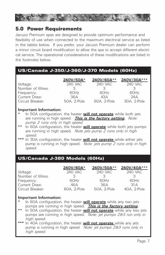
US/Canada J-350/J-360/J-370 Models (60Hz)
240V/50A* 240V/60A** 240V/30A***Voltage: 240 VAC 240 VAC 240 VACNumber of Wires: 3 3 3Frequency: 60Hz 60Hz 60HzCurrent Draw: 36A 43A 24ACircuit Breaker: 50A, 2-Pole 60A, 2-Pole 30A, 2-Pole
Important Information:* In 50A configuration, the heater will not operate while both jets
are running in high speed. This is the factory setting. Note: pump 2 runs only in high speed.
** In 60A configuration, the heater will operate while both jets pumps are running in high speed. Note jets pump 2 runs only in high speed.
*** In 30A configuration, the heater will not operate while either jets pump is running in high speed. Note: jets pump 2 runs only in high speed.
US/Canada J-380 Models (60Hz)
240V/60A* 240V/50A** 240V/40A***Voltage: 240 VAC 240 VAC 240 VACNumber of Wires: 3 3 3Frequency: 60Hz 60Hz 60HzCurrent Draw: 46A 36A 31ACircuit Breaker: 60A, 2-Pole 50A, 2-Pole 40A, 2-Pole
Important Information:* In 60A configuration, the heater will operate while any two jets
pumps are running in high speed. This is the factory setting.** In 50A configuration, the heater will not operate while any two jets
pumps are running in high speed. Note: jet pumps 2&3 run only in high speed.
*** In 40A configuration, the heater will not operate while any jets pump is running in high speed. Note: jet pumps 2&3 runs only in high speed.
5.0 Power RequirementsJacuzzi Premium spas are designed to provide optimum performance and flexibility of use when connected to the maximum electrical service as listedin the tables below. If you prefer, your Jacuzzi Premium dealer can performa minor circuit board modification to allow the spa to accept different electri-cal service. The operational considerations of these modifications are listed inthe footnotes below.
Page 7

Export J-380 Models (50Hz)
230V/40A* 230V/35A**Voltage: 230 VAC 230 VACNumber of Wires 3 3Frequency: 50Hz 50HzCurrent Draw: 32A 26ACircuit Breaker: 40A 35A
Important Information: * In 40A configuration, the heater will operate while any two jets
pumps are running in high speed. Note: jet pumps 2&3 run only in high speed. This is the factory setting.
** In 35A configuration, the heater will not operate while any two jets pumps are running in high speed. Note: jet pumps 2&3 run only in high speed.
All export models can be adapted to use higher amperage circuits whenavailable. Please contact your dealer for details. The electrical supply forthis product must comply with local electrical regulations.
Export J-350/J-360/J-370 Models (50Hz)
230V/20A* 230V/30A** 230V/40A***Voltage: 230 VAC 230 VAC 230 VACNumber of Wires 3 3 3Frequency: 50Hz 50Hz 50HzCurrent Draw: 15A 23A 29ACircuit Breaker: 20A 30A 40A
Important Information: * In 20A configuration, the heater will not operate while either jets
pump is running in high speed. Note: jets pump 2 runs only in high speed. This is the factory setting.
** In 30A configuration, the heater will not operate when both jets pumps are running in high speed. Note jets pump 2 runs only in high speed.
*** In 40A configuration, the heater will operate while both jets pumps are running in high speed.
All export models can be adapted to use higher amperage circuits whenavailable. Please contact your dealer for details. The electrical supply forthis product must comply with local electrical regulations.
Page 8

Page 9
6.0 Electrical Wiring Instructions
IMPORTANT NOTICE: The electrical wiring of this spa must meetthe requirements of the National Electrical Code (NEC) and anyapplicable state or local codes. The electrical circuit must beinstalled by a qualified electrician and approved by a local build-ing/electrical inspection authority.
1. This spa must be permanently connected (hard-wired) to the power supply. No plug-in connections or extension cords are to be used inconjunction with the operation of this spa. Supplying power to the spa which is not in accordance with these instructions will void both the independent testing agency listing and the manufacturer’s warranty.
2. The power supplied to this spa must be a dedicated circuit with no other appliances or lights sharing the power provided by the circuit.
3. To determine the current and voltage and wire size required, refer to section 5.0 “Power Requirements” (Page 7-8).
• Wire size must be appropriate per NEC and/or local codes.• We recommend type THHN wire.• All wiring must be copper to ensure proper connections. Do not use
aluminum wire.• When using wire larger than #6 (10mm2), add a junction box near the
spa and reduce to short lengths of #6 (10mm2) wire to connect to spa.4. The electrical supply for this product must include a suitably rated switch
or circuit breaker to open all ungrounded supply conductors to comply with Section 422-20 of the National Electrical Code, ANSI/NFPA 70. Thedisconnecting means must be readily accessible to the spa’s occupant but installed at least 5 feet (1.5m) from spa water.
5. The electrical circuit supplied for the spa must include a suitable ground fault circuit interruptor (GFCI) as required by NEC Article 680-42.
6. To gain access to the spa’s power terminal block, remove the screws securing the panel under the controls. Then remove the four control boxdoor screws and door (Figure B, Page 10).
7. Select the power supply inlet you want to use (Figure A, Page 10) and remove the short cabinet panel from the front of the spa to allow you tofeed the cable through to the control box. Install the cable with connec-tor through the large opening provided in the bottom of the control box.
8. Connect wires, color to color, on terminal blocks TB1 and TB3 (FiguresC-D, Page 10). TIGHTEN SECURELY! All wires must be hooked up secure-ly or damage could result.
9. Install control box door and screws and reinstall the cabinet side panels.

Page 10
BLUE
BLUE
BROWN
BROWN
1
2
US/Canada J-350 / J-360 / J-370 / J-380 �Models: 240 VAC, 3-Wire Connection (60Hz)
Figure-D TB1
All Export J-350 / J-360 / J-370 / J-380 �Models: 230 VAC, 3-Wire (50Hz)
to Circuit Board
BLK
RED
Pow
er In
RED
RED
BLK
BLK
1
2
Figure-C TB1
to Circuit Board
Pow
er In
Figure-B - Control Box
Green
TB3
Green
TB3
104
37
3
1
2
2
2
1. Terminal Block2. Bonding Lug3. Grounding Terminal
TB1
Figure-A �Equipment Area
1. Control Box2. Power Supply Entrance(s)3. 2-Speed Pump #14. Heater5. Spa Drain Valve6. Pump Drain Plug(s)
7. 1-Speed Pump #28. Circulation Pump9. Optional CD Ozonator (Purchased Separately)10.Optional Mazzei Injector (Required for CD Ozonator
Use - Purchased Separately)
1
Flow
Note: Pump Locations Vary by Model
Circulation Pump�Behind Load Box
8
56 6
9

7.0 Start-Up InstructionsCongratulations! You are now all set to get your new spa ready to use. Simplyfollow this step-by-step procedure and, before long, you will be enjoying yourfirst glorious experience in your Jacuzzi Premium spa. For best results, readeach step in its entirety before proceeding with that step.
7.1 Filling the SpaClear all debris from the spa. Although the spa shell has been polished at the factory, you may want to treat it with a specially formulated spa cleaner and wax available from your dealer prior to filling the first time.
Remove the filter cover, then remove and clean the strainer bag and both filter cartridges as outlined in section 12.1 (Page 33-35). Place the end of your garden hose into the exposed pump #1 filter wall fitting without a mesh grill. Fill the spa half way, then place end of your garden hose into the circulation pump filter wall fitting with the mesh grill. Continue filling spa until the water level is 1 inch below the lowest pillow and and above all jets. Do not over fill. Never fill with water from a water softener.
If your water is extremely “hard”, it is preferable to fill half-way with hardwater and the rest of the way with softened water. Or, you may fill entirely with hard water if you use a special water additive available from yourJacuzzi Premium dealer. Always refill spa through both filter wall fittings to purge trapped air from pump intakes. Failure to do so may cause air to be trapped in either pump #1 or the circulation pump’s intake (air lock), preventing either pump from circulating water. After filling, make sure both filters are installed properly before applying power to the spa. Referto section 12.1 (Page 33-35) “Cleaning the Filters” for specific cleaningand installation instructions.
7.2 Safety CheckOpen the wood cabinet access panel and check all pump unions to make surethey are hand tight. Loosening can occur during shipping and handling.
7.3 Turn on PowerTurn on power to spa at the home’s circuit breaker. The heater and circulationpump will automatically activate. If the control panel LCD flashes water tem-perature and “COOL” or “ICE”, the pump 1 will also activate in low speed. Ifthis occurs, refer to page 41-42 for additional information.
7.4 Initiating Water CirculationDepress the JETS 1 sensor pad on the control panel twice toactivate pump #1 in high speed and initiate maximum waterflow to certain jets.
Page 11
7.5 Add Start-Up ChemicalsAdd the spa water chemicals as recommended by your Jacuzzi PremiumDealer. Refer to section 13.0 (Page 39) for general guidance.
7.6 Place Cover On SpaKeeping the insulating cover in place anytime the spa is not in use willreduce the time required for heating, thereby minimizing operating costs.The time required for initial heat-up will vary depending on the starting watertemperature and the capacity of your spa. Smaller spas heat at a rate ofapproximately 8 to 10 degrees per hour; larger spas heat at about 4 to 6degrees per hour.
WARNING: RISK OF INJURY. Always check water temperature carefully before entering spa.
8.0 Control Functions
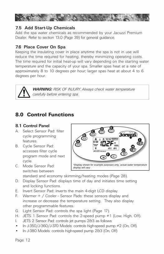
8.1 Control PanelA. Select Sensor Pad: filter
cycle programming features.
B. Cycle Sensor Pad: accesses filter cycle program mode and next cycle.
C. Mode Sensor Pad: switches between standard and economy skimming/heating modes (Page 28).
D. Display Sensor Pad: displays time of day and initiates time setting and locking functions.
E. Invert Sensor Pad: inverts the main 4-digit LCD display.F. Warmer + / Cooler - Sensor Pads: these sensors display and
increase or decrease the temperature setting. They also display other programmable features.
G. Light Sensor Pad: controls the spa light (Page 17).H. JETS 1 Sensor Pad: controls the 2-speed pump #1 (Low, High, Off).I. JETS 2 Sensor Pad: controls jet pumps 2&3 as follows:• In J-350/J-360/J-370 Models: controls high-speed pump #2 (On, Off).• In J-380 Models: controls high-speed pump 2&3 (On, Off)
Page 12
A
BC
D E
GH
I
*Display shown for example purposes only, actual water temperature display will vary
F
ChangeFilter

8.2 LCD Display
A. Lock Symbol indicates panel, set temperature, or filter cycle programming is locked.
B. Heat Symbol: indicates heater is on (Sec. 9.1, Page 17).
C. Ozone Symbol indicates the optional CD Ozonator is on Sec. 13.3,Page 40).
D. General Indicators: show which skimming/heating cycle is in progress or display selected skimming/heating cycle programmingfeatures (Sec. 11.2, Page 30).
E. Set Indicators: these characters identify what is being shown on the main 4-digit display.
F. Indicates programmed filter cleaning interval has elapsed (Sec. 11.3 Page 31).
G. Light Symbol: indicates spa light is on.
H. JETS 1 Symbol indicates 2-speed pump #1 is on. The symbol changes according to speed selected and flashes during an automatic operation.
I. JETS 2 Symbol indicates the following:• On J-350, J-360, J-370 models, this symbol indicates high-speed
pump #2 is on. • On J-380 models, this symbol indicates either high-speed pump
#2 and/or pump #3 are on.
J. Mode Annunciators: these characters identify which skimming/ heating mode is currently selected (Page 28).
Page 13
A B C
IHG
F
E
D
JCHANGEFILTER

1
8
9
10
16
11
11
2
2
2
6
3
4 7
17
17
13
18
56
6
14
12
5
15
Page 14
1. Control Panel2. Air Controls3. Filter/Skimmer Bag
Cover4. Diverter Valve #25. Maxx PowerPro Jets6. PowerPro Jets/Mini-
PowerPro Jets7. Diverter Valve #18. Remote Control Panel9. Therapy Seat10. Spa Light
8.3 Spa Features And Controls
11. Vertical Jets (Foot Jets)12. Footwell Suction Fittings and
Filters. Filters protect pump 2(and J-380 pump 3) plumbingnetwork from debris buildup.
13. Waterfall Feature14. Mini PowerPro Jets (Calf Jets)15. Micro PowerPro Jets (Wrist Jets)16. Heater Return Fitting17. Optional Audio System Speakers18. Optional Audio System Receiver
J-370 model illustrated - Location of Features Varies by Model

Page 15
8.4 Jet/Air Controls Diagram (J-380 & J-370)
Air Control OperationDepress Air Controls A-E to Open or
Close Air Inlet to Designated Jet Groups.
Air Control OperationDepress Air Controls A-E to Open or
Close Air Inlet to Designated Jet Groups.
Page 16
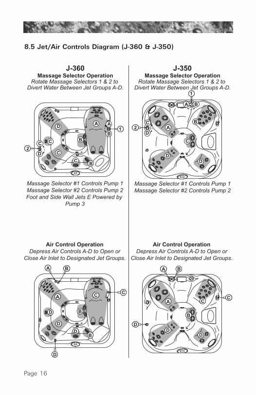
8.5 Jet/Air Controls Diagram (J-360 & J-350)
Air Control OperationDepress Air Controls A-D to Open or
Close Air Inlet to Designated Jet Groups.
Air Control OperationDepress Air Controls A-D to Open or
Close Air Inlet to Designated Jet Groups.

Page 17
9.0 Operating InstructionsYour Jacuzzi Premium spa has a touch-sensitive control panel, diverter valves,and air control knobs located on the top rim of the spa (Page 14). These con-trols let you operate many of the special functions of your Jacuzzi Premiumspa. By familiarizing yourself with the following information, you will be ableto gain the full benefit afforded by the various functions of your spa.
9.1 Set Spa To HeatTo warm spa water, follow these steps:1. The LCD display on the control panel displays the actual
temperature of the spa water. Press either the WARMER ( + ) or COOLER ( - ) sensor pad once to display the “settemperature” for 5 seconds. If you want the water to heatto a different temperature, simply press WARMER ( + ) orCOOLER ( - ) within 5 seconds. The set temperature advances ordecreases by one degree each time one of these sensor pads is pressed.
2. The heater will turn off when the temperature corresponding to the thermostat setting is achieved.
Important Heater Details:• The maximum temperature for which the spa can be set is 104 °F
(40 °C) and the minimum is 80 °F (27 °C).• If spa is powered by the minimum required amp service (Page 7-8)
turn off all high speed pumps to operate heater. Note: jets Pump 2 and J-380 Pump 3 run only in high speed.
• Setting the thermostat at maximum will not accelerate the heating process. This will only result in a higher ultimate temperature.
• The heater operates until the water reaches the programmed “set temperature”, then turns off. The heater will reactivate after the water cools to approximately 1.5° below the “set temperature.”
9.2 ViewPressing this sensor pad inverts the main four-digit display onthe command center’s LCD screen to allow easy reading fromeither inside or outside the spa.
9.3 LightThe spa light offers 6 constant color variations and a unique random mode for enhanced spa enjoyment. Press the LIGHTsensor pad once to turn the spa light on in “Random” mode,

Page 18
then repeatedly press the sensor pad to turn the light off or to select one of6 constant colors illustrated below.
You must press the LIGHT sensor pad within 5 seconds between each “off”or “color” step in the light sequence to prevent it from resetting. Pressingthe sensor pad after 5 seconds restarts the sequence at “Random” mode.This mode automatically changes the light color every 8 to 20 seconds.Note: Any time the spa light is manually turned on, it will automatically turnoff after approximately 1 hour. If you desire more light at this time, simplyturn the light back on.
9.4 Activate Pump 1The sensor pad labeled JETS 1 controls the 2-speed pump #1.Pressing this sensor cycles pump #1 from off, to low speed, tohigh speed, and back to off.
9.5 Activate Pump 2/Pump 3On two pump J-350, J-360, J-370 models, the sensor padlabeled JETS 2 controls the high-speed pump #2. Pressing thissensor cycles pump #2 on and off.
On the three pump J-380 model, this sensor pad controls both pump #2 andpump #3 in the following sequence: A) Press once to turn on pump #2 in high-speed;B) Press a second time to turn on pump #3 in high-speed;C) Press a third time to turn off pump 2;D) Press a fourth time to turn off pump #3.
Auto Turn Off — Anytime a pump has been manually turned on, it willautomatically turn off after approximately 20 minutes. If at this time youdesire more jet operation you may simply turn the pump(s) back on.
9.6 Selecting Desired Massage ActionYour Jacuzzi Premium spa is equipped to allow you to customize the massageaction you desire. Each model incorporates a massage selector that allow you
Spa Light Sequence
OFF� RED� OFF�
OFF�
GREEN�
�TEAL�
OFF� BLUE�
OFF� VIOLET�
OFF� ORANGE�
OFF�
RANDOM�

Page 19
to
customize the massage and performance by diverting waterbetween various jet systems. Simply turn massage selectorto position A (Combo), B, or C to divert water pressure to var-ious jet groups. Note: The massage selector valve(s) isdesigned to operate in positions A (Combo), B, and C for opti-mum performance. It is considered normal for sound levels within the valveto vary between positions due to the large amounts of water flowing throughit! For optimum filtration benefits, leave the valve in position A when spa iscovered. Select position B or C for maximum jet performance during spa use.
9.7 Adjusting Individual Jet FlowThe water flow to the individual jets in your spa can beincreased or decreased by rotating the outside jet face (ExceptMini PowerPro Jets). Note: Always keep at least 6 adjustablejets open at all times.
9.8 Adjusting PowerPro JetsWith the nozzles of the PowerPro Jets positioned straightahead, the jet stream will be stationary. Pushing the nozzle toone side causes the jet nozzle to rotate, moving the jet streamin a circular pattern.
9.9 Waterfall FeatureThe waterfall feature allows you to independently control it for a customizedsoothing effect. The JETS 1 button activates the waterfall feature. Then,each fall is individually adjusted moving the control lever next to it forward orbackwards. To turn on, move lever inward. To turn off, move lever outward.
9.10 Air ControlsCertain jet systems have their own “push-button” air control.Each control introduces air into the water lines that supply thatspecific jet group. Simply press any air control button (once) toopen; then press a second time to close. To minimize heat loss,all air controls should be closed when the spa is not in use.
9.11 Optional Jacuzzi Premium Audio SystemSpas equipped with the optional Jacuzzi Premium StereoSystem offer enhanced spa enjoyment. These models includean integrated AM/FM/CD receiver with two high-qualitymarine speakers for unsurpassed sound quality and long-life.Both speakers located on spa corners (Sec. 8.3, page 14) are designed formanual extension and retraction. To expose each speaker for audio, simply
CB
A
Page 20
press it’s release button to unlatch the “pop-up” mechanism. To retracteach speaker before covering spa, gently press downward on each speakerenclosure until you feel a slight “click”, then release.
CAUTION: Never step or sit on a speaker enclosure! This type of misusewill damage the speaker enclosure latching and track mechanism. Alwaysretract speakers prior to covering spa.
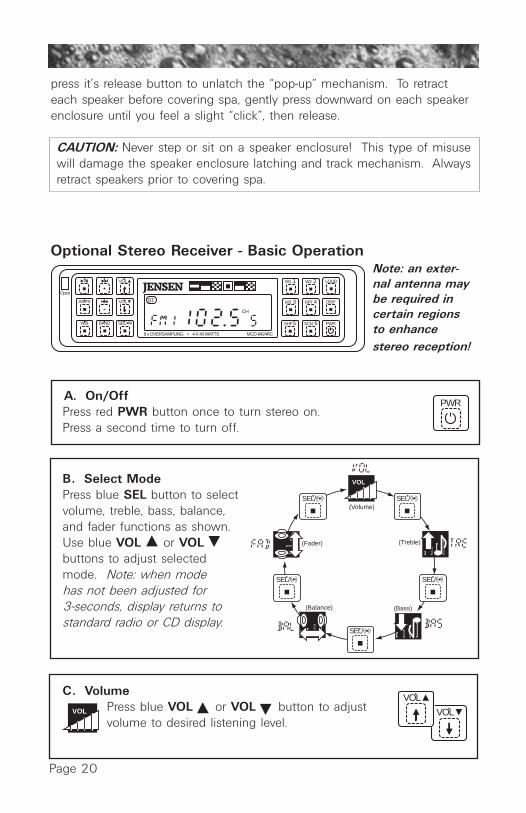
Optional Stereo Receiver - Basic OperationNote: an exter-nal antenna maybe required incertain regionsto enhancestereo reception!
A. On/OffPress red PWR button once to turn stereo on. Press a second time to turn off.
B. Select ModePress blue SEL button to select volume, treble, bass, balance, and fader functions as shown. Use blue VOL or VOL buttons to adjust selected mode. Note: when mode has not been adjusted for 3-seconds, display returns to standard radio or CD display.
C. Volume Press blue VOL or VOL button to adjust volume to desired listening level.
Open
VOL
VOLAS/PS
W/B BAND SEL/
W1 1 W2 2 LOUD
W3 3 RPT 4 DISP
SHF 5 SCN 6 PWR
CH
ST
8 x OVERSAMPLING • 4 X 40 WATTS MCD-9424RC
JENSEN
PWR
SEL/ SEL/
SEL/
SEL/SEL/
VOL
(Volume)
(Treble)
(Bass)(Balance)
(Fader)
VOL
VOLVOL

D. Adjust TreblePress blue SEL button two times toselect treble mode. Then press blueVOL or VOL button to adjust treblerange from -7 to +7.
E. Adjust BassPress blue SEL button three times to select bass mode. Then pressblue VOL or VOL button to adjust bass range from -7 to +7.
F. Adjust BalancePress blue SEL button four times toselect balance mode. Then pressblue VOL or VOL button toadjust speaker balance as desired.
G. Adjust FaderPress blue SEL button five timesto select balance mode. Thenpress blue VOL or VOL button to adjust speaker balance as desired. Note: F15 = FrontSpeakers Only; R15 = RearSpeakers Only.
Page 21
SEL/
VOLVOL
VOLVOL
SEL/
SEL/SEL/SEL/
SEL/SEL/SEL/SEL/
VOL
VOL
SEL/SEL/SEL/SEL/
VOL
VOL
SEL/

Page 22
H. Bass BoostPress grey LOUD button to increase the bass output. LOUD appears on the display.
I. Set ClockPress and hold grey DISP button for 3-seconds until time display flashes. Within 3 seconds, press blue + or - button to set displayed hours and minutes. Unit stores clock settings andreturns to normal operation 3-seconds after lastkey press.
Optional Stereo Receiver - Weather Band and Radio Operation
A. Select a Weather BandThe stereo receiver has a three channelNOAA Weather Radio receiver. NOAAWeather Radio broadcasts NationalWeather Service warnings, watches, fore-casts, and other hazard information 24-hours a day.
Press the grey WB button to change radio toweather radio receiver. Then press greenW1, W2, or W3 to change between threeweather channels in your area.
LOUD
DISP
W1 1
W2 2
W3 3
W/B

Page 23
B. Select a Radio Station
1. Slow Scan:Press blue + button or - button for less than one second to advance radio frequency up or down one step.
2. Quick Scan: Press blue +button or - button for more than one second to quickly scan radio frequencies. Frequencies continue to change until button is released.
C. Program a Station PresetSix numbered green PRESET buttons (1-6) store and recall stations for each radio band.
Save a Station Preset:1. Press grey BAND button to select desired
radio band, if necessary.
2. Select radio station by pressing blue + button or - button.
3. Press green PRESET button for 3-seconds until receiver beeps, then release. Radio station is now stored in memory.
BAND
W1 1 W2 2
W3 3 RPT 4
SHF 5 SCN 6
BAND
CH
ST
Radio Band
StationPreset Number
W3 3

Page 24
D. Recall a Station Preset1. Press grey BAND button to select
desired radio band, if necessary.2. Press green PRESET button to
recall station preset.
E. Automatically Store StationsFunction selects 6 strongest stations and stores them in current band.1. Press grey BAND button to select desired radio
band, if necessary.2. Press grey AS/PS button for more than
3-seconds (receiver beeps and flashes AST on display). The new stations replace station presets previously stored in that band.
F. Prescan StationsScans stations stored in current band.1. Press grey BAND button to select desired
radio band, if necessary.2. Press grey AS/PS button for less than
3-seconds. The radio pauses for 5-seconds at each station. Press grey AS/PS button again to stop scanning when desired station is reached.
CH
ST
W3 3
BAND
AS/PS
BAND
BAND
AS/PS
Page 25
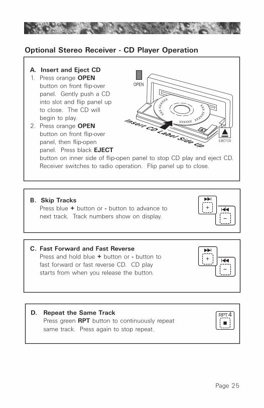
Optional Stereo Receiver - CD Player Operation
A. Insert and Eject CD1. Press orange OPEN
button on front flip-over panel. Gently push a CD into slot and flip panel up to close. The CD will begin to play.
2. Press orange OPENbutton on front flip-over panel, then flip-open panel. Press black EJECTbutton on inner side of flip-open panel to stop CD play and eject CD. Receiver switches to radio operation. Flip panel up to close.
B. Skip TracksPress blue + button or - button to advance to next track. Track numbers show on display.
C. Fast Forward and Fast ReversePress and hold blue + button or - button to fast forward or fast reverse CD. CD play starts from when you release the button.
D. Repeat the Same TrackPress green RPT button to continuously repeat same track. Press again to stop repeat.
Insert CD Label Side Up
XXXX
XXX
XX
XXXX
XXXXXXXXXXX
OPEN
EJECT CD
RPT 4

Page 26
E. Shuffle Play All TracksPress green SHF button to play all tracks on CD in random order one time. Press again to stop shuffle play.
F. Scan (Preview) All TracksPress green SCN button to play first ten seconds of each track on current CD. SCAN appears on display. Press green SCN button again to stop SCAN and listen to track.
G. Pause CD PlayPress grey PLAY/PAUSE button to pause CD play. PAUS appears on display. Press grey PLAY/PAUSEbutton again to resume play.
WARNING!A. Avoid splashing water directly on unit. Unit is
not waterproof!B. Never insert CD into player while wet!C. Inserting wet CD into player will damage unit!D. Never operate unit without rubberized face
shield installed! Shield protects electronics from moisture damage! Operating unit withoutrubberized face shield may void factory warranty!
SHF 5
SCN 6
Page 27
Stereo Receiver Specifications
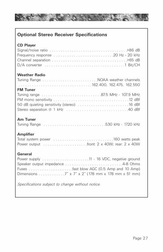
Optional Stereo Receiver Specifications
CD PlayerSignal/noise ratio . . . . . . . . . . . . . . . . . . . . . . . . . . . . . . . . . . .>86 dBFrequency response . . . . . . . . . . . . . . . . . . . . . . . . . . .20 Hz - 20 kHzChannel separation . . . . . . . . . . . . . . . . . . . . . . . . . . . . . . . . . .>65 dBD/A converter . . . . . . . . . . . . . . . . . . . . . . . . . . . . . . . . . . . .1 Bit/CH
Weather RadioTuning Range . . . . . . . . . . . . . . . . . . . . . . . . .NOAA weather channels . . . . . . . . . . . . . . . . . . . . . . . . . . . . . . . . .162.400, 162.475, 162.550FM TunerTuning range . . . . . . . . . . . . . . . . . . . . . . . . . . .87.5 MHz - 107.9 MHzFM mono sensitivity . . . . . . . . . . . . . . . . . . . . . . . . . . . . . . . . . .12 dBf50 dB quieting sensitivity (stereo) . . . . . . . . . . . . . . . . . . . . . . .16 dBfStereo separation @ 1 kHz . . . . . . . . . . . . . . . . . . . . . . . . . . . .40 dBf
Am TunerTuning Range . . . . . . . . . . . . . . . . . . . . . . . . . . . .530 kHz - 1720 kHz
AmplifierTotal system power . . . . . . . . . . . . . . . . . . . . . . . . . . .160 watts peakPower output . . . . . . . . . . . . . . . . . . . .front: 2 x 40W; rear: 2 x 40W
GeneralPower supply . . . . . . . . . . . . . . . . . . . . .11 - 16 VDC, negative groundSpeaker output impedance . . . . . . . . . . . . . . . . . . . . . . . . . .4-8 OhmsFuses . . . . . . . . . . . . . . . . . . . .fast blow AGC (0.5 Amp and 10 Amp)Dimensions . . . . . . . . . . . .7” x 7” x 2” (178 mm x 178 mm x 51 mm)
Specifications subject to change without notice.

Page 28
10.0 Automatic Filtration CyclesYour new spa includes a programmable 24-hour circulation pump whichfilters the water continuously while using less energy than a common 100watt light bulb! The circulation pump draws water through one of two filtercartridges to effectively remove small debris in your spa. Note: the 24-hourcirculation pump system also supplies heated water to the spa when theheater turns on. See page 31 for programming details.
The control system activates a programmable “standard” or “economy” skimming/heating cycles to remove larger debris missed by the 24-hour circulation pump filtration system. These cycles utilize pump#1 and theskimmer bag and second filter cartridge to quickly clear “skim” the water oflarge debris and minimize their “bath-tub ring” effect. Apart from their skimming benefit, each mode also effects the operation of your spa’sheater. Refer to sections 10.1 and 10.2 below for additional information.
10.1 Standard Skimming/Heating ModeStandard skimming/heating mode is typically selected by customers in coldclimates where heatup times are extended due to lower ambient tempera-tures. In this mode, the water temperature is regulated by the set tempera-ture, 24-hour circulation pump, and heater which turns on as needed. Afterthe programmed set temperature is reached, the heater turns off and thecirculation pump continues to operate 24-hours to filter and clean your spa(unless programmed otherwise).
10.2 Economy Skimming/Heating ModeEconomy skimming/heating mode is typically selected by customers inwarm climates where heatup times are minimized due to higher ambienttemperatures. In this mode, the water temperature is regulated by the set temperature, 24-hour circulation pump, and heater only while a pro-grammed skimming/heating cycle is running (unless in summer logic; seenote below). Note: this mode consumes less energy than the standardmode outlined above.
10.3 Selecting Standard or Economy Skimming/Heating ModePress the MODE button to select either “Standard” or “Economy” skim-ming/heating mode. The control panel’s indicator on the right side of theLCD changes to indicate which mode is selected. When an automaticskimming/heating cycle activates, the LCD screen displays the followingmessage:
FILTERCYCLE ON

Page 29
Summer Logic: In warm weather, the water temperature in the hot tub mayexceed the set temperature. This condition may occur due to heat transfer-ence from the main pump and 24-hour circulation pump. If the water tem-perature is higher than 95°F (35°C) and rises two degrees above the set tem-perature, a “Summer Logic” condition occurs that deactivates the circulationpump and ozonator (if equipped). This safety feature cannot be altered!The circulation pump and ozonator will remain off until the water tempera-ture cools to the set temperature (except between12AM-2AM when the cir-culation pumps runs for it’s mandatory 2-hour “clean-up” cycle). To help pre-vent a “Summer Logic” condition, it may be necessary to reduce skim-ming/heating cycle and/or circulation pump run times in warm weather.
10.4 Preset Skimming/Heating CyclesYour hot tub comes with four 30-minute skimming/heating cycles alreadyprogrammed in, beginning at 6:00 a.m., noon, 6:00 p.m., and midnight.You can easily change the start time, or the cycle length for any of thesecycles to suit your individual needs by following the steps in section 11.2,page 30.
10.5 Clean-Up CycleThe clean-up cycle is once per day in both Standard and Economy mode at12:00 PM for two minutes. This is not user programmable. Pump #2 (andJ-380 pump #3) and blower activate for one minute to circulate any waterin the plumbing. After 1 minute they go off, then Pump #1 turns on andruns for 1 minute. If the skimming/heating cycle is also set at 12:00 PM,pump #1 will continue to run for the duration of the cycle.
Page 30
11.0 Programming Instructions
11.1 Adjusting Time of DayThe control system remembers the time of day even in the event of a prolonged power outage. However, it may occasionally be necessary to resetthe time of day. For example: if you are not in the Pacific Time Zone you willwant to reset the time for your own time zone. (The system will automatical-ly adjust to and from daylight savings time.) To accomplish this, press DIS-PLAY, MODE and DISPLAY within five seconds each. A number represent-ing the hour will be displayed, followed by AM or PM. The hour will advanceor decrease each time WARMER ( + ) or COOLER ( - ) is pressed within fiveseconds. Then, press DISPLAY again to display the minutes. Adjust the min-utes as necessary by pressing WARMER ( + ) or COOLER ( - ) After 5 sec-onds, the display will return to normal.
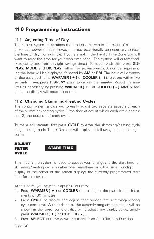
11.2 Changing Skimming/Heating CyclesThe control system allows you to easily adjust two separate aspects of eachof the skimming/heatng cycle: 1) the time of day at which each cycle begins;and 2) the duration of each cycle.
To make adjustments, first press CYCLE to enter the skimming/heating cycleprogramming mode. The LCD screen will display the following in the upper rightcorner:
ADJUST START TIMEFILTERCYCLE
This means the system is ready to accept your changes to the start time forskimming/heating cycle number one. Simultaneously, the large four-digit display in the center of the screen displays the currently programmed starttime for that cycle.
At this point, you have four options. You may:1. Press WARMER ( + ) or COOLER ( - ) to adjust the start time in incre-
ments of 30 minutes.2. Press CYCLE to display and adjust each subsequent skimming/heating
cycle start time. With each press, the currently programmed status will beshown in the large four digit display. To adjust any display value, simplypress WARMER ( + ) or COOLER ( - ).
3. Press SELECT to move down the menu from Start Time to Duration.
START TIME

Page 31
With each press, the currently programmed duration will be shown in thelarge four-digit display. Press WARMER ( + ) or COOLER ( - ) to adjustduration in increments of 15 minutes.
4. Press DISPLAY to make the skimming/heating cycle programming char-acters disappear from the screen and the main display return to showingthe water temperature. If no sensor is pressed within 30 seconds, thescreen automatically returns to the standard water temperature display.
At any time, you may check the programming of any aspect of any skim-ming/heating cycle by first pressing CYCLE then moving through the menuby pressing either CYCLE or SELECT. The programming is changed only bypressing WARMER ( + ) or COOLER ( - ) during this process.
11.3 Programming The Change Filter ReminderYour new spa is equipped with a programmable “ChangeFilter” reminder that appears on the control panel displayafter a specified number of days. It is designed to remindyou to clean and/or replace your filter cartridge(s) on a regular basis butdoes not affect spa operation in any way. This reminder must be reset ateach filter cleaning interval. It offers a selectable range from 10-120 daysor can be disabled. We recommend an initial setting of 30 days, afterwhich you can easily determine whether you need to shorten or lengthenits interval by visually inspecting your filter cartridge. Refer to section 12.1(page 33) for filter cleaning recommendations.
Programming Instructions(1) Press the CYCLE sensor six times. The main display reads “FIL”
indicating the “Change Filter” display program has been accessed.(2) Press SELECT sensor once to display currently programmed duration or
days elapsed since last filter cleaning interval.(3) Press UP or DOWN sensor to change duration as follows:
0 - 10 - 20 - 30 - 40 - 50 - 60 - 70 - 80 - 90 - 100 - 110 - 120 - OFF(4) Press DISPLAY sensor once to save changes and return to the
standard water temperature display. Note: If no sensor is pressed within 30 seconds, the screen will automatically return to the standard water temperature display.
11.4 Programming Circulation Pump Run TimeThe control system allows you to easily adjust two separate aspects of circulation pump operation:1. The time of day (start time) the circulation pump begins operating.2. The length of time (duration) the circulation pump operates.
CHANGEFILTER

Page 32
The factory default start time is 12:00AM (Midnight). The default durationis 24 hours. To make adjustments, press the sensor labeled CYCLE fivetimes to enter the circulation pump programming mode. The LCD screenwill display ADJUST Circ. At this time the system is ready to accept yourchanges.
• Press the SELECT sensor once. The previously programmed start time appears on the LCD display.
• Press WARMER ( + ) or COOLER ( - ) sensors to adjust the start time in 30-minute increments.
• Press the SELECT sensor to program duration.• Press WARMER ( + ) or COOLER ( - ) sensors to program the duration
time in 2 hour increments.• Press DISPLAY to make the circulation pump programming characters
disappear from the screen and the main display return to showing the water temperature. If no sensor is pressed within 30 seconds, the screen will automatically return to the normal water temperature display
Note: In standard skimming/heating mode only, the circulation pump auto-matically activates if the spa requires heat regardless of the programmedstart time and duration.
11.5 Locking Skimming/Heating CyclesYou may keep the skimming/heating cycle programs from beinginadvertently altered by electronically “locking” them. To accomplishthis, simply press CYCLE then, within 30 seconds, press DISPLAY,MODE and WARMER ( + ), within five seconds each.
A padlock symbol will appear on the screen. In this state, the status of the cycle programming may be checked, but may not be altered. To unlock the skimming/heating cycle programming to make changes, simply press DISPLAY, MODE and COOLER ( - ) within five seconds each.
11.6 Panel LockTo help prevent unauthorized use of your spa, the controls incorporate aunique panel locking system which disables the controls on the panel.
To Lock The Panel: Press the DISPLAY, MODE, and WARMER ( + ) sensor pads, in order, within five seconds. A padlock symbolwill appear on the LCD screen. With the panel locked, none of thecomponents can be turned on and the only settings that can beadjusted are the standard/economy operating mode and changing the time
LOCKED
LOCKED

Page 33
of day. All automatic spa functions will operate normally.
To Unlock The Panel: Press DISPLAY, MODE, and COOLER ( - ), in order,within five seconds. The “lock” symbol will disappear. All sensor pads are nowactive.
11.7 Temperature Setting LockTo electronically lock the temperature setting, first enter the “temperature set-ting” mode by pressing WARMER ( + ) or COOLER ( - ). Then, within fiveseconds, press the three sensors described under “Panel Lock” above. Thiswill prevent the temperature setting from being changed by unauthorized per-sons but all other sensors will remain active.
To unlock the temperature setting so that it can be adjusted, simply follow theinstructions above under “To Unlock The Panel.
12.0 Spa MaintenanceProper and regular maintenance of your spa will help it retain its beauty andperformance. Your authorized Jacuzzi Premium dealer can supply you withall the information, supplies, and accessory products you will need toaccomplish this.
12.1 Cleaning The FiltersYour Jacuzzi Premium spa is equipped with a skimmer bag and two high-performance filter cartridges located inside the filter skimmer. Fine debris isfiltered by the circulation pump drawing water through the skimmer bag andcirculation pump cartridge. Larger debris is filtered by the 2-speed pump #1drawing water through the skimmer bag and main pump filter cartridge during normal operation and at each skimming/heating cycle. The skimmerbag and filter cartridges provide unsurpassed water quality by trapping sur-face and suspended particles.
All models also include filters on their footwell suction covers (Page 14)that prevent debris from entering pump 2 (and J-380 pump 3), whenoperating. These filters must remain in place to protect the pump 2(and J-380 pump 3) plumbing network(s). They should be cleaned every 2months, or when weak pump performance is observed.

Page 34
To ensure optimum performance, clean and reuse the skimmer bag and bothcartridges once a month, or as needed. ALWAYS TURN POWER TO SPAOFF BEFORE CLEANING THE FILTER CARTRIDGES! Refer to the filtercleaning/replacement procedure below:
TrappedAir
Bubbles
Submerge both filter cartridges in spa. Tilt threaded end upward to remove trapped air bubbles fromeach cartridge, then keep bothcartridges submerged for step H.
Cartri
dge
1
Cartri
dge
2

Page 35
*Note: to maximize filter life, switch filter cartridge positions at each cleaning.
Periodically, both filter cartridges will need a more thorough cleaning to removeimbedded oils and minerals. For this, we suggest cleaning as illustrated above(Step F), followed by soaking the filter overnight in a plastic container filled witha solution of water and a specially formulated filter cleanser available from yourJacuzzi Premium dealer. We also recommend switching your two filter car-tridges during each cleaning to maximize life. The average life expectancy ofeach filter cartridges is approximately two years with proper care, rotation, andwater quality maintenance. Replacement cartridgesmay be purchased from your Jacuzzi Premium dealer.
12.2 Draining and RefillingAbout every 3 to 6 months, you will want to replace the spa’s water. The fre-quency depends on a number of variables including the amount of use, num-ber of users, attention paid to water quality maintenance, etc. You will know itis time for a change when you cannot control sudsing and/or you can nolonger get the normal feel or sparkle to the water even though the key waterbalance measurements are all within the proper parameters.
WARNING! READ THIS BEFORE DRAINING: To prevent damageto the spa’s components, turn off power to the spa at the cir-cuit breaker before draining it. Do not turn the power back onuntil your spa has been refilled.
H I J

Page 36
CAUTION: There are certain precautions to keep in mind whendraining your spa. If it is extremely cold, and the spa is outdoors,freezing could occur in the lines or the equipment (see “WINTERIZ-ING”, page 38). On the other hand, if it is hot outdoors, do not leavethe spa’s surface exposed to direct sunlight.
To drain your spa, perform the following steps:1. Turn off power to spa at breaker. 2. Locate drain valve on front/lower plastic pan.
Hold larger (rear) body to prevent it from turning, then loosen and remove the front cap to expose underlying male hose threads.
3. Attach garden hose to exposed threads.4. Gently rotate larger (rear) valve body 1/3 turn
counterclockwise to unlock drain valve.5. Pull larger (rear) body outward to open drain.6. After spa drains, perform steps 2-5 in reverse
order to close drain prior to refilling spa.
After refilling, turn on power to the spa andfollow the steps listed under “Start-UpInstructions.” Always fill your spa throughboth filter wall fittings (page 11).
12.3 Cleaning The Spa InteriorTo preserve the sheen of your spa's surface, it is crucial that you avoid using abrasive cleaners or cleaners which have adverse chemical effect on thesurface. If you are not certain as to the suitability of a particular cleanser, con-sult your authorized Jacuzzi Premium dealer. Regardless of the cleanser used,use extreme care to assure that no soap residue is left on the surface. This couldcause severe sudsing when the spa is refilled.
12.4 Pillow CareRemove and clean the headrest pillows as needed with soapy water using a cloth orsoft-bristle brush. To maintain water resistance and luster, apply a quality vinyl condi-tioner once a month. Always remove the pillows when adding chemical shock treat-ment to the spa water. The pillows can be returned to the spa when the sanitizer read-ing drops below 5 ppm.
CAUTION: Never attempt to remove the pillows by pulling on them! Thepillows utilize a bolt-on design that prohibits removal without tools.
Open Drain
2.
3.
4.
5.
UnlockDrain
1. Turn off power to spa.

Page 37
To remove pillows:1. Grasp center pillow insert (A) with
finger tips and gently pry outward from pillow base (C).
2. Use a standard screwdriver to loosen and remove mounting bolts (B) from pillow base.
3. Assemble in reverse order after cleaning. DO NOT overtighten pillow mounting bolts!
12.5 Maintaining the CoverUsing the Jacuzzi Premium insulating spa cover anytime the spa is not in use willsignificantly reduce your operating costs, heat-up time and maintenance require-ments. To prolong the life of the cover, handle it with care and clean it regularlyusing mild soap and water. Periodic treatments with a special conditioner devel-oped for Jacuzzi Premium spa covers will help protect against deterioration causedby UV rays from the sun. Never allow anyone to stand or sit on the cover, and avoiddragging it across rough surfaces.
12.6 Maintaining The Wood CabinetWith time and exposure to the elements, the wood on your spa will tend to lose itsnew appearance. Protecting or reviving the wood surfaces is a fairly simple process.Light sanding with fine-grit sandpaper will help smooth any roughness and regularapplications of a penetrating wood preservative will enhance and protect the rich-ness of the wood. A specially formulated wood stain available from your JacuzziPremium dealer is ideal for this.
NOTE: Do not apply varnish, shellac or other surface sealants to thewood. These tend to react with the chemicals in the wood and the UVrays of the sun, causing yellowing, flaking and peeling.
12.7 Maintaining The Optional Synthetic CabinetYour new spa’s synthetic wood cabinet requires little or no maintenance ofany kind. To clean, simply wipe cabinet with a clean towel and mild soapsolution.
CAUTION: Never spray cabinet with a garden hose for any reasonsince this action may induce an electrical short in the spa’s electrical equipment.

Page 38
12.8 WinterizingYour Jacuzzi Premium spa is designed to automatically protect itself againstfreezing when operating properly. During periods of severe freezing tempera-tures, you should check periodically to be certain that the electrical supply tothe spa has not been interrupted. In extreme, bitter cold weather less than -20 °F (-29 °C), reset the filter cycles for 24-hour operation to protect the spa(i.e. four 6-hour cycles). If you do not intend to use your spa, or if there is aprolonged power outage during periods of severe freezing temperatures, it isimportant that all water be removed from the spa and equipment to protectagainst damage from freezing.
For expert winterization of your spa, contact your authorized JacuzziPremium dealer. In emergency situations, damage can be minimized by tak-ing the following steps:1. Follow the directions on page 35 for draining the spa.2. As the water level drops below the seats, use whatever means
necessary to get the water out of the recessed seating areas and into the footwell.
3. When the water level ceases to drop, use whatever means available toremove any remaining water from the footwell.
4. Turn off power to the spa.5. Remove the equipment-side cabinet panels and locate the drain plugs
in the front of the pump(s) (Figure-A, Page 10). Remove these plugs toallow the water to drain out of the pumps and heater. Note:Approximately one to two gallons will be released during this procedure. Use a wet/dry vacuum or other means to keep this from flooding the equipment compartment. Replace the drain plugs.
6. Loosen the hose clamp on the circulation pump intake behind the con-trol box (Figure-A, Page 10) and pull the hose off (twist hose back andforth while pulling outward). Tip hose down and allow to drain, thenreinstall hose and clamp.
7. Re-install cabinet side panels and cover spa so that no casual moisturecan enter into it.
Consult your Authorized Jacuzzi Premium dealer if you have any questionsregarding winter use or winterizing.
12.9 Restarting Your Spa in Cold WeatherIf you want to start up your spa after it has sat empty for a time in freezingtemperatures, be aware that the water remaining in certain sections of thepiping may still be frozen. This situation will block water flow preventing the

Page 39
spa from operating properly and possibly damaging the equipment. We rec-ommend you consult your dealer for guidance before attempting to re-startyour spa under these conditions.
13.0 Water Quality MaintenanceMaintaining the quality of the water within specified limits will serve toenhance your enjoyment and prolong the life of the spa's equipment. It is afairly simple task, but it requires regular attention because the water chem-istry involved is a balance of several factors. There is no simple formula, andthere is no avoiding it. A careless attitude in regard to water maintenance willresult in poor and potentially unhealthful conditions for soaking and evendamage to your spa. For specific guidance on maintaining water quality, con-sult your Authorized Jacuzzi Premium dealer who can recommend appropri-ate chemical products for sanitizing and maintaining your spa.
CAUTION: Never store spa chemicals inside the spa's equipment bay.
13.1 pH ControlpH is a measure of relative acidity or alkalinity of water and is measured on ascale of 0 to 14. The midpoint of 7 is said to be neutral, above which is alka-line and below which is acidic. In spa water, IT IS VERY IMPORTANT TO MAINTAIN A SLIGHTLY ALKALINE CONDITION OF 7.2 to 7.8. Problems become proportionately severe the further outside of this range the water gets. A low pH will be corrosive to metals in the spa equipment. A high pHwill cause minerals to deposit on the interior surface (scaling). In addition, theability of the sanitation agents to keep the spa clean is severely affected asthe pH moves beyond the ideal range. That is why almost all spa water testkits contain a measure for pH as well as sanitizer.
13.2 SanitizingTo destroy bacteria and organic compounds in the spa water, a sanitizermust be used regularly. Chlorine and Bromine are the two most popularsanitizers used to date. Many other additives are available for your spa.Some are necessary to compensate for out-of-balance water, some aid in

cosmetic water treatment and others simply alter the feel or smell of thewater. Your Authorized Jacuzzi Premium dealer can advise you on the useof these additives.
CAUTION: Do not use chlorine tablets (Trichlor) in your spa. This chemicalcan have an extremely corrosive effect on certain materials in the spa.Damage caused by use of this chemical, or improper use of any chemicals,is not covered under the spa's warranty.
13.3 Optional CD Ozone Water Maintenance SystemIf you have elected to have your spa equipped with the optional JacuzziPremium CD Ozone water purification system you will find that your waterstays fresh and clear with significantly less chemical sanitizer usage. You willalso probably be able to go longer between complete spa drainings. TheCD ozone unit operates in conjunction with the circulation pump.
13.4 Summer LogicWhen the actual spa water temperature reaches up to 2 °F(1 °C) above the set temperature, the spa goes into “summer logic.” The circulation pump will turn off automat-ically to avoid adding additional heat to the water, eventual-ly creating an overheat condition. This setting is not user-programmable.
Note: The summer logic does not take effect until the spa water tempera-ture reaches 95 °F (35 °C). This condition is more likely in excessively hotweather. Remember, the spa’s ability to cool is directly affected by theambient temperature. An excessively hot ambient temperature may preventthe spa from cooling down because it’s fully insulated construction isdesigned to retain heat and to minimize operating costs.
Page 40

Page 41
14.0 Troubleshooting - Display MessagesThere are a number of unique functions designed into your Jacuzzi Premiumspa to protect it from damage and/or to aid in troubleshooting. Following isa listing of all the possible messages along with their meanings:
MESSAGE MEANINGOverheat Protection (Heater is deactivated, pump’slow speed is activated). Water temperature isabove acceptable limits. Do not enter the water!When the actual water temperature is approxi-mately 2 °F (1 °C) above the set temperature, the circulation pump will stop operating to reduce (frictional) heating. Remove spa cover to speed cooling (CAUTION! Never leave spa uncovered when children are present!) See “WATER IS TOO HOT” on page 44. If condition persists, contact your authorized Jacuzzi Premium dealer.
If the spa water is more than 20 °F (-7 °C) cooler than the temperature setpoint, the low speed pump #1 and heater will automatically activate to provide freeze protection. The spa will stay in thismode until the water temperature reaches 15 °F (-9 °C) below the set temperature. No correctiveaction is necessary.
FLOW SWITCH (Heater is deactivated. Pump mayalso be deactivated). Proper flow of water is inhibit-ed or a flow switch has malfunctioned. Check forproper water level and for a clogged circulationpump filter cartridge (Sec. 12.1, Page 33-35).Contact your dealer or service center.
*NOTE: THIS MESSAGE CAN ALSO APPEAR IF THE PUMP HAS NOTREGAINED PRIME AFTER THE SPA HAS BEEN DRAINED ANDREFILLED. IF YOU SUSPECT THAT THIS IS THE CASE, SEE THEINSTRUCTIONS ON PAGE 43 UNDER “PUMP DOES NOT OPERATE...”
Panel sensors have been pressed too many times in ashort period of time. Because this could cause exces-sive wear on equipment components, panel sensorsare temporarily deactivated. Panel sensors will
*

Page 42
automatically re-activate if no sensor is pressed for 30seconds.
Circuit board temperature has exceeded acceptablelimit. This message will disappear when the circuitboard temperature drops below acceptable limit. Ifcondition persists, provide shade for equipment sideof spa.
FREEZE PROTECTIONA potential freeze condition has been detected. Noaction is required. Pump(s) operate until the spa is outof danger. Note: This error commonly occurs whenthe spa is first filled because tap water is often verycold.
Communication between the control panel and/orremote control panel and circuit board is faulty.Contact your dealer or service center.
"WATCHDOG" (spa is deactivated)A problem has been detected which could causedamage to the spa or its components. Contact yourdealer or service center.
OPEN SENSOR (heater disabled) ORSHORTED SENSOR (spa is deactivated)The high-limit temperature sensor is non-functional. Thismust be repaired only by a dealer or authorized servicecenter.
OPEN OR SHORTED SENSOR (heater disabled)The main sensor is non-functional. This must berepaired only by a dealer or authorized service center.
CLOSED OR SHORTED FLOW SWITCH ON SYSTEM STARTUP (system disabled) Flow switchis non-functional. This must be repaired only by adealer or qualified service organization.
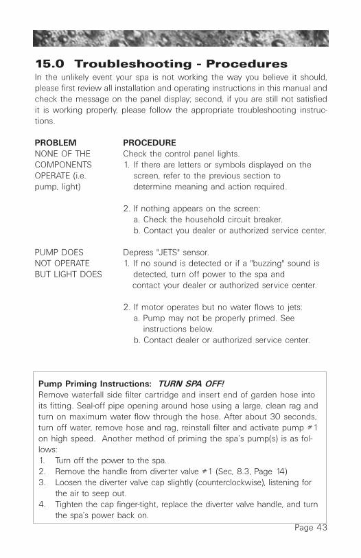
Page 43
15.0 Troubleshooting - ProceduresIn the unlikely event your spa is not working the way you believe it should,please first review all installation and operating instructions in this manual andcheck the message on the panel display; second, if you are still not satisfiedit is working properly, please follow the appropriate troubleshooting instruc-tions.
PROBLEM PROCEDURENONE OF THE Check the control panel lights.COMPONENTS 1. If there are letters or symbols displayed on theOPERATE (i.e. screen, refer to the previous section topump, light) determine meaning and action required.
2. If nothing appears on the screen:a. Check the household circuit breaker.b. Contact you dealer or authorized service center.
PUMP DOES Depress "JETS" sensor.NOT OPERATE 1. If no sound is detected or if a "buzzing" sound isBUT LIGHT DOES detected, turn off power to the spa and
contact your dealer or authorized service center.
2. If motor operates but no water flows to jets:a. Pump may not be properly primed. See
instructions below.b. Contact dealer or authorized service center.
Pump Priming Instructions: TURN SPA OFF!Remove waterfall side filter cartridge and insert end of garden hose intoits fitting. Seal-off pipe opening around hose using a large, clean rag andturn on maximum water flow through the hose. After about 30 seconds,turn off water, remove hose and rag, reinstall filter and activate pump #1on high speed. Another method of priming the spa’s pump(s) is as fol-lows:1. Turn off the power to the spa.2. Remove the handle from diverter valve #1 (Sec, 8.3, Page 14)3. Loosen the diverter valve cap slightly (counterclockwise), listening for
the air to seep out.4. Tighten the cap finger-tight, replace the diverter valve handle, and turn
the spa’s power back on.

Page 44
Note: This method must be used for the single speed pump(s) in all spasbecause pump #2 (and J-380 pump #3) are not connected to the filter.
CAUTION: If freezing conditions exist and pump is not opera-tional, take measures to protect the system from freeze damage.See “Winterizing” (Page 38).
POOR JET ACTION 1. Make certain the pump is on high speed.2. Check position of diverter valve3. Open air control for selected jet system.4. Check for adequate water level.5. Check for dirty filter cartridge.6. Check for dirty filters on both pump #2
footwell suction covers (Page 14).
WATER IS TOO HOT. 1. Reduce thermostat setting.2. Reduce skimming/heating cycle length. Even
with heater off, water temperature can increasefrom prolonged pump operation (Page 30).
NO HEAT 1. Check thermostat setting.2. Keep the cover in place while heating.3. Verify which skimming/heating mode is
selected, standard or economy (Page 28).4. If “heater on” indicator is lit, but no
temperature rise is experienced after a reasonable period of time, contact your dealeror authorized service center.
Should checking the above steps fail to correct the problem, please call yourdealer so that he may arrange service.
Jacuzzi Premium builds the best spas in the industry. Nonetheless, we arealways striving to improve the quality and features of our products. Your inputas a Jacuzzi Premium spa owner is a cherished part of this process. If youhave any comments or suggestions, or if you wish to be informed on any newproducts for your spa, please write to us.
CONGRATULATIONS on your good taste and welcome to the happiest andmost relaxed family in the world!

Page 45
16.0 Wiring DiagramJ-350/J-360/J-370 Models (USA/Canada 60Hz)
Po
wer
Inp
ut:
240
VA
C, 6
0A /
50A
/ 30
A
1 P
HA
SE
, 60H
z; U
SE
MIN
. 6 A
WG
CO
PP
ER
C
ON
DU
CTO
RS
ON
LYRem
ote
Pan
elM
ain
Pan
el
Tran
sfor
mer
T1
Flo
wS
witc
h
HI-
Lim
it F
reez
e S
enso
r
Tem
pera
ture
Sen
sor
Spa
Lig
ht
Opt
ions
Sen
sors
LCD
Pan
elJ8
J4
J3
TB
5
TB
2
TB
1
TB
3
PU
MP
1
PU
MP
2
TB
1
TB
6
TB
4
TB
3
J6J7
K13
K1
K2
K3
K4
K5
K6
J1 J2
K7
K8
HE
AT
ER
5.5
kW1
12
12
2
CD
Ozo
ne(O
ptio
nal)
13
58
10
WH
TW
HT
WH
T
WH
T
LO HI
HI
BLK
BLK
BLK
BLK
RE
D
RE
D
F1
30A
, 250
VS
C-3
0To
Hea
ter
Rel
ays
ST
ER
EO
(Opt
iona
l)
Z1
RE
DG
RN
BL
K
CIR
CU
LAT
ION
PU
MP
Thi
s de
vice
com
plie
s w
ith P
art 1
5 of
the
FC
C r
ules
. O
pera
tion
is s
ubje
ct to
the
follo
win
g tw
o co
nditi
ons:
1.T
his
devi
ce m
ay n
ot c
ause
har
mfu
l in
terf
eren
ce.
2.T
his
devi
ce m
ust a
ccep
t any
in
terf
eren
ce r
ecei
ved
incl
udin
g in
terf
eren
ce th
at m
ay c
ause
un
desi
red
oper
atio
n.
Sel
ect
Cyc
le
Mod
e
Dis
play
y
y
Change
Filter
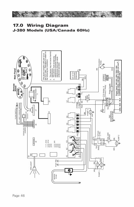
Page 46
17.0 Wiring Diagram J-380 Models (USA/Canada 60Hz)
SE
NS
OR
S
Po
wer
Inp
ut:
240
VA
C, 6
0A /
50A
/ 40
A1
PH
AS
E, 6
0Hz;
US
E M
IN. 6
AW
G (
10 m
m2 )
CO
PP
ER
CO
ND
UC
TOR
S O
NLY
J4
J8
J2
K8
K6
K5
K4
K1
K2
K3
K7
J1
Z1
J6J7
J3
OP
TIO
NS
FLO
W S
WIT
CH
HI -
LIM
IT /
FR
EE
ZE
SE
NS
OR
TR
AN
SF
OR
ME
RT
1
RE
D
Red
Wht
Wht
WhtB
lk
Blk R
ed
Blk
BL
K
Blk
20A
, 250
VM
DA
20F
2
PU
MP
3
PU
MP
1
T92
Rel
ay
HI
Wht
Wht
Blk
Blk
PU
MP
2H
I
HI
LO
TB
3
TB
2T
B6
TB
1
TB
1
GR
N
13
56
810
12
12
JP20
JP19
JP9
1 1 3 5 7 9 1 3 5 7 9 11 13
TE
MP
ER
AT
UR
ES
EN
SO
R
To H
eate
r &
P
ump
2 R
elay
Fro
m
TB
1
SP
A L
IGH
TT
B5
Fro
m T
B1
30A
, 25
0VS
C-3
0F
1
UV
or
CD
Ozo
nato
r(O
ptio
nal)
INT
ER
LOC
KJU
MP
ER
Circ
ulat
ion
Pum
p
ST
ER
EO
(Opt
iona
l)
Thi
s de
vice
com
plie
s w
ith p
art 1
5 of
th
e F
CC
rul
es.
Ope
ratio
n is
sub
ject
to
the
follo
win
g tw
o co
nditi
ons:
1.T
his
devi
ce m
ay n
ot c
ause
har
mfu
l in
terf
eren
ce.
2.T
his
devi
ce m
ust a
ccep
t any
in
terf
eren
ce r
ecei
ved
incl
udin
g in
terf
eren
ce th
at m
ay c
ause
un
desi
red
oper
atio
n.
Pow
er S
uppl
y
Rem
ote
Pan
elM
ain
Pan
el
HE
AT
ER
5.5
kW
Sel
ect
Cyc
le
Mod
e
Dis
play
y
y
Change
Filter

Page 47
Po
wer
Inp
ut:
230
-240
VA
C, 4
0A /
30A
/ 20
A
1-P
has
e, 5
0Hz;
US
E M
IN. 6
AW
G (
10 m
m2 )
CO
PP
ER
CO
ND
UC
TOR
S O
NLY
J8
J3
TB
7
TB
1
TB
1
TB
6
TB
5
TR
4T
R2
J6J7
OP
TIO
NS
SE
NS
OR
SLC
D P
AN
EL
Spa
Lig
ht
HE
AT
ER
2.7
kW
NN
LL
1 2
3
1 2
1 2
Fro
m
TB
1
NN
N
N
L
L
NL
L
PU
MP
2
To H
eate
rR
elay
s
HI
HI
LO
BLU
BR
N
BLK
GR
N
Circ
ulat
ion
Pum
p
F1
20A
, 250
VS
C-2
0
Thi
s eq
uipm
ent w
as te
sted
and
foun
d to
be
fully
com
plia
nt w
ith E
N55
014-
1 (1
997)
, EN
5501
4-2
(199
7), E
N61
000-
3-2
(199
5), E
N61
000-
3-3
(199
5),
EN
5502
2 C
lass
B, a
nd E
N50
082-
1 (1
992)
S
tand
ards
.S
TE
RE
O(O
ptio
nal)
CD
Ozo
ne(O
ptio
nal)
2 1 2 1
Rem
ote
Pan
elM
ain
Pan
elF
low
Sw
itch
HI-
Lim
it F
reez
e S
enso
r
Tem
pera
ture
Sen
sor
Sel
ect
Cyc
le
Mod
e
Dis
play
y
y
Change
Filter
18.0 Wiring DiagramJ-350/J-360/J-370 Models (Export 50Hz)

Page 48
19.0 Wiring Diagram J-380 Models (Export 50Hz)
Po
wer
Inp
ut:
230
-240
VA
C, 4
0A /
35A
1-
Ph
ase,
50H
z; U
SE
MIN
. 6 A
WG
(10
mm
2 )
CO
PP
ER
CO
ND
UC
TOR
S O
NLY
SE
NS
OR
S
J8J6
J7
J3
OP
TIO
NS
FLO
W S
WIT
CH
HI -
LIM
IT /
FR
EE
ZE
SE
NS
OR
TR
AN
SF
OR
ME
RT
1
TB
3
TB
3T
B4
G
11
11
2
TB
2 21
1 2
PU
MP
1
PU
MP
2P
UM
P 3
HI
HI
LO
TE
MP
ER
AT
UR
ES
EN
SO
R
To H
eate
rR
elay
SP
A
LIG
HT
TB
7
Fro
m T
B1
TB
1
UV
or
CD
Ozo
nato
r(O
ptio
nal)
HE
AT
ER
2.
7kW
, 230
VA
C
Circ
ulat
ion
Pum
p
TB
5
TB
1
2 1
12
3
HI
30A
, 25
0VS
C-3
0
F1
N
NN
NN
N
LN
NN
LL
LL
L
L L
L
L
LN
Red
Bla
ck
J4
ST
ER
EO
(Opt
iona
l)P
ower
Sup
plyRem
ote
Pan
el
Sel
ect
Cyc
le
Mod
e
Dis
play
y
y
Mai
n P
anel
Change
Filter
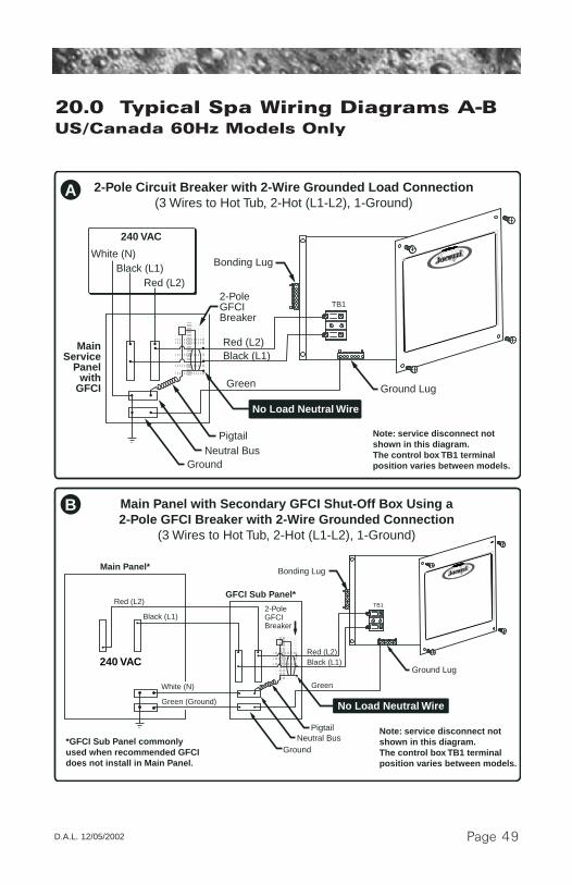
Page 49
TB1
TB1
Red (L2)
PigtailNeutral Bus
Ground
Black (L1)
Green
MainService
Panelwith
GFCI
2-Pole GFCIBreaker
Ground Lug
Bonding Lug
Bonding Lug
2-Pole Circuit Breaker with 2-Wire Grounded Load Connection(3 Wires to Hot Tub, 2-Hot (L1-L2), 1-Ground)
White (N)Black (L1)
Red (L2)
240 VAC
No Load Neutral Wire
Note: service disconnect not shown in this diagram. The control box TB1 terminal position varies between models.
Red (L2)
Red (L2)
PigtailNeutral Bus
Ground
Black (L1)
Black (L1)
Green
GFCI Sub Panel*
Main Panel*
2-Pole GFCIBreaker
Ground Lug
No Load Neutral Wire
Main Panel with Secondary GFCI Shut-Off Box Using a2-Pole GFCI Breaker with 2-Wire Grounded Connection
(3 Wires to Hot Tub, 2-Hot (L1-L2), 1-Ground)
White (N)
Green (Ground)
*GFCI Sub Panel commonly used when recommended GFCI does not install in Main Panel.
Note: service disconnect not shown in this diagram. The control box TB1 terminal position varies between models.
B
A
240 VAC
20.0 Typical Spa Wiring Diagrams A-BUS/Canada 60Hz Models Only
D.A.L. 12/05/2002

.

.

Jacuzzi® Premium14525 Monte Vista Ave. • Chino, CA 91710
Website: http://www.jacuzzipremium.com
6530-224, Rev. D © 2002 Jacuzzi Premium Printed in U.S.A.