20 mhz function generator service manual - user equipuserequip.com/files/specs/1196/tg120 service...
TRANSCRIPT

TG120 20 MHz Function Generator
Service Manual
Book Part Number 48591-0520 Issue 1

Table of Contents Specification 1
Safety 3
Installation 4
General 5
Circuit Descriptions 6
Calibration 7
Parts List 8
Component Layout 12
Circuit Diagram 13
Specification
FREQUENCY Frequency Range: 0·2Hz to 20MHz in 8 overlapping decade ranges with fine adjustment
by a vernier.
Vernier Range: >10:1 on each range.
Vernier Accuracy: Typically ± 5% of full scale.
SWEEP MODE (EXTERNAL) Sweep Range: Typically >20:1.
Input Impedance: 82 kΩ
Input Sensitivity: Typically 0 to 2V for 10:1 sweep.
Maximum Allowable Input Voltage:
± 10V
Maximum Slew Rate of sweep voltage:
0·1V/us
OPERATING MODES (Specifications apply for the top decade of each frequency range and output 10V peak-to-peak into 50Ω termination).
SINE Distortion: Typically 2% on 200, 2k and 20k ranges.
Amplitude Flatness: ± 0·2dB to 200kHz; ± 2dB to 20MHz.
TRIANGLE Linearity: Typically 99% on kHz ranges.
1
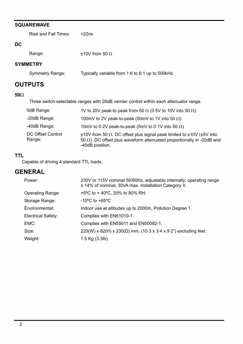
SQUAREWAVE
Rise and Fall Times: <22ns
DC
Range: ±10V from 50 Ω
SYMMETRY
Symmetry Range: Typically variable from 1:6 to 6:1 up to 500kHz.
OUTPUTS 50Ω
Three switch-selectable ranges with 26dB vernier control within each attenuator range.
0dB Range: 1V to 20V peak-to peak from 50 Ω (0·5V to 10V into 50 Ω).
-20dB Range: 100mV to 2V peak-to-peak (50mV to 1V into 50 Ω)
-40dB Range: 10mV to 0·2V peak-to-peak (5mV to 0·1V into 50 Ω)
DC Offset Control Range:
±10V from 50 Ω. DC offset plus signal peak limited to ±10V (±5V into 50 Ω). DC offset plus waveform attenuated proportionally in -20dB and -40dB position.
TTL Capable of driving 4 standard TTL loads.
GENERAL Power: 230V or 115V nominal 50/60Hz, adjustable internally; operating range
± 14% of nominal; 30VA max. Installation Category II.
Operating Range: +5ºC to + 40ºC, 20% to 80% RH.
Storage Range: -10ºC to +65ºC
Environmental: Indoor use at altitudes up to 2000m, Pollution Degree 1.
Electrical Safety: Complies with EN61010-1.
EMC: Complies with EN55011 and EN50082-1.
Size: 220(W) x 82(H) x 230(D) mm, (10·3 x 3·4 x 9·2”) excluding feet.
Weight: 1·5 Kg (3.3lb).
2
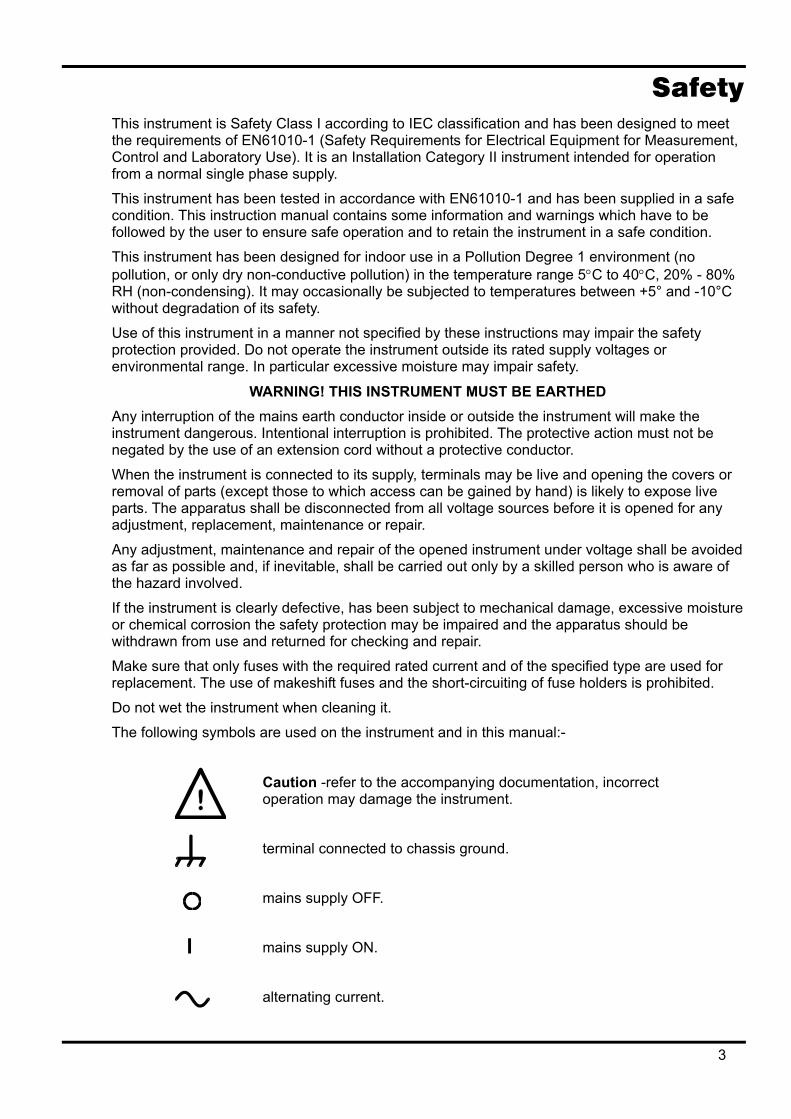
Safety This instrument is Safety Class I according to IEC classification and has been designed to meet the requirements of EN61010-1 (Safety Requirements for Electrical Equipment for Measurement, Control and Laboratory Use). It is an Installation Category II instrument intended for operation from a normal single phase supply.
This instrument has been tested in accordance with EN61010-1 and has been supplied in a safe condition. This instruction manual contains some information and warnings which have to be followed by the user to ensure safe operation and to retain the instrument in a safe condition.
This instrument has been designed for indoor use in a Pollution Degree 1 environment (no pollution, or only dry non-conductive pollution) in the temperature range 5°C to 40°C, 20% - 80% RH (non-condensing). It may occasionally be subjected to temperatures between +5° and -10°C without degradation of its safety.
Use of this instrument in a manner not specified by these instructions may impair the safety protection provided. Do not operate the instrument outside its rated supply voltages or environmental range. In particular excessive moisture may impair safety.
WARNING! THIS INSTRUMENT MUST BE EARTHED Any interruption of the mains earth conductor inside or outside the instrument will make the instrument dangerous. Intentional interruption is prohibited. The protective action must not be negated by the use of an extension cord without a protective conductor.
When the instrument is connected to its supply, terminals may be live and opening the covers or removal of parts (except those to which access can be gained by hand) is likely to expose live parts. The apparatus shall be disconnected from all voltage sources before it is opened for any adjustment, replacement, maintenance or repair.
Any adjustment, maintenance and repair of the opened instrument under voltage shall be avoided as far as possible and, if inevitable, shall be carried out only by a skilled person who is aware of the hazard involved.
If the instrument is clearly defective, has been subject to mechanical damage, excessive moisture or chemical corrosion the safety protection may be impaired and the apparatus should be withdrawn from use and returned for checking and repair.
Make sure that only fuses with the required rated current and of the specified type are used for replacement. The use of makeshift fuses and the short-circuiting of fuse holders is prohibited.
Do not wet the instrument when cleaning it.
The following symbols are used on the instrument and in this manual:-
Caution -refer to the accompanying documentation, incorrect operation may damage the instrument.
terminal connected to chassis ground.
mains supply OFF.
l mains supply ON.
alternating current.
3

Installation MAINS OPERATING VOLTAGE
The operating voltage of the instrument is shown on the rear panel. Should it be necessary to change the operating range from 230V to 115V or vice-versa, change the transformer connections following the appropriate diagram below:
230V Operating - Primaries in series
115V Operation - Primaries in parallel
MAINS LEAD When a three core mains lead with bare ends is provided it should be connected as follows:-
Brown - Mains live Blue - Mains neutral
Green/Yellow - Earth
WARNING! THIS INSTRUMENT MUST BE EARTHED
Any interruption of the mains earth conductor inside or outside the instrument will make the instrument dangerous. Intentional interruption is prohibited.
4

General Service Handling Precautions
Service work or calibration should only be carried out by skilled engineers.
Please note the following points before commencing work.
The tracks on the printed circuit board are very fine and may lift if subjected to excessive heat. Use only a miniature temperature controlled soldering iron and remove all solder (on both sides of the joint) with solder wick or suction before attempting to remove a component.
Care should be taken when handling to avoid damage by static discharge
Dismantling the instrument 1. Invert the instrument and remove the 4 screws securing the case upper. Holding the case
halves together, turn the instrument the correct way up and lift off the case upper ensuring the front and rear panels stay with the case lower.
2. To remove the pcb from the front panel, pull off the control knobs and remove the nuts beneath. Remove the 3 BNC nuts.
3. Reassemble in the reverse order.
Caution EMC To ensure continued compliance with the EMC directive the following precautions should be observed:
a) after dismantling the unit for any reason ensure that any signal and ground connections are remade correctly. Always ensure all screws are correctly refitted and tightened.
b) In the event of part replacement becoming necessary, only use components of an identical type.
5

Circuit Descriptions Power Supply - DC Regulation
The voltage regulators are mounted on a separate pcb. IC10 and IC11 provide ±15V, IC8 and IC9 provide ± 5V.
Waveform Generation IC1 is an integrated waveform generator and provides sinewave, squarewave and triangle output.
Q1 to Q6 select the range capacitor. The 20MHz and 2MHz ranges use the same range capacitor VC1.
The dial and sweep voltages are summed by IC5A; IC5B inverts the output of IC5A. IC4C and IC4B select the full-scale input current to the frequency control pin 10 of IC1 for the different ranges as follows. On 2Hz to 200kHz ranges IC4B and IC4C select VR6 and R45. IC4D connects the FADJ pin to 0V. On 2MHz range IC4B and IC4C select VR9 and FADJ remains at 0V. On 20MHz range IC4B and IC4C select R44 (R52 is in circuit on all ranges). IC4D connects FADJ to 0V via R46; the 250uA current sink inside IC1 causes -3V to be developed across R46 setting IC1 to its frequency double mode.
IC5C buffers the symmetry control. The control voltage to the DADJ pin needs to be inverted when sine or triangle are selected to maintain the same direction of operation of VR2 as in squarewave mode. IC5D provides the inversion.
The waveform address pins A0 and A1 set the output waveform.
The selected waveform is produced at the OUT pin and is 2Vpk-pk.
Waveform Generation - Aux Output IC2 is a zero crossing detector with hysteresis provided by R19 and R59.
Preamplifier R18,R17 and VR7 set the gain of IC3 to approximately 2 to give approximately 4Vpk-pk output. When no waveform is selected (DC), Q7 pulls pin 8 to 0V disabling the amplifier. The amplifier output is then in a high impedance state and IC7 input is grounded via IC3's feedback resistors.
Output Amplifier R26,R27 and R54 set the gain to approximately 5 to give 20Vpk-pk output.
D1,D2 D4 and D5 provide some protection against voltages being applied to the 50 Ω.
IC6A amplifies the voltage set by VR4 the DC Offset control by 2.1 to give at least ±10V DC offset range.
6

Calibration Equipment Required
Oscilloscope
Distortion meter
DMM
Only the case upper needs to be removed to gain access to all adjustments. Holes through the pcb give access to the trimmers.
Allow 30 minute warm-up before commencing.
The 20MHz and 2MHz range calibrations are inter-active and therefore should be adjusted in the order shown.
1. Power Supply Check the power supply voltages at PJ2 on the PSU board
+15V ± 0.5V
-15V ± 0.5V
+5V ± 0.25V
-5V ± 0.25V
2. DC Offset Set Function switch to DC, set DC Offset control to centre detent, attenuators to 0dB.
Adjust VR8 for 0V ± 10mV at Main Output
3. Frequency Select sinewave, connect a frequency counter to either output
Set dial to 2.0
20MHz range adjust VC1 for 19.8 to 20.2MHz
2MHz range adjust VR9 for 1.98 to 2.02MHz
20kHz range adjust VR6 for 19.8 to 20.2kHz
4. Amplitude Select squarewave, dial at 2.0, 2k range, Amplitude control to maximum. Adjust VR7 for 10.2Vpk-pk into 50 Ω.
5. Distortion Set dial to 2.0, 2k range, sinewave, Symmetry switch to off. Adjust VR5 for minimum distortion.
7
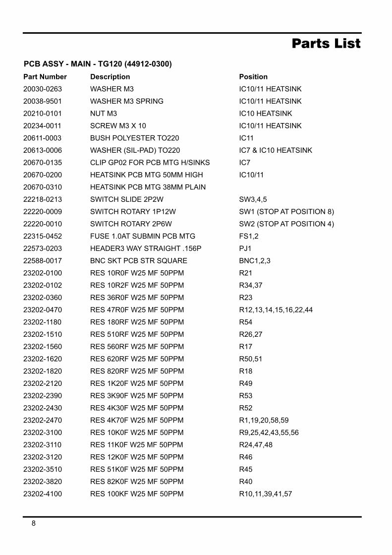
Parts List PCB ASSY - MAIN - TG120 (44912-0300) Part Number Description Position
20030-0263 WASHER M3 IC10/11 HEATSINK
20038-9501 WASHER M3 SPRING IC10/11 HEATSINK
20210-0101 NUT M3 IC10 HEATSINK
20234-0011 SCREW M3 X 10 IC10/11 HEATSINK
20611-0003 BUSH POLYESTER TO220 IC11
20613-0006 WASHER (SIL-PAD) TO220 IC7 & IC10 HEATSINK
20670-0135 CLIP GP02 FOR PCB MTG H/SINKS IC7
20670-0200 HEATSINK PCB MTG 50MM HIGH IC10/11
20670-0310 HEATSINK PCB MTG 38MM PLAIN
22218-0213 SWITCH SLIDE 2P2W SW3,4,5
22220-0009 SWITCH ROTARY 1P12W SW1 (STOP AT POSITION 8)
22220-0010 SWITCH ROTARY 2P6W SW2 (STOP AT POSITION 4)
22315-0452 FUSE 1.0AT SUBMIN PCB MTG FS1,2
22573-0203 HEADER3 WAY STRAIGHT .156P PJ1
22588-0017 BNC SKT PCB STR SQUARE BNC1,2,3
23202-0100 RES 10R0F W25 MF 50PPM R21
23202-0102 RES 10R2F W25 MF 50PPM R34,37
23202-0360 RES 36R0F W25 MF 50PPM R23
23202-0470 RES 47R0F W25 MF 50PPM R12,13,14,15,16,22,44
23202-1180 RES 180RF W25 MF 50PPM R54
23202-1510 RES 510RF W25 MF 50PPM R26,27
23202-1560 RES 560RF W25 MF 50PPM R17
23202-1620 RES 620RF W25 MF 50PPM R50,51
23202-1820 RES 820RF W25 MF 50PPM R18
23202-2120 RES 1K20F W25 MF 50PPM R49
23202-2390 RES 3K90F W25 MF 50PPM R53
23202-2430 RES 4K30F W25 MF 50PPM R52
23202-2470 RES 4K70F W25 MF 50PPM R1,19,20,58,59
23202-3100 RES 10K0F W25 MF 50PPM R9,25,42,43,55,56
23202-3110 RES 11K0F W25 MF 50PPM R24,47,48
23202-3120 RES 12K0F W25 MF 50PPM R46
23202-3510 RES 51K0F W25 MF 50PPM R45
23202-3820 RES 82K0F W25 MF 50PPM R40
23202-4100 RES 100KF W25 MF 50PPM R10,11,39,41,57
8

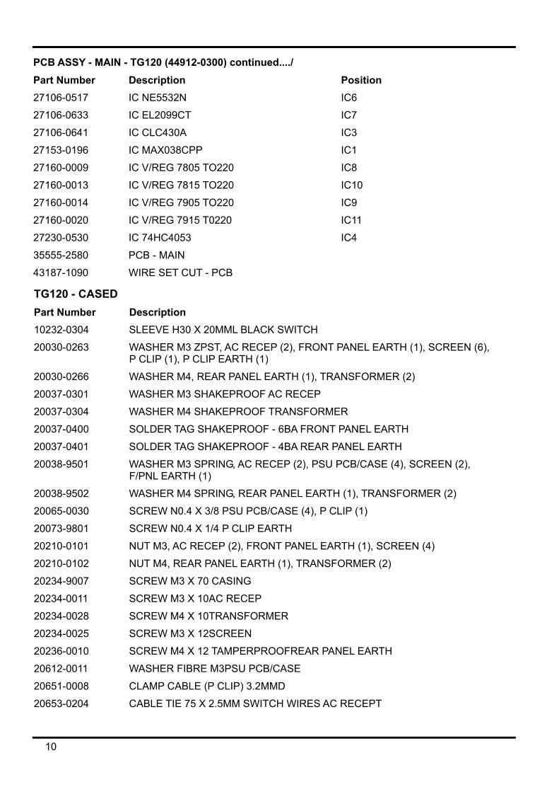
PCB ASSY - MAIN - TG120 (44912-0300) continued...../ Part Number Description Position
23202-5200 RES 2M00F W25 MF 50PPM R38
23206-0412 RES 41R2F W60 MF 50PPM MRS25 R32,33,35,36
23206-1200 RES 200RF W60 MF 50PPM MRS25 R28,29,30,31
23301-0445 RES NETWK SIL 100K X 8 RP1
23347-0260 POT 10K LIN SPLINE+DETENT 25MM VR2,4
23347-0270 POT 1K LIN SPLINE SHAFT 25MM VR3
23347-0280 POT 10K LIN LA20BU VR1
23377-1220 RES PS/H 220R CF 10MM VR7
23377-1470 RES PS/H 470R CF 10MM VR5
23377-2220 RES PS/H2K2 CF 10MM VR9
23377-3100 RES PS/H10K CF 10MM VR8
23377-3220 RES PS/H22K CF 10MM VR6
23424-0443 CAP10NZ 500V CER D10 P5 C23
23427-0268 CAP22PJ 100V CER NPO P2.5 C8
23427-0325 CAP10NZ63V CER HI K P5 C38,39
23428-1100 CAP 100PG 100V CER NPOP2.5 C35,37
23620-0242 CAP 22NJ 100V 5% P/E P5 C5
23427-9205 CAP47PJ 100V CER NPO P2.5 C21,36
23427-9233 CAP 150PJ 100V CER N150 P2.5 C7
23557-0550 CAP 10U 16V ELEC BIPOLAR P2 C22
23557-0647 CAP 10U 35V ELEC RE2 P2 C10,11,17,18,26,27,31,32
23557-0664 CAP 1000U 35V ELEC RE2 P5 C24,25
23557-0710 CAP 2U2 50V ELEC LOW LEAKAGE C2
23557-0720 CAP 22U 16V ELEC LOW LEAKAGE C1
23620-0246 CAP 100NK 63V P/E P5 C4,9,12-16,19,20,28,29,30,33,34
23620-0247 CAP 220NK 63V P/E P5 C3
23620-0252 CAP 2N2K 63V P/E P5 C6
23984-0015 TRIMCAP 2-22P P/P VC1
25021-0901 DIO 1N4148 D1,2
25061-0200 LED - T1 ROUND (3mm) - RED LED1
25130-9201 DIO ZEN 6V2 W5 D3
25131-0224 DIO ZEN 18V 1W3 D4,5
25211-9302 RECTIFIER BRIDGE W02G BR1
25377-5490 TRAN NPN BC549C Q1-8
27103-0040 IC NE529N IC2
27106-0506 IC LM324N IC5
9
PCB ASSY - MAIN - TG120 (44912-0300) continued..../ Part Number Description Position
27106-0517 IC NE5532N IC6
27106-0633 IC EL2099CT IC7
27106-0641 IC CLC430A IC3
27153-0196 IC MAX038CPP IC1
27160-0009 IC V/REG 7805 TO220 IC8
27160-0013 IC V/REG 7815 TO220 IC10
27160-0014 IC V/REG 7905 TO220 IC9
27160-0020 IC V/REG 7915 T0220 IC11
27230-0530 IC 74HC4053 IC4
35555-2580 PCB - MAIN
43187-1090 WIRE SET CUT - PCB
TG120 - CASED Part Number Description 10232-0304 SLEEVE H30 X 20MML BLACK SWITCH
20030-0263 WASHER M3 ZPST, AC RECEP (2), FRONT PANEL EARTH (1), SCREEN (6), P CLIP (1), P CLIP EARTH (1)
20030-0266 WASHER M4, REAR PANEL EARTH (1), TRANSFORMER (2)
20037-0301 WASHER M3 SHAKEPROOF AC RECEP
20037-0304 WASHER M4 SHAKEPROOF TRANSFORMER
20037-0400 SOLDER TAG SHAKEPROOF - 6BA FRONT PANEL EARTH
20037-0401 SOLDER TAG SHAKEPROOF - 4BA REAR PANEL EARTH
20038-9501 WASHER M3 SPRING, AC RECEP (2), PSU PCB/CASE (4), SCREEN (2), F/PNL EARTH (1)
20038-9502 WASHER M4 SPRING, REAR PANEL EARTH (1), TRANSFORMER (2)
20065-0030 SCREW N0.4 X 3/8 PSU PCB/CASE (4), P CLIP (1)
20073-9801 SCREW N0.4 X 1/4 P CLIP EARTH
20210-0101 NUT M3, AC RECEP (2), FRONT PANEL EARTH (1), SCREEN (4)
20210-0102 NUT M4, REAR PANEL EARTH (1), TRANSFORMER (2)
20234-9007 SCREW M3 X 70 CASING
20234-0011 SCREW M3 X 10AC RECEP
20234-0028 SCREW M4 X 10TRANSFORMER
20234-0025 SCREW M3 X 12SCREEN
20236-0010 SCREW M4 X 12 TAMPERPROOFREAR PANEL EARTH
20612-0011 WASHER FIBRE M3PSU PCB/CASE
20651-0008 CLAMP CABLE (P CLIP) 3.2MMD
20653-0204 CABLE TIE 75 X 2.5MM SWITCH WIRES AC RECEPT
10

TG120 - UNCASED (59120-1021) continued..../ Part Number Description 20657-0070 KNOB 21MM DA217 180 GREY 99
20657-0071 CAP C210 FOR 21MM KNOB GREY 99
20657-0080 KNOB 11MM TP111 006 GREY 99
20657-0081 CAP C110 FOR 11MM KNOB GREY 99
20661-0276 SPACER RND 10MMID X 0.8MMT SW1,2
20661-0277 SPACER RND 10MMID X 3.5MMT VR1
22040-0030 FERRITE SLEEVE APPROX 7/14/15L
22115-0330 TRANSFORMER
22219-0050 SWITCH ROCKER DPST SOLDER LUGS
22458-0004 SHROUD INSULATING (MS1 BOOT) AC RECEP
22491-0010 MAINS LEAD 2M RA IEC SKT/STRRPEND
22520-0150 AC MAINS RECEP 10AMP
22575-0203 SKT3W .156 20AWG (Yellow) IDT
31311-9010 ECLIPSE NEOPRENE PAD
33111-9010 ECLIPSE TILT STAND
33331-4650 FRONT PANEL
33331-4660 OVERLAY FRONT PANEL
33331-4670 REAR PANEL
33562-9010 ECLIPSE CASE UPPER
33562-9020 ECLIPSE CASE LOWER
33562-9030 ECLIPSE CASE EXPANDER
33562-9040 ECLIPSE FOOT TYPE A
33562-9050 ECLIPSE FOOT TYPE B
37522-0160 LABEL SER NO - THURLBY-THANDAR
37541-1040 LABEL - CE
43187-1100 WIRE SET CUT CHASSIS
48591-0500 INSTRUCTION BOOK
11

Component Layout
12


Circuit Diagram
13


Thurlby Thandar Instruments Ltd
Glebe Road, Huntingdon, Cambridgeshire PE29 7DR, England Telephone: (44) 01480 412451 Fax: (44) 01480 450409 e mail: [email protected] web site: www.tti-test.com