2 tid stromverteilung 146 237 gb lr (1)
DESCRIPTION
busbar calculationTRANSCRIPT

Technical informationGeneral remarks
146 Rittal Catalogue 33/Power distribution
When developing the Rittal busbar systems and their components, Rittal drew on the latest state of the art and the currently valid stand-ards and regulations. These applications are used by specialist companies worldwide. As well as permanent in-house controls at Rittal, the quality of the SV components is further reinforced by a vast array of tests and approvals.
As product development is an on-going process, we reserve the right to make amendments in line with technical progress.
Application In order to avoid injury and damage to property, busbar systems must only be assembled and used by suitably trained and qualified personnel. The valid technical regulations, standards and provisions must, of course, be observed. Users are required to carefully observe the information and instruc-tions supplied by Rittal, and where necessary to forward them to downstream users and/or customers with a special advice note. In particular, the specified tightening torques of electrical terminal con-nections must be observed in order to achieve an optimum contact pressure. After transportation the connections must be checked and retightened if necessary.
As a general principle, NH fuses are intended for use by electricians or persons who have received training in electrical engineering.
Please observe the following regulations and instructions regarding the connection of NH equipment: ● Observe the specifications to VDE 0105 – 100 ● Before switching on, ensure that the cover is precisely located in
the chassis ● If the cover is not fully open, the fuse inserts may be live, depend-
ing on the direction of infeed ● Connect quickly
Technical data and catalogue information/operating conditionsPower distribution components are used in conjunction with a wide range of different switchgear, assemblies and components for power distribution. These various assemblies and components necessitate a wide range of different operating and ambient conditions which are, firstly, outside of Rittal’s sphere of influence, and secondly, must be guaranteed in order to allow safe operation by the plant manufac-turer.
Unless otherwise indicated, IEC 61 439-1/IEC 61 439-2 and the specified ambient conditions for interior sitings up to contamination level 3 and overvoltage category IV apply as the basis for Rittal power distribution components in the IEC market. At enclosure inter-nal temperatures of > 35°C, application-specific derating should be provided where necessary. Specifically in relation to the limit temperatures specified in IEC/EN 61 439-1 (table 5) the following factors should be given critical consideration by the plant manufacturer:
● Arrangement of components in respect of the thermally interac-tive influences in the overall structure
● Heat loss of the circuit-breakers and fuses used● Active/passive ventilation measures● Required cable cross-sections according to standard and/or
manufacturer data● Operating mode of plant (switching cycles etc.)● Consideration of the operating and ambient conditions● Consideration of the simultaneity factor● Consideration of the rated load factor (RDF) ● Consideration of the load factor
It should also be noted that the horizontal installation position is the standard installation position for busbar systems, and this therefore produces the vertical installation position for top-mounted equip-ment. Once assembly of the system has been completed, the mini-mum creepage distances and clearances to IEC/EN 60 664-1 should be checked.
Chemical contamination caused by direct contact with substances or an excessively chemically charged atmosphere during transporta-tion, storage and operation of the components should be avoided, since this can lead to contact corrosion and other lasting negative influences.
Specifically for the UL market, the requirements to UL 508A apply to plant manufacturers. In particular, depending on the application, the required creepage distances and clearances must be taken into account.

General remarks
Technical information
147Rittal Catalogue 33/Power distribution
● IEC/EN 60 269-1 Low-voltage switchgear Part 1: General requirements
● IEC/EN 61 439-1 Low-voltage switchgear and controlgear assembliesPart 1: General specificationsReplaces IEC/EN 60 439-1
● IEC/EN 61 439-2 Low-voltage switchgear and controlgear assembliesPart 2: Power switchgear and controlgear assembliesReplaces IEC/EN 60 439-1
● IEC/EN 61 439-3 Low-voltage switchgear and controlgear assembliesPart 3: Distribution boards intended to be operated by ordinary persons
● IEC/EN 60 947-1 Low-voltage switchgear controlgear assembliesPart 1: General specifications
● IEC/EN 60 947-3 Low-voltage switchgear and controlgearPart 3: Switches, disconnectors, switch-disconnectors and fuse-combination units
● IEC/EN 60 664-1 Coordination of insulation for electrical operating equipment in low-voltage systems Part 1: Basic principles, requirements and tests
● IEC/EN 60 999-1 Connector parts – Electrical copper conductors – Safety require-ments for screw terminals and screwless terminalsGeneral and specific requirements for terminals for conductors from 0.2 mm2 up to and including 35 mm2
● IEC/EN 60 999-2 Connector parts – Electrical copper conductors – Safety requirements for screw terminals and screwless terminalsPart 2: Special requirements for terminals for conductors greater than 35 mm2 up to and including 300 mm2
● DIN 43 671 Copper busbars, dimensioning for constant current
● DIN 43 673-1 Busbar drill holes and screw fastenings, busbars with rectangular cross-section
● IEC/EN 60 715 Dimensions of low-voltage switchgear – Standardised support rails for the mechanical attachment of electrical components in switching systems
● DIN EN 13 601 Copper and copper alloys – Copper rods and wires for general use in electrical engineering
● UL 248 Low-Voltage Fuses
● UL 4248-1 Fuseholders Part 1: General Requirements
● UL 486 E Equipment Wiring Terminals for use with Aluminium and/or Copper Conductors
● UL 489 Molded-Case Circuit breakers, Molded-Case Switch and Circuit-Breaker Enclosures
● UL 508 Industrial Control Equipment
● UL 508AIndustrial Control Panels
● UL 512 Fuseholders
● UL 845 Motor Control Centers
● UL 891 Switchboards
Glossary of frequently used basic/user regulations for busbar systems and components

Technical informationGeneral remarks
148 Rittal Catalogue 33/Power distribution
Ri4Power low-voltage switchgear assemblies with design certificateThe section types of Ri4Power low-voltage switchgear combinations comply with the design certificate to IEC 61 439-1 and IEC 61 439-2. If planned and executed in accordance with the specifications and assembly instructions for Ri4Power sys-tems, the combination of section types corresponds to a low-voltage switchgear combination with design certificate to IEC 61 439-1 and IEC 61 439-2.
Testing of Ri4Power systems was carried out with the following switchgear brands:● ABB● Eaton● Jean Müller● Mitsubishi● Schneider Electric● Siemens● Terasakiand with RiLine components from Rittal. In contrast to a non-tested switchgear combi-nation, the requirements for the selection of components and switchgear are linked to the tested types. When planning air circuit-breakers, where necessary, reduction fac-tors should be taken into account for use at increased temperatures in the enclosure interior.
Before planning and assembling a tested switchgear combination, the technical parameters of a tested switchgear combina-tion should be coordinated between the user and switchgear manufacturer. For tested execution of the Ri4Power system, we rec-ommend use of the Rittal Power Engineer-ing software. All parameters are integrated into this software, which guides users to the required solution. Design testing of a switchgear combination confirms the combination of enclosure, bus-bar system and switchgear as a functioning unit, and verifies compliance with all techni-cal limits. The technical data of a switchgear combina-tion with design certificate may deviate from the tested values of the individual compo-nents, since these components are often subject to different test requirements.
For busbar systems, too, the data within a tested switchgear combination may deviate from the data pursuant to DIN 43 671, since in addition to the enclosure and busbar sys-tem, testing also makes allowance for heat loss in switchgear. For this reason, the tech-nical system data on pages 166 to 171 is decisive for the switchgear and controlgear assemblies with design certificate. If field types with different ratings data are combined, please note that the lowest val-ues for the main busbar system and the overall enclosure protection category pre-scribe the ratings for the overall switchgear combination.
Ri4Power low-voltage switchgear assemblies without design certificate Ri4Power components may also be used outside of switchgear and controlgear assemblies with design certificate.
However, the technical data for the products and the short-circuit protection data and rat-ings data of the busbar systems must be observed.
Planning and project management in line with regulations As a general principle, low-voltage switch-gear and distributors should be planned to meet the operating conditions of their final installation site. To this end, the operator of the plant, in collaboration with the manufac-turer, should stipulate the operating and ambient conditions. Moreover, as a general rule, the operator or planning office should also supply the manufacturer with full electri-cal specifications of both the mains supply end and the distributor outlet end. This makes it possible to plan and manufacture a cost-effective system with optimum adap-tation to the technical requirements.
Important basic data for planning and project management ● Applicable regulations and standards,
both regional and international● Electricity supply company conditions● Operator-specific regulations● Mains-specific protective measures/mains
type● Rated voltage and frequency● Rated current with due regard for the
number of conductors (infeed and bus-bars)
● Rated insulation voltage● Short-circuit current at the point of installa-
tion● Location of incoming cables, from above
or below● Number of incoming cables, specifying
the type and cross-section● Number of outlets, specifying the operat-
ing load and the envisaged outgoing cables with type and cross-section
● For the outlet side, specification of the simultaneity factor and rated load factor of the relevant equipment items
Important operating and ambient conditions ● Rated operating voltage Ue ● Mains frequency fn ● Rated insulation voltage Ui ● Rated surge voltage resistance UImp ● Rated current of switchgear
assemblies InA ● Rated current of circuits Inc ● Rated load factor RDF ● Conditional rated short-circuit current Icc ● Busbar rated current Isas ● Rated surge current resistance Ipk ● Rated short-time current resistance Icw ● Ambient temperature condition ϑ ● Atmospheric climatic stress, specifying
the relative humidity and temperature ● Protection category of the overall system
IP . . . Specification to IEC 60 529
● Protection category

General remarks
Technical information
149Rittal Catalogue 33/Power distribution
Load factor The load factor of a switchgear enclosure or part thereof (e.g. a field) comprising several main circuits refers to the ratio between the largest sum total of all currents anticipated at any given time in the affected main circuits and the sum total of the rated currents of all main circuits of the switchgear enclosure or observed part thereof.
Number of main circuits Load factor
2 and 3 0.94 and 5 0.86 and 7 0.7
10 or more 0.6
Unless mentioned separately in the Rittal product documentation or on the product itself, the conductor connections apply solely to the direct connection of Cu conductors. Connections with aluminium conductors are subject to special conductor preparation and must be serviced at regular intervals. Please observe the torque specified on the product or in our docu-mentation. In accordance with the valid regulation IEC/EN 60 999-1 and -2, terminal connections must not be subjected to any tensile loads. For this reason, in order to ensure proper installation, appro-priate strain relief should be provided for the application in question. The clamping ranges specified in the Rittal documents represent the absolute figure for the minimum/maximum supply lead that may be used. When using wire end ferrules, because of the different crimp-ing types, universal clearance cannot be given, since deviations for the clamping zone or electromagnetically unfavourable connections may occur. Generally speaking, care must be taken to ensure that the force effect of the terminal does not loosen or even counteract the natural compression of the wire end ferrule. For example, square and trapezoid compression is preferable for flat-compression termi-nals. For terminals with a circular action, round compression is the most suitable. Particularly with larger cross-sections, for example, the use of square or trapezoid-compressed conductors in terminals with a circular action may create an electromechanically inadequate connection. The reason for this is the self-release effect, since when the terminal is screwed together, the corners of the wire end ferrule are reshaped in a circular direction, and as a result, the actual com-pression between the conductor and ferrule can be rendered inef-fective. Mechanically speaking, terminals have not been designed to impose a new compression form on the conductor. Such an applica-tion would be a classic example of inadmissible temperature rises, which in a worst case could lead to arcing as a result of ionisation of the immediate ambient air, and ultimately to complete destruction of the plant.
Names of conductor types to IEC/EN 60 228:
rs Round conductor, single-wiress Sector conductor, single-wirerm Round conductor, multi-wiresm Sector conductor, multi-wiref Fine-wire
Conductor connections UL 486E applies to clamping connections to UL. We distinguish between clamping connections for field-wiring or factory-wiring. All clamping connections in Rittal RiLine60 busbar connection and component adaptors have been tested for the more stringent licens-ing requirements for field-wiring. Under UL 486E, no wire end fer-rules must currently be used for cable preparation. The version with wire end treatment is being revised by UL.
Designation of conductor types to UL 486E:
The following table shows the allocation of AWG and MCM cross-sections to conductor cross-sections in mm2:
s stranded (multi-wire)sol solid (single-wire)
Conductor size Absolute
cross-section in mm2
Next standard cross-section
in mm2 AWG 16 1.31 1.5AWG 14 2.08 2.5AWG 12 3.31 4AWG 10 5.26 6AWG 8 8.37 10AWG 6 13.3 16AWG 4 21.2 25AWG 2 33.6 35AWG 0 53.4 50
AWG 2/0 67.5 70AWG 3/0 85 95MCM 250 127 120MCM 300 152 150MCM 350 178 185MCM 500 254 240MCM 600 304 300
AWG = American Wire Gauges MCM = Circular Mils (1 MCM = 1000 Circ. Mils = 0.5067 mm2)

Technical informationGeneral remarks
150 Rittal Catalogue 33/Power distribution
The current carrying capacity of cables and lines depends on vari-ous factors. In addition to the actual insulation, i.e. the design of the cable sheathing, factors such as ● How the cable is laid ● Clustering ● Ambient temperatures are decisive for the actual current carrying capacity of a conductor. Based on the following tables, it is possible to calculate the current carrying capacity of conductor cross-sections between 1.5 and 35 mm2 with due regard for the aforementioned factors.
Current carrying capacity of connection cables
Sample calculation: Calculate the maximum permissible conductor current for a 16 mm2 PVC-insulated H07 connection cable for connection to a D 02-E 18 fusible element (SV 3418.000), based on the following conditions:
Ambient and cable-laying conditions: ● Cable laid in a cable duct with 6 loaded circuits ● Ambient temperature inside the enclosure 35°C ● Direct ambient temperature of the cable in the cable duct 50°C
Summary: At these ambient conditions, the load of the connection cable from the fusible element must not exceed a maximum of 41.9 A. In cer-tain circumstances, this figure may be further reduced by additional influences such as baying of the components, unfavourable con-vection conditions in the layout etc.
Current carrying capacity of insulated PVC cables at an ambient temperature of +40°C,
installation type E (IEC/EN 60 204-1:1998-11)Nominal cross-section
mm2 Current capacity
A1.5 162.5 224 306 3710 5216 7025 8835 114
Conversion factors K2 for the load capacity of cables
(IEC/EN 60 204-1:1998-11)Ambient temperature
°C Factor
30 1.1535 1.0840 1.0045 0.9150 0.8255 0.7160 0.58
Reduction factor for clustering of cables/lines K1
How the cable is laid No. of affected circuits
E2 4 6 9
0.88 0.77 0.73 0.72
Imax = I(40°C) · K1 · K2 = 70 A · 0.73 · 0.82 = 41.9 A

General remarks
Technical information
151Rittal Catalogue 33/Power distribution
Rated currents and short-circuit currents of standard transformers Rated voltage
UN = 400 V 400 V
Short-circuit voltage Uk 4%1) 6%2) Power consumption SNT
[kVA]Rated current IN
[A]Short-circuit current Ik''3)
[kA]50 72 1.89 1.20
100 144 3.61 2.41160 230 5.77 3.85200 288 7.22 4.81250 360 9.02 6.01315 455 11.36 7.58400 589 14.43 9.62500 722 18.04 12.03630 910 22.73 15.15800 1156 28.86 19.241000 1444 36.08 24.051250 1805 45.09 30.061600 2312 57.72 38.482000 2882 72.15 48.102500 3613 90.32 60.21
1) Uk = 4% standardised to DIN 42 503 for SNT = 50 . . . 630 kVA2) Uk = 6% standardised to DIN 42 511 for SNT = 100 . . . 1600 kVA3) Ik'' = Initial symmetrical short-circuit current of transformer when connecting to a mains supply with unlimited short-circuit lead
Information on the topic of “whiskers” The EU electric scrap regulation RoHS prohibits the addition of lead to tin. In tin-plated busbars, this poses a major risk of whisker forma-tion which can result in dangerous short-circuits between 2 phases or between a phase and earthed parts in switchgear.
Whiskers are hair-like, electrically conductive crystals which grow out of the tin layer in tin-plated busbars under defined conditions. Their diameter is generally in the region of 1 – 2 μm, and whiskers may be 10 to 12 mm in length. Whiskers grow as a result of mechanical stresses in the molecular tin structure, i.e. the migration of individual molecules leads to thread formation. The speed of growth is approxi-mately 750 μm/month, with the growth rate being most favourable at 50°C. The ambient medium does not influence whisker growth. Whiskers can occur both in a high vacuum and under various atmo-spheres and humidities. The highest internal stresses occur in thin layers of tin, so that increased whisker growth is likely under such conditions.
The risk of whisker formation can be minimised by ensuring that the tin-plated surface is as matt as possible, and layer thicknesses of at least 10 – 20 μm are applied. These measures are fulfilled by the tin-plated flat bars that may be ordered on request from Rittal, as well as by the PLS 800 and PLS 1600. Additionally, the RiLine60 base tray and adaptor technology, based on the high level of contact hazard protection, is ideally designed in terms of insulation between the dif-ferent potentials.

Technical informationRated currents of busbars E-Cu (DIN 43 671)
152 Rittal Catalogue 33/Power distribution
DIN 43 671 specifies the constant currents for busbars at an ambient temperature of 35°C and an average busbar temperature of 65°C. With the aid of a correction factor (k2), the continuous currents specified in the fol-lowing table may be adjusted to alternative operating temperatures.
For safe operation with thermal reserve, it is advisable to limit the busbar temperature to a maximum of 85°C. However, the decisive factor is the lowest permissible continuous temperature of the components which directly contact the busbar system (fuse bases, outgoing cables etc.). The ambient air temperature of the busbars or busbar system should not exceed 40°C; an aver-age of 35°C maximum is recommended.
For the continuous temperatures specified in the table, an emission level of 0.4 applies, equivalent to an oxidating copper bar. In modern busbar systems – built into enclo-sures with a protection category of IP 54 and above – a more favourable emission level can be assumed. The lower emission level facilitates an additional increase in continu-ous currents compared with the figures in DIN 43 671, irrespective of the specified air and busbar temperature. Experience has shown an increase in the continuous current of 6 – 10% compared with the table figures for uncoated copper bars, and 60% for sur-face-oxidised copper bars.
Example: For a Cu bar 30 x 10 mm (E-Cu F30), DIN 43 671 specifies a constant current of IN65 = 573 A. The correction factor diagram for square cross-sections indicates a correction factor k2 = 1.29 at an air temperature of 35°C and a busbar temperature of 85°C. Thanks to the favourable emission level, the continuous current is increased by a further 6 – 10%. In this example, a mean value of 8% is used. Compared with the table figure from DIN 43 671, the Rittal rated current specifi-cation for a Cu bar 30 x 10 mm is:
IN85 = IN65 · k2 + 8% = 573 A · 1.29 · 1.08
IN85 = 800 A
Continuous currents for busbars Made from E-Cu with square cross-section in indoor locations at 35°C air temperature and 65°C bar temperature, vertical position or horizontal position of the bar width.
Rittal PLS current load According to DIN 43 671, the correction factor k2 (correction diagram) is used to correct the basic current with reference to the existing temperatures of the ambient air and the busbar.In accordance with DIN 43 671, the load figures of the Rittal PLS special bars have been determined on the basis of measurement trials, as follows:
Widthx
thicknessmm
Cross-section
mm2 Weight1) Material2)
Continuous current in A
AC current up to 60 Hz
DC current + AC current
16 HzBare bar
Coated bar
Bare bar
Coated bar
12 x 2 23.5 0.209
E-CuF30
108 123 108 12315 x 2 29.5 0.262 128 148 128 14815 x 3 44.5 0.396 162 187 162 18720 x 2 39.5 0.351 162 189 162 18920 x 3 59.5 0.529 204 237 204 23720 x 5 99.1 0.882 274 319 274 32020 x 10 199.0 1.770 427 497 428 49925 x 3 74.5 0.663 245 287 245 28725 x 5 124.0 1.110 327 384 327 38430 x 3 89.5 0.796 285 337 286 33730 x 5 149.0 1.330 379 447 380 44830 x 10 299.0 2.660 573 676 579 68340 x 3 119.0 1.060 366 435 367 43640 x 5 199.0 1.770 482 573 484 57640 x 10 399.0 3.550 715 850 728 86550 x 5 249.0 2.220 583 697 588 70350 x 10 499.0 4.440 852 1020 875 105060 x 5 299.0 2.660 688 826 696 83660 x 10 599.0 5.330 985 1180 1020 123080 x 5 399.0 3.550 885 1070 902 109080 x 10 799.0 7.110 1240 1500 1310 1590
100 x 10 999.0 8.890 1490 1810 1600 19401) Calculated with a density of 8.9 kg/dm3 2) Reference basis for the continuous current levels (figures taken from DIN 43 671)
PLS special busbars
Rated currentAC 50/60 Hz
for 35/75°C
for 35/65°C (basic value)
PLS 800 800 A 684 A PLS 1600 1600 A 1368 A
50 60 70 80 90 100 110 120
0.4
0.6
0.8
1.0
1.2
1.4
1.6
1.8
2.0
2.2 010
20
30
40
50
60
Fact
or k
2
Am
bien
t tem
pera
ture
[°C
]
Busbar temperature [°C]
Correction factor diagramto DIN 43 671
0.6
0.8
1.0
1.2
0.4
1.4
1.6
2.0
1.8
50 60 70 80 90 100 110
0
10
20
30
40
50
60
70
Fact
or k
2
Am
bien
t tem
pera
ture
[°C
]
Busbar temperature [°C]
Correction factor diagram for PLS

Rated currents of busbars E-Cu (DIN 43 671)
Technical information
153Rittal Catalogue 33/Power distribution
In addition to the rated currents for copper busbars to DIN 43 671, the following table lists additional values for rated currents of Flat-PLS busbar systems with bare copper bars for AC currents up to 60 Hz.
These values were determined on Flat-PLS busbars fitted in enclosures with various pro-tection categories, as well as with and with-out forced ventilation. Depending on the busbar system and protection category, two figures are given, representing the rated current at an overtemperature of 30 K and 70 K. In contrast to the rated currents to DIN 43 671, the temperature outside the enclosure is measured as the ambient tem-perature here.
The benefit of this approach is that the enclosure housing, which may exert a major influence on the busbar system, is taken into account in the ratings data for the busbar system. Designing a busbar system to DIN 43 671 without consideration of the enclosure housing may lead to thermal prob-lems in the enclosure interior, particularly with higher currents.
Although IEC 61 439-1 permits higher over-temperature limits than 70 K, the absolute busbar temperature at an ambient tempera-ture of 35°C and 70 K overtemperature limit is 105°C. This figure of 105°C is high, but significantly below the thermal softening of copper material, and therefore acceptable.
Example:If a rated current is used at an overtempera-ture of 30 K, this means that the temperature of the busbars is 30 K above the ambient temperature of the enclosure. Expressed in absolute figures, therefore, at an ambient temperature of 35°C around the enclosure housing, this produces a maximum absolute busbar temperature of 65°C.
Rated AC currents of Flat-PLS busbar system up to 60 Hz for bare copper bars (E-Cu F30) in A
Design of Flat-PLS
busbar system
Protection category of enclosureRi4Power
DIN 43 671IP 2X
with forced ventilation1) IP 2X IP 43 IP 54 with forced ventilation2) IP 54
ΔT = 30 K ΔT = 30 K ΔT = 70 K ΔT = 30 K ΔT = 70 K ΔT = 30 K ΔT = 70 K ΔT = 30 K ΔT = 70 K ΔT = 30 K ΔT = 70 K 2 x 40 x 10 mm 1290 1780 2640 1180 1900 1080 1720 1680 2440 1040 16403 x 40 x 10 mm 1770 2240 3320 1420 2320 1280 2040 1980 2960 1200 19204 x 40 x 10 mm 2280 2300 3340 1460 2380 1320 2100 2080 3020 1260 20002 x 50 x 10 mm 1510 2200 3260 1340 2140 1200 1920 1980 2920 1140 18003 x 50 x 10 mm 2040 2660 3900 1580 2540 1400 2240 2320 3440 1320 21004 x 50 x 10 mm 2600 2700 4040 1640 2660 1440 2340 2360 3500 1380 22202 x 60 x 10 mm 1720 2220 3340 1440 2300 1280 2060 2020 2940 1200 19203 x 60 x 10 mm 2300 2700 4120 1720 2780 1540 2440 2400 3520 1440 22604 x 60 x 10 mm 2900 2740 4220 1740 2840 1580 2540 2420 3580 1460 23602 x 80 x 10 mm 2110 2760 4160 1740 2840 1600 2560 2540 3720 1480 23603 x 80 x 10 mm 2790 3300 5060 2000 3260 1840 2960 3060 4520 1680 27004 x 80 x 10 mm 3450 3680 5300 2060 3440 1900 3060 3220 4880 1780 28202 x 100 x 10 mm 2480 3240 4840 1920 3200 1800 2880 2900 4340 1660 26603 x 100 x 10 mm 3260 3580 5400 2200 3720 1980 3240 3320 4880 1920 2980 4 x 100 x 10 mm 3980 3820 5500 2320 3820 2000 3400 3380 4900 1960 3120
1) For IN < = 2000 A using fan-and-filter unit SK 3243.100, for IN > 2000 A using fan-and-filter unit SK 3244.100.
2) For IN < = 2000 A using fan-and-filter unit SK 3243.100 and outlet filter SK 3243.200, for IN > 2000 A using fan-and-filter unit SK 3244.100 and outlet filter SK 3243.200.
Fact
or k
2
Am
bien
t tem
pera
ture
[°C
]
Busbar temperature [°C]
Correction factor diagram For calculating rated currents at tempera-tures between the overtemperature limits of Flat-PLS busbar systems, the correc-tion factor diagram may be used. If data is available regarding the maximum ambi-ent temperature and the maximum bar temperature, a correction factor k2 may be calculated using the correction factor diagram. With a correction factor k2 and a specified rated current at 30 K overtem-perature limit, the new rated current is cal-culated.
Example:Flat-PLS 100 busbar system with 4 x 100 x 10 mm
IN30 at IP 2X = 2320 A ambient temperature = 35°C Bar temperature = 85°C
From the diagram, this produces a factor k2 = 1.29
The new rated current under these conditions is then calculated as follows:
IN = IN30 · k2 = 2320 A · 1.29 = 2992 A
50 60 70 80 90 100 110 120
0.4
0.6
0.8
1.0
1.2
1.4
1.6
1.8
2.0
2.2 010
20
30
40
50
60

Technical informationCalculation of heat loss in busbars
154 Rittal Catalogue 33/Power distribution
The heat loss of busbars can be calculated using the following equation, provided the AC current resistance is known:
Pv [W] heat loss
IB [A] operating current
r [mΩ/m] AC or DC current resistance of the busbar
I [m] length of busbar which IB flows through
In order to calculate the heat loss in accord-ance with the above formula, in individual cases it can be assumed that the rated current of a circuit and/or the “operating currents” of the busbar sections and the corresponding length of the conductor sys-tem in the installation or distributor are known. By contrast, the resistance of con-ductor systems – particularly the AC current resistance of busbar arrangements – cannot simply be taken from a document or deter-mined yourself.
For this reason, and in order to obtain com-parable results when determining heat losses, the table shows the resistance val-ues in mΩ/m for the most common cross-sections of copper busbars.
Pv = IB2 · r · l 1000
AC current resistance of busbars of E-Cu 57
Dimensions1)
Resistance per 1 m of busbar system in mΩ/m2)
I1 main conductor
III3 main conductors
II II II3 x 2 main conductors
III III III3 x 3 main conductors
mm rGS1) (65°C) rWS2) (65°C) rGS1) (65°C) rWS2) (65°C) rGS1) (65°C) rWS2) (65°C) rGS1) (65°C) rWS2) (65°C) 1 2 3 4 5 6 7 8 9
12 x 2 0.871 0.871 2.613 2.61315 x 2 0.697 0.697 2.091 2.09115 x 3 0.464 0.464 1.392 1.39220 x 2 0.523 0.523 1.569 1.56920 x 3 0.348 0.348 1.044 1.04420 x 5 0.209 0.209 0.627 0.627
20 x 10 0.105 0.106 0.315 0.318 0.158 0.16025 x 3 0.279 0.279 0.837 0.837 0.419 0.41925 x 5 0.167 0.167 0.501 0.501 0.251 0.25430 x 3 0.348 0.348 1.044 1.044 0.522 0.52730 x 5 0.139 0.140 0.417 0.421 0.209 0.211
30 x 10 0.070 0.071 0.210 0.214 0.105 0.10940 x 3 0.174 0.174 0.522 0.522 0.261 0.26640 x 5 0.105 0.106 0.315 0.318 0.158 0.163
40 x 10 0.052 0.054 0.156 0.162 0.078 0.084 0.052 0.06150 x 5 0.084 0.086 0.252 0.257 0.126 0.132 0.084 0.09260 x 5 0.070 0.071 0.210 0.214 0.105 0.112 0.070 0.079
60 x 10 0.035 0.037 0.105 0.112 0.053 0.062 0.035 0.04780 x 5 0.052 0.054 0.156 0.162 0.078 0.087 0.052 0.062
80 x 10 0.026 0.029 0.078 0.087 0.039 0.049 0.026 0.039100 x 5 0.042 0.045 0.126 0.134 0.063 0.072 0.042 0.053100 x 10 0.021 0.024 0.063 0.072 0.032 0.042 0.021 0.033120 x 10 0.017 0.020 0.051 0.060 0.026 0.036 0.017 0.028
1) rGS DC current resistance of the busbar system in mΩ/m 2) rWS AC current resistance of the busbar system in mΩ/m
For busbar temperatures other than 65°C, the resistance may be calculated as follows:
Positive temperature deviation r(x) = r(65°C) · (1 + α · Δϑ)
Negative temperature deviation r(x) = r(65°C) · (1 + α · Δϑ)
r(x) [mΩ/m] resistance at any given temperature
α Temperature coefficient (for Cu = 0.004 )
Δϑ [K] Temperature difference in relation to the resistance value at 65°C
ρ Specific resistance
1K
1K
mΩ · mm2
m
The resistance values shown in the table are based on an assumed average busbar temperature of 65°C (ambient temperature + self-heating) and therefore on a specific resistance of
Example: rGS for 1 main conductor 12 x 2 mm
ρ (65°C) = 20.9 mΩ · mm2 m
rGS = =20.9 mΩ · mm2
· 1 m = 0.871 mΩ m
24 mm2 ρ (65°C) · l
A

Busbar screw connections to DIN 43 673
Technical information
155Rittal Catalogue 33/Power distribution
Drilling patterns and drilled holes Busbar widths mm 12 to 50 25 to 60 60 80 to 100Form1) 1 2 3 4
Drilled holes in the bar ends (drilling pattern)
Nominal width b d e1 d e1 e2 e1 e2 e3 e1 e2 e3
Hol
e si
ze
12 5.5 6 – – – – – – – – –15 6.6 7.5 – – – – – – – – –20 9.0 10 – – – – – – – – –25 11 12.5 11 12.5 30 – – – – – –30 11 15 11 15 30 – – – – – –40 13.5 20 13.5 20 40 – – – – – –50 13.5 25 13.5 20 40 – – – – – –60 – – 13.5 20 40 17 26 26 – – –80 – – – – – – – – 20 40 40100 – – – – – – – – 20 40 50
Permissible deviations for hole-centre distances ± 0.3 mm1) Shape designations 1 – 4 match DIN 46 206, part 2 – Flat-type screw terminal
b
2b
e1
d
b
2b
e1e2 d
b
2be 3
e1e2
Ø 1
3.5
80
2b
b
e1e2
e3
Ø 1
3.5
Examples of busbar screw connections
Longitudinal connectors
b
e1 e2 e1
e2 e1e1
b
e1 e2 e1
bb
e1 e1
Angular connectors
b
e 1e 1
b
e 1e 2
e 1
b
e1e2
e1
b
e 1e 2
e 1
T-connectors
b
e 1e 1
b
e 1e 2
e 1
b
e1e1
e2
b
e 2e 1
e 1
Note:For figures for dimensions b, d, e1 and e2 refer to table “Drilling patterns and drilled holes”. Slots are permissible at one end of the bar or at the end of a bar stack.

Technical informationUse of semi-conductor fuses
156 Rittal Catalogue 33/Power distribution
Use of semi-conductor fuses in Rittal RiLine NH disconnectors/fuse-switch disconnectors and bus-mounting fuse bases The overload and short-circuit protection of semi-conductor compo-nents places very high demands on fuse inserts. Because semi-con-ductor components have a low thermal capacity, the integral discon-nect value (I2t-value) of the semi-conductor fuse inserts type aR, gR or gRL must match the integral limit value of the semi-conductor cell being protected. Consequently, the tripping characteristic of the fuse inserts must be very fast, and overvoltage during the disconnection process (switching or arc voltage) must be as minimal as possible. Compared with fuse inserts for cable and line protection and trans-former protection, the particular features of semi-conductor fuse inserts produce a comparatively high heat loss.
The high heat loss is dissipated to the environment in the form of thermal energy. Because NH switchgear only has a limited capacity to dissipate thermal energy to the environment, the maximum heat loss (Pv max./fuse insert) is listed in the technical specifications of the NH switchgear. If the values exceed the heat loss specified by the manufacturer, the rated current should be reduced in accordance with the table opposite, or the minimum connection cross-section increased accordingly to encourage heat dissipation. These technical properties also apply to semi-conductor fuses based on standards IEC 60 269-3 and 60 269-4. These fuses are equivalent to the Neozed and Diazed fuses commonly available on the market, and may be physically inserted into the Rittal bus-mount-ing fuse bases. Care should be taken to ensure that the heat loss of the comparable fuse with gL or gG characteristic is not exceeded. If necessary, allowance should be made for reduction factors.
Reduction factors for fuse inserts to DIN EN/IEC 60 269-2 for NH disconnectorsWith due regard for the reduction factors listed in the following tables and minimum connection cross-sections, all overtemperature limits prescribed by IEC/EN 60 947-3 are met. The values were calculated on the basis of the IEC/EN standard assembly. Siemens Sitor fuses to IEC 60 269-2 were used for sample testing.
NH disconnectors, size 00
NH disconnectors. size 1
Sitor fuse insert Min. connection cross-section (Cu)
Reduction factor
Max. operating current1)
Model No. Size In A
Operating category mm2 A
3NE8 017 00 50 gR 10 0.9 453NE8 018 00 63 gR 16 0.9 603NE8 020 00 80 aR 25 0.85 703NE8 021 00 100 aR 35 0.85 853NE8 022 00 125 aR 50 0.80 1003NE8 024 00 160 aR 70 0.75 120
3NE1 021-2 00 100 gR 35 1.0 1003NE1 022-2 00 125 gR 50 0.95 1203NE1 022-0 00 125 gS 50 1.0 125
1) Maximum operating current figures have been rounded to the nearest 5 A.
Sitor fuse insert Min. connection cross-section (Cu)
Reduction factor
Max. operating current1)
Model No. Size In A
Operating category mm2 A
3NE3 221 12) 100 aR 35 0.95 953NE3 222 12) 125 aR 50 0.9 1103NE3 224 12) 160 aR 70 0.9 1503NE3 225 12) 200 aR 95 0.85 1703NE3 227 12) 250 aR 120 0.8 200
3NE3 230-0B 12) 315 aR 185 0.75 2403NE1 225-2 1 200 gR 95 1.0 2003NE1 227-2 1 250 gR 120 0.95 2403NE1 230-2 1 315 gR 185 0.9 2853NE1 230-0 1 315 gS 185 0.95 300
1) Maximum operating current figures have been rounded to the nearest 5 A. 2) Fuse design with slotted contact blades corresponding to IEC 60 269-4. Devices must only be switched while off-load.

Use of semi-conductor fuses
Technical information
157Rittal Catalogue 33/Power distribution
NH disconnectors, size 2
NH disconnectors, size 3
Sitor fuse insert Min. connection cross-section (Cu)
Reduction factor
Max. operating current1)
Model No. Size In A
Operating category mm2 A
3NE1 331-2 2 350 gR 2 x 95 1.0 350
3NE1 333-2 2 450 gR 2 x 120 0.95 4253NE1 334-2 2 500 gR 2 x 120 0.9 450
3NE1 334-0 2 500 gS 2 x 120 1.0 500
3NE3 332-0B 22) 400 aR 240 0.85 3403NE3 333 22) 450 aR 2 x 150 0.8 360
1) Maximum operating current figures have been rounded to the nearest 5 A.2) Fuse design with slotted contact blades in accordance with IEC 60 269-4. Devices must only be switched while off-load.
Sitor fuse insert Min. connection cross-section (Cu)
Reduction factor
Max. operating current1)
Model No. Size In A
Operating category mm2 A
3NE1 435-2 3 560 gR 2 x 185 1.0 560
3NE1 436-2 3 630 gR 2 x 40 x 5 1.0 6303NE1 447-2 3 670 gR 2 x 40 x 5 0.95 6503NE1 437-2 3 710 gR 2 x 40 x 5 0.9 6503NE1 437-0 3 710 gS 2 x 40 x 5 0.95 675
1) Maximum operating current figures have been rounded to the nearest 5 A.
Note:Where possible, we recommend using the next-largest conductor cross-section in order to ensure superior heat dissipation. When using several NH devices close together, the rated load factor pur-suant to IEC 60 439, Table 1 must be observed. For configuration of the busbar system, we recommend the following design, depending on the size of the NH disconnector:
NH disconnector size Busbar system NH 00 At least 30 x 5 mmNH 1 – 2 At least 30 x 10 mmNH 3 PLS 1600
Heat loss of fuse inserts for bus-mounting fuse basesThe following table shows the maximum power output per fuse insert for Rittal D 02/D II and D III fusible elements. These values are based on DIN VDE 0636-3 and HD 60 269-3 “Low-voltage fuses Part 3: Supplementary requirements for use by unskilled persons”, Table 101. For other heat losses, it is necessary to calculate applica-tion-dependent reduction factors for the rated current. This primarily concerns applications with fuse characteristics aR or gR (semi-con-ductor fuses), which may have considerably greater heat losses by virtue of their design.
Rated current lnA
Maximum power output WD 01/D 02 D II/D III
2 2.5 3.34 1.8 2.36 1.8 2.310 2.0 2.613 2.2 2.816 2.5 3.220 3.0 3.525 3.5 4.535 4.0 5.250 5.0 6.563 5.5 7.0

Technical informationShort-circuit protection diagrams to IEC
158 Rittal Catalogue 33/Power distribution
Type testing to IEC/EN 60 439-1During the course of system type-testing, the following tests were conducted on the Rittal busbar systems and on representative Rittal RiLine60 top-mounting components:
Proof of insulating properties (to IEC/EN 60 439-1, 8.2.2)Test piece: Representative system confi-guration. Test with surge voltage 1.2/50 μs, 9.8 kV.
Proof of short-circuit resistance (to IEC/EN 60 439-1, 8.2.3)see short-circuit resistance diagrams below.
Proof of creepage distances and clearance (to IEC/EN 60 439-1, 8.2.5)Test piece: Representative system confi-guration.
Short-circuit protection diagrams to IEC/EN 60 439-1
Mini-PLS busbar supportup to 250 A, 3-pole Catalogue 33, page 270
Model No. SV 9600.000
40 mm bar centre distance, for Mini-PLS special busbars.
Rated operating voltage: up to 690 V AC Level of contamination: 3 Rated frequency: 50/60 Hz
Basis of test:VDE 0660, part 500/IEC 60 439.
Test implemented:Rated surge current resistance Ipk
10
15
20
25
30
35
40
50 100 150 200 250 300 350 400
Ip s
hort
-circ
uit c
urre
nt [k
A]
Busbar support spacing [mm]
25
250200
20
300 350 500450400 550 600
30
35
40
45
50
55
60
65
70
75
80
a
b
d
c
400250
20
200
25
30
300 350
50
40
35
45
55
60
65
70
75
80
450 500 600550
e
f
g
Busbar support up to 800 A, 3-pole Catalogue 33, page 276
Model No. SV 9340.000/SV 9340.010
60 mm bar centre distance, for busbars 15 x 5 – 30 x 10 mm.
Rated operating voltage: up to 690 V ACRated insulation voltage: 1000 V ACRated surge voltage: 8 kV
Overvoltage category: IVLevel of contamination: 3Rated frequency: 50/60 Hz
Test implemented: ● Rated surge current resistance Ipk ● Rated short-time current resistance Icw
Busbarmm
Imm
Icw1) kA
30 x 10 250 37.630 x 5 250 36.0
20 x 10 250 29.01) For 1 sec. l = Busbar support spacing
Busbarmm Curve
30 x 10 20 x 10 25 x 515 x 5
a
b
c
d
Busbarmm Curve
30 x 5 20 x 5
15 x 10
e
fg
Ip p
eak
shor
t-ci
rcui
t cur
rent
[kA
]
Busbar support spacing [mm]
Ip p
eak
shor
t-ci
rcui
t cur
rent
[kA
]
Busbar support spacing [mm]

Short-circuit protection diagrams to IEC
Technical information
159Rittal Catalogue 33/Power distribution
150
30
25
20
100 300200 250 350 400
50
45
35
40
65
60
55
500450
80
75
70 b
a
PLS busbar support up to 800 A/1600 A, 3-pole Catalogue 33, page 278/279
Model No. SV 9341.000/SV 9342.000
60 mm bar centre distance, for Mini-PLS special busbars.
Rated operating voltage: up to 690 V ACRated insulation voltage: 1000 V ACRated surge voltage: 8 kV
Overvoltage category: IVLevel of contamination: 3 Rated frequency: 50/60 Hz
Test implemented:− Rated surge current resistance Ipk − Rated short-time current resistance Icw
Model No. SV
Busbarmm
Imm
Icw1) kA
9341.000 PLS 800 150 25.9 9342.000 PLS 1600 150 37.5
1) For 1 sec. I = Busbar support spacing
a
b
Ip p
eak
shor
t-ci
rcui
t cur
rent
[kA
] Busbar support spacing [mm]
Busbar supportup to 800 A, 4-pole Catalogue 33, page 277
Model No. SV 9340.004/SV 9342.014
60 mm bar centre distance, for 30 x 10 mm busbars.
Rated operating voltage: up to 690 V ACRated insulation voltage: 1000 V ACRated surge voltage: 8 kV
Overvoltage category: IVLevel of contamination: 3Rated frequency: 50/60 Hz
Test implemented:− Rated surge current resistance Ipk − Rated short-time current resistance Icw
Model No. SV
Busbarmm
Imm
Icw1) kA
9340.004 30 x 10250 29500 23
9342.014 30 x 10250 42500 25
1) For 1 sec. I = Busbar support spacing
a
b
Ip p
eak
shor
t-ci
rcui
t cur
rent
[kA
]
Busbar support spacing [mm]
60
55
50
45
40
35
30
25
20
200 250 400350300 450 500
65
70
75
80
85
90
95
100
105
110
115
a
b
PLS busbar supportup to 1600 A, 4-pole Catalogue 33, page 279
Model No. SV 9342.004
60 mm bar centre distance, for Mini-PLS special busbars.
Rated operating voltage: up to 690 V ACRated insulation voltage: 1000 V ACRated surge voltage: 8 kV
Overvoltage category: IVLevel of contamination: 3Rated frequency: 50/60 Hz
Test implemented:− Rated surge current resistance Ipk − Rated short-time current resistance Icw
Busbarmm
Imm
Icw kA
PLS 1600 250 501) 250 532) 500 382)
1) For 3 sec. 2) For 1 sec. I = Busbar support spacing
Ip p
eak
shor
t-ci
rcui
t cur
rent
[kA
]
Busbar support spacing [mm]
60
55
50
45
40
35
30
25
20
200 250 400350300 450 500
65
70
75
80
85
90
95
100
105
110
115

Technical informationShort-circuit protection diagrams to IEC
160 Rittal Catalogue 33/Power distribution
Busbar support up to 1250 A, 3-pole Catalogue 33, page 340
Model No. SV 3073.000
60
65
70
75
80
85
90
95
100
105
110
200 300 400 500 600
a
b
d
cIp
sho
rt-c
ircui
t cur
rent
[kA
]
Busbar support spacing [mm]
100 mm bar centre distance, for busbars 30 x 10 – 60 x 10 mm.
Rated operating voltage: up to 1000 V AC Level of contamination: 3 Rated frequency: 50/60 Hz
Basis of test:VDE 0660, part 500/IEC 60 439.
Test implemented:Rated surge current resistance Ipk
Busbar E-Cu mm
Rated current up to A Curve
30 x 10 80040 x 10 85050 x 10 100060 x 10 1250
d
c
b
a
Busbar support up to 1600 A, 3-pole Catalogue 33, page 340
Model No. SV 3052.000
100
120
140
160
80
90
110
130
150
200 400 600 800 1000
a
b
c
Ip s
hort
-circ
uit c
urre
nt [k
A]
Busbar support spacing [mm]
185 mm bar centre distance, for busbars 50 x 10 – 80 x 10 mm.
Rated operating voltage: up to 1000 V AC Level of contamination: 3 Rated frequency: 50/60 Hz
Basis of test:VDE 0660, part 500/IEC 60 439.
Test implemented:Rated surge current resistance Ipk
Busbar E-Cu mm
Rated current up to A Curve
50 x 10 100060 x 10 125080 x 10 1600
c
b
a
Busbar support up to 2500 A/3000 A, 3-pole Catalogue 33, page 340
160
80
90
100
120
110
140
130
150
300150 200 400 500 600 800700
Ip s
hort
-circ
uit c
urre
nt [k
A]
Busbar support spacing [mm]
160
80
90
100
120
110
140
130
150
300150 200 400 500 600 800700
Ip s
hort
-circ
uit c
urre
nt [k
A]
Busbar support spacing [mm]
150 mm bar centre distance.
Rated operating voltage: up to 1000 V AC Level of contamination: 3 Rated frequency: 50/60 Hz
Basis of test:VDE 0660, part 500/IEC 60 439.
Test implemented:Rated surge current resistance Ipk
Model No. SV 3055.000 (2500 A), bar accommodation 3 x 2 x 80 x 10 mm.
Model No. SV 3057.000 (3000 A), bar accommodation 3 x 2 x 100 x 10 mm.
Short-circuit protection diagrams to IEC
Technical information
161Rittal Catalogue 33/Power distribution
160
150
140
130
120
110
90
100
80
a
c
b
450 500 550 600 650 700 750 800 850 900
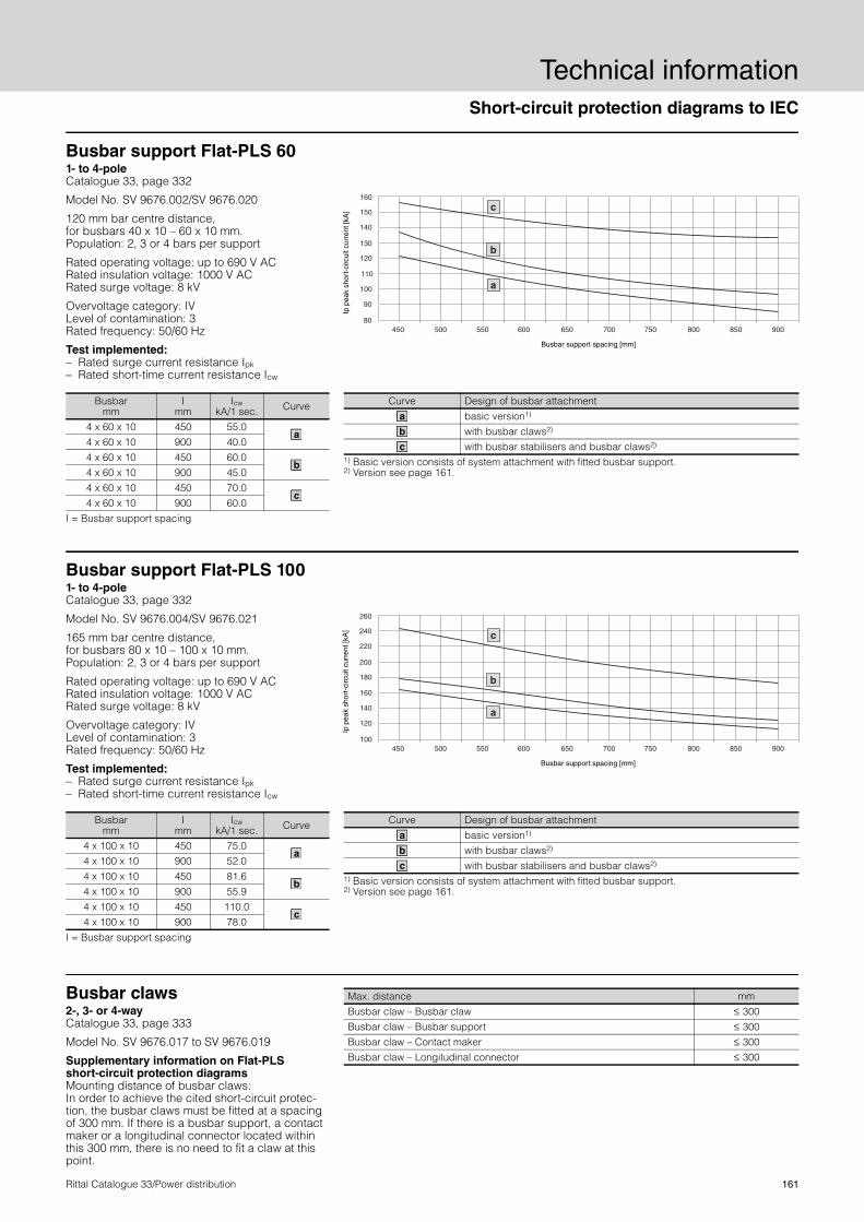
Busbar support Flat-PLS 601- to 4-pole Catalogue 33, page 332
Model No. SV 9676.002/SV 9676.020
120 mm bar centre distance, for busbars 40 x 10 – 60 x 10 mm.Population: 2, 3 or 4 bars per support
Rated operating voltage: up to 690 V ACRated insulation voltage: 1000 V ACRated surge voltage: 8 kV
Overvoltage category: IVLevel of contamination: 3 Rated frequency: 50/60 Hz
Test implemented:− Rated surge current resistance Ipk − Rated short-time current resistance Icw
Busbarmm
Imm
Icw kA/1 sec. Curve
4 x 60 x 10 450 55.0
4 x 60 x 10 900 40.0 4 x 60 x 10 450 60.0
4 x 60 x 10 900 45.0 4 x 60 x 10 450 70.0
4 x 60 x 10 900 60.0
I = Busbar support spacing
a
b
c
Ip p
eak
shor
t-ci
rcui
t cur
rent
[kA
] Busbar support spacing [mm]
Curve Design of busbar attachment basic version1) with busbar claws2) with busbar stabilisers and busbar claws2)
1) Basic version consists of system attachment with fitted busbar support. 2) Version see page 161.
a
b
c
260
240
220
200
180
160
120
140
100
a
c
b
450 500 550 600 650 700 750 800 850 900
Busbar support Flat-PLS 1001- to 4-pole Catalogue 33, page 332
Model No. SV 9676.004/SV 9676.021
165 mm bar centre distance, for busbars 80 x 10 – 100 x 10 mm.Population: 2, 3 or 4 bars per support
Rated operating voltage: up to 690 V ACRated insulation voltage: 1000 V ACRated surge voltage: 8 kV
Overvoltage category: IVLevel of contamination: 3 Rated frequency: 50/60 Hz
Test implemented:− Rated surge current resistance Ipk − Rated short-time current resistance Icw
Busbarmm
Imm
Icw kA/1 sec. Curve
4 x 100 x 10 450 75.0
4 x 100 x 10 900 52.0 4 x 100 x 10 450 81.6
4 x 100 x 10 900 55.9 4 x 100 x 10 450 110.0
4 x 100 x 10 900 78.0
I = Busbar support spacing
a
b
c
Ip p
eak
shor
t-ci
rcui
t cur
rent
[kA
]
Busbar support spacing [mm]
Curve Design of busbar attachment basic version1) with busbar claws2) with busbar stabilisers and busbar claws2)
1) Basic version consists of system attachment with fitted busbar support. 2) Version see page 161.
a
b
c
Busbar claws 2-, 3- or 4-way Catalogue 33, page 333
Model No. SV 9676.017 to SV 9676.019
Supplementary information on Flat-PLS short-circuit protection diagrams Mounting distance of busbar claws: In order to achieve the cited short-circuit protec-tion, the busbar claws must be fitted at a spacing of 300 mm. If there is a busbar support, a contact maker or a longitudinal connector located within this 300 mm, there is no need to fit a claw at this point.
Max. distance mmBusbar claw – Busbar claw 300Busbar claw – Busbar support 300Busbar claw – Contact maker 300Busbar claw – Longitudinal connector 300
<<<<

Technical informationShort-circuit protection diagrams to IEC
162 Rittal Catalogue 33/Power distribution
Laminated copper bars Catalogue 33, page 314
Configuration1) mm
In for
70 K2)
In for
50 K2)
In for
30 K2)
Curve (short-circuit resistance)
Installation type Model No. SV
8 x 6 x 0.5 195 A 165 A 125 A – – 3565.0156 x 9 x 0.8 285 A 240 A 180 A – – 3565.005
4 x 15.5 x 0.8 330 A 275 A 210 A – – 3567.0056 x 15.5 x 0.8 415 A 350 A 265 A 1 3568.005
10 x 15.5 x 0.8 575 A 480 A 365 A 1 3569.0055 x 20 x 1 525 A 435 A 330 A 1 3570.0055 x 24 x 1 605 A 510 A 385 A 1 3571.00510 x 24 x 1 920 A 770 A 585 A 1 3572.0055 x 32 x 1 770 A 645 A 485 A 2/3 3573.00510 x 32 x 1 1155 A 965 A 730 A 2/3 3574.0055 x 40 x 1 930 A 780 A 590 A 2/3 3575.00510 x 40 x 1 1370 A 1145 A 865 A 2/3 3576.0055 x 50 x 1 1125 A 940 A 710 A 2/3 3577.00510 x 50 x 1 1635 A 1365 A 1030 A 2/3 3578.00510 x 63 x 1 1950 A 1610 A 1230 A 2/3 3579.005
1) Number of lamina x lamina width x lamina thickness2) The conductor temperature of the laminated copper bar is derived by adding the ambient temperature and the
temperature increase together. Example: SV 3565.005 carrying 180 A, i.e. the temperature increases by 30 K. At an ambient temperature of 35°C, this produces a resultant conductor temperature of 35°C + 30 K = 65°C.
a
a
a
a
b
b
c
b
c
b
c
d
Basis of test:VDE 0660, part 500/IEC 60 439-1.Test implemented:Dynamic short-circuit resistance to IEC 60 439-1.
The dimensions for the support spacing (l) and for the centre-to-centre spacing (a) must be within the specified min./max. limits. The quotients of l/a can be used to determine the permissible short-circuit current Ip by using curves a to d. The prescribed installation type must be taken into account.
30
40
50
60
70
80
90
2.5 3.5 4.5 5.5 6.5 7.5 8.52 3 4 5 6 7 8 91.5
x
a
d
c
b
Ip s
hort
-circ
uit c
urre
nt [k
A]
Support spacing (l)Centre-to-centre spacing [a]
x =
Type of assembly with universal support SV 3079.000
l
a
1
l
a
2
a
l
3
CurveSupport spacing (l)
mmCentre-to-centre spacing (a)
mmmin. max. min. max.150 300 34 60150 350 42 85200 400 51 85200 450 81 100
a
w
c
d
Short-circuit resistance diagrams

Short-circuit protection diagrams to UL 508
Technical information
163Rittal Catalogue 33/Power distribution
The short-circuit resistance of Rittal RiLine60 has been extensively tested. Short-circuit resistance to UL criteria is assessed via the root-mean-square value of the short-circuit current (IRMS), which must be applied for at least 3 periods (60 ms).
During the course of testing, the test equip-ment has been adjusted to the respective root-mean-square values (IRMS). The result-ant peak short-circuit currents Ip are shown in the short-circuit protection diagrams below.
Busbar support for feeder circuits 700 A, 3-pole Catalogue 33, page 276
60 mm bar centre distance, for busbars 15 x 5 – 30 x 10 mm.
Note:SV 9340.050 with E-Cu 30 x 5/10 mm With a pre-fuse, the following short-circuit value can be achieved: − Support spacing: 350 mm− Fuse: Class L 800 A − IRMS: 50 kA
200 250 450350 400300 600500 550
30
35
45
40
60
65
55
50
70
80
75
25
20
Ip p
eak
shor
t-ci
rcui
t cur
rent
[kA
]
Busbar support spacing [mm]
Support spacing mm
IRMS kA
250 30500 22
20
25
35
30
450300200 250 350 400 550500 600
80
75
70
65
60
55
50
45
40
Ip p
eak
shor
t-ci
rcui
t cur
rent
[kA
]
Busbar support spacing [mm]
SV 9340.050 with 30 x 5/10 mm
SV 9340.050 with 25 x 5 mm20 x 5/10 mm15 x 5/15 mm
Settings IRMS (Ieff.) of the test equipment without pre-fuse:
Support spacing mm
IRMS kA
250 35500 25
Busbar support for feeder circuits 700 A (PLS 800)/1400 A (PLS 1600), 3-pole Catalogue 33, page 278/279
60 mm bar centre distance, for PLS special busbars.
Note:SV 9342.050 (PLS 1600) With a pre-fuse, the following short-circuit value can be achieved: − Support spacing: 250 mm − Fuse: Class L 1400 A − IRMS: 65 kA
30
25
20
65
60
55
45
35
40
50
80
75
70
350200 250 300 450400 500 550150450
20
25
30
200 250 300 350 400
50
40
35
45
55
60
65
500
70
75
80
550150
Ip p
eak
shor
t-ci
rcui
t cur
rent
[kA
]
Busbar support spacing [mm]
Support spacing mm
IRMS kA
150 35500 25
Ip p
eak
shor
t-ci
rcui
t cur
rent
[kA
]
Busbar support spacing [mm]
SV 9341.050 (PLS 800) SV 9342.050 (PLS 1600)
Settings IRMS (Ieff.) of the test equipment without pre-fuse:
Support spacing mm
IRMS kA
200 22500 14

Technical informationShort-circuit protection diagrams to UL 508/System data
164 Rittal Catalogue 33/Power distribution
Busbar support for feeder circuits up to 700 A, 4-pole Catalogue 33, page 277
Model No. SV 9340.004/SV 9342.014
60 mm bar centre distance.
Settings IRMS (Ieff.) of the test equipment with-out pre-fuse:
Model No. SV
Busbarmm
Support spacing
mmIRMS
9340.004 15 x 5 – 30 x 10
250 30500 22
9342.014 30 x 10250 42500 25
a
b
Ip p
eak
shor
t-ci
rcui
t cur
rent
[kA
]
Busbar support spacing [mm]
60
55
50
45
40
35
30
25
20
200 250 400350300 450 500
65
70
75
80
85
90
95
100
105
110
115
b
a
Busbar support for feeder circuits up to 1400 A, 4-pole Catalogue 33, page 279
Model No. SV 9342.004
60 mm bar centre distance, for PLS special busbars.
Settings IRMS (Ieff.) of the test equipment without pre-fuse:
Busbarmm
Support spacing
mm
RMSkA
PLS 1600150 35500 25
30
25
20
65
60
55
45
35
40
50
80
75
70
350200 250 300 450400 500 550150
Ip p
eak
shor
t-ci
rcui
t cur
rent
[kA
]
Busbar support spacing [mm]
Operating and ambient conditions for Ri4Power switchgear assembliesPage 165 – 171
The siting conditions for Ri4Power systems are identical for all field types. Any require-ments which deviate from this should be agreed with the product management team.
Additional field-specific technical data for the tested field types is listed in detail on the following pages. This data represents the maximum, tested figures.
For optimum adaptation of customer require-ments to the possible system assemblies, we recommend use of the latest version of the Rittal Power Engineering software.
Operating and ambient conditions
Ambient temperature
Short-term peak +40°CEN 61 439-1EN 61 439-2Maximum on a 24 h average +35°C
Low –5°C
Atmospheric conditions
Normal climatic stress
EN 61 439-1EN 61 439-2Relative humidity
50% at 40°C 90% at 20°C (without condensation due to temperature fluctuations)Operation up to 1000 m above sea level

System data
Technical information
165Rittal Catalogue 33/Power distribution
ISV-TS 8 enclosuresfor distribution enclosures up to 1600 A Catalogue 33, page 83
Busbar system Maxi-PLS 1600 Flat copper 80 x 10 mm
Electrical characteristics
Rated voltage
Rated insulation voltage Ui 1000 V
EN 61 439-1/-2
Rated operating voltage Ue 690 VRated surge voltage resistance Uimp 8 kVOvervoltage category IVLevel of contamination 3Rated frequency 50 Hz
Rated current (primary busbar)
Rated operating current Ie 1300 A 1200 A For IP 55 1600 A 1500 A For IP 1X1) 1600 A 1600 A For IP 542)
Rated surge current resistance Ipk 105 kAEN 61 439-1/-2
Rated short-time current resistance Icw 50 kA
Mechanical characteristics
Dimensions
Enclosure width Enclosure height Enclosure depth
600/850 mm 2000 mm3) 600 mm3)
Pitch pattern 25 mmProtection category Max. IP 55 IEC 60 529Design 1 EN 61 439-1/-2
Surface protection/Material
Enclosure frame Dipcoat-primed
Panels (roof plate, rear panel) Dipcoat-primed, powder-coated in RAL 7035 on the outside
System attachment Stainless steelSystem rails and punched sections with mounting flanges Sheet steel, zinc-plated
BusbarMaterial E-Cu, bareExternal dimensions (cross-section) 45 x 45 mm (1000 mm2) 80 x 10 mm
Operating and ambient conditions
Ambient temperature
Short-term peak +40°CEN 61 439-1/-2Maximum on a 24 h average +35°C
Low –5°C
Atmospheric conditions
Normal climatic stressEN 61 439-1/-2Relative humidity 50% at 40°C
Operation up to 1000 m above sea level1) Using spacer DK 7967.000 for raising the roof. 2) Using fan-and-filter unit SK 3243.100 (500 m3/h) and outlet filter SK 3243.200. 3) Other sizes available on request
Technical informationSystem data
166 Rittal Catalogue 33/Power distribution
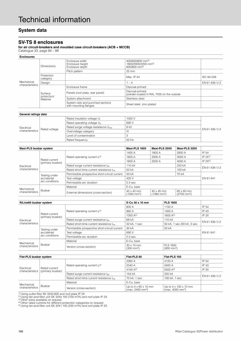
SV-TS 8 enclosures for air circuit-breakers and moulded case circuit-breakers (ACB + MCCB) Catalogue 33, page 84 – 88
Enclosures
Mechanical characteristics
Dimensions
Enclosure width Enclosure height Enclosure depth
400/600/800 mm3) 1800/2000/2200 mm3) 600/800 mm3)
Pitch pattern 25 mmProtection category Max. IP 54 IEC 60 529
Design 1 – 4 EN 61 439-1/-2
Surface protection/Material
Enclosure frame Dipcoat-primed
Panels (roof plate, rear panel) Dipcoat-primed, powder-coated in RAL 7035 on the outside
System attachment Stainless steelSystem rails and punched sections with mounting flanges Sheet steel, zinc-plated
General ratings data
Electrical characteristics Rated voltage
Rated insulation voltage Ui 1000 V
EN 61 439-1/-2
Rated operating voltage Ue 690 VRated surge voltage resistance Uimp 8 kVOvervoltage category IVLevel of contamination 3Rated frequency 50 Hz
Maxi-PLS busbar system Maxi-PLS 1600 Maxi-PLS 2000 Maxi-PLS 3200
Electrical characteristics
Rated current (primary busbar)
Rated operating current Ie4) 1400 A 1800 A 2800 A IP 54 1600 A 2000 A 3000 A IP 2X1) 1800 A 2500 A 4000 A IP 2X2)
Rated surge current resistance Ipk 110 kA 220 kA EN 61 439-1/-2
Rated short-time current resistance Icw 50 kA 100 kA
Testing under accidental arc conditions
Permissible prospective short-circuit current 50 kA 70 kAEN 61 641 Test voltage 420 V
Permissible arc duration 0.3 sec.
Mechanical characteristics Busbar
Material E-Cu, bare
External dimensions (cross-section) 45 x 45 mm (1000 mm2)
45 x 45 mm (1380 mm2)
60 x 60 mm (2700 mm2)
RiLine60 busbar system E-Cu 30 x 10 mm PLS 1600
Electrical characteristics
Rated current (primary busbar)
Rated operating current Ie4) 800 A 1150 A IP 54 860 A 1300 A IP 43 1000 A5) 1600 A2) IP 2X
Rated surge current resistance Ipk 68 kA 110 kAEN 61 439-1/-2
Rated short-time current resistance Icw 32 kA, 1 sec. 50 kA, 1 sec./50 kA, 3 sec.
Testing under accidental arc conditions
Permissible prospective short-circuit current 30 kA 50 kAEN 61 641 Test voltage 690 V
Permissible arc duration 0.3 sec.
Mechanical characteristics Busbar
Material E-Cu, bare
Version (cross-section) 30 x 10 mm (300 mm2)
PLS 1600 (900 mm2)
Flat-PLS busbar system Flat-PLS 60 Flat-PLS 100
Electrical characteristics
Rated current (primary busbar)
Rated operating current Ie4) 2360 A 3120 A IP 54 2540 A 3400 A IP 43 4100 A2) 5500 A2) IP 2X
Rated surge current resistance Ipk 154 kA 220 kAEN 61 439-1/-2
Rated short-time current resistance Icw 70 kA, 1 sec. 100 kA, 1 sec.
Mechanical characteristics Busbar
Material E-Cu, bare
Version (cross-section) Up to 4 x 60 x 10 mm (max. 2400 mm2)
Up to 4 x 100 x 10 mm (max. 4000 mm2)
1) Using outlet filter SK 3243.600 and roof plate IP 2X. 2) Using fan-and-filter unit SK 3244.100 (700 m3/h) and roof plate IP 2X. 3) Other sizes available on request. 4) Other rated currents for different protection categories on request. 5) Using fan-and-filter unit SK 3241.100 (230 m3/h) and roof plate IP 2X.

System data
Technical information
167Rittal Catalogue 33/Power distribution
SV-TS 8 enclosures for coupling sections Catalogue 33, page 84 – 88
Enclosures
Mechanical characteristics
Dimensions
Enclosure width Enclosure height Enclosure depth
600/800/1000 mm3) 2000/2200 mm3) 600/800 mm3)
Pitch pattern 25 mmProtection category Max. IP 54 IEC 60 529
Design 1 – 4 EN 61 439-1/-2
Surface protection/Material
Enclosure frame Dipcoat-primed
Panels (roof plate, rear panel) Dipcoat-primed, powder-coated in RAL 7035 on the outside
System attachment Stainless steelSystem rails and punched sections with mounting flanges Sheet steel, zinc-plated
General ratings data
Electrical characteristics Rated voltage
Rated insulation voltage Ui 1000 V
EN 61 439-1/-2
Rated operating voltage Ue 690 VRated surge voltage resistance Uimp 8 kVOvervoltage category IVLevel of contamination 3Rated frequency 50 Hz
Maxi-PLS busbar system Maxi-PLS 1600 Maxi-PLS 2000 Maxi-PLS 3200
Electrical characteristics
Rated current (primary busbar)
Rated operating current Ie4) 1400 A 1800 A 2800 A For IP 541600 A 2000 A 3000 A For IP 2X1) 1800 A 2500 A 4000 A For IP 2X2)
Rated surge current resistance Ipk 110 kA 165 kAEN 61 439-1/-2
Rated short-time current resistance Icw 50 kA 75 kA
Testing under accidental arc conditions
Permissible prospective short-circuit current 50 kA 70 kAEN 61 641Test voltage 420 V
Permissible arc duration 0.3 sec.
Mechanical characteristics Busbar
Material E-Cu, bare
External dimensions (cross-section) 45 x 45 mm(1000 mm2)
45 x 45 mm(1380 mm2)
60 x 60 mm (2700 mm2)
RiLine60 busbar system E-Cu 30 x 10 mm PLS 1600
Electrical characteristics
Rated current (primary busbar)
Rated operating current Ie4) 800 A 1150 A IP 54 860 A 1300 A IP 43 1000 A5) 1600 A2) IP 2X
Rated surge current resistance Ipk 68 kA 110 kAEN 61 439-1/-2
Rated short-time current resistance Icw 32 kA, 1 sec. 50 kA, 1 sec./50 kA, 3 sec.
Testing under accidental arc conditions
Permissible prospective short-circuit current 30 kA 50 kAEN 61 641
Test voltage 690 VPermissible arc duration 0.3 sec.
Mechanical characteristics Busbar
Material E-Cu, bare
Version (cross-section) 30 x 10 mm (300 mm2)
PLS 1600 (900 mm2)
Flat-PLS busbar system Flat-PLS 60 Flat-PLS 100
Electrical characteristics
Rated current (primary busbar)
Rated operating current Ie4) 2360 A 3120 A IP 542540 A 3400 A IP 434100 A2) 5500 A2) IP 2X
Rated surge current resistance Ipk 154 kA 220 kAEN 61 439-1/-2
Rated short-time current resistance Icw 70 kA, 1 sec. 100 kA, 1 sec.
Mechanical characteristics Busbar
Material E-Cu, bare
Version (cross-section) Up to 4 x 60 x 10 mm (max. 2400 mm2)
Up to 4 x 100 x 10 mm (max. 4000 mm2)
1) Using outlet filter SK 3243.600 and roof plate IP 2X. 2) Using fan-and-filter unit SK 3244.100 (700 m3/h) and roof plate IP 2X. 3) Other sizes available on request. 4) Other rated currents for different protection categories on request. 5) Using fan-and-filter unit SK 3241.100 (230 m3/h) and roof plate IP 2X.

Technical informationSystem data
168 Rittal Catalogue 33/Power distribution
SV-TS 8 enclosures for modular outgoing sections Catalogue 33, page 86 – 88
Enclosures
Mechanical characteristics
Dimensions
Enclosure width Enclosure height Enclosure depth
400/600/800 mm3) 1800/2000/2200 mm3) 600/800 mm3)
Pitch pattern 25 mmProtection category Max. IP 54 IEC 60 529
Design 1 – 4 EN 61 439-1/-2
Surface protection/Material
Enclosure frame Dipcoat-primed Panels (roof plate, rear panel) Dipcoat-primed, powder-coated in RAL 7035 on the outsideSystem attachment Stainless steelSystem rails and punched sections with mounting flanges Sheet steel, zinc-plated
General ratings data
Electrical characteristics Rated voltage
Rated insulation voltage Ui 1000 V
EN 61 439-1/-2
Rated operating voltage Ue 690 VRated surge voltage resistance Uimp 8 kVOvervoltage category IVLevel of contamination 3Rated frequency 50 Hz
Maxi-PLS busbar system Maxi-PLS 1600 Maxi-PLS 2000 Maxi-PLS 3200
Electrical characteristics
Rated current (primary busbar)
Rated operating current Ie4) 1400 A 1800 A 2800 A For IP 541600 A 2000 A 3000 A For IP 2X1) 1800 A 2500 A 4000 A For IP 2X2)
Rated surge current resistance Ipk 110 kA 220 kA EN 61 439-1/-2
Rated short-time current resistance Icw 50 kA 100 kA
Testing under accidental arc conditions
Permissible prospective short-circuit current 50 kA 70 kA EN 61 641 Test voltage 690 V
Permissible arc duration 0.3 sec.
Mechanical characteristics Busbar
Material E-Cu, bare
External dimensions (cross-section) 45 x 45 mm (1000 mm2)
45 x 45 mm (1380 mm2)
60 x 60 mm (2700 mm2)
RiLine60 busbar system E-Cu 30 x 10 mm PLS 1600
Electrical characteristics
Rated current (primary busbar)
Rated operating current Ie4) 800 A 1150 A IP 54 860 A 1300 A IP 43 1000 A5) 1600 A2) IP 2X
Rated surge current resistance Ipk 68 kA 110 kAEN 61 439-1/-2
Rated short-time current resistance Icw 32 kA, 1 sec. 50 kA, 1 sec./50 kA, 3 sec.
Rated current (distribution busbar)
Rated operating current Ie4) 800 A 1600 A6) IP 54 860 A 1600 A6) IP 43 1000 A5) 1600 A2) IP 2X
Rated surge current resistance Ipk 68 kA 110 kAEN 61 439-1/-2
Rated short-time current resistance Icw 32 kA, 1 sec. 50 kA, 1 sec./50 kA, 3 sec.
Testing under accidental arc conditions
Permissible prospective short-circuit current 30 kA 50 kAEN 61 641 Test voltage 690 V
Permissible arc duration 0.3 sec.
Mechanical characteristics Busbar
Material E-Cu, bareVersion (cross-section) 30 x 10 mm (300 mm2) PLS 1600 (900 mm2)
Flat-PLS busbar system Flat-PLS 60 Flat-PLS 100
Electrical characteristics
Rated current (primary busbar)
Rated operating current Ie4) 2360 A 3120 A IP 54 2540 A 3400 A IP 43 4100 A2) 5500 A2) IP 2X
Rated surge current resistance Ipk 154 kA 220 kARated short-time current resistance Icw 70 kA, 1 sec. 100 kA, 1 sec.
Mechanical characteristics Busbar
Material E-Cu, bare
Version (cross-section) Up to 4 x 60 x 10 mm (max. 2400 mm2)
Up to 4 x 100 x 10 mm (max. 4000 mm2)
1) Using outlet filter SK 3243.600 and roof plate IP 2X. 2) Using fan-and-filter unit SK 3244.100 (700 m3/h) and roof plate IP 2X. 3) Other sizes available on request. 4) Other rated currents for different protection categories on request. 5) Using fan-and-filter unit SK 3241.100 (230 m3/h) and roof plate IP 2X. 6) In conjunction with RiLine60 as the main busbar system: Rated currents on request.

System data
Technical information
169Rittal Catalogue 33/Power distribution
SV-TS 8 enclosures for switch-disconnector-fuse sections Catalogue 33, page 91/92
Enclosures
Mechanical characteristics
Dimensions
Enclosure width Enclosure height Enclosure depth
1000/1200 mm3) 2000/2200 mm3) 600/800 mm3)
Pitch pattern 25 mmProtection category Max. IP 31 IEC 60 529
Design 1 – 4 EN 61 439-1/-2
Surface protection/Material
Enclosure frame Dipcoat-primed
Panels (roof plate, rear panel) Dipcoat-primed, powder-coated in RAL 7035 on the outside
System attachment Stainless steelSystem rails and punched sections with mounting flanges Sheet steel, zinc-plated
General ratings data
Electrical characteristics Rated voltage
Rated insulation voltage Ui 1000 V
EN 61 439-1/-2
Rated operating voltage Ue 690 VRated surge voltage resistance Uimp 8 kVOvervoltage category IVLevel of contamination 3Rated frequency 50 Hz
Maxi-PLS busbar system Maxi-PLS 1600 Maxi-PLS 2000 Maxi-PLS 3200
Electrical characteristics
Rated current (primary busbar)
Rated operating current Ie4) 1400 A 1800 A 2800 A For IP 541800 A 2500 A 4000 A For IP 2X1)
Rated surge current resistance Ipk 110 kA 220 kA EN 61 439-1/-2
Rated short-time current resistance Icw 50 kA 100 kA
Testing under accidental arc conditions
Permissible prospective short-circuit current 50 kA 70 kA EN 61 641 Test voltage 690 V
Permissible arc duration 0.3 sec.
Mechanical characteristics Busbar
Material E-Cu, bare
External dimensions (cross-section) 45 x 45 mm (1000 mm2)
45 x 45 mm (1380 mm2)
60 x 60 mm (2700 mm2)
Flat-PLS busbar system Flat-PLS 60 Flat-PLS 100
Electrical characteristics
Rated current (primary busbar)
Rated operating current Ie4) 2360 A 3120 A IP 542540 A 3400 A IP 434100 A2) 5500 A IP 2X
Rated surge current resistance Ipk 154 kA 220 kAEN 61 439-1/-2
Rated short-time current resistance Icw 70 kA, 1 sec. 100 kA, 1 sec.
Mechanical characteristics Busbar
Material E-Cu, bare
Version (cross-section) Up to 4 x 60 x 10 mm (max. 2400 mm2)
Up to 4 x 100 x 10 mm (max. 4000 mm2)
Flat-PLS distribution busbar system Flat-PLS
Electrical characteristics
Rated current (distribution busbar)
Rated operating current Ie4) 1000 A 1250 A 1600 A 2100 A IP 31 Rated surge current resistance Ipk 154 kA 165 kA 187 kA 220 kA
EN 61 439-1/-2 Rated short-time current resistance Icw 70 kA,
1 sec. 75 kA, 1 sec.
85 kA, 1 sec.
100 kA, 1 sec.
Mechanical characteristics Busbar
Material E-Cu, bare
Version (cross-section) 50 x 10 mm (500 mm2)
60 x 10 mm (600 mm2)
80 x 10 mm (800 mm2)
100 x 10 mm (1000 mm2)
1) Using roof plate IP 2X. 2) Using fan-and-filter unit SK 3244.100 (700 m3/h) and roof plate IP 2X. 3) Other sizes available on request. 4) Other rated currents for different protection categories on request.

Technical informationSystem data
170 Rittal Catalogue 33/Power distribution
SV-TS 8 enclosures for cable chambers Catalogue 33, page 89/90
Enclosures
Mechanical characteristics
Dimensions
Enclosure width Enclosure height Enclosure depth
300/400/600 mm3) 1800/2000/2200 mm3) 600/800 mm3)
Pitch pattern 25 mmProtection category Max. IP 54 IEC 60 529
Design 1 – 4 EN 61 439-1/-2
Surface protection/Material
Enclosure frame Dipcoat-primed
Panels (roof plate, rear panel) Dipcoat-primed, powder-coated in RAL 7035 on the outside
System attachment Stainless steelSystem rails and punched sections with mounting flanges Sheet steel, zinc-plated
Maxi-PLS busbar system Maxi-PLS 1600 Maxi-PLS 2000 Maxi-PLS 3200
Electrical characteristics
Rated current (primary busbar)
Rated operating current Ie4) 1400 A 1800 A 2800 A For IP 541600 A 2000 A 3000 A For IP 2X1) 1800 A 2500 A 4000 A For IP 2X2)
Rated surge current resistance Ipk 110 kA 220 kA EN 61 439-1/-2
Rated short-time current resistance Icw 50 kA 100 kA
Testing under accidental arc conditions
Permissible prospective short-circuit current 50 kA 70 kA EN 61 641 Test voltage 420 V
Permissible arc duration 0.3 sec.
Mechanical characteristics Busbar
Material E-Cu, bare
External dimensions (cross-section) 45 x 45 mm (1000 mm2)
45 x 45 mm (1380 mm2)
60 x 60 mm(2700 mm2)
RiLine60 busbar system E-Cu 30 x 10 mm PLS 1600
Electrical characteristics
Rated current (primary busbar)
Rated operating current Ie4) 800 A 1150 A IP 54 860 A 1300 A IP 43 1000 A5) 1600 A2) IP 2X
Rated surge current resistance Ipk 68 kA 110 kAEN 61 439-1/-2
Rated short-time current resistance Icw 32 kA, 1 sec. 50 kA, 1 sec./50 kA, 3 sec.
Testing under accidental arc conditions
Permissible prospective short-circuit current 30 kA 50 kAEN 61 641 Test voltage 690 V
Permissible arc duration 0.3 sec.
Mechanical characteristics Busbar
Material E-Cu, bare
Version (cross-section) 30 x 10 mm (300 mm2)
PLS 1600 (900 mm2)
Flat-PLS busbar system Flat-PLS 60 Flat-PLS 100
Electrical characteristics
Rated current (primary busbar)
Rated operating current Ie4) 2360 A 3120 A IP 542540 A 3400 A IP 434100 A2) 5500 A2) IP 2X
Rated surge current resistance Ipk 154 kA 220 kAEN 61 439-1/-2
Rated short-time current resistance Icw 70 kA, 1 sec. 100 kA, 1 sec.
Mechanical characteristics Busbar
Material E-Cu, bare
Version (cross-section) Up to 4 x 60 x 10 mm (max. 2400 mm2)
Up to 4 x 100 x 10 mm (max. 4000 mm2)
1) Using outlet filter SK 3243.600 and roof plate IP 2X. 2) Using fan-and-filter unit SK 3244.100 (700 m3/h) and roof plate IP 2X. 3) Other sizes available on request. 4) Other rated currents for different protection categories on request. 5) Using fan-and-filter unit SK 3241.100 (230 m3/h) and roof plate IP 2X.

System data
Technical information
171Rittal Catalogue 33/Power distribution
SV-TS 8 enclosures for busbar sections Catalogue 33, page 89/90, 93
Enclosures
Mechanical characteristics
Dimensions
Enclosure width Enclosure height Enclosure depth
200/300/400 mm3) 1800/2000/2200 mm3) 600/800 mm3)
Pitch pattern 25 mmProtection category Max. IP 54 IEC 60 529
Design 1 – 4 EN 61 439-1/-2
Surface protection/Material
Enclosure frame Dipcoat-primed
Panels (roof plate, rear panel) Dipcoat-primed, powder-coated in RAL 7035 on the outside
System attachment Stainless steelSystem rails and punched sectionswith mounting flanges Sheet steel, zinc-plated
General ratings data
Electrical characteristics Rated voltage
Rated insulation voltage Ui 1000 V
EN 61 439-1/-2
Rated operating voltage Ue 690 VRated surge voltage resistance Uimp 8 kVOvervoltage category IVLevel of contamination 3Rated frequency 50 Hz
Maxi-PLS busbar system6) Maxi-PLS 1600 Maxi-PLS 2000 Maxi-PLS 3200
Electrical characteristics
Rated current (primary busbar)
Rated operating current Ie4) 1400 A 1800 A 2800 A For IP 541600 A 2000 A 3000 A For IP 2X1) 1800 A 2500 A 4000 A For IP 2X2)
Rated surge current resistance Ipk 110 kA 165 kA EN 61 439-1/-2
Rated short-time current resistance Icw 50 kA 75 kA
Testing under accidental arc conditions
Permissible prospective short-circuit current 50 kA 70 kA EN 61 641 Test voltage 420 V
Permissible arc duration 0.3 sec.
Mechanical characteristics Busbar
Material E-Cu, bare
External dimensions (cross-section) 45 x 45 mm (1000 mm2)
45 x 45 mm (1380 mm2)
60 x 60 mm(2700 mm2)
RiLine60 busbar system6) E-Cu 30 x 10 mm PLS 1600
Electrical characteristics
Rated current (primary busbar)
Rated operating current Ie4) 800 A 1150 A IP 54 860 A 1300 A IP 43 1000 A5) 1600 A2) IP 2X
Rated surge current resistance Ipk 68 kA 110 kAEN 61 439-1/-2
Rated short-time current resistance Icw 32 kA, 1 sec. 50 kA, 1 sec./50 kA, 3 sec.
Testing under accidental arc conditions
Permissible prospective short-circuit current 30 kA 50 kAEN 61 641 Test voltage 690 V
Permissible arc duration 0.3 sec.
Mechanical characteristics Busbar
Material E-Cu, bare
Version (cross-section) 30 x 10 mm (300 mm2)
PLS 1600 (900 mm2)
Flat-PLS busbar system6) Flat-PLS 60 Flat-PLS 100
Electrical characteristics
Rated current (primary busbar)
Rated operating current Ie4) 2360 A 3120 A IP 54 2540 A 3400 A IP 43 4100 A2) 5500 A2) IP 2X
Rated surge current resistance Ipk 154 kA 220 kARated short-time current resistance Icw 70 kA, 1 sec. 100 kA, 1 sec.
Mechanical characteristics Busbar
Material E-Cu, bare
Version (cross-section) Up to 4 x 60 x 10 mm (max. 2400 mm2)
Up to 4 x 100 x 10 mm (max. 4000 mm2)
1) Using outlet filter SK 3243.600 and roof plate IP 2X. 2) Using fan-and-filter unit SK 3244.100 (700 m3/h) and roof plate IP 2X. 3) Other sizes available on request. 4) Other rated currents for different protection categories on request. 5) Using fan-and-filter unit SK 3241.100 (230 m3/h) and roof plate IP 2X.6) Usability of the various busbar systems depends on the enclosure width.

Technical informationOverview of approvals and assembly data for applications to UL (RiLine60)
172 Rittal Catalogue 33/Power distribution
Model No. SV
E191125
E235931
E191125
E235931
E195144
Rated current
Rated voltage
Connection cross-sections
Tightening torqueRound
conductorsLaminated copper bar Others
3086.000 � 3087.000 � 3088.000 � 3090.000 � 3091.000 � 3092.000 � 3450.500 � 1 – 4 mm2 3451.500 � 2.5 – 16 mm2 3452.500 � 16 – 50 mm2 3453.500 � 35 – 70 mm2 3454.500 � 70 – 185 mm2 3455.500 � 1 – 4 mm2 3456.500 � 2.5 – 16 mm2 3457.500 � 16 – 50 mm2 3458.500 � 35 – 70 mm2 3459.500 � 70 – 185 mm2 3460.500 � 3504.000 � CMS 15 Nm 3505.000 � CMS 15 Nm 3509.000 � 700 A3514.000 � CMS 20 Nm 3515.000 � CMS 20 Nm 3516.000 � 1400 A3524.000 � 700 A3525.000 � 700 A3525.010 � 700 A3526.000 � 700 A3527.000 � 1400 A3528.000 � 1400 A3528.010 � 1400 A3529.000 � 1400 A3548.000 � 3549.000 � 3550.000 � 1 – 4 mm2 3555.000 � 1 – 4 mm2 3563.000 � 3580.000 � 140 A3580.100 � 280 A3581.000 � 175 A3581.100 � 350 A3582.000 � 230 A3583.000 � 290 A3584.000 � 350 A3585.000 � 465 A3586.000 � 700 A9320.020 � 9320.030 � 9320.040 � 9320.050 � 9320.060 � 9320.070 � 9320.090 � 9320.120 � 9320.150 �
9340.004 � BMS 3 NmCMS 5 Nm
9340.050 � BMS 3 NmCMS 5 Nm
9340.070 � 9340.074 � 9340.100 � 9340.110 �
Listed components for feeder-circuits up to 600 V AC TS = terminal screw CCC = Conductor connection clamp CMS = Component mounting screw BMS = Busbar mounting screw Conversion factor: 1 Nm = 8.851 in-lbs s = stranded sol = solid Lam. Cu = Laminated copper bar (Flexibar)

Overview of approvals and assembly data for applications to UL (RiLine60)
Technical information
173Rittal Catalogue 33/Power distribution
9340.120 � 9340.130 � 9340.134 � 9340.140 � 9340.200 � 9340.210 � 9340.214 � 9340.220 � 9340.224 � 9340.260 � 9340.270 � 9340.280 � 9340.290 � 9340.310 � 25 A 600 V AC AWG 129340.340 � 25 A 600 V AC AWG 129340.350 � 30 A 600 V AC AWG 109340.370 � 25 A 600 V AC AWG 129340.380 � 30 A 600 V AC AWG 109340.410 � 60 A 600 V AC AWG 69340.430 � 60 A 600 V AC AWG 69340.450 � 60 A 600 V AC AWG 69340.460 � 30 A 600 V AC AWG 109340.470 � 30 A 600 V AC AWG 109340.700 � 60 A 600 V AC AWG 69340.710 � 40 A 600 V AC AWG 8
9341.050 � BMS 0.7 NmCMS 5 Nm
9341.070 � 9341.100 � 9341.110 � 9341.120 � 9341.130 � 9341.140 �
9342.004 � BMS 7 NmCMS 5 Nm
9342.014 � BMS 7 NmCMS 5 Nm
9342.050 � BMS 0.7 Nm9342.070 � 9342.074 � 9342.100 � 9342.110 � 9342.120 � 9342.130 � 9342.134 � 9342.140 � 9342.200 � 60 A 600 V AC AWG 6 – 10 5 Nm9342.210 � 60 A 600 V AC AWG 6 – 10 5 Nm9342.220 � 125 A 600 V AC AWG 2 – 6 5 Nm 9342.224 � 125 A 600 V AC AWG 2 – 6 5 Nm 9342.230 � 125 A 600 V AC AWG 2 – 6 5 Nm9342.234 � 125 A 600 V AC AWG 2 – 6 5 Nm9342.240 � 125 A 600 V AC AWG 2 – 6 5 Nm9342.244 � 125 A 600 V AC AWG 2 – 6 5 Nm9342.250 � 250 A 600 V AC AWG 2 – MCM 250 12 Nm 12 Nm9342.254 � 250 A 600 V AC AWG 2 – MCM 250 12 Nm 12 Nm9342.260 � 250 A 600 V AC AWG 2 – MCM 250 12 Nm 12 Nm9342.270 � 250 A 600 V AC AWG 2 – MCM 250 12 Nm 12 Nm9342.274 � 250 A 600 V AC AWG 2 – MCM 250 12 Nm 12 Nm9342.280 � 600 A 600 V AC AWG 4/0 – MCM 600 18 Nm 18 Nm9342.290 � 600 A 600 V AC AWG 4/0 – MCM 600 18 Nm 18 Nm
Listed components for feeder-circuits up to 600 V AC TS = terminal screw CCC = Conductor connection clamp CMS = Component mounting screw BMS = Busbar mounting screw Conversion factor: 1 Nm = 8.851 in-lbs s = stranded sol = solid Lam. Cu = Laminated copper bar (Flexibar)
Model No. SV
E191125
E235931
E191125
E235931
E195144
Rated current
Rated voltage
Connection cross-sections
Tightening torqueRound
conductorsLaminated copper bar Others

Technical informationOverview of approvals and assembly data for applications to UL (RiLine60)
174 Rittal Catalogue 33/Power distribution
9342.300 � 600 A 600 V AC AWG 4/0 – MCM 600Lam. E-Cu 10 x 32 x 1 18 Nm 18 Nm
9342.310 � 700 A 600 V AC AWG 4/0 – MCM 600Lam. E-Cu 10 x 32 x 1 16.5 Nm 16.5 Nm
9342.314 � 700 A 600 V AC AWG 4/0 – MCM 600Lam. E-Cu 10 x 32 x 1 16.5 Nm 16.5 Nm
9342.320 � 1400 A 600 V AC Lam. Cu 10 x 63 x 1 mm – 22 Nm
9342.324 � 1400 A 600 V AC – 22 Nm9342.400 � 100 A 600 V AC AWG 2 – 6 5 Nm – 9342.410 � 100 A 600 V AC AWG 2 – 6 5 Nm –
9342.504 � 125 A 600 V ACAWG 2 – MCM 250
Lam. Cu 10 x 15.5 x 0.8 mm
12 Nm 12 Nm
9342.514 � 125 A 600 V ACAWG 2 – MCM 250
Lam. Cu 10 x 15.5 x 0.8 mm
12 Nm 12 Nm
9342.540 � 125 A 600 V ACAWG 2 – MCM 250
Lam. Cu 10 x 15.5 x 0.8 mm
12 Nm 12 Nm
9342.550 � 125 A 600 V ACAWG 2 – MCM 250
Lam. Cu 10 x 15.5 x 0.8 mm
12 Nm 12 Nm
9342.600 � 250 A 600 V ACAWG 2 – MCM 250
Lam. Cu 10 x 15.5 x 0.8 mm
12 Nm 12 Nm
9342.604 � 250 A 600 V ACAWG 2 – MCM 250
Lam. Cu 10 x 15.5 x 0.8 mm
12 Nm 12 Nm
9342.610 � 250 A 600 V ACAWG 2 – MCM 250
Lam. Cu 10 x 15.5 x 0.8 mm
12 Nm 12 Nm
9342.614 � 250 A 600 V ACAWG 2 – MCM 250
Lam. Cu 10 x 15.5 x 0.8 mm
12 Nm 12 Nm
9342.700 � 600 A 600 V AC Lam. Cu 10 x 32 x 1 mm 30 Nm 30 Nm
9342.710 � 600 A 600 V AC Lam. Cu 10 x 32 x 1 mm 30 Nm 30 Nm
9342.720 � 9343.000 � 1) 160 A 600 V AC CCC: 4.5 Nm CCC: 4.5 Nm CMS 6 Nm9343.010 � 1) 160 A 600 V AC TS: 12 Nm TS: 12 Nm CMS 6 Nm9343.100 � 1) 250 A 600 V AC CCC: 12 Nm CCC: 12 Nm CMS 6 Nm9343.110 � 1) 250 A 600 V AC TS: 20 Nm TS: 20 Nm CMS 6 Nm9343.200 � 1) 400 A 600 V AC CCC: 20 Nm CCC: 20 Nm CMS 8 Nm9343.210 � 1) 400 A 600 V AC TS: 20 Nm TS: 20 Nm CMS 8 Nm9343.300 � 1) 630 A 600 V AC CCC: 20 Nm CCC: 20 Nm CMS 8 Nm9343.310 � 1) 630 A 600 V AC TS: 20 Nm TS: 20 Nm CMS 8 Nm9344.000 � 1) 160 A 600 V AC CCC: 4.5 Nm CCC: 4.5 Nm9344.010 � 1) 160 A 600 V AC TS: 12 Nm TS: 12 Nm9344.100 � 1) 250 A 600 V AC CCC: 12 Nm CCC: 12 Nm9344.110 � 1) 250 A 600 V AC TS: 20 Nm TS: 20 Nm9344.200 � 1) 400 A 600 V AC CCC: 20 Nm CCC: 20 Nm9344.210 � 1) 400 A 600 V AC TS: 20 Nm TS: 20 Nm9344.300 � 1) 630 A 600 V AC CCC: 20 Nm CCC: 20 Nm9344.310 � 1) 630 A 600 V AC TS: 20 Nm TS: 20 Nm9345.000 � 30 A 600 V AC AWG 6 – 14 2 Nm9345.010 � 30 A 600 V AC AWG 2 – 14 4 Nm9345.030 � 60 A 600 V AC AWG 2 – 14 5 Nm9345.100 � 61 – 100 600 V AC CCC: 12 Nm CMS 6 Nm9345.110 � 61 – 100 600 V AC CCC: 12 Nm9345.200 � 101 – 200 600 V AC CCC: 20 Nm CMS 8 Nm9345.210 � 101 – 200 600 V AC CCC: 20 Nm9345.400 � 201 – 400 A 600 V AC CCC: 20 Nm CMS 8 Nm9345.410 � 201 – 400 A 600 V AC CCC: 20 Nm
Listed components for feeder-circuits up to 600 V AC TS = terminal screw CCC = Conductor connection clamp CMS = Component mounting screw BMS = Busbar mounting screw Conversion factor: 1 Nm = 8.851 in-lbs s = stranded sol = solid Lam. Cu = Laminated copper bar (Flexibar) 1) For the use of “Special Purpose Fuses”
Model No. SV
E191125
E235931
E191125
E235931
E195144
Rated current
Rated voltage
Connection cross-sections
Tightening torqueRound
conductorsLaminated copper bar Others

Mini-PLS busbar system (40 mm)
Power distribution
Rittal Catalogue 33/Power distribution 175
Mini-PLS busbar supports (3-pole) Catalogue 33, page 270
40 mm bar centre distance
Approvals:
E191125
Model No. SV 9600.000
26
1610.5
6
18
145 12
510
4040
Mini-PLS special busbars E-Cu and busbar connectors Catalogue 33, page 270
Approvals:
E191125
Busbar (bar cross-section 120 mm2, bar thickness 3 mm) Busbar connectors Model No. SV 9601.000 9602.000 9603.000 9624.000 9611.000
Length mm 500 700 1100 1500 – Tightening torque Nm – max. 2
2925
13
12
1 2
Mini-PLS contact hazard protection Catalogue 33, page 270
Approvals:
E191125
Base tray Cover section Model No. SV 9605.000 9606.000 9607.000 9608.000 9609.000
Length (L) mm 500 700 1100 250 500
160
47
20.5
L
L
12
1 2

Power distributionMini-PLS busbar system (40 mm)
176 Rittal Catalogue 33/Power distribution
Mini-PLS busbar connection adaptors (3-pole) Catalogue 33, page 270
Cable outlet top/bottom
Note: Technical information on conductor connections, see page 149.
Approvals:
E191125
Rated current up to 63 A 250 A
Rated operating voltageIEC 690 V~ 690 V~ UL 600 V~ 600 V~
Model No. SV 9613.000 9612.000
Assembly data
Tightening torque Nm Terminal screw 3 6 Connection of round conductors mm2 1.5 – 35 10 – 120 Clamping area for laminated copper bars W x H mm 10 x 8 17 x 15
78
160
5468
182
115
37.537.5
Mini-PLS fuse elements (3-pole) Catalogue 33, page 271
Note: Further technical information on SV 3431.000, see page 193.
Components Bus-mounting fuse base NH fuse-switch disconnector Busbar adaptor for disconnector Fuse insert D 02-E 18 – – Rated current 63 A 100 A – Rated operating voltage 400 V~ 690 V~ – Model No. SV 9630.000 3431.000 9629.100
Assembly data
Tightening torque Nm Terminal 2.5 3 –Connection of round conductors mm2 1.5 – 161) 1.5 – 50 – With connection cables mm2 – – 35Clamping area for laminated copper bars W x H mm – 10 x 10 –
1) Wire end ferrules should be used with fine and extra-fine wire conductors.
38 72
160
89
69.5
141.
5
9016
0
64

Mini-PLS busbar system (40 mm)
Power distribution
Rittal Catalogue 33/Power distribution 177
Mini-PLS component adaptors 12 A/25 A (3-pole) Catalogue 33, page 272
Note: Technical information on current carrying capacity of connection cables, see page 150.
Approvals:
E191125
Width (B) mm 45 45 45 54 54 72 72 90 108 Width (B1) mm – – – – – – – 45 54Rated current up to 12 A 25 A 25 A 25 A 25 A 25 A 25 A 25 A 25 A
Rated operating voltageIEC 690 V~ 690 V~ 690 V~ 690 V~ 690 V~ 690 V~ 690 V~ 690 V~ 690 V~ UL – – – 600 V~ 600 V~ 600 V~ 600 V~ – –
Connection cables AWG 14 AWG 12 AWG 12 AWG 12 AWG 12 AWG 12 AWG 12 AWG 12 AWG 12Support rails height mm 7.5 7.5 15 7.5 15 7.5 15 7.5 7.5Model No. SV 9614.110 9614.100 9615.100 9614.000 9615.000 9625.000 9626.000 9629.010 9629.030
24.5
67.5B
160
10
67.5B1
B1
24.5
160
B
10
Mini-PLS component adaptors 40 A/100 A (3-pole) Catalogue 33, page 273
Note: Technical information on current carrying capacity of connection cables, see page 150.
Approvals:
E191125
Width (B) mm 54 54 72 72 90Rated current up to 40 A 40 A 40 A 40 A 100 A
Rated operating voltageIEC 690 V~ 690 V~ 690 V~ 690 V~ 690 V~ UL 600 V~ 600 V~ 600 V~ 600 V~ –
Connection cables AWG 10 AWG 10 AWG 10 AWG 10 35 mm2 Support rails height mm 7.5 15 7.5 15 – Model No. SV 9616.000 9617.000 9627.000 9628.000 9629.000
24.5
67.5B
160
10
65.5
B16
0

Power distributionRiLine60 busbar systems 800 A (60 mm)
178 Rittal Catalogue 33/Power distribution
Technical information for the calculation of rated currents to DIN 43 671, see page 152/153.
Approvals:
E191125
Number of poles 3-pole 4-poleBar centre distance mm 60 60
For busbars mm
12 x 5/101) � � – � – 15 x 5 – 25 x 10, 30 x 5 � � � � –
30 x 10 � � � � � For application IEC IEC UL IEC/UL IEC/UL Model No. SV 9340.010 9340.000 9340.0502) 9340.0042) 9342.0142)
Assembly data for applications to IEC (EN)/UL
Tightening torque Nm – Assembly screw
M5 x 16 M5 x 25 M6 x 25
– Cover attachment
5 – – 3
5 – – 3
5 – – 3
– 5 – 3
– – 5 7
1) If 12 x 5/10 mm busbars are used, the spacer SV 9340.090 is additionally required. 2) The use of a base tray is required for UL applications.
30 x 10 PLUS
Flat copper bar systems Catalogue 33, page 276/277

RiLine60 busbar systems 800 A/1600 A
Power distribution
Rittal Catalogue 33/Power distribution 179
Technical information for the calculation of rated currents to DIN 43 671, see page 152/153.
Approvals:
E191125
For Rittal system PLS 800 PLS 1600 PLS 1600 PLUSNumber of poles 3-pole 3-pole 4-poleBar centre distance mm 60 60 60 For application IEC UL IEC UL IEC/ULModel No. SV 9341.000 9341.0501) 9342.000 9342.0501) 9342.0041)
Tightening torque Nm – Assembly screw
M6 x 16 M6 x 25
– Busbar anti-slip guard – Cover attachment
5 –
0.7 –
5 –
0.7 –
– 5
0.7 –
– 5
0.7 –
– 5 – 7
1) The use of a base tray is required for UL applications.
PLS busbar systems Catalogue 33, page 278/279

Power distributionRiLine60 connection system
180 Rittal Catalogue 33/Power distribution
Connection adaptors Catalogue 33, page 280/281
For 60 mm busbar systems
Note: Technical information on conductor connections, see page 149.
Approvals:
E191125 E191125
Design3-pole 4-pole
Rated current max. IEC 63 A 125 A1) 250 A1) 800 A 125 A 250 AUL 60 A 125 A 250 A 600 A 125 A 250 A
Rated operating voltage
IEC 690 V~ 690 V~ 690 V~ 690 V~ 690 V~ 690 V~ UL 600 V~ 600 V~ 600 V~ 600 V~ 600 V~ 600 V~
Model No. SV Model No. SV
Cable outletTop/bottom – 9342.220 9342.250 9342.280 9342.224 9342.254
Top 9342.200 9342.230 9342.260 9342.290 – –
Bottom 9342.210 9342.240 9342.270 9342.300 9342.244 9342.274
Assembly data for applications to IEC (EN)
Tightening torque Nm – Rail attachment – Terminal screw
2 2.5
2 3
6 12
6 14
2 3
6 12
Connection of round conductors mm2 – fine-wire with wire end ferrule – multi-wire– solid
2.5 – 102.5 – 102.5 – 10
10 – 2516 – 35
–
35 – 12035 – 120
–
95 – 18595 – 300
–
10 – 2516 – 35
–
35 – 12035 – 120
– Clamping area for laminated copper bars W x H mm – 10 x 7.8 18.5 x 15.5 33 x 20 10 x 7.8 18.5 x 15.5
Assembly data for applications to UL
Tightening torque Nm – Rail attachment – Terminal screw
2 5
2 5
6 12
6 18
2 5
6 12
Connection of round conductors AWG 6 – 10 AWG 2 – 6 AWG 2 – MCM 250
AWG 4/0 – MCM 600 AWG 2 – 6 AWG 2 –
MCM 250Connection of laminated copper bars mm – – – 10 x 32 x 12) – –
Material specifications
Contact track: E-Cu, nickel-plated � � � � � �
Conductor connection clamp
Sheet steel, zinc-plated � � – – � –
Cast brass, nickel-plated – – � � – �
1) Higher rated currents for laminated copper bars available on request.2) Number of membranes x membrane width x membrane thickness
1
2
3
4 6
5
1 2 3 4 5 6

RiLine60 connection system
Power distribution
Rittal Catalogue 33/Power distribution 181
Connection adaptorsCatalogue 33, page 282
For 60 mm busbar systems
Note: Technical information on conductor connections, see page 149.
SV 3439.010When connecting round con-ductors 300 mm2 with ring terminals, the terminal clamps fitted as standard in the bus-bar connection adaptors must be replaced with screws and/or bolts M10 (tightening torque 20 Nm).
Approvals:
E191125 E191125
Design
3-pole 3-pole Expansion set
for 4-pole configuration
3-pole Expansion set
for 4-pole configuration
Rated current max. IEC 600 A 800 A 800 A 1600 A 1600 AUL – 700 A 700 A 1400 A 1400 A
Rated operating voltage
IEC 690 V~ 690 V~ 690 V~ 690 V~ 690 V~ UL – 600 V~ 600 V~ 600 V~ 600 V~
Model No. SV Model No. SV Model No. SV
Cable outlet top/bottom 3439.010 9342.310 9342.314 9342.320 9342.324
Assembly data for applications to IEC (EN)
Tightening torque Nm – Rail attachment – Terminal screw
20 15
– 14
– 20
Connection of round conduc-tors mm2 – fine-wire with wire end ferrule– multi-wire
35 – 24035 – 240
95 – 1851) 95 – 300
– –
Clamping area for laminated copper bars W x H mm – For 5 mm bar thickness – For 10 mm bar thickness
24 x 21 24 x 21
33 x 26 33 x 21
65 x 27 65 x 22
Assembly data for applications to UL
Tightening torque Nm – Terminal screw – 16.5 22Connection of round conductors – AWG 4/0 – MCM 600 –
Connection of laminated copper bars mm – 10 x 32 x 12) 10 x 63 x 12)
Material specifications
Contact track: E-Cu, silver-plated � � �
Conductor connection clamp
Cast brass, nickel-plated � � –
Stainless steel – – � 1) Fine-wire without wire end ferrule up to 240 mm2. Tightening torque 20 Nm. 2) Number of membranes x membrane width x membrane thickness.
150
60
54
247
1 2
3 5
4
1 2 3 4 5

Power distributionRiLine60 component adaptors
182 Rittal Catalogue 33/Power distribution
OM adaptors 25 A/32 A with connection cables (3-pole) Catalogue 33, page 283
For 60 mm busbar systems
Note: − Technical information on current
carrying capacity of connection cables, see page 150.
− Maximum continuous operating temperature of the connection cables of the adaptor: 105°C.
Approvals:
E191125
Width (B) mm 45 45 45 55
Rated current max. IEC 25 A 25 A 32 A 32 AUL 25 A 25 A 30 A 30 A
Rated operating voltageIEC 690 V~ 690 V~ 690 V~ 690 V~ UL 600 V~ 600 V~ 600 V~ 600 V~
Connection cables Length (mm)
AWG 12 (130)
AWG 12 (130)
AWG 10 (130)
AWG 10 (130)
Support rails height mm 10 10 10 10Model No. SV 9340.310 9340.340 9340.350 9340.460
For 60 mm busbar systems
Note: − Technical information on current
carrying capacity of connection cables, see page 150.
− Maximum continuous operating temperature of the connection cables of the adaptor: 105°C.
Approvals:
E191125
Width (B) mm 45 45 55 45
Rated current max. IEC 25 A 32 A 32 A 32 AUL 25 A 30 A 30 A 30 A
Rated operating voltageIEC 690 V~ 690 V~ 690 V~ 690 V~ UL 600 V~ 600 V~ 600 V~ 600 V~
Connection cables Length (mm)
AWG 12 (130)
AWG 10 (130)
AWG 10 (130)
AWG 10 (130)
Support rails height mm 10 10 10 10Model No. SV 9340.370 9340.380 9340.470 9340.390

RiLine60 component adaptors
Power distribution
Rittal Catalogue 33/Power distribution 183
OM adaptors 40 A/65 A with connection cables (3-pole) Catalogue 33, page 284
For 60 mm busbar systems
Note: − Technical information on current
carrying capacity of connection cables, see page 150.
− Maximum continuous operating temperature of the connection cables of the adaptor: 105°C.
Approvals:
E191125
Width (B) mm 55 75 75With insert strips – � �
Rated current max. IEC 65 A1) 65 A1) 40 A UL 60 A 60 A 40 A
Rated operating voltageIEC 690 V~ 690 V~ 690 V~ UL 600 V~ 600 V~ 600 V~
Connection cables Length (mm)
AWG 6 (130)
AWG 6 (130)
AWG 8 (130)
Support rails height mm 10 7.5 7.5Model No. SV 9340.410 9340.700 9340.710
1) According to a heat dissipation test to IEC 61 439-1, a current carrying capacity of up to 80 A is supported.
For 60 mm busbar systems
Note: − Technical information on current
carrying capacity of connection cables, see page 150.
− Maximum continuous operating temperature of the connection cables of the adaptor: 105°C.
Approvals:
E191125
Width (B) mm 55 55 55 55With insert strips – – – –
Rated current max. IEC 40 A 65 A1) 40 A 65 A1) UL 40 A 60 A 40 A 60 A
Rated operating voltageIEC 690 V~ 690 V~ 690 V~ 690 V~ UL 600 V~ 600 V~ 600 V~ 600 V~
Connection cables Length (mm)
AWG 8 (130)
AWG 6 (130)
AWG 8 (130)
AWG 6 (130)
Support rails height mm 10 10 10 10Model No. SV 9340.720 9340.430 9340.730 9340.450
1) According to a heat dissipation test to IEC 61 439-1, a current carrying capacity of up to 80 A is supported.

Power distributionRiLine60 component adaptors
184 Rittal Catalogue 33/Power distribution
OM adaptors 32 A with tension spring clamp (3-pole) Catalogue 33, page 285
OM Premium adaptors 25 A with tension spring clamp (3-pole) Catalogue 33, page 285
For 60 mm busbar systems
Note: Technical information on conductor connections, see page 149.
Width (B) mm 45 45 45 55 45 45 Rated current max. 32 A 32 A 32 A 32 A 32 A 32 ARated operating voltage 690 V~ 690 V~ 690 V~ 690 V~ 690 V~ 690 V~ Connection of round conductors mm2 1.5 – 6 1.5 – 6 1.5 – 6 1.5 – 6 1.5 – 6 1.5 – 6 Support rails height mm 10 10 10 10 10 10Model No. SV 9340.510 9340.520 9340.530 9340.660 9340.550 9340.560
For 60 mm busbar systems
Note: Technical information on conductor connections, see page 149.
Width (B) mm 45 55 45Rated current max. 25 A 25 A 25 ARated operating voltage 690 V~ 690 V~ 690 V~ Connection of round conductors mm2 1.5 – 4 1.5 – 4 1.5 – 4 Support rails height mm 10 10 10With connector outlet 1) 1) 1) 2) Model No. SV 9340.910 9340.930 9340.900
1) Connector at the top with connection facility for 3 main contacts (1.5 – 4 mm2). 2) Sub-unit with connection facilities for 3 main contacts (1.5 – 4 mm2) and 8 auxiliary contacts (0.5 – 2.5 mm2) including connectors.

RiLine60 component adaptors
Power distribution
Rittal Catalogue 33/Power distribution 185
OM adaptors 65 A with tension spring clamp (3-pole) Catalogue 33, page 286
OM supports without contact system (3-pole) Catalogue 33, page 286
For 60 mm busbar systems
Note: Technical information on conductor connections, see page 149.
Width (B) mm 55 55 55 55Rated current max. 65 A1) 65 A1) 65 A1) 65 A1) Rated operating voltage 690 V~ 690 V~ 690 V~ 690 V~ Connection of round conductors mm2 2.5 – 16 2.5 – 16 2.5 – 16 2.5 – 16
Support rails height mm 10 10 10 10Model No. SV 9340.610 9340.620 9340.630 9340.650
1) According to a heat dissipation test to IEC 61 439-1, a current carrying capacity of up to 80 A is supported.
For 60 mm busbar systems
Approvals:
E191125
Width (B) mm 45 45 55Support rails height mm – 10 10Model No. SV 9340.260 9340.250 9340.270

Power distributionRiLine60 component adaptors
186 Rittal Catalogue 33/Power distribution
Circuit-breaker component adaptors 100 A/125 A (3-pole) Catalogue 33, page 287
For 60 mm busbar systems
Note: − Mounting positions for
universal component configuration, see page 190.
− Technical information on conductor connections, see page 149.
Approvals:
E191125
Rated current max. IEC 100 A 100 A 125 A 125 AUL 100 A 100 A 125 A 125 A
Rated operating voltageIEC 690 V~ 690 V~ 690 V~ 690 V~ UL 600 V~ 600 V~ 600 V~ 600 V~
Cable outlet Top Bottom Top BottomModel No. SV 9342.400 9342.410 9342.540 9342.550
Assembly data for applications to IEC (EN)
Tightening torque Nm – Rail attachment – Terminal screw – Switchgear attachment
23
1.5
23
1.5
6121.5
6 121.5
Connection of round conductors mm2 10 – 35 10 – 35 35 – 120 35 – 120Clamping area for laminated copper bars W x H mm 10 x 7.8 10 x 7.8 18.5 x 15.5 18.5 x 15.5
Assembly data for applications to UL
Tightening torque Nm – Rail attachment – Terminal screw – Switchgear attachment
25
1.5
25
1.5
6121.5
6121.5
Connection of round conductors AWG 2 – 6 AWG 2 – 6 AWG 2 – MCM 250 AWG 2 – MCM 250Connection of laminated copper bars mm – – 10 x 15.5 x 0.81) 10 x 15.5 x 0.81) Material specifications
Contact track E-Cu, nickel-plated � � � �
Conductor connection clamp
Sheet steel, zinc-plated � � – – Cast brass, nickel-plated – – � �
1) Number of membranes x membrane width x membrane thickness

RiLine60 component adaptors
Power distribution
Rittal Catalogue 33/Power distribution 187
Circuit-breaker component adaptors 160 A (3-pole) Catalogue 33, page 287
For 60 mm busbar systems
Note: − Mounting positions for
universal component configuration, see page 190.
− Technical information on conductor connections, see page 149.
Rated current max. 160 A 160 ARated operating voltage 690 V~ 690 V~ Cable outlet Top BottomModel No. SV 9342.500 9342.510
Assembly data for applications to IEC (EN)
Tightening torque Nm – Rail attachment – Terminal screw – Switchgear attachment
6 12 1.5
6 12 1.5
Connection of round conductors mm2 35 – 120 35 – 120Clamping area for laminated copper bars W x H mm 18.5 x 15.5 18.5 x 15.5
Material specifications
Contact track: E-Cu, nickel-plated � � Conductor connection clamp: Cast brass, nickel-plated � �

Power distributionRiLine60 component adaptors
188 Rittal Catalogue 33/Power distribution
Circuit-breaker component adaptors 250 A/360 A (3-pole) Catalogue 33, page 288
For 60 mm busbar systems
Note: − Mounting positions for
universal component configuration, see page 190.
− Technical information on conductor connections, see page 149.
Approvals:
E191125
Rated current max.IEC 250 A 250 A 630 A 630 AUL 250 A 250 A 600 A 600 A
Rated operating voltageIEC 690 V~ 690 V~ 690 V~ 690 V~ UL 600 V~ 600 V~ 600 V~ 600 V~
Cable outlet Top Bottom Top BottomModel No. SV 9342.600 9342.610 9342.700 9342.710
Assembly data for applications to IEC (EN)
Tightening torque Nm – Rail attachment – Terminal screw – Switchgear attachment
6121.5
6121.5
14322.5
14322.5
Connection of round conductors mm2 35 – 120 35 – 120 max. 150 (with ring terminal M10)
max. 150 (with ring terminal M10)
Clamping area for laminated copper bars W x H mm 18.5 x 15.5 18.5 x 15.5 32 x 10 32 x 10
Assembly data for applications to UL
Tightening torque Nm – Rail attachment – Terminal screw – Switchgear attachment
6121.5
6121.5
14302.5
14302.5
Connection of round conductors AWG 2 – MCM 250 AWG 2 – MCM 250 – –Connection of laminated copper bars mm 10 x 15.5 x 0.81) 10 x 15.5 x 0.81) 10 x 32 x 11) 10 x 32 x 11)
Material specifications
Contact track: E-Cu, nickel-plated � � � � Conductor connection clamp: Cast brass, nickel-plated � � – –
Bolts M10 – – � � 1) Number of membranes x membrane width x membrane thickness

RiLine60 component adaptors
Power distribution
Rittal Catalogue 33/Power distribution 189
Circuit-breaker component adaptors 160 A/250 A (4-pole) Catalogue 33, page 289
For 60 mm busbar systems
Note: Technical information on conductor connections, see page 149.
Approvals:
E191125
Rated current up toIEC 160 A 160 A 250 A 250 AUL 125 A 125 A 250 A 250 A
Rated operating voltageIEC 690 V~ 690 V~ 690 V~ 690 V~ UL 600 V~ 600 V~ 600 V~ 600 V~
Cable outlet Top Bottom Top BottomModel No. SV 9342.504 9342.514 9342.604 9342.614
Assembly data for applications to IEC (EN)
Tightening torque Nm – Rail attachment – Terminal screw – Switchgear attachment
6121.5
6121.5
6121.5
6121.5
Connection of round conductors mm2 35 – 120 35 – 120 35 – 120 35 – 120Clamping area for laminated copper bars W x H mm 18.5 x 15.5 18.5 x 15.5 18.5 x 15.5 18.5 x 15.5
Assembly data for applications to UL
Tightening torque Nm – Rail attachment – Terminal screw – Switchgear attachment
6121.5
6121.5
6121.5
6121.5
Connection of round conductors AWG 2 – MCM 250 AWG 2 – MCM 250 AWG 2 – MCM 250 AWG 2 – MCM 250Connection of laminated copper bars mm 10 x 15.5 x 0.81) 10 x 15.5 x 0.81) 10 x 15.5 x 0.81) 10 x 15.5 x 0.81)
Material specifications
Contact track: E-Cu, nickel-plated � � � � Conductor connection clamp: Cast brass, nickel-plated � � � �
1) Number of membranes x membrane width x membrane thickness

Power distributionRiLine60 component adaptors
190 Rittal Catalogue 33/Power distribution
72
210
64
22 22 40.7
15
15
M4
7.5
27.6
155.
1
L1 L2 L3
L1 L2 L3
M4
Ø 2.4
27.5 ± 3
215
3270
47.5
180.
5
22
34 52.5
90
29 29
L1 L2 L310
1110
L3 L2 L1
225
42
L1 L2 L3
L3 L2 L1
34 52.5
105
5
M4
M3
53.5 ± 1
140
45 45
334
145
7070
39
285
51
L1 L2 L3L3 L2 L1
7.9
7.9
4.6
4.5
M4
M5
M4
0.5
2
2M6
M5
3.7
5.2
28
99.
29.
8
28
SV 9342.500/.510
SV 9342.600/.610
50.5
186
242.
5
52.3
64.3
49.3
31 ± 1
55 35
105
35 35
1010
SV 9342.400/.410 SV 9342.540/.550 Comparable with SV 9342.500/.510
SV 9342.700/.710
Sliding block SV 9342.560
1
Sliding block SV 9342.640
2
Circuit-breaker component adaptors
1 1
Sliding block 3
2
3
In addition to direct population of circuit-breaker component adaptors with the circuit-breakers specified in Catalogue 33 on page 287/288, the circuit-breaker com-ponent adaptors may also be individually populated with switchgear.
In this regard, care should be taken to ensure that ● the mounting points of the switchgear are
within the setting range of the sliding blocks,
● the switchgear may be mounted on the adaptor with respect to the external dimensions and connection range.
The detailed drawings below should serve as templates for checking the required mounting position.

RiLine60 fuse elements
Power distribution
191Rittal Catalogue 33/Power distribution
Bus-mounting fuse bases (3-pole) Catalogue 33, page 294
For 60 mm busbar systems
Note: − For the use of fuse inserts to EN 60 269-3
(VDE 0636-301). − Load factor,
see page 149. − Current carrying capacity of connection cables,
see page 150. − Use of semi-conductor fuses,
see page 156.
Design Clamping screw fastening Snap-on mounting
Fuse inserts D 02-E 18 (adaptor sleeve)
D II-E 27 (adaptor screw)
D III-E 33 (adaptor screw)
D 02-E 18 (adaptor sleeve)
D II-E 27 (gauge ring)
D III-E 33 (gauge ring)
Rated current 63 A 25 A 63 A 63 A 25 A 63 ARated operating voltage 400 V~ 500 V~ 690 V~ 400 V~ 500 V~ 690 V~
Model No. SVFor bar thickness
5 mm 3418.000 3427.000 3433.000
3422.000 3520.000 3530.000
10 mm 3423.000 3521.000 3531.000
Assembly data for applications to IEC (EN)
Tightening torque Nm – Rail attachment – Terminal screw
2 2.5
2 2.5
2 2.5
– 2.5
– 2.5
– 2.5
Connection of round conductors1) mm2 1.5 – 16 1.5 – 16 1.5 – 16 1.5 – 16 1.5 – 16 1.5 – 16Contact hazard protection
Design Model No. SV Model No. SV
Contact hazard protection cover 3419.000 3428.000 3434.000 3424.000 3428.000 3434.000Extension cover 3421.000 3430.000 3436.000 – 3430.000 3436.000End capsfor bar system with base tray 3420.010 3429.010 3435.010 3425.010 3429.010 3435.010
End capsfor bar system without base tray 3420.000 3429.000 3435.000 3425.000 3429.000 3435.000
Side cover 3093.000 3093.000 3093.000 3093.000 3093.000 3093.000Width (A) mm 27 42 57 36 42 57 Spacing (B) mm 57 40 40 57 40 40 Depth (C) mm2) 67 71.5 71.5 67 71.5 71.5
Depth (D) mm3) for bar system
with base tray 47 51.5 51.5 47 51.5 51.5without base tray 67 71.5 71.5 67 71.5 71.5
1) Wire end ferrules should be used with fine and extra-fine wire conductors. 2) Bottom end cap 3) Top end cap
230
A
B60
60
C
D
AC
230
D
4 with 1 3 with 2 3
1
2
3
4

Power distributionRiLine60 fuse elements
192 Rittal Catalogue 33/Power distribution
For 60 mm busbar systems
Note: − For the use of fuse inserts to EN 60 269-3
(VDE 0636-301). − When using 10 x 38 mm fuses, reducing
retaining springs must be used. − Load factor,
see page 149. − Current carrying capacity of connection cables,
see page 150. − Use of semi-conductor fuses,
see page 156.
Design Snap-on mounting
Fuse insertD 01 (with retaining spring)1)
D 02 (with Neozed adaptor sleeve) 10 x 38 mm (with retaining spring)
Rated operating current 63 ARated operating voltage 400 V~ Service short-circuit breaking capacity 50 kALevel of contamination 3Overvoltage category IVMin. voltage, indicator light 100 – 400 V~ Switching category AC -22BContact hazard protection IP 20
Fuse monitoring display LED “off” = operational LED “flashing” = error message
Model No. SV 9340.950
Assembly data for applications to IEC (EN)
Tightening torque Nm Terminal screw 4Connection of round conductors2) mm2 1.5 – 25
1) Use of D 01 fuses optionally possible with adaptor sleeve for D 02 base/plinths. 2) Wire end ferrules should be used with fine and extra-fine wire conductors. Additional, integral cable routing for conductors up to 6 mm2.
27
226
67
80
31
5060
60
22
Bus-mounting fuse base D-Switch (3-pole, switchable) Catalogue 33, page 295

RiLine NH fuse elements
Power distribution
193Rittal Catalogue 33/Power distribution
NH fuse-switch disconnectors, size 000 (3-pole) Catalogue 33, page 296
Design NH fuse-switch disconnectors for mounting plate assembly
Busbar adaptor for SV 3431.000
Note: − For the use of fuse inserts to EN 60 269-2. − Technical specifications to IEC/EN 60 947-3,
see page 199. − Load factor,
see page 149. − Current carrying capacity of connection cables,
see page 150. − Use of semi-conductor fuses,
see page 156.
Rated operating current 100 A – – Rated operating voltage 690 V~ – – With connection cables mm2 – 35 35For bar systems mm – 60 60For bar thickness mm – 5 10Model No. SV 3431.000 9320.040 9320.050
Assembly data for applications to IEC (EN)
Tightening torque Nm – Terminal screw 3 – – Type of connection Terminal – – Connection of round conductors mm2 1.5 – 50 – – Conductor connection Cu re/rm/f with wire end ferrule – – Clamping area for laminated copper bars W x H mm 10 x 10 – –
Minimum distance to conductive earthed parts mm
Side 30 – – Top 80 – – Rear 0 – –
Material specifications
Contact trackE-Cu, silver-plated � – – E-Cu, nickel-plated – � �
69.5
141.
589
Hole size
64.5
50
90
35
115
115
36.5

Power distributionRiLine NH fuse elements
194 Rittal Catalogue 33/Power distribution
NH bus-mounting fuse-switch disconnectors, size 000 (3-pole) Catalogue 33, page 297
For 60 mm busbar systems
Note: − For the use of fuse inserts to EN 60 269-2. − Technical specifications to IEC/EN 60 947-3,
see page 199. − Load factor,
see page 149. − Current carrying capacity of connection cables,
see page 150. − Use of semi-conductor fuses,
see page 156.
Rated operating current 100 ARated operating voltage 690 V~ Cable outlet Top BottomModel No. SV 3431.020 3431.030
Assembly data for applications to IEC (EN)
Tightening torque Nm – Rail attachment – Terminal screw
4.5 4.5
4.5 4.5
Type of connection Box terminal Box terminalConnection of round conductors mm2 2.5 – 50 2.5 – 50Conductor connection Cu re/rm/f with wire end ferrule re/rm/f with wire end ferrule Material specifications
Contact track: E-Cu, silver-plated � �

RiLine NH fuse elements
Power distribution
195Rittal Catalogue 33/Power distribution
NH fuse-switch disconnectors, size 00 (3-pole) Catalogue 33, page 298/299
Design NH fuse-switch disconnectors for mounting plate assembly
NH bus-mounting fuse-switch disconnectors for 60 mm busbar systems
Note: − For the use of fuse inserts to
EN 60 269-2. − Technical specifications to
IEC/EN 60 947-3, see page 199/200.
− Load factor, see page 149.
− Current carrying capacity of connection cables, see page 150.
− Use of semi-conductor fuses, see page 156/157.
Approvals:
SV 9344.000/.010 SV 9343.000/.010
E235931
Applications to RU only in conjunction with “Special Purpose Fuses”.
Rated operating current
IEC 160 A 160 AUL 160 A 160 A
Rated operating voltage
IEC 690 V~/400 – 690 V~1) 690 V~/400 – 690 V~1) UL 600 V~ 600 V~
Model No. SV 9344.000 9344.010 9343.000 9343.010
With electronicfuse monitoring 9344.020 9344.030 9343.020 9343.030
With electromechanical fuse monitoring 9344.040 9344.050 9343.040 9343.050
Assembly data for applications to IEC (EN)/UL
Tightening torque Nm – Rail attachment – Terminal screw
– 4.5
– 12
6 4.5
6 12
Type of connection Box terminal Screw M8 Box terminal Screw M8
Conductor connection Cu/Al mm2
re/rm 4 – 95 – 4 – 95 – se/sm – – – –
Conductor connection with ring terminal mm2 – up to 95 – up to 95
Clamping area for laminated copper bars W x H mm 13 x 13 20 x 5 13 x 13 20 x 5
Minimum distance to conductive earthed parts mm
Side 40 40 40 40Top 100 100 100 100Rear 0 0 0 0
Material specifications
Contact track: E-Cu, silver-plated � � � � Terminal: Cast brass, nickel-plated � – � –
1) Rated operating voltage 400 – 690 V~ for NH disconnectors with electronic fuse monitoring.
106 80
194
33 33
106 80
194
33 33
69
106 80
194
33 33
28
1
2
3
40
13
75
97
12.5
ø7
25
66
Hole size
106 104
4019
4
33 33
106 10433 33
28
4019
4
106 10433 33
69
4019
4
1
2
3
1
2
3

Power distributionRiLine NH fuse elements
196 Rittal Catalogue 33/Power distribution
NH fuse-switch disconnectors size 1 (3-pole) Catalogue 33, page 300/301
Design NH fuse-switch disconnectors for mounting plate assembly
NH bus-mounting fuse-switch disconnectors for 60 mm busbar systems
Note: − For the use of fuse inserts to
EN 60 269-2. − Technical specifications to
IEC/EN 60 947-3, see page 199/200.
− Load factor, see page 149.
− Current carrying capacity of connection cables, see page 150.
− Use of semi-conductor fuses, see page 156/157.
Approvals:
SV 9344.100/.110 SV 9343.100/.110
E235931
Applications to RU only in conjunction with “Special Purpose Fuses”.
Rated operating current
IEC 250 A 250 AUL 250 A 250 A
Rated operating voltage
IEC 690 V~/400 – 690 V~1) 690 V~/400 – 690 V~1) UL 600 V~ 600 V~
Model No. SV 9344.100 9344.110 9343.100 9343.110
With electronic fuse monitoring – 9344.130 9343.120 9343.130
With electromechanical fuse monitoring – 9344.150 9343.140 9343.150
Assembly data for applications to IEC (EN)/UL
Tightening torque Nm – Rail attachment – Terminal screw
– 12
– 20
6 12
620
Type of connection Box terminal Screw M10 Box terminal Screw M10
Conductor connection Cu/Al mm2
re/rm 35 – 150 – 35 – 150 – se/sm 50 – 150 – 50 – 150 –
Conductor connection with ring terminal mm2 – up to 150 – up to 150
Clamping area for laminated copper bars W x H mm 20 x 3 – 14 32 x 10 20 x 3 – 14 32 x 10
Minimum distance to conductive earthed parts mm
Side 40 40 40 40Top 100 100 100 100Rear 0 0 0 0
Material specifications
Contact track: E-Cu, silver-plated � � � � Terminal: Cast brass, nickel-plated � – � –
1) Rated operating voltage 400 – 690 V~ for NH disconnectors with electronic fuse monitoring.
184110
5757
298
184110
298
5757
28
184110
298
5757
69
25
164
25
ø11
150
1
2
3
Hole size
184110
5757
9829
8
184110
298
5757
28
98
184110
298
5757
69
98
1
2
3
1
2
3

RiLine NH fuse elements
Power distribution
197Rittal Catalogue 33/Power distribution
NH fuse-switch disconnectors size 2 (3-pole) Catalogue 33, page 302/303
Design NH fuse-switch disconnectors for mounting plate assembly
NH bus-mounting fuse-switch disconnectors for 60 mm busbar systems
Note: − For the use of fuse inserts to
EN 60 269-2. − Technical specifications to
IEC/EN 60 947-3, see page 199/200.
− Load factor, see page 149.
− Current carrying capacity of connection cables, see page 150.
− Use of semi-conductor fuses, see page 156/157.
Approvals:
SV 9344.200/.210 SV 9343.200/.210
E235931
Applications to RU only in conjunction with “Special Purpose Fuses”.
Rated operating current
IEC 400 A 400 AUL 400 A 400 A
Rated operating voltage
IEC 690 V~/400 – 690 V~1) 690 V~/400 – 690 V~1) UL 600 V~ 600 V~
Model No. SV 9344.200 9344.210 9343.200 9343.210
With electronic fuse monitoring – 9344.230 9343.220 9343.230
With electromechanical fuse monitoring – 9344.250 9343.240 9343.250
Assembly data for applications to IEC (EN)/UL
Tightening torque Nm – Rail attachment – Terminal screw
– 20
– 20
8 20
820
Type of connection Box terminal Screw M10 Box terminal Screw M10
Conductor connection Cu/Al mm2
re/rm 95 – 300 – 95 – 300 – se/sm 120 – 300 – 120 – 300 –
Conductor connection with ring terminal mm2 – up to 240 – up to 240
Clamping area for laminated copper bars W x H mm 32 x 10 – 20 50 x 10 32 x 10 – 20 50 x 10
Minimum distance to conductive earthed parts mm
Side 50 50 50 50Top 120 120 120 120Rear 0 0 0 0
Material specifications
Contact track: E-Cu, silver-plated � � � � Terminal: Cast brass, nickel-plated � – � –
1) Rated operating voltage 400 – 690 V~ for NH disconnectors with electronic fuse monitoring.
25
164
25
ø11
166
210130
298
6565
210130
298
6565
28
210130
298
6565
69
1
2
3
Hole size
210130
6565
298
98
210130
6565
28
298
98
210130
6565
69
298
98
1
2
3
1
2
3

Power distributionRiLine NH fuse elements
198 Rittal Catalogue 33/Power distribution
NH fuse-switch disconnectors size 3 (3-pole) Catalogue 33, page 304/305
Design NH fuse-switch disconnectors for mounting plate assembly
NH bus-mounting fuse-switch disconnectors for 60 mm busbar systems
Note: − For the use of fuse inserts to
EN 60 269-2. − Technical specifications to
IEC/EN 60 947-3, see page 199/200.
− Load factor, see page 149.
− Current carrying capacity of connection cables, see page 150.
− Use of semi-conductor fuses, see page 156/157.
Approvals:
SV 9344.300/.310 SV 9343.300/.310
E235931
Applications to RU only in conjunction with “Special Purpose Fuses”.
Rated operating current
IEC 630 A 630 AUL 630 A 630 A
Rated operating voltage
IEC 690 V~/400 – 690 V~1) 690 V~/400 – 690 V~1) UL 600 V~ 600 V~
Model No. SV 9344.300 9344.310 9343.300 9343.310
With electronic fuse monitoring – 9344.330 9343.320 9343.330
With electromechanical fuse monitoring – 9344.350 9343.340 9343.350
Assembly data for applications to IEC (EN)/UL
Tightening torque Nm – Rail attachment – Terminal screw
– 20
– 20
8 20
820
Type of connection Box terminal Screw M10 Box terminal Screw M10
Conductor connection Cu/Al mm2
re/rm 95 – 300 – 95 – 300 – se/sm 120 – 300 – 120 – 300 –
Conductor connection with ring terminal mm2 – up to 300 – up to 300
Clamping area for laminated copper bars W x H mm 32 x 10 – 20 50 x 10 32 x 10 – 20 50 x 10
Minimum distance to conductive earthed parts mm
Side 60 60 60 60Top 140 140 140 140Rear 0 0 0 0
Material specifications
Contact track: E-Cu, silver-plated � � � � Terminal: Cast brass, nickel-plated � – � –
1) Rated operating voltage 400 – 690 V~ for NH disconnectors with electronic fuse monitoring.
250
130
298
80
80
69
250
130
298
80
80
25
164
25
ø11
195
1
2
3
250
130
298
80
80
28
Hole size
250
13080
80
298
98
250
13080
80
28
298
98250
13080
80
69
298
98
1
2
3
1
2
3

Power distribution
199Rittal Catalogue 33/Power distribution
NH disconnectors, size 000 – 3Catalogue 33, page 296 – 305
Technical specificationsIEC/EN 60 947-3
Size (NH fuse inserts to IEC/EN 60 269-1) Size 000 Size 00 Size 1 Size 2 Size 3
Rated operating current Ie 100 A 160 A 250 A 400 A 630 ARated operating voltage Ue 690 V AC 690 V AC1) 690 V AC1) 690 V AC1) 690 V AC1) Rated insulation voltage Ui 690 V AC 1000 V 1000 V 1000 V 1000 VRated surge voltage resistance Uimp 6 kV 8 kV1) 8 kV1) 8 kV1) 8 kV1) Level of contamination 3 3 3 3 3 Overvoltage category III III III III III Rated frequency 50/60 Hz 50/60 Hz 50/60 Hz 50/60 Hz 50/60 HzConditional rated short-circuit current (when protected with fuses)
at 690 V AC 80 kA 80 kA 80 kA 50 kA 80 kA
at 500 V AC – 80 kA 80 kA 80 kA 80 kA
Utilisation category
400 V AC AC-22B (Ie = 100 A) AC-23B AC-23B AC-23B AC-23B 500 V AC – AC-22B AC-23B AC-22B (AC-23B2)) AC-22B (AC-23B2))690 V AC AC-21B (Ie = 100 A) AC-21B AC-22B (AC-23B2)) AC-21B (AC-23B2)) AC-21B (AC-23B2))220 V DC3) – DC-22B DC-21B (DC-22B2)) DC-21B (DC-22B2)) DC-21B (DC-22B2))440 V DC3) DC-21B (Ie = 100 A) – DC-22B2) DC-22B2) DC-22B2) 1000 V DC3)4) – DC -20B DC -20B DC -20B DC -20B
Mechanical life (switching cycles) 2000 1400 1400 800 800Electrical life (switching cycles) 200 200 200 200 200
Siting conditions Interior siting: Relative humidity 50% at 40°C or 90% at 20°C (without condensation due to temperature fluctuations)
Permissible ambient temperature –25°C to +55°C –20°C to +60°CPv max./fuse insert 7.5 W 12 W 23 W 34 W 48 W
1) Reduction of the rated values for electronic fuse monitoring: Rated surge voltage resistance 3.5 kV, rated voltage 400 – 690 V AC. Reduction of rated values for electromechanical fuse monitoring: Rated surge voltage resistance 6 kV.
2) With arc chamber set (Model No. SV 9344.680) for increased switching capacity. 3) DC application with component mounting of phase L1 and L3 in series, electronic fuse monitoring function not supported. 4) For use as disconnector or fuse-switch disconnector.
The required creepage distances and clearances should be observed in the cable connection area.
NH disconnectors, size 00 – 3Conductor connection of several ring terminals Catalogue 33, page 298 – 305
Size Size 00 Size 1 Size 2 Size 3
Conductor cross-section (mm2) Number of ring terminals to DIN 46 235 16 2 2 – – 25 2 2 – – 35 2 2 – – 50 2 2 – – 70 – 2 – – 95 – 2 – – 120 – 2 – – 150 – 2 2 2185 – 2 2 2240 – – 2 2300 – – 2 2
Note: The creepage distances and clearances to EN 60 664-1 should be checked and insulating plates be installed if necessary. Fine-wire with wire end ferrule.

Power distribution
200 Rittal Catalogue 33/Power distribution
NH disconnectors, size 00 – 3 Electronic and electromechanical fuse monitoring Catalogue 33, page 299 – 305
Technical specifications Electronic fuse monitoring Electromechanical fuse monitoring
Rated operating voltage Ue 400 V AC to 690 V AC 24 V AC to 690 V AC 24 V AC to 250 V DC
Tolerance ±10% (400/500 V AC) +5%/–10% (690 V AC) ±10%
Rated insulation voltage Ui 1000 V AC 690 V ACRated surge voltage resistance Uimp 8 kV 6 kVRated frequency 50 – 60 Hz 50 – 60 Hz Response time Max. 1.5 s Max. 0,5 s
Auxiliary contacts 1 NO, 1 NC 250 V AC, 30 V DC, 5 A
1 NO, 1 NC 24 V AC, 2 A/230 V AC, 0.5 A/24 V DC, 1 A/60 V DC, 0.15 A
Load capacity of auxiliary contacts 5 A 4 A
Permissible ambient temperature –20°C to +55°C (400/500 V AC), –20°C to +45°C (690 V AC) –20°C to +55°C
Display
LED flashing green (operational) 13/14: Open21/22: Closed
Rocker switch position “1” (operational) 13/14: Closed21/22: Open
LED flashing red (error message) 13/14: Closed21/22: Open
Rocker switch position “0” (error message) 13/14: Open21/22: Closed
Connection of auxiliary contacts Terminal up to 1.5 mm2 Terminal up to 1.5 mm2
NH fuse inserts to IEC/EN 60 269-3 With contacted, live puller lugsFunction Differential voltage
Wiring diagram
2214
1321
LED LED
Function block
22 21 13 14
22 13
21 14
1 3 5
2 4 6
L1 L2 L3
T1 T2 T3
L1 L2 L3
Electronic fuse monitoring Electromechanical fuse monitoring

Power distribution
201Rittal Catalogue 33/Power distribution
NH fused isolators Size 00 (3-pole) Catalogue 33, page 306
Size 1/size 2/size 3 (3-pole) Catalogue 33, page 307
Note: − For the use of fuse inserts to
EN 60 269-2. − Technical specifications to
IEC/EN 60 947-3, see page 202.
− Load factor, see page 149.
− Current carrying capacity of connection cables, see page 150.
− Use of semi-conductor fuses, see page 156.
Size Size 00 Size 00 Size 1 Size 2 Size 3
Rated operating current 160 A 160 A 250 A 400 A 630 A Rated operating voltage 690 V~ 690 V~ 690 V~ 690 V~ 690 V~ For bar centre distance mm 60 100 60 100 185 185 185 185 185
Cover position (A) mm
Closed 123 180 199 199 199Off-load position 183 239 260 260 260
For converter installation – – – – – � – – – Model No. SV 9346.000 9346.0201) 9346.010 9346.0301) 9346.040 9346.050 9346.110 9346.210 9346.310
Assembly data for applications to IEC (EN)
Tightening torque Nm – Rail attachment – Terminal screw
6 4.5
6 14
1214
1214
40 32
40 32
40 32
Type of connection Box terminal Screw M8 Screw M8 Screw M8 Bolts M12 Bolts M12 Bolts M12Conductor connection re/rm Cu mm2 2.5 – 95 – – – – – –
Conductor connection with ring terminal mm2 – up to 95 up to 95 up to 95 up to 240 up to 240 up to 240
Minimum distance to conductive earthed parts mm
Side 50 50 50 50 10 10 10 Top 100 100 100 100 50 50 50 Rear 0 0 0 0 0 0 0
Material specifications
Contact track: E-Cu, silver-plated � � � � � � � Terminal: Sheet steel, zinc-plated � – – – – – –
1) When using busbar adaptor SV 9346.410/SV 9346.420 – see Catalogue 33, page 325 – also suitable for mounting on 185 mm busbar systems.

Power distribution
202 Rittal Catalogue 33/Power distribution
NH fused isolators, size 00 – 3 Catalogue 33, page 306/307
Technical specifications to IEC/EN 60 947-3
Size (NH fuse inserts to IEC/EN 60 269-2) 00 1 2 3 Rated operating current Ie 160 A 250 A 400 A 630 A Rated operating voltage Ue 690 V AC 690 V AC 690 V AC 690 V AC Rated insulation voltage Ui 1000 V 1000 V 1000 V 1000 V Rated surge voltage resistance Uimp 8 kV 8 kV 8 kV 8 kV
Level of contamination 3 3 3 3 Overvoltage category III III III III Rated frequency 50/60 Hz 50/60 Hz 50/60 Hz 50/60 Hz
Conditional rated short-circuit current (when protected with fuse inserts)
at 500 V AC 100 kA 120 kA 120 kA 120 kA at 690 V AC 100 kA 100 kA (with 200 A) 100 kA (with 315 A) 100 kA (with 500 A)
Utilisation category
400 V AC AC-23B with 160 A AC-23B with 250 A AC-23B with 400 A AC-23B with 630 A 500 V AC AC-22B with 160 A AC-22B with 250 A AC-22B with 400 A AC-22B with 630 A 690 V AC AC-22B with 160 A AC-21B with 250 A AC-21B with 400 A AC-21B with 630 A 1000 V DC1)2) DC -20B DC -20B DC -20B DC -20B
Rated short-time current resistance Icw 5 kA 10 kA 15 kA 20 kA Mechanical life (switching cycles) 1400 1400 800 800Contact hazard protection – operating area IP 3X IP 2X IP 2X IP 2X
Siting conditions Interior siting: Relative humidity 50% at 40°C or 90% at 20°C (without condensation due to temperature fluctuations)
Permissible ambient temperature –20°C to +60°CPv max./fuse insert 12 W 23 W 34 W 48 W
1) DC applications with component mounting of phase L1 and L3 in series. 2) For use as disconnector or fuse-switch disconnector. The required creepage distances and clearances should be observed in the cable connection area.
Notes: – Vertical installation is the typical position of use. – When using semi-conductor fuses, reduction factors should be taken into account.
NH slimline fuse-switch disconnectors, size 00 – 3 Conductor connection of several ring terminals Catalogue 33, page 306/307
Size Size 00 Size 1 Size 2 Size 3
Conductor cross-section (mm2) Number of ring terminals to DIN 46 235 16 2 – – – 25 2 – – – 35 2 – – – 50 – – – – 70 – – – – 95 – – – – 120 – 2 2 2150 – 2 2 2185 – 2 2 2240 – 2 2 2300 – – – –
Note: The creepage distances and clearances to EN 60 664-1 should be checked and, where necessary, insulating plates be installed. Fine-wire with wire end ferrule.

RiLine Class fuse elements
Power distribution
203Rittal Catalogue 33/Power distribution
Fuse holder up to 60 A (3-pole) Catalogue 33, page 308
Design Fuse holder for top-hat rail mounting to DIN EN 60 715
For use of fuses− SV 9345.000:
Class CC (UL 4248-4) − SV 9345.010/.030:
Class J (UL 4248-8)
Note:SV 9345.010May also be used for cylindrical fuses 22 x 58 mm to French standards without UL licensing.
Approvals:
E235931
Standards:UL 512, C 22.2 No. 39
Fuse type (class) CC J JRated operating current 30 A 30 A 60 A Rated operating voltage 600 V~ 600 V~ 600 V~ Fuse size mm 10 x 38 21 x 57 27 x 60 Switching capacity RMS Sym. Rating 200 kA 200 kA 200 kA Min. voltage, indicator light 115 V 115 V 115 VContact hazard protection IP 201) IP 201) IP 201) Model No. SV 9345.000 9345.010 9345.030
Assembly data for applications to UL
Tightening torque − Terminal screw
2 Nm 14.75 in-lbs
solid/stranded Cu
4 Nm 35 in-lbs
solid/stranded Cu
5 Nm 45 in-lbs
solid/stranded Cu Connection of round conductors AWG 6 – 14 AWG 2 – 14 AWG 2 – 14
1) In the operating area.
59
42.5
17.5
78
52.5
97.5
32.5
114
80
56
120
122
40
89
62
~ ~ ~

Power distributionRiLine Class fuse elements
204 Rittal Catalogue 33/Power distribution
Fuse holder 61 – 400 A (3-pole) Catalogue 33, page 309
Design Fuse holder for mounting plate assembly
Fuse holder for 60 mm busbar systems
For use of J-Class fuses to UL 4248-8.
Approvals:
E235931
Standards:UL 4248-1/UL 4248-8 CSA C22.2 No. 4248.107 CSA C22.2 No. 4248.8-07
Design
Rated operating current 61 – 100 A 101 – 200 A 201 – 400 A 61 – 100 A 101 – 200 A 201 – 400 A Rated operating voltage 600 V~ 600 V~ 600 V~ 600 V~ 600 V~ 600 V~ Fuse size mm 29 x 118 41 x 146 54 x 181 29 x 118 41 x 146 54 x 181 Contact hazard protection IP 10 IP 10 IP 10 IP 10 IP 10 IP 10 Model No. SV 9345.110 9345.210 9345.410 9345.100 9345.200 9345.400
Assembly data for applications to UL
Tightening torque Nm− Rail attachment − Terminal screw
– 12
– 20
– 20
6 12
8 20
8 20
Type of connection Box terminal Box terminal Box terminal Box terminal Box terminal Box terminal
Connection of round conductors AWG 2 – MCM 300
AWG 4/0 – MCM 600
AWG 4/0 – MCM 600
AWG 2 – MCM 300
AWG 4/0 – MCM 600
AWG 4/0 – MCM 600
Material specifications
Contact track: E-Cu, silver-plated � � � � � � Terminal: Cast brass, nickel-plated � � � � � �
25
164
25
ø11
A
Model No. SV A SV 9345.110 150SV 9345.210 166SV 9345.410 195
1
2
3
Hole size
184110
298
288
5757
210130
288
6565
250
130
353
80
80
1
2
3
184110
5757
9828
8
210130
6565
288
98
250
13080
80
328
98
1
2
3
1 2 3 1 2 3

RiLine accessories: Busbars/base isolators
Power distribution
205Rittal Catalogue 33/Power distribution
Busbar supports 1- and 2-pole Catalogue 33, page 310
Note: SV 9340.030/SV 9342.030 The busbar supports may be bayed with 60 mm bar centre distance for the configuration of multi-pole systems.
Approvals:
E191125
Number of poles 1-pole 1-pole 2-poleBar centre distance mm – – 60
For busbars E-Cu PLS 1600 – –
– 12 x 5/101), 15 x 5 – 30 x 10 mm 12 x 5 – 30 x 10 mmPEN/N/PE support � � � N/PE support – – � Model No. SV 9342.030 9340.030 9340.040
Assembly data for applications to IEC (EN)
Tightening torque– Assembly screw– Lid attachment
M6 x 20/35 mm2) 5
0.7
M5 x 25 5 3
M5 x 16 5 3
1) If 12 x 5/10 mm busbars are used, the spacer SV 9340.090 is additionally required. 2) 35 mm when using the additional raised section.
40
1620
140
16
25
165
150
Base isolators Catalogue 33, page 310
Rated operating voltage kV 1 1 Power frequency withstand voltage kV 20 37Impulse withstand voltage kV 12 12Creep resistance EN 60 112, CTI 600 EN 60 112, CTI 600 Tensile strength kN 12 13 Torsional strength Nm 75 90 Bending strength kN 6 6 Tightening torque Nm 40 40 A mm 40 50B mm 15 19Ø C mm 32 42D mm SW 36 SW 50Model No. SV 3031.000 3032.000
Ø C
AB
B
D
M10
Busbar cover sections Catalogue 33, page 311
Approvals:
E191125
For busbars mm 12/15 x 5 12/15 x 10 12 x 5 – 30 x 10 40 – 60 x 10 Width (B) mm – – 40.6 70.6Model No. SV 9350.010 9350.060 3092.000 3085.000
20
8.5
20
13.5
B
20.6

Power distributionRiLine accessories: Busbars
206 Rittal Catalogue 33/Power distribution
Busbar connectors Catalogue 33, page 313
Approvals:
E191125
For busbars mm 12 x 5 – 15 x 10 20 x 5 – 30 x 10 20 x 5 – 30 x 10For application Single connection Single connection Baying connection1) Model No. SV 9350.075 9320.020 9320.030
Assembly data for applications to IEC (EN)/UL
Tightening torque Nm– Screw M8– Grub screw M8
5 15
20 –
20 –
1) From enclosure to enclosure (TS 8)
A = max. 10 mm
40
A
M8
M8M8
40
8 – 15
M8
132
100 – 110
PLS busbar connectors Catalogue 33, page 313
Approvals:
E191125
For application Single connection Baying connection1) For system PLS 800 PLS 1600 PLS 800 PLS 1600Model No. SV 3504.000 3514.000 3505.000 3515.000
Assembly data for applications to IEC (EN)/UL
Tightening torque Nm – Screw M8 15 20 15 20
1) From enclosure to enclosure (TS 8)
50
8 – 12
M8 101 – 110
150
M8
PLS expansion connectors Catalogue 33, page 313
Note: With a temperature increase of 30 K, the busbars will expand in length by around 0.5 mm/m. Consequently, the use of an expan-sion connector is recommended for busbar systems with lengths > 3600 mm for thermal compen-sation.
Approvals:
E191125
For system PLS 800 PLS 1600Model No. SV 9320.060 9320.070
Also required
PLS busbar connectors1) 3504.000 3514.0001) Two busbar connectors are needed to fit one expansion connector.
101 – 110
85
101 – 110
85

RiLine accessories: Laminated copper bars/Contact hazard protection
Power distribution
207Rittal Catalogue 33/Power distribution
Universal holder Catalogue 33, page 314
For the attachment of laminatedcopper bars
For laminated copper bars mm 5 x 20 x 1 – 10 x 63 x 11) Model No. SV 3079.000
1) Number of membranes x membrane width x membrane thickness.
18
15
23
30
15
Base tray Catalogue 33, page 315
For 60 mm busbar systems
Approvals:
E191125
For RiLine60 busbar systems 3-pole 4-pole
Flat bars PLS 800 PLS 1600 Flat bars 30 x 10 PLUS PLS 1600 PLUSHeight (H) mm 19.5 32 43 19.5 43 43
Model No. SV Model No. SV
Length (L) mm
500 9340.100 9341.100 9342.100 – – –
700 9340.110 9341.110 9342.110 – – –
900 9340.120 9341.120 9342.120 – – –
1100 9340.130 9341.130 9342.130 9340.134 9342.134 9342.134
2400 9340.170 9341.170 9342.170 – – –
Base tray infill Catalogue 33, page 315
For 60 mm busbar systems
Approvals:
E191125
For RiLine60 busbar systems 3-pole
Flat bars PLS 800 PLS 1600Height (H) mm 19.5 32 43Model No. SV 9340.140 9341.140 9342.140
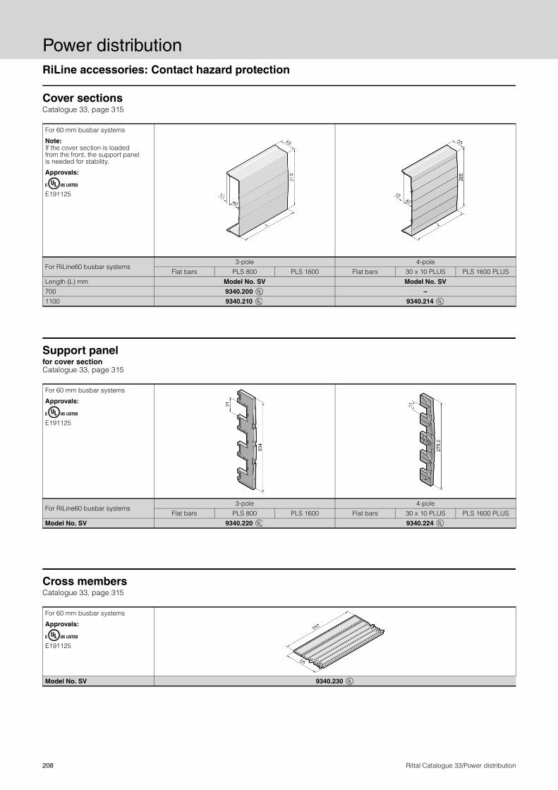
Power distributionRiLine accessories: Contact hazard protection
208 Rittal Catalogue 33/Power distribution
Cover sections Catalogue 33, page 315
For 60 mm busbar systems
Note: If the cover section is loaded from the front, the support panel is needed for stability.
Approvals:
E191125
For RiLine60 busbar systems 3-pole 4-pole
Flat bars PLS 800 PLS 1600 Flat bars 30 x 10 PLUS PLS 1600 PLUSLength (L) mm Model No. SV Model No. SV
700 9340.200 –
1100 9340.210 9340.214
Support panel for cover section Catalogue 33, page 315
For 60 mm busbar systems
Approvals:
E191125
For RiLine60 busbar systems 3-pole 4-pole
Flat bars PLS 800 PLS 1600 Flat bars 30 x 10 PLUS PLS 1600 PLUSModel No. SV 9340.220 9340.224
Cross members Catalogue 33, page 315
For 60 mm busbar systems
Approvals:
E191125
Model No. SV 9340.230

RiLine accessories: Connection system
Power distribution
209Rittal Catalogue 33/Power distribution
Conductor connection clamps Catalogue 33, page 316
Note: − Current carrying capacity
of connection cables, see page 150.
− Technical information onconductor connections, see page 149.
Approvals:
E191125
For bar thickness mm
Connection of round conductors1)
mm2
Clamping area for laminated copper bars W x H mm
Tightening torque
Nm
Width (B) mm
Height (H) mm Model No. SV
min. max.
3 – 5 1 – 4 – 2 8.0 – – 3550.000
5 1 – 4 – 2 11.0 17 23 3450.500
5 2.5 – 16 8 x 8 3 14.0 22 29 3451.500
5 16 – 50 10.5 x 11 8 18.5 26 39 3452.500
5 35 – 70 16.5 x 15 12 24.5 39 57 3453.500
5 70 – 185 22.5 x 20 15 30.5 44 66 3454.500
6 – 10 1 – 4 – 2 8.0 – – 3555.000
10 1 – 4 – 2 11.0 17 23 3455.500
10 2.5 – 16 8 x 8 3 14.0 22 29 3456.500
10 16 – 50 10.5 x 11 8 18.5 26 39 3457.500
10 35 – 70 16.5 x 15 12 24.5 39 57 3458.500
10 70 – 185 22.5 x 20 15 30.5 44 66 3459.5001) Wire end ferrules should be used with fine and extra-fine wire conductors.
22
B
B
H
Plate clamps Catalogue 33, page 316
For the electromechanical connection of laminated copper bars with E-Cu busbars.
For busbars mm
Clamping area for laminated copper bars W x H mm
Tighteningtorque
Nm
Clearance openingC
mmD
mm Model No. SVA mm
B mm
12 x 5 – 30 x 10 34 x 10 8 34 34 55 55 3554.000
40 x 10 34 x 10 8 44 34 65 55 3559.000
50 x 10 34 x 10 8 54 34 75 55 3560.000
50 x 10 54 x 10 8 54 54 75 75 3562.000
60 x 10 34 x 10 8 64 34 85 55 3561.000
60 x 10 54 x 10 8 64 54 85 75 3563.000
80 x 10 65 x 10 8 84 65 105 86 3460.500
C
D
A
B

Power distributionRiLine accessories: Connection system
210 Rittal Catalogue 33/Power distribution
System covers Catalogue 33, page 316
For 60 and 100 mm busbar systems (3-pole)
Approvals:
E191125
Width (B) mm
Depth (T) mm
Depth (T1)mm Model No. SV
50 80 40 3086.000
100 80 40 3087.000
100 110 70 3090.000
200 80 40 3088.000
200 110 70 3091.000
B
230
– 32
5
T
T1
Connection block Catalogue 33, page 317
Note: − When using the terminal
on 2-pole busbar systems(SV 9340.040, see page 205), the terminal must be rotated through 180° for connection to the PE busbar.
− Technical information on conductor connections, see page 149.
− Current carrying capacity of connection cables, see page 150.
Model No. SV 9342.311 9342.321
Assembly data for applications to IEC (EN)
Connection of round conductorsmm2 − Fine wire with wire end ferrule − Multi-wire
95 – 1851) 95 – 300
– –
Clamping area for laminated copper bars W x H mm − For 5 mm bar thickness − For 10 mm bar thickness
33 x 27 33 x 22
65 x 27 65 x 22
Tightening torque Nm 14 20 Material specifications
Contact track: E-Cu, silver-plated � �
Conductor connection clamp
Cast brass, nickel-plated � –
Stainless steel – � 1) Connection up to 240 mm2, fine-wire without wire end ferrule with a tightening torque of 20 Nm.

RiLine accessories: For RiLine60 component adaptors
Power distribution
211Rittal Catalogue 33/Power distribution
Support frame Catalogue 33, page 320
For OM adaptor and OM support
Width (B) mm 45 45 55 55Length (L) mm 170 237 170 237Model No. SV 9341.800 9341.820 9341.830 9341.850
Connection bracket Catalogue 33, page 322
For circuit-breaker component adaptor
Dimensions1) mm 6 x 9 x 0.8 10 x 15.5 x 0.8 10 x 32 x 1A mm – 26 19 23 19 26 29 28B mm – 65 66 71 67 51 57 62C mm – 43 36 40 36 62 46 38D mm – 9 10 9 7 9 12 14E mm – Ø 11 Ø 11 Ø 11 Ø 8 Ø 12 Ø 12 Ø 12Model No. SV 9342.570 9342.660 9342.670 9342.680 9342.690 9342.770 9342.780 9342.790
1) Number of membranes x membrane width x membrane thickness.

Power distributionRiLine accessories: For RiLine NH fuse elements
212 Rittal Catalogue 33/Power distribution
Busbar adaptor 100 mm for NH fuse-switch disconnectors sizes 1 to 3, for mounting plate assembly Catalogue 33, page 324
Note: For mounting NH fuse-switch disconnectors size 1 to 3 on busbar systems with 100 mm bar centre distance, an additional mounting hole (d = 5.5 mm) must be drilled in the respective discon-nector chassis as shown in the assembly instructions, stage 1 opposite. The busbar adaptor is then mounted on the busbar using M10 screws, see stages 2 and 3, and the disconnector is secured onto the adaptor as shown in stages 4 to 6.
For NH disconnectors Distance (A) mm Model No. SV
Size Model No. SV
19344.1109344.1309344.150
57 9344.810
29344.2109344.2309344.250
65 9344.820
39344.3109344.3309344.350
80 9344.830
100
100
AA
TX 25
17/19
2,5 Nm TX 25
ø 5,5
17 20 Nm19 30 Nm
1
2
3
4
4
5
6
Assembly instructions
Prism terminal for NH disconnectors size 00 with screw terminal Catalogue 33, page 323
ConnectionTightening torque
Nm Model No. SVRound conductor mm2
Sector-shaped conductor mm2
10 – 70 10 – 70 3 9344.600
Box terminals for NH disconnectors sizes 1 to 3 with screw terminal Catalogue 33, page 323
For NH disconnectors
Clamping area for laminated copper bars
W x H mm
ConnectionTightening torque
Nm Model No. SVRound conductor
mm2
Sector-shaped conductor
mm2 Size 1 20 x 14 35 – 150 50 – 150 12 9344.610
Size 2/3 32 x 20 95 – 300 120 – 300 20 9344.620
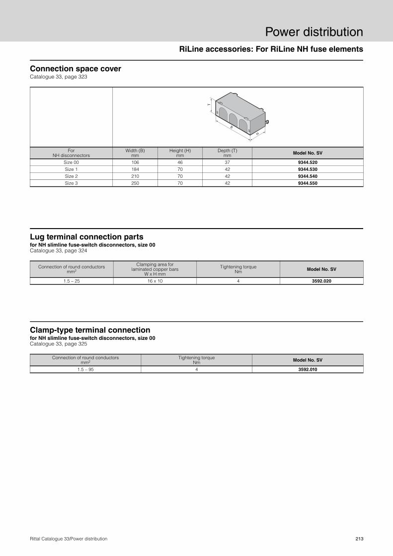
RiLine accessories: For RiLine NH fuse elements
Power distribution
213Rittal Catalogue 33/Power distribution
Connection space cover Catalogue 33, page 323
For NH disconnectors
Width (B) mm
Height (H) mm
Depth (T) mm Model No. SV
Size 00 106 46 37 9344.520
Size 1 184 70 42 9344.530
Size 2 210 70 42 9344.540
Size 3 250 70 42 9344.550
B
H
T
Lug terminal connection parts for NH slimline fuse-switch disconnectors, size 00 Catalogue 33, page 324
Connection of round conductors mm2
Clamping area for laminated copper bars
W x H mm
Tightening torque Nm Model No. SV
1.5 – 25 16 x 10 4 3592.020
Clamp-type terminal connection for NH slimline fuse-switch disconnectors, size 00 Catalogue 33, page 325
Connection of round conductors mm2
Tightening torque Nm Model No. SV
1.5 – 95 4 3592.010

Power distributionBusbar systems (100/185/150 mm)
214 Rittal Catalogue 33/Power distribution
Busbar supports (3-pole) Catalogue 33, page 340
Note: SV 3052.000The base component of the busbar support may also be used as a single-pole support.
Technical information for the calculation of rated currents to DIN 43 671, see page 152/153.
For bar systems 1250 A 1600 A 2500 A 3000 A Bar centre distance mm 100 185 150 150Max. bar accommodation without inserts mm 60 x 10 80 x 10 2 x 80 x 10 2 x 100 x 10
Inserts for – Reducing the
cross-section to mm– Reducing the bar width
in 10 mm increments
30 x 10 bis 50 x 10
–
50/60 x 10
–
–
�
–
�
Model No. SV 3073.000 3052.000 3055.000 3057.000
Assembly data for applications to IEC (EN)
Tightening torque Nm– Assembly screw– Lid attachment– Bar fastening screw
10 3 –
5 –
40
10 10 –
10 10 –
275
41
22
320
70
100
100
50
9
515
24
50.7
495
125
60
185
185
Ø 6.5
125
145
M12
30
420
105 160
30
150
150
375
9
30
105 170
40
42037
5 150
150
9
Connection plates for busbar supports SV 3055.000/SV 3057.000 Catalogue 33, page 341
Connection for For busbar supports T-head screw Tightening torque Nm Model No. SV
Ring terminal M10up to 240 mm2 SV 3055.000 M10 x 100 mm 15 3058.000
2 x ring terminals M10up to 240 mm2 SV 3055.000 M10 x 100 mm 15 3059.000
Laminated flat copper up to 40 x 10 mm SV 3055.000 M10 x 120 mm 15 3061.000
2 x ring terminals M101) up to 240 mm2 SV 3057.000 M10 x 120 mm 15 3061.000
1) Note: When using 100 x 10 mm busbars, one connection plate per teminal connection is omitted.
3 2 1
1
2
3
3

Maxi-PLS system components
Power distribution
215Rittal Catalogue 33/Power distribution
Maxi-PLS 1600/2000 Catalogue 33, page 328
51
2565
51
25
65
45.5
98.5
45
99.5
25
105
55
7555
50
8
99.5
45.5
37
36
22
51
38
59
Busbar support Model No. SV 9649.000
Busbar support, suitable for top mounting Model No. SV 9649.160
End supports Model No. SV 9649.010
Maxi-PLS 3200 Catalogue 33, page 328
51
8025
51
60.5
6080
148
25
146
70 50
70
130
100 50
8
Busbar support Model No. SV 9659.000
End supports Model No. SV 9659.010
Busbar support, suitable for top mounting Model No. SV 9659.160
Stabiliser Model No. SV 9650.140
148
60.5
42.5
5623
51
38
65.5
434 50
54.5
L3 L2 L1

Power distributionMaxi-PLS system components
216 Rittal Catalogue 33/Power distribution
Maxi-PLS 1600/2000/3200 Catalogue 33, page 329
Isolator chassis
64
DD
BA
C E
Model No. SV A B C D E9640.021 89 61 346 100 899650.021 89 61 479 150 949650.031 129 101 479 150 94
Model No. SV Size A
mmB
mmC
mmT-head screws
Tightening torque
9640.330 1 81 73 46 M10 20 Nm9640.340 2 112 104 77 M10 25 Nm9640.350 3 149 141 114 M10 30 Nm9650.330 1 81 73 46 M12 25 Nm9650.340 2 112 104 77 M12 30 Nm9650.350 3 149 141 114 M12 35 Nm
11.3
24.8
14.8
B
8.3
17.8
10.8
A
Sliding nuts (1600/2000)
Sliding nuts (3200)
405
A
B
C41
M10
40
9.5
A
M12
45
12.5
B
Connection plates Terminal studs (1600/2000)
Terminal studs (3200)
Model No. SV A B9640.370 M12 –9640.380 M16 –9650.370 – M129650.380 – M16
Model No. SV A B9640.900 M6 –9640.910 M8 –9640.920 M10 –9650.900 – M69650.905 – M89650.910 – M109650.920 – M12
Connection clampModel No. SV 9640.325SV 9650.325
1736
35
50.5
23

Maxi-PLS system components
Power distribution
217Rittal Catalogue 33/Power distribution
Divider panel Catalogue 33, page 331
Model No. SV
For enclosure height
mm
W (B1) mm
W (B2)mm
Model No. SV
For enclosure height
mm
W (B1) mm
9660.620 2000 502 418 9660.610 2000 502 9659.590 2000 702 618 9659.580 2000 702
1897
B2B1
138
1 2
B1
1897

Power distributionFlat-PLS system components
218 Rittal Catalogue 33/Power distribution
Flat-PLS 60/100Catalogue 33, see page 332
A B
Busbar support Flat-PLS
Busbar support Flat-PLS for stabiliser bar
SystemFor
busbars up to mm
A mm
B mm
C mm
D mm
E mm F Tightening
torque G
mm Model No.
SV
Flat-PLS 60 4 x 60 x 10 127.5 60 120 70 50 M8 8 Nm 100 9676.002
Flat-PLS 100 4 x 100 x 10 162.5 100 165 90 55 M10 9 Nm 125 9676.004
SystemFor
busbars up to mm
A mm
B mm
C mm
D mm
E mm F Tightening
torqueG
mm Model No.
SV
Flat-PLS 60 4 x 60 x 10 130 60 120 70 50 M8 10 Nm 100 9676.020
Flat-PLS 100 4 x 100 x 10 170 100 165 90 55 M10 12 Nm 125 9676.021
A
B
Model No. SV 9676.002SV 9676.004
Model No. SV 9676.020SV 9676.021

Flat-PLS system components
Power distribution
219Rittal Catalogue 33/Power distribution
Flat-PLS 60/100
B1
H1
H1
B1
B1 B1
H1
H1
B1
B1
H1
H1
B1
T1
H1
H2
10
B2
B1
T1
H2
H1
10 B1
A
A
H1
B2
8
H2
H3
B
B
H1
B2
8
H2
H3
B1
T1
T2
T1
B1
B3
B2
H2
10
H1
H3
H4
T1
B1
T2
T1
Busbar claws Catalogue 33, page 333
Edge cover section without spacer Catalogue 33, page 333
Contact makers Catalogue 33, page 334
Edge cover section with spacerCatalogue 33, page 333
Longitudinal connectors Catalogue 33, page 333
Side cover section Catalogue 33, page 333
Model No. SV W (B1) mm W (B2) mm H1 H2 D (T1) mm 9676.017 35.7 – 1) +2/–32) 309676.018 55.7 20 1) +2/–32) 309676.019 75.7 40 1) +2/–32) 30
1) Length of screw (to be ordered separately). 2) With reference to the required screw H2 = H1 – 20 (H1 length of screw).
2
1
1
Model No. SV W (B1) mm H1 mm 9676.041 10.2 12.99676.042 21.3 12.99676.043 32.3 12.9
1
2
3
H1
B1
B1 B1 B1
H1
B1 B1 B1 B1
H1
Model No. SV W (B1) mm W (B2) mm H1 mm H2 mm H3 mm D (T1) mm D (T2) mm 9676.526 60 36 40 – 100 20 10 30 –9676.546 60 36 40 – 100 20 10 70 409676.528 80 50 40 – 100 20 10 30 –9676.548 80 50 40 – 100 20 10 70 409676.520 100 50 40 – 100 20 10 30 –9676.540 100 50 40 – 100 20 10 70 40
2
1
2
1
2
1
Model No. SV W (B1) mm H1 mm 9676.052 10.3 16.69676.053 10.3 16.69676.054 10.3 16.6
1
2
3
A – A B – B
Model No. SV W (B1) mm
W (B2) mm
W (B3) mm
H1mm
H2 mm
H3 mm
H4 mm
D (T1) mm
D (T2)mm
9676.621 140 110 40 1) H1 – 40 20 10 30 –9676.641 140 110 40 1) H1 – 40 20 10 70 40
1) Length of screw (to be ordered separately).
2
1
Model No. SV W (B1) mm H1 mm9676.056 49.2 7.69676.058 69.2 7.69676.059 89.2 7.6
1
2
3
1
1 2 1 2
1
2
1 2 3
1 21
2
3
2 1
2
3
M = 20 Nm
M = 20 Nm
M = 20 Nm M = 20 Nm
M = 20 Nm

Power distributionFlat-PLS system components
220 Rittal Catalogue 33/Power distribution
Flat-PLS 60/100
B1
B2
H2
H1
Connection plates with bolts M12/M16Catalogue 33, page 335
Terminal block, distribution busbar Catalogue 33, page 358
Connection plates with bolts M10 Catalogue 33, page 335
Direct connection terminals Catalogue 33, page 335
1735
50.5
23
Model No. SV Size A
mm B
mm C
mm Tightening
torque9676.747 1 81 73 46 20 Nm9676.748 2 112 104 77 25 Nm9676.749 3 149 141 114 30 Nm
40
5
A
B
C
41
Connection plates for laminated copper bars Catalogue 33, page 335
Model No. SV W (B1) mm
W (B2) mm
W (B3) mm H1 H2
mm H3 mm
H4 mm
D (T1) mm
9676.700 70 40 M12 1) H1 – 21.5 30.6 15.6 609676.704 70 40 M16 1) H1 – 21.5 30.6 11.1 60
1) Length of screw (to be ordered separately).
Model No. SV W (B1) mm
W (B2) mm
W (B3) mm
W (B4) mm
W (B5) mm H1 H2
mm H3 mm
D (T1) mm
D (T2) mm
9676.710 50 – 30 M10 – 1) H1 – 40 5 35 35.79676.714 80 52 30 M10 82 1) H1 – 40 10 50 35.7
1) Length of screw (to be ordered separately).
1
2
Model No. SV
W (B1) mm
W (B2) mm H1 H2
mm D (T1)
mm D (T2)
mm 9676.730 35.7 35 1) H1 – 60 50.5 30
1) Length of screw (to be ordered separately).
Model No. SV W (B1) mm
W (B2) mm
W (B3) mm
W (B4) mm
W (B5) mm
H1mm
H2 mm
H3 mm
D (T1) mm
9674.485 160 130 61 51 29.5 40 20 25 209674.488 160 130 101 81 29.5 40 20 25 20
H2
H1
T2
T1
10
B1
B2
H1
H2
T1
10
B1
B2
H4
H3
B3
T2
T1
H1
H2
10
B4
B1
B3
H3
T1
H1
H2
T2
10
H3
B2
B3
B4
B1
B5
H3
T1
B3
B4
B5
4.5
10
1 2
M = 20 NmM = 20 Nm
M1 = 40 NmM = 20 Nm
M2 = 20 Nm
M = 20 Nm
M = 20 Nm Claw with threaded insert M10 Catalogue 33, page 335
Model No. SV
W (B) mm
D (T)mm
Tightening torque
9676.832 37.5 30 20 Nm
T B

System accessories for connection kits
Power distribution
221Rittal Catalogue 33/Power distribution
Stacking insulatorCatalogue 33, page 337
Model No. SV 9660.200
Ø 70
11
Ø 28
10.2
10.2
10.2
36
108
28
19

Power distributionCover systems: Form 1
222 Rittal Catalogue 33/Power distribution
Device modules Catalogue 33, see page 342
Enclosure width mm
Internal dimensions Mounting plate Model No. SV
W (B1) mm H1 mm D (T1) mm W (B2) mm H2 mm
600 432 263 245.5 420 2509660.700
9660.760
800 632 263 245.5 620 2509660.710
9660.770
2
3
3
2
1
H2H1
B1
T1
B2
Contact hazard protection cover Catalogue 33, page 342/343
Width B1 mm
Height mmModel No.
SVTop H1 Centre H2 Bottom H3 Trim panel H4
506 204 656 721 – 9660.280
506 246.5 567 567 20 9660.290
706 204 656 721 – 9660.380
706 246.5 567 567 20 9660.390
506 526 656 721 – 9660.780
506 567 567 567 – 9660.790
706 526 656 721 – 9660.880
706 567 567 567 – 9660.890
H1
H3
H4
H1
H2
H3
H1
H2
H3
B1
With device module single-door
With device module single-/3-door
With device module 3-door
Width B1 mm
Height H mm
Depth T mm
Width B2 mm1) Model No.
SVUse of longitudinal connectors none one side both sides
600 2000 600 500 450 400 9660.460
800 2000 600 700 650 600 9660.470
1000 2000 600 900 850 800 9660.480
1200 2000 600 1100 1050 1000 9660.490 1) Available installation width for Rittal NH slimline fuse-switch disconnectors.
H
B1
B2
T

Ri4Power: Compartment configuration
Power distribution
223Rittal Catalogue 33/Power distribution
Functional space divider Catalogue 33, page 349
With louvres
Model No. SV
Width of entry (B) mm
Depth of entry (T) mm
9673.436 212 2019673.438 212 2019673.456 412 2019673.458 412 2019673.476 612 2019673.478 612 201

Power distributionInstallation modules: ISV distribution enclosures
224 Rittal Catalogue 33/Power distribution
Mounting plate modulesCatalogue 33, page 362
86142 21
600
Clearance frame
Mounting plate module
Contact hazard protection
1
2
Support rail modules Catalogue 33, page 362
129
76
62
86
600
DIN rail mounted device modules Catalogue 33, page 363
8648.5
600

UPS systems
Power distribution
225Rittal Catalogue 33/Power distribution
UPS PMC 40/120/200/800 Catalogue 33, from page 373
Modular rack-mounting, energy-efficient, high-MTBF – these three attributes of Rittal UPS technology help to ensure low costs. Easily adapted to suit your specific requirements, its space requirements
are minimal, and maintenance work can be carried out quickly with the system operational. That's how efficient it is to ensure almost 100% availability.
Efficiency Particularly in the lower load range, a high efficiency really comes into its own, and also ensures significantly lower heat loss dissipa-tion.
25 50 75 100
97
96
95
94
93
92
91
90
94
95
95.5
96
Effi
cien
cy (%
)
Loading (%)
Category UPS classification to EN 620 40-3 Rittal UPS
1 VFI: UPS output independent of mains voltage and frequency variations within the limits to IEC 61 000-2-2 (Voltage and Frequency Independent)
PMC 800PMC 200PMC 120PMC 40PMC 12
2 VI: UPS output frequency dependent on mains frequency, voltage stabilised (electronic/passive) within the limits for normal operation (Voltage Independent)
3 VFD: UPS output dependent on mains voltage and frequency variations (Voltage and Frequency Dependent)
-0.80 -0.90
-0.90 1.00 0.80
1.00 0.90 0.80 0.70
100
75
50
25
0
Power factorO
utpu
t (%
)
Capacitive loadThe capacitive load is increasing in the IT environment. The UPS must be designed accordingly. The PMC 200 can emit constant and full active power from 0.9 kW capacitive to 0.8 kW inductive.
UPS PMC 12Catalogue 33, page 372
Parallel hot swap chassis: The parallel hot swap chassis for the 4.5 kVA and 6 kVA module allows up to 3 UPS systems to be connected together. This can be used to boost output and to achieve N+1 redundancy. An external bypass is additionally integrated into the Parallel Hot Swap Chassis.
PDM for PMC 12: Single-phase power distribution for use with the Parallel Hot Swap Chassis DK 7857.444. The PDM offers the opportunity of connecting two single-phase 32 A CEE connectors and four EN 60 320 C19 16 A connectors. All outputs have pre-fuses.
Increase output with parallel connection Block diagram parallel redundant UPS DK 7857.433/.434
Mains Load
Data cable for parallel switching

Power distributionUPS systems
226 Rittal Catalogue 33/Power distribution
UPS PMC 40Catalogue 33, page 373
PMC 40 – compact, rack-independent UPS system (up to 40 kW, 3-phase) This uses double conversion UPS technology according to the high-est classification VFI-SS-111, which provides a constant output irre-spective of the incoming voltage, coupled with a high overall effi-ciency and minimal space requirements.
The PMC 40 may be configured as a redundant system. As a gen-eral principle, it is important to ensure adequate climate control of the rack where the PMC 40 is installed. For installation purposes, the
rack must have two 482.6 mm (19˝) mounting levels and a minimum depth of 800 mm. Depending on the configuration, mixed popula-tion (e.g. with servers) in the same rack is also supported.The PMC 40 (redundant design) has “safe swap” capabilities. This allows easy, safe module exchange while the system is operational, without having to switch the UPS to bypass mode. Installation, com-missioning and maintenance must only be carried out by qualified personnel who have been authorised by Rittal.
UPS PMC 40 (type 1-4) Batteries of type 12 V/7 Ah
Basic unit Model No. Number of modules Battery Number of batteries PMC 40 type 11) 7040.010 11) 7040.211 40PMC 40 type 2 7040.020 1 7040.212 80PMC 40 type 31) 7040.030 21) 7040.212 80PMC 40 type 4 7040.040 2 7040.214 160
1) With 10 kW modules only
Overview of autonomy (Internal batteries of type 12 V/7 Ah)
Note:At half the UPS load, the autonomy (bridging time) is doubled in a linear pattern (in other words, for a capacity utilisation of 30%, 40%, 50%, the autonomies are double those shown in the table for 60%, 80%, 100%). At full load, PMC 40 20 kW modules always require two battery banks (2 x 40 x 7 Ah) and then achieve an autonomy of max. 5 min. Longer autonomies are only possible with UPSs PMC (type 5)/PMC 120 NX.
Common internal battery configuration of the UPS PMC 40 (type 1-4) Battery autonomy in minutes depending on module type and UPS load Module type 1 x 7040.110 (10 kW) 1 x 7040.120 (20 kW)
With 1 UPS module and the following battery configuration
Batteries per bank
Total number of batteries
Total system performance 8 kW (80%) 10 kW (100%) 12 kW (60%) 16 kW (80%) 20 kW (100%)
7040.211 40 40 8 6 5 1) 1) 7040.212 40 80 21 15 12 8 57040.214 40 160 47 35 28 18 5Module type 2 x 7040.110 (2 x 10 kW) 2 x 7040.120 (2 x 20 kW)
With 2 UPS modules and the following battery configuration
Batteries per bank
Total number of batteries
Total system performance 16 kW (80%) 20 kW (100%) 24 kW (60%) 32 kW (80%) 40 kW (100%)
7040.211 40 40 1) 1) 1) 1) 1) 7040.212 40 80 8 6 5 1) 1) 7040.214 40 160 20 15 11 8 5
1) Combination not possible.

UPS systems
Power distribution
227Rittal Catalogue 33/Power distribution
UPS PMC 40 (type 5)Catalogue 33, page 374
Overview of autonomy (Internal batteries of type 12 V/7 Ah)
Note:At half the UPS load, the autonomy (bridging time) is doubled in a linear pattern (in other words, for a capacity utilisation of 30%, 40%, 50%, the autonomies are double those shown in the table for 60%, 80%, 100%). At full load, PMC 40/PMC 120 20 kW modules always require battery banks of 50 (7040.315).
Common internal battery configuration of the UPS PMC 40 (type 5) Battery autonomy in minutes depending on UPS loadModule type 1 x 7040.110 (10 kW) 1 x 7040.120 (20 kW)
With 1 UPS module and the following battery configuration
Batteries per bank
Total number of batteries
Total system performance8 kW (80%) 10 kW (100%) 12 kW (60%) 16 kW (80%) 20 kW (100%)
2 x 7040.311 40 80 21 15 12 8 52 x 7040.315 50 100 28 21 16 11 83 x 7040.311 40 120 35 26 21 14 53 x 7040.315 50 150 47 35 28 19 144 x 7040.315 50 200 69 52 41 28 216 x 7040.311 40 240 88 66 52 35 5Module type 2 x 7040.110 (2x 10 kW) 2 x 7040.120 (2x 20 kW)
With 2 UPS modules and the following battery configuration
Batteries per bank
Total number of batteries
Total system performance16 kW (80%) 20 kW (100%) 24 kW (60%) 32 kW (80%) 40 kW (100%)
2 x 7040.311 40 80 8 6 5 – 1) – 1)
2 x 7040.315 50 100 11 8 7 4 – 1)
3 x 7040.311 40 120 14 11 8 6 53 x 7040.315 50 150 19 14 11 8 64 x 7040.315 50 200 28 21 16 11 86 x 7040.311 40 240 35 26 21 14 5Module type 3 x 7040.110 (3x 10 kW) 3x 7040.120 (3x 20 kW)
With 3 UPS modules and the following battery configuration
Batteries per bank
Total number of batteries
Total system performance24 kW (80%) 30 kW (100%) 36 kW (60%) 48 kW (80%) 60 kW (100%)
2 x 7040.315 50 100 7 5 4 – 1) – 1)
3 x 7040.311 40 120 8 6 5 – 1) – 1)
4 x 7040.311 40 150 12 9 7 5 44 x 7040.315 50 200 16 12 10 7 56 x 7040.311 40 240 21 15 12 8 5
1) Combination not possible.
Battery autonomy in minutes per UPS module
PMC 40 (type 5) module type (max. 3 modules) PMC 40/PMC 120 10 kW module
PMC 40/PMC 120 20 kW module2)
Separate internal battery per module8 kW 10 kW 12 kW 16 kW 20 kW
Model No. battery Battery bank per module (max. 3 modules)
7040.311 (1 x 40) x 7 Ah = 40 (120) 8 6 5 – 1) – 1)
7040.315 (1 x 50) x 7 Ah = 50 (150) 11 8 7 4 – 1)
2 x 7040.311 (2 x 40) x 7 Ah = 80 (240) 21 15 12 8 51) Combination not possible. 2) Module needs at least 50 blocks for full output or at least 2 x 40 blocks for 16 kW.

Power distributionUPS systems
228 Rittal Catalogue 33/Power distribution
UPS PMC 120 Catalogue 33, page 375
Overview of autonomy (External batteries of type 12 V/28 Ah) Common external battery configuration of the UPS PMC 120 Battery autonomy in minutes depending on UPS loadModule type 1 x 7040.110 (10 kW) 1 x 7040.120 (20 kW)With 1 UPS module and the following battery configuration Model No. battery rack
Battery Model No.
(x = quantity)
Batteries per bank
Total number of batteries
Total system performance
8 kW (80%) 10 kW (100%) 12 kW (60%) 16 kW (80%) 20 kW (100%)
7857.590 7857.374 x 4 40 40 54 41 32 22 57857.590 7857.374 x 8 40 80 134 101 79 55 57857.590 7857.374 x 12 40 120 227 170 134 93 57857.590 x 2 7857.374 x 16 40 160 329 247 195 134 57857.590 x 2 7857.374 x 20 40 200 425 319 253 175 57857.590 x 2 7857.374 x 24 40 240 536 403 319 221 57857.364/7040.361 7857.374 x 5 50 50 72 54 43 30 227857.364/7040.361 7857.374 x 10 50 100 179 134 106 73,5 547857.364/7040.361 7857.374 x 15 50 150 303 227 179 124 917857.364/7040.361 x 2 7857.374 x 20 50 200 439 329 260 179 1317857.364/7040.361 x 2 7857.374 x 25 50 250 565 425 336 233 1757857.364/7040.361 x 2 7857.374 x 30 50 300 713 536 425 294 221Module type 2 x 7040.110 (20 kW) 2 x 7040.120 (40 kW)With 2 UPS modules and the following battery configuration Model No. battery rack
Battery Model No.
(x = quantity)
Batteries per bank
Total number of batteries
Total system performance
16 kW (80%) 20 kW (100%) 24 kW (60%) 32 kW (80%) 40 kW (100%)
7857.590 7857.374 x 4 40 40 22 16 13 9 57857.590 7857.374 x 8 40 80 55 40 31 22 57857.590 7857.374 x 12 40 120 93 68 53 37 57857.590 x 2 7857.374 x 16 40 160 134 99 77 54 57857.590 x 2 7857.374 x 20 40 200 175 131 103 72 57857.590 x 2 7857.374 x 24 40 240 221 166 131 91 57857.364/7040.361 7857.374 x 5 50 50 30 22 17 12 97857.364/7040.361 7857.374 x 10 50 100 73 54 42 29 227857.364/7040.361 7857.374 x 15 50 150 124 91 71 49 377857.364/7040.361 x 2 7857.374 x 20 50 200 179 132 103 72 547857.364/7040.361 x 2 7857.374 x 25 50 250 233 175 138 96 727857.364/7040.361 x 2 7857.374 x 30 50 300 294 221 175 121 91Module type 3 x 7040.110 (30 kW) 3 x 7040.120 (60 kW)With 3 UPS modules and the following battery configuration Model No. battery rack
Battery Model No.
(x = quantity)
Batteries per bank
Total number of batteries
Total system performance
24 kW (80%) 30 kW (100%) 36 kW (60%) 48 kW (80%) 60 kW (100%)
7857.590 7857.374 x 4 40 40 13 9 7 5 – 1)
7857.590 7857.374 x 8 40 80 32 24 18 13 – 1)
7857.590 7857.374 x 12 40 120 54 41 32 22 – 1)
7857.590 x 2 7857.374 x 16 40 160 78 59 46 32 – 1)
7857.590 x 2 7857.374 x 20 40 200 104 78 61 43 – 1)
7857.590 x 2 7857.374 x 24 40 240 131 99 77 54 – 1)
7857.364/7040.361 7857.374 x 5 50 50 17 13 10 7 57857.364/7040.361 7857.374 x 10 50 100 43 32 25 17 137857.364/7040.361 7857.374 x 15 50 150 72 54 42 29 227857.364/7040.361 x 2 7857.374 x 20 50 200 105 78 61 42 327857.364/7040.361 x 2 7857.374 x 25 50 250 138 104 81 57 437857.364/7040.361 x 2 7857.374 x 30 50 300 175 131 103 72 54Module type 4 x 7040.110 (40 kW) 4 x 7040.120 (80 kW)With 4 UPS modules and the following battery configuration Model No. battery rack
Battery Model No.
(x = quantity)
Batteries per bank
Total number of batteries
Total system performance
32 kW (80%) 40 kW (100%) 48 kW (60%) 64 kW (80%) 80 kW (100%)
7857.590 7857.374 x 4 40 40 9 6 5 3 – 1)
7857.590 7857.374 x 8 40 80 22 16 13 9 – 1)
7857.590 7857.374 x 12 40 120 37 28 22 15 – 1)
7857.590 x 2 7857.374 x 16 40 160 54 41 31 22 – 1)
7857.590 x 2 7857.374 x 20 40 200 72 55 42 29 – 1)
7857.590 x 2 7857.374 x 24 40 240 91 68 53 37 – 1)
7857.364/7040.361 7857.374 x 5 50 50 12 9 7 4 – 1)
7857.364/7040.361 7857.374 x 10 50 100 29 22 17 12 97857.364/7040.361 7857.374 x 15 50 150 50 38 29 20 157857.364/7040.361 x 2 7857.374 x 20 50 200 72 55 42 29 227857.364/7040.361 x 2 7857.374 x 25 50 250 96 73 56 39 307857.364/7040.361 x 2 7857.374 x 30 50 300 121 91 71 49 37
1) Combination not possible.

UPS systems
Power distribution
229Rittal Catalogue 33/Power distribution
UPS PMC 120 Catalogue 33, page 375
Overview of autonomy (External batteries of type 12 V/28 Ah)
Note:At half the UPS load, the autonomy (bridging time) is doubled in a linear pattern (in other words, for a capacity utilisation of 30%, 40%, 50%, the autonomies are double those shown in the table for 60%, 80%, 100%). The autonomies shown are for guidance purposes only, and may deviate from the actual times due to differing battery conditions (such as ageing). Observe the battery ventilation/climate control requirements. At full load, PMC 40/PMC 120 20 kW modules always require battery banks of 50 (7040.315).
Common external battery configuration of the UPS PMC 120 Battery autonomy in minutes depending on UPS loadModule type 5 x 7040.110 (50 kW) 5 x 7040.120 (100 kW)With 5 UPS modules and the following battery configuration Model No. battery rack
Battery Model No.
(x = quantity)
Batteries per bank
Total number of batteries
Total system performance
40 kW (80%) 50 kW (100%) 60 kW (60%) 80 kW (80%) 100 kW (100%)
7857.590 7857.374 x 4 40 40 6 5 4 2 – 1)
7857.590 7857.374 x 8 40 80 16 13 9 6 – 1)
7857.590 7857.374 x 12 40 120 28 21 16 11 – 1)
7857.590 x 2 7857.374 x 16 40 160 41 31 24 16 – 1)
7857.590 x 2 7857.374 x 20 40 200 55 41 32 22 – 1)
7857.590 x 2 7857.374 x 24 40 240 68 51 40 28 – 1)
7857.364/7040.361 7857.374 x 5 50 50 9 6 5 3 – 1)
7857.364/7040.361 7857.374 x 10 50 100 22 16 13 9 77857.364/7040.361 7857.374 x 15 50 150 38 28 22 15 127857.364/7040.361 x 2 7857.374 x 20 50 200 55 41 32 22 177857.364/7040.361 x 2 7857.374 x 25 50 250 73 54 43 29 227857.364/7040.361 x 2 7857.374 x 30 50 300 91 68 54 37 28Module type 6 x 7040.110 (60 kW) 6 x 7040.120 (120 kW)With 6 UPS modules and the following battery configuration Model No. battery rack
Battery Model No.
(x = quantity)
Batteries per bank
Total number of batteries
Total system performance
48 kW (80%) 60 kW (100%) 72 kW (60%) 96 kW (80%) 120 kW (100%)
7857.590 7857.374 x 4 40 40 5 4 3 2 – 1)
7857.590 7857.374 x 8 40 80 13 10 7 5 – 1)
7857.590 7857.374 x 12 40 120 22 16 13 9 – 1)
7857.590 x 2 7857.374 x 16 40 160 32 24 19 13 – 1)
7857.590 x 2 7857.374 x 20 40 200 43 32 25 17 – 1)
7857.590 x 2 7857.374 x 24 40 240 54 41 32 22 – 1)
7857.364/7040.361 7857.374 x 5 50 50 7 5 4 3 – 1)
7857.364/7040.361 7857.374 x 10 50 100 17 13 10 7 57857.364/7040.361 7857.374 x 15 50 150 29 22 17 12 97857.364/7040.361 x 2 7857.374 x 20 50 200 43 32 25 17 137857.364/7040.361 x 2 7857.374 x 25 50 250 57 43 34 23 187857.364/7040.361 x 2 7857.374 x 30 50 300 72 54 43 29 22
1) Combination not possible.
Battery autonomy in minutes per UPS module
PMC 120 module type (max. 6 modules) PMC 40/PMC 120 10 kW module
PMC 40/PMC 120 20 kW module2)
Separate external battery per module8 kW 10 kW 12 kW 16 kW 20 kW
Model No. battery rack Batteries Battery bank per module (max. 3 modules)
7857.396 7857.374 x 4 (1 x 40) x 28 Ah = 40 54 41 32 22 – 1)
7857.396 7857.374 x 8 (2 x 40) x 28 Ah = 80 131 99 78 54 – 1)
7857.398/7040.362 7857.374 x 5 (1 x 50) x 28 Ah = 50 72 54 43 30 227857.398/7040.362 7857.374 x 10 (2 x 50) x 28 Ah = 100 175 131 104 72 54
1) Combination not possible. 2) Module needs at least 50 blocks for full output or at least 2 x 40 blocks for 16 kW.

Power distributionUPS systems
230 Rittal Catalogue 33/Power distribution
UPS, Power Modular Concept – PMC 200 Catalogue 33, page 376
N + 1 = Perfect redundancy in a rack with PMC 200
4040
1212121212
202020
Example 1 Example 2 Example 3
Example 1● 1 + 1 (40 kW + 40 kW)
Advantage: Just two UPS mo-dules, minimal space require-ments. Disadvantage: 100% of the required output must be provided as redundancy.
Example 2● 2 + 1 (2 x 20 kW + 20 kW)
Advantage: Compact and energy-efficient.
Example 3● 4 + 1 (4 x 12 kW + 12 kW),
an additional battery rack is needed for batteries. Advantage: Only 12 kW needs to be buffered for redundancy. Disadvantage: Greater space requirements.
Three examples of a 40 kW UPS with redundancy: All modules operate in parallel mode. In all cases, one module may fail without impairing the connected load.
Maximum energy efficiency with PMC 200
Redundancy
Power
Energy saving
Example 1 Example 2 Example 3
Minimal energy consumption means low costs and minimal pollution: With the PMC 200 concept, you not only protect the critical load, but also safeguard the operating ratio of the UPS. We will be happy to advise you on the most suitable concept.
Extremely small installation space with PMC 2000
3232
32
3232
120120
4040
4040
Example 1 Example 2 Example 3PMC 200
In examples 1 and 2 we com-pare the space requirements of two non-modular systems for 120 kW output plus redundancy with the modular UPS system
Rittal PMC 200 (example 3), which is configured according to the 4 + 1 concept with five 32 kW modules.
The minimised construction size of the Rittal PMC 200 concept allows three modules plus battery packs or five modules each with up to 40 kW in one Rittal 482.6 mm (19˝) TS 8 UPS enclosure.
Example 1 This 120 kW + 120 kW solution requires the most output for redundancy.
Example 2 This variant with three 40 kW modules only requires 1/3 of the output compared with example 1 for redundancy purposes.
Example 3 With five 32 kW modules only 1/4 is required for the buffer out-put of redundancy, compared with a single redundant 120 kW UPS. However, there is no space left in the rack for battery packs, i.e. an additional battery enclo-sure is needed.
We will be happy to work with you to project-plan the exact solution best-suited to your individual requirements.
�
Benefits thanks to minimal construction size and modular design.�
PMC 200 is an excellent solution with regard to energy and space requirements and also with a view to future expansion.
�
Maximum performance density in one free-standing enclosure!

UPS systems
Power distribution
231Rittal Catalogue 33/Power distribution
UPS, Power Modular Concept – PMC 200 Catalogue 33, page 376
Super-fast service with PMC 200
202020
20
Extremely short MTTR (Mean Time To Repair) If servicing is required, a 12 kW or 20 kW module may be
replaced with a 20 kW module, and a 32 kW or 40 kW module with a 40 kW module. This sim-plifies the logistics and ensures fast, flexible, cost-effective servicing.
Flexible scalability with PMC 200
202020
20
2020
20
Simple expansion while operational Output may be expanded from 2 to 3, 4 or 5 UPS modules via “hot swap” with the system
operational, without having to switch to bypass mode.
For four modules or more, an additional battery rack will be needed. The autonomy may also be flexibly modified to suit your requirements.
The Rittal PMC 200 modular system combines flexible adap-tation to customer-specific requirements with investment reliability and a high level of availability.

Power distributionUPS systems
232 Rittal Catalogue 33/Power distribution
UPS PMC 200Catalogue 33, page 376
Module range (per rack) Up to 100 kW Up to 200 kW
Module power kW 8 12 16 20 24 32 40
1. Rectifier data
Module types 10 15 20 25 30 40 50Power output per module kVA 10 15 20 25 30 40 45Power output per module kW 8 12 16 20 24 32 40Nominal input voltage V 3 x 380/220 V+N, 3 x 400/230 V+N, 3 x 415/240 V+N
Input voltage tolerance V3 x 306/177 V to 3 x 464/264 V for < 100% load 3 x 280/161 V to 3 x 464/264 V for < 80% load 3 x 160/138 V to 3 x 464/264 V for < 60% load
Input frequency Hz 35 – 70Power factor input PF = 0.99 � 100% loadStarting current A Limited by soft start/max. IN Distortion factor, THDI Sine-wave THDI = < 3% � 100% loadInput power with charged battery and rated output kW 8.5 12.8 17 21.3 25.5 33.9 42.9Input with battery charging and rated output kW 9.3 14 18.6 23.3 27.8 37.1 46.9
2. Battery specifications (maintenance-free lead and NiCd)
Module types 10 15 20 25 30 40 50No. of 12 V batteries No. 30 – 50 40 – 50 40 – 50 30 – 50 40 – 50Maximum charging current A 6 A standard 10 A standardBattery charging curve Ripple free; IU (DIN 41 773)Temperature-controlled battery charging Standard (temp. sensor optional)Battery test Automatic and periodic (adjustable)Battery type Maintenance-free lead and NiCd
3. Output data
Module types 10 15 20 25 30 40 50Power output per module kVA 10 15 20 25 30 40 45Power output per module kW 8 12 16 20 24 32 40Output current IN at cos phi 1.0 (400 V) A 11.6 17.4 23.2 29 35 46.5 58Output voltage V 3 x 380/220 V or 3 x 400/230 V or 3 x 415/240 VOutput voltage stability Static: < ± 1% dynamic (step load 0% – 100% or 100% – 0%): < ± 4% Output voltage distortion With linear load: < ± 2% with non-linear load (EN 62 040-3; 2001): < ± 4% Output frequency 50 Hz or 60 Hz
Output frequency tolerance Synchronous to input, network-led: < ± 2% or: < ± 4% Asynchronous quartz oscillator: ± 0.1%
Bypass mode Nominal input voltage at 3 x 400 V or 190 V – 264 V ph-N: ± 15% Admissible load unbalance (all 3 phases are controlled independently) % 100
Phase angle tolerance (with 100% unbalanced load) Deg. ± 0
Overload capacity in inverter mode 125% load: 10 min.150% load: 60 sec.
Short-circuit capacity A Inverter: 2 x IN during 250 msBypass: 10 x IN during 10 ms
Crest factor 3 : 1Efficiency AC – AC at 100%/75%/50%/25% load (cos phi 1.0) % 96/95/95/94 Eco-mode efficiency at 100% load % 98
4. Standards
Safety EN 62 040-1-1: 2003, EN 60 950-1: 2006EMC 2006, EN 61 000-3-2: 2000, EN 61 000-3-3: 2006, EN 61 000-6-2: 2006, EN 61 000-6-4: 2002 Classification code VFI-SS-111 EN 62 040-3: 2002Product conformity CEProtection category IP 20
5. General technical specifications
Noise level at 100%/50% load dB (A) 55/49 57/49 57/49 57/49 59/51 63/53 63/53Parallel configuration Up to 20 modulesAmbient temperature UPS / batteries (recommended) °C 0 – 40/20 – 25Siting Min. 20 cm spacing from the wall (required for cooling)Input and output wiring From the front, belowEfficiency AC – AC at 100%/75%/50%/25% load (cos phi 1.0) % 96/95/95/93.5Eco-mode efficiency at 100% load % 98

UPS systems
Power distribution
233Rittal Catalogue 33/Power distribution
UPS PMC 800Catalogue 33, page 377
1. PMC 800
Module type 64 80
Power output kVA 80 100Power output kW 64 80Nominal input voltage V 3 x 380/220 V+N, 3 x 400/230 V+N, 3 x 415/240 V+N
Input voltage tolerance(3 x 400 V)
Load < 100% (–23%, +15%)< 80% (–30%, +15%)< 60% (–40%, +15%)
Input frequency Hz 35 – 70Power factor, input 0.98Distortion factor, THDI 7 – 9% at 100% load
2. Battery specifications (maintenance-free lead and NiCd)
Maximum charging current per module A 16, ripple-free Battery performance curve IU (DIN 41 773)Number of batteries (12 V) 40 – 50
3. Output data
Module type 64 80
Power output per module kVA 80 100Power output per module kW 64 80Output voltage V 3 x 380/220 V, 3 x 400/230 V, 3 x 415/240 VOutput power factor 1Output voltage tolerance, static < ±1%Output voltage tolerance, dynamic < ±4%Distortion factor with non-linear load (EN 62 040-3: 2001) < ±3% Admissible load unbalance 100%Output voltage form SinusoidOutput frequency Hz 50 or 60 Overload capacity 125%: 10 min./150%: 1 min.
4. General technical specifications
Topology On-line, double conversion, VFI Parallel configuration For redundancy or output increase up to 10 modulesAmbient temperature °C 0 – 40 Cooling Fan-assistedVolume of cooling air required 1500 m3 at 25°C Siting Min. 20 cm distance from the wallCabling From the front, from belowOperating ratio cos phi = 0.8 Load: 100%, 75%, 50%, 25% % 95/95/93.5/92 Heat loss at 100% load cos phi = 0.8 W 3400 4200
Weight Active module 65 kg 65 kg
Passive module 70 kg 85 kgDimensions W x H x D mm 1400 x 1900 x 870
StandardsSafety EN 62 040-1-1: 2003, EN 60 950-1: 2001/A11: 2004, EN 50 091-2: 1995EMC EN 61 000-3-2: 2000, EN 61 000-3-3: 1995/A1: 2001, EN 61 000-6-4: 2001
Power EN 62 040-3: 2001
5. General technical specifications
Module range Up to 100 kW Up to 200 kWModule type 10 15 20 25 30 40 50
Noise level at 100%/50% load dB (A) 55/49 57/49 57/49 57/49 59/51 63/53 63/53Ambient temperature UPS °C 0 – 40Ambient temperature for batteries (recommended) °C 20 – 25
Storage temperature °C –25 to +70Battery storage time at ambient temperature Max. 6 monthsMax. height (above sea level) 1000 m (3300 ft)/without de-rating max. 3000 m (10000 ft) Relative humidity Max. 95% (non-condensing)
Accessibility Total accessibility from the front for servicing and maintenance(no access required from the side, roof or rear)
Siting Min. 20 cm spacing from the wall (required for cooling)Input and output wiring From the front, belowEfficiency AC – AC at 100%/75%/50%/25% load (cos phi 1.0) % 96/95/95/95
Eco-mode efficiency at 100% load % 98

Power distributionPower System Module PSM
234 Rittal Catalogue 33/Power distribution
PSM rail with measurementBusbar with integral output measurement Catalogue 33, page 384
Display and monitoring of the complete three-phase connection current and the power per rail. The display is local. In conjunction with CMC, the rail may be remotely administered and configured using standard protocols (SNMP, HTTP).
The following active functions are provided: ● Local display, legibility is independent from the
installation position. ● Measurement and monitoring of the current per
phase. Min./max. limits may be set. Measure-ment range 0 – 16 A.
● Measuring and monitoring of the voltage per phase. Min./max. limits may be set. Measure-ment range 0 – 250 V.
● Alarm notification via a flashing display. ● Remote administration of the PSM rail, editing
and monitoring of remote limits, SNMP trap message in case of alarm.
Simple connection via RJ connector
1 1
1
PSM rail with measurementSingle-phase, 32 A Catalogue 33, page 384
Busbar with integral output measurement to dis-play and monitor the entire connected current of the PSM bar. The display is local. The bar is remotely administrable and configurable in con-junction with the CMC system.
The following active functions are provided:● Local display● Measurement and monitoring of the current and
voltage. Adjustable limits. Measurement range 0 – 16 A/0 – 250 V
● Alarm notifications via a flashing display● Remote administration of the bar supported
(in conjunction with the CMC)
Supply includes:− Busbar with fixed connection cable,
with CE connector (32 A)− Instructions− Assembly parts
Power System Module PSM Busbar, current carrying capacity up to 96 A per rack Catalogue 33, page 384
The ever-expanding power requirements of mod-ern IT infrastructures demand refined solutions for power distribution inside the racks. This leads to an associated requirement for additional sockets. The new “intelligent power distribution system” from Rittal significantly reduces cabling and assembly work.
The modular system facilitates basic configura-tion of the racks, thanks to a vertical support rail with 3-phase infeed. The various insert modules to supply the active components may be snap-fitted into the support rail. This can even be done whilst the system is operational, because the support section is shock-hazard protected.
The various modules, earthing pins, IEC 320 etc. may be inserted into the support rail in any combi-nation. This is easily achieved, even by non-elec-tricians, thanks to the shock hazard protected plug & play system.
Technical specifications/benefits: ● 3-phase construction with a maximum current
of 3 x 16 A. ● A redundant three-phase infeed with 3 x 16 A
may also be added.● The redundant circuit is completely separate
from the 3 phases of the support rail.● Each plug-in module picks off a phase on the
support rail, either from infeed A or from the redundant infeed B, depending on the direc-tion of connection.
● Modules may be retrofitted whilst the system is operational.
● Plug-in modules may be equipped with integral overcurrent protection, so that only the affected module is deactivated in the event of an exces-sively high current. The other modules remain operational.
● Overvoltage protection may be integrated into the supply line.
The vertical support rail allows the slots to be used flexibly across the entire enclosure height, and configured in a redundant manner via sepa-rate power infeed to the individual modules.
Supply includes:− Busbar with connection socket− Assembly parts− Instructions Without cable.A
B
Reg No. A592

Power System Module PSM
Power distribution
235Rittal Catalogue 33/Power distribution
PSM busbarSingle- and 3-phase design with 32 A phase current Catalogue 33, page 384
Technical specifications: − Single- and three-phase design with a max.
current of 32 A per phase, 1 x 32 A or 3 x 32 A, 400/230 V, 50/60 Hz
− Accommodates up to 6 passive PSM modules− Integral circuit-breaker 16 A, Class C− Modules may be retrofitted whilst the system is
operational
Supply includes:− Busbar with CEE-conforming connector− Assembly parts− Instructions
PSM busbar With fixed infeed/RCD Catalogue 33, page 384
Busbar with Residual Current protective Device (RCD). The busbar is protected against inadmissi-bly high touch voltages by two RCDs with a rated differential current of 30 mA. One RCD protects 3 slots on the bar. Additionally, there are two 16 A miniature circuit-breakers integrated into the bar. Infeed is via a 32 A CE connector.
Supply includes:− Busbar with fixed connection cable (3 m)− Instructions− Assembly parts

Power distributionPower System Module PSM
236 Rittal Catalogue 33/Power distribution
Socket modules with switchable slotsCatalogue 33, page 385
The module has 8 current outlets with IEC320 C13 (depending on version C19/earthing-pin) slots. Each of the 8 slots is individually switchable (via the CMC system). Furthermore, a current indica-tor, circuit display and thermal overload protec-tion are integrated into the module. The module is twice the length of a standard PSM module, so that a maximum of 2 modules may be inserted into a 1200 mm long PSM rail, and a maximum of 3 modules into a 2000 mm long PSM rail.
Operate the module without CMC:For operation of the module, power pack DK 7201.210 and a connection cable are needed. Up to 2/3 modules may be operated in one PSM rail (1200/2000 mm) with one power pack.
Available functions: Current display, circuit dis-play and automatic selective activation
Operate the module with CMC:No additional power pack is needed; the module is supplied with power via the CMC system. Up to 4 x 4 modules may be connected to one Processing Unit II (DK 7320.100).
Available functions: Current display, circuit dis-play, automatic selective activation, via CMC in the network: Individual switching of the 8 current outlets, current limit monitoring, delayed switch-ing of the individual current outlets, status display of the module.
Recommended accessory list CMC: ● DK 7320.100 CMC Processing Unit II● DK 7320.425 CMC power pack 24 V,
input 100 – 230 V AC● DK 7320.440 CMC 1 U mounting unit● DK 7320.472 CMC connection cable sensor
unit 2 m● DK 7200.210 CMC connection cable D
230 V AC (depending on country version)● DK 7200.221 CMC programming cable
Description of functions: ● 2-digit local LED 7-segment current display on
the module. Legibility is independent from the installation position.
● Measuring and monitoring of the current per module. Min./max. limits may be set. Measurement range 0 – 16 A.
● Alarm messages are indicated via a flashing 7-segment display.
● Monitoring of the thermo-fuse.● Modules may be combined via the bus system,
to enable selective activation.● In conjunction with the CMC, the 8 individual
current outlets of the modules may be acti-vated and deactivated individually via HTTP and SNMP.
● Remote administration of the power supply, editing and monitoring of remote limits, SNMP trap messages in case of alarm.
● 8 IEC320 C13 sockets per module.● User administration.
Material:Aluminium section with plastic cover
Supply includes:− 1 module (max. 16 A per module)− 1 infeed cable 24 V DC or 1 bus cable− 1 adaptor for power pack 24 V DC
Also required:
A separate power pack (100 – 240 V AC/24 V DC) is required for stand-alone operation without CMC (DK 7201.210) and the relevant connection cables.
Design Model No. DK
8-way C13 7856.201
8-way C13, 482.6 mm (19˝) mounting 7200.001
2 x C13 and 4 x earthing-pin 7856.203
2 x C13 and 4 x C19 7856.204

Power System Module PSM
Power distribution
237Rittal Catalogue 33/Power distribution
PSM/PCU modulesIndividual current measurement per slot Catalogue 33, page 385
Features of the active PSM/PCU modulesin conjunction with the CMC● 2-digit local LED 7-segment current display
for total current values.● Individual current measurement per slot with
limit configuration via CMC web interface.● LED colour code for load assessment per
module/slot.● SNMP switching option via the network.● Up to 16 modules via a joint web interface
under one IP address. ● Monitoring of the current per module and
outgoing slot.● Limits may be freely configured.● The 8 individual slots of the module may be
switched separately in conjunction with the CMC. May also be linked to other CMC alarm messages.
● Alarm messages are additionally indicated by flashing LEDs.
PSM plug-in module/19˝ PCUModules for the Rittal PSM busbar system or for mounting on either the 482.6 mm (19˝) level or enclosure frame. In conjunction with Rittal CMC, the managed modules offer further convenient functions. These include event-controlled switch-ing of the outputs and current measurements for individual sockets. The switchable modules also feature sequential reconnection after a power failure. Versions are available for all the important connector types used in the data centre.
Note:− A PSM busbar (e.g. 7856.020) is required to
be able to use the PSM modules.Corresponding information can be found in Catalogue 33, from page 384.
− A CMC system is required for control and remote monitoring of the managed modules via TCP/IP. The CMC Processing Unit permits the administration of up to 16 modules. Corresponding information can be found in Catalogue 33, from page 768.
All relevant information is also to be found on the Internet at: www.rittal.com
Pho
to s
how
s a
conf
igur
atio
n ex
ampl
e w
ith e
quip
men
t not
incl
uded
in th
e sc
ope
of s
uppl
y.
Ingeniously simple: Optical load indicatorsAn immediate overview of phase loads at all times. No more worries about unnoticed over-loading or unbalanced power distribution in the rack.
Plug-in modules
Processing Unit II
TCP/IP