2, on the dynamic characteristics of balanced puma …koasas.kaist.ac.kr/bitstream/10203/1593/1/on...
TRANSCRIPT

222 IEEE TRANSACTIONS ON INDUSTRIAL ELECTRONICS, VOL. 35, NO. 2, MAY 1988
On the Dynamic Characteristics of a Balanced PUMA-760 Robot
Abstract-It has been generally accepted that the dynamic cbaracteris- tics of the articulated robot are very complex in nature represented by highly nonlinear and coupled second-order differential equations. The serial connectipn of several linkages can give the robot kinematic dexterity buf it also can be one of the reasons for increasing the complexity in the dynamic characteristics of the articulated robot. To reduce the&Fomplexities in robot dynamics, the authors have introduced a mechanical counter-balancing concept that is based upon the theory of adding balancing masses to unbalanced conventional manipulators. This paper examines the effects of balancing on the dynamic characteristics of the PUMA-760 robot when the designed counter-balancing mechanism is applied to the robot. Through theoretical and experimental study many distinct advantages such as simplicity in the dynamic equation and significant reduction in the total required input torques are demonstrated for various manipulator speeds and payload conditions. Based upon these results unique dynamic characteristics of the balanced PUMA-760 robot are discussed in detail.
I. INTRODUCTION VER SINCE the appearance of industrial robots in E manufacturing automation, more flexibility and higher
perforhance are required of industrial robots as products are becoming more diverse. This implies high accuracy and repeatability of the robot under high velocity and heavy payload and these have been considered as the ultimate goals of the performance of5obots. To meet these goals it is required that the robot dynapics should be fully understood and exploited in designing the robot controller. However, the dynamics of the articulated robot have been intractable because its dynamics can be represented by a set of complex nonlinear coupled second-order differential equations. These complex natures of the manipulator dynamics basically come from the complexity in the robot structural configuration to give kinematic dexterity of the robot by serial connection of several linkages. These complex dynamics of robots have been one of the major difficulties in designing the robot controller based upon full robot dynamics. Thus, most of the existing control schemes [1]-[6] were designed based upon the simplified robot model by neglecting the coupling effects between joints. Although they were designed based upon the simplified robot model, these proposed control algorithms such as adaptive schemes usually have a complicated form and
Manuscript received April 14, 1987; revised November 28, 1987. W. K. Chung is with the Department of Mechanical Engineering, Pohang
Institute of Science and Technology, Pohang, Korea. H. S. Cho is with the Department of Production Engineering, Korea
Advanced Institute of Science and Technology, Chongryangni, P.O. Box 150, Seoul, Korea.
IEEE Log Number 8820058.
are very hard to implement because of the rather long computational time required to generate the appropriate control inputs. The structure of the controller will became even more complex if the full robot dynamics are included.
In contrast to the above complicated software controller, some efforts have been made to reduce the complex nonlinear- ities in robot dynamics itself. These include simplification of the equations of motion [7] and mass redistribution to obtain time invariant inertia matrix as well as decoupled arm dynamics [8], [9]. Another design concept utilizing the arm- balancing mechanism includes the relief mechanism to mini- mize static loadings [ lo], the counter-balancing device for the four-bar linkage robot [ 1 11, the active gravity compensation method [12], the mass and spring balancing mechanism [13], and the time-optimal controller [ 141 for balanced manipula- tors. Chung et al. [15], [16] proposed a new concept of an automatic balancing mechanism (ABM) for the articulated robot that can actively balance each joint for the payload variation by moving the balancing masses. The simulation study showed that after application of the ABM: 1) the inertia matrix becomes time invariant for joints 2 and 3 , 2) computa- tional complexity in the robot dynamics can be reduced by about one half, and 3 ) the gravity loadings are eliminated, thus resulting in significantly reduced driving joint torques. Based upon the above simple dynamics, an optimal controller for the balanced robot was proposed in [ 171, which can produce good tracking performances.
The excellent theoretical results were investigated for the idealized 3-dof robot model. In the case of commercially available robots, however, their dynamics may be different from those of the idealized one. Therefore, the objectives of this paper are to investigate the effects of mechanical balancing on dynamic characteristics and required input torques by applying the balancing concept to the actual robot. The investigation was made in detail through both theoretical and experimental studies. The robot model used for these studies was the PUMA-760 robot, but only the first three links, i.e., the robot without wrist motion, were considered. The balancing mechanism was designed based upon the experimental data [18] and implemented to the PUMA robot. The investigations were performed over a wide range of manipulator speeds and payload conditions. Based upon the derived dynamic equatiuns the input joint torques of the balanced PUMA robot were computed theoretically and compared with the experimentally obtained ones. Also, quantitative analyses were performed to examine the distribu- tion of the dynamic terms of each joint.
0278-0046/88/0500-0222$01 .OO 0 1988 IEEE

CHUNG AND CHO: CHARACTERISTICS OF A PUMA-760 ROBOT 223
Balancing mass
Balancing mass
fixture
Fig. 1 . Schematic of the balanced PUMA-760 robot.
11. DYNAMIC FORMULATIONS: BALANCED AND UNBALANCED MANIPULATORS ( a ) Joint 2
As shown in Fig. 1, we consider three degrees of freedom of the PUMA-760 robot. In this schematic drawing, links 2 and 3 are shown to be equipped with a balancing mechanism. This mechanism is a mechanical balancing device that moves a counter-balancing weight to eliminate gravity loadings acting on joints 2 and 3, including the weight of payload. It is composed of two parts, balancing mass fixtures and movable balancing masses as shown in Fig. 2. The balancing mass fixtures were made of steel and designed to balance the robot with no payload when the movable balancing masses were located at their initial positions. The movable balancing masses, which weigh 10 kg, were made of Plumbum for link 3 due to the space limitation and made of steel for link 2. These were designed to cover the weight of payload up to 15 kg by sliding along the guide bar attached to the balancing mass fixture. When the manipulator picks up a payload, the balancing masses move from their initial position to an appropriate one to balance each link at their corresponding joints. Thus, depending upon the weight of payload, the position of each balancing mass at each joint varies. Total weights of the balancing mass fixtures were 98.3 kg for link 2 and 33.6 kg for link 3, which are heavy when compared to those of each linkage.
To investigate the effect of mechanical balancing on the (b) Joint 3
derive those of the balanced PUMA robot. In the following equations the superscript ‘ ‘b’ ’ indicates the variables associ-
as
ated with the robot with the balancing mechanism. d aK aK ap aD dt ab, ae, ae, ae, +-+-=T,-F,, ( l r i s 3 ) (1)
where K is the total kinetic energy, P is the total potential energy, D is the dissipation function, T, is the generalized torque, F , is the Coulomb friction torque associated with joint
A. Dynamic Equations of the Conventional PUMA Robot
The full dynamic equations of the PUMA robot model used in this study can be derived based upon the Lagrange equation

224 IEEE TRANSACTIONS ON INDUSTRIAL ELECTRONICS, VOL. 35, NO. 2 , MAY 1988
i, and Bi and 6, are the i" joint angle and angular velocity, respectively. Each term in ( 1 ) is expressed by
k = l A . r = l j = l k = l
(4)
where
aA b a d j
&=- ; 4 x 4 matrix, (izj)
aA; aejaek U, . Ilk-- - ; 4 x 4 matrix, ( i z k z j )
Ab=AAA:, a . . , A:- l , ( i = l , 2 , 3).
The derivation of these equations together with detailed definitions of the symbols can be found in [ 1 8 ] , [20]. In the above equations, Jai denotes the moment of inertia of the i" joint motor, mi is the mass of the ith link, g is the vector of gravity, Ab is the homogeneous transformation matrix, c i
denotes the distance from the i" coordinate frame to the mass center of link i, and Bi is the viscous friction coefficient of the i" joint. The pseudo-inertia matrix Ji in (2) is defined by
rJjll ~ i 1 2 ~ i 1 3 5114 1
The inertia related terms and the velocity related coefficients in the Coriolis and centrifugal torques can be computed from (7) and (8) for the three joints. These are expressed in matrix forms
D= [ D1l D22 Hi= [ Hi22 , D12 Dl3 Hi12 Hi13
symm. symm . Hi33
( i = l , 2 , 3) . (10)
For the PUMA-760 robot, we can assume that the mass centers of the second and third link lie on the X2 and Z3 axes, respectively, as shown in Fig. 1 . This assumption was found to be reasonable according to the experiment performed in [ 181. In this case the dynamic equations of the unbalanced manipula- tor for the first three links become
D l l ( e ) = J u l + J 1 1 1 +J133 +J233 + (5244+J344)(di+ O f c i )
+ (J211 + 2J214a2) ci + J333 s:3 + 2J334a2 c2&3
Dl2 ( e = { J214d2 + (J244 + 5344) a2d2 } s2 - J334d2 c 2 3
D13(e)= -5334d2C23
D 2 2 ( 8 ) = J u 2 + 5 2 1 1 +2J214a2+(J244+J344)ai
+ J333 + 2a2J334S3
0 2 3 ( e ) = J333 + J334a2s3
0 3 3 = Ju3 + J333
H I 12 ( e ) = - { 521 I + 2J214a2 + (5244 + 5344) a; } s2 C2
+ J 3 3 3 s 2 3 c 2 3 -5334a2(S2s23- c 2 c 2 3 )
Substituting (2)-(5) into (1) yields
3 3 3
Dik8k+ Hjkmekem+Juj8j+Bjej+Gj=T;-F,j k = 1 k = l m=l
(6)
where Djk are the acceleration-related inertia terms 3
Dik= Tr(U,kJjUi), i, k = l , 2, 3 (7) j = m a x (i ,k)
Hikm are the nonlinear Coriolis and centrifugal terms
Hjkm= Tr(ujkm4ui), i, k , m = l , 2, 3 ( 8 ) j = m a x (i ,k,m)
and Gi is the gravity loading torque 3
G i = C ( - r n i g T q i r j ) , i = l , 2 , 3. (9) j = ;
H113(e)=J333c23s23 +J33402C2C23
HI22 ( e ) = 5214 c2 d2 + (5244 + J344) a2 dZ c2 + J334d2 s23
H123(8)=5334d2s23
H133 (g) = HI23 ( e ) H 2 d g = -H112(9
H223 ( '1 = J334 a2 c3 H233 ( e ) = H223 ( e ) H3l1 ( e ) = - HI 13 ( e H322(!>= - f f 2 2 3 ( ! )
GI@) = O
G3 ( e ) = - gJ334s23
G2 ( e ) = - g { J214C2 + (5244 + J344)02C2 + 5334s23 }
(1 1 )
where S2 = sin d 2 , C2 = cos 02, S23 = sin ( 0 2 + 8 3 ) , c 2 3 = cos (0, + e,), and a2, d2 denote the length of the second link and the offset distance between the first and the second link, respectively. Each dynamic term has highly nonlinear and

CHUNG AND CHO: CHARACTERISTICS OF A PUMA-760 ROBOT 225
coupled dynamic characteristics although more complex wrist motions were omitted here. However, the dynamic character- istics of the robot become very simple when the balancing mechanism is applied as will be shown later.
the following equations hold for the given payload condition:
JiI4 + a2 (J;& + J,”,) = 0
J534 = 0. (14) B. Dynamic Equations of the Balanced Robot Model
When we apply the balancing mechanism to the given robot, the balancing procedure can be performed by two steps. In the first step we install the balancing mechanisms in links 2 and 3 to balance their own weight and in the second step, depending upon the weight of payload, the positions of balancing masses are determined to satisfy the following balancing conditions:
Xi= - { J 2 1 4 + ( m 2 + m 3 + m j + m 4
+ m5 + m6) az>/rn,l- a2
(12) 2; = - { 5 3 3 4 - 5 4 2 4 + (m4 + ms + m6) d 4 } / m ; .
Here, m i and mi represent the masses of balancing mecha- nisms of links 2 and 3, respectively, and 2,’ and bj’ denote, respectively, the locations of the mass centers of the second and third balancing mechanisms from their corresponding joint coordinate frame as shown in Fig. 1. The above balancing condition was expressed including the masses of wrist for the sake of completeness. The other components of mass centers were assumed to be zero. This assumption can be satisfied by designing the balancing mechanism whose masses are distributed symmetrically along the X2 and Z3 axes for joints 2 and 3, respectively. When the balancing mechanism is installed on each link, the dynamic parameters of links 2 and 3 are modified as
1 2
JR3 = Ji33 + - {Ig+ Zky- ZLZ} + m; (2; ) 2
ZL,xy Z i Y , and Zhz denote the inertial moments of inertia of the balancing mechanism with respect to the mass center of the mechanism.
The dynamic equations for the balanced PUMA-760 robot can be easily obtained by substituting (12) and (13) into (6) for joints 2 and 3. Using the balancing conditions (12) and (13),
Hizz = 0
Gf(e) = 0
Gi(!) = 0
G;(e) = 0.
Based upon these analyses the following observations can be made regarding the dynamics of both manipulators:
1) The inertia elements except D1 of the balanced robot are constant. They are independent of robot configurations while those of the balanced robot have configuration-dependent properties. In addition, coupling terms arise in the joint 1 dynamics of the unbalanced robot due to the link offset distance while these terms disappear in the corresponding joint of the unbalanced robot. This indicates that the balancing mechanism can simplify the robot dynamics significantly irrespective of the link offset distance.
2) The computational complexity reduces by about one half for all the joints after the application of ABM, and the Coriolis forces disappeared in the dynamics of joints 2 and 3.
3) The gravity loadings due to the link itself and payload are eliminated in the balanced PUMA robot. This feature greatly
226 IEEE TRANSACTIONS ON INDUSTRIAL ELECTRONICS, VOL. 35, NO. 2. MAY 1988
simplifies the dynamic characteristics of the conventional manipulators.
III. EXPERIMENTAL AND SIMULATION PROCEDURES
The objectives of simulations and experiments are focused on the investigation of the effects of balancing on the dynamic characteristics and the required input torques. These investiga- tions include 1) the variation of the required input torque with payload and working speed, 2) the quantitative analysis of each dynamic term contained in the dynamic equations of both robots for various payloads and working speeds, and 3) the evaluation of the payload capacity.
Since the dynamic characteristics of the robot depend upon the robot configuration, the work trajectory was chosen here to cover the whole work space as follows: All three joints were commanded to rotate simultaneously by VAL command. The motion range for each joint was given as: from - 30" to - 90" for joint 1, from - 80" to - 20" for joint 2, and from 110" to 170" for joint 3, which indicates descending motion of links 2 and 3. The velocity profile was determined from measured tachometer signals when all joints were driven with VAL speed 30.
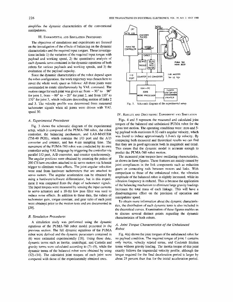
A . Experimental Procedures Fig. 3 shows the schematic diagram of the experimental
setup, which is composed of the PUMA-760 robot, the robot controller, the balancing mechanism, and LAB-MASTER (TM-40 PGH), which contains the I/O port and the A/D converter and counter, and has 4-ms sampling time. The movement of the PUMA-760 robot was conducted by its own controller using VAL language by triggering the controller via parallel I/O port, A/D converter, and counter synchronously. The angular positions were obtained by counting the pulses of 200 CT/turn encoders attached to dc servo motors via Schmitt trigger to eliminate noise effects. The joint angular velocities were read from hardware tachometers that are attached to servo motors. The angular acceleration can be obtained by using a hardware/software differentiator, but in this experi- ment it was computed from the slope of tachometer signals. The input torques were measured by sensing the input currents to servo actuators and a 10-Hz low pass filter was used to reduce noise effects. In addition to these data, the values of tachometer gain, torque constant, and gear ratio of each joint were obtained prior to the motion tests and are documented in 1201.
B. Simulation Procedures A simulation study was performed using the dynamic
equations of the PUMA-760 robot model presented in the previous section. The full dynamic equations of the PUMA robot were derived and the dynamic parameters contained in (6) were estimated experimentally [NI. Using these data, dynamic terms such as inertia, centrifugal, and Coriolis and gravity terms were calculated according to (7)-(9), while the dynamic terms of the balanced robot were obtained by using (12)-(14). The calculated joint torques of each joint were compared with those of the experimentally obtained ones.
PUMA 760 MAIN BODY
DISK DRIVER MICRO PROCESSOR
I I
Fig. 3 . Schematic diagram of the experimental setup
IV. RESULTS AND DISCUSSIONS: EXPERIMENT AND SIMULATION
Figs. 4 and 5 represent the measured and calculated joint torques of the balanced and unbalanced PUMA robot for the given test motion. The operating conditions were: zero and 5- kg payload with maximum 0.32-rad/s angular velocity, which was found to induce approximately 1.0-m/s tip velocity. By comparing both measured and theoretical results we can find that they are in good agreement both in magnitude and trend. This means that the dynamic model is accurate enough to predict the PUMA-760 robot motion.
The measured joint torques have oscillating characteristics, as shown in these figures. These features are mainly caused by joint compliances in the link components such as reduction gears or connecting rods between motors and links. With comparison to those of the unbalanced robot, the vibration amplitude of the balanced robot is slightly increased, while its vibration frequency is reduced. This is because the application of the balancing mechanism to eliminate large gravity loadings increases the total mass of each linkage. This will have a disadvantageous effect on the precision of operation and manipulator speed.
To obtain more information about the dynamic characteris- tics, the distribution of each dynamic term is also included in the theoretical curves. Examination of these figures enables us to discuss several distinct points regarding the dynamic characteristics of both robots.
A . Joint Torque Characteristics of the Unbalanced Robot
Fig. 4(a) shows the joint torques of the unbalanced robot for no payload condition. The required torque of joint 1 contains only inertia, velocity related terms, and Coulomb friction terms without gravity loading. The inertia torque of this joint exactly follows the trapezoidal velocity profile, although the torque required for the final deceleration period is larger by about 25 percent than that for the initial acceleration period.

CHUNG AND CHO: CHARACTERISTICS OF A PUMA-760 ROBOT 227
5
f -200.
0. g sl
0.
I- i *) -200..
sl -4m.
- r -400.- -
(a) Joint 1 I I I
(a) Joint 1
'ii 7
-400. - t ".,A -g -MO. sl -g O ' r
-m.- - .O 1.0 2.0 3.0 4.0 5.0 .O 1.0 2.0 3.0 4.0 5.0
T i m (sec) (C) Joint 3 T i m (sac)
(a)
.O 1.0 2.0 3.0 4.0 5.0 .O 1.0 2.0 3.0 4.0 5.0
Time (sec) (cl Joint 3 Time (sec1
(a)
,___. 0. - Total torque
+! f -200 . - 1- Total torque I
/ I -400. 1....11....1 (a) Joint 1
400. - Tota 1 torque
3 9 MO..
g U 0. 0 7
-4al.- (a1 Joint 1 - MO.r I I I
-= I I
'.. I -m. - - 2 M . u
(b) Joint 2 (bl Joint 2 m. I
-200.- - .O 1.0 2.0 3.0 4.0 5.0 .O 1.0 2.0 3.0 4.0 5.0
Time (sec) (C) Joint 3 Time (sec1
(b) Fig. 5. (a) Joint torques of the balanced PUMA robot. System parameters:
payload = 0 kg, V,,, = 0.32 rad/s. (b) Joint torques of the balanced PUMA robot. System parameters: payload = 5 kg, VmX = 0.32 rad/s.
.O 1.0 2.0 3.0 4.0 5.0 .O 1.0 2.0 3.0 4.0 5.0
Time (sec) (c) Joint 3 T i m (sec)
(b)
Fig. 4. (a) Joint torques of the unbalanced PUMA robot. System parame- ters: payload = 0 kg, V,,, = 0.32 rad/s. (b) Joint torques of the unbalanced PUMA robot. System parameters: payload = 5 kg, V,,, = 0.32 rad/s.
understood easily when we consider the configuration of the robot during the test motion. The gravity loading for joint 2 is much larger than that of joint 3, because link 3 itself as well as payload adds gravity burdens to joint 2, which is already under its own gravity loadings while link 3 feels gravity loadings of link 3 itself and the payload. The trends of the total joint torques required to drive joints 2 and 3 nearly follow those of the gravity loadings during the entire motion period.
Another point to be observed is that the total magnitudes of
This is caused by the fact that links 2 and 3 become distant from the vertical joint 1 axis as the robot moves to execute the given test motions. Therefore, the inertia torque has larger values during the final deceleration period. The torque characteristics of joints 2 and 3 are different from those of joint 1 because there always exists large gravity loading for all velocity conditions. The peak gravity loading is felt at near the final motion for joint 2 while joint 3 feels maximum gravity loading at the center of trajectory. This phenomenon can be
2 2 8 IEEE TRANSACTIONS ON INDUSTRIAL ELECTRONICS. VOL. 35, NO. 2, MAY 1988
the joint torques are found to be smaller than those of the gravity loading torques. The reason is that the test motion is a descending one, which means that the signs of Coulomb friction and gravity loading are opposite and thus cancel each other out. The situation is reversed if we move the manipulator upwardly, since in this case the joint torques will become much larger than the gravity torques as will be discussed in a later section. The significant effect of gravity loadings on joint torques even for zero payload condition implies that the PUMA-760 robot has highly unbalanced dynamic characteris- tics.
When we impose a 5-kg payload on the robot gripper it can be found in Fig. 4(b) that the torque characteristics of joint 1 are not affected by the payload. This feature is attributable to the fact that the inertia torque of joint 1 is mainly composed of large inertial moments of links 2 and 3 and that the Coulomb friction of this joint is dominant. However, for joints 2 and 3 the payload produces large gravity loadings and this loading exerts more severe effects on the input torques as shown in Fig. 4(b). The gravity loading is shown to be much larger than that induced for the no payload condition. The gravity loading is increased by about 60 N.m. for joint 2 and 35 N.m. for joint 3. From the above observations we can say that for the unbalanced robot operating with the above payload and velocity conditions the Coulomb friction plays an important role in the dynamics of joint 1, while the gravity loadings do in the joints 2 and 3 dynamics. This feature becomes more severe for heavier payload conditions. This has been one of the main reasons to complicate the dynamic characteristics of the manipulator, making it very difficult to implement an on-line dynamic control algorithm such as the computed torque method or adaptive control algorithms.
B. Joint Torque Characteristics of the Balanced Robot However, when we apply the balancing mechanism to the
balanced PUMA-760 robot as shown in Fig. 2, the dynamic characteristics of the unbalanced PUMA-760 robot become different from those of the unbalanced one as shown in Fig. 5. Fig. 5(a) shows the measured and calculated joint torques of the three joints when the balanced PUMA-760 robot has no payload. In this case the balancing mechanism compensates the gravity loadings of links 2 and 3 itself. The results for the case of the 5-kg payload are shown in Fig. 5(b). The joint torque characteristics of the balanced robot possess a distinct feature, compared with those of the unbalanced robot. That is, the joint torques during the constant speed period are nearly constant due to the absence of the gravity torque. These torques have positive or negative values depending upon the direction of each joint movement, which determines the sign of the Coulomb friction during the test motion. In these figures, the torques of joints 2 and 3 have positive value due to positive direction of these joints’ movements, while the torque of joint 1 has a negative value because the first joint moves in a negative direction. When we examine the results appearing in these figures, the following trends can be observed for the balanced PUMA robot:
1) During the constant velocity period where the gravity loading is dominant, the torques appear to be constant due to
the absence of gravity loading. To be more precise, these torques are not exactly constant due to the contribution of the centrifugal torque, but almost constant since the centrifugal torques are very small as compared with the Coulomb friction torques.
2 ) All joints appear to have similar trends in the required input torques, which are mainly composed of the Coulomb frictions together with rather small inertia torques.
3) The magnitudes of inertia torques ofjoints 2 and 3 for the accelerating period are the same as those for the decelerating period while those of the unbalanced robot have different values. This feature can be thought of as a result of time- invariant inertial properties for joints 2 and 3 as derived in (15).
C. Comparison of Both Manipulators’ Joint Torques In addition to the typical characteristics of the balanced
robot stated above, the joint torque magnitudes of the balanced robot can be compared more precisely with those of the unbalanced robot by analyzing the results of each joint.
For joint 1, when we examine the simulation results shown in Figs. 4(a) and 5(a), the inertia torque of this joint is found to be slightly increased during the deceleration period when compared with that of the unbalanced robot. This is due to the addition of heavy balancing masses to links 2 and 3. However, the peak values of the joint torques are almost the same for both manipulators since the increased inertia torque is very small. This trend is also observed even for the case of the 5-kg payload when we compare Figs. 4(b) and 5(b).
For joints 2 and 3, in the case of no payload condition the peak torques of joint 2 have no noticeable difference for both manipulators. But for joint 3, the peak joint torque of the balanced robot is slightly larger than that of the unbalanced robot. This is due to the fact that during the descending test motion the gravity loading of about 75 N.m. and the Coulomb friction of about 40 N.m. cancel each other out for the unbalanced robot, which is not the case for the balanced robot. Therefore, the unbalanced robot appears to have a smaller peak value than the balanced robot. For the case of a 5-kg payload as shown in Figs. 4(b) and 5(b), however, the peak joint torques of the balanced robot are found to be reduced by about 65 and 14 N.m. for joints 2 and 3, respectively, than those of the unbalanced robot due to the effects of the balancing mechanism. The reduction of the peak torques will be magnified for heavier payload conditions. For comparison purposes the peak joint torques during the ascending motion are also theoretically obtained for both manipulators. They are compared in Table I for two payload conditions. In this table, we can find that when the robot performs an ascending motion the required peak torque is about 403 and 200 N.m. for the unbalanced and balanced robot, respectively, even with no payload condition. This is a drastic reduction in peak value when compared with the result obtained for the descending robot motion in which both manipulators have no noticeable difference in peak value. This trend is also observed for joint 3; the peak torque of the unbalanced robot is about 117 N.m. while the balanced robot has about 59 N.m. peak torque. For the case of the 5-kg payload the peak values are summarized in

CHUNG AND CHO: CHARACTERISTICS OF A PUMA-760 ROBOT
I1 12 13
Ascending motion
229
141 N.m. 159 N.m. 403 N . m . 200 N.m. 117 N.m. 59 N.m.
TABLE I
AND BALANCED ROBOTS COMPARISON OF MAXIMUM JOINT TORQUES BETWEEN UNBALANCED
Joint Unbalanced Balanced
140 N.m. 145 N.m. 208 N.m. 200 N.m.
13 32 N.m. 59 N.m.
motion robot robot
Dcscendi ng motion
(a ) payload = 0 kg
motion
Descending motion
141 N.m. 147 N.m. 270 N.m. 205 N.m.
74 N . m . 61 N.m.
144 N.m. 162 N.m. 459 N.m. 150 N.m.
Ascending motion
( b ) payload = 5 kg
Table I(b). When the robot performs an ascending motion with this payload the balanced robot has very small peak joint torques for joints 2 and 3, which are less than half of the unbalanced robot.
To show more clearly how the magnitudes of each dynamic term are compared for both unbalanced and balanced manipu- lators, they are depicted in the histogram in Fig. 6 for the descending motion by summing the joint torques during the entire test motion. For joint 1, the balanced robot shows an increased value in inertia, centrifugal, and Coriolis, thus resulting in an increase in the total torque. But joints 2 and 3 reveal reduced magnitude in the total torque due to the absence of gravity loadings. This trend appears to be very much similar for the two payload conditions. Another important observation is that the balanced robot requires only a slight increase in total torque even with increased payload, while the unbalanced one requires total torque proportional to payload increase. These results strongly prove advantages of the balancing mechanism and will contribute to the development of future robots whose performance should be directed toward high accuracy together with fast speed and heavy payload.
V. CONCLUSIONS A mechanical balancing mechanism was applied to the
PUMA-760 robot. The distinct features of the balanced robot were analyzed and compared to those of the unbalanced robot through both theory and experiment.
The results obtained from the experimental and theoretical studies show that the conventional PUMA-760 robot has a highly unbalanced nature that depends highly upon the gravity loadings, which become more severe for a heavier payload condition. On the other hand, the dynamic characteristics of the balanced PUMA robot were shown to become very simple, revealing gravity-free and time-invariant inertial characteris- tics for joints 2 and 3 that are very close to the ideal robot model [ 191. The torque characteristics of the balanced robot
I C G T I C G T
(a) payload = 0 kg
(b) payload = 5 kg
(rad/s).
joints 1, 2, and 3 closely resemble each other in that these are mainly composed of the Coulomb frictions and inertia terms. The maximum torque of the robot, when the balanced robot performs a descending motion with no payload, is found to be slightly larger than that of the unbalanced one. With a 5-kg payload the significant reduction in the maximum joint torque was found to be magnified with a heavier payload. This trend was markedly noticeable with ascending robot motion for which the maximum torques of the balanced robot are less than half of those of the unbalanced robot. The implication of these results is that the balancing mechanism enables us to use a much smaller actuator system for heavier work conditions. From these observations we can conclude that the balancing mechanism can simplify complex dynamic characteristics and greatly reduce the required maximum torque while maintain- ing both kinematic dexterity and simple robot dynamics that have been antipathic to each other for serial robotic manipula- tors.
One thing to be mentioned is that additional mass of the balancing mechanism deteriorates vibration characteristics of the conventional robot. It appears to slightly increase the vibration amplitude and reduce the vibration frequency. This will have an unfavorable effect on the precision of operation and manipulator’s speed. A detailed study should be made to discuss the balancing mass effect on the vibration.
Fig. 6. Distribution of each dynamic terms. System parameters: V , = 1.0
REFERENCES [l] J. Y. S . Luh, M. W. Walker, and R. P. C . Paul, “Resolved-
acceleration control of mechanical manipulators,” ZEEE Trans. Automat. Contr., vol. AC-25, no. 3 , pp. 468-474, June 1980.
230 IEEE TRANSACTIONS ON INDUSTRIAL ELECTRONICS, VOL. 35, NO. 2, MAY 1988
I21
131
r41
151
161
r71
I81
[91
1101
I1 11
1121
S. Dubowsky and D. T. DesForges, “The application of model- referenced adaptive control to robotic manipulators,” Trans. ASME J. Dynamic Syst. Meas. Contr., vol. 101, pp. 193-200, Sept. 1979. C. S. G . Lee and M. J. Chung, “An adaptive control strategy for computer-based manipulators,” in Proc. IEEE Conf. Decision Control (Orlando, FL, pp. 95-100, Dec. 1982. D. P. Stoten, “Discrete adaptive control of a manipulator arm,” Optimal Control Applications Methods, vol. 3 , pp. 423-433, 1982. A. Hanafi, F. W. Wright, and J . R. Hewit, “Optimal trajectory control of robotic manipulators,” Mechanism and Machine Theory, vol. 19, no. 2, pp. 267-273, 1984. M. E. Kahn and B. Roth, “The near minimum-time control of open- loop articulated kinematic chains,” Trans. ASME J. Dyn. Sys. Meas. Contr., vol. 93, pp. 164-172, Sept. 1971. A. K. Bejczy and R. P. Paul, “Simplified robot arm dynamics and control,” IEEE Conf. Decision Control, pp. 261-262, 1981. H. Asada. “A geometrical representation of manipulator dynamics and its application to Arm design,” Trans. ASME J . of Dyn. Sys. Meas. Contr., vol. 105, pp. 131-135, 1983. H. Asada and K . Youcef-Toumi, “Analysis and design of a direct drive arm with a five-bar-link parallel drive mechanism,” Trans. ASME J . Dyn. Sys. Meas. Contr., vol. 106, pp. 225-230, Sept. 1984. A. Osyczka, J. Zajac, and J. Zamorski, “Optimum design of a relief mechanism of industrial robot,” in Proc. 15th ISIR (Tokyo, Japan), pp. 439-444, 1985. I . Imam and S. Levy, “Application of advanced computer-aided engineering tools for kinematic and dynamic analysis of robot sys- tems,” AUTOFACT4, pp. 3, 28-51, Dec. 1982. T. Arai, E. Nakano, T. Yano, R. Hashimoto, and I . Takeyama,
“Development of direct-drive human-like manipulator,” in Proc. 15th. ISIR (Tokyo, Japan), pp. 447-454, 1985. S. Mahalingam and A. M. Sharan, “The optimal balancing of the robotic manipulators,” in Proc. IEEE Conf. Robotics Automation (CA), pp. 828-835, Apr. 1986. W. S. Newman and N. Hogan, “The optimal control of balanced manipulators,” in Proc. ASME Winter Annu. Meeting (CA), pp. 177-184, Dec. 1986. W. K. Chung, H. S. Cho, C. W. Lee, and H. J. Warnecke, “Performance of robotic manipulators with an automatic balancing mechanism,” in Proc. ASME Winter Annu. Meeting (New Orleans),
W. K. Chung, H . S. Cho, M. J. Chung, and Y. K. Kang, “On the dynamic characteristics of balanced robotic manipulators,” in Proc. Japan4J.S.A. Symp. Flexible Automation (Osaka, Japan), pp. 119- 126, July 1986. W. K. Chung and H. S. Cho, “On the dynamics and control of the robotic manipulators with an automatic balancing mechanism,” in Proc. Institution MechanicalEngineers, vol. 201, no. B1, pp. 25-34, 1987. J. I. Moon, W. K. Chung, H. S. Cho, andD. G. Gweon, “Adynamic parameter identification method for the PUMA-760 robot,” in Proc. 16th ISIR (Briissels, Belgium), Oct. 1986. V. D. Tourassis and C. P. Neuman, “The inertial characteristics of dynamic robot models,’’ Mechanism and Machine Theory, vol. 20, no. I , pp. 41-52, 1985. J . I. Moon, “A study on dynamic parameter identification of PUMA- 760 robot,” M.S. thesis, Production Eng. Dept., KAIST, Korea, 1986.
pp. 111-121, 1984.