2, entanglement, and trapped-ion quantum … · chapter 10 electron g - 2, entanglement, and...
TRANSCRIPT

CHAPTER 10
Electron g - 2, Entanglement, and Trapped-Ion Quantum Information Processing
D. J. Wineland
nrne and Frequency Division, NIS2: Bouldel; CO 80305-3328
Abstract. Experiments on quantum-state synthesis of trapped ions and their connection to trapped- electron g - 2 experiments are discussed briefly. The trapped-ion work has the overall goal of performing large-scale quantum information processing; however, the techniques employed can also be applied to fundamental tests and demonstrations of quantum mechanical principles, as well as to the improvement of quantum-limited measurements.
INTRODUCTION
On this occasion where we honor Prof. Hans Dehmelt upon his retirement we can see, in many ways, his influence upon the work that we currently pursue. In research devoted to the possibility of processing quantum information using trapped ions, this influence is rather direct. For example, the trapped-ion method follows his pioneering work on its applications in atomic physics. In addition, the key entangling operation needed for quantum information processing is a close analog to the "g - 2" measurement technique that was used for the high-precision measurements of the electron and positron g-factors in Prof. Dehmelt's group at the University of Washington. Before discussing this connection, we first recall some of the basic ideas involved in the electron g - 2 measurement.
G - 2 AND SPINIMOTION ENTANGLEMENT
Consider an electron in a magnetic field go as shown schematically in Fig. 1. The energy of the electron's spin magnetic moment in this field is given by Hs = -@. -. Bo = -gj.lBBomS where g E -2.002 is the electron g-factor, p~ is the Bohr magneton, and ms E {- 112, +1/2) - {L, T) is the electron's spin eigenvalue with respect to a quantization axis determined by go. The electron's motion in a direction perpendicular to Bo is described by its cyclotron orbit (in the x-y plane of Fig. 1) at frequency

Trapped-ion quantum information processing 127
.FIGURE 1. Schematic representation of the motion of an electron in a strong uniform magnetic field plus a gradient field acting as a perturbation. When the electron traverses its cyclotron orbit, it sees an oscillating magnetic field parallel to 2 as it moves through the field gradient. If this field is modulated at Igl - 2 times the cyclotron frequency w, where g is the electron g-factor, the electron experiences an oscillating magnetic field that flips its spin.
= eBo/me where e and me are the electron's charge and mass. Assume that a weaker magnetic field gradient is also applied to the electron, where this additional field is perpendicular to Bo as indicated in the figure. As the electron traverses its cyclotron orbit, it sees an oscillating component of the magnetic field in the 2 direction due to its motion in the field gradient. Now assume that this field gradient oscillates sinusoidally at the frequency as - w , where as is the electron's spin-flip frequency. We represent the y-component of the electron's motion and the field gradient as
y (t) = Yo cos(wt) , dB, /dy = B' cos ((as - %It).
Lf we substitute these expressions into the expression for the total field (indicated in the figure), we find that the electron sees the field
The last term in this equation is non-resonant and may be neglected. However, the term that oscillates as cos(aSt) causes the spin to flip. Hence, by modulating the gradient field at a frequency equal to the "g - 2 frequency" as - = (Igl - 2) x Q, we cause the spin and cyclotron motion to exchange energy. After the cyclotron motion has radiatively re-thermalized with the environment, the change in averaged magnetic moment energy (spin plus cyclotron magnetic moment energy) is detected through a shift in the electron's axial frequency [I], thereby signaling the g - 2 resonance condition.

I
128 An Isolated Atomic Particle
If we describe this situation treating both the spin and motion mechanically, we write the system Hamiltonian as
where o+ = (ox + ioy)/2 and o- = (ox - ioy)/2 are the raising and lowering operators for the spin, and ox, oy, and o, are the usual Pauli matrices. Yo has been replaced
t by the position operator yo(ac + ac), where a c and a: are the lowering and raising operators for the cyclotron motion and yo represents the zero-point amplitude of the motion. When dBX/dy is modulated at the g - 2 frequency, the resonant (and dominant) part of HI is proportional to acof + aLo-, an interaction that entangles the spin and cyclotron motion. For pure states of two quantum systems, such as the spin and cyclotron motion in the present context, entanglement means that the wavefunction describing the overall system cannot be written as a direct product of wave functions of the separate systems. One consequence of entanglement is that measurements on one system are correlated with those on the other system. Logic gates used in quantum computers generate entanglement between quantum bits or "qubits" and, as we will see below, an interaction entirely analogous to that in Eq.(3) is the basis for entanglement and quantum logic gates between a t e s k i o n qubits.
BASIC IDEAS OF' TRAPPED-ION QUANTUM COMPUTATION
Efforts to realize the elements of quantum computation (QC) experimentally with trapped atomic ions have been stimulated in large part by a 1995 proposal by Cirac and Zoller [2]. In this scheme, ions confined in a linear RF (Paul) trap are cooled and form a stable spatial array whose motion is described by collective normal modes. Two internal levels in each ion form a qubit (referred to as a spin qubit below). The spacing (> 1 pm) between ions is typically large enough that the direct coupling of internal states of ions is negligible, thereby precluding logic gates based on internal-state interactions. To overcome this limitation, Cirac and Zoller suggested cooling the ions to their mo- tional ground state and using the ground and first excited state of a particular motional mode as a qubit (motion qubit). The motional mode can act as a data bus to transfer in- formation between ions by first mapping the spin qubit state of a particular ion onto the selected motion qubit with a laser beam focused onto that ion. The ability to construct a logic gate between the motion qubit and another selected spin qubit, coupled with the

Trapped-ion quantum information processing 129
ability to perform single-spin qubit rotations provides the necessary requirements for universal quantum computation [3,4].
The ion-trap scheme satisfies the main requirements for a quantum computer as out- lined'by DiVincenzo [5]: (1) a scalable system of well-defined qubits, (2) a method to reliably initialize the quantum system, (3) long coherence times, (4) existence of uni- versal gates, and (5) an efficient measurement scheme. Most of these requirements have been demonstrated experimentally; consequently, ion-trap quantum information proces- sors are studied in several laboratories. Here, we focus on experiments carried out at NIST but note that similar work is being pursued at Aarhus, Almaden (IBM), Hamburg, Hamilton (Ontario, McMaster Univ.), Innsbruck, Los Alamos (LANL), University of Michigan, Garching (MPI), Oxford, and Teddington (NPL, U.K.). For brevity, we dis- cuss only one example of a trapped-ion logic gate and indicate steps being taken towards scaling to a large system.
COHERENT QUANTUM CONTROL
The key entangling operation in the 1995 Cirac/Zoller scheme for QC, and other schemes that rely on the ions' motion, is an operation that coherently couples a spin qubit with the motion in a spin-state-dependent way. Assume that the spin qubit has a ground state labeled I L) and a higher metastable state labeled I f ) that are separated in energy by Am. First assume that single-photon transitions between these levels can be excited with a focused laser beam. For simplicity, we will assume electric dipole transi- tions, but this is easily adapted to other cases such as electric quadrupole transitions as in the experiments at Innsbruck [6]. The interaction between an ion and the electric field of the laser beam can be written as
where d i s the electric dipole operator, Z is the ion position operator for displacements from the ion's equilibrium position (expanded in terms of normal mode operators), kL
.is the laser beam polarization, k is the laser beam's k-vector (taken to be parallel to 2, the axis of the trap), CI)L is the laser frequency, and @ is the phase of the laser field at the mean position of the ion. Eo is the laser beam electric field amplitude at the ion, which is assumed to be classical. We characterize the laser field's polarization with respect to a magnetic field go that sets the quantization axis for the ions. The polarization is expressed in terms of left circular (&), linear (R), and right circular (&+) polarizations, so that kL = e-6- + eoR + e+&+ with le- l 2 + leoI2 + le+I2 = 1. The dipole operator .d is proportional to o+ + 0-, where o+ - I f ) (1 1, o ( 1) (f 1 . We take Z = zo(a +at), where a and at are the lowering and raising operators for the

130 An 1solated0~tornic Particle
harmonic oscillator associated with the selected motional mode (frequency mZ) and zo is the extension of the ground-state wavefunction for the particular ion (and mode) being addressed. We assume all other z modes are cooled to and remain in their ground states and for simplicity have neglected them in 2. In the Lamb-Dicke limit, where the extent of the ion's motion is much less than A1276 = Ilk, we can write Eq. (4) (in the interaction frame, and making the rotating wave approximation (see for example, ref. [lo])) as
Here, R -Eo(f 1 2 . 1) /(2h) and q = kzo is the Lamb-Dicke parameter (<< 1 in the Lamb-Dicke limit).
For certain choices of WL, HI is resonant and the spin and motion can be coupled efficiently. For example, when WL = - wZ, HI E iqh(Rei@)o+a + h.c. This is usually called the "red-sideband" coupling and is formally equivalent to the Jaynes-Cummings Hamiltonian from quantum optics (see, for example, Ref. '[7]). As noted above, it is essentially the same interaction used in the g - 2 experiments. Here, I J ) -+ I I') transitions are accompanied by In) -+ In - 1) motional mode transitions. When WL = Q + W, (the "blue sideband" frequency), HI 21 iqh(i2ei$) o+ai + h.c., and I 1) -t I T transitions .are J accompanied by In) -+ In + 1) transitions. When WL = q, HI -- h(S2ei )o+ + h.c. and I J) -+ I f ) transitions do not change n. These "carrier" transitions are used to perform the single spin-qubit rotations.
Raman transitions
Some experiments use two ground-state hyperfine levels as qubits. Coherent transi- tions between these levels can be implemented with two laser beams that drive coherent two-photon stimulated-Raman transitions. For this case, in Eq. (5) , k must be replaced by the difference Ak = lX1 - z21 between k-vectors for the two Raman beams (again as- sumed to be parallel to ?), WL and @ are replaced by ol - C& and - &, the frequency difference and phase difference between the laser beams at the mean position of the ion, and Rei@ is replaced by the resonant two-photon Raman Rabi rate
In this expression, the subscripts denote the two laser beams, li) are the (virtual, elec- tronically excited) intermediate states of the Raman process, and Ai are the detunings of the Raman beams as indicated in Fig. 2. We have assumed Ai >> yj:, where yj: are the decay rates from the intermediate states. With these substitutions, Eq. (5) applies in the
.. Trapped-ion quantum information processing 13 1
l i') 1 - - - - - - I ~ i ' 1
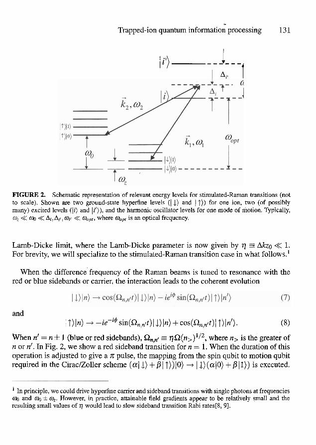
FIGURE 2. Schematic representation 'of relevant energy levels for stimulated-Raman transitions (not to scale). Shown are two ground-state hyperfine levels ( I J) and I T)) for one ion, two (of possibly many) excited levels (li) and lit)), and the harmonic oscillator levels for one mode of motion. Qpically,
<< @ << Ai,Ail, OF << Ooprr where o,~, is an optical frequency.
Lamb-Dicke limit, where the Lamb-Dicke parameter is now given by 77 = Mzo << 1. For brevity, we will specialize to the stimulated-Raman transition case in what follows.'
When the difference'frequency of the Raman beams is tuned to resonance with the red or blue sidebands or carrier, the interaction leads to the coherent evolution
and I T ) In) + -ie-jrn ~in(Q,,~lt) 1 1) In) + cos(Q, i t ) I T) In'). (8)
%%en n' = n 41 1 (blue or red sidebands), %,,I = q ~ ( n , ) ' / ~ , where n, is the of n or n'. In Fig. 2, we show a red sideband transition for n = 1. When the duration of this operation is adjusted to give a x pulse, the mapping from the spin qubit to motion qubit required in the Cirac/Zoller scheme ( a 1 1) + P I T ) ) 10) + I 1) (aJO) + P 11)) is executed.
In principle, we could drive hyperfine carrier and sideband transitions with single photons at frequencies oo and o& k y. However, in practice, attainable field gradients appear to be relatively small and the resulting small values of 77 would lead to slow sideband transition Rabi rates[& 91.

132 An Isolated Atomic Particle
From expressions (7) and (8) the entanglement between the spin and motion is evident since the final state cannot in general be factored into the product of spin and motional wavefunctions. Carrier transitions can also be described by these expressions, where n = n' and R,,,r = Q.
In order to keep the duration of an entangling operation relatively short, a,,,, for n # n' cannot be too small relative to fin,,. Therefore q must be chosen large enough that our interaction does not rigorously satisfy the Lamb-Dicke criterion and correction factors must be added to the expressions for the Rabi frequencies Q,,,I. These correction- factors, which can be called Debye-Waller factors [lo], have been observed by Meekhof et al. [ l 11 and also form the basis for a controlled-not (CNOT) gate between motion and spin discussed below.
State initialization and detection
To initialize the qubits for each experiment, we use a combination of internal-state optical pumping (to pump to the I L ) state) and sideband laser cooling to optically pump the motional modes to their ground states [6, 12, 13, 141. As in many atomic physics experiments, the observable in the ion-trap experiments is the ion's spin qubit state. We can efficiently distinguish ( 1) from I T) using a cycling transition to implement "electron- shelving" [15, 161 detection.
GATES
Equations (7) and (8) illustrate a basic source ofdentanglement in ion experiments from which universal logic gates have been constructed. For example, a CNOT and x-phase gate between the motion and spin qubit for a single ion have been demonstrated [lo, 171. Also, using the scheme suggested by Sgrensen and Mglmer [18, 191 and Solano et al. [20], a universal gate between.two spin qubits has been realized [21;22]. Here, another example of trapped-ion quantum gate is described.
Controlled-NOT " wave-packet" gate
Recently, a new kind of CNOT gate between the motion qubit (control bit) and spin qubit (target bit) that was proposed in Ref. [23] has been realized experimentally [24]. A CNOT gate toggles or leaves unaltered the state of the target bit depending on the state of the control bit. This gate described here uses carrier transitions and relies on

Trapped-ion quantum information processing 133
Debye-Waller correction factors [lo] to provide the conditional dynamics for the gate. Including these correction factors, the carrier Rabi frequencies now depend on n:
where L,,, (X) is the Laguerre polynomial of order n. For the lowest three values of n, we have
L , ( ~ ~ ) = 1, L~ ( ~ 2 ) = 1 - q2, L~ = 1 - 2 ~ 2 + q4/2. (10)
The spin (target) qubit was formed from the 2s 'sII2, 1 F = 2,mF = -2) = 1 1) and IF = 1, r n ~ = - 1) - I T) ground state hyperfine levels in ' ~ e + . For the motional (control) qubit states we chose the In = 0) and In = 2) Fock states of the axial ( z ) motion of the ion in a linear Paul trap [25]. Therefore the four basis states for the spin and motion qubit were 1 1) 10); 1 1) 12), 1 T ) lo), and I T) 12). TO construct the CNOT gate we chose q2 = 0.129, corresponding to q / 2 x = 3.51 MHz. This gave Q0,0/Q2,2 = 413. By choosing the interaction time such that Qo,ot = 2x, we realize the transformations 1 1) 10) -+ 1 1) lo), 1T)lO) + IT)lO), 11)12) + iJT)12), and 1T)12) + ilJ,)12). Up to phase factors that can be corrected by single-ion qubit rotations (or accounted for in software2), this gate is the CNOT gate. The gate operation is depicted schematically in Fig. 3.
This gate, when acting on eigenstates (as shown in the figure) acts like a classical gate. However it can also act on superposition states [24] (decidedly nonclassical), which leads to entanglement. Compared to the previously realized CNOT gate between motion and spin [17] this gate has the advantages that (1) it requires only one step instead of three, (2) it does not require an auxiliary internal state, and (3) it is immune to Stark shifts caused by coupling to "spectator" states [24] (here, two-photon Stark shifts from coupling to non-resonant sideband transitions). This gate is fundamentally different from previously demonstrated gates in that it relies on the wave-packet nature of the ions. To obtain the correct interaction with the laser, we must average the laser field over the extent of the ion's wave packet (giving the Debye-Waller factors) rather than assuming it is a point particle.
TOWAIPDS LARGE-SCALE QUANTUM COMPUTATION
Although simple logic operations among a few ion qubits have been demonstrated, a viable quantum computer must include a way to scale to very large numbers of qubits
The transformation looks like the desired CNOT operation followed by a n/2 phase shift (i = einI2 1 on the 12) state of the motion qubit. This phase shift can be removed by shifting the phase of the relevant laser oscillator for the next operation on the motion qubit.

134 An Isolated Atomic Particle
1.25 GHz
t3.4 MHz
FIGURE 3. Schematic of the trapped ion levels and CNOT gate operation. Shown here are the trapped ion motional levels (separated in energy by h x 3.4 MHz, where h is Planck's constant) and internal spin states I T ) and IJ). The motional states act as the control qubit and the internal states as the target qubit for the gate. The control qubit is composed of the ground and second excited motional states (n = 0,2) along the trap axis. The CNOT gate is operated by driving the carrier transition, which couples spin states with the same n. The laser-atom interaction is tuned so that an ion in the 10) state returns to its initial spin state while an ion in the (2) state toggles its spin state when the gate is driven. In the figure, filled circles represent two possible input ion eigenstates and open circles show the corresponding output state after the CNOT gate is applied.
and operations. As the number of ion qubits in a trap increases, several difficulties are encountered. For example, the addition of each ion adds three vibrational modes. It soon becomes nearly impossible to spectrally isolate the desired vibrational mode unless the speed of operations is slowed to an undesirable level [lo, 261. Furthermore, since error correction will most likely be incorporated into any large processor, it will be desirable to measure and reset ancillary qubits without disturbing the coherence of logical qubits. Since ion qubits are typically measured by means'of state-dependent laser scattering, the scattered light from ancillary qubits held in a common trap may disturb the coherence of the logical qubits.
For these and other reasons, it appears that a scalable ion-trap quantum computer system must incorporate arrays of interconnected traps, each holding a relatively small number of ions. The information carriers between traps might be photons [27, 28, 291, or ions that are moved between traps in the array. In the latter case, a "head" ion held in a movable trap could carry the information by moving from site-to-site as in the proposal of Ref. [30]. Similarly, as has been proposed at NIST, we could shuttle ions around in an array of interconnected traps [lo, 311. In this last scheme, the idea is to transfer ions between nodes in the array by applying time-dependent potentials to "control" electrode segments. To perform logic operations between selected ions, these ions are transferred into an "accumulator" trap. Before the gate operation is performed, it may be necessary to re-cool the ions without disturbing their internal states. This could be accomplished by sympathetically cooling the qubit ions with another ion species [lo]. Subsequently,

Trapped-ion quantum information processing 135
these ions are moved to memory locations or other accumulators. This strategy always maintains a relatively small number of motional modes that must be considered and minimizes the problems of ion~laser-beam addressing using focused laser beams. Such arrays also enable highly parallel processing and readout of ancillary qubits in separate trapping regions so that the logical ions are shielded from the scattered laser light. Some - initial steps towards this scheme have been reported in Ref. [32].
FUNDAMENTAL TESTS, QUANTUM MEASUREMENT APPLICATIONS
The ability to coherently manipulate entangled quantum states, at least on a small scale, has enabled some demonstrations and tests of quantum mechanical principles that would have otherwise remained as gedanken experiments. For trapped ions, nonclassical mo- tional states have been engineered by use of the basic elements of quantum computation [6, 111 and their properties determined through tomographic methods [33]. Schrodinger- cat states have been generated [34] and the scaling of their decoherence based on the size of the cat state has been verified [35,36]. A scheme for generation of arbitrary motional states has recently been demonstrated on a single ion [37]. Entanglement of two and four separate ions has been generated deterministically ("on demand") [21, 381 with- out the need for post-selection, as in experiments using parametric down-conversion of photons. This enabled the first experiment showing a violation of Bell's inequalities (on massive particles) while defeating the "detection loophole" [39]. Treated as a small quantum processor, the trapped ion system can simulate the dynamics of other systems such as nonlinear optical beam splitter's [40]. An exciting possibility is that these studies might eventually uncover some as-yet-unseen fundamental source of decoherence (see, for example, Ref. [41]).
One goal of the NIST experiments has been to use entanglement ("spin-squeezing") to increase the signal-to-noise ratio in spectroscopy and atomic clocks [8, 421. An experiment on two ions has recently shown such squeezing [43] and, although not yet of practical use, the squeezing that was obtained led to a signal-to-noise ratio higher than.
'could possibly be attained without entanglement on the same number of ions. Simple quantum processing might also be used to aid in quantum measurement readout with potential applications to mass spectroscopy [#I and frequency standards [45].

136 An Isolated Atomic Particle
,. . ACKNOWLEDGEMENTS ,(,.
The NIST work discussed in this paper resulted from the efforts of many colleagues. Recent work is beear; carried out in collaboration with NIST staff members Dietrich Leibfried and Wayne Itano, postdoctoral research associates Brian DeMarco, Volker Meyer, Mary Rowe, Murray Barrett, Tobias Schatz, and John Chiaverini; guest re- searchers Arnit Ben-Kish and Brana Jelenkovii; and University of Colorado graduate students Joe Britton, Chris Langer, Till Rosenband, and John Jost. The author thanks - Brian DeMarco and Tobias Schatz for helpful comments on the manuscript. This work was supported by the U. S. National Security Agency (NSA) and Advanced Research and Development Activity (ARDA) under Contract No. MOD-7171.00, and the U. S. Office of Naval Research (ONR). The article is a contribution of NIST, an agency of the U.S. government, and not subject to U.S. copyright.
REFERENCES
H. Dehmelt, Science 247,539 (1990). J. I. Cirac and P. Zoller, Phys. Rev. Lett. 74,4091 (1995). D. P. DiVincenzo, Phys. Rev. A 51,1015 (1995). A. Barenco et ad., Phys. Rev. A 52,3457 (1995). D. P. DiVincenzo, in Scalable Quantum Computers, edited by S. L. Braunstein and H. K. Lo (Wiley- VCH, Berlin, 2001), pp. 1-13. C. Roos et ad., Phys. Rev. Lett. 83,4713 (1999). J. M. Raimond, M. Brune, and S. Haroche, Rev. Mod. Phys. 73,565 (2001). D. J. Wineland et al., Phys. Rev. A 46, R6797 (1992). F. Mintert and C. Wunderlich, Phys. Rev. Lett. 87,257904 (2001). D. J. Wineland et al., J. Res. Nat. Inst. Stand. Tech. 103,259 (1998). D. M. Meekhof et al., Phys. Rev, Lett. 76,1796 (1996). F. Diedrich et al., Phys. Rev. Lett. 62,403 (1989). C. Monroe et al., Phys. Rev. Lett. 75, (1995). C. F. Roos et al., Phys. Rev. Lett. 85,5547 (2000). H. Dehmelt, Ann. Phys. Fr. 10,777 (1985). R. Blatt and P. Zoller, Eur. J. Phys. 9,250 (1988). C. Monroe et al., Phys. Rev. Lett. 75,4714 (1995). A. Sorensen and K. Molmer, Phys. Rev. Lett. 82, 1971 (1999). A. Sorensen and K. Molmer, Phys. Rev. A 62,02231 (2000). E. Solano, R. L. de Matos Filho, and N. Zagury, Phys. Rev. A 59,2539 (1999). C. A. Sackett et al., Nature 404, 256 (2000). D. Kielpinski et al., Science 291, 1013 (2001). C. Monroe et al., Phys. Rev. A 55, R2489 (1997). B. DeMarco et al., quant-phl0208180, Phys. Rev. Lett., to be published . C. Sackett, Quant. Inform. Comp. 1,57 (2001). A. M. Steane and D. M. Lucas, in Scalable Quantum Computers, edited by S. L. Braunstein, H. K. Lo, and P. Kok (Wiley-VCH, Berlin, 2000), pp. 69-88.

Trapped-ion quantum information processing 137
27. J. I. Cirac, P. Zoller, H. J. Kimble, and H. Mabuchi, Phys. Rev. Lett. 78,3221 (1997). 28. T. Pellizzari, Phys. Rev. Lett. 79, 5242 (1997). 29. R. G. DeVoe, Phys. Rev. A 58,910 (1998). 30. J. I. Cirac and P. Zoller, Nature 404, 579 (2000). 31. D. Kielpinski, C. Monroe, and D. J. Wineland, Nature 417,709 (2002). 32. M. A. Rowe et al., Quant. Inform. Comp. 2,257 (2002). 33. D. Leibfried et al., Phys. Rev. Lett. 77,4281 (1996). 34. C. Monroe, D. M. Meekhof, B. E. King, and D. J. Wineland, Science 272, 1131 (1996). 35. C. J. Myatt et al., Nature 403, 269 (2000). 36. Q. A. Turchette et al., Phys. Rev. A 62,053807 (2000). I
37. A. Ben-Kish et al., quant-ph/0208181, Phys. Rev. Lett., to be published . 38. Q. A. Turchette et al., Phys. Rev. Lett. 81, 1525 (1998). 39. M. A. Rowe et al., Nature 409,791 (2001). 40. D. Leibfried et al., Phys. Rev. Lett. 89, 247901 (2002). 41. A. J. Leggett, Physics World 12,73 (1999). 42. J. J. Bollinger, W. M. Itano, D. J. Wineland, and D. J. Heinzen, Phys. Rev. A 54, R4649 (1996). 43. V. Meyer et al., Phys. Rev. Lett. 86,5870 (2001). 44. D. J. Heinzen and D. J. Wineland, Phys. Rev. A 42,2977 (1990). 45. D. J. Wineland et al., in Proc. 6th Symposium Frequency Standards and Metrology, edited by P. Gill
(World Scientific, Singapore, 2002), pp. 361-368. /