2. elastic beam analysis with generic section - · pdf fileelastic beam analysis with generic...
TRANSCRIPT
2-1 CivilFEM Workbook. Ingeciber, S.A.©
Ver. 14.5
2. Elastic Beam Analysis with Generic Section
Applicable CivilFEM Product: All CivilFEM Products
Level of Difficulty: Easy
Interactive Time Required: 30-35 minutes
Discipline: Structural Steel
Analysis Type: Linear static
Element Type Used: BEAM4
Active Code: Eurocode 3
Units System: lbf, ft, s
CivilFEM Features Demonstrated: Units selection, code selection, material definition, generic section definition, postprocessing of stresses
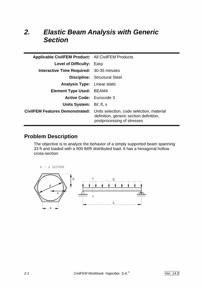
Problem Description
The objective is to analyze the behavior of a simply supported beam spanning 33 ft and loaded with a 900 lbf/ft distributed load. It has a hexagonal hollow cross-section.
L
q
a
d a
b
2-2 CivilFEM Workbook. Ingeciber, S.A.©
Ver. 14.5
Given
The geometry and load distribution of the simply supported beam are shown in the previous figure. The following is a list of all the input parameters:
Material Generic material
Young modulus 4.2E9 lbf/ft2
Length L = 33 ft
Distributed load q = 900 lbf/ft
Section geometric parameters
a = 2 ft
b = a · 3 / 2 ft
d = 3 ft
Approach and Assumptions
We are going to discretize the beam with a 3D model, using linear beam elements. Model geometry is defined with solid modeling and automatic meshing of elements and nodes.
2-3 CivilFEM Workbook. Ingeciber, S.A.©
Ver. 14.5
Summary of Steps
Preprocessing
1. Specify title
2. Set code and units
3. Define material
4. Define element type
5. Capture section
6. Define Beam & Shell properties
7. Define solid modeling entities
8. 8. Mesh
9. Save the database
Solution
10. Apply displacement constraints
11. 11. Apply pressure load
12. Solve
Postprocessing
13. Enter the postprocessor and read results
14. Plot the deformed shape
15. Plot bending stress in Z top fiber
16. List bending stress in Z top fiber
17. Exit the ANSYS program

2-4 CivilFEM Workbook. Ingeciber, S.A.©
Ver. 14.5
Interactive Step-by-Step Solution
Preprocessing
A typical CivilFEM analysis begins with providing data such as the units system, active code, materials, element types, model and section geometry definition
1. Specify title
Although this step is not required for a CivilFEM analysis, we recommend that you make it part of all your analyses.
Utility Menu: File Change title
Enter the title: “Elastic beam analysis with generic section”
OK to define the title and close the dialog box.
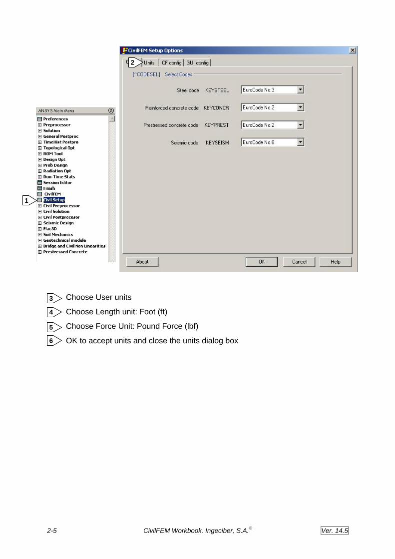
2. Set code and units
In CivilFEM you can choose between different codes for checking and designing. CivilFEM allows you to uphold different active codes simultaneously, one for concrete calculations another one for steel calculations and a third one for seismic design. In this example the active steel code is Eurocode No 3, it’s the default code for steel so we don’t need to change anything.
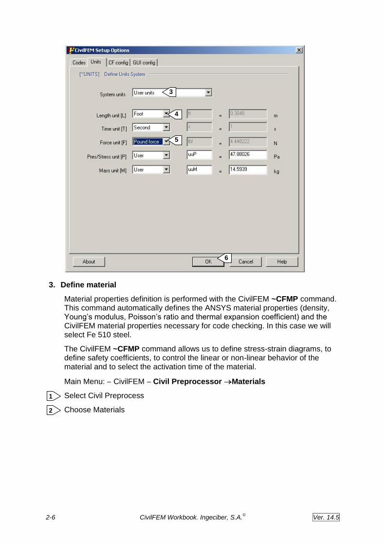
In CivilFEM you must also define a unit system. CivilFEM will need such a system to perform calculations according to Code. You should maintain it during the entire design. In this analysis, we will select American units, that is, feet, seconds and pounds-force.
Main Menu: CivilFEM Civil Setup
Select CivilFEM Setup
Choose Units
1
2
1
2
1
2
2-5 CivilFEM Workbook. Ingeciber, S.A.©
Ver. 14.5
Choose User units
Choose Length unit: Foot (ft)
Choose Force Unit: Pound Force (lbf)
OK to accept units and close the units dialog box
6
5
4
3
2
1
2-6 CivilFEM Workbook. Ingeciber, S.A.©
Ver. 14.5
3. Define material
Material properties definition is performed with the CivilFEM ~CFMP command. This command automatically defines the ANSYS material properties (density, Young’s modulus, Poisson’s ratio and thermal expansion coefficient) and the CivilFEM material properties necessary for code checking. In this case we will select Fe 510 steel.
The CivilFEM ~CFMP command allows us to define stress-strain diagrams, to define safety coefficients, to control the linear or non-linear behavior of the material and to select the activation time of the material.
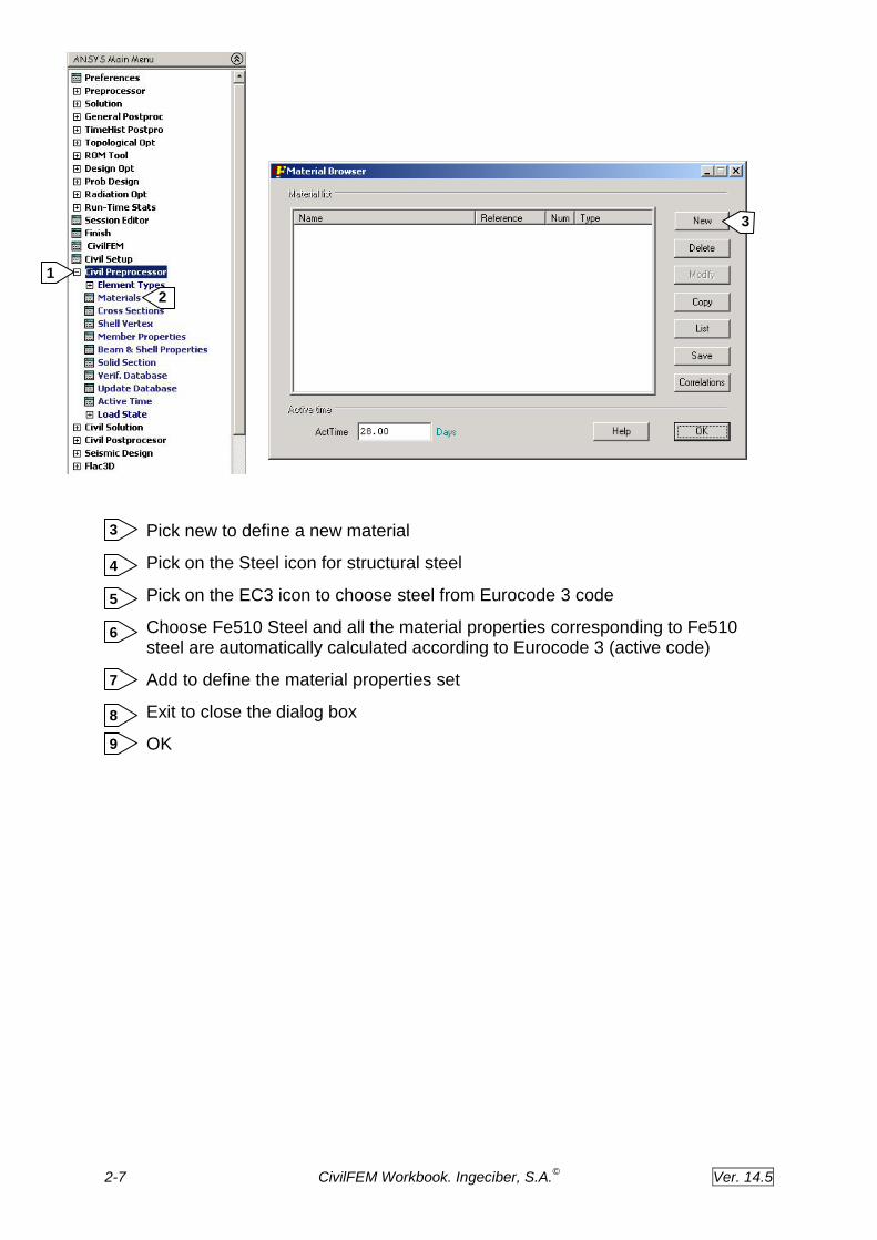
Main Menu: CivilFEM Civil Preprocessor Materials
Select Civil Preprocess
Choose Materials
2
1
3
4
5
6
2-7 CivilFEM Workbook. Ingeciber, S.A.©
Ver. 14.5
Pick new to define a new material
Pick on the Steel icon for structural steel
Pick on the EC3 icon to choose steel from Eurocode 3 code
Choose Fe510 Steel and all the material properties corresponding to Fe510 steel are automatically calculated according to Eurocode 3 (active code)
Add to define the material properties set
Exit to close the dialog box
OK
3
7
4
5
6
8
9
1
2
1
2
3

2-8 CivilFEM Workbook. Ingeciber, S.A.©
Ver. 14.5
4
9
5
6
7 8

2-9 CivilFEM Workbook. Ingeciber, S.A.©
Ver. 14.5
4. Define element type
Checking and designing according to codes is performed only on CivilFEM supported element types. Although you can use any ANSYS element to define your model, only the CivilFEM supported elements will be checked according to codes. In the element type menu you can see the CivilFEM supported beam elements.
We will use a 3D elastic Beam 4 for this analysis.
Main Menu: CivilFEM Civil Preprocess Element Types Civil Beams
Select 3D Elastic Beam 4
OK to define element type
5. Capture section
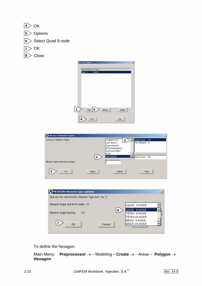
CivilFEM allows the use of ANSYS element MESH200 for automatic section definition, calculating its mechanical properties and defining its real constants. First we define the element type MESH 200 with the 8 node quadrilateral option.
Main Menu: CivilFEM Civil Preprocess Element Types Other
Elements Add/Edit/Delete
Choose Add to add a new element type
Select Not Solved
Select Mesh Facet 200
1
2
1
2
3
2
1
2-10 CivilFEM Workbook. Ingeciber, S.A.©
Ver. 14.5
OK
Options
Select Quad 8 node
OK
Close
To define the hexagon:
Main Menu: Preprocessor Modeling Create Areas Polygon Hexagon
1
4
5
6
7
8
5
8
3
2
4
6
7

2-11 CivilFEM Workbook. Ingeciber, S.A.©
Ver. 14.5
Enter 0 for Working Plane X coordinates
Enter 0 for Working Plane Y coordinates
Enter 2 for radius of the hexagon
OK to define hexagon
To define the central circle:
Main Menu: Preprocessor Modeling Create Lines Arcs By Cent & Radius
Enter 0
Apply
Enter 1.5
OK
1
2
3
4
4
7
8
6
5

2-12 CivilFEM Workbook. Ingeciber, S.A.©
Ver. 14.5
Enter 6 lines in arc
Ok to define circle
9
10
10
9
8 6
2-13 CivilFEM Workbook. Ingeciber, S.A.©
Ver. 14.5
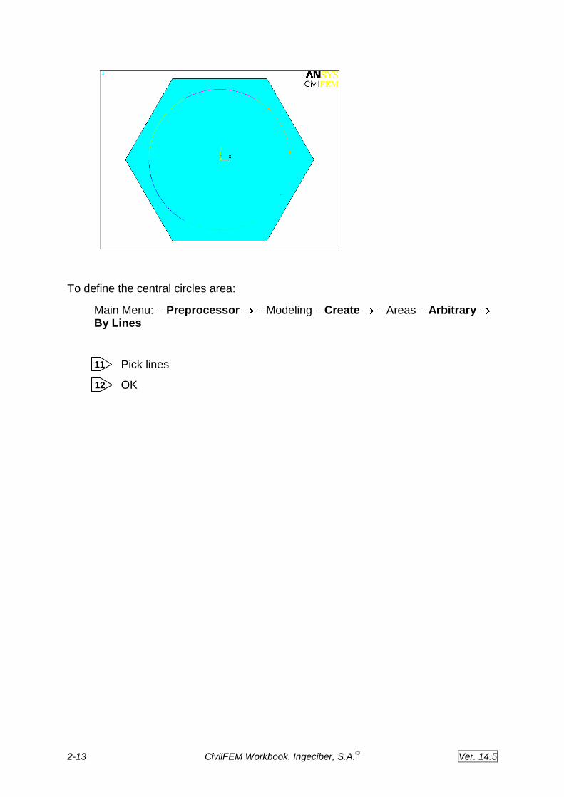
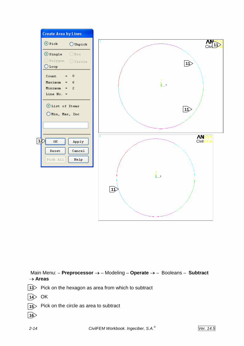
To define the central circles area:
Main Menu: Preprocessor Modeling Create Areas Arbitrary By Lines
Pick lines
OK
11
12
2-14 CivilFEM Workbook. Ingeciber, S.A.©
Ver. 14.5
Main Menu: Preprocessor Modeling Operate Booleans Subtract
Areas
Pick on the hexagon as area from which to subtract
OK
Pick on the circle as area to subtract
13
14
15
16
14
12
11
11
11
11
11
11

2-15 CivilFEM Workbook. Ingeciber, S.A.©
Ver. 14.5
OK
Now we divide the area by lines into six to allow mapped meshing.
Main Menu: Preprocessor Modeling Create Lines Lines
Straight line
Pick on the first keypoint
Pick on the second keypoint
OK to define line
17
18
19
13
14
15
16

2-16 CivilFEM Workbook. Ingeciber, S.A.©
Ver. 14.5
Repeating with the remaining keypoints we define the lines that we are going to use to divide de area of the section.
Main Menu: Preprocessor Modeling Operate Booleans Divide
Area by line
Pick the area to divide
OK
Pick on the lines dividing the area
OK
17 18
19
20
21
22
23

2-17 CivilFEM Workbook. Ingeciber, S.A.©
Ver. 14.5
224
224
224
224
224
224
20
21
25 23

2-18 CivilFEM Workbook. Ingeciber, S.A.©
Ver. 14.5
To control the mesh process we define the number of element divisions on each line.
Main Menu: Preprocessor Meshing Size controls Manual size
Lines Picked Lines
Pick the lines dividing the section
OK
Enter 1 as number of element divisions
Apply to continue selecting lines
257
268 279
246
246
26
246
246
246
257
246

2-19 CivilFEM Workbook. Ingeciber, S.A.©
Ver. 14.5
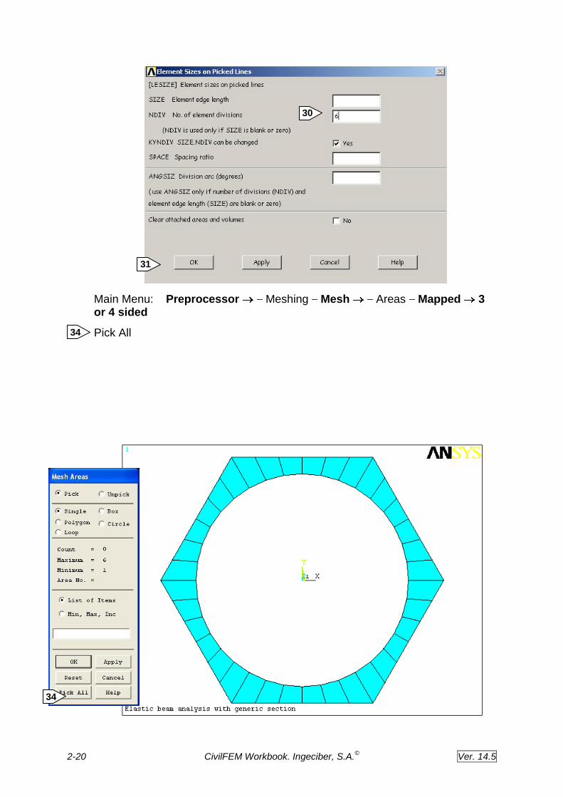
Pick on the rest of the lines
OK
Enter 6 as number of element divisions
OK
302 313
2830
2931
2830
2830
2830
2830
2830
2830
2830
2830
2830
2830’
2830
2830
2931
268
279
2-20 CivilFEM Workbook. Ingeciber, S.A.©
Ver. 14.5
Main Menu: Preprocessor Meshing Mesh Areas Mapped 3 or 4 sided
Pick All
34
33
302
314
34

2-21 CivilFEM Workbook. Ingeciber, S.A.©
Ver. 14.5
Once we have created the section with ANSYS we use the CivilFEM command ~SEC2DIN to import the section. We need a new local coordinate system to capture the section. It must contain the section on the YZ plane.
Utility Menu: WorkPlane Local Coordinate Systems Create Local
CS At specified Loc
Enter 0,0,0 as origin of coordinate system
OK
Enter 90 for angle of rotation about Y
OK
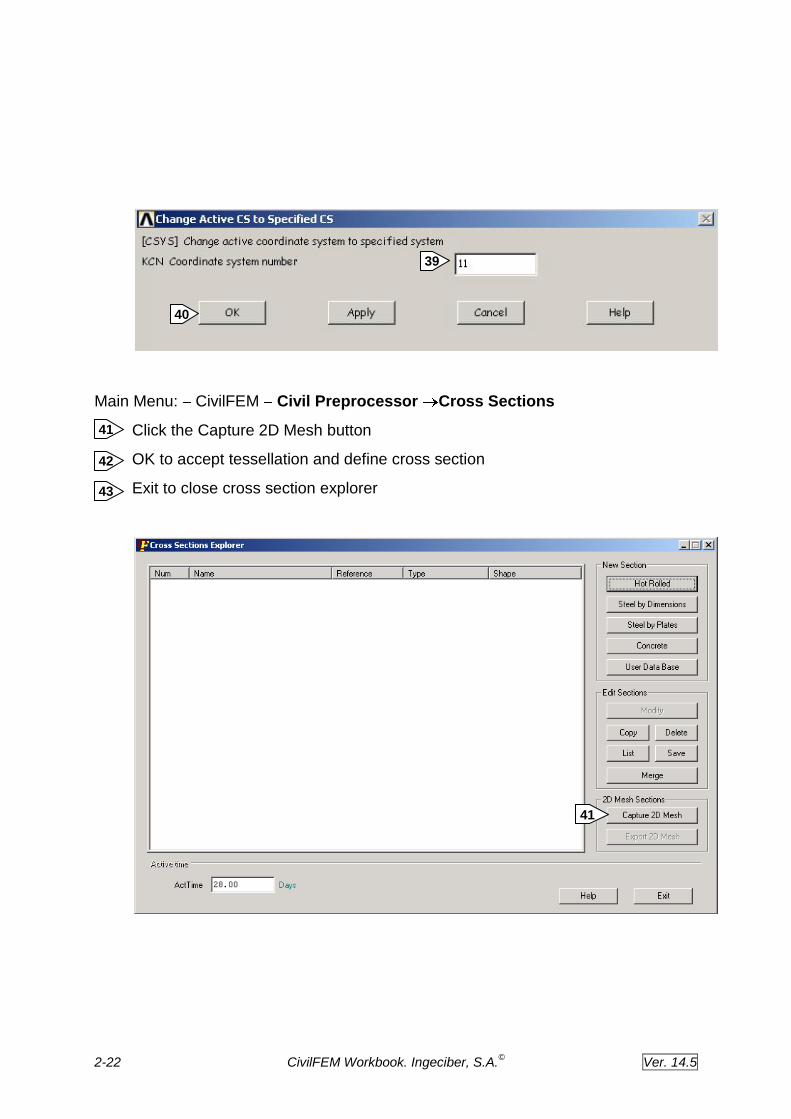
To activate this coordinate system:
Utility Menu: WorkPlane Change Active Cs to Specified coord sys…
Enter Coordinate system 11
OK
35
36
37
38
34
39
40
36
35
38
37
2-22 CivilFEM Workbook. Ingeciber, S.A.©
Ver. 14.5
Main Menu: CivilFEM Civil Preprocessor Cross Sections
Click the Capture 2D Mesh button
OK to accept tessellation and define cross section
Exit to close cross section explorer
41
41
42
43
39
40

2-23 CivilFEM Workbook. Ingeciber, S.A.©
Ver. 14.5
43
42

2-24 CivilFEM Workbook. Ingeciber, S.A.©
Ver. 14.5
To finish the process we delete all the geometric entities and elements that we have created to build the beam element model. First we clear the meshed areas.
Main Menu: Preprocessor Meshing Clear Areas
Pick All
Now delete the areas, lines and keypoints
Main Menu: Preprocessor Modeling Delete Areas and below
Pick All
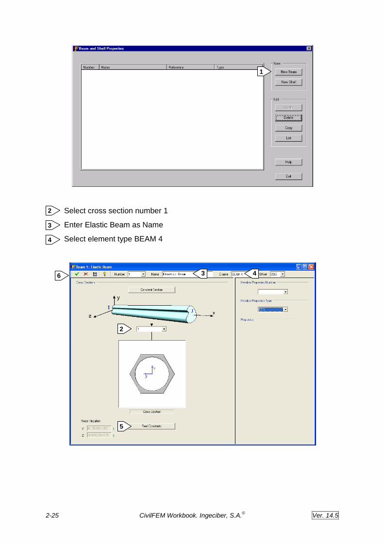
6. Define Beam & Shell properties
The CivilFEM command ~BMSHPRO will be used to define ANSYS real constants.
Main Menu: CivilFEM Civil Preprocessor Beam & Shell pro
Click the New Beam button
44
45
1
44 41
45
2-25 CivilFEM Workbook. Ingeciber, S.A.©
Ver. 14.5
Select cross section number 1
Enter Elastic Beam as Name
Select element type BEAM 4
1
2
3
4
2
3 4
5
6

2-26 CivilFEM Workbook. Ingeciber, S.A.©
Ver. 14.5
You can review ANSYS real constants modified by CivilFEM by clicking the Real Constants button
OK to define Beam & Shell properties
EXIT to close window
7. Define solid modeling entities
To create the model geometry we will use the ANSYS solid modeling tools.
6
7
7
5

2-27 CivilFEM Workbook. Ingeciber, S.A.©
Ver. 14.5
First, change the coordinate system
Utility Menu: WorkPlane Change Active Cs to Global Cartesian
Now we create keypoints.
Main Menu: Preprocessor Modeling Create Keypoints In Active CS
Enter 1 for first keypoint
Enter x=0, y=0, z=0 for coordinates of keypoint 1
Apply to create the first keypoint
Enter 2 for second keypoint
Enter x=33, y=0, z=0 for coordinates of keypoint
Ok
Use these two keypoints to generate a line.
Main Menu: Preprocessor Modeling Create Lines Straight Line
Pick keypoint 1 and keypoint 2
OK
1
2
1
2
3
3
4
5
6
7
8
4
6
5
2-28 CivilFEM Workbook. Ingeciber, S.A.©
Ver. 14.5
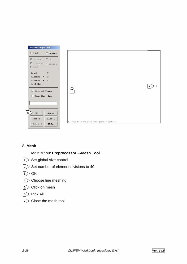
8. Mesh
Main Menu: Preprocessor Mesh Tool
Set global size control
Set number of element divisions to 40
OK
Choose line meshing
Click on mesh
Pick All
Close the mesh tool
1
1 2
Elastic beam analysis with generic section
7 7
5
7
1
2
3
4
6
8
7

2-29 CivilFEM Workbook. Ingeciber, S.A.©
Ver. 14.5
9. Save the database
Before moving to the next step, we will save all we have done so far. The save operation will save the database to file.db and file.cfdb.
Toolbar: CFSAVE
1
4
7
5
6
2
3

2-30 CivilFEM Workbook. Ingeciber, S.A.©
Ver. 14.5
Solution
10. Apply displacement constraints
Main Menu: Solution Define Loads Apply – Structural –
Displacement On Nodes
Pick node 1 at beam left end
OK to finish picking nodes
Choose UX, UY,UZ and ROTX
Apply 4
1
2
3
1
"Elastic beam analysis with generic section"
1
2
3
4
2-31 CivilFEM Workbook. Ingeciber, S.A.©
Ver. 14.5
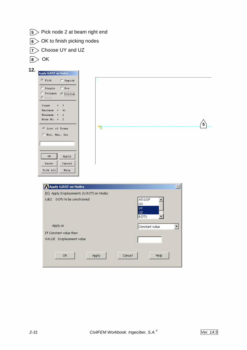
Pick node 2 at beam right end
OK to finish picking nodes
Choose UY and UZ
OK
12.
8
5
6
7
6
1
"Elastic beam analysis with generic section"
5
8
7
2-32 CivilFEM Workbook. Ingeciber, S.A.©
Ver. 14.5
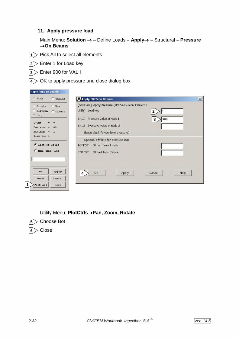
11. Apply pressure load
Main Menu: Solution Define Loads Apply Structural Pressure
On Beams
Pick All to select all elements
Enter 1 for Load key
Enter 900 for VAL I
OK to apply pressure and close dialog box
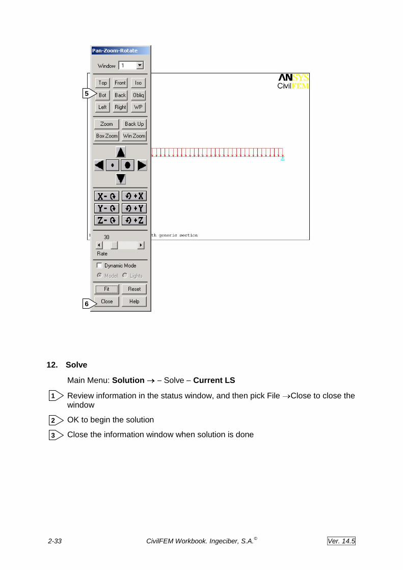
Utility Menu: PlotCtrls Pan, Zoom, Rotate
Choose Bot
Close
3
4
1
2
6
5
5
1
2
3
4
2-33 CivilFEM Workbook. Ingeciber, S.A.©
Ver. 14.5
12. Solve
Main Menu: Solution Solve Current LS
Review information in the status window, and then pick File Close to close the window
OK to begin the solution
Close the information window when solution is done
1
2
3
5
6

2-34 CivilFEM Workbook. Ingeciber, S.A.©
Ver. 14.5
1
2
3

2-35 CivilFEM Workbook. Ingeciber, S.A.©
Ver. 14.5
Postprocessing
Postprocessing is where you review the analysis results through graphic displays and tabular listings.
13. Enter the postprocessor and read results
You must select the load step from which you want to read the results data, from the CivilFEM results file. This results file contains the calculated forces, moments and stresses.
Main Menu: CivilFEM Civil Postprocess Read Results By Load Step
Enter 1 in the Load Step number box
OK to read load step 1
14. Plot the deformed shape
Main Menu: General Postproc Plot Results Deformed Shape
Choose Def + undef edge
OK
1
2
2
1
1
2
1
2
2-36 CivilFEM Workbook. Ingeciber, S.A.©
Ver. 14.5
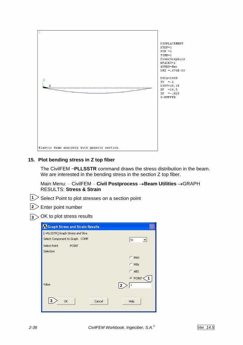
15. Plot bending stress in Z top fiber
The CivilFEM ~PLLSSTR command draws the stress distribution in the beam. We are interested in the bending stress in the section Z top fiber.
Main Menu: CivilFEM Civil Postprocess Beam Utilities GRAPH RESULTS: Stress & Strain
Select Point to plot stresses on a section point
Enter point number
OK to plot stress results
1
2
3
2
1
3

2-37 CivilFEM Workbook. Ingeciber, S.A.©
Ver. 14.5
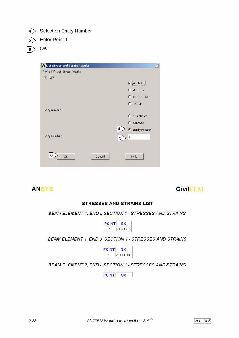
16. List bending stress in Z top fiber
Main Menu: CivilFEM Civil Postprocess Beam Utilities LIST RESULTS: Stress & Strain
Choose Both in order to list the stress at node I and J
Pick on Stress SX to list section stresses
OK
1
2
3
1
2
3
2-38 CivilFEM Workbook. Ingeciber, S.A.©
Ver. 14.5
Select on Entity Number
Enter Point 1
OK
4
5
6
4
5
6
2-39 CivilFEM Workbook. Ingeciber, S.A.©
Ver. 14.5
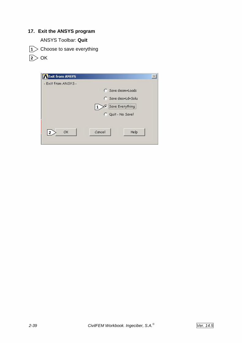
17. Exit the ANSYS program
ANSYS Toolbar: Quit
Choose to save everything
OK
1
2
1
2