2-d linear motion system - infohouseinfohouse.p2ric.org/ref/13/12706.pdf · doe/em-0403 2-d linear...
TRANSCRIPT

DOE/EM-0403
2-D Linear MotionSystem
Deactivation and Decommissioning Focus Area
Prepared for
U.S. Department of EnergyOffice of Environmental Management
Office of Science and Technology
November 1998
2-D LinearMotion System
OST Reference #1476
Deactivation and Decommissioning Focus Area
Demonstrated atHanford Site
Richland, Washington

Purpose of this document
Innovative Technology Summary Reports are designed to provide potential users with theinformation they need to quickly determine if a technology would apply to a particularenvironmental management problem. They are also designed for readers who mayrecommend that a technology be considered by prospective users.
Each report describes a technology, system, or process that has been developed and testedwith funding from DOE’s Office of Science and Technology (OST). A report presents the fullrange of problems that a technology, system, or process will address and its advantages to theDOE cleanup in terms of system performance, cost, and cleanup effectiveness. Most reportsinclude comparisons to baseline technologies as well as other competing technologies.Information about commercial availability and technology readiness for implementation is alsoincluded. Innovative Technology Summary Reports are intended to provide summaryinformation. References for more detailed information are provided in an appendix.
Efforts have been made to provide key data describing the performance, cost, and regulatoryacceptance of the technology. If this information was not available at the time of publication,the omission is noted.
All published Innovative Technology Summary Reports are available on the OST Web site athttp://ost.em.doe.gov under “Publications.”
TABLE OF CONTENTS
1. SUMMARY page 1
2. TECHNOLOGY DESCRIPTION page 5
3. PERFORMANCE page 8
4. TECHNOLOGY APPLICABILITY AND ALTERNATIVE TECHNOLOGIES page 16
5. COST page 17
6. REGULATORY AND POLICY ISSUES page 22
7. LESSONS LEARNED page 24
APPENDICES
A. REFERENCES
B. ACRONYMS AND ABBREVIATIONS
C. TECHNOLOGY COST COMPARISON

1 Wall Walker is a trademark of Pentek, Inc., Coraopolis, Pennsylvania.
Page 1
U.S. Department of Energy
EXECUTIVE SUMMARYThe 2-D Linear Motion System (2-D LMS), also known as the Wall WalkerTM1, is designed toremotely position tools and instruments on walls for use in such activities as radiation surveys,decontamination, and painting. Traditional (baseline) methods for operating equipment for thesetasks require workers to perform duties on elevated platforms, sometimes several meters abovethe ground surface and near potential sources of contamination. The Wall Walker 2-D LMSsignificantly improves health and safety conditions by facilitating remote operation of equipment. The Wall Walker 2-D LMS performed well in a demonstration of its precision, accuracy,maneuverability, payload capacity, and ease of use. Thus, this innovative technology isdemonstrated to be a viable alternative to standard methods of performing work on large, highwalls, especially those that have potential contamination concerns. The Wall Walker was usedto perform a final release radiological survey on over 167 m2 of walls. In this application,surveying using a traditional (baseline) method that employs an aerial lift for manual access was64% of the total cost of the improved technology. However, for areas over approximately 600m2, the Wall Walker would cost less than the baseline. Using the Wall Walker 2-D LMS, ALARAexposure and worker safety is improved, and there is potential for increased productivity. Thisinnovative technology performed better than the baseline by providing real-time monitoring of thetool or instrument position. Also, the Wall Walker 2-D LMS can traverse any two-dimensionalpath at constant speeds of up to 18.3 linear meters per minute (60 linear feet per minute). Thesurvey production rate for the innovative technology was about 0.6 m2/min (6 ft2/min); thebaseline production rate was approximately 0.3 m2/min (3 ft2/min), using the same surveyinginstrument and maximum scanning rate.
SECTION 1
ss Technology Summary
This section summarizes an improved technology thatcan be used to position tools and instruments remotelyon high, vertical surfaces (building interior and exteriorwalls). The 2-D Linear Motion System (2-D LMS), alsoknown as the Wall Walker™1, is a semi-robotic remoteoperating system that consists of motorized pulleys withcables hooked to a shroud or holder for the tool. Aprogrammable controller on the ground controls theprecise location and speed of the tool used.
Problem Addressed
The U.S. Department of Energy’s (DOE) nuclear facilitydecontamination and decommissioning (D&D) program requires buildings to be decontaminated, decommissioned, and surveyed for radiologicalcontamination in an expeditious and cost-effective manner. Simultaneously, the health and safety ofpersonnel involved in the D&D activities is of primary concern. D&D workers must perform duties highoff the ground, requiring the use of manlifts or scaffolding, often, in radiologically or chemicallycontaminated areas or in areas with limited access. Survey and decontamination instruments that areused are sometimes heavy or awkward to use, particularly when the worker is operating from a manliftor scaffolding. Finding alternative methods of performing such work on manlifts or scaffolding isimportant.

EXECUTIVE SUMMARY continued
Page 2
U.S. Department of Energy
The Wall Walker 2-D LMS allows D&D and survey instrumentation to be operated remotely from theground, eliminating the need for work on manlifts or scaffolds, and minimizing work in proximity tocontamination. In addition, the Wall Walker 2-D LMS provides a measure of precision and productivitythat is not available with the baseline method, i.e., manned operation of D&D and survey tools. Themodel demonstrated is designed for remotely operating tools weighing up to 158 kg (350 lb) andmodels are available for up to 909 kg (2,000 lb).
Potential Markets / Applicability
The Pentek, Inc. Wall Walker 2-D LMS is useful at DOE or other federal or commercial sites wheretools or instruments must be used on high, vertical, flat or slightly curved surfaces. Because it isremotely controlled, it is especially effective in areas that are contaminated or where personnel wouldotherwise be required to work from manlifts or scaffolding. Also, because the instruments can beinterfaced with computer software applications, the Wall Walker 2-D LMS is useful for performingsurveys in which an automatic mapping feature is desired.
Features and Components
& Two motorized pulleys temporarily mounted near top corners of the wall
& Two wire cables threaded through the pulleys to a tool holder/shroud
& Programmable controller at remote ground-level location controls motorized pulleys to providedesired position and speed of movement to the tool holder/shroud
Advantages of the Improved Technology
The following table compares the improved technology to the baseline in key areas:
Category Comments
Cost In this application, the baseline cost is 64% of Wall Walker;however, ALARA exposure and worker safety is improved.
Performance Production rate is about 0.6 m2/min (6 ft2/min) for a release survey;baseline production is about 0.3 m2/min (3 ft2/min). Accuracy inpositioning equipment was within 1% to 2%, speed control waswithin 7%, much better than baseline. Repeatability in relocatingequipment to specific positions was within 2.54 cm (1 in.), which iscomparable to baseline.
Implementation No special site services are required for implementing this tool.
Secondary Waste Generation Does not generate secondary waste.
ALARA/Safety Use of this tool improves ALARA conditions and safety, significantlyreducing exposure and risks of workers falling.
Ease of use Easy to deploy and control, short learning curve. Requires minimalskills.
EXECUTIVE SUMMARY continued
Page 3
U.S. Department of Energy
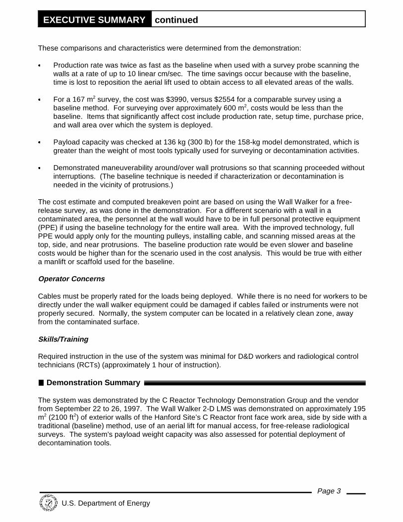
These comparisons and characteristics were determined from the demonstration:
& Production rate was twice as fast as the baseline when used with a survey probe scanning thewalls at a rate of up to 10 linear cm/sec. The time savings occur because with the baseline,time is lost to reposition the aerial lift used to obtain access to all elevated areas of the walls.
& For a 167 m2 survey, the cost was $3990, versus $2554 for a comparable survey using abaseline method. For surveying over approximately 600 m2, costs would be less than thebaseline. Items that significantly affect cost include production rate, setup time, purchase price,and wall area over which the system is deployed.
& Payload capacity was checked at 136 kg (300 lb) for the 158-kg model demonstrated, which isgreater than the weight of most tools typically used for surveying or decontamination activities.
& Demonstrated maneuverability around/over wall protrusions so that scanning proceeded withoutinterruptions. (The baseline technique is needed if characterization or decontamination isneeded in the vicinity of protrusions.)
The cost estimate and computed breakeven point are based on using the Wall Walker for a free-release survey, as was done in the demonstration. For a different scenario with a wall in acontaminated area, the personnel at the wall would have to be in full personal protective equipment(PPE) if using the baseline technology for the entire wall area. With the improved technology, fullPPE would apply only for the mounting pulleys, installing cable, and scanning missed areas at thetop, side, and near protrusions. The baseline production rate would be even slower and baselinecosts would be higher than for the scenario used in the cost analysis. This would be true with eithera manlift or scaffold used for the baseline. Operator Concerns
Cables must be properly rated for the loads being deployed. While there is no need for workers to bedirectly under the wall walker equipment could be damaged if cables failed or instruments were notproperly secured. Normally, the system computer can be located in a relatively clean zone, awayfrom the contaminated surface.
Skills/Training
Required instruction in the use of the system was minimal for D&D workers and radiological controltechnicians (RCTs) (approximately 1 hour of instruction).
22 Demonstration Summary
The system was demonstrated by the C Reactor Technology Demonstration Group and the vendorfrom September 22 to 26, 1997. The Wall Walker 2-D LMS was demonstrated on approximately 195m2 (2100 ft2) of exterior walls of the Hanford Site’s C Reactor front face work area, side by side with atraditional (baseline) method, use of an aerial lift for manual access, for free-release radiologicalsurveys. The system’s payload weight capacity was also assessed for potential deployment ofdecontamination tools.

EXECUTIVE SUMMARY continued
Page 4
U.S. Department of Energy
Regulatory Issues
The Wall Walker 2-D LMS is used to deploy instruments and tools, and there are no specialregulatory permits required for its use. This system can be used within the requirements of 10 Codeof Federal Regulations (CFR), Parts 20 and 835, and proposed Part 834 for radiological protection ofworkers and the environment, and Occupational Safety and Health Administration (OSHA) guidelines(29 CFR).
Technology Availability
The Wall Walker 2-D LMS technology demonstrated at the C Reactor was the first suchdemonstration for characterization at a DOE site. The system is available from Pentek, Inc.
Technology Limits/Needs for Future D evelopment
The Wall Walker model demonstrated was specified to reach wall dimensions of approximately 15 m(50 ft). Since the system would be useful for a variety of tools and Pentek, Inc. has designed only afew holders, additional holders would need to be developed to increase the utility of the system. This technology is not well suited to walls that have many protrusions; rather, it works better on flator slightly curved surfaces.
ss Contacts
ManagementJohn Duda, FETC, (304) 285-4217Jeff Bruggeman, DOE RL, (509) 376-7121Shannon Saget, DOE RL, (509) 372-4029
TechnicalStephen Pulsford, BHI, (509) 373-1769Gregory Gervais, USACE, (206) 764-6837
Licensing InformationSheldon Lefkowitz, Pentek, Inc., (412) 262-0725
OtherAll published Innovative Technology Summary Reports are available at http://em-50.em.doe.gov. TheTechnology Management System, also available through the EM50 web site, provides information about OSTprograms, technologies, and problems. The OST reference # for the 2-D Linear Motion System is 1476.
Page 5
U.S. Department of Energy
TECHNOLOGY DESCRIPTION
Figure 1. Wall Walker demonstration. Figure 2. Remote control station.
SECTION 2
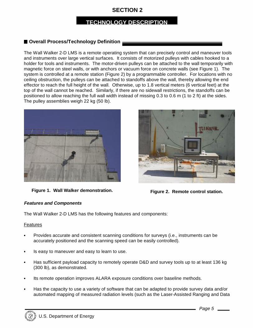
ss Overall Process/Technology Definition
The Wall Walker 2-D LMS is a remote operating system that can precisely control and maneuver toolsand instruments over large vertical surfaces. It consists of motorized pulleys with cables hooked to aholder for tools and instruments. The motor-driven pulleys can be attached to the wall temporarily withmagnetic force on steel walls, or with anchors or vacuum force on concrete walls (see Figure 1). Thesystem is controlled at a remote station (Figure 2) by a programmable controller. For locations with noceiling obstruction, the pulleys can be attached to standoffs above the wall, thereby allowing the endeffector to reach the full height of the wall. Otherwise, up to 1.8 vertical meters (6 vertical feet) at thetop of the wall cannot be reached. Similarly, if there are no sidewall restrictions, the standoffs can bepositioned to allow reaching the full wall width instead of missing 0.3 to 0.6 m (1 to 2 ft) at the sides. The pulley assemblies weigh 22 kg (50 lb).
Features and Components
The Wall Walker 2-D LMS has the following features and components:
Features
& Provides accurate and consistent scanning conditions for surveys (i.e., instruments can beaccurately positioned and the scanning speed can be easily controlled).
& Is easy to maneuver and easy to learn to use.
& Has sufficient payload capacity to remotely operate D&D and survey tools up to at least 136 kg(300 lb), as demonstrated.
& Its remote operation improves ALARA exposure conditions over baseline methods.
& Has the capacity to use a variety of software that can be adapted to provide survey data and/orautomated mapping of measured radiation levels (such as the Laser-Assisted Ranging and Data

TECHNOLOGY DESCRIPTION continued
Page 6
U.S. Department of Energy
System [LARADS]).
& The holder can be retrofitted to operate a variety of survey or decontamination tools.
Components
& Two high-strength steel cables, managed by servo-motor-driven pulleys.
& A device suitable for holding the tool or instrument that is attached to each cable with a yokeand clevis.
& The holding device used for holding decontamination tools or scanning instruments is a shroud,fitted with casters for smooth traversing, that is held against the wall with either vacuum force orwith out-rigged weights.
& A vacuum hose fitting in the shroud to accommodate vacuum force and/or high-efficiencyparticulate air (HEPA) filtration system.
& A programmable controller at ground level with touch-screen controls and appropriate software.
The programmable controller demonstrated was programmed by Pentek using Parasol II software on adesktop computer. The maximum distance between the remote control station and the wall was set bythe cable length, which was 15.2 m (50 ft) for the demonstration. Presently, Pentek uses a personalcomputer (PC) in the field instead of a programmable controller. The new computer is Pentium basedwith Windows 95 operating system and a modem that allows placement of the control system at anydesired distance from the wall via telephone wires.
The operator can command the system (see Figure 2) to traverse any two-dimensional path atconstant speeds of up to 18 m/min (60 ft/min). Using the programmable controller, the operator caneither pre-program the pathways or manually guide the traverses. The motions can readily berehearsed prior to applying the tool. A device suitable for holding the tool or instrument and that isattached to each cable with a yoke and clevis must be obtained from the vendor or fabricatedespecially for the intended service. Pentek has standard tool holders with shrouds available for avariety of decontamination/characterization devices. The shroud is held against the wall with eithervacuum force or with out-rigged weights and is fitted with casters for smooth traversing. For example,an aggressive concrete decontamination tool can be held in a shroud with a vacuum hose that isconnected at ground level to a filtration unit. If the wall has protrusions (e.g., piping or conduit runs), atether attached to the shroud can be manually manipulated at ground level to temporarily pull the endeffector away from the wall. Present Pentek system designs can operate with shroud/toolcombinations weighing up to 453 kg (1,000 lb). Potential applications of the system include radiationsurveys, marking designated areas, decontamination, and painting.
Two high-strength steel cables are managed by servo-motor-driven pulleys that are attached orsuspended to the upper left and right sides of the wall. Both cables are joined together near a singlepoint where the end effector is attached. The length of each cable is precisely controlled by acomputer that directs the pulley motors. With the software employed in the Pentek Wall Walker 2-DLMS, the lengths of each of the two cables are known from automatic monitoring of the cable lengthspaid out or retrieved. The position of the tool holder is displayed as X-Y coordinates. The operatorarbitrarily chooses the location of the X-Y origin -- typically the lower left corner of the surface. Software is used to correct for cable stretch in computing X-Y positions. The wall span and height that

TECHNOLOGY DESCRIPTION continued
Page 7
U.S. Department of Energy
can be reached by the end effector is limited only by the length of cable furnished.
ss System Operation
Physical setup of the system was performed mainly by onsite personnel. The automatic positioning ofthe shroud holding the radiation detector was performed mainly by Pentek personnel; onsite personnelmounted pulleys and operated radiological survey instruments. The onsite personnel also receivedinstruction from the Pentek personnel and practiced operating the linear motion system.
Setup Procedure
- Unpack equipment, set computer on a stand or table, and connect electric power.
- Set anchors in top corners of wall and bolt base plates and pulley motors.
- Thread cables through pulleys and connect to tool holder or shroud.
- Mount tool or instrument. If a vacuum filtration unit is to be used, connect vacuum hose to shroud. Ifsurveying is to be done, set up detector communication system.
- Register zero-zero coordinates position, set corners coordinates of area on wall desired to bescanned,pattern of movement and speed at computer.
Scanning
- Start and run until desired area has been completed.
- Set next corners coordinates and pattern of movement, and start again. When all the desired areashave been completed, disconnect and remove cables.
Page 8
U.S. Department of Energy
PERFORMANCE
SECTION 3
ss Demonstration Plan/Overview
Demonstration Site Description
At its former weapons production sites, the DOE is conducting an evaluation of innovativetechnologies that might prove valuable for facility D&D. As part of the Hanford Site Large-ScaleDemonstration and Deployment Project (LSDDP) at the C Reactor Interim Safe Storage (ISS)Project, at least 20 technologies have been assessed against baseline technologies currently in use. DOE’s Office of Science & Technology/Deactivation and Decommissioning Focus Area, incollaboration with the Environmental Restoration Program, is undertaking a major effort ofdemonstrating improved and innovative technologies at its sites nationwide. If successfullydemonstrated at the Hanford Site, these innovative technologies could be implemented at otherDOE sites and similar government or commercial facilities. The technology demonstration wasconducted with Pentek personnel assisted by the DOE, Richland Operations Office (RL)Environmental Restoration Contractor (ERC), Bechtel Hanford, Inc. (BHI).
The demonstration was carried out September 22-26, 1997 at the C Reactor to conduct free-releasesurveys of large wall areas, and to assess the potential for the innovative technology to deploydecontamination tools. The primary objectives of the demonstration, key demonstration results, anda comparison of the innovative and baseline technologies are discussed in this section. Thedemonstration was carried out at the outer walls of the C Reactor front face work area. The wallsinvolved were 14.3 m (47 ft) high by 4.3 to 18.3 m (14 to 60 ft) wide, and had previously beensurveyed only near ground level up to 2.4 m (8 ft) high. The radiological detection system used wasan Eberline 380 alpha and beta/gamma probe with an Eberline 600 meter. Readings of radiationlevels were transmitted automatically by radio to a portable ground-based LARADS receiving stationand computer that operated independently from the LMS.
Demonstration Objectives
Specific performance objectives included the following features:
& Ability to provide robotic positioning and travel on walls guided by both a programmablecomputer and a manually controlled work station (joy stick), at least 15.2 m (50 ft) distance fromthe wall, that remotely controls movement of survey (characterization, pre- and post-decon,etc.) instrumentation probes and decontamination tools.
& Ability to deploy one of the baseline decontamination tools and survey probe on at least twowalls to evaluate operation and setup.
& Capable of lifting and moving probes and tools with their associated hoses and cables to aheight of 12.2 m (40 ft), and coverage of a wall 15.2 m (50 ft) wide with one setup. The locationprecision shall be + 2.5 cm (1 in.). Computer control shall be capable of positioning a workingtool on a vertical surface with a repeatability within 0.16 cm (1/16 in.).
& Ability to lift and move working loads with maximum weight of 159 kg (350 lb).
& Easy to decontaminate with conventional equipment.
PERFORMANCE continued
Page 9
U.S. Department of Energy
& Ability to operate in an ambient temperature environment from 3°C to 40°C.
Demonstration Chronology
The radiation detector and automatic mapping system used was the LARADS, which was also usedfor the demonstration of the baseline method. Although the Wall Walker 2-D LMS computer couldbe adapted to perform mapping, during the demonstration it was used only for automaticallypositioning the radiation detector and setting the scanning speed. For the baselinedemonstration, exterior concrete walls of the same height at the same building complex wereused. Required duration times for each task, such as setup, survey, and take down, wererecorded. The demonstration was conducted as follows:
Improved Technology
& The equipment was unpacked and set up on September 22-23, 1997. Onsite personnel wereinstructed by a vendor technician for a portion of the work. An RTC and D&D workers quicklylearned the mechanical assembly and computer touch-screen control techniques. (Instructiontook less than 1 hour, and it is estimated that complete adeptness could be achieved with anadditional 3 hours of practice.)
& The Wall Walker 2-D LMS motorized pulleys were mounted near upper wall corners as wouldbe done for deployment on interior walls with ceiling and corner interferences. With thisconfiguration, 1.8 m (6 ft) of wall at the top and up to 0.9 m (3 ft) of wall at each side were notaccessed by the Wall Walker 2-D LMS. Such areas that were omitted and areas nearprotrusions can be surveyed using the baseline method. In this case, the aerial lift used to aidin mounting the pulleys would be the choice for accessing areas needing manual surveying. The pulley assemblies were mounted by bolting them to concrete anchors after a manualradiation survey was performed at each mounting area.
& The radiation detector was mounted in a custom-fabricated shroud that was counter-weightedto cause pressure against the wall. The shroud was also fitted with casters, which were set toprovide 0.6-cm (0.25-in.) standoff from the wall. (The shroud also had a vacuum hose fitting inthe event vacuum force and/or HEPA filtration were desired.) Cable length was furnished forthis demonstration sufficient to access walls up to 12 m (40 ft) wide by 15 m (50 ft) high. Thecables were threaded through the pulleys by accessing with the aerial lift, and attached to theshroud at ground level. A rope attached to the shroud was used to manually pull the assemblyover and around protrusions.
& Wall surveys, accuracy checks, and speed checks were done on September 24-25, 1997.
& The payload determination and packing for return shipment to the vendor were conducted onSeptember 26, 1997.
Baseline Technology
The same aerial lift used to mount pulleys was deployed at an adjacent wall with a D&D worker andan RCT several days after the demonstration of the improved technology.
ss Technology Demonstration Results

PERFORMANCE continued
Page 10
U.S. Department of Energy
Successes
& Used for survey of 195 m2 (2,100 ft2 ) of wall area at a pre-set standoff distance from the wall.
& The system was simple to deploy and the end effector was readily maneuverable around thedesired walls area and over protrusions.
& Positioning accuracy was within 1% to 2%.
& Repeatability was within 2.5 cm (1 in.).
& Speed accuracy was within approximately 7%.
& The cable and pulley system furnished was rated at 158 kg (350 lb) payload, and wassuccessfully demonstrated with a 136 kg (300 lb) payload.
Shortfalls
& The Wall Walker 2-D LMS is not suitable for surfaces that have many obstructions such aspiping or conduit, because the wall area adjacent to such protrusions is missed.
& Currently, only a few shrouds are available to hold tools, which limits the number and type oftools that could be employed with the system. However, the technology provider should beconsulted as they may be able to adapt the shroud to meet a user’s specific need. The holderdeployed was somewhat awkward to use.
Meeting Performance Objectives
The Wall Walker met the objectives listed in the Demonstration Overview section with the followingexceptions and qualifications.
& The model furnished used a programmable controller instead of a computer. The programmingwas accomplished at the vendor’s headquarters with a desktop computer. This arrangementproved to be adequate.
& Joy stick control was not demonstrated. The programmable controller with touch-screencontrols proved to be adequate as demonstrated.
& Decontamination (concrete surface removal) tools were not demonstrated.
& Using the Wall Walker on a 15.2-m-wide wall with one setup was not demonstrated, but thecable lengths provided were capable of doing this.
& Repeatability of positioning was accurate to within 2.5 cm (1 in.), not 0.16 cm (1/16 in.), and isconsidered adequate for most survey and decontamination tasks on large walls surfaces.
PERFORMANCE continued
Page 11
U.S. Department of Energy
& The system was tested with 136 kg of weights, not 158 kg. The wall decontamination toolsused at the site weighed less than 136 kg. The vendor can supply cables and pulley motorsrated for 909 kg (2,000 lb).
ss Comparison of Improved Technology to Baseline
Surveying with the Wall Walker 2-D LMS
Approximately 195 m2 (2,100 ft2) of wall area was surveyed. An 18-m- (60-ft-) wide wall wassurveyed in two sections, each approximately 9 m (30 ft) wide. An 8-m- (27.5-ft-) wide section ofanother wall was surveyed. A demonstration of payload capability was conducted at a third wall. The target scanning speed for the 15.2-cm- (6-in.-) high radiation detector employed was 10.2cm/sec (4 in./sec), with a 5.1-cm (2-in.) overlap for each horizontal scan that was performed, with thehorizontal scanning speed set at 10.2 cm/sec (4 in./sec). The maximum production rate with theseconditions is 0.6 m2/min (6.7 ft2/min). The survey production rate averaged 0.6 m2/min (6 ft2/min). The theoretical maximum production rate of 0.6 m2/min (6.7 ft2/min) was not attained because theWall Walker 2-D LMS pauses slightly prior to each vertical move. Based on the measureddurations, the setup/takedown time plus survey time would equal the baseline survey duration withthe Wall Walker 2-D LMS deployed over 24.4 m2 (263 ft2). Approximately 5% of the wall areascovered was not scanned because of interfering protrusions; baseline surveying techniques (withthe same aerial lift used to install the Wall Walker 2-D LMS pulleys) could be used for these areas.
The demonstration also showed that the positioning accuracy was within 1% to 2%, repeatabilitywas within 2.5 cm (1 in.), and speed accuracy was within approximately 7%. These features wereassessed using the following methods:
& Positioning accuracy was determined by entering desired coordinates into the systemcomputer, allowing the system to automatically move the shroud accordingly, and checking thelocation physically. This routine was done again for three additional locations.
& Repeatability was determined by entering desired coordinates into the system computer,allowing the system to automatically move the shroud accordingly, and checking the locationphysically. This routine was repeated three additional times.
& Speed accuracy was determined by entering a desired travel speed into the system computer,allowing the system to automatically move the shroud accordingly, and checking the distancetraveled and time manually.
To assess the potential for the system to be used for decontaminating walls, the following approachwas used. The cable and pulley system furnished was rated by Pentek at 158 kg (350 lb) payload. Typical tools used routinely for aggressive concrete surface decontamination, such as scrabblersand vacu-blasters, weigh less than 136 kg (300 lb). The system was successfully demonstrated with136 kg (300 lb) payload. This was accomplished by removing the shroud used to house theradiation detector and adding six 22.7-kg (50-lb) weights in its place. The system was then directedfrom the computer to move the weights horizontally, vertically, and diagonally over distances ofapproximately 6 m (20 ft) in each direction.
Onsite personnel were instructed by a vendor technician for a portion of the work. An RCT and D&Dworkers quickly learned the mechanical assembly and computer touch-screen control techniques.
PERFORMANCE continued
Page 12
U.S. Department of Energy
Baseline Technology
The baseline method is to place personnel in proximity to the wall using scaffolding, aerial lifts, orscissor lifts. Exterior concrete walls of the same height and at the same building complex as wereused for the innovative technology were surveyed. An aerial lift was used to provide technicianaccess to a 14-m- (47-ft-) high exterior concrete wall for a release survey. (The same accessmethod is used routinely for high interior walls.) The same radiation detector and automaticmapping system (LARADS) were used in the baseline demonstration as were employed for thedemonstration of the Wall Walker 2-D LMS. The area surveyed was 4 m (14 ft) wide by 8 m (27 ft)high, near the top of the wall. As with the improved technology demonstration, the target scanningspeed for the 15.2-cm- (6-in.-) high radiation detector was 10.2 cm/sec (4 in./sec), with a 5-cm (2-in.)overlap for each horizontal scan that was performed. The maximum production rate with theseconditions is 2 m/min (6.7 ft/min). The actual production rate was 0.95 m/min (3.1 ft/min), allowingfor overlaps that exceeded 5 cm (2 in.) and time lost due to intermittent repositioning of the aerial liftand 10% break time to rest fatigued arms. Essentially all of the wall that was to be surveyed (115.3m [378 ft]) was surveyed with this method, and no substantial setup time or takedown time wasrequired.

PERFORMANCE continued
Page 13
U.S. Department of Energy
Table 1 summarizes performance and operation of the innovative technology compared to thebaseline technology.
Table 1. Comparison of improved and baseline technologies
Activity or Feature Improved Baseline
Setup and take downtimea (min)
45 5
Scanning rate 0.56 m2/min (6.0 ft2/min) 0.30 m2/min (3.1 ft2/min)
Scanning accuracy Very accurately set scanningspeed and overlap
Speed and overlap dependson RCT’s judgement
Flexibility Note b Note b
Safety and ALARA Workers and RCTs can stay at theground level and far from theproximity to potentially highradiation exposure or highradioactive contamination
Personnel must work at high elevationsin proximity to potentially high radiation
exposure or high radioactivecontamination
Durability Computer, cables, and pulleys aresubject to failures
More durable than innovativetechnology, less components
associated with it that are subject tofailure (but manlift still subject to
failure)
Ease of operation Not difficult to operate. Shroudsand tool holders need careful
design
Easy, but leads to worker fatigue
Waste generation None None
Utility requirements 120 VAC None
Training Minutes of instruction on coordinatesystem, threading cables through
pulleys and attaching it to theshroud, touch-screen computer
operation
Minimal, operation and fall protection
NOTES:a. Average timeb. The improved technology is flexible in terms of utilization of wide variety of instruments and tools.
However, the baseline technology virtually has no limitation in this regard and is more flexible wherethere are protrusions. When the weight of instruments and tools are beyond the two-man lifting limitas prescribed by OSHA regulations, the improved technology can handle more weight.
Because of its variety of functions and facilities, the DOE complex presents a wide range of D&Dwork conditions. The working conditions for an individual job directly affect the manner in which D&Dwork is performed for an individual job. The innovative and baseline technology evaluationspresented in this report are based upon a specific set of conditions or work practices present at the

PERFORMANCE continued
Page 14
U.S. Department of Energy
Hanford Site, and are listed in Table 2. This table is intended to help the technology user identifywork item differences between improved and baseline technologies.
Table 2. Summary of variable conditions
Variable Improved Baseline
Scope of Work
Quantity and Type Characterization of wall area of167.2 m2 (1,800 ft2 )*
Characterization of 35.1 m2 ( 378 ft2) areaactually performed, the cost analysis isbased on an assumed 167.2 m2 (1800 ft2
)
Location West and south side outer walls ofFront Face Work Area
North outer wall of Front Face Work Area
Nature of Work Survey of elevated and difficult to reachareas (height ranges from 5.8 m to 14.3m [19 ft to 47 ft] above ground level)and wall width exceeded Wall Walker 2-D LMS span limits (could not cover witha single setup)
Survey of elevated and difficult to reachareas (height ranges from 5.8 m to14.3 m [19 ft to 47 ft] above ground level). All work areas accessed by manlift
Work Environment
Worker Protection Hard hat, safety glasses, boots, andcoveralls (non-rad zone)
Same
Level ofContamination
Assumed to be a buffer zone Same
Work Performance
Acquisition Means Site workers and equipment Site workers and equipment
Production Rates 33.2 m2/hr (358 ft2/hr) 17.3 m2/hr (186 ft2/hr)
Equipment andCrew
Anchors installation - manlift, two D&Dworkers and RCT (during survey of theinstallation area only)Survey - Wall Walker, LARADS, RCTand one D&D worker (may include amanlift on standby)
Two RCTs, one D&D worker, manlift, andLARADS

PERFORMANCE continued
Page 15
U.S. Department of Energy
Work ProcessSteps
& Transport manlift and Wall Walker2-D LMS from storage area
& Set up equipment (i.e., Wall Walker2-D LMS PC and LARADS)
& Install anchor bolts and pulleys& Connect cable and tool
holder/shroud& Survey& Decontaminate and release& Transport equipment back to
storage area
& Transport manlift from storage area& Set up equipment (i.e., LARADS)& Survey& Decontaminate and release& Transport equipment back to storage
area
* Even though during this demonstration 195 m2 (2,100 ft2) was surveyed, only 167.2 m2 (1,800 ft2) of thearea was used for detailed comparisons because only 167.2 m2 (1,800 ft2) of the survey area wastimed precisely.
Skills/Training
Required instruction for D&D workers and RCTs in using the system was minimal (less than 1 hourof instruction plus 3 hours of practice would be needed if deployed). Workers and RCTs neededbasic knowledge of simple coordinate systems and needed to learn how to thread cable through thepulleys and to use the system computer touch-screen controls.
Operational Concerns The main mechanical/structural concerns involve ensuring proper rating of cables employed for thepayload and ensuring secure mounting of pulleys and associated instruments and tools. In mostapplications, there is no need for workers to be under the instrument or tool being deployed, so theywould not be injured if components fell. However, expensive equipment could be damaged if cablesfailed or instruments were not properly secured. Also, if this system is used in radiologicallycontaminated areas, proper radiological work practices and engineering controls should be taken toprevent personnel or any system components from becoming contaminated. Normally, the systemcomputer can be located in a relatively clean zone, away from the contaminated surface.

Page 16
U.S. Department of Energy
TECHNOLOGY APPLICABILITY ANDALTERNATIVE TECHNOLOGIES
SECTION 4
ss Technology Applicability
& This technology can be used at DOE and other public and commercial sites where large verticalsurfaces must be decontaminated, surveyed, washed, marked, or painted.
& This technology is effective at radiologically and non-radiologically contaminated sites especiallywhere personnel are required to wear protective equipment and/or perform tasks in high areas,or in areas with difficult access that otherwise would require lifts or scaffolding.
& The Wall Walker 2-D LMS can be used both inside and outdoors.
& This technology is well suited for applications of on-line characterization or decontaminationtools and equipment.
ss Competing Technologies
This technology competes with other simple 2-D linear motion systems (window washers, paintingsystems, etc.), scaffolding, and manlifts. The competing technologies do not provide computerizedpositioning of the instrumentation; rather visual line of site is used. Therefore, competingtechnologies are not as effective at providing information for proactive decision-making regardingcharacterization and decontamination management.
ss Patents/Commercialization/Sponsors
This technology is patented and commercially available through Pentek, Inc.
Page 17
U.S. Department of Energy
COST
SECTION 5
ss Introduction/Methodology
This cost analysis compares the Wall Walker 2-D LMS innovative technology to the baselinetechnology of conventional radiological surveying. The principal focus of this cost analysis is thecomparison of the delivery system (remote-controlled robotic system versus manual), and theradiological survey components are one potential aspect of the various D&D work activities thatmight be served by this technology. The improved technology was demonstrated using thevendor’s personnel; however, the estimate is based on using site personnel, and assumesGovernment-owned equipment (the estimate was not adjusted for worker learning curve). Thebaseline technology was performed and estimated using site labor and equipment. The productionrates and durations from the demonstration were used to estimate the cost of performing the surveyof the exterior reactor wall. Both technology demonstrations were performed using the LARADS, butany delays in productivity caused by breakdown of the LARADS were excluded from the costanalysis. The estimated cost for characterization by the conventional radiological survey method isapproximately 64% of the estimated cost for performing the characterization using the Wall Walker2-D LMS technology. Details of the cost comparison are presented in Appendix C of this report andsummarized in Figure 3.
ss Cost Analysis
The innovative technology is available from the vendor by purchase or vendor-provided service atthe rates indicated in Table 3:
Table 3. Improved technology acquisition costs
Acquisition Option Item Cost
Equipment Purchase Equipment & Accessories $120,000
Vendor-Provided Service Crew & Equipment DailyRate
$3,000/day
The rates and prices shown (provided by the test engineer) do not include shipping or mobilizationcosts. The prices will vary from those shown because of shipping/mobilization distance andcircumstances of the individual job (such as period of work). Rental/Lease is also an acquisitionoption in which the vendor would provide instruction. The vendor will provide current prices uponrequest.
Observed production rates and unit costs and production rates for principal components (setup andsurvey) of the demonstrations for both the innovative and baseline technologies are presented inTable 4:

COST continued
Page 18
U.S. Department of Energy
Table 4. Summary of production rates and unit costs
Improved Technology Wall Walker 2-D LMS
Baseline TechnologyManual Radiological Surveys
ProductionRate
Unit Cost Production Rate Unit Cost
SurveyAnchor/SetupTake Down
33 m2 / hour(360 ft2/hour)
$3.92/m2
($0.36/ft2)$280/ each set$40/ each set
17 m2 / hour(185 ft2/hour)
$8.71/ m2 ($0.80/ft2
The unit costs and production rates do not include mobilization, demobilization, daily meetings, andproductivity loss. The unit cost for Wall Walker 2-D LMS does not include the cost for LARADS,which was used to record the survey data, but is an optional cost (work could have been performedwithout using LARADS with the Wall Walker 2-D LMS).
The demonstration occurred under specific conditions that directly control cost (detailed tables ofcosts for the individual technologies are shown in Appendix C for the reader to compute the costs forsite-specific quantities). The most significant conditions affecting costs and production rates for thisdemonstration were as follows:
& Survey of elevated and difficult to reach areas (height ranges from 5.8 m to 14.3 m [19 ft to 47 ft]above ground level)
& Wall width exceeded limits of cable length used (could not cover with a single setup)
& Number of obstructions impacted number of setups required
& Type of tool being deployed.
For additional discussion of cost variable conditions that may occur when using the innovativetechnology and the potential effect these conditions may have on unit costs and production rates,refer to Section 3 of this report.
ss Cost Conclusions
The durations and production rates observed from the demonstration were used along with thesurface area quantity from an exterior reactor wall to estimate the cost of surveying thecontaminated surfaces. Some of the demonstrated activities were not included in the cost estimate(such as training for site operators and preliminary surveys to locate the “hot spots”). The estimatedcosts for the innovative technology and the baseline technology are shown in Figure 3, whichincludes extrapolated values for walls areas up to 929 m² (10,000 ft²). The costs are based on thefollowing work activities:
& Transport from storage area& Set up equipment & Survey& Decontaminate and release

COST continued
Page 19
U.S. Department of Energy
& Transport back to storage area.
The costs shown in Figure 3 do not include overhead or General and Administrative markup costs.

COST continued
Page 20
U.S. Department of Energy
$-
$2,000
$4,000
$6,000
$8,000
$10,000
$12,000
0 2000 4000 6000 8000 10000 12000
Job Size (square feet)
Tot
al C
ost (
$) Innovative
Baseline
Note: Multiply square feet by 0.093to obtain square meters.
Figure 3. Estimated costs for innovative and baseline technologies.
The extrapolation to 930 m2 (10,000 ft2 ) assumes that there are six sets of anchor installations for theWall Walker 2-D LMS and four repositions of the manlift for the baseline.
The estimate for this demonstration was based on three setups of the Wall Walker 2-D LMS becauseof the geometry of the areas being surveyed. The additional time required for installation of theanchors and attachment of the pulleys off-set the higher production rate and smaller crew size affordedby the Wall Walker 2-D LMS for the observed work (survey of 167.4 m2 [1,800 ft2]). The cost differencebetween Wall Walker 2-D LMS and the baseline would be greater than the amount shown in thisestimate if the Wall Walker 2-D LMS costs were based on a vendor-provided service rather than onGovernment ownership. This is a significant factor considering the purchase price of $120,000.
During the demonstration, the Wall Walker 2-D LMS missed a maximum of 41% of the survey areabecause of obstructions. This estimate does not account for the areas that could not be reached(additional cost for survey by conventional methods).
The baseline used an aerial lift (manlift) to maneuver around the wall. The manual radiological surveymissed less than 5% of the survey area because of obstructions. The costs for manual survey will varydepending on each individual D&D project. For example, it is possible that scaffolding would be

COST continued
Page 21
U.S. Department of Energy
required if other sites have areas not accessible by the aerial lift. Two carpenters at $45.85/hr wouldtake approximately 3 hours to erect 8.2 m (27 ft) of scaffolding. As a result, the cost of manualradiological surveying would be significantly increased due to a scaffolding erection costs and due to adecrease in productivity associated with working from scaffolds.
The costs for both the Wall Walker 2-D LMS and the baseline technology are significantly affectedby the geometry of the wall being surveyed. The geometry will determine the number of anchorinstallations and setups required for the Wall Walker 2-D LMS. For the baseline, the geometry ofthe wall will determine the number of times the manlift is repositioned or if scaffolding is required.
The Wall Walker 2-D LMS is capable of being equipped with a variety of attachments, includinghigh-pressure blasting nozzles, concrete scabblers, paint heads, inspection cameras, radiationsurvey devices, and robotic grip actuators. In addition, the remote control and robotic capabilitieseliminate some of the safety concerns involved with D&D work. Despite the determination that theWall Walker 2-D LMS does not provide savings for the quantity of work in this demonstration, othertypes of work could result in cost savings. Specifically, those walls with geometry that make manualwork difficult or pose a safety issue for the manlift could be cost-effective candidates if the numberof Wall Walker 2-D LMS anchor installations can be minimized.

Page 22
U.S. Department of Energy
REGULATORY AND POLICYISSUES
SECTION 6
ss Regulatory Considerations
& The linear motion system is used for remotely controlling instruments and tools. There are nospecial regulatory permits required for its operation.
& This system can be used in daily operations within the requirements of 10 CFR, Parts 20 and835, and proposed Part 834 for radiological protection of workers and the environment, andOSHA guidelines (29 CFR).
& Although the demonstration took place at a Comprehensive Environmental Response,Compensation, and Liability Act (CERCLA) site, no CERCLA requirements apply to thetechnology demonstrated.
ss Safety, Risk, Benefits, and Community Reaction
Worker Safety
& Precautions are needed to ensure that pulleys are mounted securely, that cables are ratedappropriately and inspected/replaced as needed, and that personnel are not working beneaththe system, thereby avoiding being hit by equipment if it falls.
& Normal radiation protection worker safety instructions used at the facility would apply when usedin radiologically controlled areas.
& Technology users should implement contamination control practices when used in contaminatedor potentially contaminated areas.
& Normal electrical safety and grounding requirements should be met.
& Normal worker safety precautions and practices prescribed by OSHA for operation of equipmentshould be followed.
Community Safety
& Implementation of the Wall Walker 2-D LMS is not anticipated to present any adverse impacts tocommunity safety.
ss Environmental Impact
& No adverse impact on the environment would be expected to occur with implementation of theWall Walker 2-D LMS.

REGULATORY/POLICY ISSUES continued
Page 23
U.S. Department of Energy
ss Socioeconomic Impacts and Community Perception
& No socioeconomic impacts are anticipated due to implementation of the Wall Walker 2-D LMS. The community should favorably accept the use of such a system, as it increases worker safetyand improves ALARA practice.
Page 24
U.S. Department of Energy
LESSONS LEARNED
SECTION 7
ss Implementation Considerations
& The technology can be used for interior and exterior areas. However, for outdoor applications,the computer screen should be shaded.
& The technology can be used in contaminated areas, usually with the computer workstationremoved from the most contaminated surfaces. Otherwise, the workstation should be speciallyprotected from contamination.
& The instrument shroud used for the demonstration was designed for temporary use and wasawkward to employ. Holders or shrouds for instruments and tools need careful design anddebugging.
ss Technology Limitations/Needs for Future Development
& A variety of tool holders need to be developed. Pentek has a few designs completed.
& The technology is not well suited to walls that have many protrusions.
& Pentek now can apply the technology to floors and ceilings.
ss Technology Selection Considerations
& The technology is suitable for DOE nuclear facility D&D sites or any other sites involving D&D orremediation activities in contaminated areas.
& The technology is suitable for washing, marking, or painting any large, flat, or slightly curvedvertical surfaces.
& The technology inherently reduces the potential for personnel falling from lifts and scaffolds andfor exposure to radioactive or chemical contamination.
Page 25
U.S. Department of Energy
REFERENCES
APPENDIX A
AIF, 1986 Guidelines for Producing Commercial Nuclear Power Plant Decommissioning CostEstimates, May 1986, National Environmental Studies Project of the Atomic Industrial Forum,Inc., Bethesda, Maryland.
USACE, 1996, Hazardous, Toxic, Radioactive Waste Remedial Action Work Breakdown Structureand Data Dictionary, United States Army Corps of Engineers, Washington, D.C.
10 CFR 20, “Standards for Protection Against Radiation,” Code of Federal Regulations, asamended.
10 CFR 835, “Occupational Radiation Protection,” Code of Federal Regulations, as amended.
10 CFR 834, “Environmental Radiation Protection,” Code of Federal Regulations, as proposed.
29 CFR 1910, “General Industry Occupational Safety and Health Standards,” Code of FederalRegulations, as amended.
29 CFR 1926, “Construction Occupational Safety and Health Standards,” Code of FederalRegulations, as amended.
Page 26
U.S. Department of Energy
ACRONYMS AND ABBREVIATIONS
APPENDIX B
Acronym/Abbreviation Description
2-D LMS 2-Dimensional Linear Motion System
ALARA as low as reasonably achievable
BHI Bechtel Hanford, Inc.
CFR Code of Federal Regulations
D&D decontamination and decommissioning
DOE U.S. Department of Energy
ERC Environmental Restoration Contractor
FETC Federal Energy Technology Center
ft2 square feet
G&A
HEPA
General and Administrative
high efficiency particulate air
HTRW
ISS
hazardous
interim safe storage
LARADS Laser-Assisted Ranging and Data System
LMS linear motion system
LSTD Large-Scale Technology Demonstration
MCACES Microcomputer-Aided Cost Engineering System
OSHA Occupational Safety and Health Administration
PC personal computer
PLF productivity loss factor
RCT radiological control technician
RL U.S. Department of Energy, Richland OperationsOffice
USACE U.S. Army Corps of Engineers
WBS work breakdown structure
Page 27
U.S. Department of Energy
TECHNOLOGY COST COMPARISON
APPENDIX C
ss Technology Cost Comparison
This appendix contains definitions of cost elements, descriptions of assumptions, and computationsof unit costs that are used in the cost analysis.
The selected basic activities being analyzed come from the Hazardous, Toxic, Radioactive WasteRemedial Action Work Breakdown Structure and Data Dictionary (HTRW RA WBS), USACE, 1996. The HTRW RA WBS, developed by an interagency group, was used in this analysis to provideconsistency with the established national standards.
Innovative Technology - Wall Walker 2-D LMS
Costs for demonstration of the Wall Walker 2-D LMS innovative technology are based on performinga survey of 167.4 m2 (1,800 ft2) of exterior reactor wall. This scenario is intended to represent thecost for normal D&D work using the Wall Walker 2-D LMS (normal being defined by the vendorexperience and judgment of the test engineer) and does not follow the sequence of events of thedemonstration. The demonstration included scans of the west- and south-facing of a exteriorreactor wall for contamination.
Adjustments of the observed data from the demonstration are shown below:
& Work will be performed assuming the equipment is purchased and operated by site workers(rather than lease of equipment or vendor-provided service) because of the many number ofopportunities to use the equipment, cost for mobilizing vendor personnel, and the relative easeof learning to operate the equipment. The purchase price and shipping cost for the equipmentwas amortized using a discount rate of 5.8% as described in Office of Management and BudgetCircular Number A-94.
& Wall Walker 2-D LMS equipment hourly rates were based on purchase price quotes provided bythe vendor that were amortized.
& Rates for the manlift, LARADS, and other miscellaneous equipment (e.g., the truck and craneused in transport) are based on standard hourly rates used at the Hanford Site.
& Delays caused by breakdowns of the LARADS are not included in the productivity rates of thecost analysis, since the main focus was on Wall Walker 2-D LMS rather than on the LARADS(other tools could have been deployed rather than a radiological survey tool).
& The worker clothing consisted of a hard hat, coveralls, and boots. Since the protective clothingfor this demonstration is not a significant cost item, PPE costs are not considered.
& The vendor personnel, as well as the RCT and D&D personnel, were present throughout thedemonstration, which is assumed not to represent normal work.
The activities, production rates, and unit costs observed during the demonstration are shown inTable C-1, Innovative Technology Cost Summary Table, for use in developing a site-specific costestimate.

APPENDIX C continued
Page 28
U.S. Department of Energy
The LARADS costs are shown as a distinct line item, and can be separated from Tables C-1 and C-2 in order to distinguish 2-D LMS costs from costs associated with the use of a particular tool.

APPENDIX C continued
Page 29
U.S. Department of Energy
Tabl
e C
-1.
Inno
vativ
e te
chno
logy
- W
all W
alke
r 2-D
LM
S
Wor
k B
reak
dow
n S
truc
ture
(WB
S)
Uni
t Cos
t (U
C)
Tot
al
Qua
ntity
(TQ
)
Uni
t of
Mea
sure
Tot
al
Cos
t(T
C)
note
Com
men
tsLa
bor
Hou
rs
Rat
e
Equ
ipm
ent
Hou
rs
Rat
e
Oth
er
Tot
al
UC
Mob
iliza
tion
(WB
S 3
31.0
1) S
ubto
tal
$
6
36
Load
Equ
ipm
ent
1.00
$
79
.92
1.00
$
86.
58
$
1
66.5
0 1
Eac
h $
167
T
ea
mst
er
@$
36
.35
/hr
an
d t
ruck
@ $
9.52
/hr,
cra
ne
@$
28.4
6/hr
and
ope
rato
r @ $
43.5
7/hr
. Inc
lude
s st
andb
y fo
rW
all W
alke
r @ $
37.0
3/hr
, sur
vey
prob
e @
$0.
94/h
r, a
ndm
anlif
t @ 1
0.63
/hr
Tra
nspo
rt1.
00 $
36.3
5 1.
00 $
5
8.12
$
94
.47
1 E
ach
$
94
Te
am
ste
r an
d tr
uck
to tr
ansp
ort f
rom
st
orag
e a
rea
to
C-
Re
acto
r.
Incl
ude
s st
andb
y fo
r W
all W
alke
r, p
robe
, an
dm
anlif
t
Unl
oad
Equ
ipm
ent
1.00
$
79
.92
1.00
$
86.
58
$
1
66.5
0
1
Eac
h $
167
S
ame
as
load
equ
ipm
ent
Unp
ack
& P
reas
sem
ble
0.75
$
63
.94
0.75
$
48.
60
$
84.4
1
1
E
ach
$
84
Tw
o D
&D
wor
kers
@ $
31.9
7/h
r an
d e
quip
me
nt s
tand
by
Se
tup
LAR
AD
S0.
73 $
1
62.8
4 0.
73 $
7.5
0 $
124
.35
1 E
ach
$
1
24
Incl
ude
s se
tup
and
sour
ce c
heck
, etc
, tw
o D
&D
wor
kers
,tw
o R
CT
's @
$49
.45/
hr e
ach
and
incl
ude
s LA
RA
DS
stan
dby
@ $
7.50
/hr
Dec
onta
min
atio
n &
Dec
omm
issi
onin
g (W
BS
331
.17)
Sub
tota
l $
2
,406
Equ
ipm
ent
Che
ck &
Pre
para
tion
0.67
$
113
.39
0.67
$
48.
60
$
1
08.0
0
3
Sur
vey
Are
as
$
3
24
One
RC
T, t
wo
D&
D w
orke
rs, W
all W
alke
r, a
nd m
anlif
t
Inst
all A
ncho
rs a
nd P
ulle
ys2.
52 $
63.9
4 2.
52 $
4
8.60
$
283
.24
3 S
urve
y A
reas
$
850
T
wo
D&
D w
orke
rs,
Wal
l Wal
ker,
and
man
lift
Rad
iolo
gica
l Sur
vey
of A
ncho
r A
rea
0.27
$
49
.45
$
13.1
9
3
Sur
vey
Are
as
$
40
Wal
l Sur
vey
Wal
l Wal
ker
0.0
028
$
81
.42
0.00
28 $
3
7.03
$
0
.33
1,
800
Squ
are
Fe
et
$
5
96
One
RC
T,
one
D&
D w
orke
r, W
all W
alke
r, a
nd m
anlif
t
Man
lift
0.0
028
0.00
28 $
1
0.63
$
0
.03
1,8
00
Squ
are
Fee
t $
5
4
Tak
e D
own
0.34
$
63
.94
0.34
$
48.
60
$
38.7
5
3
Sur
vey
Are
as $
116
T
wo
D&
D w
orke
rs, s
tand
by fo
r W
all W
alke
r an
d m
anlif
t
LAR
AD
S15
.62
$
7
.50
$
1
17.1
2
1
Eac
h $
117
In
clu
de
s st
an
db
y d
uri
ng n
on
su
rve
y a
ctivit
ies
(RC
Top
era
tion
of L
AR
AD
S c
ove
red
unde
r su
rve
y w
all)
LAR
AD
S D
ata
File
Re
gist
ratio
n0.
15 $
81.4
2 0.
15 $
4
8.60
$
19
.50
1 E
ach
$
20
Cre
w a
nd e
quip
me
nt
on s
tand
by
Pre
-Job
/Saf
ety
Me
etin
g0.
50 $
81.4
2 0.
50 $
5
6.10
$
68
.76
1
E
ach
$
69
Cre
w c
onta
inin
g on
e D
&D
wor
ke
rs a
nd o
ne R
CT
Pro
duct
ivity
Los
s F
acto
r1.
61 $
81.4
2 1.
61 $
5
6.10
$
221
.64
1
Eac
h $
222
P
ro
du
ctiv
ity
Lo
ss F
act
or
of
1.1
0 (
ad
just
s fo
r b
rea
kse
xte
ndin
g th
e w
ork
dura
tion
by 1
0%)
Dem
obili
zatio
n (W
BS
331
.21)
Sub
tota
l $
948
De
con
and
Sur
vey
Out
4.00
$
81
.42
4.00
$
48.
60
$
5
20.0
9
1
Eac
h $
520
S
urv
ey
eq
uip
me
nt
for
fre
e r
ele
ase
. C
rew
of o
ne D
&D
wor
ker
and
one
RC
T,
plus
sta
ndby
for
Wal
l W
alke
r,pr
obe
, and
man
lift
Load
Equ
ipm
ent
1.00
$
79
.92
1.00
$
86.
58
$
1
66.5
0
1
Eac
h $
167
S
ame
as
Mob
iliza
tion
Ite
m
Tra
nspo
rt E
quip
me
nt1.
00 $
36.3
5 1.
00 $
5
8.12
$
94
.47
1 E
ach
$
94
Sam
e a
s M
obili
zatio
n It
em
Unl
oad
Equ
ipm
ent
1.00
$
79
.92
1.00
$
86.
58
$
1
66.5
0
1
Eac
h $
167
S
ame
as
Mob
iliza
tion
Ite
m
N
ote
: T
C =
Tot
al U
C x
TQ
TO
TAL:
$
3,9
90
