2 cnn book of abstracts - cnntechno.comcnntechno.com/docs/2_cnn_book_of_abstracts.pdf · Žarko...
TRANSCRIPT

Innovation Center of
Faculty of Mechanical
Engineering
„International Conference of Experimental and
Numerical Investigations and New Technologies“
MINISTRY OF EDUCATION, SCIENCE AND TECHNICAL DEVELOPMENT
OF THE REPUBLIC OF SERBIA
Programme
The Book of Abstracts
Faculty of Mechanical
Engineering, University
of Belgrade
Center for Business
Trainings
„International Conference of Experimental and
Numerical Investigations and New Technologies“
Sponsored by:
MINISTRY OF EDUCATION, SCIENCE AND TECHNICAL DEVELOPMENT
OF THE REPUBLIC OF SERBIA
Programme
and
The Book of Abstracts
04-06 July 2018
Zlatibor, Serbia
Center for Business
Trainings
„International Conference of Experimental and
Numerical Investigations and New Technologies“
MINISTRY OF EDUCATION, SCIENCE AND TECHNICAL DEVELOPMENT
The Book of Abstracts

„International Conference of Experimental and Numerical
Investigations and New Technologies“
CNN TECH 2018 04-06 July 2018
Hotel Mona, Miladina Pecinara 26, Zlatibor, Serbia
http://cnntechno.com
Programme
and
The Book of Abstracts
Organised by:
Innovation Center of Faculty of Mechanical Engineering
Faculty of Mechanical Engineering, University of Belgrade
Center for Business Trainings
Sponsored by:
Ministry of Education, Science and Technical development of the Republic of Serbia
Title: International Conference of Experimental and Numerical Investigations and New Technologies – CNN TECH 2018
PROGRAMME AND THE BOOK OF ABSTRACTS
Publisher: Innovation Center of Faculty of Mechanical Engineering Kraljice Marije 16, 11120 Belgrade 35 tel: (+381 11) 3302-346, fax 3370364 e-mail: [email protected] web site: http://cnntechno.com, http://www.inovacionicentar.rs
Editors: Dr Nenad Mitrovic, Assistant Professor Dr Milos Milosevic, Senior Scientific Researcher Dr Goran Mladenovic, Assistant Professor
Technical editor Dr Goran Mladenovic, Assistant Professor
Cover page: Dr Goran Mladenovic, Assistant Professor
Printed in: Innovation Center of Faculty of Mechanical Engineering Kraljice Marije 16 11120 Belgrade 35 tel: (+381 11) 3302-346
Circulation: 70 copies. The end of printing: July 2018.
ISBN: 978-86-7083-979-3
Copyright© 2018 International Conference of Experimental and Numerical Investigations and New Technologies – CNN TECH 2018

“International Conference of
Experimental and Numerical
Investigations and New Technologies”
CNN TECH 2018
SCIENTIFIC COMMITTEE:
Miloš Milošević, Serbia (chairman) Nenad Mitrović, Serbia (co-chairman) Aleksandar Sedmak, Serbia Hloch Sergej, Slovakia Dražan Kozak, Croatia Nenad Gubeljak Slovenia Monka Peter, Slovakia Snežana Kirin, Serbia Samardžić Ivan, Croatia Martina Balać, Serbia Mládková Ludmila, Czech Republic Johanyák Zsolt Csaba, Hungary Igor Svetel, Serbia Aleksandra Mitrović, Serbia
Valentin Birdeanu, Romania Danilo Nikolić, Montenegro Goran Mladenović, Serbia Bajić Darko, Montenegro Tasko Maneski, Srbija Luis Reis, Portugal Žarko Mišković, Serbia Tozan Hakan, Turkey Nikola Momčilović, Serbia Traussnigg Udo, Austria Zoran Janjus, Bosnia and Herzegovina Gordana Bakić, Serbia Katarina Čolić, Serbia Jovan Tanasković, Serbia
ORGANIZING COMMITTEE:
Nenad Mitrović (chairman) Miloš Milošević (co-chairman) Aleksandar Sedmak Martina Balać Igor Svetel Goran Mladenović Aleksandra Mitrović Aleksandra Dragicević Žarko Mišković Katarina Čolić Milan Travica

ACKNOWLEDGEMENT
The organizing committee of the 2nd International Conference of Experimental and Numerical Investigations and New Technologies – CNN TECH 2018 wishes to sincerely thank all the institutions and individuals who by means of personal engagement and constructive action helped organizing this conference.
We particularly wish to thank our sponsor, The Ministry of Education, Science and Technological development, Government of the Republic of Serbia.

PREFACE
Dear Friends and Colleagues, Welcome to CNN Tech 2018 Conference and the
fabulous mountain of Zlatibor!
With 40 papers (17 by international authors) and contributions by authors from 11
different countries, International Conference of Experimental and Numerical
Investigations and New Technologies CNN Tech 2018 successfully sets the high
level for the future conferences. Participation of a large number of domestic and
international authors, as well as the diversity of topics, justifies our efforts to organize
this conference and contribute to exchange of knowledge, research results and
experience of industry experts, research institutions and faculties which all share a
common interest in the field in experimental and numerical investigations.
This year CNN Tech 2018 focuses on the following topics:
− Mechanical Engineering,
− Materials Science,
− Chemical and Process Engineering,
− Experimental Techniques,
− Numerical Methods,
− New Technologies.
Apart from a plenty of interesting lectures, the participants will have a chance to
lighten up and communicate in friendly and relaxed settings.
Organizing committee of CNN Tech 2018 would like to express gratitude to Ministry
of Education, Science and Technological development for financial support of the
Conference.
On behalf of the Innovation center of Faculty of Mechanical Engineering, Faculty of
Mechanical Engineering and Center for Business Trainings, we wish this to be
splendid CNN Tech conference filled with many memorable moments.
PROGRAMME AND ORGANIZING COMMITTEE

CONTENTS
PROGRAMME ................................................................................................................................. i
ABSTRACTS .................................................................................................................................. 1
Mechanical Engineering ............................................................................................................... 2
Emina S Dzindo
J-INTEGRAL IN ELASTO-PLASTIC FRACTURE ................................................................... 3
Natasa A. Kablar HEAT AND ELECTRICITY PRODUCTION FROM BIOMASS................................................. 4
Jasmina Lozanovic Sajic,Maja Djurovic-Petrovic, Sasa Petrovic AUTOMATIC DETECTION OF CARBON MONOXIDE (CO) IN THE GARAGES OF
RESIDENTIAL AND COMMERCIAL BUILDINGS ................................................................... 5
Jovan D. Tanaskovic, Martina M. Balac
STATIC STRENGTH ANALYSES OF THE STEEL STRUCTURE OF BIOMASS
RESERVOIR UNDER HYDROSTATIC PRESSURE ............................................................... 6
Stefan G. Culafic
NUMERICAL AND EXPERIMENTAL ANALYSIS OF STRENGTH OF STRUCTURAL
ELEMENTS IN HYDRO - POWER PLANTS ........................................................................... 7
Mirko Dobrnjac, Milos Markovic
THE SOLAR MEASUREMENT STATION FOR EXAMINATION OF THE THERMAL
RECEIVER FOR SOLAR ENERGY ......................................................................................... 8
Milan Travica, Nenad Mitrovic, Aleksandar Petrovic
COMPARISON BETWEEN DIFFERENT CALCULATION PROCEDURES OF LOADS
CAUSED BY TEMPERATURE DILATATION IN PIPELINES ................................................. 9
Snezana Kirin
INNOVATION MANAGEMENT- LEAN ENTERPRISE .......................................................... 10
Darko Jocic, Velimir Cirovic, Dragan Aleksendric
IDENTIFICATION AND RECOGNITION OF VEHICLE ENVIRONMENT USING
ARTIFICIAL NEURAL NETWORKS...................................................................................... 11
Boris Kosic, Misa Stojicevic, Zorana Jeli, Branislav Pokonstantinovic, Aleksandra
Dragicevic
DESIGN STUDY OF THE DIFERENT METAMATERIAL SHAPES ....................................... 12

Aleksandra Dragicevic, Boris Kosic, Zorana Jeli
THE NEW METHOD FOR REMOVING HIGHLY CORRELATED VARIABLES FROM
DATASETS ........................................................................................................................... 13
Materials Science ........................................................................................................................ 14
Ivan Tanasic, Ljiljana Tihacek Sojic
ANALYSING SAMPLES AND SPECIMENS IN DENTAL BIOMECHANICS ....................... 15
Aleksandra D. Mitrovic, AleksandraLj.Dragicevic, Dejana P. Popovic, Manuel Conte,
Dragomir M. Stamenkovic
TGA AND DTA ANALYSIS OF SOFT CONTACT LENSES BASED ON POLY
(HYDROXYETHYL METHACRYLATE) AND FULLERENES ............................................ 16
Reljic M. Mirjana, Stojiljkovic T. Stanisa, Stepanovic M. Jovan, Lazic B. Branislava, Milena
S. Stojiljkovic
EXPLORATION OF THE CHANGES OF PROPERTIES OF WATER VAPOUR
RESISTANCE OF Co/PES FABRICS DURING MAINTENANCE ......................................... 17
Aleksandra Mitrovic, Nenad Mitrovic, Dejana Popovic, Milos Milosevic, Vladimir Miljkovic
EXPERIMENTAL STUDY OF TEXTILE DEFORMATION USING 3D DIGITAL IMAGE
CORRELATION METHOD .................................................................................................... 18
T. Jovanovic, Dj. Koruga, A. Mitrovic, D. Stamenkovic, M. Tomic, J. Sakota-Rosic and M.
Cvetkovic
IR SPECTROSCOPYOF THE HIGHER FULLERENE C84-D2:22 FOR ITS
QUALITATIVE AND QUANTITATIVE DETERMINATION ..................................................... 19
Chemical and Process Engineering .......................................................................................... 20
Ivan M. Buzurovic, Dragutin Lj. Debeljkovic, Darko M. Radojevic, Goran V. Simeunovic
ASYMPTOTIC STABILITY OF SINGULAR TIME DELAY SYSTEMS: LYAPUNOV’S
APPROACH BASED ON JENSEN’S AND COPPEL’S INEQUALITY ................................. 21
Ivan M. Buzurovic, Dragutin Lj. Debeljkovic, Aleksandra M. Jovanovic, Goran V.
Simeunovic
LYAPUNOV STABILITY OF DISCRETE DESCRIPTOR DELAYED SYSTEMS:
APPROACH BASED ON CONVOLUTION AND JENSEN’S INEQUALITY .......................... 22
Milena S. Stojiljkovic, StanisaT. Stojiljkovic, Bratislav Z. Todorovic, Mirjana M. Reljic
PHASE CHANGE BIODEGRADABLE MATERIALS BASED ON ORGANICALLY
MODIFIED CLAY, PARAFFIN AND WASTE FATTY ACID (MONG) .................................... 23
Sanja Dobrnjac, Mirko Dobrnjac, Jelena Penavin Skundric, Ljubica Vasiljevic, Stevan
Blagojevic, Zvjezdana Sandic
POSSIBILITY FOR REMOVING PRODUCTS OF THERMAL DEGRADATION OF
EDIBLE OIL BY NATURAL ALUMINOSILICATES ............................................................... 24
Nenad Mitrovic
APPLICATION OF 3D DIGITAL IMAGE CORRELATION METHOD IN PROCESS
ENGINEERING ...................................................................................................................... 25
Nebojsa Manic, Bojan Jankovic, Dragoslava Stojiljkovic, Vladimir Jovanovic, Martina
Balac
TGA-DSC-MS ANALYSIS OF PYROLYSIS PROCESS OF VARIOUS BIOMASSES
WITH ISOCONVERSIONAL (MODEL-FREE) KINETICS ...................................................... 26
Marta Trninic, Dusan Todorovic, Aleksandar Jovovic, Dragoslava Stojiljkovic, Øyvind
Skreiberg, Liang Wang, Nebojsa Manic MATHEMATICAL MODELLING AND PERFORMANCE ANALYSIS OF A SMALL-
SCALE COMBINED HEAT AND POWER SYSTEM BASED ON BIOMASS WASTE
DOWNDRAFT GASIFICATION ............................................................................................. 27
Experimental Techniques ........................................................................................................... 28
Vuk Adžic, Mustafa Makhzoum, Aleksandar Milivojevic and Miroljub Adžic
RESEARCH OF LEAN PREMIXED COMBUSTOR BY CHEMILUMINESCENCE
TOMOGRAPHY ..................................................................................................................... 29
Aleksandra Mitrovic, Nenad Mitrovic, Dejana Popovic, Milos Milosevic, Dusan Antonovic
BIOMECHANICAL BEHAVIOR OF RESIN BASED CEMENTMAXCEM ELITE ................... 30
Jovan D. Tanaskovic, Aleksandra D. Mitrovic, Francis J. Franklin, Dragan D. Milkovic
IMPACT OF DENSITY OF POLYURETHANE FOAM ON ABSORPTION POWER OF
ENERGY ABSORBER .......................................................................................................... 31
Martina Balac
STRUCTURAL OPTIMIZATION OF PRESSURE VESSELS USING FEA ............................ 32
Vera Cerovic, Dragan Milkovic, Aleksandar Grbovic, Sasa Radulovic, Jovan Tanaskovic
EXPERIMENTAL MEASUREMENTS OF THE STRESSES IN THE LOWER LINK OF
THE THREE-POINT HITCH MECHANISM ............................................................................ 33
Martina Balac, Aleksandar Grbovic
MULTIPARAMETER STRUCTURAL OPTIMIZATION OF PRESSURE VESSEL WITH
TWO NOZZLES ..................................................................................................................... 34
Milos Milosevic, Srdan Postic, Nenad Mitrovic, Aleksa Milovanovic, Milan Travica, Sergej
Hloch, Zorana Golubovic
STRAIN MEASUREMENT SETUP OF COMPRESSIVELY LOADED MANDIBLE
MODEL WITH TEETH AND COMPENSATIONS .................................................................. 35
Numerical Methods ..................................................................................................................... 36
Maksimovic S. Katarina, Vasovic V. Ivana, Maksimovic S. Mirko, Dragi Stamenkovic
DETERMINATION OF FRACTURE MECHANICS PARAMETERS OF STRUCTURAL
COMPONENTS UNDER THERMOMECHANICAL LOADS .................................................. 37
Nikola Mirkov, Nenad Vidanovic, Gordana Kastratovic
AN OPEN SOURCE SOFTWARE LIBRARY FOR COMPUTATIONAL CONTINUUM
MECHANICS ......................................................................................................................... 38
Zarko Miskovic, Radivoje Mitrovic, Milan Tasic, Marko Tasic and Ján Danko
APPLICATION OF FINITE ELEMENT METHOD FOR DETERMINATION OF AXIAL
LOAD ON CONVEYOR WING ROLLERS............................................................................. 39
Miodrag Milcic, Tomaz Vuherer, Igor Radisavljevic, Dragan Milcic
EXPERIMENTAL INVESTIGATION OF MECHANICAL BEHAVIOUR OF AL 2024
ALLOY WELDED BY FRICTION STIR WELDING ................................................................ 40
Natasa A. Kablar
COMPUTATIONAL STUDY OF WNT SIGNALING PATHWAY IN ALZHEIMER
DISEASE ............................................................................................................................... 41
Katarina Colic, Aleksandar Grbovic, Aleksandar Sedmak, Kaled Legweel, Uros Tatic
NUMERICAL METHODS IN ASESSMENT OF HIP IMPLANT DESIGN AND INTEGRITY ... 42
New Technologies ...................................................................................................................... 43
Ivana Vlajic Naumovska, Zeljko Despotovic, Borko Cupic
USAGE OF DC-DC CONVERTERS ...................................................................................... 44
Natasa A. Kablar
WIRELESS ROBOT ARM CONTROL BASED ON ARDUINO MICROCONTROLLER ......... 45
Aleksa Milovanovic, Milos Milosevic, Goran Mladenovic, Blaz Likozar, Katarina Colic,
Nenad Mitrovic
ACCURACY OF POLYMER ELECTROLYTE MEMBRANE (PEM) FUEL CELL
REFORMER PROTOTYPES USING FDM AND SLA 3D PRINTING TECHNOLOGY IN
COMPARISON WITH DIGITAL CAD MODEL ....................................................................... 46
Goran M. Mladenovic, Marko J. Milovanovic, Ljubodrag M. Tanovic, Tim J. Jones, Milos
D. Pjevic
MANUFACTURING AND GEOMETRY MEASUREMENT OF PARTS WITH FREE FORM
SURFACES ........................................................................................................................... 47
i
PROGRAMME
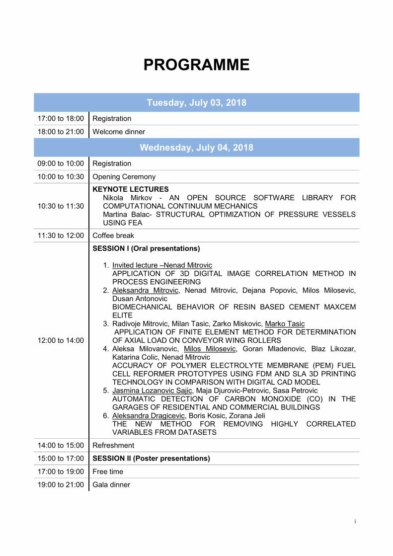
Tuesday, July 03, 2018
17:00 to 18:00 Registration
18:00 to 21:00 Welcome dinner
Wednesday, July 04, 2018
09:00 to 10:00 Registration
10:00 to 10:30 Opening Ceremony
10:30 to 11:30
KEYNOTE LECTURES Nikola Mirkov - AN OPEN SOURCE SOFTWARE LIBRARY FOR COMPUTATIONAL CONTINUUM MECHANICS Martina Balac- STRUCTURAL OPTIMIZATION OF PRESSURE VESSELS USING FEA
11:30 to 12:00 Coffee break
12:00 to 14:00
SESSION I (Oral presentations)
1. Invited lecture –Nenad Mitrovic APPLICATION OF 3D DIGITAL IMAGE CORRELATION METHOD IN PROCESS ENGINEERING
2. Aleksandra Mitrovic, Nenad Mitrovic, Dejana Popovic, Milos Milosevic, Dusan Antonovic BIOMECHANICAL BEHAVIOR OF RESIN BASED CEMENT MAXCEM ELITE
3. Radivoje Mitrovic, Milan Tasic, Zarko Miskovic, Marko Tasic APPLICATION OF FINITE ELEMENT METHOD FOR DETERMINATION OF AXIAL LOAD ON CONVEYOR WING ROLLERS
4. Aleksa Milovanovic, Milos Milosevic, Goran Mladenovic, Blaz Likozar, Katarina Colic, Nenad Mitrovic ACCURACY OF POLYMER ELECTROLYTE MEMBRANE (PEM) FUEL CELL REFORMER PROTOTYPES USING FDM AND SLA 3D PRINTING TECHNOLOGY IN COMPARISON WITH DIGITAL CAD MODEL
5. Jasmina Lozanovic Sajic, Maja Djurovic-Petrovic, Sasa Petrovic AUTOMATIC DETECTION OF CARBON MONOXIDE (CO) IN THE GARAGES OF RESIDENTIAL AND COMMERCIAL BUILDINGS
6. Aleksandra Dragicevic, Boris Kosic, Zorana Jeli THE NEW METHOD FOR REMOVING HIGHLY CORRELATED VARIABLES FROM DATASETS
14:00 to 15:00 Refreshment
15:00 to 17:00 SESSION II (Poster presentations)
17:00 to 19:00 Free time
19:00 to 21:00 Gala dinner

ii
Thursday, July 05, 2018
10:00 to 11:30
SESSION III (Oral presentations)
1. Invited lecture – Sanja Dobrnjac, Mirko Dobrnjac, Jelena Penavin Skundric, Ljubica Vasiljevic, Stevan Blagojevic, Zvjezdana Sandic POSSIBILITY FOR REMOVING PRODUCTS OF THERMAL DEGRADATION OF EDIBLE OIL BY NATURAL ALUMINOSILICATES
2. Invited lecture – Mirko Dobrnjac, Milos Markovic THE SOLAR MEASUREMENT STATION FOR EXAMINATION OF THE THERMAL RECEIVER FOR SOLAR ENERGY
3. Darko Jocic, Velimir Cirovic, Dragan Aleksendric IDENTIFICATION AND RECOGNITION OF VEHICLE ENVIRONMENT USING ARTIFICIAL NEURAL NETWORKS
4. Natasa Kablar COMPUTATIONAL STUDY OF WNT SIGNALING PATHWAY IN ALZHEIMER DISEASE
5. Goran Mladenovic, Marko Milovanovic, Ljubodrag Tanovic, Tim Jones, Milos Pjevic MANUFACTURING AND GEOMETRY MEASUREMENT OF PARTS WITH FREE FORM SURFACES
11:30 to 12:00 Coffee break
12:00 to 14:00 WORKSHOP (INTELLECTUAL PROPERTY)
14:00 to 15:00 Refreshment
15:00 to 16:30
SESSION IV (Oral presentations)
1. Invited lecture – Snezana Kirin INNOVATION MANAGEMENT - LEAN ENTERPRISE
2. Invited lecture – Stefan Culafic NUMERICAL AND EXPERIMENTAL ANALYSIS OF STRENGTH OF STRUCTURAL ELEMENTS IN HYDRO - POWER PLANTS
3. Marta Trninic, DuSan Todorovic, Aleksandar Jovovic, Dragoslava Stojiljkovic, Øyvind Skreiberg, Liang Wang, NebojSa Manic MATHEMATICAL MODELLING AND PERFORMANCE ANALYSIS OF A SMALL-SCALE COMBINED HEAT AND POWER SYSTEM BASED ON BIOMASS WASTE DOWNDRAFT GASIFICATION
4. Nebojsa Manic, Bojan Jankovic, Dragoslava Stojiljkovic, Vladimir Jovanovic, Martina Balac TGA-DSC-MS ANALYSIS OF PYROLYSIS PROCESS OF VARIOUS BIOMASSES WITH ISOCONVERSIONAL (MODEL-FREE) KINETICS
5. Vera Cerovic, Dragan Milkovic, Aleksandar Grbovic, Sasa Radulovic, Jovan Tanaskovic EXPERIMENTAL MEASUREMENTS OF THE STRESSES IN THE LOWER LINK OF THE THREE-POINT HITCH MECHANISM
6. Katarina Colic, Aleksandar Grbovic, Aleksandar Sedmak, Kaled Legweel, UroS Tatic NUMERICAL METHODS IN ASESSMENT OF HIP IMPLANT DESIGN AND INTEGRITY
16:30 to 17:00 Coffee break
17:00 to 18:00 WORKSHOP(EU PROJECTS – NEW PROJECT IDEAS)
18:00 to 21:00 Dinner

iii
Friday, July 06, 2018
10:00 to 10:30 Closing ceremony
From 10:30 Zlatibor excursion

1
ABSTRACTS

2
Mechanical Engineering

CNN TECH 2018 - The Book of Abstracts
J-INTEGRAL IN ELASTO
1Innovation Center of Faculty of Mechanical Engineering, Kraljice
*Corresponding author
Abstract
The elastic-plastic fracture mechanics parameters evaluated in this paper, i.e. Jsensitive to calculation technique used. In other words, differences in their values, obtained by changing finite element techniques such as significant. Application of the finite element method to the elasticwith ESIS recommendations. Thus, the quadrangle eightwhile the crack tip singularity was modelledand mid-side nodes and mid-side nodes. For the static load case, one should differentiate between the material behaviour, which is described as linearly elastic, and the material cannot be neglected. In the former case the linear elastic fracture mechanics (LEFM) applies, while in the latter case, depending on the form of the material plastic flow, mechanics were used. The J-integral is path independent, as shown by its evaluation along six different paths, which is another proof of its correct evaluation. The basic aim of this paper is to contribute to the aintegrity of a cracked combustion chamber, i.e. cylindrical pressure vessel. Toward this end elasticfracture mechanics parameters were evaluated, which could serve as crack driving forces for any cracked structure. As the relevant parameters, the Jchosen and evaluated by the elasticsurface crack was represented as twoof edge cracked plate loaded by remote tensile stress.
Keywords
Finite elements, pressure vessel, elastic
„International Conference of Experimental and
Numerical Investigations and New
Zlatibor, July 0
Mechanical Engineering
INTEGRAL IN ELASTO-PLASTIC FRACTUREEmina S Dzindo1*
Innovation Center of Faculty of Mechanical Engineering, Kraljice Marije 16, 11120 Belgrade 35
Republic of Serbia
Corresponding author e-mail: [email protected]
plastic fracture mechanics parameters evaluated in this paper, i.e. J-integral and CTOD, are not sensitive to calculation technique used. In other words, differences in their values, obtained by changing finite element techniques such as modelling the material behaviour and prescribing the loading, are not
Application of the finite element method to the elastic-plastic fracture mechanics problem was in accordance , the quadrangle eight-nodded isoperimetric finite
modelled by triangular elements with three independent nodes at crack tip side nodes. For the static load case, one should differentiate between the
ch is described as linearly elastic, and the material behaviourcannot be neglected. In the former case the linear elastic fracture mechanics (LEFM) applies, while in the latter case, depending on the form of the material plastic flow, various forms of elastic
integral is path independent, as shown by its evaluation along six different paths, which is another proof of its correct evaluation. The basic aim of this paper is to contribute to the aintegrity of a cracked combustion chamber, i.e. cylindrical pressure vessel. Toward this end elasticfracture mechanics parameters were evaluated, which could serve as crack driving forces for any cracked
relevant parameters, the J-integral and crack tip opening displacement (CTOD) were chosen and evaluated by the elastic-plastic finite element method. The combustion chamber with an axial surface crack was represented as two-dimensional plane strain elastic-plastic finite element model, in a form of edge cracked plate loaded by remote tensile stress.
inite elements, pressure vessel, elastic-plastic fracture, J-integral, CTOD
3
„International Conference of Experimental and
estigations and New Technologies“
Zlatibor, July 04-06, 2018
Mechanical Engineering
IC FRACTURE
Marije 16, 11120 Belgrade 35
integral and CTOD, are not sensitive to calculation technique used. In other words, differences in their values, obtained by changing
and prescribing the loading, are not
plastic fracture mechanics problem was in accordance nodded isoperimetric finite elements were used,
by triangular elements with three independent nodes at crack tip side nodes. For the static load case, one should differentiate between the
behaviour when the plasticity cannot be neglected. In the former case the linear elastic fracture mechanics (LEFM) applies, while in the
various forms of elastic-plastic fracture
integral is path independent, as shown by its evaluation along six different paths, which is another proof of its correct evaluation. The basic aim of this paper is to contribute to the assessment of structural integrity of a cracked combustion chamber, i.e. cylindrical pressure vessel. Toward this end elastic-plastic fracture mechanics parameters were evaluated, which could serve as crack driving forces for any cracked
integral and crack tip opening displacement (CTOD) were plastic finite element method. The combustion chamber with an axial
plastic finite element model, in a form

CNN TECH 2018 - The Book of Abstracts
HEAT AND ELECTRICITY
1
*Corresponding author e
Abstract
In this paper we explain basic principles of biomass energy transformation into heat and electricity. propose technical system that convertswarm the water or other fluid in order to produce heat, or which use steam turbine and generator of electrical energy in order to produce electricity. We give block diagram. Our aim is to develop small technical system that will serve as prototype. We are also interested in batteries development in order to store electricity, or to provide electrical energy directly to grid. This kind of tadditional way of providing electrical energy in homes. This is so additional form of electrical energy can be used any form geothermal, or electricity from generators, accumulators or batteries.
Keywords
Biomass energy, technical system prototype, electrical energy generation, green energy
„International Conference of Experimental and
Numerical Investigations and New
Zlatibor, July 0
Mechanical Engineering
HEAT AND ELECTRICITY PRODUCTION FROM
BIOMASS Natasa A. Kablar1*
1Lola Institute, 11000 Belgrade, Serbia
Corresponding author e-mail: [email protected]
In this paper we explain basic principles of biomass energy transformation into heat and electricity. system that converts biomass energy through process of combustion in furnace in order to
warm the water or other fluid in order to produce heat, or which use steam turbine and generator of electrical ity. We give block diagram. Our aim is to develop small technical system
that will serve as prototype. We are also interested in batteries development in order to store electricity, or to provide electrical energy directly to grid. This kind of technical system can be used as additional way of providing electrical energy in homes. This is so called hybrid energy concept,
form of electrical energy can be used any form of green energies - wind, solar, water, biomass or or electricity from generators, accumulators or batteries.
energy, technical system prototype, electrical energy generation, green energy
4
„International Conference of Experimental and
estigations and New Technologies“
Zlatibor, July 04-06, 2018
Mechanical Engineering
PRODUCTION FROM
In this paper we explain basic principles of biomass energy transformation into heat and electricity. We biomass energy through process of combustion in furnace in order to
warm the water or other fluid in order to produce heat, or which use steam turbine and generator of electrical ity. We give block diagram. Our aim is to develop small technical system
that will serve as prototype. We are also interested in batteries development in order to store generated echnical system can be used as hybrid energy concept, whereas
wind, solar, water, biomass or
energy, technical system prototype, electrical energy generation, green energy

CNN TECH 2018 - The Book of Abstracts
AUTOMATIC DETECTION
IN THE GARAGES OF RE
COMMERCIAL BUILDINGJasmina Lozanovi
1University of Belgrade, Faculty of Mechanical Engineering, Department of Information Technologies, 11000
2PhD candidate on Mechanical Engineering Faculty University of Ni
*Corresponding author
Abstract
This paper presents the method of automatic detection of carbon monoxide (CO) concentration. The exhaust gases of the engine contain carbon monoxide toxic gas. Therefore, regulations stipulate that every closed garage must have an automatic detection system for carbon monoxide. It has no It is cytotoxic for living beings, as it belongs to the group of chemical (about 50 percent of poisoning in the world is from this gas).The exhaust gases of internal combustion engines are one of the biggest atmospheric pollutants with this gas, then exhaust gases that occur during the proand in the process of production in oil refineries and the chemical industry.The automatic detection system can detect at the same time and several different gases, with an adequate detector. Thanks to the new technology in the design of the central and gas sensors, the system has a high sensitivity and fast response. When the gas concentration reaches or exceeds the set alarm levels, the control panel immediately illuminates and activates the other immediately and sounds.
Keywords
Control system, Automatic detection system, carbon monoxide.
Acknowledgement
This work is a contribution to the Ministry of Education, Science and Technological Development, RepuSerbia funded project TR35013.
„International Conference of Experimental and
Numerical Investigations and New
Zlatibor, July 0
Mechanical Engineering
AUTOMATIC DETECTION OF CARBON MONOXIDE (
IN THE GARAGES OF RESIDENTIAL AND
COMMERCIAL BUILDINGS Lozanovic Sajic1*, Maja Djurovic-Petrovic1, Sasa Petrovi
University of Belgrade, Faculty of Mechanical Engineering, Department of Information Technologies, 11000 Belgrade, Serbia
PhD candidate on Mechanical Engineering Faculty University of Nis, Serbia
*Corresponding author e-mail: [email protected]
This paper presents the method of automatic detection of carbon monoxide (CO) concentration. The exhaust on monoxide toxic gas. Therefore, regulations stipulate that every closed
garage must have an automatic detection system for carbon monoxide. It has no colourIt is cytotoxic for living beings, as it belongs to the group of chemical buffers and the biggest air pollutants (about 50 percent of poisoning in the world is from this gas). The exhaust gases of internal combustion engines are one of the biggest atmospheric pollutants with this gas, then exhaust gases that occur during the production of iron, coal combustion in thermal power plants and in the process of production in oil refineries and the chemical industry. The automatic detection system can detect at the same time and several different gases, with an adequate
to the new technology in the design of the central and gas sensors, the system has a high sensitivity and fast response. When the gas concentration reaches or exceeds the set alarm levels, the control panel immediately illuminates and activates the other outputs for the desired executive functions
Control system, Automatic detection system, carbon monoxide.
This work is a contribution to the Ministry of Education, Science and Technological Development, Repu
5
„International Conference of Experimental and
estigations and New Technologies“
Zlatibor, July 04-06, 2018
Mechanical Engineering
OF CARBON MONOXIDE (CO)
SIDENTIAL AND
a Petrovic2
University of Belgrade, Faculty of Mechanical Engineering, Department of Information Technologies, 11000
s, Serbia
This paper presents the method of automatic detection of carbon monoxide (CO) concentration. The exhaust on monoxide toxic gas. Therefore, regulations stipulate that every closed
colour, taste, smell and air. buffers and the biggest air pollutants
The exhaust gases of internal combustion engines are one of the biggest atmospheric pollutants with this duction of iron, coal combustion in thermal power plants
The automatic detection system can detect at the same time and several different gases, with an adequate to the new technology in the design of the central and gas sensors, the system has a high
sensitivity and fast response. When the gas concentration reaches or exceeds the set alarm levels, the outputs for the desired executive functions
This work is a contribution to the Ministry of Education, Science and Technological Development, Republic of

CNN TECH 2018 - The Book of Abstracts
STATIC STRENGTH ANAL
STRUCTURE OF BIOMASS
HYDROSTATIC PRESSUREJovan D. Tanaskovic
1University of Belgrade, Faculty of Mechanical Engineering, Department of Rai
2University of Belgrade, Faculty of Mechanical Engineering, Department of Process Engineering and Environment Protection, 11000 Belgrade, Serbia
*Corresponding author e
Abstract
Subject of this paper is numerical analysis of the steel structure of biomass reservoir under hydrostatic pressure as well as additional loads. Reservoir was made from steel grade S235 and presents disassembly construction which contains eight walls of height of 5.5 meters placed on the floor in diameter of 10 meters. The floor is supported on eight legs along the scope and on the four center legs. Static strength analysis was performed by finite element method using 3D modanalysed: a) hydrostatic pressure obtained by water to the height of 5 meters, b) hydrostatic pressure and snow force on the upper flange of 5.9 kN and c) hydrostatic pressure and biogas pressure on under 8 mbar. Numerical results showed that the structure is not correctly defined. Maximal values of stresses are much higher than allowed for the steel S235, especially in the floor construction and on the joins between the walls and the floor. Reconstruction of the reservoir was suggested. The floor is reinforced by the under frame made from tubes of rectangle cross section and with additional supports in the central zone. These modifications gave lower values of the stresses. However, for use of fulincrease thickness of steel cover of the floor and the walls on the height of 1 meter from the floor. Without any changes of the steel construction, producer decided to use reservoir with capacity of 1/5 of full (1m height of water) and moved prototype to farm where assembly of them started.
Keywords
Biomass, Finite Element Method, Hydrostatic Pressure, Static Strength Analysis, Biogas
Acknowledgement
The research work is funded by the Ministry of Education, Science aRepublic of Serbia, Projects TR35045 and TR35031.
„International Conference of Experimental and
Numerical Investigations and New
Zlatibor, July 0
Mechanical Engineering
STATIC STRENGTH ANALYSES OF THE STEEL
STRUCTURE OF BIOMASS RESERVOIR UNDER
HYDROSTATIC PRESSURE Jovan D. Tanaskovic1*, Martina M. Balac2
University of Belgrade, Faculty of Mechanical Engineering, Department of Rail Vehicles, 11000 Belgrade, Serbia
University of Belgrade, Faculty of Mechanical Engineering, Department of Process Engineering and Environment Protection, 11000 Belgrade, Serbia
Corresponding author e-mail: [email protected]
Subject of this paper is numerical analysis of the steel structure of biomass reservoir under hydrostatic pressure as well as additional loads. Reservoir was made from steel grade S235 and presents disassembly
which contains eight walls of height of 5.5 meters placed on the floor in diameter of 10 meters. The floor is supported on eight legs along the scope and on the four center legs. Static strength analysis was performed by finite element method using 3D model obtained by the producer. Three load cases were
: a) hydrostatic pressure obtained by water to the height of 5 meters, b) hydrostatic pressure and snow force on the upper flange of 5.9 kN and c) hydrostatic pressure and biogas pressure on under 8 mbar. Numerical results showed that the structure is not correctly defined. Maximal values of stresses are much higher than allowed for the steel S235, especially in the floor construction and on the joins between the
struction of the reservoir was suggested. The floor is reinforced by the under frame made from tubes of rectangle cross section and with additional supports in the central zone. These modifications gave lower values of the stresses. However, for use of full capacity of reservoir is necessary to increase thickness of steel cover of the floor and the walls on the height of 1 meter from the floor. Without any changes of the steel construction, producer decided to use reservoir with capacity of 1/5 of full (1m height of water) and moved prototype to farm where assembly of them started.
Biomass, Finite Element Method, Hydrostatic Pressure, Static Strength Analysis, Biogas
The research work is funded by the Ministry of Education, Science and Technological Development of Republic of Serbia, Projects TR35045 and TR35031.
6
„International Conference of Experimental and
estigations and New Technologies“
Zlatibor, July 04-06, 2018
Mechanical Engineering
YSES OF THE STEEL
RESERVOIR UNDER
l Vehicles, 11000 Belgrade,
University of Belgrade, Faculty of Mechanical Engineering, Department of Process Engineering and
Subject of this paper is numerical analysis of the steel structure of biomass reservoir under hydrostatic pressure as well as additional loads. Reservoir was made from steel grade S235 and presents disassembly
which contains eight walls of height of 5.5 meters placed on the floor in diameter of 10 meters. The floor is supported on eight legs along the scope and on the four center legs. Static strength analysis was
el obtained by the producer. Three load cases were : a) hydrostatic pressure obtained by water to the height of 5 meters, b) hydrostatic pressure and
snow force on the upper flange of 5.9 kN and c) hydrostatic pressure and biogas pressure on under flange of 8 mbar. Numerical results showed that the structure is not correctly defined. Maximal values of stresses are much higher than allowed for the steel S235, especially in the floor construction and on the joins between the
struction of the reservoir was suggested. The floor is reinforced by the under frame made from tubes of rectangle cross section and with additional supports in the central zone. These
l capacity of reservoir is necessary to increase thickness of steel cover of the floor and the walls on the height of 1 meter from the floor. Without any changes of the steel construction, producer decided to use reservoir with capacity of 1/5 of full (1m
Biomass, Finite Element Method, Hydrostatic Pressure, Static Strength Analysis, Biogas
nd Technological Development of

CNN TECH 2018 - The Book of Abstracts
Invited lecture
NUMERICAL AND EXPERI
STRENGTH OF STRUCTUR
1University of Montenegro, Faculty of Mechanical Engine
*Corresponding author e
Abstract
In this paper is presented the summary of investigation about the numerical and experimental analysistrength of structural elements in Hydro experimental part. In the numerical part of investigation FEM will be applied for to obtain the values of stresses and strains in the specified spots andof the structural elements. In the experimental part of investigation, experiments will be conducted in both laboratory and exploitation conditions, to confirm the values obtained through tbased on the three significant directions. These are: 1) values of stress and strain in the specified parts of the pipeline 2) values of vibrations and dynamic loads, in the turbine rotor, and shaft,3) dilatations in the pipeline caused by temperature changes in the pipeline environment.
Keywords
FEM, stresses, strains, Hydro - power plants, experimental analysis
„International Conference of Experimental and
Numerical Investigations and New
Zlatibor, July 0
Mechanical Engineering
NUMERICAL AND EXPERIMENTAL ANALYSIS OF
STRENGTH OF STRUCTURAL ELEMENTS IN HYDRO
POWER PLANTS Stefan G. Culafic1*,
University of Montenegro, Faculty of Mechanical Engineering, Department of Applied Mechanics, 20000 Podgorica, Montenegro
Corresponding author e-mail: [email protected]
presented the summary of investigation about the numerical and experimental analysistrength of structural elements in Hydro - power plants. The investigation contains numerical and experimental part. In the numerical part of investigation FEM will be applied for to obtain the values of stresses and strains in the specified spots and characteristic strips which will be recognized as critical places of the structural elements. In the experimental part of investigation, experiments will be conducted in both laboratory and exploitation conditions, to confirm the values obtained through the FEM. Investigation will be based on the three significant directions. These are: 1) values of stress and strain in the specified parts of the pipeline 2) values of vibrations and dynamic loads, in the turbine rotor, and shaft,
peline caused by temperature changes in the pipeline environment.
power plants, experimental analysis
7
„International Conference of Experimental and
estigations and New Technologies“
Zlatibor, July 04-06, 2018
Mechanical Engineering
MENTAL ANALYSIS OF
AL ELEMENTS IN HYDRO -
ering, Department of Applied Mechanics, 20000
presented the summary of investigation about the numerical and experimental analysis of power plants. The investigation contains numerical and
experimental part. In the numerical part of investigation FEM will be applied for to obtain the values of characteristic strips which will be recognized as critical places
of the structural elements. In the experimental part of investigation, experiments will be conducted in both he FEM. Investigation will be
peline caused by temperature changes in the pipeline environment.

CNN TECH 2018 - The Book of Abstracts
Invited lecture
THE SOLAR MEASUREMEN
EXAMINATION OF THE T
Mirko Dobrnjac1University of Banjaluka, Faculty of Mechanical Engineering, 78000 Banjaluka, Bosnia and Herzegovina
*Corresponding author e
Abstract
The use of renewable energy sources is becoming increasingly apparent, including solar energy, which is directly or indirectly the only source of life on Earth. Monitoring of the manifestation of solar radiation and the exploitation of this type of energy predominantly imposes the need trelated to radiation itself, as well as radiation receivers and other devices of the system. Thermal receivers with liquid as a solar energy transmitter have now become consumer goods with a large number of manufacturers. Their examination is important with several aspects; from scientific research, for their further research and development, but also from the perspective of consumers, as they obtain reliable information on the quality of solar collectors, on the basis of whpaper is to examine one design of the measurement station for testing solar collectors with all components, as well as presenting possible test methods according to the standard SRPS M.F5.050.a solar measuring station where the described measuring devices are used for measuring the parameters in the operation of the solar thermal panel and give examples of the presentation of the processed results.
Keywords
Heat transfer, solar collector, measurement station, energy efficiency, solar energy
„International Conference of Experimental and
Numerical Investigations and New
Zlatibor, July 0
Mechanical Engineering
THE SOLAR MEASUREMENT STATION FOR
EXAMINATION OF THE THERMAL RECEIVER FOR
SOLAR ENERGY Mirko Dobrnjac1*, Milos Markovic1,
University of Banjaluka, Faculty of Mechanical Engineering, 78000 Banjaluka, Bosnia and Herzegovina
Corresponding author e-mail: [email protected]
ces is becoming increasingly apparent, including solar energy, which is directly or indirectly the only source of life on Earth. Monitoring of the manifestation of solar radiation and the exploitation of this type of energy predominantly imposes the need to measure a number of parameters related to radiation itself, as well as radiation receivers and other devices of the system. Thermal receivers with liquid as a solar energy transmitter have now become consumer goods with a large number of
heir examination is important with several aspects; from scientific research, for their further research and development, but also from the perspective of consumers, as they obtain reliable information on the quality of solar collectors, on the basis of which they choose the most optimal solution. The aim of the
to examine one design of the measurement station for testing solar collectors with all components, as well as presenting possible test methods according to the standard SRPS M.F5.050.a solar measuring station where the described measuring devices are used for measuring the parameters in the operation of the solar thermal panel and give examples of the presentation of the processed results.
llector, measurement station, energy efficiency, solar energy
8
„International Conference of Experimental and
estigations and New Technologies“
Zlatibor, July 04-06, 2018
Mechanical Engineering
T STATION FOR
HERMAL RECEIVER FOR
University of Banjaluka, Faculty of Mechanical Engineering, 78000 Banjaluka, Bosnia and Herzegovina
ces is becoming increasingly apparent, including solar energy, which is directly or indirectly the only source of life on Earth. Monitoring of the manifestation of solar radiation and the
o measure a number of parameters related to radiation itself, as well as radiation receivers and other devices of the system. Thermal receivers with liquid as a solar energy transmitter have now become consumer goods with a large number of
heir examination is important with several aspects; from scientific research, for their further research and development, but also from the perspective of consumers, as they obtain reliable information
ich they choose the most optimal solution. The aim of the to examine one design of the measurement station for testing solar collectors with all components,
as well as presenting possible test methods according to the standard SRPS M.F5.050. The paper presents a solar measuring station where the described measuring devices are used for measuring the parameters in the operation of the solar thermal panel and give examples of the presentation of the processed results.
CNN TECH 2018 - The Book of Abstracts
COMPARISON BETWEEN D
PROCEDURES OF LOADS
DILATATION IN PIPELIMilan Travica
1University of Belgrade, Innovation Center of Faculty of Mechanical Engineering,2University of Belgrade, Faculty of Mechanical Engineering, Department of Process technique and
environmental protection, 11000 Belgrade, Serbia
*Corresponding author e
Abstract
The problem of loads caused by the temperature dilatations in pipes and its effect on strain and stress state of the entire pipeline is common problem in engineering practice. This paper dcalculation of loads that can occur in the pipeline caused by temperature differences. The study presented in the paper analysed the L shaped pipeline configuration with an operating temperature at 200material P235GH, angle between legs of the L shaped pipeline is 90pressure is 10bar (absolute pressure). The calculation was presented according to standards EN 13480and AD 2000 and Russian method commonly used in engineering pradifferent engineering approaches for solving the same type of the problem, so the specific differences were presented in the paper. All the results are presented in unified tables for easier comparison and analysis. It can be conducted that all three presented methods showed similar results and choosing the most suitable one for the practical application is mainly determined by the type of the result needed for the specific application.
Keywords
Temperature dilatation; L shaped pipeline configuration; standards, EN13480
„International Conference of Experimental and
Numerical Investigations and New
Zlatibor, July 0
Mechanical Engineering
COMPARISON BETWEEN DIFFERENT CALCULATION
PROCEDURES OF LOADS CAUSED BY TEMPERATUR
DILATATION IN PIPELINES Milan Travica1*, Nenad Mitrovic2, Aleksandar Petrovic2
vation Center of Faculty of Mechanical Engineering, 11000 Belgrade, Serbia
University of Belgrade, Faculty of Mechanical Engineering, Department of Process technique and environmental protection, 11000 Belgrade, Serbia
Corresponding author e-mail: [email protected]
The problem of loads caused by the temperature dilatations in pipes and its effect on strain and stress state of the entire pipeline is common problem in engineering practice. This paper describes three calculation of loads that can occur in the pipeline caused by temperature differences. The study presented in the paper analysed the L shaped pipeline configuration with an operating temperature at 200
, angle between legs of the L shaped pipeline is 90⁰, pipe dimension DN 300 and operating pressure is 10bar (absolute pressure). The calculation was presented according to standards EN 13480and AD 2000 and Russian method commonly used in engineering practice. The three methods have different engineering approaches for solving the same type of the problem, so the specific differences were presented in the paper. All the results are presented in unified tables for easier comparison and analysis. It
presented methods showed similar results and choosing the most suitable one for the practical application is mainly determined by the type of the result needed for the specific
pipeline configuration; standards, EN13480-3; AD 2000;
9
„International Conference of Experimental and
estigations and New Technologies“
Zlatibor, July 04-06, 2018
Mechanical Engineering
IFFERENT CALCULATION
CAUSED BY TEMPERATURE
11000 Belgrade, Serbia
University of Belgrade, Faculty of Mechanical Engineering, Department of Process technique and
The problem of loads caused by the temperature dilatations in pipes and its effect on strain and stress state escribes three methods for
calculation of loads that can occur in the pipeline caused by temperature differences. The study presented in the paper analysed the L shaped pipeline configuration with an operating temperature at 200
oC, pipeline
, pipe dimension DN 300 and operating pressure is 10bar (absolute pressure). The calculation was presented according to standards EN 13480-3
ctice. The three methods have different engineering approaches for solving the same type of the problem, so the specific differences were presented in the paper. All the results are presented in unified tables for easier comparison and analysis. It
presented methods showed similar results and choosing the most suitable one for the practical application is mainly determined by the type of the result needed for the specific
3; AD 2000; Russian method
CNN TECH 2018 - The Book of Abstracts
Invited lecture
INNOVATION MANAGEMEN
1University of Belgrade, Innovation center of Faculty of Serbia,
*Corresponding author e
Abstract
Management is highly important function in today’s dynamic business environment. Many historical milestones have shaped management process, scientific management, serial production at Ford's factories, the human relations movement, management science, reengineering, flexibility, computer age, timeand environmental issues. Globalization enabled creation of global supply chains, creation of new worldclass organizations and unions and brought great competition. International trade barriers have fallen. And new trade agreements have created. The aim of this paper is to present lean approach as a modern production system developed by Toyota Motor Corporation in order to ensure best quality, lowest prices and shorter preparation periods by eliminating unnecessary costs. Toyota managers shiindividual machines and their utilization, to the flow of the product through the total process. They concluded that by right-sizing machines for the real volume needed, introducing pull production system, machines to ensure quality, lining the machines up in process section, and having each process step notify the previous step of its current needs for materials.
Keywords
Innovation management; Lean approach; modern production system
„International Conference of Experimental and
Numerical Investigations and New
Zlatibor, July 0
Mechanical Engineering
INNOVATION MANAGEMENT- LEAN ENTERPRISE1Snezana Kirin
center of Faculty of Mechanical Engineering, KraljiceSerbia, ORCID: 0000-0002-2176-3969
Corresponding author e-mail: [email protected]
Management is highly important function in today’s dynamic business environment. Many historical milestones have shaped management process. Some of these are the Industrial Revolution, Bessemer process, scientific management, serial production at Ford's factories, the human relations movement, management science, reengineering, flexibility, computer age, time-based competition, globaland environmental issues. Globalization enabled creation of global supply chains, creation of new worldclass organizations and unions and brought great competition. International trade barriers have fallen. And
ted. The aim of this paper is to present lean approach as a modern production system developed by Toyota Motor Corporation in order to ensure best quality, lowest prices and shorter preparation periods by eliminating unnecessary costs. Toyota managers shifted the focus of the manufacturing engineer from individual machines and their utilization, to the flow of the product through the total process. They concluded
sizing machines for the real volume needed, introducing pull production system, machines to ensure quality, lining the machines up in process section, and having each process step notify the previous step of its current needs for materials.
Innovation management; Lean approach; modern production system
10
„International Conference of Experimental and
estigations and New Technologies“
Zlatibor, July 04-06, 2018
Mechanical Engineering
LEAN ENTERPRISE
, Kraljice Marije 16, Belgrade,
Management is highly important function in today’s dynamic business environment. Many historical process. Some of these are the Industrial Revolution, Bessemer
process, scientific management, serial production at Ford's factories, the human relations movement, based competition, global marketplace,
and environmental issues. Globalization enabled creation of global supply chains, creation of new world-class organizations and unions and brought great competition. International trade barriers have fallen. And
The aim of this paper is to present lean approach as a modern production system developed by Toyota Motor Corporation in order to ensure best quality, lowest prices and shorter preparation periods by
fted the focus of the manufacturing engineer from individual machines and their utilization, to the flow of the product through the total process. They concluded
sizing machines for the real volume needed, introducing pull production system, self-monitoring machines to ensure quality, lining the machines up in process section, and having each process step notify

CNN TECH 2018 - The Book of Abstracts
IDENTIFICATION AND RECO
ENVIRONMENT USING AR
Darko Jocic1University of Belgrade, Innovation center of Faculty of Mechanical Engineering, Kraljice
*Corresponding author e
Abstract
Object detection using deep learning over the years became one of the most popular implementation in autonomous systems. Autonomous vehicle requiidentification and recognition of surrounding objects in real traffic environments to achieve decent detection results. In this paper, special type of Artificial Neural Network (ANN) named Convolutional Neural Network (CNN) was used for identification and recognition of surrounding objects in real traffic. The new model based on CNN was trained and developed to be able to identify and recognize 4 different classes of objects: cars, traffic lights, persons and bicycles. The deand recognizing on the test set.
Keywords
Artificial Neural Networks, Convolutional Neural Network, Object Detection,
„International Conference of Experimental and
Numerical Investigations and New
Zlatibor, July 0
Mechanical Engineering
NTIFICATION AND RECOGNITION OF VEHICLE
ENVIRONMENT USING ARTIFICIAL NEURAL
NETWORKS Darko Jocic1, Velimir Cirovic1, Dragan Aleksendric1
University of Belgrade, Innovation center of Faculty of Mechanical Engineering, KraljiceSerbia
orresponding author e-mail: [email protected]
Object detection using deep learning over the years became one of the most popular implementation in autonomous systems. Autonomous vehicle requires very reliable and accurate identification and recognition of surrounding objects in real traffic environments to achieve decent detection results. In this paper, special type of Artificial Neural Network (ANN) named Convolutional Neural Network
as used for identification and recognition of surrounding objects in real traffic. The new model based was trained and developed to be able to identify and recognize 4 different classes of objects: cars,
persons and bicycles. The developed model has shown 94.6% accuracy of object identification
Artificial Neural Networks, Convolutional Neural Network, Object Detection, Vehicles Environment
11
„International Conference of Experimental and
estigations and New Technologies“
Zlatibor, July 04-06, 2018
Mechanical Engineering
GNITION OF VEHICLE
TIFICIAL NEURAL
University of Belgrade, Innovation center of Faculty of Mechanical Engineering, Kraljice Marije 16, Belgrade,
Object detection using deep learning over the years became one of the most popular methods for res very reliable and accurate
identification and recognition of surrounding objects in real traffic environments to achieve decent detection results. In this paper, special type of Artificial Neural Network (ANN) named Convolutional Neural Network
as used for identification and recognition of surrounding objects in real traffic. The new model based was trained and developed to be able to identify and recognize 4 different classes of objects: cars,
veloped model has shown 94.6% accuracy of object identification
Vehicles Environment

CNN TECH 2018 - The Book of Abstracts
DESIGN STUDY OF
Boris Kosic1, Misa Stojicevic1, Zorana Jeli1University of Belgrade, Faculty of Mechanical Engineering, Department of Information Technologies, 11000
*Corresponding author
Abstract
Different geometry of metameterials has ability to withstand a certain level of deformation, and is used to replace joints in certain assemblies of technical systems. Using this characteristimovements could be accomplished with deformation of technical system structures.This paper cover examination on two different kind of geometry structure of metamaterials, regular and irregular octagon, and the influence of technical systems. A larger number of simulations have been conducted by changing internal structure and orientation of metamaterials. Also, those metametarials have been used on some of the model of Further, the pliers models were simulated, and results were compared with the results from previous simulations. For each simulation the results were presented as stresses and displacements with the same load, but different direction of force. been used for simulation, design of the 3D models and whole study. using design study, define the level of deformation which structures can withstand, andgave the ideas for methodology of the concept for pre
Keywords:
3D model, metamaterial, design study, Solid
Acknowledgement
This work was financially supported by the Ministry of ScienceRepublic of Serbia through project No. TR 35011.
„International Conference of Experimental and
Numerical Investigations and New
Zlatibor, July 0
Mechanical Engineering
DESIGN STUDY OF THE DIFERENT METAMATERIA
SHAPES , Zorana Jeli1, Branislav Pokonstantinovic1, Aleksandra Dragicevic
University of Belgrade, Faculty of Mechanical Engineering, Department of Information Technologies, 11000 Belgrade, Serbia
*Corresponding author e-mail: [email protected]
Different geometry of metameterials has ability to withstand a certain level of deformation, and is used to replace joints in certain assemblies of technical systems. Using this characteristimovements could be accomplished with deformation of technical system structures.
paper cover examination on two different kind of geometry structure of metamaterials, regular and the influence of their geometrical structures, as a new concepts for formation of
A larger number of simulations have been conducted by changing internal structure and orientation of metamaterials. Also, those metametarials have been used on some of the model of
, the pliers models were simulated, and results were compared with the results from previous For each simulation the results were presented as stresses and displacements with the same
load, but different direction of force. SOLIDWORKS 2016, as a powerful tool for this kind of analysis, had been used for simulation, design of the 3D models and whole study. The results obtained from simulations, using design study, define the level of deformation which structures can withstand, andgave the ideas for methodology of the concept for preparing geometry of metametrials
3D model, metamaterial, design study, Solid Works, simulation
This work was financially supported by the Ministry of Science and Technological Development of the Republic of Serbia through project No. TR 35011.
12
„International Conference of Experimental and
estigations and New Technologies“
Zlatibor, July 04-06, 2018
Mechanical Engineering
DIFERENT METAMATERIAL
, Aleksandra Dragicevic1
University of Belgrade, Faculty of Mechanical Engineering, Department of Information Technologies, 11000
Different geometry of metameterials has ability to withstand a certain level of deformation, and is used to replace joints in certain assemblies of technical systems. Using this characteristic of metametrials, all
paper cover examination on two different kind of geometry structure of metamaterials, regular and
as a new concepts for formation of A larger number of simulations have been conducted by changing internal structure and
orientation of metamaterials. Also, those metametarials have been used on some of the model of pliers. , the pliers models were simulated, and results were compared with the results from previous
For each simulation the results were presented as stresses and displacements with the same DWORKS 2016, as a powerful tool for this kind of analysis, had
The results obtained from simulations, using design study, define the level of deformation which structures can withstand, and therewithal, they
paring geometry of metametrials.
and Technological Development of the

CNN TECH 2018 - The Book of Abstracts
THE NEW METHOD FOR R
CORRELATED VARIABLESAleksandra Dragicevic
1University of Belgrade, Faculty of Mechanica
*Corresponding author e
Abstract
Reducing of the data dimensionality is necessary and required for optimal model performance in machine learning. Two different approaches, frequently used in practice to solve this problem, were considered with the aim to build the new one. The basic idea of the first approach is to reduce dimensionality by removing highly correlated variables which implies thatphenomenon that has been observed. It is done by removing all variables with high average correlation. In this way, variables are removed regardless to its significance to model accuracy, and as a reaccuracy can noticeably drop. The second approach implies necessary quantification of variable impact on model outcome and to sort them according to these values for the better understanding of the data, relationship between variables and the model outcome. By using this approach, variables with lowest importance are removed from the data set, and can lead to an increasing in the performance and accuracy of the final model.In the datasets with the highly correlated variables (e.g. sets of spectrvariables can be with the highest average correlation, and after removing those variables the accuracy of the model can be significantly reduced. Based on the previous facts, the new method that uses the most important variables with lowest correlation is proposed, as a combination of the previous two approaches. The main idea of this approach is to notably reduce dataset dimensionality using the variables that have small correlation and where the accuracy remains high.
Keywords
Machine learning, highly correlated data, variable importance, data dimensionality
„International Conference of Experimental and
Numerical Investigations and New
Zlatibor, July 0
Mechanical Engineering
THE NEW METHOD FOR REMOVING HIGHLY
CORRELATED VARIABLES FROM DATASETSAleksandra Dragicevic1, Boris Kosic1, Zorana Jeli1
University of Belgrade, Faculty of Mechanical Engineering, 11000 Belgrade, Serbia
*Corresponding author e-mail: [email protected]
Reducing of the data dimensionality is necessary and required for optimal model performance in machine ing. Two different approaches, frequently used in practice to solve this problem, were considered with
the aim to build the new one. The basic idea of the first approach is to reduce dimensionality by removing highly correlated variables which implies that multiple variables measure the same characteristic of a phenomenon that has been observed. It is done by removing all variables with high average correlation. In this way, variables are removed regardless to its significance to model accuracy, and as a re
The second approach implies necessary quantification of variable impact on model outcome and to sort them according to these values for the better understanding of the data, relationship between variables and the
del outcome. By using this approach, variables with lowest importance are removed from the data set, and can lead to an increasing in the performance and accuracy of the final model. In the datasets with the highly correlated variables (e.g. sets of spectroscopy data), the most important variables can be with the highest average correlation, and after removing those variables the accuracy of the model can be significantly reduced. Based on the previous facts, the new method that uses the most
ables with lowest correlation is proposed, as a combination of the previous two approaches. The main idea of this approach is to notably reduce dataset dimensionality using the variables that have small correlation and where the accuracy remains high.
Machine learning, highly correlated data, variable importance, data dimensionality
13
„International Conference of Experimental and
estigations and New Technologies“
Zlatibor, July 04-06, 2018
Mechanical Engineering
EMOVING HIGHLY
FROM DATASETS
l Engineering, 11000 Belgrade, Serbia
Reducing of the data dimensionality is necessary and required for optimal model performance in machine ing. Two different approaches, frequently used in practice to solve this problem, were considered with
the aim to build the new one. The basic idea of the first approach is to reduce dimensionality by removing multiple variables measure the same characteristic of a
phenomenon that has been observed. It is done by removing all variables with high average correlation. In this way, variables are removed regardless to its significance to model accuracy, and as a result model
The second approach implies necessary quantification of variable impact on model outcome and to sort them according to these values for the better understanding of the data, relationship between variables and the
del outcome. By using this approach, variables with lowest importance are removed from the data set,
oscopy data), the most important variables can be with the highest average correlation, and after removing those variables the accuracy of the model can be significantly reduced. Based on the previous facts, the new method that uses the most
ables with lowest correlation is proposed, as a combination of the previous two approaches. The main idea of this approach is to notably reduce dataset dimensionality using the variables that have

14
Materials Science
CNN TECH 2018 - The Book of Abstracts
ANALYSING SAMPLES AN
Ivan Tanasic
1 University of Belgrade, Faculty for Dental Medici
*Corresponding author e
Abstract
In vitro experiments include proper materials whether human’s or humans’ substituents to avoid invasclinical procedures. In such cases, researchers can use blood, urine or some other stuff but try to close in vitro conditions to in vivo-physiological conditions as much as possible. Following study intended to show examples of the samples and specimenconsideration. In experimental investigation, specimen is considered as an individual issue that represents a class while sample is a part of anything taken or presented for inspection, or shown quality of the whole. The aim of this report was to represent differences between sample and specimen in dentistry research and to show the possibilities of biomechanical investigation of these materials used for in vitro setup. In dental biomechanics, cadaveric teeth and bone, bone substituents artificial membrane, strips/bands, saliva and replacements made for various indications can be used for the purpose of biomechanical analysis. Determination and measuring of strain in these biomatin the interpretation of the results presented in this biomedical report. Differences were shown in the methodological approach involved preparation of specimens/samples and loading conditions. Findings provide that all of these tissues and artificial organs can serve for investigations in dental biomechanics if adequate conditions are conducted. Nevertheless, human cadaveric tissues were found to be the best choice when considered achieving of physiological conditions.
Keywords
Biomaterials, dental samples, biomechanical analysis, cadaveric specimen, artificial organs and tissues
„International Conference of Experimental and
Numerical Investigations and New
Zlatibor, July 0
Materials Science
ANALYSING SAMPLES AND SPECIMENS IN DENTA
BIOMECHANICS Ivan Tanasic1*, Ljiljana Tihacek Sojic1
1 University of Belgrade, Faculty for Dental Medicine, Depatment for Prosthodontics, 11000 Belgrade
*Corresponding author e-mail: [email protected]
In vitro experiments include proper materials whether human’s or humans’ substituents to avoid invasclinical procedures. In such cases, researchers can use blood, urine or some other stuff but try to close in
physiological conditions as much as possible. Following study intended to show examples of the samples and specimens application in dentistry research field with biomechanical
In experimental investigation, specimen is considered as an individual issue that represents a class while sample is a part of anything taken or presented for inspection, or shown
The aim of this report was to represent differences between sample and specimen in dentistry research and to show the possibilities of biomechanical investigation of these materials used for in
l biomechanics, cadaveric teeth and bone, bone substituents artificial membrane, strips/bands, saliva and replacements made for various indications can be used for the purpose of biomechanical analysis. Determination and measuring of strain in these biomaterials was the main criterion in the interpretation of the results presented in this biomedical report. Differences were shown in the methodological approach involved preparation of specimens/samples and loading conditions. Findings
se tissues and artificial organs can serve for investigations in dental biomechanics if adequate conditions are conducted. Nevertheless, human cadaveric tissues were found to be the best choice when considered achieving of physiological conditions.
Biomaterials, dental samples, biomechanical analysis, cadaveric specimen, artificial organs and tissues
15
„International Conference of Experimental and
estigations and New Technologies“
Zlatibor, July 04-06, 2018
Materials Science
D SPECIMENS IN DENTAL
ne, Depatment for Prosthodontics, 11000 Belgrade
In vitro experiments include proper materials whether human’s or humans’ substituents to avoid invasive clinical procedures. In such cases, researchers can use blood, urine or some other stuff but try to close in
physiological conditions as much as possible. Following study intended to show s application in dentistry research field with biomechanical
In experimental investigation, specimen is considered as an individual issue that represents a class while sample is a part of anything taken or presented for inspection, or shown as evidence of the
The aim of this report was to represent differences between sample and specimen in dentistry research and to show the possibilities of biomechanical investigation of these materials used for in
l biomechanics, cadaveric teeth and bone, bone substituents artificial membrane, strips/bands, saliva and replacements made for various indications can be used for the purpose of
erials was the main criterion in the interpretation of the results presented in this biomedical report. Differences were shown in the methodological approach involved preparation of specimens/samples and loading conditions. Findings
se tissues and artificial organs can serve for investigations in dental biomechanics if adequate conditions are conducted. Nevertheless, human cadaveric tissues were found to be the best
Biomaterials, dental samples, biomechanical analysis, cadaveric specimen, artificial organs and tissues
CNN TECH 2018 - The Book of Abstracts
TGA AND DTA ANALYSIS
BASED ON POLY (HYDRO
Aleksandra D. Mitrovic1*, Aleksandra
*1University of Belgrade, Faculty of Technology and Metallurgy, Belgrade, Serbia2University of Belgrade, Faculty of Mechanical Engineering,3University of Belgrade, Vinča
4Soleko, 1 Via Ravano, 03037 Pontecorvo (Frosinone), Italy5University of Belgrade, Faculty for Special Education and Rehabilitation, Belgrade, Serbia
* Corresponding author e
Abstract
Hydrogels have emerged as effective materials for variety of applications due to unique network structure that enables very high levels of hydrophilicity and biocompatibility. Hydrogelsmethacrylate (HEMA) are of a great interest in biomedical applications.hydrogel lenses are still the most popular type of soft contact lens. The aim of this paper is comparative thermal stability study of the basic material and nanophotonic materials synthesized by the company Soleco (Milan, Italy). The basic and nanophotonic materials for soft contact lenses were obtained using radical polymerization of 2-hydroxyethyl methacrylate respectively i.e. fullerol andfullerene metformin hydroxylateand properties. For soft contact lenses thermal analysis, Differential thermal analysisgravimetric analysis (TG) were used. have shown that the thermal stability of nanophotonic materialsbasic material. Further research is necesmaterials for soft contact lenses.
Keywords
Fullerenes, HEMA, soft contact lenses, nanophotonic materials, thermal analysis
Acknowledgement
The authors are grateful to Optix (Belgrade, Serbia) ain this study.
„International Conference of Experimental and
Numerical Investigations and New
Zlatibor, July 0
Materials Science
TGA AND DTA ANALYSIS OF SOFT CONTACT LENS
BASED ON POLY (HYDROXYETHYL METHACRYLATE
AND FULLERENES Aleksandra Lj. Dragicevic2, Dejana P. Popovic3, Manuel Conte
M. Stamenkovic5
University of Belgrade, Faculty of Technology and Metallurgy, Belgrade, Serbia
University of Belgrade, Faculty of Mechanical Engineering, Belgrade,
University of Belgrade, Vinča Institute of Nuclear Sciences, Belgrade, Serbia
Soleko, 1 Via Ravano, 03037 Pontecorvo (Frosinone), Italy
University of Belgrade, Faculty for Special Education and Rehabilitation, Belgrade, Serbia
* Corresponding author e-mail: [email protected]
Hydrogels have emerged as effective materials for variety of applications due to unique network structure that enables very high levels of hydrophilicity and biocompatibility. Hydrogels based on 2methacrylate (HEMA) are of a great interest in biomedical applications. Hydroxyethyl methacrylatehydrogel lenses are still the most popular type of soft contact lens. The aim of this paper is comparative
udy of the basic material and nanophotonic materials synthesized by the company Soleco (Milan, Italy). The basic and nanophotonic materials for soft contact lenses were obtained using radical
hydroxyethyl methacrylate respectively i.e. 2-hydroxyethyl methacrylate and fullerene, fullerene metformin hydroxylate, respectively. Fullerenes were used due to theirs unique structure
For soft contact lenses thermal analysis, Differential thermal analysis(TG) were used. The thermal properties of all four materials were examined.
have shown that the thermal stability of nanophotonic materials is significantly improved comparing to the basic material. Further research is necessary to show if it is possible to develop a new generation of
Fullerenes, HEMA, soft contact lenses, nanophotonic materials, thermal analysis
The authors are grateful to Optix (Belgrade, Serbia) and Soleko (Milano, Italy) for providing the material used
16
„International Conference of Experimental and
estigations and New Technologies“
Zlatibor, July 04-06, 2018
Materials Science
OF SOFT CONTACT LENSES
XYETHYL METHACRYLATE)
, Manuel Conte4, Dragomir
University of Belgrade, Faculty of Technology and Metallurgy, Belgrade, Serbia
Belgrade, Serbia
Institute of Nuclear Sciences, Belgrade, Serbia
University of Belgrade, Faculty for Special Education and Rehabilitation, Belgrade, Serbia
Hydrogels have emerged as effective materials for variety of applications due to unique network structure based on 2-hydroxyethyl
Hydroxyethyl methacrylate based hydrogel lenses are still the most popular type of soft contact lens. The aim of this paper is comparative
udy of the basic material and nanophotonic materials synthesized by the company Soleco (Milan, Italy). The basic and nanophotonic materials for soft contact lenses were obtained using radical
hydroxyethyl methacrylate and fullerene, , respectively. Fullerenes were used due to theirs unique structure
For soft contact lenses thermal analysis, Differential thermal analysis (DTA) and Thermo The thermal properties of all four materials were examined. Results
improved comparing to the sary to show if it is possible to develop a new generation of
nd Soleko (Milano, Italy) for providing the material used

CNN TECH 2018 - The Book of Abstracts
EXPLORATION OF THE C
WATER VAPOUR RESISTA
DURING MAINTENANCEReljic M. Mirjana1,3*, Stojiljkovic T. Stanisa
2 Faculty of Technology, University of Niš, Leskovac, Serbia3The College of Textile
* Corresponding author e
Abstract
Human thermal comfort depends on the combination of clothes, climate conditions and physical activity. Clothing maintenance by washing affects its diffusion and thermal properties. Water vapour pthermal resistance of clothing are key parameters for the assessment of clothing during exploitation wearing. The paper examined the interrelatedness of physical, mechanical and properties of fabrics as well as changeduring washing of 6 fabrics used for making clothing assemblies (for particular conditions of application). Standard methods were applied for examining physical and mechanical properties plate measurements were used for testing water vapour resistance (Rcertain properties yarns used in the production of fabrics and constructional characteristics of fabrics significantly affect the water vapour resistance and its changes during washing. The results were used for establishing a mathematical model for predicting the behaviour of the fabrics during washing that are used for a particular clothing assembly in the phase of exploitati
Keywords
Textile materials, water vapour resistance, thermal resistance, hot plate, thermal comfort
„International Conference of Experimental and
Numerical Investigations and New
Zlatibor, July 0
Materials Science
EXPLORATION OF THE CHANGES OF PROPERTIES
WATER VAPOUR RESISTANCE OF CO/PES FABRIC
DURING MAINTENANCE , Stojiljkovic T. Stanisa2, Stepanovic M. Jovan2, Lazic B. Branislava
Stojiljkovic2 1CIS Institute, Belgrade, Serbia
Faculty of Technology, University of Niš, Leskovac, Serbia
The College of Textile - Design, Technology and Management, Belgrade, Serbia
* Corresponding author e-mail: [email protected]
Human thermal comfort depends on the combination of clothes, climate conditions and physical activity. Clothing maintenance by washing affects its diffusion and thermal properties. Water vapour pthermal resistance of clothing are key parameters for the assessment of clothing during exploitation wearing. The paper examined the interrelatedness of physical, mechanical and properties of fabrics as well as changes of a thermo physiological property – water vapour resistance (Rduring washing of 6 fabrics used for making clothing assemblies (for particular conditions of application). Standard methods were applied for examining physical and mechanical properties plate measurements were used for testing water vapour resistance (Ret). The obtained results indicated that certain properties yarns used in the production of fabrics and constructional characteristics of fabrics
t the water vapour resistance and its changes during washing. The results were used for establishing a mathematical model for predicting the behaviour of the fabrics during washing that are used for a particular clothing assembly in the phase of exploitation – wearing.
Textile materials, water vapour resistance, thermal resistance, hot plate, thermal comfort
17
„International Conference of Experimental and
estigations and New Technologies“
Zlatibor, July 04-06, 2018
Materials Science
HANGES OF PROPERTIES OF
NCE OF CO/PES FABRICS
c B. Branislava3, Milena S.
Design, Technology and Management, Belgrade, Serbia
Human thermal comfort depends on the combination of clothes, climate conditions and physical activity. Clothing maintenance by washing affects its diffusion and thermal properties. Water vapour permeability and thermal resistance of clothing are key parameters for the assessment of clothing during exploitation – wearing. The paper examined the interrelatedness of physical, mechanical and thermo physiological
water vapour resistance (Ret) during washing of 6 fabrics used for making clothing assemblies (for particular conditions of application). Standard methods were applied for examining physical and mechanical properties of fabrics, whereas hot
). The obtained results indicated that certain properties yarns used in the production of fabrics and constructional characteristics of fabrics
t the water vapour resistance and its changes during washing. The results were used for establishing a mathematical model for predicting the behaviour of the fabrics during washing that are used
Textile materials, water vapour resistance, thermal resistance, hot plate, thermal comfort
CNN TECH 2018 - The Book of Abstracts
EXPERIMENTAL STUDY O
USING 3D DIGITAL IMAAleksandra Mitrovic*1, Nenad Mitrovic
*1University of Belgrade, Faculty of Technology and Metallurgy, Karnegijeva 4, Belgrade, Serbia2University of Belgrade, Faculty of Mechanical Engineering, Kraljice
3University of Belgrade, Vinca Institute, Mike Petrovića4Innovation Center of Faculty of Mechanical Engineering, Kraljice
5Omya International AG, Neuhofstrasse 11, CH
*Corresponding author; e
Abstract
Textiles are unique due to their structure and formability properties. In order to predict the properties of textile materials, standard invesdetailed study is performed and additional results were obtained when the 3D Digital Image Correlation (DIC) method was adjusted to the standard test method. The digital image analysis methoproposed methods used to determine textile deformation localized deformation zones, besides capturing the deformation of the woven fabric. The procedure of digital video camera recording is simple, but preparation and processing on a computer are relatively demanding concerning processing time and data preparation for analysis. The processing time for displacement calculation depends on the image resolution, number of images, chosennumber of facet centers and characteristics of the computer used for results processing. Obtained results are adequate and satisfy the requirements of accuracy applied to material science. Therefore, the application of the image analysis method for the investigation of deformed textile materials is possible.
Keywords
Textile, deformation, 3D Digital Image Correlation Method
Acknowledgement
This research was supported by Ministry of Education, Science and Technological Devof Serbia under Projects TR35031 and TR35040.
„International Conference of Experimental and
Numerical Investigations and New
Zlatibor, July 0
Materials Science
EXPERIMENTAL STUDY OF TEXTILE DEFORMATIO
USING 3D DIGITAL IMAGE CORRELATION METHO, Nenad Mitrovic2, Dejana Popovic3, Milos Milosevic4, Vladimir Miljkovic
University of Belgrade, Faculty of Technology and Metallurgy, Karnegijeva 4, Belgrade, Serbia
University of Belgrade, Faculty of Mechanical Engineering, Kraljice Marije 16, Belgrade, Serbia
, Vinca Institute, Mike Petrovića Alasa 12-14, Belgrade, Serbia
Innovation Center of Faculty of Mechanical Engineering, Kraljice Marije 16, Belgrade, Serbia
Omya International AG, Neuhofstrasse 11, CH-4153 Reinach, Switzerland
*Corresponding author; e-mail: [email protected]
Textiles are unique due to their structure and formability properties. In order to predict the properties of textile materials, standard investigation methods are not always sufficient. In this paper, a more detailed study is performed and additional results were obtained when the 3D Digital Image Correlation (DIC) method was adjusted to the standard test method. The digital image analysis methoproposed methods used to determine textile deformation behaviour. It is possible to capture the formation of localized deformation zones, besides capturing the deformation of the woven fabric. The procedure of digital
ording is simple, but preparation and processing on a computer are relatively demanding concerning processing time and data preparation for analysis. The processing time for displacement calculation depends on the image resolution, number of images, chosen area sizes on images for analysis, number of facet centers and characteristics of the computer used for results processing. Obtained results are adequate and satisfy the requirements of accuracy applied to material science. Therefore, the application of he image analysis method for the investigation of deformed textile materials is possible.
Textile, deformation, 3D Digital Image Correlation Method
This research was supported by Ministry of Education, Science and Technological Devof Serbia under Projects TR35031 and TR35040.
18
„International Conference of Experimental and
estigations and New Technologies“
Zlatibor, July 04-06, 2018
Materials Science
F TEXTILE DEFORMATION
GE CORRELATION METHOD , Vladimir Miljkovic5
University of Belgrade, Faculty of Technology and Metallurgy, Karnegijeva 4, Belgrade, Serbia
Marije 16, Belgrade, Serbia
14, Belgrade, Serbia
Marije 16, Belgrade, Serbia
4153 Reinach, Switzerland
Textiles are unique due to their structure and formability properties. In order to predict the behaviour and tigation methods are not always sufficient. In this paper, a more
detailed study is performed and additional results were obtained when the 3D Digital Image Correlation (DIC) method was adjusted to the standard test method. The digital image analysis method is one of the newly
. It is possible to capture the formation of localized deformation zones, besides capturing the deformation of the woven fabric. The procedure of digital
ording is simple, but preparation and processing on a computer are relatively demanding concerning processing time and data preparation for analysis. The processing time for displacement
area sizes on images for analysis, number of facet centers and characteristics of the computer used for results processing. Obtained results are adequate and satisfy the requirements of accuracy applied to material science. Therefore, the application of he image analysis method for the investigation of deformed textile materials is possible.
This research was supported by Ministry of Education, Science and Technological Development of Republic
CNN TECH 2018 - The Book of Abstracts
IR SPECTROSCOPYOF TH
C84-D2:22 FOR ITS QUALITAT
T. Jovanovic1*, Dj. Koruga1,A. Mitrovi
1University of Belgrade, Faculty of Mechanical Engineering, Department of
2University of Belgrade, Faculty of Technology and Metallurgy, Belgrade, Serbia3University of Belgrade, Faculty for
4Norwegian University of Science and Technology, Trondheim, Norway5University of Belgrade, Institute of Chemistry, Technology and Metallurgy, Department of Chemistry, 11000
*Correspon
Abstract
The stable isomer of the higher fullerene Cadvanced extraction and chromatographic methods and C84-D2:22was performed by the FT-absorption mode. A series of various characteristic, dominant and new absorption maxima of this fullerene was registered and confirmed. All the observed infrared absorption bands are in excellent agreement with the theoretical calculations for this moleculabsorptivity, ψ, of its IR absorption bands were determined in adequate and different spectral regions. These results are significant for the qualitative and quantitative determination of the Cnatural resources in space and on the Earth or in artificially synthesized materials, electronic, optical and biomedical devices, polymers, composites, catalysts, nanowires, batteries, sensors, optical limiters, solar cells, nanophotonic lenses with improved optical absorption characteristics, refraction features and wettability, diagnostic and therapeutic agents, pharmaceutical substances, such as for diabetes, targeted drug delivery, in biomedical engineering, applied optics an
Keywords
Higher fullerene C84-D2:22, IR spectroscopy, molar absorptivity, integrated molar absorptivity
Acknowledgement
The authors are grateful to the Ministry of Education, Science and Technological Development of the Republic of Serbia and to the University of Belgrade for financial support of this research (project III 45009).
„International Conference of Experimental and
Numerical Investigations and New
Zlatibor, July 0
Materials Science
IR SPECTROSCOPYOF THE HIGHER FULLERENE
:22 FOR ITS QUALITATIVE AND QUANTITATIVE
DETERMINATION ,A. Mitrovic2, D. Stamenkovic3,M. Tomic4, J. Sakota
Cvetkovic5
University of Belgrade, Faculty of Mechanical Engineering, Department of Biomedical EngineeringBelgrade, Serbia
University of Belgrade, Faculty of Technology and Metallurgy, Belgrade, Serbia
University of Belgrade, Faculty for Special Education and Rehabilitation, Belgrade, Serbia
Norwegian University of Science and Technology, Trondheim, Norway
University of Belgrade, Institute of Chemistry, Technology and Metallurgy, Department of Chemistry, 11000 Belgrade, Serbia
*Corresponding author e-mail: [email protected]
The stable isomer of the higher fullerene C84 of D2 symmetry was isolated from carbon soot by the new and advanced extraction and chromatographic methods and processes. Characterization of the isolated
-IR(KBr) method, over the relevant region from 400 to 2000 cmabsorption mode. A series of various characteristic, dominant and new absorption maxima of this fullerene
as registered and confirmed. All the observed infrared absorption bands are in excellent agreement with the theoretical calculations for this molecule. The molar absorptivity, ε, as well as the integrated molar absorptivity, ψ, of its IR absorption bands were determined in adequate and different spectral regions. These results are significant for the qualitative and quantitative determination of the C84-Dnatural resources in space and on the Earth or in artificially synthesized materials, electronic, optical and biomedical devices, polymers, composites, catalysts, nanowires, batteries, sensors, optical limiters, solar
ophotonic lenses with improved optical absorption characteristics, refraction features and wettability, diagnostic and therapeutic agents, pharmaceutical substances, such as for diabetes, targeted drug delivery, in biomedical engineering, applied optics and industry and so forth.
:22, IR spectroscopy, molar absorptivity, integrated molar absorptivity
The authors are grateful to the Ministry of Education, Science and Technological Development of the f Serbia and to the University of Belgrade for financial support of this research (project III 45009).
19
„International Conference of Experimental and
estigations and New Technologies“
Zlatibor, July 04-06, 2018
Materials Science
E HIGHER FULLERENE
IVE AND QUANTITATIVE
akota-Rosic1 and M.
Biomedical Engineering, 11120
University of Belgrade, Faculty of Technology and Metallurgy, Belgrade, Serbia
Special Education and Rehabilitation, Belgrade, Serbia
Norwegian University of Science and Technology, Trondheim, Norway
University of Belgrade, Institute of Chemistry, Technology and Metallurgy, Department of Chemistry, 11000
symmetry was isolated from carbon soot by the new and processes. Characterization of the isolated
IR(KBr) method, over the relevant region from 400 to 2000 cm-1
, in the absorption mode. A series of various characteristic, dominant and new absorption maxima of this fullerene
as registered and confirmed. All the observed infrared absorption bands are in excellent agreement with e. The molar absorptivity, ε, as well as the integrated molar
absorptivity, ψ, of its IR absorption bands were determined in adequate and different spectral regions. These D2:22 fullerene either in
natural resources in space and on the Earth or in artificially synthesized materials, electronic, optical and biomedical devices, polymers, composites, catalysts, nanowires, batteries, sensors, optical limiters, solar
ophotonic lenses with improved optical absorption characteristics, refraction features and wettability, diagnostic and therapeutic agents, pharmaceutical substances, such as for diabetes, targeted
:22, IR spectroscopy, molar absorptivity, integrated molar absorptivity
The authors are grateful to the Ministry of Education, Science and Technological Development of the f Serbia and to the University of Belgrade for financial support of this research (project III 45009).

20
Chemical and Process Engineering
CNN TECH 2018 - The Book of Abstracts
ASYMPTOTIC STABILITY
OF SINGULAR TIME DEL
LYAPUNOV’S APPROACH
BASED ON JENSEN’S ANIvan M. Buzurovic1, Dragutin
1Division of Medical Physics and Biophysics, Harvard Medical School, Boston MA, USA2Megatrend University, Faculty of Civil Aviation,
3University of Belgrade, Faculty of Mechanical Engineering, 11000 Belgrade, Serbia4University of Belgrade, Innovation Centre
*Corresponding author e
Abstract
In this paper, the asymptotic of linear continuous singular timeLyapunov-like function and Jensen’s and Coppel’s inequality, a asymptoticof algebraic inequalities. In that sense tto singular time-delay systems and some conditions have been derived using two approach based on the classical aggregation functions defined on the space of consistent initial conditions: classical and LMI approach. The first approach is based on the algebraic matrix transformations, while the second approach uses the linear matrix inequalities. LMI approach providesadditional restriction on the state vector.it has been showed that the numerical computation is reduced. effectiveness of the proposed approaches.
Keywords
Singular linear time delay systems, Asymptotic stability, Subset of consistent initial conditions, LMI methods.
Acknowledgement
This research was partially supported by the Ministry of Sciences and TechMathematical Institute SANU Belgrade Grantstructures - Mechanics of materials’
„International Conference of Experimental and
Numerical Investigations and New
Zlatibor, July 0
Chemical and Process Engineering
ASYMPTOTIC STABILITY
OF SINGULAR TIME DELAY SYSTEMS:
LYAPUNOV’S APPROACH
BASED ON JENSEN’S AND COPPEL’S INEQUALIT, Dragutin Lj. Debeljkovic2*, Darko M. Radojevic3, Goran V. Simeunovic
Division of Medical Physics and Biophysics, Harvard Medical School, Boston MA, USA
Megatrend University, Faculty of Civil Aviation, Marshal Tolbuhin Boulevard 8, 11000 Belgrade
University of Belgrade, Faculty of Mechanical Engineering, 11000 Belgrade, Serbia
University of Belgrade, Innovation Centre of Faculty of Mechanical Engineering, 11000 Belgrade, Serbia
Corresponding author e-mail: [email protected]
In this paper, the asymptotic of linear continuous singular time-delay systems is studied. By using suitable like function and Jensen’s and Coppel’s inequality, a asymptotic condition is derived as a set
of algebraic inequalities. In that sense the concept of simultaneous stability and attractivenessdelay systems and some conditions have been derived using two approach based on the
gregation functions defined on the space of consistent initial conditions: classical and LMI approach. The first approach is based on the algebraic matrix transformations, while the second approach uses the linear matrix inequalities. LMI approach provides a simple numerical solution and does not impose additional restriction on the state vector. The comparison of this method with some previous one is done and it has been showed that the numerical computation is reduced. Numerical example is given to show teffectiveness of the proposed approaches.
Singular linear time delay systems, Asymptotic stability, Subset of consistent initial conditions, LMI methods.
This research was partially supported by the Ministry of Sciences and Technology of Republic of Serbia Mathematical Institute SANU Belgrade Grant OI 174001: ‘Dynamics of hybrid systems with complex
University of Belgrade, School of Mechanical Engineering.
21
„International Conference of Experimental and
estigations and New Technologies“
Zlatibor, July 04-06, 2018
Chemical and Process Engineering
AY SYSTEMS:
D COPPEL’S INEQUALITY , Goran V. Simeunovic4
Division of Medical Physics and Biophysics, Harvard Medical School, Boston MA, USA
11000 Belgrade, Serbia
University of Belgrade, Faculty of Mechanical Engineering, 11000 Belgrade, Serbia
11000 Belgrade, Serbia
delay systems is studied. By using suitable condition is derived as a set
attractiveness is extended delay systems and some conditions have been derived using two approach based on the
gregation functions defined on the space of consistent initial conditions: classical and LMI approach. The first approach is based on the algebraic matrix transformations, while the second approach
a simple numerical solution and does not impose The comparison of this method with some previous one is done and
Numerical example is given to show the
Singular linear time delay systems, Asymptotic stability, Subset of consistent initial conditions, LMI methods.
nology of Republic of Serbia - OI 174001: ‘Dynamics of hybrid systems with complex
University of Belgrade, School of Mechanical Engineering.

CNN TECH 2018 - The Book of Abstracts
LYAPUNOV STABILITY
OF DISCRETE DESCRIPTOR DELAYED S
APPROACH BASED ON
CONVOLUTION AND JENSIvan M. Buzurovic1, Dragutin Lj. Debeljkovic
1Division of Medical Physics and Biophysics, Harvard Medical School, Boston MA2Megatrend University, Faculty of Civil Aviation,
3High School of Professional Studies, 12000 Pozarevac, Serbia4University of Belgrade, Innovation Centre
*Corresponding author e
Abstract
In this paper, the asymptotic of linear discrete descriptortimeLyapunov function defined on the subspace of consistent initial conditions, discrete form of convolution integral and Jensen’s inequality, a asymptotic condition is derived as a set of algebraic inequalities. In that sense the concept of asymptoticis extended to dishave been derived using two approach based on the classical aggregation functions defined on the space of consistent initial conditions: classical and LMI approach. The first approach is based on the transformations and discrete version of convolution integral, while the second approach uses the linear matrix inequalities. LMI approach provides a simple numerical solution and does not impose additional restriction on the state vector. In both cases only sufficient conditions were derived. method with some previous one is done and it has been showed that the numerical computation is less complicated.
Keywords
Discrete descriptor time delay systems, Asymptotic stabiLMI approach.
Acknowledgement
This research was partially supported by the Ministry of Sciences and Technology of Republic of Serbia Mathematical Institute SANU Belgrade Grantstructures - Mechanics of materials’
„International Conference of Experimental and
Numerical Investigations and New
Zlatibor, July 0
Chemical and Process Engineering
LYAPUNOV STABILITY
DESCRIPTOR DELAYED S
APPROACH BASED ON
CONVOLUTION AND JENSEN’S INEQUALITYLj. Debeljkovic2*, Aleksandra M. Jovanovic3, Goran V. Simeunovic
Division of Medical Physics and Biophysics, Harvard Medical School, Boston MA
Megatrend University, Faculty of Civil Aviation, Marshal Tolbuhin Boulevard 8, 11000 Belgrade
High School of Professional Studies, 12000 Pozarevac, Serbia
University of Belgrade, Innovation Centre of Faculty of Mechanical Engineering,11000
Corresponding author e-mail: [email protected]
In this paper, the asymptotic of linear discrete descriptortime-delay systems is studied. By using suitable unction defined on the subspace of consistent initial conditions, discrete form of convolution
integral and Jensen’s inequality, a asymptotic condition is derived as a set of algebraic inequalities. In that he concept of asymptoticis extended to discrete descriptor time-delay systems and some conditions
have been derived using two approach based on the classical aggregation functions defined on the space of consistent initial conditions: classical and LMI approach. The first approach is based on the transformations and discrete version of convolution integral, while the second approach uses the linear matrix inequalities. LMI approach provides a simple numerical solution and does not impose additional
In both cases only sufficient conditions were derived. method with some previous one is done and it has been showed that the numerical computation is less
Discrete descriptor time delay systems, Asymptotic stability, Subset of consistent initial conditions,
This research was partially supported by the Ministry of Sciences and Technology of Republic of Serbia Mathematical Institute SANU Belgrade Grant OI 174001: ‘Dynamics of hybrid
University of Belgrade, School of Mechanical Engineering.
22
„International Conference of Experimental and
estigations and New Technologies“
Zlatibor, July 04-06, 2018
Chemical and Process Engineering
DESCRIPTOR DELAYED SYSTEMS:
EN’S INEQUALITY , Goran V. Simeunovic4
Division of Medical Physics and Biophysics, Harvard Medical School, Boston MA, USA
, 11000 Belgrade, Serbia
High School of Professional Studies, 12000 Pozarevac, Serbia
of Faculty of Mechanical Engineering,11000 Belgrade, Serbia
delay systems is studied. By using suitable unction defined on the subspace of consistent initial conditions, discrete form of convolution
integral and Jensen’s inequality, a asymptotic condition is derived as a set of algebraic inequalities. In that delay systems and some conditions
have been derived using two approach based on the classical aggregation functions defined on the space of consistent initial conditions: classical and LMI approach. The first approach is based on the algebraic matrix transformations and discrete version of convolution integral, while the second approach uses the linear matrix inequalities. LMI approach provides a simple numerical solution and does not impose additional
In both cases only sufficient conditions were derived. The comparison of this method with some previous one is done and it has been showed that the numerical computation is less
lity, Subset of consistent initial conditions,
This research was partially supported by the Ministry of Sciences and Technology of Republic of Serbia - systems with complex
University of Belgrade, School of Mechanical Engineering.

CNN TECH 2018 - The Book of Abstracts
PHASE CHANGE BIODEGR
BASED ON ORGANICALLY
AND WASTE FATTY ACIDMilena S. Stojiljkovic1, Stanisa
1 University of Nis, Faculty of Technology, Bulevar2 CIS Institute, Vojislava
*Corresponding author
Abstract
Phase change materials (PCMs) are gaining more interest in systems of saving and rational disposal of energy in buildings, air conditioning, agriculture, industry, medicine, etc.In this paper, the mixtures that were analysed for thermal energy storage are also having biodegradable properties. The mixturescomponents are organically modified clay, paraffin and waste Glycerol). MONG contain a mixture of fatty acid methyl esters, ethyl esters, free fatty acids and glycerides. Paraffin mixtures have a higher evaporation pressure of most esters, making them more susceptible to weight loss and changes in physical properties due to evaporation. Esters are more stable mixtures that do not lose weight during heating. In this paper, the samples cooling process at isolated conditions lasting up to 8 hours was examined. The starting temperature was 80°C. A mixture of MONG, modified clay and paraffin in a mass ratio of 1: 1: 1 proved to be more favourable while after 3 hours the temperature dropped to 40°C. The combination of MONG and modified clay at mass ratio 1:dropped to 40°C after 2 hours. The FTIR bands indicatedThe combination of paraffin, MONG and organically modified clays has slower cooling but also slight discontinuity during cooling, while MONG, in combination with organically modified clay, cools faster but gives a continuous flow of cooling without singularity. The economically more effective mass ratio of MONGs and organically modified clays is 2: 1. This combination is suitabshapes for application in industry, construction, agriculture and medicine. The advantage of this combination is biodegradability and low price of MONG and organically modified clay.
Keywords
Phase change materials; Thermal energy storage; MONG; Organically modified clay; Biodegradable mixture
Acknowledgement
This work was supported by the Ministry of Education, Science and Technological Development of the Republic of Serbia under Project NoIII 42006.
„International Conference of Experimental and
Numerical Investigations and New
Zlatibor, July 0
Chemical and Process Engineering
PHASE CHANGE BIODEGRADABLE MATERIALS
BASED ON ORGANICALLY MODIFIED CLAY, PARAF
AND WASTE FATTY ACID (MONG)tanisa T. Stojiljkovic1, Bratislav Z. Todorovic1, Mirjana M. Reljic
University of Nis, Faculty of Technology, Bulevar Oslobodjenja 124, 16000 Leskovac, Serbia
Institute, Vojislava Ilića 88, Belgrade, Serbia
*Corresponding author e-mail: [email protected]
Phase change materials (PCMs) are gaining more interest in systems of saving and rational disposal of onditioning, agriculture, industry, medicine, etc.In this paper, the mixtures that were
for thermal energy storage are also having biodegradable properties. The mixturescomponents are organically modified clay, paraffin and waste glycerine distillation resin (MONGGlycerol). MONG contain a mixture of fatty acid methyl esters, ethyl esters, free fatty acids and glycerides. Paraffin mixtures have a higher evaporation pressure of most esters, making them more susceptible to
physical properties due to evaporation. Esters are more stable mixtures that do
In this paper, the samples cooling process at isolated conditions lasting up to 8 hours was examined. The re was 80°C. A mixture of MONG, modified clay and paraffin in a mass ratio of 1: 1: 1
while after 3 hours the temperature dropped to 40°C. The combination of modified clay at mass ratio 1:1 and pure MONG is more unfavourable because the temperature
The FTIR bands indicated the presence of appropriate chemical groups.The combination of paraffin, MONG and organically modified clays has slower cooling but also slight
ling, while MONG, in combination with organically modified clay, cools faster but gives a continuous flow of cooling without singularity. The economically more effective mass ratio of MONGs and organically modified clays is 2: 1. This combination is suitable for encapsulation in appropriate geometric shapes for application in industry, construction, agriculture and medicine. The advantage of this combination is biodegradability and low price of MONG and organically modified clay.
ials; Thermal energy storage; MONG; Organically modified clay; Biodegradable mixture
This work was supported by the Ministry of Education, Science and Technological Development of the Republic of Serbia under Project NoIII 42006.
23
„International Conference of Experimental and
estigations and New Technologies“
Zlatibor, July 04-06, 2018
Chemical and Process Engineering
ADABLE MATERIALS
MODIFIED CLAY, PARAFFIN
(MONG) , Mirjana M. Reljic2
Oslobodjenja 124, 16000 Leskovac, Serbia
Phase change materials (PCMs) are gaining more interest in systems of saving and rational disposal of onditioning, agriculture, industry, medicine, etc.In this paper, the mixtures that were
for thermal energy storage are also having biodegradable properties. The mixturescomponents are ation resin (MONG- Matter Organic Non-
Glycerol). MONG contain a mixture of fatty acid methyl esters, ethyl esters, free fatty acids and glycerides. Paraffin mixtures have a higher evaporation pressure of most esters, making them more susceptible to
physical properties due to evaporation. Esters are more stable mixtures that do
In this paper, the samples cooling process at isolated conditions lasting up to 8 hours was examined. The re was 80°C. A mixture of MONG, modified clay and paraffin in a mass ratio of 1: 1: 1
while after 3 hours the temperature dropped to 40°C. The combination of because the temperature
the presence of appropriate chemical groups. The combination of paraffin, MONG and organically modified clays has slower cooling but also slight
ling, while MONG, in combination with organically modified clay, cools faster but gives a continuous flow of cooling without singularity. The economically more effective mass ratio of MONGs
le for encapsulation in appropriate geometric shapes for application in industry, construction, agriculture and medicine. The advantage of this combination
ials; Thermal energy storage; MONG; Organically modified clay; Biodegradable mixture
This work was supported by the Ministry of Education, Science and Technological Development of the
CNN TECH 2018 - The Book of Abstracts
Invited lecture
POSSIBILITY FOR REMO
THERMAL DEGRADATION
NATURAL ALUMINOSILICSanja Dobrnjac1*, Mirko Dobrnjac
1Projekt JSC, 78000 Banjalu2University of Banjaluka, Faculty of Mechanical Engineering, Department of Thermotechnics, 78000
3University of Banjaluka, Faculty of Natural Sciences and Mathematics, 78000 Banjaluka, Bosnia and
4University of East Sarajevo, Faculty of Technology, 75400 Zvornik, Bosnia and Herzegovina5Institute of General and Physical Chemistry, Belgrade, Serbia
*Corresponding author e
Abstract
Everyday food preparation often involves cooking on vegetable oil, where heating at temperatures over 110°C changes the quality of oil due to various chemical reactions. In this paper, the degree of thermal degradation of edible oil was investigat10 and 30 minutes. The reference to the quality of edible oil is the content of free fatty acids (FFA) which increases as the temperature rises, due to hydrolysis.By removing the thermal degradation products of the edible oil used, it would be possible to prolong the time of use of the oil for other useful purposes, and thus its final disposal as waste, would be postponed, which is in accordance with environmental protection requirements. IFFA on natural aluminosilicates was investigated. The results obtained show a decrease in FFA content of 72 to 80 %, depending on the time of warming and the type of adsorbent used.Further research should be continued on the regeneration of used edible oil by testing other quality parameters, as well as the application of other adsorbents.
Keywords
Edible oil, thermal degradation, free fatty
„International Conference of Experimental and
Numerical Investigations and New
Zlatibor, July 0
Chemical and Process Engineering
POSSIBILITY FOR REMOVING PRODUCTS OF
THERMAL DEGRADATION OF EDIBLE OIL BY
NATURAL ALUMINOSILICATES, Mirko Dobrnjac2, Jelena Penavin Skundric3, Ljubica Vasiljevic
Blagojevic5, Zvjezdana Sandic3
Projekt JSC, 78000 Banjaluka, Bosnia and Herzegovina
University of Banjaluka, Faculty of Mechanical Engineering, Department of Thermotechnics, 78000 Banjaluka, Bosnia and Herzegovina
University of Banjaluka, Faculty of Natural Sciences and Mathematics, 78000 Banjaluka, Bosnia andHerzegovina
University of East Sarajevo, Faculty of Technology, 75400 Zvornik, Bosnia and Herzegovina
Institute of General and Physical Chemistry, Belgrade, Serbia
Corresponding author e-mail: [email protected]
Everyday food preparation often involves cooking on vegetable oil, where heating at temperatures over 110°C changes the quality of oil due to various chemical reactions. In this paper, the degree of thermal degradation of edible oil was investigated when heating oil at a temperature ranging from 110 to 190°C for 10 and 30 minutes. The reference to the quality of edible oil is the content of free fatty acids (FFA) which increases as the temperature rises, due to hydrolysis.
egradation products of the edible oil used, it would be possible to prolong the time of use of the oil for other useful purposes, and thus its final disposal as waste, would be postponed, which is in accordance with environmental protection requirements. In line with this, the possibility of adsorption of
on natural aluminosilicates was investigated. The results obtained show a decrease in FFA content of %, depending on the time of warming and the type of adsorbent used.
be continued on the regeneration of used edible oil by testing other quality parameters, as well as the application of other adsorbents.
free fatty acids (FFA), adsorption
24
„International Conference of Experimental and
estigations and New Technologies“
Zlatibor, July 04-06, 2018
Chemical and Process Engineering
VING PRODUCTS OF
OF EDIBLE OIL BY
ATES , Ljubica Vasiljevic4, Stevan
University of Banjaluka, Faculty of Mechanical Engineering, Department of Thermotechnics, 78000
University of Banjaluka, Faculty of Natural Sciences and Mathematics, 78000 Banjaluka, Bosnia and
University of East Sarajevo, Faculty of Technology, 75400 Zvornik, Bosnia and Herzegovina
Institute of General and Physical Chemistry, Belgrade, Serbia
Everyday food preparation often involves cooking on vegetable oil, where heating at temperatures over 110°C changes the quality of oil due to various chemical reactions. In this paper, the degree of thermal
ed when heating oil at a temperature ranging from 110 to 190°C for 10 and 30 minutes. The reference to the quality of edible oil is the content of free fatty acids (FFA) which
egradation products of the edible oil used, it would be possible to prolong the time of use of the oil for other useful purposes, and thus its final disposal as waste, would be postponed, which is
n line with this, the possibility of adsorption of on natural aluminosilicates was investigated. The results obtained show a decrease in FFA content of
be continued on the regeneration of used edible oil by testing other quality

CNN TECH 2018 - The Book of Abstracts
Invited lecture
APPLICATION OF 3D DI
METHOD IN PROCESS EN
1University of Belgrade, Faculty of Mechanical Engineering, Department of Process Engineering and Environmental Protection,
*Corresponding author
Abstract
Process engineering encompasses diverse industrial fields, such as chemical, petrochemical, pharmaceutical, biotechnological etc., and pressure equipment is an indispensabplants. Due to wide range of applications, pressure equipment comes in different shapes, from simple to very complex, and can be subjected to different loadings in its working life (static, dynamic, thermal etc.) so the knowledge of mechanical behaviour is of great importance. This paper presents several examples of application of 3D Digital Image Correlation method (3Dgeometrically complex structures. A 3D Digital Image Correlation overcomes the limitations of conventional methods and enables fullmeasurement. Aramis system was used for the experimental analysis. Welded joint standardized specimen is used as an example for simple shaped object. For geometrically complex structure, several examples are used: globe valve housing with distinctive sphere/cylinder intersection, cylindrical horizontal pressure vessel with cylindrical nozzles and T joint pipe. Experimental resultadequate for solving geometrically complex problems and provides an opportunity for further development and improvement for practical industrial application.
Keywords
3D Digital Image Correlation method; von Mises stjoints;
Acknowledgement
This research was supported by Ministry of Education, Science and Technological Development of Republic of Serbia under Projects TR35031 and TR35040.
„International Conference of Experimental and
Numerical Investigations and New
Zlatibor, July 0
Chemical and Process Engineering
APPLICATION OF 3D DIGITAL IMAGE CORRELATI
METHOD IN PROCESS ENGINEERINGNenad Mitrovic1
University of Belgrade, Faculty of Mechanical Engineering, Department of Process Engineering and Environmental Protection, Kraljice Marije 16,11000 Belgrade, Serbia
Corresponding author e-mail: [email protected]
Process engineering encompasses diverse industrial fields, such as chemical, petrochemical, pharmaceutical, biotechnological etc., and pressure equipment is an indispensable part of every industrial plants. Due to wide range of applications, pressure equipment comes in different shapes, from simple to very complex, and can be subjected to different loadings in its working life (static, dynamic, thermal etc.) so the
e of mechanical behaviour is of great importance. This paper presents several examples of application of 3D Digital Image Correlation method (3D-DIC)for simple shaped objects, as well as for geometrically complex structures. A 3D Digital Image Correlation method is an optical method that overcomes the limitations of conventional methods and enables full-field displacement and strain measurement. Aramis system was used for the experimental analysis. Welded joint standardized specimen
r simple shaped object. For geometrically complex structure, several examples are used: globe valve housing with distinctive sphere/cylinder intersection, cylindrical horizontal pressure vessel with cylindrical nozzles and T joint pipe. Experimental results demonstrate that the 3Dadequate for solving geometrically complex problems and provides an opportunity for further development and improvement for practical industrial application.
3D Digital Image Correlation method; von Mises strain; Process Engineering; pressure equipment; welded
This research was supported by Ministry of Education, Science and Technological Development of Republic of Serbia under Projects TR35031 and TR35040.
25
„International Conference of Experimental and
estigations and New Technologies“
Zlatibor, July 04-06, 2018
Chemical and Process Engineering
ITAL IMAGE CORRELATION
GINEERING
University of Belgrade, Faculty of Mechanical Engineering, Department of Process Engineering and Marije 16,11000 Belgrade, Serbia
Process engineering encompasses diverse industrial fields, such as chemical, petrochemical, le part of every industrial
plants. Due to wide range of applications, pressure equipment comes in different shapes, from simple to very complex, and can be subjected to different loadings in its working life (static, dynamic, thermal etc.) so the
e of mechanical behaviour is of great importance. This paper presents several examples of DIC)for simple shaped objects, as well as for
method is an optical method that field displacement and strain
measurement. Aramis system was used for the experimental analysis. Welded joint standardized specimen r simple shaped object. For geometrically complex structure, several examples are
used: globe valve housing with distinctive sphere/cylinder intersection, cylindrical horizontal pressure vessel s demonstrate that the 3D-DIC method is
adequate for solving geometrically complex problems and provides an opportunity for further development
Process Engineering; pressure equipment; welded
This research was supported by Ministry of Education, Science and Technological Development of Republic
CNN TECH 2018 - The Book of Abstracts
TGA-DSC-MS ANALYSIS OF PY
VARIOUS BIOMASSES WI
(MODELNebojsa Manic1,* ; Bojan Jankovic
1University of Belgrade, Faculty of Mechanical Engineering, Fuel and Combustio
Kraljice Marije 16, P.O. Box 35, 11120 Belgrade, Serbia2University of Belgrade, Faculty of Physical Chemistry, Department of General and Physical Chemistry,
Studentski trg 123University of Belgrade, Faculty of Mechanical Engineering, Department for Process Engineering and
Environmental protection, Kraljice
*Corresponding author e
Abstract
Pyrolysis process of three different solid biomass samples (hazelnut shell (HS), sawdust (Beech), and sawdust chemically treated (SDCT)) were mass spectrometry (MS). Thermal decomposition of tpyrolysis process was identified as removal of water, devolatilization, and formation of biobehaviour of the samples shows the distinctions during the decompositionthe sample structure. Regarding to pyrolysis were identified as H2, CHcharacterization and analysis, it was shown that (HSpyrolysis at high temperature, a more gaseous products compared to other systems, are very favoured. Kinetic analysis based on obtained experimental data were performed with Isoconversional (modelmethod in order to determine variation magnitudes of effective activation energy (Ea) values on conversion fraction (α) during pyrolysis. The variations of Ea with α arise from the different chemical structures among cellulose, hemicelluloses and lignin in tested samples that may
Keywords
Biomass, Volatilization, Model-free, Pyrolysis mechanisms,
Acknowledgement
Authors would like to acknowledge financial support of Ministry of EducationDevelopment of the Republic of Serbia under the Projects III42010 and 172015.
„International Conference of Experimental and
Numerical Investigations and New
Zlatibor, July 0
Chemical and Process Engineering
MS ANALYSIS OF PYROLYSIS PROCESS OF
VARIOUS BIOMASSES WITH ISOCONVERSIONAL
(MODEL-FREE) KINETICS ; Bojan Jankovic2; Dragoslava Stojiljkovic1; Vladimir Jovanovic
University of Belgrade, Faculty of Mechanical Engineering, Fuel and Combustio
Marije 16, P.O. Box 35, 11120 Belgrade, Serbia
University of Belgrade, Faculty of Physical Chemistry, Department of General and Physical Chemistry, trg 12-16, P. O. Box 137, 11001 Belgrade, Serbia
, Faculty of Mechanical Engineering, Department for Process Engineering and Environmental protection, Kraljice Marije 16, P.O. Box 35, 11120 Belgrade, Serbia
*Corresponding author e-mail: [email protected]
Pyrolysis process of three different solid biomass samples (hazelnut shell (HS), sawdust (Beech), and sawdust chemically treated (SDCT)) were analysed by simultaneous thermal analysis (STA), coupled with mass spectrometry (MS). Thermal decomposition of these samples was performedand three stages of the pyrolysis process was identified as removal of water, devolatilization, and formation of bio
of the samples shows the distinctions during the decomposition process mass spectrometry analysis the main gaseous products released during
, CH4, H2O, CO2 (C3H8), CO, and C2H6. According to performed characterization and analysis, it was shown that (HS) could be a good combustion fuel, since that during its pyrolysis at high temperature, a more gaseous products compared to other systems, are very favoured. Kinetic analysis based on obtained experimental data were performed with Isoconversional (modelmethod in order to determine variation magnitudes of effective activation energy (Ea) values on conversion fraction (α) during pyrolysis. The variations of Ea with α arise from the different chemical structures among
n in tested samples that may affect their effective activation energies.
free, Pyrolysis mechanisms, Devolatilization index
Authors would like to acknowledge financial support of Ministry of Education, Science and Technological Development of the Republic of Serbia under the Projects III42010 and 172015.
26
„International Conference of Experimental and
estigations and New Technologies“
Zlatibor, July 04-06, 2018
Chemical and Process Engineering
ROLYSIS PROCESS OF
TH ISOCONVERSIONAL
; Vladimir Jovanovic1; Martina Balac3
University of Belgrade, Faculty of Mechanical Engineering, Fuel and Combustion Laboratory,
University of Belgrade, Faculty of Physical Chemistry, Department of General and Physical Chemistry, 16, P. O. Box 137, 11001 Belgrade, Serbia
, Faculty of Mechanical Engineering, Department for Process Engineering and Marije 16, P.O. Box 35, 11120 Belgrade, Serbia
Pyrolysis process of three different solid biomass samples (hazelnut shell (HS), sawdust (Beech), and by simultaneous thermal analysis (STA), coupled with hese samples was performedand three stages of the
pyrolysis process was identified as removal of water, devolatilization, and formation of bio-char. Thermal related to differences in
mass spectrometry analysis the main gaseous products released during . According to performed
) could be a good combustion fuel, since that during its pyrolysis at high temperature, a more gaseous products compared to other systems, are very favoured. Kinetic analysis based on obtained experimental data were performed with Isoconversional (model-free) method in order to determine variation magnitudes of effective activation energy (Ea) values on conversion fraction (α) during pyrolysis. The variations of Ea with α arise from the different chemical structures among
their effective activation energies.
, Science and Technological

CNN TECH 2018 - The Book of Abstracts
MATHEMATICAL
ANALYSIS OF A SMALL
POWER SYSTEM BASED O
DOWNDRAFT GASIFICATIMarta Trninic1, Dusan Todorovi
Skreiberg1University of Belgrade, Faculty of Mechanical Engineering, Fuel and Combustion Laboratory,
Kraljice Marije 16, P.O. Box 35, 11120 Be2SINTEF Energy Research, Trondheim, Norway
*Corresponding author e
Abstract
The paper presents a simple mathematical model for designing, optimizing and simulating smallCHP scale plant with use of biomass waste downdraft gasification. A downdraft gasifier has been used as the starting point in the study, due to its low tar content and effective way of using heat in the engine’s exhaust gases to dry and pyrolyze thwater from the cooling circuit of the engine and from producer gas cooling is directly used for the district heating network, air or steam preheating. The mathematical model includes modelled components as a downdraft engine using the characteristic equation approach method.The mathematical model enables the outputs of the plant to be evaluated and calculated for different types of biomass and operating conditions. The results demonstraperformance of CHP plants using several types of biomass waste and enables comparisons to be made between operating conditions for real applications.
Keywords
Biomass, downdraft gasification, CHP
„International Conference of Experimental and
Numerical Investigations and New
Zlatibor, July 0
Chemical and Process Engineering
MATHEMATICAL MODELLING AND PERFOR
ANALYSIS OF A SMALL-SCALE COMBINED HEAT
POWER SYSTEM BASED ON BIOMASS WASTE
DOWNDRAFT GASIFICATION an Todorovic1, Aleksandar Jovovic1, Dragoslava Stojiljkovi
Skreiberg2, Liang Wang2, Nebojsa Manic1
University of Belgrade, Faculty of Mechanical Engineering, Fuel and Combustion Laboratory,
Marije 16, P.O. Box 35, 11120 Belgrade, Serbia
SINTEF Energy Research, Trondheim, Norway
*Corresponding author e-mail: [email protected]
The paper presents a simple mathematical model for designing, optimizing and simulating smallCHP scale plant with use of biomass waste downdraft gasification. A downdraft gasifier has been used as the starting point in the study, due to its low tar content and effective way of using heat in the engine’s exhaust gases to dry and pyrolyze the different solid biomass waste. Hot water from the cooling circuit of the engine and from producer gas cooling is directly used for the district heating network, air or steam preheating. The mathematical model includes modelled components as a downdraft gasifier, an internal combustion engine using the characteristic equation approach method. The mathematical model enables the outputs of the plant to be evaluated and calculated for different types of biomass and operating conditions. The results demonstrate that it is a useful tool for assessing the performance of CHP plants using several types of biomass waste and enables comparisons to be made between operating conditions for real applications.
Biomass, downdraft gasification, CHP
27
„International Conference of Experimental and
estigations and New Technologies“
Zlatibor, July 04-06, 2018
Chemical and Process Engineering
MODELLING AND PERFORMANCE
SCALE COMBINED HEAT AND
N BIOMASS WASTE
, Dragoslava Stojiljkovic1, Øyvind
University of Belgrade, Faculty of Mechanical Engineering, Fuel and Combustion Laboratory,
The paper presents a simple mathematical model for designing, optimizing and simulating small–medium
A downdraft gasifier has been used as the starting point in the study, due to its low tar content and effective e different solid biomass waste. Hot
water from the cooling circuit of the engine and from producer gas cooling is directly used for the district
gasifier, an internal combustion
The mathematical model enables the outputs of the plant to be evaluated and calculated for different types of te that it is a useful tool for assessing the
performance of CHP plants using several types of biomass waste and enables comparisons to be made

28
Experimental Techniques
CNN TECH 2018 - The Book of Abstracts
RESEARCH OF LEAN PRE
CHEMILUMINESCENCE TOVuk Adžic1, Mustafa Makhzoum
1University of Belgrade, Faculty of Mechanical Engineering, Fuel and Combustion Laboratory, 11000
2University of Belgrade, Faculty of Mechanical Engineering, Fuel and Combustion Laboratory, 11000
3University of Belgrade, Faculty of Mechanical Engineering, Fuel and Combustion Laboratory, 11000
4University of Belgrade, Faculty of Mechanical Engineering, Fuel and Combustion Laboratory, 11000
*Corresponding author e
Abstract
Investigation of combustion of lean premixed flame in a swirl combustor is performed numerically and experimentally. The flame structure was monitored using chemically reacting turbulent flow with strong swirl and shear is flame are acquired and the flame structure investigated, particularly looking for the position of flame front. The position of flame front, which is the area with highest exothermic chemical reactions, is deduced from acquired images. To identify the zone of flame front on the basis of two dimensional image of flame, which is actually three dimensional, the method of image tomography is applied. The tomography of the acquired images is numerically performed using the Abel transfois used to get tomograms. The obtained tomograms enable precise positioning of the flame front and confirm the validity of results of numerical investigation of swirl combustion.
Keywords
Premixed Flame, Swirl Combustor, Chemiluminescence, Tomography, Abel Transform.
„International Conference of Experimental and
Numerical Investigations and New
Zlatibor, July 0
Experimental Techniques
RESEARCH OF LEAN PREMIXED COMBUSTOR BY
CHEMILUMINESCENCE TOMOGRAPHY, Mustafa Makhzoum2, Aleksandar Milivojevic3 and Miroljub Adžic
University of Belgrade, Faculty of Mechanical Engineering, Fuel and Combustion Laboratory, 11000Belgrade, Serbia
University of Belgrade, Faculty of Mechanical Engineering, Fuel and Combustion Laboratory, 11000 Belgrade, Serbia, PhD Student
University of Belgrade, Faculty of Mechanical Engineering, Fuel and Combustion Laboratory, 11000 Belgrade, Serbia
University of Belgrade, Faculty of Mechanical Engineering, Fuel and Combustion Laboratory, 11000 Belgrade, Serbia
Corresponding author e-mail: [email protected]
ion of lean premixed flame in a swirl combustor is performed numerically and experimentally. The flame structure was monitored using CH* chemiluminescence imaging. The complex chemically reacting turbulent flow with strong swirl and shear is analysed. The images of axially symmetric flame are acquired and the flame structure investigated, particularly looking for the position of flame front. The position of flame front, which is the area with highest exothermic chemical reactions, is deduced from
mages. To identify the zone of flame front on the basis of two dimensional image of flame, which is actually three dimensional, the method of image tomography is applied. The tomography of the acquired images is numerically performed using the Abel transform. The in-house developed numerical Abel transform is used to get tomograms. The obtained tomograms enable precise positioning of the flame front and confirm the validity of results of numerical investigation of swirl combustion.
Swirl Combustor, Chemiluminescence, Tomography, Abel Transform.
29
ence of Experimental and
estigations and New Technologies“
Zlatibor, July 04-06, 2018
Experimental Techniques
MIXED COMBUSTOR BY
MOGRAPHY and Miroljub Adžic4
University of Belgrade, Faculty of Mechanical Engineering, Fuel and Combustion Laboratory, 11000
University of Belgrade, Faculty of Mechanical Engineering, Fuel and Combustion Laboratory, 11000
University of Belgrade, Faculty of Mechanical Engineering, Fuel and Combustion Laboratory, 11000
University of Belgrade, Faculty of Mechanical Engineering, Fuel and Combustion Laboratory, 11000
ion of lean premixed flame in a swirl combustor is performed numerically and CH* chemiluminescence imaging. The complex
images of axially symmetric flame are acquired and the flame structure investigated, particularly looking for the position of flame front. The position of flame front, which is the area with highest exothermic chemical reactions, is deduced from
mages. To identify the zone of flame front on the basis of two dimensional image of flame, which is actually three dimensional, the method of image tomography is applied. The tomography of the acquired
house developed numerical Abel transform is used to get tomograms. The obtained tomograms enable precise positioning of the flame front and confirm
Swirl Combustor, Chemiluminescence, Tomography, Abel Transform.

CNN TECH 2018 - The Book of Abstracts
BIOMECHANICAL BEHAVI
CEMENTMAXCEM ELITEAleksandra Mitrovic*1, Nenad Mitrovic
*1University of Belgrade, Faculty of Te2University of Belgrade, Faculty of Mechanical Engineering, Kraljice
3University of Belgrade, Vinca Institute, Mike Petrovića4Innovation Center of Faculty of Mechanical Engineering, Kraljice
*Corresponding author e
Abstract
Resin based cements (RBCs) have become very popular in dental practice for cementation of dental restorations, especially considering allmajor concerns for the clinical performance of i.e.strainthat accompanies the chainproduce a considerable amount of heat, due to the light enreaction of polymerization. The purpose of this study was to determine the temperature changes during the photothermocouples and to measure strain field of the selfOrange, CA, USA) using 3D optical system Aramis 2M (GOM, Braunschweig, Germany) based on Digital Image Correlation method. Three ø5×2 mm sized and three ø5×1 mm samples of Maxcem Elite were prepared by filling teflon ring-type polymerization of the samples with a LEDAll measurements were performed at room temperature. showed that peripheral zone of the samples had the highest strain values in both groups. All the results were material-dependent and probably correlated to the composition of each material, which is not fully disclosed by the manufacturers.
Key words
Resin based cement, Maxcem Elite, thermocouples, strain, 3D Digital Image Correlation
Acknowledgement
The authors are grateful to Neodent (Belgrade, Serbia) for providing the material used in this study. This research was supported by Ministry of EducaSerbia under Projects TR35031 and TR35040.
„International Conference of Experimental and
Numerical Investigations and New
Zlatibor, July 0
Experimental Techniques
BIOMECHANICAL BEHAVIOR OF RESIN BASED
CEMENTMAXCEM ELITE , Nenad Mitrovic2, Dejana Popovic3, Milos Milosevic4, Dusan Antonovic
University of Belgrade, Faculty of Technology and Metallurgy, Karnegijeva 4, Belgrade, Serbia
University of Belgrade, Faculty of Mechanical Engineering, Kraljice Marije 16, Belgrade, Serbia
University of Belgrade, Vinca Institute, Mike Petrovića Alasa 12-14, Belgrade, Serbia
Innovation Center of Faculty of Mechanical Engineering, Kraljice Marije 16, Belgrade, Serbia
*Corresponding author e-mail: [email protected]
have become very popular in dental practice for cementation of dental restorations, especially considering all-ceramics, due to improved adhesion features. However, one of the
or concerns for the clinical performance of resin based cements is the polymerization that accompanies the chain-growth polymerization of dimethacrylate monomers
produce a considerable amount of heat, due to the light energy from the curing lights and exothermic
The purpose of this study was to determine the temperature changes during the photothermocouples and to measure strain field of the self-etching, self-adhesive RBC
3D optical system Aramis 2M (GOM, Braunschweig, Germany) based on Digital Image Correlation method. Three ø5×2 mm sized and three ø5×1 mm samples of Maxcem Elite were
type moulds. Digital images were recorded immediately after photopolymerization of the samples with a LED-curing unit for 20 s, according to manufacturer’s recommendation.All measurements were performed at room temperature. Temperature curves indicated similar patteshowed that peripheral zone of the samples had the highest strain values in both groups. All the results were
dependent and probably correlated to the composition of each material, which is not fully disclosed
Maxcem Elite, thermocouples, strain, 3D Digital Image Correlation
The authors are grateful to Neodent (Belgrade, Serbia) for providing the material used in this study. This research was supported by Ministry of Education, Science and Technological Development of Republic of Serbia under Projects TR35031 and TR35040.
30
ence of Experimental and
estigations and New Technologies“
Zlatibor, July 04-06, 2018
Experimental Techniques
OR OF RESIN BASED
, Dusan Antonovic1
chnology and Metallurgy, Karnegijeva 4, Belgrade, Serbia
Marije 16, Belgrade, Serbia
14, Belgrade, Serbia
Marije 16, Belgrade, Serbia
have become very popular in dental practice for cementation of dental ceramics, due to improved adhesion features. However, one of the
the polymerization shrinkage growth polymerization of dimethacrylate monomers. Also, RBCs can
ergy from the curing lights and exothermic
The purpose of this study was to determine the temperature changes during the photo-polymerization using adhesive RBC, Maxcem Elite (Kerr,
3D optical system Aramis 2M (GOM, Braunschweig, Germany) based on Digital Image Correlation method. Three ø5×2 mm sized and three ø5×1 mm samples of Maxcem Elite were
Digital images were recorded immediately after photo-curing unit for 20 s, according to manufacturer’s recommendation.
Temperature curves indicated similar patterns. DIC showed that peripheral zone of the samples had the highest strain values in both groups. All the results were
dependent and probably correlated to the composition of each material, which is not fully disclosed
Maxcem Elite, thermocouples, strain, 3D Digital Image Correlation
The authors are grateful to Neodent (Belgrade, Serbia) for providing the material used in this study. This tion, Science and Technological Development of Republic of
CNN TECH 2018 - The Book of Abstracts
IMPACT OF DENSITY OF
ABSORPTION POWER OF Jovan D. Tanaskovic1*, Aleksandra D. Mitrovic
1University of Belgrade, Faculty of Mechanical Engineering, Department of Rail Vehicles, 11000 Belgrade,
2Technical College, 152а Bulevar3Newcastle University, Newcastle upon Tyne, NE1 7RU, UK
*Corresponding author e
Abstract
Safety of railway vehicles is one of the most importance steps in developing and design of them. Passive safety elements have a role to reduce consequeenergy. Applying a proper standard and adequate design of railway vehicle structure has a direct impact on safety of railway traffic. One of many ways for collision energy absorption is the tubeworks on the principle of shrinking the foam filled tube passing through special cone bushing. Fill made from high density polyurethane has a role to increase deformation resistance during elasticthe tube. Seamless tube was made from low carbon steel while the cone bushing was made from quench and tempered carbon steel. This type of absorber is designed to install in a line (behind) with standard buffer. Using this type of absorber energy absorption occurs by ebetween the tube and cone bushing and pressing of the foam. With the aim to show influence of the density of the foam on absorption power, experimental investigations of tubes filled by polyurethane foam of density were done. Results of experimental investigations show that increase of density gives higher deformation resistance as well as higher absorption power. Further investigations will be directed to improve of absorption characteristics by chose a most acceptable density of foam.
Keywords
Railway Safety, Passive Safety, Foam Filled Seamless Tube, Experimental Investigations, Polyurethane Foam
Acknowledgement
The research work is funded by the Ministry of Education, Science and Technological DeRepublic of Serbia, Projects TR35045 and TR35031.
„International Conference of Experimental and
Numerical Investigations and New
Zlatibor, July 0
Experimental Techniques
IMPACT OF DENSITY OF POLYURETHANE FOAM ON
ABSORPTION POWER OF ENERGY ABSORBER, Aleksandra D. Mitrovic2, Francis J. Franklin3, Dra
University of Belgrade, Faculty of Mechanical Engineering, Department of Rail Vehicles, 11000 Belgrade, Serbia
Technical College, 152а Bulevar Zorana Đinđića, Belgrade, Serbia
Newcastle University, Newcastle upon Tyne, NE1 7RU, UK
esponding author e-mail: [email protected]
Safety of railway vehicles is one of the most importance steps in developing and design of them. Passive safety elements have a role to reduce consequences of collision to a minimal by absorbing collision kinetic energy. Applying a proper standard and adequate design of railway vehicle structure has a direct impact on safety of railway traffic. One of many ways for collision energy absorption is the tubeworks on the principle of shrinking the foam filled tube passing through special cone bushing. Fill made from high density polyurethane has a role to increase deformation resistance during elastic
mless tube was made from low carbon steel while the cone bushing was made from quench and tempered carbon steel. This type of absorber is designed to install in a line (behind) with standard buffer. Using this type of absorber energy absorption occurs by elastic-plastic deformation of the tube, friction between the tube and cone bushing and pressing of the foam. With the aim to show influence of the density of the foam on absorption power, experimental investigations of tubes filled by polyurethane foam of density were done. Results of experimental investigations show that increase of density gives higher deformation resistance as well as higher absorption power. Further investigations will be directed to improve
ose a most acceptable density of foam.
Railway Safety, Passive Safety, Foam Filled Seamless Tube, Experimental Investigations, Polyurethane
The research work is funded by the Ministry of Education, Science and Technological DeRepublic of Serbia, Projects TR35045 and TR35031.
31
ence of Experimental and
estigations and New Technologies“
Zlatibor, July 04-06, 2018
Experimental Techniques
POLYURETHANE FOAM ON
ENERGY ABSORBER , Dragan D. Milkovic1
University of Belgrade, Faculty of Mechanical Engineering, Department of Rail Vehicles, 11000 Belgrade,
Đinđića, Belgrade, Serbia
Safety of railway vehicles is one of the most importance steps in developing and design of them. Passive nces of collision to a minimal by absorbing collision kinetic
energy. Applying a proper standard and adequate design of railway vehicle structure has a direct impact on safety of railway traffic. One of many ways for collision energy absorption is the tube energy absorber which works on the principle of shrinking the foam filled tube passing through special cone bushing. Fill made from high density polyurethane has a role to increase deformation resistance during elastic-plastic deformation of
mless tube was made from low carbon steel while the cone bushing was made from quench and tempered carbon steel. This type of absorber is designed to install in a line (behind) with standard buffer.
plastic deformation of the tube, friction between the tube and cone bushing and pressing of the foam. With the aim to show influence of the density of the foam on absorption power, experimental investigations of tubes filled by polyurethane foam of different density were done. Results of experimental investigations show that increase of density gives higher deformation resistance as well as higher absorption power. Further investigations will be directed to improve
Railway Safety, Passive Safety, Foam Filled Seamless Tube, Experimental Investigations, Polyurethane
The research work is funded by the Ministry of Education, Science and Technological Development of

CNN TECH 2018 - The Book of Abstracts
STRUCTURAL OPTIMIZAT
1*University of Belgrade, Faculty of Mechanical Engineering, Kraljice
Corresponding author e
Abstract
The main aim of many researchers is to solve the problem of shape optimization of the pressure vessels in order to save materials and energy during manufacturing, but preserve relStructural optimization of several parameters that have main impact on stress, strain and deformation stateof the pressure vessels is presented in this research. Modern approach of stress and strain analysis on pressure vessels involves numerical and experimental testing. Experimental 3D Digital Image Correlation (DIC) method for analysing full field of surface strain and stress including camera system in combination with Aramis software was used. After determination of areas wconcentrations, numerical analysis of equivalent 3D model was performed in Ansys Workbench software. Results in critical areas were compared and they showed good agreement. Then, several parameters were chosen for optimization in order to reduce stresses and mass weight of pressure vessel. Response Surface Optimization (RSO) method was used to optimize geometry of the pressure vessel parts (shell, head and nozzles). It is shown that carried out optimization gives thoptimized wall and nozzle thicknesses for the given load.
Keywords
Structural optimization, pressure vessel, digital image correlation method, finite element analysis, response surface optimization method
Acknowledgement
This research was supported by Ministry of Education, Science and Technological Development of Republic of Serbia under Projects TR35031.
„International Conference of Experimental and
Numerical Investigations and New
Zlatibor, July 0
Experimental Techniques
STRUCTURAL OPTIMIZATION OF PRESSURE VESS
USING FEA Martina Balac*1
University of Belgrade, Faculty of Mechanical Engineering, Kraljice Marije 16, Belgrade, Serbia
Corresponding author e-mail: [email protected]
The main aim of many researchers is to solve the problem of shape optimization of the pressure vessels in to save materials and energy during manufacturing, but preserve reliability during exploitation.
Structural optimization of several parameters that have main impact on stress, strain and deformation stateof the pressure vessels is presented in this research. Modern approach of stress and strain analysis on
s involves numerical and experimental testing. Experimental 3D Digital Image Correlation full field of surface strain and stress including camera system in combination with
Aramis software was used. After determination of areas with highest von Mises stresses and strain concentrations, numerical analysis of equivalent 3D model was performed in Ansys Workbench software. Results in critical areas were compared and they showed good agreement. Then, several parameters were
optimization in order to reduce stresses and mass weight of pressure vessel. Response Surface Optimization (RSO) method was used to optimize geometry of the pressure vessel parts (shell, head and nozzles). It is shown that carried out optimization gives the minimum weight of pressure vessel with optimized wall and nozzle thicknesses for the given load.
Structural optimization, pressure vessel, digital image correlation method, finite element analysis, response
This research was supported by Ministry of Education, Science and Technological Development of Republic
32
ence of Experimental and
estigations and New Technologies“
Zlatibor, July 04-06, 2018
Experimental Techniques
ION OF PRESSURE VESSELS
Marije 16, Belgrade, Serbia
The main aim of many researchers is to solve the problem of shape optimization of the pressure vessels in iability during exploitation.
Structural optimization of several parameters that have main impact on stress, strain and deformation stateof the pressure vessels is presented in this research. Modern approach of stress and strain analysis on
s involves numerical and experimental testing. Experimental 3D Digital Image Correlation full field of surface strain and stress including camera system in combination with
ith highest von Mises stresses and strain concentrations, numerical analysis of equivalent 3D model was performed in Ansys Workbench software. Results in critical areas were compared and they showed good agreement. Then, several parameters were
optimization in order to reduce stresses and mass weight of pressure vessel. Response Surface Optimization (RSO) method was used to optimize geometry of the pressure vessel parts (shell, head and
e minimum weight of pressure vessel with
Structural optimization, pressure vessel, digital image correlation method, finite element analysis, response
This research was supported by Ministry of Education, Science and Technological Development of Republic

CNN TECH 2018 - The Book of Abstracts
EXPERIMENTAL MEASURE
IN THE LOWER LINK OF
Vera Cerovic1, Dragan Milkovic1University of Belgrade, Faculty of Mechanical Engineering, 11000 Belgrade, Serbia
*Corresponding author e
Abstract
Agricultural machines and their implements are subjected to dynamic loads during farm operations. Depending on the type of operation (e.g. lifting or plowing), lower links of the threeare exposed to stresses caused by combination of bending moments and axial forces. In this paper we analysed influence of the soil resistance during plowing on the lower link and the possibility of stresses were measured using strain gauges at locations with unimore reliable comparison with finite element analysis (FEA). Recorded stresses vs. time were used for identifying mean stresses and amplitudes for different plowing depth and different tractor speeds. Due to the geometry of the lower links and their joints in the threetransferring soil resistance, links are loaded not only by axial forces but also by bending moment in the horizontal plane. Under some assumptions, FEA provstresses and the loads that caused them. Measured stresses show that links have significant safety margin relative to tractor installed power and soil resistance, which enables the possibility of their design optimization. Obtained results may also serve for further analyses of fatigue life prediction, measurement of the draft forces etc.
Keywords
Three-point hitch mechanism, lower link, stress state, strain gauges, finite element analysis
Acknowledgement
The authors express the gratitude to the Ministry of Education, Science and Technological Development, Republic of Serbia,research grantsTR 35006 and TR 35045.
„International Conference of Experimental and
Numerical Investigations and New
Zlatibor, July 0
Experimental Techniques
EXPERIMENTAL MEASUREMENTS OF THE STRESSE
IN THE LOWER LINK OF THE THREE-POINT HITCH
MECHANISM , Dragan Milkovic1*, Aleksandar Grbovic1, Sasa Radulovic1, Jovan Tanaskovic
University of Belgrade, Faculty of Mechanical Engineering, 11000 Belgrade, Serbia
*Corresponding author e-mail: [email protected]
Agricultural machines and their implements are subjected to dynamic loads during farm operations. Depending on the type of operation (e.g. lifting or plowing), lower links of the three
caused by combination of bending moments and axial forces. In this paper we influence of the soil resistance during plowing on the lower link and the possibility of
stresses were measured using strain gauges at locations with uniform stress distribution inmore reliable comparison with finite element analysis (FEA). Recorded stresses vs. time were used for
stresses and amplitudes for different plowing depth and different tractor speeds. Due to the geometry of the lower links and their joints in the three-point hitch mechanism, duringtransferring soil resistance, links are loaded not only by axial forces but also by bending moment in the horizontal plane. Under some assumptions, FEA provided us to make relations between the measured stresses and the loads that caused them. Measured stresses show that links have significant safety margin relative to tractor installed power and soil resistance, which enables the possibility of their design optimization. Obtained results may also serve for further analyses of fatigue life prediction, measurement of
hitch mechanism, lower link, stress state, strain gauges, finite element analysis
uthors express the gratitude to the Ministry of Education, Science and Technological Development, Republic of Serbia,research grantsTR 35006 and TR 35045.
33
ence of Experimental and
estigations and New Technologies“
Zlatibor, July 04-06, 2018
Experimental Techniques
MENTS OF THE STRESSES
POINT HITCH
, Jovan Tanaskovic1
University of Belgrade, Faculty of Mechanical Engineering, 11000 Belgrade, Serbia
Agricultural machines and their implements are subjected to dynamic loads during farm operations. Depending on the type of operation (e.g. lifting or plowing), lower links of the three-point hitch mechanism
caused by combination of bending moments and axial forces. In this paper we influence of the soil resistance during plowing on the lower link and the possibility of its failure. The
distribution in order to enable more reliable comparison with finite element analysis (FEA). Recorded stresses vs. time were used for
stresses and amplitudes for different plowing depth and different tractor speeds. Due to the mechanism, during plowing and
transferring soil resistance, links are loaded not only by axial forces but also by bending moment in the ided us to make relations between the measured
stresses and the loads that caused them. Measured stresses show that links have significant safety margin relative to tractor installed power and soil resistance, which enables the possibility of their design optimization. Obtained results may also serve for further analyses of fatigue life prediction, measurement of
hitch mechanism, lower link, stress state, strain gauges, finite element analysis
uthors express the gratitude to the Ministry of Education, Science and Technological Development,
CNN TECH 2018 - The Book of Abstracts
MULTIPARAMETER STRUC
PRESSURE VESSEL WITHMartina Balac
1University of Belgrade, Faculty of Mechanical Engineering, 11000 Belgrade, Serbia
*Corresponding author e
Abstract
Structural analysis of pressure equipment (vessels) has alwayPressure vessels are usually subjected to different loads in exploitation and small defects can lead to failure of the equipment, which may result in loss of life, health hazards and damage of property.of stress and strain analysis of the influence of welded nozzles on pressure vessels involves numerical and experimental testing. In this research, 3D Digital Image Correlation (DIC) method for analysing full field surface strain and stress, including determination of critical areas with highest von Mises stresses and strain concentrations, numerical analysis of equivalent 3D model was performed in Ansys Workbench software. The aim of thdetailed parameter optimization of pressure vessel with two nozzles based on finite element analysis (FEA) of the structure. Several geometrical parameters were varied to obtain the optimum geometry of the pressure vessel, capable of withstanding the service load without plastic deformation.optimization gives the minimum weight of pressure vessel with optimized wall and nozzle thicknesses for the given load.
Keywords
Pressure vessel, Digital Image Correlamethod
Acknowledgement
Study presented in this paper is part of the project TR 35031 financed by Ministry of Education, Science and Technological Development of Republic of Serbia.
„International Conference of Experimental and
Numerical Investigations and New
Zlatibor, July 0
Experimental Techniques
MULTIPARAMETER STRUCTURAL OPTIMIZATION O
PRESSURE VESSEL WITH TWO NOZZLESMartina Balac1, Aleksandar Grbovic1
University of Belgrade, Faculty of Mechanical Engineering, 11000 Belgrade, Serbia
*Corresponding author e-mail: [email protected]
Structural analysis of pressure equipment (vessels) has always been a huge challenge for researchers. Pressure vessels are usually subjected to different loads in exploitation and small defects can lead to failure
, which may result in loss of life, health hazards and damage of property.of stress and strain analysis of the influence of welded nozzles on pressure vessels involves numerical and experimental testing. In this research, 3D Digital Image Correlation (DIC) method for analysing full field surface strain and stress, including camera system in combination with Aramis software, was used. After determination of critical areas with highest von Mises stresses and strain concentrations, numerical analysis of equivalent 3D model was performed in Ansys Workbench software. The aim of th
parameter optimization of pressure vessel with two nozzles based on finite element analysis (FEA) of the structure. Several geometrical parameters were varied to obtain the optimum geometry of the pressure
withstanding the service load without plastic deformation. It is shown that carried out optimization gives the minimum weight of pressure vessel with optimized wall and nozzle thicknesses for the
Pressure vessel, Digital Image Correlation method, finite element analysis, optimization, response surface
Study presented in this paper is part of the project TR 35031 financed by Ministry of Education, Science and Technological Development of Republic of Serbia.
34
ence of Experimental and
estigations and New Technologies“
Zlatibor, July 04-06, 2018
Experimental Techniques
TURAL OPTIMIZATION OF
TWO NOZZLES
University of Belgrade, Faculty of Mechanical Engineering, 11000 Belgrade, Serbia
s been a huge challenge for researchers. Pressure vessels are usually subjected to different loads in exploitation and small defects can lead to failure
, which may result in loss of life, health hazards and damage of property. Modern approach of stress and strain analysis of the influence of welded nozzles on pressure vessels involves numerical and experimental testing. In this research, 3D Digital Image Correlation (DIC) method for analysing full field
camera system in combination with Aramis software, was used. After determination of critical areas with highest von Mises stresses and strain concentrations, numerical analysis of equivalent 3D model was performed in Ansys Workbench software. The aim of this paper is to present
parameter optimization of pressure vessel with two nozzles based on finite element analysis (FEA) of the structure. Several geometrical parameters were varied to obtain the optimum geometry of the pressure
It is shown that carried out optimization gives the minimum weight of pressure vessel with optimized wall and nozzle thicknesses for the
tion method, finite element analysis, optimization, response surface
Study presented in this paper is part of the project TR 35031 financed by Ministry of Education, Science and
CNN TECH 2018 - The Book of Abstracts
STRAIN MEASUREMENT SETUP
LOADED MANDIBLE MODE
Milos Milosevic1*, Srdan Posti
1University of Belgrade, Innovation Centre of th2University of Belgrade, School of Dental Medicine
3University of Belgrade, 4Technical University of Kosice with a
*Corresponding author
Abstract
In this study, the setup for strain measurement of loaded mandible modepresented. During mastication, bite forces exert compressive loads on mandible and teeth. If compensations are present in a patient, failure might occur on toothtooth design resulting in uneven strain distribution. Difference in hardness of teeth and compensations has an additional impact on failure at the location of contact. Obtaining strain field underneath the teeth in ‘’in vitro’’ measurement is substantial in predictinStrain field was measured using contactless optical 3D system ARAMIS 2.0.Aset consisting of two accurately correlated cameras allows recording of relative movement, based on whichProper calibration of the device is substantial for acquisition of results. Mandible models are manufactured using additive technology, allowing for versatile and repeatable results compared to previous researches which included cadaver mandible models.alloy. Loads are transmitted through a vise, in a force range of 0force measurement. Developed experimental setup allows for application of different cap designs on different set of teeth. Results show how this setup enables comparison of influence of different shapes of compensation and teeth on strain distribution.
Keywords:
Dental, Mandible model, Strain field, Optical 3D measurement, ARAMIS 2.0
Acknowledgement
This research is funded by the support of the Ministry of Education through Contract grants: TR35040, TR35006
„International Conference of Experimental and
Numerical Investigations and New
Zlatibor, July 0
Experimental Techniques
IN MEASUREMENT SETUP OF COMPRESSIVELY
LOADED MANDIBLE MODEL WITH TEETH AND
COMPENSATIONS tic2,Nenad Mitrovic3,Aleksa Milovanovic1, Milan Travica
Hloch4, Zorana Golubovic3
Innovation Centre of the Faculty of Mechanical Engineering, 11000 Belgrade, Serbia
University of Belgrade, School of Dental Medicine, 11000 Belgrade, Serbia
University of Belgrade, Faculty of Mechanical Engineering, 11000 Belgrade, Serbia
Technical University of Kosice with a seat in Presov, Faculty of Manufacturing Technologies, 08001 Slovakia
Corresponding author e-mail: [email protected]
In this study, the setup for strain measurement of loaded mandible model with teeth and compensations is presented. During mastication, bite forces exert compressive loads on mandible and teeth. If compensations are present in a patient, failure might occur on tooth-compensation contact due to inadequate processed
n resulting in uneven strain distribution. Difference in hardness of teeth and compensations has an additional impact on failure at the location of contact. Obtaining strain field underneath the teeth in ‘’in vitro’’ measurement is substantial in predicting possible failure. Strain field was measured using contactless optical 3D system ARAMIS 2.0.Aset consisting of two accurately
cameras allows recording of relative movement, based on which the strain field was obtained. e device is substantial for acquisition of results. Mandible models are manufactured
using additive technology, allowing for versatile and repeatable results compared to previous researches which included cadaver mandible models. Compensation caps of different design are all made of CoCrMo
Loads are transmitted through a vise, in a force range of 0-150N. Dynamometer is used for applied Developed experimental setup allows for application of different cap designs on different
teeth. Results show how this setup enables comparison of influence of different shapes of and teeth on strain distribution.
Dental, Mandible model, Strain field, Optical 3D measurement, ARAMIS 2.0
ded by the support of the Ministry of Education and Science of the Republic of Serbia TR35040, TR35006 and TR35031.
35
ence of Experimental and
estigations and New Technologies“
Zlatibor, July 04-06, 2018
Experimental Techniques
OF COMPRESSIVELY
L WITH TEETH AND
, Milan Travica1, Sergej
Faculty of Mechanical Engineering, 11000 Belgrade, Serbia
, 11000 Belgrade, Serbia
Faculty of Mechanical Engineering, 11000 Belgrade, Serbia
Technologies, 08001 Presov,
l with teeth and compensations is presented. During mastication, bite forces exert compressive loads on mandible and teeth. If compensations
compensation contact due to inadequate processed n resulting in uneven strain distribution. Difference in hardness of teeth and compensations has
an additional impact on failure at the location of contact. Obtaining strain field underneath the teeth in ‘’in
Strain field was measured using contactless optical 3D system ARAMIS 2.0.Aset consisting of two accurately the strain field was obtained.
e device is substantial for acquisition of results. Mandible models are manufactured using additive technology, allowing for versatile and repeatable results compared to previous researches
rent design are all made of CoCrMo 150N. Dynamometer is used for applied
Developed experimental setup allows for application of different cap designs on different teeth. Results show how this setup enables comparison of influence of different shapes of
and Science of the Republic of Serbia

36
Numerical Methods

CNN TECH 2018 - The Book of Abstracts
DETERMINATION OF FRA
PARAMETERS OF STRUCT
UNDER THERMOMECHANICMaksimovic S. Katarina1, Vasovic V. Ivana
1City Administration of City of Belgrade, Secretariat for Utilities and Housing Services Water Management, Kraljice
2*Research and Development Institute Lola L.T.D., 70A Kneza3 Belgrade Waterworks and Sewerage, Kneza
4IDS Industrieservice Anlagenbau GmbH, Max Planck Ring 40, 46049 Oberhausen, German
*Corresponding author e
Abstract
Aircraft structural components of general turbine components. It operates at high temperatureoxidation, corrosion and wear. During the service of turbine, components suffer from initiation and increasing tip cracks. These conditions can cause cracking of structural components. The failuturbine are classified in terms of main components as flow path parts, rotating such as rotor, groove, disk, and blade. Aero-engine turbine components such as disks and blades are susceptible to environmentally assisted cracking. Unlike fatigue crack growth, this involves crack growth under constant load. If the crack grows long enough, sudden failure can occur with catastrophic consequences. It is therefore desirable to identify the limiting crack size within fixings so that they can be from service before failure occurs. Three dimensional axisimulate a turbine disc and the portion of a blade. The finite element method allowed the prediction of thepoint of crack initiation and the crack growth using the orientations of the maximum principal stresses. Stress intensity factor (SIF) is the base parameter in strength analysis regarding fracture mechanics. For correct determination SIF in this paper, coindependent integral around the crack tip.
Keywords
Fatigue, thermomechanical loads, cracked components,
Acknowledgement
This work was financially supported by the Ministry of Science and Technological Development of Serbia under Projects OI-174001 and TR-35045.
„International Conference of Experimental and
Numerical Investigations and New
Zlatibor, July 0
Numerical Methods
DETERMINATION OF FRACTURE MECHANICS
PARAMETERS OF STRUCTURAL COMPONENTS
THERMOMECHANICAL LOADS, Vasovic V. Ivana2*,Maksimovic S. Mirko3, Dragi Stamenkovic
City Administration of City of Belgrade, Secretariat for Utilities and Housing Services Water Management, Kraljice Marije 1,11000 Belgrade, Serbia
ch and Development Institute Lola L.T.D., 70A Kneza Viseslava Street, 11030 Belgrade, Serbia
Belgrade Waterworks and Sewerage, Kneza Milosa st. 27, 11000 Belgrade, Serbia
Anlagenbau GmbH, Max Planck Ring 40, 46049 Oberhausen, German
Corresponding author e-mail: [email protected]
Aircraft structural components of general turbine and wing skin in high Mach number flow are important at high temperature and under conditions of extreme environmental attack such as
oxidation, corrosion and wear. During the service of turbine, components suffer from initiation and increasing tip cracks. These conditions can cause cracking of structural components. The failuturbine are classified in terms of main components as flow path parts, rotating such as rotor, groove, disk,
engine turbine components such as disks and blades are susceptible to environmentally fatigue crack growth, this involves crack growth under constant load. If the crack
grows long enough, sudden failure can occur with catastrophic consequences. It is therefore desirable to identify the limiting crack size within fixings so that they can be inspected at regular intervals and removed from service before failure occurs. Three dimensional axi-symmetric finite element models were created to simulate a turbine disc and the portion of a blade. The finite element method allowed the prediction of thepoint of crack initiation and the crack growth using the orientations of the maximum principal stresses. Stress intensity factor (SIF) is the base parameter in strength analysis regarding fracture mechanics. For correct determination SIF in this paper, combining J-integral approach and FEM is used. Jindependent integral around the crack tip.
Fatigue, thermomechanical loads, cracked components, fatigue crack growth, low-cycle fatigue,
supported by the Ministry of Science and Technological Development of Serbia 35045.
37
„International Conference of Experimental and
estigations and New Technologies“
Zlatibor, July 04-06, 2018
al Methods
CTURE MECHANICS
COMPONENTS
AL LOADS , Dragi Stamenkovic4
City Administration of City of Belgrade, Secretariat for Utilities and Housing Services Water Management,
Viseslava Street, 11030 Belgrade, Serbia
st. 27, 11000 Belgrade, Serbia
Anlagenbau GmbH, Max Planck Ring 40, 46049 Oberhausen, Germany
skin in high Mach number flow are important and under conditions of extreme environmental attack such as
oxidation, corrosion and wear. During the service of turbine, components suffer from initiation and increasing tip cracks. These conditions can cause cracking of structural components. The failure damage modes of turbine are classified in terms of main components as flow path parts, rotating such as rotor, groove, disk,
engine turbine components such as disks and blades are susceptible to environmentally fatigue crack growth, this involves crack growth under constant load. If the crack
grows long enough, sudden failure can occur with catastrophic consequences. It is therefore desirable to inspected at regular intervals and removed
symmetric finite element models were created to simulate a turbine disc and the portion of a blade. The finite element method allowed the prediction of the point of crack initiation and the crack growth using the orientations of the maximum principal stresses. Stress intensity factor (SIF) is the base parameter in strength analysis regarding fracture mechanics. For correct
integral approach and FEM is used. J-integral is path
cycle fatigue, SIF
supported by the Ministry of Science and Technological Development of Serbia

CNN TECH 2018 - The Book of Abstracts
AN OPEN SOURCE SOFTW
COMPUTATIONAL CONTINNikola Mirkov
1University of Belgrade, Institute of Nuclear Sciences Energy, Mike Petrovića
2University of Belgrade, Faculty of Traffic Engineering, Vojvode
*Corresponding author e
Abstract
The paper describes development of an opencomputational continuum mechanics. The code is based polyhedral meshes. The interfaces to highly abstract data types such as arbitrary order tensor fields on discretized finite volume domains, and scalar and vector sparse linear systems resulting from finite discretization of partial differential equations are provided. Explicit manipulation of tensor fields through high level, highly abstract programming syntax is explained. Also, implicit operation over tensor fields pertinent to discretization of partial differential operators is provided and explained. The library is developed in modern version of Fortran. Code parallelization is achieved through domain decomposition and implemented using MPI and Open MP. While avoiding the usual class syntax of objeessentially object oriented design purpose of the ongoing development is providing researchers with a tool for easy transfer of mathematical operations of their physical models into functional and efficient simulation software based on finite volume method. The guiding principle of development is exchange of ideas and reproducibility in computational science in general.
Keywords
Engineering Software, Computational Fluid Dynamics, Finite Volume Method, Parallel Computing, HighPerformance Computing
Acknowledgement
Support of the Ministry of Education, Science and Technological Development of republic of Serbia, trough project TR-33036 is greatly acknowledged.
„International Conference of Experimental and
Numerical Investigations and New
Zlatibor, July 0
Numerical Methods
AN OPEN SOURCE SOFTWARE LIBRARY FOR
COMPUTATIONAL CONTINUUM MECHANICSNikola Mirkov1*, Nenad Vidanovic2, Gordana Kastratovic
of Belgrade, Institute of Nuclear Sciences - Vinča, Laboratory for Thermal Engineering and Energy, Mike Petrovića Alasa 12-14, 11351 Belgrade, Serbia
University of Belgrade, Faculty of Traffic Engineering, Vojvode Stepe 305, 11010, Belgrade, Serbia
esponding author e-mail: [email protected]
The paper describes development of an open-source library for computational fluid dynamics and in general computational continuum mechanics. The code is based on finite volume method on arbitrary unstructured polyhedral meshes. The interfaces to highly abstract data types such as arbitrary order tensor fields on discretized finite volume domains, and scalar and vector sparse linear systems resulting from finite discretization of partial differential equations are provided. Explicit manipulation of tensor fields through high level, highly abstract programming syntax is explained. Also, implicit operation over tensor fields pertinent to
tial differential operators is provided and explained. The library is developed in modern version of Fortran. Code parallelization is achieved through domain decomposition and implemented using
While avoiding the usual class syntax of object-oriented programming, the code has .Comparison is made with the well-known Open
purpose of the ongoing development is providing researchers with a tool for easy transfer of mathematical their physical models into functional and efficient simulation software based on finite volume
method. The guiding principle of development is exchange of ideas and reproducibility in computational
tional Fluid Dynamics, Finite Volume Method, Parallel Computing, High
Support of the Ministry of Education, Science and Technological Development of republic of Serbia, trough 33036 is greatly acknowledged.
38
„International Conference of Experimental and
estigations and New Technologies“
Zlatibor, July 04-06, 2018
al Methods
ARE LIBRARY FOR
UUM MECHANICS Gordana Kastratovic2
Vinča, Laboratory for Thermal Engineering and 14, 11351 Belgrade, Serbia
Stepe 305, 11010, Belgrade, Serbia
source library for computational fluid dynamics and in general on finite volume method on arbitrary unstructured
polyhedral meshes. The interfaces to highly abstract data types such as arbitrary order tensor fields on discretized finite volume domains, and scalar and vector sparse linear systems resulting from finite volume discretization of partial differential equations are provided. Explicit manipulation of tensor fields through high level, highly abstract programming syntax is explained. Also, implicit operation over tensor fields pertinent to
tial differential operators is provided and explained. The library is developed in modern version of Fortran. Code parallelization is achieved through domain decomposition and implemented using
oriented programming, the code has known Open FOAM library. The
purpose of the ongoing development is providing researchers with a tool for easy transfer of mathematical their physical models into functional and efficient simulation software based on finite volume
method. The guiding principle of development is exchange of ideas and reproducibility in computational
tional Fluid Dynamics, Finite Volume Method, Parallel Computing, High-
Support of the Ministry of Education, Science and Technological Development of republic of Serbia, trough

CNN TECH 2018 - The Book of Abstracts
APPLICATION OF FINIT
DETERMINATION OF AXI
Zarko Miskovic1, Radivoje Mitrovic1University of Belgrade, Faculty of Mechanical Engineering, 11000 Belgrade, Serb
2Tehnikum Taurunum, College of Applied Sciences,
3Slovak University of Technology in Bratislava, Institute of Transport Technology and Designing, Faculty of Mechanical Engineering, Bratislava, Slovakia
*Corresponding author e
Abstract
The impact of the axial load is often completely neglected in the design of the conveyor idlers (rollers) testing machines. The subject of the present research is focused primarby numerical simulation of the contact between the conveyor belt and idlers. A nonlinear theory of the finite element method is applied, taking into account the effects of large displacements and the contact prThe basic information required for the presented calculation was the modulus of elasticitybelt in the lateral direction. An experimental apparatus in accordance with the DIN 22102 standard wasdeveloped and used to determine the lomodelling was initially checked by the simulation of the designed experimental testing. A significant match of the results confirmed the applicability of the presented approach to the modellingThe axial load on the wing (side) idlers is generated only during the partial loading of the conveyor. It has considerably high intensity only until the conveyor belt touches the horizontal idler. Applying the gradually increasing load on the conveyor belt in the numerical model and monitoring the vertical distance between the belt and the horizontal conveyor idler, the exact moment of contact was determined. The reaction forces registered in the contact of the belt and the wing designed conveyor idlers testing machine of the radial and axial load.
Keywords
Conveyor idlers, finite element simulations, testing pr
Acknowledgement
The authors would like to express their sincere gratitude to the Ministry of Education, Science and Technological Development of Republic of Serbia for the support, as well as for the equipment used, acquired within the national project TR35029.
„International Conference of Experimental and
Numerical Investigations and New
Zlatibor, July 0
Numerical Methods
APPLICATION OF FINITE ELEMENT METHOD FOR
DETERMINATION OF AXIAL LOAD ON CONVEYOR
WING ROLLERS Radivoje Mitrovic1, Milan Tasic2, Marko Tasic2 and Ján Danko
University of Belgrade, Faculty of Mechanical Engineering, 11000 Belgrade, Serb
Tehnikum Taurunum, College of Applied Sciences, 11080 Belgrade, Serbia
University of Technology in Bratislava, Institute of Transport Technology and Designing, Faculty of Mechanical Engineering, Bratislava, Slovakia
Corresponding author e-mail: [email protected]
The impact of the axial load is often completely neglected in the design of the conveyor idlers (rollers) testing machines. The subject of the present research is focused primarily on the conveyor idlers load determination by numerical simulation of the contact between the conveyor belt and idlers. A nonlinear theory of the finite element method is applied, taking into account the effects of large displacements and the contact prThe basic information required for the presented calculation was the modulus of elasticitybelt in the lateral direction. An experimental apparatus in accordance with the DIN 22102 standard wasdeveloped and used to determine the load representative value. The adopted approach to the numerical modelling was initially checked by the simulation of the designed experimental testing. A significant match of the results confirmed the applicability of the presented approach to the modelling of the considered problem. The axial load on the wing (side) idlers is generated only during the partial loading of the conveyor. It has considerably high intensity only until the conveyor belt touches the horizontal idler. Applying the gradually
ng load on the conveyor belt in the numerical model and monitoring the vertical distance between the belt and the horizontal conveyor idler, the exact moment of contact was determined. The reaction forces registered in the contact of the belt and the wing idlers are used as the experimental loads in the custom designed conveyor idlers testing machine – where conveyor idlers are tested under the simultaneous action
Conveyor idlers, finite element simulations, testing procedure, mechanical design.
The authors would like to express their sincere gratitude to the Ministry of Education, Science and Technological Development of Republic of Serbia for the support, as well as for the equipment used,
hin the national project TR35029.
39
„International Conference of Experimental and
estigations and New Technologies“
Zlatibor, July 04-06, 2018
al Methods
E ELEMENT METHOD FOR
AL LOAD ON CONVEYOR
and Ján Danko3
University of Belgrade, Faculty of Mechanical Engineering, 11000 Belgrade, Serbia
11080 Belgrade, Serbia
University of Technology in Bratislava, Institute of Transport Technology and Designing, Faculty of
The impact of the axial load is often completely neglected in the design of the conveyor idlers (rollers) testing ily on the conveyor idlers load determination
by numerical simulation of the contact between the conveyor belt and idlers. A nonlinear theory of the finite element method is applied, taking into account the effects of large displacements and the contact problems. The basic information required for the presented calculation was the modulus of elasticity of the conveyor belt in the lateral direction. An experimental apparatus in accordance with the DIN 22102 standard was
ad representative value. The adopted approach to the numerical modelling was initially checked by the simulation of the designed experimental testing. A significant match of
of the considered problem. The axial load on the wing (side) idlers is generated only during the partial loading of the conveyor. It has considerably high intensity only until the conveyor belt touches the horizontal idler. Applying the gradually
ng load on the conveyor belt in the numerical model and monitoring the vertical distance between the belt and the horizontal conveyor idler, the exact moment of contact was determined. The reaction forces
idlers are used as the experimental loads in the custom where conveyor idlers are tested under the simultaneous action
The authors would like to express their sincere gratitude to the Ministry of Education, Science and Technological Development of Republic of Serbia for the support, as well as for the equipment used,
CNN TECH 2018 - The Book of Abstracts
EXPERIMENTAL INVESTI
BEHAVIOUR OF AL 2024 ALLOY WEL
Miodrag Milcic1, Toma1Faculty of Mechanical Engineering
2University of Maribor, Faculty of Mechanical Engineering, Smetanova3Military Technical Institute, Ratka
*Corresponding author e-mail:
Abstract
The Aluminium alloy 2024 plates of 6 mm thickness are welded in circular butt joint geometry by Welding (FSW) process, using the vertical milling machine. The paper presents the results of structural and mechanical testing of the alloyed aluminiumresearch was to know the relationship between welding parameters and mechanical and microstructural properties of 2024 joints. The rotation speed of the tool did not change and amounted to 750 rpm, and the welding speed was 73, 116, 150 mm/min. The welded joints obtained were free of erracceptable flat surface. Tensile tests were performed orthogonally in the direction of welding on samples. This variation of tensile strength with rotational speeds for a given traverse speed appears to be linked to the energy of the welds.Joint efficiency as high as 97% of base metal could be achieved at 750/116 rpm/(mm/min). Microtests were performed on each sample at three different heights of 0.5 mm from the face, in the middle and 0.5 mm from the root of the weld. The best mecvalue of the welding speed. The testing of welded joints was also performed on bending, around the face, and around the root. Comparing the obtained bending test results, the largest bend angle to phenomenon is for welding parameters 750/116 rpm/(mm/min) and amounts to 42°. The value of impact strength increases with welding speed from 73 mm/min to 116 mm/min. But the value of impact strength slightly decreases as the welding speeultimate tensile strength.
Keywords
Friction stir welding, aluminium alloy 2024, microstructural properties, mechanical properties
„International Conference of Experimental and
Numerical Investigations and New
Zlatibor, July 0
Numerical Methods
EXPERIMENTAL INVESTIGATION OF MECHANICAL
OF AL 2024 ALLOY WELDED BY FRICTION
STIR WELDING , Tomaz Vuherer2, Igor Radisavljevic3, Dragan
Faculty of Mechanical Engineering University of Niš, Aleksandra Medvedeva 14, 18000 Niš, Serbia
University of Maribor, Faculty of Mechanical Engineering, Smetanova ulica 17, 2000 Maribor, Slovenia
Military Technical Institute, Ratka Resanovića 1, 11000 Beograd, Serbia
mail: [email protected]; [email protected]
The Aluminium alloy 2024 plates of 6 mm thickness are welded in circular butt joint geometry by Welding (FSW) process, using the vertical milling machine. The paper presents the results of structural and
aluminium alloys AA 2024 welded by the FSW process. The goal of the nship between welding parameters and mechanical and microstructural
properties of 2024 joints. The rotation speed of the tool did not change and amounted to 750 rpm, and the welding speed was 73, 116, 150 mm/min. The welded joints obtained were free of err
Tensile tests were performed orthogonally in the direction of welding on samples. This variation of tensile strength with rotational speeds for a given traverse speed appears to be linked to the energy of the welds.Joint efficiency as high as 97% of base metal could be achieved at 750/116 rpm/(mm/min). Microtests were performed on each sample at three different heights of 0.5 mm from the face, in the middle and 0.5 mm from the root of the weld. The best mechanical strength conditions were obtained using the "mean" value of the welding speed. The testing of welded joints was also performed on bending, around the face, and around the root. Comparing the obtained bending test results, the largest bend angle to phenomenon is for welding parameters 750/116 rpm/(mm/min) and amounts to 42°. The value of impact strength increases with welding speed from 73 mm/min to 116 mm/min. But the value of impact strength slightly decreases as the welding speed increases from 116 mm/min to 150 mm/min, which is consistent with
alloy 2024, microstructural properties, mechanical properties
40
„International Conference of Experimental and
estigations and New Technologies“
Zlatibor, July 04-06, 2018
al Methods
GATION OF MECHANICAL
DED BY FRICTION
Milcic1
iš, Aleksandra Medvedeva 14, 18000 Niš, Serbia
ulica 17, 2000 Maribor, Slovenia
Resanovića 1, 11000 Beograd, Serbia
The Aluminium alloy 2024 plates of 6 mm thickness are welded in circular butt joint geometry by Friction Stir Welding (FSW) process, using the vertical milling machine. The paper presents the results of structural and
alloys AA 2024 welded by the FSW process. The goal of the nship between welding parameters and mechanical and microstructural
properties of 2024 joints. The rotation speed of the tool did not change and amounted to 750 rpm, and the welding speed was 73, 116, 150 mm/min. The welded joints obtained were free of errors and with an
Tensile tests were performed orthogonally in the direction of welding on samples. This variation of tensile strength with rotational speeds for a given traverse speed appears to be linked to the energy of the welds. Joint efficiency as high as 97% of base metal could be achieved at 750/116 rpm/(mm/min). Micro-Vickers tests were performed on each sample at three different heights of 0.5 mm from the face, in the middle and
hanical strength conditions were obtained using the "mean" value of the welding speed. The testing of welded joints was also performed on bending, around the face, and around the root. Comparing the obtained bending test results, the largest bend angle to the first cracking phenomenon is for welding parameters 750/116 rpm/(mm/min) and amounts to 42°. The value of impact strength increases with welding speed from 73 mm/min to 116 mm/min. But the value of impact strength
d increases from 116 mm/min to 150 mm/min, which is consistent with
alloy 2024, microstructural properties, mechanical properties

CNN TECH 2018 - The Book of Abstracts
COMPUTATIONAL STUDY
PATHWAY IN ALZHEI
1
*Corresponding author e
Abstract
Wnt (named after wingless gene in Drosophilia) signalling pathway is structure and function of the adult brain. It is found following areas of brain: frontal cortex, cerebellum, hippocampal formation, basal forebrain, and olfactory bulb. Damage or dysfunction of brain cells in these areas can cause many diseases. Here we are concerned with Alzheimer disease, which is connected with impairment of learning and memory this disease also attacks other areas of bradisease are formation of toxic amyloid beta plaques and neurofibrille tangles that leads to neural cell death or prevent normal function of cell. In this paper we consider Wnt signalling mechanismconnected with Alzheimer disease. It is indirectly or directly connected with formation of plaques or tangles. Here we present set of biochemical reactions that mathematical model. Based on the experimental data from the literature we run simulations and provide computational investigation of the model. We determine key acters and molecules and we look for the regulating molecules as possible targets for drug departicipates in diverse biological processes that includes neurogenesis, axonal remodelling, formation and maintenance of pre and post synaptic terminals, and in excitatory synaptic other human diseases such as cancer, metabolic diseases, coronary disease, diabetes and obesity, etc.
Keywords
Wntsignalling pathway, Alzheimer disease, biochemical reactions, mathematical model, computational study
„International Conference of Experimental and
Numerical Investigations and New
Zlatibor, July 0
Numerical Methods
COMPUTATIONAL STUDY OF WNT SIGNALING
PATHWAY IN ALZHEIMER DISEASENatasa A. Kablar1
1Lola Institute, 11000 Belgrade, Serbia
Corresponding author e-mail: [email protected]
Wnt (named after wingless gene in Drosophilia) signalling pathway is important in the regulation of the f the adult brain. It is found that activity of Wnt signalling pathway is present in the
following areas of brain: frontal cortex, cerebellum, hippocampal formation, basal forebrain, and olfactory of brain cells in these areas can cause many diseases. Here we are concerned
with Alzheimer disease, which is connected with impairment of learning and memory this disease also attacks other areas of brain and consequently other functions. Hallmarks of Alzheimer disease are formation of toxic amyloid beta plaques and neurofibrille tangles that leads to neural cell death or prevent normal function of cell. In this paper we consider Wnt signalling mechanismconnected with Alzheimer disease. It is indirectly or directly connected with formation of plaques or tangles. Here we present set of biochemical reactions that underlie this signalling, and we derive consequent
sed on the experimental data from the literature we run simulations and provide computational investigation of the model. We determine key acters and molecules and we look for the regulating molecules as possible targets for drug development. Wnt signalling
in diverse biological processes that includes neurogenesis, axonal remodelling, formation and maintenance of pre and post synaptic terminals, and in excitatory synaptic transmission
seases such as cancer, metabolic diseases, coronary disease, diabetes and obesity, etc.
pathway, Alzheimer disease, biochemical reactions, mathematical model, computational study
41
„International Conference of Experimental and
estigations and New Technologies“
Zlatibor, July 04-06, 2018
al Methods
OF WNT SIGNALING
MER DISEASE
important in the regulation of the that activity of Wnt signalling pathway is present in the
following areas of brain: frontal cortex, cerebellum, hippocampal formation, basal forebrain, and olfactory of brain cells in these areas can cause many diseases. Here we are concerned
with Alzheimer disease, which is connected with impairment of learning and memory in basal forebrain, but in and consequently other functions. Hallmarks of Alzheimer
disease are formation of toxic amyloid beta plaques and neurofibrille tangles that leads to neural cell death or prevent normal function of cell. In this paper we consider Wnt signalling mechanism which is found to be connected with Alzheimer disease. It is indirectly or directly connected with formation of plaques or tangles.
this signalling, and we derive consequent sed on the experimental data from the literature we run simulations and provide
computational investigation of the model. We determine key acters and molecules included in the pathway velopment. Wnt signalling
in diverse biological processes that includes neurogenesis, axonal remodelling, formation and transmission. It is also found in
seases such as cancer, metabolic diseases, coronary disease, diabetes and obesity, etc.
pathway, Alzheimer disease, biochemical reactions, mathematical model, computational study

CNN TECH 2018 - The Book of Abstracts
NUMERICAL METHODS IN
IMPLANT Katarina Colic1*, Aleksandar Grbovi1University of Belgrade, Innovation Center of Faculty of Mechanical Engineering, Belgrade, Serbia
2University of Belgrade, Faculty of Mechanical Engineer3Sebha University
*Corresponding author
Abstract
In this paper a numerical investigation of replacement implant for partial hip aelement analysis (FEA) was performed using threebehaviour of the femoral component at forces ranging from 3.5kN to 6.0 kN. This implant design was chosen for numerical analysis because stress concentration in femoral component lead to implant fracture. Metallic alloys are used for orthopaedic prosthesis, and its femoral head and stem are often made of cobaltchromium alloy. Results show that the force magnitudes acting on the ican cause implant stress field changes and implant stability problems, which can lead to implant failure.
For the simulation of crack propagation extended finite element method (XFEM) was used, as being one of the most advanced modelling techniques for this type of problem. Extended finite element method (XFEM) used enhancement functions as a means of displaying all forms of discontinuous behaviour, such as crack displacement. Enhancement functions are introduced into tnumber of finite elements, relative to the size of the whole domain. Short theoretical background information on the XFEM is provided, as well as the representation of crack and the stress intensity factors co In order to evaluate the influence of initial defects in material on strength and life of structures, finite element analysis is applied to cracks of various shapes, sizes and locations. In these analyses, FEM is limited, since changes in crack topology require additional generating of mesh domain. This represents a significant constraint and complicates crack growth simulation on complex geometries. Extended finite element method, X-FEM was developed in order to make calculations easier, which arbitrary cracks within a finite element model.
Keywords:
Hip Implant, Stress Intensity Factor, FEM,
Acknowledgement
The research work is funded by the support of the Serbia - Contract grants: TR 35040.
.
„International Conference of Experimental and
Numerical Investigations and New
Zlatibor, July 0
Numerical Methods
UMERICAL METHODS IN ASESSMENT
IMPLANT DESIGN AND INTEGRITYAleksandar Grbovic2, Aleksandar Sedmak2, Kaled Legweel
Innovation Center of Faculty of Mechanical Engineering, Belgrade, Serbia
University of Belgrade, Faculty of Mechanical Engineering, Belgrade, Serbia
Sebha University, Sebha High Institute, Sabha, Libya
Corresponding author e-mail: [email protected]
In this paper a numerical investigation of replacement implant for partial hip arthroplasty is presented. A finite element analysis (FEA) was performed using three-dimensional models to examine the mechanical behaviour of the femoral component at forces ranging from 3.5kN to 6.0 kN. This implant design was chosen
s because stress concentration in femoral component lead to implant fracture. Metallic alloys are used for orthopaedic prosthesis, and its femoral head and stem are often made of cobaltchromium alloy. Results show that the force magnitudes acting on the implant are of interest, and that they can cause implant stress field changes and implant stability problems, which can lead to implant failure.
For the simulation of crack propagation extended finite element method (XFEM) was used, as being one of advanced modelling techniques for this type of problem. Extended finite element method (XFEM)
used enhancement functions as a means of displaying all forms of discontinuous behaviour, such as crack displacement. Enhancement functions are introduced into the displacement approximation for only a small number of finite elements, relative to the size of the whole domain. Short theoretical background information on the XFEM is provided, as well as the representation of crack and the stress intensity factors co
In order to evaluate the influence of initial defects in material on strength and life of structures, finite element analysis is applied to cracks of various shapes, sizes and locations. In these analyses, FEM is limited, since
topology require additional generating of mesh domain. This represents a significant constraint and complicates crack growth simulation on complex geometries. Extended finite element method,
FEM was developed in order to make calculations easier, which was required during positioning of arbitrary cracks within a finite element model.
ntensity Factor, FEM, Numerical Simulations, Extended Finite Element Method
the support of the Ministry of Education and Science of the Republic of
42
„International Conference of Experimental and
estigations and New Technologies“
Zlatibor, July 04-06, 2018
al Methods
ASESSMENT OF HIP
INTEGRITY Kaled Legweel3, Uros Tatic1
Innovation Center of Faculty of Mechanical Engineering, Belgrade, Serbia
ing, Belgrade, Serbia
rthroplasty is presented. A finite dimensional models to examine the mechanical
behaviour of the femoral component at forces ranging from 3.5kN to 6.0 kN. This implant design was chosen s because stress concentration in femoral component lead to implant fracture. Metallic
alloys are used for orthopaedic prosthesis, and its femoral head and stem are often made of cobalt-mplant are of interest, and that they
can cause implant stress field changes and implant stability problems, which can lead to implant failure.
For the simulation of crack propagation extended finite element method (XFEM) was used, as being one of advanced modelling techniques for this type of problem. Extended finite element method (XFEM)
used enhancement functions as a means of displaying all forms of discontinuous behaviour, such as crack he displacement approximation for only a small
number of finite elements, relative to the size of the whole domain. Short theoretical background information on the XFEM is provided, as well as the representation of crack and the stress intensity factors computation.
In order to evaluate the influence of initial defects in material on strength and life of structures, finite element analysis is applied to cracks of various shapes, sizes and locations. In these analyses, FEM is limited, since
topology require additional generating of mesh domain. This represents a significant constraint and complicates crack growth simulation on complex geometries. Extended finite element method,
was required during positioning of
Numerical Simulations, Extended Finite Element Method
Ministry of Education and Science of the Republic of

43
New Technologies

CNN TECH 2018 - The Book of Abstracts
USAGE OF DC
IN SOLAR APPLICATIONSIvana Vlajic Naumovska
1The School of Electrical and Compute2University of Belgrade, Mihajlo Pupin Institute, 11000 Belgrade, Serbia
3University of Belgrade, School of electrical engineering, Department of Power grids and systems, 11000
*Correspon
Abstract
The paper presents one possible application of the "buck" converter, i.e. the voltage down regulator in the system for supplying LED lighting from solar panels. The "LED lamp. In this paper, the calculation of the system components, i.e. the dimensioning of the inverter, solar panel and accumulator battery according to the needs and requirements of the system for the LED lamp, is given. A special accent is given on the calculation of active components (switching transistor and diode) and passive components (choke and capacitor) of the "buck" converter. In addition, a synchronous converter is alused instead of the diode. Based on the calculation of the components of the converter, a simulation circuit was generated and a simulation of the batterywas made. Three operating modes with different values of DC input voltage 15 V, 24 V and 28 V. were analysed. With all these modes, it has been proven that this type of converter meets load requirements of a LED flashlight. On the basis of the obtained results, it was concluded that it is possible to practically implement one such system, with acceptable power losses, as well as with the acceptable efficiency for the average daily insolation that is present in these areas for 4 hours.
Keywords
DC-DC converter, Buck converter, MOSFET, Light Emitting Diode, PSPICE
„International Conference of Experimental and
Numerical Investigations and New
Zlatibor, July 0
New Technologies
USAGE OF DC-DC CONVERTERS
IN SOLAR APPLICATIONS Ivana Vlajic Naumovska1*, Zeljko Despotovic2, Borko Cupic
The School of Electrical and Computer Engineering of Applied Studies, Belgrade, Serbia
University of Belgrade, Mihajlo Pupin Institute, 11000 Belgrade, Serbia
University of Belgrade, School of electrical engineering, Department of Power grids and systems, 11000 Belgrade, Serbia
Corresponding author e-mail: [email protected]
The paper presents one possible application of the "buck" converter, i.e. the voltage down regulator in the system for supplying LED lighting from solar panels. The "Buck" converter is used to stabilize the voltage on LED lamp. In this paper, the calculation of the system components, i.e. the dimensioning of the inverter, solar panel and accumulator battery according to the needs and requirements of the standsystem for the LED lamp, is given. A special accent is given on the calculation of active components (switching transistor and diode) and passive components (choke and capacitor) of the "buck" converter. In addition, a synchronous converter is also considered in the work, so the MOSFET switching transistor is used instead of the diode. Based on the calculation of the components of the converter, a simulation circuit was generated and a simulation of the battery-converter-consumer system in the PSPwas made. Three operating modes with different values of DC input voltage 15 V, 24 V and 28 V. were
. With all these modes, it has been proven that this type of converter meets load requirements of a s of the obtained results, it was concluded that it is possible to practically
implement one such system, with acceptable power losses, as well as with the acceptable efficiency for the average daily insolation that is present in these areas for 4 hours.
DC converter, Buck converter, MOSFET, Light Emitting Diode, PSPICE
44
„International Conference of Experimental and
estigations and New Technologies“
Zlatibor, July 04-06, 2018
New Technologies
DC CONVERTERS
, Borko Cupic31
r Engineering of Applied Studies, Belgrade, Serbia
University of Belgrade, Mihajlo Pupin Institute, 11000 Belgrade, Serbia
University of Belgrade, School of electrical engineering, Department of Power grids and systems, 11000
The paper presents one possible application of the "buck" converter, i.e. the voltage down regulator in the Buck" converter is used to stabilize the voltage on
LED lamp. In this paper, the calculation of the system components, i.e. the dimensioning of the inverter, solar stand-alone power supply
system for the LED lamp, is given. A special accent is given on the calculation of active components (switching transistor and diode) and passive components (choke and capacitor) of the "buck" converter. In
so considered in the work, so the MOSFET switching transistor is used instead of the diode. Based on the calculation of the components of the converter, a simulation circuit
consumer system in the PSPICE software package was made. Three operating modes with different values of DC input voltage 15 V, 24 V and 28 V. were
. With all these modes, it has been proven that this type of converter meets load requirements of a s of the obtained results, it was concluded that it is possible to practically
implement one such system, with acceptable power losses, as well as with the acceptable efficiency for the

CNN TECH 2018 - The Book of Abstracts
WIRELESS ROBOT ARM C
ARDUINO MICROCONTROL
1
*Corresponding author e
Abstract
Robot arm can be designed for educational or prototype purposes. It can be designed in CAD program, with .nc or .sty files produced in CAM program. It can be further used NC machine or 3D printparts for robot arm. Further, we propose wireless robot arm controller based on Arduino board with microcontroller. Components needed are also four DC generic motors to drive base, shoulder, elbow and hand of robot arm, Bluetooth HC-05 orAndroid smartphone to Arduino board, breadboard or protoboard to place and connect components in electrical circuit, jumper wires, and battery. Further, we for control of robot arm from smartphone. Also, it is needed to make code for Arduino responds to input commands, process them, and produce outputs toward DC motors in order to provide movement of robotic arm. For that we will need Arduino IDE software environment. We provide block diagram of components connection, and direction how to assembly it. Robot arm can be further prototyped and tested. It can be used for educational or prototype purposes.
Keywords
Robot arm, wireless control, Arduino
„International Conference of Experimental and
Numerical Investigations and New
Zlatibor, July 0
New Technologies
WIRELESS ROBOT ARM CONTROL BASED ON
ARDUINO MICROCONTROLLERNatasa A. Kablar1*
1Lola Institute, 11000 Belgrade, Serbia
Corresponding author e-mail: [email protected]
Robot arm can be designed for educational or prototype purposes. It can be designed in CAD program, with .nc or .sty files produced in CAM program. It can be further used NC machine or 3D printparts for robot arm. Further, we propose wireless robot arm controller based on Arduino board with microcontroller. Components needed are also four DC generic motors to drive base, shoulder, elbow and
05 or Wi-Fi HC-12 module to receive and transfer command controls from Android smartphone to Arduino board, breadboard or protoboard to place and connect components in electrical circuit, jumper wires, and battery. Further, we need iShield for Android smartphonfor control of robot arm from smartphone. Also, it is needed to make code for Arduino
to input commands, process them, and produce outputs toward DC motors in order to provide at we will need Arduino IDE software environment. We provide block
diagram of components connection, and direction how to assembly it. Robot arm can be further prototyped and tested. It can be used for educational or prototype purposes.
Arduino microcontroller, educational prototype
45
„International Conference of Experimental and
estigations and New Technologies“
Zlatibor, July 04-06, 2018
New Technologies
ONTROL BASED ON
LER
Robot arm can be designed for educational or prototype purposes. It can be designed in CAD program, with .nc or .sty files produced in CAM program. It can be further used NC machine or 3D printer to manufacture parts for robot arm. Further, we propose wireless robot arm controller based on Arduino board with microcontroller. Components needed are also four DC generic motors to drive base, shoulder, elbow and
12 module to receive and transfer command controls from Android smartphone to Arduino board, breadboard or protoboard to place and connect components in
for Android smartphone and application for control of robot arm from smartphone. Also, it is needed to make code for Arduino microcontroller which
to input commands, process them, and produce outputs toward DC motors in order to provide at we will need Arduino IDE software environment. We provide block
diagram of components connection, and direction how to assembly it. Robot arm can be further prototyped

CNN TECH 2018 - The Book of Abstracts
ACCURACY OF POLYMER ELECTROLY
(PEM) FUEL CELL REFO
FDM AND SLA 3D PRINT
COMPARISON WITH DIGIAleksa Milovanovic1; Milos Milos
1University of Belgrade, Innovation Centre of the 2University of Belgrade, Faculty of Mechanical Engineering, Department of
3Department of Catalysis and Chemical Reaction Engineering, National Institute of Chemistry, Ljubljana,
*Corresponding
Abstract
The subject of this paper is the evaluation of accuracy of FDM and SLA 3D printing technologies, in comparison with developed reformer polymer electrolyte membrane (PEM) fuel cell CAD model. technologies allow bottom-up approach to manufacDimensional inaccuracy is still a problem in 3D printing technologies due to material shrinking and residual stress. Materials used in this research are PLA (resin material for SLA technology. Both materials are commonly used for 3D printing and have good dimensional stability. PLA material is printed in three different resolutions: 0.3mm, 0.2mm and 0.1mm. White resin is printed in 0.1mm resolution. dimensional accuracy of FDM models and to compare dimensional accuracy of FDM and SLA printing technologies.
Keywords
Reformer, 3D printing, FDM, SLA, CAD model
Acknowledgement
This research is carried out under the NATO SPS Project EAP.SFPP 984738, and the Ministry of Education and Science of the Republic of Serbia projects TR35040, TR35006 and III 43007.
„International Conference of Experimental and
Numerical Investigations and New
Zlatibor, July 0
New Technologies
OF POLYMER ELECTROLYTE MEMBRANE
(PEM) FUEL CELL REFORMER PROTOTYPES USIN
FDM AND SLA 3D PRINTING TECHNOLOGY IN
COMPARISON WITH DIGITAL CAD MODELMilos Milosevic1; Goran Mladenovic2; Blaz Likozar3; Katarina Colic
Mitrovic2
Innovation Centre of the Faculty of Mechanical Engineering, 11000 Belgrade, Serbia
University of Belgrade, Faculty of Mechanical Engineering, Department of Production Engineering, 11000 Belgrade, Serbia
Department of Catalysis and Chemical Reaction Engineering, National Institute of Chemistry, Ljubljana, Slovenia
Corresponding author e-mail: [email protected]
The subject of this paper is the evaluation of accuracy of FDM and SLA 3D printing technologies, in comparison with developed reformer polymer electrolyte membrane (PEM) fuel cell CAD model.
up approach to manufacturing, depositing material in layers to final shape. Dimensional inaccuracy is still a problem in 3D printing technologies due to material shrinking and residual stress. Materials used in this research are PLA (Polylactic Acid) for FDM technology and stanresin material for SLA technology. Both materials are commonly used for 3D printing and have good dimensional stability. PLA material is printed in three different resolutions: 0.3mm, 0.2mm and 0.1mm. White resin is printed in 0.1mm resolution. The aim of this paper is to show how different printing resolutions affect dimensional accuracy of FDM models and to compare dimensional accuracy of FDM and SLA printing
Reformer, 3D printing, FDM, SLA, CAD model
research is carried out under the NATO SPS Project EAP.SFPP 984738, and the Ministry of Education and Science of the Republic of Serbia projects TR35040, TR35006 and III 43007.
46
„International Conference of Experimental and
estigations and New Technologies“
Zlatibor, July 04-06, 2018
New Technologies
TE MEMBRANE
RMER PROTOTYPES USING
ING TECHNOLOGY IN
TAL CAD MODEL ; Katarina Colic1; Nenad
Faculty of Mechanical Engineering, 11000 Belgrade, Serbia
Production Engineering, 11000
Department of Catalysis and Chemical Reaction Engineering, National Institute of Chemistry, Ljubljana,
The subject of this paper is the evaluation of accuracy of FDM and SLA 3D printing technologies, in comparison with developed reformer polymer electrolyte membrane (PEM) fuel cell CAD model. 3D printing
, depositing material in layers to final shape. Dimensional inaccuracy is still a problem in 3D printing technologies due to material shrinking and residual
Acid) for FDM technology and standard white resin material for SLA technology. Both materials are commonly used for 3D printing and have good dimensional stability. PLA material is printed in three different resolutions: 0.3mm, 0.2mm and 0.1mm. White
The aim of this paper is to show how different printing resolutions affect dimensional accuracy of FDM models and to compare dimensional accuracy of FDM and SLA printing
research is carried out under the NATO SPS Project EAP.SFPP 984738, and the Ministry of Education

CNN TECH 2018 - The Book of Abstracts
MANUFACTURING AND GE
OF PARTS WITH FREE FGoran M. Mladenovic1, Marko J. Milovanovic
1University of Belgrade, Faculty of Mechanical Engineering, Department of Production Engineering, 11000
2Deutsches Elektronen3University of Liverpool, Department of Physics, Oliver Lodge Laboratory, Liverpool, United Kingdom
*Corresponding author e
Abstract
Based on several years of research at the Department of Production Engineering, Faculty of Mechanical engineering, University of Belgrade, Serbia, form surfaces has been developed. Using this software, a tool path forform surfaces was generated. The main goal of the conducted research was to generate a tool path with minimal machining time whilst not compromising the machining quality. A multicriteria tmethod was used, in particular the feed rate variation method, in order to obtain a control code (NC) that would allow machining with constant cutting force. Manufacturing of the parts was done at the Mechanical Engineering Faculty in Belgrade, using the ILR HMC 500/40 tool system, according to generated control codes. During the manufacturing it was concluded that the machining of these parts was performed with constant cutting force. Geometrical measurements of manufactured parts werof Physics - University of Liverpool, UKmeasurements of the manufactured parts were performed using two methods; contact (touch probe) and contactless (optical) whereby a point cloud of data was obtained. Using the MATLABprogram code was written that generates a map of the deviation based on the difference between the loaded point cloud and the CAD model. Finally, by machining was performed within defined specifications. This demonstrated that the developed system is a useful for tool path generation for parts with free form surfaces.
Keywords
Computer graphics, CAD/CAM systems, F
Acknowledgement
The author wishes to thank the Ministry of Science and Technological Development of Serbia for providing financial support that made this work possible (Project TR 35022). We are aUniversity of Liverpool, Department of physics and all the help in finalizing this project.
„International Conference of Experimental and
Numerical Investigations and New
Zlatibor, July 0
New Technologies
MANUFACTURING AND GEOMETRY MEASURE
OF PARTS WITH FREE FORM SURFACES, Marko J. Milovanovic2, Ljubodrag M. Tanovic1, Tim J. Jones
Pjevic1
University of Belgrade, Faculty of Mechanical Engineering, Department of Production Engineering, 11000 Belgrade, Serbia
Deutsches Elektronen-Synchrotron (DESY), Zeuthen, Germany
University of Liverpool, Department of Physics, Oliver Lodge Laboratory, Liverpool, United Kingdom
Corresponding author e-mail: [email protected]
research at the Department of Production Engineering, Faculty of Mechanical iversity of Belgrade, Serbia, software for automatic tool path generation for parts with free
form surfaces has been developed. Using this software, a tool path for machining of different parts with free form surfaces was generated. The main goal of the conducted research was to generate a tool path with minimal machining time whilst not compromising the machining quality. A multicriteria tmethod was used, in particular the feed rate variation method, in order to obtain a control code (NC) that would allow machining with constant cutting force. Manufacturing of the parts was done at the Mechanical
Belgrade, using the ILR HMC 500/40 tool system, according to generated control codes. During the manufacturing it was concluded that the machining of these parts was performed with constant cutting force. Geometrical measurements of manufactured parts were performed at the
University of Liverpool, UK using OGP Smartscope CNC 624 multisensor metrology system. The measurements of the manufactured parts were performed using two methods; contact (touch probe) and
hereby a point cloud of data was obtained. Using the MATLABprogram code was written that generates a map of the deviation based on the difference between the loaded point cloud and the CAD model. Finally, by analysing generated maps of deviation, it was concluded that the machining was performed within defined specifications. This demonstrated that the developed system is a useful for tool path generation for parts with free form surfaces.
Computer graphics, CAD/CAM systems, Free form surfaces, Tool path optimization, Map of deviation
The author wishes to thank the Ministry of Science and Technological Development of Serbia for providing financial support that made this work possible (Project TR 35022). We are also very thankful to people from University of Liverpool, Department of physics – Particle Physics Group and DESY for excellent collaboration and all the help in finalizing this project.
47
„International Conference of Experimental and
estigations and New Technologies“
Zlatibor, July 04-06, 2018
New Technologies
OMETRY MEASUREMENT
ORM SURFACES , Tim J. Jones3, Milos D.
University of Belgrade, Faculty of Mechanical Engineering, Department of Production Engineering, 11000
Y), Zeuthen, Germany
University of Liverpool, Department of Physics, Oliver Lodge Laboratory, Liverpool, United Kingdom
research at the Department of Production Engineering, Faculty of Mechanical software for automatic tool path generation for parts with free
machining of different parts with free form surfaces was generated. The main goal of the conducted research was to generate a tool path with minimal machining time whilst not compromising the machining quality. A multicriteria tool path optimization method was used, in particular the feed rate variation method, in order to obtain a control code (NC) that would allow machining with constant cutting force. Manufacturing of the parts was done at the Mechanical
Belgrade, using the ILR HMC 500/40 tool system, according to generated control codes. During the manufacturing it was concluded that the machining of these parts was performed with
performed at the Department Smartscope CNC 624 multisensor metrology system. The
measurements of the manufactured parts were performed using two methods; contact (touch probe) and hereby a point cloud of data was obtained. Using the MATLAB
® software package, a
program code was written that generates a map of the deviation based on the difference between the loaded f deviation, it was concluded that the
machining was performed within defined specifications. This demonstrated that the developed system is a
ree form surfaces, Tool path optimization, Map of deviation
The author wishes to thank the Ministry of Science and Technological Development of Serbia for providing lso very thankful to people from
Particle Physics Group and DESY for excellent collaboration

CIP- Каталогизација у публикацији
Народна библиотека Србије
621(048)(0.034.2)
62:519.6(048)(0.034.2)
INTERNATIONAL Conference of Experimental and Numerical Investigations and New
Technologies (2018 ; Zlatibor)
Programme [Elektronski izvor] ; and The Book of abstracts /
International Conference of Experimental and Numerical Investigations and New
Technologies - CNN TECH 2018, 04-06 July 2018, Zlatibor ; organized by
Innovation Center of Faculty of Mechanical Engineering [and] Faculty of
Mechanical Engineering, University of Belgrade [and] Center for Business
Trainings ; [editors Nenad Mitrovic, Milos Milosevic, Goran Mladenovic]. -
Belgrade : Faculty of Mechanical Engineering, Innovation Center, 2018 (Belgrade
: Faculty of Mechanical Engineering, Innovation Center). - 1 elektronski optički
disk (CD-ROM) ; 12 cm
Sistemski zahtevi: Nisu navedeni. - Nasl. sa naslovne strane dokumenta
ISBN 978-86-7083-979-3
1. Faculty of Mechanical Engineering. Innovation Center (Beograd)
a) Машинство - Апстракти
b) Техника - Нумерички методи - Апстракти
COBISS.SR-ID 265505292