2-9 rg series – high rigidity roller type linear...
TRANSCRIPT
2-9 RG Series – High Rigidity Roller Type Linear Guideway
2-9-1 Advantages and features
The new RG series from Hiwin features a roller as the rolling element instead of steel balls. The roller series offers super high rigidity and very high load capacities. The RG series is designed with a 45-degree angle of contact. Elastic deformation of the linear contact surface, during load, is greatly reduced thereby offering greater rigidity and higher load capacities in all 4 load directions.The RG series linear guideway offers high performance for high-precision manufacturing and achieving longer service life.
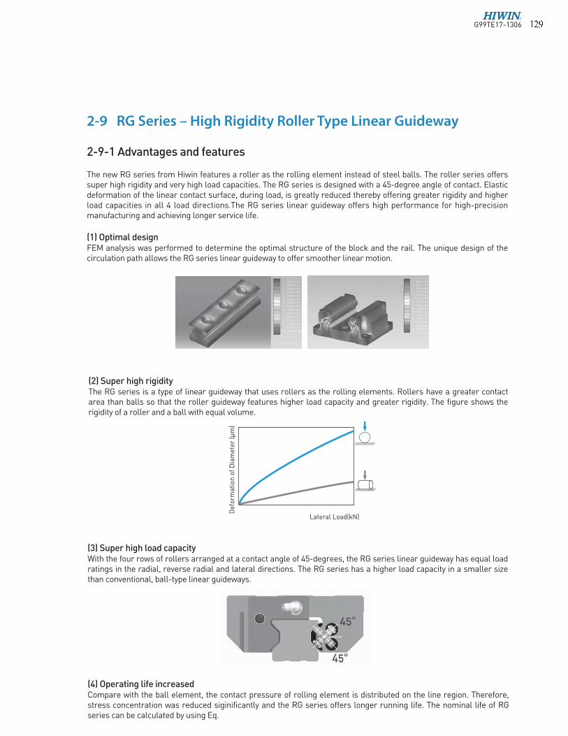
(1) Optimal designFEM analysis was performed to determine the optimal structure of the block and the rail. The unique design of the circulation path allows the RG series linear guideway to offer smoother linear motion.
(2) Super high rigidityThe RG series is a type of linear guideway that uses rollers as the rolling elements. Rollers have a greater contact area than balls so that the roller guideway features higher load capacity and greater rigidity. The figure shows the rigidity of a roller and a ball with equal volume.
Lateral Load(kN)
Def
orm
atio
n o
f D
iam
eter
(µ
m)
(3) Super high load capacityWith the four rows of rollers arranged at a contact angle of 45-degrees, the RG series linear guideway has equal load ratings in the radial, reverse radial and lateral directions. The RG series has a higher load capacity in a smaller size than conventional, ball-type linear guideways.
(4) Operating life increasedCompare with the ball element, the contact pressure of rolling element is distributed on the line region. Therefore, stress concentration was reduced siginificantly and the RG series offers longer running life. The nominal life of RG series can be calculated by using Eq.
G99TE17-1306� � �

Linear GuidewaysRG Series
Tested model 1: RGH35CAPreload: ZA classMax. Speed: 60m/minAcceleration: 1GStroke: 0.55mLubrication: grease held every 100kmExternal load: 15kNTraveling distance: 1135km
Test results:The nominal life of RGH35CA is 1000km. After traveling 1135km, fatigue flaking did not appear on the surface of the raceway or rollers.
2. Durability Test
Tested model 2: RGW35CCPreload: ZA classMax. Speed: 120m/minAcceleration: 1GStroke: 2mLubrication: oil feed rate: 0.3cm3/hrExternal load: 0kNTraveling distance: 15000km
Test results:Fatigue flaking did not appear on the surface of the raceway or rollers after traveling 15000km.
Table 2-9-1
(5) Test Data 1. Nominal life test
2-9-2 Construction of RG Series
Bottom seal
End Cap
Block
End seal(Double seals and scraper)
Grease nipple
Cap
Rail
Rollers
Circulation path
Rolling circulation system: Block, Rail, End cap, Circulation path, rollers
Lubrication system: Grease nipple and piping joint Dust protection system: End seal, Bottom seal,
Cap, Double seals and Scraper
Model of the test system
Note: The data listed are from samples.
G99TE17-1306� � �

(2) Interchangeable typeModel Number of RG Block
E2: Self-LubricantRG Series
Block Type
W : Flange Type
H : Square Type
E: Special Block
None: Standard block
Dust Protection2
Precision Code : H, P
Preload Code : Z0, ZA
Model size
15,20,25, 30, 35, 45, 55, 65
Load Type
C : Heavy Load
H : Super Heavy Load
RG W 25 C A E ZA P + ZZ/E2
Block Mounting Type
A : Mounting From Top
C : Top or Bottom
Model Number of RG Rail
RG Series
Rail Mounting Type
R : Mounting From Top
T : Bottom
Rail Length (mm)
E: Special Rail,
None: Standard Rail
RC:Reinforced Cap
Precision Code : H, PInterchangeable Rail
Model size
15,20,25, 30, 35, 45, 55, 65
RG R 25 R 1240 E P + RC
2-9-3 Model Number of RG seriesRG series linear guideways are classified into non-interchangeable and interchangeable types. The sizes of these two types are the same as one another. The main difference is that the interchangeable type of blocks and rails can be freely exchanged and they can maintain P-class accuracy. Because of strict dimensional control, the interchangeable type linear guideways are a wise choice for customers when rails do not need to be matched for an axis. The model number of the RG series identifies the size, type, accuracy class, preload class, etc.
Note: 1. Roman numerals are used to express the number of matched sets of rails.
2. For dust protection, no symbol is required if it is standard (end seal and bottom seal only).
ZZ: End seal, bottom seal and scraper KK: Double seals, bottom seal and scraper DD: Double seals and bottom seal
Block Type
W : Flange Type
H : Square Type
RG Series
Model size
15,20,25, 30, 35, 45, 55, 65
No. of Blocks per Rail
Rail Length (mm)
E: Special RailNone: Standard Rail
Rail Mounting Type
R : Mounting From Top
T : Bottom
Preload Code: Z0, ZA, ZB
Precision Code: H, P, SP, UP
No. of Rails per matched set 1Dust Protection2
RC:
Reinforced Cap
Load Type
C : Heavy Load
H : Super Heavy Load
Block Mounting
A : Mounting From Top
C : Top or Bottom
E: Special Block
None: Standard Block
(1) Non-interchangeable type
E2: Self-Lubricant
RG W 35 C C E 2 R 1640 E ZA P II + KK/E2/RC
G99TE17-1306� � �

Linear GuidewaysRG Series
2-9-4 Types(1) Block typesHIWIN offers two types of guide blocks, flange and square type. Because of the low assembly height and large mounting surface, the flange type is excellent for heavy moment load applications.
Type Model Shape HeightRail Length
Main Applications
(mm) (mm)
RGH-CA RGH-HA
28
90
100
4000
Automation Systems
Transportation equipment
CNC machining centers
Heavy duty cutting machines
CNC grinding machines
Injection molding machines
Plano millers
Devices requiring high rigidity
Devices requiring high load
capacity
Electric discharge machines
RGW-CC RGW-HC
24
90
100
4000
Sq
uar
e F
lan
ge
(2) Rail typesIn addition to the standard top mounting type, HIWIN also offers the bottom mounting type of rails.
Table 2-9-3 Rail Types
Mounting from Top Mounting from Bottom
Table 2-9-2 Block Types
G99TE17-1306� � �
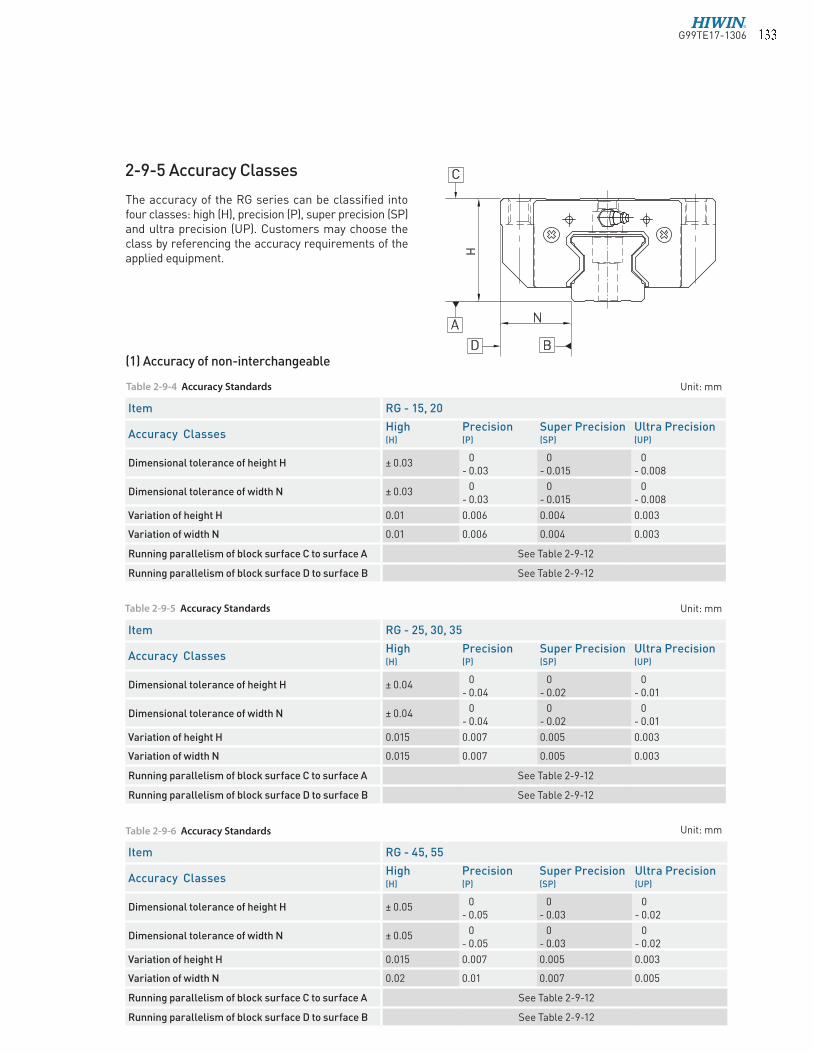
The accuracy of the RG series can be classified into four classes: high (H), precision (P), super precision (SP) and ultra precision (UP). Customers may choose the class by referencing the accuracy requirements of the applied equipment.
Table 2-9-5 Accuracy Standards
Table 2-9-4 Accuracy Standards
Unit: mm
Unit: mm
2-9-5 Accuracy Classes
H
N
D B
C
A
Table 2-9-6 Accuracy Standards Unit: mm
Item RG - 25, 30, 35
Accuracy ClassesHigh Precision Super Precision Ultra Precision(H) (P) (SP) (UP)
Dimensional tolerance of height H ± 0.04 0- 0.04
0- 0.02
0- 0.01
Dimensional tolerance of width N ± 0.04 0- 0.04
0- 0.02
0- 0.01
Variation of height H 0.015 0.007 0.005 0.003
Variation of width N 0.015 0.007 0.005 0.003
Running parallelism of block surface C to surface A See Table 2-9-12
Running parallelism of block surface D to surface B See Table 2-9-12
Item RG - 15, 20
Accuracy ClassesHigh Precision Super Precision Ultra Precision(H) (P) (SP) (UP)
Dimensional tolerance of height H ± 0.03 0- 0.03
0- 0.015
0- 0.008
Dimensional tolerance of width N ± 0.03 0- 0.03
0- 0.015
0- 0.008
Variation of height H 0.01 0.006 0.004 0.003
Variation of width N 0.01 0.006 0.004 0.003
Running parallelism of block surface C to surface A See Table 2-9-12
Running parallelism of block surface D to surface B See Table 2-9-12
Item RG - 45, 55
Accuracy ClassesHigh Precision Super Precision Ultra Precision(H) (P) (SP) (UP)
Dimensional tolerance of height H ± 0.05 0- 0.05
0- 0.03
0- 0.02
Dimensional tolerance of width N ± 0.05 0- 0.05
0- 0.03
0- 0.02
Variation of height H 0.015 0.007 0.005 0.003
Variation of width N 0.02 0.01 0.007 0.005
Running parallelism of block surface C to surface A See Table 2-9-12
Running parallelism of block surface D to surface B See Table 2-9-12
(1) Accuracy of non-interchangeable
G99TE17-1306� � �

Linear GuidewaysRG Series
Item RG - 65
Accuracy ClassesHigh Precision Super Precision Ultra Precision(H) (P) (SP) (UP)
Dimensional tolerance of height H ± 0.07 0- 0.07
0- 0.05
0- 0.03
Dimensional tolerance of width N ± 0.07 0- 0.07
0- 0.05
0- 0.03
Variation of height H 0.02 0.01 0.007 0.005
Variation of width N 0.025 0.015 0.01 0.007
Running parallelism of block surface C to surface A See Table 2-9-12
Running parallelism of block surface D to surface B See Table 2-9-12
Table 2-9-7 Accuracy Standards Unit: mm
(2) Accuracy of interchangeable
Item RG - 25, 30, 35
Accuracy Classes High (H) Precision (P)
Dimensional tolerance of height H ± 0.04 ± 0.02
Dimensional tolerance of width N ± 0.04 ± 0.02
Variation of height H 0.015 0.007
Variation of width N 0.015 0.007
Running parallelism of block surface C to surface A See Table 2-9-12
Running parallelism of block surface D to surface B See Table 2-9-12
Item RG - 15, 20
Accuracy Classes High (H) Precision (P)
Dimensional tolerance of height H ± 0.03 ± 0.015
Dimensional tolerance of width N ± 0.03 ± 0.015
Variation of height H 0.01 0.006
Variation of width N 0.01 0.006
Running parallelism of block surface C to surface A See Table 2-9-12
Running parallelism of block surface D to surface B See Table 2-9-12
Item RG - 45, 55
Accuracy Classes High (H) Precision (P)
Dimensional tolerance of height H ± 0.05 ± 0.025
Dimensional tolerance of width N ± 0.05 ± 0.025
Variation of height H 0.015 0.007
Variation of width N 0.02 0.01
Running parallelism of block surface C to surface A See Table 2-9-12
Running parallelism of block surface D to surface B See Table 2-9-12
Table 2-9-9 Accuracy Standards
Table 2-9-8 Accuracy Standards
Unit: mm
Unit: mm
Table 2-9-10 Accuracy Standards Unit: mm
G99TE17-1306� � �
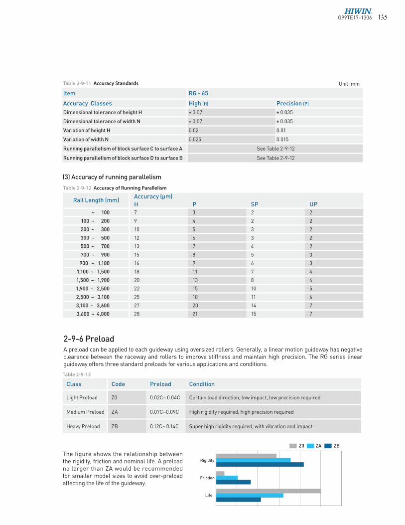
2-9-6 PreloadA preload can be applied to each guideway using oversized rollers. Generally, a linear motion guideway has negative clearance between the raceway and rollers to improve stiffness and maintain high precision. The RG series linear guideway offers three standard preloads for various applications and conditions.
The figure shows the relationship between the rigidity, friction and nominal life. A preload no larger than ZA would be recommended for smaller model sizes to avoid over-preload affecting the life of the guideway.
Class Code Preload Condition
Light Preload Z0 0.02C~ 0.04C Certain load direction, low impact, low precision required
Medium Preload ZA 0.07C~0.09C High rigidity required, high precision required
Heavy Preload ZB 0.12C~ 0.14C Super high rigidity required, with vibration and impact
Rigidity
Friction
Life
ZBZAZ0
Table 2-9-13
Rail Length (mm)Accuracy (µm)
H P SP UP
~ 100 7 3 2 2
100 ~ 200 9 4 2 2
200 ~ 300 10 5 3 2
300 ~ 500 12 6 3 2
500 ~ 700 13 7 4 2
700 ~ 900 15 8 5 3
900 ~ 1,100 16 9 6 3
1,100 ~ 1,500 18 11 7 4
1,500 ~ 1,900 20 13 8 4
1,900 ~ 2,500 22 15 10 5
2,500 ~ 3,100 25 18 11 6
3,100 ~ 3,600 27 20 14 7
3,600 ~ 4,000 28 21 15 7
Table 2-9-12 Accuracy of Running Parallelism
Item RG - 65
Accuracy Classes High (H) Precision (P)
Dimensional tolerance of height H ± 0.07 ± 0.035
Dimensional tolerance of width N ± 0.07 ± 0.035
Variation of height H 0.02 0.01
Variation of width N 0.025 0.015
Running parallelism of block surface C to surface A See Table 2-9-12
Running parallelism of block surface D to surface B See Table 2-9-12
Table 2-9-11 Accuracy Standards Unit: mm
(3) Accuracy of running parallelism
G99TE17-1306� � �

Linear GuidewaysRG Series
The standard location of the grease fitting is at both ends of the block, but the nipple can be mounted in the side or the top of block. For lateral installation, we recommend that the nipple be mounted at the non-reference side, otherwise please contact us. It is possible to carry out the lubrication by using an oil-piping joint. The figure shows the locations of the grease fitting.
do
W
O Ring
Size O-Ring
Lube hole at top:max. permissible depth for piercing
do (mm) W (mm) Tmax (mm)
RG15 2.5±0.15 1.5±0.15 3.45
RG20 2.5±0.15 1.5±0.15 4
RG25 7.5±0.15 1.5±0.15 5.8
RG30 7.5±0.15 1.5±0.15 6.2
RG35 7.5±0.15 1.5±0.15 8.65
RG45 7.5±0.15 1.5±0.15 9.5
RG55 7.5±0.15 1.5±0.15 11.6
RG65 7.5±0.15 1.5±0.15 14.5
dia.0.8
Tmax
Size Medium Load(cm3) Heavy Load(cm3) Size Medium Load(cm3) Heavy Load(cm3)
RG15 3 - RG35 12 14
RG20 5 6 RG45 19 23
RG25 7 8 RG55 28 35
RG30 9 10 RG65 52 63
Mounting location
The oil amount for a block filled with grease
Table 2-9-14 O-Ring size and max. permissible depth for piercing
Table 2-9-15 The oil amount for a block !lled with grease
Frequency of replenishment
Check the grease every 100 km, or every 3-6 months.
RG15 RG45RG55RG65
RG25RG30RG35
NO.34320001 NO.34320003
NO.34310003(OPTION) NO.3431000B(OPTION)
M6x0.75P
M6x0.75P
PT1/8
PT1/8M4x0.7P
RG45RG55RG65
RG25RG30RG35
NO.34310002
RG20
2-9-7 Lubrication(1) Grease
Grease nipple
G99TE17-1306� � �
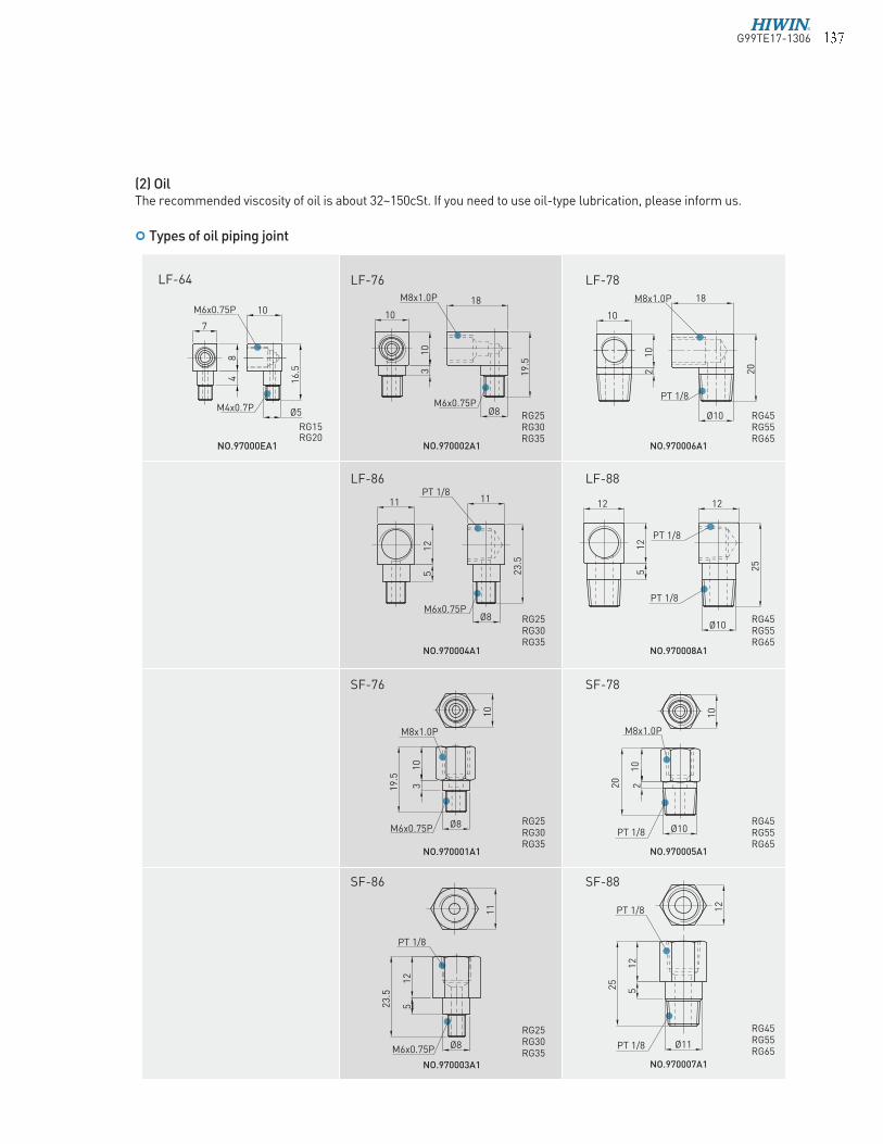
(2) OilThe recommended viscosity of oil is about 32~150cSt. If you need to use oil-type lubrication, please inform us.
Types of oil piping joint
PT 1/8
M8x1.0P
10
20
2
Ø10
19
.5
M8x1.0P 18
10
M6x0.75P
3
Ø8
PT 1/8
M6x0.75PØ8
PT 1/8
PT 1/8
12
25
5
Ø11
PT 1/8
PT 1/8
12
25
Ø10
5
11 12
10
12
NO.970003A1
NO.970005A1
NO.970002A1
NO.970004A1
NO.970006A1
NO.970007A1
NO.970008A1
12
23
.5
5
SF-86
SF-78
SF-88
LF-76
LF-86
LF-78
LF-88
11
10
12
M6x0.75P
M8x1.0P
10
19
.5
3
Ø8
10
NO.970001A1
SF-76
RG25RG30RG35
RG25RG30RG35
RG45RG55RG65
RG25RG30RG35
RG25RG30RG35
RG45RG55RG65
RG45RG55RG65
RG45RG55RG65
RG15RG20
NO.97000EA1
LF-64
8
16
.5
M6x0.75P
M4x0.7P
4
Ø5
10
7
M8x1.0P
PT 1/8
18
10
20
2
Ø10
10
PT 1/8
12
23
.5
M6x0.75P Ø8
5
11
G99TE17-1306� � �

Linear GuidewaysRG Series
2
1
Scraper
End seal End seal
Bottom Seal End seal
Scraper
No symbol: Standard Protection (End seal + Bottom Seal)
KK (Double seals + Bottom Seal + Scraper) DD (Double seals + Bottom Seal)
ZZ (End seal + Bottom Seal + Scraper)
End seal
Table 2-9-17
2-9-8 Dust Proof Accessories(1) Codes of accessoriesIf the following accessories are needed, please add the code followed by the model number.
Oil feeding rate
Size feed rate
(cm3/hr)
RG15 0.14
RG20 0.14
RG25 0.167
RG30 0.2
RG35 0.23
RG45 0.3
RG55 0.367
RG65 0.433
Table 2-9-16 oil feed rate
G99TE17-1306� �

Size Thickness (t2) Size Thickness (t2)
(mm) (mm)
RG15 SC 1.0 RG35 SC 1.5
RG20 SC 1.0 RG45 SC 1.5
RG25 SC 1.0 RG55 SC 1.5
RG30 SC 1.5 RG65 SC 1.5
(3) Double sealsEnhances the wiping effect, foreign matter can be completely wiped off.
Size Thickness (t1) Size Thickness (t1)
(mm) (mm)
RG15 ES 2.2 RG35 ES 2.5
RG20 ES 2.2 RG45 ES 3.6
RG25 ES 2.2 RG55 ES 3.6
RG30 ES 2.4 RG65 ES 4.4
Table 2-9-19 Dimensions of scraper
(4) ScraperThe scraper removes high-temperature iron chips and larger foreign objects.
Table 2-9-18 Dimensions of end seal
Rail size Bolt sizeDiameter(D) Thickness(H)
Rail size Bolt sizeDiameter(D) Thickness(H)
(mm) (mm) (mm) (mm)
RGR15 M4 7.65 1.1 RGR35 M8 14.3 3.3
RGR20 M5 9.65 2.2 RGR45 M12 20.3 4.6
RGR25 M6 11.3 2.5 RGR55 M14 23.5 5.5
RGR30 M8 14.3 3.3 RGR65 M16 26.6 5.5
Table 2-9-20 Dimensions of Bolt Caps for Rail Mounting Holes
(5) Bolt caps for rail mounting holesCaps are used to cover the mounting holes to prevent chips or other foreign objects from collecting in the holes. The caps will be enclosed in each rail package.
Ø
(2) End seal and bottom seal To prevent life reduction caused by iron chips or dust entering the block.
G99TE17-1306� � �

Linear GuidewaysRG Series
Size Resistance N (kgf) Size Resistance N (kgf)
RG15 1.96 (0.2) RG35 3.53 (0.36)
RG20 2.45 (0.25) RG45 4.21 (0.43)
RG25 2.74 (0.28) RG55 5.09 (0.52)
RG30 3.31 (0.31) RG65 6.66 (0.68)
2-9-9 FrictionThe maximum value of resistance per end seal are as shown in the table.
Table 2-9-22 Seal Resistance
SizeOverall block length (L)
SS ZZ DD KK
RG15C 68 70 72.4 74.4
RG20C 86 88 90.4 92.4
RG20H 106 108 110.4 112.4
RG25C 97.9 99.9 102.3 104.3
RG25H 114.4 116.4 118.8 120.8
RG30C 109.8 112.8 114.6 117.6
RG30H 131.8 134.8 136.6 139.6
RG35C 124 127 129 132
RG35H 151.5 154.5 156.5 159.5
RG45C 153.2 156.2 160.4 163.4
RG45H 187 190 194.2 197.2
RG55C 183.7 186.7 190.9 193.9
RG55H 232 235 239.2 242.2
RG65C 232 235 240.8 243.8
RG65H 295 298 303.8 306.8
Table 2-9-21 Overall block length
(6) Dimensions of block equipped with the dustproof parts
unit: mm
L
G99TE17-1306� � �

SizePreload classes
Light Preload (Z0) Medium Preload (ZA) Heavy Preload (ZB)
K 2.2×10⁻⁴ 1.7×10⁻⁴ 1.2×10⁻⁴
SizePreload classes
Light Preload (Z0) Medium Preload (ZA) Heavy Preload (ZB)
RG15 5 3 3
RG20 8 6 4
RG25 9 7 5
RG30 11 8 6
RG35 14 10 7
RG45 17 13 9
RG55 21 14 11
RG65 27 18 14
Table 2-9-24 Coe"cient of tolerance of height
2-9-10 The Accuracy Tolerance of Mounting Surface(1) The accuracy tolerance of rail-mounting surfaceAs long as the accuracy requirements of the mounting surfaces shown in the following tables are met, the high accuracy, high rigidity and long life of the RG series linear guideway will be maintained without any difficulty.
unit: µm
The parallelism tolerance of reference surface (P)
P
a
C
S1
0.010 C
0.010Accuracy requirement for all rail-mounting reference surfaces
The accuracy tolerance of reference surface height (S1)
S1 : Max. tolerance of heighta : Distance between paired railsK : Coefficient of tolerance of height
S1 = a × K
Table 2-9-23 Max. Parallelism Tolerance (P)
G99TE17-1306 � � �

Linear GuidewaysRG Series
(2) The accuracy tolerance of block-mounting surface
The tolerance of the height of reference surface when two or more pieces are used in parallel (S2)
b
A
0.010
S2
A 0.010 A
B0.010 A 0.010 B
0.010Accuracy requirement for all block-mounting reference surfaces
S2 : Max. tolerance of heightb : Distance between paired blocks
S2 = b × 4.2 × 10⁻⁵
The tolerance of the height of reference surface when two or more pieces are used in parallel (S3)
S3 : Max. tolerance of heightc : Distance between paired blocks
S3 = c × 4.2 × 10⁻⁵
c
S3
0.010
A
0.010 A
Accuracy requirement for all block-mounting reference surfaces
G99TE17-1306� �
Size
Max. radius of fillets
Max. radius of fillets
Shoulder height of the rail
Shoulder height of the block
Clearance under block
r1 (mm) r2 (mm) E1 (mm) E2 (mm) H1 (mm)
RG15 0.5 0.5 4 4 4
RG20 0.5 0.5 5 5 5
RG25 1.0 1.0 5 5 5.5
RG30 1.0 1.0 5 5 6
RG35 1.0 1.0 6 6 6.5
RG45 1.0 1.0 7 8 8
RG55 1.5 1.5 9 10 10
RG65 1.5 1.5 10 10 12
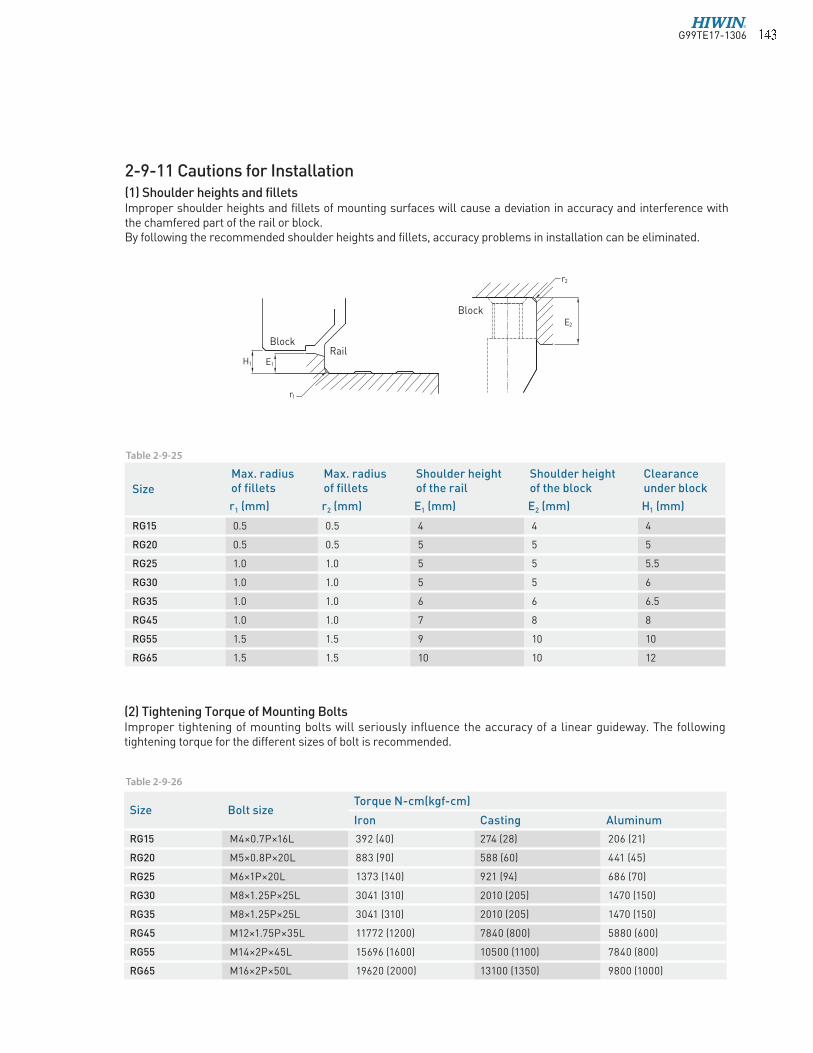
(2) Tightening Torque of Mounting BoltsImproper tightening of mounting bolts will seriously influence the accuracy of a linear guideway. The following tightening torque for the different sizes of bolt is recommended.
Table 2-9-25
Table 2-9-26
2-9-11 Cautions for Installation(1) Shoulder heights and filletsImproper shoulder heights and fillets of mounting surfaces will cause a deviation in accuracy and interference with the chamfered part of the rail or block.By following the recommended shoulder heights and fillets, accuracy problems in installation can be eliminated.
Size Bolt sizeTorque N-cm(kgf-cm)
Iron Casting Aluminum
RG15 M4×0.7P×16L 392 (40) 274 (28) 206 (21)
RG20 M5×0.8P×20L 883 (90) 588 (60) 441 (45)
RG25 M6×1P×20L 1373 (140) 921 (94) 686 (70)
RG30 M8×1.25P×25L 3041 (310) 2010 (205) 1470 (150)
RG35 M8×1.25P×25L 3041 (310) 2010 (205) 1470 (150)
RG45 M12×1.75P×35L 11772 (1200) 7840 (800) 5880 (600)
RG55 M14×2P×45L 15696 (1600) 10500 (1100) 7840 (800)
RG65 M16×2P×50L 19620 (2000) 13100 (1350) 9800 (1000)
r2
E2
r1
E1H1
BlockRail
Block
G99TE17-1306 � � �

Linear GuidewaysRG Series
Item RGR15 RGR20 RGR25 RGR30 RGR35 RGR45 RGR55 RGR65
Standard Length L(n)
160 (5) 220 (7) 220 (7) 280 (7) 280 (7) 570 (11) 780 (13) 1,270 (17)
220 (7) 280 (9) 280 (9) 440 (11) 440 (11) 885 (17) 1020 (17) 1,570 (21)
340 (11) 340 (11) 340 (11) 600 (15) 600 (15) 1,200 (23) 1,260 (21) 2,020 (27)
460 (15) 460 (15) 460 (15) 760 (19) 760 (19) 1,620 (31) 1,500 (25) 2,620 (35)
580 (19) 640 (21) 640 (21) 1,000 (25) 1,000 (25) 2,040 (39) 1,980 (33) -
700 (23) 820 (27) 820 (27) 1,640 (41) 1,640 (41) 2,460 (47) 2,580 (43) -
940 (31) 1000 (33) 1,000 (33) 2,040 (51) 2,040 (51) 2,985 (57) 2,940 (49)
1120 (37) 1180 (39) 1,240 (41) 2,520 (63) 2,520 (63) 3,090 (59) 3,060 (51) -
1360 (45) 1360 (45) 1,600 (53) 3,000 (75) 3,000 (75) - - -
Pitch (P) 30 30 30 40 40 52.5 60 75
Distance to End (Es) 20 20 20 20 20 22.5 30 35
Max. Standard Length 4,000 (133) 4,000 (133) 4,000 (133) 4,000 (100) 4,000 (100) 3,982.5 (76) 3,960 (66) 3,970 (53)
Max. Length 4,000 4,000 4,000 4,000 4,000 4,000 4,000 4,000
unit: mmTable 2-9-27
2-9-12 Standard and Maximum Lengths of RailHIWIN offers a number of standard rail lengths. Standard rail lengths feature end mounting hole placements set to predetermined values (E). For non-standard rail lengths, be sure to specify the E-value to be no greater than 1/2 the pitch (P) dimension. An E-value greater than this will result in unstable rail ends.
E P
L
E
n ( )n=(Number of rail mounting holes)
Note : 1. Tolerance of E value for standard rail is 0.5~-0.5 mm. Tolerance of E value for jointed rail is 0~-0.3 mm. 2. Maximum standard length means the max. rail length with standard E value on both sides.
3. If different E value is needed, please contact HIWIN.
G99TE17-1306� � �
W
B
T
H
L G
hC
N
E P E
B1 L 1
ØD
Ød
H2
H R
H3
H 1
6-Mxl
W R
MRMP
MY
K1
K2
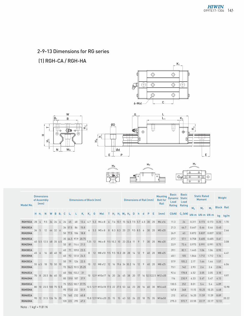
2-9-13 Dimensions for RG series
(1) RGH-CA / RGH-HA
Note : 1 kgf = 9.81 N
Model No.
Dimensions
of Assembly
(mm)
Dimensions of Block (mm) Dimensions of Rail (mm)
Mounting
Bolt for
Rail
Basic
Dynamic
Load
Rating
Basic
Static
Load
Rating
Static Rated Moment
Weight
MR
kN-m
MP
kN-m
MY
kN-m
Block
kg
Rail
kg/mH H1 N W B B1 C L1 L K1 K2 G Mxl T H2 H3 WR HR D h d P E (mm) C(kN) C0 (kN)
RGH15CA 28 4 9.5 34 26 4 26 45 68 13.4 4.7 5.3 M4 x 8 6 7.6 10.1 15 16.5 7.5 5.7 4.5 30 20 M4 x16 11.3 24 0.311 0.173 0.173 0.20 1.70
RGH20CA34 5 12 44 32 6
36 57.5 86 15.86 5.3 M5 x 8 8 8.3 8.3 20 21 9.5 8.5 6 30 20 M5 x20
21.3 46.7 0.647 0.46 0.46 0.402.66
RGH20HA 50 77.5 106 18.8 26.9 63 0.872 0.837 0.837 0.53
RGH25CA40 5.5 12.5 48 35 6.5
35 64.5 97.9 20.757.25 12 M6 x 8 9.5 10.2 10 23 23.6 11 9 7 30 20 M6 x20
27.7 57.1 0.758 0.605 0.605 0.613.08
RGH25HA 50 81 114.4 21.5 33.9 73.4 0.975 0.991 0.991 0.75
RGH30CA45 6 16 60 40 10
40 71 109.8 23.58 12 M8 x10 9.5 9.5 10.3 28 28 14 12 9 40 20 M8 x25
39.1 82.1 1.445 1.06 1.06 0.904.41
RGH30HA 60 93 131.8 24.5 48.1 105 1.846 1.712 1.712 1.16
RGH35CA55 6.5 18 70 50 10
50 79 124 22.510 12 M8 x12 12 16 19.6 34 30.2 14 12 9 40 20 M8 x25
57.9 105.2 2.17 1.44 1.44 1.576.06
RGH35HA 72 106.5 151.5 25.25 73.1 142 2.93 2.6 2.6 2.06
RGH45CA70 8 20.5 86 60 13
60 106 153.2 3110 12.9 M10x17 16 20 24 45 38 20 17 14 52.5 22.5 M12 x35
92.6 178.8 4.52 3.05 3.05 3.189.97
RGH45HA 80 139.8 187 37.9 116 230.9 6.33 5.47 5.47 4.13
RGH55CA80 10 23.5 100 75 12.5
75 125.5 183.7 37.7512.5 12.9 M12x18 17.5 22 27.5 53 44 23 20 16 60 30 M14 x45
130.5 252 8.01 5.4 5.4 4.8913.98
RGH55HA 95 173.8 232 51.9 167.8 348 11.15 10.25 10.25 6.68
RGH65CA90 12 31.5 126 76 25
70 160 232 60.815.8 12.9 M16 x20 25 15 15 63 53 26 22 18 75 35 M16x50
213 411.6 16.20 11.59 11.59 8.8920.22
RGH65HA 120 223 295 67.3 275.3 572.7 22.55 22.17 22.17 12.13
G99TE17-1306 � � �
Linear GuidewaysRG Series
W
B
T
H
N
B1
H1
W R
H2
T1
C
6-M C1
L G
E P
h
E
L 1
K1
H 3
ØD
Ød
H R
MRMP
MY
K2
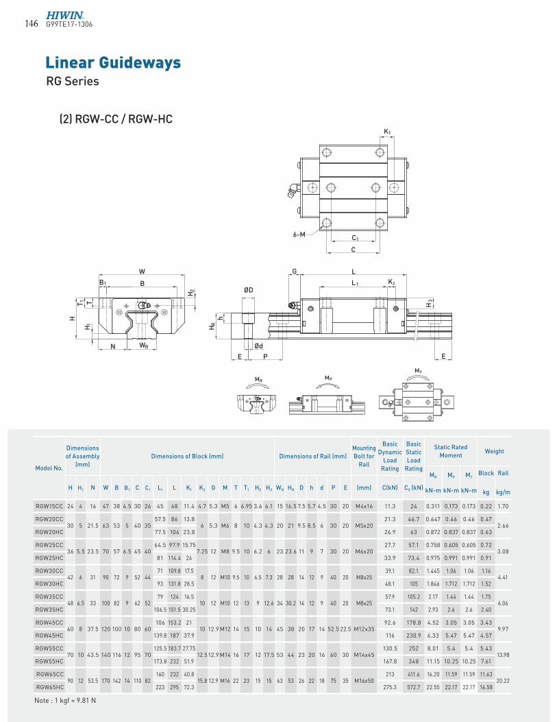
(2) RGW-CC / RGW-HC
Note : 1 kgf = 9.81 N
Model No.
Dimensions
of Assembly
(mm)
Dimensions of Block (mm) Dimensions of Rail (mm)
Mounting
Bolt for
Rail
Basic
Dynamic
Load
Rating
Basic
Static
Load
Rating
Static Rated
MomentWeight
MR
kN-m
MP
kN-m
MY
kN-m
Block
kg
Rail
kg/mH H1 N W B B1 C C1 L1 L K1 K2 G M T T1 H2 H3 WR HR D h d P E (mm) C(kN) C0 (kN)
RGW15CC 24 4 16 47 38 4.5 30 26 45 68 11.4 4.7 5.3 M5 6 6.95 3.6 6.1 15 16.5 7.5 5.7 4.5 30 20 M4x16 11.3 24 0.311 0.173 0.173 0.22 1.70
RGW20CC30 5 21.5 63 53 5 40 35
57.5 86 13.86 5.3 M6 8 10 4.3 4.3 20 21 9.5 8.5 6 30 20 M5x20
21.3 46.7 0.647 0.46 0.46 0.472.66
RGW20HC 77.5 106 23.8 26.9 63 0.872 0.837 0.837 0.63
RGW25CC36 5.5 23.5 70 57 6.5 45 40
64.5 97.9 15.757.25 12 M8 9.5 10 6.2 6 23 23.6 11 9 7 30 20 M6x20
27.7 57.1 0.758 0.605 0.605 0.723.08
RGW25HC 81 114.4 24 33.9 73.4 0.975 0.991 0.991 0.91
RGW30CC42 6 31 90 72 9 52 44
71 109.8 17.58 12 M10 9.5 10 6.5 7.3 28 28 14 12 9 40 20 M8x25
39.1 82.1 1.445 1.06 1.06 1.164.41
RGW30HC 93 131.8 28.5 48.1 105 1.846 1.712 1.712 1.52
RGW35CC48 6.5 33 100 82 9 62 52
79 124 16.510 12 M10 12 13 9 12.6 34 30.2 14 12 9 40 20 M8x25
57.9 105.2 2.17 1.44 1.44 1.756.06
RGW35HC 106.5 151.5 30.25 73.1 142 2.93 2.6 2.6 2.40
RGW45CC60 8 37.5 120 100 10 80 60
106 153.2 2110 12.9 M12 14 15 10 14 45 38 20 17 14 52.5 22.5 M12x35
92.6 178.8 4.52 3.05 3.05 3.439.97
RGW45HC 139.8 187 37.9 116 230.9 6.33 5.47 5.47 4.57
RGW55CC70 10 43.5 140 116 12 95 70
125.5 183.7 27.7512.512.9 M14 16 17 12 17.5 53 44 23 20 16 60 30 M14x45
130.5 252 8.01 5.4 5.4 5.4313.98
RGW55HC 173.8 232 51.9 167.8 348 11.15 10.25 10.25 7.61
RGW65CC90 12 53.5 170 142 14 110 82
160 232 40.815.8 12.9 M16 22 23 15 15 63 53 26 22 18 75 35 M16x50
213 411.6 16.20 11.59 11.59 11.6320.22
RGW65HC 223 295 72.3 275.3 572.7 22.55 22.17 22.17 16.58
G99TE17-1306� � �
E P
L
E
h
HR
WRS
Model No.Dimensions of Rail (mm) Weight
WR HR S h P E (kg/m)
RGR15T 15 16.5 M5×0.8P 8 30 20 1.86
RGR20T 20 21 M6×1P 10 30 20 2.76
RGR25T 23 23.6 M6×1P 12 30 20 3.36
RGR30T 28 28 M8×1.25P 15 40 20 4.82
RGR35T 34 30.2 M8×1.25P 17 40 20 6.48
RGR45T 45 38 M12×1.75P 24 52.5 22.5 10.83
RGR55T 53 44 M14×2P 24 60 30 15.15
RGR65T 63 53 M20×2.5P 30 75 35 21.24
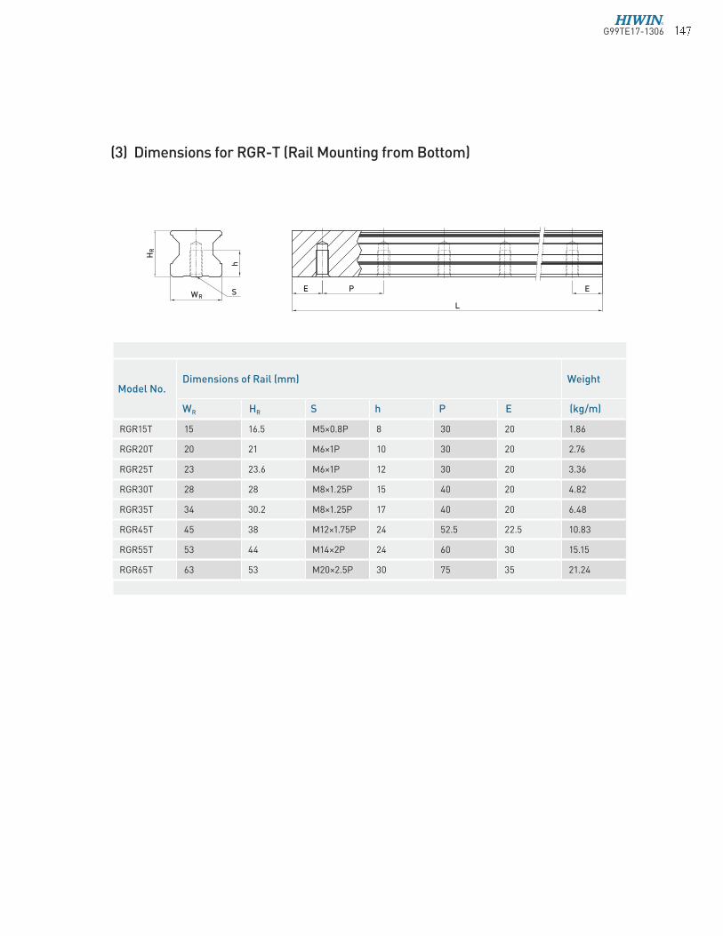
(3) Dimensions for RGR-T (Rail Mounting from Bottom)
G99TE17-1306 � � �