2-1.12b(2) dbe commitment submittal -...
TRANSCRIPT

REVISED STANDARD SPECIFICATIONS DATED10-19-18
ORGANIZATIONRevised standard specifications are under headings that correspond with the main-section headings of the Standard Specifications. A main-section heading is a heading shown in the table of contents of the Standard Specifications. A date under a main-section heading is the date of the latest revision to the section.
Each revision to the Standard Specifications begins with a revision clause that describes or introduces a revision to the Standard Specifications. For a revision clause that describes a revision, the date on the right above the clause is the publication date of the revision. For a revision clause that introduces a revision, the date on the right above a revised term, phrase, clause, paragraph, or section is the publication date of the revised term, phrase, clause, paragraph, or section. For a multiple-paragraph or multiple-section revision, the date on the right above a paragraph or section is the publication date of the paragraphs or sections that follow.
Any paragraph added or deleted by a revision clause does not change the paragraph numbering of the Standard Specifications for any other reference to a paragraph of the Standard Specifications.
^^^^^^^^^^^^^^^^^^^^^^^^^^^^^^^^^^^^^^^^^^^^^^^^^^^^^^^^^^^^
DIVISION I GENERAL PROVISIONS1 GENERAL
10-19-18Add between the 1st and 2nd paragraphs of section 1-1.01:
10-19-18Global revisions are changes to contract documents not specific to a section of the Standard Specifications. In each contract document at each occurrence, interpret the following terms as shown:
Term Interpretation ConditionsFed-Std-595 AMS Std 595 --
^^^^^^^^^^^^^^^^^^^^^^^^^^^^^^^^^^^^^^^^
2 BIDDING10-19-18
Replace the 5th paragraph of section 2-1.12B(1) with:10-19-18
You are responsible to verify at bid opening the DBE firm is certified as a DBE by the California Unified Certification Program and possesses the most specific available NAICS codes or work codes applicable to the type of work the firm will perform on the Contract.

Replace section 2-1.12B(2) with:10-19-18
2-1.12B(2) DBE Commitment SubmittalSubmit DBE information under section 2-1.33.
Submit a copy of the quote from each DBE shown on the DBE Commitment form that describes the type and dollar amount of work shown on the form no later than 4 p.m. on the 5th day after bid opening. If the last day for submitting the quote falls on a Saturday or holiday, it may be submitted on the next business day with the same effect as if it had been submitted on the 5th day.
Submit a DBE Confirmation form for each DBE shown on the DBE Commitment form to establish that it will be participating in the Contract in the type and dollar amount of work shown on the form. If a DBE is participating as a joint venture partner, submit a copy of the joint venture agreement.
Failure to submit a completed DBE Confirmation form and a copy of the quote from each DBE will result in disallowance of the DBE’s participation.
Add between the 4th and 5th paragraphs of section 2-1.15B:10-19-18
Submit a copy of the quote from each DVBE listed on the Certified DVBE Summary form that describes the type and dollar amount of work shown on the form no later than 4 p.m. on the 4th business day after bid opening.
Add between the 3rd and 4th paragraphs of section 2-1.15C(1):10-19-18
Submit a copy of the quote from each DVBE listed on the Certified DVBE Summary form that describes the type and dollar amount of work shown on the form no later than 4 p.m. on the 4th business day after bid opening.
Add between the 1st and 2nd paragraphs of section 2-1.18C:10-19-18
Failure to submit a completed Certified Small Business Listing for the Non–Small Business Preference form by 4 p.m. on the 2nd business day after bid opening will result in a nonresponsive bid.
Replace section 2-1.33B with:10-19-18
2-1.33B Bid Form Submittal Schedules2-1.33B(1) GeneralThe Bid book includes forms specific to the Contract. The deadlines for the submittal of the forms vary depending on the requirements of each Contract. Determine the requirements of the Contract and submit the forms based on the applicable schedule specified in section 2-1.33B.
Bid forms and information on the form that are due after the time of bid may be submitted at the time of bid.
2-1.33B(2) Federal-Aid Contracts2-1.33B(2)(a) GeneralSection 2-1.33B(2) applies to a federal-aid contract.
2-1.33B(2)(b) Contracts with a DBE Goal2-1.33B(2)(b)(i) GeneralSection 2-1.33B(2)(b) applies if a DBE goal is shown on the Notice to Bidders.
2-1.33B(2)(b)(ii) Bid Form SubmittalSubmit the bid forms according to the schedule shown in the following table:
Bid Form Submittal Schedule for aFederal-Aid Contract with a DBE Goal
Form Submittal deadline
Bid to the Department of Transportation Time of bid except for the public works contractor registration number
Copy of the Bid to the Department of Transportation as submitted at the time of bid with the public works contractor registration number
10 days after bid opening
Subcontractor List Time of bid except for the public works contractor registration number
Copy of the Subcontractor List as submitted at the time of bid with the public works contractor registration number
10 days after bid opening
Small Business Status Time of bidOpt Out of Payment Adjustments for Price Index Fluctuationsa Time of bid
DBE Commitment No later than 4 p.m. on the 5th day after bid openingb
DBE Confirmation No later than 4 p.m. on the 5th day after bid openingb
DBE Good Faith Efforts Documentation No later than 4 p.m. on the 5th day after bid openingb
aSubmit only if you choose the option.bIf the last day for submitting the bid form falls on a Saturday or holiday, it may be submitted on the next business day with the same effect as if it had been submitted on the day specified.
2-1.33B(2)(b)(iii) Reserved2-1.33B(2)(c) Contracts without a DBE Goal2-1.33B(2)(c)(i) GeneralSection 2-1.33B(2)(c) applies if a DBE goal is not shown on the Notice to Bidders.
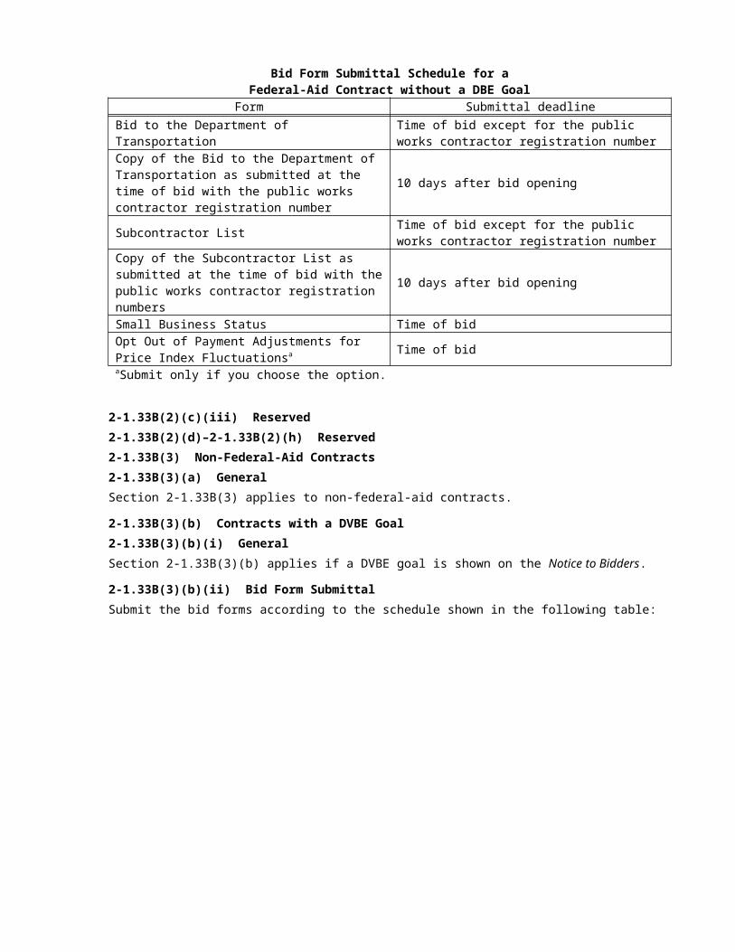
2-1.33B(2)(c)(ii) Bid Form ScheduleSubmit the bid forms according to the schedule shown in the following table:
Bid Form Submittal Schedule for aFederal-Aid Contract without a DBE Goal
Form Submittal deadline
Bid to the Department of Transportation Time of bid except for the public works contractor registration number
Copy of the Bid to the Department of Transportation as submitted at the time of bid with the public works contractor registration number
10 days after bid opening
Subcontractor List Time of bid except for the public works contractor registration number
Copy of the Subcontractor List as submitted at the time of bid with the public works contractor registration numbers
10 days after bid opening
Small Business Status Time of bidOpt Out of Payment Adjustments for Price Index Fluctuationsa Time of bidaSubmit only if you choose the option.

2-1.33B(2)(c)(iii) Reserved2-1.33B(2)(d)–2-1.33B(2)(h) Reserved2-1.33B(3) Non-Federal-Aid Contracts2-1.33B(3)(a) GeneralSection 2-1.33B(3) applies to non-federal-aid contracts.
2-1.33B(3)(b) Contracts with a DVBE Goal2-1.33B(3)(b)(i) GeneralSection 2-1.33B(3)(b) applies if a DVBE goal is shown on the Notice to Bidders.
2-1.33B(3)(b)(ii) Bid Form SubmittalSubmit the bid forms according to the schedule shown in the following table:
Bid Form Submittal Schedule for aNon-Federal-Aid Contract with a DVBE Goal
Form Submittal deadline
Bid to the Department of TransportationTime of bid except for the public works contractor registration number for a joint-venture contract
For a joint-venture contract, copy of the Bid to the Department of Transportation as submitted at the time of bid with the public works contractor registration number
10 days after bid opening
Subcontractor List Time of bidOpt Out of Payment Adjustments for Price Index Fluctuationsa Time of bid
Certified DVBE Summary No later than 4 p.m. on the 4th business day after bid opening
California Company Preference Time of bidRequest for Small Business Preference or Non–Small Business Preferencea Time of bid
Certified Small Business Listing for the Non–Small Business Preferencea
No later than 4 p.m. on the 2nd business day after bid opening
aSubmit only if you choose the option or preference.
2-1.33B(3)(b)(iii) Reserved2-1.33B(3)(c) Contracts without a DVBE Goal2-1.33B(3)(c)(i) GeneralSection 2-1.33B(3)(c) applies if a DVBE goal is not shown on the Notice to Bidders.
2-1.33B(3)(c)(ii) Bid Form SubmittalSubmit the bid forms according to the schedule shown in the following table:
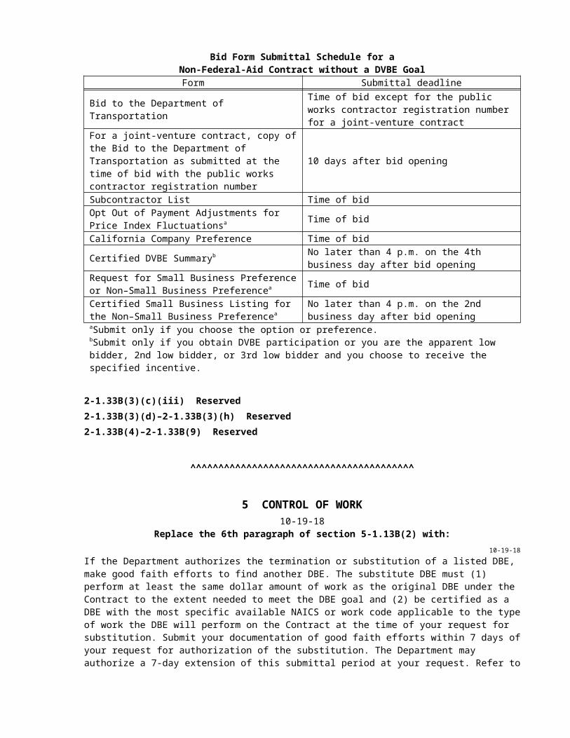
Bid Form Submittal Schedule for aNon-Federal-Aid Contract without a DVBE Goal
Form Submittal deadline
Bid to the Department of Transportation Time of bid except for the public works contractor registration number for a joint-venture contract
For a joint-venture contract, copy of the Bid to the Department of Transportation as submitted at the time of bid with the public works contractor registration number
10 days after bid opening
Subcontractor List Time of bidOpt Out of Payment Adjustments for Price Index Fluctuationsa Time of bid
California Company Preference Time of bid
Certified DVBE Summaryb No later than 4 p.m. on the 4th business day after bid opening
Request for Small Business Preference or Non–Small Business Preferencea Time of bid
Certified Small Business Listing for the Non–Small Business Preferencea
No later than 4 p.m. on the 2nd business day after bid opening
aSubmit only if you choose the option or preference.bSubmit only if you obtain DVBE participation or you are the apparent low bidder, 2nd low bidder, or 3rd low bidder and you choose to receive the specified incentive.
2-1.33B(3)(c)(iii) Reserved2-1.33B(3)(d)–2-1.33B(3)(h) Reserved2-1.33B(4)–2-1.33B(9) Reserved
^^^^^^^^^^^^^^^^^^^^^^^^^^^^^^^^^^^^^^^^
5 CONTROL OF WORK10-19-18
Replace the 6th paragraph of section 5-1.13B(2) with:10-19-18
If the Department authorizes the termination or substitution of a listed DBE, make good faith efforts to find another DBE. The substitute DBE must (1) perform at least the same dollar amount of work as the original DBE under the Contract to the extent needed to meet the DBE goal and (2) be certified as a DBE with the most specific available NAICS or work code applicable to the type of work the DBE will perform on the Contract at the time of your request for substitution. Submit your documentation of good faith efforts within 7 days of your request for authorization of the substitution. The Department may authorize a 7-day extension of this submittal period at your request. Refer to 49 CFR 26 app A for guidance regarding evaluation of good faith efforts to meet the DBE goal.
Replace the 2nd sentence in the 2nd paragraph of section 5-1.13C with:10-19-18
The substitute must be another DVBE, unless DVBEs are not available. The substitute must perform the work originally stated.
Replace the 6th paragraph of section 5-1.13C with:10-19-18
If a DVBE substitute is not available, requests for substitutions of a listed DVBE must include:
1. Contact with the DVBE advocate from the Department and the Department of Veteran Affairs

2. Search results from the Department of General Services’ website of available DVBEs3. Communication with a DVBE community organization nearest the job site, if applicable4. Documented communication with DVBEs describing the work to be performed, the percentage of the
total bid, the corresponding dollar amount, and the responses to the communication
Replace section 5-1.24 with:10-19-18
5-1.24 CONSTRUCTION SURVEYS5-1.24A GeneralThe Department places stakes and marks under chapter 12, "Construction Surveys," of the Department's Surveys Manual.
Submit your request for Department-furnished stakes:
1. Once staking area is ready for stakes2. On a Request for Construction Staking form
After your submittal, the Department starts staking within 2 business days.
Preserve stakes and marks placed by the Department. If the stakes or marks are destroyed, the Department replaces them at the Department's earliest convenience and deducts the cost.
Replace section 5-1.26 with:10-19-18
5-1.26 RESERVED
Replace item 1.2 in the list in the 1st paragraph of section 5-1.43E(2)(b) with:10-19-18
1.2. Have completed training by the Department
Replace item 1.2 in the list in the 1st paragraph of section 5-1.43E(3)(b) with:10-19-18
1.2. Have completed training by the Department
^^^^^^^^^^^^^^^^^^^^^^^^^^^^^^^^^^^^^^^^
6 CONTROL OF MATERIALS10-19-18
Replace section 6-1.03 with:10-19-18
6-1.03 LOCAL MATERIALSLocal material must be rock, sand, gravel, earth, or mineral material other than local borrow, or selected material obtained or produced from a source in the work vicinity, specifically for use on the project. Local borrow must not be a material from an established commercial source.
Upon your request, the Department tests material for quality characteristics from an untested local source. If satisfactory material from that source is used in the work, the Department does not charge you for the tests; otherwise, the Department deducts the test costs.
^^^^^^^^^^^^^^^^^^^^^^^^^^^^^^^^^^^^^^^^
7 LEGAL RELATIONS AND RESPONSIBILITY TO THE PUBLIC10-19-18
Replace the 1st sentence in the 5th paragraph of section 7-1.02K(6)(a) with:10-19-18
Submit copies of your Injury and Illness Prevention Program, Code of Safe Practices, and permits required by Cal/OSHA as informational submittals.
^^^^^^^^^^^^^^^^^^^^^^^^^^^^^^^^^^^^^^^^
8 PROSECUTION AND PROGRESS10-19-18
Replace the row for Safety in the table in the 2nd paragraph of section 8-1.03 with:10-19-18
Safety Injury and Illness Prevention Program, Code of Safe Practices, and job site posters
^^^^^^^^^^^^^^^^^^^^^^^^^^^^^^^^^^^^^^^^
9 PAYMENT10-19-18
Replace section 9-1.07B(5) with:10-19-18
9-1.07B(5) Hot Mix Asphalt Containing Reclaimed Asphalt PavementThe Engineer calculates the quantity of asphalt in HMA containing RAP using the following formula:
Qrap = HMARTT x Xaa
where:Xaa = Xta – [(Xrap x Xra x (Xta-100)) / (100 x (Xra – 100))]
and:Qrap = quantity in tons of asphalt used in HMA containing RAPHMARTT = HMA containing RAP, total tons placedXaa = asphalt content of HMA containing RAP adjusted to exclude the asphalt content in RAP,
expressed as a percentage of the total weight of HMA containing RAPXta = total theoretical asphalt content in HMA containing RAP from the job mix formula, expressed as
a percentage of the total weight of HMA containing RAPXrap = RAP percentage in HMA containing RAP from the job mix formula, expressed as a percentage
of the total dry weight of aggregate in HMA containing RAPXra = average asphalt content of RAP from the job mix formula, expressed as percentage of total
weight of RAP

Replace section 9-1.16C with:10-19-18
9-1.16C Materials On HandA material on hand but not incorporated into the work is eligible for a progress payment if:
1. Compliant with other Contract parts2. Material cost exceeds either of the following:
2.1. $50,0002.2. $25,000 if the requestor is certified as one or more of the following:
2.2.1. DVBE2.2.2. DBE2.2.3. Small business as certified by Department of General Services, Office of Small
Business and Disabled Veteran Business Enterprise Services3. Purchased4. Invoice is submitted5. Stored within the State and you submit evidence that the stored material is subject to the
Department’s control6. Protected from weather and contamination7. Water pollution control measures are established and maintained8. Requested on the Department-furnished form
^^^^^^^^^^^^^^^^^^^^^^^^^^^^^^^^^^^^^^^^^^^^^^^^^^^^^^^^^^^^
DIVISION II GENERAL CONSTRUCTION12 TEMPORARY TRAFFIC CONTROL
10-19-18Replace section 12-4.01C with:
10-19-18Not Used
Replace the 3rd paragraph of section 12-4.02C(2)(a) with:10-19-18
Within 5 business days after completion of the training, the Department provides LCS accounts and user IDs to your assigned, trained representatives.
Replace the list in the 1st paragraph of section 12-4.02C(7)(d) with:10-19-18
1. Installation, removal, or replacement of an overhead power line or other utility cable across the highway
2. Installation or removal of traffic control devices in areas without a standard-width shoulder3. Transportation of large equipment across the highway4. Access to median areas for workers or equipment
^^^^^^^^^^^^^^^^^^^^^^^^^^^^^^^^^^^^^^^^^^^^^^^^^^^^^^^^^^^^

DIVISION III EARTHWORK AND LANDSCAPE19 EARTHWORK
10-19-18Replace the 1st paragraph of section 19-3.03E(1) with:
10-19-18Place structure backfill in uniform layers. Bring backfill up uniformly on all sides of structures or drainage facilities. Backfill layer thickness must not exceed 0.67 foot before compacting. If you perform compaction by ponding and jetting, the thickness of the backfill layer must not exceed 4 feet.
Replace the 1st sentence in the 3rd paragraph of section 19-3.03E(1) with:10-19-18
Do not place structure backfill until footings or other parts of structures or drainage facilities are authorized.
^^^^^^^^^^^^^^^^^^^^^^^^^^^^^^^^^^^^^^^^
20 LANDSCAPE10-19-18
Replace the 2nd paragraph of section 20-2.01A(4)(d) with:10-19-18
In the presence of the Engineer, perform a functional test for each system that demonstrates:
1. Components of the system are functioning and integrated with one another.2. Controller programming is complete including external weather and other system data inputs that are
required to operate the system in automatic mode.3. Watering schedule is appropriate for the plants, current weather, season, and site conditions.4. System has complete sprinkler coverage of the site.
Perform the test for each system:
1. Before planting the plants2. After irrigation system repair work3. Annually during plant establishment work4. Not more than 30 days prior to contract acceptance5. When ordered
10-19-18Delete section 20-2.01A(4)(e).
Replace the 1st paragraph of section 20-2.01B(5) with:10-19-18
Pull boxes must comply with section 86-1.02C and be no. 5 or larger. Pull boxes for low voltage conductors must not have side openings.
Replace the 1st paragraph of section 20-2.01C(2) with:10-19-18
Perform trenching and backfilling under section 87-1.03E(2).

Replace the introductory clause to the list in the 1st paragraph of section 20-2.01C(3) with:10-19-18
Install pull boxes under section 87-1.03C at the following locations:
Replace the 1st paragraph of section 20-2.04A(4) with:10-19-18
Perform field tests on control and neutral conductors. Field tests must comply with the specifications in section 87-1.01D(2)(a).
Replace the 1st and 2nd paragraphs of section 20-2.04B with:10-19-18
Control and neutral conductors must comply with the provisions for conductors and cables in section 86-1.02F.
Electrical conduit and fittings must comply with section 86-1.02(B).
Replace the 1st paragraph of section 20-2.04C(4) with:10-19-18
Splice low voltage control and neutral conductors under section 87-1.03H except do not use Method B. Tape used for splice insulation must be PVC tape.
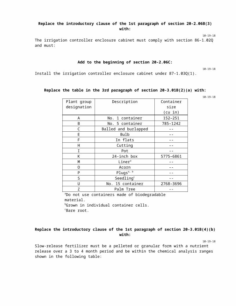
Replace the introductory clause of the 1st paragraph of section 20-2.06B(3) with:10-19-18
The irrigation controller enclosure cabinet must comply with section 86-1.02Q and must:
Add to the beginning of section 20-2.06C:10-19-18
Install the irrigation controller enclosure cabinet under 87-1.03Q(1).

Replace the table in the 3rd paragraph of section 20-3.01B(2)(a) with:10-19-18
Plant group designation
Description Container size(cu in)
A No. 1 container 152–251B No. 5 container 785–1242C Balled and burlapped --E Bulb --F In flats --H Cutting --I Pot --K 24-inch box 5775–6861M Linera --O Acorn --P Plugsa, b --S Seedlingc --U No. 15 container 2768–3696Z Palm Tree --
aDo not use containers made of biodegradable material.bGrown in individual container cells.cBare root.
Replace the introductory clause of the 1st paragraph of section 20-3.01B(4)(b) with:10-19-18
Slow-release fertilizer must be a pelleted or granular form with a nutrient release over a 3 to 4 month period and be within the chemical analysis ranges shown in the following table:
Replace section 20-3.01C(3) with:10-19-18
Water plants as needed to keep the plants in a healthy growing condition.
Replace the 1st paragraph of section 20-4.03G with:10-19-18
Operate the electric automatic irrigation systems, including external weather and other system data inputs required to operate the system in automatic mode, unless otherwise authorized.
10-19-18Delete the 3rd paragraph of section 20-4.03G.
Add to the end of section 20-5.03B(3):10-19-18
If you are ordered to remove existing concrete below ground within the limits of the rock blanket, saw cut the concrete before removal. This work is change order work.
Replace item 1 in the list in the 1st paragraph of section 20-10.03A(3) with:10-19-18
1. Transplanting trees. The work plan must include methods of lifting, transporting, storing, planting, guying, watering and maintaining each tree to be transplanted. Include the root ball size, method of root ball containment, and a maintenance program for each tree.
Add to the end of section 20-10.03C(3):10-19-18
Water transplanted trees immediately after planting and as needed to keep it in a healthy growing condition until contract acceptance.
Add to the end of section 20-10.03C(4):10-19-18
Water existing plants as needed to keep them in a healthy growing condition until contract acceptance.
^^^^^^^^^^^^^^^^^^^^^^^^^^^^^^^^^^^^^^^^^^^^^^^^^^^^^^^^^^^^
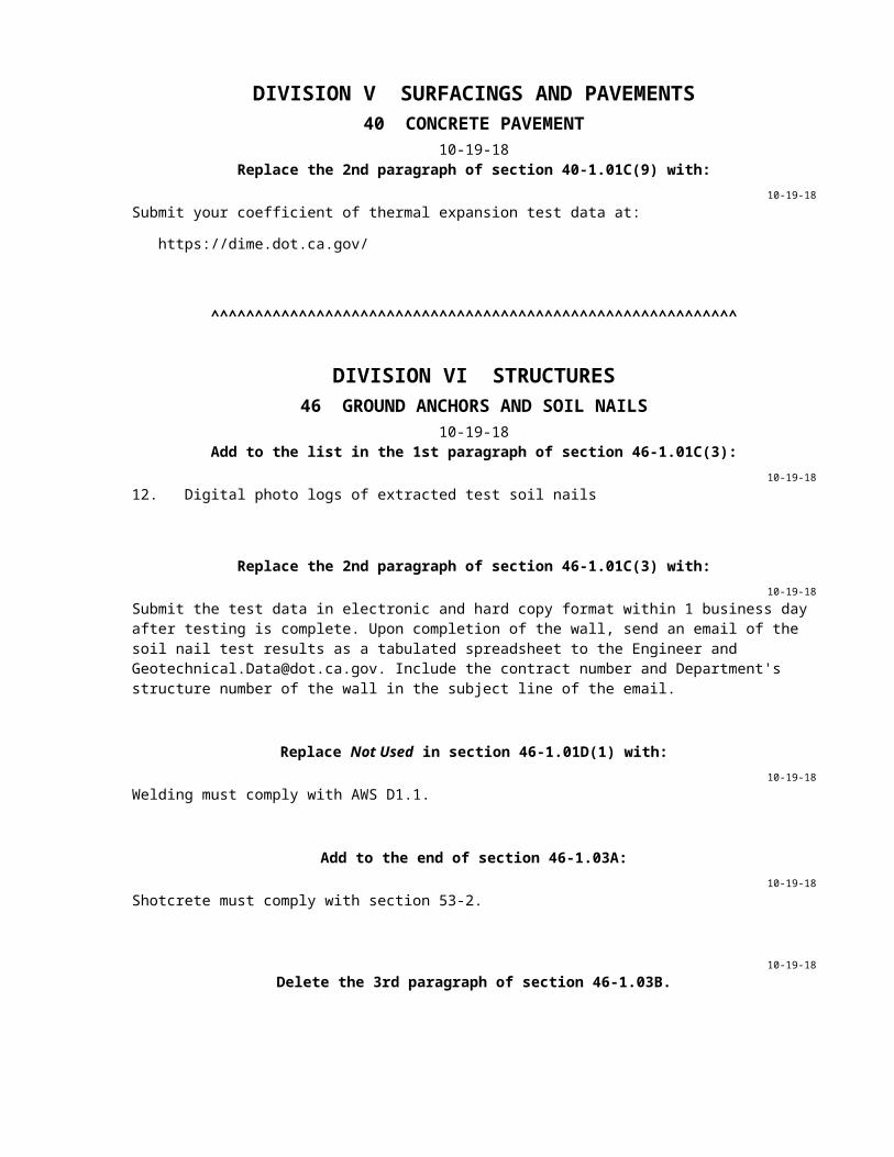
DIVISION V SURFACINGS AND PAVEMENTS40 CONCRETE PAVEMENT
10-19-18Replace the 2nd paragraph of section 40-1.01C(9) with:
10-19-18Submit your coefficient of thermal expansion test data at:
https://dime.dot.ca.gov/
^^^^^^^^^^^^^^^^^^^^^^^^^^^^^^^^^^^^^^^^^^^^^^^^^^^^^^^^^^^^
DIVISION VI STRUCTURES46 GROUND ANCHORS AND SOIL NAILS
10-19-18Add to the list in the 1st paragraph of section 46-1.01C(3):
10-19-1812. Digital photo logs of extracted test soil nails
Replace the 2nd paragraph of section 46-1.01C(3) with:10-19-18
Submit the test data in electronic and hard copy format within 1 business day after testing is complete. Upon completion of the wall, send an email of the soil nail test results as a tabulated spreadsheet to the Engineer and [email protected]. Include the contract number and Department's structure number of the wall in the subject line of the email.
Replace Not Used in section 46-1.01D(1) with:10-19-18
Welding must comply with AWS D1.1.
Add to the end of section 46-1.03A:10-19-18
Shotcrete must comply with section 53-2.

10-19-18Delete the 3rd paragraph of section 46-1.03B.
Replace the 1st sentence in the 2nd paragraph of section 46-2.02B with:10-19-18
The anchorage enclosure and the steel tube and bearing plate of the anchorage assembly must be galvanized steel and comply with sections 55-1.02D(1) and 55-1.02E(1).
Replace item 9 in the list in the 3rd paragraph of section 46-2.02D with:10-19-18
9. Have the physical properties shown in Table 4.1 of Recommendations for Prestressed Rock and Soil Anchors published by the Post-Tensioning Institute
Replace the 4th paragraph of section 46-2.03D with:10-19-18
Immediately after lock-off, perform a lift-off test to verify that the lock-off load has been attained. The lift-off load must be within 10 percent of the specified lock-off load. If necessary adjust the shim thickness to achieve the lock-off load. If the load is not within 10 percent of the specified lock-off load, the anchorage must be reset and another lift-off load reading must be made. Repeat the process until the specified lock-off load is obtained.
Replace the 2nd paragraph of section 46-3.01A with:10-19-18
A soil nail consists of a solid steel bar with an anchorage assembly that is placed in a drilled hole and then grouted.
Replace section 46-3.01D(2)(b)(ii)(1) with:10-19-18
46-3.01D(2)(b)(ii)(1) GeneralDetermine the test load using the following equation:
T = Lb x Qb
where:T = test load, poundsLb = soil nail bonded length, feet, 10 feet minimumQb = test load per unit length of bond, pounds/foot
Replace section 46-3.02A with:10-19-18
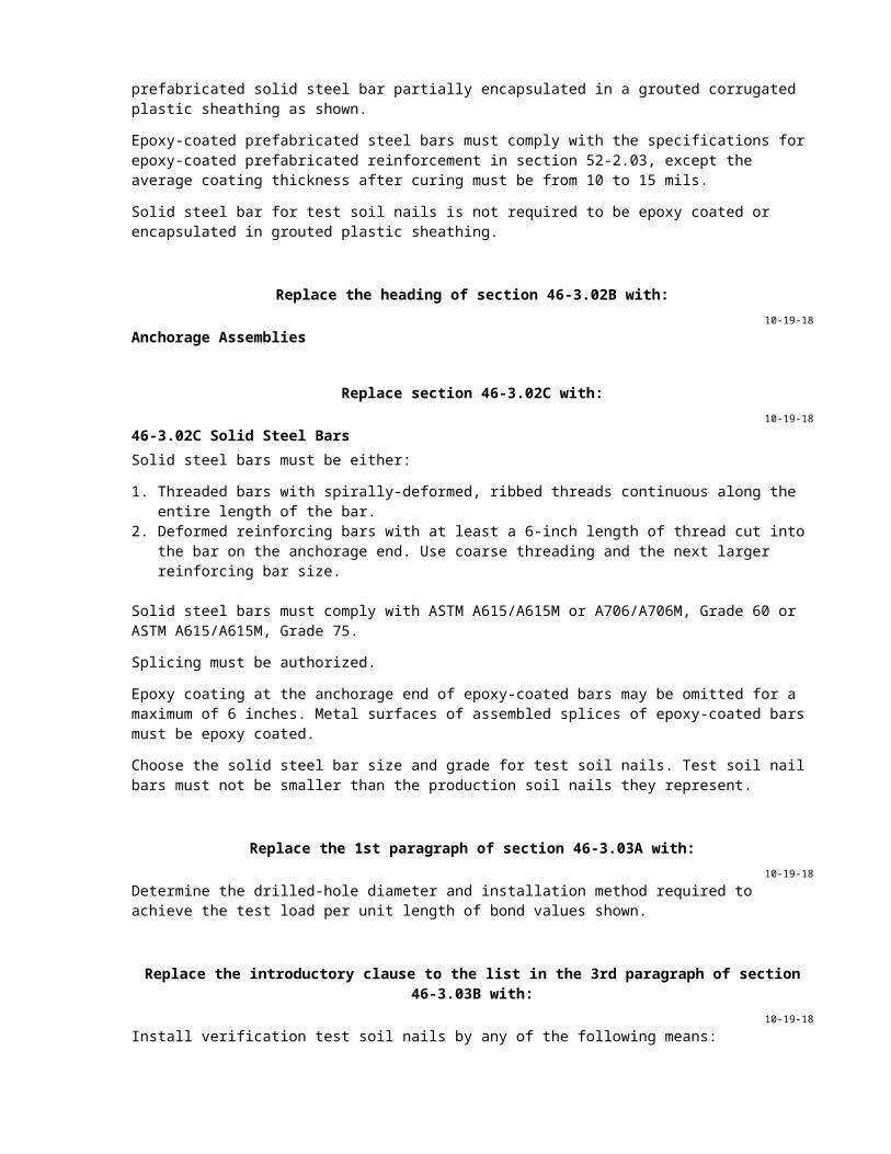
46-3.02A GeneralEach production soil nail must be either a solid steel bar encapsulated full length in a grouted corrugated plastic sheathing or an epoxy-coated prefabricated solid steel bar partially encapsulated in a grouted corrugated plastic sheathing as shown.
Epoxy-coated prefabricated steel bars must comply with the specifications for epoxy-coated prefabricated reinforcement in section 52-2.03, except the average coating thickness after curing must be from 10 to 15 mils.
Solid steel bar for test soil nails is not required to be epoxy coated or encapsulated in grouted plastic sheathing.
Replace the heading of section 46-3.02B with:10-19-18
Anchorage Assemblies
Replace section 46-3.02C with:10-19-18
46-3.02C Solid Steel BarsSolid steel bars must be either:
1. Threaded bars with spirally-deformed, ribbed threads continuous along the entire length of the bar.2. Deformed reinforcing bars with at least a 6-inch length of thread cut into the bar on the anchorage
end. Use coarse threading and the next larger reinforcing bar size.
Solid steel bars must comply with ASTM A615/A615M or A706/A706M, Grade 60 or ASTM A615/A615M, Grade 75.
Splicing must be authorized.
Epoxy coating at the anchorage end of epoxy-coated bars may be omitted for a maximum of 6 inches. Metal surfaces of assembled splices of epoxy-coated bars must be epoxy coated.
Choose the solid steel bar size and grade for test soil nails. Test soil nail bars must not be smaller than the production soil nails they represent.
Replace the 1st paragraph of section 46-3.03A with:10-19-18
Determine the drilled-hole diameter and installation method required to achieve the test load per unit length of bond values shown.
Replace the introductory clause to the list in the 3rd paragraph of section 46-3.03B with:10-19-18
Install verification test soil nails by any of the following means:
Replace the 7th and 8th paragraphs of section 46-3.03B with:10-19-18
Remove each verification and proof test soil nail to 6 inches behind the front face of the shotcrete after testing is complete. Fill the voids with grout.
If ordered, extract verification and proof test soil nails selected by the Engineer. Fill the voids with grout. Photograph the extracted test nails in 5-foot section intervals.
Replace the 3rd paragraph of section 46-3.03C with:10-19-18
Splice the solid steel bar only where shown on the authorized shop drawings or at the end of a soil nail that is ordered to be lengthened.

Replace the 1st sentence in the 7th paragraph of section 46-3.03C with:10-19-18
Hand tighten the nut on the end of the production soil nail bar before shotcrete hardening begins. Ensure the bearing plate is fully seated on the shotcrete.
^^^^^^^^^^^^^^^^^^^^^^^^^^^^^^^^^^^^^^^^
48 TEMPORARY STRUCTURES10-19-18
Add to the end of section 48-1.01:10-19-18
Falsework, temporary supports and jacking support systems must comply with any additional requirements of the railroad company involved.
Add to section 48-2.01B:10-19-18
Falsework release: Lowering of falsework to the point that it no longer supports the loads imposed by the permanent structure, or any element, that the falsework was designed to support during construction.
Falsework removal: Releasing, lowering, and disposing of the falsework.
10-19-18Delete the 7th paragraph of section 48-2.01C(2).
Replace the 4th paragraph of section 48-2.02B(2) with:10-19-18
The assumed horizontal load the falsework bracing system must resist must be the sum of the actual horizontal loads due to equipment, construction sequence or other causes, and a wind loading. The assumed horizontal load in any direction must be at least 2 percent of the total dead load.
Replace the table in the 2nd paragraph of section 48-2.02B(3)(b) with:10-19-18
Quality characteristic RequirementCompression perpendicular to the grain (psi) 450
Compression parallel to the grain (psi) 480,000/(L/d)²;1,600 maximum
Flexural stress 1,800 psi; 1,500 psi maximum for members with a nominal depth of 8 inches or less.
Horizontal shear (psi) 140Axial tension (psi) 1,200Deflection due to concrete loading only 1/240 of span lengthModulus of elasticity (E) (psi) 1.6 x 10⁶
Timber piles (tons) 45NOTES:
L = unsupported length, inchesd = least dimension of a square or rectangular column or the width of a square of equivalent cross-sectional area for round columns, inches
Replace the table in the 3rd paragraph of section 48-2.02B(3)(c) with:10-19-18
Quality characteristic RequirementCompression, flexural (psi) 12,000,000/[(L x d)/(b x t)]a
Deflection due to concrete loading only 1/240 of the spanModulus of elasticity (E) (psi) 30 x 106
NOTES:L = unsupported length, inchesd = least dimension of rectangular columns or the width of a square of equivalent cross-sectional area for round columns, or the depth of beams, inchesb = width of the compression flange, inchest = thickness of the compression flange, inchesFy = specified minimum yield stress in psi
aNot to exceed (1) 22,000 psi for unidentified steel, (2) 22,000 psi for steel complying with ASTM A36/A36M, or (3) 0.6Fy for other identified steel
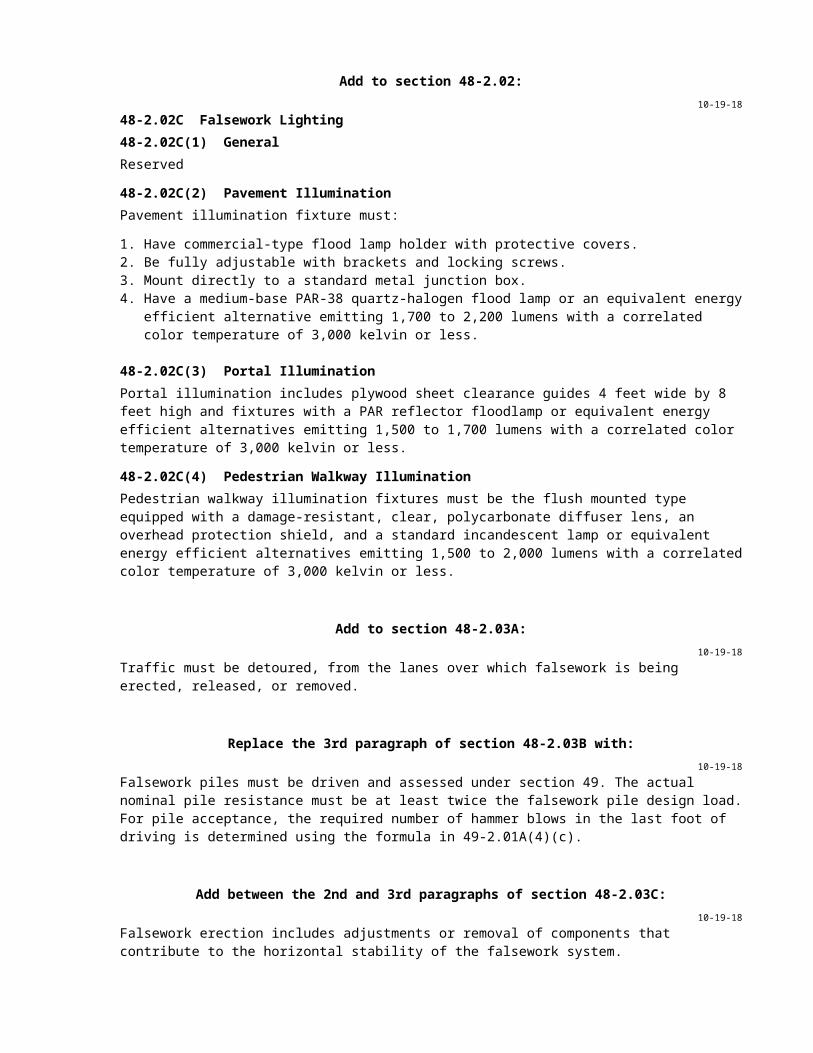
Add to section 48-2.02:10-19-18
48-2.02C Falsework Lighting48-2.02C(1) GeneralReserved
48-2.02C(2) Pavement IlluminationPavement illumination fixture must:
1. Have commercial-type flood lamp holder with protective covers.2. Be fully adjustable with brackets and locking screws.3. Mount directly to a standard metal junction box.4. Have a medium-base PAR-38 quartz-halogen flood lamp or an equivalent energy efficient alternative
emitting 1,700 to 2,200 lumens with a correlated color temperature of 3,000 kelvin or less.
48-2.02C(3) Portal IlluminationPortal illumination includes plywood sheet clearance guides 4 feet wide by 8 feet high and fixtures with a PAR reflector floodlamp or equivalent energy efficient alternatives emitting 1,500 to 1,700 lumens with a correlated color temperature of 3,000 kelvin or less.
48-2.02C(4) Pedestrian Walkway IlluminationPedestrian walkway illumination fixtures must be the flush mounted type equipped with a damage-resistant, clear, polycarbonate diffuser lens, an overhead protection shield, and a standard incandescent lamp or equivalent energy efficient alternatives emitting 1,500 to 2,000 lumens with a correlated color temperature of 3,000 kelvin or less.
Add to section 48-2.03A:10-19-18
Traffic must be detoured, from the lanes over which falsework is being erected, released, or removed.
Replace the 3rd paragraph of section 48-2.03B with:10-19-18
Falsework piles must be driven and assessed under section 49. The actual nominal pile resistance must be at least twice the falsework pile design load. For pile acceptance, the required number of hammer blows in the last foot of driving is determined using the formula in 49-2.01A(4)(c).

Add between the 2nd and 3rd paragraphs of section 48-2.03C:10-19-18
Falsework erection includes adjustments or removal of components that contribute to the horizontal stability of the falsework system.
Replace section 48-2.03D with:10-19-18
48-2.03D RemovalRemove falsework such that portions of falsework not yet removed remain stable at all times.
Falsework release includes blowing sand from sand jacks, turning screws on screw jacks, and removing wedges.
Except for concrete above the deck, do not release falsework supporting any span of a:
1. Simple span bridge before 10 days after the last concrete has been placed2. Continuous or rigid frame bridge before 10 days after the last concrete has been placed:
2.1. In that span2.2. In adjacent portions of each adjoining span for a length equal to one-half of the span where
falsework is to be released3. Simple span, continuous, or rigid frame bridge until the supported concrete has attained a
compressive strength of 2,880 psi or 80 percent of the specified strength, whichever is greater
Do not release falsework for prestressed portions of structures until prestressing steel has been tensioned.
Do not release falsework supporting any span of a continuous or rigid frame bridge until all required prestressing is complete (1) in that span and (2) in adjacent portions of each adjoining span for a length equal to at least one half of the span where falsework is to be released.
Release falsework supporting spans of CIP girders, slab bridges, or culverts before constructing or installing railings or barriers on the spans unless authorized.
Release falsework for arch bridges uniformly and gradually. Start at the crown and work toward the springing. Release falsework for adjacent arch spans concurrently.
Do not release falsework that supports overhangs, deck slabs between girders, or girder stems that slope 45 degrees or more from vertical before 7 days after deck concrete has been placed.
You may release falsework supporting the sides of girder stems that slope less than 45 degrees from vertical before placing deck concrete if you install lateral supports. Lateral supports must be:
1. Designed to resist rotational forces on the girder stem, including forces due to concrete deck placement
2. Installed immediately after each form panel is removed3. Installed before releasing supports for the adjacent form panel
Do not release falsework for bent caps supporting steel or PC concrete girders before 7 days after placing bent cap concrete.
Release falsework for structural members subject to bending as specified for simple span bridges.
Do not release falsework for box culverts and other structures with decks lower than the roadway pavement and span lengths of 14 feet or less until the last placed concrete has attained a compressive strength of 1,600 psi. Curing of the concrete must not be interrupted. Falsework release for other box culverts must comply with the specifications for the release of bridge falsework.
Do not release falsework for arch culverts sooner than 40 hours after concrete has been placed.
Remove falsework piling to at least 2 feet below the original ground or streambed. Remove falsework piling driven within ditch or channel excavation limits to at least 2 feet below the bottom and side slopes of the excavated areas.
Dispose of falsework materials and work debris.
Falsework removal systems employing methods of holding falsework by winches, hydraulic jacks with prestressing steel, HS rods, or cranes must also be supported by an independent support system when the falsework removal system is not actively lowering the falsework at vehicular, pedestrian, or railroad traffic openings.
Bridge deck openings used to facilitate falsework removal activities must be formed with a 6-inch maximum diameter opening. The opening must be located away from the wheel paths.
Clean and roughen openings made in the bridge deck. Fill the deck openings with rapid setting concrete complying with section 60-3.02B(2).
Bridge soffit openings used to facilitate falsework removal activities must be formed with a 5-inch maximum diameter.
Anchor 10-inch-square aluminum or galvanized steel wire, 1/4-inch-mesh hardware cloth with a 0.025- inch minimum wire diameter firmly to the inside of the soffit openings. Construct a 1/2-inch drip groove to the outside of soffit openings.
Falsework removal over roadways with a vertical traffic opening of less than 20 feet must start within 14 days after the falsework is eligible to be released and must be completed within 45 days after it is eligible to be released.
Replace section 48-2.03E with: 10-19-18
48-2.03E Falsework Lighting48-2.03E(1) GeneralProvide lighting to illuminate the pavement, portals, and pedestrian walkways at or under openings in the falsework required for traffic.
Install lighting for pedestrian walkway illumination at all pedestrian openings through or under the falsework.
Design falsework lighting such that required maintenance can be performed with a minimum of inconvenience to traffic. Closing of traffic lanes for routine maintenance is not allowed on roadways with posted speed limits greater than 25 mph.
During the hours of darkness, illuminate:
1. Falsework portals2. Pavement under falsework with portals less than 150 feet apart
Use photoelectric switches to control falsework lighting systems. Pavement under falsework with portals 150 feet or more apart and all pedestrian openings through falsework must be illuminated 24 hours per day.
Aim the lighting fixtures to avoid glare to motorists.
Fasten a Type NMC cable with no. 12 minimum conductors with ground wire to the supporting structure at sufficient intervals to adequately support the cable and within 12 inches from every box or fitting. Use 1/2-inch or larger Type 1 conduit for conductors within 8 feet of ground.
Provide a maximum 20 A fuse for each branch circuit for illumination systems at each bridge location.
Arrange with the service utility to complete service connections for falsework lighting. You pay for energy, line extension, service, and service hookup costs.

48-2.03E(2) Pavement IlluminationInstall a continuous row of fixtures beneath falsework structure with the end fixtures not further than 10 feet inside portal faces. Energize the fixtures immediately after the members supporting them have been erected.
Place the fixtures along the sides of the opening not more than 4 feet behind or 2 feet in front of the roadway face of the temporary railing. Mount the fixtures from 12 to 16 feet above the roadway surface without obstructing the light pattern on the pavement.
48-2.03E(3) Portal IlluminationProvide falsework portal illumination on the side facing traffic. Mount fixtures on the structure directly over each vertical support adjacent to the traveled way, as needed, to uniformly illuminate the exterior falsework beam, the clearance guides, and the overhead clearance sign. Each fixture must be supported approximately 16 feet above the pavement and 6 feet in front of the portal face.
Portal illumination clearance guides must:
1. Be fastened vertically, facing traffic, with the bottom of the panel from 3 to 4 feet above the roadway2. Have the center of the panel located approximately 3 feet horizontally behind the roadway face of the
railing3. Be freshly painted panels for each installation with not less than 2 applications of flat white paint.
Paint testing of painted panels not required.
Portal lighting and clearance guides must be installed on the day the vertical members are erected.
If ordered, repaint the designated areas to improve the general appearance of the painted surfaces. Repainting is change order work.
48-2.03E(4) Pedestrian Walkway IlluminationProvide pedestrian walkway illumination immediately after the overhead protection shield is erected.
Flush mount the fixtures in the overhead protection shield and center them over the passageway at intervals of not more than 15 feet with the end fixtures not more than 7 feet inside the end of the pedestrian openings.
10-19-18Delete the 4th paragraph of section 48-3.01C(2).
Add between the 9th and 10th paragraphs of section 48-3.02B:10-19-18
For bridge removal, the temporary support system must resist the design loads and forces shown. As a minimum, the horizontal load to be resisted in any direction for temporary support shoring and temporary bracing must be (1) the sum of actual horizontal loads due to equipment, construction sequence, or other causes plus an allowance for wind and (2) not less than 5 percent of the total dead load of the structure being removed.
10-19-18Delete the 2nd and 3rd paragraphs of section 48-4.01A.
Replace section 48-4.01C with: 10-19-18
48-4.01C SubmittalsSubmit shop drawings for temporary decking. Include the following:
1. Description, location, and value of all loads if temporary decking is not shown

2. Details of the connection between the temporary decking and the existing or new structure if temporary decking is not shown
3. Storage location of equipment and materials that allows for 1 shift of work and placement of temporary decking within the time allowed
4. Construction sequence and schedule details5. Cure time for concrete to be placed under a steel plate system6. Details for removing temporary decking and restoring the existing structure
If temporary decking is not shown, shop drawings must be signed by an engineer who is registered as a civil engineer in the State.
Replace section 48-4.01D with: 10-19-18
48-4.01D Quality AssuranceIf temporary decking is not shown, the temporary decking design must comply with:
1. The unfactored permit loads, braking force, and HL93 loads except lane load from AASHTO LRFD Bridge Specifications with California Amendments.
2. Section 48-2.02B(3) 3. Live load deflection must not exceed 1/300 of the temporary decking span for the design load.4. Temporary decking must have a uniform surface with a coefficient of friction of at least 0.35 when
measured under California Test 342.5. Steel plate systems must be mechanically connected to the existing structure and adjacent
approaches. If a steel plate spans a joint, the mechanical connection must accommodate at least 50 percent of the movement rating shown for that joint.
6. Must not overstress, induce permanent forces into, or produce cracking in the existing structure.
Replace section 48-4.03 with: 10-19-18
48-4.03 CONSTRUCTIONTemporary decking must consist of one of the following:
1. Steel plate system that spans the incomplete work.2. Falsework with an asphalt concrete surface that spans the incomplete work. Do not use falsework
with an asphalt concrete surface to cover deck concrete that has not cured or to cover partially installed joint materials.
Construct temporary decking under the specifications for falsework in section 48-2 except the first paragraph of section 48-2.03D does not apply.
If there is an elevation difference of more than 1/2 inch between the temporary decking and the adjacent deck, install temporary tapers up to and away from the temporary decking. Construct tapers under section 7-1.03. If the temporary decking does not extend the entire width of the roadway, taper the sides of the temporary decking at a 12:1 (horizontal: vertical) ratio.
Material for temporary tapers must comply with section 60-3.02B(2) or 60-3.04B(2). Cure temporary tapers at least 3 hours before allowing traffic on the temporary decking.
If unanticipated displacements, cracking, or other damage occurs to the existing structure or to any new components installed in or adjacent to the deck, stop work on the deck and perform corrective measures.
Edges of steel plate systems must be in full contact with the existing deck and the adjacent approach slab. If used, shims must be securely attached to the plate.
For falsework with an asphalt concrete cover, asphalt concrete must be at least 3 inches thick and compacted in place.
Do not allow traffic on deck concrete until it has attained the design compressive strength shown.
When temporary decking is no longer needed, remove temporary decking materials and connections from the existing structure as soon as possible. Remove modifications to the existing structure except where permanent alterations are shown.
10-19-18Delete the 4th paragraph of section 48-5.01C.
Replace the 1st paragraph of section 48-5.02B with:10-19-18
The jacking support system must resist the structure dead load and lateral design forces shown, plus any additional loads from jacking equipment and activities. As a minimum, the horizontal load to be resisted in any direction for the jacking support system and temporary bracing must be (1) the sum of actual horizontal loads due to equipment, construction sequence, or other causes plus an allowance for wind as specified in Section 48-2.02B(2) and (2) not less than 2 percent of the total dead load of the structure being jacked. You must determine soil bearing values for support footings. If the jacking support stiffness exceeds the described minimum stiffness, increase the lateral design forces to be compatible with the jacking support lateral stiffness.
Replace the 1st paragraph of section 48-5.03 with:10-19-18
Construct the jacking support system under the specifications for falsework in section 48-2.03.
^^^^^^^^^^^^^^^^^^^^^^^^^^^^^^^^^^^^^^^^
49 PILING10-19-18
Replace the 6th paragraph of section 49-1.01D(4) with:10-19-18
Except for load test piles and anchor piles, drive the 1st production pile in the control zone. Do not install any additional production piles until dynamic monitoring has been performed, and the Engineer provides you with the bearing acceptance criteria curves for any piles represented by the dynamically monitored piles.
Replace the 3rd paragraph of section 49-2.01D with:10-19-18
The payment quantity for furnish piling is the length measured along the longest side of the pile from the specified tip elevation shown to the plane of pile cutoff, except for dynamically monitored piles. For dynamically monitored piles, the payment quantity for furnish piling includes an additional length of 2 times the largest cross-sectional dimension of the pile plus 2 feet.
Add to the end of section 49-2.02A(2):10-19-18
longitudinal weld length: The length of a continuous longitudinal weld.
circumferential weld length: The length of a continuous weld around the circumference of the pipe pile.

spiral weld length: The length of one full 360-degree spiral weld revolution around the circumference of the pipe pile.
Replace the 3rd paragraph of section 49-2.02A(4)(b)(iii)(B) with:10-19-18
For welding performed under AWS D1.1:
1. Perform NDT on 25 percent of each longitudinal, circumferential, or spiral weld length using RT or UT.
2. If repairs are required in a portion of the tested weld:2.1. Perform additional NDT on untested areas on each end of the initial portion tested. The length
of additional NDT on each end must equal 10 percent of the weld length. If it is not possible to perform 10 percent of the weld length on one end, perform the remaining percentage on the other end.
2.2. After this additional 20 percent of NDT is performed, determine and record the total cumulative repair lengths from all NDT for each weld length. If the cumulative weld repair length is equal to or more than 10 percent of the weld length, then perform NDT on the entire weld length.
2.3. Perform NDT on the repaired portion plus 2 inches on each end of the repaired weld excavation.
Replace the 2nd paragraph of section 49-2.02A(4)(b)(iii)(C) with:10-19-18
Perform NDT on 25 percent of the weld length performed by each welder, using RT or UT at locations selected by the Engineer. The Engineer may select several locations on a given splice. The cover pass must be ground smooth at locations to be tested.
Replace the 4th paragraph of section 49-2.02A(4)(b)(iii)(C) with:10-19-18
If repairs are required in a portion of the tested weld:
1. Perform additional NDT on untested areas on each end of the initial portion tested. The length of additional NDT on each end must equal 10 percent of the pipe's outside circumference. If it is not possible to perform 10 percent of the weld length on one end, perform the remaining percentage on the other end.
2. After this additional 20 percent of NDT is performed, determine and record the total cumulative repair lengths from all NDT for each weld length. If the cumulative weld repair length is equal to or more than 10 percent of the pipe's outside circumference, then perform NDT on the entire weld length.
3. Perform NDT on the repaired portion plus 2 inches on each end of the repaired weld excavation.
^^^^^^^^^^^^^^^^^^^^^^^^^^^^^^^^^^^^^^^^
51 CONCRETE STRUCTURES10-19-18
Add to section 51-1.03:10-19-18
51-1.03J Temporary DeckingIf you are unable to complete bridge reconstruction activities before the bridge is to be opened to traffic, furnish and maintain temporary decking under section 48-4 until that portion of the work is complete.

Add between the 5th and 6th paragraphs of section 51-4.03B:10-19-18
Erect steel or PC girders onto the supporting concrete, such as bent caps or abutments, after the concrete attains a compressive strength of 2,880 psi or 80 percent of the specified strength, whichever is greater.
^^^^^^^^^^^^^^^^^^^^^^^^^^^^^^^^^^^^^^^^
53 SHOTCRETE10-19-18
Replace the 1st sentence of section 53-2.01A with:10-19-18
Section 53-2 includes specifications for placing structural shotcrete using the wet-mix process.
Add between the 1st and 2nd paragraphs of section 53-2.01D(4)(b):10-19-18
For soil nail walls, do not core through waler bars.
Add to the beginning of section 53-2.02:10-19-18
Shotcrete must comply with the specifications for concrete in section 90-1.
^^^^^^^^^^^^^^^^^^^^^^^^^^^^^^^^^^^^^^^^
57 WOOD AND PLASTIC LUMBER STRUCTURES10-19-18
Replace the table in the 4th paragraph of section 57-3.02C with:10-19-18
Quality characteristic Test method RequirementDensity of concrete core (kg/m3, min)
ASTM D792 1,762
28-day compressive strength of concrete core (psi, min)
ASTM C579 5,000
Structural strength of shell:Tensile strength, tensile modulus (percent loss)Flexural strength, flexural modulus (percent loss)
ASTM D638
ASTM D790
Less than 10 after UV deterioration test specified
for plastic lumber
Dry film thickness of coating (mils, min)
-- 15
Color change of coating ASTM D4587,Test Cycle 2
No visible color change when tested for 800 hours
Initial adhesion of coating (psi, min) ASTM D4541, Test Method D,
E, or F and Protocol 2
150
Decrease in initial adhesion of coating, decrease (percent)
ASTM D4541, Test Method D,
E, or F and Protocol 2
ASTM D1183,Test Condition Da
No more than 10 following 2 exposure cycles
aUse a low temperature phase at 4 ± 5 °F and high temperature phase at 140 ± 5 °F.
^^^^^^^^^^^^^^^^^^^^^^^^^^^^^^^^^^^^^^^^
59 STRUCTURAL STEEL COATINGS10-19-18
Replace the 2nd paragraph in section 59-1.01D with:10-19-18
Measure coating adhesion strength with a self-aligning adhesion tester under ASTM D4541, Test Method D, E, or F and Protocol 2.
Replace the 2nd paragraph of section 59-1.02C with:10-19-18
Coatings selected for use must comply with the volatile organic compound concentration limits specified for the air quality district where the coating is applied. The undercoats and finish or final coats selected for use must be compatible with each other.
Add after the paragraph of section 59-2.01A(3)(a):10-19-18
If requested by the Engineer, submit documentation from the coating manufacturer verifying the compatibility of the undercoats and finish or final coats selected for use.
^^^^^^^^^^^^^^^^^^^^^^^^^^^^^^^^^^^^^^^^
60 EXISTING STRUCTURES10-19-18
Replace Reserved in section 60-2.02B(1) with:10-19-18
Design criteria for temporary support shoring and temporary bracing must comply with section 48-3.02B.
10-19-18Delete section 60-2.02B(2).
Add to section 60-3.01A:10-19-18
If you are unable to complete bridge reconstruction activities before the bridge is to be opened to traffic, furnish and maintain temporary decking under section 48-4 until that portion of the work is complete.
Replace the 3rd and 4th paragraphs of section 60-3.02C(3) with:10-19-18
Remove asphalt concrete surfacing and membrane seal by cold milling. Do not remove more than 1/2 inch of the existing concrete slab during cold-milling activities.
Add to section 60-3.02C(3):10-19-18
Where a portion of the asphalt concrete surfacing is to remain, saw cut a 2-inch-deep true line along the edge to remain in place before removing asphalt concrete. Remove the asphalt concrete without damaging the surfacing to remain in place.
Replace the 9th paragraph of section 60-3.04B(3)(c) with:10-19-18
Protect the overlay from moisture and do not allow traffic or equipment on the overlay (1) for a minimum of 4 hours cure time after final finishing and (2) until the rebound test results for the final finish show an average reading of at least 28 when tested under ASTM C805. The cure time may be extended if ordered. The rebound test may not be used to reduce the 4-hour cure time of the overlay.
Replace item 2 in the list in the 1st paragraph of section 60-4.06A(4) with:10-19-18
2. 2nd sentence of clause 3.13.2 and the 1st sentence of clause 3.13.3 of AWS D1.5 do not apply.
Replace the 10th paragraph of section 60-4.09B(2)(a) with:10-19-18
Steel parts must comply with ASTM A36/A36M or A576, Grade 1030 and must not be rimmed or capped steel.
^^^^^^^^^^^^^^^^^^^^^^^^^^^^^^^^^^^^^^^^^^^^^^^^^^^^^^^^^^^^

DIVISION VII DRAINAGE FACILITIES66 CORRUGATED METAL PIPE
10-19-18Replace the 1st paragraph in section 66-1.02D with:
10-19-18Coupling bands for corrugated metal pipe must comply with either section 66-1.02D or section 61-2.01D(2)(b).
Replace the 6th paragraph in section 66-1.02D with:10-19-18
Joints for siphons and joints for pipes shown as watertight must be watertight under pressure and all conditions of expansion, contraction, and settlement, and must comply with section 61-2.01D(2)(a) for watertightness.
Replace the 4th paragraph of section 66-2.03 with:10-19-18
Place cement treated structure backfill for slotted corrugated steel pipe as shown and under section 19-3.02F(3) for soil cement beddings. Cover the completed cement treated structure backfill with a curing seal of asphaltic emulsion, Grade SS1 or CSS1.
^^^^^^^^^^^^^^^^^^^^^^^^^^^^^^^^^^^^^^^^^^^^^^^^^^^^^^^^^^^^
DIVISION VIII MISCELLANEOUS CONSTRUCTION80 FENCES
10-19-18Replace the 2nd paragraph of section 80-3.02B with:
10-19-18Posts and braces must comply with the strength requirements in ASTM F1043 for one of the following:
1. Group IA, regular grade, for round pipes2. Group IC, 50,000 psi yield, for round pipes3. Group II-L for roll-formed posts and braces
Replace the list in section 80-4.02B(1)(b) with:10-19-18
1. Comply with ASTM A1064 and have a Class 1 zinc coating complying with ASTM A6412. Be welded or woven galvanized steel wire fabric3. Be made of at least 16-gauge wire4. Be 36 inches wide
Replace the paragraph in section 80-4.02B(2) with:10-19-18
The materials for a temporary desert tortoise fence must comply with section 80-4.02B(1).

Replace the 2nd sentence in the 1st paragraph of section 80-4.02C(2) with:10-19-18
Embed the posts at maximum 10-foot intervals into the ground.
^^^^^^^^^^^^^^^^^^^^^^^^^^^^^^^^^^^^^^^^^^^^^^^^^^^^^^^^^^^^
DIVISION IX TRAFFIC CONTROL DEVICES82 SIGNS AND MARKERS
10-19-18Replace section 82-5.01A with:
10-19-18Section 82-5 includes specifications for fabricating and installing markers, including milepost markers.
Replace the 2nd paragraph in section 82-5.02E with:10-19-18
A target plate for milepost marker or Type L-1 (CA) or Type L-2 (CA) object marker installed on a metal post must be manufactured from an aluminum sheet or zinc-coated steel sheet.
Replace section 82-5.02H with:10-19-18
82-5.02H Milepost MarkersLetters and numerals on a milepost marker must be made with opaque black paint or film. The paint and film must have an equivalent outdoor weatherability as the retroreflective sheeting specified in ASTM D4956. Nonreflective, opaque, black film must be vinyl or acrylic material.
Film for letters and numerals must be computer cut and have pressure-sensitive adhesive.
Replace the 5th paragraph of section 82-5.03 with:10-19-18
Use stencils to paint letters and numerals on milepost markers.
^^^^^^^^^^^^^^^^^^^^^^^^^^^^^^^^^^^^^^^^
84 MARKINGS10-19-18
Replace section 84-2 with:10-19-18
84-2 TRAFFIC STRIPES AND PAVEMENT MARKINGS84-2.01 GENERAL84-2.01A SummarySection 84-2 includes specifications for applying traffic stripes and pavement markings.
Traffic stripes and pavement markings must comply with ASTM D6628 for daytime and nighttime color.
Retroreflectivity must be measured under ASTM E1710 and the sampling protocol specified in ASTM D7585.

84-2.01B Definitionspavement marking: Transverse marking such as (1) a limit line, (2) a stop line, or (3) a word, symbol,
shoulder, parking stall, or railroad-grade-crossing marking.
traffic stripe: Longitudinal centerline or lane line used for separating traffic lanes in the same direction of travel or in the opposing direction of travel or a longitudinal edge line marking the edge of the traveled way or the edge of a lane at a gore area separating traffic at an exit or entrance ramp. A traffic stripe is shown as a traffic line.
84-2.01C SubmittalsFor each lot or batch of traffic stripe material, primer, and glass beads, submit:
1. Certificate of compliance, including the material name, lot or batch number, and manufacture date2. METS notification letter stating that the material is authorized for use, except for thermoplastic and
primer3. SDS4. Manufacturer’s Instructions
For each lot or batch of thermoplastic, submit a manufacturer's certificate of compliance and the following test results from the California Test 423:
1. Brookfield Thermosel viscosity2. Hardness3. Yellowness index, white only4. Daytime luminance factor5. Yellow color, yellow only6. Glass bead content7. Binder content
The date of the test must be within 1 year of use.
Submit test results for each lot of beads specifying the EPA test methods used and tracing the lot to the specific test sample. The testing for lead and arsenic content must be performed by an independent testing laboratory.
Submit the thermoplastic test stripe to the Engineer.
Submit the retroreflectivity test result within 5 days of testing the traffic stripes and pavement markings. The data must include the retroreflectivity, time, date, and GPS coordinates for each measurement.
84-2.01D Quality Assurance84-2.01D(1) GeneralReserved
84-2.01D(2) Quality ControlBefore starting permanent application of methyl methacrylate and two component paint traffic stripes and pavement markings, apply a test stripe on roofing felt or other suitable material in the presence of the Engineer. The test stripe section must be at least 50 feet in length.
Upon request, apply a thermoplastic test stripe on suitable material in the presence of the Engineer during the application of thermoplastic traffic stripes or markings. The test stripe must be at least 1 foot in length.
Remove loose glass beads before measuring the retroreflectivity. Obtain authorization to proceed with the application of traffic stripes and pavement markings.
Within 30 days of application, test the traffic stripes and pavement markings under the test methods and frequencies shown in the following table:

Traffic Stripe Testing FrequencyQuality characteristic Test method Minimum sampling and testing frequency
Initial retroreflectivity (min, mcd·m-2·lx-1)WhiteYellow
ASTM E1710 ASTM D7585a
aUse the referee evaluation protocol for project length less than 10 miles. For project lengths greater than or equal to 10 miles, add one evaluation for every additional mile.
Verify the glass bead application rate by stabbing the glass bead tank with a calibrated rod.
84-2.01D(3) Department AcceptanceThe Engineer will perform a nighttime, drive-through, visual inspection of the retroreflectivity of the traffic stripes and pavement markings and notify you of any locations with deficient retroreflectivity. Test the retroreflectivity of the deficient areas to confirm striping and pavement markings meets the requirements.
The thermoplastic test stripe will be tested for yellow color, daytime luminance factor, and yellowness index requirements by METS.
84-2.02 MATERIALS84-2.02A GeneralReserved
84-2.02B Glass BeadsEach lot of glass beads must comply with EPA Test Method 3052 and 6010B or 6010C. Glass beads must contain less than 200 ppm each of arsenic and lead.
Type 1 glass beads must comply with AASHTO M 247.
Type 2 glass beads must comply with AASHTO M 247. At least 75 percent of the beads by count must be true spheres that are colorless and do not exhibit dark spots, air inclusions, or surface scratches when viewed under 20X magnification.
High-performance glass beads must be on the Authorized Material List for high-performance glass beads.
Large-gradation glass beads must be on the Authorized Material List for two component traffic paint.
Glass beads for methyl methacrylate must be on the Authorized Material List for methyl methacrylate traffic striping and pavement marking.
Glass beads for paint must comply with State Specification 8010-004.
Glass beads must be surface treated, according to the bead and the material manufacturer’s instructions, to promote adhesion with the specified material.
84-2.02C ThermoplasticThermoplastic must comply with State Specification PTH-02HYDRO, or PTH-02ALKYD.
Sprayable thermoplastic must comply with State Specification PTH-02SPRAY.
Each lot or batch of thermoplastic must be tested under California Test 423.
84-2.02D Methyl MethacrylateMethyl methacrylate traffic paint must:
1. Be on the Authorized Material List for methyl methacrylate traffic striping and pavement marking2. Be Category 2
84-2.02E Traffic Striping and Pavement Marking TapeTraffic striping and pavement marking tape must be on the Authorized Material List for signing and delineation materials.
White tape must be have an initial retroreflectivity of a minimum 700 mcd/m2.

Yellow tape must be have an initial retroreflectivity of a minimum 500 mcd/m2.
When contrast is required for traffic stripping and pavement marking tape, the tape must be pre-formed and retroreflective, consisting of a white film with retroreflective beads and a contrasting black film border. The contrasting black border must be a nonreflective film bonded on each side of the white film to form a continuous roll. Each black border must be a minimum of 2 inches wide. The width of the tape must be at least 4 inches wider than the stripe width.
84-2.02F Two-Component PaintTwo-component traffic paint must be on the Authorized Material List for two component traffic paint.
84-2.02G PaintPaint must comply with the requirements shown in following table:
Paint SpecificationsPaint type Color Specification
Waterborne traffic line White, yellow, and black State Specification PTWB-01R2Waterborne traffic line for the international symbol of accessibility and other curb markings
Blue, red, and green Federal Specification TT-P-1952E
84-2.02H–84-2.02L Reserved84-2.03 CONSTRUCTION84-2.03A GeneralEstablish the alignment for traffic stripes and the layouts for pavement markings with a device or method that will not conflict with other traffic control devices.
Protect existing retroreflective pavement markers during work activities.
Remove existing pavement markers that are coated or damaged by work activities and replace with an equivalent marker on the Authorized Material List for signing and delineation materials.
A completed traffic stripe or pavement marking must:
1. Have well defined edges2. Be uniform3. Be free from runs, bubbles, craters, drag marks, stretch marks, and debris
A completed traffic stripe must:
1. Be straight on a tangent alignment2. Be a true arc on a curved alignment3. Not deviate from the width shown by more than:
3.1. 1/4 inch on a tangent alignment3.2. 1/2 inch on a curved alignment
The length of the gaps and individual stripes that form a broken traffic stripe must not deviate by more than 2 inches from the lengths shown. The gaps and stripes must be uniform throughout the entire length of the traffic stripe.
Protect newly placed traffic stripes and pavement markings from traffic and work activities until the traffic stripes and pavement markings are dry or hard enough to bear traffic.
Use mechanical methods to remove dirt, contaminants, and loose material from the pavement surface before applying the traffic stripe or pavement marking.
Use abrasive blast cleaning to remove laitance and curing compound from the surface of new concrete pavement before applying the traffic stripe or pavement marking.
Construct recesses as shown in the following table:

Recess Depth Requirements
MaterialRequirement
Depth (mils) Depth (in)Thermoplastic 375 3/8Two component traffic paint 250 1/4Methyl methacrylate traffic paint 250 1/4
Construct recesses for double traffic stripes in a single pass.
Before applying the traffic stripes and pavement markings:
1. Allow wet ground recesses to dry a minimum of 24 hours2. Remove all powdery residue from dry recess3. Keep the recesses dry and free from debris
Apply traffic stripes and pavement markings before the end of the same work shift.
84-2.03B Application of Traffic Stripes and Pavement Markings84-2.03B(1) GeneralApply material for a pavement marking with a stencil or a preformed marking.
Immediately remove drips, overspray, improper markings, or material tracked by traffic, using an authorized method.
Apply a traffic stripe or a pavement marking only to a clean, dry surface during a period when the pavement surface temperature is above 50 degrees F.
Apply traffic stripe or pavement marking and glass beads in a single pass. You may apply the glass beads by hand on pavement markings.
Embed glass beads to a depth of 1/2 their diameters.
Distribute glass beads uniformly on traffic stripe and pavement markings.
Glass beads with integral color must match the color of the stripe or pavement marking.
Apply glass beads with two separate applicator guns when two gradations are specified.
Allow enough overlap distance between new and existing striping patterns to ensure continuity at the start and end of the transition.
The retroreflectivity of applied traffic stripes and pavement markings must comply with the requirements shown in the following table:
Retroreflectivity RequirementsTraffic stripe material White (min, mcd·m-2·lx-1) Yellow (min, mcd·m-2·lx-1)
Paint 250 125Thermoplastic 250 125Thermoplastic with wet night enhanced visibility
700 500
Two component 250 125Methyl methacrylate 500 300Tape 700 500
84-2.03B(2) Thermoplastic 84-2.03B(2)(a) GeneralApply primer or surface preparation adhesive under the manufacturer's instructions:
1. To all roadway surfaces except for asphaltic surfaces less than 6 months old2. At a minimum rate of 1 gallon per 300 square feet

3. To allow time for the thermoplastic primer to dry and become tacky before application of the thermoplastic
Do not thin the primer.
Preheat thermoplastic using preheaters with mixers having a 360-degree rotation.
Apply thermoplastic in a single uniform layer by spray or extrusion methods.
Completely coat and fill voids in the pavement surface with the thermoplastic.
Apply recessed thermoplastic at a thickness so that the top is 0 to 1/16 inch below the pavement surface.
84-2.03B(2)(b) Extruded Thermoplastic Apply extruded thermoplastic at a temperature of 400 to 425 degrees F or as recommended by the manufacturer.
Apply extruded thermoplastic for a traffic stripe at a rate of at least 0.36 lb of thermoplastic per foot of 6-inch-wide solid stripe. The applied traffic stripe must be at least 0.060 inch thick.
Apply extruded thermoplastic pavement markings at a thickness from 0.100 to 0.150 inch.
Apply Type 2 glass beads to the surface of the molten thermoplastic at a rate of at least 8 lb of beads per 100 sq ft.
84-2.03B(2)(c) Sprayable ThermoplasticApply sprayable thermoplastic at a temperature of 350 to 400 degrees F.
Apply sprayable thermoplastic for a traffic stripe at a rate of at least 0.24 lb of thermoplastic per foot of 6-inch-wide solid stripe. The applied stripe must be at least 0.040 inch thick.
84-2.03B(2)(d) Thermoplastic with Enhanced Wet-Night VisibilityApply a thermoplastic traffic stripe or pavement marking with enhanced wet-night visibility in a single pass and in the following order:
1. Uniform layer of extruded thermoplastic2. Layer of high-performance glass beads3. Layer of Type 2 glass beads
Apply thermoplastic with enhanced wet-night visibility at a maximum speed of 8 mph.
Apply thermoplastic with enhanced wet-night visibility for a traffic stripe at a rate of at least 0.47 lb of thermoplastic per foot of 6-inch-wide solid stripe. The applied stripe must be at least 0.090 inch thick.
Apply thermoplastic with enhanced wet-night visibility for a pavement marking at a rate of at least 1.06 lb of thermoplastic per square foot of marking. The applied pavement marking must be at least 0.100 inch thick.
Apply high-performance glass beads at a rate of at least 6 lb of glass beads per 100 sq ft of stripe or marking. Apply Type 2, glass beads at a rate of at least 8 lb of glass beads per 100 sq ft of stripe or marking.
84-2.03B(3) Methyl MethacrylateApply the methyl methacrylate when the pavement surface and atmospheric temperatures are from 40 to 104 degrees F.
Apply methyl methacrylate paint at a minimum thickness of 0.090 inch.
Apply recessed methyl methacrylate paint at a minimum thickness of 0.200 inch.
Apply the glass beads recommended by the methyl methacrylate manufacturer.
84-2.03B(4) Traffic Striping and Pavement Marking TapeDo not use traffic stripe and pavement marking tape on existing open graded friction course or chip seal.

Prepare pavement surface and use primer under the traffic tape manufacturer’s written instructions. Apply tape to clean and dry pavement surface. Roll or tamp the traffic tape in place.
84-2.03B(5) Two-Component PaintApply a two-component painted traffic stripe or pavement marking in a single pass and in the following order:
1. Coat of two-component paint2. Application of large gradation glass beads recommended by the two-component paint manufacturer3. Application of Type 1 glass beads
Apply two-component paint when the pavement surface temperature is above 39 degrees F and the atmospheric temperature is above 36 degrees F. The temperature of the paint must comply with the paint manufacturer's instructions.
Apply two-component paint and glass beads at a maximum speed of 10 mph.
Apply large-gradation glass beads at a minimum rate of 11.7 lb of beads per gallon of paint.
Apply Type 1 glass beads at a minimum rate of 8.3 lb of beads per gallon of paint.
Apply two-component paint for the traffic stripes and pavement markings at the thickness and application rates shown in the following table:
Type of pavement Stripe thickness(min, inch)
Application rate(min, sq ft/gal)
HMA open graded/chip seal 0.025 64HMA dense graded 0.020 80Concrete 0.020 80
Apply recessed two-component paint at a thickness between 0.020 and 0.025 inch.
84-2.03B(6) PaintDo not apply paint if:
1. Fresh paint could become damaged by rain, fog, or condensation2. Atmospheric temperature could drop below 50 degrees F during the drying period
Do not thin paint.
Use mechanical means to paint traffic stripes and pavement markings and to apply glass beads for traffic stripes.
The striping machine must be capable of superimposing successive coats of paint on the 1st coat and on existing stripes at a minimum speed of 5 mph.
Where the configuration or location of a traffic stripe is such that the use of a striping machine is not practicable, you may apply the traffic paint and glass beads by other methods and equipment if authorized.
Apply traffic stripes and pavement markings in 1 coat on existing pavement surfaces, at an approximate rate of 107 sq ft/gal.
Apply traffic stripes and pavement markings in 2 coats on a new pavement surface. The 1st coat of paint must be dry before applying the 2nd coat.
Apply 2-coat paint at the approximate rate of 215 sq ft/gal for each coat.
Paint a 1-coat, 3-inch-wide black stripe between the two 6-inch-wide yellow stripes of a double traffic stripe. If the two 6-inch-wide yellow stripes are applied in 2 coats, apply the black stripe concurrently with the 2nd coat of the yellow stripes.
On 2-lane highways:
1. If the 1st coat of the centerline stripe is applied in the same direction as increasing post miles, use the right-hand spray gun of the 3 spray guns to apply a single yellow stripe
2. If the 1st coat of the centerline stripe is applied in the same direction as decreasing post miles, use the left-hand spray gun of the 3 spray guns to apply a single yellow stripe
3. Apply the 2nd coat of centerline striping in the opposite direction of the 1st coat
Apply glass beads at an approximate rate of 5 lb of beads per gallon of paint.
Verify the application rate of paint by stabbing the paint tank with a calibrated rod. If the striping machine has paint gauges, the Engineer may measure the volume of paint using the gauges instead of stabbing the paint tank with a calibrated rod.
84-2.03B(7) Contrast StripingContrast striping consists of black striping placed on each side or end of a white stripe.
You may use permanent tape instead of paint or thermoplastic.
Apply contrast stripe paint in one coat.
Do not use glass beads or other reflective elements in contrast striping material.
84-2.03B(7)–84-2.03B(10) Reserved84-2.04 PAYMENTThe payment quantity for a traffic stripe is the length measured along the line of the traffic stripe without deductions for gaps in the broken traffic stripe.
The payment quantity for a pavement marking is the area covered.
A double traffic stripe consisting of two-6-inch-wide yellow stripes are measured as 2 traffic stripes except for painted traffic stripes and sprayable thermoplastic traffic stripes.
A double sprayable thermoplastic traffic stripe consisting of two 6-inch-wide yellow stripes are measured as single traffic stripe.
A double painted traffic stripe consisting of two 6-inch-wide yellow stripes separated by a 3-inch-wide black stripe is measured as a single traffic stripe.
The payment quantity for contrast striping is the length measured along the line of the traffic stripe without deductions for gaps in the broken traffic stripe.
Replace section 84-9 with:10-19-18
84-9 EXISTING MARKINGS84-9.01 GENERAL84-9.01A SummarySection 84-9 includes specifications for removing existing markings.
Work performed on existing markings must comply with section 15.
84-9.01B DefinitionsReserved
84-9.01B SubmittalsSubmit your proposed method for removing traffic stripes and pavement markings at least 7 days before starting the removal work. Allow 2 business days for the review.
84-9.02 MATERIALSNot Used

84-9.03 CONSTRUCTION84-9.03A GeneralRemove existing traffic stripes before making any changes to the traffic pattern.
Remove existing traffic stripes and pavement markings before applying the following materials:
1. Traffic stripe and pavement marking tape2. Two component traffic stripes and pavement markings3. Methyl methacrylate traffic stripes and pavement markings
Remove contrast treatment, traffic stripes and pavement markings, including any paint in the gaps, by methods that do not remove pavement to a depth of more than 1/8 inch.
Remove pavement markings such that the old message cannot be identified. Make any area removed by grinding rectangular. Water must not puddle in the ground areas. Fog seal ground areas on asphalt concrete pavement.
Sweep up or vacuum any residue before it can (1) be blown by traffic or wind, (2) migrate across lanes or shoulders, or (3) enter a drainage facility.
84-9.03B Remove Traffic Stripes and Pavement Markings Containing LeadReserved
84-9.03C–84-9.03J Reserved84-9.04 PAYMENTThe payment quantity for remove traffic stripe is the measured length multiplied by:
1. 0.67 for a single 4-inch-wide traffic stripe2 1.34 for a single 8-inch-wide traffic stripe3. 2 for a double traffic stripe
The payment quantity for remove traffic stripe does not include the gaps in broken traffic stripes. Payment for removal of paint evident in a gap is included in the payment for remove traffic stripe of the type involved.
If no bid item is shown on the Bid Item List for remove pavement marking, remove pavement marking is paid for as remove traffic stripe of the types shown in the Bid Item List and the payment quantity for 1 square foot of pavement marking is 3 linear feet.
^^^^^^^^^^^^^^^^^^^^^^^^^^^^^^^^^^^^^^^^^^^^^^^^^^^^^^^^^^^^
DIVISION X ELECTRICAL WORK86 GENERAL
10-19-18Replace section 86-1.01B with:
10-19-1886-1.01B Definitionsaccessible pedestrian signal: Accessible pedestrian signal as defined in the California MUTCD.
accessible walk indication: Activated audible and vibrotactile action during the walk interval.
actuation: Actuation as defined in the California MUTCD.
ambient sound level: Background sound level in dB at a given location.
ambient sound sensing microphone: Microphone that measures the ambient sound level in dB and automatically adjusts the accessible pedestrian signal speaker's volume.

audible speech walk message: Audible prerecorded message that communicates to pedestrians which street has the walk interval.
CALiPER: Commercially Available LED Product Evaluation and Reporting. A U.S. Department of Energy program that individually tests and provides unbiased information on the performance of commercially available LED luminaires and lights.
controller assembly: Assembly for controlling a system's operations, consisting of a controller unit and auxiliary equipment housed in a waterproof cabinet.
controller unit: Part of the controller assembly performing the basic timing and logic functions.
correlated color temperature: Absolute temperature in kelvin of a blackbody whose chromaticity most nearly resembles that of the light source.
detector: Detector as defined in the California MUTCD.
electrolier: Assembly of a lighting standard and luminaire.
flasher: Device for opening and closing signal circuits at a repetitive rate.
illuminance gradient: Ratio of the minimum illuminance on a 1-foot square of sign panel to that on an adjacent 1-foot square of sign panel.
inductive loop detector: Detector capable of being actuated by an inductance change caused by a vehicle passing or standing over the loop. An inductive loop detector includes a loop or group of loops installed in the roadway and a lead-in cable installed and connected inside a controller cabinet.
junction temperature: Temperature of the electronic junction of the LED device. The junction temperature is critical in determining photometric performance, estimating operational life, and preventing catastrophic failure of the LED.
L70: Extrapolated life in hours of the luminaire when the luminous output depreciates 30 percent from the initial values.
lighting standard: Pole and mast arm supporting the luminaire.
link: Part of a system which provides a data connection between a transmitter and receiver.
LM-79: Test method from the Illumination Engineering Society of North America specifying the test conditions, measurements, and report format for testing solid state lighting devices, including LED luminaires.
LM-80: Test method from the Illumination Engineering Society of North America specifying the test conditions, measurements, and report format for testing and estimating the long-term performance of LEDs for general lighting purposes.
luminaire: Assembly that houses the light source and controls the light emitted from the light source.
mid-span access method: Procedure in which fibers from a single buffer tube are accessed and spliced to a multi buffer tube cable without cutting the unused fibers in the buffer tube, or disturbing the remaining buffer tubes in the cable.
National Voluntary Laboratory Accreditation Program: U.S. Department of Energy program that accredits independent testing laboratories.
optical time domain reflectometer: Fiber optic test equipment that is used to measure the total amount of power loss between two points and over the corresponding distance. It provides a visual and printed display of the relative location of system components such as fiber sections, splices and connectors as well as the losses that are attributed to each component and or defects in the fiber.
pedestrian change interval: Pedestrian change interval as defined in the California MUTCD.
powder coating: Coating applied electrostatically using exterior-grade, UV-stable, polymer powder.
power factor: Ratio of the real power component to the complex power component.

power meter: Portable fiber optic test equipment that, when coupled with a light source, is used to perform end-to-end attenuation testing. Its display indicates the amount of power injected by the light source at the designed wavelength of the system under testing that arrives at the receiving end of the link.
pretimed controller assembly: Assembly operating traffic signals under a predetermined cycle length.
programming mechanism: Device to program the accessible pedestrian signal operation.
pull box: Box with a cover that is installed in an accessible place in a conduit run to facilitate the pulling in of wires or cables.
push button information message: Push button information message as defined in the California MUTCD.
push button locator tone: Push button locator tone as defined in the California MUTCD.
segment: Continuous cable terminated by 2 splices, 2 connectors or 1 splice and 1 connector.
signal face: Signal face as defined in the California MUTCD.
signal head: Signal head as defined in the California MUTCD.
signal indication: Signal indication as defined in the California MUTCD.
signal section: Signal section as defined in the California MUTCD.
signal standard: Pole with or without mast arms carrying 1 or more signal faces.
street side lumens: Lumens from a luminaire directed to light up areas between the fixture and the roadway, such as traveled ways and freeway lanes.
surge protection device: Subsystem or component that protects equipment against short-duration voltage transients in power line.
total harmonic distortion: Ratio of the rms value of the sum of the squared individual harmonic amplitudes to the rms value of the fundamental frequency of a complex waveform.
traffic-actuated controller assembly: Assembly for operating traffic signals under the varying demands of traffic as registered by detector actuation.
traffic phase: Traffic phase as defined in the California MUTCD.
vehicle: Vehicle as defined in the California Vehicle Code.
vibrotactile pedestrian device: Vibrotactile pedestrian device as defined in the California MUTCD.
10-19-18Delete the 9th and 10th paragraphs of section 86-1.01C(1).
Replace section 86-1.01C(3) with:10-19-18
86-1.01C(3) LuminairesSubmit for a luminaire:
1. Maximum power in watts2. Maximum designed junction temperature3. Heat sink area in square inches4. Designed junction-to-ambient thermal resistance calculation with thermal resistance components
clearly defined5. L70 in hours when extrapolated for the average nighttime operating temperature6. Life expectancy based on the junction temperature

7. Manufacturer's data sheet for the power supply, including the rated life
Submit the manufacturer's QC test data for luminaires as an informational submittal.
Replace section 86-1.01C(4) with:10-19-18
86-1.01C(4) Reserved
Replace the 8th paragraph of section 86-1.02B(1) with:10-19-18
High density polyethylene for innerduct must:
1. Comply with ASTM D3485, D3035, D2239, and D2447, and NEMA TC7 and TC22. Have a minimum tensile yield strength of 3300 psi under ASTM D6383. Have a density of 59.6187 lb/ft3 ± 0.3121 lb/in3 under ASTM D1505
Replace the 4th paragraph of section 86-1.02C(1) with:10-19-18
The cover marking must include CALTRANS and one of the following:
1. SERVICE for service circuits between a service point and service disconnect2. SERVICE IRRIGATION for circuits from a service equipment enclosure to an irrigation controller3. SERVICE BOOSTER PUMP for circuits from a service equipment enclosure to the booster pump4. TDC POWER for circuits from a service equipment enclosure to telephone demarcation cabinet5. LIGHTING for a lighting system6. SIGN ILLUMINATION for a sign illumination system7. SIGNAL AND LIGHTING for a signal and lighting system8. RAMP METER for a ramp metering system9. TMS for a traffic monitoring station10. FLASHING BEACON for a flashing beacon system11. CMS for a changeable message sign system12. INTERCONNECT for an interconnect conduit and cable system13. FIBER OPTIC for fiber optic cable system14. ELECTRICAL SYSTEMS if more than one system is shared in the same pull box
10-19-18Delete the 3rd paragraph of section 86-1.02C(2).
Replace the 1st and 2nd paragraphs of section 86-1.02C(3) with:10-19-18
A traffic pull box and cover must comply with AASHTO HS20-44 and load tested under AASHTO M 306.
The frame must be anchored to the box with 2-1/4-inch-long concrete anchors with a 1/4 inch diameter. A no. 3-1/2(T) pull box must have 4 concrete anchors, one placed in each corner. No. 5(T) and no. 6(T) pull boxes must have 6 concrete anchors, one placed in each corner and one near the middle of each of the longer sides.

Replace section 86-1.02C(4)(b) with:10-19-18
86-1.02C(4)(b) Tamper-Resistant Nontraffic Pull Box86-1.02C(4)(b)(i) GeneralA tamper resistant nontraffic pull box must include a pull box with one of the following:
1. Anchored cover2. Lockable cover3. Pull box insert
86-1.02C(4)(b)(ii) Anchored CoverThe anchored cover must:
1. Be of 1/2-inch-thick mild steel, hot dip galvanized, post fabrication.2. Be hot dip galvanized after manufacturing with spikes removed from the galvanized surfaces.3. Have a center space for a top lock nut that must be torqued to 200 ft-lb.4. Have a center opening for a stainless steel threaded cap to cover the lock nut.5. Weigh a minimum of 85 lb.6. Include an all-around security skirt of 1/4-inch thick steel. The skirt must be sized to encase a
nontraffic pull box or sized to fit within a traffic pull box.7. Be welded to the skirt.
86-1.02C(4)(b)(iii) Lockable CoverThe lockable cover must:
1. Be manufactured from minimum 3/16-inch-thick galvanized steel or a polymer of minimum strength equal to 3/16 inch steel.
2. Be secured to the pull box with a locking mechanism of equal or greater strength than the manufactured material.
3. Have 1/2-by-2-inch slot holes for lifting.4. Have dimensions complying with one of the following:
4.1. Department's standards for pull box covers as shown if the lockable cover is secured to the inside lip of the pull box.
4.2. Department's standards for the length and width as shown for pull box covers if the lockable cover is secured to the top of the pull box.
86-1.02C(4)(b)(iv) Pull Box InsertThe pull box insert must:
1. Be made of minimum 3/16-inch-thick or 10 gauge mild hot-dipped galvanized steel2. Have a minimum of 2 mounting brackets that rest under the side or end wall3. Be lockable with a padlock having a minimum 3/8-inch shackle4. Have dimensions complying with the Department's standards for the length and width as shown for
pull box covers
10-19-18Delete section 86-1.02C(4)(d).
10-19-18Delete section 86-1.02C(4)(e).
10-19-18Delete section 86-1.02C(4)(f).

Replace section 86-1.02D(3) with:10-19-18
86-1.02D(3) Warning TapeWarning tape must be orange color polyolefin film, minimum elongation of 500 percent before breakage, water and corrosion resistant, and comply with requirements shown in the following table:
Warning Tape Requirements
Quality characteristic RequirementThickness (min, mil) 4Width (in) 4Tensile strength of material (min, psi)
2800
Message spacing intervals (ft)
3
The warning tape must have a printed message that reads: CAUTION: CALTRANS FACILITIES BELOW.
The printed text height and color must be 1 inch, black color text over bright orange background.
Replace the 2nd paragraph of section 86-1.02E with:10-19-18
Each sensor must:
1. Have a dissipation factor less than 0.04 nF when measured in the 20 nF range2. Have resistance greater than 20 Megaohms3. Be 1/4 inch wide by 6 feet long by 1/16 inch thick4. Have a RG-58C/U coaxial screen transmission cable, jacketed with high-density polyethylene, rated
for direct burial and resistant to nicks and cuts5. Operate over a temperature range from -40 to 160 degrees F6. Have a signal to noise ratio equal to or greater than 10 to 17. Have an output signal of a minimum 250 mV ± 20 percent for a wheel load of 400 lb at 55 mph and
70 degrees F8. Have an insulation resistance greater than 500 MΩ9. Have a life cycle of a minimum 25 million equivalent single axle loadings
Replace section 86-1.02F(1) with:10-19-18
86-1.02F(1) GeneralConductors and cables must be clearly and permanently marked the entire length of their outer surface with:
1. Manufacturer's name or trademark2. Insulation-type letter designation3. Conductor size4. Voltage5. Number of conductors for a cable
The minimum insulation thickness and color code requirements must comply with NEC.
Replace the 2nd paragraph of section 86-1.02F(2)(a) with:10-19-18
Conductors must be identified as shown in the following table:

Conductor Identification
CircuitSignal phase or
function
IdentificationCopper
sizeInsulation color Band
symbolsBase Stripea

Signals (vehicle)a,b
2, 6 Red, yellow, brown
Black 2, 6 14
4, 8 Red, yellow, brown
Orange 4, 8 14
1, 5 Red, yellow, brown
None 1, 5 14
3, 7 Red, yellow, brown
Purple 3, 7 14
Ramp meter 1 Red, yellow, brown
None No band required
14
Ramp meter 2 Red, yellow, brown
Black No band required
14
Pedestrian signals
2p, 6p Red, brown Black 2p, 6p 144p, 8p Red, brown Orange 4p, 8p 141p, 5p Red, brown None 1p, 5p 143p, 7p Red, brown Purple 3p, 7p 14
Push button assembly or accessible
pedestrian signal
2p, 6p Blue Black P-2, P-6 144p, 8p Blue Orange P-4, P-8 141p, 5p Blue None P-1, P-5 143p, 7p Blue Purple P-3, P-7 14
Traffic signal controller cabinet
Ungrounded circuit conductor
Black None CON-1 6
Grounded circuit conductor
White None CON-2 6
Highway lighting pull box to luminaire
Ungrounded - line 1 Black None No band required
14
Ungrounded - line 2 Red None No band required
14
Grounded White None No band required
14
Multiple highway lighting
Ungrounded - line 1 Black None ML1 10Ungrounded - line 2 Red None ML2 10Ungrounded - line 3 White None ML3 10
Lighting control
Ungrounded - Photoelectric unit
Black None C1 14
Switching leg from Photoelectric unit or
SM transformer
Red None C2 14
Service
Ungrounded - line 1 (signals)
Black None No band required
6
Ungrounded - line 2 (lighting)
Red None No band required
8
Sign lighting Ungrounded - line 1 Black None SL-1 10Ungrounded - line 2 Red None SL-2 10
Flashing beaconsUngrounded
between flasher and beacons
Red or yellow None FB-Location.c
14
Grounded circuit conductor
Push button assembly or accessible
pedestrian signal
White Black No band required
14
Signals and multiple lighting
White None No band required
10
Flashing beacons and sign lighting
White None No band required
12
Lighting control White None C-3 14Service White None No band 14

requiredRailroad
preemptionBlack None R 14
Spares Black None No band required
14
Notes:aOn overlaps, the insulation is striped for the 1st phase in the designation, e.g., phase (2+3) conductor is striped as for phase 2.bBand for overlap and special phases as requiredcFlashing beacons having separate service do not require banding.
10-19-18Delete the 4th paragraph of section 86-1.02F(2)(a).
Replace the 2nd paragraph of section 86-1.02F(2)(c)(ii) with:10-19-18
An equipment grounding conductor must be insulated.
Replace the 3rd paragraph of section 86-1.02F(3)(d)(ii) with:10-19-18
Cable must comply with the requirements shown in the following table:
Cable type
Conductor quantity and
type
Cable jacket thickness(mils)
Maximum nominal outside
diameter(inch)
Conductor color code
Average Minimum

3CSC 3 no. 14 44 36 0.40 Blue/black stripe,blue/orange stripe,white/black stripe
5CSC 5 no. 14 44 36 0.50 Red,yellow,brown,black,white
9CSC 1 no. 128 no. 14
60 48 0.65 No. 12 - white,No. 14 - red,
yellow,brown,black,
red/black stripe,yellow/black stripe,brown/black stripe,white/black stripe
12CSC 1 no. 1211 no. 14
60 48 0.80 No. 12 - whiteNo. 14 - red,
yellow,brown,black,
red/black stripe,yellow/black stripe,brown/black stripe,
black/red stripe,black/white stripe,red/white stripe,
brown/white stripe28CSC 1 no. 10
27 no. 1480 64 0.90 No. 10 - white
No. 14 - red/black stripe,yellow/black stripe,brown/black stripe,red/orange stripe,
yellow/orange stripe,brown/orange stripe,
red/silver stripe,yellow/silver stripe,brown/silver stripe,red/purple stripe,
yellow/purple stripe,brown/purple stripe,red/2 black stripes,
brown/2 black stripes,red/2 orange stripes,
brown/2 orange stripes,red/2 silver stripes,
brown/2 silver stripes,red/2 purple stripes,
brown/2 purple stripes,blue/black stripe,
blue/orange stripe,blue/silver stripe,blue/purple stripe,white/black stripe,black/red stripe,
black
Replace the 3rd paragraph of section 86-1.02G with:10-19-18
The self-adhesive reflective labels must:
1. Be from 3 to 5 mils thick2. Have all black capital characters on a white background3. Extend beyond the character by a minimum of 1/4 inch
Replace the 4th paragraph of section 86-1.02H with:10-19-18
PVC electrical tape must have a minimum thickness of 6 mils.
Replace section 86-1.02K with:10-19-18
86-1.02K Luminaires86-1.02K(1) GeneralA luminaire must:
1. Be self-contained, not requiring assembly.2. Comply with UL 1598 for luminaires in wet locations.3. Have a power supply with ANSI/IEC rating of at least IP65.4. Weigh less than 35 lb.5. Have a minimum operating life of 100,000 hours when operated for an average time of 11.5 hours at
an average temperature of 70 degrees F.6. Operate over a temperature range from 40 to 130 degrees F.7. Be operationally compatible with photoelectric controls.8. Have a correlated color temperature range from 2700 to 3500 K and a color rendering index of 70 or
greater.9. Have a maximum-effective projected area of 1.4 sq ft when viewed from either side or end.10. Comply with California Test 611.11. Have a power factor of 0.90 or greater. The total harmonic distortion, current, and voltage induced
into a power line by a luminaire must not exceed 20 percent.12. Comply with the maximum power consumption and isofootcandle curves as shown.13. Be on the Authorized Material List for LED luminaires or must be submitted for testing and addition to
the AML.
A luminaire must include a surge protection device to withstand high-repetition noise transients caused by utility line switching, nearby lightning strikes, and other interferences. The device must protect the luminaire from damage and failure due to transient voltages and currents as defined in Tables 1 and 4 of ANSI/IEEE C64.41.2 for location category C-High. The surge protection device must comply with UL 1449 and ANSI/IEEE C62.45 based on ANSI/IEEE C62.41.2 definitions for standard and optional waveforms for location category C-High.
The luminaire must operate over the entire voltage range from 120 to 480 V(ac), 60 ± 3 Hz or one of the following:
1. From 95 to 277 V(ac) for luminaires rated 120 V(ac) or 240 V(ac)2. From 347 to 480 V(ac) for luminaires rated 480 V(ac)
The fluctuations of line voltage must have no visible effect on the luminous output.
The L70 of the luminaire must be the minimum operating life or greater. Illuminance measurements must be calibrated to standard photopic calibrations.

The luminaire's housing must withstand a 1008 hour cyclic salt fog spray/UV test under ASTM D5894 and an evaluation under ASTM D714 with a blister size of 8 or greater and no more than medium density.
The luminaire's housing must be marine-grade alloy with less than 0.2 percent copper or die cast aluminum. All exposed aluminum must be anodized. A chromate conversion undercoating must be used underneath a thermoplastic polyester powder coat.
External bolts, screws, hinges, hinge pins, and door closure devices must be corrosion resistant.
The housing must be designed to prevent the buildup of water on its top surface. Exposed heat sink fins must be oriented to allow water to run off the luminaire and carry dust and other accumulated debris away from the unit. The optical assembly of the luminaire must be protected against dust and moisture intrusion to at least an UL 60529 rating of IP66. The power supply enclosure must be protected to at least an UL 60529 rating of IP43.
If the components are mounted on a down-opening door, the door must be hinged and secured to the luminaire's housing separately from other components. The door must be secured to the housing to prevent accidental opening. A safety cable must mechanically connect the door to the housing.
A luminaire must have a barrier-type terminal block secured to the housing to connect field wires. The terminal screws must be captive and equipped with wire grips for conductors up to no. 6.
The conductors and terminals must be identified and marked.
If needed, each refractor or lens must be made of UV-inhibiting high-impact plastic, such as acrylic or polycarbonate, or heat and impact-resistant glass. The refractor or lens must be resistant to scratching. Polymeric materials, except for the lenses of enclosures containing either the power supply or electronic components of the luminaire, must be made of UL94 V-0 flame-retardant materials.
The luminaire must be permanently marked inside the unit and outside of its packaging box. Marking consists of:
1. Manufacturer's name or trademark2. Month and year of manufacture3. Model, serial, and lot numbers4. Rated voltage, wattage, and power in VA
An LED luminaire must:
1. Comply with Class A emission limits under 47 CFR 15(B) for the emission of electronic noise.2. Have a power supply with:
2.1. 2 leads to accept standard 0-10 V(dc).2.2. Dimming control compatible with IEC 60929, Annex E. If the control leads are open or the
analog control signal is lost, the circuit must default to 100-percent power.2.3. Case temperature self rise of 77 degrees F or less above ambient temperature in free air with
no additional heat sinks.3. Have passive thermal management with enough capacity to ensure proper heat dissipation and
functioning of the luminaire over its minimum operating life. The maximum junction temperature for the minimum operating life must not exceed 221 degrees F.
4. Have a junction-to-ambient thermal resistance of 95 degrees F per watt or less.5. Contain circuitry that automatically reduces the power to the LEDs so the maximum junction
temperature is not exceeded when the ambient temperature is 100 degrees F or greater.6. Have a heat sink made of aluminum or other material of equal or lower thermal resistance. The use of
fans or other mechanical devices is not allowed for cooling the luminaire.
The catastrophic loss or failure of 1 LED must not result in the loss of more than 20 percent of the total luminous output of the LED luminaire.
86-1.02K(2) Roadway LuminairesA roadway luminaire must:

1. Have a housing color that matches a color no. 26152 to 26440, 36231 to 36375, or 36440 of AMS-STD-595
2. Have an ANSI C136.41-compliant, locking-type, photocontrol receptacle with dimming connections and a watertight shorting cap
3. Not allow more than 2.5 percent of the rated lumens to project above 80 degrees measured up from the vertical plane in the direction of the roadway
4. Have equipment identification character labels outside the unit on the side that will face the road. Equipment identification characters consist of:4.1. R1 for Roadway 1, R2 for Roadway 2, R3 for Roadway 3, and R4 for Roadway 44.2. Rated wattage
The luminaire’s housing must have a slip fitter that must:
1. Fit on mast arms with outside diameters from 1-5/8 to 2-3/8 inches2. Be adjustable to a minimum of ±5 degrees from the axis of the tenon in a minimum of 5 steps: +5,
+2.5, 0, -2.5, -53. Have clamping brackets that:
3.1. Are made of corrosion-resistant materials or treated to prevent galvanic reactions3.2. Do not bottom out on the housing bosses when adjusted within the designed angular range3.3. Do not permanently set in excess of 1/32 inch when tightened
86-1.02K(3) Overhead Sign LuminairesAn overhead sign luminaire must:
1. Have a uniformity average to minimum ratio of 10:1 for the distribution of light reflected on a 16' wide by 10' high sign panel
2. Not allow more than 2.5 percent of the rated lumens to project above 65 degrees measured up from the horizontal plane in the direction of the sign panel
3. Mount at a maximum height of 12 inches above the top of the mounting rails4. Mount directly to the sign structure as shown or with a mounting adapter that meets the material
requirements of the luminaire’s housing
Replace section 86-1.02M with:10-19-18
86-1.02M Photoelectric ControlsPhotoelectric control types are as shown in the following table:
Photoelectric Control TypesControl type Description
I Pole-mounted photoelectric unit. Test switch and a 15-A circuit breaker per ungrounded conductor, housed in an enclosure.
II Pole-mounted photoelectric unit. Contactor, a 15-A circuit breaker per ungrounded conductor, and test switch located in a service equipment enclosure.
III Pole-mounted photoelectric unit. Contactor, a 15-A circuit breaker per ungrounded conductor, and a test switch housed in an enclosure.
IV A photoelectric unit that plugs into a NEMA twist-lock receptacle, integral with the luminaire.
V A photoelectric unit, contactor, a 15-A circuit breaker per ungrounded conductor, and test switch located in a service equipment enclosure.
The pole-mounted adaptor for Type I, II, and III photoelectric controls must include a terminal block and cable supports or clamps to support the wires.
Photoelectric unit must:
1. Have a screen to prevent artificial light from causing cycling.2. Have a rating of 60 Hz, 105-130 V(ac), 210-240 V(ac), or 105-240 V(ac).
3. Operate at a temperature range from -20 to 55 degrees C.4. Consume less than 10 W.5. Be a 3-prong, twist-lock type with a NEMA IP 65 rating, ANSI C136.10-compliant.6. Have a fail-on state.7. Fit into a NEMA-type receptacle.8. Turn on from 1 to 5 footcandles and turn off from 1.5 to 5 times the turn-on level. Measurements must
be made by procedures in EEI-NEMA Standards for Physical and Electrical Interchangeability of Light-Sensitive Control Devices Used in the Control of Roadway Lighting.
Type I, II, III, and V photoelectric controls must have a test switch to allow manual operation of the lighting circuit. Switch must be:
1. Single-hole mounting, toggle type2. 15 A, single pole and single throw3. Labeled Auto-Test on a nameplate
Photoelectric control's contactor must be:
1. Normally open2. Mechanical-armature type with contacts of fine silver, silver alloy, or equal or better material3. Installed to provide a minimum space of 2-1/2 inches between the contactor terminals and the
enclosure's sides
The terminal blocks must be rated at 25 A, 600 V(ac), molded from phenolic or nylon material, and be the barrier type with plated-brass screw terminals and integral marking strips.
Replace section 86-1.02N with:10-19-18
86-1.02N Fused Splice ConnectorsThe fused splice connector for 240 and 480 V(ac) circuits must simultaneously disconnect both ungrounded conductors. The connector must not have exposed metal parts except for the head of the stainless steel assembly screw. The head of the assembly screw must be recessed a minimum of 1/32 inch below the top of the plastic boss that surrounds the head.
The connector must protect the fuse from water or weather damage. Contact between the fuse and fuse holder must be spring loaded.
Fuses must:
1. Be standard, midget, ferrule type2. Have a nontime-delay feature3. Be 13/32 by 1-1/2 inches
Fuse ratings for luminaires are shown in the following table:
Fuse Current Rating RequirementsCircuit voltage
Fuse voltage rating
Soffit and roadway luminaires
120 V(ac) 250 V(ac) 5 A240 V(ac) 250 V(ac) 5 A480 V(ac) 500-600 V(ac) 5 A
Fuse ratings for transformers are shown in the following table:

Fuse Current Rating RequirementsCircuit voltage Fuse voltage
ratingFuse current rating for
Single phase (two wires) Transformers (primary side)1 kVA 2 kVA 3 kVA
120 V(ac) 250 V(ac) 10 A 20 A 30 A240 V(ac) 250 V(ac) 6 A 10 A 20 A480 V(ac) 500-600 V(ac) 3 A 6 A 10 A
Replace section 86-1.02P(1) with:10-19-18
86-1.02P(1) GeneralThe enclosures must be rated NEMA 3R and include a dead front panel and a hasp with a 7/16-inch-diameter hole for a padlock.
Except for a service equipment enclosure, an enclosure must:
1. Be manufactured from steel and either galvanized, cadmium plated, or powder coated2. Mount to a standard, pole, post, or sign structural frame3. Provide a minimum space of 2-1/2 inches between the internal components and the enclosure's sides
The enclosure's machine screws and bolts must not protrude outside the cabinet wall.
The fasteners on the exterior of an enclosure must be vandal resistant and not be removable. The exterior screws, nuts, bolts, and washers must be stainless steel.
Add between 6th and 7th paragraphs of section 86-1.02P(2):10-19-18
Service equipment enclosure must have the meter view windows located on the front side of the enclosure for Types III-AF, BF, CF and DF.
Service equipment enclosure must have the meter view windows located on the back side of the enclosure for Types III-AR, BR, CR and DR.
10-19-18Delete section 86-1.02P(3).
Replace section 86-1.02Q(4)(a) with:10-19-18
86-1.02Q(4)(a) GeneralThe doors of a telephone demarcation cabinet must be attached using continuous aluminum steel piano hinges.
Add between the 2nd and 3rd paragraphs of section 86-1.02R(2):10-19-18
Bracket arms must be long enough to allow proper alignment of signals and backplate installation.

Replace item 2 in the list in the 5th paragraph of section 86-1.02R(4)(a)(iii) with:10-19-18
2. Be a black color throughout, including the door, matching color no. 17038, 27038, or 37038 of AMS-STD-595
Replace the 5th and 6th paragraphs of section 86-1.02T with:10-19-18
The color of a metallic housing must match color no. 33538 of AMS-STD-595.
The color of a plastic housing must match color no. 17038, 27038, or 37038 of AMS-STD-595.
Replace item 1 in the list in the 7th paragraph of section 86-1.02T with:10-19-18
1. Have controls for the volume level and programming the message
Replace the 11th paragraph of section 86-1.02T with:10-19-18
The cable between the accessible pedestrian signal assembly and the pedestrian signal head must be rated for outdoor use and have a:
1. Minimum four no. 18 stranded or larger tinned copper conductors with a minimum insulation thickness of 15 mils
2. Cable jacket with a minimum thickness of 20 mils and rated for a minimum:2.1. 300 V(ac)2.2. 80 degrees C
3. Nominal outside diameter less than 350 mils4. Conductor color code of black, white, red and green
Replace the 1st paragraph of section 86-1.02U with:10-19-18
The housing for a push button assembly must be made of die-cast aluminum, permanent mold-cast aluminum, or UV-stabilized self-extinguishing structural plastic.
The housing must have a uniform color that matches color no. 17038, 27038, or 37038 of AMS-STD-595.
Replace the 2nd paragraph of section 86-1.02W(4) with: 10-19-18
The cured hot-melt rubberized asphalt sealant must comply with the requirements shown in the following table:
Cured Hot-Melt Rubberized Asphalt Sealant RequirementsQuality characteristic Test method Requirement
Cone penetration, 25 °C, 150 g, 5 s (max, 1/10 mm)ASTM D5329
35Flow, 60 °C, 5 hr (max, mm) 5Resilience, 25 °C (min, %) 25Softening point (min, °C) ASTM D36 82Ductility, 25 °C, 5 cm/min (min, cm) ASTM D113 30Flash point, Cleveland Open Cup (min, °C) ASTM D92 288Viscosity, no. 27 spindle, 20 rpm, 190 °C (Pa•s) ASTM D4402 2.5–3.5

Replace the 2nd paragraph of section 86-1.02Y with:10-19-18
A transformer must be a dry type designed for operation on a 60 Hz supply. The transformer must have a decal showing a connection diagram. The diagram must show either color coding or wire tagging with primary (H1, H2) or secondary (X1, X2) markers and the primary and secondary voltage and volt-ampere rating. A transformer must comply with the electrical requirements shown in the following table:
Transformer Electrical RequirementsQuality characteristic Requirement
Rating (V(ac)) 120/240, 120/480, 240/120, 240/480, 480/120, or 480/240
Efficiency (%) > 95Secondary voltage regulation and tolerance from half load to full load (%)
±3
^^^^^^^^^^^^^^^^^^^^^^^^^^^^^^^^^^^^^^^^
87 ELECTRICAL SYSTEMS10-19-18
Replace Reserved in section 87-1.01C with:10-19-18
Submit a digital file for geographic information system mapping for:
1. Conduit2. Pull boxes3. Cabinets4. Service equipment enclosures5. Standards
The digital file must consist of:
1. Longitudinal and latitude coordinates, under the WGS84 reference coordinate system. The coordinates must be in decimal format having 6 significant figures after the decimal point. Coordinates must be read at the center of pull boxes, cabinet, standards, and service equipment enclosures; and on top of conduit at 20-foot intervals before backfill.
2. Type, depth and size for conduits.3. Type for pull boxes, standards, cabinets, and service equipment enclosures.
Replace item 4 in the list in the 1st paragraph of section 87-1.01D(2)(a) with:10-19-18
4. Luminaires
Replace section 87-1.01D(2)(d) with:10-19-18
87-1.01D(2)(d) Piezoelectric Axle SensorsPiezoelectric axle sensors test consists of:
1. Demonstrating for each sensor:1.1. Capacitance is within 20 percent of the value shown on the sensor's data sheet1.2. Dissipation factor is less than 0.04 nF when measured in the 20 nF range1.3. Resistance is greater than 20 Megaohms
2. Collecting a minimum of 100 vehicle records for each lane and demonstrating:
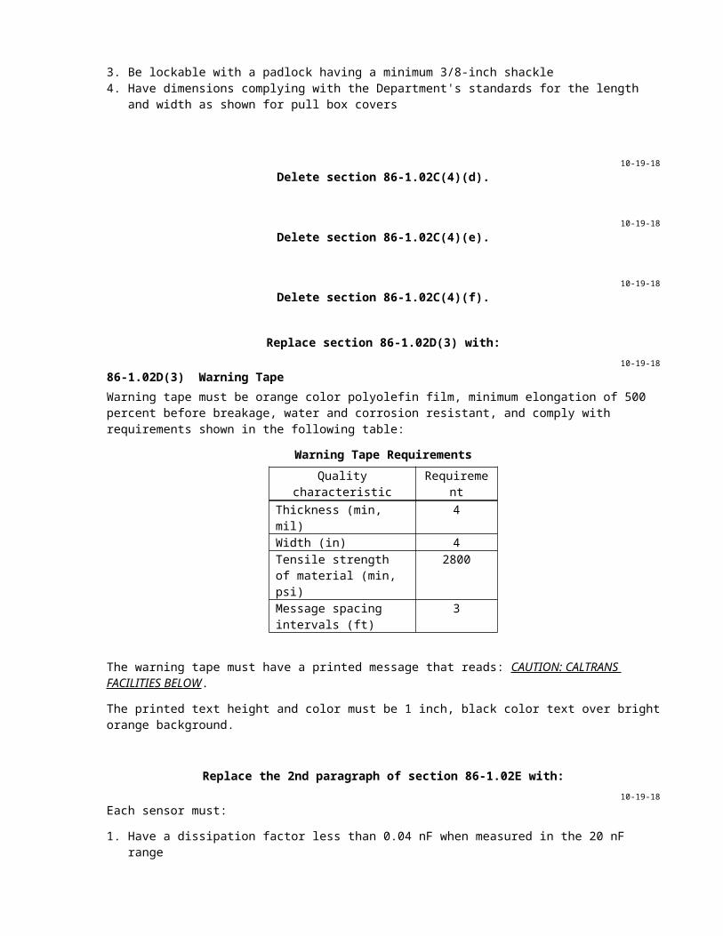
2.1. Volume is within ±3 percent accuracy2.2. Vehicle classification is within 95 percent accuracy by type
Replace the 7th paragraph of section 87-1.03A with:10-19-18
Notify the Engineer immediately if an existing facility is damaged by your activities:
1. Damaged existing traffic signal systems must be repaired or replaced within 24 hours. If the system cannot be fixed within 24 hours or it is located on a structure, provide a temporary system until the system can be fixed.
2. Damaged existing lighting systems must be repaired or replaced by nightfall. If the system cannot be fixed by nightfall, provide a temporary system until the system can be fixed.
Add to the end of section 87-1.03A:10-19-18
Collect the geographic information system mapping data.
Replace the 12th paragraph of section 87-1.03B(1) with:10-19-18
For Type 1, 2, and 5 conduits, use threaded bushings and bond them using a jumper. For other types of conduit, use nonmetallic bushings or end bell.
Replace the 3rd paragraph of section 87-1.03B(3)(a) with:10-19-18
Place a minimum of 2 inches of sand bedding in a trench before installing the conduit and 18 inches of slurry cement over the conduit before placing additional backfill material.
The slurry must be pigmented to match AMS-STD-595.
Replace the 1st sentence in the 6th paragraph of section 87-1.03B(3)(c) with:10-19-18
Backfill trench with slurry concrete under section 19-3.02E.
Replace the 9th paragraph of section 87-1.03B(3)(c) with:10-19-18
Install innerducts as one continuous unit between vaults. Innerducts may be interrupted inside pull boxes located between vaults and cabinets.
Replace section 87-1.03D with:10-19-18
87-1.03D Reserved
Replace section 87-1.03E(3) with:10-19-18
87-1.03E(3) Concrete Pads, Foundations, and PedestalsConstruct foundations for standards, poles, metal pedestals, and posts under section 56-3.
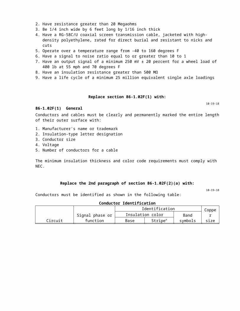
Construct concrete pads, foundations, and pedestals for controller cabinets, telephone demarcation cabinets, and service equipment enclosures on firm ground.
Install anchor bolts using a template to provide proper spacing and alignment. Moisten the forms and ground before placing the concrete. Keep the forms in place until the concrete sets for at least 24 hours to prevent damage to the surface.
Use minor concrete for pads, foundations, and pedestals.
Construct a pad in front of a Type III service equipment enclosure. The pad must be 24 inches in length, 4 inches in thickness, and must match the width of the foundation.
In unpaved areas, place the top of the foundation 6 inches above the surrounding grade, except place the top:
1. 1 foot 6 inches above the grade for 336L cabinets2. 1 foot 8 inches above the grade for Type C telephone demarcation cabinets3. 2 inches above the grade for Type III service equipment enclosures
The pad must be 2 inches above the surrounding grade in unpaved areas.
In and adjacent to the sidewalk and other paved areas, place the top of the foundation 4 inches above the surrounding grade, except place the top:
1. 1 foot 6 inches above the grade for 336L cabinets2. 1 foot 8 inches above the grade for Type C telephone demarcation cabinets3. Level with the finished grade for Type G and Type A cabinets and Type III service equipment
enclosures
The pad must be level with the finished grade in paved areas.
Apply an ordinary surface finish under section 51-1.03F.
Allow the foundation to cure for at least 7 days before installing any equipment.
Replace the 1st paragraph of section 87-1.03F(3)(c)(ii) with:10-19-18
Install a Type 1 or 2 inductive loop conductor except use Type 2 for Type E and F loop detectors.
10-19-18Delete the last paragraph of section 87-1.03G.
Replace the 4th paragraph of section 87-1.03H(2) with:10-19-18
Use Method B as follows:
1. Cover the splice area completely with an electrical insulating coating and allow it to dry.2. Apply 3 layers of half-lapped, PVC electrical tape.3. Apply 2 layers of butyl-rubber, stretchable tape with liner.4. Apply 3 layers of half-lapped, PVC, pressure-sensitive, adhesive tape.5. Cover the entire splice with an electrical insulating coating and allow it to dry.

Replace section 87-1.03N with:10-19-18
87-1.03N Fused Splice ConnectorsInstall a fuse splice connector with a fuse in each ungrounded conductor for luminaires, except for overhead sign luminaires. The connector must be located in the pull box adjacent to the luminaires.
If the pull box for the roadway luminaire is tamper resistant, install a fuse splice connector with 10 A fuse in the pull box and an additional fuse splice connector with a 5 A fuse in the handhole.
Install a fuse splice connector with a fuse on primary side of transformer.
Crimp the connector terminals onto the ungrounded conductors using a tool under the manufacturer's instructions. Insulate the terminals and make them watertight.
Add to the end of section 87-1.03T:10-19-18
When replacing an existing accessible pedestrian signal, the housing color must match the color of the existing housing.
Add to the end of section 87-1.03U:10-19-18
When replacing an existing push button assembly, the housing color must match the color of the existing housing.
Replace the 2nd paragraph of section 87-2.03A with:10-19-18
Tighten the cap screws of the luminaire's clamping bracket to 10 ft-lb for roadway luminaires.
Replace section 87-3 with:10-19-18
87-3 SIGN ILLUMINATION SYSTEMS87-3.01 GENERALSection 87-3 includes specifications for constructing sign illumination systems.
Sign illumination system includes:
1. Foundations2. Pull boxes3. Conduit4. Conductors5. Overhead sign luminaires6. Service equipment enclosure7. Photoelectric control
The components of a sign illumination system are shown on the project plans.
87-3.02 MATERIALSReserved
87-3.03 CONSTRUCTIONPerform the conductor test.
Install overhead sign luminaires under the manufacturer's instructions.

Do not modify the sign structure or mounting channels.
Perform the operational tests for the system.
87-3.04 PAYMENTNot Used
Replace section 87-4.01D with:10-19-18
87-4.01D Quality AssuranceReserved
Replace section 87-4.02B with:10-19-18
87-4.02B Battery Backup SystemA battery backup system includes the cabinet, batteries, and the Department-furnished electronics assembly.
The electronics assembly includes the inverter/charger unit, power transfer relay, manually-operated bypass switch, battery harness, utility interconnect wires, battery temperature probe, and relay contact wires.
Replace the 2nd sentence in the 15th paragraph of section 87-4.02C with:10-19-18
The background must comply with color no. 14109 of AMS-STD-595.
Replace section 87-4.03B with:10-19-18
87-4.03B Battery Backup System CabinetsInstall the battery backup system cabinet to the right of the controller cabinet.
If installation on the right side is not possible, obtain authorization for installation on the left side.
Provide access for power conductors between the cabinets using:
1. 2-inch nylon-insulated, steel chase nipple2. 2-inch steel sealing locknut3. 2-inch nylon-insulated, steel bushing
Remove the jumper between the terminals labeled BBS-1 and BBS-2 in the 5 position terminal block in the controller cabinet before connecting the Department-furnished electronics assembly.
Replace section 87-7.02 with:10-19-18
87-7.02 MATERIALSFlashing beacon control assembly includes:
1. Enclosure.2. Barrier-type terminal blocks rated for 25 A, 600 V(ac), made of molded phenolic or nylon material and
have plated-brass screw terminals and integral marking strips.3. Solid state flasher complying with section 8 of NEMA standards publication no. TS 1 for 10 A, dual
circuits.

4. 15-A, circuit breaker per ungrounded conductor.5. Single-hole-mounting toggle type, single-pole, single-throw switches rated at 12-A, 120 V(ac).
Switches must be furnished with an indicating nameplate reading Auto - Test. A 15-A circuit breaker may be used in place of the toggle switch.
Replace 87-8 with:10-19-18
87-8 PEDESTRIAN HYBRID BEACON SYSTEMS87-8.01 GENERAL87-8.01A SummarySection 87-8 includes specifications for constructing pedestrian hybrid beacon system.
A pedestrian hybrid beacon system includes:
1. Foundations2. Pull boxes3. Conduit4. Conductors and cables5. Standards6. Pedestrian hybrid beacon face7. Pedestrian signal heads8. Service equipment enclosure9. Department-furnished controller assembly10. Accessible pedestrian signals11. Push button assemblies12. Luminaires13. Fuse splice connectors14. Battery backup system
The components of a pedestrian hybrid beacon system are shown on the project plans.
87-8.01B DefinitionsReserved
87-8.01C SubmittalsReserved
87-8.01D Quality Assurance87-8.01D(1) GeneralReserved
87-8.01D(2) Quality ControlVerify the sequence for the pedestrian hybrid beacon system per California Chapter 4F, Figure 3F-3 "Sequence for a Pedestrian Hybrid Beacon" during the operational test.
Test the battery backup system under section 87-1.01D(2)(c).
87-8.02 MATERIALS87-8.02A GeneralThe system must comply with California MUTCD, Chapter 4F.
The battery backup system must comply with section 87-4.02B.
87-8.02B Pedestrian Hybrid Beacon FaceA pedestrian hybrid beacon face consists of three 12-inch signal heads.

87-8.03 CONSTRUCTIONInstall pedestrian hybrid beacon system under sections 87-4.03A and 87-4.03B.
87-8.04 PAYMENTNot Used
Replace the 1st paragraph of section 87-12.03 with:10-19-18
Install changeable message sign on sign structure under section 56-2.
Replace section 87-14.02 with:10-19-18
87-14.02 MATERIALS87-14.02A GeneralVehicle speed feedback sign consists of a housing, display window, and radar unit.
Sign must:
1. Comply with the California MUTCD, Chapter 2B2. Have an operating voltage of 120 V(ac) for permanent installations3. Have a maximum weight of 45 lb4. Have a wind load rating of 90 mph5. Have an operating temperature range from -34 to 165 degrees F6. Have a retroreflective white sheeting background
87-14.02B HousingsHousing must:
1. Be weatherproof (NEMA 3R or better) and vandal resistant2. Be made of 0.09-inch-gauge welded aluminum with the outer surfaces being UV resistant3. Have the manufacturer's name, model number, serial number, date of manufacture, rated voltage and
rated current marked inside4. Have the internal components easily accessible for field repair without removal of the sign
87-14.02C Display WindowsDisplay window consists of a cover, LED character display, and dimming control. Character display and cover must deflect together without damage to the internal electronics and speed detection components.
Cover must be:
1. Vandal resistant and shock absorbent2. Field replaceable with the removal of external stainless-steel, tamper proof fasteners
Cover must be made of a minimum 0.25-inch-thick, shatter-resistant polycarbonate.
LED character display must:
1. Consist of two 7-segment, solid-state, numeric characters, which must:1.1. Be a minimum 15 inches in height1.2. Be visible and legible from a minimum distance of 1500 feet and legible from a minimum
distance of 750 feet1.3. Consist of a minimum 16 LEDs, which must:
1.3.1. Be amber and have a wavelength from 590 to 600 nm and rated for minimum 100,000 hours
1.3.2. Must maintain a minimum 85 percent of the initial light output after 48 months of continuous use over the temperature range
2. Be capable of displaying the detected vehicle speed within 1 second

3. Remain blank when no vehicles are detected within the radar detection zone4. Have the option to flash the pre-set speed limit when the detected vehicle speed is 5 miles higher
than the pre-set speed5. Be viewable only by the approaching traffic
Dimming control must:
1. Automatically adjust the character light intensity to provide optimum character visibility and legibility under all ambient lighting conditions
2. Have minimum 3 manual dimming modes of different intensities
87-14.02D Radar UnitsRadar unit must:
1. Be able to detect up to 3 lanes of approaching traffic2. Operate with an internal, low power, 24.159 GHz (K-band)3. Be FCC approved Part 15 certified4. Have a speed accuracy of ±1 mph5 Have a maximum 15 W power consumption
Replace 87-19 with:10-19-18
87-19 FIBER OPTIC CABLE SYSTEMS87-19.01 GENERAL87-19.01A SummarySection 87-19 includes specifications for constructing fiber optic cable systems.
A fiber optic cable system includes:
1. Conduit and accessories2. Vaults3. Warning tape4. Fiber optic cables5. Fiber optic splice enclosures6. Fiber distribution units7. Fiber optic markers8. Fiber optic connectors and couplers
The components of a fiber optic system are shown on the project plans.
87-19.01B DefinitionsReserved
87-19.01C SubmittalsAt least 15 days before cable installation, submit:
1. Manufacturer’s procedures for pulling fiber optic cable2. Test reports from a laboratory accredited to International Standards Organization/International
Electrotechnical Commission 17025 by the American Association for Laboratory Accreditation (A2LA) or the ANSI-ASQ National Accreditation Board (ANAB) for:2.1. Water penetration2.2. Cable temperature cycling2.3. Cable impact2.4. Cable tensile loading and fiber strain2.5. Cable compressive loading2.6. Compound flow2.7. Cyclic flexing
3. Proof of calibration for the test equipment including:
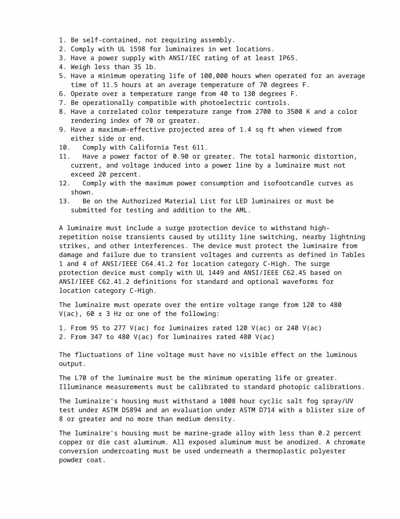
3.1. Name of calibration facility3.2. Date of calibration3.3. Type of equipment, model number and serial number3.4. Calibration result
Submit optical time-domain reflectometer data files for each test in a Microsoft Excel format.
After performing the optical time-domain reflectometer test and the power meter and light source test, submit within 4 business days a hard copy and electronic format:
1. Cable Verification Worksheet2. Segment Verification Worksheet3. Link Loss Budget Worksheet
The worksheets are available at the Division of Construction website.
87-19.01D Quality Assurance87-19.01D(1) GeneralReserved
87-19.01D(2) Quality ControlNotify the Engineer 4 business days before performing field tests. Include exact location of the system or components to be tested. Do not proceed with the testing until authorized. Perform each test in the presence of the Engineer.
The optical time-domain reflectometer test consists of:
1. Inspecting the cable segment for physical damage.2. Measuring the attenuation levels for wavelengths of 1310 and 1550 nm in both directions for each
fiber using the optical time-domain reflectometer.3. Comparing the test results with the data sheet provided with the shipment. If there are attenuation
deviations greater than 5 percent, the test will be considered unsatisfactory and the cable segment will be rejected. The failure of any single fiber is a cause for rejection of the entire segment. Replace any rejected cable segments and repeat the test.
The power meter and light source test consists of:
1. Testing each fiber in a link using a light source at one end of the link and a power meter at the other end
2. Measuring and recording the power loss for wavelengths of 1310 and 1550 nm in both directions
Index matching gel is not allowed.
Installation and splicing of the fiber optic cable system must be performed by a certified fiber optic installer.
The optical time-domain reflectometer test and the power meter and light source test must be performed by a certified fiber optic technician.
The certification for the fiber optic installer and fiber optic technician must be from an organization recognized by the International Certification Accreditations Council and must be current throughout the duration of the project.
87-19.02 MATERIALS87-19.02A GeneralAll metal components of the fiber optic cable system must be corrosion resistant.
All connectors must be factory-installed and tested.
Patch cords, pigtails, and connectors must comply with ANSI/TIA-568.
Pigtails must have a minimum 80 N pull out strength.
A splice cassette may be used in place of a pigtail and a splice tray.
Each cable reel must have a weatherproof label or tag with information specified in ANSI/ICEA S-87-640 including:
1. Contractor's name2. Contract number3. Number of fibers4. Cable attenuation loss per fiber at 1310 and 1550 nm
The labeled or tagged information must also be in a shipping record in a weatherproof envelope. The envelope must be removed only by the Engineer.
87-19.02B VaultsA vault must:
1. Comply with section 86-1.02C and AASHTO HS 20-44, and load tested under AASHTO M 306.2. Be a minimum:
2.1. 4 feet wide by 4 feet high by 4 feet long nominal inside dimensions for box type.2.2. 4 feet high by 4 feet outside diameter for round type.
3. Have a minimum access of:3.1. 30 inches diameter for round type.3.2. 3 feet wide by 3 feet long for box type.
4. Be precast either modular or monolithic.5. Have cable racks installed on the interior sides. A rack must:
5.1. Be fabricated from ASTM A36 steel plate.5.2. Support a minimum of 100 pounds per rack arm.5.3. Support a minimum of 4 splice enclosures and a minimum of 4 cables with a minimum slack of
50 feet each.5.4. Be hot-dip galvanized after manufacturing.5.5. Be bonded and grounded.
6. Have a minimum:6.1. Two 4-inch diameter knockouts on each side for box type.6.2. Two 4-inch diameter knockouts placed every 90 degrees for round type.
7. Have a minimum 2-inch-diameter drain hole at the center of base.
Entry points for knockouts must not cause the cable to exceed its maximum bend radius.
The access cover must:
1. Be a two-piece torsion-assisted sections or a minimum 30-inch-diameter cast iron.2. Have inset lifting pull slots.3. Have markings CALTRANS and FIBER OPTIC.
87-19.02C Fiber Optic CableThe fiber optic cable must:
1. Comply with 7 CFR parts 1755.900, 1755.901, and 1755.902, and ANSI/ICEA S-87-6402. Be a singlemode, zero-dispersion, and have non-gel loose type buffer tubes3. Have no splices4. Have a Type H or Type M outer jacket5. Be shipped on a reel6. Have 10 feet of length on each end of the cable accessible for testing
87-19.02D Fiber Optic Splice EnclosuresA fiber optic splice enclosure must:
1. Not exceed 36 inches in length, 8 inches in width, and 8 inches in height2. Be made of thermoplastic material, weather proof, chemical and UV resistant, and re-sealable3. Accommodate a minimum of 8 internal splice trays4. Have from 1/4 to 1 inch in diameter cable entry ports
5. Have brackets, clips and cable ties6. Have means to anchor the dielectric member of the fiber optic cable7. Include grounding hardware
87-19.02E Fiber Distribution UnitsThe fiber distribution unit consists of a housing, a patch panel, a 12-multicolor pigtail, and a splice tray.
The fiber distribution unit must be self-contained and pre-assembled.
The housing must:
1. Be a 19-inch rack-mountable modular-metal enclosure2. Be a one rack unit3. Have cable clamps to secure buffer tube to the chassis4. Have cable accesses with rubber grommets or similar material to prevent the cable from coming in
contact with the bare metal5. Be weatherproof6. Have a hinged top door with a latch or thumbscrew to hold it in the closed position
A patch panel must have a minimum of 12-singlefiber type connector sleeves.
A pigtail must:
1. Be a simplex single mode fiber in a 900 µm tight buffer with a 12-inch-outer-diameter PVC jacket2. Have a fiber optic connector attached on one end and bare fiber on the other end3. Be at least 3 feet in length4. Have the manufacturer's part number on the jacket
Pigtails must be single-fiber or ribbon type.
87-19.02F Patch CordsPatch cords must:
1. Be a singlemode fiber in a 900 µm tight buffer with a 0.12-inch-outer-diameter PVC jacket2. Have fiber optic connectors attached on both ends3. Be at least 6 feet in length4. Have manufacturer's part number on the jacket
Duplex patch cords must be of round cable structure, and not have zip-cord structure.
87-19.02G Splice TraysSplice trays must:
1. Have brackets to spool incoming fibers a minimum of 2 turns.2. Have means to secure and protect incoming buffer tubes, pigtails, and a minimum of 12 heat shrink
fusion splices.3. Be stackable.4. Have a snap-on or hinged cover. The cover may be transparent.
87-19.02H Fiber Optic MarkersFiber optic markers must be:
1. Type K-2 (CA) object markers for vaults or pull boxes.2. Disk markers for paved areas and transition points from unpaved to paved areas. The disk marker
must be metallic, lead free and 4 inches in diameter, and must have a mounting stem at the center of the disk. The mounting stem must be a minimum 3 inches long and a minimum 0.70 inch in diameter.
3. Non-reflective Class 1, Type F, flexible post delineators for unpaved areas.
87-19.02I Fiber Optic Connectors and CouplersConnectors must be:
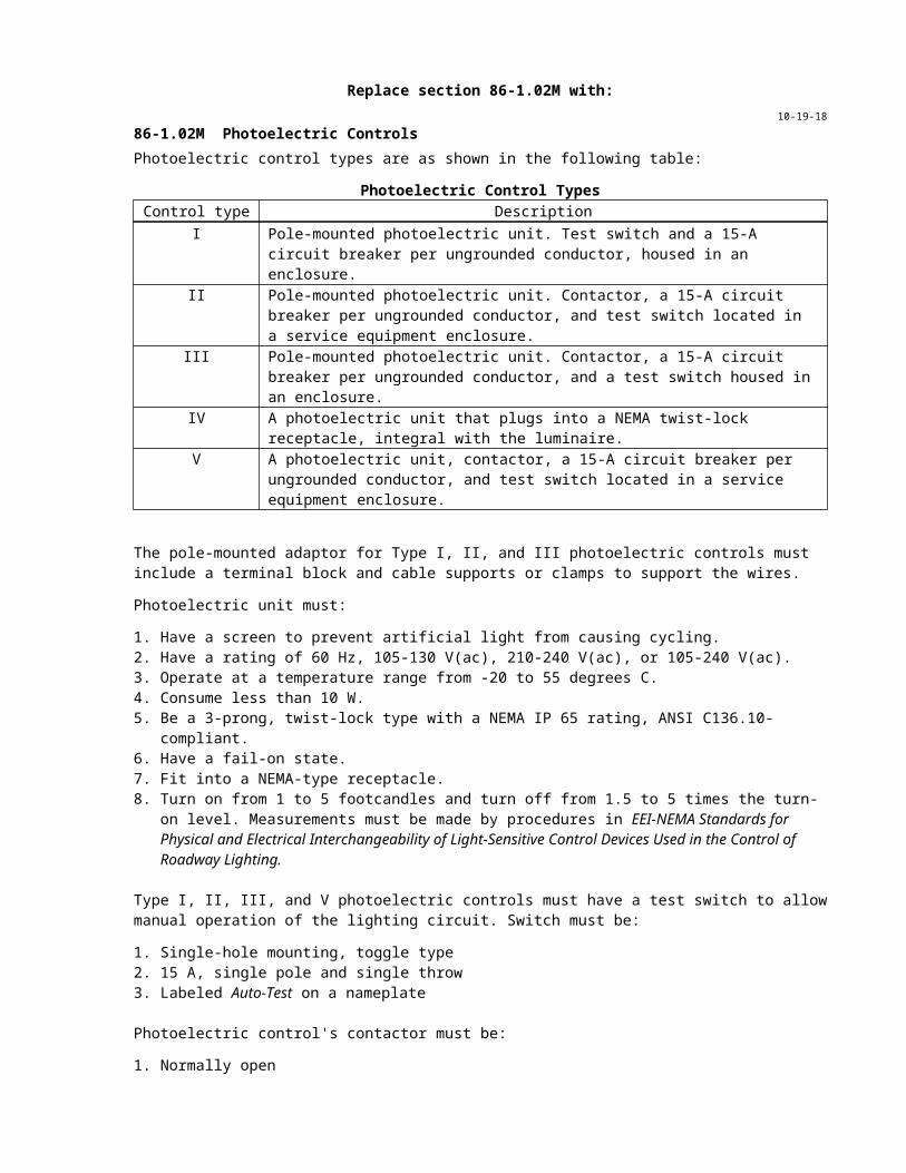
1. 0.1-inch ceramic ferrule pre-radiused type2. Capped when not used
Couplers must be made of the same material as the connector's housing and have ceramic sleeves.
Singlemode fiber optic connectors must have a yellow strain relief boot or a yellow base.
87-19.03 CONSTRUCTION87-19.03A GeneralPerform the optical time-domain reflectometer test:
1. On the fiber optic cable upon its arrival to the job site and before its installation. Complete the Cable Verification Worksheet. Do not install the fiber optic cable until the Engineer's written approval is received.
2. After the fiber optic cable segments have been pulled, but before breakout and termination. Complete the Segment Verification Worksheet.
3. Once the passive cabling system has been installed and is ready for activation. If the measured individual fusion splice losses exceed -0.30 dB, re-splice and retest. At the conclusion of the optical time-domain reflectometer test, perform the power meter and light source test. If the measured link loss exceeds the calculated link loss, replace the unsatisfactory cable segments or splices and retest. Complete the Link Loss Budget Worksheet.
87-19.03B Vaults InstallationInstall a vault as shown and with the side facing the roadway a minimum of 2 feet from the edge of pavement or back of dike, away from traffic.
Install the top of the vault flush with surrounding grade in paved areas and 2 inches above the surrounding grade in unpaved areas.
Place 6 inches of minor concrete around vaults. In unpaved areas, finish top of concrete at a 2 percent slope away from cover. In paved areas, finish top of concrete to match existing slope.
Bolt the steel cover to the vault when not working in it.
87-19.03C Fiber Optic Cable InstallationInstall fiber optic cable by a certified installer or a representative from the fiber optic cable manufacturer during installation.
When using mechanical aids to install fiber optic cable:
1. Maintain a cable bend radius at least twenty times the outside diameter of the cable2. Use cable grips having a ball bearing swivel3. Use a pulling force on a cable not to exceed 500 pound-foot or manufacturer's recommended pulling
tension, whichever is less
When installing the cable using the air blown method, the cable must withstand a static air pressure of 110 psi.
Lubricate the cable using a lubricant recommended by the cable manufacturer.
Install fiber optic cable without splices except where shown.
Provide a minimum of 65 feet of slack for each fiber optic cable at each vault. Divide the slack equally on each side of the splice enclosure.
Install tracer wires in the fiber optic conduits and innerducts as shown. Provide a minimum 5 feet of slack tracer wire in each pull box and vault from each direction. You may splice tracer wire at intervals of not less than 500 feet and only inside vaults or pull boxes.
If a fiber optic cable and tracer wire is installed in an innerduct, pulling a separate fiber optic cable into a spare duct to replace damaged fiber will not be allowed.
Apply a non-hygroscopic filling compound to fiber optic cable openings.

Seal the ends of conduit and innerducts after cables are installed.
Install strain relief for fiber optic cable entering a fiber optic enclosure.
Identify fibers and cables by direct labeling, metal tags, or bands fastened in such a way that they will not move. Use mechanical methods for labeling.
Provide identification on each fiber optic cable or each group of fiber optic cables in each vault and at the end of terminated fibers. Fiber optic cable must be identified as shown in the following table:
Cable Identificationa
Sequence order
Description Code Numbers of characters
1 Fiber type S: Singlemode 12 Fiber count ###: Example 048 33 Begin point T: TMC
H: HubV: Video NodeD: Data NodeC: Cable NodeTV: CameraCM: CMSE: Traffic SignalRM: Ramp MeterTM: Traffic Monitoring/ Count Station/Vehicle Count Station (VDS, TMS)HA: Highway Advisory RadioEM: Extinguishable Message SignRW: Roadway Weather Information SystemWM: Weigh In MotionWS: Weigh-Station Bypass SystemSV: VaultSC: Splice Cabinet
1 or 2
4 Begin point county abbreviation
AA or AAA: Examples: Orange (ORA), San Mateo (SM) 2 or 3
5 Begin point route number
###: Examples: 005, 082, 114 3
6 Begin point post mile
#####: 02470 (example 024.70): Actual PM value to the 1/100 value 5
7 End Point In the same way as for Begin Point 1 or 2
8 End point county abbreviation
In the same way as for Begin Point County Abbreviation 2 or 3
9 End point route number
In the same way as Begin Point Route Number 3
10 End point post mile
In the same way as Begin Point Post Mile 5
aCable identification example: The cable code S 048 SV SM 084 02470 SV SC 082 02510 describes a singlemode, 48 strand, cable starting at a fiber optic vault in San Mateo County on Route 84 at post mile 24.70, and ending at another fiber optic vault in Santa Clara County on Route 82 at post mile 25.10.
Place labels on the cables at the following points:
1. Fiber optic vault and pull box entrances and exits2. Splice enclosures entrance and exit

3. Fiber distribution unit entrance
Lace fiber optic cable inside controller cabinets and secure to the cage.
Support the fiber optic cable within 6 inches from a termination and every 2 feet.
Secure fiber optic cables to the cable racks. Store excess cable in a figure 8 fashion.
87-19.03D Fiber Optic Cable SplicesUse fusion splicing for fiber optic cables.
Splice single-buffer tube cable to multi-buffer tube cable using the mid-span access method under manufacturer's instructions. Any mid-span access splice or fiber distribution unit termination must involve only those fibers being spliced as shown.
Place fiber splices in the splice enclosures installed in the vaults.
87-19.03E Splice Enclosures InstallationMaintain an equal amount of slack on each side of the splice enclosure.
Secure the fiber optic splices in splice tray.
Secure the splice trays to the inner enclosure.
Label cables and buffer tubes.
Do not seal fiber splice enclosure until authorized and the power meter and light source test is performed. Seal the enclosure under manufacturer's instructions.
Flash test the outer enclosure under manufacturer's instructions in the presence of the Engineer. Visually inspect the enclosure. If bubbles are present, identify the locations where the bubbles are present, take corrective actions and repeat the flash test until no bubbles are present.
Attach the splice enclosure to the side wall of a vault or hub with a minimum 2 feet distance between the ground and the bottom of the enclosure.
Secure fiber optic cables to the chassis using cable clamps for fiber optic units.
Connect a minimum of one bonding conductor to a grounding electrode after mounting the fiber optic enclosure to the wall. If there are multiple bonding conductors, organize the conductors in a neat way.
87-19.03F Fiber Optic Distribution Unit InstallationSpool incoming buffer tubes 2 feet in the splice tray and expose 1 foot of individual fibers.
Maintain a minimum 2-inch-bend radius during and after installation in the splice tray.
Splice incoming fibers in the splice tray.
Restrain each fiber in the splice tray. Do not apply stress on the fiber when located in its final position.
Secure buffer tubes near the entrance of the splice tray.
Secure splice trays under manufacturer's instructions.
Label splice tray after splicing is completed.
Install patch cords in fiber distribution units and patch panels. Permanently label each cord and each connector in the panel with the system as shown.
87-19.03G Fiber Optic Markers InstallationInstall fiber optic markers at 12-inch offset on the side furthest away from the edge of travel way:
1. For fiber optic cable at 500 feet apart in areas where the distance between vaults or pull boxes is greater than 500 feet
2. Adjacent to vaults and pull boxes

3. For fiber optic cable turns at:3.1. Beginning of the turn3.2. Middle of the arc3.3. End of the turn
When a fiber optic cable crosses a roadway or ramp, install a disk marker over the conduit trench on:
1. Every shoulder within 6 inches from the edge of pavement2. Delineated median3. Each side of a barrier
Install markers under section 81 except each retroreflective face must be parallel to the road centerline and facing away from traffic.
87-19.04 PAYMENTNot Used
Replace 87-20 with:10-19-18
87-20 TEMPORARY ELECTRICAL SYSTEMS87-20.01 GENERALSection 87-20 includes specifications for providing temporary electrical systems.
Obtain the Department's authorization for the type of temporary electrical system and its installation method.
A temporary system must operate on a continuous, 24-hour basis.
A temporary electrical system must have a primary power source and a back-up power source from the following power sources:
1. Commercial power from a utility company2. Generator system3. Photovoltaic system
87-20.02 MATERIALS87-20.02A GeneralMaterial and equipment may be new or used.
Temporary wood poles must comply with section 48-6.
The components of a temporary system are shown on the project plans.
If you use Type UF-B cable, the minimum conductor size must be no. 12.
87-20.02B Temporary Flashing Beacon SystemsA temporary flashing beacon system consists of a flashing beacon system, wood post, and a power source.
The system must comply with the specifications for a flashing beacon system in section 87-7, except it may be mounted on a wood post or a trailer.
87-20.02C Temporary Lighting SystemsA temporary lighting system consists of a lighting system, a power source, and wood poles.
The system must comply with the specifications for a lighting system in section 87-2, except it may be mounted on a wood pole or a trailer.

87-20.02D Temporary Signal SystemsA temporary signal system consists of a signal and lighting system, wood poles and posts, and a power source.
System must comply with the specifications for a signal and lighting system in section 87-4, except:
1. Signal heads may be mounted on a wood pole, mast arm, tether wire, or a trailer2. Flashing beacons may be mounted on a wood post, or a trailer
87-20.02E GeneratorsA generator must:
1. Be 120 V(ac) or 120/240 V(ac), 60 Hz, 2.5 kW minimum, continuous-duty type2. Be powered by a gasoline, LPG, or diesel engine operating at approximately 1,800 rpm with an
automatic oil feed3. Be equipped to provide automatic start-stop operation with a 12 V starting system4. Have generator output circuits that have overcurrent protection with a maximum setting of 15 A5. Have enough fuel storage to operate when it is unattended6. Have a spark arrester complying with Pub Cont Code § 4442
A back-up power source must:
1. Have an automatic transfer switch2. Start automatically and transfer the system load upon reaching the operating voltage, in the event of
a power source failure
87-20.02F Automatic Transfer SwitchesAn automatic transfer switch must provide:
1. Line voltage monitoring in the event of a power outage that signals the back-up power source to start2. Start delay, adjustable from 0 to 6 seconds, to prevent starting if the power outage is only momentary
and a stop delay, adjustable from 0 to 8 minutes, to allow the back-up power source to unload.3. Transfer delay from 0 to 120 seconds to allow the back-up power source to stabilize before
connecting to the load and retransfer delay from 0 to 32 minutes to allow the line voltage to stabilize.4. Mechanical interlock to prevent an application of power to the load from both sources and to prevent
backfeeding from the back-up power source to the primary power source.
87-20.03 CONSTRUCTION87-20.03A GeneralProvide electrical and telecommunication services for temporary systems. Do not use existing services unless authorized.
Provide power for the temporary electrical systems.
Commercial power must be 120 V(ac) or 120/240 V(ac) single phase. Make arrangements with the utility company for providing service. Protect the power source in a locked enclosure. Provide keys to all locks to the Engineer.
Install conductors and cables in a conduit, suspended from wood poles at least 25 feet above the roadway, or use direct burial conductors and cables.
You may saw slots across paved areas for burial conductors and cables.
Install conduit outside the paved area at a minimum of 12 inches below grade for Type 1 and 2 conduit and at a minimum of 18 inches below grade for Type 3 conduit.
Install direct burial conductors and cables outside the paved area at a minimum depth of 24 inches below grade.
Place the portions of the conductors installed on the face of wood poles in either Type 1, 2, or 3 conduit between the point 10 feet above grade at the pole and the pull box. The conduit between the pole and the pull box must be buried at a depth of at least 18 inches below grade.
Place conductors across structures in a Type 1, 2, or 3 conduit. Attach the conduit to the outside face of the railing.
Mount the photoelectric unit at the top of the standard or wood post.
You may abandon in place conductors and cables in sawed slots or in conduit installed below the ground surface.
87-20.03B Temporary Flashing Beacon SystemsProtect each flashing beacon with a fused splice connector on the line side. Wherever conductors are run overhead, install the splice connector in the line side outside of the control assembly.
87-20.03C Temporary Lighting SystemsProtect each luminaire with a fused splice connector on the line side. Wherever conductors are run overhead, install the fuse splice connectors in the line side before entering the mast arm.
87-20.03D Temporary Signal SystemsYou may splice conductors that run to a terminal compartment or a signal head on a pole to the through conductors of the same phase in a pull box adjacent to the pole. Do not splice conductors or cables except in a pull box or in a NEMA 3R enclosure.
The Department provides the timing for the temporary signal.
Maintain the temporary signal except for the Department-furnished controller assembly.
87-20.04 PAYMENTNot Used
Replace item 7 in the list in the 2nd paragraph of section 87-21.03B(2) with:10-19-18
7. Camera system
^^^^^^^^^^^^^^^^^^^^^^^^^^^^^^^^^^^^^^^^^^^^^^^^^^^^^^^^^^^^
DIVISION XI MATERIALS90 CONCRETE
10-19-1810-19-18
Delete the 2nd paragraph of section 90-3.02A.
^^^^^^^^^^^^^^^^^^^^^^^^^^^^^^^^^^^^^^^^

96 GEOSYNTHETICS10-19-18
Replace the 3rd table in the 3rd paragraph of section 96-1.02R with:10-19-18
Cushion Fabric
Quality characteristic Test method RequirementClass 10 Class 12 Class 16 Class 24 Class 32 Class 60
Mass per unit area (oz/sq yd) ASTM D5261 10 12 16 24 32 60Grab tensile break strength (min, lb) ASTM D4632 230 300 370 450 500 630Grab tensile break elongation (min, %) ASTM D4632 50Puncture strength (min, lb) ASTM D6241 700 800 900 1100 1700 2400Trapezoidal tear strength (min, lb) ASTM D4533 95 115 145 200 215 290UV resistance (min, %) ASTM D7238 70