1999 thurston county road standards
TRANSCRIPT

ROAD STANDARDS
THURSTON COUNTYWASHINGTONSINCE 1852
JANUARY 1999
i
1.00 INTRODUCTION
1.01 Current Edition of the Standards1.02 Application of Standards
2.00 GENERAL CONSIDERATIONS
2.01 Applicability2.02 Definitions2.03 Adopted Thurston County Specifications2.04 Exemptions2.05 Interpretation and Enforcement2.06 Project Acceptance2.07 Time Limitation of Acceptance2.08 Variances from the Standards2.09 Environmental Considerations2.10 Violations and Penalties2.11 Severability2.12 Fees2.13 Transportation Improvements2.14 Grading Permits2.15 Grading Plan2.16 Securities2.17 Withdraw of Approval/Acceptance2.18 Site Maintenance2.19 Correspondence
3.00 PLAN FORMAT
3.01 Submittal Procedure3.02 General Formatting3.03 Plan Elements3.04 Profile Elements3.05 Typical Cross Section3.06 Intersection Plan Details3.07 Drainage and Erosion Control Plan3.08 As-built Drawings3.09 Standard Notes3.10 Construction Staking
Appendix 3 - A Standard Notes
ii
4.00 ROAD TYPES AND GEOMETRICS
4.01 Functional Classifications in Rural Areas4.02 Functional Classifications in Urban Areas4.03 Maximum and Minimum Grades4.04 Sight Distances4.05 Private Roads4.06 Half Roads4.07 New Driveways4.08 Emergency Turnarounds4.09 Intersections4.10 Medians and Planters4.11 One-way Roads4.12 Dedications4.13 Railroad Grade Crossings4.14 Traffic Control4.15 Exception to Paving on Rural Local Roads4.16 Slope, Wall, and Drainage Easements4.17 Road Network Circulation4.18 On-Site Principles4.19 Dead End Roads4.20 Roadside Obstacles
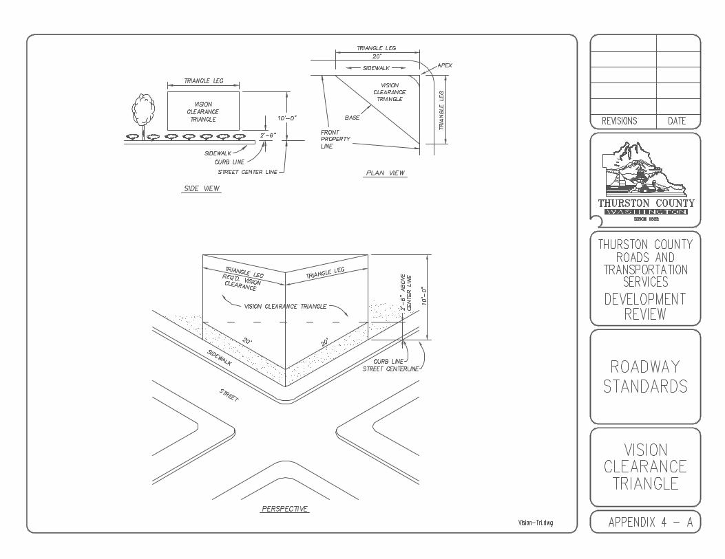
Appendix 4 - A Vision Clearance Triangle
5.00 TRAFFIC ANALYSIS GUIDELINES
5.01 Purpose5.02 Level of Analysis5.03 Warrants for a Level I TIA5.04 Warrants for a Level II TIA5.05 Traffic Generation Guidelines5.06 Peak Traffic Hours5.07 Level of Service5.08 Concurrency5.09 Report Certification5.10 Scoping5.11 Background Study Area Data5.12 Safety Analysis
Appendix 5 - A Level I AnalysisAppendix 5 - B Level I Grand Mound AnalysisAppendix 5 - C Level II Analysis
iii
6.00 ROADWAY BASES, SURFACING AND RESTORATION
6.01 Surfacing Requirements6.02 Restoration
Appendix 6 - A Private Roadway SectionAppendix 6 - B Minor Local Roadway SectionAppendix 6 - C Local Roadway SectionAppendix 6 - D Collector Roadway SectionAppendix 6 - E Arterial Roadway SectionAppendix 6 - F Clear Zone/Recovery AreaAppendix 6 - G Cul-de-Sac, Hammerhead DetailAppendix 6 - H Utility Trench Detail
7.00 ACCESS
7.01 General7.02 Sight Distance7.03 Location of Access Points7.04 Construction of Access Points7.05 Horizontal Alignment of Access Points7.06 Vertical Alignment of Access Points7.07 Left Turn, Acceleration and Deceleration Lanes7.08 Intersections
Appendix 7 - A County Road AccessesAppendix 7 - B Access Point Grades
8.00 ROADSIDE FEATURES
8.01 Side Slopes8.02 Survey Monuments8.03 Mailboxes8.04 Landscaping8.05 Road Illumination8.06 Roadway Barricades8.07 Bollards8.08 Guardrail8.09 Off-Road Parking Spaces8.10 Road Name Signs8.11 Stop Signs8.12 Roadway Striping, Buttoning, and Delineation
Appendix 8 - A Survey Monument StandardAppendix 8 - B Community Mail Box

iv
9.00 RETAINING WALLS
9.01 Design Criteria9.02 Rock Retaining Walls
Appendix 9 - A Rock Retaining Wall
10.00 BRIDGES
10.01 Principle References10.02 Bridge Geometrics10.03 Bridge Design Criteria10.04 Special Permits10.05 Existing Bridges
11.00 DRAINAGE
11.01 Catch Basins, Manholes and Inlets
12.00 UTILITIES
13.00 CONSTRUCTION CONTROL AND INSPECTION
13.01 Basis for Control of Work13.02 Engineer Certification13.03 Inspection Criteria13.04 Notification Requirements13.05 Revisions to Inspection Sequence13.06 Required Inspections to be Performed by the Applicant13.07 Materials Sampling and Testing
14.00 FRONTAGE IMPROVEMENTS
14.01 Exceptions14.02 Alternatives
15.00 UNOPENED County RIGHT-OF-WAY
Appendix 15 - A Unopened County Right-of-Way Standard
v
16.00 URBAN FEATURES
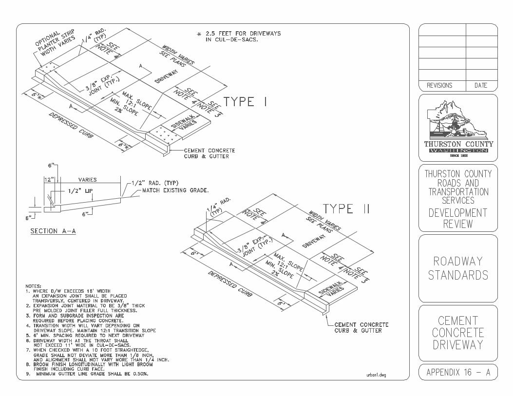
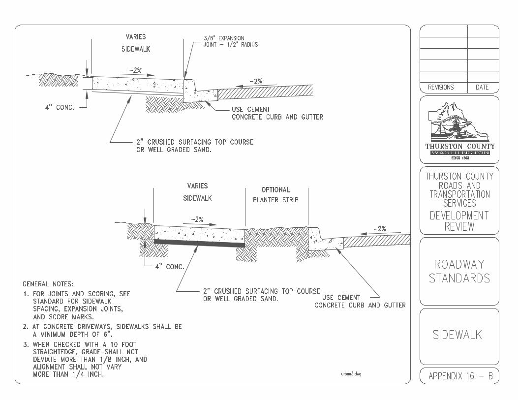
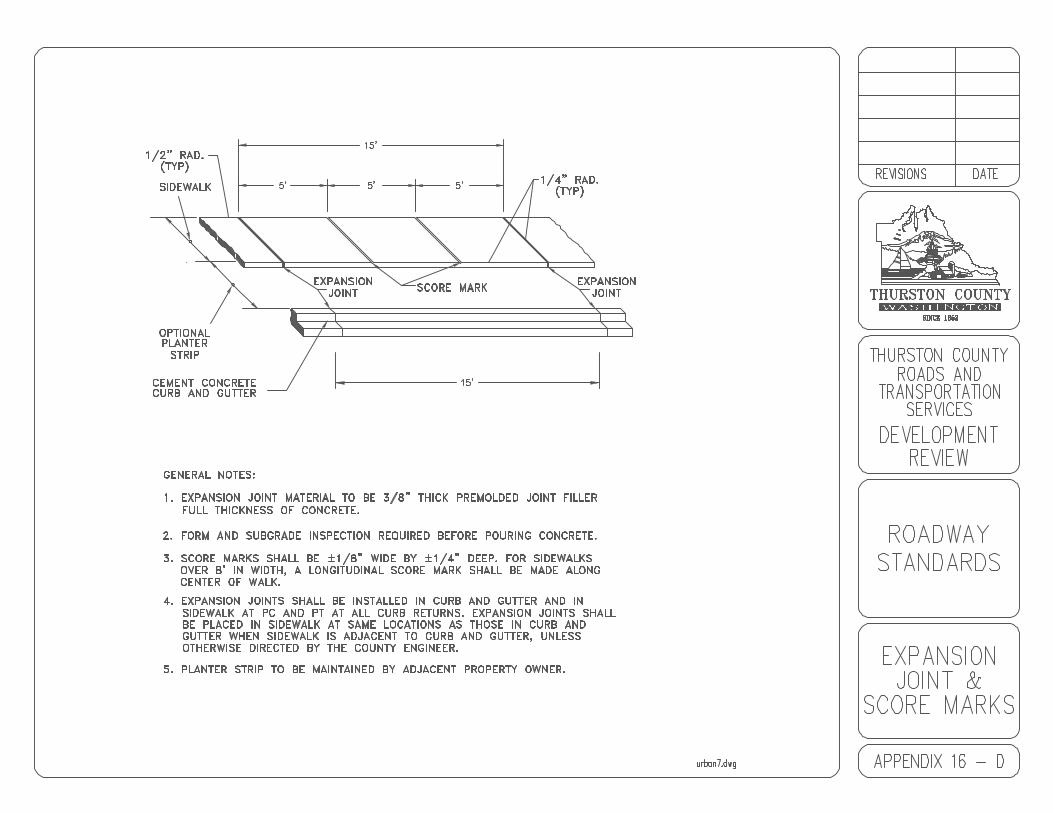
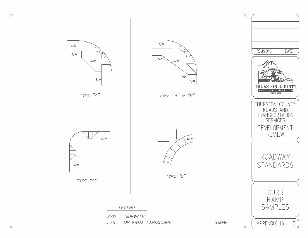
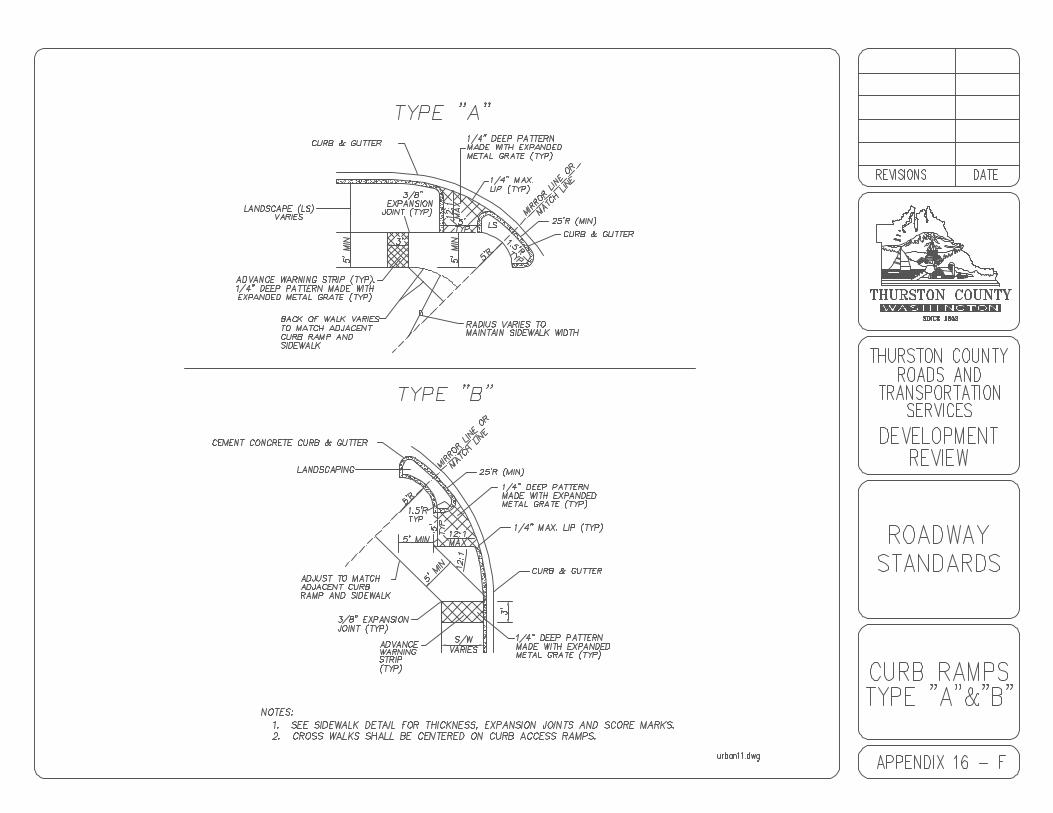
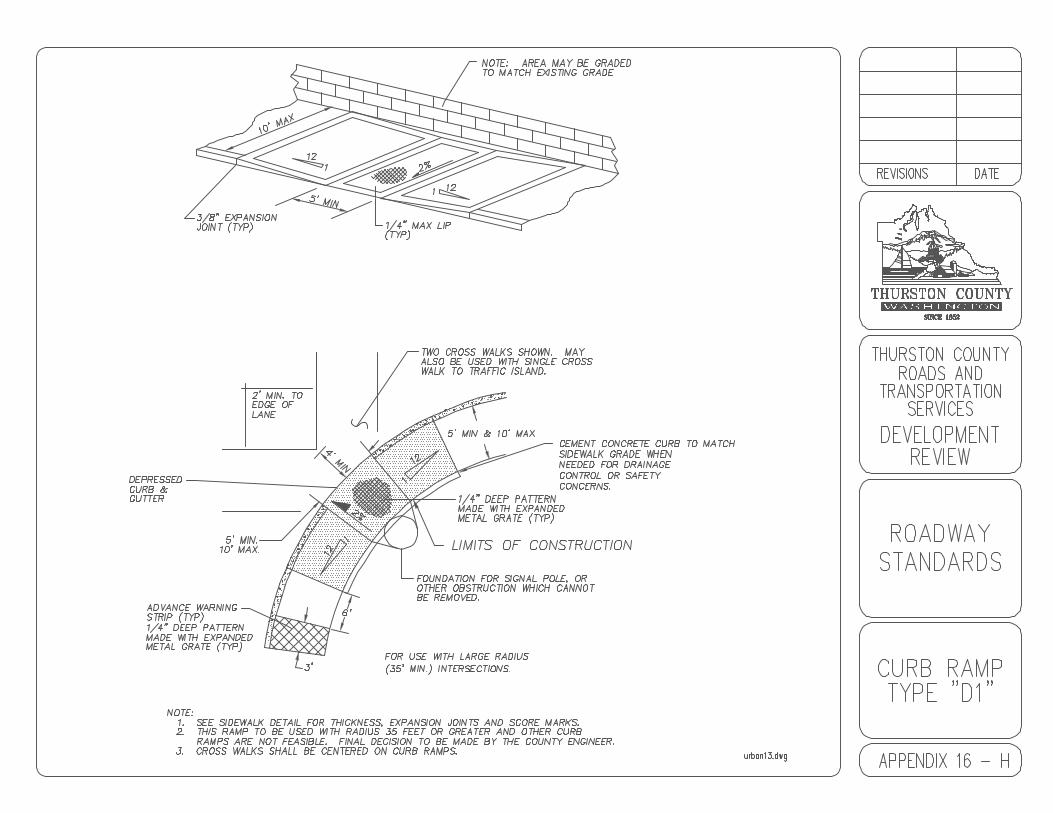
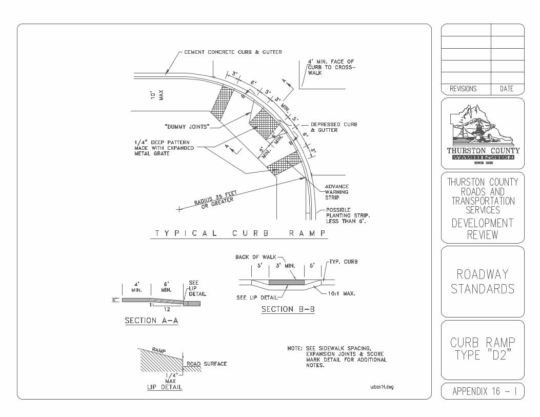
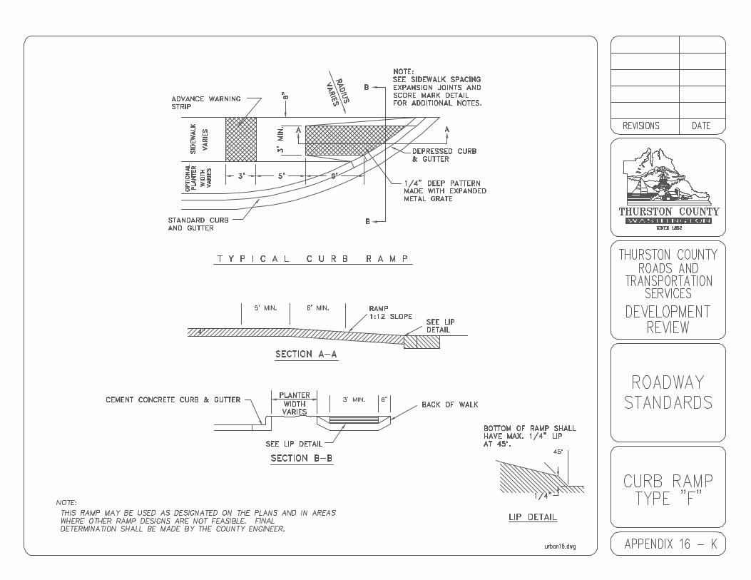
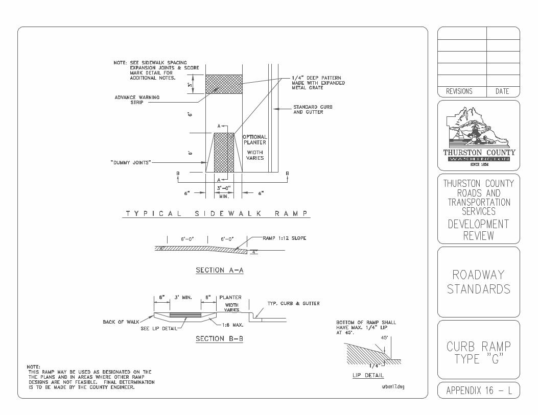
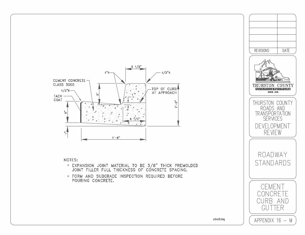
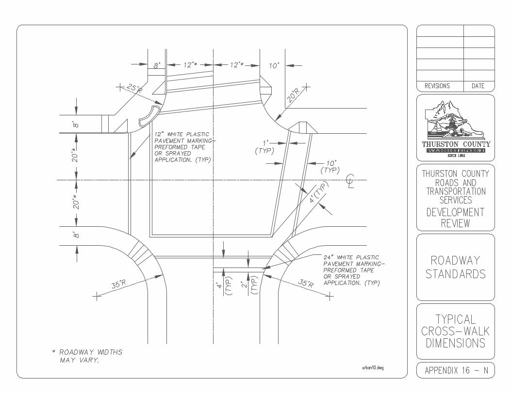
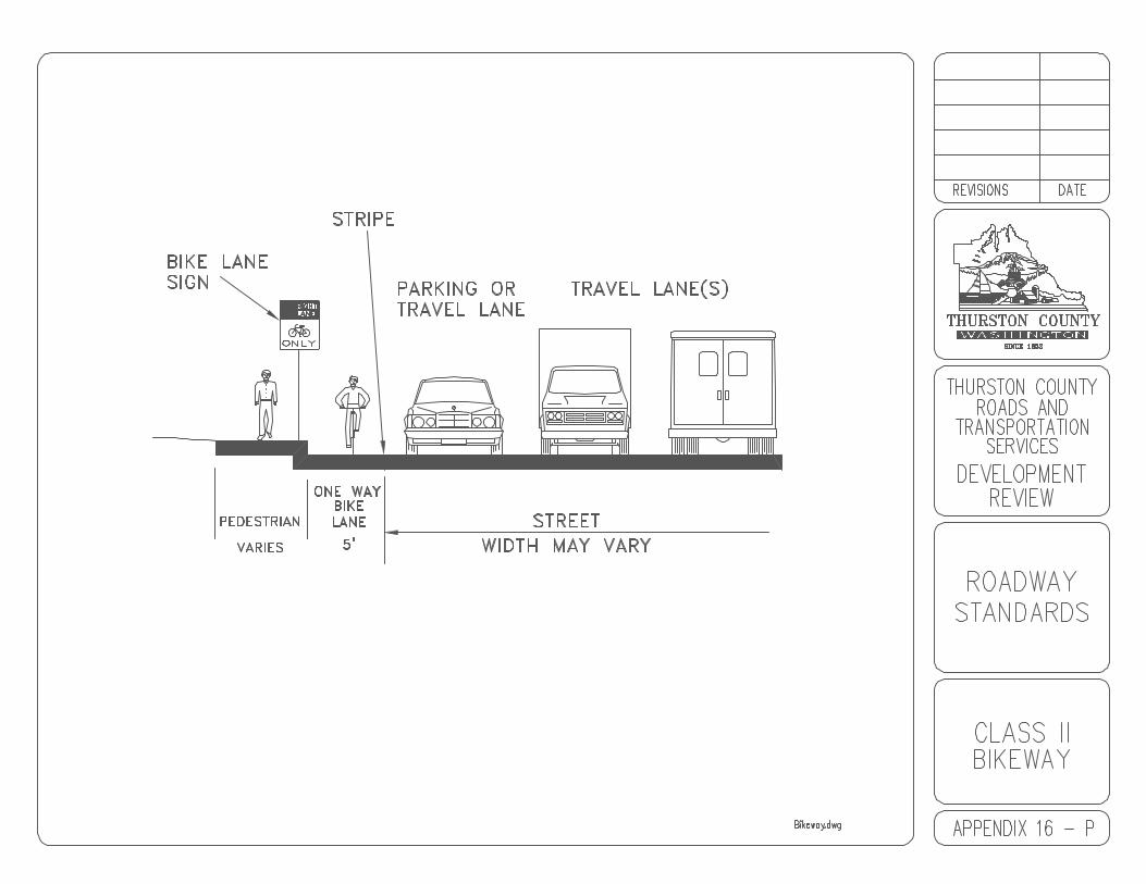
16.01 General16.02 Design Standards16.03 Sidewalks, Curb and Gutter16.04 Cement Concrete Curb and Gutter16.05 Curb Access Ramps16.06 Staking16.07 Testing16.08 Bikeways
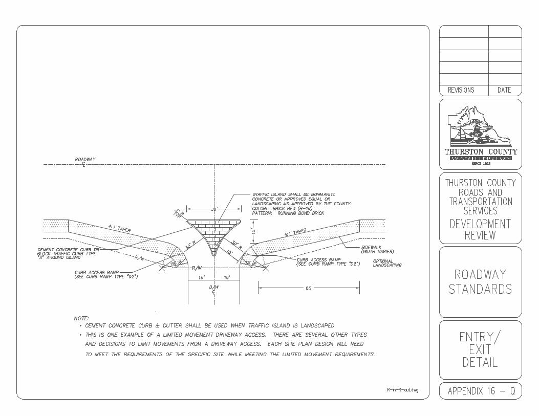
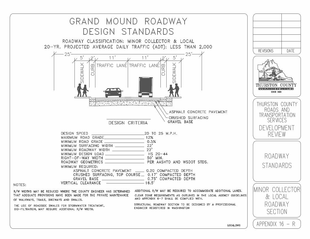
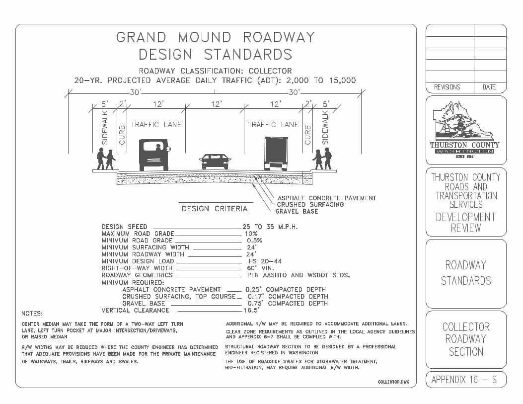
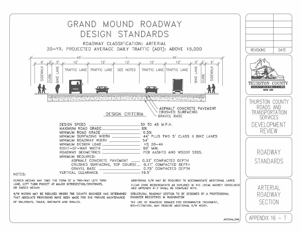
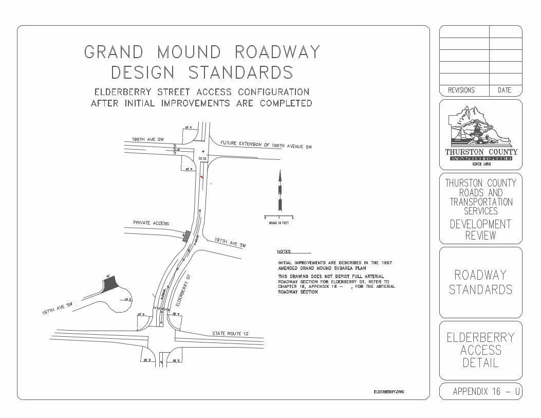
Appendix 16 - A Cement Concrete DrivewayAppendix 16 - B SidewalkAppendix 16 - C Cement Concrete Curb, Gutter and WalkAppendix 16 - D Expansion Joint and Score MarksAppendix 16 - E Curb Ramp SamplesAppendix 16 - F Curb Ramps Type “A” and “B”Appendix 16 - G Curb Ramp Type “C”Appendix 16 - H Curb Ramp Type “D1"Appendix 16 - I Curb Ramp Type “D2"Appendix 16 - J Curb Ramp Type “E”Appendix 16 - K Curb Ramp Type “F”Appendix 16 - L Curb Ramp Type “G”Appendix 16 - M Cement Concrete Curb and GutterAppendix 16 - N Typical Cross-Walk DimensionsAppendix 16 - O Far-side Bus PulloutAppendix 16 - P Class II BikewayAppendix 16 - Q Entry/Exit DetailAppendix 16 - R Minor Local & Local Roadway SectionAppendix 16 - S Collector Roadway SectionAppendix 16 - T Arterial Roadway SectionAppendix 16 - U Elderberry Access Detail
1- 1
1.00 INTRODUCTION
The Thurston County Road Standards shall be referred to as the "Standards."
These Standards include safety, convenience, drainage, aesthetic values, andeconomical maintenance.
These Standards are not intended to provide for all situations but to be flexible inform and content. They are intended to assist but not substitute for competentwork by design professionals. It is expected that land surveyors, engineers,architects, and contractors will bring to each project the best of their skills.
These Standards are also not intended to unreasonably limit any innovative orcreative effort. However, any variance from these Standards are subject to theapproval of the Engineer based on satisfactory evidence that the proposedvariance will produce an equivalent facility.
1.01 Current Edition of the Standards
The most current edition of these Standards will be available at the PermitAssistance Center of the County Development Services Department. In order toremain current with technology and public needs, these Standards are subject torevisions. It is essential for the holder to keep the manual current with revisionsas they occur.
1.02 Application of Standards
A. Mandatory Standards
Mandatory Standards are those considered most essential to theachievement of overall design objectives. Mandatory Standards use theword “shall”.
B. Advisory Standards
Advisory Standards allow some flexibility in application to accommodatedesign constraints or to be compatible with local conditions. AdvisoryStandards use the word “should”.
C. Permissive Standards
All Standards other than the mandatory and advisory, indicated with theword “may”, are permissive with no requirement intended.
2- 1
CHAPTER 2GENERAL CONSIDERATIONS
2.00 GENERAL CONSIDERATIONS
2.01 Applicability2.02 Definitions2.03 Adopted Thurston County Specifications2.04 Exemptions2.05 Interpretation and Enforcement2.06 Project Acceptance2.07 Time Limitation of Acceptance2.08 Variances from the Standards2.09 Environmental Considerations2.10 Violations and Penalties2.11 Severability2.12 Fees2.13 Transportation Improvements2.14 Grading Permits2.15 Grading Plan2.16 Securities2.17 Withdraw of Approval/Acceptance2.18 Site Maintenance2.19 Correspondence
2- 2
2.00 GENERAL CONSIDERATIONS
2.01 Applicability
Except as noted in Section 2.04, these Standards and guidelines shall govern allnew construction and upgrade construction. Standards shall be consideredreasonable minimum regulations, and shall not be relaxed except upon approvalof a variance.
Any land development which will adversely impact the level of service, safety, oroperational efficiency of abutting or serving roadways or is required by otherCounty code, permit or ordinance to improve such roadways, shall improve thoseroadways in accordance with these Standards or the applicable urban growtharea Standards.
These Standards are pursuant to Thurston County Code Title 18, "Platting andSubdivision" and Title 20, "Thurston County Zoning Ordinance" and the UniformBuilding Code. Where these Standards may be inconsistent with the provisionsof Title 18 and Title 20, these Standards shall control.
2.02 Definitions
AASHTO - American Association of Highway and Transportation Officials.
Acceleration Lane - A speed change lane, including tapered areas, for thepurpose of enabling a vehicle entering a roadway to increase its speed to a rateat which it can more safely merge with through traffic.
Access - A trail, driveway or private road that connects to the general publicroad system.
ACP - Asphalt Concrete Pavement.
ADT - Average Daily Traffic. The total two-directional volume of traffic passingthrough a given point during a given time period, divided by the number of daysin that time period. When used as a threshold to determine classification (size)of the access point or road, ADT shall be based on the ultimate build out of allland, considering current zoning, that will potentially be served by the accesspoint or road.
Applicant - Any person, firm, partnership, association, joint venture, corporationor any other entity responsible for a given project seeking approval from theCounty for any land use or other related permit or approval referenced inThurston County Code and which requires utilization of these Standards.
Approved/Accepted Plans - Project plans that have been accepted forconstruction by the County Engineer or designee.

2- 3
ATB - Asphalt Treated Base.
Auxiliary Lane - The portion of the roadway adjoining the traveled way forparking, speed change, turning, storage for turning, weaving, truck climbing, andother purposes supplementary to through-traffic movement.
Breakaway Structure or Breakaway Design - A structure or installation thathas been crash tested in accordance with National Cooperative HighwayResearch Program procedures.
Capacity - The maximum number of vehicles that have a reasonableexpectation of passing over a given roadway or section of roadway in onedirection during a given time period under prevailing roadway and trafficconditions.
CF - Cubic Feet.
Channelization - The separation or regulation of conflicting traffic movementsinto definite paths of travel by the use of pavement markings, raised islands orother suitable means to facilitate the safe and orderly movement of both vehiclesand pedestrians.
Clear Zone - The total roadside border area, starting at the edge of traveledway, available for safe use by errant vehicles. This area may consist of ashoulder, a recoverable slope, a nonrecoverable slope, and/or a clear run-outarea. The desired width is dependent upon the traffic volumes, speeds, and theroadside geometry.
CMP - Corrugated Metal Pipe.
Control Zone - That roadside area defined by the “Control Zone DistanceTable”, found in the WSDOT Utilities Manual, within the road right-of-way inwhich placement of utility objects are controlled.
County - Thurston County
CSTC - Crushed Surfacing Top Course.
Cul-de-sac - Short road having one end open to traffic and the other temporarilyor permanently terminated by a vehicle turnaround.
CY - Cubic Yard.
Deceleration Lane - A speed change lane, including tapered areas, for thepurpose of enabling a vehicle that is to make an exit turn from the roadway toslow to a safe turning speed after it has left the main stream of faster movingtraffic.
2- 4
DHV - Design Hour Volume. Hourly peak traffic volume, in a typical 24 hourperiod, used for road design and capacity analysis.
Design Speed - A speed determined for design and correlation of the physicalfeatures of a highway that influence vehicle operation: the maximum safe speedmaintainable over a specified section of road when conditions permit designfeatures to govern.
Director - The Director of Thurston County Roads and Transportation Servicesor authorized representative.
Driveway - Access to individual lot.
Easement - A right to use or control the property of another for designatedpurposes.
Edge of Traveled Way - The face of curb or roadside edge of bike path forroads that are, or will be constructed to urban Standards, or the edge of drivinglane (not shoulder) for roads that are, or will be constructed to rural Standards.
Encroachment - Occupancy of County right-of-way by non-roadway structuresor other objects of any kind. This includes any work within the County right-of-way.
Engineer - Shortened designation for County Engineer or authorizedrepresentative. This definition shall also be applied to the terms “Director” or“Engineer” as they may appear in the Standard Specifications or the StandardPlans.
Geometrics - The arrangement of the visible elements of a road such asalignment, grade, sight distance, widths, and slopes.
Grade - Rate or percent of change in slope, either ascending or descending fromor along the roadway. It is measured along the centerline of the roadway oraccess point.
Half Road - A road constructed along the property line of development utilizinghalf the regular width of the right-of-way and permitted as an interim facilitypending construction of the other half of the road by the adjacent owner.
Hazard - A side slope, an object, water, or a drainage device which, if impacted,would apply unacceptable impact forces on the vehicle occupants or placeoccupants in a hazardous position. It may be either natural or manmade.
Horizon Year(s) - Estimated year or years in which a project or phases of aproject will be complete.
2- 5
Intersection - The general area where two or more roadways join or cross. Minor approaches to roadways such as private driveways are also defined as anintersection.
Island - A defined area between traffic lanes for control of vehicle movementsand/or for pedestrian refuge.
Joint Access - An access onto County right of way which provides access to twodriveways.
Land Surveyor - A professional land surveyor currently licensed by the State ofWashington.
LF - Linear Feet.
Median - That portion of a divided roadway separating the traveled ways fortraffic in opposite directions.
MPH - Miles Per Hour.
NGVD - National Geodetic Vertical Datum
Operating Speed - Used for determination of sight distance. Operating speedshould be equal to the P85 speed for existing facilities and be equal to thedesign speed for new facilities.
Passing Sight Distance - The minimum sight distance required for the driver ofone vehicle to pass another vehicle safely and comfortably.
Pavement Width - The distance measured from face of curb to face of curb forcurbed sections of roadway or the distance measured from outside edge ofpavement to outside edge of pavement sections of roadway.
PC - Point of Curvature.
PCC - Portland Cement Concrete.
PI - Point of Intersection.
Plan/Construction Drawings - The plans, profiles, cross sections, elevations,details, and supplementary specifications, signed by a licensed professionalengineer and accepted by the County Engineer, which show the location,character, dimensions, and details of the work to be performed.
Posted Speed - Is the speed actually signed along the roadway.
2- 6
Private Road - Private vehicular access provided for by an access tract,easement, or other legal means, serving two or more potential dwelling units;privately owned and maintained.
Project Engineer - A professional engineer currently licensed by the State ofWashington, retained by the applicant, and acting on the applicant’s behalf as aproject designer.
PT - Point of Tangency.
Public Road - Publicly owned and maintained road.
P85 Speed or 85th Percentile (85%) Speed - Based on speed studies, P85Speed is that speed at which 85% of the vehicles travel at or below.
Radius Return Access Point - The intersection of an access point with aCounty road delineated by either pavement edges or curbs laid out at each edgein curvilinear fashion between tangents formed by the edge of roadway (or curbface) and the edge of access point (driveway) pavement or curb face.
R/W/Right-of-Way - All property in which the County has any form of ownershipor title and which is held for public road purposes, regardless of whether or notany road exists thereon or whether or not it is used, improved, or maintained forpublic travel.
Road/Roadway - An open public way for the passage of vehicles, person andanimals. Limits include the outside edge of sidewalks, or curbs and gutters, orside ditches, including the appertaining shoulder and all slopes, ditches,channels, waterways, and other features necessary for proper drainage andprotection within the right-of-way or easement.
Rural Areas - Areas so designated in Thurston County Comprehensive Plan,and as implemented through community plans and area zoning which arecharacterized by long-term low density development.
Separate Turn Lane - An auxiliary lane for turning traffic in one direction whichhas been physically separated from the intersection area by a traffic island orstripe. Separate turn lanes may be included within intersections or separatedfrom intersection areas by traffic islands.
SF - Square Feet.
Shoulder - That portion of the roadway contiguous with the traveled way foraccommodating stopped vehicles, for emergency use, and for lateral support ofbase and surface courses.
2- 7
Sight Distance, Stopping - As defined by AASHTO, the minimum distancealong a roadway sufficiently long enough to enable a vehicle traveling at or nearthe design speed to stop before reaching a stationary object in its path. TheStopping Sight Distance is the sum of the distance a driver travels to perceiveand comprehend the object, decide on an appropriate response, react andcomplete the braking maneuver without hitting the object in its path.
Speed Change Lane - A separate lane for the purpose of enabling a vehicleentering or leaving a roadway to increase (acceleration lane), or decrease(deceleration lane) its speed to a rate at which it can more safely merge with ordiverge from through traffic.
Traveled Way - The part of the road made for vehicle travel excluding shouldersand auxiliary lanes.
Trip - A one-direction movement which begins at the origin and ends at thedestination.
Trip Distribution - The process by which the movement of trips between zonesis estimated. The data for each distribution may be measured or estimated by agrowth factor process or by a synthetic model.
Trip End - A single or one-direction vehicle movement with either the origin orthe destination (exiting or entering) inside the study area. For trip generationpurposes, the total trip ends for a land use over a given period of time are thetotal of all trips entering plus all the trips exiting a site during a designated timeperiod.
An example of a trip end would be: A site which has over some period of time,2,000 trips entering and 1,800 trips leaving, has 3,800 trip ends associated withit. The 3,800 total trips to and from the site represent a total of 7,600 trip ends. Of these, 3,800 occur at locations other than the site in question.
Trip Generation - A general term describing the analysis and application of therelationships that exist between the trip makers, the traffic study area, and thetrip making. It relates to the number of trip ends in any part of the traffic studyarea.
Unopened Right-of-Way - A County right-of-way that exists by dedication ordeed, but for which no vehicular roadway has been constructed by the County orother parties.
Urban Areas - Areas so designated in the Thurston County ComprehensivePlan, and as implemented through community plans and area zoning which arecharacterized by denser commercial/industrial and residential development.
2- 8
Utility - A business providing public service such as gas, electric power,telephone, telegraph, water, sewer, or cable television, whether or not suchbusiness is privately owned or owned by a governmental entity.
2.03 Adopted Thurston County Specifications
Except where these Standards provide otherwise, or by contract with the County,all design and construction, including materials, shall be in accordance with therelevant sections of the following publications:
A. Washington State Department of Transportation "Standard Specificationsfor Road, Bridge, and Municipal Construction”, current edition, hereinafter“Standard Specifications.”
B. Washington State Department of Transportation "Standard Plans forRoad and Bridge Construction", current edition, hereinafter “StandardPlans.”
C. Washington State Department of Transportation “HydraulicsManual”, current edition.
D. Washington State Department of Transportation “ConstructionManual”, current edition.
E. U.S. Department of Transportation "Manual on Uniform Traffic ControlDevices, as amended and approved by the Washington State HighwayCommission", current edition, hereinafter “MUTCD.”
F. Drainage Design and Erosion Control Manual for Thurston County,Washington, current edition, hereinafter “Drainage Manual.”
G. Washington Chapter American Public Works Association "StandardSpecifications for Municipal Public Works Construction", current edition,hereinafter "APWA Standard Specifications."
H. "Standard Specifications for Highway Bridges," current edition, adopted bythe American Association of State Highway and Transportation Officials,hereinafter "AASHTO Bridge Specifications."
I. "Washington State Department of Transportation Design Manual", currentedition, hereinafter "WSDOT Design Manual."
J. Washington State Department of Transportation "Local AgenciesGuidelines", current edition, hereinafter “LAG Manual.”
K. Washington State Department of Transportation “Traffic Manual”, currentedition.

2- 9
L. "A Policy on Geometric Design of Rural Highways," published byAASHTO, current edition.
M. "Trip Generation Manual," published by Institute of TransportationEngineers, current edition.
N. “AASHTO Guide for Design of Pavement Structures,” published byAASHTO, current edition.
O. “Uniform Building Code”, current edition, hereinafter “UBC.”
2.04 Exemptions
These Standards shall not govern the following:
A. Maintenance work within public rights-of-way by County forces.
B. Temporary repairs made on an emergency basis.
C. 3R Standards - Restoration, Rehabilitation, and Resurfacing as defined inthe LAG Manual.
D. Rural private road, if:
1. The road complies with requirements of the 16-foot privateroadway section, Appendix 6-A. To determine whether the roadcomplies, pot-holing and material testing may be required; and
2. Engineered drainage plans are not required; and
3. Existing grade or slope in the road profile does not exceed 12%;and
4. The work will not intercept a drainage swale or otherwise impactnatural surface drainage; and
5. Roadway runoff will not affect neighboring property.
E. Upgrading of existing private road, if:
1. Existing road meets the requirements of the 16-foot privateroadway section, Appendix 6-A; and
2. Road is to remain private; and
3. No safety improvements are required by Engineer or designee.

2- 10
4. Roads between 12 and 16-feet in width and serving 4 or fewer lotsmay be allowed with pullouts every 300 feet. The pullouts shall bea minimum of 8 feet in width and 50 feet in length plus 25 foottapers at each end. “No Parking-Fire Lane” signs shall also beplaced at each end of the pullout.
2.05 Interpretation and Enforcement
Interpretation and enforcement of these Standards shall be the responsibility ofthe Engineer.
Failure to comply with these Standards will be cause for withholding orwithdrawing acceptance of plans or drawings, withholding of bond, finalinspection approval or occupancy certificates and/or other penalties asprovided by code, ordinance or law.
2.06 Project Acceptance
The Engineer shall rely upon the certification and approval of the road anddrainage plans and calculations by the applicant’s Project Engineer for approvalof the project. The Engineer’s acceptance of the plans shall not relieve theapplicant or the applicant’s Project Engineer from any liability related to portionsof the design which are not in conformance with these Standards or do not followgood engineering practice.
Upon receipt of the project plans and calculations, the Engineer will review thework of the applicant’s Project Engineer for accuracy and completeness. Theplans and calculations will either be accepted by the County or returned forrevisions. All revisions are subject to hourly review fees as set forth in thecurrent Thurston County Fee Schedule. Project acceptance occurs when theEngineer signs the plans.
The plans, reports, basin maps and calculations shall be signed, sealed anddated by the applicant’s Project Engineer. The cover sheet of the plan set andthe cover sheet of all calculations shall bear the certification which reads:
“The design improvements shown in this set of plans and calculations conform tothe current edition of the Thurston County Road Standards and the DrainageDesign and Erosion Control Manual for Thurston County. All design varianceshave been approved by the Thurston County Engineer. I approve these plansfor construction.”
2.07 Time Limitation of Acceptance
The acceptance of plans shall be valid for a time period of 2 years from the dateof acceptance by the Engineer. Construction in accordance with the approvedplans must be completed within this time period. If not completed within this time
2- 11
period, then the plans shall be resubmitted to the County for review and anyrevisions or modifications necessary to meet the current Standards shall bemade. Re-submittal fees equal to new application fees shall be paid before theplans are approved by the County.
A Traffic Impact Analysis shall only be valid for a time period of 2 years from thedate of submittal. If the project is not completed within 2 years from submittaldate, the Traffic Impact Analysis shall be updated and resubmitted to the Countyfor review and concurrence prior to project acceptance. Re-submittal fees equalto new application fees shall be paid before the plans are approved by theCounty.
2.08 Variance from the Standards
A. These Standards represent reasonable approaches based on pastexperience in Thurston County and other jurisdictions. TheseStandards indicate the appropriate practice under most conditions.
B. Engineering design is an endeavor that examines alternativesolutions in real world situations and accordingly, these Standardsare not provided to hamper the introduction of new ideas. It is fullyexpected that creative engineering will continue to take place. Situations will present themselves where alternatives may bepreferred to allow conformance with existing conditions, toovercome adverse topography or to allow for more affordablesolutions without adversely affecting safety, maintainability oraesthetics. These Standards are intended to provide predictabilityyet still allow for the flexibility necessary for innovation.
C. A variance request shall not be evaluated until an application for therequired permit/approval has been applied for.
D. The variance request shall be in writing, submitted to the DevelopmentReview Division and address the following points:
1. Specifically outline the reason for the variance request withalternatives if appropriate.
2. Specify the chapter and section the variance request is for.
3. Provide supporting evidence demonstrating that a variance fromthese Standards is in the public interest, based on soundengineering judgment and that the requirements for safety,function, appearance, fire protection and maintainability are fullymet.
2- 12
E. The above information shall be used by the Engineer in evaluatingrequests for variances from these Standards. The Engineer will endeavorto evaluate and respond in writing to the variance request within 15working days of receipt of the request. Variance requests that do notmeet the Uniform Fire Code also require concurrence from the CountyFire Marshall.
F. Variances made during the construction of a project shall be approvedprior to any changes being made in the field.
2.09 Environmental Considerations
Unless exempt, land development projects, including clearing and gradingactivities, must have an Environmental Checklist completed by the applicant andsubmitted along with plans and other information when approval or permits arebeing requested for a project. In all cases, the applicant is required to adhere tothe requirements in the Critical Areas Ordinance. Permits, project acceptancesand/or approvals shall not be issued until an Environmental Determination hasbeen issued and the appeal period has passed.
2.10 Violations and Penalties
A. Failure to comply with these Standards shall be cause for withholding orwithdrawing approval of plans, forfeiture of financial security or non-acceptance of the work by the County.
B. Any person, firm or corporation violating any provisions of theseStandards shall be deemed guilty of a misdemeanor, and, upon convictionthereof shall be punished by a fine not exceeding $1,000 or byimprisonment for not more than 90 days, or by both such fine andimprisonment. Each person, firm or corporation found guilty of a violationshall be deemed guilty of a separate offense for every day during anyportion of which any violation of any provision of these Standards iscommitted, continued or permitted by such person, firm or corporation andshall be punishable therefore as provided for in these Standards.
C. Notwithstanding the existence or use of any other remedy, the Director orEngineer may seek legal or equitable relief to enjoin any acts or practicesand abate any conditions which constitute or will constitute a violation ofthese Standards or other regulations herein adopted.
2.11 Severability
If any part of these Standards or its application to any person is, for any reason,declared invalid, illegal, or unconstitutional, in whole or in part by any court oragency of competent jurisdiction, said decision shall not affect the validity of theremaining portions hereof.
2- 13
2.12 Fees
Fees shall be assessed in accordance with current Development Services feeschedule as approved by the Thurston County Board of Commissioners.
The applicant shall be responsible for costs incurred by the County for planreview, inspection and quality control.
All plan review and inspection fees shall be paid prior to the applicant receivingsigned road construction mylars.
2.13 Transportation Improvements
Transportation and frontage improvements, SEPA impacts, fees, etc. or theproportionate cost share of the improvements based on peak hour trips andnecessary to mitigate impacts of each phase of development shall be in place orpaid no later than time of final plat approval or certificate of occupancy,whichever occurs first, for that phase. If the improvements are not listed on theCounty Transportation Improvement Plan, they shall be installed prior to final platapproval.
2.14 Grading Permits
Grading Permits are required for all grading activities outlined in the currentlyadopted version of the UBC.
2.15 Grading Plan
All grading activities meeting the requirements outlined in the UBC, shall submita Grading Plan. The Grading Plan may be a part of the project plans forassociated land development and other projects.
2.16 Securities
Under certain circumstances or as required by County code, securities may berequired by the County to guarantee the performance of, or to correct permittedwork. The amount of security shall cover the County's cost to correctdeficiencies. The type and amount of security shall be per ordinance or, if notspecified, be at 150% of the estimated cost of the work. The County mayrequest a Project Engineer's Estimate or contractors bid document of the projectcosts to use in establishing the amount of security.
Types of securities include but are not limited to cash deposits, assignment ofsavings account, irrevocable standby letter of credit and bonds. Securities shallbe released by the County upon satisfactory completion of the required work andsatisfaction of any previously specified stipulations relating to the work beingperformed. The Project Engineer shall provide written certification to the County
2- 14
that the stormwater facilities are functioning and being maintained as intendedby the design prior to the release of all securities for the operation andmaintenance of the stormwater facilities. The applicant shall remain financiallyresponsible for any and all costs exceeding the amount of the original financialguarantee.
2.17 Withdrawal of Approval/Acceptance
At the discretion of the County, errors and omissions in the approved/acceptedplans or information used as a basis for such approvals/acceptances mayconstitute grounds for withdrawal of any approvals/acceptances and/or stoppageof any or all permitted work. It shall be the responsibility of the applicant to showcause why such work should continue, and make such changes in plans thatmay be required by the County before the plans are re-approved.
2.18 Site Maintenance
A. The applicant shall schedule and control the work so as to complywith all applicable provisions of County land use codes andapplicable state and federal laws and regulations to prevent anyhazards to public safety, health and welfare.
B. On existing roads, two way and all existing lanes of traffic shall bemaintained at all times unless detour plans have been approved inadvance by the Engineer and the Board of County Commissionerswhere applicable.
C. Roads shall be kept free of dirt and debris.
D. Pedestrian and bicycle facilities shall be kept free of obstructions.
E. Pedestrian and vehicular access to occupied buildings shall bemaintained except where written approval from the building ownerhas been obtained.
F. Drainage facilities shall be maintained and fully functionable.
2.19 Correspondence
All correspondence, including letters, reports, and plans, shall be clearly labeledwith the County project number. Submittal or correspondence without thisidentification will not be accepted and will not be reviewed.
3- 1
CHAPTER 3PLAN FORMAT
3.00 PLAN FORMAT
3.01 Submittal Procedure3.02 General Formatting3.03 Plan Elements3.04 Profile Elements3.05 Typical Cross Section3.06 Intersection Plan Details3.07 Drainage and Erosion Control Plan3.08 As-built Drawings3.09 Standard Notes3.10 Construction Staking
Appendix 3 - A Standard Notes
3- 2
3.00 PLAN FORMAT
When construction is required by conditions of a plat, subdivision, Special UsePermit, commercial and other projects or by these Standards, plans for theproposed improvements shall be prepared, meeting all of the requirements inthese Standards. Failure to provide the requirements set out in this chapter shallconstitute an incomplete application and shall not be accepted for review. Theplans shall be signed, sealed, and submitted by the applicant's Project Engineerto the County for review. Final plans and profile drawings must be accepted bythe Engineer prior to the start of construction and recording of the development. The applicant's Project Engineer shall be a registered engineer, licensed in theState of Washington.
3.01 Submittal Procedure
Plans, profiles, and details shall be submitted on sheets 24" by 36".
A. All plan submittal prior to approval shall include the following:
1. Three complete sets of plans, profiles, and details. (Refer toSections 3.02, through 3.08 for plan content requirements.)
2. Two sets of drainage calculations.
B. Upon final design acceptance by the Engineer the following shall besubmitted:
1. One reproducible set of plans, profiles, and details (mylar orvellum) for the Engineer’s signature.
Followed by:
2. Seven complete sets of signed plans, profiles, and details.
C. Changes to signed plans, profiles, and details shall be submitted forreview and acceptance prior to construction. The following shall besubmitted:
1. Three revised sets of plans, profiles, and details.
Followed by:
1. Seven copies of the signed revised plans, profiles, and details.
D. Final submittal shall be a complete set of "as-built" drawings on goodquality reproducible mylar. All changes to the original drawings shall beshown with a single line or XXXX on the as-built drawings. As-builtdrawings shall be submitted prior to final acceptance of any road,
3- 3
structure, drainage or facility for final acceptance by the County. Suchdrawings shall describe any and all revisions or additions to the approvedplans.
3.02 General Formatting
Roadway plan alignments shall be stationed at 100' intervals with “tick marks”between stationing at a minimum of 50' intervals. Road widening projects shallbe stationed at 25' intervals. Stationing shall be shown on all points of curvature,tangents and intersections and shall be tied to existing road surveys, stationing,section corners, quarter corners and the horizontal control net established by theEngineer. Stations should increase from west to east and from south to northand be north arrow consistent, ie. north arrow pointing to the top of the drawingor to the right of the drawing.
3- 4
3.03 Plan Elements
NOTE: ’P - Minimum project requirements for preliminary approval prior topublic hearing.
”P Title Block to include:1. Project name 4. Road Name2. County assigned 5. Designed By:
project number 6. Drawn By:3. Sheet number 7. Checked By:
”P Legend (APWA Standard Symbols).
”P Signature block for acceptance.
”P Project Engineer’s stamp (signed and dated).
”P Section, township, range and vicinity map.
”P Horizontal Scale Bar: 1" = 50' or less, However, 1" = 100' may beoptional for larger developments. Details for clarification shall be shownon a convenient scale.
”P North arrow.
”P Section and lot lines.
”P All topographic features within right-of-way limits or future right-of-waylimits, and sufficient area beyond to resolve questions of setback, slope,drainage, access onto abutting property, and road continuations.
”P Cross sections for all proposed new roads and widening of existing roads.
”P Road alignments and centerline stationing.
”P Curve data including radius, delta, arc length, and semi-tangent on allhorizontal lines. Curve radius only for Preliminary.
”P Project beginning and ending designation with stations.
’P Indication of whether the roads are public or private.
”P Identification of all roads and adjoining subdivisions.
”P Edge of pavement and width.
”P Sidewalks and width.
3- 5
”P Easement type, width and ownership.
”P Right-of-way lines and width for proposed road and intersecting roads,together with existing road improvements with dimensions.
”P Cut and fill quantities.
”P Existing and proposed drainage features, indicating direction of flow, typeof each drainage channel, pipe, and structure.
NOTE: Drainage facility sizing required on sites with critical areas andhigh ground water table.
’P Identify roof run-off and storage.
’P Soil test pit locations.
”P All proposed utilities that will be designed and constructed.
’P Existing and proposed transit stops and shelters, and bus pullouts.
’P Environmentally sensitive and critical area.
’P Existing and proposed wells within 200 feet of property lines.
’P Existing drain fields.
” Bearings on road centerline, keyed to an associated plat map.
” Stationing of PC, PT, PI, Equations and Intersections.
” Datum - Bench mark elevation and location (on all sheets whereelevations are referenced).
” Finished grade elevations shall be shown on:
1. All radius returns at beginning, quarter points and end.
2. All cul-de-sacs at beginning, quarter points and end.
’ Existing center line and gutter line grades for all frontage improvements.
” All existing utilities.
” Traffic control signing and signal layout.
” Pavement marking details with station and offsets.
3- 6
’ Size, invert in, invert out, rim elevations, station of structures and offsetsfor all drainage facilities and other requirements as specified in theDrainage Manual.
” As a minimum, one new control monument shall be set at each end of anew road and intermediate monuments as required. Road monumentsshall not be placed in landscape medians. Witness monuments shall beoffset in the roadway and so described.
” Beginning, quarter points, and ending elevations of curb returns.
” Temporary and permanent erosion control.
” Grading plans (see UBC for requirements).
” Proposed roadway names.
” Other data necessary for the specific project.
3- 7
3.04 Profile Elements
Profile elements shall include the following:
” Original ground line along center line, edge of pavement, ditch flow line orarrows, 25-foot stations through superelevation, and at significant groundbreaks and topographic features with accuracy to within 0.1 feet onunpaved surfaces and 0.02 feet on paved surfaces. When a roadextends to the perimeter of the project, ground lines shall be extended atleast 300 feet to show any changes in contour which might affect theprofile of the proposed road.
” Existing and proposed road, sewer, water and storm drainage profile withstationing to show stationing of points of curve, tangent, and inner sectionof vertical curves, with elevations to 0.01 feet.
” Values for grade and length of vertical curve shall be shown with theprofiles on a numbered grid.
” Superelevation data, if required, to include diagrams and calculations,shall be required and included for roadways of 30 miles per hour designspeed or more.
” Vertical datum used on all benchmarks will refer to NGVD 1929 controli.e. mean sea level.
” Vertical scale of one inch equals two to five feet. Vertical scale shall beone inch equals ten feet if the optional one inch equals 100 foot horizontalscale is used.
3.05 Typical Cross Section
”P Widths of pavement, shoulders, walks, ditch and right-of-way.
”P Type of road.
”P Depth of gravel base, crushed surfacing and hard surfacing.
”P Type of sub-grade soil.
”P Slope of crown, shoulder and ditch design.
”P Total width from centerline to back of ditch, including width of newpavement on widening of existing roads.
3- 8
”P A separate, full-width roadway typical section for each road or portion ofroad having a different section, labeled with appropriate stationing (i.e.Sta. 10+00 to Sta. 12+36).
” R-value table, if applicable, or other relevant information from Chapter 6.
” Location of existing and proposed utilities.
” All other data necessary for a specific project.
3.06 Intersection Plan Details
” When either of the road centerline profile grades within 35 feet of anintersection have a gradient less than or equal to 1% or greater than orequal to 8%, an intersection detail drawn to a scale of 1" = 20' must beincluded as a detail on the plans. The detail will show spot elevationsevery 25 feet on the road centerline, around the radius return and grateelevations for drainage structures in the intersection. The intersectionplan must be clearly detailed to show flow line grades and how surfacedrainage will be controlled at the intersection. Radius return data forlesser gradients shall be shown on the road drawings.
” Details meeting the Americans with Disabilities Act (ADA) requirements.
” Profile grades for all roads (public and private) intersecting onto a Countyroad (existing or proposed) shall be designed and constructed so thatintersection sight distance is available at the intersection. Refer toSection 4.04.
3- 9
3.07 Drainage and Erosion Control Plan
Submittal shall be in accordance with the Drainage Design and Erosion ControlManual for Thurston County.
3.08 As-Built Drawings
Engineering as-built or record drawings for roads and drainage facilities will berequired prior to final inspection approval. In some cases, these drawings will berequired during the inspection process to approve facilities before the next phaseof construction can proceed.
3.09 Standard Notes
All plans shall contain, as applicable, the Standard Notes listed in Appendix 3-A. Other notes should be added as appropriate and necessary.
3.10 Construction Staking
So as to ensure that design is carried through to the final product, constructionstaking of the Project Engineer's design by a registered surveyor or the designengineer, is required. Construction staking will consist of, but not limited to, thefollowing:
A. Easement/Right-of-Way linesB. Slope Stake Sub-GradeC. Catch basins prior to Sub-Grade sign offD. Gutter lineE. Top of Sub-GradeF. Top of Gravel BaseG. Top of Crushed Surfacing, if requiredH. DrainageI. 50 foot center line stations minimumJ. Quarter Points on Cul-de-Sacs.
Staking location shall be determined by the County at the pre-constructionconference.
Appendix 3 - A
APPENDIX 3-ASTANDARD NOTES
A. All materials and workmanship shall be in accordance with the requirements ofthe most current edition of the State of Washington, Department ofTransportation Standard Specifications for Road and Bridge Construction andThurston County Road Standards.
B. Inspection of the storm drain system must be called for before any backfill isplaced for the drain system.
C. Catch basins shall be Type 1 with B-2a, WSDOT Standard Plans, frame andgrate unless otherwise noted. The outside edge of the catch basin shall beplaced at the intersection of the curb and gutter and 0.010' to 0.015' belowfinished grade, or in the gutter line of the rolled edge section.
D. If adequate inspection is not called for before completion of the roadwayconstruction, it may be necessary for core drilling and testing to be performed toassure an acceptable quality of roadway. When core drilling is found to benecessary, the applicant will be held responsible for all costs incurred.
E. It will be the applicant’s responsibility to contact all utility companies in order toassure that all lines, pipes, poles and other appurtenances are properly locatedand their installation is coordinated with the road construction. All utilityrelocation work shall be at the expense of the applicant and must be inaccordance with Thurston County Road Standards prior to road acceptance.
F. Culvert pipe shall be concrete, aluminum or plastic 12-inch diameter minimumpipe with beveled ends unless otherwise noted. Beveled ends shall be aminimum of 3:1 in the ditch line or match the slope in a cut or fill section.
G. Buried utilities are shown in their approximate location. The applicant shall havethe utilities verified on the ground prior to any construction.
H. Onsite erosion control measures shall be the responsibility of the applicant andbe in place prior to construction. Any problems occurring before final acceptanceby Thurston County and within 24 months thereafter shall be corrected by theapplicant.
I. Any revisions to plans must be made by the Project Engineer and approved bythe County prior to any implementation in the field.
J. All pavement markings shall conform to the requirements of the MUTCD and theThurston County Standard Pavement Marking Details.
K. Before striping takes place the applicant shall contact the Thurston County trafficdivision for coordination of the striping.
Appendix 3 - A
L. A copy of the approved plans must be on the job site whenever construction is inprogress.
M. Thurston County shall be notified 72 hours before construction is started. Theapplicant shall be responsible for scheduling a pre-construction conference withthe County. Other jurisdictions, Project Engineer, utility companies,subcontractors and other necessary parties to the project shall be present at thepre-construction conference.
N. Slopes shall be stabilized to prevent erosion. In case erosion occurs in ditches,ditch lining is to be provided as requested and specified by the County.
O. All Type 2 catch basins over 4 feet in height shall have standard steps.
P. Where newly constructed paving meets existing paving, the applicant shalloverlay and feather new pavement to provide a smooth transition from existing toproposed paving. Application of a thin paint coat of emulsified asphalt shall beapplied to insure proper bonding.
Q. The completed surface of all courses shall be of uniform texture, smooth,uniform as to crown and grade, and free from defects of all kinds. Thecompleted surface of the wearing course shall not vary more than 1/8 inch fromthe lower edge of a 10-foot straightedge placed on the surface parallel to thecenterline. The traverse slope of the completed surface of the wearing courseshall vary not more than 1/4 inch in 10-feet from the rate of traverse slope shownon the plans.
R. Materials sampling and testing shall be at a frequency and magnitude asspecified in the Standard Specifications or determined by the County Engineer. In the case of plat roads, testing and sampling shall be performed by a privatetesting laboratory. Certified test reports shall be furnished for all tests performedby private testing laboratories.
S. All utility work within existing pavement requires a minimum roadwayreconstruction from the centerline, to include grinding the existing pavement andreplacing it with a minimum 0.17' pavement.
4- 1
CHAPTER 4ROAD TYPES AND GEOMETRICS
4.00 ROAD TYPES AND GEOMETRICS
4.01 Functional Classifications in Rural Areas4.02 Functional Classifications in Urban Areas4.03 Maximum and Minimum Grades4.04 Sight Distances4.05 Private Roads4.06 Half Roads4.07 New Driveways4.08 Emergency Turnarounds4.09 Intersections4.10 Medians and Planters4.11 One-way Roads4.12 Dedications4.13 Railroad Grade Crossings4.14 Traffic Control4.15 Exception to Paving on Rural Local Roads4.16 Slope, Wall, and Drainage Easements4.17 Road Network Circulation4.18 On-Site Principles4.19 Dead End Roads4.20 Roadside Obstacles
Appendix 4 - A Vision Clearance Triangle
4- 2
4.00 ROAD TYPES AND GEOMETRICS
Each lot shall be served by a road built to applicable County Standards set forthherein, as now or hereafter amended, for public or private roads.
For the purpose of determining the applicable standard for development, thedensity and type of land use shall be that designated on the application by theapplicant or, if the applicant fails to designate densities, they shall be deemed tobe the maximum density allowed by the applicable zoning classification or theComprehensive Plan. The applicable Standards shall be determined by thenumber of vehicle trips per day identified as being reasonably anticipated for theproposed use.
In the event an applicant seeks a building permit after the final plat approvalwhich results in a greater density or different use than the original approval, theapplicant shall not be granted the building permit until the road serving the lot isbuilt to the higher standard or an agreement guaranteeing such construction isaccepted by the County.
4.01 Functional Classifications in Rural Areas
All development in the rural areas shall be constructed as set forth in theseStandards.
4.02 Functional Classifications in Urban Areas
A. Olympia
All roadway construction and improvements within the Olympia UrbanGrowth Boundary shall comply with Chapter 15.04.086 Thurston CountyCode.
B. Lacey and Tumwater
All roadway construction and improvement within the Lacey andTumwater Urban Growth Boundaries shall comply with the more stringentof the Standards of the city and the County.
C. Grand Mound, Tenino, Yelm, Rainier, and Bucoda
All roadway construction and improvements within the Grand Mound, Tenino, Yelm, Rainier and Bucoda’s Urban Growth Boundaries shallcomply with urban requirements as set forth in these Standards or asmodified by the Thurston County Comprehensive Plan and the 1997amended Grand Mound Sub Area Plan.
4- 3
4.03 Maximum and Minimum Grades
Grades exceeding the maximum grades specified in Appendices 6-A through 6-G shall require approval by the Engineer, the County Fire Marshal and the FireChief of the local district upon a showing that no practical alternative exists.
Gutter, ditch and swale flow line grades shall not be less than 0.5%.
Refer to Chapter 7 for access grade requirements.
4.04 Sight Distance
A. Stopping Sight Distance
All stopping sight distance calculations shall be based on AASHTO wetpavements criteria with adjustments for downgrades.
B. Intersection Sight Distance
Refer to AASHTO Chapter IX, Sight Distance, Intersection Control.
C. Preserving Sight Distance
Notes outlining the requirements shown in Appendix 4 - A may berequired on final plat restricting the uses of the sight distance triangle withregards to structures, landscaping, fencing, signs, and other visualobstructions.
4.05 Private Roads
A. While community road requirements are usually best served by publicroads, owned and maintained by the County, private roads may beappropriate for some local access roads for either residential orcommercial properties.
B. Private roads are approved only when they are:
1. Permanently established by tract or easement providing legalaccess to each affected lot, dwelling unit, or business and sufficientto accommodate required improvements, to include provision forfuture use by adjacent property owners when applicable; and
2. Built to County Standards, as set forth herein; and
3. Accessible at all times for emergency and public service vehicleuse; and
4- 4
4. Not obstructing, or part of, the present or future publicneighborhood circulation plan developed in processes such as theThurston County Comprehensive Plan, applicable community plan,or Capital Improvement Program; and
5. Not needed as public roads to meet the minimum roadrequirements of these Standards; and
6. Designed to serve a maximum potential of 16 legal lots when theentire length of the private road system to the nearest public road isconsidered. The maximum potential is the number of dwelling unitsthat can possibly be served by the road when physical barriers,zoning or other legal constraints are considered; and
7. Maintained in accordance with these Standards by a capable andlegally responsible owner or homeowner's association or otherlegal entity made up of all benefitted property owners; and
8. Clearly described as a private road on the face of the plat; and
9. Clearly signed at road location as a private road the maintenanceof which the County is not responsible for.
C. The County shall not accept private roads into the County road system until the private road meets all of the requirements of these Standards. This includes, but not limited to, plan and profile drawings, surveymonumentation, dedication of right-of-way and drainage easements. Formore specific information regarding the dedication process, contact theCounty Right-of-Way Section.
4.06 Half Roads
A half road may be permitted subject to approval by the Engineer when:
1. There is reasonable assurance of obtaining the prescribed additionalright-of-way from the adjoining property suitable for completion of a full-roadway; and
2. Such alignment is consistent with or will establish a reasonable circulationpattern; and
3. The right-of-way width of the half road shall equal at least 30 feet, or 50percent of the required right-of-way, whichever is greater; and
4. The traveled way shall be surfaced the same as the designated roadclassification to a width not less than 20 feet; and

4- 5
5. The half road shall be graded consistent with the centerline of the ultimateroadway section.
4.07 New Driveways
A. An emergency vehicle access road with a minimum width of 10 feet with 1foot of clearance on each side shall be provided to Group R Division 3occupancies, as defined by the UBC, that have an exterior wall of the firststory of the dwelling located more than 150 feet from fire apparatusaccess as measured by an approved route around the exterior of thebuilding.
B. The emergency vehicle access road shall be constructed with an allweather surface to adequately support the proposed loads of emergencyvehicles.
C. The maximum grade for a driveway shall be 15%.
D. Turnarounds shall be required for any required emergency vehicle accessroad exceeding 300 feet in length. Turnarounds shall meet one of thefollowing:
1. A looped turnaround providing the required width and turningradius, or
2. A cul-de-sac or hammerhead meeting the requirements ofAppendix 6-G.
E. All turns shall have a minimum inside turning radius of 25 feet.
F. An unobstructed vertical clearance of not less than 13 feet 6 inches inheight shall be maintained for the required width of the emergency vehicleaccess road including required clearance.
G. Bridges shall follow the criteria in Chapter 10 with one exception: A bridgeserving only one single-family dwelling may have a driving width of 8 feet6 inches with hub rails or guard rails.
H. The emergency vehicle access road shall be shown on the site plan.
I. The emergency vehicle access road shall be maintained in accordancewith these Standards by the property owner.
J. The Director of Development Services is authorized to approve alternativematerials or methods, or to modify these driveway Standards pursuant tothe provisions of sections 103.1.2 and 103.1.3 of the Uniform Fire Code.
4- 6
K. 1. Where practical difficulties prevent compliance with theseStandards and where alternative materials or methods do notprovide equivalent protection, the Director of Development Servicesshall provide written notice to the fire district in which the affectedproperty is located.
2. A property owner may elect to not comply with Section 4.07. Insuch cases, the property owner shall sign a statementacknowledging that lack of compliance may impede access ofemergency services to the affected property. Said statement shallbe recorded by the Development Services Department with theCounty Auditor against the parcel number. A copy of suchrecorded statement shall be mailed to the fire district in which theaffected property is located.
4.08 Emergency Turnarounds
A. A cul-de-sac shall be required on any dead end access road over 150 feetin length serving two or more parcels. A hammerhead may be used as atemporary emergency turnaround. Refer to Appendix 6 - G for specificdetails.
B. An emergency turnaround shall be provided within three hundred (300)feet of the end of an existing, private or public, dead end road.
4.09 Intersections
A. Angle of Intersection Minimum 75E to Maximum 105E
B. Minimum Centerline Radius (2-Lane) 55 Feeti
C. Minimum Curb Radius 35 Feeti
D. Minimum Property Line Radius 25 Feeti
i Values shown are for local roads only. All others shall be designed for thespecific roadway section.
E. Minimum centerline offsets between adjacent intersections shall be asfollows:
1. Principle Arterial 1,000 Feet2. Minor Arterial 500 Feet3. Collector 300 Feet4. Local Road 150 Feet
4- 7
F. On sloping approaches at an intersection, landings/apron lengths shall beprovided with grades as specified in Appendix 7-B.
G. Sight Distance
Refer to AASHTO Chapter IX, Sight Distance, Intersection Control.
4.10 Medians and Planters
Optional design feature. Median width shall be additional to, not part of, thespecified width of traveled way. Edges shall be similar to outer road edges:either rolled edge or formed vertical curb; or shoulder and ditch; except thatmedian shoulders shall be minimum four feet in width. Medians shall bedesigned to accommodate pedestrian crossings at intersections, at mid-blockcrosswalks and bus stops. Median and planters may be grassed, landscaped, orsurfaced with aggregate or pavement. They shall be designed so as not to limitturning radii or sight distance at intersections. Maintenance of the medians,planters and planter strips within County right-of-way shall be the responsibility ofthe home owners.
On five lane arterial roads, refuge islands for pedestrians shall be incorporatedas part of the road improvement as determined by the County.
4.11 One-Way Roads
Local roads, including loops, may be designated one-way upon a finding by theEngineer that topography or other site features make two-way traffic impractical.One-way roads shall meet the minimum fire access requirements.
4.12 Dedications
A. Right-of-Way dedication at a minimum shall be in accordance with theapplicable standard roadway section as set out in Appendices 6-A through6-G to accommodate motorized and non-motorized transportation,parking, utility and buffer requirements.
B. Easements shall be provided for all public systems as required.
C. The Engineer may require the dedication of additional right-of-way as acondition of project approval to provide the necessary right-of-way for theextension of existing and future roads for compatibility with the area'scirculation system.
D. Fees shall be assessed for roadway dedications based on the PublicRoads Inspection and Plan Review fee schedule.
4- 8
4.13 Railroad Grade Crossings
All proposed railroad crossings shall be submitted and approved by the railroadand the Utilities and Transportation Commission prior to construction drawingapproval. Additional railroad crossings, especially across main line track, shallnot be considered if alternate access is available.
4.14 Traffic Control
A. Any construction proposed within the traveled way shall provide a TrafficControl Plan. All traffic control and traffic control devices shall be asspecified in the latest edition of the MUTCD. The applicant shallimplement the approved plan, when necessary, until the project is givenfinal acceptance by the County. If conditions change, the traffic controlplan shall also reflect the changes.
B. During any construction, barriers and warning signs shall be erected,lighted and maintained as necessary or as directed by the County for theprotection of the traveling public. The County may hire or use Countyforces to bring traffic control up to the safety Standards set out in theMUTCD, WSDOT Design Manual and other applicable documents at theapplicant’s expense when the safety of the traveling public is at risk.
C. When road closures and detours cannot be avoided, the applicant shallnotify the County at least 7 days prior to the road closure. Road closuresrequiring action by the Board of County Commissioners shall require aminimum of 21 days advance notice. The County requires a detour planto be prepared, submitted and approved prior to closing any portion of aCounty roadway.
The road closure plan, as a minimum, shall include a detour route with thelocation and type of signs to be used, as per the MUTCD. A writtenstatement describing the detour route, length of detour and proposeddates and times of road closure shall also be submitted.
All road closures shall be consistent with Chapter 47.48 RCW. Specialconsideration needs to be given by the applicant concerning the timingrequirements of road closures as specified in the RCW and the timingrequirements for the Board of County Commissioners to review andapprove the closure.
4.15 Exception to Paving on Rural Local Roads
Refer to Section 6.01, Surfacing Requirements
4- 9
4.16 Slope, Wall, and Drainage Easements
Either the functional classification or particular design features of a road maynecessitate slope, wall, or drainage easements beyond the right-of-way line. Such easements may be required of the developer by the Engineer inconjunction with dedication or acquisition of right-of-way.
4.17 Road Network Circulation
The importance of good road network circulation for the health, welfare andsafety of the public cannot be overemphasized. Poor circulation addsunnecessary miles to pedestrian and trail systems, school bus routes, maildelivery and other service deliveries, utility services and most importantly,emergency services such as police and fire. Through good road networkcirculation, the public will have better emergency access and police and firesafety will be enhanced. See also Section 4.19, Dead End Roads.
A. Plans will be reviewed for the provision of the best possible road networkcirculation. The road alignment may necessitate re-alignment in order tofoster the long range transportation objectives of the County. Thisincludes greater scrutiny to provide continuity of pedestrian and other trailsystems related to the proposed road network.
B. To facilitate the best possible road network circulation, if it is determinedby the Engineer, after making an individualized determination, that thelayout of roads are to provide for the continuation of existing roads inadjoining subdivisions, then the roads shall be constructed prior to finalplat approval. When adjoining property is not subdivided, the Engineershall determine whether roads in the proposed plat are to provide accessto such unplatted property. The location for access to unplatted propertyshall be placed such that the objectives in these Standards can beachieved.
C. If the roads are to remain private, the above still applies except aneasement will be shown on the final plat map and they will not bededicated to the public. Specific information in the recorded covenantsregarding the use of this easement will be required.
4.18 On-Site Principles
An integral part of an overall traffic study relates to basic site planning principles. An integrated on-site roadway system should deliver vehicles from the externalroadway system in a manner easily understood by typical drivers and thatmaximizes efficiency, accommodates anticipated traffic patterns and ensurespublic safety.
4- 10
A. Internal Vehicular Circulation
1. Internal circulation is the means by which vehicular traffic isdelivered between entry points and parking areas, pick-up/drop-offpoints, and service areas, and should be planned to accommodateappropriate future traffic volumes.
B. Access points
Refer to Appendix 7-A.
C. Parking
Parking shall be provided to meet site-generated demands and beconsistent with Title 20 of the Thurston County Code and other planningdepartment policies.
D. Vehicular Queuing and Storage
1. Access drives should provide adequate vehicular exit queuing.
2. Parking areas and access points of small developments should bedesigned so vehicles waiting to exit are aligned perpendicular tothe off-site roadway system.
3. Queuing areas of large developments should be sufficient sovehicles queued at exits do not block internal circulation. Exitsshall be signalized if warranted by the MUTCD at build out.
4. Documentation shall be provided to verify queue lengths forsignalized intersections, on-site queuing reservoirs, and off-site leftand right-turn lanes.
E. Building Service Drives
Building service drives are roadways adjacent to a building and itsentrances, and should be designed with sufficient width to serve as one orall of the following:
1. Fire and/or emergency vehicle access
2. Pedestrian pick-up/drop-off points
Pedestrian crossings and pick-up/drop-off points should be signedand striped to identify the vehicular/pedestrian conflict.
3. Internal circulation
4- 11
4. Recirculation in parking areas
Recirculation aisles shall have sufficient turning radii, clearances,sight distances and signing.
5. Bus passenger pick-up/drop off areas.
F. Pedestrian, Bus, Bicycle, and Handicapped Access Facilities
The overall site plans must consider pedestrians, bus, bicyclists, andhandicapped access facilities.
1. Pedestrian Facilities
Pedestrian connections between public transportation facilities andsite buildings should be integrated into the overall project design.Pedestrian facilities should be designed to reduce the motorvehicle use for trips within the development and between nearbydevelopments.
2. Bus Facilities
Appropriate public transportation facilities, such as passengershelters, ride sharing areas and bus staging areas shall beaccommodated adjacent to service drive and entrance areas; atkey locations along circulation drives; and at major pedestrian focalpoints along the external roadway system as determined theCounty and Intercity Transit.
3. Bicycle Facilities
Facilities for parking bicycles should be provided where bicycle useis expected.
4. Handicapped Access Facilities
Handicapped access shall be provided in accordance with federal,state and County requirements.
G. Service and Delivery Vehicles
Service and delivery vehicles require separate criteria for movement toand from the site:
1. Vehicle turning paths shall be sufficient to accommodate thelargest vehicles anticipated, a minimum single unit truck (SU).
4- 12
2. Service vehicle access points shall have turning paths sufficient toallow service vehicles to enter and exit the site without encroachingupon opposing lanes or curbed areas.
3. External and internal roads shall have sufficient separation for largevehicles to be queued on entry or exit without blocking access toparking spaces or internal roadways.
4.19 Dead End Roads
A. Permanent road ends of 150 feet or less in length (measured from theedge of traveled way of the intersecting road to the end of the road) shallhave a minimum roadway section as specified in the Appendices 6-Athrough 6-E and do not require a cul-de-sac.
Permanent road ends between 150 and 600 feet (measuredfrom the edge of traveled way of the intersecting road to thebeginning of cul-de-sac) shall have a minimum roadway sectionas specified in Appendices 6-A through 6-E and be providedwith a cul-de-sac as shown in Appendix 6-G.
Permanent road ends in excess of 600 feet are discouraged butwill be considered for cases where lots are large and/or difficultterrain exists, provided, the number of single family lots servedby the road does not exceed 25 or the ADT generated from theproperties served by the road does not exceed 250. Theroadway shall have a minimum roadway section as specified inAppendices 6-A through 6-E and be provided with a cul-de-sacas shown in Appendix 6-G.
B. The maximum grade within the cul-de-sac bulb or turnaround shallbe 6 percent in any direction.
C. The Engineer may require off-road walkways to connect a road endat its terminus with other roads, parks, schools, bus stops, or otherpedestrian traffic generators, if a demonstrated need exists. TheEngineer may also require road ends be designed for increasedcirculation and future vehicle access where connection to anexisting road or future road is feasible. A public access easementor tract may be required to the property line.
4.20 Roadside Obstacles
A. WSDOT Clear Zone distances shall be used for evaluation,placement and relocation of roadside features within the Countyright-of-way. Such distances are shown in Appendix 6-F for roadswith posted speed of 35 mph or less.
4- 13
For posted speeds of greater than 35 mph, clear distances arecontained within the WSDOT Design Manual.
B. Existing or new roadside features which could present a hazard tothe public shall be placed outside of clear zone areas unlessjustified to the Engineer's satisfaction by suitable engineeringstudies considering traffic safety, or where shielded by a barrier,placed in an area normally inaccessible to vehicles or utilize abreakaway design. If barriers are required, they shall be designedto AASHTO and WSDOT Standards.
C. Locations of poles shall be compatible with driveways,intersections, and other roadside features (i.e., they shall notinterfere with sight distance, roadway signing, traffic signals,culverts, etc.). Where possible, utility poles and other aboveground appurtenances shall be located outside of the sidewalks orwalkways.
D. Costs of relocating poles or obstacles to achieve these Standardsare the responsibility of the applicant/developer whose projectnecessitates compliance with these Standards. This is notintended to prevent the applicant/developer from making financialarrangements with an appropriate utility or other owner of theobstacle to accomplish removal of the pole or obstacle.

5- 1
CHAPTER 5TRAFFIC ANALYSIS GUIDELINES
5.00 TRAFFIC ANALYSIS GUIDELINES
5.01 Purpose5.02 Level of Analysis5.03 Warrants for a Level I TIA5.04 Warrants for a Level II TIA5.05 Traffic Generation Guidelines5.06 Peak Traffic Hours5.07 Level of Service5.08 Concurrencey5.09 Report Certification5.10 Scoping5.11 Background Study Area Data5.12 Safety Analysis
Appendix 5 - A Level I AnalysisAppendix 5 - B Level I Grand Mound AnalysisAppendix 5 - C Level II Analysis
5- 2
5.00 TRAFFIC ANALYSIS GUIDELINES
Applications for land division and changes of land use shall include sufficientdata to determine the amount of additional traffic generated by the development. Such data shall also be used as a guideline for access road and/or drivewayrequirements.
5.01 Purpose
The purpose of a Traffic Impact Analysis (TIA) is to:
A. Determine the safety impacts a particular development will have on theregional road network;
B. Establish whether the development will meet the County's level of serviceStandards adopted within the County Comprehensive Plan; and
C. Determine mitigating measures necessary to alleviate safety issues and tomeet the adopted level of service Standards.
D. Developments that are small and generate less than 25 AM or PM peakhour trips may be reviewed for concurrency without an in-depth TIA byidentifying influence zones for roads that are approaching or have exceedtheir capacity.
5.02 Level of Analysis
There are two level of traffic analysis, as follows:
A. Level I TIA
Trip Generation and Distribution Study. (Refer to Appendix 5-A for studyrequirements.)
B. Level I TIA - Grand Mound
Trip Generation and Distribution Study. (Refer to Appendix 5-B for studyrequirements.)
C. Level II TIA
Traffic Impact Analysis. (Refer to Appendix 5-C for study requirements.)
5.03 Warrants for a Level I TIA
A complete Level I TIA shall be required if any one of the following warrants ismet:
5- 3
A. The project generates 25 or more PM peak hour trips; or
B. The project requires a SEPA review.
A Level I TIA may be required by the County to determine the need and scope ofLevel II TIA.
A Level I TIA shall be expanded to a Level II TIA if any of the warrants in Section5.04 are met.
5.04 Warrants for Level II TIA
A complete Level II TIA shall be required if the project generates more than 50peak hour trips, and any one of the following warrants is met:
A. The development is within the urban area as defined by the Urban GrowthManagement Boundary and is required by the city.
B. The development will generate 100 or more AM or PM peak hour tripswithin the rural areas as defined by the Urban Growth ManagementBoundary.
C. The County has required that an Environmental Assessment or ImpactStatement be prepared.
D. A rezone of the subject property is being proposed.
E. If there exists any current traffic problems in the local area as identified bythe County or a previous traffic study, such as a high-accident location,poor roadway alignment, or capacity deficiency.
F. The current or projected level of service of the roadway system in thevicinity of the development is perceived to be significantly affected, or isexpected to exceed County adopted level of service Standards.
G. Adjacent neighborhoods or other areas are perceived to be impacted.
5.05 Traffic Generation Guidelines
The Institute of Transportation Engineers (ITE), Trip Generation “Manual”, is atool for planners, transportation engineers and others to estimate the number ofvehicle trip or trip ends generated by a proposed development. Unlessotherwise stated, trip generation rates for proposed developments shall beestimated using the most current version of the Institute of TransportationEngineers, Trip Generation “Manual”. The following are guides to determine triprates for new developments.
5- 4
1. The Trip Generation “Manual” provides graphical plots and trip generationrates consisting of average rates or fitted curve equations. To forecasttrip generation for proposed developments, the user should pick themethod (average rate or fitted curve equation) that most closelyrepresents the data points within the range of the independent variablebeing used. Guidelines for using the trip generation rates or equationscan be found within the ITE, Trip Generation “Manual” and should beconsulted if questions persist.
2. Some ITE Land Use Codes contain a limited number of data points ordata points are scattered. Also, not all proposed developments fit the ITELand Use Code descriptions. Therefore average rates, fitted curveequations and plots may not be truly representative of proposeddevelopment. In general, if there are less than 20 data pointsrepresenting the ITE Land Use Code and/or the proposed developmentdoes not match current ITE Land Use Code descriptions then anindependent trip generation study(s) of a site similar to the proposeddevelopment shall be submitted.
Trip generation estimates for proposed developments shall requireapproval of the County.
3. Estimation of Pass-By or other trip generation discounts.
Primary Trips are trips made for a specific purpose of visiting a generator.
Pass-by Trips are those made as intermediate stops on a trip from originto primary destination.
Trip Generation reductions submitted to the County shall be substantiatedby surveys or studies conducted on similar sites. Without, supportingdocumentation the County reserves the right to deny the use of tripgeneration discounts and all proposed trip generation discounts shallrequire approval of the County.
5.06 Peak Traffic Hours
For traffic analysis, the PM peak hour conditions shall be used.
Reversed flow at intersections from morning to afternoon, and otherunusual conditions, shall require analysis for both AM and PM peak hourconditions, as required by the County.
5.07 Level of Service
A. Minimum Levels of Service

5- 5
Minimum required levels of service for road links and intersections withinThurston County are as follows:
1. Within the Urban Growth Management Boundary (UGMB):
High density corridors, as identified LOS Ein the Regional Plan
Other urban roads LOS D
2. Outside the Urban Growth Management Boundary:
Mud Bay Road from UGMB to SR-101 LOS DYelm Highway from UGMB to Fairoaks Road LOS DGrand Mound Urban area LOS DOther rural roads LOS C
These levels of service may change in the future and the changeswill apply when adopted by the Board of County Commissioners.
B. Calculation of Level of Service
Level of service calculations shall be in accordance with the most currentversion of the Transportation Research Board “Highway Capacity Manual”or Highway Capacity Software. The manual and software containseparate calculations for two-lane and multi-lane free-flow roadways,signalized arterial and signalized and unsignalized intersections.
C. Required Level of Service Evaluations
Critical segment links and intersections within an influence area shall beevaluated using two-lane rural highway methods.
As required by the County, signalized intersections shall be evaluatedusing the most current version of the Strong Concepts SignalizedIntersection Analysis and Design Software.
5.08 Concurrency
Per the requirements of the State Growth Management Act and Chapter 17.10 ofthe Thurston County Code, a proposed development must undergo aconcurrency review and determination.
To satisfy concurrency:
1. The existing transportation system, functioning at the County adoptedminimum level of service, must have adequate available capacity for the
5- 6
additional trips generated by the project at the time of preliminary plat orproject approval, or
2. The development must have, at the time of final project approval, afinancial guarantee for transportation improvements required to achieveCounty adopted minimum levels of service with the additional tripsgenerated by the project to be in place within six years of final projectapproval, or
3. The applicant shall construct the transportation improvements required toachieve County adopted minimum levels of service with the additionaltrips generated by the project to be in place at the time of final projectapproval.
5.09 Report Certification
All traffic studies shall be prepared by or under the direct supervision of aProfessional Civil Engineer currently licensed to practice within the State ofWashington.
The Project Engineer shall certify the traffic study document by providing asignature and seal of approval.
5.10 Scoping
A. Scoping Meeting
If a Level II TIA is required, the study preparer shall establish a scopingmeeting with all necessary agencies and impacted jurisdictions to addressrelevant issues. The method of traffic analysis shall be as directed by theCounty.
B. Extent of Study Area
The study shall include all site access drives, adjacent roadways, andmajor roadways and intersections in all directions from the site that areimpacted by 25 or more inbound and outbound PM peak hour trips, orless as required by the County. Major roadways and intersections aretypically those classified as arterial and/or collectors.
The influence area should be no more than a 5 mile radius from thedevelopment center, but may be slightly lower or higher depending onwhether the project is within the urban or rural areas. The County shallapprove the defined influence area prior to commencement with the trafficstudy.
C. Selection of Horizon Years
5- 7
Development with several stages of construction activity should select anumber of horizon years corresponding with the opening of each phase.
5.11 Background Study Area Data
The study preparer shall research and gather the following information. If thisinformation is not available from the County or other jurisdictions, it shall beobtained in the field as required.
A. Land Use
1. Current zoning, land use, densities, and occupancy in vicinity ofsite;
2. Approved development projects and planned completion dateswithin study area, including densities and land use types;
3. Other anticipated developments within study area.
B. Traffic Volumes
1. Current and historic daily and hourly traffic counts to verify trafficgrowth and peak hour times;
2. Recent intersection turning movement counts;
3. Percent of heavy vehicles, including trucks, buses, and recreationalvehicles;
4. Pedestrian and bicyclist counts when required.
C. Demographics
1. Current and future population and employment within study area bytraffic zone (as needed for use in site traffic distribution andassignment).
D. Transportation System: Existing and Future Conditions, and On and OffSite Conditions
1. Current road system characteristics, including number of lanes,lane and shoulder widths, including differences between existinggeometrics and current Standards, access control, and trafficcontrol devices;
2. A description of roadway geometrics, including horizontal andvertical curvature;
5- 8
3. Roadway functional classifications;
4. Posted speed limits and/or free-flow speeds;
5. Traffic signal locations, phasing, coordination and timing;
6. Existing congested locations within study area as identified by theCounty or previous traffic studies;
7. Accident history for 3 years adjacent to site, and on major roadwaylinks and intersections within study area;
8. Adopted local and regional transportation plans, including anyfuture bicycle, pedestrian and transit plans;
9. Planned future roadways within study area;
10. Planned future roadway improvements within study area,identifying those with secured funding and those in planningstages;
11. Location of bus stops, service and usage;
12. Pedestrian and bicycle linkages and usage;
13. Available curb and off-site parking facilities;
14. Any temporary anomalies in the current road system that wouldinfluence the data or outcome of the analysis, e.g. roadconstruction;
15. Private and public schools in the area;
16. Hospitals, police and fire stations in the area.
E. Other Data
1. Applicable County codes and policies, including but not limited todevelopment regulations, Standards, and parking spacerequirements.
2. Origin-destination or trip distribution data as required;
3. Any neighborhood sensitivities.

5- 9
5.12 Safety Analysis
Intersections and roadway segments within the influence area shall be evaluatedto determine if the probability of accidents will increase with the addition ofproject traffic. Two methods shall be used: Accident Record Research andConflict Analysis.
A. Accident records are to be analyzed to determine whether patterns ofaccidents are forming within the influence zone and what alternativetreatments should be considered to correct the problem. Examples ofreoccurring accidents include:
1. Right-angle collisions at an intersection2. Rear-end collisions at an intersection3. High frequency of vehicles leaving the roadway
B. Conflict Analysis is applicable to locations where accident data is notavailable or insufficient for analysis. This analysis is used to predict ormeasure accident potential at a location. A Conflict Analysis shoulddetermine the number of conflict points, frequency of conflicts andseverity of conflicts based on expected traffic volumes and mix of traffic. Similar to the manner in which accidents are grouped by type of collision,traffic conflicts are arranged by type of maneuver. Examples ofintersection conflicts are:
1. Cross traffic2. Opposing left-turn cross traffic3. Pedestrian
A field study shall be completed and the results evaluated to identify the types ofconflicts, roadway/intersection characteristics that contribute to the conflicts, andwhat alternative treatment should be considered to correct the problem.
Impacts to substandard roadway segments shall be evaluated as required by theCounty.
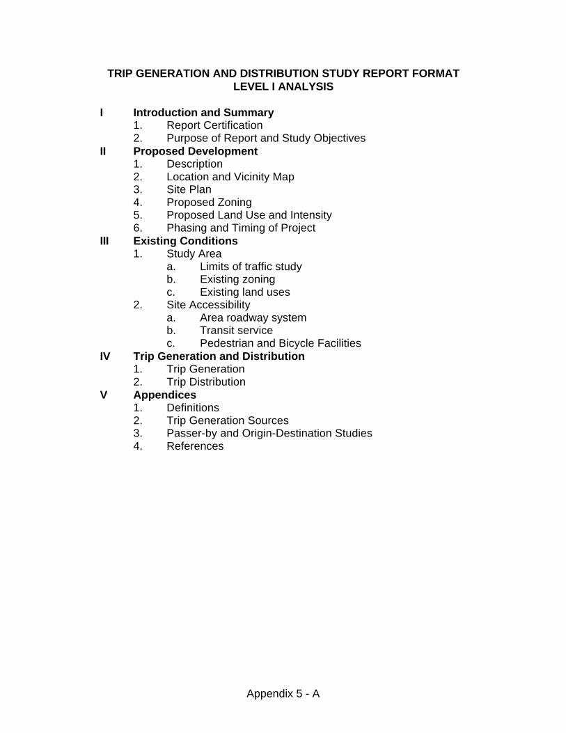
Appendix 5 - A
TRIP GENERATION AND DISTRIBUTION STUDY REPORT FORMATLEVEL I ANALYSIS
I Introduction and Summary1. Report Certification2. Purpose of Report and Study Objectives
II Proposed Development1. Description2. Location and Vicinity Map3. Site Plan4. Proposed Zoning5. Proposed Land Use and Intensity6. Phasing and Timing of Project
III Existing Conditions1. Study Area
a. Limits of traffic studyb. Existing zoningc. Existing land uses
2. Site Accessibilitya. Area roadway systemb. Transit servicec. Pedestrian and Bicycle Facilities
IV Trip Generation and Distribution1. Trip Generation2. Trip Distribution
V Appendices1. Definitions2. Trip Generation Sources3. Passer-by and Origin-Destination Studies4. References
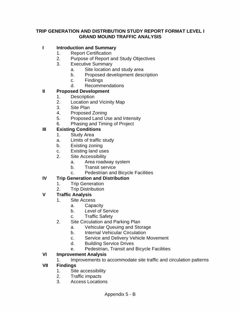
Appendix 5 - B
TRIP GENERATION AND DISTRIBUTION STUDY REPORT FORMAT LEVEL IGRAND MOUND TRAFFIC ANALYSIS
I Introduction and Summary1. Report Certification2. Purpose of Report and Study Objectives3. Executive Summary
a. Site location and study areab. Proposed development descriptionc. Findingsd. Recommendations
II Proposed Development1. Description2. Location and Vicinity Map3. Site Plan4. Proposed Zoning5. Proposed Land Use and Intensity6. Phasing and Timing of Project
III Existing Conditions1. Study Areaa. Limits of traffic studyb. Existing zoningc. Existing land uses2. Site Accessibility
a. Area roadway systemb. Transit servicec. Pedestrian and Bicycle Facilities
IV Trip Generation and Distribution1. Trip Generation2. Trip Distribution
V Traffic Analysis1. Site Access
a. Capacityb. Level of Servicec. Traffic Safety
2. Site Circulation and Parking Plana. Vehicular Queuing and Storageb. Internal Vehicular Circulationc. Service and Delivery Vehicle Movementd. Building Service Drivese. Pedestrian, Transit and Bicycle Facilities
VI Improvement Analysis1. Improvements to accommodate site traffic and circulation patterns
VII Findings1. Site accessibility2. Traffic impacts3. Access Locations
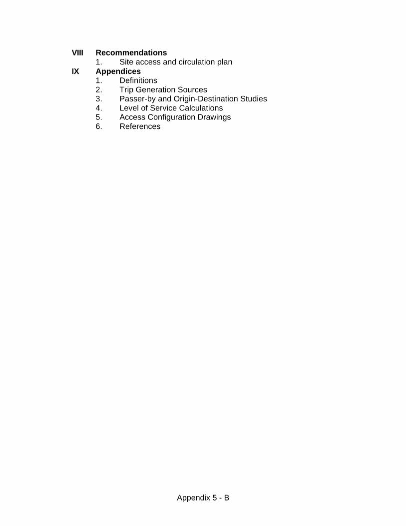
Appendix 5 - B
VIII Recommendations1. Site access and circulation plan
IX Appendices1. Definitions2. Trip Generation Sources3. Passer-by and Origin-Destination Studies4. Level of Service Calculations5. Access Configuration Drawings6. References
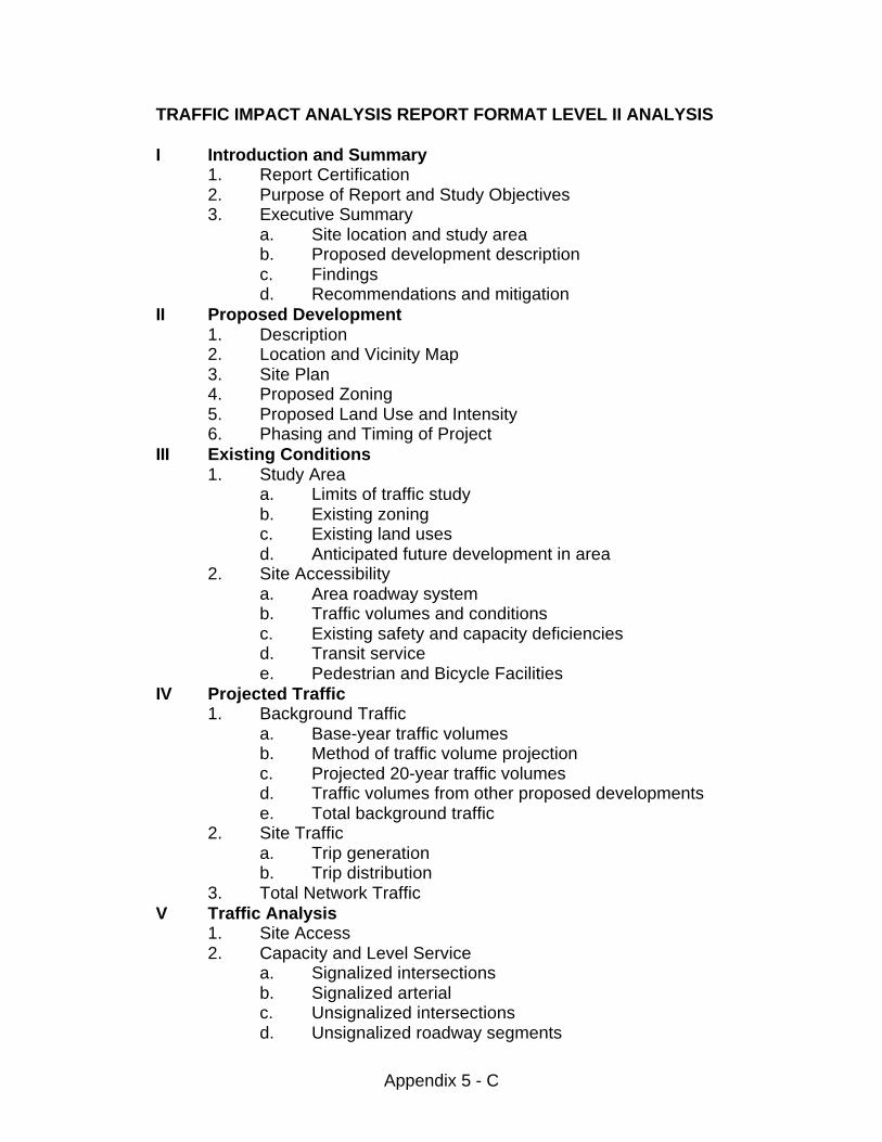
Appendix 5 - C
TRAFFIC IMPACT ANALYSIS REPORT FORMAT LEVEL II ANALYSIS
I Introduction and Summary1. Report Certification2. Purpose of Report and Study Objectives3. Executive Summary
a. Site location and study areab. Proposed development descriptionc. Findingsd. Recommendations and mitigation
II Proposed Development1. Description2. Location and Vicinity Map3. Site Plan4. Proposed Zoning5. Proposed Land Use and Intensity6. Phasing and Timing of Project
III Existing Conditions1. Study Area
a. Limits of traffic studyb. Existing zoningc. Existing land usesd. Anticipated future development in area
2. Site Accessibilitya. Area roadway systemb. Traffic volumes and conditionsc. Existing safety and capacity deficienciesd. Transit servicee. Pedestrian and Bicycle Facilities
IV Projected Traffic1. Background Traffic
a. Base-year traffic volumesb. Method of traffic volume projectionc. Projected 20-year traffic volumesd. Traffic volumes from other proposed developmentse. Total background traffic
2. Site Traffica. Trip generationb. Trip distribution
3. Total Network TrafficV Traffic Analysis
1. Site Access2. Capacity and Level Service
a. Signalized intersectionsb. Signalized arterialc. Unsignalized intersectionsd. Unsignalized roadway segments
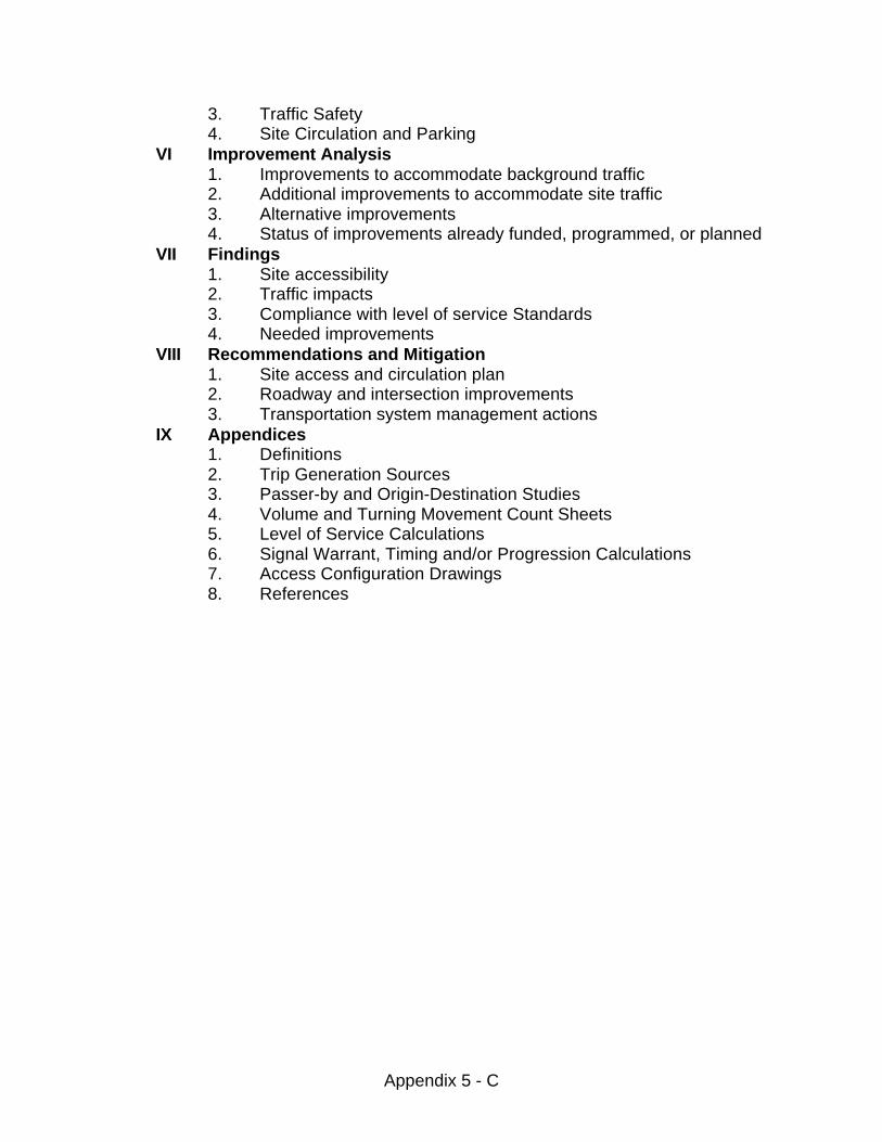
Appendix 5 - C
3. Traffic Safety4. Site Circulation and Parking
VI Improvement Analysis1. Improvements to accommodate background traffic2. Additional improvements to accommodate site traffic3. Alternative improvements4. Status of improvements already funded, programmed, or planned
VII Findings1. Site accessibility2. Traffic impacts3. Compliance with level of service Standards4. Needed improvements
VIII Recommendations and Mitigation1. Site access and circulation plan2. Roadway and intersection improvements3. Transportation system management actions
IX Appendices1. Definitions2. Trip Generation Sources3. Passer-by and Origin-Destination Studies4. Volume and Turning Movement Count Sheets5. Level of Service Calculations6. Signal Warrant, Timing and/or Progression Calculations7. Access Configuration Drawings8. References
6-1
CHAPTER 6ROADWAY BASES, SURFACING AND RESTORATION
6.00 ROADWAY BASES, SURFACING AND RESTORATION
6.01 Surfacing Requirements6.02 Restoration
Appendix 6 - A Private Roadway SectionAppendix 6 - B Minor Local Roadway SectionAppendix 6 - C Local Roadway SectionAppendix 6 - D Collector Roadway SectionAppendix 6 - E Arterial Roadway SectionAppendix 6 - F Clear Zone/Recovery AreaAppendix 6 - G Cul-de-Sac, Hammerhead DetailAppendix 6 - H Utility Trench Detail
6-2
6.00 ROADWAY BASES, SURFACING AND RESTORATION
6.01 Surfacing Requirements
A. Design
A pavement surfacing design procedure shall be performed for all Countyroads. The design life for all roads shall be 20 years with a growth factorof 5% . The design procedure used shall be approved by the Engineerand consider the following:
1. Traffic Loading - An estimate of the number and types of loadingsthe roadway will carry for the design life. This estimate of loadingshall be established by a procedure accepted by the Engineer andbe expressed in 18-Kip Equivalent Single Axle Loads (ESALs).
2. Subgrade Support - A representative value for the stiffness of thenative material on which the road will be built. This value shall beestablished by a procedure accepted by the Engineer and beexpressed as resilient modulus.
3. Analysis - a procedure for establishing the surfacing depthrequirements for a given traffic loading and subgrade resilientmodulus. This procedure shall be approved by the Engineer. Thefollowing procedure is pre-approved:
Guide for the Design of Pavement Structures 1993 by theAmerican Association of State Highway and TransportationOfficials.
B. Minimum Thickness:
Regardless of the thickness computed by the design procedure, theminimum thickness of in-place compacted surfacing on a road shall be asfollows:
Local:0.20' Asphalt Concrete Pavement (when required)0.17' Crushed Surfacing Top Course0.75' Gravel Base
Collector & Arterial:0.25' Asphalt Concrete Pavement0.17' Crushed Surfacing Top Course0.75' Gravel Base
6-3
C. All plan submittals shall be accompanied by the soils and traffic analysison which the design was based. All minimum surfacing requirementsassume an acceptable, well drained, stable, compacted subgrade. Additional measures may be required at the Engineer’s discretion ifevidence exists of unstable subgrade.
D. Rural roads with a traffic volume less than 200 ADT may be paved bymeans of a light bituminous surface treatment (LBST). The LBST shallconsist of no less than two applications of oil. The gravel thickness shallbe designed according to good engineering practices considering thequality of the underlying soil. The design method shall be subject toapproval by the Engineer. In no case shall the gravel thickness be lessthan eleven inches, two inches of crushed surfacing top course and nineinches of gravel base. The developer shall provide funding for anadditional application of oil to be placed as a seal coat approximately oneyear after initial construction.
6.02 Restoration
The intent of this section is to insure the life expectancy, structural integrity andoverall safety of the public right-of-way as related to any encroachment into theroad right-of-way. This section pertains to existing public roads and those roadsproposed to be dedicated to the County as public roads.
A. All roadway crossings shall be done by means of boring or pushing(untrenched installation). Opening of the roadway surface shall not bepermitted unless it has been determined by the Engineer, or hisdesignated representative, that boring or pushing can not be done.
B. When a trenched crossing is approved, restoration shall be in accordancewith one of the following guidelines:
1. Controlled density backfill, CDF shall be required as a backfillmaterial; or
2. Select backfill, meeting the requirements of the StandardSpecifications may be used. Backfill shall be compacted to at least95 percent density and placed in a maximum of 12-inch lifts, asspecified in the Standard Specifications. Written verification ofcompaction, based upon acceptable testing methods, andplacement of the backfill shall be required.
C. Native material may be used as backfill material when standardacceptable tests show the material meets the requirements for backfillmaterial as specified in the Standard Specifications. The requirements forcompaction and placement in item B above also apply when nativematerial is used.
6-4
D. All utilities placed parallel to and within the pavement structure shall berequired to rebuild a minimum of half the road, from centerline for utilitiesin one driving lane, to include grinding and the replacement of a minimum0.20' of asphalt.
E. When conditions are warranted, the Engineer may require all or a portionof the trench be backfilled with a combination of select backfill or CDF. Conditions that may warrant a combination use may be, but not limited to,the depth of trench required, the type of material that is being excavatedand crossings on arterial and collector roadways.
F. When conditions are warranted, the Engineer may require financialsecurity for a minimum of 10-years in the form of a bond, irrevocable letterof credit or irrevocable assignment of interest in a bank account for all or aportion of restoration. Conditions that may warrant this may be, but notlimited to, the placement of utilities in or near sensitive areas and areas ofcontinuous settlement.
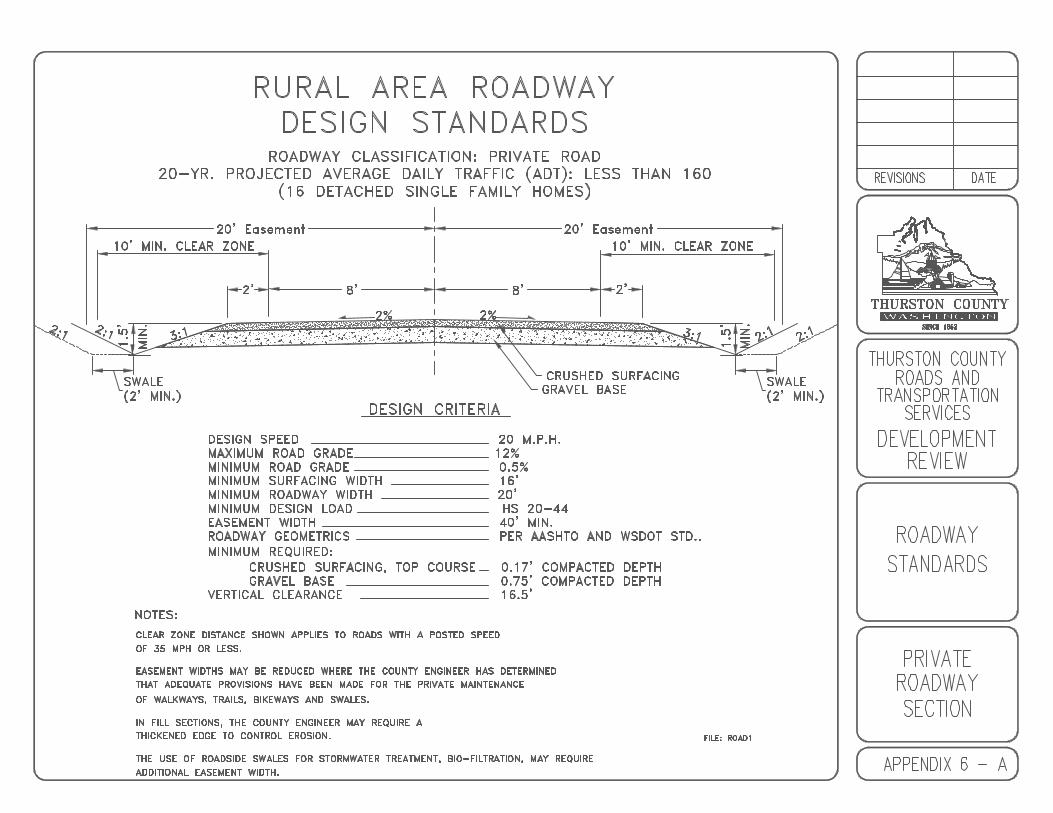
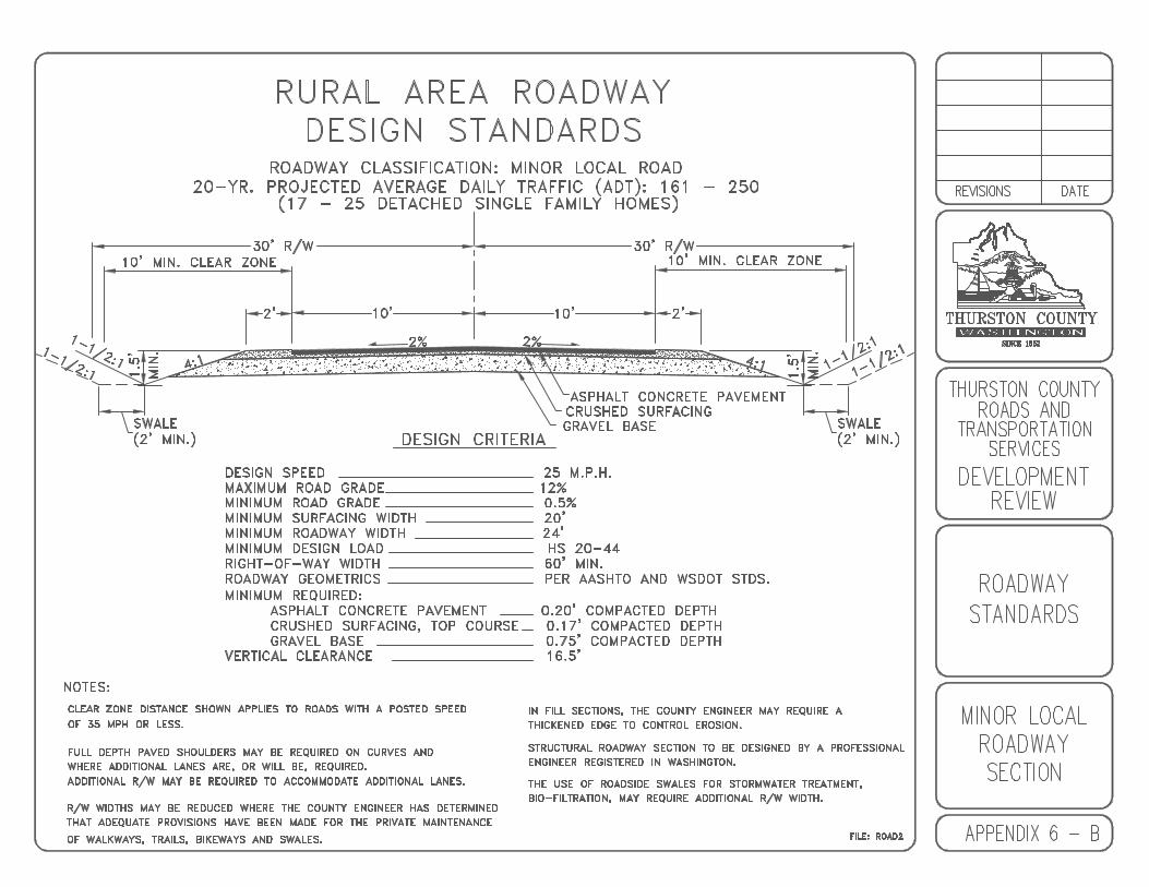
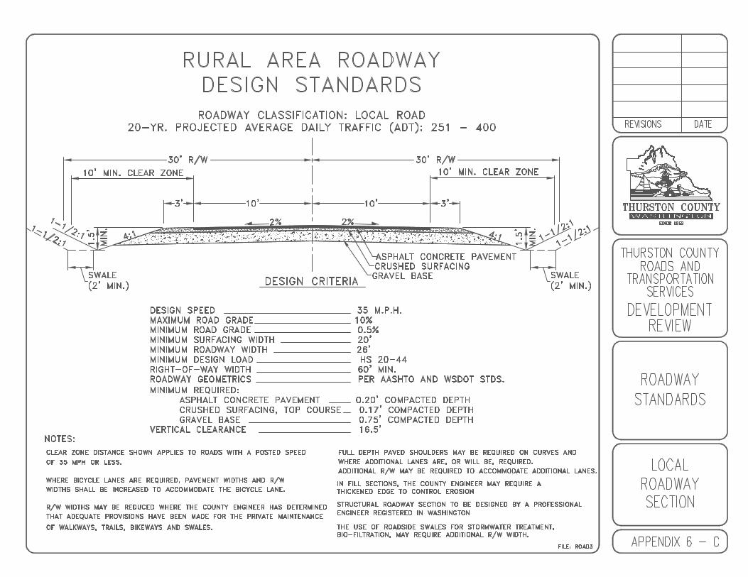

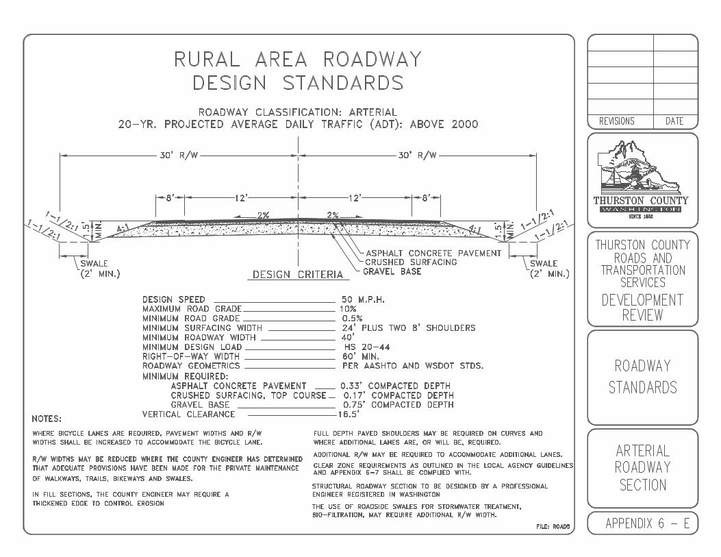
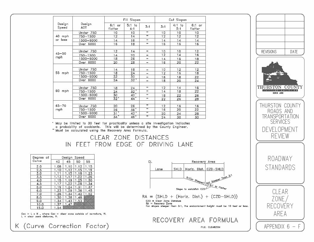
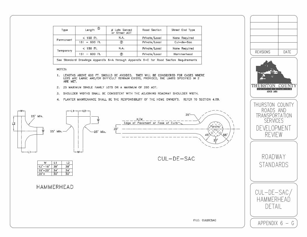
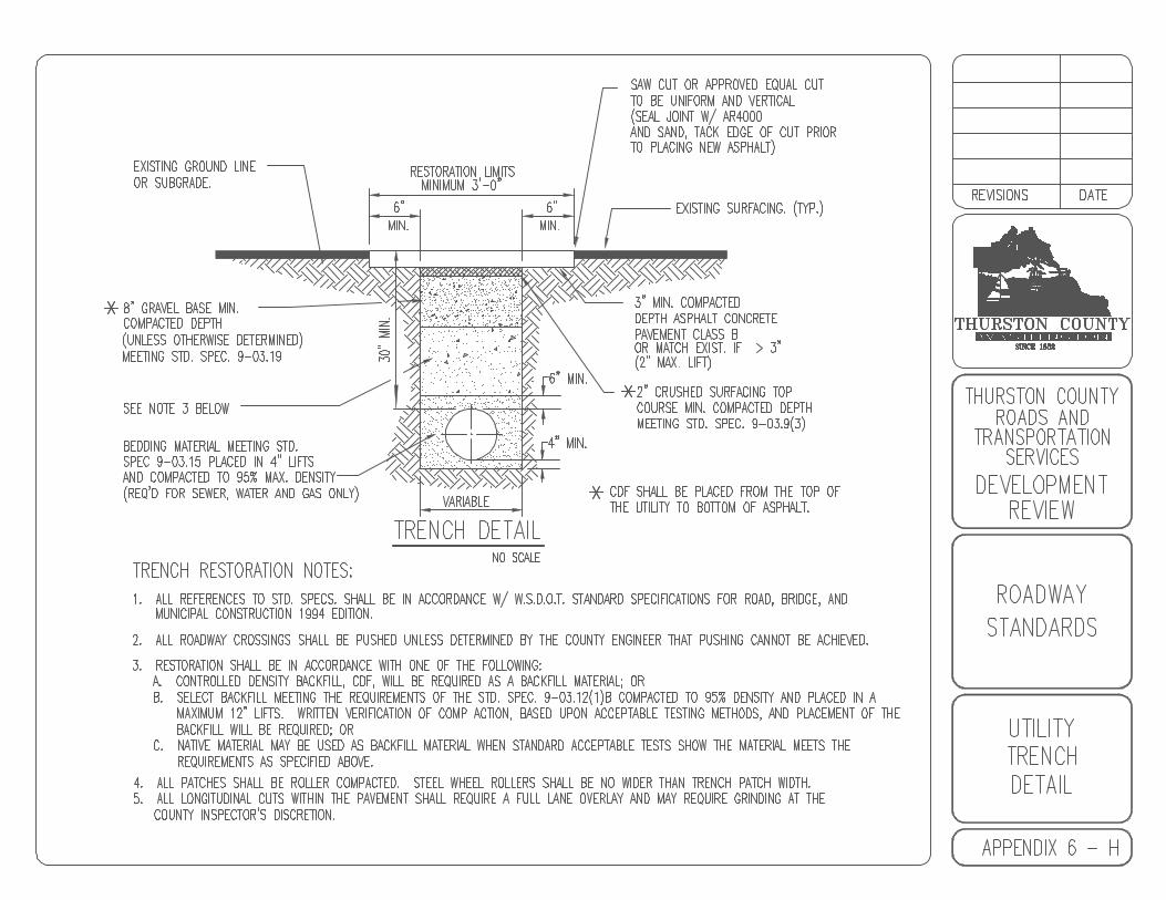
7-1
CHAPTER 7ACCESS
7.00 ACCESS
7.01 General7.02 Sight Distance7.03 Location of Access Points7.04 Construction of Access Points7.05 Horizontal Alignment of Access Points7.06 Vertical Alignment of Access Points7.07 Left Turn, Acceleration and Deceleration Lanes7.08 Intersections
Appendix 7 - A County Road AccessesAppendix 7 - B Access Point Grades

7-2
7.00 ACCESS
7.01 General
A. Access to State Highways is regulated by the Washington StateDepartment of Transportation. The property owner desiring accessto a State Highway is responsible to coordinate with WSDOT forsatisfactory completion of any requirements prior to construction.
B. An Encroachment Permit shall be obtained through theDevelopment Services Department prior to accessing Countyroads. Construction of access points or related improvements shallnot be allowed without a valid Encroachment Permit. Applicationfor Encroachment Permits shall be evaluated and EncroachmentPermits issued based on the ability of the proposed access or useto meet these Standards.
Access widths and locations for driveways are determined atthe time of acquisition of the Encroachment Permit. As a rule,access widths are:
1. Residential minimum width 20 feet plus beveled ends. 2. Commercial minimum width 35 feet plus beveled ends.
C. Access points for parking and loading areas shall be designed sothat backing maneuvers from or onto a public road right-of-way willnot occur. All vehicles shall exit the property in a forward motion. This does not apply to single family or duplex residential uses onnon-collector or non-arterial roads.
D. Where necessary for the safe and efficient movement of traffic, theEngineer may require an investigation by the applicant to determinewhether access points should be designed to limit turningmovements. The Engineer may also require joint access andcirculation agreements between neighboring properties to furtherprovide safe and efficient movement of traffic.
E. Temporary access may be granted to undeveloped property prior tocompletion of a final development plan if access is needed forconstruction of preliminary site access. Temporary access pointsshall meet the requirements of these Standards. They are subjectto removal, relocation, or redesign after development planapproval.
F. Secondary access for emergency vehicles may be required forcertain high volume or public safety sensitive developments. They
7-3
shall be designed to the satisfaction of the Engineer based onreview by the Thurston County Fire Marshal.
G. No relocation, alteration or reconstruction of existing access pointsshall be permitted without prior written approval from the Engineer.
H. All abandoned driveway areas on the same frontage shall be removedand the curbing and sidewalk, or shoulders and ditch section, shall beproperly restored in accordance with these Standards.
7.02 Sight Distance
All access points shall conform with the minimum requirements in Section 4.04.
7.03 Location of Access Points
A. The spacing of access points and their separation fromintersections is critical to maintaining access point and roadwaytraffic flow. Thoughtful spacing of access points can reducevehicular and pedestrian conflicts while helping to avoid trafficaccidents. As a general rule, access points shall be a minimum of130 feet from an intersection, measured from the property cornernearest the intersection.
The following guidelines shall be followed for accessing aCounty road:
1. Arterial Roads
Internal collection of traffic shall be required. Access points shall belimited to one access point per 500 feet of frontage, taking into accountaccesses on both sides of the road and adjoining property. Lots within asubdivision shall be designed so that lots adjacent to an arterial road arenot allowed direct access.
2. Collector Roads
Internal collection of traffic shall be required. Access points shall belimited to one access point per 300 feet of frontage, taking into accountaccesses on both sides of the road and adjoining property. Lots within asubdivision shall be designed so that lots adjacent to an arterial road arenot allowed direct access.
3. Local Roads
Internal collection of traffic is desirable. Access points are not limited forlocal roadways.
7-4
B. Where a property has frontage on more than one roadway, accessshall be limited to the lowest volume roadway where the impacts ofthe new access are minimized. Access onto other higher volumeroads shall be denied in the interest of traffic safety or in order tolessen congestion on the higher volume road.
C. Access points for commercial or industrial property uses shall beplaced directly opposite each other wherever possible. If this is notpossible, a separation between the nearest edges of such oppositeaccess points shall be as close to the spacings as listed in Section7.04 A. When such spacing cannot be attained, the Engineer mayrequire investigation to substantiate whether or not left turns shouldbe prohibited into or out of the access points.
D. Access to commercial or industrial use corner lots shall be locatedon the lower volume roadway and as close as practicable to theproperty line most distant from the intersection. Right in and rightout conditions may also be required by the County.
E. No portion of an access shall be permitted within curb returns.
F. The nearest edge of any access point flare or radius shall be atleast 3 feet from the nearest point of a fire hydrant, no parkingzone, utility pole, traffic signal installation or light standard, mailboxcluster or other similar appurtenance.
7.04 Construction of Access Points
A. All access points on arterial and collector roadways shall beinstalled prior to final project/plat approval. Access points onarterial and collector roadways serving two or more parcels shall berequired to construct a paved apron as shown in Appendix 7-A.
B. The construction of all access points involving removal of existingvertical curb or vertical curb and gutter shall conform to this section.
C. When cutting through or crossing vertical curbs, gutters andsidewalks, access approaches shall extend from the curb to backof sidewalk and shall be portland cement concrete. The cross slopeshall not exceed 2%.
D. When an opening for an access or for any other purpose is to beconstructed through an existing portland cement concrete verticalcurb, the existing curb, or curb and gutter shall be saw cut at thelimits of work or removed to the nearest construction joint and theopening replaced with standard curb and driveway. The cross slopeshall not exceed 2%.
7-5
E. Existing road trees, road lights, traffic signal facilities, utility poles,and fire hydrants shall be shown on any plan for access pointconstruction in an area of existing vertical curb.
F. Prior to commencing any necessary removal or relocation of anypublic utilities, structures, trees, or plantings due to construction ofan access point, the applicant/developer shall secure approval fromthe person or persons having ownership or control of such facilitiesor features.
G. All constructed access points to a County road shall be inspected by theCounty. If said access point, including culvert, is not installed inaccordance with these Standards, it shall be removed and reinstalled bythe applicant to the satisfaction of the County. A fee shall be charged foreach additional inspection. If the applicant does not remove and reinstallthe access and culvert within thirty days from the date of notice, theCounty has the right to remove said access and culvert at applicant’sexpense. Upon removal by the County, the Encroachment Permit shall bevoid and the applicant shall resubmit an application for a new access.
7.05 Horizontal Alignment of Access Points
All access points shall be angled a minimum of 75 degrees to the road, 90degrees preferred, unless designated right turn only, in which case the angleshall be at least 45 degrees and then only with the Engineer's approval. Refer toAppendix 7-A, County Road Accesses.
EXCEPTION: Access points designed for large vehicles, WB-40 and greater,shall be angled a minimum of 85 degrees to the road.
7.06 Vertical Alignment of Access Points
A. Approach grades and configuration shall accommodate future roadwidening to prevent major access point reconstruction.
B. For maximum access grades, refer to Appendix 7-B, Access PointGrades.
7.07 Left Turn, Acceleration and Deceleration Lanes
The need for left turn, acceleration and deceleration lanes in conjunction withdevelopment proposals shall be determined based on the criteria in AASHTOand the WSDOT Design Manual. Evaluation by the Engineer may requiresubmittal of traffic data by the Applicant/Developer.
7.08 Intersections
Refer to Section 4.09
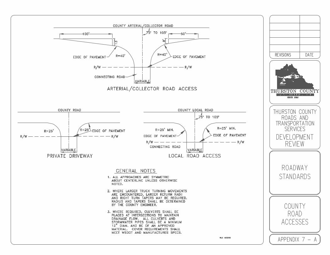
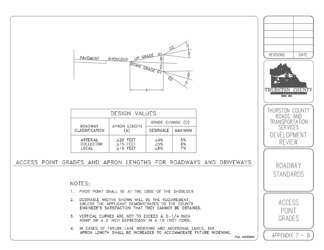
8-1
CHAPTER 8ROADSIDE FEATURES
8.00 ROADSIDE FEATURES
8.01 Side Slopes8.02 Survey Monuments8.03 Mailboxes8.04 Landscaping8.05 Road Illumination8.06 Roadway Barricades8.07 Bollards8.08 Guardrail8.09 Off-Road Parking Spaces8.10 Road Name Signs8.11 Stop Signs8.12 Roadway Striping, Buttoning, and Delineation
Appendix 8 - A Survey Monument StandardAppendix 8 - B Community Mail Box
8-2
8.00 ROADSIDE FEATURES
8.01 Side Slopes
Side slopes shall be stabilized by grass sod or seeding, or by other planting orsurfacing material acceptable to the Engineer.
8.02 Survey Monuments
Refer to Appendix 8-A for Survey Monument Standard
A. Reference
All surveyed monuments horizontal or vertical tied, placed, replaced orcalculated shall be coordinated (X,Y,Z) to the Thurston County HighPrecision Network (TCHPN).
B. Placement
Survey control monuments, including existing monuments disturbed,destroyed or removed during construction, shall be placed or replaced bya registered surveyor at the expense of the applicant in accordance withrecognized good practice of land surveying, and in conformance with allapplicable state law, rules and local regulations.
C. Records
A legal survey conforming to Chapter 58.09 RCW shall be filed with theCounty Auditor and the Engineer showing methods used to establish themonument's position with references tying the monument's location. Formal recorded documents, containing the registered surveyor'scertification, monumentation, and staking, shall be placed by theregistered surveyor in accordance with Chapter 58.09 RCW.
D. Plat Surveys
Survey monuments shall be placed at all exterior boundary corners ofplats. A signed and sealed statement from a registered surveyor that allmonuments and corners indicated on the subdivision plat have been setand are in good condition shall be required prior to final plat approval.
E. Road Surveys
Survey monuments, Appendix 8-A, shall be placed in County roads at:
1. Points of curvature2. Points of tangent

8-3
3. Intersections 4. Centers of cul-de-sacs5. As needed for intervisibility6. As required by the County
If a PI falls within the paved roadway surface, a PI monument may replace thecorresponding PC and PT monuments. Monuments shall not be placed inlandscape medians. Witness monuments shall be offset in the roadway and sodescribed.
8.03 Mailboxes
Mailboxes shall be set in accordance with the LAG manual, and as follows:
A. U.S. Postal Service approval shall be required.
B. Mailbox supports shall be of breakaway design.
C. Mailbox clusters shall conform to WSDOT Standard Plan H-12.
D. Community mailboxes shall not be allowed within the County right-of-waywith the exception of the Grand Mound Urban Growth Area. Within theGrand Mound Urban Growth Area, community mailboxes as shown inAppendix 8-B may be used with approval from the County. When used,they shall be clearly shown on the plan sheets.
8.04 Landscaping
A. All landscaping within County right-of-way shall require approval of theEngineer.
B. Landscaping shall be of the type and placement to achieve and maintainthe sight distance requirements in Section 4.04.
C. No landscaping shall be allowed within a drainage ditch or drainageswales.
D. Installation and maintenance of all landscaping shall be the responsibilityof the applicant or the homeowner’s association.
8.05 Road Illumination
A. Road illumination may be required at school bus stops as identified by thelocal school district.
B. Road illumination shall be installed at critical intersections as required bythe County.

8-4
C. Installation, maintenance, and operation billing shall be the responsibilityof the applicant or the homeowner’s association.
8.06 Roadway Barricades
Refer to WSDOT Standard Plans.
8.07 Bollards
A. Acceptable Uses
When necessary to deny motor vehicle access to an easement, tract, ortrail, except for maintenance or emergency vehicles, the point of accessshall be closed by a line of bollards.
B. Placement
One or more fixed bollards shall be placed on each side of the traveledway and removable, locking bollards shall be placed across the traveledway and outside of the roadway clear zone. Spacing shall provide onebollard on centerline of trail and other bollards spaced at intervals notexceed 50 inches on centers.
C. Fire Access
No fire apparatus access roads shall be blocked in this manner withoutthe approval of the County Fire Marshal and local Fire District Chief.
8.08 Guardrail
All roads that do not meet the minimum roadway clear zone and recovery areacriteria, to include slopes, shall be required to install guardrail. An exception tothis is when the installation of guardrail creates a greater hazard with thepotential of redirecting errant vehicles into oncoming traffic.
Guardrail installations shall conform to WSDOT Standard Plans, WSDOT DesignManual and LAG Manual.
8.09 Off-Road Parking Spaces
Off-road parking shall not be allowed in County right-of-way, unless approved bythe Engineer.
When off-road parking is approved, the design shall take into account theminimum required Standards and the requirements of Title 12 and Title 20 of theThurston County Code.
8-5
8.10 Road Name Signs
A. Required for all public and private roads providing access to 5 or morelegal lots.
B. Road name signs shall be installed in accordance with WSDOTStandards.
C. Placement of private road name signs in County right-of-way shall requirea County encroachment permit and be installed by County forces atapplicant’s expense.
D. Any sign constructed in County right-of-way in non-conformance to theseStandards may be removed by County forces and any liability incurred bythe County due to non-conformance by the applicant shall be transferredto the applicant.
E. Road naming shall comply with Chapter 13.44 of the Thurston CountyCode. Contact Development Services to coordinate road names.
8.11 Stop Signs
Stop signs shall be installed in accordance with the MUTCD.
8.12 Roadway Striping, Buttoning, and Delineation
A. When required by the County, roadway striping, buttoning or other trafficdelineators shall be installed in accordance with the approved plans, theMUTCD and the County traffic division.
B. Before any pavement marking work takes place, the applicant shallcontact the County traffic division. An on-site meeting may be required toreview the work and method of construction.
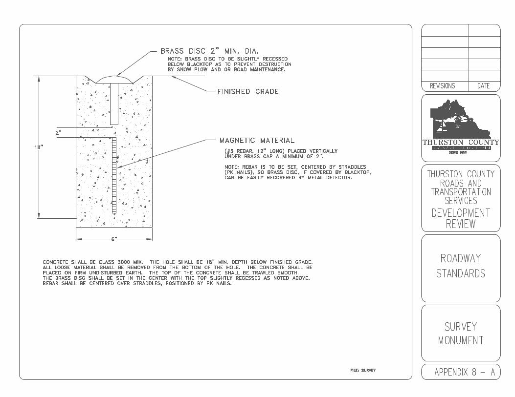
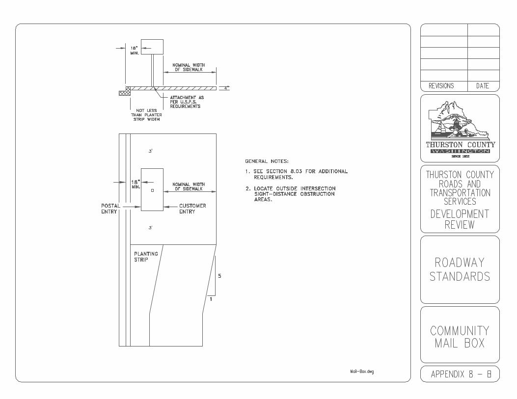
9-1
CHAPTER 9RETAINING WALLS
9.00 RETAINING WALLS
9.01 Design Criteria9.02 Rock Retaining Walls
Appendix 9 - A Rock Retaining Wall
9-2
9.00 RETAINING WALLS
9.01 Design Criteria
A. Retaining walls on public or private roads shall be designed andconstructed to meet the minimum requirements of the AASHTO BridgeSpecifications.
B. Retaining walls with a height of four feet or greater shall be designed,signed, and stamped by a registered engineer licensed in the State ofWashington, and shall be submitted by the applicant for approval by theEngineer.
C. Refer to Appendix 9-A.
9.02 Rock Retaining Walls
A. Rock retaining walls, not exceeding the maximum height specified inAppendix 9-A, may be used for the containment of cut slopes or fillembankments in stable soil conditions which will result in no significantfoundation settlement or outward thrust upon the walls.
For heights over 4 feet or when soil is unstable, a structural wall ofacceptable design shall be used and calculations shall be submitted to theCounty for approval. A soils investigation and report by a geotechnicalEngineer may be required by the County if soils conditions arequestionable.
B. Materials:
1. Rock sizes shall be as shown in Appendix 9-A.
2. The rock material shall be as nearly rectangular as possible. Nostone shall be used which does not extend through the wall. Therock material shall be hard, sound, durable and free fromweathered portions, seams, cracks and other defects. The rockdensity shall be a minimum of 160 pounds per cubic foot.
C. The retaining wall shall be started by excavating a trench, not less than 12inches in depth below subgrade in excavation sections or below theexisting ground level in embankment sections.
D. Rock selection and placement shall be such that there will be minimumvoids and, in the exposed face of the wall, no open voids over 6 inchesacross in any direction. The final course shall have a continuousappearance and be placed to minimize erosion of the backfill material. The larger rocks shall be placed at the base of the rockery so that the wall
9-3
will be stable and have a stable appearance. The rocks shall be placed ina manner such that the longitudinal axis of the rock shall be at right anglesor perpendicular to the rockery face. The rocks shall have all incliningfaces sloping to the back of the rockery. Each course of rocks shall beseated as tightly and evenly as possible on the course beneath.
E. The wall backfill shall consist of gravel backfill for walls as per theStandard Specifications. This material shall be placed to a 12-inchminimum thickness between the entire wall and the cut or fill material. The backfill material shall be placed in lifts to an elevation approximately 6inches below the top of each course of rocks as they are placed, until theuppermost course is placed. Any backfill material on the bearing surfaceof a rock course shall be removed before setting the next course.
F. A 6-inch, minimum inside diameter, perforated drain pipe shall be installedbehind the first course of rock and laid on original ground. The perforateddrain pipe shall be surrounded by gravel backfill for drains as shown inAppendix 9-A. Positive drainage for the perforated drain pipe shall beprovided and shown on the construction plan.
G. The face of the rockery shall be sloped at 1/4 to 1 or flatter.
H. For rock walls in fill sections all fill material placed beyond the backfill shallbe placed and compacted in a maximum of 6-inch compacted lifts.
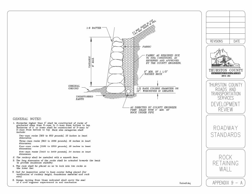
10-1
CHAPTER 10BRIDGES
10.00 BRIDGES
10.01 Principle References10.02 Bridge Geometrics10.03 Bridge Design Criteria10.04 Special Permits10.05 Existing Bridges
10-2
10.00 BRIDGES
10.01 Principal References
Except as specified below, Thurston County bridges, whether on publicroads or on private roads serving subdivided land, shall be designedand constructed to meet the minimum requirements set forth in thelatest edition, including all interim addenda, of the AASHTO BridgeSpecifications. Bridge and approach railings shall be provided inaccordance with that reference or with AASHTO “Guide for Selecting,Locating, and Designing Traffic Barriers.” All new bridges shall bedesigned to carry an AASHTO HS 20-44 live load or greater.
10.02 Bridge Geometrics
A. In the general case, the bridge roadway shall comprise the fullwidth and configuration of the road being served -- traveledway plus curb, sidewalks, walkway, bike lane, equestrian lane,and/or shoulder on both sides. Requirements of utilities shallbe duly considered. Bridge roadway width shall be measuredbetween curbs or between faces of rails, whichever is less, butin no case shall be less than 28 feet. Bridges to be dedicated tothe County for public use shall be constructed of concreteunless approved otherwise by the Engineer.
B. Where typical speed is 35 MPH or higher and significant pedestrian, bikeand/or horseback traffic can be expected, the Engineer may require thatthe lanes for these other modes of traffic be separated from motor vehicletraffic by use of a bridge traffic trail and further protected by a rail at outeredge. See WSDOT Design Manual.
C. Approach railings shall be made structurally continuous with bridgerailings and shall meet AASHTO specifications as cited in Section 10.01above.
D. Overhead vertical clearances for motor traffic on the traveled roadway orunder overpasses shall be 16.5 feet minimum. Vertical clearance ofstructures above a walkway or sidewalk shall be eight feet minimum.
10.03 Bridge Design Criteria
A. Approach slabs shall be required for all bridges. New bridge plans shallprovide pavement seats for approach slabs unless otherwise approved bythe Engineer. Waiver of the requirement for approach slabs may beconsidered only on the basis of adequate geotechnical analysis. Approach slabs shall be constructed in accordance with the StandardPlans A-2.
10-3
B. New bridge decks and approach slabs shall be designed with a protectivesystem to prevent corrosion of the reinforcing steel.
C. Criteria under other recognized road bridge project classifications, such asthose of 3-R projects, set forth in the LAG Manual, may be applied underconditions deemed appropriate by the Engineer.
10.04 Special Permits
Permit requirements for construction or reconstruction of bridges include but arenot limited to the following:
A. Bridges over navigable waters require U.S. Coast Guard permits.
B. Bridges involving deposition of material in waters of the United States ortheir adjacent wetlands require a U.S. Army Corps of Engineers Permit.
C. Any work involving alteration of flow or bed materials below the ordinaryhigh water line of any water body or water course requires a HydraulicProject approval from the State Department of Fish and Wildlife.
D. Any project requiring a U.S. Army Corps of Engineers Permit also requiresa Water Quality Certification from the State Department of Ecology.
E. Bridges across streams in State Flood Control Zones require a permitfrom the State Department of Ecology.
F. Where Bridge structures lie on or over submerged lands, a lease from theWashington State Department of Natural Resources may be necessary.
G. Structures located on shoreline zones as defined in the Thurston CountyShoreline Master Program require a substantial development permit fromthe Thurston County Development Services Department, subject toconcurrence of the State Department of Ecology.
H. Bridges over waterways shall be submitted, stamped and sealed by alicensed civil engineer. Bridges require the Engineer’s approval of thesize and shape of the hydraulic opening, the height of the superstructureover high water, the location of piers, channel improvement, and otherhydraulic considerations.
10.05 Existing Bridges

10-4
Existing bridges shall meet all of the specific requirements in these Standards. Written certification by a Structural Engineer licensed in the State of Washingtonspecifically outlining compliance with each of the requirements in theseStandards shall be required prior to acceptance by the County.

11-1
CHAPTER 11DRAINAGE
11.00 DRAINAGE
11.01 Catch Basins, Manholes and Inlets
11-2
11.00 DRAINAGE
All project submittals shall be in compliance with the Drainage and ErosionControl Manual for Thurston County. In addition, drainage facilities within currentor future County Right-of-Way must be of the type and nature that can be easilymaintained by County forces. This typically includes as a minimum, 10 inchdiameter storm sewer pipe, standard catch basins and manholes and roadsideditches and swales of a minimum depth of 18 inches. All other facilities, such asfrench drains, curtain drains, drywells and stormwater ponds shall be installedoutside County Right-of-Way and be maintained by the applicant orhomeowner’s association.
Stormwater facilities shall also be designed to accommodate the stormwaterfrom the addition of frontage improvements, including tributary area.
Projects requiring an agreement for the operation and maintenance of thestormwater facilities shall be required to provide the County with a ProjectEngineer's Certification of the facilities prior to release of the financial security. The financial security shall not be released until all facilities are completed andrepaired as per the approved plans.
11.01 Catch Basins, Manholes and Inlets
A. Maximum spacing on surface drainage courses between inlets or catchbasins shall be 150 feet on road grades less than 1.0% and 200 feet ongrades from 1.0% to 3.0%. When the road grade is 3.0% or greater, themaximum spacing shall be 300 feet. Additional catch basins shall beinstalled as needed to confine drainage to the gutter and prevent roaddrainage from sheet flowing across roadways or intersections.
B. Maximum spacing on main storm sewers between access structures,whether catch basins or manholes, shall be 300 feet.
C. On storm sewers with depths less than five feet to invert of lowest pipe,catch basins may be either Catch Basin Type 1, Catch Basin Type 1-L orCatch Basin Type 2.

12-1
CHAPTER 12UTILITIES
12.00 UTILITIES
Refer to Accommodation of Utilities on Thurston County Rights-of-Way, Chapter 13.56 Thurston County Code.
13-1
CHAPTER 13CONSTRUCTION CONTROL AND INSPECTION
13.00 CONSTRUCTION CONTROL AND INSPECTION
13.01 Basis for Control of Work13.02 Engineer Certification13.03 Inspection Criteria13.04 Notification Requirements13.05 Revisions to Inspection Sequence13.06 Required Inspections to be Performed by the Applicant13.07 Materials Sampling and Testing
13-2
13.00 CONSTRUCTION CONTROL AND INSPECTION
13.01 Basis For Control of Work
A. Work performed within the County rights-of-way, or as described inthese Standards, whether by or for a private applicant, or by aCounty contractor, shall be done to the satisfaction of the Countyand in accordance with the approved plans and specifications andthese Standards. Unless otherwise approved, any revision to plansshall be approved by the County before being implemented.
B. The County shall have the authority to enforce these Standards aswell as other referenced or pertinent specifications. The Countymay appoint project assistants and inspectors as necessary toinspect the work on public and private roadways. They shallexercise such authority as the Engineer may delegate. On all otherprojects, the Project Engineer shall be responsible for allinspections as outlined in this chapter.
C. It is the responsibility of the applicant, contractor and their agentsto have an approved set of plans and permits on the job sitewherever work is being accomplished. If requested by the County,the applicant shall be required to provide tests to substantiate theadequacy and/or placement of construction materials.
D. It is the responsibility of the applicant, contractor, or their agents tonotify the County in advance of the commencement of any work onsignificant projects.
E. Failure to comply with the provisions of these Standards may resultin stop work orders, removal of work accomplished, or otherpenalties as established by law.
F. Prior to commencing work on the project, the sponsor shall prepare andsubmit a signing plan to the Engineer for review and approval. From timeto time, as progress of the work indicates, as conditions change, or asrequired by the Engineer, the sponsor shall revise the signing plan toconform with the existing conditions.
The applicant shall provide, place, and maintain all Washington certifiedflagger, flagger protective apparel, barricades, lights, standard signs,cones and other devices, equipment, and personnel necessary for theprotection of the public and maintenance of traffic through the limits of theproject at the applicant’s expense.
If the County finds an unsafe condition, the applicant, contractor, andProject Engineer, if warranted, shall be notified and shall be required to

13-3
correct the condition immediately. In some circumstances, the Countymay be required to make the appropriate corrections. The applicant shallbe responsible for all costs incurred by the County.
In addition to the requirements contained in the Standard Specifications,the following will be required:
1. The applicant shall maintain at least one-way traffic through thelimits of construction at all times and shall open the roadway totwo-way traffic during periods when actual work is not in progress.
2. Unless otherwise directed by the Engineer, the roadway shall beopen to two-way traffic at all times except between the hours of8:00 a.m. to 4:00 p.m. weekdays.
3. Access to side roads and private approaches shall be maintainedat all times unless otherwise authorized by the Engineer.
4. When it becomes necessary to restrict access to private drivewaysfor construction purposes, as approved by the Engineer, theapplicant shall advise affected residents at least 24 hours inadvance and cooperate to the fullest extent to minimizeinconvenience to residents of the area.
G. Road Closures
Refer to Section 4.14 C.
13.02 Engineer Certification
County may require the applicant to obtain certification from the Project Engineerto document and certify an inspection at any time during the constructionprocess.
13.03 Inspection Criteria
A. On all road construction required by Thurston County Code and workperformed within the County right-of-way, inspections shall be done underthe control of the Engineer.
B. Unless otherwise instructed by the Engineer, non-platting projects withengineered plans shall be required to submit inspection certificationscompleted by the Project Engineer for each of the following:
1. Temporary sedimentation and erosion control in accordance withapproved plans.
13-4
2. Underground drainage, at the stage that trenching and placing ofpipe are completed but prior to cover.
3. Survey staking of invert elevations and catch basins prior tosubgrade sign off.
4. Underground utilities, including storm, sewer and water, shall beinspected during backfilling for compliance with APWA StandardSpecifications. General Roadway inspection at the stage thatdrainage system, underground utilities, roadway grading, subgradeand including gravel ballast and compaction is completed, as wellas curbing, if required.
5. General roadway at the stage that crushed surfacing top coursehas been placed and compacted.
6. General roadway, while paving is in progress.
7. Overall roadway, final, after paving, monument inspection, cleaningof drainage systems, and all necessary clean up.
8. Structural inspections shall be at critical stages of foundation,placement and at assembly of components and final completionand tests, as directed by the Engineer.
9. Drainage shall be inspected periodically during construction andafter any storm event with a precipitation of 2 inches in a 24 hourperiod.
C. Unless otherwise instructed by the Engineer, platting projects withengineered plans shall be required to submit inspection certificationscompleted by the Project Engineer for each of the following:
1. Temporary sedimentation and erosion control in accordance withapproved plans.
2. Survey staking of invert elevations and catch basins prior tosubgrade sign off.
3. Overall roadway, final, after paving, monument inspection, cleaningof drainage systems, and all necessary clean up.
4. Structural inspections shall be at critical stages of foundation,placement and at assembly of components and final completionand tests, as directed by the Engineer.

13-5
5. Drainage shall be inspected periodically during construction andafter any storm event with a precipitation of 2 inches in a 24 hourperiod.
13.04 Notification Requirements
A. The County shall be notified 72 hours before construction is started. Theapplicant shall be responsible for scheduling a pre-constructionconference with the County. Other jurisdictions, Project Engineer, utilitycompanies, subcontractors and other necessary parties to the projectshall be present at the pre-construction conference.
B. The applicant shall notify the County’s Development Review Division atleast 24 hours in advance of each required inspection. Failure to complywith inspection requirements shall necessitate appropriate testing andcertification as directed by the Engineer. Costs of such testing andcertification shall be borne by the contractor, and for subdivision roads, itshall be the applicant. At the time that such action is directed by theEngineer, no further work shall be permitted on the road or subdivisionuntil all tests have been completed and all corrections have been made tothe satisfaction of the Engineer.
13.05 Revisions to Inspection Sequence
If the contractor believes that the inspection sequence indicated above does notfit the requirements of a particular project, the contractor should make a requestto the Engineer in sufficient time to permit revision to the inspection schedule.
13.06 Required Inspections to be Performed by the Applicant
When it is determined by the Engineer that work being performed requiresquality control inspection, the applicant performing the work shall be required tofurnish a qualified inspector(s). All inspection work performed shall becoordinated with the Engineer.
13.07 Materials Sampling and Testing
Materials sampling and testing shall be by the applicant at a frequency andmagnitude to be determined by the Engineer. In the case of plat roads, testingand sampling shall be performed by a private testing laboratory. Certified testreports shall be furnished for all tests performed by private testing laboratories.

14-1
CHAPTER 14FRONTAGE IMPROVEMENTS
14.00 FRONTAGE IMPROVEMENTS
14.01 Exceptions14.02 Alternatives

14-2
14.00 FRONTAGE IMPROVEMENTS
Frontage Improvements shall be required for all improvement and developmentprojects which have frontage on a public road. Frontage improvements shallconsist of, but not limited to, dedication of right-of-way, road widening, bus stoppads, bus shelter pads, passenger shelters, bus pullouts, urban features asspecified in Chapter 16, bike paths where designated in the current CountyComprehensive Plan and safety and drainage improvements, including alltributary runoff.
Frontage improvements, including the dedication of right-of-way, shall beinstalled at the time of development, including the purchase of passengershelters using specifications and suppliers approved by Intercity Transit, ifrequired.
The developer shall coordinate the design and construction with County andIntercity Transit when frontage improvements include bus stop pads, shelterpads and bus shelters. Where a bus passenger shelter is identified by Countyas a mitigation measure, the measure shall also include payment to IntercityTransit for its assembly and installation. Prescription of a passenger shelter shallalso incorporate the condition that the shelter meet Intercity Transit’s standardpassenger shelter specifications.
14.01 Exceptions
The Engineer may approve an alternative as set out in Section 14.02 to theinstallation of frontage improvements, not including dedication of right-of-way, ifone or more of the following conditions apply:
A. The design grade and alignment of the abutting roads cannot bedetermined at the time of construction of the development.
B. The installation of frontage improvements required for the developmentwould create or intensify a hazard to public safety.
C. The installation of frontage improvements required for the developmentcould be more safely, efficiently, and effectively implemented if doneconcurrently with the installation of improvements required for otherdevelopments along the same road frontage.
14.02 Alternatives
A. Deferral of Frontage Improvements
Any deferred frontage improvement shall be secured forinstallation at a later date by an agreement and covenantbetween the County and the property owner whereby the
14-3
property owner agrees to two methods of installation of thedeferred frontage improvements. This agreement and covenantshall be executed before the issuance of any improvement anddevelopment permits. The Engineer shall select which methodto enforce against the property owner at the time when thedeferred frontage improvements are required to be installed. Two methods the property owner shall agree to are:
1. Commitment to Participate in an Improvement District
The property owner shall execute and record an agreement andcovenant running with the land that ensures the participation of thesubject property owner in any local improvement district, roadimprovement district, transportation benefit district or other similartype of district formed for the construction of such frontageimprovements. Said document shall be in a form acceptable to theCounty Prosecuting Attorney’s Office and shall be effective for aperiod of thirty years from the date of recording. This documentshall bind the owner and its designees, heirs, transferees, donees,and/or successors in interest.
2. Agreement to Participate in Improvement Project
The property owner shall execute and record an agreement andcovenant running with the land that ensures the participation of thesubject property owner in an improvement project not supported byan improvement district which encompasses the said deferredfrontage improvements by paying their share thereof. Such shareshall be equal to the County’s costs for installing the deferredfrontage improvements. A contract shall be developed at the timethe improvement project is developed outlining the level ofparticipation by the subject property owner in said project and themanner in which payment is to be made; provided that the financialresponsibility of the subject property owner shall not exceed thecost of said deferred frontage improvements at the time of theimprovement project. Such an agreement and covenant shall bindthe owner and its assignees, heirs, transferees, donees, and/orsuccessors in interest. The agreement and covenant documentshall be effective for a period of thirty years from the date ofrecording.
B. Voluntary Payments
See RCW 82.02.020 as hereinafter amended.

15-1
CHAPTER 15UNOPENED County RIGHT-OF-WAY
15.00 UNOPENED County RIGHT-OF-WAY
Appendix 15 - A Unopened County Right-of-Way Standard
15-2
15.00 UNOPENED COUNTY RIGHT-OF-WAY
In order to obtain a land use permit, to include building permits, the applicantdesiring access via an unopened County right-of-way shall provide or improveaccess to a minimum County standard. To accomplish this process, theapplicant shall:
A. Obtain an Access Permit from the County right-of-way division, and
B. Provide access over or improve access to the unopened County right-of-way in accordance with Appendix 15-A.
For 17 lots or more, the Engineer will evaluate each request for access on acase by case basis. Evaluation by the Engineer may require submittal by theapplicant of traffic data and other information.
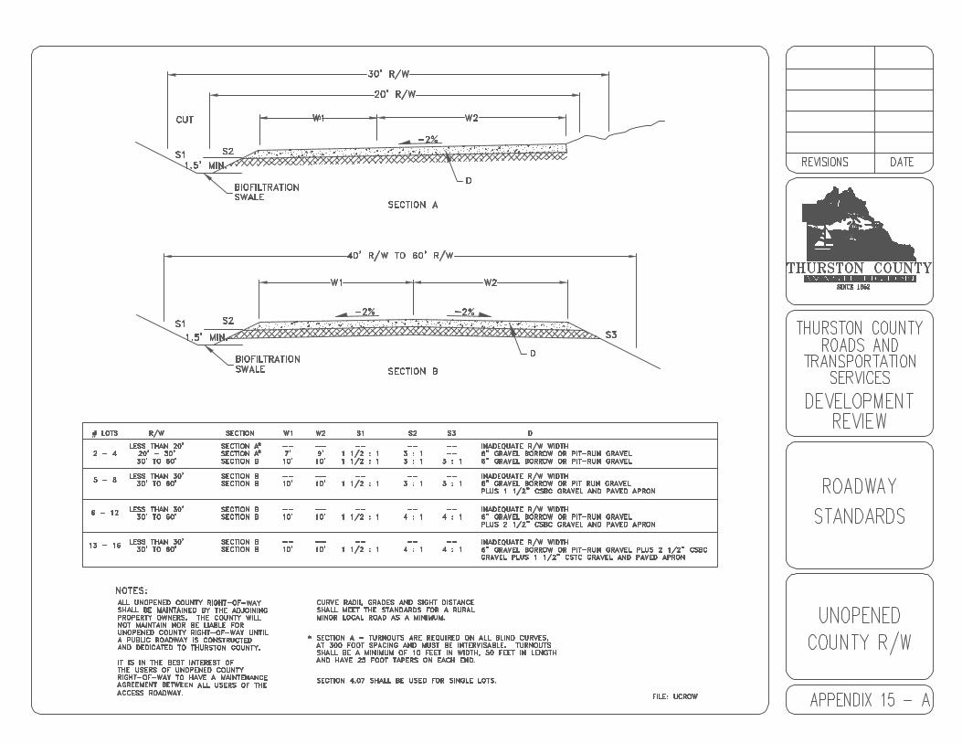
16-1
CHAPTER 16URBAN FEATURES
16.00 URBAN FEATURES
16.01 General16.02 Design Standards16.03 Sidewalks, Curb and Gutter16.04 Cement Concrete Curb and Gutter16.05 Curb Access Ramps16.06 Staking16.07 Testing16.08 Bikeways
Appendix 16 - A Cement Concrete DrivewayAppendix 16 - B SidewalkAppendix 16 - C Cement Concrete Curb, Gutter and WalkAppendix 16 - D Expansion Joint and Score MarksAppendix 16 - E Curb Ramp SamplesAppendix 16 - F Curb Ramps Type “A” and “B”Appendix 16 - G Curb Ramp Type “C”Appendix 16 - H Curb Ramp Type “D1"Appendix 16 - I Curb Ramp Type “D2"Appendix 16 - J Curb Ramp Type “E”Appendix 16 - K Curb Ramp Type “F”Appendix 16 - L Curb Ramp Type “G”Appendix 16 - M Cement Concrete Curb and GutterAppendix 16 - N Typical Cross-Walk DimensionsAppendix 16 - O Far-side Bus PulloutAppendix 16 - P Class II BikewayAppendix 16 - Q Entry/Exit DetailAppendix 16 - R Minor Local & Local Roadway SectionAppendix 16 - S Collector Roadway SectionAppendix 16 - T Arterial Roadway SectionAppendix 16 - U Elderberry Access Detail
16-2
16.00 URBAN FEATURES
16.01 General
All properties within the Grand Mound Urban Growth Area shall have cementconcrete curb, gutter and sidewalks constructed along the abutting private andpublic roads as shown on the typical roadway cross sections. Bikeways shallalso be constructed in locations shown on the Comprehensive Bike Plan. Newconstruction, alterations and improvements which constitute 25 percent or moreof the value of the existing real property improvements shall also have cementconcrete curb, gutter, sidewalks and bikeway (if applicable) constructed alongthe abutting private and public roads. All existing and proposed accesses ontothe roadways within the Grand Mound Urban Growth Area shall be evaluated forconformance with these Standards.
16.02 Design Standards
Plans for the construction of sidewalks, curb and gutters shall be submitted aspart of the plans when applicable.
The County has set forth minimum Standards for the Grand Mound UrbanGrowth Area as outlined in Appendices 16-A through 16-U which shall be met inthe design and construction of sidewalks, cross-walks, bus pullouts, bikeways,cement concrete curb and gutter. Because these are minimum Standards, theymay be modified by the Engineer when it is felt that circumstances requireincreased or decreased widths.
16.03 Sidewalks, Curb and Gutters
Sidewalks shall be constructed of air entrained Type II Portland Cement Class3000 in accordance with the requirements of Section 6-02 of the StandardSpecifications. The thickness of the sidewalk shall be 6 inches in drivewaylocations and 4 inches in all other areas. The width of the sidewalk shall bemeasured from the back of the curb and gutter to the back of the sidewalk.
A. Arterial, Collector and Local Roads. Sidewalks, curb and gutters shall berequired on both sides of all roads interior to the development, includingcul-de-sacs. Sidewalks, curb and gutters shall also be required on allroads abutting the development.
B. The design and construction of all sidewalks, curb and gutters shall meetthe Standards set forth in Appendices 16-A through 16-U.
The width of the sidewalks shall be shown in the road design drawings. The Engineer shall require that the design of all sidewalks provides for agradual rather than abrupt transition between sidewalks of different widthsor alignments.
16-3
C. Form and subgrade inspection by the County is required before thesidewalk is poured.
D. Monolithic pour of curb and sidewalk will not be allowed.
16.04 Cement Concrete Curb and Gutter
Cement concrete curb and gutter shall be used for all road edges unlessotherwise approved by the Engineer. All curb and gutters shall be constructed ofType II Portland Cement Class 3000 as shown in Appendix 16-M.
Extruded curb and gutter per Standard Specifications is allowed.
Form and subgrade inspection by the County is required before the curb andgutter is poured.
16.05 Curb Access Ramps
All sidewalks must be constructed to provide for access ramps in accordancewith the Standards of State law.
Curb access ramps shall be constructed of Type II Portland Cement Class 3000. Form and subgrade inspection by the County is required before the handicapramp is poured.
16.06 Staking
All surveying and staking shall be performed by an engineer or surveying firmcapable of performing such work. The engineer or surveyor directing such workshall be licensed by the State of Washington.
A preconstruction meeting shall be held with the County prior to commencingstaking. All construction staking shall be inspected by the County prior toconstruction.
The minimum staking of curb, gutter and sidewalk shall be as follows:
Stake top back of sidewalk or top back of curb at a consistent offset for verticaland horizontal alignment every 25 feet or 50 feet in tangent sections.
Staking shall be maintained throughout construction.
16.07 Testing
Testing shall be required at the applicant’s or contractor’s expense on allmaterials and construction as specified in the Standard Specifications.
16-4
At a minimum, one slump test and 2 test cylinders shall be taken once per day.
In addition, the County shall be notified before each phase of sidewalk and curbconstruction commences.
16.08 Bikeways
The minimum design Standards for bikeways shall be as defined in the “WSDOTDesign Manual,” Section 1020, Facilities for Non-motorized Transportation.
Class II Bike Paths are required within the Grand Mound Urban Growth Area asshown on the Comprehensive Bike Plan. Class II Bike Paths are those in whicha portion of the motor vehicle roadway is designated by signs and pavementmarkings for bicycle use. These facilities are adjacent to the motor vehicleroadway.
Bikeways may also be required when the traffic analysis or traffic planningindicates substantial bicycle usage which would benefit from a designatedbicycle facility as determined by the Engineer except where noted herein.