19531 - telematics - 5th tutorial - llc vs. mac, hdlc, flow control
TRANSCRIPT

19531 - Telematics5th Tutorial - LLC vs. MAC, HDLC, Flow Control, E2E-Arguments
Bastian Blywis
Department of Mathematics and Computer ScienceInstitute of Computer Science18. November, 2010
Institute of Computer Science – Telematics Tutorial – 18. November, 2010 1

Outline
1. Network Topologies
2. Reducing the Overhead
3. Efficiency of Stop-and-Wait
4. LLC vs. MAC
5. Flow Control
6. Sliding Window Mechanism
7. Sliding Window and Data Rate
8. Sliding Window
9. HDLC vs. PPP
10. The End–to–End Argument
Institute of Computer Science – Telematics Tutorial – 18. November, 2010 2

Network Topologies
Consider the following four network topologies, each withn nodes:
– Star– Fully Meshed– Unidirectional Ring– Bidirectional Ring
Give a formula to calculate the minimum, maximum, andaverage number of hops between any two nodes for anynumber n.
?? ?Institute of Computer Science – Telematics Tutorial – 18. November, 2010 3
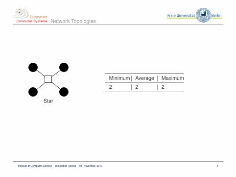
Network Topologies
Star
Minimum Average Maximum
2 2 2
Institute of Computer Science – Telematics Tutorial – 18. November, 2010 4

Network Topologies
Fully Meshed
Minimum Average Maximum
1 1 1
Institute of Computer Science – Telematics Tutorial – 18. November, 2010 5

Network Topologies
Unidirectional Ring
Minimum Average Maximum
1
1n − 1
n−1∑i=1
i =n2
n-1
Institute of Computer Science – Telematics Tutorial – 18. November, 2010 6

Network Topologies
Bidirectional Ring
Min. Average Maximum
1 if n even:
2 ∗∑ n
2 −1i=1 i + n
2n − 1
=n2
4n − 4
if n odd:
2 ∗∑ n−1
2i=1 i
n − 1=
n + 14
if n even:
n2
if n odd:
n − 12
Institute of Computer Science – Telematics Tutorial – 18. November, 2010 7

Reducing the Overhead
– As you have learned, frames (often) consist of datathat is framed by special flag bytes (start and stop).
– Discuss if the stop flag can be omitted to save onebyte as the start flag of the succeeding frame canbe used to implicitly mark that the previous framehas ended.
Start Data1 Stop Start Data2 Stop. . .
=⇒
Start Data1 Start Data2 . . .
?? ?Institute of Computer Science – Telematics Tutorial – 18. November, 2010 8

Reducing the Overhead
– What happens when there is no next frame or a long gap?– How can the receiver differentiate noise from data?
Start Data1 Start Data2 . . .? . . .Start Data3
Some Alternative Approaches:– Length field the header– Three-state logic (pull-ups/downs, output enable)– Out of band signaling, separate clock line
Institute of Computer Science – Telematics Tutorial – 18. November, 2010 9

Efficiency of Stop-and-Wait
– Assume a channel with a bit rate of 1 Mbps and adelay of 20 ms.
– A Stop-and-Wait protocol is used whichunfortunately introduces waiting times and thus alow efficiency.
– The efficiency is dependent on the size of theframes.
– Determine the frame size for which the efficiency is50%.
?? ?Institute of Computer Science – Telematics Tutorial – 18. November, 2010 10

Efficiency of Stop-and-Wait
– Using the Stop-and-Wait protocol, only one frame is on the line at a time– Acknowledgement has to arrive before next frame is sent– Assumptions
– Processing times are negligible– Acknowledgements are always piggybacked– Packets in both directions have the same size
– efficiency ≡ utilization in script (slide 4.70)
efficiency = length/(length + bitrate× RTT) (1)
0.5 = length/(length + 106 bps× 40× 10−3) (2)
0.5 = length/(length + 40× 103 bits) (3)
length = 40× 103 bits (4)
Institute of Computer Science – Telematics Tutorial – 18. November, 2010 11

LLC vs. MAC
Discuss the difference tasks of the LLC and MAC.
Background – Problem Statement:– Several data link layer protocols exist– Data link layer provides different services to the
network layer– Consistent primitives to the network layer are
desired
?? ?Institute of Computer Science – Telematics Tutorial – 18. November, 2010 12

LLC vs. MAC
Data link layer (often) consists of two sublayers:– Logical Link Control (LLC)– Media Access Control (MAC)
LLC– Specified in IEEE 802.2 and adopted by the ISO/IEC and redesignated as
ISO/IEC 8802-2:1998– Hides differences between various kinds of networks, example: Token ring
network can be connected (bridged) with Ethernet network– Single format and interface to the network layer– Format, interface, and protocol closely based on HDLC– LLC header is prepended to network layer packet before inserting into payload
field of, e.g., 802.3 frame– Services
– Unreliable datagram service (unacknowledged and connectionless)– Acknowledged datagram service (connectionless)– Acknowledged connection-oriented service
Institute of Computer Science – Telematics Tutorial – 18. November, 2010 13

LLC vs. MAC
LLC Classes– Class 1
– data-link-connectionless-mode service– Class 2
– data-link-connectionless-mode service– data-link-connection-mode service
– Class 3– data-link-connectionless-mode service– acknowledged-connectionless-mode service
– Class 4– data-link-connectionless-mode– data-link-connection-mode service– acknowledged-connectionless-mode service
Institute of Computer Science – Telematics Tutorial – 18. November, 2010 14
LLC vs. MAC
MAC– Handles access to shared medium– Contention for the medium access by all stations– Different MAC approaches for different network technologies– Network Allocation Vector (NAV) can be used for power management (if available)
Institute of Computer Science – Telematics Tutorial – 18. November, 2010 15

LLC vs. MAC
Figure: IEEE Architecture
Institute of Computer Science – Telematics Tutorial – 18. November, 2010 16

Flow Control
Repeat and discuss the task of flow control. ?? ?Institute of Computer Science – Telematics Tutorial – 18. November, 2010 17

Flow Control
– Control data flow between stations– Protect slow receiver from fast sender– Approaches
– Feedback-based flow control– Rate-based flow control
– Different strategies when acknowledgments are not received until timeout– Can enable reliable data communication
Institute of Computer Science – Telematics Tutorial – 18. November, 2010 18

Sliding Window Mechanism
– Consider some host-to-network technology whereeach frame contains a sequence number SEQ aswell as an acknowledgement number ACK.
– The acknowledgement number acknowledges allframes up to ACK-1.
– Both numbers are represented by M bits and thusall calculations are modulo log2(M).
?? ?Institute of Computer Science – Telematics Tutorial – 18. November, 2010 19
Sliding Window Mechanism
How many frames can be sent before at least one ac-knowledgement has to be received? ?? ?Institute of Computer Science – Telematics Tutorial – 18. November, 2010 20

Sliding Window Mechanism
The maximum window size is M − 1. With a window size of M, the following twoscenarios can not be distinguished by host A for W = M = 4:
A B0
1
2
3
0
ACK 1
ACK 1
A B0
1
2
3
0
ACK 1
ACK 1
Timeout
Note: In real networks there is no guarantee that the delay equal in both directions!
Institute of Computer Science – Telematics Tutorial – 18. November, 2010 21
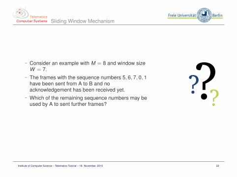
Sliding Window Mechanism
– Consider an example with M = 8 and window sizeW = 7.
– The frames with the sequence numbers 5, 6, 7, 0, 1have been sent from A to B and noacknowledgement has been received yet.
– Which of the remaining sequence numbers may beused by A to sent further frames?
?? ?Institute of Computer Science – Telematics Tutorial – 18. November, 2010 22

Sliding Window Mechanism
– Frames with the sequence numbers 5, 6, 7, 0, 1 have been sent– The frames with sequence numbers 2 and 3 can be sent without getting an
acknowledgement: M − 1 = 7– 5 frames have been sent⇒ last used sequence number + {1,2}
0
1
2
34
5
6
7
Institute of Computer Science – Telematics Tutorial – 18. November, 2010 23

Sliding Window Mechanism
Which sequence numbers may be used for furtherframes, if acknowledgements are received with:
1. ACK = 2
2. ACK = 6
3. ACK = 5
List the acknowledged sequence numbers and the win-dow of remaining sequence numbers.
?? ?Institute of Computer Science – Telematics Tutorial – 18. November, 2010 24

Sliding Window Mechanism
– Received ACK = 2– Acknowledged: 5, 6, 7, 0, 1– Window: 2, 3, 4, 5, 6, 7, 0
0
1
2
34
5
6
7
(a) Previous State
0
1
2
34
5
6
7
(b) Received Acknowledgement
Institute of Computer Science – Telematics Tutorial – 18. November, 2010 25

Sliding Window Mechanism
– Received ACK = 6– Acknowledged: 5– Window: 2, 3, 4
0
1
2
34
5
6
7
(c) Previous State
0
1
2
34
5
6
7
(d) Received Acknowledgement
Institute of Computer Science – Telematics Tutorial – 18. November, 2010 26
Sliding Window Mechanism
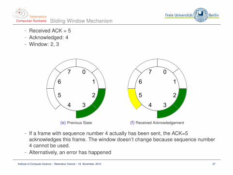
– Received ACK = 5– Acknowledged: 4– Window: 2, 3
0
1
2
34
5
6
7
(e) Previous State
0
1
2
34
5
6
7
(f) Received Acknowledgement
– If a frame with sequence number 4 actually has been sent, the ACK=5acknowledges this frame. The window doesn’t change because sequence number4 cannot be used.
– Alternatively, an error has happened
Institute of Computer Science – Telematics Tutorial – 18. November, 2010 27

Sliding Window and Data Rate
– Consider a host-to-network technology with asliding window mechanism and a window size ofW = 7.
– The frames can have a size of up to 1,500 bytesand the round trip time between two hosts is 50 ms.
– Calculate the maximum data rate that can beachieved.
?? ?Institute of Computer Science – Telematics Tutorial – 18. November, 2010 28
Sliding Window and Data Rate
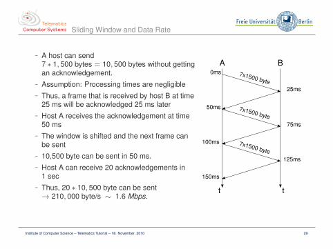
– A host can send7 ∗ 1, 500 bytes = 10, 500 bytes without gettingan acknowledgement.
– Assumption: Processing times are negligible– Thus, a frame that is received by host B at time
25 ms will be acknowledged 25 ms later– Host A receives the acknowledgement at time
50 ms– The window is shifted and the next frame can
be sent– 10,500 byte can be sent in 50 ms.– Host A can receive 20 acknowledgements in
1 sec– Thus, 20 ∗ 10, 500 byte can be sent→ 210, 000 byte/s ∼ 1.6 Mbps.
Institute of Computer Science – Telematics Tutorial – 18. November, 2010 29

Sliding Window and Data Rate
– In reality you have to consider the processingtimes of both hosts
– 1,500 byte = 12,000 bit take about 120 µs to“get the frame on the wire” with Fast Ethernet(100 MBit/s)
– The first frame is received by host B after25.12ms.
– Assumption: The ACK is sent immediatelywithout any additional delay
– Assumption: ACK frames without data are lessthan 100 bit long and it takes about 1µs sentthe frame
– Thus, after 50.121ms host A can move thewindow by one position and sent the next frame
– . . .
Institute of Computer Science – Telematics Tutorial – 18. November, 2010 30

– Assume a geostationary satellite sends frames of1000 bits over a channel with a bit rate of 1 Mbps.
– The frame take 270 ms to arrive at the station onearth.
– Calculate the maximum achievable efficiencyusing a
– Stop-and-Wait protocol– Sliding Window protocol with window size 13
– The acknowledgements are always piggybacked ondata frames.
?? ?Institute of Computer Science – Telematics Tutorial – 18. November, 2010 31
– Transmission starts at t=0– Station on earth receives 1st frame at t=271 ms– Station replies at t=272 ms– Reply from station arrives at t=542 ms at the satellite– k Frames can be sent in 542 ms until an acknowledgement is required to proceed– Efficiency is k/542
– k=1 (Stop-and-Wait): efficiency = 1/542 = 0.18%– k=13 (Sliding Window): efficiency = 13/542 = 2.40%
Institute of Computer Science – Telematics Tutorial – 18. November, 2010 32

Sliding Window
Why do we need preferably a full-duplex connection forsliding window protocols? ?? ?Institute of Computer Science – Telematics Tutorial – 18. November, 2010 33

Sliding Window
– Without a full-duplex connection, there is only limited parallelization– Data and acknowledgements should be on the medium at the same time– The rate and delay at which the acknowledgements arrive, significantly
determines the performance (remember this when we will discuss TCP!)– In many scenarios both stations want to send data at the same time– Parallelization is an important motivation for sliding window protocols
Institute of Computer Science – Telematics Tutorial – 18. November, 2010 34

HDLC vs. PPP
– Compare the HDLC and PPP protocols.– Specify appropriate metrics for the comparison. ?? ?
Institute of Computer Science – Telematics Tutorial – 18. November, 2010 35

HDLC vs. PPP
HDLC PPP
Origin based on SDLC Inspired by HDLC
Standardization ISO IETF
Implementation hardware software
Framing Synchronous or asyn-chronous
depends on framing
Stuffing bit byte
Services connection-oriented, con-nectionless
connection-oriented
Modes point-to-point or point-to-multipoint
point-to-point
Checksum CCITT CRC-16 depends on framing
Discuss further differences!
Institute of Computer Science – Telematics Tutorial – 18. November, 2010 36

HDLC vs. PPP
Examples for PPP encapsulation
Simpson PPP in HDLC-like FramingRFC 1662, 1994
Mamakos et al. A Method for Transmitting PPP Over Ethernet (PPPoE)RFC 2516, 1999
Simpson PPP over SONET/SDHRFC 1619, 1999
Gross et al. PPP Over AAL5RFC 2364, 1998
Simpson PPP over ISDNRFC 1618, 1994
PPP Connection Establishment
Simpson PPP Challenge Handshake Authentication Protocol (CHAP)RFC 1994, 1996
Simpson PPP LCP ExtensionsRFC 1570, 1994
Institute of Computer Science – Telematics Tutorial – 18. November, 2010 37

The End–to–End Argument
– Read the article End-to-end arguments in systemdesign by Saltzer et al.
– Discuss the ideas of the end–to–end argument andwhich functions/services should be provided onparticular layers of the reference model. ?? ?
Institute of Computer Science – Telematics Tutorial – 18. November, 2010 38

The End–to–End Argument
Motivation:– Context: Protocol design– Distributed system with different layers– Functions that might be implemented on multiple levels of the protocol stack– Key question: Where to place which function?
End–to–End (E2) Argument:– Implementing these functions at low level may be redundant or provides little
usefulness– Functions in question should be implemented at the endpoints of the
communication system– Example: Congestion control at endpoints
Discussion:– E2E-Argument does not tell at which layer to place the functions– Consider a trade-off between costs and performance
Institute of Computer Science – Telematics Tutorial – 18. November, 2010 39

The Last SlideTM
Thank you for your attention.Questions?
Institute of Computer Science – Telematics Tutorial – 18. November, 2010 40