1952 - 53 hydra-matic supplement manualhudsonterraplane.com/tech/1952/1952-53_hydra-matic... ·...
TRANSCRIPT


FOREWORD
This Hydra-Matic Transmission Service Manual Supplement when used with the Hudson Hydra-Matic Transmission Service Manual, provides complete information for the proper servicing of all Hydra-Matic Transmissions used in Hudson Cars from 1951 thru 1953, covering transmission models H-50, H-51, J-51, H-52, J-52, Z-52, H-53, J-53 and Z-53.
This supplement covers only those design changes which differ for the H-53, J-53, Z-52 and Z-53 transmissions and the resultant changes in operation, oil flow and repair procedures affected by these design changes. The principal changes involve the transmission case, front servo, rear pump and governor oil delivery pipe.
The dis-assembly, inspection and assembly procedures for the new front servo and control valve are covered in this supplement. All other units of the H-53, J-53, Z-52 and Z-53 transmissions are similar in design to those used in the H-52, T-52 Hydra-Matic transmissions and are covered in detail in the Hudson Hydra-Matic Transmission Service Manual.
Hydraulic action and oil flow for the new transmissions are illustrated in simplified schematic line drawings.
HUDSON MOTOR CAR CO.DETROIT 15, MICHIGAN
LITHO. IN U.S.A. STOCK 8 - 53 No. T-191
1

2
ALPHABETICAL INDEX
ADJUSTMENTS - LINKAGE Manual Control Linkage Neutral Safety Switch Throttle Control Linkage Adjustment 1C - 2C Throttle Control Linkage Adjustment 1C - 2C With Twin Carburetors Throttle Control Linkage Adjustment 4B, 4C, 5B and 5C Throttle Control Linkage Adjustment 4B, 5B, 4C, 5C With 262 Engine With Twin Carburetors Throttle Control Linkage Adjustment 6B, 7B and 7C Throttle Control Linkage Adjustment 6B, 7B and 7C With Twin Carburetors
CHANGES IN THE HYDRAULIC CONTROL CIRCUIT Front Servo Operation Overcontrol Valve Action Shuttle Valve Action
CONTROL VALVE ASSEMBLY Assembly Changes Cleaning and Inspection Disassembly
DIAGNOSIS AND TESTING Clashes When Shifted to "R" - (51-53) Intermittent Slip in All Ranges Jumps Out of Reverse Lock Up In Reverse (Light Throttle or Coast) Misses 2nd and 4th Misses 1st and 3rd Noise No 3 -2 Forced Downshift No 4 -3 Forced Downshift No Drive No Drive After Shifting from "R" No Drive When Engine is First Started No Reverse Slips No Upshifts Above 1st Oil Leaks Rough 3 - 2 or 3 -1 Downshift (Closed Throttle) Rough 4 - 3 Forced Downshift Rough Downshift After Car is Stopped Rough Shifting "N" to "R" Selector Lever Won't Go Into "R" (Engine Running) Selector Won't Go Into "R" (Engine Off) Slips - I - 2 Misses 2nd Slips - 2 - 3 Slips - 3 - 4 Slips - 4 - 3 Forced Downshift Slips - Heavy Throttle Upshifts
394747
39
40
41
42
42
45
5576
252842725
323535353434343633333535363434363334343635353233333332
SUBJECT PAGE

3
ALPHABETICAL INDEX--CONTINUED
DIAGNOSIS AND TESTING - CONTINUED Slips - Light Throttle Upshifts Transmission Shifts or Hunts With Vehicle Not Moving Unable to Drive Engine By Pushing or Towing Upshifts to 3rd in "LO" at Low Speeds Upshifts to 4th in "DR-3" at Low Speeds Will Not Lock In "R" With Engine Off (51 - 53) Will Shift Into "R" Above 12 M.P.H. Upshifts To High Upshifts To Low Upshifts Rough
FRONT SERVO Assembly Disassembly Operation Removal
HYDRA -MATIC CHANGES FOR - Z-52, H-53, J--53 and Z-53 Control Valve Assembly Pressure Regulator Pump - Rear Servo - Front Servo - Rear Transmission Case
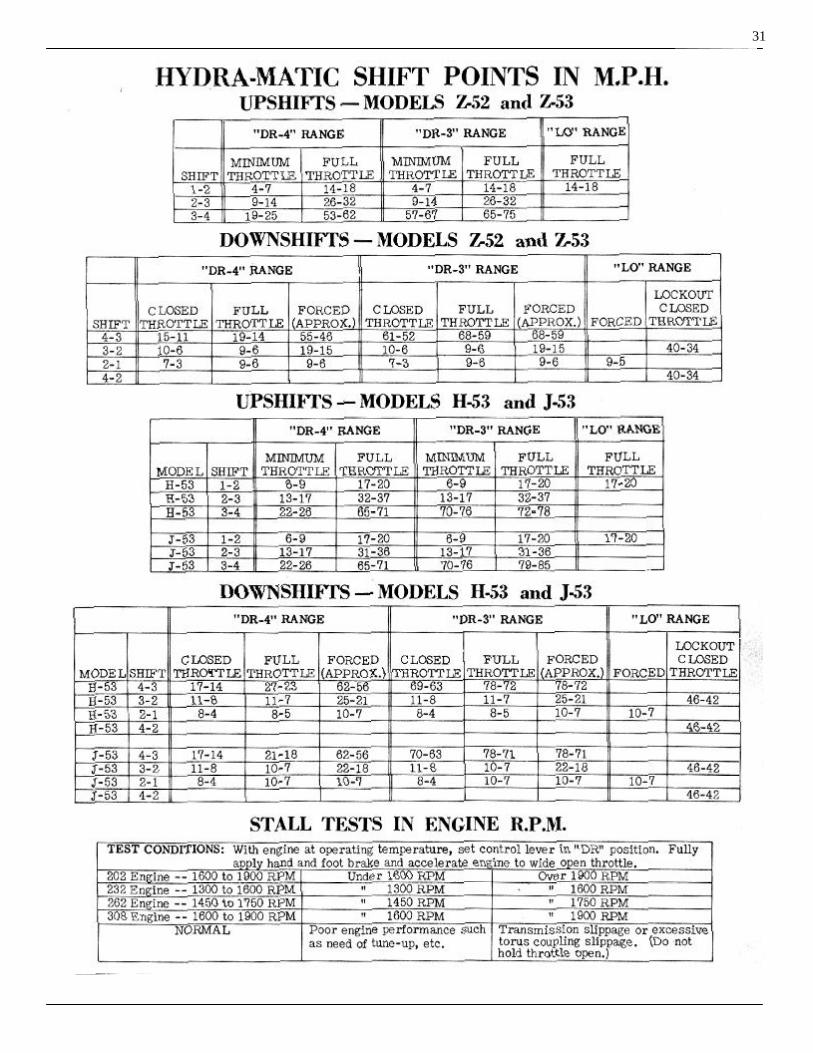
HYDRA-MATIC SHIFT POINTS IN M.P.H.
HYDRAULIC ACTION Compensator Pressure Downshift - Forced (2 - 1) Downshift - Forced (3 - 2) Downshift - Forced (4 - 3) First Speed - Hydraulic Action Fourth Speed - Hydraulic Action Modulated Main Line Pressure Neutral - Engine Not Running Neutral - Engine Running Regulated T.V. Pressure Reverse - Hydraulic Action Second Speed - Hydraulic Action Second Speed - "LO" Third Speed - Hydraulic Action Third Speed - "Drive - 3"
OVERCONTROL VALVE
OVER-RUN CONTROL VALVE Pressure Regulator Rear Pump Rear Servo
STALL TESTS IN ENGINE R.P.M
TORQUE CHART
3232353633333636323232
42422522
4444444
31
81821201910131789171611151214
7
4444
31
48
SUBJECT PAGE

4
HYDRA-MATIC CHANGESFOR Z-52 H-53 J-53 Z-53
TRANSMISSION CASE
To simplify service the main line exhaust valve has been removed from the transmission case and added to the front servo valve body. The main line exhaust valve sleeve and the valve sleeve remover tool have been eliminated, the one-two shift oil passages have been altered.
FRONT SERVO
The front servo has been changed by adding a valve body which contains the line exhaust valve and over-run control valves. In the 52 transmissions the line exhaust was located in the case and the over-run control valve in the front servo body.
This new location for these valves sim- plifies service by combining them into an easily accessible valve body.
On past models, only two bolts held the release cylinder to the servo body.
Three bolts attach the release cyl-inder to the servo body to improve sealing and eliminate the use of a gasket. The front servo piston assembly includes only the apply piston and compensator piston, the release piston is now a separate part. A booster has been added which acts on the release piston. This improves band release and clutch apply action.
The orifice in the 4-3 downshift valve has been eliminated. This orifice is now located in a passage by-passing the valve. The slot in the end of the valve and the hair pin retainer have been eliminated.
REAR SERVO
The design and operation of the quick dump in the rear servo has been changed.One-two shift oil closes the rear servo exhaust valve and spring pressure opens it.These changes provide smoother "DR" to"LO" and quicker neutral to "DR" shifts. Faster rear servo action for rocking can still be obtained by shift-ing from Reverse to Drive range.
CONTROL VALVE ASSEMBLY
The 3-4 shift valve assembly has been replaced by a new 3-4 shift valve eliminating the 1 o c k out valve assembly and auxiliary shift spring.
A new shuttle has been added to the control valve which allows either detent or "DR-3" oil to close the 3-4 shift valve.
A compensator auxiliary plug has been added to all H-53, J-53 and Z-53 control valve outer valve bodies to improve shift characteristics.
A double transition valve spring is used in the J-53 and Z-53 control valve assemblies. The double transition valve spring is not used in the 11-53 control valve assembly.
A new leaf type check valve with a metering orifice replaces the orifice which was drilled in the outer valve body.The new control valves can be identified as follows:
The 11-53 control valve assembly has the numeral "4" stamped on the outward end of the T.V. shaft.
The J-53, Z-52 and Z-53 control valves have the numeral "1" stamped on the outward end of the T.V. shaft.
REAR PUMP
The rear pump has been designed for greater capacity. This is accom-plished by an increase in the width of the pump gears. As a result, lower starting speeds are obtainable when it is necessary to tow or push the vehicle.
PRESSURE REGULATOR
A new pressure regulator plug is now being used. Higher pressure T.V. and pressure regulator plugs are used which increases main line pressure at all speeds (approximately 10 pounds more) under full throttle. The new plug shown at "B" has a milled groove in the outside diameter of the bore of the pressure regulator plug and the undercut of the T.V. plug is tapered at both ends.

5
PRESSURE REGULATOR IDENTIFICATIONFIGURE A
CHANGES IN THEHYDRAULIC CONTROL
CIRCUIT
FRONT SERVO - OPERATION
The operation of the over-run control valve has been changed to improve shift timing. With the car speed below approx-imately 20 miles per hour, the over-run control valve spring force is greater than the G-1 oil force, and compensator is directed to the compensator piston. When the car speed exceeds approximately 20 miles per hour, governor pressure overcomes the spring pressure to move the overcontrol valve, cutting off compensator oil and directing front band apply oil to the compensator piston. Thus at highway speeds over 20 miles per hour where over-run engine braking may be desired, two servo apply areas are supplied with line pressure to prevent band slippage. Below 20 miles per hour line pressure is directed only to the apply piston, with the pressure to the compensator piston varied to suit the engine output. This is illustrated on Figures 1 & 2.
As soon as the front unit shifts to direct drive, front band release oil assists the overrun control valve spring to overcome G-1 pressure. Therefore, whenever the front unit is in direct
FRONT SERVO - G-1 OILCAR SPEED BELOW 20 MPH
FIGURE 1
FRONT SERVO - G-1 OILCAR SPEED ABOVE 25 M.P.H.
FIGURE 2
direct drive, regardless of car speed, only compensator oil is allowed to the compensator piston, Figure 3.
The supply oil is forced to go through the passage with a restricted orifice, thus slowing the front servo apply at speeds above 25 miles per hour to give the engine time to speed up for a smooth forced 4-3 downshift.

6
FRONT SERVO - G-1 OILFIGURE 3
SHUTTLE VALVE ACTION
The addition of a shuttle valve in the H-53, J-53, Z-53 control valve assembly has eliminated the need for a 3-4 lockout valve assembly and a 3-4 auxiliary spring. The shuttle valve per m it s the use of the same area for the detent oil, "DR-3" oil and the regulated "T.V." oil. With the manual valve in "DR-3" position, "DR-3" oil moves the shuttle valve away from the inner valve body, blocking the detent oil passage and allowing"DR-3" oil to close the 3-4 shift valve, Figure 4.
DRIVE 3 - THIRD SPEEDFIGURE 4
With the manual valve in "DR-4" and the accelerator pedal completely de-pressed for a forced downshift, detent oil positions the shuttle valve toward the inner valve body, blocking "DR-3" oil passage and allowing detent oil to pass through the 3-4 shift valve, Figure 5.
DRIVE 4 - THIRD SPEEDSHUTTLE VALVE 4-3 DOWNSHIFT
FIGURE 5
Regulated "T.V." action is not affected by the shuttle valve as long as detent oil and "DR-3" oil are not present, Figure 6.
DRIVE 4 - THIRD SPEEDFIGURE 6

7
OVERCONTROL VALVE
The overcontrol valve prevents the car remaining in third speed above 75 M.P.H. (selector lever in ("DR-3"), preventing excessive engine speeds.
It also prevents a 3-2 downshift, when the selector lever is moved to"LO" at car speeds above 46 M.P.H., prevent-ing engine over-speeding.
"DR-4 or DR-3" CAR SPEED APPROX.BELOW 75 M.P.H.
FIGURE 7
With the selector lever in the "DR-4" or "DR-3" position and the car speed below approximately 75 M.P.H., G-2 oil is directed against the overcontrol valve. Since the oil pressure at this speed is not sufficient to overcome the overcontrol valve spring pressure, G-2 oil is directed into the G-1, G-2 passage. G-1 oil is then blocked by the over- control valve, Figure 7. With the selector lever in the "DR-4 or DR-3" position and the car speed above approximately 75 M.P.H., G-2 oil becomes great en ough to close the overcontrol valve. G-1 pressure now is direct ed into the G-1, G-2 passage. Since G-1 pressure is greater than G-2, the difference is great enough to act on the 3-4 Governor Plug to open the 3-4 shift valve, Figure 8. At high vehicle speeds, a downshift to "LO" range would cause excessive engine
"DR-4 or DR-3" CAR SPEED APPROX.ABOVE 75 M.P.H.
FIGURE 8
engine speeds. To prevent this, "LO" oil along with G-2 oil moves the overcontrol valve up at speeds above approximately 46 M.P.H., G-1 oil then flows into Gl-G2 oil passage to the 2-3 auxiliary plug and keeps the 2-3 shift valve from closing to prevent engine over-speed-ing, Figure 9.
"DR-4 or DR-3" CAR SPEED APPROX.ABOVE 46 M.P.H.
FIGURE 9

8
HYDRAULIC ACTION IN NEUTRAL(Engine Not Running)
FIGURE 10
HYDRAULIC ACTION IN THE TRANSMISSIONII-53, J-53, Z-52 Z-53
HYDRAULIC ACTION INNEUTRAL
(Engine not Running)
When the engine is not running and the car is standing there is no oil pressure. Basically the oil circuit is the same as the 11-52, J-52 and Z-53 Transmission.
Since there is no oil pressure, the front unit band and clutch are held in the released position by their respec-tive release springs. The rear servo band is spring applied and oil released. When there is no oil pressure the rear servo band is applied and the release springs hold the rear clutch piston in the released position, Figure 10.

9
HYDRAULIC ACTION IN NEUTRAL(Engine Running)
FIGURE 11
HYDRAULIC ACTION INNEUTRAL
(Engine Running)
With the manual valve in the neutral “N” positiong and he engien running, oil pressure is directed to the main line exhaust valve, closing the valve against spring pressure.
Front servo band apply oil is cut off by the manual valve and the front band and clutch are in the released position. Oil is also directed by the manual valve to the rear servo to release the rear band. The rear clutch is also released by the clutch release springs. With both bands and both clutches released the transmission is in neutral, Figure 11.

10
HYDRAULIC ACTION IN FIRST SPEEDFIGURE 12
HYDRAULIC ACTION INFIRST SPEED
When the manual valve is moved from neutral "N" to the "DR" position (either "DR-3" or "DR-4") oil is directed to the apply side of the front servo to apply the band and to the land of the 1-2 shift valve. Governor variable pressure is also
also directed to the 1-2 shift valve.
The front servo band is applied by oil pressure and the rear band is spring applied. Both the front and the rear unit clutches are spring released plac-ing the transmission in first speed, Figure 12.

11
HYDRAULIC ACTION IN SECOND SPEEDFIGURE 13
HYDRAULIC ACTION INSECOND SPEED
Governor pressure increases with increased vehicle speed. When sufficient governor pressure is attained the 1-2 shift valve is opened against spring pressure, directing main line pressure to the release areas of the front servo to release the front band. Oil is also
directed to the front unit to apply the clutch, placing the front unit in direct drive.
With no oil directed to the rear servo, the rear band is applied by spring pressure. There is no oil di-rected to the rear clutch unit, there-fore, the rear unit is in reduction and the transmission is in second speed, Figure 13.

12
HYDRAULIC ACTION IN THIRD SPEEDFIGURE 14
HYDRAULIC ACTION INTHIRD SPEED
Main line pressure from the manual valve is blocked by the 2-3 shift valve, held closed by spring pressure. G-1 governor oil pressure directed against the 2-3 governor plug and G-2 governor oil directed against the 2-3 auxiliary valve increases with car speed to a point where it is greater than spring pressure against the 2-3 shift valve. When the shift valve opens, oil is directed to the rear
the rear unit to release the rear band and apply the clutch.
At the same time, oil is directed against the large end of the double transition valve fo r c in g it inward, blocking oil that held the front unit in direct drive.
Front servo band apply pressure applies the front band and the front unit is in reduction and the rear unit is in direct drive the transmission is in third speed, Figure 14.
13
HYDRAULIC ACTION IN FOURTH SPEEDFIGURE 15
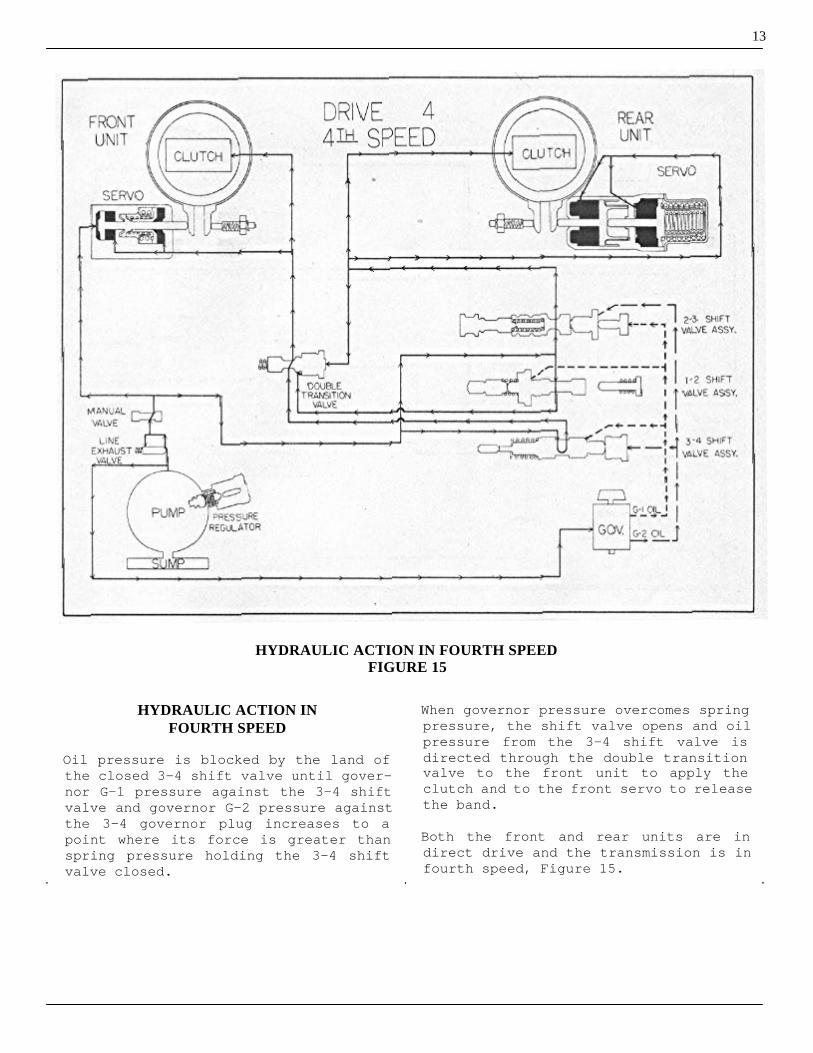
HYDRAULIC ACTION INFOURTH SPEED
Oil pressure is blocked by the land of the closed 3-4 shift valve until gover-nor G-1 pressure against the 3-4 shift valve and governor G-2 pressure against the 3-4 governor plug increases to a point where its force is greater than spring pressure holding the 3-4 shift valve closed.
When governor pressure overcomes spring pressure, the shift valve opens and oil pressure from the 3-4 shift valve is directed through the double transition valve to the front unit to apply the clutch and to the front servo to release the band.
Both the front and rear units are in direct drive and the transmission is in fourth speed, Figure 15.

14
HYDRAULIC ACTION - “DR-3” - THIRD SPEEDFIGURE 16
HYDRAULIC ACTION -"DR-3" -THIRD SPEED
When the selector lever is in the "DR-3" position, the manual valve directs line pressure to the same passages used in "DR-4" (fourth speed) position. Main line pressure is also directed to an area on the 3-4 governor plug and the 3-4 shift valve to assist the spring and throttle .pressure to hold the 3-4 shift valve closed to prevent the transmission from shifting into fourth speed, Figure 16. G-1 governor pressure is directed to the end of the over-run control valve. Below 20 M.P.H. over-run control valve spring pressure is greater than G-1 pressure and the
pressure and the passage is open direct-ing compensator pressure to the compen-sator piston. At speeds below 20 M.P.H., main line pressure is directed only to the apply piston, and compensator pres-sure to the compensator piston is varied in accordance with engine output.
At speeds above 20M.P.H. governor pressure overcomes over-run control valve spring pressure moving the valve to cut-off compensator p r e s s u r e and direct front band apply pressure to the compensator piston. At speeds over 20 M.P.H. where over-run engine braking is desired, the two front servo apply areas have line pressure present to prevent band slippage, Figure 16.

15
HYDRAULIC ACTION - "LO RANGE" - SECOND SPEEDFIGURE 17
HYDRAULIC ACTION —"LO RANGE" — SECOND SPEED
When descending steep grades where maximum braking power of the engine is desired, or when pulling through deep sand or steep grades, it is desirable to keep the vehicle operating in first and second speeds regardless of vehicle speed. This is accomplished by moving the selector lever to "LO" position directing main line pressure to the large area on the 2-3 auxiliary valve opposing governor pressure, thereby preventing the 2-3 shifter valve from opening, Figure 17. Main line pressure is also directed to the large area on the 2-1 detent plug opening the 1-2 shifter valve and putting the front unit in direct drive. Since the rear unit is in reduction at all times in "LO" range and the front unit is in direct drive, the transmis-sion is in second speed. Normally in ",LO" range there is only
second speed, however, when the acceler-ator is depressed through the detent, throttle pressure is sufficient to close the 1-2 shift valve and the °transmission will downshift to first speed.
G-1 governor pressure is also di-rected to the over-run control valve, however front servo release oil is directed to the opposite end of the over-run control valve to assist the over-run control valve spring to overcome G-1 governor pressure. When the over-run control valve is in this position, band apply oil to the second apply area of the front servo is blocked at the over-run control valve land and the compensator passage is open, direct-ing compensator pressure to the compen-sator piston.
With the front unit in direct drive, only compensator pressure is directed to the compensator piston, Figure 17.

16
HYDRAULIC ACTION IN REVERSEFIGURE 18
HYDRAULIC ACTION INREVERSE
When the selector lever is moved to the reverse "R" position, main line pressure from the manual valve is directed to the front servo to apply the band, Figure 18. Band apply pressure to the second apply area is blocked at the land of the over-run control valve (held in the released position by the over-run con-trol valve release spring). Main line pressure is also directed to the rear unit servo to release the rear band and to the pressure regulator booster plug to increase main line pressure sufficiently to apply the reverse cone clutch. Main line pressure is present at the parking blocker piston of the parking brake
brake bracket assembly. When the engine is stopped the main line exhaust valve is opened by spring pressure to rapidly exhaust the line pressure releasing the blocker piston and allowing the parking pawl to engage quickly with the teeth on the reverse internal gear to provide a parking brake.
At car speeds above 10 M.P.H., governor G-1 oil pressure exerted against the reverse blocker piston prevents shifting the selector lever to the reverse position. At car speeds below 10 M.P.H. reverse blocker piston, spring pressure is greater than governor G-1 pressure and the reverse blocker piston recedes, permitting the selector lever to be moved to the reverse position.

17
T.V., REGULATED T.V. AND MODULATED MAIN LINE PRESSUREFIGURE 19
REGULATED T.V. PRESSURE
Regulated T.V. Pressure from the T.V. regulator plug is directed to the 2-3 and 3-4 s h if valves and the 1-2 and 3-4 regulator plugs to aid the springs in holding the shift valves closed. "Regulated T.V. Pressure" varies with the amount of T.V. pressure. Therefore, the shifts will occur at very low speeds under light throttle and at higher vehicle speeds in proportion to the increased throttle opening, Figure 19.
MODULATED MAIN LINEPRESSURE
Modulated Main Line Pressure is obtained by directing T.V. Pressure behind the T.V. plug in the pressure regulator assembly. Additional pressure on the T.V. plug assists the pressure regulator spring to increase main line pressure. With T.V. pressure increasing with throttle opening, main line pres-sure must increase in proportion. Modu-lated main line pressure then allows a smooth application or engagement of the band or clutch during a light throttle opening, but also provides additional pressure to prevent slippage up on heavy throttle opening.

18
COMPENSATOR PRESSUREFIGURE 20
COMPENSATOR PRESSURE
Increased torque developed under rapid acceleration requires additional holding force to pre vent the bands from slipping on the drums. This pressure is obtained by directing T.V. pressure against the end of the compensator valve. Main line pressure metered through the compensator valve as compen-sator pressure is directed to the rear servo and, through the over-run control valve, to the front servo to assist main line pressure to prevent slippage when the bands are applied, Figure 20.At car speeds below 20 M.P.H. over-run control valve spring pressure is greater than governor G-1 pressure directed
against the end of the valve. Therefore, the compensator passage to the front servo is open. At speeds above 20M.P.H. governor G-1 pressure over- c ome s over-run control valve spring pressure. The valve is then forced back, closing the compensator passage and opening a passage past the valve to direct main line pressure to the second apply area of the front servo.
When the front unit is in direct drive, front band release oil is di-rected to the opposite end of the over-run control valve to assist the spring in opposing governor G-1 pres-sure. Therefore, only compensator pres-sure is directed to the compensator piston regardless of car speed.

19
FORCED 4-3 DOWNSHIFTFIGURE 21
FORCED 4-3 DOWNSHIFT
While driving in fourth speed it is sometimes desirable to shift the trans-mission t o third speed to obtain rapid acceleration. The "T" valve and the detent plug, parts of the throttle valve assembly, are utilized to accomplish the 4-3 downshift. When the accelerator pedal is fully depressed, the throttle valve is forced back until it contacts the detent at the wide open throttle position and a resistance is felt at this point. Depressing the accelerator further against the detent plug moves the "T" valve, throttle valve and detent plug back against de- tent pressure, Figure 21. As the "T" valve is moved, it reaches a position where main line pressure is
directed from the "T" valve to the shuttle valve. The shuttle valve is moved toward the inner valve body, blocking the "DR-3" oil passage and opening the passage from the shuttle valve to the back of the 3-4 shift valve forcing it closed against governor pressure. This action cuts off the pressure to the front unit clutch and the clutch is then released by spring pressure. Pressure is also cut off from the re- le a se side of the front servo and the front band is applied by band apply pressure. With the accelerator pedal fully depressed, throttle and spring pressure is sufficient to hold the valve closed until a high vehicle speed is reached. If the accelerator pedal i s released, the shift from third to fourth occurs when governor pressure overcomes the 3-4 spring pressure.

20
FORCED 3-2 DOWNSHIFTFIGURE 22
FORCED 3-2 DOWNSHIFT
When the accelerator pedal is de-pressed through the detent and the car is going slowly enough to obtain a 3-2 downshift main line pressure through the "T" valve will open the 3-2 detent plug and move the 2-3 shift valve to the closed position, Figure 22.
With the 3-2 detent plug opened, regu-lated T.V. pressure to the 2-3 shift valve is cut off. Main line pressure from the "T" valve flows past the large end of the 3-2 detent plug to close the 3-2 timing valve.
Regulated T.V. pressure (main line pres-
pressure at full throttle) is directed to a passage uncovered by the small end of the 3-2 detent plug. This passage delivers oil to the 1-2 shift valve through a large port to provide rapid application of the front clutch.
Because the 3-2 timing valve is closed, release oil from the rear servo exhausting through the 2-3 shift valve must flow through a small orifice at the timing valve shown in broken lines. This results in slow application of the rear band. Due to the rapid front clutch engagement and the slow appli-cation of the rear band, the transmis-sion will shift smoothly into second speed.

21
FORCED 2-1 DOWNSHIFTFIGURE 23
FORCED 2-1 DOWNSHIFT
At vehicle speeds below 10 M.P.H. a forced 2-1 downshift can be obtained in either "DR" or "LO" range. Regulated T.V. pressure which becomes main line pressure with wide open throttle opposes governor pressure on the land of the 1-2 shift valve, Figure 23. Regulated T.V. pressure forces the 1-2 shift valve closed, resulting in a shift from second
to first speed in the transmission. On a forced 2-1 downshift, main line pressure against the 2-1 detent plug would hold the shift valve open in "LO" range. Therefore, "T" oil on a forced 2-1 downshift is directed behind the 2-1 detent plug to move it back. Thus it is possible to provide a first speed start in low range by pressing the accelerator to the floor.

FRONT SERVO
NOTE: The new front servo can be removed for over-haul with the transmission either in or out of the car.
GOVERNOR OIL DELIVERY SLEEVE PIPEFIGURE 24
REMOVAL:
The removal procedure is the same as outlined for the H-52, J-52 and Z-52 transmissions and is given in detail in the HydraMatic Transmission Service Manual. It should be noted, however, that the governor oil delivery pipe between the front servo and the transmission case, Figure 24, H-53 - J-53 - Z-53 is not the same as the pipe used on the earlier transmissions and is not interchangeab1e. Do not bend a pipe from one model transmission to fit the other as this will result in kinking the pipe and restricting main line oil from the front servo to the governor.
Disassembly:
1. Remove the three bolts (1) attaching front servo release cylinder (2) to front servo body (8), Figure 25.
2. Remove the front servo release cylinder (2)
3. Remove booster spring (4), retract-ing spring retainer (5) and retract-ing spring (6).
4. Remove the release piston (3) from the release cylinder (2), Figure 26.5. Remove front servo band apply piston assembly (7) from front servo body (8).6. Remove the three screws attaching
the front servo valve body (18) to the front servo body and remove the front servo valve body.
NOTE: Remove the front servo valve body (18) care-fully to avoid loss of the rear pump check valve (10) and spring (9) (Figure 27).
DISASSEMBLING FRONT SERVORELEASE CYLINDER
FIGURE 25
REMOVING RELEASE PISTONFIGURE 26
FRONT SERVO VALVE BODY REMOVEDFIGURE 27
22

DISASSEMBLED VIEW OF FRONT SERVO Legend: FIGURE 28
23
1.2.3.4.5.6.7.
Release Cylinder Attaching ScrewsRelease CylinderBand Release PistonBooster SpringRetracting Spring RetainerRetracting SpringBand Apply Piston Assembly
8.9.
10.11.12.13.14.
Front Servo BodyRear Pump Ball Check Valve SpringRear Pump Ball Check ValveBand Adjusting Hole Plug4-3 ValveOverrun Control Valve Plug PinOverrun Control Valve Spring Plug
15.16.17.18.19.20.21.
Overrun Control Valve SpringOverrun Control ValveFront Servo Valve Body Attaching ScrewsFront Servo Valve BodyLine Exhaust ValveLine Exhaust Valve SpringLine Exhaust Valve Retainer
7. Remove the overrun control valve plug pin (13), spring plug (14), spring (15) and overrun control valve, (16) Figure 28.
8. Remove the line exhaust valve retainer (21), line exhaust valve spring (20) and the line exhaust valve (19).
9. Remove the 4-3 downshift valve (12)from the front servo body, Figure 29.
10. Remove the front servo band adjust-ing hole plug (11) from the servo body.
CLEANING AND INSPECTION:
1. Check the machined surfaces of the servo body (8), release cylinder (2) and servo valve body (18) for roughness or scoring.
CHECKING 4-3 VALVE FIGURE 2

2. Check for obstruction of the 4-3 downshift valve restrictor orifice.
3. Check servo for blocked or intercon-nected oil passages, Figure 30.
OIL PASSAGES - FRONT SERVOFIGURE 30
4. Check front band release piston (3), Figure 28, for scores, broken ring and ring freedom in release piston groove.
5. Check the 4-3 downshift valve (12) for free movement in the servo body bore.
6. Inspect the front servo retracting spring (6) and booster spring (4) for distortion or collapsed coils. Free length of the booster spring 61/64 of an inch and full length of the retracting spring is 1-33/64 inches.
7. Inspect the rear pump check valve seat, ball (10) and spring (9).
NOTE: The rear pump check valve seat has a small drill spot in the seat face. The spot acts as a rear pump pressure bleed. Be certain the check valve seat has this drill spot.
8. Check the over-run control valve (16) for free movement in the bore and for scoring.
9. Check the free length of the over-run control valve spring (15). Free length should be approximately 2".
10. Check the free length of the line exhaust valve spring (20). Free length should be 1-3/4 inches.
11. Check for free movement of the compens at or piston (7) in its bore in the front servo band apply piston assembly.
12. The front servo apply piston locating pin (A) should f it snugly in the front servo body and should not extend beyond the machined face of the front servo apply piston.
ASSEMBLY:
1. Insert the over-run control valve (16), spring (15) and plug (14) in the front servo valve body (18) bore, Figure 28.
2. Compress the over- run control valve spring (15) by pressing on the spring plug (14) and install the over-run control valve plug pin (13).
3. Install the line exhaust valve (19) and spring (20) in the front servo valve body bore. Compress the line exhaust valve spring and install the retainer (21).
4. Install the 4-3 downshift valve (12) and the rear pump ball check valve spring (9) in their respec-tive bores in the front servo body (8).
5. Install the rear pump ball check valve (10) in the front servo valve body (18) bore.
6. Install the front servo valve body (18) on the front servo body (8). Tighten attaching screws (17) se-curely.
7. Install the band apply piston assembly (7) in the front servo body (8). Align slot in piston over dowel pin (A), Figure 28.
8. Install the retracting spring (6) retracting spring retainer (5) and booster spring (4) over the stem of the band apply piston assembly (7).
9. In stall the band release piston (3) in the release cylinder (2) using care when compressing the ring.
24

10. Install the release cylinder assem-bly on the servo body, inserting the apply piston assembly stem into the bore in the band release piston.
11. Install and tighten the three screws (1) attaching the release cylinder assembly to the front servo body.
12. Install the band adjusting hole plug (11) in the front servo body.
CONTROL VALVE ASSEMBLY
NOTE: The control valves used in the H-53, J-53, Z-52 and Z-53 transmissions are not interchangeable with previous models. Also the H-53 valve is not inter-changeable with the J-53, Z-52 and Z-53 or vice versa.
The control valve assembly for the H-53 can be identified by the numeral "4" stamped on the end of the T.V. shaft. The J-53, Z-52 and Z-53 control valves have the numeral "1" stamped on the end of the T.V. shaft. The removal procedure for the H-53, J-53, Z-52, Z-53 is the same as outlined for the H-52 and J-52 models and is explained in detail in the Hydra-Matic Transmission Service Manual, Page 74.
DISASSEMBLY:
1. Rotate the detent control lever slowly counter-clockwise and remove the detent plunger (59) and spring (58), Figure 31.
REMOVING DETENT PLUNGER AND SPRINGFIGURE 31
2. Remove the manual valve (49).3. Remove the manual control shaft rubber seal and washers.
4. Remove the two screws attaching the outer valve body to the inner valve body.
5. Separate the outer and inner valve bodies and remove the spacer plate (33), Figure 32.
NOTE: Carefully lift the outer valve body and spacer plate from the inner valve body. The outer valve body contains a 3-2 timing valve restrictor of the leaf type which contacts against the spacer plate. Do not lose the restrictor.
INNER AND OUTER VALVE BODY ANDSPACER PLATE - FIGURE 32
6. Remove the two screws attaching the timing valve body (21) to the inner valve body (26), Figure 33.
CAUTION: Keep screws with the correct part and in the proper hole of the part removed to facilitate assem-bly.
7. Remove the 3-2 timing valve plug retainer pin (25), timing valve plug (24), spring (23), and timing valve (22).
TIMING VALVE BODY DISASSEMBLEDFIGURE 33
25

8. Remove the three rear valve body (35) to inner valve body (26) attaching screws and remove the rear valve body (35) and spacer plate (34), Figure 34.
REAR VALVE BODY DISASSEMBLYFIGURE 34
9. Remove the 3-4 governor plug (32), 2-1 de to nt plug (31), 2-1 detent plug spring (30) and 2-3 governor plug (29).
REMOVING FRONT VALVE BODY PLATEFIGURE 35
10. Remove the front valve body plate to inner valve body attaching screws, Figure 35 and remove the front valve body plate (7), the "T" oil ball check valve (5) and spring (4), Figure 36.
11. Remove the two screws and 3-2 detent plug plate (2) and remove the 3-2 detent plug (3), 2-3 valve spring (15) and 2-3 shift valve spring guide pin (14) from the front valve body (6), Figure 36.
12. Remove the three screws attaching the front valve body assembly (6) to the inner valve body assembly
DISASSEMBLED VIEW OF 3-2 DETENT PLUGFIGURE 36
(26) and remove the front valve body assembly and separator plate (13).
13. Remove the 3-4 regulator plug (11), Figure 42, 1-2 regulator plugs (10), T.V. regulator valve (9), the T.V. regulator valve spring (8) and shuttle valve (12) from the front valve body (6).
14. Remove the 3-4 shift valve spring (17), 3 -4 shift valve (20), 1-2 regulator plug spring (16), 1-2 shift valve (19) and the 2-3 shift valve (18).
15. Remove the 2-3 governor sleeve (28), Figure 37 and the 2-3 auxil-iary valve (27) by pushing them out of the inner valve body with a 1/4" brass rod.
REMOVING 2-3 GOVERNOR SLEEVE AND2-3 AUXILIARY VALVE
FIGURE 37
26

16. Remove the three screws attaching the detent plunger retainer (57) to the outer valve body (48) and remove the retainer (57) and plate (56), Figure 38.
17. Remove the "T" valve (52), throttle valve spring (51), throttle valve (50) and double transition valve (55), Figure 38.
"T" VALVE, THROTTLE VALVE ANDDOUBLE TRANSITION VALVE
FIGURE 38
18. Remove the three outer valve body front plate attaching screws, the front plate (44), compensator valve (45), compensator valve spring (47) and throttle valve detent plug (46), Figure 39.
DISASSEMBLED VIEW OFCOMPENSATOR VALVE
FIGURE 39
19. Shake the outer valve body to check for freedom of the compensator auxiliary plug (53), Figure 42, in the outer valve body bore. If the plug is free, removal of the p lug is not required. Plug can be pu s he d out of bore in outer valve body with a 1/8 inch diameter brass rod after removing the compensator aux-iliary plug stop pin (54).
CLEANING AND INSPECTION:
1. Thoroughly clean valve bodies and valves in a clean solvent.
NOTE: Handle all valve bodies and valves carefully during cleaning to prevent damage
2. Inspect all valve bodies for scores in body bores and for freedom from burrs.
NOTE: Valve bodies and valve bores must be free of scratches or scores. Burrs can be removed by careful use of fine crocus cloth.
CAUTION: This type of valve has sharp corners to prevent dirt from wedging between the valves and valve body bores. When removing any burrs, do not round off any square edges of valves.
3. After all parts are thoroughly clean and dry, check each shift valve, governor plug and regulator plug for free movement in their respective bores and operating positions. Valves can be assumed to be operat-ing freely if they fall of their own weight in their respective bores when the valve body is shaken slightly. Do not drop valves.
NOTE: The manual valve is the only valve furnished separately. If it becomes necessary to replace one of the other valves or the inner or outer valve bodies, the complete control valve assembly must be replaced.
4. Check the fit of the throttle valve inside lever and shaft in the hub of the inside de- t e n t c on trol lever and the outer valve body. If the shaft binds in the hub or the shaft is excessively worn or the oil seal is missing o r damaged or if the lever is loose on the shaft, the shaft and oil seal can be replaced as outlined in the HydraMatic Trans-mission Service Manual, Page 135.
5. Check the 3-2 timing valve restric-tor in the outer valve body for obstruction, Figure 40. The restric-tor must fit flat against the spacer
27

plate. Lay a straight edge across the restrictor and press down against the outer valve body to check proper contact when assembled. Position the spacer plate over the outer valve body and check alignment of the restrictor valve orifice with the hole in the spacer plate.
TIMING VALVE RESTRICTORFIGURE 40
NOTE: To assure correct installation of control valve as s e mbly springs, identify each spring by checking the outside diameter (O.D.) and free length as shown in Figure 41.
1. Install the compensator valve spring (47), compensator valve (45), detent plug (46) and the outer valve body front plate (44) with the three attaching screws, Figure 42.
2. Install the double transition valve (55).
3. Place the throttle valve (50) on a 1/8" brass rod and position in the center bore of the outer valve body (48). Install the throttle valve spring (51) in the bore in the "T" valve (52) and insert both in the valve body center bore.
4. Align the detent plunger retainer plate (56) and the detent plunger retainer (57) with the outer valve body and install three attaching screws.
NOTE: Check to be certain that the inner throttle lever (42) is positioned in the detent plunger retainer.
28
SPRING IDENTIFACATION CHART - CONTROL VALVE ASSEMBLYFIGURE 45
Legend:
1.2.3.4.5.6.7.8.
Timing Valve H-52,J-52,Z-52,H-53,1-53,Z-53.3-4 Shift Valve H-52,J-52,Z-52.3-4 Auxiliary Shift H-52,J-52,Z-52.2-3 Shift Valve H-52,1-52,Z-52,H-53,J-53,Z-53.2-1 Detent Plug H-52,J-52,Z-52,H-53,J-53,Z-53.2-1 Detent H-52,J-52,Z-52,H-53,J-53,Z-53.3-4 Over Control Valve H-53.1-2 Regulator Plug H-52,J-52,Z-52,H-53,J-53,Z-53.
9.1011.12.13.14.15.16.
T.V. Regulator Valve H-53.Compensator Valve H-52,J-52,Z-52,H-53,J-53,Z-53.3-4 Shift Valve H-52,J-52,Z-52.Throttle Valve H-52,J-52,Z-52,H-53,1-53,Z-53.T.V. Regulator Valve H-52,1-52,Z-52.Double Transition Valve J-53,Z-53.T.V. Regulator Valve J-53,Z-53."T" Oil Check Valve H-52,I-52,Z-52,H-53,J-53,Z-53.
29
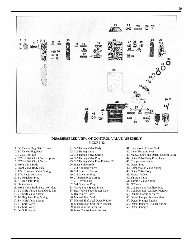
DISASSEMBLED VIEW OF CONTROL VALVE ASSEMBLYFIGURE 42
1. 3-2 Detent Plug Plate Screws 2. 3-2 Detent Plug Plate 3. 3-2 Detent Plug 4. "T" Oil Ball Check Valve Spring 5. "T" Oil Ball Check Valve 6. Front Valve Body 7. Front Valve Body Plate 8. T.V. Regulator Valve Spring 9. T.V. Regulator Valve10. 1-2 Regulator Plug11. 3-4 Regulator Plug12. Shuttle Valve13. Front Valve Body Separator Plate14. 2-3 Shift Valve Spring Guide Pin15. 2-3 Shift Valve Spring16. 1-2 Regulator Plug Spring17. 3-4 Shift Valve Spring18. 2-3 Shift Valve19. 1-2 Shift Valve20. 3-4 Shift Valve
21. 3-2 Timing Valve Body22. 3-2 Timing Valve23. 3-2 Timing Valve Spring24. 3-2 Timing Valve Plug25. 3-2 Timing Valve Plug Retainer Pin26. Inner Valve Body27. 2-3 Auxiliary Valve28. 2-3 Governor Sleeve29. 2-3 Governor Plug30. 2-l Detent Plug Spring31. 2-1 Detent Plug32. 3-4 Governor Plug33. Valve Body Spacer Plate34. Rear Valve Body Spacer Plate35. Rear Valve Body36. Manual Shaft Seal37. Manual Shaft Seal Outer Washer38. Manual Shaft Seal Inner Washer39. Inner Control Lever Pin40. Inner Control Lever Washer
41. Inner Control Lever Seal42. Inner Throttle Lever43. Manual Shaft and Detent Control Lever44. Outer Valve Body Front Plate45. Compensator Valve46. Detent Plug47. Compensator Valve Spring48. Outer Valve Body49. Manual Valve50. Throttle Valve51. Throttle Valve Spring52. "T" Valve53. Compensator Auxiliary Plug54. Compensator Auxiliary Plug Pin55. Double Transition Valve56. Detent Plunger Retainer Plate57. Detent Plunger Retainer58. Detent Plunger Retainer Spring59. Detent Plunger
30
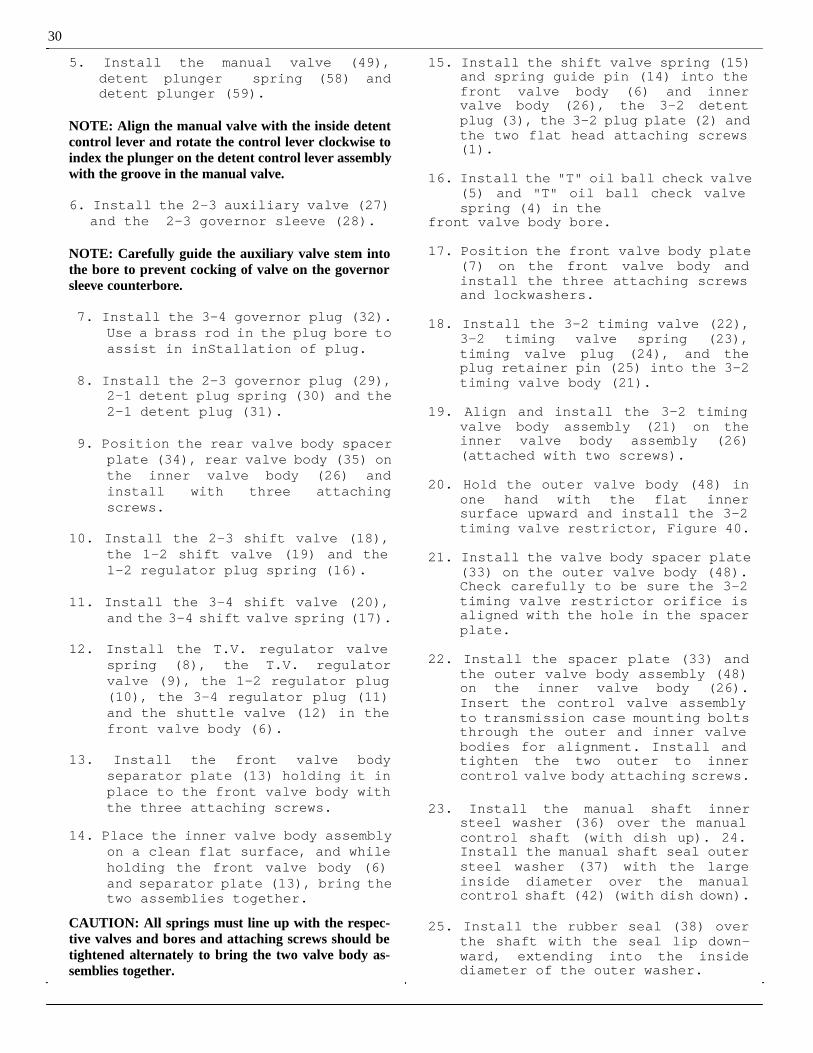
5. Install the manual valve (49), detent plunger spring (58) and detent plunger (59).
NOTE: Align the manual valve with the inside detent control lever and rotate the control lever clockwise to index the plunger on the detent control lever assembly with the groove in the manual valve.
6. Install the 2-3 auxiliary valve (27) and the 2-3 governor sleeve (28).
NOTE: Carefully guide the auxiliary valve stem into the bore to prevent cocking of valve on the governor sleeve counterbore.
7. Install the 3-4 governor plug (32). Use a brass rod in the plug bore to assist in inStallation of plug.
8. Install the 2-3 governor plug (29), 2-1 detent plug spring (30) and the 2-1 detent plug (31).
9. Position the rear valve body spacer plate (34), rear valve body (35) on the inner valve body (26) and install with three attaching screws.
10. Install the 2-3 shift valve (18), the 1-2 shift valve (19) and the 1-2 regulator plug spring (16).
11. Install the 3-4 shift valve (20), and the 3-4 shift valve spring (17).
12. Install the T.V. regulator valve spring (8), the T.V. regulator valve (9), the 1-2 regulator plug (10), the 3-4 regulator plug (11) and the shuttle valve (12) in the front valve body (6).
13. Install the front valve body separator plate (13) holding it in place to the front valve body with the three attaching screws.
14. Place the inner valve body assembly on a clean flat surface, and while holding the front valve body (6) and separator plate (13), bring the two assemblies together.
CAUTION: All springs must line up with the respec-tive valves and bores and attaching screws should be tightened alternately to bring the two valve body as-semblies together.
15. Install the shift valve spring (15) and spring guide pin (14) into the front valve body (6) and inner valve body (26), the 3-2 detent plug (3), the 3-2 plug plate (2) and the two flat head attaching screws (1).
16. Install the "T" oil ball check valve (5) and "T" oil ball check valve spring (4) in the
front valve body bore.
17. Position the front valve body plate (7) on the front valve body and install the three attaching screws and lockwashers.
18. Install the 3-2 timing valve (22), 3-2 timing valve spring (23), timing valve plug (24), and the plug retainer pin (25) into the 3-2 timing valve body (21).
19. Align and install the 3-2 timing valve body assembly (21) on the inner valve body assembly (26) (attached with two screws).
20. Hold the outer valve body (48) in one hand with the flat inner surface upward and install the 3-2 timing valve restrictor, Figure 40.
21. Install the valve body spacer plate (33) on the outer valve body (48). Check carefully to be sure the 3-2 timing valve restrictor orifice is aligned with the hole in the spacer plate.
22. Install the spacer plate (33) and the outer valve body assembly (48) on the inner valve body (26). Insert the control valve assembly to transmission case mounting bolts through the outer and inner valve bodies for alignment. Install and tighten the two outer to inner control valve body attaching screws.
23. Install the manual shaft inner steel washer (36) over the manual control shaft (with dish up). 24. Install the manual shaft seal outer steel washer (37) with the large inside diameter over the manual control shaft (42) (with dish down).
25. Install the rubber seal (38) over the shaft with the seal lip down-ward, extending into the inside diameter of the outer washer.
31

32
DIAGNOSIS ANDTESTING
UPSHIFTS TOO HIGH
B-1 Throttle linkage too short.B-3 Outer throttle lever bent.G-1 Valves sticking in control valve
assembly.G-3 Incorrect control valve assembly.I-1 Valves sticking in governor or
improper valve travel.I-2 Governor oil de livery pipe leaking
at connections.I -3 Incorrect governor installed.
UPSHIFTS TOO LOW
B-2 Throttle linkage too long.B-3 Outer throttle lever bent.G-1 Valves sticking in control valve
assembly.G-2 Internal leak in control valve
assembly possible loose screws or mating surfaces require lapping.
G-3 Incorrect control valve assembly.I -2 Governor oil delivery pipe leaking
at connections.I -3 Incorrect governor installed.
UPSHIFT ROUGH
B-1 Throttle linkage too short.B-2 Throttle linkage too long.B-3 Outer throttle lever bent.C-1 Bands should be adjusted externally
to factory specifications. Occa-sionally a transmission may be encountered that will not take a good external adjustment.
If a transmission with normal pressure shifts roughly after a linkage and external band adjust-ment, the bands should be adjusted internally.
E-1 Check line pressure in all ranges. Watch pressure through complete shift pattern.
G-1 Valves sticking in control valve assembly.
G-2 Internal leak in control valve assembly.
Possib1e loose screws or mating sur- faces require lapping.
SLIPS — LIGHT THROTTLEUPSHIFTS
B-2 Throttle linkage too long.
C-1 Bands should be adjusted externally to factory specifications. Occa-sionally a transmission may be encountered that will not take a good external adjustment.
If a transmission with normal pressure shifts roughly after a linkage and external band adjustment, the bands should be adjusted internally.
SLIPS — HEAVY THROTTLEUPSHIFTS
B -2 Throttle linkage too long.B-3 Outer throttle lever bent.C-1 Bands should be adjusted externally
to factory specifications, occa-sionally a transmission may be encountered that will not take a good external adjustment.
If a transmission with normal pressure shifts roughly after a linkage and external band adjust-ment, the bands should be adjusted internally.
E-1 Check line pressure in all ranges. Watch pressure through complete shift pattern.
G-1 Valves sticking in the control valve assembly.
G-2 Internal leak in control valve assembly-possible loose screws or mating surfaces require lapping.
K-1 Compensator leak in Front Servo, between case and servo, or at rear servo compensator pipe connection. Check for leak with air pressure.
L-1 Compensator passage leak in rear servo. Check with air pressure.
SLIPS — 1-2 MISSES 2nd
L-2 Leak in 1-2 oil passage to exhaust valve in rear servo (1953 Models).
K-4 Leak in front servo release passage. Check with air pressure.S-1 Loose bearing cap bolts in case
allowing leak between oil delivery sleeve and cap. Check for leak at this point by applying air pressure to front and rear clutch apply passages in case after removing valve body. If a leak exists, with cap bolts at recommended torque, dress down cap to provide snugger fit to oil delivery sleeve.
Q-1 In correct number of clutch plates or wrong annular piston in front unit. Also worn or damaged clutch plates.
S-2 Oil passages not drilled or inter-connected in case. Remove valve body and air check all case passages

S-3 Broken ring-oil delivery sleeve.
SLIPS — 2-3
B-2 Throttle linkage too long.C-1 Bands should be adjusted externally
to specifications. Occasionally a transmission may be encountered that will not take a good external adjustment. If a transmission with normal pressure shifts roughly after a linkage and external band adjustment, the bands should be adjusted internally.
E-1 Check line pressure in all ranges. Watch pressure through complete shift pattern.
C-2 Adjust bands by internal method.G-1 Valves sticking in control valve
assembly.G-2 Internal leak in control valve
assembly-possible loose screws or mating surfaces require lapping.
K-1 Compensator leak in front servo, be- tween case and servo, or at rear
servo compensator pipe connection. Check for leak with air pressure.
K-6 4-3 downshift valve stuck in closed position.
L-3 Leak in rear servo release passage. Check release passage with air
pressure with servo mounted on case. Make certain servo applies and releases freely without tendency to stick or chatter.
S-1 Loose bearing cap bolts in case allowing leak between oil delivery sleeve and cap. Check for leak at this point by applying air pressure to front and rear clutch apply passages in case after removing valve body. If a leak exists, with cap bolts at recommended torque, dress down cap to provide snugger fit to oil delivery sleeve.
Q-1 In correct number of clutch plates or wrong annular piston in rear unit. Also worn or damaged clutch plates.
R-2 Rear unit annular piston seals or expanders damaged.
S-2 Oil passages not drilled or inter-connected in case. Remove control valve and air check all case passages.
S-3 Broken ring-oil delivery sleeve.
SLIPS — 3-4
NOTE: See Slips 1-2.
UPSHIFTS TO 4th IN "DR-3"AT LOW SPEEDS
D Shift linkage.G-1 Valves sticking in control valve
assembly.G-4 Passages not machined in control
valve assembly.
UPSHIFTS TO 3rd IN "LO"AT LOW SPEEDS
D Shift linkage.G-1 Valves sticking in control valve
assembly.G-2 Internal leak in control valve
assembly - possible loose screws or mating surfaces require lapping.
ROUGH 3-2 or 3-1 — DOWNSHIFT(Closed Throttle)
A Engine idle.B-1 Throttle linkage too short.C-2 Adjust bands by internal method.L-3 Leak in rear servo release passage. Check release passage with air pres- sure.L-4 Broken or misaligned rear servo
check valve.L-5 Rear servo exhaust valve sticking
open.G-1 Valves sticking in control valve
assembly.G-2 Internal leak in control valve
assembly.
NO 4-3 FORCED DOWNSHIFT
B-2 Throttle linkage too long.B-3 Outer throttle lever bent.G-1 Valves sticking open in control
valve assembly.Q-3 Gear failure locking front unit in
direct drive.
NO 3-2 FORCED DOWNSHIFT
B-2 Throttle linkage too long.B-3 Outer throttle lever bent.G-1 Valves sticking open in control
valve assembly.
SLIPS 4-3 - FORCED DOWNSHIFT
K-3 4-3 downshift valve retainer spring out of place (Models through 1952).
K-4 Leaks between front servo valve body and front servo (1953 Models)
33

34
K-5 Front servo by -pass apply passage not drilled through in servo body (1953 Models).
ROUGH 4-3 FORCED DOWNSHIFT
C-1 Bands should be adjusted externally to factory specifications. Occa-sionally a transmission may be encountered that will not take a good external adjustment.
If a transmission with normal pres-sure shifts roughly after a linkage and external band adjustment, the bands should be adjusted internally.
E-1 Check line pressure in all ranges. Watch pressure through complete shift pattern.
G-1 Valves sticking in control valve assembly.
K-7 4 -3 downshift valve stuck in the open position.
ROUGH DOWNSHIFT AFTERCAR IS STOPPED
B-4 Throttle linkage binding.G-1 Valves sticking in control valve
assembly.S-2 0i1 passages not drilled or inter-
connected in case. Remove control valve assembly and air check all case passages.
NO UPSHIFT ABOVE 1st
G-1 Valves sticking in control valve assembly.
H-1 Oil passage leak in parking brake bracket (possibly missing plug) check with air pressure.
I-1 Valves sticking in governor or improper valve travel.
I-2 Governor oil delivery pipe leaking at connections.
N-1 Steel locating ball missing from bronze rear pump drive gear allowing gear to slip on reverse carrier. Condition may only be apparent when transmission is hot, allowing bronze gear to expand.
S-1 Loose bearing cap bolts in case allowing leak between oil delivery sleeve and cap. Check for leak at this point by applying air pressure to front and rear clutch apply passages in case after removing valve body. If a leak exists, with
cap bolts at recommended torque dress down cap to provide snugger fit to oil delivery sleeve.
MISSES 2nd AND 4th
K-2 Leak in front servo release passage. Check with air pressure.
L-2 Leak in 1-2 oil passage to exhaust in rear servo (1953 Models).
S-1 Loose bearing cap bolts in case allowing leak between oil delivery sleeve and cap.
Check for leak at this point by applying air pressure to front and rear clutch apply passages in case after removing
valve body. If a leak exists, with cap bolt s at recommended torque, dress down cap to provide snugger fit to oil delivery sleeve.
S-2 0il passages not drilled or inter-connected in case. Remove control valve assembly and air check all case passages.
Q-1 Incorrect number of clutch plates or wrong annular piston in front unit. Also worn or damaged clutch plates.
Q-2 Front annular piston seals or expanders damaged.
MISSES 1st AND 3rd
Q-3 Gear set failure locking front unit in direct drive.
NO REVERSE — SLIPS
D Shift linkage.E-2 Check line pressure in reverse.
Excessive pressure loss may be caused by missing or mispositioned pressure regul at or reverse oil pipe, or reverse clutch pipe.
F-1 Pressure loss in reverse may be caused by the reverse booster plug missing or sticking in the pressure regulator assembly.
G-5 Improperly assembled control valve asSembly.
I-4 Internal leak in governor.J Line exhaust valve, sticking or
leaking. The line exhaust valve is located
in the case under the front servo on 1952 models, and in the front servo valve body on 1953 models.
N-2 Leaking reverse piston seals will allow slipping and pressure loss in reverse.
LOCK UP IN REVERSE(Light Throttle or Coast)
D Shift linkage.
35
E-2 Check line pressure in reverse. Excessive pressure loss may be caused by missing or mispositioned pressure regulator reverse oil pipe, or reverse clutch pipe.
L-3 Leak in rear servo release passage.
Check release passage with air pressure with servo mounted on case. Make certain servo applies and releases freely without ten-dency to stick or chatter.
J Line exhaust valve sticking or leaking. The line exhaust valve is located in the case under the front servo on 1952 models and in the front servo valve body on 1953 models.
JUMPS OUT OF REVERSE
D Shift linkage.
SELECTOR LEVER WON'TGO INTO "R"
(Engine Running)
J-1 Valves sticking in governor or improper valve travel.
I-5 Broken governor ring.M-1 Governor drive flange off position
on rear pump mispositioning gover-nor in parking brake bracket.
SELECTOR LEVER WON'TGO INTO "R"
(Engine Off)
H-2 Reverse blocker piston sticking in parking brake bracket.
I-5 Broken governor ring.G-1 Valves sticking in control valve
assembly.M-1 Governor drive flange off position on rear pump mispositioning gover-
nor in parking brake bracket.
INTERMITTENT SLIP INALL RANGES
E-1 Check line pressure in all ranges, watch pressure through complete shift pattern.
F-2 Pressure regulator sticking will cause loss of or extremely high pressures-remove regulator valve and run engine at idle speed not over 30 seconds to flush circuit.
J Line exhaust valve sticking or leaking.
K-3 4-3 downshift valve retainer spring out of place (models through 1952).
P-1 Slide sticking (Vane Type Pump) will cause intermittent low and high pressures or complete loss of pressure.
NO DRIVE.
D Shift linkage.E-1 Check line pressure in all ranges.F-2 Pressure regulator sticking will
cause loss of or extremely high pressures. Remove regulator valve and run engine at idle speed not over 30 seconds to flush circuit.
G-5 Improperly assembled control valve assembly.
S-2 0i1 passages not drilled or inter-connected in case.
J Line exhaust valve sticking or leaking.
P-1 Slide sticking (Vane Type Pump) will cause low and high pressures or com- plete loss of pressure.C-3 A broken front band will cause loss
of drive in all positions except where secon d speed start is normal. A broken rear band will cause loss of drive in all posi-tions except reverse.
NO DRIVE AFTER SHIFTINGFROM "R"
N-3 Reverse c one sticking will result in no forward drive after reverse application.
Free up and burnish in cone by driving as described in the Hydra-Matic Transmission Service Manual.
TRANSMISSION SHIFTS ORHUNTS WITH VEHICLE
NOT MOVING
S-2 Oil passages not drilled or inter-connetted in case. Remove valve body and air check all case passag-es.
CLASHES WHEN SHIFTEDTO "R" (51-53)
A Engine idle.E-1 Check line pressure in all ranges.H-3 Parking pawl actuating crank bent
on parking brake bracket.

36
WILL NOT LOCK IN "R" WITHENGINE OFF (51-53)
H-2 Parking blocker piston stuck.
WILL SHIFT INTO "R" ABOVE12 M.P.H.
H-2 Parking blocker piston stuck.
SLIPS IN "DR-3" WHEN USINGENGINE AS A BRAKE
K-8 Over-run control valve sticking. (1952-1953.)
NO DRIVE WHEN ENGINE ISFIRST STARTED
O-1 Torus check valve sticking or dam-aged.
Check for excessive drain back after engine is shut off.
ROUGH SHIFTING "N" TO "R"
C-2 Band s should be adjusted exter-nally to factory specifications.
L-5 Rear servo check valve misaligned or orifice hole undersize.
L-8 On 19 5 3 models, rear servo exhaust valve sticking closed would retard servo application.
UNABLE TO DRIVE ENGINEBY PUSHING OR TOWING
M-2 Rear pump in-operative.
NOISEN-NOISE C-CAUSE
N- Neutral and all gears whenever engine is running.
C- Front oil pump.
N- Neutral only (disappears when shifted to drive),
C- Rear unit planetary gears.
N- Neutral, 1st and 2nd speeds only.C- Rear unit planetary gears.
N- Neutral, 1st, 3rd and reverse speeds only.C- Front unit planetary gears.
N- Reverse Gear acceleration only.C- Reverse unit planetary gears.
N- Reverse gear deceleration only.C- Reverse unit planetary gears.N- Metallic scraping at front of tramis- sion.C- Excessive end play - torus members.N- Vehicle coasting 20 to 35 M.P.H.
engine not running - selector in neutral.
C- Rear oil pump.
N- Severe intermittent torus cover dampener noise in reverse.
C- Output shaft pinions.N- Noisy pressure regulator valve
(52).C- Early design valve - install rubber cushion.
OIL LEAKS
L-OIL LEAKS C-CAUSE
L- Between flywheel and crankshaft flange.
C- Loose flywheel to crankshaft bolts or insufficient sealer.
L- Torus Cover and Flywheel.C- Flywheel to Torus Cover Seal,
Flywheel sealing area, drain plug or dampener rivets in torus cover.
L- Front of transmission.C- Front Pump Cover or Screws, or frontoil seal.
L- Oil Pan.C- Oil Pan Gasket or Drain Plug.
L- Side Cover.C- Side cover gasket or screws, throt-
tle and manual shaft seals, pressure line plug.
L- Rear of transmission.C- Rear Oil Seal, Rear Bearing Retainer Gasket, Rear Bearing Retainer
Bolts.

37
REFERENCE
Source ofInformation
Date Subject

38
1C - 2C - THROTTLE ARRANGEMENTFIGURE 43

39
LINKAGE ADJUSTMENTSTHROTTLE CONTROL LINKAGE
ADJUSTMENT(Models 1C-2C)
1. Place selector lever in "N" (Neutral) position, with engine at normal operating temperature and transmission warm, adjust the engine idle speed to 490-510 R.P.M.
2. Install gauge pin 1-2544 in lever bellcrank at (E), Figure 43, and adjust the throttle bellcrank shaft operating rod (A) to 2-9/32" mea-sured from centerline of throttle control bellcrank to carburetor rod clevis pin and the top of the machined surface of the cylinder head. After adjustment, lock jam nut securely.
3. With the throttle return spring attached and idle adjustment screw against its stop and the 1-2544 gauge pin still in place in the lower bellcrank, adjust the throttle con-trol bellcrank to carburetor rod (B) until the clevis pin slides freely through the holes in clevis and the hole in the bell- crank. Lock jam nuts.
FIGURE 44
4. Disconnect the transmission throttle rod (G), Figure 44, at the transmis-sion outer lever. Tighten outer throttle lever clamp bolt (F) if necessary. Check position of the outer throttle lever as follows:
(a) Clean the machined surface at back of transmission case and place the throttle lever checking gauge 1-2195 flat against the back surface
of the transmission case with the edge of the checking gauge against the back surface of the transmis-sion case with the edge of the checking gauge against the the transmission side cover, Figure 44. (b) With the transmission outer throttle lever held against its stop (toward rear of transmission), the outer throttle lever hole (lower hole) should be centered on the small diameter of the gauge pin (I) and the in side face of the throttle control lever should just touch the large diameter of the gauge rod. DO NOT FORCE the outer lever against its stop and DO NOT try to bend this lever unless you have the proper bending tool.
a
FIGURE 45
NOTE: If the outer throttle lever lower hole does not center on the checking fixture pin as outlined in para-graph (b), use the throttle Lever Bending Tool J-3310 to bend the throttle lever into proper alignment, em-ploying the bending tool as illustrated in Figure 45, with pins facing outward to bend the throttle lever rearward. To bend the lever forward, reverse t he bending tool (bending tool pins will now face towards transmission).5. With 1-2544 gauge pin still in place
in the lower bellcrank at (E), Figure 43, and the transmission T.V. lever in its furthest back position, adjust length of the transmission throttle rod (C) so that it is 3/32" shorter than the actual distance between the holes. Tighten lock nut securely.
6. Remove gauge pin 1-2544 and adjust length of the accelerator pedal to bellcrank rod (D) to give at full throttle, 1/64" to 1/16" clearance between the accelerator pedal and pedal stop at (G).

THROTTLE CONTROL ARRANGEMENTMODELS 1C - 2C WITH TWIN CARBURETORS
FIGURE 46
THROTTLE CONTROL LINKAGEADJUSTMENT - MODELS 1C-2C
WITH TWIN CARBURETORS
1. Adjust engine idle speed at 490-510 R.P.M. with engine at normal operat-ing temperature, transmission warm and selector lever in the "N" (Neutral) position.
2. In stall upper and lower gauge pins as shown in circles (I) and (J), adjust length of rod (A) so that throttle shaft operating rod trun-nion pin will enter the bellcrank. Lock jam nuts securely.
3. With gauge pins (E) still in place, both carburetors off fast idle (choke open) and with the throttle return springs attached, adjust the two rods marked (B) until the clevis pin slides freely through clevis and
lever. Lock jam nuts securely. Whenever carburetor idle position is re-adjusted, rod lengths must be rechecked as above. The throttle return spring must always be hooked into the clevis as shown and never over the clevis. Using the proper tools, Figure 45, bend the trans-mission lever (H) if necessary to the adjustment shown in Figure 43. With the gauge still in place and transmission lever (H) in its furthest back position, adjust length of rod (C) so that it is 3/32" shorter than the actual distance between the hole in the bellcrank lever and the hole in transmission lever. Lock jam nuts securely.
5. Remove gauge pins and adjust length of rod (D) to give, at full throttle, 1/64" to 1/16" clearance between the accelerator pedal and the pedal stop at (G), Figure 43.
40

41
THROTTLE CONTROL LINKAGE ADJUSTMENT - MODELS 4B, 4C, 5B, 5CFIGURE 47
THROTTLE CONTROL LINKAGEADJUSTMENT
MODELS 4B, 4C, 5B, 5C
1. Hook the throttle return spring in the lower hole of the cross shaft lever for Models 4B, 4C, 5B and 5C with the 262 engine at (A), Figure 47.
2. Adjust the engine idle speed at 490-510 R.P.M. with engine at normal operating temperature, transmission warm and selector lever in "N" (Neutral) position.
3. With the carburetor throttle idle screw against its stop and carbure-tor off fast idle (Model 4B-4C with the 232 engine) adjust the throttle control bellcrank to carburetor rod so that the Gauge Pin J-2544 will freely enter the gauge pin holes in the throttle control bellcrank and the slotted hole in the throttle control bellcrank support bracket at (B). After making adjustment, remove gauge pin.
4. On Models 4B, 4C, 5B, 5C, with 262 Engine, with the carburetor idle adjustment screw against its stop, adjust the throttle bellcrank shaft operating rod (this is the cross shaft operating rod for Models 4B, 4C, 5B, 5C with the 262 engine) until the gauge pin will freely enter the seat in the accelerator pedal link bellcrank lever and the gauge hole in the cylinder block at (C), Figure 47, (Located at the end of the starting motor.)
NOTE: Gauge pin J-2544 should work freely in the throttle control bellcrank and gauge hole in block.
5. Check the position of the outer throttle lever as follows:
(a) Clean the machined surface at back of transmission case and place the throttle lever checking gauge J-2195 flat against the back surface of the transmission case with the edge of the checking gauge against the transmission side cover, Figure 44.

(b) With the transmission outer throttle lever held against its stop toward rear of the transmission, the outer throttle hole should be cen-tered on the small diameter of the gauge pin and the inside face of the throttle control lever should just touch the larger diameter of the gauge rod. DO NOT FORCE THE outer lever against its stop and DO NOT try to bend this lever unless you have the proper bending tool, Figure 45.
NOTE: If the outer lever lower hole does not center on the checking fixture pin as outlined in paragraph (B) use the Throttle Lever Bending Tool J-3310 to bend the throttle into proper alignment, employing the bending tool, Fig- u r e 45. To bend lever rearward, have the pins facing outward. To bend the lever forward, re-verse the bending tool, pins will now face toward trans-mission. After properly aligning the throttle checking fixture, install t he transmission throttle rod (G) clevis pin and cotter pin to the outer throttle lever, (H) and secure the cotter pin.
6. For Models 4A, 4B, 4C, 5B, and 5C with the gauge pin, 1-2544, in position at (C), Figure 47 in the throttle control bellcrank and the hole in the cylinder block, disconn e c t the transmission throttle rod at the accelerator pedal link bell-crank lever at (D). Lightly push the transmission throttle valve lever (H) rearward against its stop in the transmission, and adjust the throt-tle rod s o that the trunnion pin will slide freely into the accelera-tor pedal link bell- crank lever. Install the trunnion pin, flat washer and cotter pin. With the trunnion pin in position, loosen the rear adjusting nut (E) approximately one and three quarter turns or until a 1/16" shim can be installed between the rear lock nut and the trunnion: remove the shim and tighten the front lock nut (F) without turning the rear lock nut, (E). This will pull the throttle lever forward off the stop. Remove gauge pin.
THROTTLE CONTROLADJUSTMENTS
4B-5B-4B-5C with 262 EngineWITH TWIN CARBURETORS
1. Insert Gauge Pin J-2544 through accelerator pedal link bellcrank
lever at (E), Figure 48, and into hole into the cylinder block. Adjust length of throttle shaft operating r o d assembly to position throttle shaft lever as shown at CC.2. With gauge pin still in position and both carburetors off fast idle (choke open) and with throttle return springs attached, adjust length of each rod assembly (B) until the c le vi s pin (K) slides freely through clevis and bellcrank lever. Lock jam nut securely.
NOTE: When carburetor idle position is readjusted, rod length must be rechecked as above.
3. Using the proper tools, Figure 45, bend the transmission lever (if necessary) to the dimension shown, Figure 48. With gauge pin still in position and transmission lever in its furthest back position, adjust transmission throttle rod (C) length so that it is 1/16" shorter than the actual distance bet we e n the trunnion (L) and the clevis pin (M) centers. Lock trunnion jam nuts. Rem ove gauge pin and adjust length of accelerator pedal to bellcrank rod assembly (D) Figure 48, to give at full throttle 1/64" to 1/16" clear-ance between the accelerator pedal and the pedal stop at (G).
THROTTLE CONTROL LINKAGEADJUSTMENT
MODELS 6B-7B & 7C1. Adjust engine idle at 490-510 R.P.M.
with engine at normal operating temperature, transmission warm and selector lever in "N" (Neutral) position.
2. With the carburetor throttle idle screw again st its stop and carbure-tor off fast idle , adjust the accelerator cross shaft, operating rod trunnion nuts (B), Figure 49, until gauge pin 1-2544 can be in-stalled freely into the accelerator pedal bellcrank lever (C) Figure 50, and the hole in the boss of the cylinder block at (D). Tighten the trunnion lock nuts (B) securely. Recheck this adjustment by removing and insta11ing the gauge pin into the bellcrank lever and boss hole. Pin should again enter both holes freely. After rechecking this adjustment, remove the gauge pin.
42

43
THROTTLE CONTROL ARRANGEMENT4C-5C WITH 262 ENGINE WITH TWIN CARBURETORS
FIGURE 48

3. Raise the car, disconnect the transmission throttle rod (G). Figure 44, at the transmission outer lever (H)
by removing the cotter pin and clevis pin. Tighten outer throttle lever clamp bolt (F), Figure 44, if neces-sary.
4. Check position of the outer throttle lever as follows:
(a) Clean the machined surface at back of transmission case and place the Throttle Lever Checking Gauge J-2195 flat against the back surface of the transmission case with the edge of the checking gauge against the transmission side cover, Figure 44.
(b) With the transmission outer throttle lever held against its stop (toward rear of transmission), the outer throttle lever hole should be centered on the small diameter of the gauge pin (1) and the inside face of the throttle control lever should just touch the larger diameter of the gauge rod. DO NOT FO RC E the outer lever against its stop and DO NOT try to bend this lever unless you have the proper bending tool.
NOTE: If the outer throttle lever lower hole does not center on the checking fixture pin as outlined in paragraph (b) use the Throttle Lever Bending Tool J-3310 to bend the throttle lever into proper alignment, employing the bend-ing tool as illustrated in Figure 45, with pins facing outward to bend the lever rearward. To bend the lever forward, reverse the bending tool (bending tool pins will now face toward transmission).
(c) After properly aligning the throttle outer lever to the throttle checking fixture, install the trans-mission throttle rod (G), clevis p in , and cotter pin to the outer throttle lever (H), secure the cotter pin; lower car.
5. Disconnect the transmission throttle rod trunnion (I) from the accelera-tor pedal link bellcrank lever by removing the cotter pin and flat washer from the trunnion pin, Figure 51. Install Gauge Pin J-2544 into accelerator bellcrank lever (C) and hole in boss.
44
CARBURETOR THROTTLE ADJUSTMENTFIGURE 49
CHECKING THROTTLE LEVERFIGURE 50

THROTTLE ROD ADJUSTMENTAT BELLCRANK
FIGURE 51
6. Holding the transmission throttle lever against its stop in t he transmission by pushing the transmission throttle rod (G) rearward lightly by hand, Figure 52, adjust the transmission throttle rod so trunnion pin will slide freely into the accelerator pedal link bellcrank lever (L).
TIGHTING THROTTLE ROD LOCK NUTFIGURE 52
7. Install the trunnion pin, flat washer and cotter pin and with the trunnion pin in position loosen the rear adjusting nut (E) approxi-mately 1-3/4 turns or until a 1/16" shim can be installed between the rear lock nut and the trunnion; remove the shim and tighten the front lock nut (F) without turning the rear lock nut, (E). This will pull the throttle lever forward of the stop a distance equivalent to the thickness of the shim (1/16"). Remove gauge pin J-2544.
8. Loosen lock Nut (N).
9. While holding the carburetor throt-tle wide open and with the acceler-ator pedal against its stop at the floor panel (driver's compartment), adjust lock nut (N) until it touches the trunnion; increase adjustment 1/4" further and tighten front lock nut. This will give approximately 1/16" clearance between bottom of accelerator and the stop.
THROTTLE CONTROLARRANGEMENT
6B, 7B and 7C with Twin Carburetors
1. Insert gauge pin J-2544 (E) in accelerator pedal link b ellc rank assembly with the choke valve held open to keep carburetor off fast idle setting, push carburetors closed. Now adjust length of carbu-retor rods (B), Figure 53, so that the clevis pins can be entered and withdrawn freely. When carburetor idle position is readjusted, rod length must be rechecked as above. Throttle control return spring (F) must be in place during adjustments.
2. Adjust length of rod (D) so that it is 1/16" shorter than the actual distance between trunnion (L) and clevis pin (M) centers. When the gauge pin is in place and the throttle control lever (H) on trans-mission is at its furthest back position.
3. After the carburetor to throttle shaft rods (B) and transmission throttle rod (D) are adjusted remove the gauge pin and adjust the pedal rod (C) to give 1/64" to 1/16" pedal stop clearance shown at (G) at full open throttle.
45

46
THROTTLE CONTROL ARRANGEMENT6B, 7B & 7C WITH TWIN CARBURETORS
FIGURE 53

MANUAL CONTROLLINKAGE ADJUSTMENT
1C, 2C, 4B, 4C, 5B, 5C, 6B, 7B and 7C
1. After determining that the upper and lower control tube brackets are tightened securely on the steering column jacket tube and that the selector lever tube is parallel with the steering gear jacket tube, disconnect the transmission shift rod (0) as shown in Figure 54, at the manual control lower lever, (P).
2. With the transmission shift rod (0) disconnected, place transmission shift lever (Q) (at transmission) in the reverse position by pushing the transmission shift rod (0) rearward as far as it will go (reverse position). Next pull lever rod (0) forward two detents to the "DR-3" position.
3. Place the manual selector lever (at steering wheel) in the "DR-3" posi-tion and pull the manual selector lever against the stop without lifting the selector lever.
4. Adjust rod length to allow clevis pin to enter yoke (0) freely.
5. Lengthen rod by one complete turn of yoke (0).
6. In stall clevis pin, flat washer and cotter pin and tighten lock nut securely.
NEUTRAL SAFETY SWITCHADJUSTMENT
1. Place the manual control lever in the "N" (Neutral) position.
2. Loosen the safety switch adjusting screw (S), Figure 55, and adjust the switch to close at a position approximately midway between "N" (Neutral) and "DR-4" (Drive) on the selector indicator dial. Tighten adjusting screw securely.
NOTE: With the manual lever in the "N" (Neutral) position, the starter should operate when the ignition switch is on and starter is engaged. The s tarter should not operate in any other position but "N" (Neutral).
PUSHING SHIFT ROD TO REVERSEFIGURE 54
SAFETY SWITCH ADJUSTMENTFIGURE 55
47

48
T O R Q U E C H A R T1 C , 2 C , 4 B , 4 C , 5 B , 6 B , 7 B , 7 C
LOCATION THREAD SIZE TORQUE FT. LBS.
Internal Gear to Rear Drum Front Body to Inner Body Outer to Inner Valve Body Rear Cover to Inner Body Front Body Plate to Body Front Plate to Outer Body Governor Bushing Retainer to Governor Body Detent Ball Retainer to Outer Valve Body Front Servo Assembly Torus Cover Drain Case Oil Pressure Take-Off Front Servo Assembly Front Pump Cover to Body Intake Pipe to Front Pump Governor Body to Dual Flange Rear Pump Cover to Body Rear Pump Cover to Body Control Valve Assembly to Case Side Cover to Case Servo Body to Cylinder Blocker Piston Retracting Spring to Bracket Governor Plunger to Governor Primary and Secondary Weights Oil Pan to Case Front Pump Cover to Case Drive Flange to Rear Drum Servo Spring Retainer to Body Reverse Shifter Bracket to Case Rear Pump to Case -Outer Shift Lever Front Servo to Case Rear Servo to Case Reverse Internal Gear Support to Rear Bearing Retainer Rear Bearing Retainer to Case Center Bearing Cap to Case Reverse Anchor Support Bolt Reverse Anchor Support Stud Reverse Anchor Support Stud Nut Band Anchor Stop Nut Oil Pan Drain Screw Pressure Regulator Valve Plug Flywheel Housing to Engine Rear Mounting Bolt Engine Rear Mounting to Frame Bolt Outer Throttle Lever Bolt Torus Check Valve Retainer Bolt Trans. Mainshaft Nut Flywheel to Crankshaft Nut *Torus Cover to Flywheel Bolt
* Procedure for Tightening
Tighten 2 bolts adjacent to dowels to Tighten 2 bolts located 90 deg. from dowels to Tighten all bolts in rotation to Tighten all bolts in rotation to
10-2410-2410-2410-2410-2410-2410-2410-241/8 Pipe1/8 Pipe1/8 Pipe1/4 Pipe1/4-201/4-201/4-201/4-201/4-201/4-201/4-201/4-201/4-201/4-285/16-185/16-185/16-185/16-185/16-185/16-185/16-243/8-163/8-163/8-163/8-167/16-147/16-207/16-207/16-201/2-205/8-181-1/16-167/16-147/16-201/4-281/4-287/8-163/8-245/16-24
12-15 Ft. Lbs.12-15 Ft. Lbs.20-25 Ft. Lbs.26-31 Ft. Lbs.
3-43-43-43-43-43-43-43-46-76-715-186-712-1510-126-86-88-106-810-126-86-86-810-1310-13 10-1310-1315-1815-1810-1323-2823-2828-3328-3340-5023-2815-2023-2840-5035-45•40-5040-5040-4510-156-850-6040-45
