19 electromagnetic induction
DESCRIPTION
Presentation Slides for Combined Science 5129 Physics Topic 'Electromagnetic Induction'.Created for 'Bengkel Kecemerlangan Akademik 2015'TRANSCRIPT
“ELECTROMAGNETIC INDUCTION”
PRINCIPLES OF ELECTROMAGNETIC INDUCTIONTHE A.C GENERATORTHE TRANSFORMER
Combined Science 5129BENGKEL KECEMERLANGAN AKADEMIK 2015

LEARNING OUTCOMES

ELECTROMAGNETIC INDUCTION“Production of electricity from magnetism”
This phenomena led to the construction of generators for producing electrical energy in power station.
ELECTROMAGNETICINDUCTION
MUTUALINDUCTION
Induced e.m.f & induced current created due to:- wire moving through a
magnetic field- magnet moving through a
coil
Movement is observable.
Induced e.m.f & induced current created due to:
- changing (growing/shrinking)magnetic field lines
of a coil is cut by another nearby coil.
No observable movement.
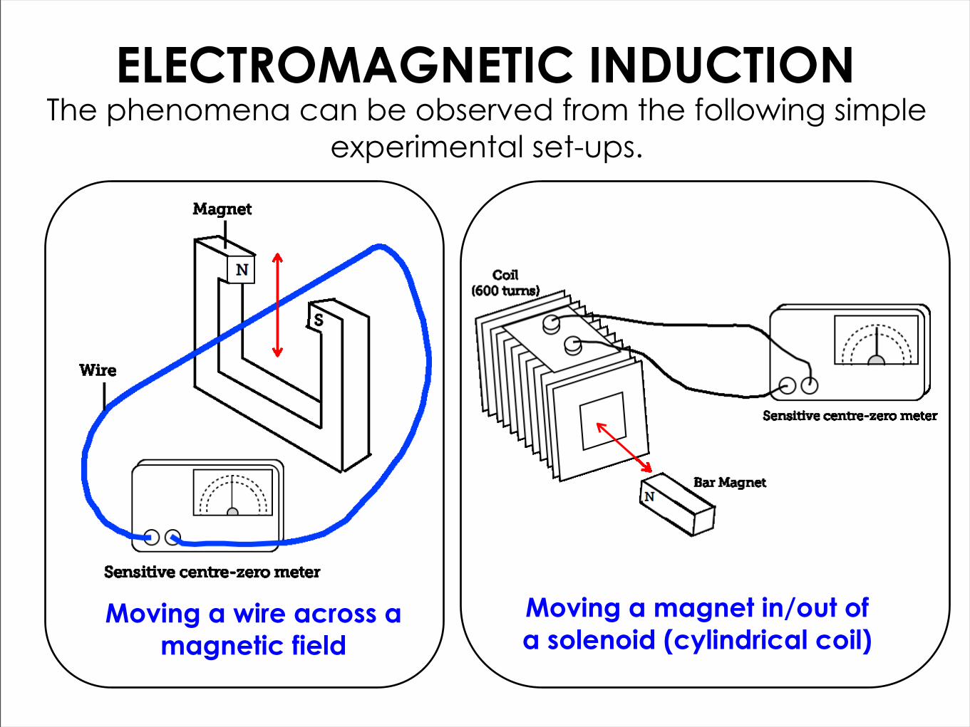
ELECTROMAGNETIC INDUCTION
Moving a wire across a magnetic field
The phenomena can be observed from the following simple experimental set-ups.
Moving a magnet in/out of a solenoid (cylindrical coil)

ELECTROMAGNETIC INDUCTION
Moving a wire across a magnetic field
In both set-up, current is detected by the ammeter (needle will deflect) only when the wire/magnet is moved in the direction stated in
the diagram.
Moving a magnet in/out of a solenoid (cylindrical coil)
No current is detected by the ammeter (no needle deflection)
when the wire/magnet not moving.

MECHANISM OF EM INDUCTIONMoving A Wire Across A Magnetic Field
Whenever magnetic field lines are cut by a conductor (wire/
coil), e.m.f is induced in the conductor.
If the conductor is part of a closed circuit, induced current
will flow in the circuit.
In the direction shown, the wire is moving perpendicularly across the
magnetic field lines.Magnetic lines are ‘cut’ by the wire.
N S
Direction of motion
of wire
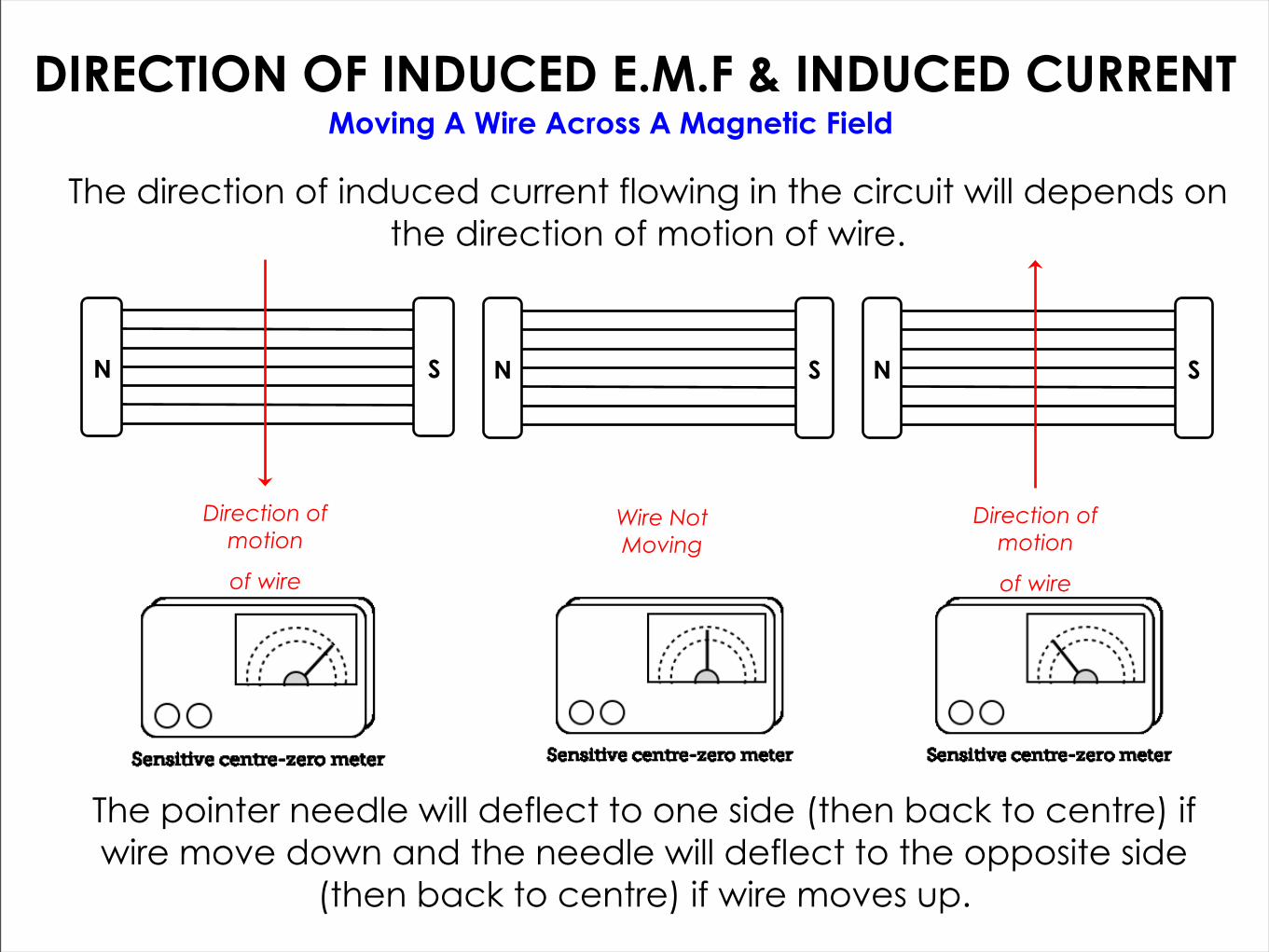
DIRECTION OF INDUCED E.M.F & INDUCED CURRENTMoving A Wire Across A Magnetic Field
The pointer needle will deflect to one side (then back to centre) if wire move down and the needle will deflect to the opposite side
(then back to centre) if wire moves up.
The direction of induced current flowing in the circuit will depends on the direction of motion of wire.
N S
Direction of motion
of wire
N S
Direction of motion
of wire
N S
Wire Not Moving

Moving A Wire Across A Magnetic Field
The pointer needle will deflect to one side (then back to centre) and if the magnetic field is reversed, the needle will deflect to the
opposite side (then back to centre).
The direction of induced current flowing in the circuit will also depends on the direction of the magnetic field.
N S
Direction of motion
of wire
S N
Direction of motion
of wire
DIRECTION OF INDUCED E.M.F & INDUCED CURRENT

PREDICTING THE DIRECTION OF INDUCED E.M.F & INDUCED CURRENT
Moving A Wire Across A Magnetic Field
For a straight wire, the direction of induced current flowing in the circuit can be predicted using Fleming’s Right Hand Rule.
FLEMING’S RIGHT HAND RULE
Motion
Magnetic Field
Induced Current

MECHANISM OF EM INDUCTIONMoving A Magnet In/Out of A Solenoid (Coil)
In the direction shown, the magnet is moving
perpendicularly through the coil.Its magnetic lines are ‘cut’ by
the coil .
Whenever magnetic field lines are cut by a conductor (wire/
coil), e.m.f is induced in the conductor.
If the conductor is part of a closed circuit, induced current
will flow in the circuit.
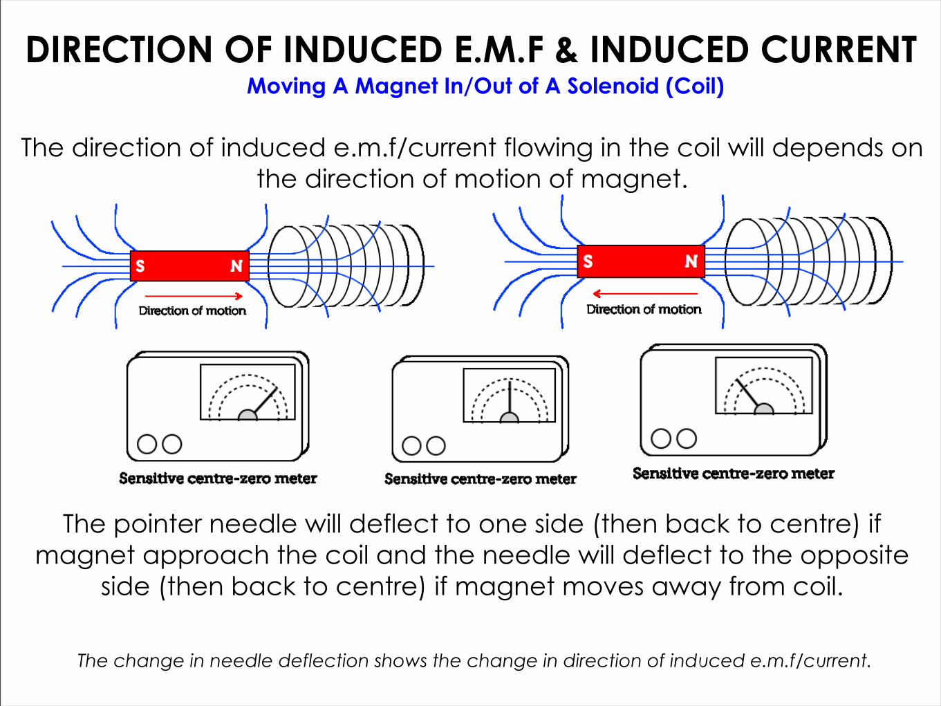
DIRECTION OF INDUCED E.M.F & INDUCED CURRENTMoving A Magnet In/Out of A Solenoid (Coil)
The direction of induced e.m.f/current flowing in the coil will depends on the direction of motion of magnet.
The pointer needle will deflect to one side (then back to centre) if magnet approach the coil and the needle will deflect to the opposite
side (then back to centre) if magnet moves away from coil.
The change in needle deflection shows the change in direction of induced e.m.f/current.

DIRECTION OF INDUCED E.M.F & INDUCED CURRENTMoving A Magnet In/Out of A Solenoid (Coil)
The direction of induced e.m.f/current flowing in the coil will also depends on the incoming magnetic pole.
The pointer needle will deflect to one side (then back to centre) if N-pole approach the coil and the needle will deflect to the
opposite side (then back to centre) if S-pole approach the coil.
The change in needle deflection shows the change in direction of induced e.m.f/current.
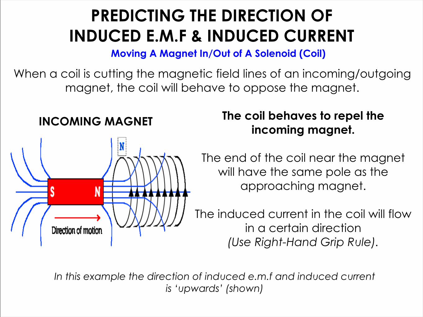
PREDICTING THE DIRECTION OF INDUCED E.M.F & INDUCED CURRENT
Moving A Magnet In/Out of A Solenoid (Coil)
When a coil is cutting the magnetic field lines of an incoming/outgoing magnet, the coil will behave to oppose the magnet.
INCOMING MAGNET The coil behaves to repel the incoming magnet.
The end of the coil near the magnet will have the same pole as the
approaching magnet.
The induced current in the coil will flow in a certain direction
(Use Right-Hand Grip Rule).
In this example the direction of induced e.m.f and induced current is ‘upwards’ (shown)

PREDICTING THE DIRECTION OF INDUCED E.M.F & INDUCED CURRENT
Moving A Magnet In/Out of A Solenoid (Coil)
When a coil is cutting the magnetic field lines of an incoming/outgoing magnet, the coil will behave to oppose the magnet.
OUTGOING MAGNET The coil behaves to attract the outgoing magnet.
The end of the coil near the magnet will have the opposite pole as the
outgoing magnet.
The induced current in the coil will flow in the opposite direction.
(Use Right-Hand Grip Rule).
In this example the direction of induced e.m.f and induced current is ‘downwards’ (shown)
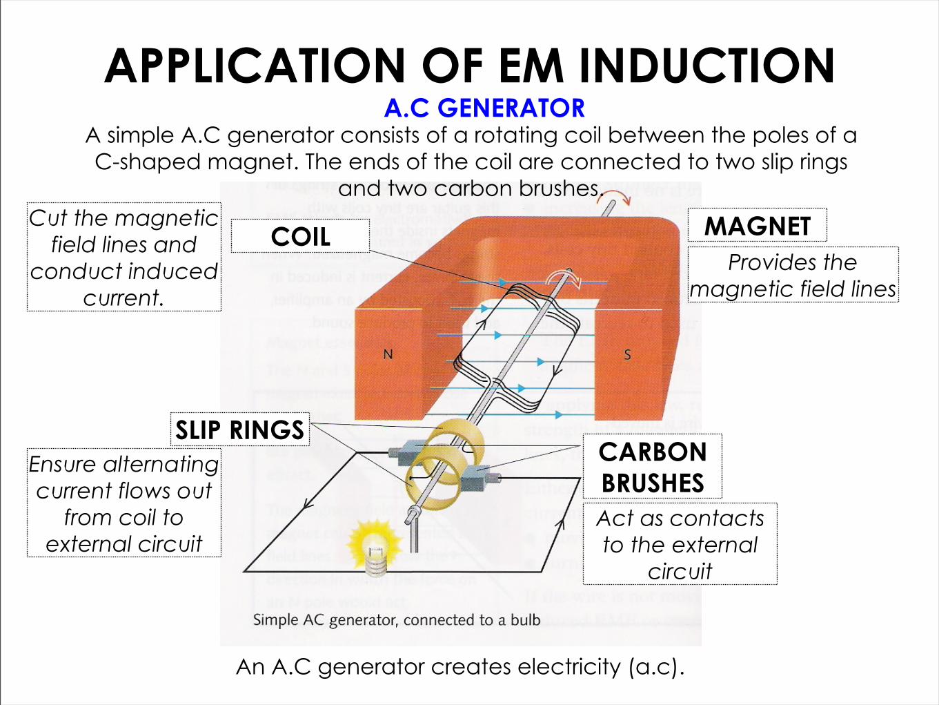
MAGNETCOIL
SLIP RINGSCARBON BRUSHES
Cut the magnetic field lines and
conduct induced current.
Provides the magnetic field lines
Act as contacts to the external
circuit
Ensure alternating current flows out
from coil to external circuit
APPLICATION OF EM INDUCTIONA.C GENERATOR
A simple A.C generator consists of a rotating coil between the poles of a C-shaped magnet. The ends of the coil are connected to two slip rings
and two carbon brushes.
An A.C generator creates electricity (a.c).
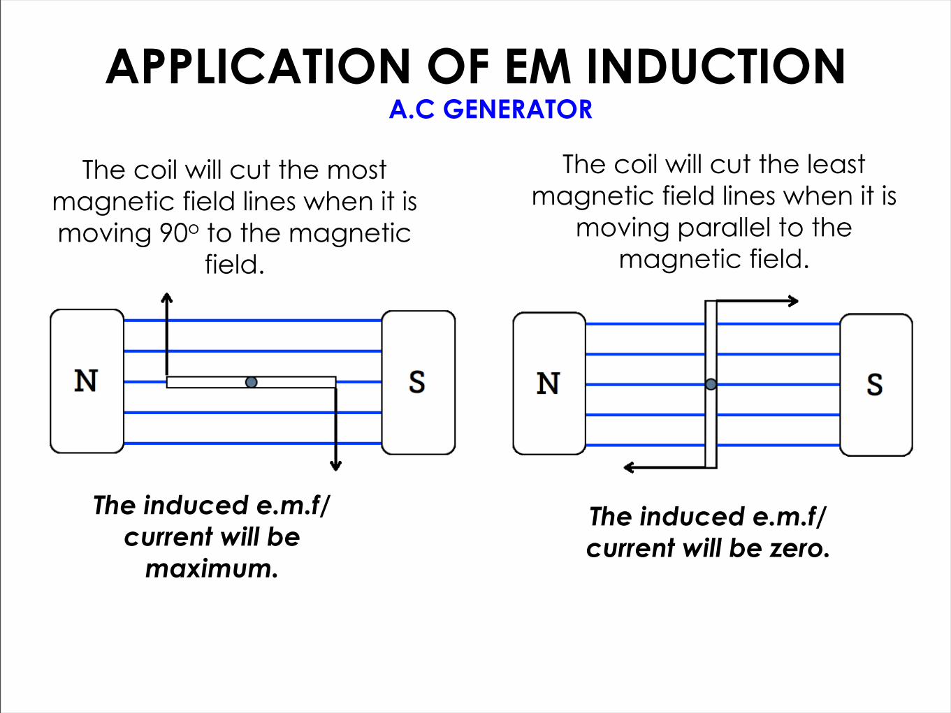
APPLICATION OF EM INDUCTIONA.C GENERATOR
The coil will cut the most magnetic field lines when it is moving 90o to the magnetic
field.
The induced e.m.f/current will be
maximum.
The induced e.m.f/current will be zero.
The coil will cut the least magnetic field lines when it is
moving parallel to the magnetic field.
APPLICATION OF EM INDUCTIONA.C GENERATOR
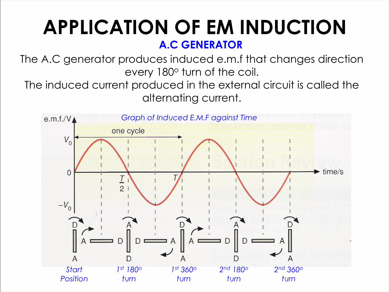
The A.C generator produces induced e.m.f that changes direction every 180o turn of the coil.
The induced current produced in the external circuit is called the alternating current.
Graph of Induced E.M.F against Time
1st 180o turn
1st 360o turn
2nd 180o turn
2nd 360o turn
Start Position

STRENGTH OF INDUCED EMF
The size of induced e.m.f and induced current depends on the following factors:
STRENGTH OF MAGNET
SPEED OF MOTION OF MAGNET OR COIL
Stronger Magnet, Larger induced E.M.F &
induced Current
Faster Movement, Larger induced E.M.F &
induced Current
NUMBER OF TURNS IN THE COIL
More number of turns in coil,
Larger induced E.M.F & induced Current

MUTUAL INDUCTION“A changing magnetic field in a primary coil induces
an e.m.f and current in a nearby secondary coil.”
A changing magnetic field - growing/shrinking magnetic field or the magnetic field changes direction
The size of induced e.m.f & current can be increased by increasing the no. of turns in the secondary coil and by wounding the coils around a soft iron ring.

APPLICATION OF MUTUAL INDUCTIONTHE TRANSFORMER
A transformer changes an alternating voltage from one value to another of greater or smaller value.
A transformer consists of a primary coil and secondary coil wound on a complete soft iron core.

APPLICATION OF MUTUAL INDUCTIONTHE TRANSFORMER
A transformer is 100% efficient.Power Input in Primary Coil = Power Output in Secondary Coil
IP VP = IS VS
STEP UP TRANSFORMER STEP DOWN TRANSFORMER
Has more no. of turns in primary coil.
NP > NS
Has more no. of turns in secondary coil.
NS > NP
Secondary voltage larger than primary voltage
VS > VP
Secondary voltage smaller than primary voltage
VP > VS

APPLICATION OF MUTUAL INDUCTIONTHE TRANSFORMER
An alternating current (a.c) changes direction every cycle.
The alternating current supply in the primary coil creates a continually changing magnetic field inside the soft iron core.
This changing magnetic field lines are cut by the secondary coil, inducing e.m.f and current continuously in the output circuit.
INITIAL CYCLE ONE CYCLE LATER

APPLICATION OF MUTUAL INDUCTIONTHE TRANSFORMER
A direct current (d.c) supply provides current that flows in one direction only.
The d.c supply in the primary coil creates a stable magnetic field inside the soft iron core.
At the initial switch on, the growing magnetic field lines are cut by the secondary coil, inducing e.m.f and current in the output circuit.
When the magnetic field is stable, no magnetic field lines are cut, no e.m.f and current is induced in the secondary coil.
INITIAL LATER

EXAMPLE EXERCISE 1Fig. 16.1 shows a bar magnet being pushed into a coil of wire.
The ammeter shows that there is a small current in the coil.
5129/22/O/N/11 Q16
(a) Name this electrical effect.
(b) State two factors affecting the size of the current when a magnet is pushed into a coil.
(c) The current in the coil produces a magnetic field. What effect does this magnetic field have on the bar magnet.

EXAMPLE EXERCISE 2Fig. 17.1 shows a magnet being pushed towards a coil to induce
an e.m.f. A current is induced in the coil.
5129/22/M/J/13 Q17
Explain how the induced current produces effects that oppose the motion of the magnet.

EXAMPLE EXERCISE 3
A wire is moved downwards between the North and South poles of two magnets, as shown in Fig.9.1
5129/02/O/N/09 Q9
The variation of induced e.m.f with time is shown in Fig.9.2

EXAMPLE EXERCISE 3
(a) Use Fig.9.2 to state at which time: (i) the induced e.m.f is at maximum (ii) the wire is not moving
5129/02/O/N/09 Q9
(b) Name two factors affecting the magnitude of the induced e.m.f.
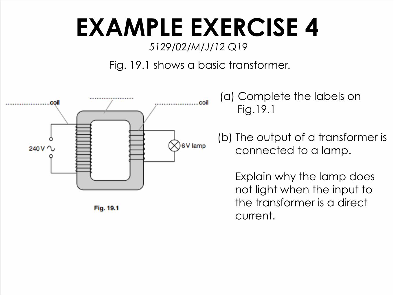
EXAMPLE EXERCISE 4Fig. 19.1 shows a basic transformer.
5129/02/M/J/12 Q19
(a) Complete the labels on Fig.19.1
(b) The output of a transformer is connected to a lamp. Explain why the lamp does not light when the input to the transformer is a direct current.
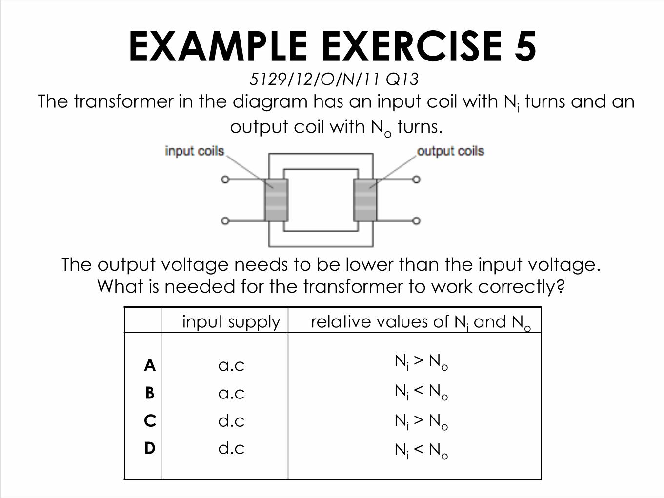
EXAMPLE EXERCISE 5The transformer in the diagram has an input coil with Ni turns and an
output coil with No turns.
5129/12/O/N/11 Q13
The output voltage needs to be lower than the input voltage.What is needed for the transformer to work correctly?
input supply relative values of Ni and No
A
B
C
D
a.c
a.c
d.c
d.c
Ni > No
Ni < No
Ni > No
Ni < No

EXAMPLE EXERCISE 6Which transformer arrangement produces an output voltage
that is larger than the input voltage?
5129/12/O/N/13 Q38

PRACTISE QUESTION
5129/22/O/N/14 Q17
Complete the following questions in pairs.
Remember to raise your hands if you need help with the question.