1875 dewey avenue benton harbor, mi 49022 phone 269 … · mepco reserves the right to make...
TRANSCRIPT

FORM 3618C 2009PRINTED IN U.S.A.
1875 Dewey Avenue Benton Harbor, MI 49022 Phone 269-925-2522 Fax 269-925-7888
MEPCO reserves the right to make revisions to its products, their specifications, this file sheet and related information without notice.
SMV3618C®
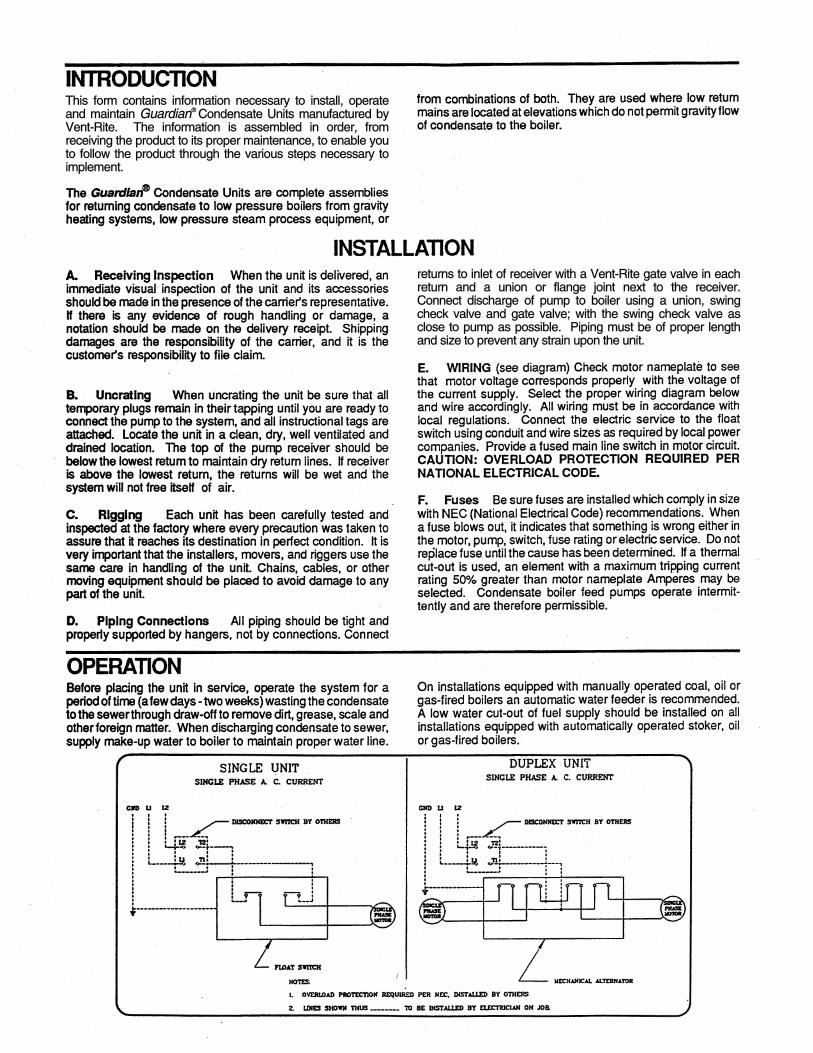
This form contains information necessary to install, operate and maintain Guardian® Condensate Units manufactured by Vent-Rite. The information is assembled in order, from receiving the product to its proper maintenance, to enable you to follow the product through the various steps necessary to implement.
returns to inlet of receiver with a Vent-Rite gate valve in each return and a union or flange joint next to the receiver. Connect discharge of pump to boiler using a union, swing check valve and gate valve; with the swing check valve as close to pump as possible. Piping must be of proper length and size to prevent any strain upon the unit.
For Trial Operation Of Unit, Proceed As Follows:
- 1) Shut power off to unit. 2) Remove plug on rear of motor and with large bladed screwdriver rotate shaft to be sure pump is free. 3) Fill the receiver tank with enough water to close the float switch. ·
- 4) Open gate valve. - 5) Do not o~erate pump without water in the receiv-
ing tank as t e pump is equipped with a mechanical shaft seal. Operating the pump dry may ruin seal.
- 6) The pump will discharge water from the receiving tank into the boiler stopping automatically when water in receiving tank reaches a low level.
OPERA TING POINTS
- 1) Check motor speed. If motor speed is low check wiring connections to motor. If wired for 230 volt current, but actually operating on 115 volt current, the
motor will never come up to proper speed, and motor may bum out.
- 2) Lack of capacity may indicate that passageways of pump impeller have become clogged with foreign matter.
- 3) If the pump fails to start, it may be due to the float ball having lost its buoyancy. This can be checked by operating the float head lever manually . .If the float ball is not buoyant, replace with new float ball. 4) If after long service, water flows from around the motor shaft out through the space between the pump head motor flange and the pump head case flange, it is an indication of a mechanical seal failure and the complete mechanical shaft seal should be replaced. Motor(s) not provided with grease fittings have bearings greased for life by motor manufacturer.
- PARTS- When ordering parts, give type, size and serial number shown on the pump nameplate.
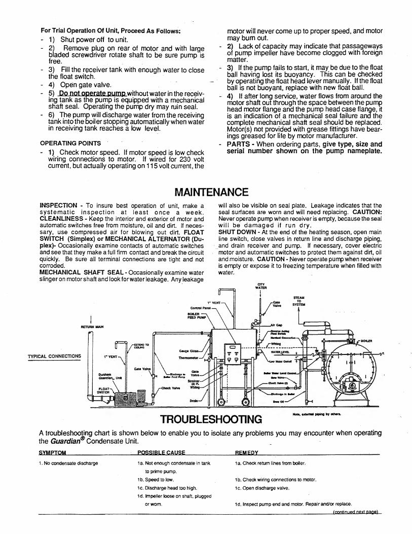
MAINTENANCE INSPECTION • To insure best operation of unit, make a systematic inspection at least once a week. CLEANLINESS - Keep the interior and exterior of motor and automatic switches free from moisture, oil and dirt. If necessary, use compressed air for blowing out dirt. FLOAT SWITCH (Simplex) or MECHANICAL AL TERNA TOR (Duplex)- Occasionally examine contacts of automatic switches and see that they make a full firm contact and break the circuit quickly. Be sure all terminal connections are tight and not corroded. MECHANICAL SHAFT SEAL - Occasionally examine water slinger on motor shaft and look for water leakage. Any leakage
RE'IVRHMAIH
TYPICAL CONNECTIONS
will also be visible on seal plate. Leakage indicates that the seal surfaces are worn and will need replacing. CAUTION: Never operate pump when receiver is empty, because the seal will be damaged if run dry. SHUT DOWN - At the end of the heating season, open main line switch, close valves in return line and discharge piping, and drain receiver and pump. If necessary, cover electric motor and automatic switches to protect them against dirt, oil and moisture. CAUTION - Never operate pump when receiver is empty or expose it to freezing temperature when filled with water.
CIT"( WA11'11
l S1EAll TO
SYSTEM
TROUBLESHOOTING A troubleshooting chart is shown below to enable you to isolate any problems you may encounter when operating the Guardian® Condensate Unit.
SYMPTOM
1. No condensate discharge
PQSS!BLE CAUSE
1 a. Not enough condensate in tank
to prime pump.
1b. Speed to low.
1c. Discharge head too high.
1d. Impeller loose on shaft, plugged
orwom.
REMEQY
1a Check return lines from boiler.
1b. Check wiring connections to motor.
1 c. Open discharge valve.
1d. Inspect pump end and motor. Repair and/or replace.
(continued next page)
2. lnsutndent condensate dlscharge 2a. Air or water leak.
2b. Plugged pump vent Hne.
2c. Speed too low.
2a. Check bleeder line.
2b. Disconnect vent line from Guradlan Pump - Reconnect.
2c. Check motor wiring.
2d. Impeller loose on shaft. plugged or wom. 2d. Replace Impeller. Check with manufacturer.
3. Pump does not start
4. Excessive power consumption
3a. Motor lead connections may be
wired wrong.
3b. Blown fuses In disconnect switch.
3c. Loose connection.
3d. Rotating assembly Is bound.
4a. Speed too high.
4b. Loose wiring connections.
4c. Mechn'I defects: (1) Motor shaft bent
(2) Rotating element binds
(3) Foreign elements between
Impeller and wearing ring.
3a. Check wiring diagram, page 2.
3b. Check fuses.
3c. Check wiring.
3d. Try turning motor shaft from top side of motor with screwdriver
or open wrench.
4a. Check voltage
4b. Check wiring connections.
4c. (1) Replace motor.
4c. (2) Reassemble & tighten parts.
4c. (3) Disassemble & check condition.
5. Pump Is noisy Sa. Bearings bad (sealed bearings in motor) Sa. Check with motor manufacturer. ·
Sb. Pump may be operating at a low enough Sb. Throttle discharge valve to correct pressure and lock. (If cavitation
head to be In cavitatiOn range. cavitation
sounds like pebbles rattling in a pail.
noise disappears it may be wise to install a smaller diameter
impeller, reduce speed, or install on orifice on discharge).
Sc. Pump is operating too near shut-off head. Sc. Check discharge piping to lower the head.
S. Loss of Suclion following period of
satisfactory operation.
Sd. Internal parts rubbing.
Se. Motor has magnetic hum or high
wlndage noises.
6a. Air leak at mechanical shaft seal or
pump gasket.
Sb. Pump vent line plugged.
SC. Air gasses In condensate or
condensate too hot.
Sd. Disassemble and check internal parts.
Se. Check with motor manufacturer.
6a. Disassemble pump and motor unit. Replace mech. shaft seal or
gasket. Be sure all parts are clean. DO NOT scratch or mar seal
component rings. Reassemble. NEVER RUN PUMP
WITH RECEIVER EMPTY. DAMAGE TO SEAL MAY RESULT.
Sb. Flush.
SC. Check mechanical shaft seal and gasket.
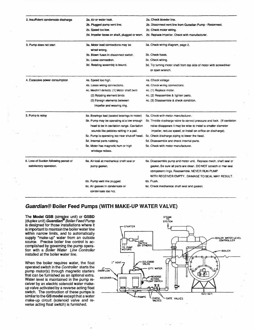
Guardian® Boiler Feed Pumps (WITH MAKE-UP WATER V Al VE}
The Model GSB (simglex unit) or GSBD (duplex unit) Guardian8 Boiler Feed Pump is designed for those installations where it is important to maintain the boiler water line within narrow limits, and to automatically supply "make-up• water from an outside source. Precise boiler line control is accomplished by governing the pump operation with a Boiler Water Line Controller installed at the boiler water line.
When the boiler requires water, the float operated switch in the Controller starts the pump motor(s) through magnetic starters that can be furnished as an optional extra. Water level is maintained in the pump receiver by an electric solenoid water makeup valve activated by a reverse acting float switch. The contruction of these pumps is similar to the GS model exceptthat a water make-up circuit (solenoid valve and reverse acting float switch) is furnished.
TO PUMP MOTORS
STEAM TO
SYSTEM
BOILER WATER LEVEL . CONTROLLER
BOILER
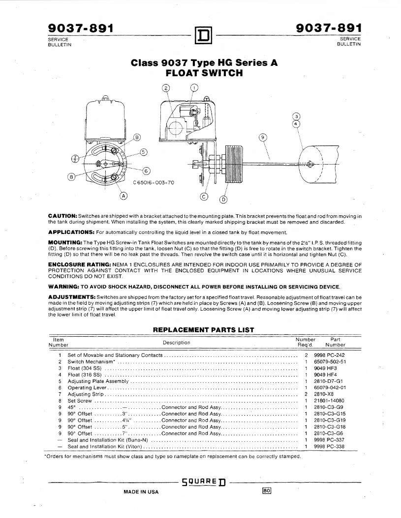
9037-891 9037-891 SERVICE BULLETIN
A
Class 9037 Type HG Series A FLOAT SWITCH
c 65016- 003-70
SERVICE BULLETIN
CAUTION: Switches are shipped with a bracket attached to the mounting plate. This bracket prevents the float and rod from moving in the tank during shipment. When installing the system, this clearly marked shipping bracket must be removed and discarded.
APPLICATIONS: For automatically controlling the liquid level in a closed tank by float movement.
MOUNTING: The Type HG Screw-in Tank Float Switches are mounted directly to the tank by means of the 2'h" I. P. S. threaded fitting (D). Before screwing this fitting into the tank, loosen Nut (C) so that the fitting (D) is free to rotate in the switch bracket. Tighten the fitting (D) so that there will be no leak past the threads. Then revolve the switch case until it is horizontal and tighten Nut (C).
ENCLOSURE RATING: NEMA 1 ENCLOSURES ARE INTENDED FOR INDOOR USE PRIMARILY TO PROVIDE A DEGREE OF PROTECTION AGAINST CONTACT WITH THE ENCLOSED EQUIPMENT IN LOCATIONS WHERE UNUSUAL SERVICE CONDITIONS DO NOT EXIST.
WARNING: TO AVOID SHOCK HAZARD, DISCONNECT ALL POWER BEFORE INSTALLING OR SERVICING DEVICE.
ADJUSTMENTS: Switchesare shipped from the factory set for a specified float tra.vel. Reasonable adjustment of float travel can be made in the field by moving adjusting strips (7) which are held in place by Screws (A) and (Bi. Loosening Screw (B) and moving upper adjustment strip (7) will affect the upper limit of float travel only. Loosening Screw (A) and moving lower adjusting strip (7) will affect the lower limit of float travel.
REPLACEMENT PARTS LIST Item
Number Description Number Req'd.
Part Number
Set of Movable and Stationary Contacts . ... . . .. .. . . . . . .... ... .. . . . . ... ...... . .. .. ......... . 2 Switch Mechanism• .. . . .. .... . .. . ...... . .. . . . ........ . . .. . . .... . ... . . . ........ . . . . . . . . . . . 3 Float (304 SS) . . . . ..... . .. . . .. .. . .... ..... . . . .. . .... .. . . .. . .. ... . . .. . . . . ... . . .. . . . . . ... . . 4 Float (316 SS) .. .. . . . ... .. . .. . . . . . . ... .. . .... . . . . ... . .. . . . . . .. . ... . . . . . .. .. . ... .. . . ... . . . 5 Adjusting Plate Assembly ... .... . . • .. . . ..... . . ... . . . . ..... . . . . ... . . .. .. . . .. .. . . . . . . . . .. ... 6 Operating Lever . .. . .. ... ....... .. • . . .. . . . . . . . ..... ..... .. . .. . . . . . .. .. ..... .. . .... . . .. . ... 7 Adjusting Strip . ..... . . . ... . . . .. . .. . . ... ... . . .. . . ..... .... . .. . .. . . .. . ...... . ... . .. .. . .. .. . 8 Set Screw . . ...... . . ... . . . .... . ..... . . .... . ... . . .. . . . . . ... . .. . . . . . .. . . . . ..... .. . ..... . . .. . 9 45° . . ... ........ . . . . - . . .. . . . .. . . . . Connector and Rod Assy . . .. . . .. .. .. . .. . .. .... . . . . .. . . 9 go• Offset . . . . . . . ... . 3" . . ..... .. . ... Connector and Rod Assy . .. . . . . ... . . . . .. ... .. .. .... . . . g go• Offset .. . .. ... . .. 4\4" . . ..... . . .. Connector and Rod Assy . .. . .. . .. .. ..... . . , .. . . . ... . . . g go• Offset .. . . . . . ... . 5" . ..... . . ... . . Connector and Rod Assy . .. . . . .. .. . . .. . . ..... ... .. . . . . g go• Offset . . . . . . .. . . . 7" . . ... . . . . ... . Connector and Rod Assy .. .. . . .. . . . .. . .. . .. .. . . . .. .. . .
Seal and Installation Kit (Buna-N) .. .... . . .. . . . . .. . . . . . . . . .. . . . . .... . . . . . . .. ... . .. . . . . ... . . Seal and Installation Kit (Viton) . .. .. . . . . . . .. . . . ... . . .... . . .. . . ..... . . . . . .. .. . . . . .. . . . .. . . . .
·orders for mechanisms must show class and type so nameplate on replacemen.t can be correctly stamped.
SOUR RED MADE IN USA
2 ggg8 PC-242 65079-502-51 904g HF3 go4g HF4 2810-D7-G1
1 65079-042-01 2 2810-XS
21801-14080 2810-C3-Gg 2810-C3-G15 2810-C3-G1g 2810-C3-G18 2810-C3- G6 gg98 PC-337 g9g8 PC-338
9037-891 SERVICE BULLETIN
mi .. n~~~~9_o_3_7_-s_9_1 l.:!::!J SERVICE BULLETIN
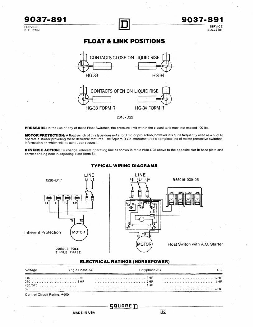
FLOAT & LINK POSITIONS
CONTACTS CLOSE ON LIQUID RISE
HG-33 HG-34
CONTACTS OPEN ON LIQUID RISE
HG-33 FORM R HG-34 FORM R
2810-022
PRESSURE: In the use of any of these Float Switches, the pressure limit within the closed tank must not exceed 100 lbs.
MOTOR PROTECTION: A float switch of this type does not afford motor protection, however it is quite frequently used as a pilot to operate a starter providing these desirable features. The Square D Co. manufactures a complete line of motor protective switches, information on which will be sent upon request.
REVERSE ACTION: To change, relocate operating link as shown in table 2810-022 above to the opposite slot in base plate and corresponding hole in adjusting plate (Item 5).
1530-017
Inherent Protection
DOUBLE POLE SINGLE PHASE
TYPICAL WIRING DIAGRAMS
LINE
1 r 965016-009-05
Float Switch with A.C. Starter
ELECTRICAL RATINGS (HORSEPOWER)
Voltage Single Phase AC
115 . . .. .. . ... . ... . . .... . ..... . 2 HP 230 . . . .. . ... . . .. . . . ... .. . .. . .. 3HP 460/575 . . .. .. .. . . . .. . . . .. . . . . 32 ... .......... ..... . . ... . . . . .
Control Circuit Rating: A600
Polyphase AC
.. ......... . ....... . .. . . . . . .. . . 3HP
..... ..... . . . .. ..... . .. . . ... . . . 5HP
. .. .. . ... . . • . . .. . ... . . .. . ..... . 1 HP
DC
'h HP 'h HP
V. HP
-------~---- SQURRE D ------------MADE IN USA

_90_3_8_-_8_9_3~~~~0C1]~~~~-9_0~38~·-8_9_3 SERVICE SERVICE BULLETIN BULLETIN
Class 9038 Type CG Series A MECHANICAL ALTERNATOR
CAUTION: Switches are shipped with a bracket attached to the mounting plate. This bracket prevents the float and rod from moving in the tank during shipment. When installing the system, this clearly marked shipping bracket must be removed and discarded.
APPLICATIONS: The Class 9038 Type C Mechanical Alternators serve to open and close an electric circuit by an upward and downward float movement. The forces are applied by means of a float operating between different liquid levels. The action is such that two switch units are alternated on successive cycles. If the liquid level continues to rise or fall with one pump in operation, the lever will continue to travel to a further position at which point the ""second" switch will be operated, throwing the stand-by pump across the line.
MOUNTING: The Class 9038 Type C Mechanical Alternators are mounted directly to the tank by means of the 2'h" NPT threaded fitting (D}. Before screwing this fitting into the tank. loosen Nut (C) so that the fitting (D) is free to rotate in the switch bracket. Tighten the fitting (D} so that there will be no leak past the threads. Then revolve the switch case until it is horizontal and tighten Nut (C).
PR!!i'SSURE: In the use of the CG Alternators, the pressure limit within the closed tank must not exceed 100 psi.
ELECTRICAL RATINGS (HORSEPOWER)
Voltage Single Phase AC
115 . . . . . ...... . . . . ... . .... . 230 . . ....... . . . ... . . . .. . ...... . .. . 460/ 575 ...... . .. . .... .. . . . ....... .
2HP 3HP
Polyphase AC
3HP 5HP 1HP
DC
'l1HP 'l1 HP
32 .. . ............ . . . . .. . . . •.. . . .. . . .. .. . • . . . · ......... 11.HP
Control Circuit Rating: A600
REVERSE OPERATION: Form R controls are arranged for reverse action. In this form, the contacts will open on increase in liquid level. It is not recommended that a change be made in the field from standard to reverse operation or vice versa.
MANUAL TRANSFER (LEAD-LAG) SELECTOR: Fo~m N3 switches have a manually engaged selector which voids alternation. The pump selected to lead always comes on first. With selector disengaged, the unit reverts to normal alternation.·
MOTOR PROTECTION: A control of this type does not afford motor protection. However, it is quite frequently used as a pilot to operate a starter providing this desirable feature . The Square D Company manufactures a complete line of motor protective devices. information on which will be sent upon request.
ENCLOSURE RATING: NEMA 1 ENCLOSURES ARE INTENDED FOR INDOOR USE PRIMARILY TO PROVIDE A DEGREE OF PROTECTION AGAINST CONTACT WITH THE ENCLOSED EQUIPMENT IN LOCATIONS WHERE UNUSUAL SERVICE CONDITIONS DO NOT EXIST.
WARNING: TO AVOID SHOCK HAZARD, DISCONNECT ALL POWER BEFORE INSTALLING OR SERVICING DEVICE.
ADJUSTMENTS: Switches are shipped from the factory set for a specified float travel. Reasonable adjustment of float travel can be made in the field by moving adjusting strips (7) which are held in place by Screws (A) and (9) . Loosening Screw (9) and moving upper ad1usting strip (7) will affect the upper limit of float travel only Loosening Screw (A) and moving lower ad1usting strip (7) will affect the lower limit of float travel.
REPLACEMENT PARTS LIST
Item Number Description
1 Set of Movable and Stationary Contacts .. . ....... ... .... . .. . . . ... . . . ...... ....... ..... ...... .. ........ . ... . 2 Switch Mechanism CG Types (including Form R) ....... . . . . ................. ... ....... . ..... . .. . ........ . . 3 Float (304 SS) .. .. ......... . .. . ........ ... ...... . ..... . ... . .... . .. . .... . . .. . .. . ·· ··· ········ · ····· · ·· ··· 4 Float (316 SS) . . . . . . . .. . . .. .. ...... ' .... . . . · · · · · · · .. · · · · · . • . · · · · · · · · · · · · · · · · · · · · · · · · · · .. · · · · · · · · · · · · · · · · 5 Adjusting Plate Assembly ..... . ..... ... ....... ... . . . .. . .......... . . ...... .. .. . ..... .. .... .. ........ . .. . . 6 Operating Lever .... . ............... .. . . ....... . . . .............. . . . ........ . ..•. . · · .. . ..•.. . ............ 7 Adjusting Strip . .. . . . ... . . . .. .......... . ... · · · · · · · · · · · · · .... . · · · · · · · · · · · · · · · · · · · · · · · · · · · · · · · · · · · · · · · · · · · 8 Set Screw .. .. . . . ... .. . . . .. .. .... . .... ....... ... . .. . .. .. .. . . . . ..... . . . . .. . .. . . .. . ·· ... . ...... .. .. . . . . . . . g 4'1•" . ....... . .... Connector and Rod Assy .............. .. ....... .. . . .... . . . ..... . . .. .. . .. ... . . ..... . .. . . 9 5" . . .... . .. . . . ... Connector and Rod Assy ....... . .... . .... . .... . . ........ . .. .... . . • ...... • . . . . ...... . ... 9 7" .... . .... . ..... Connector and Rod Assy .. . . . . . .. . . . . . . . . .... . .. . . .. . . . .. .. ..... ...... ... .. . .. ... ... . . .
Seal and Installation Kit (Buna-N) .. .. .. ... .. .. .... . .... . . .. .. . .... . .. . .. . . . . .... . .. . . . .. . . . . .. . ..... . . . . . Seal and ln$tallation Kit (Viton) .. ....... . ........ . .. . ... ... ..... . . . ....... .. ........ ... .. ...... . ........ .
SQURRE D MADE IN USA
Number Part Req"d . Number
2 9998 PC-242 1 1551-C7-G1 1 9049 HF3 1 9049 HF4 1 2810-D7-G1 1 6507~2-01
2 2810-X8 21801-14080 2810-C3-G19 2810-C3-G18 2810-C3-G6 9998 PC-337 9998 PC-338

Vent-RiteManufacturer of MEPCO Pump Packages
FORM SMV3618CPRINTED IN U.S.A.
1875 Dewey Avenue Benton Harbor, MI 49022 Phone 269-925-2522 Fax 269-925-7888
SMV3618C
100340 X 3.75
®