1856 ieee transactions on smart grid, vol. 7, …dkundur/pub_pdfs/farhamkuntsg16.pdfapproaches to...
TRANSCRIPT
1856 IEEE TRANSACTIONS ON SMART GRID, VOL. 7, NO. 4, JULY 2016
A Cyber-Enabled Stabilizing Control Schemefor Resilient Smart Grid Systems
Abdallah Farraj, Member, IEEE, Eman Hammad, Student Member, IEEE, and Deepa Kundur, Fellow, IEEE
Abstract—A parametric controller is proposed for transientstability of synchronous generators after the occurrence of a dis-turbance in the power grid. The proposed controller based onfeedback linearization control theory relies on receiving timelyphasor measurement unit (PMU) information from selected partsof the power grid to employ fast acting flywheels that are situatednear synchronous generators. The local storage devices aim tobalance a swing equation model of the synchronous generator todrive the associated rotor speed to stability. The advantages ofthe proposed controller include that it is tunable and integrateswell with existing governor controls in contrast to other forms ofPMU-based control. Further, a comparison is drawn between theproposed controller and recently proposed nonlinear controllersfor transient stabilization. Numerical results show the effective-ness and robustness of the proposed controller when applied tothe 39-bus 10-generator New England power system.
Index Terms—Cyber-physical systems, distributed control,phase cohesiveness, smart grid, system resilience, transientstability.
I. INTRODUCTION
SMART GRID systems employ advanced data acquisition,communications, and control to enable increased effi-
ciency, capacity, and consumer centricity of power delivery.In addition, they facilitate the integration of new forms ofgeneration including renewable sources thus helping to lowersociety’s carbon footprint. Given this modern vision for powerdelivery, natural questions arise as to how the effects of distur-bances on system operation should be mitigated. Specifically,the greater dependence on lower inertia renewable sourcesmakes the power grid more susceptible to incidental distur-bances in the form of common system faults and naturaldisasters [1]–[3]. Moreover, the greater dependence on infor-mation systems increases opportunities for cyber-attack andcoordinated cyber-physical disturbances [4]–[6].
In this paper, we investigate how distributed storage units,advanced sensors and communications can be leveragedfor improving system resilience through advanced control.
Manuscript received November 30, 2014; revised April 1, 2015; acceptedMay 17, 2015. Date of publication June 18, 2015; date of current versionJune 17, 2016. This work was supported in part by the U.S. National ScienceFoundation under Grant ECCS-1028246, and in part by the Natural Sciencesand Engineering Research Council of Canada under Grant RGPIN 227722.Paper no. TSG-01179-2014.
The authors are with the Department of Electrical and ComputerEngineering, University of Toronto, Toronto, ON M5S 3G4,Canada (e-mail: [email protected]; [email protected];[email protected]).
Color versions of one or more of the figures in this paper are availableonline at http://ieeexplore.ieee.org.
Digital Object Identifier 10.1109/TSG.2015.2439580
These entities represent a valuable and expanding asset basewithin smart grid systems that can be leveraged to bettermitigate both natural (physical) faults and intentional (cyber)attacks.
We assert that these cyber-physical disturbances must beaddressed through a defense-in-depth paradigm whereby pre-vention, detection, and reaction approaches for protectionare simultaneously employed at various levels. Preventativeapproaches aim to obstruct the impact of a disturbance bymaking it impossible to be carried out, as for example, in thecase of a cyber-attack, or by immediately isolating the associ-ated fault. Examples of preventative strategies are encryptionand secure communication protocols that represent an initiallevel of security against cyber-intrusions [4], [7]. Relays andcircuit breakers are also a form of initial defense to pre-vent the propagation of a severe fault [8], [9]. Detection isemployed when prevention is unsuccessful in thwarting a dis-turbance; these strategies make use of system measurementand models of (ab)normal behavior for the identification ofunwanted anomalies. Such techniques can be used to detectthe occurrence of an unwanted system state [10], success-ful cyber-attack [11], or a combination of both [12]. Reactionentails strategies to recover from a disturbance and includeapproaches to control system operation [13]. In this paper, wefocus on this last approach, specifically, to enhance systemresilience through the use of distributed control.
Recently, a distributed control paradigm based on flock-ing theory was proposed by Wei et al. [14]–[16] andWei and Kundur [17]. The framework represents an analogyfor transient stabilization providing a rich theoretical founda-tion upon which to prove stability under model assumptions.However, the controller can be costly computationally anddemonstrates a graceful yet slow time scale for stabilization ascommunication latency grows. Consequently, questions ariseas to whether more aggressive strategies exist that can drivethe power system to stability in a shorter period of time.
This paper proposes an agile low-complexity tunabledistributed controller that easily integrates with generatorgovernors. When the power system undergoes transient insta-bility, the proposed solution utilizes state information toexecute a feedback linearization controller that synchronizesthe generators more aggressively. Feedback linearization is awell-known approach that converts a nonlinear system (plant)into an equivalent linear system through controller design thataims to cancel out all (or part) of the nonlinear dynamics.Previously, it has been investigated in [18] to control theexcitation system of the generators; however, our proposed
1949-3053 c© 2015 IEEE. Personal use is permitted, but republication/redistribution requires IEEE permission.See http://www.ieee.org/publications_standards/publications/rights/index.html for more information.
FARRAJ et al.: CYBER-ENABLED STABILIZING CONTROL SCHEME FOR RESILIENT SMART GRID SYSTEMS 1857
solution utilizes external storage to stabilize the rotor speedand achieve phase cohesiveness among the generators.
The rest of this paper is organized as follows. The problemsetting is presented in Section II and the proposed controller isdetailed in Section III. Section IV investigates the performanceof the proposed controller. A study of control performanceunder practical limitations of the communication and infor-mation system is presented in Section V followed by theconclusion in Section VI.
II. DISTRIBUTED CONTROL SETTING
We assume that the smart grid is comprised of N agentswhereby each agent is comprised of the following.
1) A synchronous generator.2) An associated phasor measurement unit (PMU) that pro-
vides measurements of the generator rotor angle andspeed.
3) A distributed controller that processes PMU data fromlocal and neighboring agents.
4) A fast-acting storage device that can inject or absorb realpower in the system depending on the value of the con-trol signal, specifically, the controller actuates the localfast-acting storage entity such as a flywheel or otherdistributed storage source.
A communication network connects the PMUs and distributedcontrollers.
We consider the physical dynamics of each agent to dependon its own state (specifically, the state of its synchronous gen-erator) as well as the states of other agents in the overallmultiagent system. In such setting, a centralized controllerwould require that all agent states be transmitted to a com-mon location for processing and decision-making requiringsignificant communication overhead raising scalability issues.In contrast a decentralized controller would only require thestate of its own agent eliminating the need for significant com-munication; however, such an approach may experience longconvergence times for the controller tasks. In this paper, weconsider a distributed control paradigm where each controllermakes use of its own local state and those of its agent-neighbors that represent a subset of the remaining N − 1agents of the system. We assert that such a system balancesthe communication requirements with convergence speed.Mathematically, distinctions amongst the three approaches canbe represented as [19]
Ui =⎧⎨
⎩
Ui(��) centralized controlUi(xi, �i) distributed controlUi(xi) decentralized control
(1)
where Ui is the output of the controller at agent i, xi is the stateof agent i, �i is the state of the neighbor agents of agent i,and �� is the state of all agents in the system.
The overall multiagent system is considered to be cyber-physical in nature whereby the PMUs, distributed controllersand associated communication infrastructure form the cyber-resources and the synchronous generators and associatedpower system devices including fast-acting sources and storagerepresent the physical elements. The physical-to-cyber inter-face occurs at the sensors that convert physical measurements
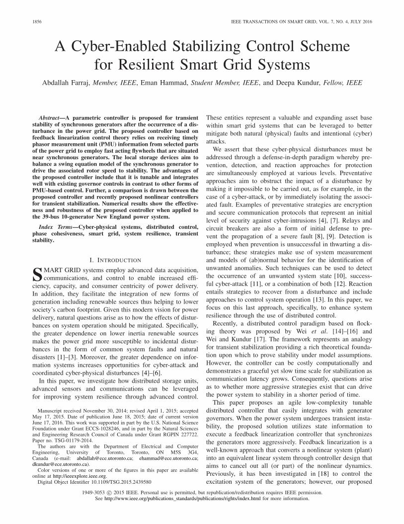
Fig. 1. Smart grid test system. (a) Original New England power system.(b) Cyber-enablement of system to include measurement device, distributedcontrol, and storage element.
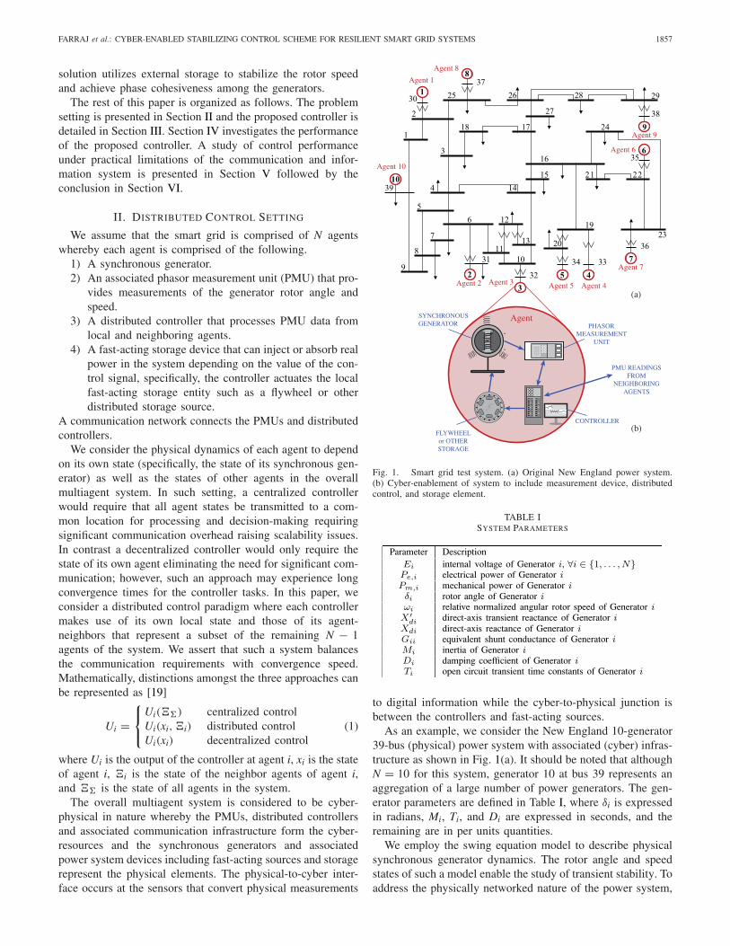
TABLE ISYSTEM PARAMETERS
to digital information while the cyber-to-physical junction isbetween the controllers and fast-acting sources.
As an example, we consider the New England 10-generator39-bus (physical) power system with associated (cyber) infras-tructure as shown in Fig. 1(a). It should be noted that althoughN = 10 for this system, generator 10 at bus 39 represents anaggregation of a large number of power generators. The gen-erator parameters are defined in Table I, where δi is expressedin radians, Mi, Ti, and Di are expressed in seconds, and theremaining are in per units quantities.
We employ the swing equation model to describe physicalsynchronous generator dynamics. The rotor angle and speedstates of such a model enable the study of transient stability. Toaddress the physically networked nature of the power system,
1858 IEEE TRANSACTIONS ON SMART GRID, VOL. 7, NO. 4, JULY 2016
we make use of Kron reduction to reduce the order of the inter-connections and determine effective mutual couplings betweenthe synchronous generators. Kron reduction is a graph-basedtechnique used in power systems to reduce the order of aninterconnected system [20]. In this process, the Kron reduc-tion transforms a complex power system into an equivalentgrid between the generators of the power system.
The relative normalized rotor angular speed of generator iis defined as ωi = (ωact
i − ωnom)/ωnom, where ωnom is thenominal angular speed of the power system and ωact
i is theactual angular speed of generator i (in radians per second).Let Ei, δi, and ωi denote the derivatives of Ei, δi, and ωi withrespect to time, respectively. Then, the third-order single-axismodel for generator i is represented as [18]
Ei = −1
Ti
[Ei + (
Xdi − X′di
)idi − Efi
]
δi = ωi
ωi = 1
Mi
[−Di ωi + Pm,i − Pe,i]
(2)
where Efi and idi are the value of the field excitation and thestator current of generator i, respectively. Further, the electricalpower of generator i is defined as [21]
Pe,i =N∑
k=1
|Ei| |Ek|[Gik cos (δi − δk) + Bik sin (δi − δk)] (3)
where Gik = Gki ≥ 0 is the Kron-reduced equivalent con-ductance between generators i and k, Bik = Bki > 0 isthe Kron-reduced equivalent susceptance between genera-tors i and k, and Yik = Gik + √−1 Bik is the Kron-reducedequivalent admittance between generators i and k. All of Yik,Gik, and Bik are expressed in per unit values. Let φik =arctan (Gik/Bik) and Pik = |Ei| |Ek| |Yik|, then the electricalpower of generator i is also calculated as
Pe,i = |Ei|2 Gii +N∑
k=1, k �=i
Pik sin (δi − δk + φik). (4)
Let Pa,i = Pm,i − Pe,i denote the accelerating power ofgenerator i, then the mechanical dynamics of a synchronousgenerator can be captured by investigating the swing equa-tion model, which is a subset of (2), and can be representedas [22], [23]
δi = ωi
ωi = 1
Mi
[−Di ωi + Pa,i]. (5)
We next introduce a cyber-controller that enables the overallcyber-physical smart grid system to achieve transient stabilityin the face of severe disturbance.
III. PARAMETRIC FEEDBACK LINEARIZATION
CONTROL FOR SMART GRID
Typically synchronous generators are equipped with powercontrol schemes (such as exciter and governor controls) thathelp to adjust a generator’s internal settings to respond tochanges in the overall power grid. However, these local con-trollers, partly due to their decentralized nature requiring
knowledge of only the local state xi, often exhibit slow reac-tion to rapid systemwide changes and can be insufficient toaddress significant disruptions. Thus, in this paper, we considerthe development of a local cyber-enabled controller at eachgenerator that provides faster response time by using PMUmeasurements of its own agent and those of its neighbors. Dueto the nonlinearity of the generator dynamics, we consider theuse of distributed parametric feedback linearization (PFL) con-trol that only requires knowledge of the local and neighboringstates �i. To design for more aggressive stabilization, we donot assume the existence of other local generator controls thatwould aid in stabilization to provide a more conservative viewof the stability problem during design.
Fig. 1(b) demonstrates the distributed control scenario inwhich the synchronous generator is equipped with a mea-surement device such as a PMU that obtains generator statereadings including rotor speed and phase angle and passesthe information to neighboring controllers. The controller thenobtains the local and neighboring PMU readings to computea signal that is injected into a local storage entity such as aflywheel. The flywheel then interfaces at the generator busabsorbing or injecting energy as needed.
The distributed external control can, therefore, be lever-aged to achieve stability and the corresponding cyber-enabledphysical dynamics can be described for generator i as
δi = ωi
ωi = 1
Mi
[−Di ωi + Pa,i + Ui]
(6)
where Ui is the power output of the flywheel such that a pos-itive value of Ui indicates that the controller of generator iis injecting power into the corresponding generator bus and anegative value implies that power is being absorbed.
In this paper, we assume Ui represents a feedback controlsignal computed from PMU measurements (or estimates) ofone or more state variables; accordingly, the feedback con-troller compares the measured value with a desired one andgenerates a control signal aimed to minimize the difference.
A. Transient Stability
We design the PFL controller to asymptotically drive therelative normalized rotor speed to zero after the occurrence ofa disturbance in the power grid; specifically, we require thatlim
t→∞ωi(t) = 0 ∀i ∈ {1, . . . , N} is achieved after the activation
of the distributed control.In feedback linearization, the control signal aims to can-
cel out nonlinear terms of the system dynamics such that theclosed-loop system exhibits (full or partial) linear dynamics.Thus, to cancel the nonlinear term of the swing equation(i.e., Pa,i/Mi = (Pm,i − Pe,i)/Mi), we let
Ui = −(Pa,i + αi ωi
)(7)
where (Di + αi) > 0 and αi ≥ 0 is called the frequencystability parameter. Consequently, the swing equation of theinterconnected power system (assuming exact knowledge ofthe system parameters), after implementing the PFL controller,
FARRAJ et al.: CYBER-ENABLED STABILIZING CONTROL SCHEME FOR RESILIENT SMART GRID SYSTEMS 1859
reduces to a decoupled linear equation of the form
xi = Ai xi (8)
where xi is the state variable of generator i. In this case
xi =[
δi
ωi
]
and Ai =[
0 10 −1
Mi(Di + αi)
]
. (9)
The eigenvalues of Ai are −1/Mi(Di + αi) and 0. Thezero eigenvalue produces an undetermined change of phaseuntil the frequency stabilizes; we introduce a phase cohesive-ness parameter later to address issues of phase trajectory. For(Di + αi) > 0, lim
t→∞ωi(t) = 0 [24, Th. 4.5]. Consequently,
the power system is stable under the PFL controller. Becausethe frequency stability parameter directly affects the valueof the nonzero eigenvalue, it is expected that higher values ofαi will drive the rotor speed of the system generators to fasterstability. However, higher values of αi implies that the PFLcontroller would need greater quantities of external power.
B. Phase Cohesiveness
The development of the PFL controller, as shown in (7),focuses on stabilizing the rotor speed of the system generators.However, for transient stability phase cohesiveness amongstsystem generators is also needed; specifically, the absolute dif-ference between the phase angle of any two generators shouldbe less than 100◦ [16], [25].
In order to simultaneously accomplish phase cohesiveness,the PFL controller can be modified as
Ui = −(Pa,i + βi
(δi − δ∗
i
) + αi ωi)
(10)
where βi ≥ 0 is denoted the phase cohesiveness parameter andδ∗ = [δ∗
1 , δ∗2 , . . . , δ∗
N]T is the desired phase angle of the systemgenerators. The βi(δi − δ∗
i ) term will drive the PFL controllerto settle the phase angle of the system generators on δ∗. Thevalues of δ∗ are selected such that
∣∣∣δ
∗i − δ∗
j
∣∣∣ ≤ 100◦, ∀i, j ∈ {1, . . . , N}. (11)
Consequently, phase cohesiveness is maintained during andafter the controller’s active time. Substituting the PFL con-trol (10) into (6) results in
xi = Ai xi + bi δ∗i (12)
where xi = [δi, ωi]T, Ai =[
0 1−βiMi
−(Di+αi)Mi
]
, and bi =[0,
βiMi
]T. It is straightforward to determine that the eigen-
values of Ai are
λ1,2 = 1
2Mi
[
−(Di + αi) ±√
(Di + αi)2 − 4βiMi
]
. (13)
For (Di + αi) > 0 and βi > 0, the eigenvalues lie in the left-hand complex plane resulting in global asymptotic stabilityunder the proposed PFL controller [24, Th. 4.5].
The reader should note that in cases that the fault is clearedknowledge of δ∗
i prior to the fault would allow a moreaggressive stabilization back to the former equilibrium state.However, use of a target phase is optional and transient sta-bilization control alone along with governor control as wediscuss next will also facilitate transient stabilization.
C. Robustness Study
In this section, we demonstrate the robustness of the PFLcontroller in the presence of measurement uncertainty andmodel error. Given that δ∗
i represents a set point for the gen-erator rotor angles, for mathematical convenience, we assumein this section that δi is an incremental version of the rotorangle state variable with an isolated equilibrium at the originthat represents convergence of the rotor angle of generator ito δ∗
i .Let the state variable measurements be denoted ωi and δi
that represent estimates of the normalized rotor speed ωi androtor angle δi, respectively. We model uncertainty in the non-linear component of the electromechanical dynamics usingPa,i. The overall relationships are represented as follows:
δi = (1 + eδi)δi
ωi = (1 + eωi)ωi
Pa,i = (1 + ePi)Pa,i (14)
where the parameters eδi , eωi , and ePi capture the degree ofuncertainty in the phase angle, rotor speed, and acceleratingpower of generator i, respectively.
The value of the feedback control signal in the presence ofuncertainty is given by
Ui = −(
Pa,i + βiδi + αi ωi
)(15)
which leads to system dynamics of the form
xi = Ai xi + fNL(xi) (16)
where
Ai =[
0 1
−βi(1+eδi
)
Mi− 1
Mi
[Di + αi
(1 + eωi
)]
]
(17)
and
fNL(xi) = [0,−ePi Pa,i
]T. (18)
1) Measurement Uncertainty: We first focus on the effectsof measurement error by neglecting model uncertainty; weassume ePi � 1. Thus, our dynamics can be approximated as
xi = Ai xi. (19)
It is straightforward to show that the eigenvalues of Ai aregiven by
λ1,2 = 1
2Mi
[
− (Di + αi
(1 + eωi
))
±√
(Di + αi
(1 + eωi
))2 − 4βi(1 + eδi
)Mi
]
.
(20)
A sufficient condition to ensure that both eigenvalues lie inthe left-hand plane is
eωi > −Di + αi
αiand eδi > −1 (21)
where we assume αi, βi > 0 which is necessary for astabilizing controller. Reformulating (21), we observe
1 + eωi = ωi
ωi> −Di
αiand 1 + eδi = δi
δi> 0. (22)
1860 IEEE TRANSACTIONS ON SMART GRID, VOL. 7, NO. 4, JULY 2016
This implies that as long as the rotor speed and angle estimatesωi and δi each have the correct sign as their ideal counterpartsωi and δi, stabilization will occur. In fact, in the case of rotorspeed, even if the sign of ωi is reversed, stabilization is pos-sible as long as |ωi| is bounded to be less than Di/αi|ωi|. Thereader is reminded that, as in the case of rotor angle, both ωi
and ωi represent incremental rotor speeds where 0 correspondsto the utility frequency of 50 or 60 Hz.
2) Model Error: We next consider the effect of model errorand assume that measurement uncertainty is negligible; that is,eδi , eωi � 1. Model uncertainty results in an additional non-linear term fNL(xi) in the right-hand side of the dynamics thatwe aim to account for using Lyapunov redesign [24].
Consider a Lyapunov function of the form
V(xi) = xTi Pxi (23)
where P is a 2 × 2 positive definite matrix. Taking the timederivative gives
V(xi) = xTi Pxi + xT
i Pxi (24)
=(
Ai xi + fNL(xi))T
Pxi (25)
+ xTi P
(Ai xi + fNL(xi)
)(26)
= xTi
(ATP + PA
)xi + 2PfNL(xi)xi. (27)
Let Q = −(ATP+PA) which can be shown to be positive def-inite given that A is Hurwitz. Moreover, we let R = 2PfNL(xi)
to give
V(xi) = −xTi Qxi + Rxi (28)
≤ −λmin(Q)‖xi‖2 + ‖R‖∞‖xi‖ (29)
= −λmin(Q)
(
‖xi‖ − ‖R‖∞λmin(Q)
)
‖xi‖ (30)
where ‖xi‖ ≥ 0 is the 2-norm of vector xi, λmin(Q) > 0represents the minimum eigenvalue of the positive definitematrix Q, and ‖R‖∞ > 0 is the maximum absolute value of theelements in R. Thus, V(xi) < 0 for ‖xi‖ > (‖R‖∞/λmin(Q)).Thus, we establish ultimate boundedness to a neighborhoodthat includes the origin. That is, the states are able to convergetoward the origin up to this neighborhood.
We see that this neighborhood decreases in size fordecreasing magnitudes of ePi as expected. Moreover, theneighborhood decreases as the minimum eigenvalue of Qincreases, which can be controlled by increasing controlgain αi and βi.
D. Integration With Governor Control
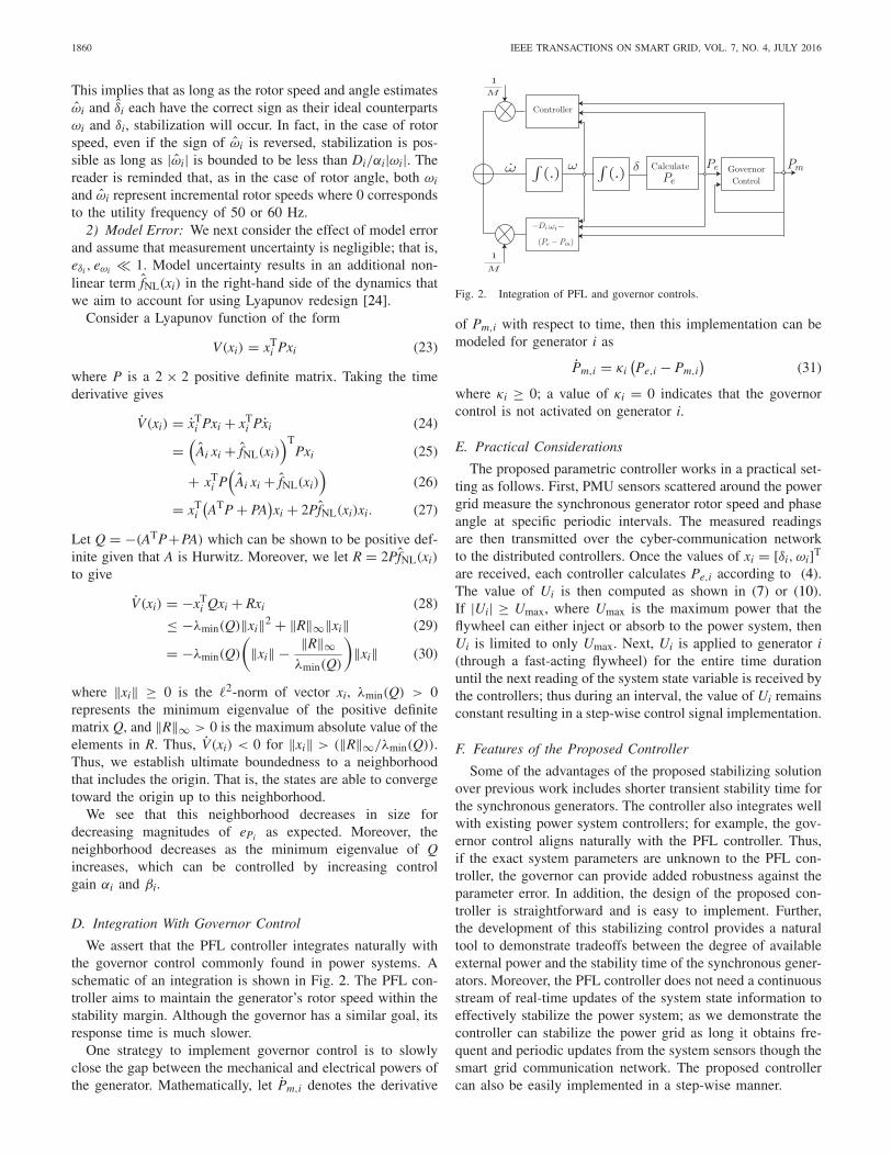
We assert that the PFL controller integrates naturally withthe governor control commonly found in power systems. Aschematic of an integration is shown in Fig. 2. The PFL con-troller aims to maintain the generator’s rotor speed within thestability margin. Although the governor has a similar goal, itsresponse time is much slower.
One strategy to implement governor control is to slowlyclose the gap between the mechanical and electrical powers ofthe generator. Mathematically, let Pm,i denotes the derivative
Fig. 2. Integration of PFL and governor controls.
of Pm,i with respect to time, then this implementation can bemodeled for generator i as
Pm,i = κi(Pe,i − Pm,i
)(31)
where κi ≥ 0; a value of κi = 0 indicates that the governorcontrol is not activated on generator i.
E. Practical Considerations
The proposed parametric controller works in a practical set-ting as follows. First, PMU sensors scattered around the powergrid measure the synchronous generator rotor speed and phaseangle at specific periodic intervals. The measured readingsare then transmitted over the cyber-communication networkto the distributed controllers. Once the values of xi = [δi, ωi]T
are received, each controller calculates Pe,i according to (4).The value of Ui is then computed as shown in (7) or (10).If |Ui| ≥ Umax, where Umax is the maximum power that theflywheel can either inject or absorb to the power system, thenUi is limited to only Umax. Next, Ui is applied to generator i(through a fast-acting flywheel) for the entire time durationuntil the next reading of the system state variable is received bythe controllers; thus during an interval, the value of Ui remainsconstant resulting in a step-wise control signal implementation.
F. Features of the Proposed Controller
Some of the advantages of the proposed stabilizing solutionover previous work includes shorter transient stability time forthe synchronous generators. The controller also integrates wellwith existing power system controllers; for example, the gov-ernor control aligns naturally with the PFL controller. Thus,if the exact system parameters are unknown to the PFL con-troller, the governor can provide added robustness against theparameter error. In addition, the design of the proposed con-troller is straightforward and is easy to implement. Further,the development of this stabilizing control provides a naturaltool to demonstrate tradeoffs between the degree of availableexternal power and the stability time of the synchronous gener-ators. Moreover, the PFL controller does not need a continuousstream of real-time updates of the system state information toeffectively stabilize the power system; as we demonstrate thecontroller can stabilize the power grid as long it obtains fre-quent and periodic updates from the system sensors though thesmart grid communication network. The proposed controllercan also be easily implemented in a step-wise manner.
FARRAJ et al.: CYBER-ENABLED STABILIZING CONTROL SCHEME FOR RESILIENT SMART GRID SYSTEMS 1861
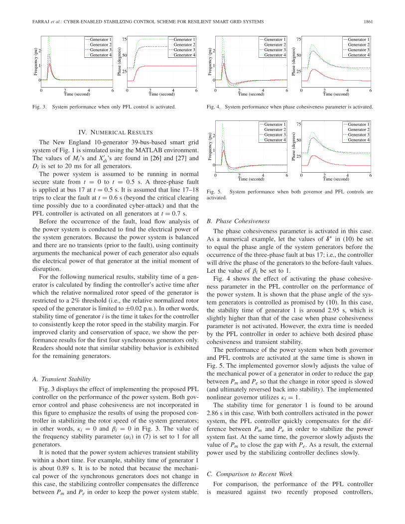
Fig. 3. System performance when only PFL control is activated.
IV. NUMERICAL RESULTS
The New England 10-generator 39-bus-based smart gridsystem of Fig. 1 is simulated using the MATLAB environment.The values of Mi’s and X′
di’s are found in [26] and [27] andDi is set to 20 ms for all generators.
The power system is assumed to be running in normalsecure state from t = 0 to t = 0.5 s. A three-phase faultis applied at bus 17 at t = 0.5 s. It is assumed that line 17–18trips to clear the fault at t = 0.6 s (beyond the critical clearingtime possibly due to a coordinated cyber-attack) and that thePFL controller is activated on all generators at t = 0.7 s.
Before the occurrence of the fault, load flow analysis ofthe power system is conducted to find the electrical power ofthe system generators. Because the power system is balancedand there are no transients (prior to the fault), using continuityarguments the mechanical power of each generator also equalsthe electrical power of that generator at the initial moment ofdisruption.
For the following numerical results, stability time of a gen-erator is calculated by finding the controller’s active time afterwhich the relative normalized rotor speed of the generator isrestricted to a 2% threshold (i.e., the relative normalized rotorspeed of the generator is limited to ±0.02 p.u.). In other words,stability time of generator i is the time it takes for the controllerto consistently keep the rotor speed in the stability margin. Forimproved clarity and conservation of space, we show the per-formance results for the first four synchronous generators only.Readers should note that similar stability behavior is exhibitedfor the remaining generators.
A. Transient Stability
Fig. 3 displays the effect of implementing the proposed PFLcontroller on the performance of the power system. Both gov-ernor control and phase cohesiveness are not incorporated inthis figure to emphasize the results of using the proposed con-troller in stabilizing the rotor speed of the system generators;in other words, κi = 0 and βi = 0 in Fig. 3. The value ofthe frequency stability parameter (αi) in (7) is set to 1 for allgenerators.
It is noted that the power system achieves transient stabilitywithin a short time. For example, stability time of generator 1is about 0.89 s. It is to be noted that because the mechani-cal power of the synchronous generators does not change inthis case, the stabilizing controller compensates the differencebetween Pm and Pe in order to keep the power system stable.
Fig. 4. System performance when phase cohesiveness parameter is activated.
Fig. 5. System performance when both governor and PFL controls areactivated.
B. Phase Cohesiveness
The phase cohesiveness parameter is activated in this case.As a numerical example, let the values of δ∗ in (10) be setto equal the phase angle of the system generators before theoccurrence of the three-phase fault at bus 17; i.e., the controllerwill drive the phase of the generators to the before-fault values.Let the value of βi be set to 1.
Fig. 4 shows the effect of activating the phase cohesive-ness parameter in the PFL controller on the performance ofthe power system. It is shown that the phase angle of the sys-tem generators is controlled as promised by (10). In this case,the stability time of generator 1 is around 2.95 s, which isslightly higher than that of the case when phase cohesivenessparameter is not activated. However, the extra time is neededby the PFL controller in order to achieve both desired phasecohesiveness and transient stability.
The performance of the power system when both governorand PFL controls are activated at the same time is shown inFig. 5. The implemented governor slowly adjusts the value ofthe mechanical power of a generator in order to reduce the gapbetween Pm and Pe so that the change in rotor speed is slowed(and ultimately reversed back into stability). The implementednonlinear governor utilizes κi = 1.
The stability time for generator 1 is found to be around2.86 s in this case. With both controllers activated in the powersystem, the PFL controller quickly compensates for the dif-ference between Pm and Pe in order to stabilize the powersystem fast. At the same time, the governor slowly adjusts thevalue of Pm to close the gap with Pe. As a result, the externalpower used by the stabilizing controller declines slowly.
C. Comparison to Recent Work
For comparison, the performance of the PFL controlleris measured against two recently proposed controllers,
1862 IEEE TRANSACTIONS ON SMART GRID, VOL. 7, NO. 4, JULY 2016
specifically, flocking control (see [14]–[17]), and consensusproportional integral (CPI) control (see [28]–[30]).
Flocking control was proposed by Wei et al. [15], [16], [31]and Wei and Kundur [17] to address generator synchronizationafter a severe disturbance such as a fault or denial-of-servicecyber-attack. This nonlinear control approach introduces acontrol input to shape the system dynamics to mimic that ofa flock of stable bird-like objects (boids) where agent phaseangle and rotor speed are analogous to boid position andvelocity, respectively. The dynamics exhibit flock centeringwhereby boids (agents) remain in close proximity, collisionavoidance where boids (agents) avoid colliding with neigh-bors, and velocity matching such that boids (agents) matchthe speed of neighbors [32]–[34]. The first two propertiesprovide phase synchronization while the latter providesspeed stabilization needed for transient stability [16]. Thecorresponding control Ui is calculated as [16]
U = � − Gδ − Bω · D − c(δ − δ0) (32)
where � = [�1,�2, . . . , �N]T and �i is defined as
�i =N∑
k=1,k �=i
⎡
⎣
t∫
t0
ρ(δi − δk) dt
⎤
⎦ (33)
where t0 is the time to activate the flocking control, t isthe time to calculate the value of the control, ρ is a controlfunction, c is a navigation term, δ0 = [δ01, δ02 , . . . , δ0N ]T
are the phase values at t0, D = [D1, D2, . . . , DN]T,δ = [δ1, δ2, . . . , δN]T, and ω = [ω1, ω2, . . . , ωN]T. Moreover,B and G are cyber-control matrices.
Andreasson et al. [28]–[30] proposed the application ofa CPI control strategy to affect the mechanical power of agenerator for automatic frequency control that is applied attwo levels. At the first level, the generator’s rotor speed isregulated against a reference speed. At the second level, thereference speed is updated to eliminate errors. Mathematically,the proposed CPI controller can be represented as [28]–[30]
Ui = αc(ω − ωi
)
˙ω = βc
⎛
⎝wnom − 1
N
N∑
j=1
ωj
⎞
⎠. (34)
The proposed PFL distributed controller aims to be morepractical than the flocking-based approach by being amenableto integration with governor control. Furthermore, by designit aims to achieve faster stabilization through the use of tun-able feedback linearization to control both rotor speed andphase angle. In contrast to the centralized CPI control thatmodulates the mechanical power of a designated generator,the PFL approach exploits cyber-enablement and the introduc-tion of distributed storage to harness fast-acting external powersources in a distributed manner thus reducing communicationoverhead.
The reader should note that for more consistent comparisonin simulations we have implemented the CPI controller as theinput to fast-acting flywheel storage opposed to that of control-ling mechanical power of the generator, which would exhibit
TABLE IIFAULT DETAILS
more sluggish behavior. In this way, the gains achieved by thecontroller design alone can more objectively be assessed.
D. Summary Results
Five fault case studies are considered in this paper as shownin Table II. The power system is assumed to be running innormal state from t = 0 to t = 0.5 s. A fault (three-phasefault for case study 1–4 and line-to-line asymmetrical faultin case study 5) occurs at the faulted bus at t = 0.5 s, thenthe tripped line is removed to clear the fault at t = 0.6 s.Finally, the controller is activated on corresponding generatorsat t = 0.7 s.
Tables III and IV detail the average stability time and con-trol power, respectively, of generators 1–9 for the differentcontrollers (governor, flocking, CPI, and proposed PFL) underthe five different case studies. The values of αc and βc are setto 0.25.
It is evident from the results of Table III that the PFLcontroller (with and without phase cohesiveness) outperformsthe flocking and CPI controllers. It is obvious that activatingthe phase cohesiveness parameter increases the stability timeslightly. Further, it is shown that savings in system stabilitycan be accomplished by activating both PFL and governorcontrols at the same time. Consequently, the integration ofthe PFL controller with the governor control yields morerobustness.
The reader should note that the generator models for con-troller derivation and simulation are distinct. For tractability,PFL control assumes a swing equation model of a synchronousgenerator widely used in the literature that is well suitedfor transient stability analysis. In contrast, empirical resultsmake use of the third-order single-axis model of (2) thatadditionally accounts for the time-vary nature of the internalvoltage and electrical dynamics within a synchronous gener-ator. Thus, we believe that the simulations represent a flavorof the performance of the controller within a real system.
V. PERFORMANCE UNDER PRACTICAL LIMITATIONS
This section investigates the performance of the PFL con-troller against some practical limitations. Further, the relationbetween the stability time and the controller parameters is con-sidered. For the following numerical studies, case study 1 isconsidered where we set αi = 1, βi = 0, and κi = 0.
A. Cyber-Limitations
The performance of the proposed controller is evaluatedagainst the physical limits of the external power source, thesampling frequency of the measurements, the signal-to-noise

FARRAJ et al.: CYBER-ENABLED STABILIZING CONTROL SCHEME FOR RESILIENT SMART GRID SYSTEMS 1863
TABLE IIIAVERAGE STABILITY TIME (s)
TABLE IVAVERAGE CONTROL POWER (P.U.)
ratio (SNR), and the communication latency between thecontrol center and sensors.
1) Limits on External Power Source: The PFL controllerrelies on a fast-acting external power injection and absorp-tion source, Ui, to contribute to the power system dynamics.However, Ui will have practical physical limitations, specif-ically, |Ui| ≤ Pmax,i; this power limit can be a result of thenumber and capacity of the storage batteries employed, forexample. In this paper, Pmax,i is set to a percentage of themechanical power of each generator Pm,i before the occur-rence of the fault. In other words, Pmax,i = γ /100 Pm,i, where0 < γ ≤ 100 is the power limit percentage.
The effects of the external power limit are shown inFig. 6(a). It is noted that the controller performs well when theexternal power supply does not have highly restrictive limits.For reasonable values of external power limit the PFL con-troller can effectively stabilize the New England power systemwithin few seconds.
2) Measurement Sampling Frequency: The digital natureof PMU sensors requires that measurements be sampled priorto communication. As the value of the sampling period Ts isdecreased, the PFL controller obtains more frequent updatesof the system state variable x. To account for the effect ofsampling period, U is implemented in a step-wise manner;specifically, it can be considered a function of δ(nTs) andω(nTs) for the duration nTs ≤ t < (n + 1)Ts, where n ≥ 1 isa positive integer.
Fig. 6(b) shows the performance of the PFL controlleragainst Ts. As the value of Ts increases, the stability time ofthe system generators increases; however, even when the sam-pling period is approximately 200 ms, the different generatorscan be stabilized within few seconds.
The reader should note that the robustness of the pro-posed PFL controller to a broad range of sampling periodsTs has other implications. Specifically, our paradigm makesuse of fast-acting storage technologies to stabilize the system.Questions naturally arise as to the performance of flywheelsand batteries in providing sufficient tracking of the control sig-nal Ui. We assert that given the system is robust to sampling
periods of up to 200 ms and that current reports on responsetimes of utility scale energy storage systems are in the orderof 0.35–20 ms [35] with flywheel technology reported to havethe potential of 0.5 MW [36], our paradigm has the poten-tial to perform well by leveraging a variety of new storagetechnologies.
Moreover, current standards for synchrophasor measure-ments for power systems such as the IEEE 37.118 standardspecify sampling rates in the range 10–120 samples/s that cor-respond to sampling periods of 8.3–100 ms. Thus, the PFLcontroller has the potential to perform well within current andexpected future standards.
3) Sensor Noise: SNR (in units of dB) is defined asSNR = 10 log10(ES/EN) where ES is the energy of the origi-nal uncorrupted signal, and EN is the energy of the associatednoise computed as the deviation between the original signalat the source and the version received at the controller. SNRis a measure of the quality of the received sensor signal atthe controller; the higher the value of SNR, the higher thefidelity and accuracy of the readings employed to computecontrol.
Fig. 6(c) displays the effect of SNR on the performance ofthe PFL controller. It is noted that the controller is robust tonoise given that a relatively modest value of SNR (achiev-able by most modern smart grid sensors) is required by thecontroller to stabilize the power system.
4) Communication Latency: Communication latency canoccur in the cyber-infrastructure due to sampling and quan-tization time, encryption, channel propagation, and queueingdelays. Latency can be variable or fixed for each data trans-mission. The case of fixed latency is considered in this paper;this means that all data packets sent by the sensors to thecontroller experience the same amount of delay. To reflect theeffect of latency on the controller, U(t) is a function of δ(t−τ)
and ω(t − τ) where τ is the communication latency.Fig. 6(d) displays the effect of communication latency on
the controller performance. It is noted that the PFL con-troller is robust to reasonable communication delays. However,when the communication latency is higher than 175 ms,

1864 IEEE TRANSACTIONS ON SMART GRID, VOL. 7, NO. 4, JULY 2016
Fig. 6. Effects of cyber-limitations. (a) External power limit.(b) Measurement sampling period. (c) Sensor noise. (d) Communicationlatency.
Fig. 7. Comparison of the effects of latency.
Fig. 8. Effect of frequency stability and phase cohesiveness parameters.(a) Frequency stability parameter. (b) Phase cohesiveness parameter.
the synchronous generators cannot be stabilized by the PFLcontroller within the simulation run time. Further, Fig. 7 pro-vides a performance comparison between the PFL, flocking,and CPI control schemes versus latency.
B. Controller Parameters
Fig. 8(a) displays the stability time of the power sys-tem as a function of the frequency stability parameter (αi),where βi = 0 in this case. It is shown in (9) that the term(Di + αi)/Mi controls the exponent of decay of ωi; thus, therelative normalized rotor speed of the generators approaches
zero with a rate that depends on the frequency stability param-eter. Consequently, higher values of αi lead to faster decayand shorter stability times as confirmed by the results of thisfigure.
The relation between the stability time and phase cohesive-ness parameter is shown in Fig. 8(b). Compared to the caseof no phase cohesiveness (i.e., βi = 0), it is observed that thestability time is higher when βi > 0. However, for values ofβi > 1, the stability time is slightly decreasing.
VI. CONCLUSION
This paper proposes a stabilizing controller for smartgrid systems under severe fault or malfunction of protectiondevices. The proposed parametric controller relies on feedbacklinearization theory. System state information is collected bysensors and transmitted through a communication network todistributed controllers. Based on the received data, a PFL con-trol is applied using fast-acting flywheels situated near thesynchronous generators to balance the swing equation anddrive the power system to stability.
System performance is investigated when the proposed con-troller is applied to the New England 39-bus 10-generator testsystem. Further, the performance is studied when both pro-posed and governor controls are activated. Results demonstratethe effectiveness of the proposed controller in stabilizing thepower grid and achieving more resilience to disturbances.
REFERENCES
[1] E. Vittal, A. Keane, J. Slootweg, and W. Kling, “Impacts of wind poweron power system stability,” in Wind Power in Power Systems, 2nd ed.Hoboken, NJ, USA: Wiley, 2012.
[2] J. Hossain and H. Pota, Robust Control for Grid Voltage Stability: HighPenetration of Renewable Energy. New York, NY, USA: Springer, 2014.
[3] Y. Zhang, S. Zhu, R. Sparks, and I. Green, “Impacts of solar PV genera-tors on power system stability and voltage performance,” in Proc. IEEEPower Energy Soc. Gen. Meeting, San Deigo, CA, USA, Jul. 2012,pp. 1–7.
[4] T. Flick and J. Morehouse, Securing the Smart Grid: Next GenerationPower Grid Security. Boston, MA, USA: Syngress, 2011.
[5] S. Liu, S. Mashayekh, D. Kundur, T. Zourntos, and K. Butler-Purry,“A framework for modeling cyber-physical switching attacks in smartgrid,” IEEE Trans. Emerg. Topics Comput., vol. 1, no. 2, pp. 273–285,Dec. 2013.
[6] S. Liu, B. Chen, T. Zourntos, D. Kundur, and K. Butler-Purry,“A coordinated multi-switch attack for cascading failures in smart grid,”IEEE Trans. Smart Grid, vol. 5, no. 3, pp. 1183–1195, May 2014.
[7] W. Stallings, Network Security Essentials: Applications and Standards,5th ed. Upper Saddle River, NJ, USA: Pearson, 2013.
[8] S. H. Horowitz and A. G. Phadke, Power System Relaying, 4th ed.Hoboken, NJ, USA: Wiley, 2014.
[9] B. Ravindranath and M. Chander, Power System Protection andSwitchgear. New Delhi, India: New Age Int., 2011.
[10] A. Abur and A. Expósito, Power System State Estimation: Theory andImplementation. New York, NY, USA: Marcel Dekker, 2004.
[11] R. Berthier, W. Sanders, and H. Khurana, “Intrusion detection foradvanced metering infrastructures: Requirements and architectural direc-tions,” in Proc. IEEE Int. Conf. Smart Grid Commun., Gaithersburg, MD,USA, 2010, pp. 350–355.
[12] S. Zonouz et al., “SCPSE: Security-oriented cyber-physical state esti-mation for power grid critical infrastructures,” IEEE Trans. Smart Grid,vol. 3, no. 4, pp. 1790–1799, Dec. 2012.
[13] P. Kundur, Power System Stability and Control (EPRI Power SystemEngineering Series). New York, NY, USA: McGraw-Hill, 1994.
[14] J. Wei, D. Kundur, T. Zourntos, and K. Butler-Purry, “A flocking-based paradigm for hierarchical cyber-physical smart grid modelingand control,” IEEE Trans. Smart Grid, vol. 5, no. 6, pp. 2687–2700,Nov. 2014.

FARRAJ et al.: CYBER-ENABLED STABILIZING CONTROL SCHEME FOR RESILIENT SMART GRID SYSTEMS 1865
[15] J. Wei, D. Kundur, and T. Zourntos, “On the use of cyber-physicalhierarchy for smart grid security and efficient control,” in Proc. IEEECan. Conf. Elect. Comput. Eng. (CCECE), Montreal, QC, Canada,Apr./May 2012, pp. 1–6.
[16] J. Wei, D. Kundur, T. Zourntos, and K. L. Butler-Purry, “A flocking-based dynamical systems paradigm for smart power system analysis,”in Proc. IEEE Power Energy Soc. Gen. Meeting (PESGM), San Diego,CA, USA, Jul. 2012, pp. 1–8.
[17] J. Wei and D. Kundur, “Two-tier hierarchical cyber-physical securityanalysis framework for smart grid,” in Proc. IEEE Power Energy Soc.Gen. Meeting (PESGM), San Diego, CA, USA, Jul. 2012, pp. 1–5.
[18] J. W. Chapman, M. D. Ilic, C. A. King, L. Eng, and H. Kaufman,“Stabilizing a multimachine power system via decentralized feedbacklinearizing excitation control,” IEEE Trans. Power Syst., vol. 8, no. 3,pp. 830–839, Aug. 1993.
[19] M. Andreasson, “Control of multi-agent systems with applications to dis-tributed frequency control of power systems,” Licentiate thesis, Autom.Control Lab., KTH School Elect. Eng., Stockholm, Sweden, Mar. 2013.
[20] F. Dörfler and F. Bullo, “Kron reduction of graphs with applications toelectrical networks,” IEEE Trans. Circuits Syst. I, Reg. Papers, vol. 60,no. 1, pp. 150–163, Jan. 2013.
[21] A. R. Bergen and V. Vittal, Power Systems Analysis, 2nd ed. UpperSaddle River, NJ, USA: Prentice-Hall, 2000.
[22] P. M. Anderson and A. A. Fouad, Power System Control and Stability(IEEE Power Systems Engineering Series). Piscataway, NJ, USA: IEEE-Press, 1994.
[23] F. Dörfler and F. Bullo, “Synchronization and transient stability in powernetworks and non-uniform Kuramoto oscillators,” in Proc. Amer. ControlConf. (ACC), Baltimore, MD, USA, Jun./Jul. 2010, pp. 930–937.
[24] H. K. Khalil, Nonlinear Systems, 3rd ed. Upper Saddle River, NJ, USA:Prentice-Hall, 2002.
[25] P. W. Sauer and M. A. Pai, Power System Dynamics and Stability.Upper Saddle River, NJ, USA: Prentice-Hall, 1998.
[26] T. Athay, R. Podmore, and S. Virmani, “A practical method for thedirect analysis of transient stability,” IEEE Trans. Power App. Syst.,vol. PAS-98, no. 2, pp. 573–584, Mar. 1979.
[27] B. Pal and B. Chaudhuri, Robust Control in Power Systems (PowerElectronics and Power Systems Series). New York, NY, USA: Springer,2006.
[28] M. Andreasson, H. Sandberg, D. V. Dimarogonas, and K. H. Johansson,“Distributed integral action: Stability analysis and frequency control ofpower systems,” in Proc. IEEE Annu. Conf. Decis. Control (CDC), Maui,HI, USA, Dec. 2012, pp. 2077–2083.
[29] M. Andreasson, D. V. Dimarogonas, K. H. Johansson, and H. Sandberg,“Distributed vs. centralized power systems frequency control,” inProc. Eur. Control Conf. (ECC), Zurich, Switzerland, Jul. 2013,pp. 3524–3529.
[30] M. Andreasson, D. V. Dimarogonas, H. Sandberg, and K. H. Johansson,“Distributed control of networked dynamical systems: Static feedbackand integral action and consensus,” IEEE Trans. Autom. Control, vol. 59,no. 7, pp. 1750–1764, Jul. 2014.
[31] J. Wei, D. Kundur, T. Zourntos, and K. L. Butler-Purry, “Probing the tell-tale physics: Towards a cyber-physical protocol to mitigate informationcorruption in smart grid systems,” in Proc. IEEE Int. Conf. Smart GridCommun. (SmartGridComm), Tainan, Taiwan, Nov. 2012, pp. 372–377.
[32] C. W. Reynolds, “Flocks, herds, and schools: A distributed behav-ioral model,” in Proc. Annu. Conf. Comput. Graph. Interact. Tech.(SIGGRAPH), vol. 21. Dallas, TX, USA, Jul. 1987, pp. 25–34.
[33] R. Olfati-Saber, “Flocking for multi-agent dynamic systems: Algorithmsand theory,” IEEE Trans. Autom. Control, vol. 51, no. 3, pp. 401–420,Mar. 2006.
[34] R. Olfati-Saber, J. A. Fax, and R. M. Murray, “Consensus and coop-eration in networked multi-agent systems,” Proc. IEEE, vol. 95, no. 1,pp. 215–233, Jan. 2007.
[35] R. Carnegie, D. Gotham, D. Nderitu, and P. Preckel, “Utilityscale storage systems: Benefits, applications, and technolo-gies,” State Util. Forecast. Group, Purdue Univ., West Lafayette,IN, USA, Tech. Rep., Jun. 2013. [Online]. Available: http://www.purdue.edu/discoverypark/energy/assets/pdfs/SUFG/publications/SUFG%20Energy%20Storage%20Report.pdf
[36] A Flywheel Like No Other. [Online]. Available: http://temporalpower.com/what-we-do/technology/flywheels/, accessed Mar. 28, 2015.
Abdallah Farraj (S’11–M’12) received the B.Sc.and M.Sc. degrees in electrical engineering from theUniversity of Jordan, Amman, Jordan, in 2000 and2005, respectively, and the Ph.D. degree in electricalengineering from Texas A&M University, CollegeStation, TX, USA, in 2012.
He is currently a Postdoctoral Fellow with theUniversity of Toronto, Toronto, ON, USA. He isa Fulbright Scholar. His current research interestsinclude cognitive communications, cyber-security ofsmart grids, downhole telemetry systems, wireless
communications, and signal processing applications.
Eman Hammad (S’14) received the B.Sc. degreefrom the University of Jordan, Amman, Jordan,and the M.Sc. degree from Texas A&M University,College Station, TX, USA, in 2000 and 2011,respectively, both in electrical engineering. Sheis currently pursuing the Ph.D. degree with theDepartment of Electrical Engineering, University ofToronto, Toronto, ON, USA.
She had a long professional experience in the ITindustry in Jordan. Her current research interestsinclude cyber-physical systems with particular inter-
est in cyber-security, resilient control, and cooperative game theory in thecontext of smart grids.
Ms. Hammad was a recipient of the Hatch Graduate Scholarship forSustainable Energy Research and the Best Poster Award from the Institutefor Sustainable Energy 2014 Symposium. She served as a Technical ProgramCommittee and an Organizing Committee Member for several conferences andworkshops. She is currently serving as the IEEE Toronto Computer SocietyChapter Chair.
Deepa Kundur (S’91–M’99–SM’03–F’15) receivedthe B.A.Sc., M.A.Sc., and Ph.D. degrees from theUniversity of Toronto, Toronto, ON, Canada, in1993, 1995, and 1999, respectively, all in electricaland computer engineering.
She was a Professor with the Edward S. Rogers Sr.Department of Electrical and Computer Engineering,University of Toronto. She is currently an AssociateChair with the Division of Engineering Science,University of Toronto. She is a recognized author-ity on cyber-security issues and has appeared as an
expert in popular television, radio, and print media. Her current researchinterests include interface of cyber-security, signal processing, and complexdynamical networks.
Prof. Kundur was a recipient of Best Paper Recognitions from the2008 INFOCOM Workshop on Mission Critical Networks, the 2011 CyberSecurity and Information Intelligence Research Workshop, and the 2012 IEEECanadian Conference on Electrical and Computer Engineering. She has par-ticipated on several editorial boards. She is currently an Associate Editor ofthe IEEE TRANSACTIONS ON INFORMATION FORENSICS AND SECURITY,and a General Chair for the IEEE GlobalSIP’15 Symposium on Signal andInformation Processing for Optimizing Future Energy Systems, the 2015International Conference on Smart Grids for Smart Cities, and the 2015 SmartGrid Resilience Workshop at the IEEE GLOBECOM 2015.