1852 - marine steam engineers manual
DESCRIPTION
Written just 40 years after the appearance of Henry Bell's "Comet", the first successful seagoing steamship, this important manual covers everything necessary to know about the contruction and operation of engines and boilers of paddle and screw steamers of the period.TRANSCRIPT

RUDIMENTARY TEEATISEOIv
THE MARINE ENGINE,*
>
AND ON
Fcssels, an& tfie
EOBEET MUEB-AT, C.E.
illustrations.
Double Part Price Tu:v SJ- tilings
: JOHN v>


FRONTISPIECE.
SECTION OF STERN OF SCREW VESSEL IN THE ROYAL NAVY, SHOW-ING THE TRUNK OR A PORTION THROUGH WHICH THE SCREW IS
RAISED OUT OF WATER WHEN DISCONNECTED.

RUDIMENTARY TREATISE^
ON
M A K I N E ENGINESAND
STEAM VESSELS;
TOGETHER WITH
practical Bernards
ON THE
SCREW AND PROPELLING POWER
AS USED IN THE EOYAL AND MERCHANT NAVY.
BY ROBERT MURRAY, C.E.
SECOND EDITION.
^\ *yx/* \
Hontion: VJOHN WEALE,
ARCHITECTUEAL LIBEAEY, 59, HIGH HOLBOEN.
MDCCCLII.

LONDON :
8XVM* AND CO., PKINTKR8, Bi,L YAlil),

PREFACE.
Is" adding a treatise on the Management of Marine
Engines to Mr. Weale's Series of Budimentary Works,
the Author trusts that it may prove a useful auxiliary to
the various classes of practical men interested in the per-
formance of our Steam Marine, whether in the Eoyal
Navy or Merchant Service. Desirous of being under-
stood alike by the non-professional man of business, who
from his desk in the city controls the operations of a fleet
of steam ships, as by the humblest assistant in the duties
of the engine-room, he has endeavoured to express himself
in as concise and matter-of-fact a manner as possible, avoid-
ing as far as may be the use of technical language and
mathematical demonstration, without attempting, at the
same time, to render the text intelligible to the wholly
uninitiated, by perplexing it with notes and explanations
which ought to suggest themselves to every one acquainted
with the rudiments of mechanical science. Some very es-
sential Tables of the details of Engines and Vessels are
added in the Appendix ;and such technical terms as do
necessarily occur will be found explained in the Glossary
at the end, and several corrections made in this second
Edition.
March Wth, 1852.


CONTENTS
CHAPTER I.
GENERAL DESCRIPTION AND VARIETIES OF THE MARINE
ENGINE.
PAGE
A previous acquaintance with the principles of the steam engine
presupposed ........ 1
General description of the marine engine ... .1Its varieties of form ........ 2
The fly-wheel inapplicable ...... .2Consequent necessity for combining two engines on one shaft . 3
Single engines are sometimes employed ... .3High-pressure engines rarely used ...... 4
The side-lever engine : its advantages .... .4Ditto, ditto : its disadvantages ..... 6
Adoption of the direct-acting engine .... .6Varieties of the direct -acting engine ..... 6
Shortness of stroke a defect ..... .13The steeple engine . . . . . . . .13The double-cylinder engine . . . . . . .13The oscillating engine . . . . . . .15Machinery for screw propulsion . . . . . .16Internal gearing .16Protection of the machinery from shot . . . . .17

Till CONTENTS.
CHAPTER II.
DETAILS OF THE MARINE ENGINE : THEIR PROPORTIONS
AND USES.
PAGE
The steam pipes . 18
The throttle valve .19The expansion valve . . . . . . . .19Stephenson's link-motion applied to give expansion . . 21
How to set the slide valves 21
The lap of the valve .22The lead of the valve 23
Reversing the engines . . . . . . .23Expanding by means of the lap of the valve . . . .24The blow-through and snifting valves .... .25Clothing the cylinder, &c 25
Clearance of the piston ...... .25Priming or escape valves ....... 25
Packing for the piston ...... .26The condenser ......... 26
The injection valve ....... .26Temperature of the condenser ...... 27
Elasticity of watery vapour at different temperatures . .27Velocity of flow of the injection water 27
The barometer gauge ....... .28Ditto, sources of error 28
An improved barometer for the condenser ... .29Evils arising from the use of sea water for condensation . . 30
Surface condensation attempted and found ineffective . . 30
Hall's patent condensers 31
The air pump . . . . * . . . .31The feed pumps 31
The bilge pumps ....... .32The hand pump connected with the large engines . . .32
Ditto, driven by a supplementary engine or "donkey" 32

CONTENTS.
CHAPTER III.
THE MARINE BOILER : ITS GENERAL PROPORTIONS, AND THE
PRINCIPLES CONCERNED IN ITS OPERATION.
PAGE
Peculiarities of the marine boiler . . . 33
The flue boiler .33The form of the flues ........ 33
The arrangement of the heating surface ... .33Horizontal heating surface the best...... 34
Bottom heating surface inefficient .... .34Disadvantages of flue boilers ....... 35
Tubular boilers ....... .35Furnaces .......... 35
Fire bars ........ .36The direct impact of the flame to be avoided . . . .36The bridge .36The water spaces ......... 36
Requisite amount of heating surface .... .37Areas of flues and tubes........ ^8
A roomy furnace desirable ...... .38Combustion is checked by the carbonic acid . . . .38Loss of heat attending the combustion of the inflammable gases 38
Formation of carbonic oxide ..... .39Smoke-burning apparatus ....... 39
Recapitulation . . . . . . . . .40Clothing marine boilers is sometimes found to be prejudicial . 40
Bedding the boilers 41
Galvanic action to be guarded against . . . . .41
Copper boilers compared with iron ones . . . . . 42

CONTENTS.
CHAPTER IV.
THE MARINE BOILER: MANAGEMENT OF THE FIRES.
PAGE
The skilful management of the machinery necessary for its
efficiency ......... 43
Economy of steam is the main question . . . .43The generation of heat in the furnaces . . . . .43The management of the fires ..... .44The effects of mismanagement . . . . . .44Feeding the furnaces . . . . . . . , 44
Clearing the bars . . . . . . . .45Keeping the fire doors shut...... .45Levelling the fuel ......... 45
Each watch to leave their fires clean . . . . . 4>>
Forcing the fires is expensive of fuel . . . . .46The cinders to be reburnt when practicable . . . .46Superior economy of large boilers . . . . . .47The boiler-power is subdivided into sections . .47How to manage the boilers when full steam is not wanted . . 4"
Lord Dundonald's experiments on slow combustion in marine
boilers . . . . . . . . . .48Experiments with a tubular marine boiler in Woolwich Dockyard 48
Dimensions and description of the experimental boiler . .49Dimensions of the boilers of the Janus . . . . .50Table of these experiments . . . . . . .51Slow combustion in marine boilers is seldom practicable . .52Regulation of the draft ...... .52Banking-up the fires ........ 52
To get up the steam rapidly .53No water to be thrown in the ash pits . . . . .53

CONTENTS. XI
CHAPTER V.
THE MARINE BOILER : MANAGEMENT OF THE WATER AND
STEAM.
PAGR
Regular supply of water to the boilers ... .54The water level must not rise too high . . . . .54Water granges ........ .55The glass water gauge ........ 55
The brass gauge cocks ...... .56Only one feed pump to be worked ...... 56
Amount of the brine abstracted ..... .57Proportions of salt in sea water from different localities . . 57
Analysis of deep sea water . . . . . . .57Blowing-off ......... 58
The brine pumps ....... .58Lamb's blow-off apparatus . . . . . . .58The refrigerator ........ .59Attempts made to supersede blowing-off . . . . .59
by mechanical means ..... .GOby chemical means ....... 60
The brine pumps found to be perfectly efficient at a trifling ex-
penditure of fuel....... .61Salinometers . . . . . . . . . .61The thermometer used as a salinomefer ... .61The hydrometer ditto, ditto ...... 63
Seaward's salinometer ...... .64Cases in which the amount of blow-off may be diminished . 65
How to manage in case the blow-off cock sets fast . .65The safety valve, its area ....... 65
Ditto, its manner of loading ... .65Ditto, occasional defects ....... 66
How to manage in case the safety valve sticks fast . . 66
Steam gauge .......... 67
The vacuum, or reverse valve . . . . . .67Supply of air to the fires ....... 68
Staying boilers at long distances is very objectionable . . 68

Xll CONTENTS.
CHAPTER VI.
MANAGEMENT OF THK ENGINES,
PAGEThe bearings require attention 70
How to test the tightness of an engine before starting . . 70
How to discover a leakage of air into the engines . . .71How to cure leaky condensers ..... .72The injection to be diminished when the ship labours much . 72
How to act when the injection cock leaks ... .73Advantage derived from the bilge pipes 73
Injecting through the snifting valves .... .73How to make steam-tight joints ...... 74
How to act in case of accident to the engines . .74The test cocks ......... 75
The grease cocks . . . . . . . .75Moving the engines round by hand . . . . .75Galvanic action ......... 76
Essential to have square regulating lines marked on marine en-
gines 76
To adjust the paddle shaft 77
To replace the levers on the valve shaft if carried away . . 77
To fix the gab lever on the valve shaft 78
To find the length of the excentric rod if carried away . . . 78
To replace the stops on the intermediate shaft for driving the ex-
centric .......... 78
Essential to know the position of the steam valves from ex-
ternal marks 79

CONTENTS. Xlll
CHAPTER VII.
USE OF THE EXPANSION VALVE, INDICATOR, AND
DYNAMOMETER.PAGE
The principle of expansion 80
The benefit derived from expansion . . . . .81Rule for calculating the power of an engine working expansively 82
The indicator, its construction and principle . . . .83The indicator scale ....... .85How to use the indicator........ 85
How to make the calculation ..... .86How to find the nominal horse power of an engine . . 86
Distinction between the nominal and indicated horse power . 87
Use of the indicator for showing the internal state of the engine . 88
How to compare the efficiency of different engines by means of
the indicator ......... 89
Example of the calculation for ditto . . . . .91Difference of effect between throttling the steam and cutting; it
off by the expansion valve ...... 92
The dynamometer : its nature and application . .94The counter . 95
CHAPTER VIII.
ON THE QUALITIES OF FUEL, WITH HINTS FOR ITS
SELECTION.
On the qualities and value of different coals . . . .97Much depends on the construction of the boiler . . .97"Wicksteed's experiments . . . . . . .97M. Cave's experiments ........ 98
The parliamentary experiments; description of the boiler used . 98
Management of the coals on the fire .... .98Patent fuels, their advantages and defects . . . . y8
Rapid corrosion of iron coal bunkers .... .99The gases evolved from coal during exposure to the atmosphere . 100
Natural decay in coal . . . . . . . .100
Spontaneous combustion in coal . . . . . .101Advice in the selection of fuel . . 101

XIV CONTENTS.
PAG*All the good qualities are never united in one coal . .102Wood used for fuel in steamers 102
Turf used for fuel in steamers . . .103
CHAPTER IX.
CONSIDERATIONS AFFECTING THE RATE OF CONSUMPTION OF THKFUEL IN A STEAM VESSEL.
Importance of regulating the rate of consumption of the fuel . 104
Steaming against the stream .104Natural law affecting the speed of a steamer . . . .104Limit imposed to the possible speed . . . . .105How to find the speed corresponding to a diminished consump-
tion of fuel ......... 105
How to find the consumption of fuel corresponding to an in-
creased speed .106Relation existing between the consumption of fuel and the length
and velocity of the voyage . . . . . .106
Economy attending a diminished speed in the vessel . . 107
Assistance derived from the sails of a steamer . . . .107On disconnecting the engines .108
CHAPTER X.
PROPORTIONS TO BE GIVEN TO THE PADDLE WHEEL AND SCREW
PROPELLER, AND THE MANNER OF THEIR APPLICATION IN THE
VESSEL.
Varieties of the paddle wheel . 109
Variable immersion the grand objection . . . .109
The most advantageous immersion or dip . . . .110The slip of the paddle wheel . . . . . . .110
Explanation of the table of velocities of paddle wheels given at
the end of the book .110The area of the paddle boards Ill
Braithwaite's plan of disconnecting the paddle wheels . .111
Maudslay's plan for ditto . . . . . . .113Seaward's plan for ditto . . . . . . . .113
The screw propeller . . . . . . ..113

CONTENTS. IV
PACK
The pitch of a screw . . . . .114
The slip of a screw . . . . . . .114
Anomaly in its performance, called "negative slip
". .114
Dragging of the screw . . . . . . . .115
Disconnecting the screw . . . . . . .116
The propelling power of the screw 116
Explanation of the term "screw-blade" 117
To find the pitch of a screw blade . . . . . .117
Introduction and progress of the screw propeller . . . 118
Varieties of the screw propeller . . . . . . 1 20
Woodcroft's screw . . . . . . . .120
Ericsson's propeller ......... 121
Maudslay's feathering screw 122
Hodgson's parabolic propeller . . . . . . 124
Macintosh's elastic propeller . . . . . .125
Comparison of the flexible propeller with the action of a fish . 125
In the application of the screw, tine after-lines are indispensable 126
Diameter of screw 127
Area of the screw ......... 127
Relative value of coarsely or fine pitched screws . . . 128
Extent of slip of the screw 128
CHAPTER XI.
COMPARATIVE MERITS OF THE SCREW AND THE PADDLE
WHEEL.
How to compare the general efficiency of different steam vessels 129
Ditto, for commercial purposes ..... 129
Example No. 1 .130
Example No. 2 131
Ditto, for scientific purposes . . . . . .131
Example No. 1 132
Example No. 2 .132
Comparison between the screw and the paddle wheel as a means
of propulsion ....... . 132
General view of their respective efficiency for full-powered pas-
senger steamers ........ 132
Efficiency of the screw for full-powered steamers of war . .133
Efficiency of the screw as an auxiliary in sailing vessels . . 133

XVI CONTENTS.
PAGE
The success of the screw as an auxiliary in men-of-war . .134
The effect that auxiliary-screw vessels may have on the shipping
interests of the country . . . . . . . . 1 34
Joyce's iron steam ship, City of Paris . . . .134
Pasha of Egypt, steam yacht Kassed Kheir . . . . . 135
Of the spiral propeller or water-screw . . . . . 136
CHAPTER XII.
SCREW STEAMERS IN THE ROYAL NAVY AND MERCHANT
SERVICE.
The screw in H. M. service full-powered vessels . . .138
Rattler her best experiment . . . . . . 1 38
Fairy dimensions and speed....... 138
Termagant dimensions and particulars . . . .139
Encounter dimensions and particulars . . . . .139
Arrogant ditto, ditto .140
,, trials . . . . . . . . .141
La Hogue steam guard ship .141
Ajax ditto ditto . . . . . . .141
The use of screw vessels as tugs .142
The screw in the merchant service ...... 142
Performance of the screw in the vessels of the Gen. Screw Steam
Shipping Company . . . . . .144
Performance of the screw of canals ...... 144
Bosphorus dimensions and particulars . . . .145
,, voyage under steam from Cape of Good Hope to
Plymouth .145
Rattlei dimensions of vessel . . . . . .146
,, epitome of 14 experiments . . . . .146
thrust on the dynamometer . . . . .148
,, loss of speed attending the use of the expansion gear . 150
,, power consumed in driving her machinery . . 150
T^Darfs experiments . . . . . . . .151
Screw steamers on contract mail steamers . . . .151
Table of screw steamers and their machinery .... 15,'i

CONTESTS. XVli
CHAPTER XIII.
TH* PADDLE WHEEL AND PADDLE-WHEEL STEAMERS IN THE
ROYAL NAVY AND MERCHANT SERVICE.
PAGE
Paddle-wheel steamers in the royal navy ..... 154
Terrible dimensions and particulars . . . . .154
,, machinery ........ 154
,, speed, armament, and daily expenses . . .155Sidon particulars . . . . . . . .156Odin particulars, machinery, &c. .... . 156
Performance of government steamers with and without steam . 158
A high speed in the navy attainable only by an extravagant pro-
portion of horse power to tonnage ... . 159
Comparisons between the performance of government and mer-
chant steamers are generally imperfect ... . 160
Economy of steam power is the best criterion of efficiency in the
navy . 160
Performance of Inflexible in a steam voyage round the world . 161
Economy of a moderate proportion of horse power in combina-
tion with the sails ........ 163
A high proportion of horse power is requisite in the merchant
service ......... 164
Considerations to be attended to in proportioning the horse
power to the tonnage in designing a new vessel . . .165Banshee dimensions and particulars ... . 166
Paddle-wheel steamers in the merchant service . . . .167Asia dimensions and particulars . . . . .167Orinoco ditto, ditto 168
Minerva dimensions and particulars . . . . .173Estimate of the number of merchant steamers . . .173
Ditto, of steamers in the Royal Navy . . . .173Ditto, of steamers in the French Navy . . .174
Ditto, of French merchant steamers . . . . . 1 74
of registering paper used in trials of Government steamers 174
Speed of the vessel . 175

XV111 CONTENTS.
APPENDIX.
PAGETABLE No. I. Admiralty formula of specification for marine
engines, with paddle wheels .183
Tender to the Admiralty for a pair of steam engines of 260
horses power, with paddle wheels ..... 187
List of tools and spare gear required with those engines . 189
TABLE No. II. Admiralty formula of specification for marine
engines, with screw propellers .... . 190
Tender to the Admiralty for a pair of steam engines of 450
horses power, with screw propellers . . . . 1 94
List of tools and spare gear required with those engines . 195
TABLE No. III. The principal dimensions of 194 steamers of
all classes, with paddle wheels .... . 197
TABLE No. IV. The principal dimensions of 28 merchant
steamers, with screw propellers 202
TABLE No. V. Paddle-wheel steamers in Her Majesty's Navyand Post-Oflfice Service 203
TABLE No. VI.- Experiments with H.M. screw tender Dwarf . 205
TABLE No. VII. Screw steamers in H.M. Navy, No. 1,
vessel . 206
Ditto. Ditto, No. 2, propeller and proportional
numbers 208
Ditto. Ditto, No. 3, engines .... 210
TABLE No. VIII. Proportions of marine engines and boilers . 211
TABLE No. IX. Form of log for a sea-going steamer, No. 1 . 213
Ditto. Ditto, No. 2 . 214

CONTENTS. XIX
PAGE
TABLE No. X. Velocities of paddle wheels of different diame-
ters, in feet per minute, and miles per hour . . .215
TABLE No. XII. Economic values of different coals . . 218
Ditto. Mean composition of average samples of the
coals 220
Ditto. Amount of various substances produced by the
destructive distillation of certain coals . . .221
TABLE No. XIII. Temperatures and relative volumes of steam
of different densities 222
TABLE No. XIV., used by Admiralty in calculating speed of
vessels . 223
Sir John Macneill's report on screw steam boats for canals . 225
Glossary of terms connected with marine engines and boilers
(with translations into French) 231


THE
CHAPTEE I.
GENERAL DESCBIPTION AND YAEIETIES OP THE MABISEENGINE.
A previous Acquaintance with the Principles of the Steam
Engine presupposed. As this little work professes to be a
guide to the management of marine engines and steam
vessels, and not a treatise on the steam engine, it will be
necessary to presuppose a certain degree of knowledge of
the facts and mechanical principles on which the structure
and operation of steam engines depend. In short, to take
it for granted that the reader has perused either Dr.
Lardner's Eudimentary Treatise, in this series,* or some
other work on the same subject. This being understood,
we shall proceed at once to the consideration of the marine
engine of the present day, as it is found in vessels of the
Eoyal navy and merchant service.
General Description of the Marine Engine. The princi-
ples upon which the marine engine is constructed, as well
as its general plan of operation, are identical with those of
the stationary or land condensing engine jthe motive power
*Rudimentary Treatise on the Steam Engine, by D. Lardner, LL.D.
John Weale, is.
B

GENEEAL DESCEIPTION AND
in both being derived from tlie pressure of the steam acting
against a partial vacuum. Thus we have in each case a
boiler to generate the steam ;a cylinder, piston, and valves
to use it; a condenser in which to condense it, and thereby
gain the pressure of the atmosphere by causing the steam
to work against a vacuum; and lastly, an air pump to with-
draw the condensing water, the condensed steam, and the
uncondensed vapour, and gaseous matter. Such are the
principal parts of every condensing or "low-pressure**steam engine, whether it be used on land or at sea
;whether
it be side-lever, direct-acting, oscillating, horizontal, or
rotatory.
Varieties of Form. The terms last used are those em-
ployed to designate different forms of the marine enginewhich have been imposed upon it by wants and necessities
of various kinds. For as the services which steam vessels
are called upon to perform are very different, so also must
be their machinery, in order to suit the required form and
displacement of the hull, the minimum draught of water,
the comparative value of stowage, or of passenger accom-
modation, the necessity of protection from shot, the effi-
ciency of the armament, and a hundred other considerations
which may enter into the plans of a steamer.
In all marine engines the required object is to give a ro-
tatory motion to a horizontal shaft either the paddle shaft
in the case of paddle-wheel steamers, or the screw shaft in
the^case of vessels propelled by the screw. The earliest
form of engine used for this purpose was the side-lever, or
beam engine, in which the reciprocating motion of the
piston rod is transferred through upright side rods and
horizontal side levers to the connecting rod, which then
gives the shaft its continuous rotatory motion by means of
the crank.
The Fly Wheel not applicable. If such an engine were

VAUIET1ES OF THE MAEINE ENGINE. 3
used to drive machinery on shore it would be furnished with
a fly wheel, which, by becoming a reservoir of momentum,would supply power to continue the rotatory motion
past the top and bottom of the stroke, where the crank is
evidently (from its nature) powerless, and in this way a
uniform speed would be maintained throughout each revo-
lution of the shaft. But in the case of a vessel at sea,
the fly wheel is inadmissible. Considerable irregularity
in the revolutions results from this want, but not to such
an extent as to be attended with any bad results. In some
engines where the moving parts are not arranged so as to
balance each other in their ascent and descent, one part
of the stroke is made at a greater velocity, but this is
generally obviated by admitting a greater quantity of
steam on one side of the piston than on the other, until
the propelling power for the up and down strokes accords
with the resistance. The air-pump bucket is generally
arranged in such a manner, that by its ascent it maybalance the weight of the piston in the cylinder in its
descent.
Necessity for cojnbininff the Engines. Hence arises the
necessity for supplying the place of the fly wheel by com-
bining two engines on one shaft, in such a manner that
when the one engine is at its least effective point (at the
top or bottom of the stroke) the other engine may be most
effective each alternately helping the other over its diffi-
culties.
Single Engines sometimes employed. River steamers, how-
ever, are occasionally fitted with only one engine, the
moving parts of which are "balanced" (by means of a cast-
iron paddle board, or otherwise) in such a manner as maybest assist the crank in passing the centres
;but such an
arrangement is always objectionable from the difficulty
experienced in starting, and from the impossibility of pre-
B 2

4 GENEBAL DESCBIPTION AND
venting a disagreeable jumping motion in the vessel from
the unequal speed at which the paddle wheels are driven.
High-pressure Engines rarely used. High-pressure en-
gines are very rarely put into steamers in this country, the
objections to their use being their increased consumption
of fuel in comparison with condensing engines, and the
presumed danger to passengers arising from explosion or
escape of steam, which has made them extremely unpopular.
As they possess, however, the countervailing advantages of
cheapness and lightness, they have been adopted in some
cases where economy of fuel is not so much considered as
first cost and light draught of water. "While referring
hereafter to the marine engine, it should be understood
that the condensing engine alone is meant.
Side-lever Engine its Advantages. It has been said that
the side-lever engine was the first employed in steam boats.
This construction, with the arrangement of which the reader
is doubtless familiar, has several advantages which enabled
it for a long while to resist innovation. Perhaps its chief
merit consists in this, that the weights of the moving parts
are so balanced, the one against the other, that the piston
when not acted on by steam is nearly in equilibria, and
equally ready to start in either direction with the smallest
application of force. The great length of the connecting
rod, also, admits of the motion of the piston being trans-
mitted to the crank in the most equable and effective
manner, and the moving parts of the engine are supposedto do their work with less friction and wear than are to be
met with in any other kind of engine. It can hardly be
wondered at, therefore, that the side-lever engine was long
a favourite, and indeed that it still continues to be so in
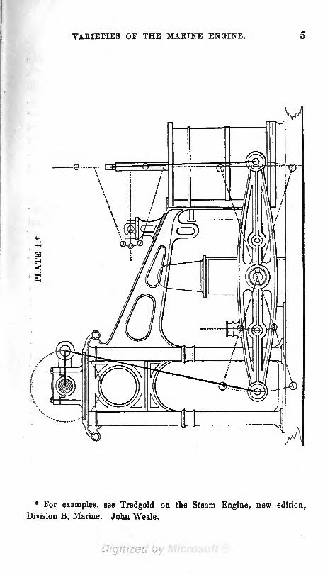
certain cases, and under certain conditions. An exampleof a side-lever engine is given in Plate 1.
TABIETIES OF THE 3IABINE ENGINE.
*
S3
* For examples, see Tredgold on the Steam Engine, new edition,
Division B, Marine. John Weale.

6 GENEBAL DESCRIPTION AND
Disadvantages of the Side-lever Engine. There are two
very important conditions, however, in the economy of a
sea-going steamer which the side-lever engine does not fulfil
namely, lightness of weight, and compactness of form.
As these properties were found to be most essential in the
machinery of a war steamer, it soon became apparent that
some other arrangement of parts must be adopted which
would admit of the same power being stowed in less com-
pass, and a portion of the weight of the machinery saved
for additional coals, or stores, or armament.
Adoption of the Direct-acting Engine. Hence the adapta-tion and general use of direct-acting engines in the Koyal
Navy, by which means (in conjunction with the adoption of
tubular boilers) the length of the engine room was di-
minished by about one third, and the total weight of
machinery by two fifths. It may be observed here, that the
weight usually allowed for side-lever engines, flue boilers
with water, and paddle wheels, is one ton per horse power ;
whilst direct-acting engines with tubular boilers and water,
paddle wheels, &c., scarcely exceed 12 cwt. per horse power.The distinguishing feature of all direct-acting engines con-
sists in the connecting rod being led at once from the head
of the piston rod to the crank without the intervention of
side levers : and as it happens (unfortunately, we think)
that this kind of engine is capable of almost endless variety,
each manufacturing engineer has introduced his own child
into the steam navy, where scarcely two pairs of direct-
acting engines are to be found alike.
Varieties of the Direct-acting Engine. These may be all
classed under three heads; namely, those which obtain the
parallelism of the piston rod by means of the system of
jointed rods called a "parallel motion;" those which use
guides or sliding surfaces for this purpose ;and those de-
nominated "oscillating engines," in which the cylinder is

VABIETIES OF THE MABINE ENGINE. 7
hung upon pivots and follows the oscillations of the crank.
Belonging to the first class are those of Seaward, Hennie,
Fairbairn, Forrester: and to the second class, Maudslay,
Miller, Fawcett, Boulton and Watt, Bury, Robert Napier,
Joyce, &c. As these various arrangements cannot be ren-
dered intelligible in words, sketches of some of the most
characteristic are subjoined, in Plates 2, 3, 4, 5, 6, and 7.
PLATE II.
Direct-actiny Engine, as constructed by MESSRS. SEAWARD,CAPEL & Co.*
* See pages 8 and 9 ; and for full details of the engines of the Cyclops
see the Appendices to Tredgold. John Weale.

PLATE III.
I
Direct-Acting Engine of 500 H. P. of H. M. S. Bull-Dog, constructed
by MESSRS. RENNIE.

VARIETIES OF THE MAEIITE ENGINE.
PLATE IV.
End Elevation of Engines of H. M. S. Cyclops.
PLATE V.
Elevation of Main- lever of Parallel Motion ofH. M. S. Cyclopg.

10 YABIETIES OF THE MABINE ENGINE.

VARIETIES OF THE MARINE ENGINE.

12
PLATE VIII.
Marine Engine of the Rainbow Iron Steam Vessel, constructed by
MESSRS. FORRESTER & Co., Liverpool. See Appendices to Tredyold..Tnn

YABIETIES OF THE MAEINE EJfGISE. 13
Shortness of Stroke a Defect. The unavoidable shortness
of the stroke and of the connecting rod in the majority of
direct-acting engines is certainly a defect, and becomes
sensible in practice by the increased wear and tear of
brasses and packings, and a greater consumption of tallow
and oil when compared with the old side-lever engines.
Several of the direct-acting varieties, it is true, are not ne-
cessarily confined in the length of stroke as, for instance,
the "steeple engine," which is such a favourite on the
Clyde.
Steeple Engine. The latter derives its name from the
high erection on deck required by the guide to the connect-
ing rod, which works above the crank shaft, and can be
recommended only in the case of river steamers where the
increased height of the centre of gravity, and the increased
surface exposed on deck to the action of the winds and the
waves, are not so detrimental as would be the case in a sea-
going steamer. See page 12, a successful example. She
made, notwithstanding, very rapid passages between Lon-
don and Antwerp.
Double-cylinder Engine Maudslay and Field's double-
cylinder variety also makes a good engine, and may have a
tolerably long stroke and connecting rod, but for small
powers it is heavy and expensive. It also occupies more
space in the engine room than several other kinds of direct-
acting engines ; but for very large powers, where the
excessive diameter of a single cylinder may be considered
objectionable, it appears to be most applicable, and has in-
deed proved itself to be highly efficient. See Plate 9.

H GETTEEAL DESCBIPTIOtf AND
PLATE IX.
Direct-acting Double-cylinder Enyine as constructed ly
MESSRS. MAUDSLAY, SONS & FIELD.*
* See Tredgold on the Steam Engine, new edition, Division B, Marine
Engines. John Weale.

YAEIETIES OF THE MAIUNE EXCISE. 15
Oscillating Engine. Of all the direct kinds, however,
the oscillating engine, which has derived from Mr. Penn
so much of its elegant simplicity and present perfection
of workmanship and arrangement, is generally preferred.
It need hardly be explained that this engine derives its
name from the fact of the cylinders "oscillating" uponhollowaxes or "trunnions," through which the steam is ad-
mitted to, and withdrawn from, the valves the piston rod
by this means accommodating itself to the motion of the
crank without any"parallel motion" being required. This
construction has now been proved as applicable to ocean
steamers as to the small boats on the Thames, where it has
long been a favourite;and it appears to be also well
adapted for driving the screw propeller. See Plate 10.
PLATE X.
/Tail IPIPII ID I V
Oscillating Engine as constructed by MESSRS. JOHN PENN & SON.*
* See Tredgold on the Steam Engine, new edition, Division B, Marine
Engines. John Weale.

16 GENEBAL DESCRIPTION AND
Machinery for Propulsion by the Screw. The introduction
of the new mode of propulsion by the screw has created the
necessity for new modifications of the marine engine ;and
as it is essential for the due performance of the screw pro-
peller that it should revolve with a considerable velocity, it
has been deemed necessary to employ gearing or straps, in
many instances, to multiply the speed of the engines. The
use of toothed gearing being objectionable, however, in sea-
going vessels, from the liability of the teeth to be stripped
or deranged by sudden shocks received by the screw in a
rough sea, it is preferred to attach the engines directly to
the screw shaft in all cases where the required speed of the
screw renders this practicable. This can be readily accom-
plished when a great speed is not expected from the vessel,
as in the case of auxiliary steam power ;or where a long
pitch in the screw, and a moderately short stroke in the en-
gine, permit the requisite number of revolutions. For it
is evident that the piston in an engine having a three-feet
stroke will make twice the number of reciprocations perminute that it does in an engine with a six-feet stroke, sup-
posing the actual speed of the piston to be the same in each
case. Hence it is usual to subdivide the power of large
screw engines amongst a number of small cylinders, all at-
tached directly to the same screw shaft, and making short
and frequent strokes. "Where gearing cannot be dispensed
with, toothed wheels are preferable to straps.
Internal Gearing. "With the view of affording additional
security against accident, Mr. Eairbairn has introduced into
a large pair of screw engines for the Eoyal Navy a system of
internal gearing, where the small pinion on the screw shaft
is driven by teeth on the internal periphery of the driving
wheel attached to the engine. The advantage of this plan
consists in the greater number of teeth which are thus
brought into gear at one time, so that the strain is divi-

VARIETIES OP THE MABINE EJfGIXE. 17
ded amongst several, in place of being wholly transmitted
through one tooth.
Protection of the Machinery from an Enemy1
s Shot. So
long as the paddle wheel continued to be the propelling
agent, it was plainly impossible to devise any means bywhich the machinery could be protected from an enemy'sshot ; but the recent adoption of the screw propeller has
facilitated this very desirable object to the navy. For as
the screw itself revolves entirely beneath the surface of the
water, we are now enabled to place all the machinery which
gives it motion under the water line also, (in some cases,
so much as six or eight feet,) by which means it gains a
comparative though not perfect safety. It is well known that
a shot will not penetrate more than a foot or two under
the water unless it meet the surface at a high angle, but
then the bottom of a vessel at sea must be often exposed,
during both the rolling and pitching motion, to a position
considerably beneath the level water line, when an enemy'sshot would have a fair mark at the machinery, although in
smooth water it might be perfectly protected. The addi-
tional security, however, which such machinery does enjoyrenders it a question of the utmost importance to disposethe engines and boilers of a screw-propelled vessel quiteunder the water line. Hence another plea for the practice
of subdividing the power of large engines amongst a numberof small cylinders, these being ranged (generally in a hori-
zontal position) on either side of the screw shaft, so as to
require as little height as possible for the reciprocation of
their moving parts. The boilers are also made as low
as practicable, and if a steam chest be added, provision
should be made for shutting it off from the rest of the
boiler in case of injury, the steam being in that case drawn
directly from the top of the main boiler.

18
CHAPTEE II.
DETAILS OP THE MABINE ENGINE: THEIR PBOPOBTIONS
AND USES.
ALTHOUGH it is not here contemplated to supply rules
and formulae for proportioning the marine engine, a few
remarks are made upon such proportions as the officer in
charge of the engines may be able to alter or modify for
himself if found necessary.
Steam Pipes. The steam pipe from the boiler must not
be too contracted, otherwise the pressure of the steam uponthe piston moving in the cylinder is not kept up duringits stroke, the steam being then what is called "
wire-
drawn" in the pipes. The usual area allowed to the steam
pipe is one square inch per horse power, but this maybe increased with advantage in the case of small engines.
It is of much importance that the pipes should have as
short and direct a route as possible from the boiler to the
engines, with few angular bends or changes of direction,
as all such impediments act most injuriously by checkingthe supply of the steam. Where bends are unavoidable,
they should be made of as large a radius as convenient.
Much care must also be taken to prevent the loss of
heat by radiation, and the consequent condensation of
steam in the pipes, which should therefore be clothed with
sheets of hair felt wrapped round with spun yarn, the
whole being sewn up in canvas, and painted. Copper is
the only material which should be used for steam pipes
between the boiler and engine, as wrought-iron pipes gene-rate scales of rust which, becoming detached, are blown
by the steam into the valves and cylinder, where they do
DETAILS OF THE MAEINE ENGINE, ETC. 19
much mischief by scratching and cutting the surfaces.
When a straight pipe forms the connection with the boiler,
an expansion or "fawcett" joint must be provided, but this
may be dispensed with when an elbow occurs in the length
of pipe.
Throttle Fahv?. The throttle valve of a marine engine is
always worked by hand, and should be used only in control-
ling the speed of the engines for any temporary purpose,such as in passing through a crowded river, before stoppingat a pier, &c., but should seldom or never be used for work-
ing the engines expansively at a permanent reduction of
speed.
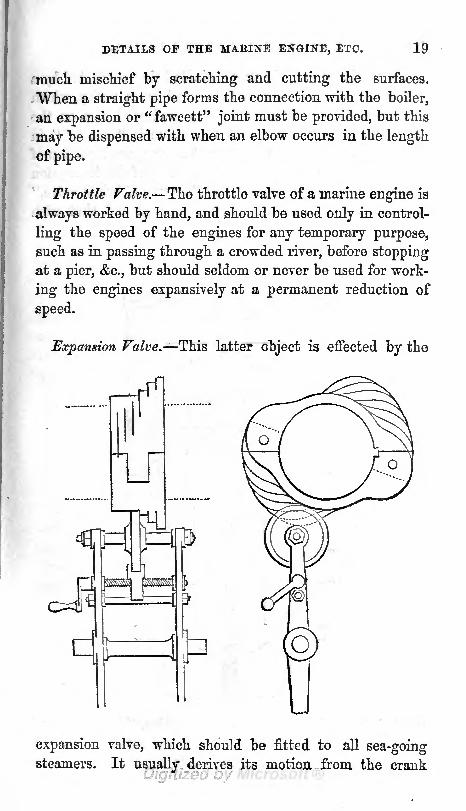
Expansion Valve. This latter object is effected by the
expansion valve, which should be fitted to all sea-goingsteamers. It usually derives its motion, from the crank

20 DETAILS OF THE MARINE ENGINE!
shaft of the engine, the valve spindle being connected by a
series of rods and levers with a small brass pulley, which
presses against the periphery of a graduated cam on the
crank-shaft, by which means the steam is" cut off" in
the most advantageous manner at any required portion of
the stroke. The valve employed is usually of the description
called the " Cornish double-beat," or "equilibrium valve,"
which has the advantage of being opened and shut with
great facility, since, from its construction, the pressure of
the steam has no tendency to jam it against its seat the
objection to which all flat or plate valves are subject. Also

THEIR PROPORTIONS AND USES. 21
by a slight rise of this valve, a very large opening is obtained
for the steam. This will be best understood by reference to
the annexed engraving. The principle on which this valve
is constructed is, that if steam be conducted by a branch
pipe into a larger perpendicular pipe between two common
conical valves placed in it, and connected together by a
centre spindle or rod, and resting on their seats, it would
exert a pressure on the under side of the upper valve, tend-
ing to raise it;and on the upper side of the lower one, tend-
ing to keep it down ;these two pressures in opposite direc-
tions thus neutralizing each other. It is therefore evident
that these two valves form one double-seated valve, and maybe opened in equilibria, by means of their spindle. The steam
then passes up one pipe and down the other, and, if desired,
these pipes may be again immediately united. By the pecu-liar arrangement ofthe seats and partitions, this is done inside
the outer casing of the valve, as shown in the engraving.
Stephenson*s Link Motion applied to give Expansion. Amodification of Stephenson's elegant and simple link motion
for locomotives has been adapted to the marine engine, bywhich means the length of stroke of the cylinder slide valves
may be varied at pleasure, so as themselves to act also as
expansion valves;but as their motion is derived from an
eccentric of the usual form, it has a different character
from that produced by the cam in the former instance; the
admission and exclusion of the steam now taking place more
gradually, and, as is generally admitted, with less effect.
To set the Slide Valves. The manner of setting the cylin-der slide valves so that they shall admit and shut out the
steam from the cylinder at the proper time, independently of
the action of the expansion valves, is a matter of the greatest
importance. The chief points to be attended to are these :
1st, that the steam shall be shut off a little before the end of
the stroke, by closing the aperture of the steam port, whichcauses the piston to be brought gradually to rest without

22 DETAILS OF THE MABINE ENGINE :
jarring tlie engine, independently of the advantage derived
from expanding the stearn; 2nd, that the eduction port, or
the passage to the condenser, should be closed before the
end of the stroke, which is termed "cushioning" the piston,
because it then completes the stroke against an elastic air
cushion, in consequence of a portion of uncondensed vapour
being shut up between the piston and the top or bottom of
the cylinder ; 3rd, that the steam port on the same side of
the piston should be opened a very little before the end of
the stroke, so that the steam may have acquired its full
pressure as soon as the crank shall have turned the centre;
and, 4th, that the communication with the condenser should
also be opened on the opposite side of the piston a little
before the end of the stroke, so as to have a vacuum readymade in the cylinder before the return stroke begins.
of the Valve. Now, if the slide valves had simplyto admit and shut off the steam at each instant that the
piston arrived at the top and bottom of its stroke, the face
of the valve would have exactly the same depth as the aper-
ture to be covered ;but that the steam may be cut off a
little before these points, it is necessary that the valve faces
should be made deeper towards that side from which the
steam comes, so that after closing the steam ports they maymove past the aperture for a certain space at each end of
the stroke. This space, which they lap over the valve seat-
ing, is called the "lap" or "cover" of the valve on the
steam side. It is apparent that no lap is necessarily re-
quired on the exhaust side, because we want the communi-
cation with the condenser to open before the end of the
stroke. The general practice on this point is to make the
edges of the yalve faces Hush with the edges of the cylinder
ports, when the valves are placed exactly in the middle of
their stroke. The objection to lap on the eduction side is
that the communication between the cylinder and the con-
denser will be closed too early, and the effect termed cush-
ioning will take place to an injurious extent. The uncon-

THEIE PBOPOBTIONS AND TJSES. 23
clensed vapour is compressed sometimes even to sucli an
extent as to exceed in pressure the steam in the boiler, and
an erroneous opinion has then been formed in examining
the lead corner of an indicator diagram that the valve has
been set to open too soon. In these cases after due exami-
nation the cover on the eduction side should be cut off.
By means of the lap, therefore, we are enabled to shut
out the steam, and to open the passage to the condenser
before the end of the stroke. But it is also necessary that
the port should open to steam on the opposite side before
the commencement of the return stroke.
"Lead" of the Valve. Steam is admitted to act upon the
piston before it has quite completed its stroke, by giving
the valve a motion in advance of the crank. The extent to
which the port may be open for the admission of steam,
when the engine is on its top or bottom centre, is varied
much, but an allowance of one square inch of opening to
every sixteen horses' nominal power, will be found to give
good results. In all engines where the velocity of the
piston is greater, the lead may be increased beyond this
extent with advantage. With common slide valves driven
by an eccentric great breadth of port is evidently desirable,
as a slight motion of the valve then gives at once a greater
area of opening..
Reversing the Engines. If marine engines were requiredto work only in one direction, the eccentric pulley mightthen be permanently fixed on the paddle shaft, (as it is on
the fly shaft of a land engine,) in the most advantageous
position for lead, &c.;but as a steamer must be equally ca-
pable of reversing the motion of the wheels, such an ar-
rangement becomes unsuitable. For let us suppose that
the engine has been stopped at half stroke in the usual
way, by throwing the eccentric out of gear and shutting off
the steam, and that steam has been admitted by hand to
the opposite side of the piston, the shaft will then com-
mence revolving in the opposite direction. But it is evi-

24 DETAILS OF THE MA.BIKE ENGINE:
dent that before the engine can be thus put into the proper
position for enabling the eccentric to continue the reversing
motion, the shaft must be free to rotate backwards within
the eccentric pulley through half a revolution. Hence a
necessity arises for placing the eccentric pulley loose uponthe paddle shaft, the latter being fitted with a "
stop"
or"snug," with which another "
stop"cast on the pulley comes
into contact after halfa revolution in either direction, and thus
communicates motion to the valves with perfect indifference
as to which end of the eccentric stop may be in contact.
Expanding oy Means of the Lap on the Slide Valves. It is
apparent that the lap of the slide valve presents a simplemethod of working the steam expansively to a small thoughdefinite extent, which is then fixed beyond the power of
alteration until the valves are reset. The amount of ex-
pansion which can be thus given, is limited by the effect
produced upon the eduction port as before mentioned. It
is, however, objectionable to carry expansion by this means
to the full extent to which it is practicable, from the fact
that when the vessel is placed in the most difficult cir-
cumstances, struggling off a lee shore, with the speed of
herengines reduced by a head wind, so that there is an
abundant supply of steam, there are then no means of com-
pletely filling the cylinders, and the full amount of power
capable of being generated cannot be realized. The most
beneficial practice therefore, when the common slide valves
are used, is to have only a small amount of lap, so that it
may be possible to obtain the utmost power that the engines
are capable of exerting at such times as it may be essential,
and to have an additional valve for regulating the amount
of expansion to such extent as may be desired. The latter
system is in accordance with the growing intelligence of
those now generally entrusted with the working of marine
steam engines. An excessive and wasteful expenditure of
steam under circumstances when a corresponding result
cannot be obtained from it need not be feared with a good
superintending engineer on board, as so much interest has

THEIR PROPORTIONS AND USES. 25
of late been excited not only amongst those parties, but also
amongst commanding officers, on this most important point.
Blow-through Valve. Before the engines can be started
it is necessary that the air should first be expelled from the
cylinder, condenser, and air pump, and its place supplied
by steam, in order that we may obtain a vacuum by its
subsequent condensation. Hence a valve, called from its
office the "Blow-through valve," is provided to open a
temporary communication between the steam in the valve
casing and the condenser, by which means a rush of steam
is caused to pass through the internal parts of the engine.
This operation is continued until the steam begins to issue,
hot and transparent, from another valve on the condenser,
called the "Snifting valve," situated at the opposite pointfrom where the steam entered. These valves are of course
closed as soon as the engine is set to work.
Clothing the Cylinders, Sfc. As it is of much importancethat the internal heat of the cylinders and valve casings
should be preserved from radiation (especially when highsteam is used expansively) these must be carefully clothed
with felt and dry timber, bound round with metal hoops.
Clearance of the Piston. The "clearance"
of the pistonat the top and bottom of the stroke should be just as little
as is consistent with safety, and is usually made from one
half-inch to five eighths or three fourths of an inch,
Priming Valves. "Escape" or "Priming valves" are now
generally fitted to the top and bottom of the cylinder, to
permit the escape of water without danger to the machineryfrom the shock of the piston against the incompressible
fluid. This water collects partly from the condensation of
steam within the cylinder, but is chiefly carried over from
the boiler, either as "priming," or in a state of mechanical
suspension with the steam. It may also overflow throughthe valves from the condenser. These valves should be
C

26 DETAILS OF THE MABINE ENGINE:
fitted "with hoods to carry off the ejected water into the
bilge, and prevent its being thrown about the engine room.
PacJdng for the Piston. Metallic packing is now univer-
sally employed for the pistons of marine engines, this being
made in the form of cast-iron rings, either possessed (from
their construction) of elasticity in themselves, or deriving
it from steel springs placed behind them. The cast-iron
rings, unfortunately, lose their elasticity after being some
time in use, in which case they must be taken out, and have
this restored by hammering and thereby elongating their
internal surface; or else steel springs must be added to
press them out against the cylinder, when they are cut into
segments to allow the springs greater freedom of action.
The piston is lubricated with melted tallow through a
grease cock on the cylinder cover, advantage being taken
of the vacuum during the up-stroke to suck in the tallow.
The grease-cock aperture also serves for applying the
"Indicator" during the stroke above the piston.
Condenser. The condenser should have a capacity of
half the cylinder as a minimum, but may be made larger
with advantage. The size should depend, to a certain extent,
upon the temperature or density of the steam used, as plentyof room should be allowed for high steam to expand into
low-pressure steam before being condensed, if this has not
been, previously effected by expansion within the cylinder.
Injection Valve. The area of the injection valve should
be about one square inch for every ten-horse power. This
is an ample allowance in all cases, and is more than neces-
sary when the injection water has a temperature of 52
Pahr. (which is the average for our seas), though in tropical
climates it will not be found too much. The average tem-
perature of the Mediterranean is about 65; at 20 of
latitude, about 75: and at the equator, about 82, Pahren-
heit. The supply inay be regulated at will by the opening

THEIK PBOPOBTIONS AND USES. 27
given to the valve, as shown on an index plate. It is better
in the case of large engines to have two injection cocks
fitted between the sea and each condenser one, the sea
cock, close to the side of the vessel, as a security in case
of injury to the internal pipe, and the other upon the con-
denser. Besides these, it is usual to have an injection pipe
led from the bilge of the vessel, so that in case of unusual
leakage the sea cock may be closed, and the engine sup-
plied with injection from this source. The mouth of this
pipe should be carefully guarded and kept clean, as whenthe emergency arrives for its use it has too often been
found choked up and unserviceable.
Temperature of the Condenser. The process of condensa-
tion will be the more complete in proportion to the cold-
ness and quantity of the injection water, the manner in
which it is brought into contact with the steam, and the
temperature of the steam itself on entering the condenser.
The resulting temperature which is usually aimed at by
engineers for the condenser is from 90 to 1 10. The limit
to a more perfect degree of condensation is imposed by the
increased size of the air pump required to withdraw the
additional injection water, which diminishes the work and
increases the cost of the eDgine. Hence the engineer i
well satisfied if the temperature of the condenser be not
above 110, with which a vacuum of 27i or 28 inches of
mercury is obtained by a good engine.
Elasticity of Watery Vapour at different Temperatures.
According to Dr, lire's experiments, uncondensed watery
vapour at a temperature of 100 balances 1'86 inch of
mercury ; at 110, 2'45 inches; at 120, 3'3 inches; at 130,4-366 inches
;at 140, 5'77 inches; and at 150, 7'53 inches
ofmercury, or exerts a pressure of 3? pounds per square inch.
Flow of the Injection Water. The Telocity at which
injection water enters the condenser varies as the squareC2

28 DETAILS OF THE MABINE ENGINE :
root of the pressure, and will be about 40 feet per second for
the full pressure of the atmosphere against a pure vacuum.
The sea injection should be taken from about mid-way be-
tween the surface of the water and the bottom of the vessel,
so as neither to draw impurities from the surface, nor be
liable to become choked with sand or mud from the bottom,
when working in shallow water, or when the vessel is
aground. In many of the latter cases, the engines have been
rendered useless at the time when most needed, by sand
being sucked in and destroying the action of the air pump.
Barometer Gauge. A barometer gauge is attached to the
condenser to show the vacuum. It is usually constructed
like a common barometer, except that the top of the glass
tube communicates through a small pipe and cock with the
interior of the condenser, the partial vacuum of which then
takes the place of the Torricellian vacuum of the ordinarybarometer. The surface of the column of mercury in this
case indicates the difference which exists between the pres-
sure of the atmosphere and the pressure in the condenser,
so that if we see a column of 27 inches of mercury sup-
ported in the tube, and the pressure of the atmosphere at
that time be 30 inches of mercury, we know that there is
a pressure of three inches of mercury, or 1 Ib. on the
square inch within the condenser.
Sources of Error. As we find by the common barometer
that the pressure of the atmosphere is constantly varying,
a correction should be made for this in estimating the va-
cuum of the condenser. Another source of error arises
from the varying level of the mercury in the open cup
which supplies the gauge tube, according as the tube be-
comes more or less filled;since it is evident that only that
portion of the column which rises above the surface of the
mercury in the cup can be reckoned as the counterpoise to
the atmosphere. The simplest manner of alleviating the last-
mentioned source of error is to make the surface of mer-

T1IEIB PEOPUilTIONS ASD USES. 29
cury m the cup very large in comparison with the bore of
the tube. As the barometer gauge is very often found to
show incorrect results (either through ignorance or design
on the part of the foreman who saw it fitted) it would be
well if every commander of a steam vessel satisfied him-
self of its accuracy, before giving credence to such wondera
about vacuum as are sometimes published to the world.
Improved Barometer for the Condenser. Subjoined is a
sketch of an improved barometer for the condenser, which
has been tried and found useful. A glass syphon tube,
a a, 34 or 35 inches long, is half filled with mercury ; one
end at b being left open to the atmosphere, which is ad-
mitted through a very small aperture to exclude the
dust. A sliding brass scale, graduated from at the bottom
to 30 inches at the top, is fitted in
the space between the two legs of c
the inverted syphon. When requiredto show the vacuum, the zero point
of the scale must be shifted to where
the mercury falls in the leg open to
the atmosphere, and the height of
the mercury in the other leg beingthen read off from the scale, the exact
difference of height between the two
columns is thus obtained. This baro-
meter posesses also the advantagethat the mercury cannot be blown
out by a slight pressure of steam in
the condenser (as is the case with
the common barometer), which ad-
mits of its being kept in constant
use as a guide to the engineers in
stopping and starting their enginesin any time of difficulty. The sy-
phon may be made, if preferred, by uniting two straight
glass tubes in a short piece of bent iron pipe.
CONDENSESw

30 DETAILS OF THE MARINE ENGINE:
Evih arising from the Use of Sea Water for Confirmation.
" The use of sea water for condensing the steam and sub-
sequently feeding the boilers, entails upon marine engines
the necessity for ejecting, or"blowing off'* a portion of the
saturated water, at intervals, into the sea, to prevent the
deposition of scale and salt, and causes the loss of a con-
siderable quantity of caloric. The specific gravity of the salt
water in the boiler, taken at a medium degree of saturation,
is about one-tenth part greater than that of fresh water ;
and as the capacity of the water spaces requires to be in-
creased to allow for cleaning, as well as for the more ready
escape of the steam through the denser fluid, we may add
about one fifth for the extra weight of salt water in the
boiler as compared with fresh, taking into account the
portion which is blown off. When we consider also the
very rapid wear of boilers using salt water, it is at once ap-
parent that an efficient means of supplying them with fresh
water at sea is one of the greatest desiderata in marine
engineering.
Surface Condensation attempted. With this view, manyattempts have been made to condense the steam by con-
tact with cold metallic surfaces, instead of by the plan of
injecting amongst it a large body of salt water from the sea.
Could this be done effectively, the boiler might then be fed,
during the whole voyage, with the fresh water which it had
at starting ; the same water, after circulating through the
cylinder as steam, being condensed without intermixture
with other water in the condenser, and then returned to the
boiler to be again formed into steam, being thus kept in a
continuous round of action.
Surface Condensation found to be Inefficient. But, unfor-
tunately, the principle of surface condensation has hitherto
always proved inefficient. The difficulty has generally been
to present a sufficiently large cooling surface to the steam,
so as to produce a rapid condensation,

THEIR PEOPOETIONS AND USES. 31
Halts Condensers. This cannot be urged against Hall's
Condensers, however, in which the steam is passed through
many miles of little copper pipes enclosed in a cistern of
cold water, which is constantly renewed from the sea bymeans of a force pump worked by the engine, but in this
case the small pipes through which the steam is passed are
liable to become "furred" on the outside, or choked up al-
together by deposits from the sea water. Besides this, the
additional machinery required adds so much to the expense
and intricacy of the engine, as well as to its weight and the
space it occupies in the vessel, that this condensing appara-
tus has not been found applicable in practice. In such an
arrangement the loss of steam arising from leakage, or from
blowing off at the valves, is compensated to the boiler bythe use of a small apparatus for distilling sea water. The
air pump is then, of course, much reduced in size, as it has
no injection water to remove.
Air Pump. The capacity of the air pump is usually pro-
portioned to the cylinder as 1:8, or thereabouts;and the
delivery valve has an area of one third of the air pump,
though the orifice through the ship side for the escape of
water from the hot well need not be more than one sixth of
the area of the air pump, when the latter is single-acting.
In large engines, a sluice valve is usually fitted inside the
vessel across the mouth of the discharge pipe at the ship
side, which being closed by hand when the engines are not
working prevents the wash of the sea from entering the
hot welL
Feed Pumps. The feed pumps supply to the boiler so
much of the water which has been used in condensing the
steam as will restore the waste from evaporation and blow-
ing-off, and each of the two feed pumps which are usuallyfitted up is made sufficiently large to supply all the boilers in
case of accident to the other pump, or to its feedpipes. The

32 DETAILS OF THE MAEINE ENGINE, ETC.
necessary quantity to be admitted to the boiler is judged of
by observing the level in the glass water gauge, and is regu-lated by hand by means of the feed cock on each boiler
the surplus water, which is rejected by the boiler, being
expelled into the sea by the feed pump through a loaded
escape valve.
Bilge Pumps. Bilge pumps are fitted to marine enginesas a security to the ship in case of extraordinary leakage, as
well as to save the work of the crew in pumping the hold
dry. The bilge pipes should be made of lead, which suffers
less corrosion than copper from the acidulous bilge water of
wooden ships, and care must be taken that they do not getchoked with filth.
Hand Pump connected with the Engines. A hand pumpmust also be fitted for the purpose of feeding the boilers
while the engines are at rest and the steam blowing off.
This is made capable of being connected to and driven bythe engines, so as either to assist in feeding the boilers, if
necessary ;to act as a fire engine in case of need
;or for the
every-day duty of washing decks. It should also be so ar-
ranged that it may draw either from the sea or the bilge.
Hand Pump driven by a Supplementary Engine. In the
case of vessels with tubular boilers this pump usually receives
its motion from a small high-pressure engine (technically
known as " the donkey") which works by the pressure of
steam in the large boilers. Such a provision becomes ne-
cessary on account of the rapid evaporation of tubular
boilers in comparison with their confined area at the water
level;but in the case of flue boilers, where the water sur-
face is comparatively larger, and danger from the water
level falling too low during a temporary stoppage is there-
fore diminished, this pump is generally worked by hand
only.

CHAPTER III.
THE MARINE BOILER : ITS GENERAL PROPORTIONS, AND
THE PRINCIPLES CONCEBNED IN ITS OPERATION.
The Marine Boiler. The Marine Boiler differs from one
on shore in. this essential particular, that, in the former, the
fire and flues are wholly contained within the boiler itself,
and are surrounded with water in every direction, such
an arrangement being rendered necessary as a precaution
against fire. There are several varieties of this boiler in
use, designated the Flue boiler, the Tubular boiler, the
Sheet-water-space boiler, &c.
Flue Boiler. In the Flue boiler, the flame and hot gases
generated in the furnace are confined in narrow flues, which
wind about amongst the water of the boiler until the heat
of their contents has been nearly all absorbed;after which,
the flues are gathered together into the "up-take," at the
bottom of the chimney.
Form of the Flues. They should be so roomy as to allow
of a boy getting readily through them to clean out any
deposit of soot or ashes;but their area must not be unduly
increased in any one place, so as to check the velocity of
the draft, as in that case a deposition of soot and ashes
invariably takes place, by which the heating surface is not
only impaired, but the plates are corroded and destroyed.
Arrangement of the Heating Surface. It is a point of the
utmost importance that no part of the heating surface of a
boiler should be so situated that the steam may not readily
C3

THE MAEIKE 330ILEB:
rise from it, and escape to the surface of the water;sinco
the plate, if left in contact with -steam instead of water,
becomes unduly heated and destroyed, and an explosion
frequently ensues.
Horizontal Heating Surface the best. It is found in prac-
tice that a perpendicular heating surface, such as the sides
of rectangular flues, is by no means so efficient for raising
steam as an equal area of horizontal surface, such as the
tops of the same flues or of the furnaces. The reason of
this is sufficiently apparent ;for the steam in the first case,
rising perpendicularly from every portion of the surface,
forms a film or stratum of vapour in contact with the sides
of the flue, which prevents the free access of the water to
the hot metal -
3 but, in the other case, the steam leaves the
iron as soon as it is generated, and allows the water to be
constantly in contact.
Bottom Heating Surface inefficient. From the same cause
of imperfect contact, the flat bottom of a metal flue is veryinefficient as heating surface
;and plates thus disposed are
found to wear out much quicker than those forming the
tops of flues or fire boxes. The plan of covering the bottom
of the flues with a non-conducting material, as bricks or
cement, has been found to cause hardly any diminution in
the evaporative power of the boiler, and is by some thoughtto increase the durability of the bottom plates.
The objection to this plan is, that from the unequal de-
grees of expansion between the iron and the non-conducting
lining, it is impossible to maintain an unbroken joint be-
tween their surfaces, so that a space is formed in which
brine may collect in contact with the plates, and thus do
more mischief than the original disease.
The flues generally increase a little in height as theyrecede from the furnaces, in order that the depth of water

GENERAL PROPORTIONS AND OPERATION. 35
over them may be less in proportion as the contained air is
cooler.
Disadvantages of Flue Boilers. Although flue boilers
occupy at least one third more space in the vessel than
tubular boilers of an equal evaporative power, and are
nearly one third heavier, they are still preferred in some
instances (as on board the "West India mail packets), as
being more economical both with regard to first cost, re-
pairs, and durability. It is hardly believed, however, that
these qualities, if really possessed, are not more than coun-
terbalanced by the increased consumption of fuel neces-
sarily attending any increase in the displacement of the
vessel, as well as in the loss of so much valuable space for
passengers, goods, or stores.
Tubular Boilers. In tubular marine boilers, the flame
and hot gases from the furnaces are led through a greatnumber of small tubes (of iron or brass), completely sur-
rounded with water, to the flue or "up-take" at the bottom
of the chimney. By this arrangement we are enabled to
condense a very large amount of "heating surface" within
a comparatively small space; and in consequence of the
extreme subdivision of the heated gases in passing throughseveral hundreds of tubes not above three inches in dia-
meter, every particle of them is brought into contact with
the absorbent surface, and their caloric is thus extracted
in the smallest possible time.
Furnaces. The furnaces, or "fire boxes," should be so
deep as to allow of a roomy ash-pit under the doors, the
front of the grate bars being fixed at a height of about
30 inches above the firing stage, and sloping down with aninclination of about two inches to the foot towards the"bridge."

3G THE MATJINE BOILEft :
Fire Bars. The bars are best made of wrought iron in
several lengths of about 30 inches each, to suit the lengthof the furnace, which should not exceed 6| to 7 feet. Thebars may be made from five eighths to three quarters of an
inch thick on the top edge, about three inches deep, and
may have from three eighths to seven sixteenths of an inch
of air space between each for Welsh coal, though these
dimensions should be modified according to the nature of
the fuel it is intended to burn. No open space should be
left between the outer bars and the sides of the furnace, as
it is expedient to check the formation of flame at that part,
in order to protect the plates from being" burnt."
The direct Impact of Flame to be avoided. It should be
borne in mind that the direct impact of flame is very muchhotter than radiant heat, and the plates of a boiler should
be protected from it as much as possible. This forms a
source of objection to many of the plans which have been
proposed, or adopted, for burning the inflammable gases
in the flues of a marine boiler by the admission of a jet of
air, which too often acts like a blow-pipe by directing the
flame thus generated against the plates.
The Bridge. The "Bridge," to which we have alluded,
crosses the back of the furnace to support the ends of the
fire-bars, and prevent the fuel being carried into the flues,
and also tends to cause the flame to reverberate upon the
roof of the furnace, although the construction of the boiler
sometimes does not require it at all. It is either formed
of fire-brick, or else constitutes a part of the boiler by
being made hollow, and containing water, in which case
the top of the bridge inclines at a considerable angle to
allow the escape of steam.
Wafer Spaces. The furnaces should be covered with 1-4
or 15 inches of water, and the tubes or flues with 10 or

GENERAL PROPORTIONS AND OPERATION. 37
12 inches, in the case of sea-going steamers. The water
spaces between the furnaces are usually five to six inches
wide; and between the flues, four to five inches. The
spaces between the crowns of the furnaces and the bottoms
of the tubes should be not less than 10 inches, to allow of
a " man-hole" between the arched tops. The bottom water
spaces should be not less than eight inches, to allow room
for "scaling" and cleaning. It is usual to allow a space of
one inch between the tubes of a tubular boiler, these being
arranged in perpendicular rows, one over the other, bywhich means the steam is supposed to escape more readily
than when they are placed zig-zag.
Although many of the proportions here set down are
beyond the control of the officers in charge of a steam
vessel, still we think it expedient to state, in as few words
as possible, what proportions of engine and boiler are con-
sidered by practical men to be most conducive to perfect
efficiency. For unless a general knowledge of these pro-
portions be acquired, it is plainly impossible to form a
judgment as to whether any observed deficiency in the
work of the engines is due to the fault of their original
construction, or depends upon those details <& managementwhich it is more particularly our present object to explain.
And although it is but just to the talented constructing
engineers of this country to assume, that in the majorityof cases the machinery of a steam vessel leaves their hands
in a perfect state, it is nevertheless most satisfactory to
be enabled to prove this for one's self.
Requisite Amount of Heating Surface. Before we can
obtain a good average result from the combustion of the
fuel, it is necessary that the boiler should present about
twelve square feet of effective heating surface per horso
power ;for if less surface than this be given, a wasteful
quantity of heat escapes up the chimney, from not havingbeen absorbed by the water. "What is termed "effective"

38 THE MAEINE BOILER :
heating surface, must be calculated independently of the
bottoms of flues and fire-boxes, and of one fourth part of
the whole tube surface. The grate-bar surface should be
at least 80 square inches per horse power, and, where practi-
cable, may be increased to 100 square inches with much
advantage.
Areas of Flues and Tubes. The area of the first flue, or
the clear area through the tubes, should equal one sixth of
the grate-bar surface led into them;and the area of the
flues may be gradually diminished from the fires to the
chimney by one fourth part.
A Roomy Furnace desirable. As a large furnace is found
by experience greatly to facilitate the admixture of the
gases, and to ensure their more perfect combustion, as well
as to afford the most effective kind of heating surface, it is
of great importance that there should be plenty of room
over the fires.
Combustion checked by the Carbonic Acid. The carbonic-
acid gas which results from the combustion of solid carbon,
has a most injurious effect in checking combustion within
the furnace, for we find by experiment that flame is barely
supported in a mixture of one part of this gas with four of
atmospheric air. Hence the necessity for admitting into
the furnace at least twice the amount of air chemically
required ;and even then, if we analyze the contents of the
chimney, we shall find from one fourth to one-half of the
oxygen which entered the fire still free and uncoinbined,
mixed up with the products of combustion.
Loss of Heat attending the Combustion of the InflammableGases. Now, as the whole of the air thus supplied iu
excess must be heated to a very high temperature before
the combustion of the inflammable gases in the furnace

GENERAL PEOrORTIOJTS AND OPERATION. 39
can ensue, jnucli heat is thus unavoidably wasted so
much, indeed, that it is now well ascertained that the
evaporative value of a bituminous coal producing a large
quantity of gaseous matter is very little, if at all, superior
to the evaporative value of the same coal after being coked ;
the heat generated by the combustion of its volatile pro-
ducts proving, in practice, to be little more than that ex-
pended in volatilizing them, and in heating the surplus air
required for their subsequent combustion.
Formation of Carbonic Oxide. When a stinted supply of
oxygen is furnished to the incandescent fuel on the bars,
an imperfectly oxygenated carbonic-acid gas, named "car-
bonic oxide," is partly produced, accompanied by a corre-
sponding loss in the heat generated during combustion.
As this gas is inflammable, and that at a comparativelylow temperature, it may be burnt in the furnace, or flues,
by the admission of a further supply of atmospheric air
otherwise, it escapes unconsumed up the chimney, where
it may be often seen burning at the top, having caughtfire upon coming into contact with the oxygen of the air.
Although it may be beneficial to consume this carbonic-
oxide, when once formed, by admitting fresh air into the
flues behind the bridge, it is certainly preferable to pre-vent its formation altogether by using a large grate surface,
a thin fire, and plenty of air space between the bars.
Smoke-burning Apparatus. Notwithstanding all that has
been done and written with reference to the so-called" smoke -
burning" apparatus, it is the opinion of those
most capable of forming a correct judgment on this subject,that by a proper construction of the furnace, and a skilful
management of the fire, the smoke and gases may be as
effectually, and certainly more safely, consumed, by admit-
ting the requisite quantity of air for this purpose at once
through the grate bars.

<R> THE MARINE 130ILETI :
Recapitulation. It may be gathered from the preceding
remarks, that some of the most important requisites to
ensure efficiency in a steam boiler are the following :
1st. That the boiler should be designed with a sufficient
amount of heating surface, so contrived that as little of it
as possible may be rendered ineffective, either from the
retention of steam in contact with it, from the formation of
scale within, or from the deposition of soot and ashes in
the bottoms of the flues and tubes. 2nd. That the fire-
bar surface should be sufficiently large to admit of the
necessary quantity of coal being consumed with thin and
open fires. 3rd. That the proper area be maintained
through the flues or tubes, and that the passage to the
chimney be such that the draft may not be interrupted.
4th. That the furnace should be roomy ;the bars thin,
with plenty of air-space between them; and, that the firea
should not be longer than can be conveniently stoked.
And, 5th (which is, perhaps, the most important requisite
of all, and the one most neglected), That experienced and
careful fire-men be provided.
Clothing Marine Boilers, found to be sometimes preju-
dicial. Although it must be admitted that the practice of
"clothing" marine boilers with non-conducting materials,
such as hair-felt, wood, &c., is in all cases highly beneficial
for the production of steam; yet this is alleged to have
induced, in some instances, a rapid wear in the plates of
the boiler. This corrosion is most apparent in boilers
which are frequently used and disused alternately, and
takes place on the interior surface, attacking principally
the top of the boiler and the steam chest. It is, probably,
owing to the alternate wetting and drying of the plates,
which causes the rust to scale off, and thus present a fresh
surface for corrosion each time that the water is blown out
of the boiler. In the case of an unclothed boiler, on the
other hand, the internal surface is scarcely ever "quite dry,"

GENERAL PROPORTIONS AND OPERATION. 41
from the evaporation being checked by tfce low tempera-
ture, and the consequent saturation of the enclosed air.
Marine boilers which are constantly in use, or which make
long voyages only, do not experience this destructive cor-
rosion of the steam chests to the same extent.
Bedding of Marine Boilers. The manner of bedding ma-
rine boilers is a point of some importance, as it materially
affects the durability of the bottom plates. The usual
method adopted by the Admiralty, is to form a close plat-
form of timber over the keelsons, upon which is spread a
plaster of cement, or mastic, about one inch thick, on
which the boiler is set. As this becomes quite hard, it
prevents the bilge-water (which in wooden ships is highly
acid) from washing up to and corroding the plates ;and it
is also intended to stop any leaks which may break out in
the bottom of the boiler, as well as to strengthen it in the
event of an unusually rapid corrosion taking place from
the inside. Unfortunately, however, it is impossible to
preserve a close contact between the iron and the cement,
on account of their different degrees of expansion by heat,
so that when a leak does take place in the boiler, it extends
itself for a large space between the two surfaces, and the
corrosion is increased instead of diminished. Perhaps the
best practice is to rest the boiler on saddles of cast-iron
fixed on the boiler bearers, which leaves the bottom exposedfor examination and painting, and even for small repairs if
necessary. In this case the bottom of the vessel underthe boilers must be kept quite clean and dry by the bilge-
pumps.
Galvanic Action, It is necessary, both in marine enginesand boilers, to guard against the destructive effects of gal-vanic action, which ensue in all cases where two metala
of different degrees of solubility (or possessing different
degrees of affinity for oxygen) are placed in juxtaposition ;

42 THE MAEINE BOILEB, ETC.
as, for instance, iron and brass, when the former metal
suffers a rapid corrosion from being the more oxidable of
the two, while the brass is quite protected.
Copper Boilers. In cases where the frequent renewal of
boilers is attended with great expense and inconvenience,
they are sometimes made of copper, which lasts about four
times as long as iron. Their first cost, however, is about
five times greater for boilers of the same weight, and cop-
per is only three fifths of the strength of iron when cold,
or less than half its strength at 500 Fahrenheit. Iron, on
the contrary, increases in strength from 32 to 550, whenits strength is believed to be at a maximum. It is evident,
however, that although a copper boiler is not so strong as
a new iron one of the same weight, it retains its original
strength unimpaired for a long time, whilst the iron boiler
is every day becoming weaker by corrosion. An iron boiler,
when new, has thus a great superabundance of strength,
to allow for the wearing of the plates by use ;and it must
on no account be forgotten, that a boiler which may show
no symptoms of weakness on being first used under a
pressure of 20 pounds on the square inch, may be veryunfit to work at this pressure after a couple of years' ser-
vice. As copper conducts heat more readily than iron, in
the ratio of 2'4 : 1, a copper boiler does not require so
much heating surface as an iron one. Also, after the
copper boiler is worn out, the old material is still valuable,
whereas the price obtained for the scrap iron is little more
than what it costs to break up an old iron boiler.

CHAPTER IV.
THE MAEI^E BOILEE : MAITAGEHEXT OF THE FIEE3.
The skilful Management of the Machinery necessary for its
Efficiency. Having endeavoured to show in a few words what
the machinery of a steam vessel ought to be, we proceed to
consider, in the next place, how it may best be used : for,
notwithstanding all the talent and perfection of workman-
ship which may be displayed by the constructor, it still rests
mainly with those to whose care it has been entrusted whe-
ther this costly machinery shall give satisfaction or not.
Economy of Steam is the main Question. The economical
working of an engine evidently depends upon the quantity
of steam which is required to do a given quantity of work, so
that the whole question resolves itself into this, how can we
best save steam ? This question, again, naturally divides itself
into two heads, which are really quite distinct, though too
often associated together ; namely, the production of steam
in the boiler, and its subsequent use in the engine and weshall therefore consider those separately.
The Generation ofHeat in the Furnaces. The economy ofa
steam boiler is again sub-divided into the generation of heat
by the combustion of the fuel in the furnace, and the sub-
sequent absorption of this heat by the water, as has been
already commented upon. As the latter is beyond the con-
trol of those in charge of the machinery, (except in keepingthe surface of the flues and tubes as clean as possible,) weshall not further advert to it, but will pass on to the man-
agement of the furnace,
4* TIIE MARINE BOILER:
Management of the Fires. The management of the fires
on board a steam vessel affects the question of economy in
the consumption of coal to so great an extent, that the im-
portance of skilful firemen cannot be too much insisted
upon. It is a great mistake to suppose, as too many cap-tains and owners of steam vessels do, that any able-bodied
man who can throw coals on a fire is fit for a stoker : and
under this false impression, sailors are frequently engaged,instead of regular firemen, "to stoke when required." The
only cases in which this should be allowed are, perhaps, in
auxiliary-screw vessels, and in such vessels as may be ex-
pected to make a considerable portion of their voyage under
canvas;but even in such cases there should always be one
well-trained fireman for each watch to have the charge of
the other stokers. This man should be kept constantly at
his post, and must not be liable to be called away while the
vessel is under steam, except in cases of emergency ;and he
should receive a higher rate of pay than the other stokers,
if it were only for the purpose of giving him the necessary
authority over them.
Effects of Mismanagement. Thus, many instances of
steamers are to be found at the present day in which the
same quantity of coal is regularly burnt per hour, whether
the engines are going fast or slow;whether forty cylinders
full of steam are used per minute, or only thirty. In such
a case, one quarter of the fuel is thrown away through ig-
norance of the despised art of stoking jfor the firemen may
have either allowed the surplus steam generated to blow off
at the waste-steam pipe ; or they may have thrown open the
fire doors, by which means the steam is only prevented from
being generated by the rush of cold air which takes place
through the flues, while the same quantity of coal is burnt
as before.
Feeding the Furnaces. Boilers of the proportions most

MANAGEMENT OF THE FIEE3. 45
usually adopted by constructing engineers are suited for
the combustion of from 15 to 18 pounds of coal upon each
foot of grate surface per hour. In applying this fuel, it is
found most advantageous to throw on at one time a supply
to last for about 12 minutes, the furnace door being openedin about eight minutes after the fire has been fed, to see
how the coal is burning ;and if any part of the grate has
burnt bare, a little coal must then be quickly and skilfully
thrown over that place ;or should the coal appear to lie too
thickly at any part, it must be levelled with the "rake."
Clearing the Bars. In the case of a very bituminous coal
it is often found necessary to open or break up the fire at this
time, owing to the tendency of such a coal to cake on the
bars, and thus prevent the passage of air through them;but this may be obviated to a certain extent by keeping the
fires thinner with bituminous coal than would otherwise be
desirable.
Keeping the Fire Doors shut. As it is of the utmost im-
portance that the fire door should not be open longer than
necessary, since the cold air which then rushes in acts most
prejudicially and by absorbing heat from the flues, the
experienced fireman will study to dress his fire, in the first
instance, so as to demand as little interference as possiblebetween the times for throwing on fresh fuel, or "firing-
up," as it is termed.
Levelling the Fuel. The fires should be kept of a mode-
rate and equal thickness throughout, and as the firemen are
very apt to heap up coals at the far end of the bars, it is a
good practice to make each set of men, before leaving their
watch, lay the rake or pricker along the surface of each fire
quite back to the end of the furnace, in order to find whe-
ther the thickness of the fuel is uniform or not. Should
any of the fires then want dressing, the firemen under

46 THE MARINE BOILER :
whose charge they are should be forced to remain until those
fires have been brought to a regular and proper thickness.
Each Watch to leave their Fires clean. It is the general
practice for each set of men on first beginning their watch
to clean their fires and clear the bars of all clinkers or
vitreous matter, according as each fire burns down for the
first time after taking charge. By this means the men are
made responsible for the condition and efficiency of their
own fires during their watch; and before leaving, theyshould clear out the ashes from the ash pits, collect the cin-
ders to be re-burnt, and throw the refuse overboard.
Forcing the Fires is expensive of Fuel. If it is found that
the boilers do not generate the requisite supply of steam, it
will then be requisite to urge the fires to a greater extent bythe frequent use ofthe "
slice," which is inserted from under-
neath between the bars, in such a manner that the coal is
raised and broken up, and a. larger supply of air is per-
mitted to pass through. It is evident, however, that in this
case a considerable waste must ensue from cinders falling
through the bars into the ash pit before they are thoroughly
consumed, and these cinders cannot now be again thrown
on the fire, because it is necessary that the combustion
should be as bright and active as possible, in order to "keep
the steam."
The Cinders to be re-burnt when practicable. Hence this
valuable fuel is thrown overboard ; but in well-constructed
boilers of sufficient capacity for the easy supply of the en-
gines, a considerable economy will result from carefully
separating the cinders from the ash and re-burning them.
"When using "Welsh or other coals that are easily broken,
it becomes of special importance that the fires should be
allowed to bum regularly, without being frequently broke
up or disturbed, for as these coals contain a large propor-

MANAGEMENT OP THE TIRES. 47
tion of small and dust, this would be entirely lost by falling
through the bars were the fires much worked. When, on
the contrary, this small coal is thrown over the fire and
allowed to cake, it then becomes available\
but as it
deadens the fire when first thrown on, this cannot be done
unless the boilers are large enough to generate a sufficient
supply of steam with ' dead" or slow-burning fires.
Superior Economy of Large Boilers. Hence arises a prin-
cipal source of economy from the use of boilers of ample
capacity to generate the steam without the fires being un-
duly disturbed, and it is believed that on this ground alone
can the alleged superiority of slow over rapid combustion be
maintained, in cases where the flue surface is supposedsufficient to absorb all the heat generated.
The Boiler Power is usually subdivided into Sections. In
large steam vessels the boiler power is usually subdivided
into three or four sections, each independent of the other,
and capable of being connected together, or disconnected,
at pleasure. In such vessels it frequently happens that the
full steam power is not required, so that a fourth part, or
even a half of the steam which the boilers are capable of
generating, may be dispensed with. "When this is the case
it is the usual practice for the engineer to disuse either one
or two of the boilers altogether, urging the remaining sec-
tions so as to make them generate the full quantity of
steam of which they are capable.
How to manage the Boilers when full Steam is not icanted.
It is now recommended, however, that instead of disusingone of the three or four boilers, they should all be kept in
use, the fuel being burnt slowly and equally upon the fires.
By this means not only will the fuel be used more economi-
cally in the furnace, but an additional advantage will be
derived from the flue or tube surface (in a marine boiler
always more or less insufficient), which will now be enabled

48 THE MARINE BOILEH:
to absorb more of the heat generated. In like manner,where one half of the steam power is sufficient, one only of
the four sections should be disused. This is considered
preferable to using all the four in such a case, as it is dif-
ficult in practice to carry out the system of slow combustion
to its extreme limits;, because, when small quantities of
coal are spread over the fires at long intervals between,
they are apt to burn into holes and admit the entrance of
iets of cold air, which rob the flues of their heat. If, how-
ever, the engineer in charge can surmount this difficulty
either by skill in managing the fires, or by bricking over a
portion of the grate surface in each fire (which is perhapsthe best mode of proceeding), he might then continue to use
all the four boilers with decided advantage.
Lord Dundonald*s Experiments on Slow Combustion in Ma-rine Boilers. The beneficial results which may be obtained
from slow combustion, combined with large absorbing sur-
face, in a marine boiler, have been clearly proved in a series
of experiments conducted by Lord Dundonald, to whose in-
ventive genius in mechanics, and steady perseverance in
carrying out his projects, every engineer who has been
brought into contact with him must bear evidence. The
weight of water evaporated by one pound of coal in marine
boilers of the usual proportions varies from eight to ten
pounds, whereas in those constructed by Lord Dundonald
for the "Janus," 12'9 Ibs. were evaporated. This high re-
sult was attributed by his lordship to the more effectual
burning of the coal by" slow combustion," combined with
a peculiar arrangement of the flues and tubes constituting
the absorbing surface of the boiler, which, it must be kept
in mind, was nearly double the size usually allowed for the
supply of the same quantity of steam.
Experiments with a Tubular Boiler in Woolwich Dockyard.
To form a comparison with these results, therefore, the
furnaces of a common tubular boiler, such as are used in

MANAGEMENT OF THE FIRES. 49
the Royal Navy, and which was at the time lying in Wool-
wich dockyard, were partially bricked up the absorbing
surface remaining the same as before. The result now ob-
tained was quite equal to that from the boilers of the
"Janus," although the rate of combustion per square foot
of grate-bar surface was more rapid in the case of the Wool-
wich boiler. It is evident, therefore, that this boiler, when
altered, was in precisely the condition into which marine
boilers, not required to generate their full quantity of steam,
may and should be brought by the engineer in charge,
whenever the occasion presents itself. In the above in-
stance, a saving of about one third of the fuel was thereby-
effected, although, as a necessary consequence, the quantityof steam which the boiler was capable of producing in a
given time was diminished to nearly one half.
The experiments above referred to are of considerable
value, as indicating the economy of slow combustion on the
bars of a marine boiler (when this is practicable), as well as
the relative effect on the evaporative power of the boiler
produced by a progressive diminution of the grate-bar sur-
face, as will be seen from the subjoined table.
Dimensions and Description of the Experimental Boiler.
The boiler experimented upon was an eighty-horse tubular
marine boiler of the ordinary construction, with horizontal
tubes over the furnaces. Its extreme measurements were
9 ft. long by 8ft. 6 in. wide, covering an area of 76| sq. ft.
in the vessel, or -956 sq. ft. per horse power. It had 3 fires,
each 8 ft. by 2 ft. 2 in., affording 93'6 sq. in, grate surface
per horse. The total "effective
5 *
heating surface, after de-
ducting one third for the bottoms of tubes, was estimated
at 13 sq. ft. per horse power. There were 176 iron tubes,
each 3 in. outside diameter and 6 ft. long. The boiler was
12 ft. 2 in. high, and the furnaces 2 ft. 10 in. high. Capacityfor steam was 167 cub. ft. Total space occupied by the
boiler, 761 cub. ft. Total evaporating surface in the boiler
estimated at 1057 sq. ft.
I)

CO THE MARINE BOILER:
Dimensions of the Boilers of the "Janus" There were four
boilers originally in the "Tanus," each measuring 12 ft. 2 in.
by 8 ft. 4s in. and covering an area of 406| sq. ft. in the ves-
sel, and three fires in each boiler, each 6 ft. by 2 ft. H in.
The boilers are 14 ft. high to top of steam chests; the
total space occupied 4738 cubic feet. The total evaporating
surface, measuring the outside of the tubes, as in the "Wool-
wich boiler, is 5137*4 sq. ft. The North-country and
"Welsh coals having been mixed in the stores at Chatham
dockyard, where the trials were ordered to be made, it was
necessary to select by hand, lumps of Welsh coal for the
trials ; and, to render the comparison fair, this was done
in the latter trials of the Woolwich boiler also. Prom this
cause the results in both cases are beyond the average.

MA^ VT OF THE FIRES. -,1
Evaporating Surface percub. ft. of Water evapo-
rated per hour.

52 THE MAEINE BOI1EB :
Slow Combustion generally impracticable in Marine Boilers.
In order to carry out this principle in the case of steam
vessels constantly using their full power, the boilers wouldhave to be made nearly double their present size, which of
course in most vessels is wholly impracticable, and is cer-
tainly not to be recommended in cases where the full supplyof steam is rarely wanted. From a pamphlet of Captain
Bamsay's we find that the " Terrible"steam frigate used
her full steam, and lighted all her fires, on one occasion
only and that for a trial of speed.
Regulation of the Draft. Where it is not convenient to
lessen the grate-bar surface by bricking up the bars at the
further end, the same object may be effected, though cer-
tainly not so economically, by checking the draft. "With
this object in view, every boiler should be provided with
damper doors upon the mouths of the ash pits, accurately
fitted, and furnished with the means of regulating with
nicety the amount of air entering beneath the bars, or, if
necessary, of excluding it altogether. Dampers are besides
fitted at the foot of the chimney, but these are not so com-
pletely under control, nor do they admit of the draft of each
fire being regulated separately.
Banking up the Fires. Cases frequently occur in which
it becomes an object to check the rapid formation of steam
for a longer or shorter period, but at the same time to re-
tain the power of getting up full steam and starting the
engines again on the shortest notice. This is done by
pushing the burning fuel back against the bridge, and co-
vering it with wetted small coal and ashes, by which
means the fires will be kept in a smouldering state, ready
to be broken up and spread over the bars when the order is
given to get up the steam. "But as this process requires at
least twenty minutes before the fires can be brought to
their proper state of efficiency, it is better, when such no-

MANAGEMENT OF THE FIRES. 53
tice cannot be reckoned upon, merely to push back the fires
and heap them up against the bridge, raking them forward
again when required.
To get the Steam up rapidly. It is of great importancewhen wishing to get up the steam rapidly, to take care that
the fire bars are so covered by coal, that a current of cold
air is not allowed to pass through the flues, mixing with the
small quantity of smoke or products of combustion at first
formed. Every thing should be done to facilitate, or if
possible cause a draught of air into the ash pits.
No Water to be thrown in the Ash Pits. It is a most
reprehensible custom amongst firemen, and one which
should not on any account be permitted, to throw water
upon the ashes in the ash pit. They should be drawn out
and the best of them, roughly separated by the shovel, be
thrown again upon the fire, while the remainder should be
drawn well away from the boiler and gradually quenchedwith a stream of water from a hose, so as not to fill the
engine-room with steam and dust, nor keep the front of the
boilers constantly wet, so as to corrode and destroy them at
this spot.

CHAPTEE V.
THE MAKINE BOILEE : MANAGEMENT 01" THE WATEB
AND STEAM.
Supply of Water to the Boilers. The keeping up a due
supply of water in. the boilers demands the utmost care
and watchfulness on the part of the engineer, for should the
iron in any place be allowed to become red-hot from want
of water, an explosion is almost inevitable. The immediate
effect of the heat upon the unprotected plates is to warpand distort them, causing them either to separate at the
joints by the giving way of the rivets, or to be torn asunder
by the elasticity of the steam acting upon the distorted and
softened surface. Explosions have also frequently taken
place from water having been too suddenly admitted to the
hot plates in the eagerness of the engineer to make up for
his previous neglect, when steam is generated so rapidly
that the safety valves are insufficient for its escape. It is
said that in sucli cases a portion of the water, becoming de-
composed into its elements by contact with the red-hot
iron, may form an explosive compound of oxygen and hy-
drogen gases, which, on ignition, causes the explosion. But
whatever the theory, the fact itself is indisputable that
explosions do frequently occur in this way, and should the
engineer ever find himself in such a predicament he must
instantly draw his fires, and then add water very sparinglyand cautiously until the plates be again cool.
The Water Level must not rise too high. Danger of ano-
ther kind is to be apprehended if the water level is allowed
to rise too high in the boilers, for the water may then boil
over into the steam-pipe, or if the steam space be alreadysomewhat contracted, it may increase the "priming" of the

MANAGEMENT OF THE WATER AND STEAM. 55
boilers to a dangerous degree, for nothing is found to tend
more to this most troublesome evil, than too limited steam
room.
Water Gauges. To guard against such accidents aa
these, every boiler is fitted with two different sets of appa-
ratus for indicating the water level, and thereby guiding the
engineer in the admission of the feed. These are called
the "glass water gauge," and the "water-gauge cocks.'
1
Glass Water Gauge. The first apparatus consists of a
glass tube about 18 inches long, fitting
into brass sockets at top and bottom,
by which it is connected vertically to
the front of the boiler, in such a posi-
tion that when the boiler is filled to
the proper height, the water level maycoincide with the centre of the tube.
This tube is furnished with three stop-
cocks, one at r, leading from the top
into the boiler above the water level,
another at r from the bottom into the
boiler below the water level, and the
third at s, leading from the tube itself
into the stokehole through a small pipe.
When a communication is opened
therefore, at a a, between each end of
the tube and the boiler, the water being subjected to the
same pressure of steam as within the boiler, will stand in
the tube at the same height, thus accurately showing the
water level. As the tube, if left to itself, is apt to become
choked with salt or deposit (especially if the water be dirty),
the third cock is provided, and by occasionally opening this
the rush of steam and water through it clears away all ob-
structions. Should there be much ebullition at the part of
the boiler where the gauge is fixed, the level of the water in

5G THE MAEINE BOILER :
the glass will be very unsteady, and this must be remedied
if possible by leading a small pipe from the top of the tube
into the crown of the boiler, where the steam is dryer, and
at the same time sinking another small pipe from the
bottom of the tube into some place where the water is less
agitated. It is also of importance that the gauge be fixed
nearly in the centre of the front of the boiler, so as to be
as little affected as possible by the rolling motion of the
vessel. The last two remarks apply equally to the brass
gauge cocka.
Brass Gauge Cocks. In case of accident to the glass
water gauge three gauge cocks are fitted besides, one above
the other, at six or eight inches distance between, the mid-
dle one being placed at the average water level of the boiler.
Upon opening these therefore, successively, steam ought to
issue from the upper one, water and steam from the middle
one, and water alone from the bottom cock, and any varia-
tion from this will clearly indicate that the water is either
too high or too low in the boiler. These cocks should be
frequently opened, as they are also liable to become choked
up with salt or deposit. As the surface of the water in the
boiler is generally at a higher level than can be conveni-
ently reached from the firing stage, the gauge cocks maybe fixed at any convenient height to the front of the boiler,
and pipes led up inside to the respective heights.
Only One Feed Pump to be worked. Although each of
the feed pumps is made capable of supplying the full quan-
tity of water required by the boilers, it is nevertheless the
practice in many steam vessels to keep both the pumps
constantly at work, the surplus water which is rejected bythe boilers bein<; returned to the hot well, or thrown over-
board. This practice, arising from an over-anxiety for an
abundant supply of feed water, is much to be deprecated, as
when the pumps are both kept working, a partial failure in

MANAGEMENT OF THE WATER A2TD STEAM, 57
either of them may escape detection until one meets with
an accident, and is rendered useless, when it is probably-
found that the other pump is also out of order, and is insuf-
ficient to do the full duty alone. In such a case recourse
must be had to the supplementary pumps, which are always
fitted for the purpose of feeding the boilers when the en-
gines are not at work.
Amount of the Brine abstracted. "We have already ad-
verted to the necessity which exists for abstracting from
the boiler a certain proportion of the super-salted water, in
order to prevent the deposition of scale or salt upon the
plates. The amount thus abstracted, or " blown off," as it
is technically called, varies with the quantity of the salt
and other impurities contained in the water, but this maybe stated to be on an average about one-fourth part of the
whole feed water admitted.
Proportions of Salt in Sea Waterfrom different Localities.
According to Dr. Ure's experiment, the largest propor-tion of salt held in solution in the open sea is 38 parts in
1000 (by weight), and the smallest 32. In a specimen
brought from the Eed Sea, 43 parts were found, the specific
gravity of the water being I1
035. The Mediterranean con-
tains about 38 parts, the British Channel, 35'5;the Arctic
Ocean, 28*5;the Black Sea about 21
jand the Baltic only 6'6.
Analysis of Deep Sea Water. The same authority states
that deep sea water, from the ocean, from whatever locality,
holds nearly the same constituents in solution, containing,on an average, in 1000 parts,
25 of Chloride of Sodium (common Salt).
5*3 Sulphate of Magnesia.3'5 Chloride of Magnesium.0'2 Carbonates of Lime and Magnesia.O'l Sulphate of Lime.
34-1;
D3

THE MAEIKE BOILER:
besides a little sulphate and muriate of potash, iodide of
sodium, and bromide of magnesium.
Blowing-off. The operation of "Biowing-off" is per-
formed sometimes by hand at regular intervals of half-an-
liour or more;but a preferable system has been for some
time introduced by which the brine is constantly and uni-
formly abstracted, in a fixed and determinate proportionto the feed water, by means of a set of "
brine-pumps,"worked by the engine.
Brine Pumps. This arrangement, introduced by Messrs.
Maudslay and Field, has been fur-
ther improved by Messrs. Seaward,who connect the valve for the exit
of the brine with that for the ad-
mission of the feed in such a man-
ner that the two open and shut
simultaneously; and, as their areas
are proportioned to each other in
the proper ratio, no more brine
escapes than is demanded by the
evaporation of the water. The brine-
pipe is further fitted with a stop-cock for its better regulation, or in
Kingston s Valve applied .. , i , , . .
as Blow-off Cock. case ^ maj &e Wished to shut it off
altogether when using fresh water in the boilers.
Laml'-s Blow-off Apparatus. Another mode of blowing-off has been successfully introduced into the boilers of the
Peninsular and Oriental Steam Navigation Company, byMr. Lamb, their resident Engineer. This consists in blow-
ing off partly from the surface, in addition to the usual
method from the bottom, by which means many of the par-ticles of insoluble matter, of which the scale is formed,which are ballooned up to the surface on bubbles of steam,

MANAGEMENT OF THE WATEK AND STEAM. 59
are caught and removed from the boiler before they have
an opportunity of aggregating and falling to the bottom.
This apparatus, represented in the subjoined cut, may be
Lam&'s Surface Blow-off Apparatus.
made self-acting by means of a float, a, which, rising or fall-
ing in proportion to the amount of feed water admitted,
opens or closes the blow-off pipe, e*
The Refrigerator. The "hot brine, ejected by the brine
pumps at a temperature of perhaps 218 is generally made
to pass through a cylindrical vessel, called the "refrigerator,"
containing a number of copper tubes through which the
feed water, at a temperature of about 100, circulates on its
way from the hot well to the boiler. A considerable por-
tion of the heat of the brine being by this means transferred
to the feed is again returned to the boiler, and a propor-
tionate saving in fuel is effected.
Attempts made to Supersede Blowing off. It has been
attempted in various ways to modify the usual manner of

60 T1IE MABINE BOILER :
blowing off, witli the view of saving a portion of the fuel
consumed in bringing the ejected brine to the boiling
point.
By Mechanical Means. These have been either mechari-
cal contrivances for collecting the insoluble particles at the
surface of the water, and preventing their solidification at
the bottom by agitation with foreign substances introduced
for that purpose ;or else
By Chemical Means. A chemical solvent has been added
to the water of the boiler, which it is intended shall act
upon its mineral impurities without injuriously affecting
the iron plates. The utmost that can be done, however, byeven the most successful of these schemes, is to prevent the
formation of a hard crystalline scale;the impurities being
now deposited in the shape of a loose powder from a state
of mechanical suspension in the water. This powder, then,
must still equally be removed by partial blowing off, if wewould preserve the water from loss of heat by imperfect
conduction, or the plates from danger of being burnt. For,
since pure water alone can leave the boiler in the form of
steam, it follows that all the foreign constituents must
remain behind, however they may be disguised by solution
in an acid; and, unless this mineral solution be removed too,
it must of necessity reach a limit at which the bases will be
deposited, the point of saturation being deferred in propor-
tion to the solvent power of the acid employed. It is also
the case, as we shall presently see, that the greater the
degree of saturation the more heat is required to bring the
water to the boiling point, and the hotter, therefore, is that
portion of brine which must, under any circumstances, be
got rid of. There is also danger to be apprehended from
the chance of an improper or too powerful solvent being
employed, which may act injuriously upon the materials of
the boiler.

MANAGEMENT OF THE WATER AXD STEAM". Gl
The Brine Pumps are found to be perfectly efficient at a tri-
fling Expenditure of Fuel* (seep. 69). Hence it arises that
the regular and constant blowing off by the brine pumps is in
every respect the best that can be adopted, and when this
operation is properly performed, the boilers may be kept per-
fectly free from scale at a comparatively trifling expenditureof fuel not exceeding 4 or 5 per cent, ofthe whole fuel burnt.
For it must be kept in mind that the brine blown off has had
its temperature raised by about 120 only (from 100 to 220),a considerable part of which is given back to the feed water
during its exit through the refrigerators. Had this water
been converted into steam (it is true), and absorbed heat
in a latent form, the case would have been very different.
Salinometers. Since the freedom of the boiler from scale
or deposit depends, as we have seen, upon the greater or
less degree of saturation of the water, it is an object of
much importance to be able to test the saltness of the
water with ease and certainty. This may be done in two
ways, each of which the engineer should have the means of
trying from time to time; namely, by ascertaining the true
boiling point of the water at a given pressure, and by findingits specific gravity at a given temperature the strength of
the solution maintaining a fixed and known relation to its
boiling point, and specific gravity. The instruments to be
used are therefore the Thermometer and the Hydrometer.
The Thermometer used as a Salinometer. In using: the ther-omometer for this purpose an instrument must be selected in
which the scale is graduated in large degrees, capable of beingsubdivided into quarters, at least
;but the scale need not
extend beyond twenty degrees above and below the boiling
point of water. Such thermometers are in use for ascertainingthe heights of mountains, by observing the temperature at
which water boils at the top. This fact, of itself, plainly de-
! Mr. Dinnen's Paper on Boilers, &c., in Vol. III.j new edition, of
Tredgold on the Steam Engine.

62 THE MAEINE BOILER:
inonstrates the dependence of the boiling point of liquids
upon the pressure, and it is therefore necessary always to
take the pressure of the atmosphere into account. Whenwe say that water boils at 212, it is understood to meanwhen subjected to the usual pressure of the atmosphere,indicated by a column of 30 inches of mercury in the
weather barometer at the level of the sea.
The following Table shows the boiling point and specific
gravity of sea-water (at 60 Fahr.) of different degreesof saturation expressed in parts of salt contained therein
the barometer indicating 30 inches of mercury.
Saltness. Boils. Sp. gr.Pure Water ... 212 1-
Common Sea Water . A 213-2 1-029
A 214-4 1-058
A 215-5 1-087
Up to this point no de-
posit will be formed . A 216'7 1-116
A 217-9 1-145
A 219-1 1-174
A 220-3 1-203
A 221-5 1-232
A 222-7 1-261
41 223-8 1-290
4* 225-0 1-319
it 226-1 1-348 saturated solution.
As a general rule, the atmospheric boiling point of the
water should never be allowed to exceed 216. The tem-
perature must be ascertained, by drawing off a small quan-
tity of the brine, and boiling it in a deep copper vessel in
the engine room, a correction being made, if necessary, for
the state of the barometer.
The following Table shows the height of the boiling pointin Fahrenheit's scale at different heights of the barometer.
Barometer.Inches.
27

AIAXAGEMEXT OF THE WATEE, AND STEAM. 63
Barometer.
61 THE MAEIJTE BOILEP. :
The specific gravities corresponding to various degrees of
saturation of the sea water have been already given.
Seaward?s Salinometer. To obviate the inconvenience of
withdrawing the water from the boiler, -in order to test its
specific gravity, Messrs. Seaward have invented a salinometer
of which the following is the description. It consists of a
strong glass tube ofabout three-quarters inch bore, and four-
teen inches long, firmly fixed at each end in a brass frame,
to which are attached four cocks, one at each end and two
at the side. By the two latter cocks the instrument is
attached to the front of the boiler, being fixed at such a
height that the water line in the boiler may show its level
in the glass tube. Now, upon opening the two cocks which
are attached to the boiler, the water will rise up from the
bottom of the boiler, by a pipe attached to the lower cock,
to the same level as in the boiler. These cocks are then
closed and the upper one opened, and two metallic or glass
balls are dropt into the tube. The ball first dropt in has
been graduated to swim when the water of the boiler is
one degree salter and denser than the proper degree of
saturation;and the second ball to sink when the water haa
become one degree more diluted and lighter.
The upper cock is then closed, and the two cocks com-
municating with the boiler remain open. It is evident,
therefore, that when the water in the boiler is at the degreeof saturation intended to be maintained, the lighter ball
will float at the water level, and the heavier ball remain at
the bottom;and further, that any change of density will
alter the position of the balls, the lower ball rising fis the
water becomes more saturated, and the upper one sinking
upon the water becoming more diluted. The upper and
lower cocks are for the purpose of changing and cleaning
the balls when required, the bore of each cock being equal
to the diameter of the bulls.

MANAGEMENT OF THE WATER A^D STEAM. 65
Cases in which the Amount of Blow-off1
may be diminished.
In the case of a vessel going at half speed, when the full
quantity of steam is not evaporated, the quantity of water
blown off may of course be proportionally diminished, un-
less it be wished to take advantage of this circumstance
and freshen the water in the boiler, while it may be done
without checking the power of the engines. For it is
apparent, that the less water is blown off so much less feed
need be admitted to cool the boiler, and so much the more
steam is generated. This renders it sometimes expedient,
under critical circumstances, to stop the supply of feed
altogether for a while, in order to ensure an abundant
supply of steam to the engines, and it is the duty of an
intelligent engineer to provide for such emergencies, if pos-
sible, by having a good supply of water in the boilers before-
hand. In making "trials of speed" of steamers this is a
usual jockeying trick.
In case the Blow-off Cock sets fast. In the case of the
blow-off cocks or any of the apparatus on board for with-
drawing the brine from the boilers becoming choked or
getting out of order, water must either be let out of the
boiler by some means into the bilges, or it may sometimes
happen that one of the systems of feed-pipes may be madeavailable to allow the escape of water into the sea.
Safety Valve, its Area. The area of the safety valve
should obviously be proportioned to the evaporative powerof the boiler
;but is usually made in the proportion of half
a square inch to each horse power of the engines, which in
the generality of cases is ample enough.
Manner of loading. It is loaded by the manufacturer to
the extent best adapted for the machinery, and this per-manent load should not be augmented without his express

66 THE MAEINE EOILEH:
sanction. The steam power of the vessel being subdivided
amongst two or more boilers, each separate boiler must
have its own safety valve;and as the different sections com-
municate with each other by means of stop valves, this
constitutes an additional source of safety in case of one
being out of order.
Occasional Defects. A properly constructed safety valve
is not liable to get out of order, although, if suffered to lie
long in contact with its seat without being raised, it will
sometimes stick so fast as to defy all ordinary means of
moving it. It should therefore be frequently tested by the
engineer, to see that it moves freely.
"With this view, and also as a ready means of relieving
the pressure of steam without mounting to the top of the
boiler, a set of jointed rods lead from the firing stage to
the bottom of the valve spindle ; being so contrived that
the engineer may push the valve up off its seat, but at the
same time offering no obstruction to the free rising of the
valve by the steam pressure. It more frequently happensthat the valve fits its seat so badly as to allow of the escape
of steam. This should be guarded against by making the
valve itself as solid and stiff as possible, and fixing the
seating in a strong cast-iron valve box, which will not spring
by the pressure of steam upon it.
In case the Safety Valve sticks fast. Should it happenthat the safety valve of any one boiler becomes inoperative,
the surplus steam will still have a free passage through the
stop valve into the adjoining boiler, whose valve, it may be
presumed, is in good order\but should this means of escape
either not exist, or prove inadequate to relieve the pressure,
then the blow-through valves of the engines must instantly
be opened, so that the steam may find an exit through the
valve casing and condenser. The fire doors should at the

MA:N*AGE:J:ENT OF TUE WATEE AXD STEAM. G7
same time be thrown open and the ash pit dampers closed,
to check the fires as much as possible, before they are
quenched with water, and drawn. The first indication of
an excessive pressure is usually given by the mercury beiDgblown out of the mercurial steam gauge, where such ia
fitted, this acting to the best of its capacity as a safety
valve also.
Steam Gauge. The steam gauge usually fitted to marine
boilers is a bent iron tube, like a syphon tube reversed,
attached vertically to the front of the boiler, one of the
orifices opening into the steam ehest, and the other opento the external air. The tube is partially filled with mer-
cury, which of course stands at an equal level in both legs
of the gauge, so long as there is no pressure of steam in
the boiler. But as the pressure upon the surface of the
mercury in the two legs becomes unequal, it is forced downthe one leg and up the other, until the equilibrium is re-
stored. Hence, a depression of one inch of mercury in the
leg communicating with the boiler is followed by a corre-
sponding rise of one inch in the other leg, but the difference
of level between the surfaces of the mercury in the two
legs is manifestly twa inches. Thus, a rise of one inch in-
dicates an additional pressure of one pound in the boiler,
and not half a pound, as might at first sight be supposed.On the surface of the mercury in the open end of the tube
there floats a light rod of wood, and this rising or fallingwith the level of the. mercury indicates the pressure upona fixed scale of inches or pounds.
Vacuum, or Reverse Valve. In addition to the safety valve
each boiler should be provided with a vacuum valve, (of
small dimensions,) to prevent the possibility of the boiler
collapsing, when the pressure of steam inside falls below
the pressure of the atmosphere. This is frequently ex-

68 THE MARINE BOILER:
perienced in boilers whose supply of steam is insufficient
for the engines, (as it is apparent that the latter may con-
tinue to work with a negative pressure in the boilers, pro-vided there be a good vacuum in the condensers,) and it
may happen to any boiler, by a sea breaking over the decks
and suddenly condensing the steam. The action of this
valve is sufficiently obvious, as it is only a reversed safety
valve, slightly loaded;and the only attention it requires is
to try it occasionally, and see that the spindle moves
freely.
Supply of Air to the Fires. The amount of air that is
required to keep up combustion in steam-engine boilers is
much greater than is generally supposed. For lib. of coal,
of average quality, 150 cubic feet of air are required for
exact chemical combination alone, and as this can never be
perfect, from a variety of disturbing causes, a supply of
about 300 cubic feet is found in practice to be beneficial.
If 8 Ibs. of coal be consumed for one-horse power per hour,
an engine of 100-horse power will require a supply of 2400
cubic feet of air per hour, or 40 cubic feet per minute.
Every facility therefore, by means'of hatchways, wind pipesand windsails, should be provided and carefully attended to
for this large supply.
Staying Boilers. It is usual to stay the flat portions ot
tubular boilers with rods of about one inch square, or one
inch diameter, from sixteen to eighteen inches apart each
way, and flue boilers (which are not so well adapted to bear
a high pressure of steam as tubular boilers) not quite so
heavily. It must be borne in mind, that it is highly inju-
rious to stay weak plates at long distances, however strongthe stay rod may be, as the alternate distension and con-
traction of the plate between the stays causes it to buckle
round each stay every time that the pressure of steam ia
added or removed.

MANAGEMENT OF THE WATEE AND STEAM. 69
This action, in time, wears a furrow round the fasteningof the stay, by throwing off the scale from the surface of
the plate, and opening the fibre of the iron, the circular
piece of plate to which the stay rod is attached remainingat the s ;me time quite sound.
Brine-pumps, as fitted on board H. M. S. Medea, 220 Horse-power,
MAUDSLAY, SON & FIELD.
70
CHAPTER VI.
The Bearings require Attention. In the management of
the engines, the points to be most attended to are the fol-
lowing. The bearings of all the working parts must be
constantly attended to, and regularly lubricated with oil
or melted tallow. If the brasses are screwed or driven uptoo tight, the bearing will heat
; if, on the other hand,
they be too slack, a jar is produced at every revolution,
destructive, if not positively dangerous, to the engine. Asthe brasses wear by the friction, therefore, they must be
driven up to a moderate tightness by the cutters. As these
are apt to work loose unless properly secured, it is now the
practice to make the main cutters with a screw and nut at
the point to prevent this. When any of the main bearings
heat, they must be slackened and bathed with melted
tallow and sulphur ; or, if the heating has proceeded to a
great extent, a stream of cold water from the hose of the
hand pump should be directed upon them. The bearings
most liable to heat are those of the crank pin and crank
shaft;but care must be taken whilst cooling the latter,
that the cold water does not crack the cast-iron plummerblocks. To avoid this, it must be thrown on very cautiously
at first. The larger the surface of the bearing is in
proportion to the friction to which it is subjected, the
more easily it is kept cool and in good order, and the less
oil is consumed in lubricating it.
To test the Tightness of the Engine before starting. The
following method of ascertaining the tightness of the dif-

MANAGEMENT OF THE ENGINES. 71
ferent parts of the engine subjected to steam pressure is
recommended to be used in every case after the engine has
been fresh packed, or has been out of use for some time.
After getting up steam, and while the vessel is still at her
moorings, blow through, and then, after obtaining a partial
vacuum in the condenser by the admission of a little water,
watch the barometer to see how long the engine holds her
vacuum. If the condenser gradually becomes hot, while the
cylinder ports remain closed, we know that steam is
passing the packing of the valves; or, if the valves are made
without packing, the steam must be passing their faces.
The tightness of the faces of D and other valves may be
tested by shutting both ports to steam, and opening the
cocks for taking indicator diagrams above and below the
piston, the grease cocks, or any others communicating with
the cylinder. If no steam passes through these cocks whenthe throttle valve is full open, the valve faces are then, of
course, tight. The tightness of the piston may be provedin the same way, by admitting steam above or below it,
and opening the indicator cock on the opposite side. The
injection cock may be slightly opened for an instant, to
withdraw any steam that may have collected on the oppositeside of the piston, so that the passage of any steam may be
the more readily perceived. The tightness of most parts of
the engine may be tested in this way without moving it be-
yond half a stroke.
To discover a Leakage of Air into the Engines, The en-
gineer must watch strictly for leaks of air into the engines,
by which the vacuum may be vitiated;as well as for every
leakage of steam into the engine room. If the enginedraws air on the " steam side," this may be discovered
before it is set to work during the process of blowingthrough, when a jet of steam will be seen to escape ;
but if
the leakage be suspected after the engines are at work, the
engineer must endeavour to discover it, either by the

72 MANAGEMENT OF THE ENGINES.
whistling sound of the rush of air, or, taking a lighted
candle in his hand, pass the flame along all the joints till
he finds it sucked in by the vacuum. Leakage in a hori-
zontal joint may be readily discovered by laying water
along it. An air leak may also be discovered by closing the
snifting yalve and the discharge valve at the ship's side, and
filling the engines with steam. "When the leak is found
out, it must be stopped temporarily by driving in spun-
yarn, or gasket steeped in red lead and oil, or other means.
A Cure for Leahy Condensers. It the leakage be into the
condenser, it is sometimes convenient to allow water to be
injected through the orifice, by which means little harm is
done. In several cases where, during a long voyage, the bot-
tom of the condenser has become leaky by corrosion, (often
induced by galvanic action with the copper bolts of the
ship's bottom, as well as the brass foot valve, &c.), a water-
tight tank has been constructed at sea between the sideo
keelsons. By this means the condenser and air pump are
placed in a kind of well constantly replenished with cdld
water from the sea, which, forcing its way through the
leaks by the pressure of the atmosphere, shares with the
proper injection water the duty of condensing the steam
the injection-cock orifice being partially closed in propor-
tion to the extent of leakage through the bottom.
Injection to be diminished when the Ship labours much.
When the vessel is labouring in a heavy sea, it is recom-
mended that the supply of injection water should be dimi-
nished ;for in such a case, where the speed of the engines
is subject to great and constant fluctuations, depending
upon the greater or less submersion of the wheels or screw-
propeller, the condenser is liable to become choked with
water, thereby causing the engines to stop. The effect
of working the engines with a stinted supply of condensing
water id, of course, that the condensers will become hot,

MANAGEMENT OP THE ENGINES. 73
and the vacuum will be diminished; but this is a minor
evil in comparison with endangering the machinery by
subjecting it to too severe a strain.
When the Injection Cock leaks. Care must be taken, whenthe engines make a temporary stoppage, that the injection
cock, or air pump, does not leak, and allow the condenser
to fill with water, which causes much trouble and delay in
starting the engines again ; so, should this be apprehended,the sea cock must also be closed at the same time with the
injection cock. It is also advisable to blow through at
short intervals, to keep the condenser free of water, and
admit a little injection water to keep up a vacuum, so as to
be able to start upon the shortest notice.
Advantage to be derivedfrom the Bilge Injection Pipes. It
is calculated that an engine requires about one ton of con-
densing water per horse power per hour;and it is apparent
that the abstraction of this large body of water from the
bilge, in case of the vessel springing a leak, constitutes a
very valuable property in the machinery, and one which
has ere now saved many steamers from foundering. It is
essential, however, that the orifice of the bilge injection
pipe be most carefully guarded against the entrance of
chips of wood or oakum, which, by getting into the con-
denser, may gag the valves of the air pump, &c., and stopthe engines. The bilge injection pipe should have no rose
upon the orifice opening into the condenser, as such is
liable to become choked;but the water should be spread
by striking against a flat surface, or otherwise.
Injecting through the Snifting Valves. Where no bilge-
injection has been fitted, a considerable body of water maybe admitted into the condenser through the sniffcing valves,
in case of a leak in the vessel. Should there be no means
provided for lifting them, by stopping the injection and then
E

74 MANAGEMENT OF THE ENGINES.
blowing through, they will rise from the pressure of steam
in the condenser, when they must be prevented from closing
again ; or, should they be inaccessible, the cover of the foot
valve, or the man-hole door of the condenser (if the water
rise above it), should be slackened to allow the water to enter.
To make Steam-tight Joints. The usual mode of makingair or steam-tight joints between two surfaces, is to inter-
pose hemp packing, or gasket, soaked in red or white lead
and linseed oil, the joint being made when the steam is
down, and screwed well up when the engine gets hot. If
the joints have been accurately chipped and filed, then
sheet lead, thick paper, wire gauze, &c., are usually em-
ployed, well smeared on both sides with red lead; or, if the
joint has been planed and made perfectly true, then a little
thin red lead is all that is necessary between the surfaces
to make them steam-tight. Cement joints are now almost
wholly discarded from marine engines, and should never be
made where there is a chance of the surfaces requiring to
be again separated.
How to act in case of Accident to the Engines. The various
accidents to which steam engines are liable are so nume-
rous, that any directions to meet particular cases are likely
to be fruitless. Any engineer who expects a list of re-
medies for every evil that may occur, whether it be to
smother a leak in a pipe with a stoker's fearnought dress
and lap it with spun yarn, or to fish an intermediate shaft,
must be disappointed. He must rely on his own judgmentwhen a flaw has shown itself, or a fracture taken place, and
consider carefully the direction of the strain, and take stepsto provide for this
;and also to guard against further injury
if the weak part should give way. Wood and wrought iron
are the materials with which all repairs at sea must be
effected, and care should therefore be taken to have efficient
means for adapting them to use when required. No hesita-

MANAGEMENT OF THE ENGINES. 75
tion must be felt regarding the unseemliness of a massive
piece of timber to strengthen the frame of an engine ;and
the principle of the expansion of wrought-iron straps or
bolts by heat, so as to effectually tighten them, must not
be forgotten. A clear perception of the principles of truss-
ing, of leverage, and of the resolution of forces, is most
important ;and it is by such knowledge that a good and
thorough mechanic will show his superiority in difficulties
over the mere engine driver.
Test Cocks. Small cocks should always be fitted to the
top and bottom of the cylinders for clearing them of anywater. They are generally constructed with a ball or reverse
valve at their mouth, so as to allow of their being kept openwithout the entrance of air, when there is a vacuum on the
side of the piston with which they communicate, which
would injure the action of the engines.
Grease Cocks. The grease cocks, for lubricating the pis-
tons, must, of course, be opened only during the ascent of
the piston, when the vacuum will suck in the melted tallow;
otherwise it would be forced out by the pressure of steam.
Those grease cocks on the slides, where there is a constant
pressure of steam opposed to them, may generally be madeto act by one man suddenly closing the throttle valve of the
engine which ft is wished to lubricate, while another opensthe grease cock at the same instant
;the throttle valve be-
ing reopened, and the whole operation performed as quicklyas possible, so as not to stop the speed of the engine morethan is absolutely necessary.
Turning the Engines by Hand. One of the principalduties of the engineer, whilst in harbour, is regularly to
move the engines round by hand through a portion of a
revolution, in order to change the relative positions of all
the touching surfaces. It is found, that when the iron
E 2

76 MANAGEMENT OP THE ENGINES.
piston rod, for example, remains for even a day or two in
contact with the brass gland, a slight, though perceptible,
furrow is eaten in the rod by the oxidation of the metal,
induced by the galvanic action which results from the con-
tact of the brass and the iron.
Galvanic Action. The same destructive effect is producedin all the other parts of the machinery where copper or
brass remains in contact with iron;but this proceeds more
rapidly when sea water or moisture of any kind is present,
and according as the temperature is greater. In the case
of paddle engines, the wheels present a convenient leverage
for moving the engines by hand; but, with screw steamers,
much difficulty is sometimes experienced in effecting this,
and it has generally been found requisite to fit some me-
chanical contrivance for the purpose.
Essential to have square Regulating Lines marked on Ma-rine Engines. As spirit levels and plumb rules cannot be
used on board ship, every thing must be done by straight
edges and squares. Every engineer, therefore, on taking
charge of a pair of engines, on their coming out of the
hands of the manufacturing engineers, should see that cen-
tre lines are scored well into the framing, at a sufficient
number of parts, to facilitate any future examinations as to
whether the engines have altered their position in any way, as
well as to facilitate his putting the engines very correctly,
when so required, at half stroke, and many other operations.
Athwartship lines should certainly be scored in on the cy-
linder flanges, across the centres of the two cylinders, and
on the base plates in beam engines, under the centre of the
crank shafts. A fore and aft line in the centre line of each
engine should also be scored in along as much of the base
plate as possible. It is also usual in well-constructed en-
gines to have four horizontal points in an athwartship line
on the framing, dressed off so that four points in a true line

MANAGEMENT OP THE ENGINES. 77
on the face of a straight edge may lie upon the whole of
them, and thus prove at any time whether the engines have
fallen in towards each other, or fallen away towards the
sides of the vessel.
To adjust the Paddle Shaft. If the eye of the crank of
the paddle shaft be perceived to bear hard upon the con-
necting rod brasses at one part of its revolution, and to se-
parate from them at another part, the engineer may know
that the centre of the paddle shaft is out of line with the
centre of the intermediate shaft. To rectify this defect,
place the engines on the top stroke and measure the distance
accurately between the faces of the two cranks at the side
of the crank pin, then put the engines on the bottom stroke
and measure the distance at the same place. If the dis-
tance at the bottom be less, the outer end of the paddle
shaft must be too low and require to be raised. Subtract
the one distance from the other, and. take one half of the
remainder, and say, as the length of the crank is to the
length of the paddle shaft, from the face of the crank to the
centre of the outer bearing, so is this half-remainder to the
amount that the outer bearing requires to be raised. Other
examinations as to whether the crank and paddle shafts are
true to each other, in other respects, can be made in a simi-
lar manner.
To replace the Levers on the Valve Shaft ifcarried away.
The length of the valve lever is the distance from the centre
of the valve shaft to the centre line of the valve spindle,
with the addition of half of the versed sine of the arc
through which it vibrates. The length of the gab lever
must bear such proportion to the length of the valve lever
that the traverse given to it by the excentric shall produce
the requisite amount of motion in the valves. The throw
of the excentric, multiplied by the length of the valve lever,

78 MANAGEMENT OF THE ENGINES.
must always be equal to the travel of the valves, multiplied
by the length of the gab lever.
To fix the Gab Lever on the Valve Shaft. The valve lever
or levers being fixed upon the shaft, it must then be put in
place on the engine, and turned round till the centre line of
the valve lever is at right angles with the centre line of the
valve spindle. The shaft being fixed in this position, the
gab lever is now to be put upon it in such a position that
its centre line will be at right angles to a line stretched from
the centre of the intermediate shaft to the centre of the gab
pin on the end of the lever.
To find the Length of the Excentric Rod if carried away.
Place the valve shafts with the valve lever at right angles
to the centre line of the valve spindle, and then measure
the distance from the centre of the intermediate shaft to
the centre of the pin of the gab lever, and this is the length
from the centre of the ring of the excentric rod to the centre
of the gab at the other end of it.
To replace the Stops on the Intermediate Shaft for driving
the Excentric. The excentric rod being out of gear, place
the engines at top stroke, and place the valves in the posi-
tion in which they ought then to be, that is, with the requi-
site amount of lead open to the steam. Now move the ex-
centric, which is loose upon the shaft, in the direction in
which it would revolve, if the engine was going a-head, until
the excentric rod drops into gear ;the position of the stop
for going a-head may now be marked upon the shaft, to
meet the face of the stop upon the excentric block. The
gab of the excentric rod being taken out of gear again
without the engines or the valves having been moved, the
excentric block is now to be turned back, in the direction in
which it would be revolving if the engines were going

MANAGEMENT OF THE ENGINES. 79
astern, and the excentric rod will again drop into gear as it
comes round, and this, in the same manner, gives the posi-
tion of the stop upon the shaft for going astern,
Essential to know the Position of the Steam Valves fromExternal Marks. The valve rod being generally so fitted
that its length can he varied with facility for the sake of ad-
justment, it is essential that there should be a ready means
of testing the correctness of its length at any time. This
can only be done by a mark upon the rod, above the gland
of the valve bonnet or cover, this mark being made when the
valve is at its mid-stroke, at a certain known distance above
a mark on the flange of the valve casing or some other fixed
portion of the engine framing. These marks are generally
made by a centre punch well struck in, and a record of the
required distance is made by another mark on the valve
casing or framing at the required distance. If the valve be
placed at mid-stroke, the valve lever may now be connected
with it, the only care requisite being that the centre line of
the valve lever shall be at right angles to the centre line of
the valve rod, when the valve is in this position. If anydoubt is entertained of the correctness with which the parts
in question have been originally constructed, due examina-
tion of the steam ports and valve faces must be made, and
the length of the valve rod and the marks tested. It is
sometimes convenient to have a mark made on the framing,
or some other ready means, by which it may be known whenthe valve lever is at right angles as stated.

80
CHAPTEE VII.
USE OF THE EXPANSION VALVE, INDICATOR, ANDDYNAMOMETEB.
Principle of Expansion. If steam be supplied to the
cylinder of an engine at a uniform density during the
whole length of the stroke, the resistance being at the same
time uniform, the piston will move with a continually in-
creasing velocity, until its momentum is suddenly and
entirely destroyed upon commencing the next change of
direction;thus causing a destructive jar to the parts of
the machine. To obviate this, therefore, the steam is" cut
off" before the end of the stroke, which is then completedunder a diminished pressure. By this means the piston
comes gently to rest at the top and bottom of the cylinder ;
but this is neither the only nor the chief advantage which
results from cutting off the steam, since it is found that the
force actually exerted upon the piston by the isolated steam,
during its expansion into the increased volume as the piston
descends in the cylinder, is considerably greater than that
due to the simple pressure of the same weight of steam acting
at a uniform density.
To render this intelligible, let us suppose a cylinder of
one square foot area, and 20 inches long, to which steam at
about the atmospheric pressure has been supplied duringhalf the stroke. We may then suppose the pressure on the
piston to equal one ton at the moment the steam valve is
closed, the space under the piston being open to the con-
denser. As the piston descends farther, the steam above it
will become diffused through an increased volume, and will
consequently acquire a diminished pressure. We may assume
that this diminution of pressure follows the law of elastic
fluids in general, and that it decreases in the same proper-

USB OF THE EXPANSION VALYE, INDICATOB, ECT. 81
tion as the volume of steam is augmented. "While the
piston, therefore, moves downwards from the centre of the
cylinder (at 10 inches), it will be urged by a continually
decreasing force, until it arrives, we will suppose, at 15
inches, when the space occupied by the steam will be in-
creased in the proportion of two to three. The pressure
on the piston will also be diminished in the inverse ratio
of three to two;and will now equal two thirds of a ton at
15 inches from the top. In like manner, when the piston
arrives at the bottom, the space occupied by the steam will
be double that which it occupied at half-stroke, and the
pressure will be diminished one half being now, conse-
quently, half a ton. By calculating in this way the pres-
sure on the piston at the termination of each inch of the
space through which the steam has been expanding, we find
the pressure at the llth inch expressed by -^ of a ton;at
the 12th inch i% of a ton;and so on to the 20th inch, where
the pressure is &f, or half a ton.
Now, if the pressure of the steam through each of these
ten divisions be supposed to continue uniform, and, instead
of diminishing gradually, to suffer a sudden change in
passing from one division to the other, the mechanical
effect will be obtained simply by taking the average of the
ten pressures. Thus, it has been supposed, in the present
case, that the pressure on the piston at the beginning of
the first division is 2240-lbs.;and to obtain the pressures
corresponding to each of the other divisions, it will only be
necessary to multiply 2240 by 10, and divide successively
by 11, 12, 13, &c. The pressures in pounds, at each inch
below the half-stroke, will then be as follow, viz. :
At end of 1st inch 2036-3 Ibs.
2nd 1866 6
3rd 1723-14th 1600-05th 1493-3
At end of 6th inch 1400-0 Ibs.
7th 1317-68th 1244-4 ,,
9th 1179-0 ,,
10th 1120-0
Benefit of Expansion. If the mean be now taken byadding these numbers together and dividing by 10, it will
E 3

82 USE OF THE EXPANSION TALVE,
be found to be 1498 Ibs. as the mean pressure of steam
during the expanding half of the stroke, which is nearly
three fourths of the mechanical effect produced by the full
steam during the first half of the stroke. In this calcula-
tion we have assumed, for the sake of simplicity, that the
pressure is uniform throughout each of the ten divisions :
which of course it is not, owing to the expansive action
which takes place within each division; so, the more accu-
rate calculation (which is a complicated one) makes the
average pressure for the expanding half of the stroke equal
to about 1545 Ibs. It is evident that this principle is
equally applicable at whatever part of the stroke the steam
be cut off, a higher mechanical effect being obtained from a
given wr
eight of steam in proportion to the extent to which
the expansive working is carried, and in proportion to the
original density of the steam. Thus, in the Cornish en-
gines, it is found to be most advantageous to use steam of
from 30 to 40 Ibs. pressure, and to cut it off in the cylinder
at one sixth, or even one eighth part of the stroke, the
remaining seven eighths being performed wholly by ex-
pansion. The limit to this principle is imposed, in practice,
by the increased size required for the cylinder, and the in-
equality in the speed of the piston during the stroke.
It is found, by calculation, that if the steam be cut off at
half-stroke its mechanical effect is multiplied by 1*7 nearly ;
if at one third, by 2'1;
if at one fourth, by 2'4 nearly ;&c.
The following rule will be found useful for calculating
approximately the mean pressure of steam on the piston
during the stroke, while working expansively.
Rule. Divide the length of stroke by the distance the
piston moves before the steam is cut off, and the quo-
tient will express the relative expansion it undergoes.
Take from the annexed table the multiplier correspond-
ing to this number, and multiply it by the full pressure
of steam per square inch on entering the cylinder. The
product will be the mean pressure per square inch, nearly.

INDICATOR, AND DTNAMOMETEE.
TABLE OF MULTIPLIERS.
83

84 USE OP THE EXPANSION VALYE,
would be simply proportional to the flexure of the spiral
spring, and might be measured accordingly ; but, as wehave seen that the pressure on the piston is continually
varying during each stroke, it follows that the pressure on
the spring must also be a variable pressure correspondingto the movements of the indicator piston, either up or
down. Now, if a pencil be fixed to the piston rod of the
instrument, it will register the fluctuations of pressure
upon a piece of paper held close to it; but, unless some
provision be made for allowing the pencil a clear space on
the paper at each successive instant of time, it will onlymove up and down in the same vertical line, and the mark-
ings due to fluctuation of pressure will be undistinguish-able. To obviate this, the paper receives a circular motion
in one direction during the down stroke of the piston, and
a reversed motion during the return stroke, the result
being that, as the pencil moves vertically up and down, a
continuous curved line is traced upon the paper. By this
line an oblong space is enclosed, called indifferently the
Indicator Figure, Card, or Diagram, the vertical ordinates
of which will then represent the effective pressure at the
corresponding portions of the stroke, and whose area will
represent the whole pressure exerted during the stroke.
Before the instrument is connected with the steam
cylinder, the roller, with the paper attached, is set in mo-
tion, and the pencil then describes a straight line (called
the neutral or atmospheric line), which represents the pres-
sure of the atmosphere, the space enclosed above this line
being the measure of the pressure above the atmospheric
pressure, and below this line measuring the pressure below
the atmosphere. If the junction between the indicator
and the cylinder be now formed while steam is entering
the cylinder, the indicator piston will evidently rise; and
if steam be escaping from the cylinder it will fall, the ex-
tent of the rise and fall depending upon the strength of
the spiral spring. The alternating circular motion of the
roller is given by connecting it with any reciprocating part

INDICATOB, AND DYNAMOMETER. 85
of the engine, by means of a cord attached to a pully fixed
on the same axis with the paper-roller. This cord gives
motion in one direction only, the return movement beingcommunicated by a coiled spring attached to the instrument.
Scale. The scale of the indicator in general use is
divided into tenths of an inch, each division representingone pound pressure on the square inch of the piston.
When the instrument is not in use, the index stands at;
but when communication is opened with the engine the pres-
sure of steam is exhibited above zero, and the vacuum below.
How to use the Indicator.* To use the indicator, its cock
must be made to fit the grease cock of the cylinder cover,
or any other fitted for the purpose in a convenient place at
the top or bottom of the cylinder, or both. The line maythen be attached to the radius bar of the parallel motion at
six or seven inches from the joint, and connected by a
running loop to the hook on the small line at the bottom
of the instrument. By means of the running loop the line
must be lengthened or shortened, till it is of the proper
length to allow the roller to traverse as far it can without
coming into contact with the stop or the springs. This is
easily effected by shifting the line upon the radius bar;
and when the proper length has been found, the running
loop may be fixed permanently, to be ready for future trials.
Having stretched the paper upon the roller, and fastened it
by means of the clasp, a sharp-pointed pencil is put into
the socket, and allowed to press lightly (by means of a
little spring) upon the surface of the paper. When all is
ready, the instrument is first made to work a few strokes
with the cock shut, in order to form the "atmospheric
line," after which, the cock is opened when the piston is
at the top of the stroke, and the registration proceeds as
described.
* See p. 288, Marine Engines, new edition of Tredgold on the Steam
Engine.

86 USE OF THE EXPANSION VALYE,
How to make the Calculation. When the figure is made,the pressure of the steam is calculated by drawing anynumber of lines across it at right angles to the atmospheric
line, and taking their mean length as measured on the
scale attached to the instrument. In practice, it is usual
to divide the figure into ten spaces by equi-distant ordi-
nates, measure each of those spaces in the middle, find
their sum, and cut off a decimal figure for the division by10, the result being the average force of the steam in
pounds on the square inch. To find the power that the
engine is actually exerting, therefore, we have only to take
the area of the cylinder in square inches, multiply by the
average pressure as found above, and again by the number of
feet which the piston travels in a minute, when the productdivided by 33,000 is the indicator or gross horse power of
the engine.
To find the Nominal Horse Power of an Engine. The
horse power of an engine, as found in this way (which is
the most accurate method with which engineers are ac-
quainted), must not be confounded with what is called the
Nominal or Commercial Horse Power. The latter is ob-
tained by the following formula, viz. :
Area of cylinder x effective pressure x speed of piston
33,000
The area of the cylinder must be taken in square inches, the"effective pressure" assumed at 7 or 7 Ibs. per square inch
of piston, and the speed is to be reckoned in the number of
feet through which the piston travels, or is expected to
travel, per minute. The divisor is 33,000 Ibs. as before;
this weight when raised one foot high in a minute being
the standard of a commercial horse's power adopted byJames Watt, and subsequently retained for convenience
sake. In tendering for engines for the Government ser-
vice, the "effective pressure
"is assumed at seven pounds

INDICATOR, AJTD DYNAMOMETEE. 87
only, and the speed of the piston is presumed to vary with
the length of stroke, according to the following table :
Stroke.

88 USE OP THE EXPANSION TALVE,
Use of the Indicatorfor showing the Internal State of the
Engine. The indicator, moreover, tells us not merely the
power exerted by the engine, but the nature of the faults
(where those occur) by which the power is impaired.
Thus, one form of the indicator figure, or "diagram," may
show that the cylinder ports are too small, or that there is
condensation in the steam pipes ; another, that the engine
is drawing air;or a third may show that the valves are
improperly set. Let us take, for example, the accompany-
ing imaginary diagram :
i i i i
i ( r

IKDICATOB, AND DYNAMOMETER. 89
When the pencil is at the point marked a, the piston is at
the commencement of its stroke, and the paper being made
to move, the line is traced from a to b and thence to c, at
which point the stroke in one direction is finished. At the
point b the valve is being shut to prevent the further ad-
mission of steam;and while the line from b to c is being
traced the steam is expanding, and its pressure consequently
decreasing as indicated by the falling of the line. The line
from b to c, instead of being convex, should be concave, as
in the double diagrams, page 93;and it is thus discovered
that the slide is in bad order from steam being admitted
after it is shut. If the engine had been working expan-
sively, and the valve been shut before the pencil had reached
the point b}the steam would have begun to expand at that
point, and the line have begun to fall so as to indicate the
degree of expansion in the most precise and definite manner.
On the pencil approaching the point c, the valve is openedto the condenser, the steam escapes, is condensed, the pres-
sure falls, and the pencil descends towards d. The action
as here indicated is not very good, as the corner should be
more nearly square. The piston now commences its return
stroke, and the paper is made to move simultaneously also
in the opposite direction, and the line towards e is traced.
It is here seen to rise again towards the atmospheric line,
thus indicating that there is some pressure increasing in the
cylinder. From the form of the diagram at this point, it is
gathered that the vapour remaining inclosed in the cylinder,
after the communication with the condenser has been closed,
is compressed, and exerts a pressure against the piston to
an injurious extent. As the pencil approaches f, the valve
is opened for the admission of steam, and the pencil rises
towards a, ready again to trace another diagram of what
takes place on one side of the piston during another stroke.
To compare the Efficiency of different Engines by means ofthe Indicator. The following method has been successfully

90 USE OF THE EXPANSION VALVE,
adopted in comparing the relative economy of performanceof different steam engines by means of their Indicator
Diagrams.
First, calculate the gross indicator horse power of the en-
gine in the usual way, as already described. Then draw on the
diagram a pure vacuum line at 15 Ibs. below the atmosphericline
;and if, as is generally the case, the eduction begins
before the end of the stroke, continue upon the diagramthe sloping line of the expansion as if it had been uniform
to the end of the stroke, as represented, for instance, at
0, 0, Fig. p. 93.* The pressure of steam thus found at the
end of the stroke (being the pressure above a pure va-
cuum) may be called the " Terminal" pressure.
Now find the cubic contents of the cylinder in feet, by
multiplying the area into the length of stroke, and addingthe "clearance" of piston at top or bottom, and the steam
space in one port between the valve-face and the inside of
the cylinder. The contents of the cylinder at the terminal
pressure must now be reduced into the corresponding num-
ber of cubic feet of steam at the atmospheric pressure. This
is easily done by reference to the table of relative volumes
of steam pressure given at page 208. If our cylinder, for
example, have 185 feet of cubic contents, and the terminal
pressure be 8 Ibs. above a vacuum, we must employ the fol-
lowing proportion :
2983 (vol. corresponding to 8 Ibs. pressure) : 185 : : 1669
(vol. corresponding to steam at atmospheric pressure) :
103'5 cub. ft. of steam at atmospheric pressure.
* There is in general no difficulty in continuing this line with certainty,
but if there be a doubt as to where the eduction begins, take the diagramat any definite point, say at nine tenths of the stroke (after the valve has
been certainly closed to all further admission of steam), and complete the
figure by calculating, from the pressure of steam at this point, what would
be its pressure if expanded into the increased space at the end of the
stroke. This will be readily done by consulting the table of relative vo-
lumes of steam to pressure, given in the end of the book.

INDICATOR, AND DTNAMOMETEE. 91
Tins amount being multiplied by the number of cy-
linders filled with steam in one minute, and the product
being divided by the gross indicator horse power as pre-
viously calculated from the diagram, we thus obtain the
number of cubic feet of atmospheric steam required by this
engine to produce one horse power. It must not be for-
gotten that the cylinder of each engine is filled twice with
steam for each revolution of the crank shaft.
The same simple process being gone through with the
other engines under trial, or with the same engine under
different circumstances of speed or expansion, affords a
tolerably accurate method of comparing, in a general way,their relative efficiency.
Example of Calculation. The following is the calcula-
tion made from the diagrams of Penelope, 650 nominal horse
power (Figs. p. 93.).
The Diameter of cylinder is 9 If in.
Area of ditto 6593*5 sq. in. =45'8 sq. ft.
Length of stroke 6 fb. 8 in., or with clearance 6'75 ft.
No. of strokes per minute, 14.
Gross indicator horse power for both engines, as per
diagrams, 1333 H. P.
Then, 45'8 area of cyl. in feetx 6*75 ft. length of stroke
=309' 150 cub. ft. + 3'85 cub. ft. for steam space of port=313 cub. ft. of steam required to fill the cylinder once: or
313 x 14 = 4382 cub. ft. of steam used above or below each
piston in each cylinder during one minute.

92 USE OP THE EXPANSION VALVE,
Taking now from the diagrams the four terminal pres-
sures corresponding to the top and bottom of each cylinder,
we have,
4382 cub. ft. at 121bs. press.= 3567 cub. ft. at atmospheric press.
Do. . 13 =3841 do.
Do. 15 =4382 do.
Do. 15 =4382 do.
16172 cubic feet of steam at atmo-
spheric pressure used per minute by the two engines or 16172-5-1333
gross indicator horse power= 12*13 cubic feet of atmospheric steam per
horse power per minute.
Difference of Effect between throttling the Steam and cut-
ting it off by the Expansion Valve. An experiment made in
this manner to determine the difference of effect between
expanding the steam in the cylinder by a proper system of
expansion, and merely shutting it off by the throttle valve
when it is wished to work the engines to a low power, gavethe following result : An engine of the nominal power of
400 horses was selected, and was first worked on the lowest
grade of expansion, the steam in the boiler having its full
pressure of 8 Ibs. Under these circumstances, it was found
that 10'87 cubic feet of steam at atmospheric pressure were
consumed per horse power per minute.
The expansion valves were then thrown out of gear, and
the engines reduced by the throttle valve to exactly the
same number of revolutions. It was now found that al-
though the gross horse power, as shown by the indicator,
was almost identical in both cases;in the latter case the
power exerted was obtained at an expenditure of 14*72
cubic feet of atmospheric steam per minute, in place of
10-87 cubic feet, as formerly; 3'85 cubic feet of steam per
indicated horse power per minute being thus saved by the
principle of expansion.
It is apparent that this calculation will not give us the
cause of any loss of effect by the steam escaping, or being

INDICATOR, AND DTNAMOMETEE.
INDICATOR DIAGRAM FROM PENELOPE'S ENGINES.FULL STEAM, 14 REVOLUTIONS, 650 NOMINAL H.P.
6-06
Starboard Engine
Atmospheric
7-24
Line
10-86
16-92
Barometer 26511-33
18-60
Starboard Cyl. TopP
Port Cyl. . . Top. 17'35 -. , a nQ fBott. 18-83 /Mean
18-09J
x 2 = 1333 H.P.
exerted by both engines.

94 TJSE OE THE EXPANSION VALVE,
condensed in the pipes, &c., which must be sought for
when suspected, either in the form of the indicator dia-
gram, or by testing the engine for leakage of steam or air,
as already explained.
Dynamometer. A DYNAMOMETER is an instrument bywhich it is attempted to measure the force actually exerted
in propelling a vessel. An excellent one, designed by Mr.
Colladon of Geneva, has been erected in Woolwich Dock
Yard, by which the pull of any vessel made fast to it can be
accurately measured. An instrument of this kind, but subject
to many disturbing influences, can be fitted on board screw
steamers to show the thrust of the propeller shaft througha series of levers on a spring balance. The lever is sometimes
made to take the pressure from, the end of the shaft; at
other times, from a revolving frame with a number of fric-
tion rollers in it, which works against a collar on the shaft
at any part that may be most convenient. The lever or
levers should have knife-edge centres, so as to work with
as little friction as possible ;and the rod connecting the
lever with the spring balance has a small sliding rod at-
tached to it carrying a pencil. By the side of this rod is a
small cylinder, round which a piece of paper is coiled, as in
the indicator. This cylinder receives a continuous rotatorymotion by means of a small band from the screw shaft, the
motion being so regulated that the speed of the cylinder
(round which the paper is coiled) may be considerably less
than that of the screw shaft. The pencil is now broughtinto contact with the paper on the cylinder, and a zero
line traced before the pressure of the shaft is allowed to
act upon the lever. The pencil should now be disengagedfrom the paper, and the connecting rod of the lever screwed
up until it is ascertained that the whole forward pressureof the shaft acts upon the lever, and that the shaft is quite
clear of every other part of the machinery which might re-
ceive a portion of the pressure. Upon the pencil being

INDICATOR, AJTD DYXAMOMETEB. 95
again brought into contact with the paper, an undulating
line is described upon it, showing the variable thrust of the
engines upon the propeller during the period of each revo-
lution. After the diagram is traced, the paper is taken off,
and equidistant lines drawn at right angles to the zero line,
the lengths of these ordinates from the curve to the zero
line, measured upon the scale of pounds of the spring ba-
lance, giving the action of the lever upon the balance at
these places. The numbers being then marked upon the
diagram, their sum taken, and divided by the number of
ordinates for a mean, we shall have the force exerted on the
lever, which, being multiplied by the leverage, will give the
average forward pressure exerted by the propeller shaft
upon the vessel. If it be only a single lever that is used
for the dynamometer, the leverage is of course found by
dividing the length from the fulcrum to the point where
the rod of the spring balance is attached, by the length be-
tween the fulcrum and the point which receives the pres-
sure of the shaft;but if it is a compound lever that is used,
multiply together all the long arms of the levers, and divide
the product by the product of all the short arms (measuringthe length from the fulcrum of each lever), and the quo-
tient is the leverage. When the forward pull or pressure
in pounds has been found, the number of horses' power maybe calculated for paddle-wheel vessels attached to Mr. Col-
ladonrs machine, by multiplying the velocity of the centre
of effort of the paddle-board in feet per minute, by the total
pull in pounds, and dividing the product by 33,000. The
centre of effort of a paddle-board may be taken at J of its
depth from the outer edge. In screw vessels, the speed of
the screw must be taken for the velocity. Experimentswith this instrument when worked out in this way. have
generally shown the effective to be about one half the grossindicator horse-power.
Counter. The COUNTEB is an instrument so contrived
96 TJSE OF THE EXPANSION YALVE, ETC.
by the aid of wheelwork that an index hand is moved for-
ward a certain distance for every stroke of the engine, thus
registering or "counting
" the number of strokes an engine
makes during a day, a month, or any given period. The
construction of the counter varies much;
in most cases,
however, the wheels are moved round by a pendulum at-
tached to some vibrating part of the engine, the wheel
being carried forward one tooth for every vibration, and an
extreme slowness being obtained by a differential motion.
Extract from p. 291, Tredgold on the Steam Engine, vol.
ii. new edition." THE COUNTEB. To estimate the saving
of fuel by the application of Watt's engines, an apparatus
was attached to the beam to ascertain the number of strokes
the engines made in a given time : it is called the Counter,
and consists of a train of wheel-work resembling that of a
clock, so arranged that every stroke made by the engine
moves one tooth, and the index shows how many strokes
have been made between the times of examination. The
counter is enclosed in a box, and locked, to prevent its
being altered during the absence of the observer. If the
box be attached to the axis of the beam, the inclination of
the beam causes its pendulum to vibrate every time the
engine makes a stroke, and this moves the counter round
one tooth for every stroke. The box may also be fixed to
the supports of the beam, and then at every stroke a small
detent is moved one tooth.'*
97
CHAPTEE VIII.
ON THE QUALITIES OF FUEL, WITH HINTS FOE ITS
SELECTION.
On the Qualities and Value of Different Coals. The fol-
lowing observations upon the qualities and economic values
of coal from different localities, are condensed chiefly from
the Parliamentary"Report on Coals suited to the Boyal
Navy," drawn up in the years 1848-49, by Sir Henry de la
Beche and Dr. Lyon Playfair.
Much depends on the Construction of the Boiler. In esti-
mating the evaporative power of coals, much must of course
depend upon the construction of the boiler, and the manner
in which the fuel is burnt on the grate. Thus, in Cornwall,
where every attainable advantage is given to the fuel by
large heating surface, slow combustion, and prevention of
loss of heat by radiation, the average evaporative value ot
1 Ib. of coals may be taken at 10 to 11 Ibs. of water, while
in marine tubular boilers it rarely exceeds 8 to 8-| Ibs.
An evaporative power of 14 Ibs. of water is the highest
result theoretically possible for a good average sample of
coal.
Mr. WicksteecPs Experiments. Mr. Wicksteed's experi-
ments on this subject give the following results in poundsof water evaporated by one pound of coal, in land boilers of
good construction, viz. :
Ibs. Ibs.
Best Welsh coal . . 9*5 Average small Newcastle 8 -07
Anthracite .... 9'01 Average Welsh . . 8'04
Best small Newcastle . 8'52 Average large Newcastle 7'66

98 ON THE QUALITIES OF FUEL,
M. Cavts Experiments. Some recent experiments on
the evaporating power of cylindrical boilers ashore, made
by M. Cave, of Paris, give a mean result of 8'2 Ibs. water
for 1 Ib. coal.
Description of the Boiler used in the Parliamentary Experi-
ments. The boiler employed for the Parliamentary Experi-ments was made on the Cornish principle, being cylindrical
with flat ends, and an internal flue, within which the grate
was placed at one end. The hot air and gases, after leaving
the furnace, passed through the central flue to the other
end of the boiler, where they divided into two streams, and
returned to the front of the boiler, along the outside, by a
flue on each side;these two were then united again under
the front of the boiler, and returned along a flue under
the bottom of the boiler, finally entering the chimney after
a course of about 36 feet. The grate surface was five
square feet,, and the total heating surface of the boiler
197'6 square feet. The boiler was worked under a pressure
of from 1 to 3 Ibs. on the square inch.
Management of the Fire. In the management of the fire,
care was taken to supply the coals in pieces not exceeding1 Ib. weight, and in quantities of not more than one or two
shovelsful at a time spread evenly over the fire, exceptin the case of anthracite, and of highly bituminous coal.
"With anthracite, it was found that the sudden application
of heat caused the pieces to split and fall through the bars;
hence a gradual heating on the dead plate in frpnt of the
furnace (which in the experimental boiler was 10 inches
wide) was found to be beneficial. "With the highly bitu-
minous coals, also, a partial coking on the dead plate pre-
vented their caking together on the fire, which would have
impeded the passage of air through the bars.
On Patent Fuels, their Advantages and Defects. The Ee-

WITH HINTS FOR ITS SELECTION. 99
port states that as the varieties of patent fuel are generallymade up in the shape of bricks, they are well adapted for
stowage, so that though the specific gravity of patent fuels
is lower than that of ordinary coals, yet, from their shapeand mechanical structure, there are very few coals that
could be stowed in a smaller space per ton. While we look
to the different varieties of patent fuel as of the highest
importance, and from their facility of stowage as being
peculiarly adapted for naval purposes, and perhaps even
destined to supersede ordinary coal;at the same time, the
greater part do not appear to be manufactured with a
proper regard to the conditions required for war steamers.
It is usual to mix bituminous or tarry matter with bitumi-
nous coal, and from this compound to make the fuel. Anassimilation to the best steam coals would indicate, however,the very reverse process, and point to the mixture of a
more anthracite coal with the bituminous cement. As the
greater part is at present made, it is almost impossible to
prevent the emission of dense opaque smoke, a circum-
stance extremely inconvenient to ships of war, as betrayingtheir position at a distance at times when it is desirable to
conceal it. Besides this and other inconveniences, the very
bituminous varieties are not well suited to hot climates, and
are as liable to spontaneous combustion as certain kinds of
coal. To avoid these inconveniences some kinds of patentfuel have been subjected to a sort of coking, and thus in a
great measure obtain the desired conditions. There is little
doubt, however, that notwithstanding the large number of
patents in operation for the manufacture of fuel, its value
for the purposes of war steamers might be much enhanced
by its preparation being specially directed to this object.
It will be seen by reference to the table, that the three
patent fuels examined rank amongst the highest results
obtained.
Eapid Corrosion of Iron Coal Bunkers. The retention of
F 2

100 ON THE QUALITIES OF FUEL,
coal in iron bunkers, if these are likely to be influenced by
moisture, and especially when by any accident wetted with
sea-water, will cause a speedy corrosion of the iron, with a
rapidity proportionate to its more or less efficient protec-
tion from corroding influences. This corrosion seems due
to the action of carbon, or coal, forming with the iron a vol-
taic couple, and thus promoting oxidation. The action is
similar to that of the tubercular concretions which appearon the inside of iron water pipes when a piece of carbon,
not chemically combined with the metal, and in contact
with saline waters, produces a speedy corrosion. Wherethe " make "
of iron shows it liable to be thus corroded, a
mechanical protection is generally found sufficient. This is
sometimes given by Roman cement, by a lining of wood, or
by a drying oil driven into the pores of the iron under great
pressure.
Gases evolved from Coal during Exposure to the Atmo-
sphere. Hecent researches on the gases evolved from coal,
prove that carbonic acid and nitrogen are constantly mixed
with the inflammable portion, showing that the coal must
still be uniting with the oxygen of the atmosphere, and
entering into further decay. Instances have frequently
occurred of men who had descended into the coal boxes
having been rendered insensible by the carbonic acid col-
lected there.
Natural Decay in Coal. Decay is merely a combustion
proceeding without flame, and is always attended with the
production of heat. The gas evolved during the progressof decay in free air consists principally of carbonic acid, a
gas very injurious to animal life. It is well known that this
change in coal proceeds more rapidly at an elevated tempe-
rature, and therefore is liable to take place in hot climates.
Dryness is unfavourable to the change, while moisture
causes it to proceed with rapidity. When sulphur or iron

WITH HINTS FOB ITS SELECTION. 101
pyrites (a compound of sulphur and iron) is present in con-
siderable quantity in a coal. still changing under the action
of the atmosphere, a second powerful heating cause is in-
troduced, and both acting together may produce what is
called spontaneous combustion. The latter cause is in itself
sufficient, if there be an unusual proportion of sulphur or
iron pyrites present.
Spontaneous Combustion. The best method of preventionin all such cases is to ensure perfect dryness in the coals
when they are stowed away, and to select a variety of fuel
not liable to the progressive decomposition to which allusion
has been made.
Advice in the Selection of Fuel. It may be desirable to
sum up in a few words some of the principal points alluded
to in this Report. It has been shown that the true practical
value of coals for steam purposes, depends upon a com-
bination of qualities which could only be elicited by care-
fully and properly continued experiments. Their qualities,
so far as regards steam ships of war, may be stated as
follows :
1. The fuel should burn so that steam may be raised in a
short period, if this be desired;in other words, it should
be able to produce a quick action.
2. It should possess high evaporative power, that is, be
capable of converting much water into steam with a small
consumption of coal.
3. It should not be bituminous, lest so much smoke be
generated as to betray the position of ships of war, whenit is desirable that this should be concealed.
4. It should possess considerable cohesion of its particles,
so that it may not be broken into too small fragments bythe constant attrition which it may experience in the vessel.
5. It should combine a considerable density with such
mechanical structure, that it may easily be stowed away in

102 ON THE QUALITIES OF FUEL,
small space ;a condition which, in coals of equal evaporative
values, often involves a difference of more than 20 percent.
6. It should be free from any considerable quantity of
sulphur, and should not progressively decay, both of which
circumstances render it liable to spontaneous combustion.
All the Good Qualities are never united in one Coal. It
never happens that all these conditions are united in one
coal. To take an instance, anthracite has very high evapo-rative power, but not being easily ignited, is not suited for
quick action;
it has great cohesion in its particles, and is
not easily broken up by attrition, but it is not a caking
coal, and therefore would not cohere in the furnace when
the ship rolled in a gale of wind;
it emits no smoke, but
from the intensity of its combustion it causes the iron of
the bars and boilers to oxidate, or waste rapidly away.
Thus, then, with some pre-eminent advantages it has dis-
advantages, which under ordinary circumstances preclude
its use.
By a due attention to these practical hints the com-
mander of a steam vessel will be enabled to strike a balance
between the good and bad qualities of the fuel offered him
for sale, and to select that which appears likely to fulfil
most of the conditions which his peculiar service maydemand.
Tables of the " Economic values of different coals and
patent fuels ;" of the " Mean composition of average samplesof the coals ;" and of the " Substances produced by the
destructive distillation of certain coals," will be found at
the end of the book.
Wood used as Fuel in Steam Vessels. When wood is used
for fuel in steam vessels, it requires from 2-^ to 3 Ibs. (ac-
cording to the degree of dryness) to equal one pound of
coal. Wood tolerably well dried contains one fifth of its

WITH HINTS TOE ITS SELECTION. 103
own weight of water, in evaporating which about one
quarter of the whole heat generated is absorbed; peat, on
the contrary, contains only from 1 to 3 per cent, of "hygro-
scopic" water.
Turf used as Fuel in Steam Vessels. Turf has been oc-
casionally used for fuel in steam boats, though not hitherto
with much success. Its calorific value depends wholly uponthe degree of dryness to which it has been brought, and
when kiln-dried it is found to have a strong tendency to
re-absorb moisture;so it should be used as soon after this
process as possible. AVhen burnt in a tubular marine
boiler with 6| square feet of grate bar and 280 square feet
of total heating surface, it required 51 Ibs. of good peat to
evaporate one cubit foot of water, being about one sixth of
the duty of coal.
104
CHAPTEE IX.
CONSIDEBATIONS AFFECTING THE KATE OF CONSUMPTION
OF THE FUEL TN A STEAM VESSEL.
Rate of Consumption of the Fuel in a Steam Vessel.- The
rate of consumption of the fuel in a sea-going steamer is a
consideration of the first importance, not merely as it re-
gards the question of expense, but also as it affects the
capability of the vessel for increasing the length of her
voyage under steam, as well as her safety in case of unusual
detention from adverse weather. It is proved alike by
theory and experience, that under ordinary circumstances
of weather, a vessel will steam further with a given quantity
of coals, by using only a fraction of her steam power, than
she would if going at full speed. Theoretically speaking,
the slower the vessel's speed, the greater the economy of
fuel, provided always that no steam escape from the safety
valve, or is otherwise wasted; but if her progress be op-
posed by contrary winds and currents, the engines should
of course exert sufficient power, not merely to preserve her
position, but to give forward motion if possible.
Steaming against the Stream. In this case it is found
that the power is applied most economically when the vessel
steams half as fast again as the velocity of the opposingstream or current. Thus, if the vessel be steaming up a
river, or in a tide way where the current runs at four knots
an hour, her speed should then not be less than six knots.
Natural Law regulating the Speed of a Steamer. These
results chiefly depend upon the natural law that the power

CONSUMPTION OP FUEL IN A STEAM YESSEL. 105
expended in propelling a steam ship through the water varies
as the cube of the velocity. This law is modified by the
retarding effect of the increased resisting surface, conse-
quent upon the weight of the engines and fuel, so that
the horse power increases in a somewhat higher ratio than
that named.
Limit imposed to the Possible Speed. This consideration
imposes a limit to the possible speed of a steamer, depend-
ing upon the weight of the machinery and fuel which it
can carry, relatively to its dimensions and tonnage. It is
apparent also that this limit is extended according as the
proportions of the engines and vessel are increased, for the
larger the engines the less is their weight per horse power,
and the greater is the effect of the steam in the cylinders ;
while the larger the vessel, the less is the resisting surface
increased by the displacement of each additional ton of
machinery and fuel.
To find the Speed corresponding to a Diminished Consump-tion of Fuel. Hence, if a vessel of 500 horses power, we
shall suppose, have a speed of 12 knots, with a consump-tion of 40 tons of coal per diem, if we wish to find the
speed corresponding to a diminished consumption of 30
tons per diem, the following simple calculation is re-
quired, viz. :
40 : 30::123 : V3(cube of the required velocity),
Or, reduced, 4 : 3:: 1728 : V3,
As an equation, 3 x 1728 = 5184 = 4 V3,
Or, 5184 =
V 1296 = 10-902 knots= V, required velocity.
Thus, by diminishing the horses power, or the consump-tion of fuel, of this vessel by one fourth, we lose only a
little more than one knot per hour in the resulting speed.
P 3

106 CONSIDEBATIONS AFFECTING THE EATE OF
The same calculation may be applied for comparingthe effects of engines of different power in the same
vessel, or of the same engines when worked at reduced
power.The results thus obtained are of course independent of
the additional advantage gained by expanding the steam in
the cylinders, which in the case of large engines working at
low powers, is very considerable.
To find the Consumption of Fuel corresponding to an In-
creased Speed. Again, if we find that the speed of our
vessel has advanced from eight knots (we will suppose) to
nine knots, in consequence perhaps of her having received
new boilers, and using more steam in the cylinders, and we
wish to find the corresponding increase in the consumptionof fuel, the following calculation will be necessary, viz. :
83 : 9 3: : former consumption : present consumption,
512:729:: :
Or, in the ratio of 1 to 1-424.
Relation between the Consumption of Fuel, and the Lengthand Velocity of the Voyage. Again, the consumption of fuel
during two or more voyages of known lengths will vary in
the proportion of the square of the velocity multiplied bythe distance traversed.
Thus, if we find that during a voyage of 1200 miles, per-
formed at the average speed of ten knots, the total con-
sumption of fuel is 150 tons, and if we now wish to ascertain
the consumption for a longer voyage of 1800 miles (we will
suppose), at a reduced speed of eight knots, the calculation
will be as follows :
150 tons : C required consumption ::102 knots x 1200 miles : 8s
knots x 1800 miles.
Then, C x 100 x 1200 = 150 x 64 x 1800,*
Or, C x 120,000= 17,280,000
1728Reduced to C = -r- =144 tons consumption.

CONSUMPTION OF TTJEL IN A STEAM VESSEL. 107
If, on the other hand, we require to know at what rate
the vessel must steam in order that her consumption duringthe longer voyage of 1800 miles may not exceed her pre-
vious consumption of 150 tons during a voyage of 1200
miles at ten knots an hour, the calculation will be as
follows :
If we substitute 150 tons (our supposed consumption)for C in the equation above, marked thus*, and V2
(the
square of the required velocity) for 64, we shall then have,
150 x 100 x 1200 = 150 x V2 x 1800,
Or, 120,000 = 1800 V2,
Reduced,
And V= v/ 66-66 = 8-15 knots.
Economy attending a diminished Speed in the Tessel.
These examples all show the great economy which attends
a diminution of speed in the vessel;and although in the
case of merchant steamers, the loss of time is generally too
serious a disadvantage to admit of any permanent reduction
of speed, much benefit has resulted to ships in the Royal
]S"avy from the judicious husbanding of the fuel in this
manner, whether it be to meet the requirements of an
unusually long run, or merely to save coal when the vessel
is employed on a service not demanding extraordinary
despatch.
Use of Sails of a Steamer. The steamer's sails, also, form
a most important addition to her capabilities, as for each
knot that the vessel is propelled by their aid, as much fuel
is saved as may afterwards propel her the same number of
knots in a calm. The sails should therefore be set upon
every occasion of a fair wind, and according as it is more
or less favourable, so should the steam be more or less cut
off and expanded in the cylinders. By this means we avoid
the unnecessary consumption of dense steam, which would
108 CONSUMPTION OF FUEL Iff A STEAM. VESSEL.
otherwise be used at a disadvantage, for it is evident that
however little the engines may assist in propelling the ship,
they must nevertheless work very fast in order to overtake
the vessel's speed generated by the sails alone, and two
cylinders full of steam must always be used for each
revolution.
Disconnecting the Engines. Hence, when a moderate
speed is attained by the sails alone, it is more economical
(though otherwise not always to be recommended) to stop
the engines entirely, and disconnect the wheels or screw
when practicable, suffering them to revolve freely in their
journals by the re-action of the water. When, on the other
hand, the wind and sea are adverse, the full power of the
engines must be applied, every knot gained being now of
double value.

109
CHAPTEE X.
PROPORTIONS TO BE GIVEN TO THE PADDLE WHEEL AND
SCREW PROPELLER, AND THE MANNER OF THEIR AP-
PLICATION IN THE TESSEL.
Varieties of the Paddle Wheel. "With regard to PADDLE
WHEELS, it is believed that the common wheel, if properly
proportioned and allowed the proper degree of immersion,
is preferable, under ordinary circumstances, to any of the
"improved" varieties which have from time to time appeared.
Of these, the only one which can be recommended, and
that only under peculiar circumstances, is Morgan's feather-
ing wheel, by the use of which the boards may be made
deeper, and therefore narrower than in the common wheel,
and the diameter may be somewhat diminished;but it is
objectionable from its weight (which is nearly twice that of
the common wheel), from its complexity and consequent
liability to derangement, and from its considerable addi-
tional expense. 3Ir. Field's "Cycloidal" wheel, in which
the paddle board is divided into steps with an open space
between, can hardly claim any superiority over the undi-
vided board, but the simple modification of this plan, formed
by dividing the board into two breadths, and placing one on
either side of the paddle arm, is probably the best form of
wheel that can be adopted for large steamers.
Variable Immersion the Grand Objection to the Paddle
'heel. We have already hinted that the grand objectionto
t"^ paddle wheel is the unequal"dip
"or immersion of
thebc^ rds, consequent on the varying draught of water, as
the coals and stores continue to be consumed on the voyage.A vessel, for instance, with a displacement of 12 tons per
110 PADDLE WHEEL AND SCREW PROPELLER.
inch at the load line, burning perhaps 460 tons of coals
during a long run, will swim 3 feet 6 inches lighter, fromthe consumption of the fuel alone, at the end than at the
beginning, so that it is only in the middle of her voyagethat the wheels can have the dip best calculated for them.
The most advantageous Dip. The most advantageous dipvaries with the diameter of the wheel, the speed of the
vessel, and the service in which she is employed, as for sea
or river navigation. Sea-going steamers of the first class
are usually allowed 18 to 21 inches of water over the ver-
tical float at the mean draught ;and smaller vessels may
have 12 to 15 inches. It is usual in the case of fast river
boats to allow only an inch or two over the boards, whenthe wheels are large. "When the wheels are too deeply im-
mersed, they may sometimes be "reefed" by disconnectingthe boards, and securing them nearer the centre.
The "Slip" of the Paddle Wheel The "slip" of the
paddle wheel, by which is meant the excess of its velocityabove that of the vessel, is usually reckoned at one fifth
(or 20 per cent.) of the vessel's speed, the wheel being sup-
posed to be well-proportioned, and the water lines of the
vessel tolerably good for speed.
Explanation of Table of Velocities of Paddle Wheels.
As it is of considerable importance to observe and comparethe slip of the wheel under different circumstances, or in
different vessels, we have prepared a table of velocities of
paddle wheels of varying diameters and speeds, in feet per
minute, and miles per hour. The "effective diameter" of
the wheel may be reckoned by subtracting one-third of the
breadth of the boards from each end of the extreme dia-
meter. This subtraction should therefore be made before
referring to the Table given in the Appendix. The rule
for finding the velocity of a paddle wheel, when its effective

MAITNEB OF APPLICATION. Ill
diameter and number of revolutions are given, is the fol-
lowing :
Multiply the diameter by 3' 1416, multiply the product
by the number of revolutions per minute, multiply the last
product by 60, and divide by 5280 for the velocity in statute
miles, or by 6082-66 for knots per hour.
The Table referred to will be found at the end of the
book.
Area of the Paddle Boards. In proportioning the area
of the paddle boards we must take into consideration the
estimated dip of the wheels. By taking an average of the
practice with regard to large sea-going steamers, we find that
the whole paddle-board surface for the two wheels is be-
tween 2|- and 3 square feet per horse power; but for
steamers with a lighter dip, from 4 to 5 square feet are al-
lowed. The surface of each board, for large vessels, rarely
exceeds one twenty-fifth of the total horse power, in square
feet;but increases as the dip and diameter of the wheel
diminishes, to about one fifteenth : while for river steamers
one tenth of the total horse power is a usual proportion.
A long narrow board is more effective than a short and
deep one, but is inconvenient, especially in sea-going ves-
sels, from the increased breadth of the paddle box. Thus,
in large steamers, the proportion of depth to length varies
from one fourth to one fifth, but in river steamers the
board is generally about seven times as long as it is broad.
Disconnecting the Paddle Wheels. As it is frequently
desirable to disconnect the paddle wheels from the engines,
and permit them to revolve in their bearings while the ship
is under canvas, several kinds of disconnecting apparatushave been employed for this purpose.
Description of Braithwaite's Disconnecting Apparatus.Braithwaite's apparatus is represented in the subjoined

112 PADDLE WHEEL AND SCREW PROPELLER.
wood-cut, and it may be thus described. A cast-iron disc,
a, is keyed on the end of the paddle shaft, 5, and a strong
wrought-iron hoop, c c, lined with brass to diminish the
friction, surrounds and slides over the periphery of the
cast-iron disc. At one side of this hoop, at d, a projection
Braithwaite's Disconnecting Apparatus.
is forged, in which the eye is bored for the crank pin, and
at the other side the hoop is swelled out to receive a brass
cushion, e, inserted between the hoop and the cast-iron
disc. Now, when this cushion is driven hard and tight
against the periphery of the disc, by means of a strong key,
y, the friction between the hoop (in which the crank pinis fixed) and the disc on the paddle shaft becomes so great
that the former drags round the latter, and thus communi-
cates motion to the wheels. These are again disconnected
by driving back the key, and by this means loosening the
friction cushion, when the hoop and the disc revolve each
independently of the other.
This apparatus is by no means perfect, and gives muchtrouble at sea by the slipping of the hoop, notwithstandingthat the key may have been driven as tight as possible. The
hoop has also itself frequently given way, as the forging is
a difficult one to make perfectly sound.

MAXXEE OF APPLICATION. 113
Maudslaifs. Messrs. Maudslay and Field adopt the plan
of sliding the paddle shaft, with the outer crank upon it,
out of the crank pin, using for this purpose a worm wheel
and cogged collar on the shaft, worked from the deck.
Seaward''s Plan. Messrs. Seaward form the pin end of
their outer crank with a slot cut out of the thickness of
the boss on the inside, the breadth of the slot being equal
to the diameter of the pin, which is held fast by square keysin the boss while the engines are working. When it is
wished to disconnect the wheels, the engines are stopped, and
the keys withdrawn, when the boss of the outer crank clears
and passes the pin by means of the slot, as the wheels re-
volve in their bearings from the resistance of the water.
The Screw Propeller.- A_n idea of a screw may be given
by supposing a line or thread
wound round a cylinder, and
advancing along it in the di-
rection of its length by a gra-
dual and equal rate of pro-
gression. This thread maybe of any shape, either trian-
gular, as in many cases, or it
may be in the form of a thin
plate of metal kept upon its
edge, and wound round a cy-
linder of so small a diameter
that it would no longer be
called a cylinder, but would
become a mere rod or spindle
in the centre. This will pro-
bably be best understood byreference to the annexed dia-
gram, which represents one
thread of this kind wound

114 PADDLE WHEEL AND SCREW PBOPELLEB.
round a spindle, and this is called a single-threaded screw. It
will be at once evident that two, three, or more threads, if
kept uniformly parallel to each other, may in the same man-
ner be wound round the cylinder, and there is then produceda two-threaded or three-threaded screw accordingly. The
properties of a screw of this kind were first investigated and
made known by Archimedes.
The Pitch of a Screw. Supposing that a line is drawn
along the surface of a cylinder in the direction of its length,
and that a line or thread as before is wound round it, the
distances between the points where the thread crosses the
longitudinal line, and which are always the same, is called
the pitch of the screw.
The Slip of a Screw. If a screw be made to revolve in a
solid, as a carpenter's screw in wood, it is evident that it
will progress in the direction of its axis the distance of its
pitch for each revolution, the latter portions following ex-
actly in the course cut by the preceding or first entered
portions of the thread. If, however, it be made to revolve
in water, which is a yielding medium, the water will to some
extent give way, and the screw will not progress the full
amount of its pitch, this deficiency in its progress being
denominated the slip of the screw.
Anomaly in the Performance of the Screw, called "Negative
Slip." There is an anomaly in the performance of the screw,
namely, the well-authenticated presence of "negative slip,"
as it has been termed, or the fact of the vessel actually going
faster than the rate at which the screw which propels it
would advance if revolving in a solid. The explanation offered
is, that the vessels in which this occurs have their after lines
so badly formed for closing the water, that instead of the
hull passing through the fluid with so little disturbance as
scarcely to affect its condition of relative rest, a large body

MASSES OF APPLICATION. 115
of "dead water" is created, which follows the vessel, beingtowed (as it were) in her wake. An opposing current, and
therefore an increased resistance, is thus offered to the ac-
tion of the screw. This seems to have the effect of anni-
hilating the slip, the vessel appearing to outstrip the
propeller by virtue of its advancing through still water
(relatively to its own motion), while the screw revolves
against an opposing stream. It cannot be supposed that in
such a case the power of the engines is economically ap-
plied, as a much larger portion of the power is expended in
towing the dead water against which the screw re-acts, than
is afterwards recovered by the increased effect of the screw.
Thus, if the rate of progression of the screw be 10 knots
through a solid, and if a current flows against it at the rate
of three knots, this will be equal to a real progression of 13
knots for the screw, and we need not be much surprisedif the speed of the vessel, under these circumstances, ex-
ceeds the apparent speed of the screw by perhaps one
knot per hour. Anomalies of this kind most frequentlyoccur in auxiliary-screw steamers, where the vessel, after
attaining a high velocity by sails alone, still continues to
derive additional assistance from the screw, although its
speed may not equal that of the vessel.
Dragging of the Screw. In such vessels, therefore, it
does not always follow that the engines are no longer use-
ful after the speed attained by the sails is equal to the
progression of the screw, but the engineer should underthese circumstances watch the thrust of his propeller shaft
very narrowly, as there must be a limit to this in all vessels
carrying a large spread of canvas. If he find the thrust to
cease, he will then know that the screw is"dragging," and
will recommend his commander to discontinue the use of
the engines as being no longer serviceable. Direct evi-
dence of the screw "dragging
"has been obtained by the

116 PADDLE WHEEL AND SCREW PEOPELLER.
fact of a propeller having been carried away by the strain
brought upon it from the velocity of the ship due to the
sails exceeding the velocity of the screw. The rupture in
this case clearly showed that the blade, which was of iron
plate riveted upon a wrought-iron arm, was torn off back-
wards by the drag brought upon it.
Disconnecting the Screw. It is usual in the Government
service to provide means for withdrawing the driving shaft
out of a socket in the screw shaft, for the purpose of dis-
connecting the screw and raising it entirely out of the water
when the ship is under canvas. This is effected by havinga hollow trunk constructed over it in the stern of the vessel,
into which the screw is lifted by proper machinery, the outer
screw shaft fitting into a vertical frame of gun metal which
rises along with it. This will be best understood by refer-
ence to the frontispiece, which is a section of the stern of a
vessel so fitted. In some vessels, the screw is only capable of
being disconnected from the engines, and left free to revolve
by the action of the water upon it, from the motion of the
vessel. Contrivances have also been introduced to place
the blades in a fore and aft direction, so that they maylie within the dead wood of the vessel, and present no
projecting surface to impede her progress, or affect her
steering.
The Propelling Power of the Screw. If the spindle of the
screw (see fig. in page 113) be supposed to be passed throughthe side of a box filled with water, and made to revolve there
without the power ofmoving in the direction of its axis, it will
send the water away from it with a certain amount of force,
and hence, as action and reaction are always equal, the screw
is pushed forward with this amount of force; and, if it were
attached to a ship, the ship would thus be propelled. The
reverse of this action would take place, and the ship would

MAXNEE OF APPLICATION. 117
nulled backwards, if the screw were made to revolve in
the opposite direction. From the number of revolutions
which a screw propeller of a known pitch makes in a minute,
the progress which it would make in an hour is calculated;
and, if the speed of the ship be found by observation to be
less than this, the difference is the slip.
Explanation of the Term "Screw Blade." If the screw
(see fig. in page 113) be cut into any number of portions by
planes passing across it at right angles to the axis,whichwould
be represented in the figure by lines, any one of the portions
would have the appearance of the vane of a windmill; and,
if the screw were two-threaded, the vanes or blades would
be exactly opposite each other. If a sixth part of the length
of the screw be marked off in the plate, it will be seen that
the part will then resemble one of the blades of the screw
propeller represented in its place in the vessel in the fron-
tispiece, the latter screw however being two-bladed.
To find the Pitch of a Screw Blade. This operation pro-
ceeds upon the fact that if a line representing the circum-
ference of the screw's disc at its extreme diameter, and
another representing the pitch of the screw, be drawn at
right angles to each other, to a scale of parts, the hypo-thenuse of this right-angled triangle will represent the lengthof the winding thread. After measuring the diameter in
order to find the circumference from it, the length of the
blade along its periphery is to be measured, this being a
portion of the hypothenuse of the triangle whose sides wewish to determine
;then measure the distance that one
corner of the blade is before the other in the line of the
axis, and this being a portion of the pitch is a part of
another side of the triangle. Kow two sides of a right-
angled triangle being known, the third can be found in this
case by subtracting the square of the side from the square

118 PADDLE WHEEL AND SCREW PROPELLER.
of the hypothenuse and finding the square root of the re-
mainder, and the dimension so found will represent a por-
tion of the circumference. And now, as this portion of the
circumference is to the whole circumference, so is the por-
tion of the pitch as measured to the whole pitch.
Introduction and Progress of the Screw Propeller. Havingthus endeavoured in a popular manner to give an outline
of what a screw propeller is, it may not be uninteresting
or out of place to trace shortly the introduction and pro-
gress of screw propulsion. Dr. Shorter, a practical me-
chanic of this country, succeeded in propelling a vessel bya screw in 1802
; but, as no power was at that time known
capable of driving his propeller with proper effect, it fell
into oblivion. The first introducers of "Watt's steam enginefor marine purposes adopted the paddle wheel
;and its
success, with such an agent to drive it, seems for a time to
have drawn off the current of invention entirely from sub-
merged propellers. Though other patents had been taken
out, it was not till Captain Ericsson and Mr. E. P. Smith
brought out their experimental vessels in 1837 that any real
progress was made. Captain Ericsson's small vessel of 45
feet in length and 8 feet beam, and drawing only 2 feet 3
inches of water, towed the American ship Toronto, of 630
tons burthen, on the Thames, on 25th of May, 1837, at the
rate of 4^ knots per hour against tide, as authenticated bythe pilot : and also towed the Admiralty barge, with their
Lordships, from Somerset House to Blackwall and back at
the rate of about 10 miles an hour. To Captain Ericsson's
anxious application, and after his pointing out the many
advantages of a submerged propeller for vessels of war, he
received the discouraging reply that their Lordships de-
clined to entertain the project. Later in the same year
Mr. Smith made some very successful trips with his small
boat and screw propeller between Margate and Bamsgate.

OF APPLICATION. 119
The next screw vessel was the Robert Stockton, in 1839,
built for an American gentleman who had witnessed Cap-
tain Ericsson's experiments and taken a favourable and
correct view of them. This vessel was eminently success-
ful;but the designer, finding himself still unable to move
the Board of Admiralty, left this country for America,
whither this vessel had proceeded, determined to prosecute
his invention there. In the mean time some influential
mercantile men had connected themselves with Mr. Smith
with the view of purchasing his patent ;and the Archi-
medes, a vessel of 232 tons and 80-horse power, was broughtout in 1840.* The success of this vessel was complete, and
the publicity given to her performances by her spirited
owners, who took her round Great Britain and showed her
powers in every port, rendered the capabilities of the screw
no longer a matter of doubt. The Board of Admiralty
having received most favourable reports of the perform-
ances of this vessel from Captain Chappel* who had accom-
panied her on this voyage, and from Mr. Lloyd who had
witnessed her performances in making several trips between
Dover and Calais in competition with the mail steamers
then running, now ordered the Rattler to be built on the
same lines as the paddle-wheel steamer the Alecto, and with
engines of the same nominal horse power. The next screw
vessel to be noticed whose performances influenced the pro-
gress of the screw as a propeller is the Dove, constructed
at Liverpool, of iron, under Mr. Smith's direction. The
speed realized, however, was not equal to what was expectedif she had been fitted with paddle-wheels : the owners were
in consequence dissatisfied, and ordered her to be altered as
quickly as possible to paddle-wheels. She was built with
very fine lines abaft; and, most unfortunately, from this
circumstance, and from some experiments in the Archi-
medes which had proved the possibility of negative slip,
* See Appendix D. to Tredgold on the Steam Engine, 4to.

120 PADDLE WHEEL AND SCEEW PEOPELLEE.
Mr. Smith, and those with him on whose judgment as menof science he relied, took up the idea that full stern lines
were the most advantageous for the screw. The Battler
was now tried; and, after her trials had fully satisfied the
Board of Admiralty, they ordered the construction of several
additional screw vessels, and Mr. Smith inculcated his views
in favour of full sterns upon their different constructors.
This was finally proved to be erroneous, and that a fine run
with a ready access for the water to the screw, and as clear
an escape for it abaft as possible, was absolutely necessary,
and the whole of these vessels had to be altered at great
cost. In the mean time the screw had risen most rapidly
in favour with the public, and fast vessels had been con-
structed by Mr. Slaughter, -of Bristol, with "Wooderoft's
patent screw, and by other parties, as well as several aux-
iliary screw vessels.
Varieties of the Screw Propeller. A great variety of
patents for screw propellers were taken out, not only before,
but also largely since the success of Captain Ericsson and
Mr. Smith;but it is proposed here to refer only to those
which have been found successful on trial, and which seem
to promise to be of any practical utility. The propellers
formed of portions of a true screw, have been already de-
scribed, and of these Smith and Lowe claim to be the pa-
tentees;the latter party having taken out a patent in Sep-
tember, 1838, for the use of one or more screw blades,
similar to what are now generally employed.
Woodcroffs Screw. Professor Woodcroft, in his patent of
1832, prior to Captain Ericsson and Mr. Smith, proposed a
screw of such construction that the pitch or distance be-
tween the revolutions of the thread should continually in-
crease through its whole length, with the view that the
after part might act with greater efficiency on the water
that had been previously acted upon by the foremost part.

MANNER OF APPLICATION. 121
He fell into the error, into which Mr. F. P. Smith also
subsequently fell, of supposing that one full turn or more
of the thread was requisite to make an efficient propeller ;
and no practical progress was made with his invention,
till the first experimental vessels already referred to had
been tried and found to be successful. Woodcroft then
reduced the length of his screw to that of Lowe's blades,
and a trial was made with it in the Rattler, when the fol-
lowing results were obtained, in comparison with a pro-
peller of similar proportions, but whose blades were portionsof a true screw :

122 PADDLE WHEEL AND SCEEW PEOPELLEE.
arms. It is here represented. Both M. Carlsund and M.Sorenson of the Swedish navy are using a
similar screw, but with the ring on the
periphery or exterior of the blades. The
blades and arms are segments of a screw,
and there is nothing to prevent this being
a most efficient propeller. It seems to con-
tinue in favour in America and in Prance ;
but the great objection to it in this country
| is the difficulty of removing it, or preventing
it from retarding the vessel when she is
placed under canvas. Captain Ericsson at
first used two of his propellers acting in
combination, but he soon found that one
was sufficient.
Maudslay's Feathering Screw. This screw
is represented in the opposite page. The
object sought to be attained is, that the blades, whenever
the vessel is put under canvas and the screw not required,

123
MAUDSLAY'S FEATHERING SCREW,1st. In positionfor use as a Propeller.
2nd. In positionfor sailing under canvas alone.

124 PADDLE WHEEL AND SCEEW PEOPELLEE.
should lie placed in a direction parallel with the line of the
keel, and so form as it were a portion of the dead-wood,as they cause considerable obstruction if permitted to re-
main fixed in their position, or even though they be discon-
nected from the engine and allowed to revolve. In auxiliary
sailing vessels not fitted with a trunk or aperture for the pur-
pose of raising the screw out of the water, this is particularlyvaluable
;but it will also be found useful in men of war, by
lessening the width of the trunk through which it has to rise,
if this be desired;and also by the facility which it gives in
emergencies, for placing a vessel quickly under canvas, or
under steam, without requiring the aid of the crew;and also
for placing the vessel under canvas when it may not be pos-
sible to keep the engines at work, from their having been
injured by shot or any other cause, and when it may at the
same time be imperative to keep the screw down in its placeto permit the stern guns to be used over the aperture of the
trunk.
Hodgson's Parabolic Propeller. This propeller is con-
structed with two blades, placed at an angle to the centre
line of the axis, but differing essentially from the blades of
a true screw, or of Woodcroft's screw, in their being hollow
on the face, and being bent backwards in such a form as to
be portions of a parabola. It is now much adopted in
Holland. The peculiar principle of this propeller lies in
this, that whereas the line of the action of other propellers
upon the water is parallel to their axes, and the particles of
water when driven off assume the form of a cone divergingas they recede
;the water acted upon by the parabolic pro-
peller, when driven off from each blade, is projected by the
nature of the parabolic curve to its focus in the line of its
axis. The water is therefore forced towards the centre, and
exerts a greater amount of resistance, from its not beingso readily thrown up to the surface in the line of least
resistance, where it escapes in the form of broken water.

MANNEB, OF APPLICATION. 125
Macintosh's Elastic Propeller. This propeller is con-
structed with flexible blades of steel, in such a manner that,
when made to revolve, the action of the water in pressing
against them to propel the vessel bends or springs their
faces back, so as to make them approach nearer to a
disc at right angles to its axis;and it is understood that
Mr. Macintosh, if he could construct his blades to be so
very flexible, would desire that they should be so bent as to
assume this form when revolving at their highest velocity.
In this case the propulsion of the vessel, instead of being
obtained on the principle of the screw, may be looked uponas being obtained by the elastic spring or tendency of the
blades to recover their form, thus keeping up a constant
pressure upon the water behind them, and forcing the vessel
forward. The higher the velocity of revolution is, the
more the blades will be bent back, and the greater will be
their propelling force, until they assume the form of a disc,
when any further velocity would cease to produce additional
effect.
Comparison of the Flexible Propeller with the Action of a
Fish. The tails of three fishes salmon, mackerel, and her-

126 PADDLE WHEEL AND SCEEW PEOPELLEE.
ring that swim at high velocities are here represented ;
and, if the mode of their action be considered, it is con-
ceived that it will be seen to resemble that of Macintosh's
propeller more than that of the Archimedean screw. When
the tail of the fish is moved to the right, the web, or thin
finny part, is bent to the left on account of its weakness in
comparison with the stronger parts near the body ;and it
is conceived that it is from the water pressing upon this
oblique portion, while it keeps it bent back in opposition to
the force exerted by the fish to send it to the right, that the
motion is obtained.
In the Application of the Screw, fine After-lines are in-
dispensable. With regard to the application of the Screw
propeller, it is now well understood that the after-lines of
the vessel must be kept as fine as practicable just before the
screw, the body of the vessel terminating, if possible, at
the inner stern post, so as to avoid the flat surface, or"square tuck," which occasioned so much disquietude to
our dockyard engineers upon the first introduction of this
principle. It was then shown by experiment with the
Dwarf that the filling out of the lines immediately be-
fore the screw produced a most injurious effect upon the
speed of the vessel, and those of the Admiralty screw

MANKEB OF APPLICATION. 127
steamers which have had their lines fined away there, have
since advanced in speed by several knots an hour. In
wooden vessels, the edges of the screw aperture are strength-
ened with gun-metal castings, by means of which a sharper
finish can be given to them. And it is chiefly in this
point of view that iron vessels have shown themselves
better adapted for the screw propeller than wooden ones,
in consequence of the extreme fineness to which they maybe tapered at the stern-post, with a due regard to strength.
Diameter of Screw. The diameter of the screw should,
in most cases, be made as great as the draught of water
will admit, and for running in smooth water its upper edgeneed not be more than a few inches beneath the surface.
In the case of sea-going vessels, it is preferable to keep it
18 inches or 2 feet below the mean surface of the water.
Area of the Screw. By the area of the disc of the screw is
understood the area of the circle described by its extreme
diameter. "When the area of the blades is spoken of, their
actual oblique surface should always be specially distin-
guished from the plane projection of the resisting surface.
This latter measurement, as representing the actual amount
of surface directly employed in the propulsion of the vessel,
is probably the most important of these areas. The
Dwarfs experiments show that the speed of this vessel
gradually increased a little as the length of her screw was
diminished from 2 feet 6 inches to 1 foot, the area cor-
responding to each length being 22-2 and 8*96 square feet
respectively. It appears at first sight remarkable that so
great a variation in the resisting surface should cause so
little disturbance in the speed of the engines or of the
vessel, thus showing very plainly how small a segment of the
whole "pitch" is required to absorb all the power which
the reaction of the water is capable of imparting. The fact
seems to be that the water in which the screw revolves ac-
128 PADDLE WHEEL AND SCREW PBOPELLEft.
quires very soon the same rotatory motion with the screw,
and as its resisting power is thus destroyed by the action of
the leading part of the thread only, any additional length of
screw, after the power has been absorbed, only retards byfriction. The Rattler's experiments, conducted by the
Engineering .Department of H. M. Dockyard at Woolwich,were commenced with a screw 5 ft. 9 in. long, which
was gradually shortened, followed always by an improve-ment in the speed of the vessel, until it reached its present
length of only 15 inches. The result of numerous experi-
ments has led to the now very generally received opinion
that the length of the screw should be about one sixth of
its pitch.
Relative Value of Coarsely or Fine pitched Screws. The
question between the relative values of fine and coarsely
pitched screws appears to be as yet quite undecided. The
equally good results that have been obtained (more espe-
cially in the merchant service) by the use of coarsely pitchedscrews running at a comparatively low speed, and very finely
pitched screws running at a great velocity, tend to the con-
clusion that a variation in pitch is not of much practical
importance within certain limits.
Extent of Slip of the Screw. The diameter of the screw
and the speed at which it is driven modify, in a great mea-
sure, the amount of slip, which is usually found to diminish
in proportion as the diameter and velocity increase. Thus,
the diameter of the Rattler's screw during her experimentswas 10 feet, and the average slip 15 per cent., while the
Dwarf and Fairy, with screws of between five and six
feet diameter, showed an average slip of about 35 per cent.
The slip is also affected by the form of the vessel's run,
and the manner in which the water closes in upon the
screw, so that it is necessarily very uncertain, and will pro-
bably vary in every ship.

129
CHAPTER XI.
COMPARATIVE MERITS OF DIFFERENT STEAM VESSELS
AND OF SCREW AND PADDLE-WHEEL VESSELS.
To compare the General Efficiency of different Vessels. It
will be apparent from what has been already said that it is
very difficult, if not wholly impracticable, to institute a just
comparison between the degrees of efficiency of different
steam vessels. In the first place, the performance of the
machinery has to be separated from the question of the
form of the vessel, if we would enter minutely into the
subject, and the performance of the machinery itself should
again be subdivided into the relative efficiency of the en-
gines and boilers.
But as it cannot be expected that mercantile men should
enter into these details, a simple method of drawing aj
general and approximate comparison between different ves-*
sels taken as a whole may be found useful.
For Commercial Purposes. It is at once apparent that*
the mere statement of the number of miles run for one*
ton of coals, can be a just criterion only between vessels of
the same or nearly equal size, making the same voyage, at*
nearly equal speeds, and that it is by no means applicable as'
a general standard, since a ton of coals will, as a matter of
course, carry a small vessel further than it will a larger one.
As we have seen, too, that an increase of speed is obtained
only at the expenditure of a very great increase of power, a
proper allowance must also be made for this. Hence to
draw even the most superficial comparison between the "ef-
ficiency"
of two steam vessels, their speeds must first be
reduced to a common standard, and the relation must then
be found between the consumption of the fuel at this speedand the size or tonnage of the vessel, the maximum speed of
each being considered as a separate questicn. The signifi-
cation of the term efficiency, varies so materially in different
G 3

130 COMPAEATIVE MEEITS OF THE
classes of vessels, that steamers of the same class only can
be justly compared together; the speed required by any
particular service, or in other words, the estimation of time
in each service, being a totally distinct consideration, as re-
gards consumption of fuel and general efficiency. Thus,one vessel may make a voyage at a slow rate, and with a
small consumption of fuel, while another vessel of the same
power and tonnage, although it may be of very decidedly
superior"efficiency," may consume a much greater quantity
of fuel, by performing the same voyage in a much shorter
time. In the Government service, the time occupied by a
voyage is usually not so much considered as a low consump-tion of fuel, and the vessel is therefore limited to a slow and
economical speed. In the case of merchant steamers, on
the other hand, this system would be the reverse of economy.It is believed, that if the number of Register tons carried
by one ton of coals, at the rate of 10 knots an hour, be
taken as a common standard of comparison for estimating
the duty of sea-going steamers, it will be found sufficiently
accurate for mercantile purposes, the maximum speed of the
vessel being treated as a separate consideration.
Example No. 1. Suppose, for example, that a vessel of
1300 tons, and 500 horse power is found, by experiment,
when at her medium draught of water, to make 10*5 knots
an hour, with a consumption of three tons of coal per hour.
To reduce her performance to the proposed standard,
therefore, the following calculation must be made :
10*5 knots '. 10 knots'" \/3 tons, present consumption"
V required consumption.
Cubing these quantities, and working out the proportion,
we have
1157'625 : 1000 :: 3 : 2'59 tons, required consumption.
"We have thus found that 1300 tons (tonnage) are carried
10 knots in an hour, by a consumption of 2*59 tons of
coals : Therefore,
;= 501*9 tons (tonnage) carried by this steamer a distance of 10
knots in an hour, by one ton of coals.

SCEEW AND THE PADDLE WHEEL. 131
Example No. 2. Again, a vessel of 1072 tons and 400
horse power, is propelled at the rate of 1 0'4 knots, with a
consumption of 48 cwt. of coals per hour :
.
Then, as before, 10'4 I 10:: v 48'5 : V required consumption.
Or, 1124-8 : 1000 :: 48-5 : 43-1.
And now, 43'1 : 1072 :: 20 : 4i)7'4 tons (tonnage) carried by this
steamer a distance of 10 knots in an hour, by one ton of coals.
The comparison between those two steamers, therefore,
shows that their performance is nearly equal, being in the
proportion of 50 1 '9 to 497*4.
To compare Efficiency of Different Vessels for Scientific
Purposes. If it be wished to form a more scientific and
accurate comparison, the separate question of the efficiency
of the boiler being ascertained by an experiment as to weightof water evaporated by 1 Ib. of coal, and the efficiency
of the engine by finding the quantity of steam used in it to
produce an indicator horse power, it will be necessary to
substitute the indicator horse power for the consumption
of fuel, and the actual displacement of the vessel for the
nominal tonnage. With regard to the latter point, it is
much to be regretted that a certain petty jealousy still
existing amongst ship builders, though now happily ex-
ploded amongst engineers, frequently steps in to obstruct
the investigation of all questions relating to the form and
displacement of a vessel's body, by withholding the design
from which it was built. As the lines of the vessel cannot
be deduced from the scale of displacement,* however, wethink that every owner of a steamer may insist upon this
being supplied to the captain of his ship, without taxingtoo far the communicativeness of the designer, who, it
would appear, is apt to forget that only quacks and charla-
tans work in secret, while with the true scientific prac-titioner all is open and above-board, and publicity courted
with a view to criticism and discussion, and consequently
progressive improvement.* For an example of a scale of displacement, see Rudimentary Treatise
on Shipbuilding, Vol. I., in this series, Plate C.

132 COMPABATIVE MEEITS OF THE
The number of tons of displacement, therefore, that 100
gross or indicator horse power will propel at the rate of 1
knots an hour, is proposed as a standard of comparison for
enabling us to judge of the relative values of different forms
of vessels.
Example No. 1. A vessel, upon trial, is found to have a
speed of 10-5 knots an hour, the engines exerting an indicator
power of 1440 horses, and the displacement being at the same
time 2380 tons, as taken from the scale of displacement.
Then, as 10'5 knots : 10 knots :: ^1440 H.P.
V indicator power required ;
Or, 1157-625 : 1000 :: 1440 : 1243'9.
And 1243-9 : 2380 :: 100 : 191'3 = tons of displacement propelled, in
this vessel, by 100 indicator horse power at the rate of 10 knots an hour.
Example No. 2. Another vessel, on trial, is found to
have a speed of 10'4 knots; her engines exerting an indi-
cator power of 919'6 horses, and her displacement at the
same time being 1323 tons.
Then, as 10'4 knots : 10 knots :: V919'6 H.P. : V required H.P.
Or, 1124 8 : 1000 :: 919'6 : 817'5,
And 817-5 : 1323 :: 100 : 161'8 = tons of displacement propelled, in
this vessel, by 100 indicator horse power, at the rate of 10 knots an hour.
Comparison between the Screw and the Paddle as a Means
ofPropulsion. This leads us to consider the broad question
of the relative merits of the two great rival modes of pro-
pulsion, by screw or by paddle wheel.
General View of their respective Efficiency forfull-powered
Passenger Steamers. Although the screw certainly possesses
many advantages over its rival, which are at once apparent,
these must, nevertheless, be considered of minor import-
ance, in the case of passenger steamers, if it fail to ensure
the same amount of regularity and speed which we are ac-
customed to obtain from the paddle wheel, with engines of
the same power. That this deficiency actually exists at
present is incontrovertible, and this has hitherto preventedthe adoption of the screw in steamers designed for quick

SCREW AND THE PADDLE WHEEL. 133\
passenger traffic, both for ocean and river navigation : the
general impression amongst practical men of the present
day being, that it is inapplicable in the first case from its
observed deficiency of power when the vessel is pitching while
steaming head to wind; and, in the second case, that a con-
siderable draught of water is requisite for its efficient action.
Although experience certainly favours these views, the
staunch advocates for the screw will not willingly admit
their truth;and if its very recent introduction be con-
sidered, as well as the rapid advances which have really
been made in improving it, it is, perhaps, natural that they
should withhold their assent.. The slow progress that was
made in bringing the paddle wheel to its present state
of efficiency must not be forgotten, especially as the ship-
builders of the present day have shown as much desire to
box up the screw in its position, as their predecessors did
to keep the paddle wheel buried in sponsons.
Efficiency of the Screw for full-powered Steamers of War.
The value of the screw in vessels of war, not only as an
auxiliary, but also in full-powered steamers, seems to admit
ofbut little doubt. A clear broadside for the guns; the com-
parative safety of the machinery from shot owing to its low
position ;the increased stability of the ship from the same
cause, enabling her to carry heavier armament on the upperdecks
;and the freedom of these decks from the machinery ;
and finally, the power of arranging the masts, sails, and
rigging, so as to make her an efficient sailing vessel, are
advantages of such moment, that even if a considerably
higher power were required to realize the same speed as
would be obtained from paddle-wheels, the adoption of the
screw would appear to be justified.
Efficiency of the Screw as an Auxiliary in Sailing Vessels.
The screw, as an auxiliary propeller, to be used either in a
calm, or in conjunction with sails in light or contrary winds,stands unrivalled. Several attempts have been made to adaptthe paddle wheel and other propellers to this purpose ;
but

134 THE SCREW AS AN AUXILIARY.
they have signally failed to meet the varying circumstances of
the ship deeply laden, sailing light, or heeling over under a
press of canvas. The efficiency of the screw, however, remains
comparatively unimpaired under any of these circumstances.
The Suc&ess of the Screw as an Auxiliary in Men of War.
In the E/oyal Navy, the best test of its success in this respect
is, that the screw vessels employed in cruizing for slavers
have been pre-eminently serviceable. It has been also per-
fectly successful in the various classes of vessels in which it
has been fitted as an auxiliary, from the Plumper of 9 guns,
up to the Frigate Arrogant of 46 guns, and the old 72-gun
ships converted into guard ships, and it is anticipated that
the largest ships of war will have this additional service.
The Effect that Auxiliary Screw Vessels may have on the
Shipping Interests of the Country. The success of auxiliary-
screw merchantmen has already been such, that it appears
probable that the whole commerce of the country will be
carried on by them at so reduced a cost as to beat out of
the field all sailing vessels, not only of this but of other
countries ;the value of speed and regularity being nowr so
greatly and so truly appreciated by merchants. If there be
any truth in this view of the case, the results to the countrywill be most important ;
but they must be carried out with
energy by the combined efforts of ship-owners, ship-builders,
engine-makers, sailors, and engine-workers, and this will
not be done without a struggle on the part of some of those
in favour oftheir old-established habits.
The City of Paris, built by Messrs. "William Joyce & Co.,
is an iron steam ship built for the Commercial Steam Navi-
gation Company, and plying with passengers and goods be-
tween London and Boulogne. Her principal dimensions are
ft. in.
Length between perpendiculars . 165Breadth of beam . 23
Depth of hold ... 14
Draught of water . 66'Burthen . . . 425 tons.
Speed per hour in still water, 15*75 statute miles.

PBIYATE COMPANY'S IEON STEAM SKIP. 135
The vessel and engines were constructed by Messrs. Wil-
liam Joyce & Co., of the Greenwich Iron "Works; and, as a
matter of interest, it may be mentioned that this is the first
iron steam ship ever built at Greenwich.
Her engines are ofthe collective power of140 horses, and are
of the direct action kind. Each piston has two rods, between
which there is a recess in the piston, which allows of a corres-
ponding recess in the cylinder covers, and thereby permits the
connecting rods to descend considerably lower than is prac-ticable in the single-rod direct action engine. The arrange-ment is most compact and simple; and it is manifest that the
cylinders being fixed a most important advantage is secured.
These engines occupy less space than any other descrip-
tion ofmarine
engine yetknown
;and
both the en-
gines andboilers maybe taken as a
fair specimenof the great
reduction of
space and
weight effect-
ed by modern
arrangementsover the ear-
lier examplesof steam ma-
chinery as ap-
plied tc naval
purposes.
Pacha of Egypt Steam Yacht Kassed Kheir, is a fine
schooner-rigged steam screw yacht, constructed of iron.
Her dimensions are

136 PASHA OF EGYPT STEAM YACHT.
Length between perpendicularsBreadth of beam
Depth of hold .
Mean draught of water .
Burthen, O. M.
ft. in.
15018
11
6 6
240 tons.
Built by Messrs. "William Joyce & Co., Greenwich Ire *
Works, and fitted by them with a pair of vibrating enginesof collective
80311
ft. 38 in.
30
6 6
7 3
1 3
Horses' power, nominal .
Horses' power, by indicator
Diameter of cylinder
Length of stroke .
Strokes per minute, 42.
Multiple of gear, 5 to 1.
Screw propeller diameter
,, pitch
,, length,, number of blades, 2.
Revolution of screw, 210.
Speed of vessel, 14 miles.
Of the Spiral Propeller or Water-Screw. The acting por-tion is a spiral surface projecting from a cylindrical axis *
and, in order that it may be at all effective, each point in
the surface must revolve so rapidly, that the motion of that
point in the direction of the axis must be greater than that
of the vessel. Also, if the angle of the spiral to the axis be
constant, it is obvious, that by having more than one revo-
lution, the rest add little to the effect, perhaps not equivalentto the additional friction.
Let B A C . a be the angle which the screw forms with
a line A B perpendicular to its axis ; then, during the time
* See Tredgold's Work on the Steam Engine, Division B, Marine,
new edition.

OF THE SPIRAL PROPELLER OR WATER-SCREW. 137
the boat would move from C to B, a point in the surface
must move from B to A, otherwise it would retard the boat;
and, in order that it may be effective, it must move at some
greater velocity. But the velocity of the boat, v, is to that
of a point in the surface, when no effect is produced, as
B C : A B : : v : ^V = r Hence the actual effectivetan. o
velocity must be
v V tan. a v
tau. a tan. a
2 it xLet x be the variable radius of the cylinder, then ^-^
=
j j
the length of the spiral, and '- = the differential ofcos. a
its area. Its resistance is therefore
IT (V tan. a v}2
(2 sin. a3 + sin. a 2 )x d r
cos. a tan.2a
when the vessel is at rest;and when it is in motion, it in-
.LI j.- / v tan. a vcreases in the ratio ot : v
;hence
tan. a
wt?(Vtan.a v) (2 sm. 2a + sin.a) xdx= the differential of the resistance.
The integral gives
\ IT v x 2(V tan. a v) (2 sin. 2a + sin. a) = the resistance.
This resistance is to the effect to impel the boat as the
radius is to tan. a;hence
\ * x'2 v (V tan. a v}2
(2 sin. a* + sin. a) tan. a = the force,
and | ir x2 v 2(V tan. a
t?) (2 sin. 2a + sin. a) tan. a = the effect,
which should be equal to the resistance of the vessel.

138
CHAPTEE XII.
SCREW STEAMEES IN THE ROYAL NAVY AND MERCHANT
SERYICE.
Full-powered Vessels : The Rattler. The Rattler is a
vessel of 888 tons burthen, and has engines of 200 horse
power collectively. The area of her submerged midshipsection (at 10 ft. 6 in. draught) is 330 square feet. Hermost favourable experiments were made with the commonor Smith's two-threaded screw, 10 feet diameter, 15 inches
long, and 1 1 feet pitch, the effective surface being about 23
square feet. "With this screw the engines made 26' 19 re-
volutions per minute, and the screw 103*67;the speed of
the vessel being 1 0*074 knots an hour, and the slip of the
screw 10-72 per cent.
Dimensions and Speed of the Fairy. The following are
the dimensions of H. M. steam yacht Fairy, also a favour-
able specimen of screw propulsion.
Length between the perpendiculars . . 144 ft. 8 in.
Breadth of beam for tonnage . . . . 21 ,, 1-j ,,
Depth in hold 9 10
Burthen in tons, builder's old measurement . 312
Horses power ...... 128 ,,
Draught of water . . . . 6 ,,
Diameter of screw 5 4 ,,
Length of screw ..... . 16
Revolution of engines per minute . . 48 ,,
Ditto screw, per minute ... . 240 ,,
Maximum speed of the vessel, 13 knots.

139
Dimensions and Particulars of Termagant. Termagant,
steam frigate, 24, propelled by tlie screw. Designed by
"White of Cowes, engines by Seaward.
Length between perpendiculars . 210 ft. 1 in.
Length of keel for tonnage . . . 181
Breadth extreme . . . . 40 6 ,,
Breadth for tonnage . . . . 40 ,, ,,
Breadth moulded . . . 39 ,, 4 ,,
Depth in hold . . . . 25 9
Burthen in tons ..... 1547 ,, ,,
Horses power .... . 620 ,, ,,
Length of space for machinery, placed under
the water line . . . . 85 ,,
The stores 280 tons of coals in boxes, 6 weeks' provisions for 320
men, and 53 tons of water. She mounts four 10-inch guns, and two
8-inch guns, on the upper deck; and eighteen 32-pounders on the main
deck.
During her trial of speed in Stoke' s Bay, her draught of
water was 16 feet forward and 18 feet aft, with 260 tons
of coal in boxes. The pitch of her screw (14 ft. 6 inch,
diameter), was 17 ft. 3 inch. The vacuum in the conden-
sers 27-g- inches;revolutions of screw 36 to 37 per minute.
Steam in boilers 14 Ibs. Under these circumstances she
attained an average speed of 9| knots an hour.*
Dimensions and Particulars of Encounter. Screw steam
sloop, 14 guns, designed by JFincham; engines by Penn.
Length between perpendiculars . 190 ft. in.
Breadth extreme . . . . 32 2
Depth in hold . . . . 20 10
*Although this trial is allowed to have been of the most favourable
nature, the Termagant's speed falls short, by at least 2 knots an hour,
of what similar vessels with the same high proportion of horse power to
tonnage, and fitted with paddle-wheel engines by the same makers, have
attained.

140 SCREW STEAMEBS IN
Tonnage, builder's old measurement . 953
Horses power, nominal . . . 360
Horses power, by indicator . . 646
Displacements at 12ft. 6 in. mean draught 1290 tons.
This vessel has been one of the most successful of the
full-powered screw steam vessels yet constructed. At her
load draught of 12 ft. 10 in. aft and 1 2 ft. 2 in. forward, she
realised a speed of 9^ knots under steam alone, and when
light she has steamed at 10? and 10| knots. Her sailing
powers are also good, as she has kept her place under can-
vas when in company with a squadron. On a trial in goingbefore the wind, when the frigates of the experimental
squadron were making 10 knots, the Encounter was found
to lose ground, but on her getting up her steam she over-
hauled them, attaining a speed of 1 3 knots, with full canvas
and full power of steam combined. The engines on this
occasion made 74 strokes per minute, and as the pitch of
the screw is 15 feet, and it is driven direct from the engine,
the vessel over-ran her screw and gave a negative slip, and
realized a higher velocity than could be obtained from her
under any other circumstances.
Dimensions and Particulars of the Arrogant. Screw fri-
gate, 48 guns ; designed by Eincham; engines by Penn.
Length between perpendiculars . 200 ft. in.
Breadth extreme . . . 45 ,, 9
Depth in hold . . . . 29 ,, 6 ,,
Tonnage, builder's old measurement . 1872
Horses power, nominal . . 360
Horses power, by indicator . . 623
Displacements at 18 ft. 11 in. mean draught 2444
Trials of Arrogant (Auxiliary). During the Arroganfstrial in the estuary of the Thames, she had on board her
full complement of men, viz. 450; provisions for 140 days,
stores for 12 months, and water for 80 days. Under these

THE ROYAL NAVY AND MERCHANT SERVICE. 141
circumstances the engines made 63 revolutions per minute
(working full power), and the speed of the vessel was
8 -6 knots : consumption of fuel at the rate of 32 tons
of coal in 24 hours : with a slight head swell, no sails
being set.
Trials of Arrogant. Subsequently, upon the occasion of
her steaming round to Portsmouth to be put into commis-
sion, this fine frigate (which is one of the most successful
of our auxiliary steam fleet) made an average speed of
seven and a quarter knots an hour, at the measured mile in
Long Reach, under the following circumstances : She had ou
board 246 tons of coal, 187 tons of water in tanks and 13
tons in casks;also her full armament, viz. two 68 pounders
of 95 cwt. each, mounted on traversing platforms and pivots,
and sixteen 32-pounder guns of 32 cwt. each, on the upperdeck
;twelve 8-inch guns for 56-pounder hollow shot, or 68-
pounder solid shot, and sixteen 32-pounder guns of 56 cwts.
each, for the main deck. Her draught of water on startingwas 18 ft. 9 inch. aft. and 16 ft. 10 inch, forward. Averagenumber of revolutions of screw, 62 per minute. The en-
gines are 6 feet under the water line, and the top of the
steam chest three feet. By trial on this occasion between
the JSTore and Mouse Lights (where there is deep water), she
is said to have made 8*3 knots by the log, the engines mak-
ing 57 to 59 revolutions against the wind, and 6 1 to 62 re-
volutions with the wind. The engine room is ventilated bya fan driven by the supplementary engine.
La Hogue. La Hogue, steam guard ship, old 74-gun ship,1750 tons of burthen, and fitted with engines by Seawardof 450 horses' power, has a speed of 7'2 knots, the engines
making 49 revolutions per minute, and consuming 28 tonsof coal in 24 hours.
Ajax. Ajax, steam guard ship, old line-of-battle ship of

142 SCBEW STEAMERS IN
60 guns, 1761 tons, with auxiliary steam power of 450
horses, propelled by the screw. Mean speed at the measured
mile in Stoke' s Bay, with all her weights aboard and lower
masts in, 7*147 knots per hour. Draught of water forward
21 ft. 1H in.; aft, 23 ft. 1^ inch. Height of lower deck
midship portsill, above the water, 5 ft. 5^ in. The enginesare horizontal, by Messrs. Maudslay, with 4 cylinders, each
55 inches diameter and 2 ft. 6 in. stroke. Smith's screw
16ft. diameter, and 20 ft. pitch. The engines are applied
direct to the screw shaft, and make 48 revolutions perminute.
The use of Screw Vessels as Tugs. Many experimentshave been made with screw vessels in towing, and the results
have generally been most favourable. With a paddle-wheelsteam vessel not expressly designed for towing, the revo-
lutions of the engines are much reduced on taking a heavyvessel in tow, and she is consequently unable to work up to
her full power, while the screw vessel is comparatively little
affected in this respect, and continues to work with compa-
ratively little loss of power. In assisting a vessel that mayhave got on shore this difference becomes particularly appa-
rent, because the engines of the paddle-wheel steamer whenshe is held fast are reduced to about one half their number
of strokes, and consequently to nearly one half their power ;
the engines of the screw vessel not being reduced under the
same circumstances more than about 10 percent. Auxiliaryscrew vessels also of moderate speed have been found to be
wonderfully efficient as tugs, arising no doubt mainly from
the foregoing cause. The screw vessel can also be brought
alongside or be communicated with more readily than the
other.
The Screw in the Merchant Service. The machinery for
screw vessels in the merchant service is not confined by the
same requirements as in the Royal Navy, and consequently

THE ROYAL NAVT AND HEBCHANT SEBYICE. 143
the screw lias generally been made larger in diameter in
proportion to the vessel, and in many instances engines of
the same form as those used for paddle-wheel steamers have
been continued and toothed wheels introduced to obtain the
requisite number of revolutions for the screw shaft. The
first results obtained from this course are good, on account
of the less liability to derangement in engines of tried and
good construction, but in all vessels of large power it is
to be feared that the wear upon the teeth of the wheels
will be such as to give much trouble and cause constant
renewal necessary. If the amount of surface of the teeth
in action and the intensity of the power passing throughthem be compared with the proportions in general use in
wheel-work in the manufacturing districts, it will be evi-
dent that it would be impossible on board ship to continue
the same proportions without rendering the wheels muchtoo heavy and cumbersome. In auxiliary vessels, there is no
difficulty in obtaining a sufficient velocity for the screw with
direct-acting engines and a somewhat coarse pitch, but in
full-powered vessels the question becomes more difficult,
though, it is believed, not insurmountably so, when it is
considered that locomotive engines are running at 200 strokes
per minute with ease and certainty. The difficulty of
driving the air pump at the high velocity required has been
the main difficulty in the way, but the introduction of
canvas or vulcanized india rubber valves appears to be one
way of getting over it, while the introduction of a pair of
wheels to reduce the speed of the air pump, or of a totallydifferent engine fitted on board for the express purpose of
working the air pump, have also been proposed. By the
latter proposal the engines for propelling the vessel are
placed in all respects on a perfect equality with the commonlocomotive engine, or they may indeed be made even more
simple than these by attaching the feed pumps to the sup-
plementary engine, which would be driven at the ordinaryspeed.

144 SCREW STEAMERS IN
Performance of the Screw in Vessels of General Screw
Steam Shipping Company. The following statement by the
managing director of the " General Screw Steam Shipping
Company," presents a highly favourable view of the per-
formance of the screw as an auxiliary propelling power in
the vessels of that company, from the 1st of January to the
31st of December, 1849. It is remarked, that the seven
vessels specified have made altogether during the year 170
voyages, out and home, with cargoes, performing a distance
of 110,849 knots, at an average speed of 8 to 8^ knots perhour. Only one casualty is stated to have happened duringthe year to any of the Company's vessels, and that in the
Thames.
Performance ofthe Screw on Canals. An able report, made
by Sir John Macneill, C. E., is inserted in the Appendix,
p. 225.*
City of Rotterdam, 272 tons, 33 horse power, has made
during the year 42 voyages to French and Dutch ports,
performing 15,450 miles, at an average speed of 8 knots.
City of London, 272 tons, 30 horse power, has made 44
voyages to Dutch ports; total distance 13,327 miles; ave-
rage speed 8 knots.
Lord John Russell, 320 tons, 40 horse power, has made
50 voyages to Dutch ports ;total distance 25,379 miles, at
an average speed of 8| knots.
Sir Robert Peel, 320 tons, 40 horse power, has made 3
voyages from Liverpool to Constantinople, and 21 voyagesto ports of France and Holland
;total 24 voyages, 28,206
miles, at an average speed of 8| knots.
Earl of Auckland, 450 tons, 60 horse power, has made 4
voyages to Constantinople, and 6 to ports of Holland, Por-
tugal, and France;total 10 voyages, 28,487 miles.
*Kindly communicated by John M'Mullen, Esq., of Dublin.

THE ROYAL NATY AND MERCHANT SERVICE. 145
Bosphonts, 536 tons, 80 horse power. Laden with 360
tons of merchandise, and 120 tons of coal: took 16 days
15| hours on her first voyage from Liverpool to Constan-
tinople. Sailed 15th September, 1849; average speed 8'02
knots. Left Constantinople October 1;time on passage
15 days 1J hours; average speed 8 -50 knots.
Hellespont, 536 tons, 80 horse power. Laden with 360
tons of merchandise, and 120 tons of coal. Sailed from
Liverpool for Smyrna October 15th ;time on the passage
16 days 20| hours; average speed 7'93 knots. Sailed from
Smyrna November 14;time on the passage 18 days 6 hours
30 minutes; average speed 7*20 knots. Average speed of
four passages 7'91 knots.
Speed at the trial of Bosphorus at the measured mile in
Long Reach, 9 '68 knots.
Speed at the trial of Hellespont at the measured mile in
Long Beach, 9'65 knots.
Dimensions and Particulars of Bosphorus. Bosphorusis 175 feet long ;
25 feet beam;536 tons burthen
;and 80
horses' power. Diameter of cylinders, 36 inches; stroke,
24 inches;diameter of screw, 10 feet, 6 inches
; pitch, 18
feet, 6 inches;mean number of revolutions, 62 2
; lengthof the engine-room, 30 feet, which includes space for the
stowage of 150 tons of coal; draught of water on trial,
forward, 6 feet, 8 inches; aft, 9 feet, 6 inches, the screw
being 14 inches out of the water. Mean speed as above,
9'679 knots; speed of screw, li'348 knots; slip of screw,
1-669 knots, or 14'7 per cent. Builders of vessel (iron),
Messrs. Mare and Co., of Blackwall. Engineers, Messrs.
Maudslay, Sons, and Field.
Voyage of Bosphorus under Steam from the Cape of Good
Hope to Plymouth. The Bosphorus made the following
H

146 SCEEW STEAMEES IN
quick run from the Cape of Good Hope to Plymouth in
the months of June and July, 1851. She left Table Bayat half-past two o'clock in the afternoon of May 31, passedSt. Helena near midnight of the 8th of June. At daylightof the 1 7th anchored off Sierra Leone, where she stopped17 hours to coal. "Was off the Island of St. Vincent (of
the Cape de Verde group) on the morning of the 23rd.
Left again at noon of the 24th, and arrived at Plymouth on
the evening of July 7th. She consumed in her outward
and homeward voyages, 787 tons of coal, and had an average
speed of 73 to 8 knots.
Epitome of Rattler's Experiments. Before quitting the
subject of screw-propelled vessels, I shall give a brief epi-
tome of the results obtained from the -extensive and valuable
series of experiments made with the Rattler, in the year1844.
Dimensions of the Vessel. This vessel has the following
dimensions, viz :
*"T. IN.
Length between the perpendiculars . . 176 6
Length on keel . . . . . . . 157 9f
Breadth of beam . . . . . 32 8
Depth in hold 18 7
Burthen in tons, builder's old meas. . . . 888 0|Mean draught of water during trials . 11 3
Horses' power, 200 ; Maudslay, Sons, and field, engineers.
Speed of the engines is multiplied by gearing 4 times, nearly.
The weight of ballast carried during the trials was . 132 tons.
Ditto of coals 122
Experiments. Feb. 3, 1844. "With a two-threaded com-
mon screw, 9 feet diameter, 8 feet long, and 11 feet pitch,
the vessel made 9'25 knots, the engines making 26'8 revo-
lutions per minute, and the screw 106 j slip, 19.5 per cent.

THE EOTAL NAVY AtfD MERCHANT SEBVICE. 147
Feb. 9. With a three-threaded common screw of the
same dimensions as the last, the speed of the vessel was re-
duced to 8-23 knots, the engines making 24'2 revolutions,
and the screw 94*3 ; slip, 19*66 per cent.
Feb. 23. When the last screw was shortened to 1 foot,
7-i- inches, the vessel's speed increased to 8*57 knots, the
engines making 24-8 revolutions, and the screw 98 '4; slip,
197.
Feb. 28. With a two-threaded common screw, 10 feet
diameter, 3 feet long, 11 feet pitch, the vessel made 8*958
knots, the engines making 24 revolutions, and the screw 95;
slip, 13-8 per cent.
March 11. When the same screw was shortened to 2 feet,
the vessel's speed increased to 9*448 knots, the engines
making 25*5 revolutions, and the screw 107; slip, 13*5 per
cent.
March 18. With a four-threaded common screw, 9 feet
diameter, 1 foot 7 inches long, ;and 11 feet pitch, the ves-
sel's speed was 9*18 knots, the engines making 26*3 revolu-
tions, and the screw 104'4; slip, 27*7 per cent.
April 13. With a four-threaded Woodcroft's increasing
pitch screw, of the same dimensions as the last, the pitch
varying from 11 feet forward to 11 feet 6 inches aft, mean,
1T275, the speed of the vessel was 8*159 knots, the en-
gines making 24*15 revolutions, and the screw 96; slip,
23*5 per cent.
April 18. With the same screw as the last, but with two
of the blades cut off, the vessel's speed advanced to 8 63
knots, the engines making 27*07 revolutions, and the screw,
107-5; slip, 25-97 per cent.
April 23. With Smith's or common screw (of cast brass),
9 feet diameter, 1 feet 2 inches long, and 1 1 feet pitch, tbree-
H2

148 SCEEW STEAMERS IN
threaded, the vessel's speed was 9*88 knots, the engines
making 27*39 revolutions, and the screw 108*4; slip, 15-97
per cent. Air quite calm.
June 13. With a common two-threaded screw, 10 feet
diameter, 1 foot 6 inches long, and 1 1 feet pitch, the speedof the vessel was 9*811 knots; the engines making 27*92
revolutions per minute, and the screw 110*7; slip, 18*3 per
cent.
June 27. The same screw as last, reduced in length to I
foot 3 inches, gave a speed of 10*074 knots for the vessel;
the engines making 26' 19 revolutions, and the screw 103*97;
slip, 10.42 per cent.
Note. This is the most favourable result obtained duringthe experiments.
October 10. "With Mr. Sunderland's propeller, 8 feet in
diameter, the vessel's speed was 8 '38 knots;the engines
making 17*49 revolutions, and the screw-shaft 69*97.
October 12. "With Mr. Steinman's propeller, 10 feet
I inch diameter, the vessel's speed was 9*538 knots ; the
engines making 25*06 revolutions, and the propeller 104*24;
the pitch 11 feet 6 inches; slip, 29*32 per cent.
October 17. "With the common screw, 10 feet diameter,
II feet pitch, 1 foot 3 inches long, the speed of the vessel
was 9*893 knots;the engines making 27-03 revolutions, and
the screw 108*12; slip 15*65 per cent.
The experiments show, therefore, that the common screw,
of the dimensions last quoted, gave a higher result than
either Mr. "Woodcroft's, Mr. Sunderland's, or Mr. Stein-
man's.
Thrust on the Dynamometer. Experiments were made
during the last three trials to ascertain the actual thrust of

24
24
40
27
39
3'2
24
26
28
40
24
32
46
42
22
32
32
43
22
29
40
50
25
35
36
47
1070 l32'42 mean
THE EOTAL NAVY, ETC. 149
the screw in propelling the ship,
by observing the pressure on the
spring of the dynamometer fitted
to the end of the shaft. The re-
sults were as follow :
October 15. With Sunder-
land's screw, the speed of the
vessel being 8'346 knots, the
pressure on the end of the shaft
was 2"88 tons; the horse-power
calculated by the dynamometer
being 164-9, and by the indicator
320 horses : the ratio of the two
powers being as : 1*94. Whenthe speed of the vessel was re-
duced to 6'698 knots, the pres-
sure on the end of the shaft was
1-86 tons, equal to 85 '85 horse-
power by the dynamometer, the
indicator showing 173'2 H.P.
October 12. With Steinman's
screw, the speed of the vessel
being 9*537 knots, the pressure
on the end of the screw shaft
was 3*35 tons; the horse powercalculated by dynamometer being
219, and by indicator 452 the
ratio of the two powers being as
1 : 2-7.
October 17. With the common
screw, the speed of the vessel
being 9'893 knots, the pressure
on the end of the screw-shaft was
3'61 tons;the horse-power cal-

150 SCREW STEAMEES IN
culated by dynamometer being 245, and by indicator 465 6the ratio of the two powers being as 1 : I'D.
Loss of Speed by Expansion Gear. Experiments werelikewise made with the expansion-gear of the Rattler?s en*
gines, to ascertain the loss of speed in the engines, caused
by applying successively each of the expansion cams. Thestroke of the engines is 4 feet, and the slide valve was set
to cut off one-quarter of the stroke, or one foot. The ex-
pansion cam has six steps, each cutting off four inches of
the stroke;so>that when the last step is working, the steam,
is expanded for three feefy or three-quarters of the stroke;
With the
1st step of the cam, the engine made- 25'2 double strokes per minute,.
2nd 25-1,.,.
3rd 23-9'
4th 23-4
5th . 22-4
6th . 21r3
Each of these experiments lasted five minutes, the mean
being then taken.
Power consumed in driving her Machinery, per Indicator.
Another set of experiments were mad& with the indicator,
to ascertain the amount of power consumed in driving the
Rattler's machinery. The results were as follow:
I. Without any gearing attached, the mean working
pressure on the piston (taking the mean of both en-
gines) was 1*1 Ib. per square inch, the engines making26 revolutions per minute, and the vacuum in the con-
denser being 28 inches.
II. With the gearing and screw-shaft attached, but with
the straps slack, the mean pressure was I 167 Ib., the
engines making 25 revolutions, and vacuum in the con-
denser 28} in.

THE EOYAL NAVY AND MEECHANT SEEVICE. 151
III. With gearing and screw-shaft attached and straps
tightened (but the screw not in gear), the main pres-
sure was 2'24 Ibs., the engines making 25 revolutions,
and the vacuum in the condenser 28| in.
IV. "With Woodcroft's four-threaded screw in gear, the
mean working pressure indicated was I4'57 Ibs., the
engines makmg 24*85 revolutions.
T. With the three-threaded screw in gear, the mean
working pressure indicated was 14'38 Ibs-., the engines
making 26 '2 revolutions.
Dwarfs Experiments. In connexion with this subject
there will be found at the end of the book a Table of Expe-riments with Her Majesty's Steam Tender Dwarf (of 164
tons and 98 horses' power), undertaken at Woolwich in the
year 1845, to determine the best relative proportions for the
screw-propeller, with regard to pitch, length r and area. The
whole of the screws used in these trials were true Archime-
dean screws. From this Table it appears that the most fa-
vourable results were obtained from a double-threaded screw
of 5 feet 8 inches diameter, with a pitch of 8 feet, the lengthof segment being 18 inches, and the area 13'3 square feet
;
and it is remarkable that in the experiment following this,
when the length of the screw has been reduced to 12 inches
and its area to 8*9 square feet, there is scarcely any appre-ciable variation in the resulting speed of the vessel or screw.
The possible effect ofScrew Steamers on future Mail Con-
tracts. The large sums paid by this country at the presenttime for the conveyance of the foreign mails by steam ves-
sels, cause this question to be one of great importance.The increasing number of superior screw vessels between
Liverpool and New York, which will undoubtedly maketheir passages within a short time of the regular mail

152 SCBEW STEAMEKS IN
packets, necessarily attract public attention to the questionof the amount to be paid for the receipt of the American
or West Indian correspondence, perhaps not more than one
day earlier, and also whether a different principle is to be
adopted with these than with the mails carried on the rail-
ways. The latter are not carried by the fastest possible
express trains running at great cost;and if this principle
be once admitted, there is no doubt but that great economywould result, and, perhaps, ultimately without any loss of
speed whatever. It is believed that the mails might be car-
ried by steamers on all the great lines at an almost nominal
cost, and the necessity of a large and wealthy company be
obviated, if the Government were to make contracts to suit
parties who are the owners of, perhaps, only one or two
such vessels as are required. If fortnightly voyages, for
instance, are desired, there appears to be no difficulty, be-
yond a little extra trouble to the Government authorities,
in taking the contracts with two or three, or any number
of separate parties, to sail consecutively one party under-
taking to send their vessel on the 1st of every alternate
month, or at such intervals as will suit the length of the
trips to be made. Such an arrangement would ensure suffi-
cient competition on taking the contracts to lessen the
amount demanded, as parties owning competing vessels
on the station would be ready to subject themselves to the
necessary restrictions for almost no other consideration
than the being able to advertise their "Royal Mail Steam-
ers," on account of the additional favour that they would
thus obtain with the public. A competition would also be
created between the different contractors, tending to in-
crease the speed of the vessels beyond that required by the
Government, with the view of getting the greater number
of passengers a competition of this kind having been
already felt to be very much wanted. This principle would
also enable the Government to make contracts for new

THE BOYAL NAVY AND MERCHANT SERVICE. 153
lines where regular communication may be very muchwanted by the country, but not of sufficient importanceto induce the formation of a company with sufficient ca-
pital to undertake the whole line, though one or two dif-
ferent parties might each undertake to despatch a vessel at
certain intervals.
Tables of Screw Steamers and their Machinery. Amongstthe Tables at the end there will also be found a
Table of the Dimensions of Screw Steamers and their
Machinery, in the Royal Navy.
Table of the Principal Dimensions of 28 Merchant Screw
Steamers.
Government Formula of Specification for Marine Steam
Engines with Screw Propellers.
Tender to the Admiralty for Marine Engines, with Screw
Propellers, of 450 horses power.
Admiralty List of Tools and Spare Gear required with
those Engines.
H 3

154
CHAPTEE XIII.
THE PADDLE WHEEL AND PADDLE-WHEEL STEAMEES IX
THE BOZAL NAVY AND MEBCHANT SEBTICE.
Paddle-wheel Steamers in the Royal Navy. WE shall
now note a few particulars of our most successful PADDLE-
WHEEL STEAMEBS, both in the Eoyal Navy and Merchant
Service, beginning with the Terrible.
Dimensions and Particulars of Terrible. This fine steam
frigate, built from the designs of Mr. Oliver Lang, of Wool-
wich, was commissioned in the year 1846; She is built of
Honduras mahogany, East Indian teak,. and English oak.
Her principal dimensions are as follow :
Terrible Steam Frigate of 1847 Tons and 800 Horse-power.ft. in.
Length between the perpendiculars .... 226
Ditto keel for tonnage . . . . . . 196 10
Breadth extreme ... . ... . 42 6
,, for tonnage 42
,, moulded .. .. .. .. . . 41 2
Depth in hold 27
Burthen in tons, builder's old measurement . 1847
Length from the figure-head to taffrail . . . 253 9
Depth from under side of keel to crown of figure-bead . 37 7
Length of the engine room . . . ... 7S 7
Width of ditto> in the clear 3
Depth of ditto . . 27 4
Launching- draught of water, forward . . . 8 10
Ditto ditto aft . ... 11 6
Load ditto mean . . 17 6
Terrible' s Machinery. The engines, of 800 horses power
collectively, are by Messrs. Maudslay and Field;double-

PADDLE WHEEL AND PADDLE-WHEEL 8TEAMEBS, ETC. 155
cylinder direct action, with tubular boilers divided into sec-
tions, placed two before and two abaft the engines. Dia-
meter of cylinders each 72 inches; stroke, 8 feet. Paddle
wheels, 34 feet diameter x 13 feet.
The contract weight of the engines was
., ,, boilers . .
,, ,, water in boilers .
,, ,, paddle wheels
,, coal boxes
Total estimated weight of machinery 560
The coal boxes were estimated to contain 800 tons of
coal, although Sir Charles Napier affirms that 500 tons onlyare carried.
The contract price of the machinery was 41 '250.
Speed. The Terrible 's speed at the measured mile, with
sea-stores and guns on board, was found to be II 178 miles,
or 10 knots an hour, the engines making 13 strokes perminute. By Massey's log the speed was found to be 10*9
knots, the engines making 14^ strokes per minute.
Armament. Her armament consists of 21 guns, viz.
two 8-inch and two 56*pounder long guns of 98 cwt. each,
on traversing platforms, on her upper deck, with two 12-
pounder carronades, and one 6-pound brass gun, forward,
and two 8-inch and two 56-pounder guns aft. The lower
deck has the same armament, with the exception of the car-
ronades and the brass gun.
Terrible' s Daily Expenses. The expense of this costlysteamer has been recently brought to light by the Eeportof the "
Select Committee on Navy Estimates," where it is
stated that the Terrible, with a complement of 320 men,costs per day in pay and provisions, 44 5*. ^d.
;and in
wear and tear of hull, masts, yards, &c., 25 together,

156 PADDLE WHEEL AND PADDLE-WHEEL STEAMERS
69 5s. 2d. per day. The wear and tear of machinery, and
consumption of oil, tallow, &c., is estimated at 19 11*. 2d.
per diem making the total expenses, exclusive of fuel,
88 16. 4c?. per diem. When the ship is under steam, an ad-
.ditional expense of 4 5*. Qd. per hour is incurred, equal to
_102 per diem for coals alone; or at 100 days steaming, to
10,200 per annum. The vessel and machinery thus cost
$32,418 Is. Sd. per annum, exclusive of coals; or 42,618
}s. Sd. when the steam power is used for 100 days of 24
hours each. She proved herself, however, to be a very effi-
cient steamer, good speed having been obtained from a very
Deduced power.
Sidon. Sidon steam frigate, of 1328 tons, and 560 horse
>power. This vessel is constructed by Mr. Eincham, the
machinery by Seaward under Sir Charles Napier's superin-
^ndence.
The following are her principal dimensions, viz.
ft. in.
Length between the perpendiculars . 210 9
of keel for tonnage . . 185 9^
Breadth, extreme ... 37
,, for tonnage . . 36 6
,, moulded . . 35 10
Depth in hold . . . 27
The Sidon carries about 700 tons of coal, with her main
deck portsills 6 feet 6 inches above the water; the coal
boxes being so fitted that when the coals are expended,water ballast may be taken in, to prevent too great a varia-
tion in the dip of the wheels. Her armament is, we believe,
twenty-four 68 pounders, on two decks. The speed of the
Sidon with her coals, guns, and sea stores on board, equals
10 knots.
Odin. Odin steam frigate of 1326 tons, and 560 horses
power, has the same dimensions as Sidon, except being two

IN EOTAL NAVY AND MERCHANT SERVICE. 157
feet shorter and three feet less depth in hold. The vessel
is constructed by Mr. Fincham, the engines by Fairbairn.
The principal dimensions of the machinery are as follow :
ft. in.
Diameter of cylinders . . . 87$
Length of stroke 59Stroke per minute . . . .190Diameter of paddle-wheels, extreme . 27
Breadth of ditto ... .96Diameter of necks of paddle-wheel shaft . 16
Coals stowed in boxes, 445 tons, or 12 days' consumption at 6 Ib. per
horse power per hour.
The engines are upon Messrs Fairbairn's direct-action
principle.
tons.
Weight of the engines and paddle shafts . 180
,, boilers and their apparatus . 60
,, water in boilers ... 48
,, coal boxes . . . .16paddle wheels.... 30
spare gear, floor plates, &c. . 25
Total weight of machinery . 359
Cost of engines, boilers (with iron tubes), and coal boxes . ^21,480
,, paddle wheels . ...... 950
duplicates and spare articles, as per admiralty list . 1650
Total cost of machinery . . 24,080
Length of the engine room, 52 feet;of coal hold, 8 feet
together, 60 feet.
Breadth of the engine room in the clear, 34 feet 4 inches;
depth, 20 feet; centre of shaft, 8 feet 6 inches above the
load water-liae.
Odin's Machinery. The boilers are tubular, with iron
tubes 3 inches internal diameter, divided into four sections,
placed two at each end of the engine room. Fire surface
in boilers, 80 square inches per horse power. Effective heat-

158 PADDLE WHEEL AND- B&DDLE-WHEEL STEAMEHS
ing surface (after deducting; one third of tube surface as
non-effective), 13 square feet per horse.
Diameter of steam pipes, for each engine . . 19 in., bore.
injection pipes . . 6
feed pipes) and bilge pipes . 6
Speed. The speed of the Odin with coals, sea-stores, and
armament on board, averaging IGLf knots. Both Sidon and
Odin are excellent sea boats, and sail well under canvas.
Sir Charles Napier admits that the Odin beats Sidon a mile
an hour, when each has her full complement of coals on
board ; and still passes her when each is loaded with coals
in proportion to the horse power, which may be chiefly
attributed to the increased height and weight of the Sidon's
hull. Odin carries main-deck guns.
Performance of Steamers in the Royal Navy with and
without Steam. In evidence before the Committee of the
House of Commons,* on the subject of arming the Mercan-
tile Steam Marine, CASPT. HENDERSON, of the Sidon, declares
his ship to be " the best steam vessel he ever saw;she
could take 700 tona of coals, which would last 20 days at
full speed. She is rigged as a barque, and spreads as much
canvas as a 32-gun frigate more than any other steamer
he ever saw. In cruising without steam, she kept companywith the Canopus line-of-battle ship. Has never tried the
Sidon with merchant steamers, but has had 12| knots with
300 tons of coals. The Odin is about equal to the Sidon.
Merchant steamers with their present masts and yards would
be unable to keep up with a fleet without steaming. The
masts of vessels in the navy prevent them steaming so well;
but there is a great economy resulting from it, because they
frequently sail for months without steaming at all. If a
* This evidence in these and subsequent pages is given in a condensed
form as published in the Artizan Journal for 1849.

IN BOYAL NAVY AND MERCHANT SERVICE. 150
merchant steamer could perform 10 knots with sail alone,
she would be able to accompany a fleet on ordinary occa-
sions. Whilst commanding the Gorgon, found that in
steaming head to wind, with all the masts and yards up, it
might make two to three knots difference if they were
struck."
CAPT. HENRY CHADS " has tested the capabilities of the
Blenheim, auxiliary screw, of 1747 tons and 450 horse-
power. She is a most useful vessel for every kind of ser-
vice, her maximum speed, under steam alone, good 6 knots.
Towed the Bellerophon (2000 tons) at4-j.
knots. Opinionthat merchant steamers could not keep company under sail
with a fleet. From their rig they could not keep way with-
out steaming, and consequently they would soon run short
of coals. The Blenheim can sail with a fleet without steam.
"We attach too much importance to speed, and forget the
guns. The French steamers carry 14 to 16 guns, but give
up speed. Few of our steamers of war are equal to go
alongside a French steamer. They have broadside arma-
ment, whereas many of ours are only armed at bow and
stern. Our steam sloops carry two heavy guns ;a 95-cwt.
68-pounder, and an 86-cwt. 10-inch gun, and four broadside
guns, 32 pounders of 40 or 42 cwt. "VYe have only three
real steam frigates (carrying guns on the main deck), namely,the Odin, Sidon, and Terrible and the screw vessels."
A high Speed in the Navy attainable only by an Extrava-
gant Proportion of Horse Power to Tonnage. The three
vessels last named (which we have already particularized)are probably the fastest war steamers, properly so called, in
the Royal Navy ;but it is apparent that their comparatively
high speed has been obtained only by the use of an extra-
vagant proportion of power to tonnage, such as is very
rarely found in ocean steamers in the merchant service.
The average speed of government steamers, when usingtheir full power, not exceeding 8 to 8* knots.

160 PADDLE WHEEL AND PADDLE-WHEEL STEAMERS
Comparisons between the Performance of Government and
Merchant Steamers are generally imperfect. This compara-
tively low result has given rise to many unjust comparisonsbetween the performances of government and merchant
steamers;for when we consider the peculiar qualifications
demanded by a vessel of war, it will be seen that the compa-rison cannot be made on equal terms. "War steamers are
built not only to steam but to sail well;and moreover they
must be able to carry a great weight of armament on the
upper deck without prejudice to their stability, and since the
only effectual way of doing this is by giving them a greater
relative breadth than merchant steamers are limited to, the
consequence is that the hull opposes an increased resistance
to the water, and the speed is diminished. Then the weightof hull and equipment of a war steamer is usually much
greater than in the merchant service, causing a corre-
sponding increase of displacement : the masts, yards, and rig-
ing, being of greater dimensions, oppose a greater resisting
surface to the air : and owing to the weight of the large
guns at the extremities of the vessel demanding support
from the upward pressure of the water, the lines at the bow
and stern cannot be made so fine as might otherwise be de-
sirable. Hence it follows, that the speed of the contract
mail steamers, for instance, averages from one to one and a
half knots above that of vessels in the navy, with a similar
proportion of power to tonnage ;but if the proportion of
horse power to displacement be taken, the comparison will
generally become more favourable to the war steamer.
Economy of Steam Power the lest Criterion of Efficiency
in the Navy. In estimating the performance of a govern-
ment steam vessel, therefore, we should look rather to the di-
rect distance run by the combined action of steam and
sails, at a moderate but uninterrupted speed, and with a low
rate of consumption of steam and fuel, than to the attain-
ment of a high velocity, which is seldom wanted in war

IN BOYAL NAYY AND MERCHANT SERVICE. 161
steamers. The best exposition we can offer of the practical
working of this combined system of steaming and sailing in
the navy, has been supplied by Capt. Hoseason, in his
account of the performance of the steam sloop Inflexible.
Performance of the Inflexible in a Steam Voyage round the
World. This vessel, designed by Sir "W. Symonds, is of 1122
tons burthen, and 378 horses power. The engines are di-
rect-action, by Fawcett, and the boilers are loaded to 8 Ibs.
on the square inch. The whole distance run (without
counting going in and out of harbour) during the time she
was in commission, from the 9th of August 1846, to the 28th
of September 1849, was as follows :
Steamed ...... 64,477 nautical miles.
Sailed ....... 4,392
Number of days under steam . . .
,, under sail alone . .
372f
Average daily steaming .... 186*62 knots.
Average daily sailing . . . . 161-18
For the whole period . . . . 57 -44
Time under one boiler
,, two boilers
three ...,, four
Total ..... 8,292Her fires have been lighted 483 days. Total consumption of coals
while under steam, 8121 tons 12f cwt.; coals expended in raising steam
and banking the fires, 576 tons 16| cwt. ; average distance steamed perton of coals, 7938 knots. Consumption of coals per hour, 19,588 cwt. ;
ditto per day, 23 tons, 10 cwt., 12 Ibs. ; average consumption of coals
per nominal horse power per hour, 5 '85 Ibs.
It is stated that the above-mentioned distances were ob-

162 PADDLE WHEEL AND PADDLE-WHEEL STEAMERS
tained by the patent log, towed about 50 fathoms astern,
out of the influence of the backwater from the wheels;the
error arising from this cause, while throwing the common or
hand-log, having,been found on board the Inflexible to varyfrom one to four knots. It is recommended, therefore, that
the patent log only should be used by a steam vessel, its re-
sults being verified by the bearings of the land, when the
distances are known.
The expenditure of coal was taken by measuring everytenth bag in the ship^ and every tenth bag as used by the
fires, a mean; being taken every four hours- for the hourly
expenditure.
Performance of the Inflexible: The distance accomplished
by the Inflexible is stated to have been reckoned only from
the time the patent log was thrown overboard, and when
the- final departure from the land was- taken.
It is further stated that she was employed for 15 months
on the coast of New Zealand, during which time about 4000
tons of the Newcastle Australian coal were consumed, the
best quality of which, delivered at the mines, is about ten
per cent, inferior to good English coal, but rendered fully 25
per cent, inferior by being exposed on the open beach at
New Zealand. A deduction should, therefore, be made for
this circumstance in considering the expenditure of fuel,
On the outward voyage of the Inflexible to the Cape of
Good Hope, in the months of August and September 1846,.
a run of 5502 nautical miles was accomplished on a single
coaling, at a mean average speed of 7'31 knots per hour,
and an average daily expenditure of 12 tons, 19'cwt. 3qrs.
14 Ib. This run was accomplished in 32 days.
On the voyage from the Cape of Good Hope to Port
Jackson, Sydney, 5356 nautical miles were accomplished at
one coaling, with an expenditure of 458 tons 10 cwt., being
at the rate of 15 tons, 3 cwt. 2 qrs. per diem, and with a

IX ROYAL NAVY AND MERCHANT SERVICE. 163
'mean average speed of 7'87 knots per hour. Time taken,
30 days.
In calculating the consumption of coal as above, an allow-
ance of 5 per cent for"wastage
"has been added to the
actual weight burnt in the fires such allowance being made
in order that the captain may judge of the quantity of
coals remaining in the boxes at any time. This per-centage
was determined by experiment during the Inflexible*8 first
two voyages, when the difference of weight was accurately
noted between the coals burnt, and those received on board
in England. It is thence argued that 5 per cent should be
subtracted from the gross quantity, if the true duty in
miles per ton of coals is sought. We confess w are at a
loss to account for so large a wastage.
It is further stated that on one occasion, when the full
power of the engines was exerted, the Inflexible towed
the barque Claudine, and' succeeded in transporting1 1500-
soldiers, tent equipage, and baggage, 1400 nautical miles in
12 days, four of which were occupied in the landing of one
regiment and the embarkation of another.
After service on the coasts of India and China, the In-
flexible returned to England by Cape Horn, thus making the
circuit of the globe, and fulfilling her comprehensive mission
in a manner most creditable to her able commander, CaptainHoseason.
Economy of a Moderate Proportion of Horse-power in com-
bination with the Sails. These results show, in a most favour-
able light, the economy of a moderate proportion of horse-
power in combination with the judicious use of the sails;and
it is a question of much interest to the navy whether a better
average result might not be expected and; obtained from
such a system, than from the present expensive fashion of
loading the vessel with very large engines whose full poweris but seldom wanted, and which monopolize so much weight

.134 PADDLE WHEEL AND PADDLE-WHEEL STEAMEES
and space that sufficient coals cannot be carried for the
proper development of the steam power. It is true, that bythe use of a high proportion of power to tonnage the vessel
has the advantage of having always a high speed at her
command, so long as the coals last ; while, by expanding the
steam in her large cylinders, she may burn the fuel, on
ordinary occasions, most economically, still we must re-
member the increased first cost of the machinery, and the
increase of displacement consequent upon the great extra
weight to be constantly carried (whether it be used or not),
by which the speed of the vessel is permanently diminished.
A high Proportion of Horse Power requisite in the Merchant
Service. Although we thus advocate the employment of a
moderate proportion of power to tonnage for the Royal
Navy, say, one-horse power to three tons, this question has
a different aspect when considered with reference to the
merchant service. Eor though, as is well understood, anyincrease of speed requires an increased power in the dupli-
cate ratio of the increased speed ; and, therefore, a great
economy would seem to result from the low proportion of
power to tonnage ; still, if time be calculated as an element
(and, in reality, a very important one) in the economy of
mercantile conveyance, it will be generally found that a high
speed at any expense of fuel will compensate for the addi-
tional expense. As regularity of arrival, also, is of the ut-
most importance in passenger traffic, this can be ensured
only by the employment of a high ratio of power ;for it is
apparent that, should the contrary forces of adverse winds
and waves, of tides and currents, equal or exceed the powerof the engines, the vessel may burn an indefinite quantityof fuel without making any progress. We believe that the
proportion of one-horse power to 2^ tons (builders' old mea-
surement) will be generally found the most advantageousfor merchant steamers, of from 500 to 1000 tons.

IN ROYAL NAVT AND MERCHANT SERVICE. 165
Considerations to be attended to in proportioning the Horse
Power to the Tonnage. In proportioning the horse power of
a vessel, the fact is seldom borne in mind that the effective
power of the engines increases in a higher ratio than simply
as the tonnage, the resistance of the water to the hull of the
vessel varying as the square of the cube root of the tonnage.
Thus, if a vessel of 1000 tons and 500 horses power have a
speed of 12 knots, a vessel of 1600 tons and 800 horse
power ought, ceteris paribus, to have a considerably greater
speed, since the square of the cube root of 1600 (4" 1600*,
or 11 '72) is 684 horses power only. This law is somewhat
neutralized in practice, by the fact of the displacement
usually increasing in a higher ratio than the nominal ton-
ange. If it be desired to design a vessel of a proposed size
and speed, the safest mode of proceeding is to take the
vessel nearest in tonnage and general description to that
which it is intended to construct as a groundwork. If
greater speed is required, the natural law as given in page
104, will be the guide as to the amonnt of additional powerthat will be necessary ;
thus if a vessel of 1000 tons and 400
horses power now running, is found to have an average
speed of 10 knots, and it be desired to have a vessel of the
same tonnage, with a speed of 11 knots, the proportionbecomes
103 : II3: : 400 : horse power required.
By means of this proportion 532 horses power is found
to be necessary, supposing the new vessel to be of no better
form, and the engines to work to the same amount of excess
of indicator over nominal horse power. Much may un-
doubtedly be done by an improvement in form, but too
much ought not to be erpected from it, and though some
faults may be very apparent in the original and be capableof remedy, yet it ought not to be assumed that the newvessel will be entirely free from all retarding causes.

166 PADDLE WHEEL AND PADDLE-WHEEL STEAMERS
Dimensions and Particulars of Banshee. As a favourable
example of what may be accomplished by Government
builders when they are not trammelled by considerations of
armament or displacement, we give the following particulars
of the Holyhead Mail Packet, Banshee :
Banshee, designed by Mr. O. Lang, jun., engines by Penn,is a wooden vessel. Her principal dimensions are as fol-
lows :
Length between the perpendiculars
from figure head to taffrail
Breadth extreme ....." over paddle boxes
Depth in hold .....Draught of water, forward .
aft ....Burthen in tons, builders' old measurement .
Horse power ......Diameter of paddle wheels
Breadth of ,, .
Area of . . . .
Dip of ,, .
Area of midship section .
Diameter of cylinders .
Length of stroke ....Strokes per minute .....Speed at the measured mile, with the tide
,, against the tide
Mean speed .....
. 189 ft. in.
. 209 ft. in.
. 27 ft. 2 in.
49 ft. 6 in.
. 14 ft. 9 in.
8 ft. 10 in.
9 ft. 2 in.
No. C70
No. 350
. 25 ft. in.
9 ft. in.
33'9 square feet
5 ft. 6 in.
. 190 square feet.
72 in.
5 ft. 6 in.
No. 30
. 21 '5 stat. miles.
. 15'75 stat. miles.
. 18-62 stat. miles.
The Banshee has proved the fastest of the Holyhead
packets, performing the trip from Holyhead to Kingstonin a little under four hours on the average. Her shortest
passage is about 3^ hours, her longest 4. The distance
from Holyhead to Kingston is 55 nautical miles. She has,
however been taken off this station arid been sent to Malta,
but it has been found necessary to remove one half of her
boiler power to enable her to carry sufficient coals for the

IN EOYAL NAVY AND MEECHANT SERVICE. 167
jlonger voyages there. Her speed has thus been reduced to
12 knots, or 13'82 statute miles.
Paddle-wheel Steamers in the Merchant Service : Asia.
As an example of a first-class merchant steamer, we subjoin
the dimensions of the British and North American Royal
Steam-Navigation Company's new vessel, the Asia.
FT. IX.
Length of keel and fore rake . . 2C7
Breadth of beam ... .406Ditto over the paddle boxes . 63 6
Depth of hold, amid ships . .276Length of the engine space . 92 6
Tonnage, builders' old meas. . . 2130 |^Horses power ...... No. 800
Speed, per hour (between Glasgow and Liverpool) 15 miles,
or 12 knots.
Load draught of water, forward 19 feet, aft 19 20 feet.
Asia has a pair of side-lever engines, diameter of cylin-
ders 96 in. : length of stroke, 9 ft.;diameter of paddle
wheels, extreme, 37 ft. 6 in.;floats 9 ft. 2 in. long, x 3 ft.
2 in. broad, divided into two breadths;number of floats in
the water at one time, eight. The boilers are four in
number, measuring together 20 feet in length, and 16 feet
in breadth; they have 20 furnaces, five in each section, each
furnace 8 ft. long, 2 ft. 9 in. broad, and 5 ft. 9 in. deep.The coal bunkers hold about 900 tons. The engine-roomstaff" comprehends 38 men, viz., eight engineers, 18 firemen,
and 12 coal trimmers.
The vessel is of timber, round sterned, carvel built, three
masts schooner rigged, three decks all flush, and carries
six boats. Builders, Messrs. Robert Steele and Co. of
Greenock; engine maker, Mr. Robert Napier, of Glasgow ;
completed in the year 1850.

168 PADDLE WHEEL AND PADDLE-WHEEL STEAMEKS
Dimensions and Particulars of the Orinoco. Royal WestIndian Mail Steam Packet
; designed by Pitcher; engines
by Maudslay.
Length between perpendiculars . . 270 ft. in.
Breadth over paddle boxes . . . 71 ,, 10 ,,
Breadth of vessel, extreme . . . 41 10 ,,
Depth of hold . . . . . 26
Tonnage, builder's old measurement . 2245
Horse power, double-cylinder engines . 800
This vessel on her first experimental trip at her medium
draught of water attained a speed of 12 knots, as ascertained
by careful trial at the measured knot in Stokes Bay off
Portsmouth, with the engines making 1 3| revolutions perminute. She is fitted with feathering wheels, with all the
latest improvements and a greatly increased length of bear-
ing for the centres, on which the paddle boards vibrate.
Some of the older vessels belonging to the same companyhave also lately had their paddle wheels altered and made to
feather, with decidedly good results, arising chiefly from the
circumstances that these wheels are not so much affected as
common wheels by heavy seas, and by the variation in dip,
to which these vessels, from their long voyage, are neces-
sarily subject. The vessels on the North American station
have hitherto been prevented from adopting these wheels bythe fear of injury from ice, but it is a matter of doubt whether
the advantage on those voyages on which no ice is encoun-
tered would not be so great as to compensate for the risk,
especially as any partial injury, though it might prevent the
feathering of the boards for the remainder of the voyage,would by no means render the wheel totally inoperative as a
common paddle wheel with fixed boards. The engines of
the Orinoco are fitted with double-beat equilibrium valves,
opened by cams instead of the common slide valves or pistonvalves hitherto usually adopted, and in this case, as well as
in the steam frigate Penelope, they seem to have been tho-
roughly successful. In the Orinoco the cams, which are

IN ROYAL NAVY AND MERCHANT SERVICE. 169
placed on a vertical shaft driven by wheels from the inter-
mediate shaft, drive levers which act upon a bell-crank
shaft and lift the spindles of the valves. In the Penelopethe cams are placed on a horizontal shaft driven by an in-
clined shaft from the intermediate shaft, and running
through an eye in an upright rod, attached by a projecting
arm to the spindle of each valve. The steam cams are made
movable on the shaft, so as to give any required degree of
expansion, while the eduction cams are stationary. The
horizontal shaft on which the cams are placed, is driven, in
the same manner as in many machines with a reversing
motion, by a clutch between two bevil wheels, running loose
on it, so that it may revolve always in one direction, accord-
ing to the motion of the wheel into which the clutch maybe geared, while the intermediate shaft revolves either wayfor going ahead or going astern.
Summary of the Peninsular and Oriental Company's Fleet
of Steamers. The Peninsular and Oriental Steam Navi-
gation Company have 29 steamers, amounting in round
numbers to 30,000 tons and 11,000 horses power. They
navigate annually about 600,000 miles, with 29 vessels.
Of their 29 vessels 10 are of wood and 19 of iron. The
average speed of their Mediterranean packets is 10 to 11
knots : that of Cunard's line of Transatlantic packets,
nearly 12 knots. At the present moment the new iron
steamer, the Himalaya, of the following extraordinary di-
mensions, is estimated to run between Southampton and
Alexandria, a distance of 3100 geographical miles, in 9
days :
Length between the Perpendiculars .... 325 ft.
Breadth of Beam 43 ,,
Depth in Hold 32 6
Burthen in Tons No. 3000
Horses Power 1200
Estimated speed, 14 knots.

170 PADDLE WHEEL AND PADDLE-WHEEL STEAMEES
Some Particulars of the Peninsular and Oriental Com-
pany's Fleet of Steamers. Mr. PITCHER, of Korthfleet,
states before the Committee of the House of Commons,that he " has lately built two vessels for this company, of
1200 tons each. The scantling in the midship part of those
ships is rather larger than that of ships of the same size in
the Government service, but fore and aft it is rather lighter.
These vessels are constructed capable of carrying an 8-
inch pivot gun forward, and a 10-inch pivot gun aft, and
ten broadside guns altogether 12 guns." The weight of
a 10-inch pivot gun, an 84 pounder, with carriage and fit-
tings, is stated to be about 10 tons;and an 8-inch gun, a
68 pounder, from 6 to 7 tons. These vessels by Mr.
Pitcher are " framed of English oak;outside planks of teak,
many of them 70 feet long, wales 7 inches thick;and the
general run of the interior parts, best Honduras mahogany."He further remarks,
" We build the floors of vessels accord-
ing to the station they are to go on. We cannot get so
much speed out of a flat floor without reducing the breadth
a little. We rather like to have a rising floor, they roll
easier. Steamers are always weatherly by reason of their
length, but a flat-floored vessel would not be so weatherlyas a vessel with a rising floor. With vessels of this size we
expect to get a displacement of 15^ tons per inch, at a
draught of 15 feet. Opinion that the vessels he has built
for the Peninsular and Oriental Company are equal if not
superior to any in the navy. They would steam 1 1 knots,
and would sail better than most vessels in the navy because
they are longer in proportion to their breadth;their water
tanks give them sufficient stability to carry sail. Has found
the boilers in the West India Mail Packets last about six
years. We have found that by having two boilers at each
end of the engine room, and coal boxes right across the ship
instead of at the sides of the boilers, the heat is kept from
the cabins, the ship is kept in better trim, and fewer
coal trimmers are required, as the coals run nearer the
furnaces."

IK ROYAL NAVY AND MERCHANT SERVICE. 171
Mr. JOHN RONALD "is a ship builder, and has been captain
of a steamer. Builds vessels now which beat the Govern-
ment vessels in speed. A merchant steamer carries more
weight than a ship of her class in the navy. The mainmast
of the Peninsular and Oriental Company's steamer Bombayis 8 1 feet, and the main yard 72 feet long. No vessel of that
class in the navy has larger spars. Nor is there much dif-
ference in their rigging and area of sails. It is a fancy of
the Government to make their vessels sharp-floored and of a
greater draught of water, but draught is not necessary to give
stability. Colliers sail as well in ballast as when loaded,
even in going to windward, but that is a part of ship build-
ing they have not found out nor adopted yet in the navy."
Captain SAMUEL LEWIS, "has been at sea thirty-four
years, and with the Peninsular and Oriental Company since
its commencement. Took the Malta out to Ceylon. She
is 1225 tons, and was under sail almost the whole of the
passage. Her greatest speed under sail alone, was 9'6
knots. "When the floats were taken off" she did 10 knots.
She was uncommonly stiff and weatherly, and if she had ha i
larger spars she would have done two knots more; th3
floats could be taken off in one hour forty minutes, and
replaced in the same time. She was three months and
eight days from Southampton to Ceylon. The Bentinck
averaged 10 knots from Calcutta to Suez. Opinion that
there would be no difficulty in adapting these superior
vessels to war purposes ;that they would be very efficient
in carrying troops and coals, and that the engineersand crews would enter the service when required."
J. It. ENGLEDTTE, Esq."
is superintendent of the Penin-
sular and Oriental Company at Southampton. There
would be no difficulty in giving merchant steamers the
same masts, yards, and sails as similarly-sized vessels in the
navy; they would be stiff enough with a little ballast or
12

172 PADDLE WHEEL AtfD PADDLE-WHEEL STEAMEES
cargo at the bottom. Their speed under canvas would not
be less than vessels in the navy. I have run 13 knots an
hour, for six or seven hours, down Channel with a steamer
under canvas alone."
Government Mail Contracts withMerchant Steamers. Withreference to the Government mail contracts, we have the
following evidence by Mr. ANDEESON, Managing Director
of the Peninsular and Oriental Company. He says," The
postal communication can be done much cheaper by private-
contract steamers than by Government boats, because of the
merchandise and passengers carried. The steam communi-
cation between Southampton and Alexandria, with vessels
of 300 to 400 horses power, was done for 4s. Qd. per mile.
Prom Suez to Ceylon, Calcutta, and Hong Kong, with
vessels of 400 to 500 horses power, for 17 s. Id. per mile.
The East India Company's line between Suez and Bombay,with vessels of only 250 to 300 horses power, cost 30s. permile. Her Majesty's vessels in the Mediterannean cost
about 21s. per mile. 189,000 a year is the gross sum paidfor the three great contracts : Peninsular and East Indian,
West Indian, and North American. Receipts from post-
age 380,000. The advantages of the communication
should not be estimated merely by the postage. After
steam communication to Constantinople and the Levant
was opened, our exports to those quarters increased by
1,200,000 a .year. The actual value of goods exported
from Southampton alone, last year (1848-49) by those
steamers is nearly 1,000,000 sterling. Greek merchants
state that the certainty and rapidity of communication
enable them to turn their capital over so much quicker.
Forty new Greek establishments have been formed in this
country since steam communication was established. The
imports in that trade, fine raw materials, silk, goats' hair,
&c., came here to be manufactured. Supposing the trade
to increase one million, and wages amount to 600,000, cal-

IN BOYAL NAYY AND MERCHANT SEBYICE. 173
culating taxes at 20 per cent., an increase of revenue of
120,000 would result from steam communication."
Minerva. We shall close our examples of steamers by
giving some details of the Cork Steam Navigation Com-
pany's iron vessel Minerva, running between Cork and
Glasgow. She was built by Messrs. Thomas Yernon and
Co., in 1 846-47, and fitted with side-lever engines by Messrs.
Bury, Curtis, and Kennedy, of Liverpool.
FT. IX.
Length on deck 197
Length between the perpendiculars . 190
Breadth of beam, extreme . . 26
Depth of engine room . 16 6
Length of engine room . . . 57
Burthen in tons, builders' old meas. No. 655 ^JHorses power .... No. 384
Diameter of cylinders, each 70 inches x 6 ft. 2 in. stroke ; extreme
diameter of paddle wheels 26 ft. 9 in. ; floats 9 ft. 10 in.longx 2 ft. 1 in.
deep, No. 22 ; revolutions 19 to 21 per minute; two tubular boilers, toge-
ther 19 ft. long, fixed from each end; total number of furnaces, 12; each
boiler has 526 tubes, 3 in. diara. x 7 ft. 1 in. long ; has an elliptical stern ;
is clinker-built to the water line, and carvel-built above;and is schooner
rigged, with two masts, without top masts.
Maximum speed, 15 to 16 knots, or 17$ to 18f statute miles.
Estimate of the Number of Merchant Steamers. The
number of merchant steamers belonging to the United
Kingdom at present is about 1200, the registered tonnageof which, exclusive of the engine-room tonnage, is 165,000,
equal to a gross tonnage of about 295,000 tons; propelled
by engines of 100,000 horses power.
Estimate of the Number of Steamers in the Royal Navy.The number of steam vessels of all kinds in the Royal Xavyis at present about 190, representing a gross tonnage of
perhaps 150,000 ;and propelled by engines of 51,000 horses
power. The number of armed steamers in the Eoyal Navy

174 PADDLE WHEEL AND PADDLE-WHEEL STEAMEBS
is about 125, carrying 800 guns (exclusive of the armaments
of the guard and block ships fitted with auxiliary engines),
and propelled by engines of about 41,000 horses power.
The French Steam Navy. The French steam navy is
believed to consist at present of 114 vessels propelled by
engines of 26,000 horses power, irrespective of those not
yet completed. The number of steam trading vessels in
France during the year 1850 was returned at 279; having a
tonnage of 40,098 tons, and a power of 22,893 horses.
Amonst the Tables at the end of the book will be found
one of paddle-wheel steamers in the Boyal Navy. Also, a
Table giving the principal dimensions of 195 paddle-wheel
steamers of all classes.
Registering Paper used in Trials of Government Steamers.
The following is the form of registering paper used bythe Admiralty engineer officers in determining the maximum
speed of a steam vessel at her trial :
Remarks.

IN EOYAL NAYT AND MEBCHANT SEEYICE. 175
the mean of the first and second experiment giving the first
reduced rate, and the mean of the second and third, the
second reduced rate;and so on, each experiment after the
first being thus used twice in the calculations. The true
rate is the mean of the first and second reduced rates, and
of the second and third, and so on, thus using each reduced
rate twice also as before, and the mean of the true rates is
then taken as the speed of the vessel.
Speed of the Vessel. Two posts are erected on the shore
to mark the distance either of a knot or mile, and at about
200 yards or farther inland from these, two other posts are
erected at right angles to the first. It is evident that a
vessel running at any distance out at sea from these posts,
if kept by the compass or by any leading marks parallel to
the line of measurement, will run the exact distance as mea-
sured when she brings the inland posts into one with those
on the shore as she passes them. It may be observed, that
a mean of the times would not give a true result, as no com-
pensation would in that case be given for the greater lengthof time that the tide would act against the vessel than it
would in her favour. By the system adopted the influence
of the tide is thrown out as far as possible ; and, if the tide
should flow at the same rate, or should increase or diminish
by regular gradations during the series of trials, the result
would be mathematically correct. In making the experi-
ments it is essential to avoid any change of the direction of
the tide during the series, and also, if possible, to select a
calm day. If the wind is in the direction of the course,
the effect will be less detrimental to the mean speed of the
vessel than if it be on her beam. In the latter case the
vessel is driven to leeward while running both up and downthe course, and thus subjected to a constant retarding force,
while in the other case the wind is in favour of the vessel
in one direction, though in the other it retards her in a
somewhat greater degree.

176 PADDLE WHEEL AND PADDLE-WHEEL STEAMERS
To facilitate these calculations, the Table (No. XIY.)which will be found on p. 223 of the Appendix is used bythe officers of the Admiralty.
"With reference to the question of arming merchant
steamers, the following also was given in evidence before
the Committee of the House of Commons :
Mr. ANDERSON says, that,"according to the present con-
tracts for carrying the mails, the vessels are to be so con-
structed in respect of scantling and arrangements as to
carry and fire four guns of the largest calibre then used in
her Majesty's service. Also the Government have the
power to take the vessels at two months' notice, the indem-
nification for the hire, purchase, or destruction of them, to
be determined by arbitration. Thinks the same arrangement
might be extended to all vessels capable of carrying heavy
guns. Has ascertained from competent parties that all the
merchant steamers of 400 tons and upwards are capable of
carrying pivot guns, with some strengthening. Opinion,
that in the greater number of cases exemption from the
coast-light dues, and from the unjust law of being com-
pelled to take a pilot whether he is wanted or not, would
be sufficient compensation to owners for the additional
expense incurred for strengthenings, &c. There are about
170 vessels from 400 to 1000 tons which would carry guns.
Opinion, that the exemptions proposed would not induce
steam-boat owners to put the machinery under the water
line, the expense being too heavy. More than three times
as much money is collected for the light dues than is ne-
cessary to support them. It is expected that a bill will
be brought in to reduce the light dues to a fixed rate per
annum." *
* The entire amount of dues at present collected is about ,430,000.
The maintenance of the light houses costs about ^140,000 per annum.

IN ROYAL NAVY AND MERCHANT SEEVICE. 1/7
JOHN RALPH ENGLEDUE, ESQ." Has had experience
in the Navy as gunnery officer. Considers nearly all our
sea-going vessels might be made to carry guns. No extra
risk from engines and boilers being above the water line. (?)
Has had much experience with heavy guns, and thinks a
68 pounder worked as easily as a heavy 32 pounder, and
with little more concussion. Opinion, that vessels of 600
tons are quite capable of carrying two pivot guns. Opinion,that the engineers would require better pay than those
in the Navy. On board the Oriental boats a first-class
engineer receives 16 to 26 per month. It is true
that in the Queen's service the chief first-class engineers
get 17 a month and pensions, but we find our first
engineer as good a table as you or I would sit down to in
fact, they live like princes. In the Navy they have to find
their own table, except the common rations of the ship. As
regards pensions, I have heard some of the engineers say,' What is the use of a pension ? Very few of us will ever
live to enjoy pensions ;if we go on a foreign station, perhaps
there is not one of us that will return to receive it.' In
India we have scarcely kept a complete crew of engineersfor more than a year together ;
we have entire changes yearafter year, principally from death, and from liver complaints
arising from the intense heat of the engine room. Opi-
nion, that the average speed of the mail steamers is about
one or one and a half knots more than those in the Navy.Increased speed is a great element of superiority. The
conversion of the mail steamers into war steamers would not
necessarily diminish their speed. The armament would be
of far less weight than the cargo is now. AYar steamers
are built to sail well, which accounts for their inferior
speed. There may be a few fast vessels in the Navy, but
they have extravagant power and carry but few coals.
Our Mediterranean vessels average 10 to 11 knots. Cu-
nard's vessels make 280 to 300 miles a-day. One of these
vessels carries more weight than a man-of-war of same
13

178 PADDLE WHEEL AND PADDLE-WHEEL STEAMERS
tonnage. The weight is all below;but if part were put
on deck in the shape of guns, it would be counteracted
by putting weight below. In a vessel of this size it
would have no material effect, and she would go just as
fast. Private builders are not fettered, and competition
produces a good article;but in the Government yards there
has been one surveyor and one system for a length of time.
Second-class steamers of 500 to 800 tons would carry a
68 pounder in addition to the 32 pounder on the quarter-
deck. Opinion, that the steam chest of the Hindostan would
be well protected with 10 feet of coal on each side. Those
vessels in the Navy which have their boilers below the water
line would not be protected when the ship rolled. I have
no doubt that the spar deck of the Hindostan could be
strengthened to carry a 90-cwt. 10-inch gun. Would
particularly draw the attention of the Committee to the
Bombay steamer, which has been fitted to carry two 10-inch
guns and 10 medium 32 pounders, and is in every way
equal in fittings and efficiency to any vessel in H. M.service."
Mr. ANDREW LAMB. " Is superintendent engineer to
P. & 0. Company. Opinion, that the engineers of the
private companies would volunteer at a moment* s notice,
if the vessels were required for H. M. service. There
would be no difficulty whatever if a provision were gua-
ranteed, the same as the engineers in the Navy have." It would be quite practicable to place the boilers and
steam chests in merchant steamers below the water line,
and it would not interfere materially with the stowage. In
our first-class vessels like the Hindostan, there is 10 feet of
coal between the steam chest and the ship's side. In this
vessel I should imagine the engineers to be safer than in anyof H. M. steamers I have seen, because a body of coal is
carried between the boilers and engines, against which the
force of steam would spend itself in the event of an explo-

IN EOTAL NAVF. AND MERCHANT SERY1CE. 179
sion;the stokers would suffer most. The engineers and
stokers would not be so safe from shot as if the engine
room were below the water line. The coal that protects
the boilers is left till the last, and by the time that is
wanted it is time to look out for a coaling port. The Pe-
ninsular and Oriental Company do not do their own repairs
either to ships or machinery. It is more economical to
employ private individuals. The machinery made at Wool-
wich cannot be better than ours, and should not be worse.
Has never found any obstacle in getting the repairs done
efficiently and with readiness. The annual expenses on a
vessel and machinery amount to seven per cent, on the
total original cost."
CAPTAIN EDWARD CHAPPELL, R. N. " Is Secretary and
Joint Manager of West India Packets. Opinion, that all
their vessels would carry even a 95-cwt. gun forward, but
not in all cases abaft, as the sterns rake too much. Would
put 32 pounders in the entrance ports for broadside guns.The average speed, including the intercolonial work, is 8
knots. On their trial trips, without cargo, they had a speedof 12 knots. Opinion, that they would surpass in speedall the men-of-war, with the exception of the five or six last
new boats;men-of-war have heavier scantling, which gives
them greater weight. The Urgent mail steamer was bought
by the Admiralty, but proved a complete pick-pocket from
the lightness of her scantling."Opinion, that the engineers would remain on board if
compensated. Thinks they are not a class of men who like
martial law. We pay our engineers 16 to 20 per month.
We commenced with all good men at 20 per month, and
have had few accidents in consequence. We use the beam
engine in all our boats, except the Conway ; she has direct-
acting engines, and we very much regret it. We use all
flue boilers on a peculiar plan of our own engineers."
CHARLES WYE WILLIAMS, ESQ." Is manager of the

180 PADDLE WHEEL AND PADDLE-WHEEL STEAMERS
City of Dublin Steam-Packet Company, which owns 24
ships of 10,837 gross tonnage. Our vessels often carry
very heavy deck loads. One of the smallest has often car-
ried on deck, in bad weather, two locomotives, weighing 17
tons each. We have carried troops, a thousand men, with
heavy baggage, besides women and children. In our mail
boats, where the work is severe, we give our first engineer2 155.; to the second, 1 17s. 6c?; to the third, 1 8*.
In the other vessels, to the first engineer, 2 10s.;to the
second, 1 15s.;no third engineer."
LIEUTENANT JULIUS ROBERTS. "Is a lieutenant of EoyalMarine Artillery, and has been employed by the Admiraltyto inspect contract steamers. Has surveyed a great many,and reported on thirteen for fittings. Ten have been
equipped and completed for service. The others inefficient,
and unable to carry armament on account of number and
nature of fittings, windlasses, hatches, &c. Must have a
clear deck, within sweep of bow and stern guns. Has found
it necessary to strengthen knees and put in additional deck
beams. Would put 32 pounders of 56 cwt. in merchant
ships of 500 tons, as a pivot gun forward and aft. The four
last vessels of Cunard's line would carry a 95-cwt. gun very
well, and some others also. The United States Trans-
atlantic steamers are larger than ours, but less capable of
carrying guns for want of proper arrangements. Some of
the contract steamers are and will be capable of carrying
the heaviest shell guns. Would not call a steamer armed,
if only with broadside guns and paddle wheels. Wants
heavy pivot guns. Would undertake, with enough hands, to
alter and turn out 100 merchant steamers in two months,
to carry heavy guns forward."
CAPTAIN HENDERSON, E.N. "has been in action in a
steamer with batteries, but not with another steamer.
Against batteries they answer admirably, because you can
fight with steam down. Opinion, that in a general war

IN ROTAL NAVY AND MERCHANT SERVICE. 181
large steamers would be available against line-of-battle
ships, because the line-of-battle ship would be taken on her
weak points by the larger guns of the steamer, which
would keep at a distance, and could elevate her guns more
than a sailing vessel could do. Opinion, that steamers
might be brought into broadside action, and would not be
so vulnerable as people generally fancy. That in half an
hour a line-of-battle ship would be very much crippled by a
steamer, if it were calm or a light wind. If the line-of-
battle ship had an auxiliary screw she would be a more
dangerous enemy, but the steamer of superior speed would
still have the advantage. In case of a battle, each ship of
the line would have a steamer to tow her into position. In
the first of the war we ought to have a number of light fast
steam vessels to protect our trade and act as privateers.
Opinion, that there is an end of blockades, because men-of-
war could always be towed out by steamers when the block-
ading fleet was blown off shore. Blockading would become
an observation by steamers. With reference to arming
large merchant steamers, it is a great mistake attempting to
put large guns of 80 cwt. and upwards in vessels that are
built of light material, without immense strengthening. I
am quite sure that merchant steamers are not near so
strong in the scantling as Government steamers generally."
CAPTAIN CHADS, E.N. " If I were in a 120-gun ship, I
should not care for the Sidon. She dare not come under
my guns. Supposing the line-of-battle ship in a calm, not
having heavy pivot guns on deck, I should endeavour to cap-
ture her if I were in the Sidon ; but I believe you might fire
awav the whole ammunition of the steamer without hardlyV V
striking the ship, if you kept out of range of her guns, say,
3000 yards. In a calm her boats would always keep her
broadside on the steamer. Does not agree with CaptainHenderson on this point. At 3000 yards, even under
favourable circumstances, the steamer will not strike the

182 PADDLE WHEEL AtfD PADDLE-WHEEL STEAMEES, ETC.
ship above eight or nine per cent. Pivot guns have little
advantage over 32-pounders in the lower deck of a ship, as
to precision. Opinion, that the merchant steamers would
lose speed after they had taken in their armament and
spars. Is not aware that vessels of a comparatively small
class will carry 50 tons of cattle on their decks, and do very
weU with it."
Report of the Committee of the House of Commons. The
Report of the Committee of the House of Commons, with
reference to the "practicability of providing, by means of the
commercial steam marine of the country, a reserve steam
navy available for the national defence when required," is
as follows :
" That mercantile steam ships of the size and strength
necessary for the reception of such guns as are in use in the
Eoyal Navy, would be a most useful auxiliary force for na-
tional defence;and your Committee do not foresee any
difficulty in carrying out such a measure." That the prompt development of the whole available ma-
ritime resources of the country, in the event of threatened
hostilities, is most desirable as a means for the preservation
of peace." That the steps necessary for rendering such mercantile
steamers available for the purpose, and the remuneration to
be given by the public for fitting them and holding them
liable to be called into the public service, must be matters
of arrangement between the owners and the Government,
upon which your Committee do not deem it necessary to
offer an opinion."

APPENDIX.
TABLE No. I.
ADMIRALTY FOEMULA OF SPECIFICATION FOE MAEINE
ENGINES, WITH PADDLE WHEELS.
SPECIFICATION of certain Particulars, to be strictly observed in
the construction of a pair of Marine Steam-Engines with
Paddle Wheels, referred to in the Admiralty Letter on Her
Majesty's Service. 1845.
THE tenders are to be made (in triplicate) on the accompany-ing printed forms, every particular in which is to be strictly and
carefully filled up; and all drawings, models, and boxes con-
taining them are to be distinctly marked "with the names of the
parties transmitting them.The whole weight of each pair of engines, including the boilers
(with the water in them), the coal boxes, the paddle wheels, the
spare gear, the floor plates, ladders, guard rails, and all other
articles to be supplied under the contract, is not to exceed 190tons.
The coal boxes (in the space of the engine room) are to con-
tain eight-days' coal, computed at 81bs. per horse power perhour, and at 48 cubic feet to the ton. Sufficient details of the
coal boxes are to be shown in the drawing, to enable a computa-tion of their contents to be made. In this computation the spacebelow the deck to the depth of six inches is to be excluded, to
allow for the space occupied by the beams, and for the difficultyof completely filling the boxes with coals.
To avoid me possibility of mistake in the dimensions given in
the drawings furnished to the respective parties, it is to beunderstood that
The length of the engine room, in the clear, is notto exceed 48 ft. in.
Breadth of ditto , ")
Depth of ditto . .}
As shown in
The centre of the shaft above the water line Jt

184 APPENDIX.
The situation of ditto, as per drawing, or as near as can be.
The holding-down bolts are to be secured by nuts let into the
sleepers, so as not to require the bolts to pass through thevessel's bottom
;and the bolts are to have, at the lower end of
their points, wrought-iron washers about eight inches square, andone inch thick, placed between the nuts and the wood. Shouldthis mode of security be inapplicable to the particular kind of
engine proposed, the engineer is fully to describe any othersecure mode which he may think the most advisable to adopt.The pistons are to be fitted with metallic packings.The blow-off pipes are to be not less than 3? inches in dia-
meter, and their thickness not to be less than inch.
The thickness of the steam pipes is not to be less than inch ;
of the bilge pipes, not less than inch ; of the feed pipes, not less
than i inch ; of the waste-steam pipe, not less than i inch ; andof the waste-water pipes (if of copper), not less than inch.
The cylinders are to be fitted with discharge or escape valvesat the top and at the bottom of each, for allowing of the escapeof water therefrom
;the valves to have suitable metallic cases to
obviate the danger of persons being scalded by any escape of
boiling water. Reverse valves are to be fitted to the boilers.
Each cylinder is likewise to be fitted with a separate move-ment and valve, for the purpose of using the steam expansivelyin various degrees, as may from time to time be found eligible.The air-pumps are to be lined with gun metal of half an inch
in thickness, when finished.
The air-pump buckets are to be of gun metal, with packingrings.The air-pump rods are to be of gun metal, of Muntz's metal,
or of wrought iron cased with gun metal.
The threads of all screwed bolts, nuts, and pins used in enginesand boilers, and in every other part of the work furnished bythe contractor, are to agree with the threads used in the steam
department at Woolwich.A small engine is to be fitted, capable of working one of the
pumps for feeding the boilers.
Pipes to be fitted for supplying, in the event of a leak in the
vessel, the requisite quantity of water from the bilge to the
condensers.
The hand pump to be made capable of being worked by the
engine also, and to be arranged to pump into the boilers, on
deck, or overboard ; and to draw water from the boilers, fromthe bilge, or from the sea.
The feed apparatus to be complete, independently of any feed
from a cistern above the deck, should such be fitted.
The steam pipes and all other pipes to be of copper, and their
respectivediameters to be specified in the tender.
A separate damper to be fitted to every boiler, and dampers to
be fitted to the fronts of the ash pits.

APPENDIX. 185
Brine pumps, or some other equally efficient apparatus, with
refrigerators, to be fitted to the boilers.
A small flat iron vessel to be fixed in one of the paddle boxes,with two pipes, one communicating with the stoke hole, and the
other with the boiler, for obtaining a small supply of distilled
water from the boiler. Air tubes to be fixed in the coal boxes,for ascertaining their temperature. Particulars will be furnished
to the contractors, on application to the captain superintendentat Woolwich Dockyard.The boilers are to be tubular, having iron tubes of 2? or 3
inches outside diameter ; and it is desirable that the upper partshould not be a greater distance above the water line than cir-
cumstances render necessary. They are to be constructed in
three or more separate parts, each of which may be used inde-
pendently of the others. Sufficient details of the boilers are to
be shown, to enable a calculation to be made of the area of fire
grate, and of the fire and flue surface.
In the manufacture of tubular boilers, care is to be taken to
leave sufficient room between the crowns and the lowest row of
tubes, with mud-hole doors in the front of each boiler, to admita person into these parts, both for the purpose of cleaning themand of repairing them, without taking out the tubes. All mud-hole doors to be placed on the inside of the boilers.
A space of 13 inches wide is to be left clear between the boilers
and the coal boxes in every part. The boilers are to be placedon a bed of mastic.
The paddle wheels are to be of the common construction, andto be fitted with suitable brakes. Braithwaite's disconnectingapparatus is also to be applied.The power of the engines is to be 260 horses, calculated at 71bs.
effective pressure on each square inch of the piston, and the speedof the piston
ft. in.
for 4 stroke not to exceed 196 feet per minute.4 6 ditto . . .2045 ditto . . .2105 6 ditto . . .2166 ditto . . . 2226 6 ditto . . .2267 ditto . . .2317 6 ditto . . .2368 ditto . . .240
All the necessary ladders for the engine room, together with
fenders, guard rails, and floor plates, are to be included in the
tender, and likewise the expense of trying and fitting the sparegear.The expense of clothing (in the following manner) the cylinders,
steam pipes, and boilers is also to be included in the tender.

186 APPENDIX.
The cylinders are to be covered with hair felt to the thicknessof two inches. The felt is to be covered with thoroughly dried
wood, and bound together by iron or brass hoops.The steam pipes are to be clothed with felt, which is to be
woulded with spun yarn, and then to be covered with canvas ;
the whole to be of such thickness as to be even with the flanges.After it has been ascertained by trial that every part of the
boilers is perfectly tight, two good coats of red-lead paint are to
be then put on them, and felt applied to the tops, sides, and ends,to the thickness of two inches, while the paint is moist. For themore convenient application of the felt, it is to be previouslystitched to canvas for the purpose of holding it together. Thecanvas is then to be well painted and carefully covered with
thoroughly dried one-inch deal boards, having rabbeted, or
grooved and tongued joints, and bound up to the boilers bysuitable iron straps.The coating of felt and boards on the top of the boilers or
steam chest is to be kept at least 18 inches from the funnel, andthe circular' space between the coating and the funnel is to becovered with a three-inch course of brick, set in cement, andsurrounded and held together by an iron hoop, or this space maybe filled up with mastic.
The boards and bricks on the upper parts of the boilers are to
be covered with sheet lead, 4 pounds to the square foot, so as to
prevent any leaks from the deck reaching the felt.
N.B. Parties contracting to supply machinery for her Ma-jesty's ships and vessels are to be bound in a penalty of onethousand pounds to complete their contracts at the stipulated
periods ; and it is distinctly to be understood that it is their
Lordships' intention to enforce the bond in all cases where the
machinery is not fixed and ready for trial at the time specifiedin the contract.
The time required for completing the machinery so as to be
ready to be put on board the vessel, is to be considered as com-
mencing from the date of their Lordships' acceptance of the
tender.
And the period stipulated for fixing the machinery on boardthe vessel is to be calculated from the date the vessel is placedin the hands of the parties for that purpose.
It is likewise to be understood that, if the weight specified in
the tender be exceeded, the contractor is to forfeit one thousand
pounds, or their Lordships are to be at liberty to reject the
engines, the manufacturers paying one thousand pounds for the
disappointment.It is to be understood that the practice of fixing new engines
on board her Majesty's vessels at W oolwich Dockyard is to be
entirely discontinued. The ports to which their Lordships will,
for the convenience of manufacturers, allow vessels to be taken,

APPENDIX. 187
are those of London, Liverpool, Greenock, Glasgow, and Dundee,
provided the places at which the vessels are to lie in those portsshall be named in the tender, and approved of by their Lordsnips.In all cases of vessels receiving their engines on board at any
other port than that of London, a deduction of two per cent, will
be made from the price of the engines named in the tender, as a
compensation for the expense, wear and tear, and risk therebyincurred.
No charge will be allowed for transporting the vessel to the
place where the enginei are to be fixed on board;for coals in
trying the engines until they are complete ; for boats, anchors,
men, lighters, pilotage, canal or dock dues, shipwrights' work,or for any other expense whatever. The "
watching"of vessels
is to be performed in future by officers and men in her Majesty'sservice.
TENDER from for a pairof Steam Engines with Paddle Wheels, pursuant to a Letter
from the Admiralty, dated , and the Specifi-cation accompanying the same~
Collective power of the two engine* , . . 260 horses.
Weight of the engines . . . . 80 tons.
Boilers and their apparatus . . . 45Water in boilers . . . 30Coal boxes . . .. . . 10Paddle wheels . .. . . 13
Spare gear, and all fittings included in contract 12
Total weight...... 190 tons.
ft.
Diameter of cylinders . . . . .0Length of stroke . . . . 4Strokes per minute . . . No. 24
Diameter of paddle wheels . . . ..210Breadth of ditto . . . . . .83Diameter of necks of intermediate and paddle-wheel shafts 12
Quantity of coals which can be stowed in \ 185 tons, or 8 days' con-the coal boxes . . . . . J sumption.
Estimated consumption of coals per horse per hour . . 81b.
Cost of engines, boilers, and coal boxes <*!!,090 "1 Including the erection
Ditto paddle wheels, common . . 800 J on board.
Cost of duplicate and spare articles, as 5 Including the entire
per list ...... 850 I fitting and trying of the
(same wherever andTotal cost 12,740J whenever required.
Including all the items of expense mentioned at the end of the spe-cification.

188 APPENDIX.
Time required for completing the work ready to be put onboard for one pair, eight months ; for two pairs, nine months.
Further time required for fixing the whole in the vessel, readyfor service, two months. The engines to be fixed on board inthe East India Docks, London.The boilers will be constructed on the tubular principle, em-
bodying all the latest improvements. The tubes will be of iron,3 in. external diameter, and 6 feet long, and secured in the bestmanner in tube plates of the best charcoal iron, f in. thick.
The bottoms of the boilers will be composed of plates -^ in.
thick ; the sides and tops of plates f in. thick ; and the fire
boxes of Lowmoor plates, f in. thick. The heating surfaces ofthe proposed boilers will be grate-bar surface, 85 square inches
per horse power ; total tube and flue surface, 16 square feet perhorse, and effective surface 13 \ square feet. Sufficient room will
be left between the crowns of the furnaces and the tubes for
cleaning the former. Each boiler will be fitted with separate
safety valve and stop valve, so that either may be worked distinct
from the other if required. Brine pumps will be attached to theboilers ; also a small feeding engine will be provided for workingthe supplementary feed pump.The boilers will be clothed with felt, wood, and lead, as usual.
The blow-off pipes will be of copper, 3 in. diameter, and in.
thick, having their cocks, conical pipes, and stop valves of gunmetal.
The engines will be constructed on the direct-action principle,as shown by the drawings, and will embody all the latest im-
provements. The slide valves will be formed on the long Dconstruction. The air pumps will be of solid gun metal ; andthe air-pump rod and bucket, foot valve, and delivery valve, will
be all of gun metal.
There will be two feed and two bilge plunger pumps, each
pump capable of supplying both the boilers.
The pistons to be of the most approved construction, withmetallic packing. The steam pipes, feed pipes, and all other
pipes usually constructed of copper will be of this material, of
sufficient thickness. All the bearings will be of best brass.
Expansive gear will be attached to the engines. The framingsof the engines will be composed chiefly of wrought iron, and will
be made as light as is consistent with the requisite strength.The paddle wheels will be on the common construction ; and
the shaft will run through to an outside bearing on the springbeam.The whole to be of the best material and workmanship.

APPENDIX. 189
LIST of TOOLS and SPARE ARTICLES for Paddle-wheel
Engines of Horses Power.
ENGINEERS' TOOLS.No.
Brushes, for boiler tubes, to every 100 horse power . 20
Drifts, short and long do. do. . . 1 each.
Fire irons . . . . . . . . . 12
Mandrils do. do. ... 1 each.
Scrapers, circular and forked do. . . . 5 each.
Spanners and wrenches of sorts . . . . .24Stocks taps and dies, from inch to 1^ . . . . 1 set.
SPARE GEAR.
Air pump, side rods, with straps and brasses complete(if so fitted) 2
Air-pump rod . . . . . . . . 1
Air-pump cross head (if so fitted) .... 1
Arms for paddle wheels 4
Bars, furnace i set.
Bearers .......... 3
(Beam, sway (if so fitted) 1)
Boiler plates ......... 6 cwt.
Bolts and nuts for engines, properly assorted . . 120Bolts and nuts for paddle wheels, or rivets instead (if
so fitted) . 100Bolts and nuts hook for paddle boards . . . . 100Brasses for outer end of shaft ..... 2
(Cylinder side rods, with straps and brasses complete(if so fitted) 2)
Cylinder lid . . . . . . . . . 1
Cylinder cross head (if so fitted) .... 1
Ferrules for boiler tubes, to every 100-horse power . 50
(Fork head (if so fitted) 1)
(Side links to fork head, with straps and brasses com-
plete (if so fitted) 2)Paddle boards . . 12Paddle plates 18Piston and rod 1
Hod connecting with strap and brasses, complete . 1
Parallel motion, with brasses complete, for one
engine ......... 1 set.
Feed pump (if so fitted) 1
Bilge (if so fitted) 1
Slide . 1
Screws, packing, for slide, complete for one engine . 1 set.
Segments for paddle wheels, large . . . . 4
Segments for paddle wheels, small (if so fitted) . . 2

190 APPENDIX.
Springs for each piston (if so fitted) . . . . 1 set.
Springs for other parts of engines, for 1 engine . . 1 set.
Tubes, boiler, to every 100-horse power . . . 10Tubes, glass, for barometers 2
Tubes, glass, for boilers 4Valve, foot, without seat ...... 1
Washers, iron 100
NOTE. Such articles contained in this list as are not to befound in the particular kind of engine tendered for, to be struckout by the party tendering ; and any articles may be added to it
which, from the construction of the engines, he may consider
ought to be supplied.
TABLE No. II.
ADMIRALTY FOEMULA OF SPECIFICATION FOE MAEINEENGINES, WITH SCEEW PEOPELLEES.
SPECIFICATION of certain Particulars to be strictly observed in
the construction of Marine Steam Engines (with Screw Pro-
pellers), referred to in the Admiralty Letter of the 9tk of Sep-tember, 1845, for Her Majesty's Steam Guardship of 72 Guns,with Auxiliary Engines of A&Q-Horse Power.
The tenders are to be made (in triplicate) on the accompanyingprinted forms, every particular in which is to be carefully and
strictly filled up ; and all drawings, models, and boxes contain-
ing them, are to be distinctly marked with the names of the parties
transmitting them.The coal boxes (in the space of the engine room) are to contain
as much room as possible. The arrangement, and quantity (com-
puted at 48 cubic feet to the ton) to be shown in the tender.
The consumption of coal per horse power, and the number of
days' coals which the boxes will contain, are to be accurately stated
in the tender.
The breadth and depth of the engine room are shown in the
drawing. If the length should be found insufficient, ikeforemostbulkhead may be removed as much farther forward as is neces-
sary ;but the situation of the after bulkhead is not to be
altered.
As the engines will not be so frequently worked as in an ordi-
nary steam vessel, especial care is to be taken in the arrangementof the boilers and machinery, that every part may be easily ac-

APPENDIX. 191
cessible, so that no difficulty may be found in preserving them in
an ('ilic'icnt state.
The situation of the centre of gravity of the whole machinery,coals, &c., to be shown in the drawing.The pistons are to be fitted with metallic packings.The blow-off pipes are to be at least 3 inches in diameter, and
their thickness not to be less than inch.
The thickness of the steam pipes is not to be less than inch;
of the bilge pipes not less than i inch ; of the feed pipes not less
than % inch ; of the waste steam pipe not less than inch ; andof the waste-water pipes (if of copper) not less than inch.
The cylinders are to be fitted with discharge or escape valves
at the top and at the bottom of each, for allowing of the escape ofwater therefrom ; the valves to have suitable metallic cases to
obviate the danger of persons being scalded by any escape of
boiling1 water. Eeverse valves are to be fitted to the boilers,
and efficient stop valves at the ship's side to the waste-water
pipes.Each cylinder is likewise to be fitted with a separate movement
and valve for the purpose of using the steam expansively in
various degrees, as may from time to time be found eligible.The air-pumps are to be lined with gun metal of half an inch
in thickness, when finished.
The air-pump buckets are to be of gun metal, with packingrings.The air pump rods are to be of gun metal, Muntz's metal, or
of wrought iron cased with gun metal.
The threads of all screwed bolts, nuts, and p;ns used in the
engines and boilers, and in every other part of the work fur-
nished by the contractor, are to agree with the threads used inthe steam department at Woolwich.A fan-blower with all the necessary apparatus is to be provided
for blowing the fires in the event of injury to the funnel ; and asmall engine is to be fitted, capable of working the blower as wellas one of the pumps for feeding the boilers.
Pipes to be fitted for supplying, in the event of a leak inthe vessel, the requisite quantity of water from the bilge to thecondensers.
The hand pump to be made capable of being worked by the
engine also, and to be arranged to pump into the boilers, on deck,or overboard
; and to draw water from the boilers, from the bilge,or from the sea.
The steam pipes and all other pipes to be of copper, and their
respective diameters to be specified in the tender.A separate damper to be fitted to every boiler, and dampers to
be fitted to the fronts of the ash-pits.Brine pumps or some other equally efficient apparatus, with
refrigerators, to be fitted to the boilers, and blow-off pipes so
arranged that any boiler may be blown off separately.

192 APPENDIX.
Air tubes to be fixed in the coal boxes, for ascertaining their
temperature. Particulars of these and other small fittings, suchas glass water gauges, &c., to which the contractors will be
required to conform, will be furnished to the contractors on
application to the captain superintendent at Woolwich Dock-
yard.The boilers are to be of the tubular construction having tubes
of 2 or 3 inches diameter outside, the cost with iron and withbrass tubes respectively is to be specified in the tender.
The boilers are to be constructed in three or more separateparts, each of which may be used independently of the others.
Sufficient details of the boilers are to be shown, to enable a cal-
culation to be made of the area of fire grate and of the fire andflue surface.
In the manufacture of tubular boilers care is to be taken to
leave sufficient room between the crowns and the lowest row of
tubes, with mud-hole doors in the front of each boiler, to admita person into these parts, both for the purpose of cleaning them,and of repairing them, without taking out the tubes.
A space of thirteen inches wide is to be left clear between theboilers and the coal boxes in every part. The boilers are to be
placed on a bed of mastic.
The power of the engines to be 450 horses ; and the weight,if possible, not to exceed 300 tons ; the power to be calculated
at 71bs. effective pressure on every square inch of the pistons ;
and at 45 strokes per minute.The whole of the machinery and boilers to be below the lower
or sleeping deck.
The speed of the propeller shaft to be at least 45 revolutions
per minute, the shaft to be driven direct from the engines.The screw propeller to be two-threaded and to be made of gun
metal of about 15 ft. 6 in. in diameter, and of the form to be here-
after determined.The screw to be hung upon a separate shaft, capable of being
easily disengaged from the driving shaft, and suitable means are
to be provided for shipping and unshipping it through a trunk
extending from the upper part of the aperture for the screw to
the upper deck.
It is to be understood that any plans in which the arrange-ments may differ from those above described will be taken into
consideration, if they shall appear likely to answer.
All the necessary ladders for the engine room, together with
fenders, guard rails, and floor plates, are to be included in the
tender, and likewise the expense of trying and fitting the spare
gear.The expense of clothing (in the following manner) the cylin-
ders, steam pipes, and boilers, is also to be included in the
tender.
The cylinders are to be covered with hair felt to the thick-

APPENDIX. SPECIFICATION. 193
ness of tvro inches ;the felt is to be covered with thoroughly-
dried wood, well litted, and bound together by iron or brass
hoops.The steam pipes are to be clothed with felt, which is to be
woulded with spun yarn, and then to be covered with canvas;
the whole to be of such thickness as to be even with the flanges.After it has been ascertained by trial that ever)' part of the
boilers is perfectly tight, two good coats of red-lead paint are to
be then put on them, and felt applied to the tops, sides, and
ends, to the thickness of two inches, while the paint is moist.
For the more convenient application of the felt, it is to be pre-
viously stitched to canvas for the purpose of holding ii together.The canvas is then to be well painted and carefully covered
with thoroughly dried one-inch deal boards, having rabbeted, or
grooved and tongued joints, and bound up to the boilers bysuitable iron straps.The coating of felt and boards on the top of the boilers or
steam chest is to be kept at least IS inches from the funnel, andthe circular space between the coating and the funnel is to becovered with a three-inch course of brick, set in cement, and sur-
rounded and held together by an iron hoop, or this space may befilled up with mastic.
The boards and bricks on the upper parts of the boilers are to
be covered with sheet lead, 4 pounds to the square foot, so as to
prevent any leaks from the deck reaching the felt.
The engines to be fitted on board the ships, either in the
Thames, at Portsmouth or Plymouth ; the parties tendering to
state the expense of fixing the machinery at each place respec-
tively, it being understood that if fixed in the Thames, dockdues and all other expenses are to be borne by the contractors.
But if at Portsmouth or Plymouth dock yards, the use of the
government shears or cranes, with the necessary hands, will beallowed for lifting the heavy weights.
X.B. The time required for completing the machinery so as
to be ready to be put on board the vessel, is to be consideredas commencing from the date of their Lordships' acceptance of
the tender.
And the period stipulated for fixing the machinery on boardthe vessel is to be calculated from the date the vessel is placed in
the hands of the parties for that purpose.Parties contracting to supply machinery for Her !Maj
ships and vessels are to be bound in a penalty of one thousand
pounds to complete their contracts at the stipulated periods, andit is distinctly to be understood that it is their Lordships' inten-
tion to enforce the bond in all cases where the machinery is notfixed and ready for trial at the time specified in the contract.
It is likewise to be understood that, if the weight specified in
the tender be exceeded, the contractor is to forfeit one thousand

194 APPENDIX. SPECIFICATION.
pounds, or their Lordships are to be at liberty to reject the
engines, the manufacturers paying one thousand pounds for the
disappointment.
TENDERfrom for a pair of
Steam-Engines (with Screw Propellers) , pursuant to a Letter
from the Admiralty, dated the 9th of September, 1845, and the
Specification accompanying the same. For a 72- Gun SteamGuard Ship (auxiliary).
N.B. All the following particulars are to be carefully stated in
this paper, so far as may relate to the tender required by the
Admiralty.In words and figures.
Collective power of the two engines four hundred and fifty horses 450.
Weight of engines . . 127 tons. One hundred and twenty-seven.Do. Boilers and their 1 ... ,,.,., ,.
apparatus }55 Flfty-five
Do. Water in the boilers 45 Forty-five.Do. Coal-boxes . . 15 Fifteen.
Do. Propeller, pro-~|peller shaft, and ma- V 30 Thirty,
chinery for driving it J
Do. Spare gear, and")all fittings included
^18 Eighteen,
in contract
Total weight 290 tons. Two hundred and ninety.
Diameter of cylinders four, each 50 in.
Length of stroke .... 3 ft. in.
Strokes per minute . . . No., 45Revolutions of propeller") ^ -.
i /v r *N O t * *)
shaft per minuteDiameter of the necks of "I , , .
the engine shaft JDo. Propeller shaft 13 in.
The quantity of coal which"j
can be stowed in the > 250 tons, being 9 days' consumption.coal boxes
Estimated consumption ofT
coals per horse power > 6 Ibs.
per hourCost of engines, boilers and 1 *,, - /.^n
coal boxes I T , ,.
Do. Propeller, shafts, and\
j.&*** ***&*.
D
all machinery connected > 3,650with them j

APPENDIX. TOOLS, ETC. 195
Cost of Duplicate and spare "1
articles as per inclosed|
list, and all fittings and ^ 1,450other articles to be sup-
plied under the contract J
Total cost . 22,720
f Including the entire fittingand trying of the same
Iwherever and whenever re-
{ quired ;and all the other
items of expense mentioned
I at the end of the specifica-
l^tion.
Time required for complet- 1
ing the work ready to be > 12 months.
put on board J
Further time required for""]
fixing the whole in the I ,,
i m f r > montns.vessel, so as to be fit for
[
service JAt what place the engines are to be fixed on board.
The construction and dimension of the boilers to be here de-
scribed, and the thickness of the plates of the various parts of
them ; and if the boilers be tubular, the diameter and lengthof the tubes to be specified, as well as the material of which
they are to be composed.Boilers to be tubular, over all 19 ft. 9 in. long, 24 ft. wide, and
12 ft. high, being kept (as well as the engine) entirely under the
orlop deck. Heating surface to be 15 sq. ft. per horse power, and
grate-bar surface, 80 sq. in. per horse.
Engines to have four horizontal cylinders driving the screwshaft direct.
The blow-off pipes to be 4 in. in diameter and inch thick, of
copper; having their cocks, conical pipes, and stop valves of gun-metal.
The whole to be of the best materials and best workmanship.
JST.B. The position of the engines, propeller, boilers and coal-
boxes to be distinctly shown in the accompanying drawings of
the engine room.
LIST of TOOLS and SPARE ARTICLES for Engines (with Screw
Propellers} of 450 Horses' Power.
ENGINEERS TOOLS.
Brushes, for boiler tubes, to every 100 horse powerDrifts, short and long do. do.
Fire irons ........Mandrils do. do.
Scrapers, circular and forked, do. do.
Spanners and wrenchers of sorts
Stocks taps and dies from inch to H
No.
201 each.
121 each.
5 each.
24Iset.

196 APPENDIX. GEAB.
SPARE GEAR.
Air pump, side rods, with straps and brasses complete NO-
(if so fitted) . 2
Air-pump rod 1
Air-pump cross head (if so fitted) 1
Bars, furnace set.
Bearers . . . . . . . . . 3Boiler plates 6 cwt.
Bolts and nuts for engines properly assorted . . . 120
Cylinder lid 1
Cylinder cross head (if so fitted) 1
Ferules for boiler tubes, to every 100 horse power . 50Piston and rod 1
Propeller and shaft complete 1
Rod, connecting, with strap and brasses complete . . 1
,, Peed pump (if so fitted) . . . . .1Bilge pump (if so fitted) 1
Slide 1
Screws, packing, for slides, complete for one engine . 1 set.
Springs for each piston (if so fitted) .... 1 set.
Springs for other parts of engines, for 1 engine . . 1 set.
Tubes, boiler, to every 100 horse power . . .10Tubes, glass, for barometers 2
Valve, foot, without seat 1
Washers, iron 100
NOTE. Such articles contained in this list as are not to befound in the particular kind of engine tendered for, are to bestruck out by the party tendering, and any articles may be addedto it which, from the construction of the engines and propeller
machinery, he may consider ought to be supplied.
NOTE. For Tables III. and IV. see also "Artizan Journal"for 1849 and 1850. This journal is the more specially devoted
to steam navigation and machinery generally.

APPENDIX. DIMENSIONS OF STEAMERS. 197
TABLE No. III.
TABLE OF THE PRINCIPAL DIMENSIONS OF 194 STEAMERSWITH PADDLE-WHEELS.
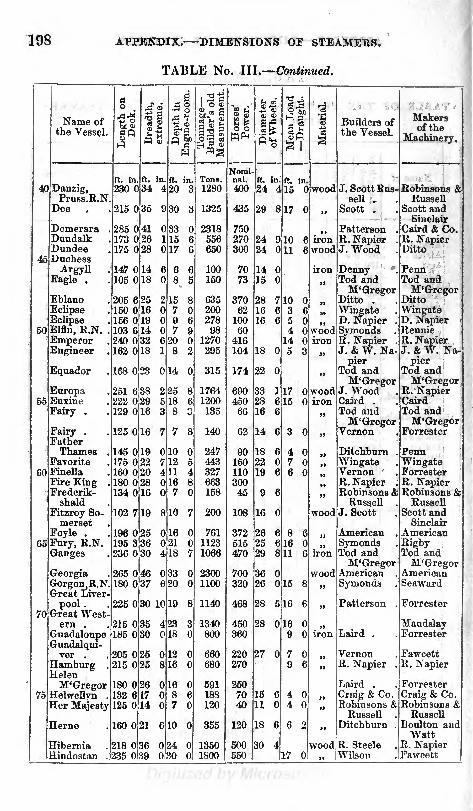
198 APPENDIX. DIMENSIONS OF STEAMERS.
TABLE No. III. Continued.

APPENDIX. DIMENSIONS OF STEAMERS. 199
TABLE No. III. Continued.

200 APPENDIX. DIMENSIONS OF STEAMERS.
TABLE No. III. Continued.

APPENDIX. DIMENSIONS OF STEAMERS. 201
TABLE No. III. Continued.

202 APPENDIX.
TABLE No. IV.
TABLE OF THE PRINCIPAL DIMENSIONS OP TWENTY-EIGHTMERCHANT STEAMERS WITH SCREW PROPELLERS.

APPENDIX.
TABLE No. V.
PADDLE WHEEL STEAMERS IK HER MAJESTY'S NAVY A \ i)
POST OFFICE SERVICE.
203

204 APPENDIX. HER MAJESTY'S NAVY AND POST OFFICE SERVICE.
TABLE No. V.Cbntinufd.

APPENDIX. 205
TABLE No. VI
TABLE OF EXPERIMENTS WITH H. M. SCREW STEAM-
TENDOER, "DWARF."
Burthen in tons, 163 1|. Nominal horse power, 90. Draught of water, 7 feet
aft ; 5 feet 10 inches forward. Fitted with a common two-threaded screw, 5 feet
1 inch in diameter, with common pitch.
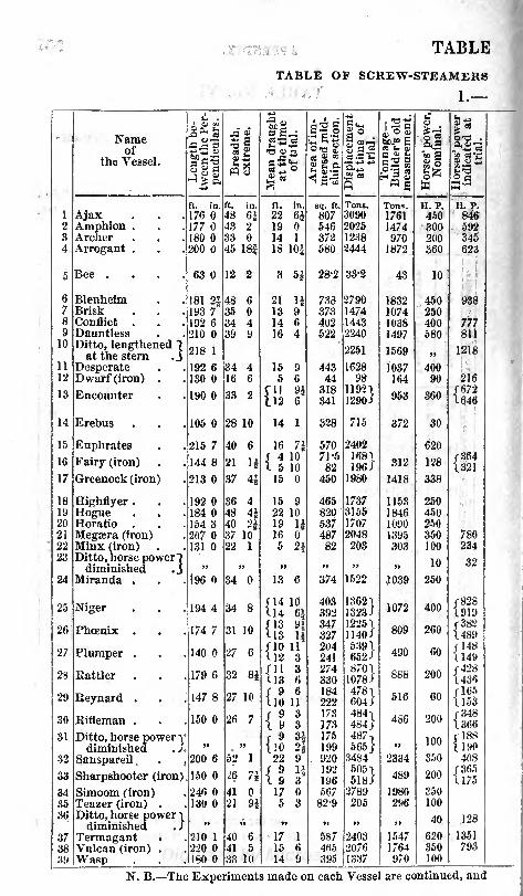
TABLE
TABLE OF SCREW-STEAMERSi

No. VII.
IN HER MAJESTY'S NAVY.
Vessel.

208 APPENDIX.
TABLE No.
TABLE OF SCREW STEAMERS
2. Propeller, and
Name of the Vessel.

APPENDIX. 209
VII. Continued.
IN HER MAJESTY'S NAVY.
Proportional Numbers.
Rate ofScrew.

TABLE No. VII. Continued.
TABLE OF SCREW STEAMERS IN HER MAJESTY'S NAVY.
3. Engines.

r -- _
.= ~
^ -T ^!
" _ r
_- -*
= ^ j:
-:
-
= - EB 3 aS -5 =
- -1.
i. ~!- ^=
HI
~ '
= : -c -~ .-- -
1*1S i =
7 :
I!i = ~=
. -
Weight of total Ma-chinery, pt-r Admiralty

Number of fires.


aa
I
H fa
S
H aH ^02 s^
e
O -fe ~-
o
31V(5

e

cc f
i" d
.2S3S o-o
si!-+ c. n ^ o Ci to i i i^-wcccc cc-^ff. m cu^ c
''
ns<4i
1
oEH
>
SWKa
KJftft
<1ft
&<O
OO-?
w>w=frl
-fa
oBn̂<fr
o- s t- ao 05 oo i
oo iK roo rH ^H
ooekirtc;cot>*^HmGCC'*CDC.os (^ -f -H 5-. eg -t- ^-i c< ?o c? S" Nab O5 OJo -H
JNg
-2 33 o-o
&
.
. -
c; ^ cc c x o r *i-^ ^r 3s :b * ** '- > ci ^ ^ ?-? o t>-
t1* oc CiO O r-^>~ ?* cc -^ o o :S i^-x x c; C O ^ c-/ cc tc -t< i* 2 co
Ci Ci o > ' ' | ocotc-*t<mio^t^ccicc-co^^c^cJcc <^'^| irtcoi -f. 3 M c (^ -f "JC I-T c> c; tc co o t^ i"5 oi o c; r: o f^ 10 35
o> o >^ 85 w^^ 10w ^ 35 rt JH SojS in 53 50 85
^ a'S <o o 5o aoSo o 2n f Cfc.CQ^'MCCt'tl ^o
'^ccomei eo ao IN IT- r-< ift o **" Gi CO t^ WTS r-n i^ ji if x to r- rn toomc 2 j-: . is & x >-T x - i^ cco -c sc r;- cs c-J x is * -r < (^ -5 ow c~. c c i i N IN sc ^< TH in s co t^- x 5o cv w. o ii ^ ft cc ec -t< o ic co (S
o -^ (? oo5 t< <-u5 t-t ao csovO" i ic w (<(Hii5c.c5cso^^^H^r-4 r-l -H * -H -^ ^H , 1 ^H f- -J? If! ifj !^J ^5 CI O> O' ^^ ~' ~l '' ~> ? 55
c I SGr ^ti
t^ps o* yj go > i * to Os o?m qo r-ms to Q> e*a t^w co <o e* * t^ow co ^-< i^-f = ISM si i!} oo-t<o r^cj c;. i.o >MX < i^c^ c-. ? x o !?-ooo ac S 5 FMe4S5Ttnr5inciscot^cca6d-. ec-5-<?>* in tnciSs
'^-*C^COmOrH^fl>ffiK^O^xKrHFCft*>^ *o in o o i x x: c; o o ^ ^' C 1 ' c^ ^5 1* ic n 5
^ -
J2 41 3S o-^
. >- c2 0/g
~ag
-^ 't -^ co co cc TJ c; c-i -H r-t co o c o f. o-. c~. a rf> ao oo (- i^- r- to' ' '
-H''Mc-t- OL;o
: S-. dc '?5?'r:r7-i-r,": ;
Revolu ions
pe
min.

APPENDIX. 217
if-i = 222S:S::
-- S! vr x -
t i r
~ ~ ~' ~ -'
_ e --: 5 : ?; S H; -, re f ?: S 5 f Ri s.'= aSRSSS2S2l&isl5|i
=2= :iS5?S2 "'-
_ i-: -- ~: ?t-
- " =s - =
=| -^^^Si- z,:2 ^^^S2^^;??;^rr:SIS&?5S7 -S5
t- X - - rt - t- X - ' ~
i";~ X"^('- '""- -X^'^C^ *-"^* rt 3C ?*
r ;^'^ ~-~TrtrCT'^^~. C^Xf'* f^- ^C ^C
5t"~^ t'"^IZi-Z-iZI!^^zzi -T _ LI
*^5 *'
S5.5 4? i i f x si irrrg^
^ ?iS^^S ^S =" 35 S*^ J fe SJ
~
a -
~. i~ O rr = X ~ ^r ?< ~. l> i-^ re = X~. x x x x x x r- c- 1^- c t- 1; --r -: ?i 3 LI t
MJ~- '
.
& = E -d f
. ~= -
psflj
.2 ^ C - f
3353=- ===*> *> C"o
ll-'~ =.= *
Ci"" O
3?= -- ,-E
5 = = =
t^\^ ^ ~
" ;2i t^
.= 4j< o i c^ x :
?: i' :-? ^ - - z: *. - 5 ?' - x x - - - - -
TT LS C-- X ~. C%~ C' H ^r ^ '2 i^ X ~
Ji
t^ x r-. o ? T T o -^ r^ x c: =
(^ :? r? i' x 3: r? 5 x S ?; H S;* S
13 --c t^ x 2 r. s r) ~- ^. - u- v; r- N x ?.
s -t:c-4'ia s i* oo Si s -'^ ^ f^ rH r^ " F^ i-^ ^^ ?* C<
z == 2"Z E-^ -~
a * <j^?.= D ss a

218 TABLE No. XII.
1. SHOWING THE ECONOMIC VALUES OF DIFFERENT COALS.

TABLE No. XII. continued.

APPENDIX.
TABLE No. XII. continued.
2. SHOWING THE COMPOSITION OP AVERAGESAMPLES OF THE COALS.
Localityor
Name of Coal.

APPENDIX. 221
TABLE No. XII. continued.
Localityor
Name of Coal.

222 APPENDIX.
TABLE No. XIII.
TABLE OF THE TEMPERATURES AND RELATIVE VOLUMES
OF STEAM OF DIFFERENT DENSITIES.
Pressurein poundsper square
inch.

APPENDIX.
TABLE No. XIV
223

APPENDIX.
TABLE No. XIV. continued.
o
fO
t^- CO i I in i 1 l JO O
i ioi *t>.coo
OOl ttl (
i iJOJOQOGO
w
iMi i <r-icoi "coc(Mt>.i i
in to i i in ^i (
<Mr-r-tCOint^
OJOOOOCi(MOJOC>t>.r-ii i
'-^irt<Meo
p imocoeoo
i iinooeoo
ocoi>.inao- i

APPENDIX. 225
REPORT TO THE DIRECTORS OF THE GRAND CANALCOMPANY, ON SCREW STEAM BOATS.
GENTLEMEN, I regret exceedingly that from various causes, over which
I had no control, I have been prevented until now from reporting on the
two steam boats in use on your canal, although the experiments made
with them have been completed some time ; but I hope my preliminary exa-
mination and report on these two boats has prevented the inconvenience
that would otherwise have arisen from this delay, as it has enabled you to
order a boat which, I have no doubt, will be found more suited to the traffic
on your canal than either of those now employed upon it. I do not, how-
ever, claim any merit for the plans or arrangement of the machinery in-
tended for this boat, all of which were prepared by your own officers, and
whatever merit it may have is entirely due to them ; all that I could do was
to satisfy myself from the experiments and examination of the two boats,
which was the best constructed, and, under similar circumstances, produced
the best effects, and to recommend to you that form of construction for the
boat you were about to build, which from these experiments I was enabled to
do with perfect confidence ; at the same time I do not by any means pretend
to say that a better form of boat, and more efficient machinery, may not be
hereafter constructed, when more experience and practical knowledge shall
be obtained by the working of these boats ; for, when locomotive engines
were first introduced upon railways, they were very much inferior to those
now used. Almost every one which has been since made up to the present
time has been an improvement on those previously constructed, either in
strength, efficiency, or economy of working ;and I have no doubt but similar,
or at all events very great and important improvements will be made in
steam boats for canal purposes, when they become to be more generally used
and more attention shall be paid to them by practical men.
In ordeer, howevr, to enable me to report on the queries put to me by
your Secretary, I thought it necessary to make a careful examination of the
two boats at present at work on your canal, and also to ascertain by experi-
ment the power and capabilities of each of these boats under different cir-
cumstances, as well in reference to the load they could carry as to the load
they could haul with different velocities. In making this examination and
experiment I was assisted by your excellent Secretary and intelligent Super-
intendent of Works, Mr. Talbot, who gave me every information, and aided
me in every way in their power.
L3

226 APPENDIX.
The first of these boats which I examined, called No. 2 Boat, was con-
structed by Messrs. Robinsons and Russell, of London. It is built of iron,
without ribs, is 60 feet long, and 12 feet beam, and is propelled by one screw,
driven by an engine of the following dimensions : boiler 2 feet 6 inches
diameter, containing 74 tubes of If inches diameter each j the length of the
tubes is 4 feet 6 inches, with 2 oscillating cylinders of 5 inches diameter,
and 15f inches length of stroke. Pressure 50 Ifos, and calculated to mate 120
strokes per minute ; the thickness of boiler f, with 5 stays of round |-inch
iron to strengthen the steam chambers.
The diameter of the screw is 4 feet, width of blade 1-11/ pitch of screw
6 feet, stern post 5f inches below keel level.
No 1 Boat was built at the Ringsend Works, and the engines and ma-
chinery were made and put into her by Mr. Inshaw, of Birmingham, who
has constructed several steam boats used on English Canals. The length of
this boat is 60 feet, and its width 12 feet. The boiler is 4 feet 6 inches in
diameter, containing 48 tubes of 2 inches diameter, and 6 feet long; the
cylinders are 7 inches in diameter; length of stroke 18 inches, and calculated
to make 120 strokes per minute, the pressure being 50 Ibs. The boat is
propelled by two screws, 4 feet pitch, 3 feet in diameter, and 2 feet long,
placed at each side of the stern post, worked with bevelled gear and two-fold
multiplying power.* This principle of construction appears to answer very
much better than that of No. 2 Boat, with one screw, for it is capable of
being stopped and the motion reversed with much greater ease than the
other, and it steers stern foremost almost as well as when running forward,
which is a most important and essential requisite in any steam boat employedin Canal traffic, where obstacles and interruptions are so frequent, and which
might be attended with danger, if the power of reversing was not easy and
effective : in this respect it is very superior to the boat with one screw, which
does not steer at all when the motion is reversed, but runs direct across the
Canal to one side or other, according to the position of the boat at the
moment of reversing. This boat (No. 2) was engaged by the builders to
* These screws are what is usually termed right and left handed ; they
consequently work in opposite directions. This is an improvement first
adopted by Mr. Inshaw, and is found to be most important as to the workingeffect. Any person who has attentively watched the effect of a single screw,will have observed that the current of water thrown back from it does not
take a direction in a right line with the boat, but in one at a diagonal with
that line. By Mr. Inshaw's arrangement of the two screws, the two diagonallines being in the direction of the streams from the two screws, are thrown
inwards, meeting immediately behind the rudder. The resultant is neces-
sarily a straight line of current in the centre of the canal, manifestly advan-
tageous as regards the action of the screws, and strikingly so as regards the
facility with which the boat is steered, and the power of the rudder.

APPENDIX. 227
carry 40 tons gross, to be furnished with engines of 12 -horse power, (nominal,)
consisting of two oscillating cylinders, and a tubular boiler, with feed pipes
and reversing gear, and capable of going with that load at about 5 to 6 miles
per hour, and of propelling itself and another boat at the rate of about 3 Irish
miles, or 3| English miles, per hour. This agreement does not however
s'ate what load the boat to be propelled or towed was to carry, but it would
appear to be the same as in the steam boat, that is 40 tons gross. By the
experiments made with this boat, it is evident that she falls very much short
of this performance, for, with 41 tons, she went only at the rate of 3^ miles
per hour, instead of 5 to 6 miles ; and when towing a boat loaded with 52
tons, she went at a rate of only 2^ miles per hour, instead of 3f . In fact,
when loaded with 20 tons only, she went at the rate of 4 miles only per
hour ; this discrepancy would appear to arise from want of power in the
engines, for it does not appear that they are more thanS-horse power, instead
of 12 ;it may, however, be possible, that other circumstances connected with
the form or arrangement of the screw may be the cause of the want of speed,
but want of power in the engine is the most apparent defect; before, how-
ever, drawing any conclusion from the experiments referred to, it will be
proper to describe them. The first set of the experiments was made on the
24th of April ; the weather was cold, but there was little or no wind to affect
the free movement of the boats.
First Experiment, 24th April, 1851, was made with Steam Boat No. 2,
loaded with 41 tons. The distance of half- a-mile (measured) was run in
8' 25", being at the rate of 3'56 miles per hour. During this experiment
the pressure on the boiler was 501bs. and the average number of strokes
was 102.
Second Experiment. In this experiment the boat was loaded with 41 tons
as before, and a barge was attached to it by a tow-rope. This barge was
loaded with 52 tons : the pressure was 42tbs., and the average number of
strokes per minute was 87. The same distance as before was run in 13' 6",
or at the rate of 2 '29 miles per hour.
Third Experiment. In this experiment two barges were attached to the
steam boat ; one was loaded with 53 tons, the other with 30 tons, besides
the 41 tons in the steam boat, in all 124 tons. The pressure on the boiler
was 501bs. as in the first experiment, and the average number of strokes of
the piston was 98, whilst the time occupied in passing over the same space
was 14" 40', or at the rate of 2'05 miles per hour.
On the 26th April the following experiments were made with the same
boat.

228 APPENDIX.
First Experiment. The boat was loaded with 20 tons, the pressure was
50lbs. on the safety valve, the average number of strokes was 100 per
minute, and the same distance of half-a-mile was run in 7' 30", or at the
rate of 4'0 miles per hour.
Second Experiment. In this experiment one barge, loaded with 50 tons,
was attached to the steam boat loaded with 20 tons ; the pressure as before
was 50 fbs., and the average number of strokes per minute was 90, whilst
the same space ran over required 12' 20", or at the rate of 2*43 miles per
hour.
Third Experiment. In this experiment two boats loaded with 50 tons
each were attached to the steam boat loaded with 20 tons, in all 120 tons
of goods ;the pressure was 50 fbs., the average number of strokes was 94, and
the space was passed over in 12' 55", which was at the rate of 2*31 miles per
hour.
On the 5th of May the following experiments were made with No. 1 steam
boat, having two screw propellers.
First Experiment.-~-The boat was loaded with 20 tons of goods ; the same
half-mile distance was run over as in the former experiments with No. 2 boat ;
the pressure was 45 Ibs., the number of strokes averaged 110 per minute;
the distance was run in 6' 41", which was at the rate of 4*49 miles per hour.
Second Experiment. In this experiment a barge carrying 50 tons was
attached to the steam boat, which was loaded with 20 tons ;the pressure
was 49 flos. as before ; the average number of strokes per minute was 101,
nd the time was 9' 12", which was at the rate of 3'26 miles per hour.
Third Experiment. In this experiment three boats were attached to the
steam boat one was loaded with 50, the second with 27 tons, and the third
with 34 tons, in all 131 tons, including the 20 tons in the steam boat; the
pressure was 49 Ibs., the average number of strokes per minute was 96,
and the time occupied was 10' 58", which was at the rate of 2*73 miles per
hour.
One fact, but certainly a most important one, has been established bythese experiments, and that is, that a very much greater and useful effect is
produced by hauling than by carrying. This fact was exemplified in every
experiment that was made, though it was more apparent in one of the boats
than the other, as will be seen by reference to the experiments; it also
appears that one form of boat and machinery is less affected in speed than
the other by a proportional increase of weight hauled than carried ; from this,
it is evident that the form of boat and machinery most suitable for carrying

APPEKDIX. 229
goods will differ from the form of boat and machinery suitable for haulage.
The barges and boats on your Canal are much too large, heavy and unwieldly ;
they are a heavy load in themselves, and require considerable power to move
them, even at a slow rate, when empty ; they are also formed as if they were
to be employed as sailing barges, similar to those on the Thames and other
rivers : this is a very great mistake and quite unsuited to Canal navigation.
If the boats were built 60 feet long, 6 feet 6 inches wide, with upright sides,
and upright cornered bows, which would admit two of them to enter a lock
at the same time, a great amount of saving would be effected on your Canal
in the power required to haul such boats, as compared with those now in use,
for I have no doubt that six of those boats carrying 35 tons each, would be
as easily hauled as two of the present boats 50 tons each or in the ratio of
210 to 100 and that such a steam boat as No. 1, at present in use, would
be enabled to haul these six boats carrying 210 tons of goods at the rate of
three miles an hour, and carrying at the same time 20 tons of goods, besides
the 210 tons hauled. I would, therefore, strongly recommend you to have
two such boats built, and if you found that the saving in power required for
hauling was what I have stated, it would be judicious to have all new boats
built on the same plan. I am well aware that it is very difficult to get parties
long accustomed to a particular form of boat or carriage to adopt a different
one ;but I am convinced the advantages of the light and narrow boat would
be so apparent that it would in a short time be universally used in Canals in
this country, as such boats are at present used in most of the Canals in
England and Scotland ; and in any future engines that may be ordered for
your Canal, I would recommend that the fire-box should be made as large
as the construction of the boat will admit of, and that the draught up the
flue be as moderate as possible, as more suitable to a turf fire than one of
coke, for there cannot be a doubt, but turf or peat fuel will answer every
purpose of working steam boats on the Canal, and will be very much cheaperthan either coal or coke. My replies to the queries put to me will form the
subject of a further report, which shall be submitted with as little delay as in
my power.
JOHN MACNEILL.


GLOSSARY
OF
TEEMS CONNECTED WITH MAEINE ENGINES
AND BOILEKS.
(WITH FRENCH TRANSLATIONS.)
Air-casing, of thin sheet iron, (la
chemise,) surrounds the bottom of
the chimney to prevent the radia-
tion of heat to the deck.
Air-pipe, a small copper pipe lead-
ing from the top of the hot-well
through the ship's side, for the
discharge of the air and uncon-densed vapour pumped by the air-
pump.[ir-pump, (la pompe a Fair,) is re-
quired to maintain the vacuum in
the condenser by withdrawing the
condensing water, air, and uncon-densed vapour.
[ir- tubes, are small wrought-irontubes hung in the coal-boxes fromthe deck and filled with water, for
the purpose of ascertaining the
temperature of the coals by a
thermometer, as a precautionagainst spontaneous combustion.
Angle-iron, (corniere).
Annular-piston, is one made in theform of a ring encircling an inner
cylinder which is enclosed withinthe external one. This arrange-ment is sometimes adopted to gainlength of connecting-rod, by caus-
ing it to descend within the inner
cylinder.Anvil, (masse).Ash-pits, (cendriers,) underneath the
fire-bars of the furnaces, where theashes collect.
Atmospheric or singk-acting engine,
(machine a vapeur atmospherique,)is a condensing engine in which the
pressure of the steam acts duringthe up-stroke only, the returnstroke being performed by the
pressure of the atmosphere actingagainst a vacuum.
Auxiliary orfeeding engine, (machinealimentaire,) fitted to supplytubularboilers with feed-water when the
large engines are not working, andthe ordinary feed-pumps are there-fore inactive.
Axle, (tourillon).
Babbifs patent bushes, are formed ofan alloy of 1 Ib. copper, 50 Ibs. tin,5 Ibs. regulus of antimony.
Back-balance of eccentric, is fixed tothe back of the eccentric pulley for
the purpose of balancing its weighton the shaft.
Back-balance of slide valves, is the
weight fixed at the extremity ofthe valve-lever for balancing the
weight of the slides.
Back-lash, is the term given to the
jar which ensues when one portionof the machinery which receivesmotion from another (but without
being always in actual contact) hasits velocity so increased from someextraneous cause, that it falls back,with a sudden blow, upon the partfrom which it ought to derive its
motion.

232
Back-links, the links in a parallelmotion which connect the air-pumprod to the beam.
Ballast, (sable).
Banking-up the fires, raking them to
the bridge of the furnace, and then
emothering them with cinders andsmall coal, the draft being at thesame time checked. By this meansthe fires are kept in a state of
languid combustion, but are readyto burn up briskly again whensteam is wanted at short notice,the red-hot mass being then broken
up, raked forward, and the draft
re-admitted.Barometer or vacuum-gauge, (baro-
metre,) is fitted to the condenserof an engine to show the vacuum.It resembles the common weather-
barometerj except that the top of
the tube is in communication withthe condenser.
Barrelofa pump, (corps d'une pompe).Base-plate, see Sole-plate.Beam or side-lever engines, (machinesa balanciers,) are those in which themotion of the piston is communicat-ed to the crank through rockingbeams or levers at the sides.
Beams of a vessel, (travers).
Bearers, are the cross bars in thefurnaces supporting the ends of thefire-bars.
Bear, is a small apparatus for punch-ing holes by hand.
earing, neck, or journal, of a shaft,
(coussinet d'une arbre,) is the partwhich revolves within the pedestal-
brasses, and supports the weight or
strain.
Bedding of a boiler, is the seat onwhich it rests.
Bilge-pumps, worked by the engine,to clear the water from the bilgeof the ship.
Blowing-off, the process of ejectingthe super-salted water from theboiler in order to prevent the de-
position of scale or salt.
Blow-off cocks and pipes, are those
through which the brine is eject-ed.
Blowing-through, (purger d'air,) is the
process of clearing the engine of
air by blowing steam through the
cylinder, valves, and condenser,before starting.
Blow-through valve, (soupape a purger
d'air,) is fitted between the valve-
casing and the condenser for thetemporary passage of the steam usedin blowing through.
Boiler, low pressure, high pressure,(chaudiere a basse pression, a hautepression) .
Bolt, bolted, (boulon, boulonne").Boss, ( renflement, ) is a centre or
swelling of any kind in which ahole or eye is bored.
Box-keys, are the upright keys usedfor turning the nuts of large bolts,or where the common spannercannot be applied.
Bracket pedestal or plummer-block , is
the fixed support for the bearingof a shaft in motion, formed so thatit can be fixed vertically to theframe of an engine, or the side of a
beam, &c.
Brass, (bronze,) an alloy of copper,tin, and zinc, in different propor-tions. Tough brass, for engine-work, is formed of 10 Ibs. copper,1 Ib. tin, and 1 Ib. zinc. Brass,for heavy bearings, of 1 Ib. copper,2^ oz. tin, ^ oz. zinc.
Break or brake, (frein).
Bridge of a boiler, is the barrier of
fire-bricks, or iron plates contain-
ing water, thrown across the fur-nace at the extreme end of the
fire-bars, to prevent the fuel beingcarried into the flues, and to
quicken the draft by contractingthe area.
Brine-pumps, (pompes de saumure,)are worked by the engines to with-draw the super-salted water fromthe boilers methodically, insteadof by periodical blowing-off.
Bulkheads, (cloisons).
Bush, is a lining of brass, steel, orother metal, fitted in an eye or
bearing, either to diminish friction
or prevent rapid wear.
Callipers, are compasses with roundlegs, used for taking the diameter orthickness of circular or flat inside
work about an engine. Inside
callipers are used for measuring theinternal diameter of a brass or holeof any kind.
Cam, for expansion, is a disc of cast
iron, having the periphery cut in
an irregular figure, for giving the
proper motion, to the expansion

MARINE ENGINES AND BOILEBS. 233
valve. It is graduated in steps so
as to suit the different degrees of
expansion.Carriage by sea, (transportation) ;
by land, (montage).Cast, (coule).
Cast-iron, (fonte).
Cataract, is a contrivance introduced
into marine engines for softeningthe fall of the expansion valves
when these are made upon the Cor-nish principle. It consists of a little
brass cylinder filled with water or
oil, and fitted with a solid pistonconnected by a crosshead with thevalve spindle. The fall of the valveis checked and regulated by the
escape of the water or oil througha small hole bored for that purposein the side of the cylinder, the pis-ton of the cataract descending ac-
cording as the liquid is forced outfrom before it by the pressure dueto the weight ofthe expansion-valve.
Cement, (ciment, mastice).
Centre-boss, of the paddle-wheels,(renflement central dea roues a
aubes) .
Chimney, (chemine'e).
Chisel, (ciseau, burin).
Clack-valve, a flat valve with a hinge-joint.
Clearance of the piston, is the small
space left between the piston andthe top and bottom of cylinder atthe end of each stroke.
Clinkers, (scories,) are the incom-bustible matter left on the fire-bars
during the combustion of the coal.
Clinker-bar, is fixed across the top ofthe ash-pit to support the slice usedfor clearing the interstices of thebars.
Clothing the steam-pipes, boilers, &c.,means covering them with felt andother non-conducting materials, to
prevent the radiation of heat.
Coals; coal bunkers, (les houilles,charbon de terre ; soutes a char-
bon).
Coal-trimmer, a man whose duty it is
to work within the coal*boxes, andbring the coals to the doors at theboiler front as they continue to beconsumed.
Cock, (robinet).Cogged wheels, (roues dente"es,) arethose fitted with wooden teeth or
coys, for the purpose of lessening
friction and giving smoothness ofaction.
Cold- chisel, a chisel properly temperedfor cutting cold iron.
Collar of a shaft, (collier,) is the pro-jecting rim on each side of the neckor bearing, to confine it sidewaysduring its revolution.
Common steam, (in contradistinction
to super-heated steam,) is steam in
contact with the water from whichit was generated.
Condenser, (condenseur,) is the cast-
iron box in which the process ofcondensation takes place.
Condensing engirt, (machine a con-
densation,) is one in which thesteam is condensed after leavingthe cylinder, for the purpose of
gaining the effect of the atmosphe-ric pressure.
Connecting-rod, (bielle de la mani-
velle,) in a direct-acting engine,communicates the motion directlyfrom the head of the piston-rod tothe crank : in a side-lever engine,from the cross-tail to the crank.
Consumption of fuel, (consumationde combustible),
Counter, a little instrument employedfor registering the strokes of a,u
engine,
Coupling of a shaft, is the mode of
connecting together two or morelengths of a revolving shaft, by-
shaping the ends into flat surfaces.
or bearings, which are held togetherby a strong iron collar or coupling*box.
Cover or lap of the slide-valve on the
steam side, is the space which it
advances beyond the opening of the
steam-port after it has closed it,
and . is given for the purpose o(
causing the engine to work expan-sively, by cutting off the admission,of steam before the end of thestroke.
Cover or lap on the exhausting side ofthe piston, causes the passage to thecondenser to be closed before the
end of the stroke, the piston beingthen said to be cushioned by the
elasticity of the confined vapour,upon which it descends.
Crank / cranked, (manivelle, coude ;
coud6).Crew of a vessel, (requipage d'wa
vaisseau).

234 GLOSSARY or TEEMS CONNECTED WITH
Cross-head, (traverse, tete croissee,)in a side-lever engine, crosses thehead of the piston-rod, and com-municates the motion to the side-
rods.
Cross-tail, in a side-lever engine, takesthe motion from the side-rods andcommunicates it to the connecting-rod.
Cup-valve, resembles a conical valve,but has no spindle, being turned in
the form of a cup or portion of a
sphere.Cushioning the piston, means that asmall portion of steam is shut upbetween the piston and the cylindertop and bottom at the end of each
stroke, which acts as a spring to
soften the shock, and to give the
piston a start forward after thecentre is turned. This effect is
produced by the lap of the side-
valve on the exhausting side.
Cutter, (clavette,) is the wedge-keyused, in combination with the gib,
(contre-clavette,) for tightening the
strap and brasses of a bearing, asthe latter wear by friction.
Cutting- off the steam for expansion,(la detente).
Cylinder-cover, (couvercle de cylin-
dre).
Dampers, (les registres,) are iron
plates, fitted by a hinge or otherwise,across the fronts of the ash-pits andthe bottom of the chimney, for the
purpose of regulating the draft.
They are capable of being adjustedby hand to any desired area.
Dead-fires, when they burn sluggishly.
Dead-plate, a flat iron plate frequentlyfitted before the bars of a furnace,for the purpose of coking bitumi-nous coal upon before it is thrownback upon the fire.
Dead-water, (eaumort,) is the current
following in the wake of a ship and
partaking of her motion.Deck, (pont).
Depth of a vessel, {hauteur d*un
vaisseau) .
Diagram of indicator, the figuretraced by the pencil, from whichthe pressure is calculated.
Dip of the wheels, the depth of waterover the top of the vertical board.
Direct-acting engines, are those in
which the motion of a piston is
communicated directly from thehead of the piston-rod to the crankthrough the connecting-rod, with-out the intervention of side-levers.
Discharge, delivery, or waste-water
pipe and valve, (tuyeau et soupapede decharge, ou de sortie,) are those
through which the heated condens-
ing water and vapour are dischargedinto the sea by the air-pump.
Disengaging or disconnecting the pad-dles or screw from the engines, (bysuitable machinery,) permits themand their shaft to revolve freely in
the brasses by the reaction of the
water, by which means the speedof the ship when under canvas is
not so much affected as if they weredragged through the water.
Displacement of a vessel, is the weightof water which she displaces, beingof course equal to her own weight.
Donkey or auxiliary engine, (ma-chine alimentaire ) is used for feed-
ing the boilers while the large en-
gines are at rest.
Double-acting engine, (machine adouble action,) is one in which thesteam acts against a vacuum oneach side of the piston alternately,as in the ordinary marine engine.
Double-actingpump is one which lifts
and forces water alternately, bymeans of a solid piston or plungerand an entrance and exit valve
communicating with each side, (asthe feed and bilge pumps of a ma-rine engine).
Double-cylinder engine, as patented byMessrs. Maudslay, has two cylin-
ders, between which the lower endof the connecting rod descends, its
motion being communicated fromthe piston-rod by a bent crosshead
working in grooves between the
cylinders.
Draught of the chimney (tirage).
Draught of water (immercion).Drift is a round piece of steel, made
slightly tapering, and used for en-
larging a hole in a metal plate bybeing driven through it.
Drip-pipe, is a small copper pipeleading from the waste steam pipeinside, to carry off the condensedsteam and other hot water which
may be blown into the "trap" at
the top.
Driving-wheel, (roue motrice,) in the

MAKIXE ENGINES AND BOILEHS. 235
gearing of a screw vessel, is that
which communicates motion to the
small wheel or pinion.Drum is a hollow cylinder fixed on a
shaft for driving another shaft bya band.
Dynamometer is an instrument for
indicating the thrust of the screw-
propeller by means of springs andlevers.
Eccentric, (rexcentrique,) is the ar-
rangement usually adopted for giv-
ing the proper stroke to the valves.
It consists of the eccentric pulleyof cast iron, which is loose on the
intermediate shaft, and the hoopof wrought iron lined with brass,which encircles the pulley, and
gives motion to the eccentric rod.
The eccentric stops or nugs are twolittle projections fixed on the inter-
mediate shaft for the purpose of
carrying round the eccentric pulley,
according as it is wanted to goahead or astern, the pulley itself
being free to revolve backwards or
forwards between the two stops.The weight of the pulley is balancedon the shaft by the back-balancecast on it.
Eduction or exhaust passages (tuyeauxde sortie, ou d'emission), throughwhich the steam passes from thevalves to the condenser.
Effective diameter of a paddle wheelis generally reckoned at one third
of the breadth of the boards fromeach extremity of the diameter.
Effective heating surface in a boiler is
that which is considered of value in
evaporating the water. The bottomsurface of the flues and furnaces,and one third of the whole surface
of the tubes in tubular boilers, are
usually rejected as ineffective.
Engine beams cross through the en-
gine room at the height of the en-
tablatures, to steady them, and re-
ceive part of the thrust of the
paddle wheels.
Engine bearers or sleepers, (poutresde fondement,) are the longitudinalkeelsons through which the foun-dation plate is bolted.
Engineer, engine tenter, (machiniste,mechanicien).
Entablature is the strong iron frame
supporting the paddle shaft. It
usually receives additional stiffness
from being confined between twobeams of timber, called the entabla-
ture or engine beams.
Equilibrium, Cornish, or double-beat
valies, are frequently used in marine
engines as expansion valves. Their
peculiarity consists in tlieir beingpressed by the steam equally in all
directions, so that they rise with a
very slight force, exposing at thesame time a large area of steamwith a very small rise of the valve.
Escape or priming mlves, (soupapesd'echappement,) are loaded valvesfitted to the top and bottom of the
cylinder, for the escape of the con-densed steam, or of water carried
mechanically from the boilers withthe steam.
Escape-valves are also fitted to thefeed pipes as a means of exit for
the surplus water not used by theboilers.
Expansion gear, (1'encliquetage pourFexpansion,) is fitted to marine
engines, independently of the cy-linder valves, for the purpose of
cutting off the steam at different
portions of the stroke, according asit is wished to economize fuel moreor less. It generally consists of agraduated cam on the paddle shaft,
against which a roller presses andcommunicates the movement pecu-liar to the irregular surface of the
cam, through a series of rods andlevers to the expansion valve, situ-
ated between the throttle valve andthe slides.
Expansion or Fa u-cettjoint is a stuffing-box joint used when a straight metal
pipe, (as the steam pipe,) which is
exposed to considerable variations
of temperature, has no elbow orcurve in its length to enable it to
expand without injury. In such acase the pipe is divided into two
lengths, which are united by a
steam-tight joint accurately boredand turned, so as to allow the one
pipe to slip within the other, whenthey lengthen by expansion.
Eiperiment, (experience).
Eye of a crank, &c., (encoche, ceil,)
is a hole bored to receive a shaft or
pin.
Fawcett joint, see Expansionjoint.

236 GLOSSAET OF TEEMS CONNECTED WITH
Feathering paddle loheels (as Morganspatent), are those in which the
requisite machinery for featheringthe boards, or causing them to enter
and leave the water in a perpendi-cular position. By this means, the
board leaves the water without
lifting it, and the effect of the wheelis somewhat increased.
Feeding apparatus, (1'appareil alimen-
taire,) for a marine boiler, consists
of the feed pump, feed pipe, passingthrough the refrigerator, feed cock
on the boiler, escape valve for the
surplus water, and water gauges to
show the level in the boiler.
Feeding engine, see Auxiliary engine.Ferules (viroles) are rings of iron or
brass frequently used for fasteningthe tubes of a tubular boiler in the
tube plate.
Files, (limes).Fire bars, (barres du foyer).Fire grate, (grille du foyer).
Fire-hose, are made adjustible to the
discharge pipes from the bilge-
pumps, from the auxiliary enginewhere fitted, and from the hand-
pump in engine room.Fiie men or stokers, (chauffeurs,) the
men who work the fires,
Firlng-up, urging the fires to makethem form as much steam ag
possible.
Flange, (rebord).Float boards or paddle boards, (Les
aubes).
Flues, (conduits).
Foot-valve, ( clapet de fond,) is situated
between the bottom of the con-
denser and the air pump, openingtowards the latter.
Forcing pump?, (pompes foulantes).
Fork, (fourche).Fork head, the double head of a rod
which divides in order to form a
connection by means of a pin.
Foundation or base plate, (plaque du
fond,) see sole-plate.Fox key, is a key with a thin wedge of
steel driven into the end to preventits working back.
Frame of the engine, (chassis, cadre).
Frames of a vessel, (membrures d'un
vaisseau).
Friction, (frottement).Fuel, (combustible).
Fulcrum, (support, palier, crapau-
dine).
Furnace, (le foyer) .
Fusible Plugs, (bondelles fusibles,)are sometimes fitted in boilers,
being expected to melt by thehigh temperature of the confined
steam, and thus allow it to escapein case of its attaining a dangerouspressnre from the safety valve not
acting.
Gasket, (garniture d'6toupe,) is the
hemp packing, formed of soft cord
plaited, which is used for makingsteam-tight joints.
Gauge cocks, (robinets d'epreuve,) of
brass, attached to the front of theboiler for indicating the level of thewater.
Gauge, steam or mercurial, (mano-metre de verre mercurial,) is a
syphon tube half-filled with mer-cury, usually employed for showingthe pressure of low steam. Whena marine boiler uses steam of hightension, a spiral spring is employed.
Gib (contre-clavette), is the fixed
iron wedge used, in conjunctionwith the cutter or driving-wedge(clavette).for tightening the strapsand brasses of the different bear-
ings.
Gland, is the cupped collar (lined with
brass,) which encircles the pistonand air pump rod, &c., where it
passes through the cover, beingfor the purpose of holding oil or
tallow for lubricating, and for
compressing the packing of the
stuffing-box upon which it is
screwed down.Glass water gauges, attached to the
fronts of the boilers for showingthe level of the water.
Governor, (rgulateur,) in screw
engines, is an apparatus by whichthe steam is shut off from the
cylinders (when the speed of the
engine becomes too great), by the
divergence of two balls from the
centrifugal force, according as
their velocity is increased.
Grease cock on the cylinder cover, for
lubricating the piston with melted
tallow, without permitting the
escape of steam or the entrance of
air.
Groove, (trou, entaille).Guards for the bolts of an engine are
light frames of braas or iron, into

MABINE ENGINES AND BOILEES. 237
which the nuts of the bolts fit, to
prevent their working loose by un-
screwing.
Gudgeon, (goujon,) is any short pin or
ehaft used as a bearing for a movingportion of the machinery.
Guides, (glissoirs,) are smooth sur-
faces between which the head of
a piston rod, &c., slides to preserveits parallelism ;
the sliding block
attached to the cross head beingcalled the Guide block.
Gun metal, an alloy of brass very
generally employed in engine work.
It is formed by melting together1 Ib. of tin, 1 Ib. zinc, and 8 Ibs.
copper.
Hall's condensers, a method of sur-
face condensation in which the
steam is condensed by passing
through a large number of small
tubes immersed in cold water.
Hammers, (marteaux,) of three sizes,
the largest being called sledge
hammer; the next flogging hammer ;
and the smallest hand hammer.
Handle, (manette).Hand pump, (pompe a bras,) is fitted
in the engine room for filling and
feeding the boilers by hand, for
washing the decks, extinguishing
fire, &c. It is always made capableof being attached to the engineswhen they are working.
Heat, heating power, (chaleur, puis-sance calorifique).
Helm, helmsman, (timon, timonier) .
Hemp, (etoupe).
High-pressure, or more correctly non-
condensing engines, (machines a
haute pression,) are those whichwork simply by the excess of the
pressure of the steam above that of
the atmosphere. Condensing en
gines, although sometimes using"high-pressure" steam, are never
called high-pressure engines.
High-pressure steam, (vapeur a haute
pression,) is a vague expression de-
noting steam of a tension above 15or 20 Ibs. pressure above the atmo-
sphere.Holding-down bolts, are the strongscrew-bolts employed to fasten thefoundation plate of the engines to
the ship's bottom.Horse power, nominal, (puissance en
chevaux, force de cheval,) is as-
sumed equal to 33,000 Ibs. raisedone foot high in one minute.
Hot-well, (reservoir a eau chaude, la
citerne,) is the reservoir for thewater pumped out of the condenser
by the air pump.Hugging is the expression used whenone vessel is running so close inthe wake of another as to beinfluenced by the current of dead-water following her, in which casethe two may continue to keep close
together, although the vessel
running behind may be, perhaps,a mile an hour slower than theother.
Hull or shell of a boat, (coque d'unbateau).
Incrustation or scale, (sediment,) is
the hard coating of salt, lime, andother mineral substances whichcollect on the inner surface ofthe plates of a boiler which is not
regularly and sufficiently ''blownoff."
Index of a spring balance, (curseur).Indicator, (indicateur,) is the little
instrument employed for ascer-
taining the real power, as well asthe state of efficiency of the in-ternal parts, of a steam engine, byindicating the actual pressure inthe cylinder during each stroke,and the time and manner in whichthe steam is admitted and shut out
by the valves.
Injection, (injection,) is the processof admitting a jet of cold waterfrom the sea into the condenser, tocondense the steam as rapidly as
possible.Inside bearings of paddle shaft, (upona bracket bolted to the ship's side,)are employed when the wheels are"overhung."
Intermediate shaft is the strong shaft
crossing the centre line of thevessel and connecting the paddleshafts ofthe two engines.
Iron-filings, (limaille).
Joints, (charnieres, articulations).Journal, (coussinet,) is the neck or
bearing part of a shaft, uponwhich it turns and by which it is
supported.Junk ring, is a metallic ring confining
the hemp packing of the piston
(when such is employed), and made

238 GLOSSAET OF TEEMS CONNECTED WITH
capable of being screwed down to
compress it.
Keelsons, (carlingues).
Key, (clef,) a wedge piece of iron
used for tightening the brasses of a
bearing, &c.
Kingston's valves, are conical valves
with a screwed spindle, and are
very generally used for closing theorifices of the injection and blow-off pipes where they pass throughthe ship's side.
Knees of iron, ( 6querres en fer).
Lagging* for the cylinder, &c., are thethin staves of wood employed in"clothing," to stop the radiation of
heat and consequent condensationof steam.
Lap of the slide valve, see Cover.
Larboard engine, that on the left-
hand side of the vessel when look-
ing towards the bow.Latent heal, (chaleur latente, ) is that
portion of heat which is absorbed
by gases and liquids, in a latent or
insensible state, during their transi-
tion from a denser to a rarer form;
as when water at 212 changes into
steam at 212 3
,and when ice at 32
changes into water at 32.Lead <>/ the slide valve, (avance du
tiroir,)is the small space which the
valve opens to steam at the endof each stroke, upon the oppositeside of the piston. It tends to
check the velocity of the piston at
the end of the stroke, and allows of
the valve being open and ready to
admit a larger supply of steam the
instant the motion of the piston is
reversed.
Lead of the crank, (avance de la
manivelle). It is usual in direct-
acting, and generally in all un-
balanced engines, to give what is
called lead to one of the cranks;
which implies that the crank of the
one engine is set a little in advanceof the right angle to the other ;
namely, at 100 or 110 in place of
90. This assists in rendering- the
motion of the piston more uniform,
by moderating its velocity at the
end of the stroke.
Leather, (cuir).
Length of stroke, (longueur du coup,ou de la course).
Level, (niveau).Lever, (levier).
Lighter or barge, (gabarre).Links are short connecting pieces,with a bearing in each end, for
transmitting motion from one rodor lever to another.
Link motion, is an ingenious arrange-ment for working the slides, bywhich means the travel or stroke ofthe valve may be varied at plea-sure, and expansion given withouta separate expansion valve beingrequired. It also affords greatfacilities for stopping and reversingthe engines.
Log, engine-room, a tabulated sum-
mary of the performance of the
engines and boilers, and of the con-
sumption of coals, tallow, oil, andother engineers' stores.
Lubricators, (godets, ou boites a
huile,) are the larger description of
oil-cups for holding oil and dis-
tributing it to the working parts ofthe engines.
Main centre, (goujon central, ) in side-
lever engines, is the strong shaft
upon which the side levers vibrate.
Manhole, (trou d'homme,) is a holein a boiler or tank, fitted with a
steam-tight cover, through which aman may enter for the purpose of
cleaning and examining the interior.
Metallic packing, (for the piston,) is
composed of a ring or several ringsof iron or other m'etal, sometimescast so as to possess elasticity in
themselves, or sometimes cut into
segments and pressed against theinterior of the cylinder by springs,so as to form a steam-tight contact.
Metre, equals 39*3702 English inches.
Mile, Geographical or Nautical, or
knot, contains 6082'66 feet.
Mile, British Statute, contains 5280
feet, 1760 yards, or 1609 metres.
Mile-post, (borne milliaire).
Mitre-wheel, has its teeth set at an
angle of 45 with the spindle, so as
to transmit the motion to anothermitre-wheel and shaft at right
angles with it.
Morgan's feathering paddle wheel, see
Feathering paddle wheels.
Morticed, (assemble a mortaise).Mud hole, (orifice de nettoiement,)
fitted with steam and water-tight

MAKINE ENGINES AKD BOILERS. 239
doors, through which the deposit
may be removed from the boilers.
Muntz's metal, used for bearings, &c.,is formed of 2 parts of zinc, 3 parts
copper.
Rave of a wheel, (moyen).Keck ofa shaft, (con -sinet d'un arbre,)
is the jmirniil or bearing on whichit turns and is supported.
Non-condensing or high-pressure en-
gines, (machines a haute pression,)are those in which the principle of
condensation is not applied, themotive power being due solely to
the excess of the pressure of the
steam above that of the atmosphere.Notch, (encoche).Nut, (ecrou).
Oil-cups or lubricators, (boites a huile,)are fitted to the several bearings and
rubbing surfaces of the engine for
the purpose of lubricating them to
. diminish friction.
Oscillating engines, (machines aux
cylindres oscillantes,) are those in
which the cylinders oscillate uponhollow axes or trunnions, throughwhich the steam enters the valve
casing. By this arrangement, the
parallel motion and connecting-rodare dispensed with, the head of the
piston-rod being attached directlyto the crank-pin.
Outside bearings to paddle shaft, whenthe shaft runs through to a bearingon the spring beams.
Overhung puddle wheels, when theshaft does not run through to a
bearing on the spring beams, but is
supported by a bracket from the
ship's side.
Packing for the piston, slide-valves,&c.. (garniture,) is employed torender them steam-tight, and is
formed sometimes of rings of ironor other metal pressed outwards bysprings, (when it is called metallic
packing) ; sometimes by hemp con-fined by a "junk ring" and com-pressed by screws (called hemppacking) ;
and sometimes by ringsof vulcanized india rubber andother elastic material.
Pad'de wheels, paddle boxes, (roues a
aubes, tambours).Paddle boards or float boards, (les
aubes) ; paddle-arms, (les rais des
roues).Parallel motion, (le parallelogram,) is
the name given to the combinationof jointed rods usually employed in
side -lever engines (and others) for
preserving the parallelism of the
piston rod.
Pedestal or plummer block is the sup-port for a shaft in motion, holdingthe brasses on which it turns.
Pet cock or test cock is the name givento a little cock sometimes fitted at
the top and bottom of the cylinderto allow the escape of water fromabove and below the piston, inde-
pendently of the escape valves fitted
for that purpose. They are keptopen until the engines are fairlyunder weigh, and are then shut.
Pin, (happe, boulon).Pitch ofa screw is the distance between
the threads, or the distance whichthe screw advances during eachrevolution when working in a solid.
Pitch circles are the circles of contactof two or more toothed wheels
working in combination.
Pitching of a vessel, (plongement).Plates, (thin,) (lames, tolles).
Plug, (bouchon).Plummer block, see Pedestal.
Plunger, "(plongeur,) a solid pistonwithout valves used in the feed andbilge pumps, &c.
Ports of the cylinder are the shortsteam passages leading from the
top and bottom of the cylinder tothe slide-valve casing.
Priming or foaming of the boilers
implies that the water boils overinto the steam pipes which lead tothe engines, and is caused by thewater being dirty, or there being a
deficiency of steam-room in the
top of the boilers.
Priming valves, see Escape valves.
Radius of curvature, (rayon decourbe).Radius ro j
s or bars, (la bride du paral-
lelogram,) are the guiding rods in a
parallel motion jointed to the con-
necting links to counteract the
vibratory motion communicated bythe side levers.
Reciprocating, (alternatif).
Reefing the paddles, means disconnect-
ing the float-boards from the paddle-arms, and bolting them again nearerthe centre of the wheel, in order to

240 GLOSSARY OF TE11MS CONNECTED WITH
dimmish the dip when the vessel i
deep. This is sometimes done bymachinery in what are called
reefing paddle wheels.
Refrigerator, is a vessel containing anumber of copper tubes throughwhich the hot brine passes after
being ejected from the boiler bythe brine-pump. The feed wateris at the same time passed throughthe vessel surrounding the tubes,and has its temperature thus raised
by the waste heat of the brinebefore entering the boiler.
Reverse or vacuum valves, (soupapesde siiret6 interieures,) are smallloaded valves opening inwards, andfitted to the boiler to admit air
when a vacuum is formed by thecondensation of the steam inside,or when the pressure of the steamfalls to a few pounds below the
pressure of the atmosphere.Reversing gear is the apparatus pro-vided for reversing the motion ofthe engine by changing the time ofaction of the slide-valve. This is
done by bringing the eccentricbehind in place of in advance of thecrank.
Ribs, (tirans).
Rocking shaft, the shaft, with levers,
frequently used for working the
slide-valves, the notch of the eccen-tric rod dropping into a stud fixed
in one of the levers, and the links
of the slide-valve spindle beingattached to the opposite lever onthe same shaft.
Rubbing part, (partie frottante).
Rudder, (gouvernail).Rust joints, made by spreading overthe surfaces to be united a mixtureof one ounce ofsal-ammoniac to one
pound of cast-iron borings.
Safety valves, (soupapes de suret,) are
fitted to the boilers for the escape of
the steam, before it attains a dan-
gerous pressure.Salinometer , (salinom6tre,) is an in-
strument for measuring the quan-tity of salt contained in solution in
the water of the boiler, by indicat-
ing either the specific gravity, or
the temperature at which it boils.
Scale, (sediment,) is the hard crust of
salt, lime, &c., which collects uponthe interior surface of the plates of
a boiler when proper attention f
not paid to "blowing off." Thehammers used for loosening and re-
moving the scale are called scalinghammers.
Screw, screwed, (vis, viss6).Screw bolts, (boulons en vis, boulons
taraud6s).Seat of the valve, (sie'ge de la soupape).Sediment collectors or scale pans, areshallow vessels which are sometimesfixed in boilers about the level ofthe water, for collecting the parti-cles of sediment which are buoy-ed up to the surface by bubbles of
steam, and which would otherwisesettle at the bottom of the boiler.
Sensible heat, (in opposition to latent
heat,) is free caloric, which is sen-sible to, or whose presence is indi-cated by the thermometer.
Shaft, (arbre).Sheet iron, (tole, fer en feuilles).
Shovel, (pelle).Shrouds for the funnel are the sup-porting chains from the deck.
Side-levers, in side-lever engines,(balanciers,) transmit the motionof the piston rod from the side-rodsto the cross tail of the connectingrod.
Sleepers or engine bearers, (traverses).
Slice, (fourgon, tisonnier,) is the in-
strument used for clearing the air
spaces between the bars of a fur-
nace, when they become chokedwith clinkers.
Slide valves, (tiroirs, soupapes a
tiroir,) are much used for the cy-linder steam valves of marine en-
gines. The two kinds most com-
monly found are called "long D "
and "short D" valves, from theform of their cross section
; thedistinction being that in the first
case the steam enters round theoutside of the valve, and exhausts
through it, while, in the second, theexhaust takes place alternatelyfrom the top and bottom of eachof the t-^o short slides, which are
stronglyjoined together by vertical
rods.
Slide-casing orjacket (boi te des tiroirs)is the cast-iron box within whichthe slide valves work.
Slip of tftc paddle wheel or screw is theamount which each slips back in its
progress through the water, in con-

MARINE ENGINES AND BOILERS. 211
of the imperfect resistance
offered by the fluid, and is therefore
equal to the difference between the
rate of the wheel or screw and that
of the vessel.
Smith (forgeron).Smoke bo.r (boite a fumeV,) is the
snace in a tubular boiler betweenthe ends of the tubes and the front
or back of the boiler. It is fitted
with doors which remove for the
purpose of cleaning the tubes with
tube-brushes, and removing ashes
and soot.
'Smoke-btvrMnpapparatus is sometimesfitted to boilers with the view of
effecting a more perfect combustionof the inflammable gases by intro-
ducing fresh atmospheric air behindthe "
bridge."Snap is a tool used by boiler-makers
for giving the head of the rivet a
round and symmetrical form before
it cools, but after it has been closed.
Sniffing ralre, (sounape reniflante,)is the small valve fitted to the con-
denser, and opening outwards for
the escape of the air and steam
ejected durinar the process of "blow-
ing through."Kociket (socle, crapandine).Solders are alloys of a medium degree
of fusibility employed for joininermetals together.
" Hard solder"for brass is formed of 3 parts copper,1 part zinc : soft solder for brass,
of 6 parts brass, 1 part tin. 1 partzinc. A common solder for iron,
copper, or brass consists of nearly
equal parts of copper and zinc.
Sole plate, base plate, or foundationplate, (plaque du fond,) is the strongplate which is bolted on the enginebearers, and forms the foundationfor the engine.
Spanners are the keys used for screw-
ing up nuts.
Spare year, (pieces de rchange,) are
carried in Government and othersteamers to replace any portions ofthe machinery which may be brokenor injured at sea.
Speed, (vitesse).
Spindle, (axe, verge).
Split mns are those which have a thin
wedge of steel inserted in the endto prevent their falling out.
Springs, (reports).
Spring balance, (balance a ressort,)
is a spiral-spring weighing balancefitted with steam-tight piston, in-dex plate, and pointe*-, for showingthe pressure of high steam.
Spring beams are wooden beamsstretched between the ends of pad-dle beams to support the bracket forthe outside bearings ofpaddle-shaft.
Square, square foot, (^uarre, piedcarre).
Square tuck is the flat surface left atthe stern of a vessel when the planksof the bottom are not worked roundto the wing transom, but end inthe fashion-piece.
Starboard engine is that on the risrht-hand side of the vessel when look-
ing towards the bow.Starting -gear, (encliquetage re"gula-
teur,) for starting the engines,comprises a wheel for working theslide valves by hand, and at thesame time bringing the eccentricinto gear, so as to continue themotion of the valves
;a handle to
open the throttle valve, and ad-mit the steam, one to open the
blow-through valve, and anotherto admit condensing water throughthe injection cock.
Steam engine, steam boat, (machine a
vapeur; bateau a vapeur, pyros-caph).
Steam chest, Creservoir pour la vapeur,)is the reservoir for steam above thewater of the boiler.
Steam room, (espace pour la vapeur.)is the capacity for steam over thesurface of the water in the boiler.
Steam gauge, mercurial, (manometrepour la vapeur,) is employed toshow the pressure of steam in theboiler by marking the height towhich it will raise a column of
mercury in a syphon tube.
Steam-tight, (etanche de vapeur).Steam tug, (pyroscaph remorquant).Steel, (acier).
Steersman, (timonier).Stern, (poupe).Still or dead water, (eau morte).Stop valves, or communication valves,
are fitted in the steam pipes wherethey leave the several boilers, andin the connecting pipes between theboilers, in such a manner that anyboiler or boilers may be shut offfrom the others, and from theengines.
1C

GLOSSARY OP TEEMS CONNECTED WITH
Stops or snugs of eccentric, are thecatches on the eccentric pulley andintermediate shaft, for the purposeof communicating the motion ofthe shaft, through the eccentric, to
the slide valves, either for goingahead or astern.
Stow goods, to, (charger des mar-
chandises).Straight line, (ligne droite).
Strain, (eifort).Stroke of Hie piston, (course du piston.)Stuffing-box, (boite a etouffe, le collet,)
is the mechanical arrangement bywhich a rod passes steam-tightthrough the cover of a cylinder or
air-pump, &c. This is effected bythe rod being surrounded at that
place by a packing of hemp or
gasket, which is compressed bymeans of the collar (with its brass)
being screwed tight down upon it.
The stuffing-box is lubricated withoil or melted tallow, which is pouredinto the cupped collar surroundingthe rod.
Sucking pump, (pompe aspirante,) is
one which raises water by exhaust-
ing the air from the barrel of the
pump, into which the water is
forced by the external pressure ofthe atmosphere.
Suction pipes, (tuyaux a succion,
sucoirs) .
Super-heated steam, is steam whose
temperature has been raised after
it has left the water from which it
was generated.Supplementary engine, see Auxiliary
engine.
Surcharged steam, is steam which hasan excess of watery particles heldin mechanical suspension.
Syphon oil cups, are those fitted witha wick of cotton or worsted hangingover the edge of a little tube in themiddle of the cup, the oil rising in
the wick by capillary attraction,and dropping down the tube on to
the bearing.
Tallow, oil, (suif, huile).
Taps and dies are employed for form-
ing the threads of internal and ex-ternal screws. The former is ahard steel screw, grooved from endto end, so as to present a cutting
section, and slightly tapered. Thisis turned round, by hand, inside the
nut by means of the tap wrench.Dies are screwed nuts of hard steel,
grtoved in the same way, for
cutting the threads of bolts.
Template, (of a base plate, for in-
stance,) is a model or gauge of it mthin sheet iron or wood, having thebolt holes cut out, and the variouscentres marked, for the purpose of
transferring them to the hull of thevessel.
Test cocks, see Pet cocks.
Thread of a screw, (filet d'une vis).Tlirotlle valve, (soupape regulateur,)
is situated in the steam pipe, close
to the slide valve casing, and i3
used for regulating the flow of
steam, which in the marine engineis done by hand.
Ton equals 2240 Ibs. ; the Frenchtonne equals 1000 kilogrammes, or2204-86 Ibs. avoirdupois.
Travel of the valves, (course dutiroir,) is synonymous with their
stroke.
Trunk-engine, is one in which the endof the connecting rod is attachedto the bottom of a hollow trunkfitted to the upper side of the
piston, and alternating with it
through the interior of the steam
cylinder. The trunk itself passessteam tight through the cylindercover, by means of a stuffing box.
Trunnions of oscillating cylinders, arethe hollow axes upon which theyvibrate, and through which thesteam passes into the belt whichleads round the exterior of the
cylinder to the valve casing.Tubular boilers, are those in which theflame and hot gases, after leavingthe furnaces, pass through a greatnumber of small iron or brass tubessurrounded with water.
Tube plugs, formed of hard wood, areused for driving into the two endsof a tube that has been burst bythe pressure of the steam, as a
temporary remedy until a new tubecan be put in.
Tug, or touring boat, (remorqueur).Two-way cock, (robinet a deux eaux).
Up-take, is the name given to theflue of a boiler into which theothers are gathered at the end of
their course, and thus taken up into
the foot of the chimney.

MARINE ENGINES AND BOILERS. 243
Vacuum gauge or barometer, is fitted
to the condenser to show thevacuum.
Vacuum pump, is sometimes fitted to
the boilers for the purpose of fillingthem above the level of the sea, bywithdrawing the air from the insideof the boiler, when the water will
of course rise by the atmosphericpressure outside.
Vacuum rat ret, see Reverse valves.
Valves, (valvules, soupapes, clapets,tiroirs).
Valre casing, (boite du tiroir, boite a
vapeur,) is the cast-iron chest en-\
closing the slides.
Valre-gearing, (armature du tiroir)Velocity, (vitesse).
Wages, (gages, salaire ).
Weaken, are the round pieces of thiniron or brass interposed between the
nut of a bolt, and the surface uponwhich it is screwed down.
Waste-steam pipe leads from the valvechest on the top of the boilers, to
carry off the steam escaping throughthe safety valves.
Waste-water pipe, see Discharge pipe.Water gauges, namely, glass wafer
gauge and the br.tss gaitge cocks,are attached to the front of theboiler for showing the level of thewater.
Water-tight, (etanche d'eau).
Wear, (usure).
Wedge, (coin).
Weiyh-chaft, is the rocking shaft usedin work n^ the slide valves by theeccentric.
Worm wh'-el, is a wheel with teeth,formed to fit into the spiral spacesof a screw, so that the wheel may beturned by the screw, or vice versa.


THE FOLLOWING ARE
WORKS ON NAVAL ARCHITECTURE.
PUBLISHED BY MR. WEALE.
In 1 volume, 4to. text, and a large atlas folio volume of plates, half-bound,Price 61. fo.
THE ELEMENTS AND PRACTICE OP NAVALARCHITECTURE
; or, a TREATISE ON SHIP BUILDING, theoretical
and practical, on the best principles established in Great Britain;with
copious Tables of Dimensions, Scantlings, &c. The third edition, with,an Appendix, containing the principles and practice of constructingthe Royal and Mercantile Navies, as invented and introduced by Sir
ROBERT SEPPINGS, Surveyor of the Navy. By JOHN KNOWLES, F.R.S.
Illustrated with a Series of large Draughts and numerous smaller
Engravings.
LIST OP PLATES,
Perspective of the frame of a 100-gunship.
Construction of an arch, circles, &c.Cones.
Capstans, crabs.
Conducting bodies and bars.
Floating bodies.
Representation of a flying proa.Experiments on stability.Scale of solidity of tonnage and dis-
placements.Machines for driving and drawing bolts.
Longitudinal section and plan of a 74-
gun ship.
Plates of Details. The following are exceedingly large :
Construction 1. Draught of a ship pro-posed to carry 80 guns upon twodecks, with details.
2. Disposition ofthe framefor a ship of 80 guns.
3. The plan Icingexpandedof the SO-gun ship.
4. Profile of the inboardworks of the 80-gun ship.
5. Plans of the gun deckand orlop of ditto.
6. Plans of the quarterdeck, forecastle, and upper deck ofditto.
7. Main gear capstan ofan 80-gun ship, windlass, &c., anddetails.
8. Midship section of a74-gun ship ; midship section of a 74-
guu ship, as proposed by Mr. Snod-
grass; midship section of a 36-gunfrigate ; midship section of a 36-gunfrigate, as proposed by Mr. Snodgrass ;
sketches of a new plan proposed for
framing ships, and of the best modeof adopting iron-work in the con-struction, and other details.
Construction 9. Sheerdraughtand plansof a 40-gun rrigate, with launch, &c.
10. Sheer draught, half-breadth and body plans of a sloopof war.
11. Draught of the "Dart"and " Arrow" sloops, as designed byGeneral Bentham.
12. A brig of war, IS guns.13. Inboard works of ditto.
-14. Plans of the upper andlower decks and platforms of a brigof war.

WORKS ON NAVAL ARCHITECTURE
Construction 15. Yacht "Royal Sove-
reign."
16. Yacht built for thePrince Royal of Denmark.
-17. Plans and Section o.
the interior of a fire-ship.18. Draught and plans of
a bomb vessel.
-19. A cutter upon a newconstruction, with mode of fitting
sliding keels.-20. Sheer draught, half-
breadth and body plans of an EastIndiaman.
-21. Sheer draught, half-
breadth and body plans of a WestIndiaman.
22. A collier brigof170 tons.-23. A Virginia-built boat
fitted for a privateer.24. A fast sailing schooner.25. A Virginia pilot boat.26. A Berwick smack.
-27. A sloop of 60 tons inthe London trade, particularly dis-
tinguished for her capacity and velo-
city.-28. A Southampton fishing
hoy.- 29. The long boat of an 80-
gun ship, showing the nature andconstruction by whole moulding.
Construction 30. A launch, pinnace,eight-oared cutter, yawl, &c.
31. Wherry, life-boat,whaleboat, a gig, a swift rowing boat.
-32. Laying off, plan of the
fore-body, sheer, and half-breadth
plan of the fore-body, belonging tothe square bodies, &c.
-33. Plan of the after-body,sheer, and half-breadth plans of the
after-body, &c.-34. After-body plan, fore-
body plan, sheer and half-breadth
plans of the after-cant body, sheer,and half-breadth plans of the fore-
cant body.-35. Horizontal transoms,
cant transoms, sheer plan, body plan,<fec.
-36. Square tuck, bodyplans, sheer and half-breadth plans.
-37. Hawse pieces, canthawse pieces, <fcc.
-38. Laying off of the stern,
laying off of the harpius, plan of the
stern, sheer plans, body plans.-39. Plans, elevations, and
sections of the different contrivancesfor fitting the store-rooms, <fec. onthe orlop of an 80-gun ship, showingthe method of fitting all ships of theline in future.
XL
Drawn and Engraved with Dimensions, Svo. text, and folio plates, Price 125.
THE NAVAL ARCHITECT'S PORTFOLIO, and theStudent's Practical Instructor in the Construction and Draughting of
Ships for War, Mercantile, and Steam-Packet Service Iron andTimber. By H. A. SUMMERFELDT, Lieutenant in the Boyal NorwegianNavy.
m.
In 3 parts or volumes, in 12mo, with numerous plates and woodcuts, price 3s.
RUDIMENTS OF NAVAL ARCHITECTURE; or, AN
EXPOSITION OF THE ELEMENTARY PRINCIPLES OF THE SCIENCE, ANDTHE PRACTICAL APPLICATION TO NAVAL CONSTRUCTION, for the Use of
Beginners. By JAMES PEAK.E, Naval Architect.
IV.
In 12mo, with numerous woodcuts, price Is.
HINTS ON THE PRINCIPLES WHICH SHOULDREGULATE THE FORM OF SHIPS AND BOATS
;derived from
Original Experiments. By WILLIAM BLAND, Esq., Author of "On the
Principles of Construction of Arches," &c.

PUBLISHED BY Sill. WEALE.
V.
The plates in large atlas folio, text in folio, price 41. it.
NAVAL AECHTTECTUEE ; or, THE ETJDIMENTSRULES OP SHIP BUILDING
; exemplified in a Series of Draughts and
Plans, with Observations tending to the Improvement of that important
By MARMADUKE STALEARTT, N.A.Art
THE PLATES CONSIST OF
1. A long boat for a third-rate, six
figures of various draughts.2. A yacht of 141 tons, ten figures of
several draughts.3. A sloop, 331 tons, sheer draught andbottom, fore and aft-bodies.
4. A sloop of war, cant timbers.5. The bottom and top side.
6. 44-gun frigate, fore and aft, andbottom, a very fine and large en-
graving.7. Draughts, several.
8. The shift of the planks in the top
side, and the dispositions of the tim-bers in ditto.
9. 74-gun .ship, sheer draught andbottom, fore and aft-bodies.
10. Draughts, several.
11. Right aft, a level view of the sternof a 74-gun ship, side view of thehead and quarter-gallery, &c.
12. A cutter, draughts, <fcc.
13. Exact method of ending the linesof different sections.
14. A frigate, sheer draught, bottom,fore and aft-bodies.
These plates exhibit fineness and correctness of drawing and engraving, andupon a large scale of rare occurrence.
STEAM NAVIGATION.
VI.
In atlas folio size, with 25 very finely engraved plates by LE KEUX, price 25s.
THE GEEAT BEITAIN ATLANTIC STEAM SHIPof 3500 tons, constructed of iron, with engines of 1000 to 2000 horse-
power, and the screw propeller; with scales and figured dimensions
to all the parts.
LIST OF PLATES OF THE GREAT BRITAIN.
1. Section of fore-end of engine-room,looking aft.
2. Section at after-end of the boilers.
3. Section through the centre part ofthe engine-room, looking forward.
4. 5. Plans, elevations, and sections ofthe cylinders.
6, 7. Main driving shafts and cranks,details.
8, 9. Section at the fore-end of theboilers.
10, 11. Air-pump, connecting-rod, ele-
vation and plan ofthe parallel motion,air-pumps.
12, 13. Piston, rods, and parallel mo-tion, blocks, with plan.
14, 15. Section showing the manner of
carrying the cargo deck, and dispo-sition of the plate-sleepers in the
ship's bottom, after end.
16, 17. Section at the after-end of the
vessel, showing sleepers and lower
cargo deck.
18, 19. Upper cargo deck, forward,showing the mode of fixing to thesides of the vessel.
20, 21. Plan of the engine and boiler-
room, upper deck.
22, 23. Longitudinal section throughthe engines and boilers.
24, 25. End elevation of the screw pro-peller; elevation of the after-end ofthe vessel, showing screw propellerand rudder.

WORKS ON NAVAL ARCHITECTURE
VII.
In one very large-sized plate, finely engraved by LOWKY, price 10$. with scale*and measures,
THE SHEER DBAUGHT, BODY PLAN, ANDBOTTOM OF THE IRON SHIP GREAT BRITAIN.
TIII.
Collected and bound uniformly in one folio volume, with the text in mediumquarto, half-cloth boards, price bl. 15s. 6d. ; forming a complete and separatework from any edition of Tredgold on the Steam Engine.
APPENDICES TO THE ELABORATE EDITION OFTBEDGOLD ON THE STEAM ENGINE, AND ON
STEAM NAVIGATION, complete ; being the Appendices A, B, C, D,E, F, and Gr, and not included in the new edition of Tredgold ; com-
prising very amply illustrated subjects on Steam Navigation, Steam
Vessels, both of iron and timber; Steam Engine in the GovernmentArsenal, Woolwich
;Marine Engines ;
an investigation and completedevelopment of Screw propelling ;
and an elaborate Treatise unddetailed Illustrations of the Cornish Engine, &c.
The Engravings are on a large scale, for practical use, and were
drawn, explained, and corrected tinder the direction of the followingscientific gentlemen : Messrs. Laird, Liverpool ; Seaward, Limehouse ;
Fairbairn; Oliver Lang, H.M. Shipwright, Woolwich; William Pitcher,
Northfleet; Miller & Ravenhill; Sir William Symonds, &c. &c.
APPENDIX A, B.
LIST OF SUBJECTS AND PLATES.
Iron steam yacht "Glow-worm," con-structed by Mr. J. Laird, Birkcnhead.
Iron steam-ship"Rainbow, "belonging
to the General Steam NavigationCompany, draught lines at bottom,fore-body to a large scale, by Mr. J.
Laird.Plans of the engines of 90 horse-power
each, 50-inch cylinders, 4-6 stroke,made by G. Forrester & Co , Liver-
pool, and fitted on board the " Rain-bow."
Side elevation and section of ditto.
Transverse section of ditto.
Draught of the American armed steam-
ship" Fulton.
" Half the mainbreadth, 17 feet; distance betweenthe water lines, 2 feet ; fore and after
body precisely alike.
Plans of upper and lower deck of the
Admiralty yacht "Black Eagle,"with fittings, &c.
Plans ot upper and lower decks of theiron steam-yacht "Nevka," built for
the Empress of Russia, by Messrs,Fairbairn & Co.
Draught, section, and lines of the"Nevka."
Cross section ofditto, showing engines,construction of vessel, and paddles.
Body plan, cross section, and saloon ;
showing joinings, fittings, and deco-rations.
Mr. John Hague's 12-horse condensingengine, in operation at the Arsenalof Woolwich : elevation, with dimen-sions of parts and references.
Longitudinal section, ditto, ditto.
Plan, ditto, ditto.
Section, showing boiler, &c., ditto.
End section, showing furnace, &c., ditto.
Mr. Lang's mode of connecting thestem, stern-post, and keel together,for any description of vessel ; andMr. Lang's method of framing theribs and keels of steam vessels, witha plan of timbers explained, sectional
parts and dimensions.
Chapman's draught lines ofbottom, fore-
aiid aft bodies ; and Mr. Whitelaw'sof Glasgow, new contrivances iu thesteam engine.
Several of these plates are of large size, and useful to practical men.

PUBLISHED BY MR. WEALE.
APPENDIX C. Price 14*.
LIST OP SUBJECTS AND PLATES.
General elevation of the starboard
engine aud boilers of the "Cyclops,"showing the relative position of all
the parts connected therewith.End views of both engines at the paddle
shaft, with a section of the vessel
taken at the same point, <fec.
Front elevation, section in elevation,and plan of the cylinder, steamnozzles, and slide gear, with details
of the eccentric, <fec.
Different views of the condensing appa-ratus, feed and bilge pumps, Ac.
Details of the parallel motion, connect-
ing-rod and piston, cross-head, &c.Elevations of part of one paddle-whee.and shaft, &c.
Front elevation of two boilers, Ac.Transverse sections of two boilers, &c.Plans of the four boilers, AT C.Appendages to the boilers, &c.
Together with several details scattered over the plates.
APPENDIX D. Price 10*. 6cf.
THE ARCHIMEDEAN SCREW, or SUBMARINE PROPELLER, illus-
trated; describing also the inventions and experiments on this
important subject.
APPENDIX E, F. Price II 5s.
LIST OP SUBJECTS.
West Indian mail steam-packet"Isis,"
by Mr. Pitcher, Northfleet.
The "Orion," Ipswich steam-packetvessel, by Mr. Read, Ipswich.
Engines of the "Isis," by Messrs.Miller & Co.
The Plates are verySheer draught and profile of inboardworks and after-body of the Royalmail "West India packet "Isis."
Lines of bottom, ditto.
Plan of spar-deck, showing CaptainSmith's life-boats.
Plans of upper and lower decks, ditto.
Midship section, ditto.
Sheer draught, lines of bottom, andafter body of the "Orion," Ipswichiron packet.
Plan of deck of ditto.
Longitudinal elevation of one of theengines of the "Isis."
End elevation of ditto, showing paddles,shaft, and construction of vessel
Plan of the engines of the "Isis," to-
APPENDIX G. Price 11 12s.
THE CORNISH PUMPING ENGINE; designed and constructed at the
Hayle Copper-House in Cornwall, under the superintendence of CaptainJENKINS
;erected and now on duty at the coal mines of Languin,
Department of the Loire Infe'rieur, near Nantes. Nine elaborate
drawings, historically and scientifically described.
LIST OP PLATES.
Plan of the engines and boilers. Side Details of air-pump, condensers, feed-
H.M. Steam-frigate of war "Cyclops,"by Sir Wm. Symonds, Surveyor of
the Xavy.Engines of the "Dee" and "Solway"West Indian mail steam-packets, byMessrs. Scott, Sinclair, & Co.
large, and consist of
gether with the boilers, engine-room,<fcc.
Sheer draught, profile of inboard works,with lines of bottom, and after body,of her Majesty's steam-frigate"
Cyclops,"Plans of upper and lower decks of ditto.Sketch of spars, sails, &c. of ditto.
Transverse section, and part of frame-work of ditto, showing the admirableconstruction of this vessel.
Longitudinal elevation of one of the
engines of the Royal mail West India
packets" Dee" and "
Solway."Two end views of ditto.Plan of Ditto.
elevation of engine.End view of engine and boilers.Details of cylinder, nozzles, valves,hand-gearing, &c.
pump, <fec.
Ditto boiler and boiler apparatus.Elevation and sections of pumps andpit-work.
The text in a 4to volume, and plates in a large folio size.

6 WORKS ON STORMS PUBLISHED BY MR. WEALE.
ALSO, STORMS.
IX.
Third edition, in royal 8vo, boards, with 13 charts, &c., price 12s.
AN ATTEMPT TO DEVELOP THE LAW OFSTORMS, by means of facts arranged according to place and time
;
and hence to point out a cause for the VARIABLE WINDS, with a viewto PRACTICAL USE in NAVIGATION. By Colonel Sir W. REID, K.C.B.,and R.E., Governor of Malta.
x.
In royal Svo, uniform with the preceding, price 9s. with Charts and wood-cuts.
THE PEOGEESS OF THE DEVELOPMENT OFTHE LAW OF STORMS, AND OF THE VARIABLE WINDS;with the practical application of the subject to Navigation. By Colonel
fcir W. REID, K.C.B., F.R.S., &c. &c.
XI.
In royal Svo, uniform with the preceding, price Is. 6d.
NAEEATIVES (Written by Sea Commanders) ILLUS-TRATIVE OF THE LAW OF 'STORMS, and of its practical applica-tion to Navigation. No. 1, The 'Blenheim * Hurricane of 1851, with
Diagrams.
XII.
In one small volume, with many plates and wood-cuts, second edition, correctedand improved, neatly bound, is. Gd.
TEMPLETON'S OPEEATIVE MECHANIC'S WOEK-SHOP COMPANION, AND THE SCIENTIFIC GENTLEMAN'SPRACTICAL ASSISTANT
; containing a great variety of the most
useful Rules in Mechanical Science, divested of mathematical com-
plexity ;with numerous Tables of practical data and calculated results,
for facilitating mechanical and commercial transactions.

In Folio, with 100 Engravings, price 100 Francs French,
or Four Pounds sterling.
ANCIENT SMITHERYOF
GOLD, SILVER, COPPER, AND IRON,
MEASURED AND DRAWN
dfrom ancient
AND COMPRISED IN
ONE HUNDRED FULL-PAGED EXAMPLES,
AMPLE DETAILS OF THE MIDDLE AGE.
EXAMPLES FOR INTERIOR DECORATIONS FOR DOMESTIC ANDECCLESIASTICAL PURPOSES.
JUST ISSUED AT BRUGES,AND NOW SOLD BY
JOHN WEALE,5-9, HIGH HOLBORK

NEWLY-IMPORTED WORKS FROM FRANCEON
DESIGN IN AKT.
THE following very superior Works, which are elaborately
illustrated by Engravings, show, by educational means, the
correct mode of Instruction in Design for elementary purposes,
and for practice in drawing accurately, with elegance of style,
in the Fine and Useful Arts.
To the Trustees of Government Schools of Design, Mechanic
Institutes, Institutions of Civil and Mechanical Engineers, and
to Professional Men, the following list is especially addressed.
COUES ELEMENTAIEES DE LAYIS APPLIQUEA L'ARCHITECTURE. Folio volume, containing 40 elaborately
engraved plates, in Shadows and Colours, very finely executed bythe best artists of France. Price 21. Paris, 50/.
II.
COUES ELEMENTAIEES DE LAVIS APPLIQUEA MJEOANIQUE. Folio volume, containing 40 elaborately en-
graved plates, in Shadows and Colours, very finely executed bythe best artists of France. Price 21. Paris, 50/.
'
III.
COUES EHEMENTAIEES DE LAVIS APPLIQUEA ORNEMENTATION. Folio volume, containing 20 elaborately
engraved plates, in Shadows and Colours, very finely executed bythe best artists of France. Price II. Paris, 25/.
IV.
ETUDES PEOGEESSIVES ET COMPLETESD'ARCHITECTURE ET DE LAVIS. Par J. B. TRIPON. Largefolio, 24 fine plates, comprising the orders of Architecture,
Mouldings with Profiles, Ornaments, and Forms of their Propor-tion, Art of Shadowing Doors, Balusters, Parterres, &c. &c. <fec.
Price 11. 4s. Paris, 36/.
V.
SPECIMENS FOE DEAWING. SHADOWING,AND ELABORATING THE EXTERIOR AND INTERIOR OFHOUSES, drawn on a large scale in large Atlas folio, consistingof Style Renaissance Old French, Modern French, Italian, Vene-
tian, English, and Parisian. 12 plates, very finely executed.Price 15s. Paris, 20/.

NEW LIST OF WORKSRECENTLY PUBLISHED,
OR IN PREPARATION FOR PUBLICATION,
BY JOHN WEALE, 59, HIGH HOLBORN, LONDON.
SERIES OF RUDIMENTARY WORKSFOR THE USE OF BEGINNERS.
NEW LIST FOR 1854.
'HE whole Series will comprise the most interesting and useful works moreespecially intended for Public Instruction, written by learned and efficient mastersin the several branches of Education and Art.
1. CHEMISTRY, by Prof. Fownes, F.R.S., including Agricultural Che-
mistry, for the use of Farmers. 4th edition . . . . .1.?.2. NATURAL PHILOSOPHY, by Charles Toralinson . . . .Is.3. GEOLOGY, by Lieut.-Col. Portlock, F.R.S., &c. 3rd edition . Is. Gd.
4. 5. MINERALOGY, by D. Varley, 2 vols 2s.
G. MECHANICS, by Charles Tomlinson . 1$.
7. ELECTRICITY, by Sir "William Snow Harris, F.R.S. 3rd edition Is. 6d.
5. 9, 10. MAGNETISM, by the same, 3 vols. .... 3s. 6d.
11, 11*. ELECTRIC TELEGRAPH, History of the, by E. Highton, C.E.,double Part .......... 2s.
12, PNEUMATICS, by Charles Tomlinson l.y.
13, 14, 15. CIVIL ENGINEERING, by Henry Law, C.E., 3 vols.: and15*. Supplement ........ 4s. Qd.
16. ARCHITECTURE (Orders of), by "W. H. Leeds. 2nd edition . . 1,?.
17. ARCHITECTURE (Styles of), by T. Bury, Architect. 2nd edition, withadditional cuts Is. Gi/.
18. 19. ARcniTECTUPvE (Principles of Design in), by E. L. Garbett,Architect, 2 vols. ......... 2,v.
20, 21. PERSPECTIVE, by G. Pyne, Artist, 2 vols. 3rd edition . . 2.y.
22. BUILDING, Art of, by E. Dobson, C.E i s .
23, 24. BRICK-MAKING, TILE-MAKING, &c., Art of, by the same, 2 vols. 2s-.
25, 26. MASONRY AND STONE-CUTTING, Art of, by the same, with illus-
trations of the preceding, in 16 4to. atlas plates ....27, 23. PAINTING, Art of, or a GRAMMAR OF COLOURING, by George
Field, Esq., 2 vols . 2 ,-.
29. DRAINING DISTRICTS AND LANDS, Art of, ..... l.y.
30. DRAINING AND SEWAGE OF TOWNS AND BUILDINGS, Art of, . . Is.
31. WELL-SINKING AND BORING, Art of, by G. R. Burnell, C.E. . . Is.
32. USE OF INSTRUMENTS, Art of the, by J. F. Heather, M.A. 3rd edition l.y.
33. CONSTRUCTING CRANES, Art of, by J. Glynn, F.R.S.,C.E. . . l.y.
34. STEAM ENGINE, Treatise on the, by Dr. Lardner . . . .Is.35. BLASTING ROCKS AND QUARRYING, AND ON STONE, Art of, by
Lieut.-Gen. Sir J. Burgoyne, K.C.B., R.E. 2nd edition . . 1.?.

JOHN WEALE'S
RUDIMENTARY WORKS.
36, 37, 38, 39. DICTIONARY OF TERMS used by Architects, Builders,Civil and Mechanical Engineers, Surveyors, Artists, Ship-builders,
&c., 4 vols. 4*.
40. GLASS-STAINING, Art of, by Dr. M. A. Gessert . . . .1*.41. PAINTING ON GLASS, Essay on, by E. 0. Fromberg . . . .1*.42. COTTAGE BUILDING, Treatise on, 2nd edition 1*.
43. TUBULAR AND GIRDER BRIDGES, and others, Treatise on, more
particularly describing the Britannia and Conway Bridges, with
Experiments .......... Is.
44. FOUNDATIONS, &c., Treatise on, by E. Dobson, C.E. . . .15.45. LIMES, CEMENTS, MORTARS, CONCRETE, MASTICS, &c., Treatise on,
by Geo. R. Burnell, C.E 1*.
46. CONSTRUCTING AND REPAIRING COMMON ROADS, Treatise on the
Art of, by H. Law, C.E Is.
47. 48, 49. CONSTRUCTION AND ILLUMINATION OF LIGHTHOUSES,Treatise on the, by Alan Stevenson, C.E., 3 vols 3*.
50. LAW OF CONTRACTS FOR WORKS AND SERVICES, Treatise on the,
by David Gibbons, Esq 1*.
51, 52, 53. NAVAL ARCHITECTURE, Principles of the Science, Treatise
on, by J. Peake, N.A., 3 vols 3*.
54. MASTING, MAST-MAKING, AND RIGGING OF SHIPS, Treatise on, byR. Kipping, N. A. Is.Gd.
55, 56. NAVIGATION, Treatise on : THE SAILOR'S SEA-BOOK. How to
keep the log and work it off Latitude and longitude Great Circle
Sailing Law of Storms and Variable Winds; and an Explanationof Terms used, with coloured illustrations of Flags, 2 vols. . . 2*.
57, 58. WARMING AND VENTILATION, Treatise on the Principles of the
Art of, by Chas. Tomlinson, 2 vols. 2s.
59. STEAM BOILERS, Treatise on, by R. Armstrong, C.E. . . .Is.
60, 61. LAND AND ENGINEERING SURVEYING, Treatise on, by T. Baker,
C.E., 2 vols 2s.
62. RAILWAY DETAILS, Introductory Sketches of, by R. M. Stephenson,C.E .
63, 64, 65. AGRICULTURAL BUILDINGS, Treatise on the Construction of,
on Motive Powers, and the Machinery of the Steading ;and on
Agricultural Field Engines, Machines, and Implements, by G. H.
Andrews, 3 vols. ......... 3*.
66. CLAY LANDS AND LOAMY SOILS, Treatise on, by Prof. Donaldson, A.E.
67, 68. CLOCK AND WATCH-MAKING, AND ON CHURCH CLOCKS, Treatise
on, by E. B. Denison, M.A., 2 vols
69, 70. Music, Practical Treatise on, by C. C. Spencer, 2 vols. . . 2s.
71. PIANO-FORTE, Instruction for Playing the, by the same . . .1*.
72, 73, 74, 75. RECENT FOSSIL SHELLS, Treatise (A Manual of the
Mollusca) on, by Samuel P. Woodward, and illustrations,
4 vols
76, 77. DESCRIPTIVE GEOMETRY, Treatise on, by J. F. Heather, M.A.,2 vols . 2
77*. ECONOMY OF FUEL, Treatise on, particularly with reference to Re-
verberatory Furnaces for the Manufacture of Iron and Steam
Boilers, by T. S. Prideaux, Esq U

NEW LIST OF WORKS. 3
RUDIMENTARY WORKS.
78, 79, 79*. STEAM AS APPLIED TO GENERAL PURPOSES AND LOCO-MOTIVE ENGINES, Treatise on, by J. Sewell, C.E., 3 vols. . . 3*.
79**. Atlas of Plates illustrative of the 3 vols., in folio, and as a DrawingBook of Locomotive Engines 7s. 6(7.
80, 81. MARINE ENGINES, AND ON THE SCREW, &c., Treatise on, by R.
Murray, C.E., 2 vols 2*.
80*, 81*. EMBANKING LANDS FROM THE SEA, The Practice of, treated as
a Means of Profitable Employment of Capital, by John Wiggins,F.G.S., Land Agent and Surveyor, 2 vols 2s
82. 82*. POWER OF WATER, AS APPLIED TO DRIVE FLOUR-MILLS,Treatise on the, by Joseph Glynn, F.R.S., C.E. . . 2s.
83. BOOK-KEEPING, Treatise on, by James Haddon, M.A. . . . Is.
82**, 83*. COAL GAS, Practical Treatise on the Manufacture and Distri-
bution of, by Samuel Hughes, C.E., 3 vols 3*.
83**. CONSTRUCTION OF LOCKS, Treatise on the, with illustrations Is. 6d.
1VIATHE1VIATXCAT. SERIES.84. ARITHMETIC, Elementary Treatise on : the Theory, and numerous Ex-
amples for Practice, and for Self-Examination, by Prof. J. R.Young Is.Qd.
84*. Key to the above, by Prof. J. R. Young .... Is.Gd.
85. EQUATIONAL ARITHMETIC; Questions of Interest, Annuities, andGeneral Commerce, by W. Hipsley, Esq 1*.
86. 87. ALGEBRA, Elements of, for the use of Schools and Self-Instruc-
tion, by James Haddon, M.A., 2 vols 2s.
88, 89. GEOMETRY, Principles of, by Henry Law, C.E., 2 vols. . . 2s.
90. GEOMETRY, ANALYTICAL, by James Hann, Professor . . .Is.
91, 92. PLANE and SPHERICAL TRIGONOMETRY, Treatises on, by the same,2 vols 2s.
93. MENSURATION, Elements and Practice of, by T. Baker, C.E. . . is.
94, 95. LOGARITHMS, Treatise on, and Tables for facilitating Astronomical,
Nautical, Trigonometrical, and Logarithmic Calculations, by H.
Law, C.E., 2 vols. 2s.
96. POPULAR ASTRONOMY, Elementary Treatise on, by the Rev. Robert
Main, M.R.A.S Is.
97. STATICS AND DYNAMICS, Principles and Practice of, by T. Baker, C.E. Is.
98. 98*. MECHANISM, AND PRACTICAL CONSTRUCTION OF MACHINES, Ele-
ments of, by the same, 2 vols. ....... 2s\
99, 100. NAUTICAL ASTRONOMY AND NAVIGATION, Theory and Practice
of, by H. W. Jeans, R.N.C., Portsmouth, 2 vols 2s.
1
01. DIFFERENTIAL CALCULUS, by W. S. B. Woolhouse, F.R.A.S. . . Is.
02. INTEGRAL CALCULUS, by Homersham Cox, M.A Is.
:03. INTEGRAL CALCULUS, Collection of Examples of the, by Professor
James Hann .......... Is.
04. DIFFERENTIAL CALCULUS, Collection of Examples of the, by J.
Baddon, M.A'
. .Is.
.05. ALGEBRA, GEOMETRY, and TRIGONOMETRY, First Mnemcntcal Les-
in, by the Rev. Thomas Penyngton Kirkman, M.A. . Is. 6rf

4 JOHN WEALE'S
RUDIMENTARY WORKS.
NEW SERIES OF EDUCATIONAL WORKS;OR
Volumes intended for Public Instruction and for Reference :
Now in the course of Publication.
THE public favour with which the Rudimentary Works on scientific subjects have
been received induces the Publisher to commence a New Series, somewhat different
in character, but which, it is hoped, may be found equally serviceable. TheDICTIONARIES of the MODERN LANGUAGES are arranged for facility of reference,
so that the English traveller on the Continent and the Foreigner in England mayfind in them an easy means of communication, although possessing but a slight
acquaintance with the respective languages. They will also be found of essential
service for the desk in the merchant's office and the counting-house, and more
particularly to a numerous class who are anxious to acquire a knowledge of
languages so generally used in mercantile and commercial transactions.
The want of small and concise GREEK and LATIN DICTIONARIES has long been
felt by the younger students in schools, and by the classical scholar who requires a
book that may be carried in the pocket ; and it is believed that the present is the
first attempt which has been made to offer a complete Lexicon of the Greek
Language in so small a compass.In the volumes on ENGLAND, GREECE and ROME, it is intended to treat of
History as a Science, and to present in a connected view an analysis of the large2nd expensive works of the most highly valued historical writers. The extensive
circulation of the preceding Series on the pure and applied Sciences amongststudents, practical mechanics, and others, affords conclusive evidence of the
desire of our industrious classes to acquire substantial knowledge when placedwithin their reach
;and this has induced the hope that the volumes on History
will be found profitable not only in an intellectual point of view, but, which is of
still higher importance, in the social improvement of the people ;for without
a knowledge of the principles of the English constitution, and of those events
w&ich have more especially tended to promote our commercial prosperity and
political freedom, it is impossible that a correct judgment can be formed by the
mass of the people of the measures best calculated to increase the national welfare,
or. of the character of men best qualified to represent them in Parliament ; and
this knowledge becomes indispensable in exact proportion as the elective franchise
may be extended and the system of government become more under the influence
of public opinion.The scholastic application of these volumes has not been overlooked, and a
comparison of the text with the examinations for degrees given at the end of the
second volume of the History, will show their applicability to the course of
historic study pursued in the Universities of Cambridge and London.
1, 2. CONSTITUTIONAL HISTORY OF ENGLAND, 4 vols. : vols. iii. & iv.
in the press .......... 4^.
3. View of the HISTORY OF GREECE, 2 vols.: vol. ii. in the press . . 2s.
4. HISTORY OF ROME, 2 vols. : vol. ii. ditto...... 2s.
5. 6. A CHRONOLOGY OF CIVIL AND ECCLESIASTICAL HISTORY, LITE-
RATURE, SCIENCE, AND ART, from the earliest time to 1850,
2 vols. :2s.
JL GRAMMAR OF THE ENGLISH LANGUAGE, for use in Schools and for
Private Instruction, by Hyde Clarke, Esq !'

NEW LIST OF WORKS.
RUDIMENTARY WORKS.
8, 8*. DICTIONARY OF THE ENGLISH LANGUAGE, by Hyde Clarke, Esq.,2 vols. : 2*. 6tt
9. GRAMMAR OF THE GREEK LANGUAGE : It.
10, 11. DICTIONARY OF THE GREEK AND ENGLISH LANGUAGES, 2 vols. 2*.
12. ENGLISH AND GREEK LANGUAGES: in the
press ............ 2*..,
13. GRAMMAR OF THE LATIN LANGUAGE : ditto . . . . It.,
14. 15. DICTIONARY OF THE LATIN AND ENGLISH LANGUAGES, 2 vols.:
ditto 2fc'
16. ENGLISH AND LATIN LANGUAGES : ditto 2k -V
17. GRAMMAR OF THE FRENCH LANGUAGE, by a distinguished Linguist . It,
15. DICTIONARY OF THE FRENCH AND ENGLISH LANGUAGES:
by Alfred Ehves 1*.
19. ENGLISH AND FRENCH LANGUAGES, by the
same : ditto 1*.
20. GRAMMAR OF THE ITALIAN LANGUAGE, by the same ... 1*.
21. DICTIONARY OF THE ITALIAN, ENGLISH, AND FRENCH LANGUAGES,by the same . . I*.
22. ENGLISH, ITALIAN, AND FRENCH LAN-GUAGES ........... 1*.
23. FRENCH, ITALIAN, AND ENGLISH LAN-GUAGES Is.
24. GRAMMAR OF THE SPANISH LANGUAGE ..... Ix.
25. DICTIONARY OF THE SPANISH AND ENGLISH LANGUAGES:2 vols 2*.
26. ENGLISH AND SPANISH LANGUAGES: ditto . 1*.
27. GRAMMAR OF THE GERMAN LANGUAGE, by G. L. Strausz, (Ph. Dr.) 1*.
28. CLASSICAL GERMAN READER, from the best Authors ... 1*.
29. 30, 31. DICTIONARIES OF THE ENGLISH, GERMAN, AND FRENCHLANGUAGES, 3 vols. : in the press 3*.
NEW SERIES OF ' LONDON.'110. LONDON described and illustrated, 10 vols. . . .Is. each.
SUPPLEMENTARY TO THE SERIES.DOMESTIC MEDICINE ;
or complete and comprehensive Instructions for Self-aid
by simple and efficient Means for the Preservation and Restoration of Health ;
originally written by M. Raspail, and now fully translated and adapted to
the use of the British public. This work is addressed to the- heads of
families and also to professional and working men, who, from sedulous
application, are particularly susceptible of morbid affections. Is. 6d.
*** Labels or letterings for the backs of the Rudimentary Works, comprisingthe Series of 118 volumes, the Educational Series of 31 volumes, and the
Supplement, are printed on a sheet of tinted paper, and so distinctly arrangedthat they may be readily separated for the purpose of adhesion to the retpectivevolumes by paste or gum,. Price 2d.

JOHN WEALE'S
GREAT EXHIBITION BUILDING.
The BUILDING erected in HYDE PARK for the
GREAT EXHIBITION of the WORKS of
INDUSTRY of ALL NATIONS, 1851:
Illustrated by 28 large folding Plates, embracing plans, elevations, sections, and
details, laid down to a large scale from the working drawings of the ContractorsMessrs. Fox, HENDERSON, and Co., by CHARLES DOWNES, Architect; with i
scientific description by CHARLES COWPER, C.E.
In 4 Parts, royal quarto, now complete, price 1. 10*.,or in cloth boards, lettered, price 1. 11*. 6d.
*** This work has every measured detail so thoroughly made out as to enabli
the Engineer or Architect to erect a construction of a similar nature, either mor<or less extensive.
SIR JOHN RENNIE'S WORKON THE
THEORY, FORMATION, AND CONSTRUCTIONOE BRITISH AND FOREIGN HARBOURS.
Copious explanatory text, illustrated by numerous examples, in 21 Parts, at 12.)
each, or in 2 Vols. very neat in half-morocco, price 13. 13*.
The history of the most ancient maritime nations affords cor
elusive evidence of the importance which they attached to th
construction of secure and extensive Harbours, as indispensabl
necessary to the extension of commerce and navigation, and to th
successful establishment of colonies in distant parts of the globe.
To this important subject, and more especially with referencetj
the vast extension of our commerce with foreign nations, the attei
tion of the British Government has of late years been worthil
directed; and as this may be reasonably expected to enhance th
value of any information which may add to our existing stock <
knowledge in a department of Civil Engineering as yet but imperfect)!
understood, its contribution at the present time may become general!;useful to the Engineering Profession.
The Plates are executed by the best mechanical Engravers ; the Views fir
engraved under the direction of Mr. Pye : all the Engineering Plates have dir
sions, with every explanatory detail for professional use.

NEW LIST OF WORKS.
In octavo, cloth boards, price 9*.
HYDRAULIC FORMULAE, CO-EFFICIENTS,AND TABLES,
For finding the Discharge of Water from Orifices, Notches, Weirs,Short Tubes, Diaphragms, Mouth-pieces, Pipes, Drains, Streams,and Rivers.
BY JOHN NEVILLE,ARCHITECT AND C. E., MEMBER ROYAL IRISH ACADEMY, MEMBER INST. C. E.
IRELAND, MEMBER GEOLOGICAL SOC. IRELAND, COUNTY SURVEYOR OF
LOUTH, AND OF THE COUNTY OF THE TOWN OF DROGHEDA.
This work contains above 150 different hydraulic formulae (theContinental ones reduced to English measures), and the most ex-
tensive and accurate Tables yet published for finding the mean
velocity of discharge from triangular, quadrilateral, and circular
orifices, pipes, and rivers ; with experimental results and co-
efficients ;effects of friction; of the velocity of approach; and of
curves, bends, contractions, and expansions; the best form of
channel; THE DRAINAGE EFFECTS OF LONG AND SHORT WEIRS,AND WEIR-BASINS; extent of back-water from weirs; contracted
channels; catchment basins; hydrostatic and hydraulic pres-
sure; water-power, &c.
TREDGOLD ON THE STEAM ENGINE.Published in 74 Parts, price 2s. 6d. each, in 4to, illustrated by very numerous
engravings and wood-cuts, a new and much extended edition, now complete in
3 vols. bound in 4, in elegant half-morocco, price Nine Guineas and a Half.
THE STEAM ENGINE,IN ITS PROGRESSIVE AND PRESENT STATE OF IMPROVEMENT;
Practically and amply elucidating, in every detail, its modificationsand applications, its duties and consumption of fuel, with an
investigation of its principles and the proportions of its parts for
efficiency and strength ; including examples of British andAmerican
recently constructed engines, with details, drawn to a large scale.
The well-known and highly appreciated Treatise, Mr. TREDGOLD'Snational Work on the STEAM ENGINE, founded on scientific principlesand compiled from the practice of the best makers showing also
easy rules for construction, and for the calculation of its power inall cases has commanded a most extensive sale in the several
English editions, and in Translations on the Continent. Theseeditions being now out ofprint, the proprietor has been induced to

8 JOHN WEALE'STREDGOLD ON THE STEAM ENGINE.
enlarge and extend the present edition by practical examples of all
kinds, with the most recent improvements in the construction and
practical operations of the steam engine both at home and abroad.The work is divided into the sections named below, either of
which may be purchased separately : working engineers will bethus enabled to select those portions which more especially apply to
the objects upon which they may be respectively employed.Several scientific men, extensively and practically employed, have
contributed original and really practical papers of the utmost utility ;
by which the value of this extended edition is much increased. Acopious INDEX for reference is added.
DIVISION A. Locomotive Engines, 41 plates and 55 wood-cuts, complete, makingVol. I. In half-morocco binding, price 2. 12s. 6d.
DIVISION B. Marine Engines, British and American, numerous plates and wood-cuts, making Vol. II.
;bound in 2 vols. half-morocco, price 3. 13s. 6d.
DIVISION C to G. making Vol. III., and completing the work, comprisingStationary Engines, Pumping Engines, Engines for Mills, and several examplesof Boilers employed in the British Steam Navy; in half-morocco, price
3. 13s. 6d.
LIST OF PLATES.
DIVISION A. LOCOMOTIVE ENGINES.
Elevation of the 8-wheeled locomotive
engine and tender, the IRON DUKE,on the Great Western Railway.
Longitudinal section of ditto.
Plan, ditto.
Transverse sections, ditto.
Details of ditto : . transverse section
through working gear, transverse
section and end view of tender; planand section of feed-pump ; plan andelevation of hand-pump ;
details of
inside framing, centre axle, driving
axle-box, regulation-valve, centre-
beam stay, &c.
Elevation of Crampton's patent loco-
motive engine and tender.
Longitudinal section of ditto.
Plan of ditto.
Transverse sections of ditto.
Elevation of the PYRACMON 6-wheeled
goods' engine on the Great Western
Railway.
Half-plan of the working gear of ditto.
Elevation of a portion of the working
gear of ditto.
Diagrams, by J. Sewell, L. E., of re-
sistances per ton of the train ;and
portion of engines of the class of the
GREAT BRITAIN locomotive, includ-
ing tender, with various loads and at
various velocities;
also of the ad-
ditional resistance in tbs. per ton of
the train, when the engine is loaded,to be added to the resistance per ton
of the engine and tender when un-
loaded.
Side and front elevation of an express
carriage engine, introduced on the
Eastern Counties Railway by James
Samuel, C.E., Resident Engineer.
Longitudinal and cross section of ditto.
Plan of ditto ;with plan and section of
cylinders, details and sections, pistonfull size.
Elevation of the outside-cylinder tank
engine made by Sharpe Brothers &Co., of Manchester, for the Man-chester and Birmingham Railway.
Section of cylinder and other parts,and part elevation of ditto.
Longitudinal section of ditto.
Plan of ditto.
Transverse sections of both ends, with
sectional parts.
Mr. Edward Woods' experiments on the
several sections of old and modern

NEW LIST OF WORKS.
TREDGOLD ON THE STEAM ENGINE.
valves of locomotive engines, viz.
fig.1. stroke commences; fig. 2,
steam-port open ; fig. 3, steam-port
open ; fig. 4, steam-port open ; fig. 5,
stroke completed, steam cut off,
exhaustion commences ; fig. 6, stroke
commences; fig. 7, steam-port full
open; fig. 8, steam cut off; fig. 9,
exhaustion commences; fig. 10, steam
completed.
Ditto, drawn and engraved to half-size :
fig. 1, old valve, ^-inch lap; fig. 2,
5-inch lap ; fig. 3, f-inch lap ; fig. 4,
-inch lap, Gray's patent; fig. 5,
1-inch lap.
Elevation of a six-wheeled locomotive
engine and tender, No. 15, con-
structed by Messrs. Tayleur, Vulcan
Foundry, Warrington, for the Cale-
donian Railway.
Longitudinal section of ditto.
Plan of ditto, engine and tender, with
cylindrical part of boiler removed.
Elevations of fire-box, section of fire-
box, section of smoke-box, of ditto.
Elevations and sectional parts of ditto.
Sectional parts, half-plan of working
gear, ditto.
Elevation of Messrs. Robert Stephenson
and Co.'s six-wheeled patent loco-
motive engine and tender.
Longitudinal section of ditto.
Plan and details of Stephenson's patent
engine.Section of fire-box, section of smoke-
box, front and back elevations of the
same.
Plan of a six-wheeled engine on the
Birmingham and Shrewsbury Rail-
way, constructed by Messrs. Bury,Curtis, and Kennedy, Liverpool.
Longitudinal section of ditto.
Sectional elevation of the smoke-box, &Sectional elevation of the fire-box of
ditto.
Elevation of the locomotive engine and
tender, PLEWS, adapted for highspeeds, constructed by Messrs. R. &W. Hawthorn, of Newcastle-upoc-Tyne, for the York, Newcastle, andBerwick Railway Company.
Longitudinal section of ditto. This
section is through the fire-box, boiler,
and smoke-box, showing the tubes,
safety-valve, whistles, steam and blast
pipes, &c.
Plan of ditto.
Plan of the working gear, details, &c.
Forty-one plates and fifty-five wood engravings.
DIVISION B. MARINE ENGINES, &C.
Two plates, comprising figures 1, 2,
and 3, Properties of Steam.
Plan of H. M. screw steam frigate
DAUNTLESS, constructed by Robert
Napier, Esq.
Longitudinal elevation and transverse
section of ditto.
Longitudinal section at AB on plan,
longitudinal section at C D on planof ditto.
Engines of H. M. steam ship TERRIBLE,constructed by Messrs. Maudslay,Sons, and Field, on the double-
cylinder principle. Longitudinal sec-
tions of engines.Transverse section and end view of ditto.
Transverse section through boilers of
ditto.
Plan of engines, showing also bunkers,
paddles, &c.
Oscillating engines of the Peninsularand Oriental Company's steam vessel
ARIEL, constructed by John Pennand Sons. Longitudinal section.
Section at engines of ditto.
Section at boiler of ditto.
Plan at boiler of ditto.
Section at air-pump, and at cylinder.Annular cylinder engines of the iron
steam vessels PRINCESS MARY andPRINCESS MAUDE, constructed byMaudslay, Sons, and Field. Longi-tudinal section.
Transverse section at engines of ditto.
Section at boilers of ditto.
Plan of engines of ditto, showingbunkers, paddles, &c.
Plan of engines of H. M. steam vessel
SIMOOM, constructed by James Watt& Co., of London and Soho.

10 JOHN WEALE'S
TREDGOLD ON THE STEAM ENGINE.
Longitudinal section of the SIMOOM.Cross section of ditto.
Engine of the RED ROVER, side viewand plan.
Longitudinal section of ditto.
Cross sections of ditto.
Sheer draught and plans of vessel.
Plan of the engine of H.M. steam frigatePHOSNIX.
Longitudinal section of engine of ditto.
Cross section of ditto.
Engine of the RUBY steam vessel, ele-
vation and plan.Sheer draught and plan of vessel.
Plan of engine of the WILBERFORCE,Hull and London packet.
Cross section of ditto and vessel.
Longitudinal section of engines of ditto.
Elevation of engines of ditto.
Engines of the BERENICE, Hon. E. I.
Co.'s steam vessel.
Section of ditto.
Sheer draught and plan, stern view,and body plan of vessel.
View of the BERENICE, whilst at sea.
Boilers of H. M. ships HERMES, SPIT-
FIRE, and FIREFLY.
Kingston's valves, as fitted on board
sea-going vessels for blow-off injec-
tion, and hand-pump sea valves.
Boilers of H. M. steam vessel AFRICAN.
Morgan's paddle-wheels, as fitted in
H. M. S. MEDEA.Side elevation of ditto.
Plans of upper and lower decks of
ditto.
Sheer draught and profile of ditto.
Morgan and Seaward's paddle-wheels,
comparatively.Positions of a float of a radiating pad-
dle-wheel in a vessel in motion, and
positions <!' a float of a vertically
acting wheel in a vessel in motion.
Cycloidal paddle-wheels.
Sailing of steamers in five points from
courses.
Experimental steaming and sailing of
the CALEDONIA, VANGUARD, ASIA,and MEDEA.
Engines of H. M. steam ship MEG/ERA.
Engine of the steam boat NEW WORLD,
T. F. Secor & Co., Engineers, NewYork. Elevation and section.
Elevations of cylinder and crank ends.Steam cylinders, plans, and sections.
Details.
Several sections of details.
Details and sections.
Details of parts.Plans and sections of condenser, bed-
plates, air-pump bucket, &c.Details and sections, injection valves.
Details, plan and elevation of beams,fee.
Details, sections of parts, boilers, &c.of the steam boat NEW WORLD.
Sections, details, and paddles.
Engines of the U. S. mail steamers OHIOand GEORGIA. Longitudinal section.
Elevations and cross sections of ditto.
Details of steam -chests, side-pipes,
valves, and valve gear of ditto.
Section of valves, and plan of piston of
ditto.
Boilers of ditto, sections of ditto.
Engine of the U. S. steamer WATER-WITCH. Sectional elevation.
Steam-chests and cylinders of ditto.
Boilers, sections, &c. of ditto.
Boilers of the U.S. steamerPOWHATAN.Front view and sections of ditto.
Elevation of the Pittsburg and Cin-
cinnati American packet BUCKEYESTATE.
Bow view, stern view.
Plan of the BUCKEYE STATE.
Model, &c. of ditto, wheel-house frame,cross section at wheel-house, and
body plan.Plan and side elevation of ditto.
Sheer draught and plan, with the bodyplan, of the U. S. steam frigateSARANAC.
Longitudinal section of ditto, cross sec-
tion.
Engines of the U. S. steamer SusauE-HANNA.
Elevation of the U. S. PACIFIC steam
packet engine.Plan of ditto.
Boilers of ditto, end views.
Ditto ditto.
Eighty-five engravings and fifty-one wood-cuts.

NEW LIST OF WORKS. 11
TREDGOLD ON THE STEAM ENGINE.
DIVISION C. TO G., FORMING VOL. III.
STATIONARY ENGINES, PUMPINGSide elevation of pumping engine, U. S.
dock, New York.
End elevation of ditto.
Elevation and section of the pumps,ditto. 2 plates.
Boilers of pumping engines, ditto.
Boilers, Details, &c. ofpumping engines,ditto.
Plan of the boilers, ditto.
Isometrical projection of a rectangularboiler.
Plan and two sections of a cylindricalboiler.
Brunton's apparatus forfeeding furnace-
fires by means of machinery.Parts of a high-pressure engine with a
4-passaged cock.
Section of a double-acting condensing
engine.Section of a common atmospheric en-
gine.On the construction of pistons.Section of steam pipes and valves.
Apparatus for opening and closing steam
passages.Parallel motions. 2 plates.Plan and elevation of an atmospheric
engine.Elevation of a single-acting Boulton
and Watt engine.
Double-acting engine for raising water.
Double-acting engine for impelling
machinery.
Maudslay's portable condensing enginefor impelling machinery.
Indicator for measuring the force of
steam in the cylinder, and diagramsof forms of vessels.
Section of a steam vessel with its boiler,
iu two parts diagrams showing fire-
places longitudinal section throughboiler and fire-places.
Isometrical projection of a steam-boat
engine.Plan and section of a steam-boat engine.Ten horse-power engine, constructed
by W. Fairbairn and Co. 4 plates.
Forty-five horse-power engine, con-structed by W. Fairbairn & Co.3 plates.
Plan and section of boiler for a 20-horse
ENGINES, MARINE BOILERS, &C.
engine, at the manufactory of 'Whit-
worth & Co., Manchester.Messrs. Hague's double-acting cylinder.
with slides, &c.
Sixty-five-inch cylinder, erected byMaudslay, Sons, and Field, at the
Chelsea Water-works. 5 plates.Scale's patented rotary engine.
Double-story boilers of H.M.S. DEVAS-TATION, 4'00 H. P.
Refrigerator feed and brine pumps.Feed and brine apparatus, as fitted on
board the West India Royal Mail
Company's ships.Boilers of II. M. steam sloop BASILISK,
400 H. P.
Boilers of the SINGAPORE, 4/0 H. P.,
Peninsular and Oriental Company.Original double-story boilers of theGREAT WESTERN.
Telescopic chimney, or sliding funnel,of H. M. ship HYDRA, 220 H. P.
Seaward's patent brine and feed valves,
Boilers of H. M. mail packet UNDINE,(Miller, Ravenhill, & Co.) 100 H.P.
Cross sections of engines of H. M. mail
packet UNDINE.
Longitudinal elevation of ditto.
Brine-pumps as fitted on board H.M.S.MEDEA, 220 H. P. (Maudslay, Sons,and Field.)
Boilers of H. M. S. HYDRA, 220 H. P.
Plan of the four boilers, with the sup-
plementary steam-chests and shut-off
valves, of the AVENGER.Boilers of H. M. steam ship NIGER, 400
H.P., fitted by Maudslay, Sons, andField.
Experimental boiler, Woolwich Yard.
Boilers of H. M. S. TERRIBLE, 800 H.P.
(Maudslay, Sons, and Field.)
Boilers of the MINX and TEASER, 100
H. P. (transferred to WASP.)Boilers of the SAMSON, 450 H.P.Daniel's pyrometer, full size.
Boilers of' the DESPERATE, 400 H. P.
(Maudslay, Sons, and Field.)
Boilers of the NIGER (2nd plate).
Boilers of H.M.S. BASILISK (2nd
plate).Boilers of the UNDINE.

12 JOHN WEALE'S
TREDGOLD ON THE STEAM ENGINE.
Boilers of the Royal Mail steam shipsASIA and AFRICA, 768 II. P., con-structed by R. Napier, Glasgow.
Longitudinal and midship sections of
ditto.
Boilers of H.M.S. LA HOGUE, 450 II. P.
(Seaward & Co.)H. M. S. SIDON, 560 H. P. Plan of
telescope funnel.
Boilers of H.M.S. BRISK, 250 H. P.
Copper boilers for H. M. S. SANS-
PAREIL, 350 H. P. (James Watt &Co.)
American marine boilers, designed andexecuted by C. W. Copeland, Esq.,of New York, as fitted on board the
American packets.
Midship section of the hull of the steam
packet PACIFIC, New York and
Liverpool line.
Elevation of pumping engines of the
New Orleans Water-works, U.S., ar-
ranged and drawn by E. W. Smith,
Engineer, constructed at the Allaire
Works, New York.
Elevation of pumps and valves, chests,
gearim ,&c.
Elevation at steam cylinder end.
General plan of a turbine water-wheel
in operation at Lowell, Massachusets,
U.S., by J. B. Francis, C.E.Elevation of ditto. Section of ditto.
Plan of the floats and guide curves,
ditto.
Large self-acting surfacing and screw-
propeller lathe, by Joseph Whitworth& Co., Manchester.
Longitudinal section, showing arrange-ment of engine-room for disc engineapplied to a screw propeller, and
Bishop's disc engine, by G. & J.
Rennie, with details.
Arrangement of engine-room forengincsof 60 horse-power, for driving pro-
pellers of H. M. steam vessels REY-NARD and CRUISER, constructed byMessrs. Rennie. Longitudinal sec-
tion and engine-room.Ditto. Transverse section at boilers
and at engines.
Very elaborate diagrams showing ex-
periments and results of various pad-dle-wheels. 8 plates.
Steam flour-mills at Smyrna, con-
structed by Messrs. Joyce & Co.Double cylinder pendulous condens-
ing engine, side elevation.
Side elevation, horizontal plan, ditto.
Longitudinal section.
Horizontal plan of mill-house andboilers.
Transverse section through engine-house and mill.
Boilers, longitudinal and transverse
sections, front view.
Section through mill- stones, elevation
of upper part, section of lower part,
plan of hopper, c.
SUMMARY OF THE ILLUSTRATIONS.Plates.
Vol. I. Locomotive Engines 41
II. Marine Engines 85
III. Stationary Engines, Pumping Engines, Enginesfor Flour-Mills, Examples of Boilers, &c., &c. . 100
Total 226
Wood-cuts.5551
58
164
FULL-LENGTH PORTRAIT OF
HENRY CAVENDISH, P.R.S.
Some few India paper proofs, before the letters, of this celebrated
Philosopher and Chemist, to be had, price 2s. 6d.

NEW LIST OF WORKS. 13
FULLY DEVELOPING
Its Antiquity, History, and Architecture Palatial and Ecclesiastical
Structures Public Buildings and its Social, Literary, and Sci-
entific Institutions various Galleries of Art Parks, Pleasure
Gardens, and Conservatories Trade and Manufactures Govern-
ment and Municipal Arrangements Railways, Canals, and Water
Supply and its Geography, Geology, and Natural History.Illustrated by a newly constructed whole sheet Map, and morethan Two Hundred finely executed Engravings, from Original
Drawings by the best Artists, of the most interesting subjects in
the Metropolis and its Vicinage.
Third edition, in 2 Vols., 910 pages, small 8vo., in cloth boards lettered, price10s. GcL, or in half-morocco elegant, 14s., and in half-calf gilt, 12*.
The following is a list of the Subjects more particularly treated of:
Physical Geography of the Basin of
the Thames.Climate.
Geology.
Geology of the water-courses.
Natural history.Statistics.
Spirit of the public journals' The
Times/
Legislation and government.
Municipal arrangements.Police.
Postal arrangements.
Banking.Assurances.
Duties on articles imported into Eng-land.
Architecture ofLondon its history,&c.Ancient London.
Temple church, St. Saviour's, andother ancient churches.
Westminster Abbey church.
Westminster Palace.
Westminster Hall.
Sepulchral architecture.
Tudor churches.
Ancient churchr -.
Modern churchrs.
Lincoln's Inn hall, and the other inns
of court.
St. Paul's cathedral.
Sir Christopher Wren's churches.
The puWic buildings of Inigo Jonesand of Sir William Chambers.
Arts, manufactures, and trade.
Tables of the names, actuaries, andbusiness terms of the several as-
surance companies.
Asylums.Bank of England.Baths and \vash-houses.
Bazaars and show-rooms.Model Buildings for the poor.Breweries.
Bridges.Canals.
Cemeteries.
Club-houses.
Colleges.
Corporation of the City of London.
Customs, dock and port of London.
Royal dockyards.Electric telegraph.Education.
Engineers' workshops.Sir Thomas Gresham and the RoyaJ
Exchange.Galleries of Pictures : those of
Lord Ashburton Barbers' Hall
Bridewell Hospital Thomas Baring,
Esq. Society of British Artists
British Institution British MuseumDuke of Buccleuch Chelsea
Hospital Duke of Devonshire
G.Tomline,Esq. Dulwich CollegeEarl of Ellesmere Foundling Hos-
pital School of Design Greenwich
Hospital Vernon Gallery Grosve-
nor Gallery Guildhall, City
Hampton Court Palace T. Holford.

14 JOHN WEALE'S
A NEW SURVEY OF LONDON.
Esq. H. T. Hope, Esq. St. James'sPalace Kensington Palace Mar-
quis of Lansdowne National GalleryNational Institution Duke of
Northumberland Lord Overstone
Mr. Sheepshanks Lord GarvaghEarl de Grey Earl NormantonSir Robert Peel Queen's Gallery,
Buckingham Palace Samuel Rogers,Esq. Royal Academy Society of
Arts Society of Painters in WaterColours Duke of Sutherland LordWard Duke of Wellington White-hall Chapel Windsor Castle.
Gas-works & gas-lighting in London.
Gardens, conservatories, and parks.Halls.
Hospitals.Jews' synagogues and schools.
Learned societies.
Museums.
Public libraries.
Lunatic asylums.Markets.
Mercantile marine.
Mint.
Music, opera, oratorios, musical socie.
ties, &c.
Observatories.
Panoramas.Patents for inventions in England.Public and private buildings.Prisons.
Railway stations.
Sewers of London.Thames tunnel.
Union workhouses.Water supply of London.Excursions to the vicinity of London.Castle and stables at Windsor.
Colleges of Cambridge and Oxford.
&c. &c.
THE WORK ON
BRIDGES OF STONE, IRON, TIMBER,AND WIRE.
In 4 Vols. bound in 3, described in pages 8, 9, 10 of the larger Catalogue ofPublications
; to which the following is the Supplement, now completed, entitled
SUPPLEMENT TO 'THE THEORY, PRACTICE, ANDARCHITECTURE OF BRIDGES OF STONE, IRON,
TIMBER, WIRE, AND SUSPENSION/In one large 8vo Volume, with explanatory Text and 68 Plates, comprising details
and measured dimensions, in Parts as follows :
Part 1 6s.
II 6*.
III 6*.
IV 10s.
V. & VI 20*.
Bound in half-morocco, uniform with the larger work, price 2. 10s.,
or in a different pattern at the same price.
LIST OF PLATES.
Cast-iron girder bridge, Ashford, Ryeand Hastings Railway.
Details, ditto.
Elevation and plan of truss of St.
Mary'sViaduct, Cheltenham Railway.Iron road bridge over the Railway at
Chalk Farm.
Mr. Fairbairn's hollow-girder bridge at
Blackburn.
Waterford and Limerick Railway truss
bridge.
Hollow-girder bridge over the River
Medlock.
Railway bridge over lagunes of Venice,

NEW LIST OF WORKS. 15
BRIDGES OF STONE, &C.
Viaduct at Beangency, Orleans andTours Railway.
Oblique cast-iron bridge, on the systemof M. Polonceau, over the Canal St.
Denis.
Blackwall Extension Railway, Com-mercial Road bridge.
Ditto, enlarged elevation of outside
girders, with details.
Ditto, details.
Ditto, ditto, and sections.
Ditto, ditto, ditto.
Richmond and Windsor main line,
bridge over the Thames.
Ditto, details.
Ditto, ditto, and sections.
Orleans and Bordeaux Railway bridge.
Ditto, sections and details.
Rouen and Havre Railwaytimber bridge.
Ditto, details.
Ditto, ditto, and sections.
Viaduct of the Valley of Malauncey,near Rouen.
Hoop-iron suspension bridge over the
Seine at Suresne, department de la
Seine.
Hoop-iron suspension foot bridge at
Abainville.
Suspension bridge over the Douro, iron
wire suspension cables.
Ditto, details.
Glasgow and South -Western Railway
bridge over the water of Ayr.
Ditto, sections and details.
Plan of the cities of Ofen and Pesth.
Sections and soundings of the River
Danube.
Longitudinal section of framing.No. 1 coffer-dam.
Transverse framing of coffer-dam.
Sections of Nos. 2 and 3 of coffer-dam.
Plan of No. 3 coffer-dam and ice-
breakers.
Plan and elevation of the construction
of the scaffolding, and the manner of
hoisting the chains.
Line of soundings, dam longitudinalsections.
Dam sections.
Plan and elevation of the Pesth suspen-sion bridge.
Elevation of Nos. 2 and 3 coffer-dams.
End view of ditto.
Transverse section of No. 2 ditto.
Transverse section of coffer-dam, planof the 1st course, and No. 3 pier.
Vertical section of Xos. 2 and 3 piers,
showing vertical bond-stones.
Vertical cross section of ditto.
Front elevation of Nos. 2 and 3 piers.
End elevation of ditto.
Details of chains. Ditto.
Ditto and plan of nut, bolt, and retain-
ing-links.Plan and elevation of roller-frames.
Elevation and section of main blocks
for raising the chains.
Ditto, longitudinal section of fixture
pier, showing tunnel for chains.
Plan and elevation of retaining-plates,
showing machine for boring holes for
retaining-bars.
Retaining link and bar.
Longitudinal plan and elevation of cast-
iron beam with truss columns.
Longitudinal elevation and section of
trussing, &c.
Plan of pier at level of footpath.Detail of cantilevers for supporting the
balconies round the towers.
Elevation and section of cantilevers.
I Detail of key-stone & Hungarian arms.1
Front elevation of toll-houses and wincr
walls.
Longitudinal elevation of toll-house,
fixture pier, wing wall, and pedestal.Vertical section of retaining-piers.Section at end of fixture pier, showing
chain-holes.
Lamp and pedestal at entrance of
bridge.
Lamp and pedestal at end of wing -walls.
Separately sold from the above in a volume, price half-bound in morocco 1. I%s.
An ACCOUNT, with Illustrations, of the SUSPENSIONBRIDGE ACROSS the RIVER DANUBE,BY WILLIAM TIERNEY CLARK, C.E., F.R.S.
With Forty Engravings.

16 JOHN WEALE'S
THE ENGINEER'S AND CONTRACTOR'SPOCKET BOOK,
WITH AN ASTRONOMICAL ALMANACK,REVISED FOR 1854. In morocco tuck, price 6s.
CONTENTS.
AIR, Air in motion (or wind), and wind-mills.
Alloys for bronze; Miscellaneous alloys
and compositions ;Table of alloys ;
Alloys of copper and zinc, and of
copper and tin.
Almanack for 1852 and 1853.
American railroads ; steam vessels.
Areas of the segments of a circle.
Armstrong (R.), his experiment onboilers.
Astronomical phenomena.Ballasting.Barlow's (Mr.) experiments.Barrel drains and culverts.
Bell-hanger's prices.
Blowing a blast engine.Boilers and engines, proportions of;
Furnaces and chimneys ;Marine.
Bossut's experiments on the dischargeof water by horizontal conduit or
conducting pipes.
Brass, weight of a lineal foot of, roundand square.
Brcen (Hugh), his almanack.
Bricks.
Bridges and viaducts ; Bridges of brick
and stone; Iron bridges; Timber
bridges.Burt's (Mr.) agency for the sale of pre-
served timber.
Cask and malt gauging.Cast-iron binders or joints ; Columns,
formulae of; Columns or cylinders,Table of diameter of; Hollow co-
lumns, Table of the diameters andthickness of metal of; Girders, prices
of; Stancheons, Table of, strengthof.
Chairs, tables, weights, &c.
Chatburn limestone.
Chimneys, &c., dimensions of.
Circumferences, &c. of circles.
Coal, evaporating power of, and results
of coking.
Columns, cast-iron, weight or pressureof, strength of.
Comparative values between the pre-sent and former measures of capacity.
Continuous bearing.
Copper pipes, Table of the weight of,
Table of the bore and weight of cocksfor.
Copper, weight of a lineal foot of, roundand square.
Cornish pumping engines.Cotton mill
; Cotton press.Current coin ofthe principal commercial
countries, with their weight and re-
lative value in British money.Digging, well-sinking, &c.
Docks, dry, at Greenock.
Draining by steam power.
Dredging machinery.DWARF, Table of 'experiments with
H. M. screw steam tender.
Earthwork and embankments, Tablesof contents, &c.
Experiments on rectangular bars of
malleable iron, by Mr. Barlow;on
angle and T iron bars.
Fairbairn (Wm.), on the expansiveaction of steam, and a new construc-
tion of expansion valves for condens-
ing steam engines.Feet reduced to links and decimals.
Fire-proof flooring.Flour-mills.
Fluids in motion.
Francis (J. B., of Lowell, Massachusets),his water-wheel.
French measures.
Friction.
Fuel, boilers, furnaces, &c.Furnaces and boilers.
Galvanized tin iron sheets in Londonor Liverpool, list of -gauges and
weights of.
Gas-tubing composition.
Glynn (Joseph), F. R. S., on turbine i
water-wheels.
Hawksby (Mr., of Nottingham), his i
experiments on pumping water.
Heat, Tables of the effects of.

NEW LIST OF WORKS. 17
THE ENGINEER S AND CONTRACTOR S POCKET BOOK.
Hexagon heads and nuts for bolts, pro-
portional sizes and weights of.
Hick's rule for calculating the strengthof shafts.
llodgkinson's (Eaton) experiments.
Hungerford Bridge.
Hydraulics.
Hydrodynamics.Hydrostatic press.
Hydrostatics.
Imperial standard measures of Great
Britain;
Iron.
Indian Navy, ships of war, and other
vessels.
Institution of Civil Engineers, List of
Members of the, corrected to March15, 1852.
Iron balls, weight of cast ; bars, angleand T, weight of; castings; experi-ments ; hoop, weight of 10 lineal
feet ;lock gates ;
roofs ;tubes for
locomotive and marine boilers;
weights of rolled iron.
Ironmonger's prices.
Just's analysis of Mr. Dixon Robinson's
limestone.
Latitudes audlongitudes of the principalobservatories.
Lead pipes, Table of the weights of.
Leslie (J.), C.E.
Lime, mortar, cements, concrete. &c.
Limestone, analysis of.
Liquids in motion.
Locomotive engines ; Table showingthe speed of an engine.
Log for a sea-going steamer, form of.
Machines and tools, prices of.
Mahogany, experiments made on the
strength of Honduras. [wheels.Mallet's experiments on overshotMarine boilers
; engines.
Masonry and stone-work.
Massachusets railroads.
Mensuration, epitome of.
Metals, lineal expansion of.
Moriu's (Col.) experiments.Motion
; motion of water in rivers.
Nails, weight and length.Navies of the United States ; Indian
Navy ; Oriental and Peninsular Com-pany ; British Navy ;
of Austria;
Denmark; Naples ; Spain ; France ;
Germanic Confederation ; Holland ;
Portugal ; Prussia ; Sardinia; Swe-
den and Norway ; Turkey ; Russia
Royal West India Mail Company'sfleet.
New York, State of, railroads.
Numbers, Table of the fourth and fifth
power of.
Paddle-wheel steamers.
Pambour (Count de) and Mr. Parkes'
experiments on boilers for the pro-duction of steam.
Peacocke's (R. A.) hydraulic experi-ments.
Pile-driving.Pitch of wheels. Table to find the dia-
meter of a wheel for a given pitch of
teeth.
Plastering.
Playfair (Dr. Lyon).Preserved timber.
Prices for railways, paid by H. M.Office of Works ; smith and founder's
work.
Prony's experiments.
Proportions of steam engines and boil-
ers.
Pumping engines ; pumping water bysteam power.
Rails, chairs, c., Table of.
Railway, American, statistics; railwayand building contractor's prices ; car-
riages.
Rain, Tables of.
RammeH's (T. W.) plan and estimate
for a distributing apparatas by fixed
pipes and hydrants.Rennie's (Mr. Geo.) experiments ; (the
late J.) estimate.
Roads, experiments upon carriages tra-
velling on ordinary roads ; influence
of the diameter of the wheels ;
Morin's experiments on the traction
of carriages, and the destructive ef-
fects which they produce upon roads.
Robinson (Dixon), his experiments andmaterial.
Roofs ; covering of roofs.
Ropes, Moriu's recent experiments onthe stiffness of ropes ; tarred ropes ;
dry white ropes.Saw-mill.
Screw steamers.
Sewage manures.
Sewers, castings for; their estimates,
&e.

18 JOHN WEALE'S
THE ENGINEER S AND CONTRACTOR S POCKET BOOK.
Signs and abbreviations used in arith-
metic and mathematical expressions.
Slating.
Sleepers, quantity in cubic feet, &c.
Smeaton's experiments on wind-mills.
Smith and founder's prices.
Specific gravity, Table of.
Steam dredging ; Navigation ; Tables
of the elastic force ;Table of Vessels
of war, of America ; of England ; of
India;and of several other maritime
nations.
Steel, weight of round steel.
Stone, per lt>., stone, qr., cwt., and ton,
&c., Table of the price.
Stones.
Strength of columns ;Materials of con-
struction.
Sugar-mill.
Suspension aqueduct over theAlleghanyRiver ; Bridges over ditto.
Table of experiments with H. M. screw
steam tender DWARF ;of gradients ;
iron roofs;
latent heats; paddle-
wheel steamers of H. M. Service andPost-Office Service ; pressure of the
wind moving at given velocities ;
prices of galvanized tinned iron
tube ; specific heats;
the cohesive
power of bodies ; columns, posts, &c.,
of timber and iron ;the comparative
strength, size, weight, and price of
iron-wire rope (A. Smith's), hempenrope, and iron chain ; correspondingvelocities with heads of water as
high as 50 ft., in feet and decimals;dimensions of the principal parts of
marine engines ;effects of heat on
different metals; elastic force of
steam; expansion and density of
water; expansion of solids by in-
creasing the temperature; expan-sion of water by heat
; heights cor-
responding to different velocities, in
French metres;
lineal expansion of
metals;motion of water, and quan-
tities discharged by pipes of dif-
ferent diameters; power of metals,
&c.; pressure, &c., of wind-mill sails;
principal dimensions of 28 merchant
steamers with screw propellers ;of
steamers with paddle-wheels; pro-
gressive dilatation of metals by heat,
&c. ; proportion of real to theoretical
discharge through thin-lipped ori-
fices ; quantities of water, in cubic
feet, discharged over a weir perminute, hour, &c. ; relative weightand strength of ropes and chains ;
results of experiments on the friction
of unctuous surfaces; scantlings of
posts of oak; size and weight of iron
laths; weight in tbs. required to crush
1^-inch cubes of stone, and otherbodies
; weight of a lineal foot of
cast-iron pipes, in tbs.; weight of a
lineal foot of flat bar iron, in Ibs. ;
weight of a lineal foot of square andround bar iron
; weight of a super-ficial foot of various metals, in fts. ;
weight of modules of elasticity of
various metals; velocities of paddle-
wheels of different diameters, in feet
per minute, and British statute miles,
per hour;the dimensions, cost, and
price per cubic yard, of ten of the
principal bridges or viaducts built
for railways ;the height of the boil-
ing point at different heights; to
find the diameter of a wheel for a
given pitch of teeth, &c.
Tables of squares, cubes, square andcube roots.
Teeth of wheels.
Temperature, the relative indications of,
by different thermometers.
Thermometers, Table of comparison of
different.
Timber for carpentry and joinery pur-
poses; Table of the properties of
different kinds of.
Tin plates, Table of the weight of.
Tools and machines, prices of.
Traction, Morin's experiments on.
Tredgold's Rules for Hydraulics, from
Eytelwein's Equation.Turbines, Report on, by Joseph Glynn
and others.
Values of different materials.
Water-wheels.
Watson's (H. H.) analysis of limestone
from the quarries at Chatburn.
Weight of angle and T iron bars; of
woods.
Weights and measures.
West India Royal Mail Company.Whitelaw's experiments on turbine
water-wheels.

NEW LIST OF WORKS. 19
THE ENGINEERS AND CONTRACTORS POCKET BOOK.
White's (Mr., of Co\ves) experimentson Honduras mahogany.
Wicksteed's (Thos.) experiments on
the evaporating power of different
kinds of coal.
Wind-mills;of air, air in motion, &c.
Woods.
Wrought iron, prices of.
Zinc as a material for use in house-
building.
In one Volume 8vo, extra cloth, bound, price 9*.
THE STUDENT'S GUIDE TO THE PRACTICEOF DESIGNING, MEASURING, AND VALUING
ARTIFICERS' WORKS;Containing Directions for taking Dimensions, abstracting the same,
and bringing the Quantities into Bill ; with Tables of Constants,and copious memoranda for the Valuation of Labour and Materials
in the respective trades of Bricklayer and Slater, Carpenter and
Joiner, Sawyer, Stonemason, Plasterer, Smith and Ironmonger,Plumber, Painter and Glazier, Paper-hanger. Thirty-eight platesand wood-cuts.
The Measuring, &c., edited by EDWARD DOBSON, Architect and
Surveyor. Second Edition, with the additions on Design byE. LACY GARBETT, Architect.
CONTENTS.PRELIMINARY OBSERVATIONS ox DE-
SIGNING ARTIFICERS' WORKS.
Preliminary Observations on Mea-
surement, Valuation, &c. On mea-
suring On rotation therein Onabstracting quantities On valuation
On the use of constants of labour.
BRICKLAYER AND SLATER.
DESIGN OF BRICKWORK technical
terms, &c.Foundations Arches, inverted
and erect Window and other aper-ture heads Window jambs Plates
and internal cornices String-courses E xternal cornices Chim-
ney shafts On general improvementof brick architecture, especially fe-
nestration.
MEASUREMENT.Of diggers' work Of brickwork,
of facings, &c.
DESIGN OF TILING, andtechnicalterms.
Measurement of Tiling Exampleofthe mode of keeping the measuring-book for brickwork.
ABSTRACTING Bricklayers' and Tilers'
work.
Example of bill of Bricklayers' andTilers' work.
VALUATION of Bricklayers' work,Earthwork, Concrete, &c.
Table of sizes and weights of vari-
ous articles Tables of the numbersof bricks or tiles in various worksValuation of Diggers'and Bricklayers'labour Table of Constants for said
labour.
EXAMPLES OF VALUING.1. A yard of concrete. 2. A rod
of brickwork. 3. Afoot effacing.4. A yard of paving. 5. A square of
tiling.
DESIGN, MEASUREMENT, AND VALU-ATION or SLATING.
CARPENTER AND JOINER.
DESIGN OF CARPENTRY technical
terms, &c.
Brestsummers, an abuse : substi-
tutes for them Joists, trimmers,
trimming-joists Girders, their abuse

JOHN WEALE'S
DESIGNING, MEASURING, AND VALUING ARTIFICERS* WORKS.and right use Substitutes for girdersand quarter-partitions Quarter-par-titions Roof-framing Great wastein present common modes of roof-
framing To determine the rightmode of subdividing the weight, andthe right numbers of bearers for
leaded roofs The same for other
roofs Principle of the truss Con-siderations that determine its right
pitch Internal filling or tracery of
trusses Collar-beam trusses Con-nection of the parts of trusses Vari-
ations on the truss; right limits
thereto To avoid fallacious trussingand roof-framing Delorme's roof-
ing ; its economy on circular plansUseful property of regular polygonal
plans On combinations of roofing,
hips, and valleys On gutters, their
use and abuse Mansarde or curb-
roofs.
DESIGN OF JOINERY technical terms,&c.
Modes of finishing and decorating
panel-work Design of doors.
MEASUREMENT of Carpenters' andJoiners' work Abbreviations.
Modes of measuring Carpenters'work Classification of labour whenmeasured with the timber Classifi-
cation of labour and nails when mea-sured separately from the timber.
EXAMPLES OF MEASUREMENT, arch
centerings.
Bracketing to sham entablatures,
gutters, sound -boarding, chimney-
grounds, sham plinths, sham pilas-
ters, floor-boarding, mouldingsDoorcases, doors, doorway liningsDado or surbase, its best construc-
tion Sashes and sash-frames (ex-
amples of measurement) Shutters,
boxings, and other window fittings
Staircases and their fittings.
ABSTRACTING Carpenters' and Joiners'
work.
Example of Bill of Carpenters' andJoiners' work.
VALUATION of Carpenters' and Joiners'
work, Memoranda.Tables of numbers and weights.
TABLES OF CONSTANTS OF LABOUR.
Roofs, naked floors Quarter-par-
titions Labour on fir, per foot cube
Example of the valuation of dealsor battens Constants of labour on
deals, per foot superficial.CONSTANTS OF LABOUR, and of nails,
separately.On battening, weather boarding
Rough boarding, deal floors, battenfloors.
LABOUR AND NAILS together.On grounds, skirtings, gutters,
doorway-linings Doors, framed par-titions, mouldings Window-fittings
Shutters, sashes and frames, stair-
cases Staircase fittings, wall-strings
Dados, sham columns and pilasters.VALUATION OF SAWYERS' WORK.
MASON.DESIGN OF STONEMASONS' WORK.
Dr. Robison on Greek and GothicArchitecture Great fallacy in the
Gothic ornamentation, which led also
to the modern '
monkey styles'
' Restoration' and Preservation.
MEASUREMENT of Stonemason's work.
Example of measuring a spandril
step, three methods Allowance for
labour not seen in finished stone
Abbreviations Specimen of the
measuring-book Stairs LandingsSteps Coping String-courses
Plinths, window-sills, curbs Co-
lumns, entablatures, blockingsCornices, renaissance niches.
ABSTRACTING AND VALUATION.Table of weight of stone Table
of Constants of Labour Exampleof Bill of Masons' work.
PLASTERER.DESIGN OF PLASTER-WTORK in real
and mock Architecture.
Ceilings and their uses Unne-
cessary disease and death traced to
their misconstruction Sanitary re-
quirements for a right ceiling Con-ditions to be observed to render do-
mestic ceilings innoxious Ditto, for
ceilings of public buildings Bar-
barous shifts necessitated by wrongceiling Technical terms in Plas-
terers' work.
MEASUREMENT of Plaster-work.

NEW LIST OF WORKS. 21
DESIGNING, MEASURING, AND VALUING ARTIFICERS WORKS.
Abbreviations Abstracting of
Plasterers' work Example of Bill
of Plasterers' work.
VALUATION.Memoranda of quantities of ma-
terials Constants of Labour.
SMITH AND FOUNDER.ON THE USE OF METAL-WORK; IN
ARCHITECTURE.Iron not rightly to be used much
more now than in the middle agesSubstitutes for the present extrava-
gant use of iron Fire-proof (and
sanitary) ceiling and flooring Fire-
proof roof-framing in brick and iron
Another method, applicable to
hipped roofs A mode of untrussed
roof-framing in iron only A prin-
ciple for iron trussed roofing on any
plan or scale Another variation
thereof On the decoration of me-tallic architecture.
MEASUREMENT of Smiths' and Foun-ders' work.
PLUMBER, PAINTER,GLAZIER, &c.
DESIGN, &c. OF LEAD-WORK.MEASUREMENT OF PAINT-WORK
Abbreviations.
Specimen of the measuring-bookAbstract of Paint-work Example
of Bill of Paint-work.
VALUATION of Paint-work.
Constants of Labour Measure-ment and Valuation of GLAZIXGMeasurement and Valuation of
PAPER-HANGING.
APPENDIX ON WARMING.Modifications of sanitary construction
to suit the English open fire
More economic modes of warming in
public buildings Ditto, for privateones "Warming by gas.
In 12mo., price 5s. bound and lettered,
THE OPERATIVE MECHANIC'S WORKSHOPCOMPANION, AND THE SCIENTIFIC
GENTLEMAN'S PRACTICAL ASSISTANT;Comprising a great variety of the most useful Rules in Mechanical
Science, divested of mathematical complexity ; with numerousTables of Practical Data and Calculated Results, for facilitatingMechanical and Commercial Transactions.
BY W. TEMPLETOX,AUTHOR OF SEVERAL SCIENTIFIC WORKS.
Third edition, with the addition of Mechanical Tables for the useof Operative Smiths, Millwrights, and Engineers ; and practicaldirections for the Smelting of Metallic Ores.
2 vols. 4 to, price 2.16s.,
CARPENTRY AND JOINERY;Containing 190 Plates ; a work suitable to Carpenters and Builders,
comprising Elementary and Practical Carpentry, useful to Artificers
in the Colonies.

22 JOHN WEALli/S
THE AIDE-MEMOIRE TO THE MILITARYSCIENCES,
Framed from Contributions of Officers of the different Services, and
edited by a Committee of the Corps of Royal Engineers. Thework is now completed.
Sold in 3 vols. 4. 10s., extra cloth boards and lettered, or in 6 Parts, as follows :
jg. a. d.
Part I. A. to D., NEW EDITION . . . 14
II. D. to F 0160III. F. to M 16
IV. M. to P 14
V. P. to R 16
VI. R. to Z 1004 16
In 1 large Volume, with numerous Tables, Engravings, and Cuts,
A TEXT BOOKFor Agents, Estate Agents, Stewards, and Private Gentlemen,
generally, in connection with Valuing, Surveying, Building,
Letting and Leasing, Setting out, disposing, and particularly
describing all kinds of Property, whether it be Land or Personal
Property. Useful to
Auctioneers Assurance Companies Landed Proprietors
Appraisers Builders Stewards
Agriculturists Civil Engineers SurveyorsArchitects Estate Agents Valuers, &c.
In 1 vol. large 8vo, with 13 Plates, price One Guinea, in half-morocco binding,
MATHEMATICS EOR PRACTICAL MEN:Being a Common -Place Book of PURE AND MIXED MATHE-MATICS ; together with the Elementary Principles ofEngineering ;
designed chiefly for the use of Civil Engineers, Architects, and
Surveyors.
BY OLINTHUS GREGORY, LL.D., F.R.A.S.
Third Edition, revised and enlarged by HENRY LAW, Civil Engineer.
CONTENTS.PART I. PURE MATHEMATICS.
CHAPTER I. ARITHMETIC.SECT.
1. Definitions and notation.
2. Addition of whole numbers.
3. Subtraction of whole numbers.
4. Multiplication of whole numbers.
SECT.
5. Division of whole numbers.Proof of the first four rules of
Arithmetic.
6. Vulgar fractions. Reduction of
vulgar fractions. Addition and

NEW LIST OF WORKS. 23
MATHEMATICS FOR PRACTICAL MEN.SECT.
subtraction of vulgar fractions.
Multiplication and division
of vulgar fractions.
7. Decimal fractions. Reduction of
decimals. Addition and sub-
traction of decimals. Multipli-cation and division of decimals.
8. Complex fractions used in the arts
and commerce. Reduction.
Addition. Subtraction and
multiplication. Division.
Duodecimals.
9. Powers and roots. Evolution.
10. Proportion. Rule of Three. De-termination of ratios.
11. Logarithmic arithmetic. Use of
the Tables. Multiplication anddivision by logarithms. Pro-
portion, or the Rule of Three,
by logarithms. Evolution andinvolution by logarithms.
12. Properties of numbers.
CHAPTER II. ALGEBRA.1. Definitions and notation. 2. Ad-
dition and subtraction. 3. Mul-
tiplication. 4. Division. 5. In-
volution. 6. Evolution. 7.
Surds. Reduction. Addition,
subtraction, and multiplication.
Division, involution, and evo-
lution. 8. Simple equations.Extermination. Solution of
general problems. 9. Quadratic
equations. 10. Equations in
general, 11. Progression.Arithmetical progression. Geo-metrical progression. 12. Frac-
tional and negative exponents.13. Logarithms. 14. Computa-tion of formulas.
CHAPTER III. GEOMETRY.1. Definitions. 2. Of angles, and
right lines, and their rectangles.
PART II. MIXEDCHAPTER I. MECHANICS IN GENERAL.
CHAPTER II. STATICS.
1. Statical equilibrium.2. Centre of gravity.3. General application of the princi-
ples of statics to the equilibrium
3. Of triangles. 4. Of qua-drilaterals and polygons. 5. Ofthe circle, and inscribed and cir-
cumscribed figures. 6. Of plansand solids. 7. Practical geo-metry.
CHAPTER IV. MENSURATION.1. Weights and measures. 1. Mea-
sures of length. 2. Measuresof surface. 3. Measures of so-
lidity and capacity. 4. Mea-sures of weight. 5. Angularmeasure. 6. Measure of time.
Comparison of English andFrench weights and measures.
2. Mensuration of superficies.3. Mensuration of solids.
CHAPTER V. TRIGONOMETRY.1. Definitions and trigonometrical
formulae. 2. TrigonometricalTables. 3. General proposi-tions. 4. Solution of the cases
of plane triangles. Right-an-gled plane triangles. 5. On the
application of trigonometry to
measuring heights and distances.
Determination of heights anddistances by approximate me-chanical methods.
CHAPTER VI. CONIC SECTIONS.1. Definitions. 2. Properties of the
ellipse. 3. Properties of the hy-perbola. 4. Properties of the
parabola.
CHAPTER VII. PROPERTIES OFCURVES.
1. Definitions. 2. The conchoid.3. The cissoid. 4. The cycloidand epicycloid. 5. The quadra-trix. 6. The catenary. Rela-
tions of Catenarian Curves.
MATHEMATICS.of structures. Equilibrium of
piers or abutments. Pressureof earth against walls. Thick-ness of walls. Equilibrium of
polygons. Stability of arches.
Equilibrium of suspensionbridges.

24 JOHN WEALE'S NEW LIST OF WORKS.
MATHEMATICS FOR PRACTICAL MEN.
SECT.CHAPTER III. DYNAMICS.
1. General Definitions.
2. On the general laws of uniform
and variable motion. Motion
uniformly accelerated. Motion
of bodies under the action of
gravity. Motion over a fixed
pulley, and on inclined planes.
3. Motions about a fixed centre, or
axis. Centres of oscillation and
percussion. Simple and coin-
pound pendulums. Centre of
gyration, and the principles of
rotation. Central forces.
4. Percussion or collision of bodies
in motion.
5. Mechanical powers. Levers.
Wheel & axle. Pulley. In-
clined plane. Wedge and screw.
CHAPTER IV. HYDROSTATICS.1. General Definitions. 2. Pressure
and equilibrium of Non-elastic
Fluids. 3. Floating Bodies.
4. Specific gravities. 5. Oncapillary attraction.
CHAPTER V. HYDRODYNAMICS.1. Motion and effluence of liquids.
2. Motion of water in conduit pipesand open canals, over weirs,
&c. Velocities of rivers.
3. Contrivances to measure the velo-
city of running waters.
CHAPTER VI. PNEUMATICS.1. Weight and equilibrium of air and
elastic fluids.
2. Machines for raising water bythe pressure of the atmosphere.
3. Force of the wind.
SECT.
CHAPTER VII. MECHANICAL AGENTS,1. Water as a mechanical agent.2. Air as a mechanical agent. Cou-
lomb's experiments.3. Mechanical agents depending upon
heat. The Steam Engine.Table of Pressure and Tempera-ture of Steam. General de-
scription of the mode of action
of the steam engine. Theoryof the same. Description ol
various engines, and formula; for
calculating their power: poeti-cal application.
4. Animal strength as a mechanical
agent.
CHAPTER VIII. STRENGTH OFMATERIALS.
1. Results of experiments, and prin-
ciples upon which they should
be practically applied.2. Strength of materials to resisi
tensile and crushing strains.
Strength of columns.
3. Elasticity and elongation of bodie'
subjected to a crushing or ten
sile strain.
4. On the strength of materials sub
jected to a transverse strain. -
Longitudinal form of beamuniform strength. Transver
strength of other materials tha
cast iron. The strengthbeams according to the mannin which the load is distribute
5. Elasticity of bodies subjected to
transverse strain.
G. Strength of materials to resi
torsion.
APPENDIX.I. Table of Logarithmic Differences.
II. Table of Logarithms of Numbers, from 1 to 100.
III. Table of Logarithms of Numbers, from 100 to 10,000.
IV. Table of Logarithmic Sines, Tangents, Secants, &c.V. Table of Useful Factors, extending to several places of Decimals.
VI. Table of various Useful Numbers, with their Logarithms.VII. Table of Diameters, Areas, and Circumferences of Circles, <xc.
VIII. Table of Relations of the Arc, Abscissa, Ordinate and Subnormal, in the Catenary.IX. Tables of the Lengths and Vibrations of Pendulums.X. Table of Specific Gravities.
XI. Table of Weight of Materials frequently employed in Construction.
XII. Principles of Chronometers.XIII. Select Mechanical Expedients.XIV. Observations on the Effect of Old London Bridge on the Tides, &c.XV. Professor Parish on Isometrical Perspective.
ughes. Pr.Df.cr, Kind's Head Court, Gou^h Square.


B
01(D
soH^
o>01
H
0)
cp
University of Toronto
Library
DO NOTREMOVETHE
CARD
FROMTHIS
Acme Library Card PocketUnder Pat. "Ref. Index File"
Made by LIBRARY BUREAU
