18 operates at - taiyo-ltd.co.jp · ★compact design hydraulic cylinders in ... sd style fa style...
TRANSCRIPT

We present“Reliability”We present
“Reliability”
■Body (Aluminum alloy)
■Sensor
■ ■ BearingBearing (Special copper alloy) (Special copper alloy)■ Bearing (Special copper alloy)
■ ■ Piston rodPiston rod(Carbon steel for machine structural use/(Carbon steel for machine structural use/ Hard chrome plated) Hard chrome plated)
■ Piston rod(Carbon steel for machine structural use/ Hard chrome plated)
★Compact design hydraulic cylinders in infinite pursuit of cost performance
OPERATES AT16 MPa
HQS2 Series
■Reed sensor, solid state sensor, and cutting oil proof types are also available as standard.
Aluminum body, compactdesign hydraulic cylinders
●Cutting oil proof type The dust wiper seal dedicated to the cutting oil proof type is used.
5 to 100 mm (depends on the bore)
■Compatible with single rod type and double rod type ■For rod end specifications, female and male threads are available as well as various special end types.
The general purpose type and cutting oil proof type have thesame dimensions.Installation dimensions are the same for both standard typeand Switch Set.
Double acting single rod
Double acting double rod
HQS2・HQSW2 HQS2R・HQSW2RMale thread typeFemale thread type
Generalpurpose type
Cutting oilproof type
Special end type
HQS2D・HQSW2D HQS2RD・HQSW2RD
■Wide selection of mounting accessories SD, FA, FB and LD styles
■Stroke
LD style
SD style FA style
HQS2R・HQS2RD HQSW2R・HQSW2RD
Conforms to JIS B8367-6 and fatigue test class A1
Common to and usable for all tie rod type Switch SetCylinders
Improves wear resistance
■Rated Pressure Diagram of HQS2
■How to read the diagram
■Test method
Sensor can be installed either on the right or left.Sensor slides freely.Cord can be extended to the rear or to the top.Sensors conforming to CE Marking are available.
18
16
14
12
10
10 50 6030 100 500 1000
Allowable rangeAllowable rangeAllowable range
Cylinder boreCylinder boreCylinder bore
Cylinder boreCylinder boreCylinder bore
Rated pressure
(MPa)
Frequency of pressure supply 10,000 times
To calculate the rated pressure, we conduct fatigue tests referring to the “Guidelines for selection and use of hydraulic cylinders, Annex 2: Strength test method of hydraulic cylinders,” JFPS 1014:2002 (Japan Fluid Power Association Standards).In concrete, pressure is repeatedly applied to several tens of supply cylinders, and the frequency of failure is measured and processed statistically to obtain the rated pressure.
■How to determine the rated pressure
Rated pressure
104
P
P=50% Life analysis
105 106
P
P=1%
Failureprobability
S-N curve correspondingto failure probability
Frequency of pressure supply
●
8 types of cylinder bores
Rod Grand constructed ofSpecial copper alloy bearings
New design sensor bringsmaintainability
●
●
●
●●●●
●
●
The fatigue life is determined from the results of fatigue test of actual cylinder described in the test method, and the values obtained by statistically processing the test data.The life distribution is determined based on the data of the fatigue test of actual cylinders, and the rated pressure diagram is obtained based on the values with a failure probability of 1% in the distribution. ([Note] No point of 0% exists in terms of statistical technique.)
●
●
φ20, φ25, φ32, φ40, φ50φ20, φ25, φ32, φ40, φ50
φ63, φ80, φ100φ63, φ80, φ100
φ20, φ25, φ32, φ40, φ50
φ63, φ80, φ100
●Frequency of pressure supplied to the cylinder is taken along X-axis (horizontal).●Move up vertically from the frequency, and the pressure where the line crosses the limit line of each bore indicates the pressure (rated pressure) at which the cylinder can be used up to the corresponding frequency of pressure supply. (Failure probability 1%)
φ20・φ25・φ32・φ40・φ50・φ63・φ80・φ100

Compact Design Hydraulic CylinderHQS2HQS2 Space-saving Hydraulic Cylinders
24HB
Compact Design Hydraulic Cylinder HQS2Space-saving H
ydraulic Cylinders
HQS2
25HB
Operates at up to16 MPa dependingon the frequency of pressure supplyA wide selection of models is available with cylinderbores from 20 mm to 100 mm.Light-weight, compact design hydraulic cylinderswith bodies constructed of special aluminum alloy.Cost-effective selection is available based onfrequency of operation and working pressure.Aluminum body, compact design hydraulic cylinderin pursuit of cost performance.Special copper alloy bearings are adopted to improve wear resistance.
Standard SpecificationsRated pressureWorking pressure which guaranteesperformance under a specified condition.The specified condition means our fatiguetest with reference to the “Guidelines forselection and use of hydraulic cylinders, Annex 2: Strength test method of hydrauliccylinders,” JFPS 1014:2002 (Japan FluidPower Association Standards).Proof test pressureStatic pressure used for inspection whichdoes not cause abnormality when held fora specified time, and does not deterioratecylinder performance when returning to theatmosphere pressure.Minimum operating pressureMinimum pressure at which cylinder installedhorizontally operates under no load.
Notes)
Terminologies
Double acting double rodDouble acting single rod
Standard type(HQS2・HQSW2)
Switch Set(HQS2R・HQSW2R)
Standard type(HQS2D・HQSW2D)
Switch Set(HQS2RD・HQSW2RD)
The general purpose type and cutting oil proof type have the same dimensions.
General purpose type Cutting oil proof type
(f20, f25)T type(f32 to f100)
AX/AZ typeWR/WS type
HQSW2R:WR/WS type
Type
HQS2R:
Rated pressure
(according to rated pressure diagram)
Proof test pressure
Minimum operating pressure
Working speed range
Working temperature range (ambient temp. and oil temp.)
Structure of cushioning
Adaptable fluid
Tolerance for thread
Tolerance of stroke
Mounting style
Rod end threads
Applicable sensor forSwitch Set
f20,f25,f32,f40,f5016 MPa(Fatigue durability (number of times) 6 ×10⁵)12 MPa(Fatigue durability (number of times) 1 ×10⁷)
16 MPa(Fatigue durability (number of times) 3 ×10⁵)10 MPa(Fatigue durability (number of times) 1 ×10⁷)
f63,f80,f100
20 MPa
0.3 MPa
8 to 100mm/s
Standard type..................................-10 to +70℃Switch Set AX/AZ type, T type.........-10 to +70℃
WR/WS type..................-10 to +60℃(No freezing)
None
Petroleum-based fluid(When using another fluid, refer to the table of fluid adaptability.)
JIS 6H/6g
0 to 0.8mm
SD, LD, FA, FB
Female thread and male thread
●
●
●
●
●
●
●This series of cylinders does not have air vents.●Since lateral load (eccentric load) must not be applied to the piston rod, take care when installing the cylinder.
Product Lineup Unit: mm
General purpose type
Standard typeHQS2
Switch SetHQS2R
Standard typeHQS2D
Switch SetHQS2RD
Standard typeHQSW2
Switch SetHQSW2R
Standard typeHQSW2D
Switch SetHQSW2RD
LD・FA・FB
SD
SD
Notes) When using a sensor, use a Switch Set Cylinder.No sensor can be mounted onto the standard type cylinder.
Series Variations Type f20 f25 f32 f40 f50 f63 f80 f100Mounting style
LD・FA・FB
SD
LD・FA
SD
LD・FA
LD・FA・FB
SD
LD・FA・FB
SD
LD・FA
SD
LD・FA
SD
Rated Pressure Diagram18
16
14
12
10
10 50 100 500 1000
Frequency of pressure supply 10,000 times
Pressure
MPa
Allowable range
Cylinder bore f20,f25,f32,f40,f50
Cylinder bore f63, f80, f100
How to read the diagram
Cutting oil proof type
●●
Doubleactingsinglerod
Doubleactingdoublerod
Doubleactingsinglerod
Doubleactingdoublerod
●Frequency of pressure suppliedto the cylinder is taken along X-axis (horizontal).●Move up vertically from the frequency, and the pressure where the line crosses the limit line of each bore indicates the pressure (rated pressure) at which the cylinder can be usedup to the corresponding frequency of pressure supply. (Failure probability 1%)

Compact Design Hydraulic CylinderHQS2HQS2 Space-saving Hydraulic Cylinders
26HB
Compact Design Hydraulic Cylinder HQS2Space-saving H
ydraulic Cylinders
HQS2
27HB
Cylinder stroke (mm)
HQS2R
Cushion
ing❺
Cylinder bore
❹
Stroke
❻Thread type
❼
Female thread type (No entry for standard type)Male thread type
General Purpose Type (Bore f20 to f100)
Double acting single rod
HQS2 :Standard typeHQS2R :Switch Set
Double acting double rod
HQS2D :Standard typeHQS2RD :Switch Set
Cylinder bore (mm)f20 to f100
No cushion
Standard type
Seal ma
terial❷
Type❶
Mount
ing style❸
Switch Set
FluorocarbonHNBR
Note) When a sensor is retrofitted to the standard type, it does not work.
Adaptability of Fluid to Seal Material
Petroleum-based fluid
Water-glycolfluid
Phosphateester fluid
Water inoil fluid
Oil in water fluid
○
○
○
×
○
◎
○
◎
Seal materialAdaptable fluid
Notes) 1. ◎○: Applicable ×: Inapplicable2. The ◎-marked items are recommended seal materials in case of giving the first priority to abrasion resistance.
×
◎
Semi-standard specificationThe item enclosed by broken line needs not to be entered, if unnecessary.
Note)The seal of cylinders withbores of 20 and 25 mm isonly HNBR.
Fluorocarbon
HNBR
SDLDFAFB
SD style (basic style)LD style (end angles)FA style (rod flange)FB style (cap flange)
6 SD 40 N 50 T
HQS2 6 SD 40 N 50 T
Note) In case of double acting double rod type, bothsides are male thread type.
G
G
Port type
❽
None Rc threadG thread
Note) G thread isapplicable only to the SD style.
Note)When ordering the mountingstyle LD or FA cylinder, it isnecessary to change dimensionWF of the SD style.For details, contact us.
Sensor quantity (1 or 2)
Sensor symb
ol❾
Lock nu
t 11
Sensor quantity 10
Note) Available only for malethread type.Additional order isrequired when 2 or morelock nuts are necessary.
With one lock nut
L
L
Sensor symbolNote) Select applicable sensors out of
the Sensor List.
●! Notes on ordering Switch SetWhen no sensor is required, specify 0 forthe sensor symbol ❾ and the sensorquantity 10.Sensors are not mounted on cylinders atdelivery.
-AH 2
- V
V
Air vent12
Specification of air vent (order made)The air vents are laid on the port surface andlocated symmetrical positions to the ports.
(Structure)Applicable to:
-
None No air vent (standard)With air vent(order made: φ32 to φ100)
-
V
G
Location of air vents on the samesurface as piping ports (order made)
(Air vent structure)
(Exclusive use for air vent)
2-Port
2-Air vent
Steel ball
Set screw
●
●
●
●
ー T
L
36
3
6
Single rod, double rodSD/LD/FA/FB styleBore φ32 to φ100
L
HQSW2 :Standard typeHQSW2R :Switch Set
HQSW2D :Standard typeHQSW2RD :Switch Set
HNBR
L
Cutting Oil Proof Type (Bore φ32 to φ100)
WR525(rear wiring, w/5 m cord)WR535(upper wiring, w/5 m cord)WR525F (rear wiring, w/5 m cord/flexible tube attached)WR535F (upper wiring, w/5 m cord/flexible tube attached)
AX205WCE(rear wiring, w/5 m cord)AZ205WCE(upper wiring, w/5 m cord)WS235-1(rear wiring, w/5 m cord)WS245-1(upper wiring, w/5 m cord)WS235-1F (rear wiring, w/5 m cord/flexible tube attached)WS245-1F (upper wiring, w/5 m cord/flexible tube attached)
Note) For the details of types other than the above, referto the general purpose type.
5F8F
2F1F
Cylinder bore (mm)f32 to f100
Note) Bore size 20 mm and 25 mm are not available.
HQSW2R -6 SD 40 N 50 T 5 2
HQSW2 -6 SD 40 N 50 T
Port G thread type (only for SD style)●Please specify the part number as following.(Example) HQS2 6SD63N30-G
Port G thread type
Note) The port G thread has dimensions different from thestandard dimensions depending on the bore.Refer to the dimensional tables.
Lock nut number for ordering Dimensional TableBore
f20
f25
f32
f40
f50
f63
f80
f100
Part number
LNH-10F-H
LNH-12F-H
LNH-16F-H
LNH-20F-H
LNH-24F-H
LNH-30F-H
LNH-39F-H
LNH-48F-H
C
19.6
21.9
25.4
31.2
37.0
47.3
63.5
80.8
h
6
7
10
12
14
17
20
26
d
M10×1.25
M12×1.25
M16×1.5
M20×1.5
M24×1.5
M30×1.5
M39×1.5
M48×1.5
B
17
19
22
27
32
41
55
70
Cutting Oil Proof Type: Adaptability of cutting oil to seal material
Seal materialNonaqueous cutting oil
HNBR
Note)●○: Applicable ×: Inapplicable
Aqueous cutting oil
○
Type 2
×
Type 1
○
G
G
Note) For the details of types other than the above, refer to the general purpose type.
V
V-
-
RARB
Cushion
ing❺
Cylinder bore
❹
Stroke
❻Thread type
❼
Seal ma
terial❷
Type❶
Mount
ing style❸
Port type
❽
Sensor symb
ol❾ 10
Lock nu
t 11
Sensor quantity
Air vent12
The item enclosed by broken line needs not to be entered, if unnecessary.
Standard type
Switch Set
●
●
Double acting single rod
Double acting double rod
6
6
58
21
●
h B
C
d
●How to order ● How to order

Compact Design Hydraulic CylinderHQS2HQS2 Space-saving Hydraulic Cylinders
28HB
Compact Design Hydraulic Cylinder HQS2Space-saving H
ydraulic Cylinders
HQS2
29HB
When ordering the cutting oil proof type sensors, WR and WS types,please be carefully following the following notification.
The sensor and straight box connector(F-SB) are combined (the flexible tube(F-0.5: 4.8 m) is required).
The flexible tube (F-0.5: 4.8 m) isattached to the sensor and straightbox connector (F-SB).
WR525WR535WS235-1WS245-1WR525FWR535FWS235-1FWS245-1F
58215F8F2F1F
General purpose typeOne-LED type
Two-LED type
Notes)
■Notes on ordering WR or WS type sensors
●
●
●●
●
●When using two sensors of the WR or WS type, they cannot be mounted on the same surface.●When two reed sensors are used on one surface at a stroke of 10 mm, adjust their positions because the sensors may interfere with each other.*If you want to mount AX or AZ type solid state sensors to a 10 mm stroke cylinder, use two sensor mounting grooves.
Sensor bodyFlexible tube:F-05
Straight box connector:F-SB
BoreWith one sensor With two sensors
f20
f25
f32
f40
f50
f63
f80
f100
AX/AZ type T type WR type WS type AX/AZ type T type WR type WS type
−
5
5
−
−
5
−
10
−
10*
10
−
−
10
−
20
15
—
Sensor List (Bore φ20 and φ25)
UA TOH
UB TOH3
UC T5H
UD T5H3
UE TOV
UF TOV3
UG T5V
UH T5V3
UJ T2H
UK T2H3
UL T2YH
UM T2YH3
UN T3H
UP T3H3
UQ T2V
UR T2V3
US T2YV
UT T2YV3
UU T3V
UV T3V3
Type Cord length Applicable load
Small relay, programmablecontroller
Small relay, programmablecontroller
Sensor symbol Load voltage range Load current range Wiring method
0.2 mm², 2-core, outer dia. φ3.4 mm
Rear wiring
0.2 mm², 2-core, outer dia. φ3.4 mm
Upper wiring
Protective circuit
Provided
None
Max. switching capacity
DC: 5 to 50mAAC: 7 to 20mA
DC: 12・24VAC: 100V
DC: 50 mA or lessAC: 20 mA or less
DC: 50 mA or lessAC: 20 mA or less
DC: 5・12・24VAC:100V
DC: 5 to 50mAAC: 7 to 20mA
DC: 1.2WAC: 2VA
—5 to 20 mA
5 to 20 mA
DC: 10 to 30V
100 mA or less
100 mA or less
DC: 30 V or less
DC: 10 to 30V
Power supply voltage10 to 30 V DC
Power supply voltage10 to 30 V DC
DC: 12・24VAC:100V
DC: 5・12・24VAC:100V
1m
3m
3m
1m
3m
1m
3m
1m
3m
1m
3m
1m
3m
1m
3m
1m
3m
1m
3m
None
1m
DC: 30 V or less
Ree
d se
nsor
Sol
id s
tate
sen
sor
For the sensors without a protective circuit, be sure to provide a protective circuit (SK-100) with the load when using anyinduction load (relay, etc.).For the details of sensors, be sure to read the sensor specifications at the end of this catalog.We recommend AND Unit (AU series) for multiple sensors connected in series.For details, refer to AND Unit at the end of this catalog.
0.2 mm², 2-core, outer dia. φ3.4 mm
Rear wiring0.3 mm², 2-core,
outer dia. φ4.8 mmRear wiring
0.2 mm², 3-core, outer dia. φ3.4 mm
Rear wiring0.2 mm², 2-core,
outer dia. φ3.4 mmUpper wiring
0.3 mm², 2-core, outer dia. φ4.8 mm
Upper wiring0.2 mm², 3-core,
outer dia. φ3.4 mmUpper wiring
LED (lights in red when sensing)
LED (two-LED type in red/green)
LED (lights in red when sensing)
None
LED (lights in red when sensing)
LED (lights in red when sensing)
LED (lights in red when sensing)
LED (lights in red when sensing)
LED (two-LED type in red/green)
Indicating lamp
Notes)
Sensor Mountable Minimum Stroke
Standard typeAX type (rear wiring)
Cutting oil proof typeWR/WS type sensorsRear wiring Upper wiring
WR525WS235-1
WR535WS245-1
AZ type (upper wiring)
Notes) For the sensors without a protective circuit, be sure to provide a protective circuit (SK-100) with the load when using any induction load(relay, etc.).The output logic of AX and AZ135CE is B contact. When the piston is detected, the sensor contact turns off (the lamp turns on).For the details of sensors, be sure to read the sensor specifications at the end of this catalog.WR and WS type sensors are cutting oil proof.We recommend AND Unit (AU series) for multiple sensors connected in series.For details, refer to AND Unit at the end of this catalog.
AF
AG
AH
AJ
AE
AK
AL
5
5F
AP
AR
AS
AT
AN
AU
AW
AM
AY
8
8F
BE
BF
CE
CF
2
2F
BM
BN
CM
CN
RA
RB
1
1F
AX101CE
AX105CE
AX111CE
AX115CE
AX125CE
AX11ACE
AX11BCE
WR525
WR525F
AZ101CE
AZ105CE
AZ111CE
AZ115CE
AZ125CE
AZ11ACE
AZ11BCE
AX135CE
AZ135CE
WR535
WR535F
AX201CE-1
AX205CE-1
AX211CE-1
AX215CE-1
WS235-1
WS235-1F
AZ201CE-1
AZ205CE-1
AZ211CE-1
AZ215CE-1
AX205WCE
AZ205WCE
WS245-1
WS245-1F
1.5m
5m
1.5m
5m
5m
0.5m
0.5m
5m
5m
1.5m
5m
1.5m
5m
5m
0.5m
0.5m
5m
5m
5m
5m
1.5m
5m
1.5m
5m
5m
5m
1.5m
5m
1.5m
5m
5m
5m
5m
5m
DC:1.5W
AC:2VA
DC:1.5W
AC:2VA
DC:1.5W
AC:2VA
DC:5 to 30V
DC:5 to 30V
5 to 40mA
5 to 40mA
DC:5 to 30V 5 to 40mA
―
―
―
―
―
―
AC:5 to 120V
DC:5 to 30V
5 to 20mA
5 to 40mA
2VA
1.5W
2VA
1.5W
5 to 20mA
5 to 40mA
AC:5 to 120V
DC:5 to 30V
None
None
None
None
None
None
None
None
Provided
Provided
Provided
Provided
Provided
Provided
Provided
Provided
Provided
Provided
Provided
LED (lights in red when sensing)
LED (lights in red when sensing)
LED (lights in red when sensing)
LED (lights in red when sensing)
LED (lights in red when sensing)
LED (lights in red when sensing)
LED (lights in red when sensing)
LED (lights in red when sensing)
LED (lights in red when sensing)
LED (two-LED type in red/green)
LED (two-LED type in red/green)
LED (two-LED type in red/green)
LED (two-LED type in red/green)
LED (two-LED type in red/green)
LED (lights in red when not sensing)
Small relay, programmablecontroller
Small relay, programmablecontroller
DC:10 to 30V 5 to 20mA
DC:10 to 30V 5 to 20mA
DC:5 to 30V
AC:5 to 120V
DC: 30 V or lessAC: 120 V or less
DC: 40 mA or lessAD: 20 mA or less
DC: 30 V or lessAC: 120 V or less
DC: 40 mA or lessAD: 20 mA or less
DC:5 to 40mA
AC:5 to 20mA
DC:5 to 50V
AC:5 to 120V
DC:5 to 30V
AC:5 to 120V
DC:3 to 40mA
AC:3 to 20mA
DC:1.5W
AC:2VA
DC:5 to 50V
AC:5 to 120V
DC:3 to 40mA
AC:3 to 20mA
DC:5 to 40mA
AC:5 to 20mA
CT AX211CE-1
CU AX215CE-1
CV AX21BCE-1
CW AZ211CE-1
CX AZ215CE-1
CY AZ21BCE-1
1.5m
5m
0.5m
1.5m
5m
0.5m
5 to 40mADC:5 to 30V
B contact output
5 to 300mAAC/DC:90 to 240V
Sensor List (Bore φ32 to φ100)
●
●●●●
● ●
● ●
Type Cord length Applicable loadSensor symbol Load voltage range Load current range Wiring methodProtective circuitMax. switching capacity Indicating lamp
Ree
d se
nsor
Sol
id s
tate
sen
sor
Sol
id s
tate
sen
sor
Cuttin
g oil
proo
f type
0.3 mm², 2-core, outer dia. φ4 mm
Rear wiring
0.2 mm², 2-core, outer dia. φ4 mm
Upper wiring
0.3 mm², 2-core, outer dia. φ4 mm
Upper wiring
0.3 mm², 2-core, outer dia. φ4 mm
Upper wiring
0.3 mm², 2-core, outer dia. φ4 mm Rear wiring
0.3 mm², 2-core, outer dia. φ4 mm Upper wiring
0.3 mm², 2-core, outer dia. φ4 mm Rear wiring
0.3 mm², 2-core, outer dia. φ4 mm Upper wiring
0.3 mm², 2-core, outer dia. φ4 mm
Rear wiring
0.3 mm², 2-core, outer dia. φ4 mm
Rear wiring
4-pin connector typeRear wiring
4-pin connector typeUpper wiring
0.3 mm², 2-core, outer dia. φ4 mm
Upper wiring
0.3 mm², 2-core, outer dia. φ4 mm
Rear wiring
0.3 mm², 2-core, outer dia. φ4 mm
Upper wiring
4-pin connector typeRear wiring
4-pin connector typeUpper wiring

Compact Design Hydraulic CylinderHQS2HQS2 Space-saving Hydraulic Cylinders
30HB
Compact Design Hydraulic Cylinder HQS2Space-saving H
ydraulic Cylinders
HQS2
31HB
50
○○○○○○○○○○○○○○○○□□○○○○○□□□○○○○○□○○○○○○○○○○○○○○○○○□○○○○○□
30
○○○○○○○○○○○○○○○○○○○○○○○□○○○○○○○□○○○○○○○○○○○○○○○○○□○○○○○□
5
○○○○○○○○○○○○○○○○○○○○○○○□○○○○○○○□○○○○○○○○○○○○○○○○○□○○○○○□
Seriesvariations
Cylinder stroke (mm)Type Bore
Malethreadtype
Double actingsingle rod
Double actingsingle rod
Double actingdouble rod
Double actingdouble rod
Standard typeHQS2
f20f25f32f40f50f63f80
f100f20f25f32f40f50f63f80
f100f20f25f32f40f50f63f80
f100f20f25f32f40f50f63f80
f100f32f40f50f63f80
f100f32f40f50f63f80
f100f32f40f50f63f80
f100f32f40f50f63f80
f100
10
○○○○○○○○○○○○○○○○○○○○○○○□○○○○○○○□○○○○○○○○○○○○○○○○○□○○○○○□
15
○○○○○○○○○○○○○○○○○○○○○○○□○○○○○○○□○○○○○○○○○○○○○○○○○□○○○○○□
20
○○○○○○○○○○○○○○○○○○○○○○○□○○○○○○○□○○○○○○○○○○○○○○○○○□○○○○○□
25
○○○○○○○○○○○○○○○○○○○○○○○□○○○○○○○□○○○○○○○○○○○○○○○○○□○○○○○□
35
○○○○○○○○○○○○○○○○□□○○○○○□□□○○○○○□○○○○○○○○○○○○○○○○○□○○○○○□
60
――○○○○○□――○○○○○□――□□□□□□――□□□□□□○○○○○□○○○○○□□□□□□□□□□□□□
70
――○○○○○□――○○○○○□――□□□□□□――□□□□□□○○○○○□○○○○○□□□□□□□□□□□□□
80
――○○○○○□――○○○○○□――□□□□□□――□□□□□□○○○○○□○○○○○□□□□□□□□□□□□□
90
――○○○○○□――○○○○○□――□□□□□□――□□□□□□○○○○○□○○○○○□□□□□□□□□□□□□
For the minimum stroke of the Switch Set, refer to the sensor mountable minimum stroke table.
Switch SetHQS2R
Standard typeHQS2D
Switch SetHQS2RD
Standard typeHQSW2
Switch SetHQSW2R
Standard typeHQSW2D
Switch SetHQSW2RD
○○○○○○○○○○○○○○○○□□□□□□□□□□□□□□□□○○○○○○○○○○○□□□□□□□□□□□□□
Cut
ting
oil p
roof
type
Gen
eral
pur
pose
type
100
――○○○○○□――○○○○○□――□□□□□□――□□□□□□○○○○○□○○○○○□□□□□□□□□□□□□
40
○○○○○○○○○○○○○○○○□□○○○○○□□□○○○○○□○○○○○○○○○○○○○○○○○□○○○○○□
45
○○○○○○○○○○○○○○○○□□○○○○○□□□○○○○○□○○○○○○○○○○○○○○○○○□○○○○○□
Standard Stroke Range
○ : Standard range □ : Semi-standard range (The leadtime varies depending on the bore and stroke. For details, contact us.)●
Note 1) 20 mm and 25 mm bore cylinders with a stroke of 5 mm have the same body size as those with a stroke of 10 mm.
Piston Pressurized Area TableBore
mm
Double acting single rod
Unit: mm²
Rod dia.
mm
Double acting double rod
Extension side Retraction side Extension side Retraction side
f20
f25
f32
f40
f50
f63
f80
f100
f12
f14
f18
f22
f28
f36
f45
f56
314
491
804
1257
1963
3117
5027
7854
201
337
550
876
1348
2100
3436
5391
201
337
550
876
1348
2100
3436
5391
Calculation formulaF: Cylinder force (N)A: Piston pressurized area (mm2)P: Working pressure (MPa)β: Load rate
Calculation exampleDouble acting single rod, bore φ40Working pressure: 10 MPa, load rate: 0.8Cylinder force on extension side (N)=1257×10×0.8=10056 (N)Cylinder force on retraction side (N)=876×10×0.8=7008 (N)
F=A・P・b(N)
Sensor Additional Weight Table
Cord length 1.5 m
0.05
Unit: kg
Cord length 5 m
0.13
With connector
0.04
WR/WS typeAX/AZ type
Cord length 1 m
0.02
Cord length 3 m Cord length 1 m Cord length 3 m
0.05
T0/T2/T3/T5 type
0.03 0.09
T2Y type
0.51
Weight Table/General purpose and cutting oil proof typesSeries
variationsType
Cylinder stroke (mm) Mounting accessory additional weight
Bore
f20f25f32f40f50f63f80
f100f20f25f32f40f50f63f80
f100f20f25f32f40f50f63f80
f100
Doubleactingsingle rod
Doubleactingdouble rod
Standard typeHQS2
HQSW2
Switch SetHQS2R
HQSW2R
Standard typeHQS2D
HQSW2D
Switch SetHQS2RD
HQSW2RD
5
Unit: kg
f20f25f32f40f50f63f80
f100
0.290.410.680.901.352.103.877.260.300.420.700.931.142.203.987.380.400.571.061.372.003.035.58
10.150.400.581.091.392.023.055.60
10.27
10
0.280.400.720.951.432.214.027.490.290.410.750.991.492.304.137.610.400.561.111.442.093.175.79
10.480.410.561.141.462.123.205.82
10.59
15
0.300.430.771.011.502.314.187.720.310.440.801.051.572.404.287.840.430.591.171.512.193.326.01
10.800.440.601.191.532.223.346.03
10.92
20
0.320.450.811.071.582.424.347.950.330.460.841.111.642.514.448.070.450.621.221.582.293.466.23
11.120.460.631.251.602.323.496.25
11.24
25
0.350.480.861.121.652.524.498.180.360.490.891.161.722.614.608.300.480.651.281.652.393.616.44
11.450.480.661.301.672.423.636.47
11.57
30
0.370.510.901.181.732.634.658.410.380.520.931.221.792.724.758.530.500.701.331.722.493.756.66
11.770.510.691.361.742.523.786.69
11.89
35
0.390.540.941.241.812.744.818.630.400.550.981.281.872.824.918.750.530.721.391.792.593.906.88
12.100.530.721.411.812.613.926.90
12.22
40
0.410.560.991.291.882.844.968.860.420.571.021.331.942.935.078.980.550.751.441.862.694.047.09
12.420.560.761.471.882.714.077.12
12.54
45
0.430.591.031.351.962.955.129.090.440.601.071.392.023.035.229.210.580.781.501.932.794.197.31
12.750.580.791.521.952.814.217.34
12.87
50
0.450.621.081.412.033.055.289.320.460.631.111.452.093.145.389.440.600.811.552.002.894.337.53
13.070.610.821.582.022.914.357.55
13.19
Flange typeFoot type
0.460.581.091.422.433.305.869.990.460.581.091.422.433.305.869.990.460.581.091.422.433.305.869.990.460.581.091.422.433.305.869.99
0.250.300.621.161.602.023.777.230.250.300.021.161.602.023.777.230.250.300.621.161.602.023.777.230.250.300.621.161.602.023.777.23
Separate flange joint
(M-end)
Male thread additional
weight
0.20.30.30.40.60.81.43.00.20.30.30.40.60.81.43.00.20.30.30.40.60.81.43.00.20.30.30.40.60.81.43.0
0.020.030.050.100.180.400.761.500.020.030.050.100.180.400.761.500.040.060.100.200.360.801.523.000.040.060.100.200.360.801.523.00

Compact Design Hydraulic CylinderDouble Acting Single Rod/Standard TypeHQS2
HQS2 Space-saving Hydraulic Cylinders
32HB Compact Design Hydraulic Cylinder
Double Acting Single Rod/Standard Type HQS2Space-saving H
ydraulic Cylinders
HQS2
33HB
Dimensional TableSymbol
Bore
f20
f25
f32
f40
f50
f63
f80
f100
AE
8
8
8
8
12
12
12
12
A
15(25)
18(30)
25(40)
30(45)
35(50)
45(60)
60(80)
75(95)
C
6
6
7
7
8
9
14
22
BT
5.4
5.4
6.5
8.6
10.8
13
15.2
17.5
D
10
12
14
19
24
30
41
50
DE
f17.2
f17.2
f17.2
f17.2
f21.5
f21.5
f21.5
f25.5
E
□44
□50
□62
□70
□80
□94
□114
□138
EE
Rc1/8
Rc1/8
Rc1/4
Rc1/4
Rc1/4
Rc1/4
Rc3/8
Rc3/8
FB
f5.5
f5.5
f6.6
f9
f11
f14
f16
f18
FF
G1/8
G1/8
G1/8
G1/8
G1/4
G1/4
G1/4
G3/8
FG
f9.5
f9.5
f11
f14
f17.5
f20
f23
f26
KL
10
12
15
20
24
33
36
45
M8×1.25
M10×1.5
M12×1.75
M16×2
M20×2.5
M27×3
M30×3.5
M39×4
M10×1.25
M12×1.25
M16×1.5
M20×1.5
M24×1.5
M30×1.5
M39×1.5
M48×1.5
KK
Female thread type Male thread type
Symbol
Bore
f20
f25
f32
f40
f50
f63
f80
f100
LL
43
45
54
55
60
67
78
96
MM
f12
f14
f18
f22
f28
f36
f45
f56
TV
□30
□36
□47
□52
□58
□69
□86
□106
WF
8
8
10
10
11
13
17
26
N
Rc thread
3
6
10
10
10
10
15
15
G thread Rc thread G thread Rc thread G thread Rc thread G thread
3
6
10
10
14
16
19
18
Y
18.5
20.5
28
27
28
30
35
42
18.5
20.5
28
27
28
30
36
42
Notes)
LF
51
53
64
65
71
80
95
122
PJ
14.5
12.5
14
16
19
24
25
26
14.5
12.5
14
16
13.5
20
24
26
PL
10
12
12
12
13
13
18
28
10
12
12
12
18.5
17
18
28
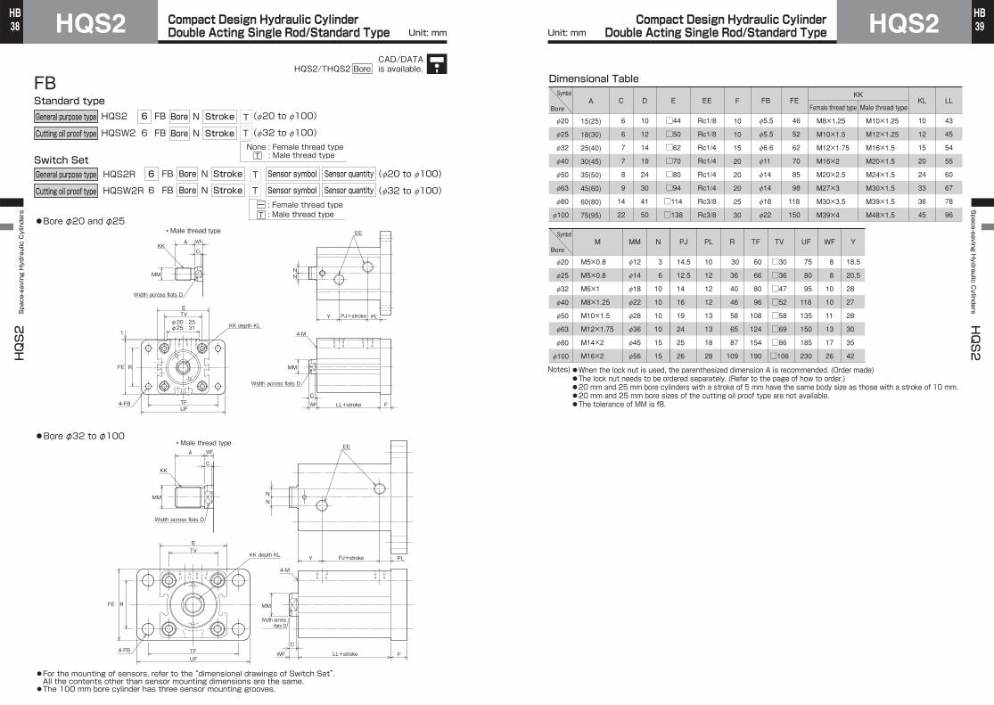
●When the lock nut is used, the parenthesized dimension A is recommended. (Order made)●The lock nut needs to be ordered separately. (Refer to the page of how to order.)●20 mm and 25 mm bore cylinders with a stroke of 5 mm have the same body size as those with a stroke of 10 mm.●20 mm and 25 mm bore sizes of the cutting oil proof type are not available.●The tolerance of MM is f8.
SD
HQS2W 6 SD Bore N Stroke
HQSW2 6 SD Bore N Stroke
General purpose type
Cutting oil proof type
T
T
For the mounting of sensors, refer to the “dimensional drawings of Switch Set”. All the contents other than sensor mounting dimensions are the same.The 100 mm bore cylinder has three sensor mounting grooves.
(f20 to f100)
(f32 to f100)
Bore φ20 and φ25
Switch SetHQS2R StrokeBore N
HQSW2R StrokeBore N
Sensor quantity
Sensor quantity
Sensor symbol
Sensor symbol
6
6
General purpose type
Cutting oil proof type
SD
SD
T
T
Standard type
(f20 to f100)
(f32 to f100)
None : Female thread type: Male thread type
: Female thread type: Male thread type
NN
Y PL
WF
KK
MM
WFA
C
Width across flats D
KK depth KL
MM
Width across flats D
EE
E
TVC
FF
AE
DE
MM
WFA
C
2
PLPJ+stroke
PJ+stroke
Y
LL+stroke
Width across flats D
φ20:25φ25:31
• Male thread type
• Male thread type
KK
MM
EE
Width across flats D
KK depth KL
WF
NN
LF+stroke
LL+strokeLF+stroke
ETV
4-FB through2×4 spot facing dia. FG depth BT
4-FB through2×4 spot facing dia. FG depth BT
C
• Port G thread type
• Port G thread type
FF
AE
DE
T
ー T
●
Bore φ32 to φ100●
●
●
Unit: mm Unit: mm
CAD/DATAis available.HQS2/THQS2 Bore

Compact Design Hydraulic CylinderDouble Acting Single Rod/Standard TypeHQS2
HQS2 Space-saving Hydraulic Cylinders
34HB Compact Design Hydraulic Cylinder
Double Acting Single Rod/Standard Type HQS2Space-saving H
ydraulic Cylinders
HQS2
35HB
HQS2W 6 LD Bore N Stroke
HQSW2 6 LD Bore N Stroke
General purpose type
Cutting oil proof type
LD
T
T
4-SB
PKPJ+strokeFP
LL+strokeSYSS+strokeXS
ZB+stroke
LL+strokeSS+strokeZB+stroke
STLH
EH
TSUS
E
NN
KK depth KL
MM
WC
A WC
EE
KK
Width across flats D
Width across flats D
Width across flats D
LF+stroke
MM
• Male thread type
• Male thread type
SU SU
2φ20:25 φ25:31
4-SBUS
PKFP
SYXSWTS
STLH
EH
E
EE
NN
PJ+stroke
MM
C
LF+strokeKK depth KL
CWA
Width across flats D
KK
MM
SU SU
(f20 to f100)
(f32 to f100)
Switch Set
Standard type
HQS2R StrokeBore N
HQSW2R StrokeBore N
Sensor quantity
Sensor quantity
Sensor symbol
Sensor symbol
6
6
LD
LD
T
T
(f20 to f100)
(f32 to f100)
None : Female thread type: Male thread typeT
: Female thread type: Male thread type
ー T
General purpose type
Cutting oil proof type
●Bore φ20 and φ25
●Bore φ32 to φ100
●For the mounting of sensors, refer to the “dimensional drawings of Switch Set”.All the contents other than sensor mounting dimensions are the same.*When installing the cylinder on the grounding surface, be sure to use hex. socket head cap screws.●The 100 mm bore cylinder has three sensor mounting grooves.
Dimensional TableSymbol
Bore
f20
f25
f32
f40
f50
f63
f80
f100
A
15(25)
18(30)
25(40)
30(45)
35(50)
45(60)
60(80)
75(95)
C
6
6
7
7
8
9
14
22
D
10
12
14
19
24
30
41
50
E
□44
□50
□62
□70
□80
□94
□114
□138
EE
Rc1/8
Rc1/8
Rc1/4
Rc1/4
Rc1/4
Rc1/4
Rc3/8
Rc3/8
EH
46
52
66
72.5
85
97
117
140
KL
10
12
15
20
24
33
36
45
LF
73
75
94
95
110
117
138
166
M8×1.25
M10×1.5
M12×1.75
M16×2
M20×2.5
M27×3
M30×3.5
M39×4
M10×1.25
M12×1.25
M16×1.5
M20×1.5
M24×1.5
M30×1.5
M39×1.5
M48×1.5
KK
Symbol
Bore
f20
f25
f32
f40
f50
f63
f80
f100
LL
43
45
54
55
60
67
78
96
MM
f12
f14
f18
f22
f28
f36
f45
f56
SB
6.6
6.6
9
11
14
16
18
22
FP
33.5
35.5
48
47
53
55
65
77
LH
24±0.15
27±0.15
35±0.15
37.5±0.15
45±0.15
50±0.15
60±0.25
71±0.25
ST
12
12
16
20
24
30
35
43
SU
15
15
20
20
25
25
30
35
SY
7.5
7.5
10
10
12.5
12.5
15
17.5
TS
58
64
79
90
104
121
144
174
US
70
76
94
108
126
146
172
208
W
8
8
10
10
11
13
17
26
XS
15.5
15.5
20
20
23.5
25.5
32
43.5
ZB
81
83
104
105
121
130
155
192
SS
58
60
74
75
85
92
108
131
N
3
6
10
10
10
10
15
15
PJ
14.5
12.5
14
16
19
24
25
26
PK
25
27
32
32
38
38
48
63
Notes)●When the lock nut is used, the parenthesized dimension A is recommended. (Order made)●The lock nut needs to be ordered separately. (Refer to the page of how to order.)●20 mm and 25 mm bore cylinders with a stroke of 5 mm have the same body size as those with a stroke of 10 mm.●20 mm and 25 mm bore sizes of the cutting oil proof type are not available.●The tolerance of MM is f8.
Female thread type Male thread type
Unit: mm Unit: mm
CAD/DATAis available.HQS2/THQS2 Bore

Compact Design Hydraulic CylinderDouble Acting Single Rod/Standard TypeHQS2
HQS2 Space-saving Hydraulic Cylinders
36HB Compact Design Hydraulic Cylinder
Double Acting Single Rod/Standard Type HQS2Space-saving H
ydraulic Cylinders
HQS2
37HB
FA
HQS2W 6 FA
HQSW2 6 FA
General purpose type
Cutting oil proof type
●Bore φ20 and φ25
●Bore φ32 to φ100
Switch Set
Standard typeBore N Stroke
Bore N Stroke
T
T
(f20 to f100)
(f32 to f100)
None : Female thread type: Male thread typeT
HQS2R StrokeBore N
HQSW2R StrokeBore N
Sensor quantity
Sensor quantity
Sensor symbol
Sensor symbol
6
6
FA
FA
T
T
(f20 to f100)
(f32 to f100)
General purpose type
Cutting oil proof type
: Female thread type: Male thread type
ー T
TF
UF
RFE
TVE
MM
A W
C
PLPJ+strokeY
LL+strokeF
Width across flats D
KK
4-MMM
4-FB
EE
Width across flats D
KK depth KL
NN
W
C
1φ20:25φ25:31
RFE
NN
Y PJ+stroke PL
W F LL+strokeTFUF
TV4-FB
E
4-M
KK
WA
C
Width across flats D
MM
EE
KK depth KL
MM
C
●For the mounting of sensors, refer to the “dimensional drawings of Switch Set”.All the contents other than sensor mounting dimensions are the same.●The 100 mm bore cylinder has three sensor mounting grooves.
• Male thread type
• Male thread type
Width across flats D
Dimensional TableSymbol
Bore
f20
f25
f32
f40
f50
f63
f80
f100
A
15(25)
18(30)
25(40)
30(45)
35(50)
45(60)
60(80)
75(95)
C
6
6
7
7
8
9
14
22
F
10
10
15
20
20
20
25
30
D
10
12
14
19
24
30
41
50
E
□44
□50
□62
□70
□80
□94
□114
□138
EE
Rc1/8
Rc1/8
Rc1/4
Rc1/4
Rc1/4
Rc1/4
Rc3/8
Rc3/8
FB
f5.5
f5.5
f6.6
f11
f14
f14
f18
f22
FE
46
52
62
70
85
98
118
150
KL
10
12
15
20
24
33
36
45
LL
43
45
54
55
60
67
78
96
M8×1.25
M10×1.5
M12×1.75
M16×2
M20×2.5
M27×3
M30×3.5
M39×4
M10×1.25
M12×1.25
M16×1.5
M20×1.5
M24×1.5
M30×1.5
M39×1.5
M48×1.5
KK
Symbol
Bore
f20
f25
f32
f40
f50
f63
f80
f100
M
M5×0.8
M5×0.8
M6×1
M8×1.25
M10×1.5
M12×1.75
M14×2
M16×2
MM
f12
f14
f18
f22
f28
f36
f45
f56
N
3
6
10
10
10
10
15
15
PJ
14.5
12.5
14
16
19
24
25
26
PL
10
12
12
12
13
13
18
28
R
30
36
40
46
58
65
87
109
TF
60
66
80
96
108
124
154
190
TV
□30
□36
□47
□52
□58
□69
□86
□106
UF
75
80
95
118
135
150
185
230
W
8
8
10
10
11
13
17
26
Y
18.5
20.5
28
27
28
30
35
42
Notes) ●When the lock nut is used, the parenthesized dimension A is recommended. (Order made)●The lock nut needs to be ordered separately. (Refer to the page of how to order.)●20 mm and 25 mm bore cylinders with a stroke of 5 mm have the same body size as those with a stroke of 10 mm.●20 mm and 25 mm bore sizes of the cutting oil proof type are not available.●The tolerance of MM is f8.
Female thread type Male thread type
Unit: mm Unit: mm
CAD/DATAis available.HQS2/THQS2 Bore
Compact Design Hydraulic CylinderDouble Acting Single Rod/Standard TypeHQS2
HQS2 Space-saving Hydraulic Cylinders
38HB Compact Design Hydraulic Cylinder
Double Acting Single Rod/Standard Type HQS2Space-saving H
ydraulic Cylinders
HQS2
39HB
Dimensional TableSymbol
Bore
f20
f25
f32
f40
f50
f63
f80
f100
A
15(25)
18(30)
25(40)
30(45)
35(50)
45(60)
60(80)
75(95)
C
6
6
7
7
8
9
14
22
D
10
12
14
19
24
30
41
50
E
□44
□50
□62
□70
□80
□94
□114
□138
EE
Rc1/8
Rc1/8
Rc1/4
Rc1/4
Rc1/4
Rc1/4
Rc3/8
Rc3/8
FB
f5.5
f5.5
f6.6
f11
f14
f14
f18
f22
FE
46
52
62
70
85
98
118
150
KL
10
12
15
20
24
33
36
45
LL
43
45
54
55
60
67
78
96
M8×1.25
M10×1.5
M12×1.75
M16×2
M20×2.5
M27×3
M30×3.5
M39×4
M10×1.25
M12×1.25
M16×1.5
M20×1.5
M24×1.5
M30×1.5
M39×1.5
M48×1.5
KK
Female thread type Male thread type
Symbol
Bore
f20
f25
f32
f40
f50
f63
f80
f100
M
M5×0.8
M5×0.8
M6×1
M8×1.25
M10×1.5
M12×1.75
M14×2
M16×2
MM
f12
f14
f18
f22
f28
f36
f45
f56
N
3
6
10
10
10
10
15
15
PL
10
12
12
12
13
13
18
28
R
30
36
40
46
58
65
87
109
TF
60
66
80
96
108
124
154
190
TV
□30
□36
□47
□52
□58
□69
□86
□106
UF
75
80
95
118
135
150
185
230
WF
8
8
10
10
11
13
17
26
F
10
10
15
20
20
20
25
30
Y
18.5
20.5
28
27
28
30
35
42
PJ
14.5
12.5
14
16
19
24
25
26
Notes)●When the lock nut is used, the parenthesized dimension A is recommended. (Order made)●The lock nut needs to be ordered separately. (Refer to the page of how to order.)●20 mm and 25 mm bore cylinders with a stroke of 5 mm have the same body size as those with a stroke of 10 mm.●20 mm and 25 mm bore sizes of the cutting oil proof type are not available.●The tolerance of MM is f8.
FB
HQS2W 6 FB
HQSW2 6 FB
Switch Set
Standard type
HQS2R
HQSW2R
6
6
FB
FB
TFUF
RFE
TVE
MM
WFA
C
PLY
LL+stroke
LL+stroke
F
Width across flats D
KK
MM
4-FB
EE
Width across flats D
KK depth KL4-M
WF
NN
C
1
φ20:25φ25:31
RFE
NN
Y PL
WFTFUF
TV
4-FB
E
4-M
KK
MM
WFA
C
Width across flats D
F
KK depth KL
MM
EE
C
General purpose type
Cutting oil proof type
General purpose type
Cutting oil proof type
●Bore φ20 and φ25
Bore N Stroke
Bore N Stroke
T
T
(f20 to f100)
(f32 to f100) None : Female thread type
: Male thread typeT
StrokeBore N
StrokeBore N
Sensor quantity
Sensor quantity
Sensor symbol
Sensor symbol
T
T
(f20 to f100)
(f32 to f100)
●Bore φ32 to φ100
: Female thread type: Male thread type
ー T
• Male thread type
• Male thread type
●For the mounting of sensors, refer to the “dimensional drawings of Switch Set”. All the contents other than sensor mounting dimensions are the same.●The 100 mm bore cylinder has three sensor mounting grooves.
Width across flats D
PJ+stroke
PJ+stroke
Unit: mm Unit: mm
CAD/DATAis available.HQS2/THQS2 Bore

Compact Design Hydraulic CylinderDouble Acting Double Rod/Standard TypeHQS2
HQS2 Space-saving Hydraulic Cylinders
40HB Compact Design Hydraulic Cylinder
Double Acting Double Rod/Standard Type HQS2Space-saving H
ydraulic Cylinders
HQS2
41HB
Dimensional TableSymbol
Bore
f20
f25
f32
f40
f50
f63
f80
f100
AE
8
8
8
8
12
12
12
12
A
15(25)
18(30)
25(40)
30(45)
35(50)
45(60)
60(80)
75(95)
BT
5.4
5.4
6.5
8.6
10.8
13
15.2
17.5
D
10
12
14
19
24
30
41
50
DE
f17.2
f17.2
f17.2
f17.2
f21.5
f21.5
f21.5
f25.5
E
□44
□50
□62
□70
□80
□94
□114
□138
EE
Rc1/8
Rc1/8
Rc1/4
Rc1/4
Rc1/4
Rc1/4
Rc3/8
Rc3/8
FB
f5.5
f5.5
f6.6
f9
f11
f14
f16
f18
FF
G1/8
G1/8
G1/8
G1/8
G1/4
G1/4
G1/4
G3/8
FG
f9.5
f9.5
f11
f14
f17.5
f20
f23
f26
KL
10
12
15
20
24
33
36
45
M8×1.25
M10×1.5
M12×1.75
M16×2
M20×2.5
M27×3
M30×3.5
M39×4
M10×1.25
M12×1.25
M16×1.5
M20×1.5
M24×1.5
M30×1.5
M39×1.5
M48×1.5
Female thread type Male thread type
Symbol
Bore
f20
f25
f32
f40
f50
f63
f80
f100
MM
f12
f14
f18
f22
f28
f36
f45
f56
N
Rc thread
3
6
10
10
10
10
15
15
G thread Rc thread G thread Rc thread G thread
3
6
10
10
14
16
19
18
17
15
16
18
19
22
25
24
17
15
16
18
19
22
23
24
YWF
8
8
10
10
11
13
17
26
TV
□30
□36
□47
□52
□58
□69
□86
□106
18.5
20.5
28
27
28
30
35
42
18.5
20.5
28
27
28
30
36
42
C
6
6
7
7
8
9
14
22
LL
54
56
72
72
75
82
95
108
KK
PJ
Notes)●When the lock nut is used, the parenthesized dimension A is recommended. (Order made)●The lock nut needs to be ordered separately. (Refer to the page of how to order.)●20 mm and 25 mm bore cylinders with a stroke of 5 mm have the same body size as those with a stroke of 10 mm.●20 mm and 25 mm bore sizes of the cutting oil proof type are not available.●The tolerance of MM is f8.
SD
HQS2DW 6 SD
HQSW2D 6 SD
Switch Set
Standard type
HQS2RD
HQSW2RD
6
6
SD
SD
Bore N Stroke
Bore N Stroke
General purpose type
Cutting oil proof type
T
T
(f20 to f100)
(f32 to f100)
StrokeBore N
StrokeBore N
Sensor quantity
Sensor quantity
Sensor symbol
Sensor symbol
T
T
(f20 to f100)
(f32 to f100)
None : Female thread type: Male thread typeT
: Female thread type: Male thread type
ー T
General purpose type
Cutting oil proof type
MM
WFA
C
Width across flats D
KK
KK depth KL
ETV
4-FB through 2×4-spot facing dia. FG depth BT
4-FB through 2×4-spot facing dia. FG depth BT
MMMM
Width across flats D
WF
Y
EE
Y
NN
C
• Male thread type
KK depth KL
V-shapedround groove
C
•Port G thread type
•Port G thread type
FF
AE
DE
2
φ20:25φ25:31
NN
KK
WFA
C
Width across flats D
KK depth KL
ETV
WF WF+stroke
WF+stroke
EE
Y
MMMM
Y
Width across flats D
C C
MM
• Male thread type
KK depth KL
FF
AE
DE
●Bore φ20 and φ25
●Bore φ32 to φ100
PJ+stroke
LL+stroke
PJ+stroke
LL+stroke
V-shapedround groove
●The surface without V-shaped round grooves on the end face is the mounting surface.●For the mounting of sensors, refer to the “dimensional drawings of Switch Set”.All the contents other than sensor mounting dimensions are the same.●The 100 mm bore cylinder has three sensor mounting grooves.
Unit: mm Unit: mm
CAD/DATAis available.HQS2/THQS2 Bore
Compact Design Hydraulic CylinderDouble Acting Double Rod/Standard TypeHQS2
HQS2 Space-saving Hydraulic Cylinders
42HB Compact Design Hydraulic Cylinder
Double Acting Double Rod/Standard Type HQS2Space-saving H
ydraulic Cylinders
HQS2
43HB
Dimensional TableSymbol
Bore
f20
f25
f32
f40
f50
f63
f80
f100
A
15(25)
18(30)
25(40)
30(45)
35(50)
45(60)
60(80)
75(95)
C
6
6
7
7
8
9
14
22
D
10
12
14
19
24
30
41
50
E
□44
□50
□62
□70
□80
□94
□114
□138
EE
Rc1/8
Rc1/8
Rc1/4
Rc1/4
Rc1/4
Rc1/4
Rc3/8
Rc3/8
EH
46
52
66
72.5
85
97
117
140
KL
10
12
15
20
24
33
36
45
LG
84
86
112
112
125
132
155
178
M8×1.25
M10×1.5
M12×1.75
M16×2
M20×2.5
M27×3
M30×3.5
M39×4
M10×1.25
M12×1.25
M16×1.5
M20×1.5
M24×1.5
M30×1.5
M39×1.5
M48×1.5
KK
Symbol
Bore
f20
f25
f32
f40
f50
f63
f80
f100
LZ
54
56
72
72
75
82
95
108
MM
f12
f14
f18
f22
f28
f36
f45
f56
SB
6.6
6.6
9
11
14
16
18
22
N
3
6
10
10
10
10
15
15
PJ
17
15
16
18
19
22
25
24
FP
33.5
35.5
48
47
53
55
65
77
LH
24±0.15
27±0.15
35±0.15
37.5±0.15
45±0.15
50±0.15
60±0.25
71±0.25
ST
12
12
16
20
24
30
35
43
SU
15
15
20
20
25
25
30
35
SV
69
71
92
92
100
107
125
143
TS
58
64
79
90
104
121
144
174
US
70
76
94
108
126
146
172
208
W
8
8
10
10
11
13
17
26
XS
15.5
15.5
20
20
23.5
25.5
32
43.5
ZZ
100
102
132
132
147
158
189
230
Notes)●When the lock nut is used, the parenthesized dimension A is recommended. (Order made)●The lock nut needs to be ordered separately. (Refer to the page of how to order.)●20 mm and 25 mm bore cylinders with a stroke of 5 mm have the same body size as those with a stroke of 10 mm.●20 mm and 25 mm bore sizes of the cutting oil proof type are not available.●The tolerance of MM is f8.
Female thread type Male thread type
LD
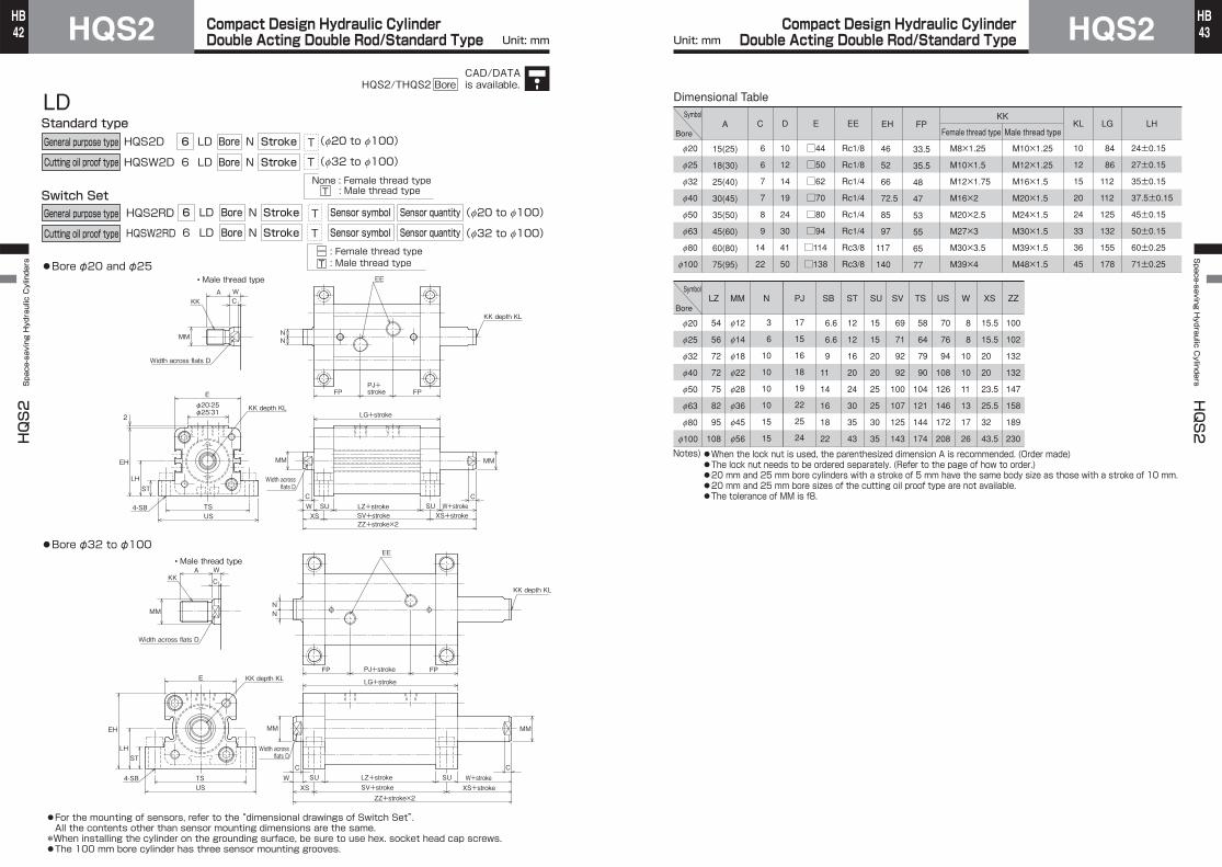
HQS2DW 6 LD
HQSW2D 6 LD
Switch Set
Standard type
HQS2RD
HQSW2RD
6
6
LD
LD
●Bore φ20 and φ25
●Bore φ32 to φ100
●For the mounting of sensors, refer to the “dimensional drawings of Switch Set”. All the contents other than sensor mounting dimensions are the same.
*When installing the cylinder on the grounding surface, be sure to use hex. socket head cap screws.●The 100 mm bore cylinder has three sensor mounting grooves.
4-SB
FP
SUSUXS
STLH
EH
TSUS
E
MM MM
LZ+stroke W+strokeCC
WXS+strokeSV+stroke
ZZ+stroke×2
FPPJ+stroke
NN
EE
KK depth KLLG+stroke
A WCKK
Width across flats D
KK depth KL
MM
• Male thread type
2
φ20:25φ25:31
4-SBUS
FP
XSW SUSUTS
STLH
EH
E
EE
NN
PJ+stroke
MM
C
MM
CW+strokeLZ+strokeXS+strokeSV+stroke
ZZ+stroke×2
FPKK depth KL LG+stroke
C
WA
Width across flats D
KK
KK depth KL
MM
• Male thread type
Bore N Stroke
Bore N Stroke
General purpose type
Cutting oil proof type
General purpose type
Cutting oil proof type
T
T
(f20 to f100)
(f32 to f100)
StrokeBore N
StrokeBore N
Sensor quantity
Sensor quantity
Sensor symbol
Sensor symbol
T
T
(f20 to f100)
(f32 to f100)
None : Female thread type: Male thread typeT
: Female thread type: Male thread type
ー T
Width across flats D
Width across flats D
Unit: mm Unit: mm
CAD/DATAis available.HQS2/THQS2 Bore

Compact Design Hydraulic CylinderDouble Acting Double Rod/Standard TypeHQS2
HQS2 Space-saving Hydraulic Cylinders
44HB Compact Design Hydraulic Cylinder
Double Acting Double Rod/Standard Type HQS2Space-saving H
ydraulic Cylinders
HQS2
45HB
FA
HQS2DW 6 FA
HQSW2D 6 FA
Switch Set
Standard type
HQS2RD
HQSW2RD
6
6
FA
FA
MMMM
4-M
FW
MM
W(WF)A
C
Y
Width across flats D
KK
EE
Y
TF
UF
RFE
TV
E
4-FB
KK depth KL
NN
CC
• Male thread type
• Male thread type
KK depth KL
1
φ20:25φ25:31
NN
FE R
LL+strokeFW WF+stroke
MM
EE
PJ+strokeY
KK
W(WF)
Width across flats D
C
A
MMMM
4-M
Y
4-FB
TV
UFTF
KK depth KLE
C C
KK depth KL
●For the mounting of sensors, refer to the “dimensional drawings of Switch Set”. All the contents other than sensor mounting dimensions are the same.●The 100 mm bore cylinder has three sensor mounting grooves.
StrokeBore N
StrokeBore N
Sensor quantity
Sensor quantity
Sensor symbol
Sensor symbol
T
T
(f20 to f100)
(f32 to f100)
None : Female thread type: Male thread typeT
: Female thread type: Male thread type
ー T
General purpose type
Cutting oil proof type
General purpose type
Cutting oil proof type
Bore N Stroke
Bore N Stroke
T
T
(f20 to f100)
(f32 to f100)
●Bore φ20 and φ25
●Bore φ32 to φ100
Width across flats D
Width across flats D
PJ+stroke
LL+strokeWF+stroke
Dimensional TableSymbol
Bore
f20
f25
f32
f40
f50
f63
f80
f100
A
15(25)
18(30)
25(40)
30(45)
35(50)
45(60)
60(80)
75(95)
C
6
6
7
7
8
9
14
22
F
10
10
15
20
20
20
25
30
D
10
12
14
19
24
30
41
50
E
□44
□50
□62
□70
□80
□94
□114
□138
EE
Rc1/8
Rc1/8
Rc1/4
Rc1/4
Rc1/4
Rc1/4
Rc3/8
Rc3/8
FB
f5.5
f5.5
f6.6
f11
f14
f14
f18
f22
FE
46
52
62
70
85
98
118
150
KL
10
12
15
20
24
33
36
45
LL
54
56
72
72
75
82
95
108
M8×1.25
M10×1.5
M12×1.75
M16×2
M20×2.5
M27×3
M30×3.5
M39×4
M10×1.25
M12×1.25
M16×1.5
M20×1.5
M24×1.5
M30×1.5
M39×1.5
M48×1.5
KK
Symbol
Bore
f20
f25
f32
f40
f50
f63
f80
f100
M
M5×0.8
M5×0.8
M6×1
M8×1.25
M10×1.5
M12×1.75
M14×2
M16×2
MM
f12
f14
f18
f22
f28
f36
f45
f56
R
30
36
40
46
58
65
87
109
N
3
6
10
10
10
10
15
15
PJ
17
15
16
18
19
22
25
24
TF
60
66
80
96
108
124
154
190
TV
□30
□36
□47
□52
□58
□69
□86
□106
UF
75
80
95
118
135
150
185
230
W
8
8
10
10
11
13
17
26
WF
8
8
10
10
11
13
17
26
Y
18.5
20.5
28
27
28
30
35
42
Notes) ●When the lock nut is used, the parenthesized dimension A is recommended. (Order made)●The lock nut needs to be ordered separately. (Refer to the page of how to order.)●20 mm and 25 mm bore cylinders with a stroke of 5 mm have the same body size as those with a stroke of 10 mm.●20 mm and 25 mm bore sizes of the cutting oil proof type are not available.●The tolerance of MM is f8.
Female thread type Male thread type
Unit: mm Unit: mm
CAD/DATAis available.HQS2/THQS2 Bore

Compact Design Hydraulic CylinderDouble Acting Double Rod/Standard TypeHQS2
HQS2 Space-saving Hydraulic Cylinders
46HB Compact Design Hydraulic Cylinder
Double Acting Double Rod/Standard Type HQS2Space-saving H
ydraulic Cylinders
HQS2
47HB
Switch SetHQS2R(D) StrokeBore N
HQSW2R(D) StrokeBore N
Sensor quantity
Sensor quantity
Sensor symbol
Sensor symbol
6
6
●Bore φ32 to φ100
Single rod
Double rod
Single rod
Double rod
Mounting style
Mounting style
●The side without V-shaped round grooves on the end face corresponds to UX1.
T
T: Female thread type: Male thread type
ー T
General purpose type
Cutting oil proof type
●Bore φ20 and φ25
UX2UX1
RVRV
Rear wiringT type
Upper wiringT type
Rear wiringT type
Upper wiringT type
RV
UX2
V-shapedround groove
V-shapedround groove
UX1
RV
RV
UX2UX1
Rear wiringAX type
Upper wiringAZ type
Rear wiringAX type
Upper wiringAZ type
RV
UX1 UX2
RVRV
●The 100 mm bore cylinder has three sensor mounting grooves.
●The 100 mm bore cylinder has three sensor mounting grooves.●The side without V-shaped round grooves on the end face corresponds to UX1.
Note) Dimension UX is for reference only. For details, refer to the sensor mountable minimum stroke table.
Operating Range and Hysteresis
General purpose typeDimensional Table (T/AX/AZ type)
●Rear wiringAX205W(solid state sensor)
●Upper wiring AZ205W(solid state sensor)
If the sensor cannot bemounted as shown above, use the upper wiring type.
Notes)
Dimensional TableCutting oil proof type
Sensor Attachment Dimensions
*The 100 mm bore cylinder has mounting grooves in three surfaces.
WR525(reed sensor)WS235-1(solid state sensor)
WR535(reed sensor)WS245-1(solid state sensor)
T0H・T5HT2H・T3H
T0V・T5VT2V・T3V
T2YH T2YV AX AZ
RV
AX1**・AZ1**Operating
range Hysteresis Operating range Hysteresis Operating
range Hysteresis Operating range Hysteresis Operating
range Hysteresis Operating range Hysteresis Operating
range Hysteresis Operating range Hysteresis
-
10 to 17
6 to 14
-
2 or less
T type
Reed sensor
3 to 10
-
2 or less
-
-
2 or less
3 to 8
-
1 or less
-
5 to 10
-
1 or less
-
WR type
-
10 to 17
7 to 15
-
2 or less
2.5 or less
AX2**・AZ2**
-
4 to 8
6 to 9
-
1 or less
AX*W・AZ*W
-
15 to 22
19 to 25
T2/T3 type
Solid state sensor
T2Y type WS type
-
12 to 15
19 to 25
-
2 or less
f20
f25
f32
f40
f50
f63
f80
f100
Bore
T
22
25
------
26
29
------
28
31
------
31
34
------
--
--
13
14
------
--19
20
22
24
30
36
--19
20
22
24
30
36
13
14
------
--19
20
22
24
30
36
--19
20
22
24
30
36
12
13
------
--17
17
20
25
30
42
--17
17
20
25
30
42
23
24
------
--35
34
35
40
47
53
--35
34
35
40
47
53
AX AZ T AX AZ T AX AZ T AX AZ
UX1
Single rod Double rod Single rod Double rod
UX2
44
48
53
61
70
83.5
37
41
46
54
63
76.5
Relief bybending radius
R25 or more
f20
f25
f32
f40
f50
f63
f80
f100
Bore
f32
f40
f50
f63
f80
f100
Bore
37
41
46
54
63
76.5
RV
Rear wiring Upper wiring Rear wiring Upper wiring
AX*W
53
57
62
69
79
91.5
WR・WS
44
48
53
61
70
83.5
AZ*W
53
57
62
69
79
91.5
WR・WS
74
82
92
108
126
153
RY UX1
WRAX*WAZ*W
WSAX*WAZ*W
WR WS
UX2
AX*W
106
114
124
138
158
183
WR・WS
88
96
106
122
140
167
AZ*W
106
114
124
138
158
183
13(13)14(14)16(16)17(17)22(22)27(27)
11(11)17(17)19(19)20(20)25(25)33(33)
15(15)20(20)21(21)24(24)29(29)35(35)
11(29)11(28)14(29)18(33)22(39)33(44)
12(28)14(33)16(35)21(36)25(43)40(50)
16(32)16(36)20(37)23(40)29(47)41(52)
WR・WS
RVRVRY
RVRVRY
RVRVRY
RVRVRY
●Ensure that the bending radius of the flexible tube is R25 or more.If the bending radius is smaller, the wire may be broken.●The parenthesized values apply to the double rod cylinders.
Unit: mm Unit: mm

Compact Design Hydraulic CylinderHQS2HQS2 Space-saving Hydraulic Cylinders
48HB
Compact Design Hydraulic Cylinder HQS2Space-saving H
ydraulic Cylinders
HQS2
49HB
A82
A81A54
Bore
f20
f25
f32
f40
f50
f63
f80
f100
A
15
18
25
30
35
45
60
75
A1
4
4
4
4
4
4
4
4
DN
2
2
2
2
2
2
2
2
KP
1.25
1.25
1.5
1.5
1.5
1.5
1.5
1.5
KM
10
12
16
20
24
30
39
48
* MM
f12
f14
f18
f22
f28
f36
f45
f56
L
0
0
0
0
0
0
0
0
* S
10
12
14
19
24
30
41
50
WF
8
8
10
10
11
13
17
26
Table of Basic Dimensions
Bore
f20
f25
f32
f40
f50
f63
f80
f100
f12
f14
f18
f22
f28
f36
f45
f56
10
12
14
19
24
30
41
50
8
10
12
16
20
27
30
39
1.25
1.5
1.75
2
2.5
3
3.5
4
10
12
15
20
24
33
36
45
8
8
10
10
11
13
17
26
0
0
0
0
0
0
0
0
2
2
2
2
2
2
2
2
A DN FWPKMK L
Table of Basic Dimensions
Table of Basic Dimensions (Standard dimensions)
Bore
f40
f50
f63
f80
*A
25
25
25
30
*A1+0.5+0.3
12.5
12.5
12.5
15
*A2-0.2-0.3
12.5
12.5
12.5
15
*DM-0.1-0.4
f18
f22
f28
f36
*DP-0.2-0.3
f13
f16
f21
f26
*DR
1.0
1.5
1.5
2.0
*MM
f22
f28
f36
f45
W
35
35
40
45
WF
35
35
40
45
Table of Basic Dimensions (Standard dimensions)
Bore
f20
f25
f32
f40
f50
f63
f80
f100
*A
25
25
25
25
25
30
30
40
*A1+0.5+0.3
12.5
12.5
12.5
12.5
12.5
15
15
20
*A2-0.2-0.3
12.5
12.5
12.5
12.5
12.5
15
15
20
*DM
f12
f14
f18
f22
f28
f36
f45
f56
*DP-0.2-0.3
f8
f10
f13
f16
f21
f26
f31
f38
*DR
0.5
0.5
1.0
1.5
1.5
2.0
2.0
3.0
*MM
f12
f14
f18
f22
f28
f36
f45
f56
W
20
20
30
35
35
40
45
55
WFSD/FBstyle
FAstyle
SD/FBstyle
FAstyle
20
20
30
35
35
40
45
55
A83Connecting accessories(M-end) are also available.
●The *-marked dimension is fixed.●If it is necessary to change the fixed dimension, consult us.
* MM * S*
*
15°15°
*A*A1
FA=WSD・FB=WF*A2
*MM
C0.2
*DR
*DM *DP
33 15°
*A
φ40 to φ80
*A1FA=WSD・FB=WF*A2
*MM
C1
C0.2
*DR
*DM *DP
3
Width across flats*S
Width across flats*SKM×KP
*MM
*A1
WFA
L
KM×KP
*MM
315°
WF
L
A
No. of chamfered surfaces DN No. of chamfered
surfaces DNHow to order
Semi-standardsymbol
Dimension symbol (Specify only when the dimensiondiffers from the basic dimension.)
Series Model number
Example A83
KM and KP need to be specified as a pair.
Bore φ40, rod end shape: A83, WF=60HQS2 6SD40N50T-X A83WF-60
15°
*A
φ40 to φ80
*A1FA=W SD・FB=WF*A2
*MM
C1
C0.2
*DR
*DM *DP
3
Note) In the case of this shape, only dimension WF can be changed.
WF
8
8
10
10
11
13
17
26
Special Rod End ShapesA00(T)
A51
f12
f14
f18
f22
f28
f36
f45
f56
Bore *MM
f20
f25
f32
f40
f50
f63
f80
f100
Table of Basic Dimensions
Change of Rod End Shape■You can specify the shape and dimension of the rod end as shownbelow using the semi-standard symbols and dimension symbols. (No need to specify the dimension symbol if you order a cylinderwith the basic dimensions. Specify only the semi-standard symbol.)
●The *-marked dimension is fixed.●If it is necessary to change the fixed dimension, consult us.
Note) Increase dimension WF by dimension L.
Table of Basic Dimensions
A53
f20
f25
f32
f40
f50
f63
f80
f100
f12
f14
f18
f22
f28
f36
f45
f56
10
12
16
20
24
30
39
48
1.25
1.25
1.5
1.5
1.5
1.5
1.5
1.5
15
18
25
30
35
45
60
75
8
8
10
10
11
13
17
26
10
12
14
19
24
30
41
50
Bore * MMKM KP FWA * S
Table of Basic Dimensions (Standard dimensions)
f20
f25
f32
f40
f50
f63
f80
f100
f12
f14
f18
f22
f28
f36
f45
f56
10
12
16
20
24
30
39
48
1.25
1.25
1.5
1.5
1.5
1.5
1.5
1.5
15
18
25
30
35
45
60
75
8
8
10
10
11
13
17
26
10
12
14
19
24
30
41
50
Bore * MMKM KP FWA * S
0
0
0
0
0
0
0
0
L
2
2
2
2
2
2
2
2
DN
Use this shape to move the width across flats S of ‘A00(T)’.
- X
15°
●
*MM
315°
WF
KM×KP
*φMM
*S
Width across flats
No. of chamfered surfaces DN
WFA
315°
L
Width across flats*S
A WF
*MM
KM×KP 3
Unit: mm Unit: mm
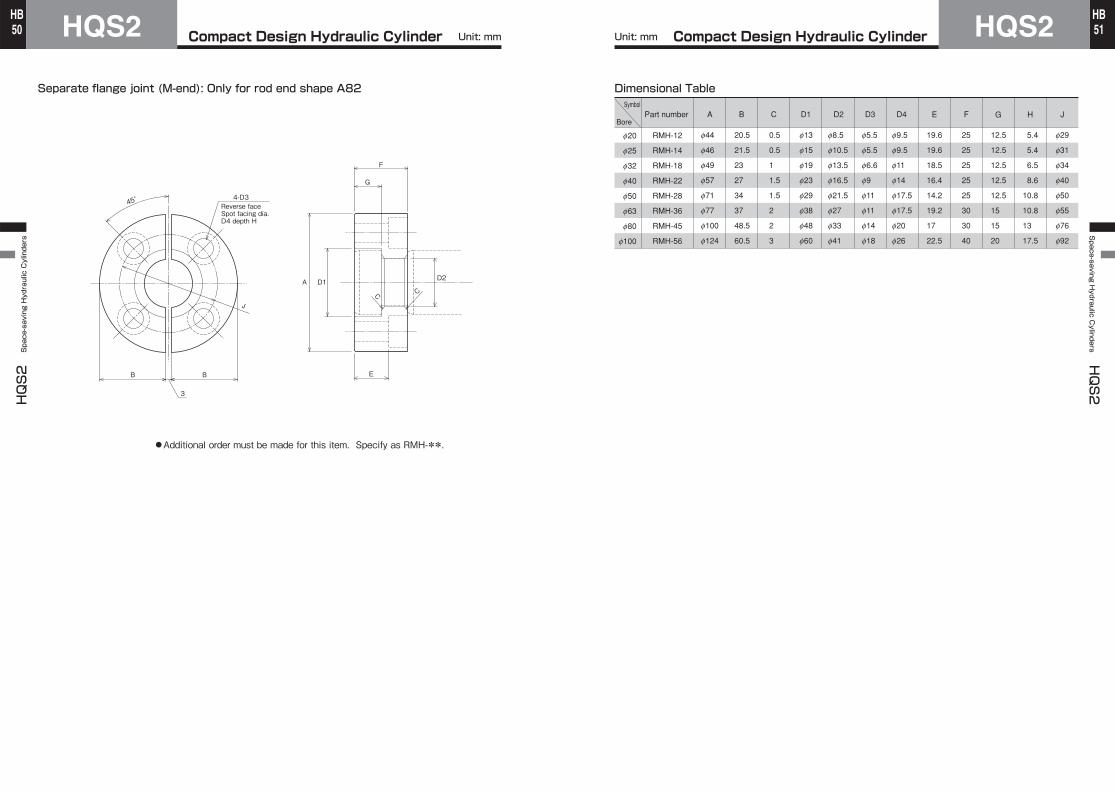
Compact Design Hydraulic CylinderHQS2HQS2 Space-saving Hydraulic Cylinders
50HB
Compact Design Hydraulic Cylinder HQS2Space-saving H
ydraulic Cylinders
HQS2
51HB
Reverse faceSpot facing dia. D4 depth H
4-D345°
B B
3
J
C C
D2D1A
F
G
E
Separate flange joint (M-end): Only for rod end shape A82
●Additional order must be made for this item. Specify as RMH-**.
Dimensional TableSymbol
Bore
f20
f25
f32
f40
f50
f63
f80
f100
RMH-12
RMH-14
RMH-18
RMH-22
RMH-28
RMH-36
RMH-45
RMH-56
f44
f46
f49
f57
f71
f77
f100
f124
Part number
20.5
21.5
23
27
34
37
48.5
60.5
BA
0.5
0.5
1
1.5
1.5
2
2
3
f13
f15
f19
f23
f29
f38
f48
f60
f8.5
f10.5
f13.5
f16.5
f21.5
f27
f33
f41
f5.5
f5.5
f6.6
f9
f11
f11
f14
f18
f9.5
f9.5
f11
f14
f17.5
f17.5
f20
f26
19.6
19.6
18.5
16.4
14.2
19.2
17
22.5
25
25
25
25
25
30
30
40
12.5
12.5
12.5
12.5
12.5
15
15
20
5.4
5.4
6.5
8.6
10.8
10.8
13
17.5
f29
f31
f34
f40
f50
f55
f76
f92
C D1 D2 D3 D4 E F G H J
Unit: mm Unit: mm

Compact Design Hydraulic CylinderHQS2HQS2 Space-saving Hydraulic Cylinders
52HB
Compact Design Hydraulic Cylinder HQS2Space-saving H
ydraulic Cylinders
HQS2
53HB
Precautions for use
When tightening the piston rod end screw of a double actingdouble rod cylinder, use the width across flats on the sideon which the screw is tightened. Since the piston rod of adouble rod type cylinder is fastened with screws, take carethat rotating force at both ends of the piston rod is notapplied to the rod.
Cylinder Mounting Bolt Tightening TorqueTightening torqueCylinder bore Mounting bolt size
4.8 4.8 5.914.028.049.077.0
120.0
Notes on disassembly and reassembly
f20f25f32f40f50f63f80
f100
M5×0.8 M5×0.8 M6×1 M8×1.25M10×1.5M12×1.75M14×2M16×2
Boref20 f25 f32 f40
8 8 10 12
5 5 8 10
46 58 70 85
a d PCDBoref50 f63 f80
f100
4 4 5 7
4 4 4 4
23 25 32 38
a d PCD
Unit: mm
Seal replacement
Components Combination ListNo. ① ②
Screw on bushWithout V-groove
With V-groove
Copper pieceRequired-
Set screw typeFlat point
Cone point
Note) A copper piece may havebeen set under the set screw.
●
●
●
●
*Cutting oil proof type: Bore φ32*General purpose type: Bore φ20 to φ100 Cutting oil proof type: Bore φ40 to φ100
φd depth a
PCD
5
φ28
Cone point set screw
V-groove
Flat point set screwCopper piece
Bush withoutV-groove
Bush withV- groove
① ②
After removing the set screw, use the turning hole of thebush to remove the bush from the cylinder. When a jig isremoved from the rod end screw, burrs may occur on the
width across flats of the rod. Remove the burrs with a file, etc. and remove the bush.The piston rod and piston cannot be disassembled.When reassembling the cylinder, be careful that foreign matters such as dust, fillings, and debris do not enter the inside of the cylinder.
●Dimensions of bush turning hole
●When using the cylinder with stroke adjuster tighten the screw(s) to the rod end completely so that no load is applied to the piston rod screw section.●Since side load (eccentric load) must not be applied to the piston rod, take care when installing the cylinder.●When operating the cylinder for the first time, discharge air from the piping. After discharging air, run the cylinder at a reduced pressure, and graduallyincrease the pressure to the working pressure.Note) Since HQS2 Series has no air vents, take air
bleeding from the piping.●To install the cylinder, use four hex. socket head cap screws (JIS B1176, strength class 10.9 or more).●When using mounting bolts, screw the bolts into mounting materials by 80% or more of the screw diameter. The material of the mounting materials must have strength equal to SS400.●When using nuts to tighten mounting bolts, use steel nuts with a strength class of 6 or more.(However, DO NOT use the type-3 nuts.)●When using mounting bolts to secure the cylinder body, be sure to tighten them according to the following specified torque.
●When a copper piece is equipped under the set screw to protect the bush, remove it before tightening the bush.●The center height of cylinders of the mounting style LD has been determined before shipment. When reassembling such a cylinder, adjust the center height.●After tightening the bush;In case of ①, place the copper piece under the set screw and tighten it.In case of ②, tighten the set screw without placing the copper piece.
●When disassembling the cylinder, replace all seals.●General purpose types (HQS2, HQS2D, HQS2R and HQS2RD): The piston seals, rod seals, dust wipers and bush O-rings are replaceable.●Cutting oil proof types (HQSW2, HQSW2D, HQSW2R and HQSW2RD): The piston seals, rod seals and bush O-rings are replaceable.The dust wiper 1 of any cutting oil proof type cylinder has been press-fitted into the bush, and is integrated with the bush. Although it can be removed, doing so may damage the bush. It is recommended to replace the bush as well when replacing the dust wiper. The dust wiper 1 is not included in the seal set. If it is necessary, separately make an order.●Since the piston and rod have been locked, the piton rod O-ring cannot be replaced.
Set screw(hex. wrench)
Turning hole
AX/AZ type sensor (φ32 to φ100)
WR/WS type bracket screw tightening torque:Approx 0.6 N・m
Note) If the tightening torque is improper, the sensor may be dislocated, or the sensor body may be damaged.
AX/AZ type bracket screw tightening torque: Approx. 0.4 N・m
Fit the sensor into the groove as shown left.Slide the sensor to any position. Installing in the center of operating rangeprovides the most stable detection.
To detect the cylinder stroke end, mount the sensorat dimension UX (optimum setting position).After sliding the sensor to the detectingposition, tighten the mounting screw.
Setting method of sensor detecting position
WR/WS type sensor (φ32 to φ100)
T type sensor (φ20 and φ25)
Torque of Mounting Screw
Sensor type
Nominal dia. of mounting screwMounting screwtightening tool
Precision slottedscrewdriver
Small-sizedPhillips-head screwdriver
Tightening torque
T0・T5・T2・T3
M2.5
Approx. 0.1 to 0.2 N・m
T2Y
M3
Approx. 0.4 N・m
Note) If the tightening torque is improper, the sensor maybe dislocated, or the sensor body may be damaged.
1.2.
3.
4.
Loosen the bracket screw, and fit the bracket in the center of the sensor.Insert the sensor combined with the bracket into the sensor mounting part of the cylinder body.Slide the sensor to any position. Installing in the center of operating range provides the most stable detection.To detect the cylinder stroke end, mount the sensor at dimension UX (optimum setting position).
1.2.3.4.After sliding the sensor to the detecting position, tighten the bracket screw.5.
Slide the sensor to
any position.
Mounting screw
Slide the sensor to
any position.
Hex. socket button head cap screw (hex. wrench: 2 mm)
Bracket (T10)Slide the sensor to
any position.
Bracket screw(M4)
Dent
Bracket(T07)