17730094 fired heaters
TRANSCRIPT
8/16/2019 17730094 Fired Heaters
http://slidepdf.com/reader/full/17730094-fired-heaters 1/141
Furnaces & Fired Heaters
This introduction to Fired Heater Design is presented to provide anoverview of the considerations and methods used in the thermal andmechanical design of furnaces and fired heaters for the Refining &Petrochemical Industry.
The formulas and correlations presented herein are all in the publicdomain and are to be used only as a learning tool. ou may copy
these documents and the !avascripts for non"commercial useprivately or within your organi#ation. ou agree that any copies of thismaterial will retain all copyright and other proprietary noticescontained herein.
$ote that any product% process% or technology in this document maybe the sub!ect of other intellectual property rights reserved bysponsors or contributors to this site.
This publication is provided as is% without any warranty of any ind%either e'pressed or implied% including% but not limited to% the impliedwarranties of fitness for a particular purpose% or non"infringement.
The formulas% correlations% and methods presented herein should notbe considered as being recommended by or used by the sponsors ofthis site. The purpose of this site is educational and the methods mayor may not be suitable for actual design of e(uipment. )nly a firedheater design engineer is (ualified to decide if a calculation orprocedure is correct for an application.
This set of pages is designed for monitors that can display *++',++screen resoulution and for viewing with a -rowser that can viewframes.
8/16/2019 17730094 Fired Heaters
http://slidepdf.com/reader/full/17730094-fired-heaters 2/141
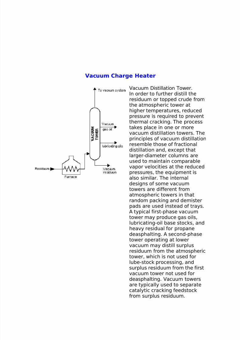
Vacuum Charge Heater
acuum Distillation Tower.In order to further distill theresiduum or topped crude fromthe atmospheric tower athigher temperatures% reducedpressure is re(uired to preventthermal crac ing. The processta es place in one or morevacuum distillation towers. Theprinciples of vacuum distillationresemble those of fractionaldistillation and% e'cept thatlarger"diameter columns areused to maintain comparablevapor velocities at the reducedpressures% the e(uipment is
also similar. The internaldesigns of some vacuumtowers are different fromatmospheric towers in thatrandom pac ing and demisterpads are used instead of trays./ typical first"phase vacuumtower may produce gas oils%lubricating"oil base stoc s% andheavy residual for propanedeasphalting. / second"phasetower operating at lowervacuum may distill surplusresiduum from the atmospherictower% which is not used forlube"stoc processing% andsurplus residuum from the firstvacuum tower not used fordeasphalting. acuum towersare typically used to separatecatalytic crac ing feedstoc
from surplus residuum.
8/16/2019 17730094 Fired Heaters
http://slidepdf.com/reader/full/17730094-fired-heaters 3/141
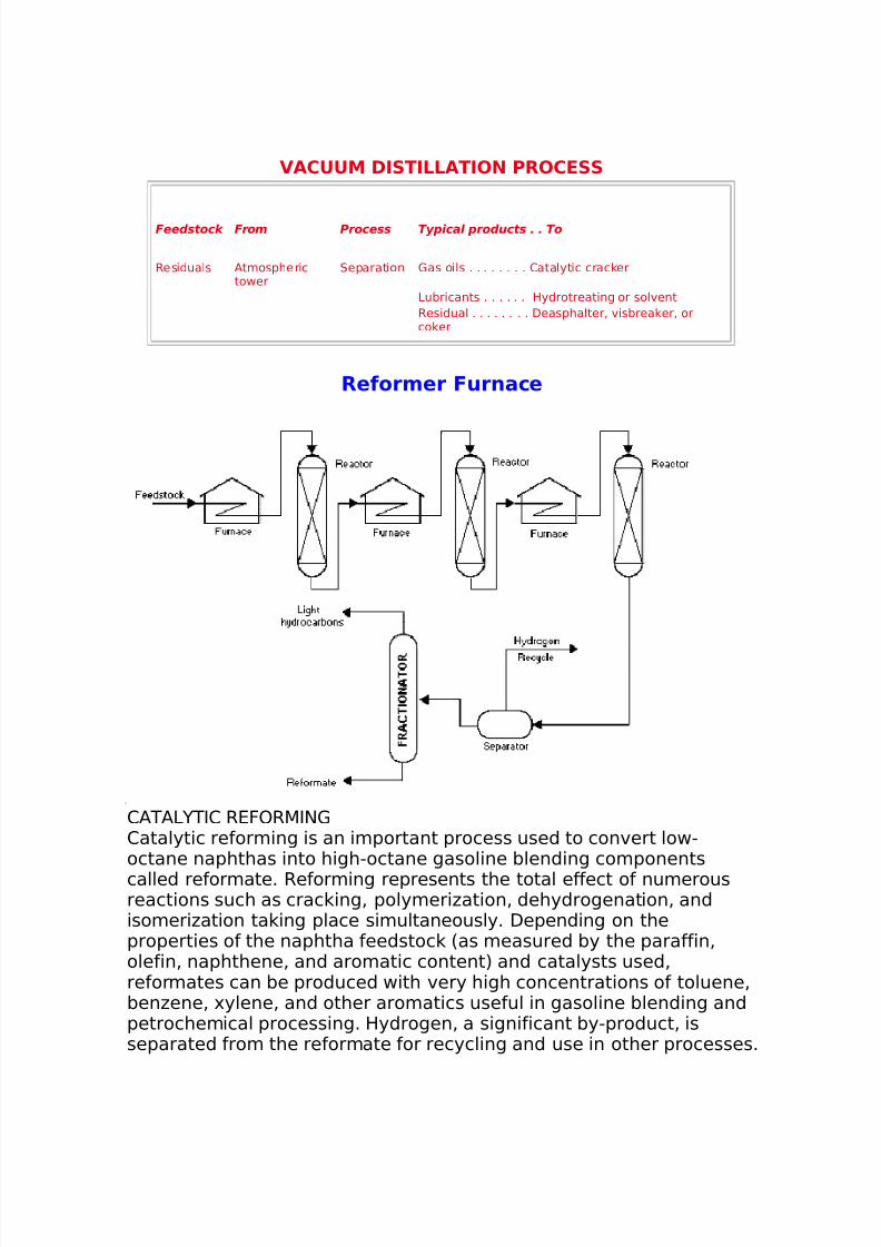
VACUUM DISTILLATION PROCESS
Feedstock From Process Typical products . . To
Residuals /tmospherictower
0eparation 1as oils . . . . . . . . 2atalytic crac er
3ubricants . . . . . . Hydrotreating or solventResidual . . . . . . . . Deasphalter% visbrea er% orco er
Reformer Furnace
2/T/3 TI2 R4F)R5I$12atalytic reforming is an important process used to convert low"octane naphthas into high"octane gasoline blending componentscalled reformate. Reforming represents the total effect of numerousreactions such as crac ing% polymeri#ation% dehydrogenation% andisomeri#ation ta ing place simultaneously. Depending on theproperties of the naphtha feedstoc 6as measured by the paraffin%olefin% naphthene% and aromatic content7 and catalysts used%reformates can be produced with very high concentrations of toluene%ben#ene% 'ylene% and other aromatics useful in gasoline blending andpetrochemical processing. Hydrogen% a significant by"product% isseparated from the reformate for recycling and use in other processes.
8/16/2019 17730094 Fired Heaters
http://slidepdf.com/reader/full/17730094-fired-heaters 4/141
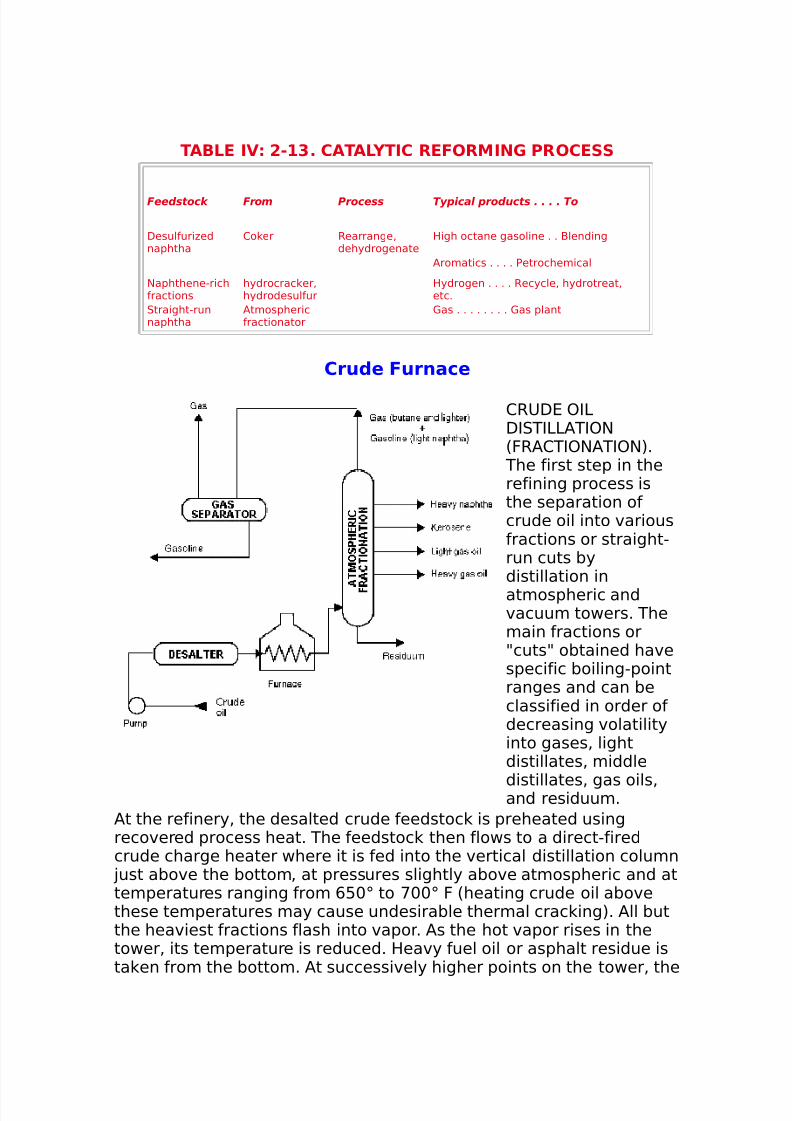
TABLE IV !"#$% CATAL&TIC REFORMIN' PROCESS
Feedstock From Process Typical products . . . . To
Desulfuri#ednaphtha
2o er Rearrange%dehydrogenate
High octane gasoline . . -lending
/romatics . . . . Petrochemical
$aphthene"richfractions
hydrocrac er%hydrodesulfur
Hydrogen . . . . Recycle% hydrotreat%etc.
0traight"runnaphtha
/tmosphericfractionator
1as . . . . . . . . 1as plant
Cru(e Furnace
2R8D4 )I3DI0TI33/TI)$6FR/2TI)$/TI)$7.
The first step in therefining process isthe separation ofcrude oil into variousfractions or straight"run cuts bydistillation inatmospheric andvacuum towers. Themain fractions or9cuts9 obtained havespecific boiling"pointranges and can beclassified in order ofdecreasing volatilityinto gases% lightdistillates% middle
distillates% gas oils%and residuum./t the refinery% the desalted crude feedstoc is preheated usingrecovered process heat. The feedstoc then flows to a direct"firedcrude charge heater where it is fed into the vertical distillation column
!ust above the bottom% at pressures slightly above atmospheric and attemperatures ranging from ,:+; to <++; F 6heating crude oil abovethese temperatures may cause undesirable thermal crac ing7. /ll butthe heaviest fractions flash into vapor. /s the hot vapor rises in thetower% its temperature is reduced. Heavy fuel oil or asphalt residue ista en from the bottom. /t successively higher points on the tower% the
8/16/2019 17730094 Fired Heaters
http://slidepdf.com/reader/full/17730094-fired-heaters 5/141
various ma!or products including lubricating oil% heating oil% erosene%gasoline% and uncondensed gases 6which condense at lowertemperatures7 are drawn off.
ATMOSPHERIC DISTILLATION PROCESS
Feedstock From Process Typical products . . . . . . To
2rude Desalting 0eparation 1ases . . . . . . . . . . . . . /tmospheric distillationtower
$aphtas. . . . . . . . . . . . Reforming or treating=erosene or distillates . . Treating1as oil . . . . . . . . . . . . . 2atalytic crac ingResidual . . . . . . . . . . . acuum tower or visbrea er
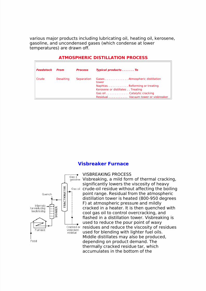
V)*+rea,er Furnace
I0-R4/=I$1 PR)2400isbrea ing% a mild form of thermal crac ing%
significantly lowers the viscosity of heavycrude"oil residue without affecting the boilingpoint range. Residual from the atmosphericdistillation tower is heated 6*++">:+ degrees
F7 at atmospheric pressure and mildlycrac ed in a heater. It is then (uenched withcool gas oil to control overcrac ing% andflashed in a distillation tower. isbrea ing isused to reduce the pour point of wa'yresidues and reduce the viscosity of residuesused for blending with lighter fuel oils.5iddle distillates may also be produced%depending on product demand. Thethermally crac ed residue tar% whichaccumulates in the bottom of the
8/16/2019 17730094 Fired Heaters
http://slidepdf.com/reader/full/17730094-fired-heaters 6/141
8/16/2019 17730094 Fired Heaters
http://slidepdf.com/reader/full/17730094-fired-heaters 7/141
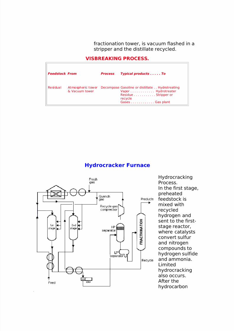
leaves the firststage% it is cooledand li(uefied andrun through ahydrocarbonseparator. Thehydrogen isrecycled to thefeedstoc . Theli(uid is chargedto a fractionator.Depending on theproducts desired
6gasolinecomponents% !etfuel% and gas oil7%the fractionator isrun to cut outsome portion ofthe first stagereactor out"turn.=erosene"rangematerial can beta en as aseparate side"draw product orincluded in thefractionatorbottoms with thegas oil.
The fractionator bottoms are again mi'ed with a hydrogen stream andcharged to the second stage. 0ince this material has already beensub!ected to some hydrogenation% crac ing% and reforming in the firststage% the operations of the second stage are more severe 6higher
temperatures and pressures7. 3i e the outturn of the first stage% thesecond stage product is separated from the hydrogen and charged tothe fractionator.
H&DROCRAC-IN' PROCESS%
8/16/2019 17730094 Fired Heaters
http://slidepdf.com/reader/full/17730094-fired-heaters 8/141
Feedstock From Process Typical products . . . . To
High pour point 2atalytic crac er%atmospheric& vacuum tower
Decomposition%hydrogenation
=erosen% !et fuel . . . .-lending
1as oil acuum tower% co er 1asoline% distillates . . -lending
Hydrogen Reformer Recycle% reformer gas . . 1asplant
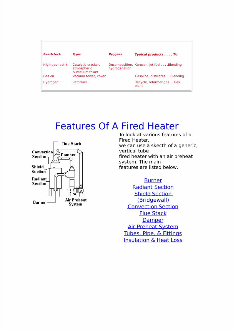
Features )f / Fired Heater To loo at various features of aFired Heater%we can use a s ecth of a generic%vertical tubefired heater with an air preheatsystem. The mainfeatures are listed below.
-urnerRadiant 0ection0hield 0ection
6-ridgewall72onvection 0ection
Flue 0tacDamper
/ir Preheat 0ystem Tubes% Pipe% & FittingsInsulation & Heat 3oss
8/16/2019 17730094 Fired Heaters
http://slidepdf.com/reader/full/17730094-fired-heaters 9/141
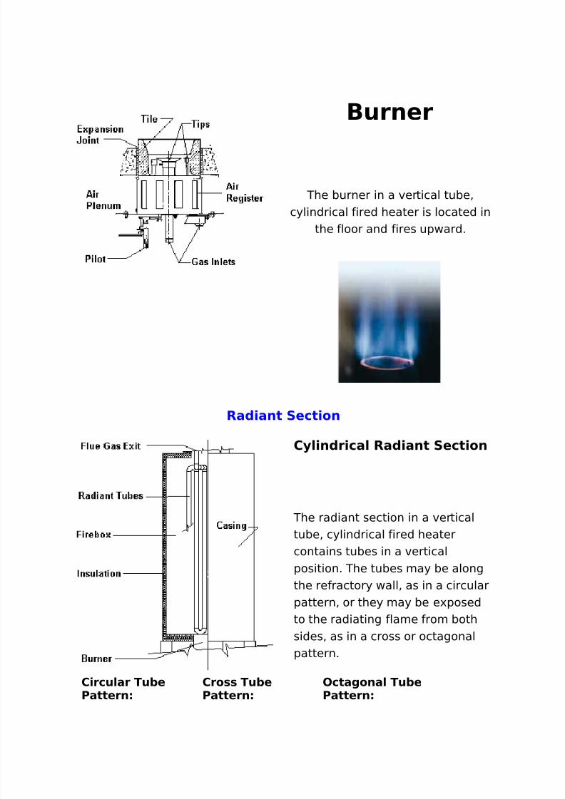
Burner
The burner in a vertical tube%cylindrical fired heater is located in
the floor and fires upward.
Ra()ant Sect)on
C./)n(r)ca/ Ra()ant Sect)on
The radiant section in a verticaltube% cylindrical fired heatercontains tubes in a verticalposition. The tubes may be alongthe refractory wall% as in a circularpattern% or they may be e'posedto the radiating flame from bothsides% as in a cross or octagonalpattern.
C)rcu/ar Tu+e
Pattern
Cro** Tu+e
Pattern
Octagona/ Tu+e
Pattern
8/16/2019 17730094 Fired Heaters
http://slidepdf.com/reader/full/17730094-fired-heaters 10/141
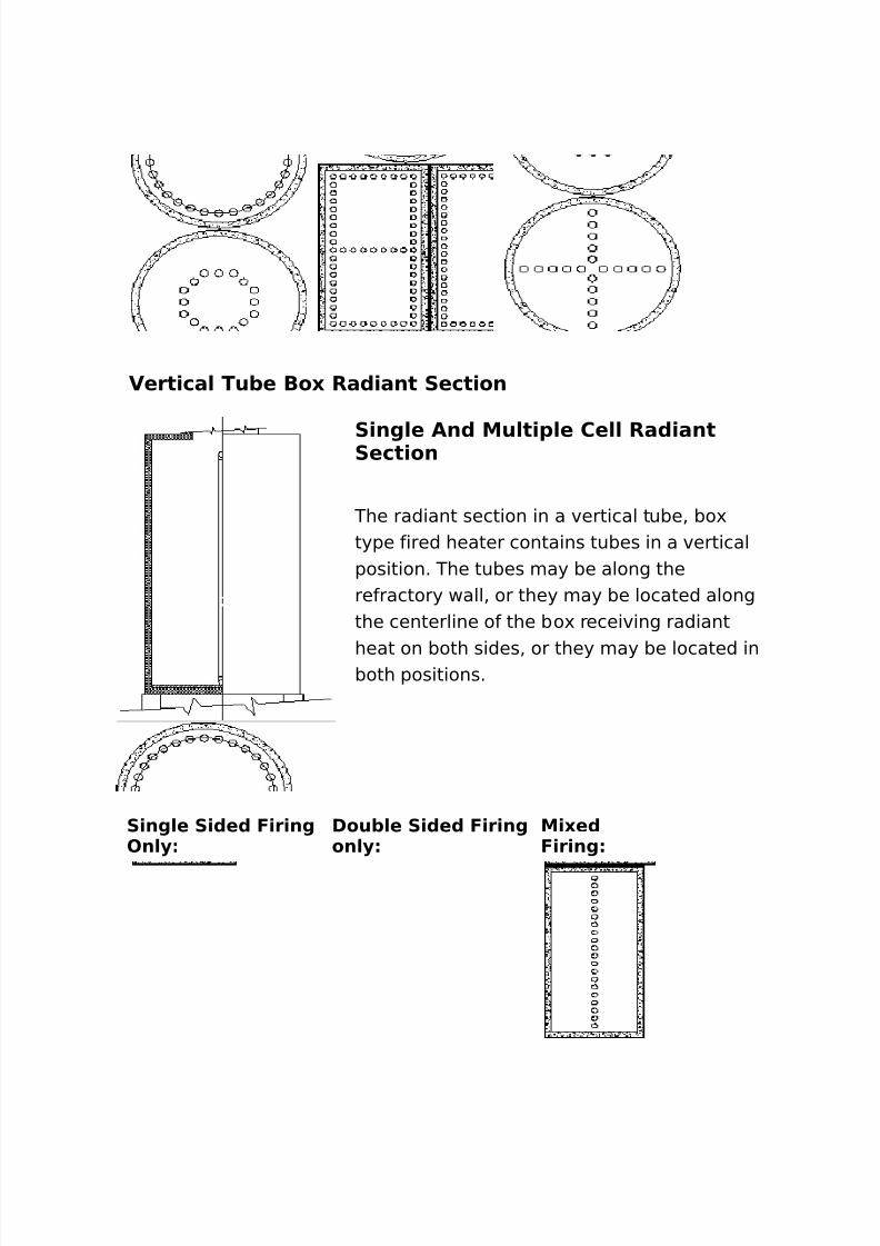
Vert)ca/ Tu+e Bo0 Ra()ant Sect)on
S)ng/e An( Mu/t)1/e Ce// Ra()antSect)on
The radiant section in a vertical tube% bo'type fired heater contains tubes in a verticalposition. The tubes may be along therefractory wall% or they may be located alongthe centerline of the bo' receiving radiant
heat on both sides% or they may be located inboth positions.
S)ng/e S)(e( F)r)ngOn/.
Dou+/e S)(e( F)r)ngon/.
M)0e(F)r)ng
8/16/2019 17730094 Fired Heaters
http://slidepdf.com/reader/full/17730094-fired-heaters 11/141
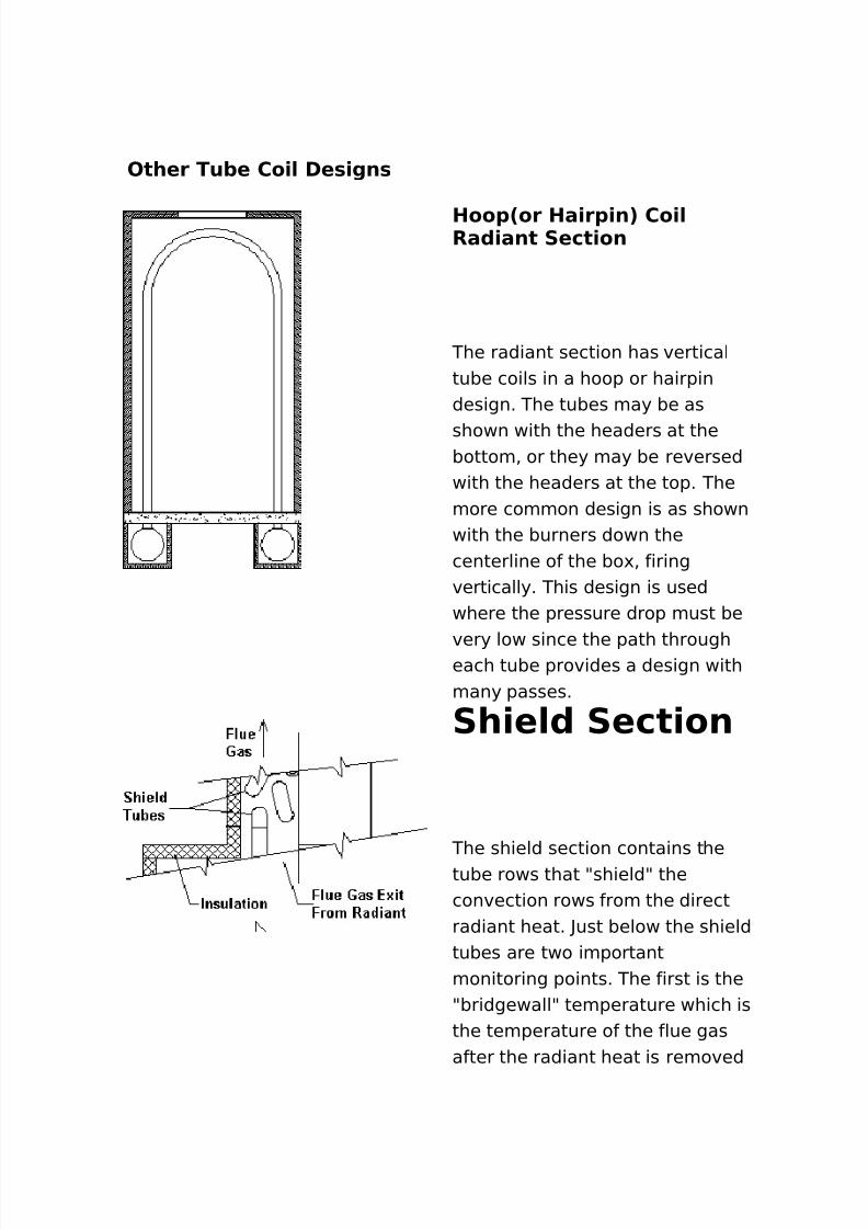
Other Tu+e Co)/ De*)gn*
Hoo12or Ha)r1)n3 Co)/Ra()ant Sect)on
The radiant section has verticaltube coils in a hoop or hairpindesign. The tubes may be as
shown with the headers at thebottom% or they may be reversedwith the headers at the top. Themore common design is as shownwith the burners down thecenterline of the bo'% firingvertically. This design is usedwhere the pressure drop must be
very low since the path througheach tube provides a design withmany passes.
Sh)e/( Sect)on
The shield section contains thetube rows that 9shield9 theconvection rows from the directradiant heat. ?ust below the shieldtubes are two importantmonitoring points. The first is the9bridgewall9 temperature which isthe temperature of the flue gasafter the radiant heat is removed
8/16/2019 17730094 Fired Heaters
http://slidepdf.com/reader/full/17730094-fired-heaters 12/141
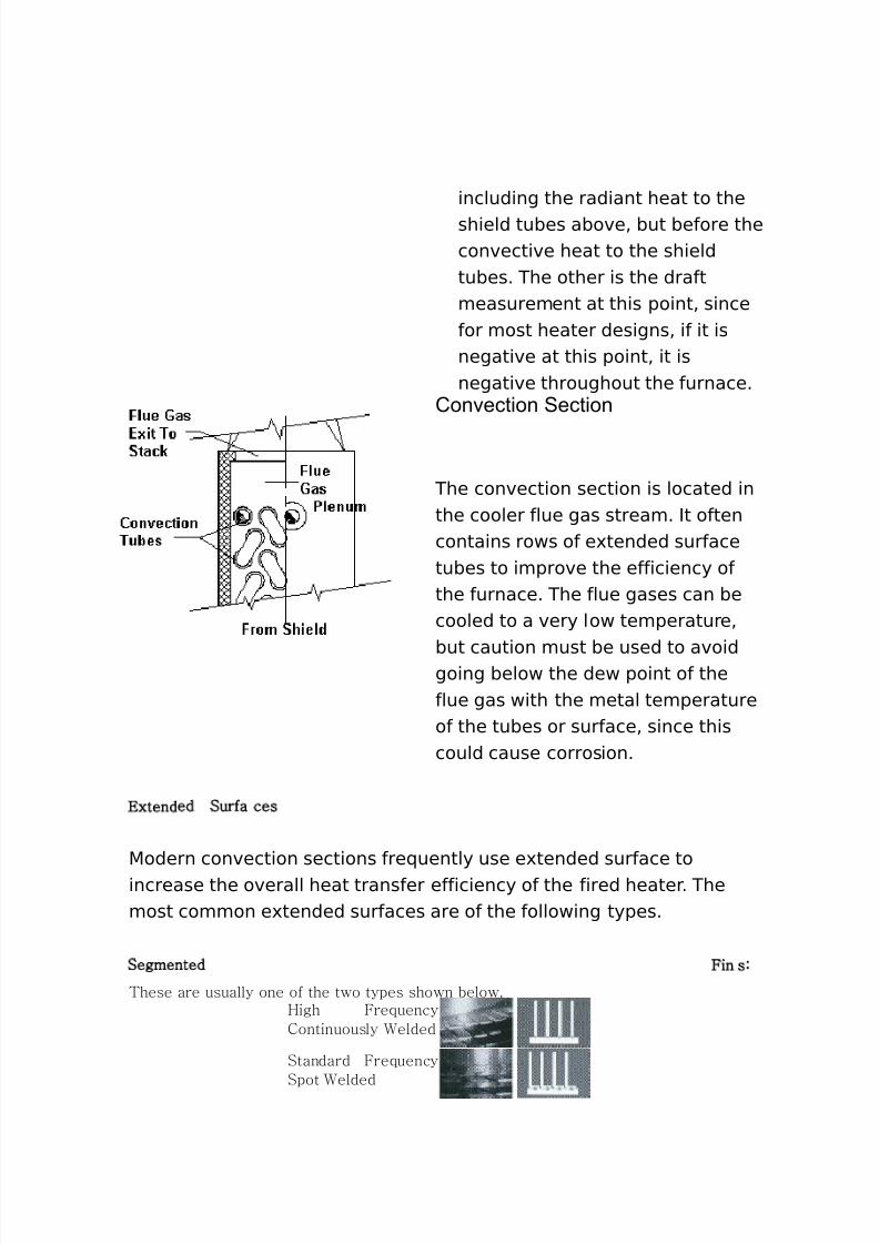
including the radiant heat to theshield tubes above% but before theconvective heat to the shieldtubes. The other is the draftmeasurement at this point% sincefor most heater designs% if it isnegative at this point% it isnegative throughout the furnace.
Convection Section
The convection section is located inthe cooler flue gas stream. It oftencontains rows of e'tended surfacetubes to improve the efficiency ofthe furnace. The flue gases can becooled to a very low temperature%
but caution must be used to avoidgoing below the dew point of theflue gas with the metal temperatureof the tubes or surface% since thiscould cause corrosion.
xtended Surfa ces
5odern convection sections fre(uently use e'tended surface toincrease the overall heat transfer efficiency of the fired heater. Themost common e'tended surfaces are of the following types.
Segmented Fin s:
These are usually one of the two types shown below.High FrequencyContinuously elded
Standard FrequencySpot elded
8/16/2019 17730094 Fired Heaters
http://slidepdf.com/reader/full/17730094-fired-heaters 13/141
The standard fre(uency% spot welded% design is not used in firedheaters very often since this design is normally selected when usingvery thin% high density finning such as in a large heat recovery boiler.5ost fired heater convections seldom use fins less than +.+@> inchthic . The standard fre(uency% spot welded fin also has a foot whichpresents a place where corrosion can occur if flue gases are corrosiveor moisture is present.
Sol id Fin s:
These are the most popular fins for modern fired heaters.High FrequencyContinuously elded
Stud Fin s:
These are used generally when the fuel is !o. " or higher.#esistance
elded
Thermal rating procedures for all these e'tended surface types are
presented in section @% Heat Transfer 2oncepts. -oth segmented fintypes are rated using the same formulas.
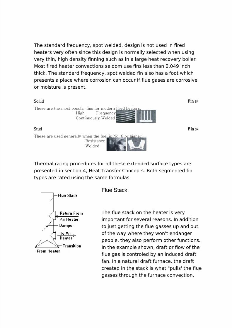
Flue Stack
The flue stac on the heater is veryimportant for several reasons. In additionto !ust getting the flue gasses up and outof the way where they wonAt endangerpeople% they also perform other functions.In the e'ample shown% draft or flow of theflue gas is controled by an induced draftfan. In a natural draft furnace% the draftcreated in the stac is what 9pullsA the fluegasses through the furnace convection.
8/16/2019 17730094 Fired Heaters
http://slidepdf.com/reader/full/17730094-fired-heaters 14/141
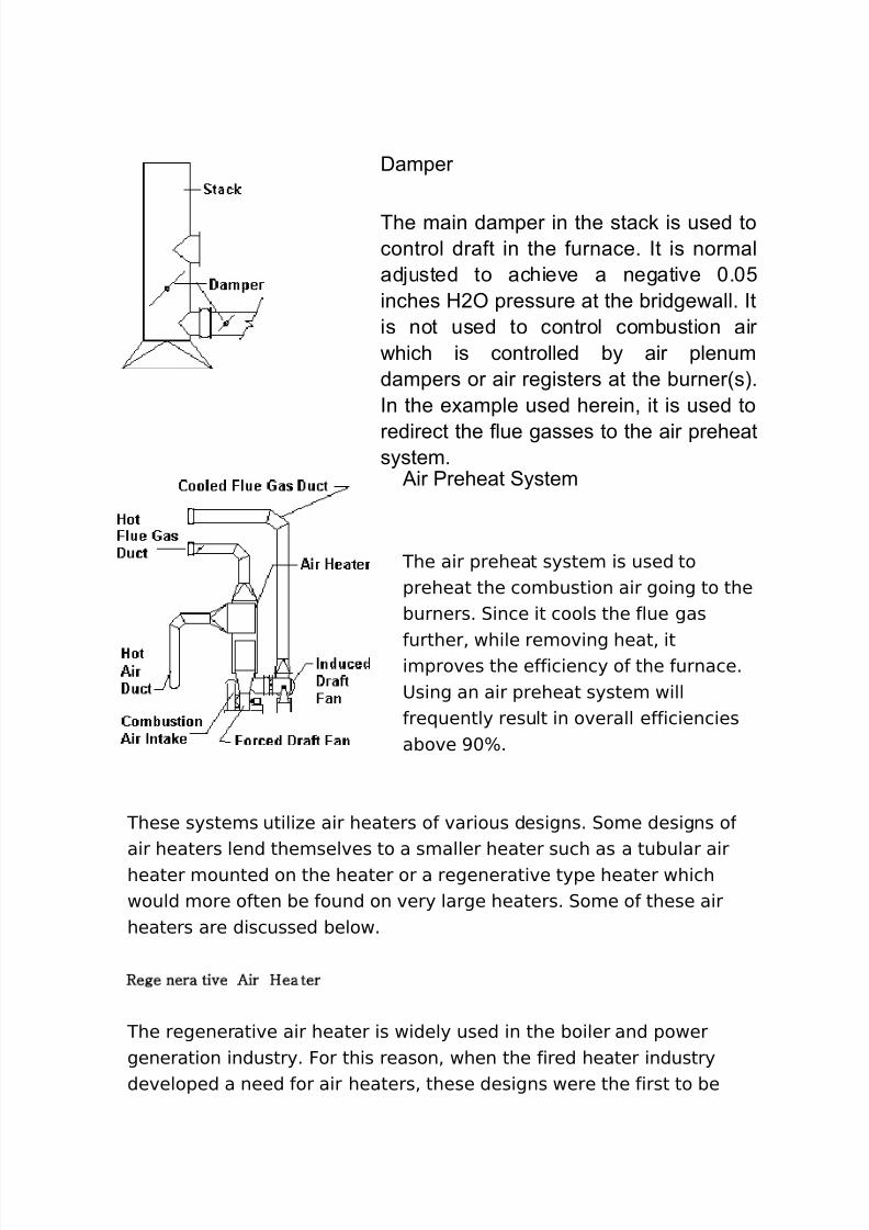
Damper
The main damper in the stack is used tocontrol draft in the furnace. It is normaladjusted to achieve a negative 0.05inches H ! pressure at the "ridge#all. Itis not used to control com"ustion air#hich is controlled "$ air plenumdampers or air registers at the "urner%s&.In the e'ample used herein( it is used to
redirect the flue gasses to the air preheats$stem.
)ir *reheat S$stem
The air preheat system is used topreheat the combustion air going to theburners. 0ince it cools the flue gas
further% while removing heat% itimproves the efficiency of the furnace.8sing an air preheat system willfre(uently result in overall efficienciesabove >+B.
These systems utili#e air heaters of various designs. 0ome designs ofair heaters lend themselves to a smaller heater such as a tubular airheater mounted on the heater or a regenerative type heater whichwould more often be found on very large heaters. 0ome of these airheaters are discussed below.
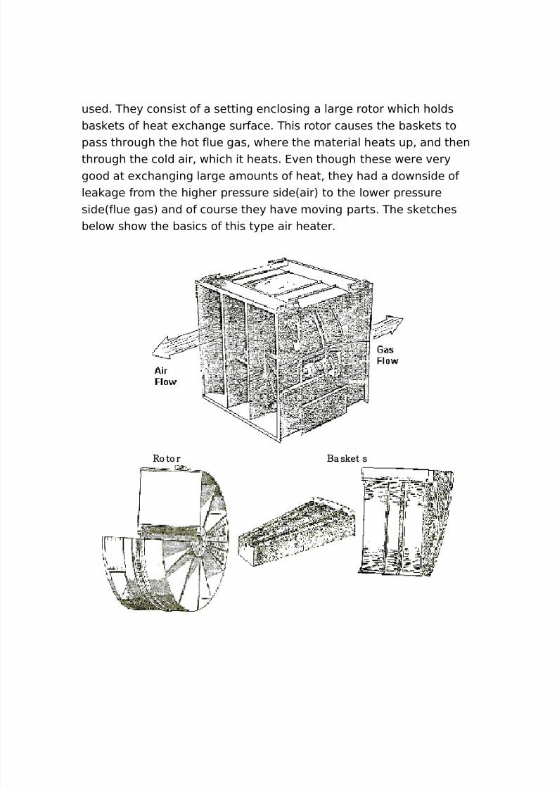
#ege nera ti$e %ir Hea ter
The regenerative air heater is widely used in the boiler and powergeneration industry. For this reason% when the fired heater industrydeveloped a need for air heaters% these designs were the first to be
8/16/2019 17730094 Fired Heaters
http://slidepdf.com/reader/full/17730094-fired-heaters 15/141
used. They consist of a setting enclosing a large rotor which holdsbas ets of heat e'change surface. This rotor causes the bas ets topass through the hot flue gas% where the material heats up% and thenthrough the cold air% which it heats. 4ven though these were verygood at e'changing large amounts of heat% they had a downside oflea age from the higher pressure side6air7 to the lower pressureside6flue gas7 and of course they have moving parts. The s etchesbelow show the basics of this type air heater.
#o to r &a s'et s
8/16/2019 17730094 Fired Heaters
http://slidepdf.com/reader/full/17730094-fired-heaters 16/141
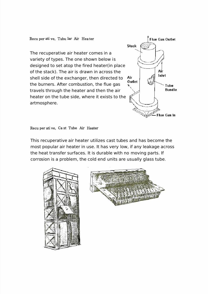
#ecu per ati $e( Tubu lar %ir Hea ter
The recuperative air heater comes in avariety of types. The one shown below isdesigned to set atop the fired heater6in placeof the stac 7. The air is drawn in across theshell side of the e'changer% then directed tothe burners. /fter combustion% the flue gastravels through the heater and then the airheater on the tube side% where it e'ists to the
artmosphere.
#ecu per ati $e( Ca st Tube %ir Heater
This recuperative air heater utili#es cast tubes and has become themost popular air heater in use. It has very low% if any lea age across
the heat transfer surfaces. It is durable with no moving parts. Ifcorrosion is a problem% the cold end units are usually glass tube.
8/16/2019 17730094 Fired Heaters
http://slidepdf.com/reader/full/17730094-fired-heaters 17/141
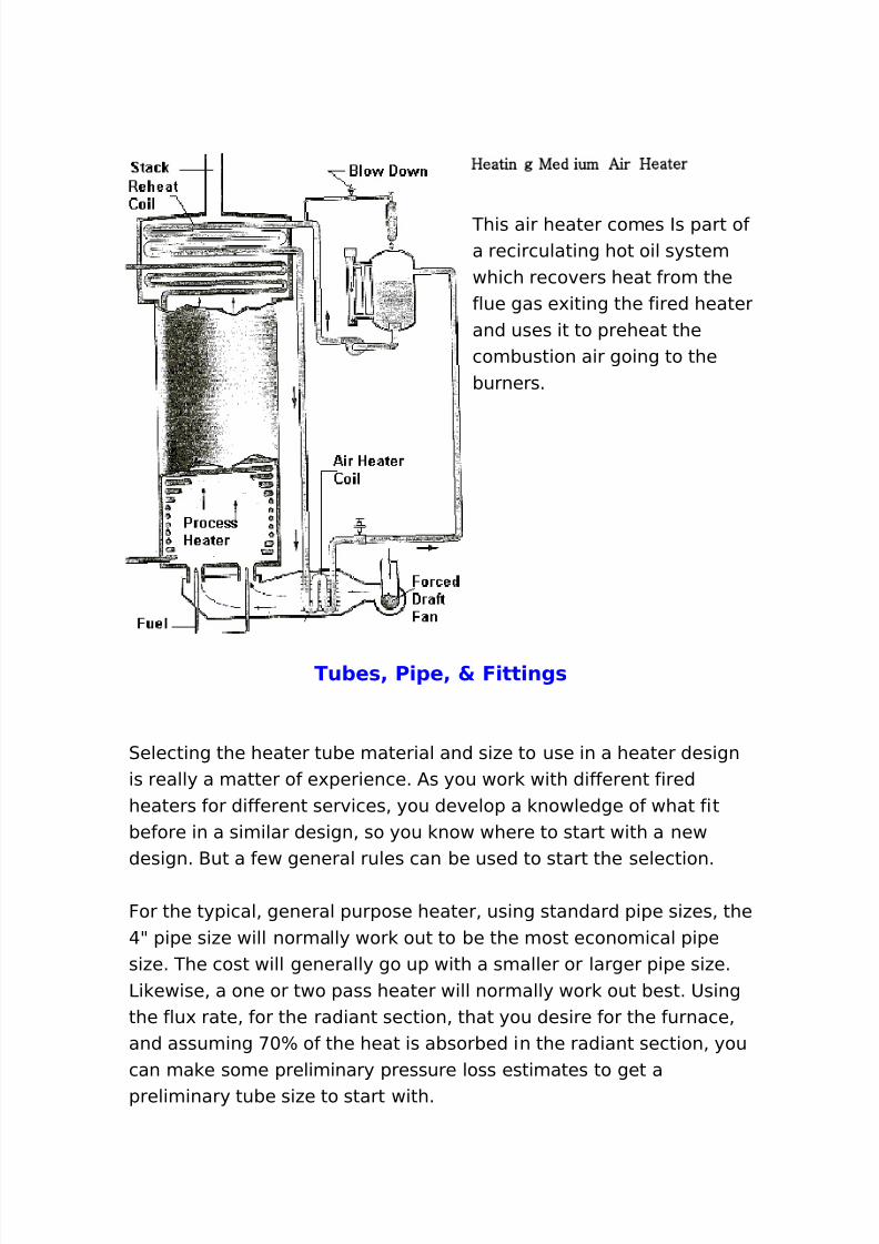
Heatin g )ed ium %ir Heater
This air heater comes Is part ofa recirculating hot oil systemwhich recovers heat from theflue gas e'iting the fired heaterand uses it to preheat thecombustion air going to theburners.
Tu+e*4 P)1e4 5 F)tt)ng*
0electing the heater tube material and si#e to use in a heater designis really a matter of e'perience. /s you wor with different firedheaters for different services% you develop a nowledge of what fitbefore in a similar design% so you now where to start with a newdesign. -ut a few general rules can be used to start the selection.
For the typical% general purpose heater% using standard pipe si#es% the@9 pipe si#e will normally wor out to be the most economical pipesi#e. The cost will generally go up with a smaller or larger pipe si#e.3i ewise% a one or two pass heater will normally wor out best. 8singthe flu' rate% for the radiant section% that you desire for the furnace%and assuming <+B of the heat is absorbed in the radiant section% youcan ma e some preliminary pressure loss estimates to get apreliminary tube si#e to start with.
8/16/2019 17730094 Fired Heaters
http://slidepdf.com/reader/full/17730094-fired-heaters 18/141
In a similar manner% you can ma e some preliminary estimates todetermine what the design metal temperature for the heater tubesneed to be. Cith this temperature% you would select the least materialthat is good for the temperature. 4ventual analysis may show that ahigher alloy and a thinner wall may be more economical% so runningcalculations with several materials is always wise.
T.1)ca/ gener)c4 1)1e4 an( tu+e *1ec)f)cat)on* u*e( for heatertu+e*
1eneric0pecification
Pipe0pecification
Tube0pecification
2arbon 0teel / +, 1r - / <* /E 2r 5o / GG: 1r P / G TE 2r 5o / GG: 1r P / G T
: 2r 5o / GG: 1r P: / G T:> 2r 5o / GG: 1r P> / G T>
* 2r * $i / G TP G+@ / G TP G+@, 2r $i 5o / G TP G , / G TP G ,* 2r + $i Ti / G TP G / G TP G* 2r + $i Ti / G TP G H / G TP G H
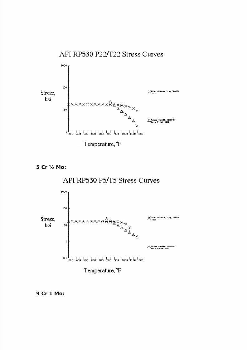
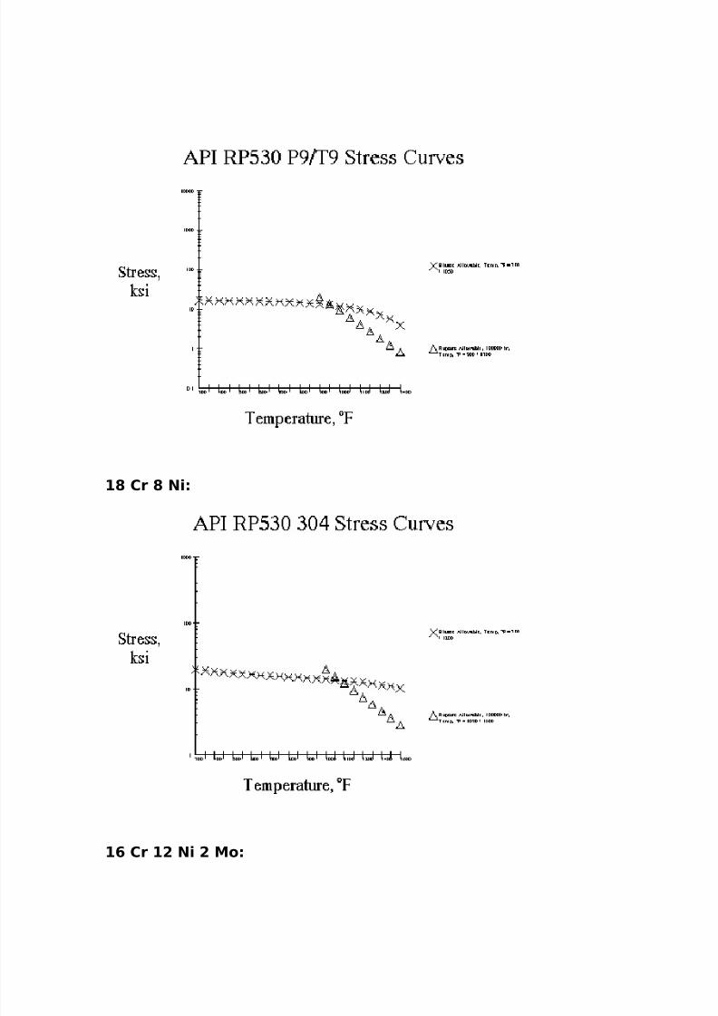
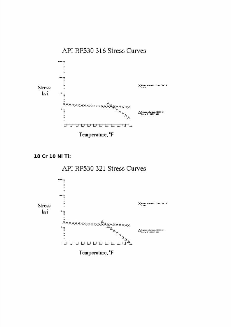
/nd other% more e'otic materials for special furnaces are used as maybe needed. The wall thic ness re(uired is normally calculated byusing the /PI RP:G+ recommended practice% with the ruptureallowable stress for ++%+++ hours design life or the elastic allowablestress being used depending on the design tube wall temperature.
Tu+e 6a// Th)c,ne**For 4lastic Design 6lower temperatures7
t * 7 2P e 8 D o 3 9 2! 8 S e : P e 3
/nd%t m 7 t * : CA
For Rupture Design 6higher temperatures7t * 7 2P r 8 D o 3 9 2! 8 S r : P r3
8/16/2019 17730094 Fired Heaters
http://slidepdf.com/reader/full/17730094-fired-heaters 19/141
/nd%
t m 7 t * : F8CA
Chere%t s 0tress thic ness% inPe 4lastic design pressure% psigP r Rupture design pressure% psigDo )utside tube diameter% in0 e 4lastic allowable stress at design temperature%psi
0 r Rupture allowable stress at designtemperature% psit m 5inimum thic ness including corrosion% in2/ 2orrosion allowance% inF 2orrosion fraction as a function of - and nChere%- 2/Jt s
n rupture e'ponent at design temperature
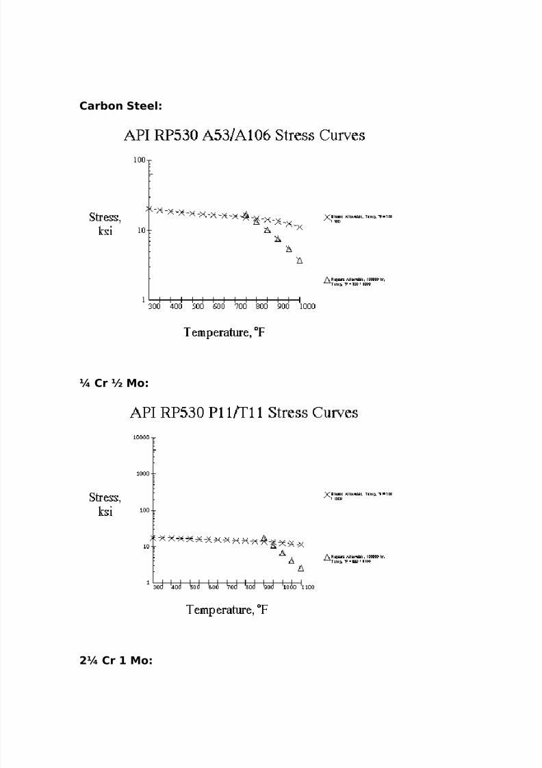
The tube metal temperature can be calculated as described in 9Heat Transfer9 section% under 9Tube Call Temperature 2alculation9 in thismaterial. From this temperature% we can select the stress values fromthe following curves.
8/16/2019 17730094 Fired Heaters
http://slidepdf.com/reader/full/17730094-fired-heaters 20/141
Car+on Stee/
; Cr < Mo
!; Cr # Mo
8/16/2019 17730094 Fired Heaters
http://slidepdf.com/reader/full/17730094-fired-heaters 21/141
= Cr < Mo
> Cr # Mo
8/16/2019 17730094 Fired Heaters
http://slidepdf.com/reader/full/17730094-fired-heaters 22/141
#? Cr ? N)
#@ Cr #! N) ! Mo
8/16/2019 17730094 Fired Heaters
http://slidepdf.com/reader/full/17730094-fired-heaters 23/141
#? Cr # N) T)
8/16/2019 17730094 Fired Heaters
http://slidepdf.com/reader/full/17730094-fired-heaters 24/141
#? Cr # N) T)
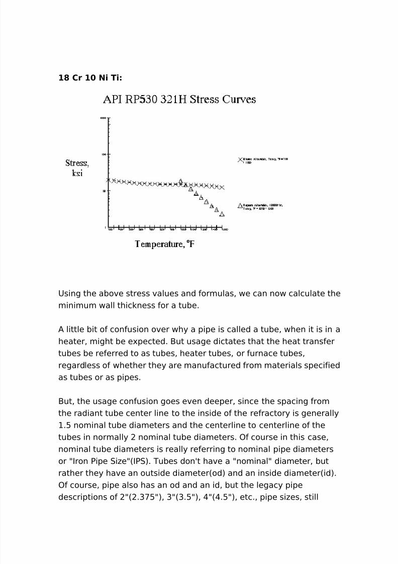
8sing the above stress values and formulas% we can now calculate theminimum wall thic ness for a tube.
/ little bit of confusion over why a pipe is called a tube% when it is in aheater% might be e'pected. -ut usage dictates that the heat transfertubes be referred to as tubes% heater tubes% or furnace tubes%regardless of whether they are manufactured from materials specifiedas tubes or as pipes.
-ut% the usage confusion goes even deeper% since the spacing fromthe radiant tube center line to the inside of the refractory is generally
.: nominal tube diameters and the centerline to centerline of thetubes in normally nominal tube diameters. )f course in this case%nominal tube diameters is really referring to nominal pipe diametersor 9Iron Pipe 0i#e96IP07. Tubes donAt have a 9nominal9 diameter% butrather they have an outside diameter6od7 and an inside diameter6id7.)f course% pipe also has an od and an id% but the legacy pipedescriptions of 96 .G<:97% G96G.:97% @96@.:97% etc.% pipe si#es% still
8/16/2019 17730094 Fired Heaters
http://slidepdf.com/reader/full/17730094-fired-heaters 25/141
persist to this day. /s well% the designation of pipe schedules such as@+% ,+% *+% etc. are still in common use today. Therefore% many 80programs still cater to this usage by including built in routines toconvert these designations to od% id% and wall thic ness which mustbe used in the formulas.
0o even if you are designing a furnace in 4urope% and you are using,., : inch od tubes% you would most li ely still set the tube centerlineto wall dimension to .: IP06or nominal diameters7% or .: K , >inches. 3i ewise you would probably set the centerline to centerline
tube spacing at two times the IP06or nominal diameter7% K , inches. This also might be because the rolling e(uipment for thereturn bends e'ist for these 9standard9 *+; returns% or the tubesupport casting patterns may e'ist for this standoff. /ll of theseconstraints need to be considered when setting the dimensions of thefurnace during the design.
Chen using tubes with the )D of a standard pipe si#e or using piping
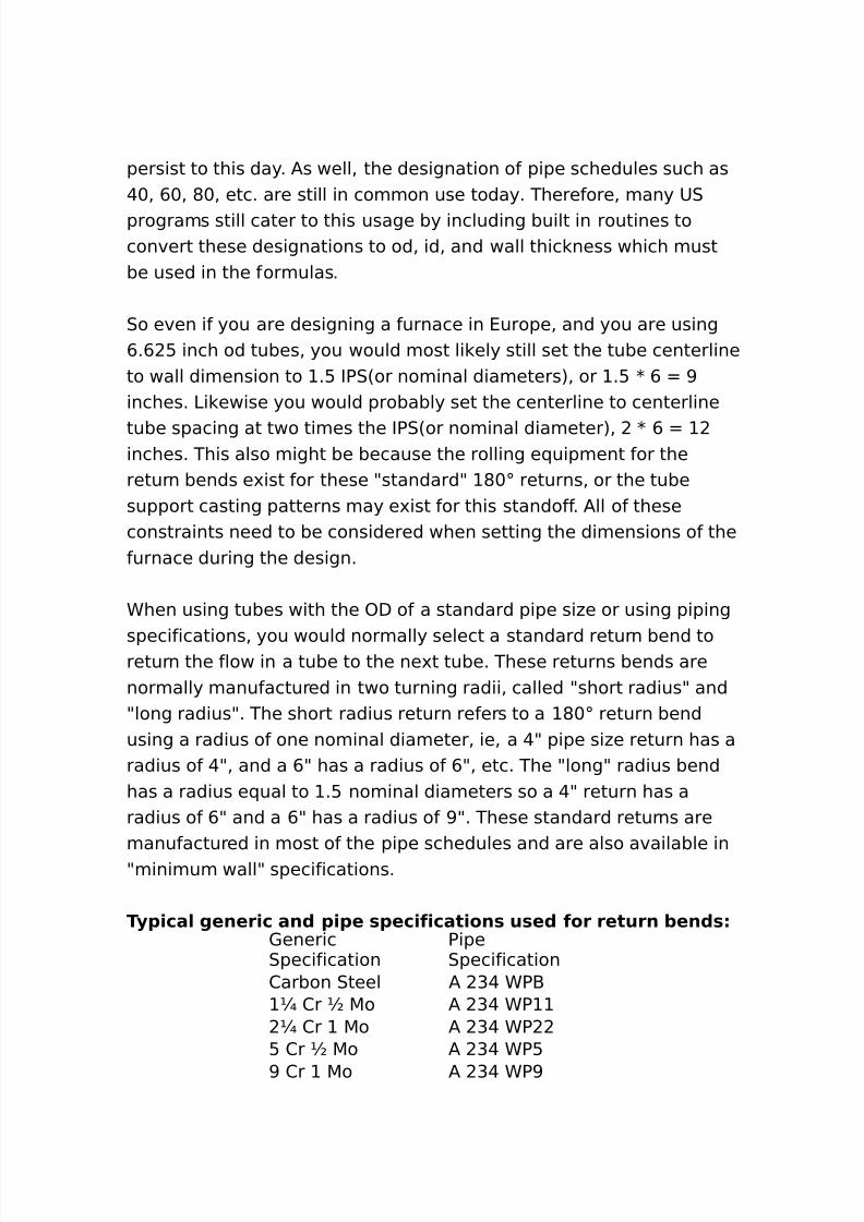
specifications% you would normally select a standard return bend toreturn the flow in a tube to the ne't tube. These returns bends arenormally manufactured in two turning radii% called 9short radius9 and9long radius9. The short radius return refers to a *+; return bendusing a radius of one nominal diameter% ie% a @9 pipe si#e return has aradius of @9% and a ,9 has a radius of ,9% etc. The 9long9 radius bendhas a radius e(ual to .: nominal diameters so a @9 return has aradius of ,9 and a ,9 has a radius of >9. These standard returns aremanufactured in most of the pipe schedules and are also available in9minimum wall9 specifications.
T.1)ca/ gener)c an( 1)1e *1ec)f)cat)on* u*e( for return +en(* 1eneric0pecification
Pipe0pecification
2arbon 0teel / G@ CP-E 2r 5o / G@ CPE 2r 5o / G@ CP
: 2r 5o / G@ CP:
> 2r 5o / G@ CP>
8/16/2019 17730094 Fired Heaters
http://slidepdf.com/reader/full/17730094-fired-heaters 26/141
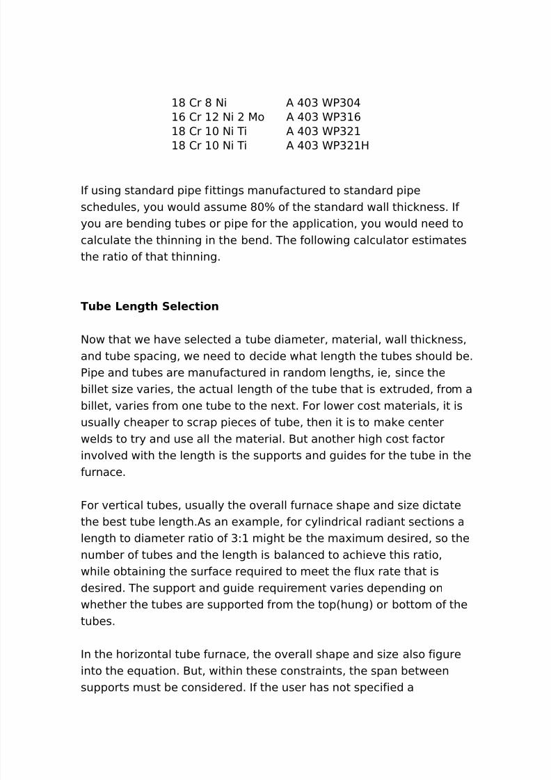
* 2r * $i / @+G CPG+@, 2r $i 5o / @+G CPG ,
* 2r + $i Ti / @+G CPG* 2r + $i Ti / @+G CPG H
If using standard pipe fittings manufactured to standard pipeschedules% you would assume *+B of the standard wall thic ness. Ifyou are bending tubes or pipe for the application% you would need tocalculate the thinning in the bend. The following calculator estimatesthe ratio of that thinning.
Tu+e Length Se/ect)on
$ow that we have selected a tube diameter% material% wall thic ness%and tube spacing% we need to decide what length the tubes should be.Pipe and tubes are manufactured in random lengths% ie% since thebillet si#e varies% the actual length of the tube that is e'truded% from a
billet% varies from one tube to the ne't. For lower cost materials% it isusually cheaper to scrap pieces of tube% then it is to ma e centerwelds to try and use all the material. -ut another high cost factorinvolved with the length is the supports and guides for the tube in thefurnace.
For vertical tubes% usually the overall furnace shape and si#e dictatethe best tube length./s an e'ample% for cylindrical radiant sections alength to diameter ratio of GL might be the ma'imum desired% so thenumber of tubes and the length is balanced to achieve this ratio%while obtaining the surface re(uired to meet the flu' rate that isdesired. The support and guide re(uirement varies depending onwhether the tubes are supported from the top6hung7 or bottom of thetubes.
In the hori#ontal tube furnace% the overall shape and si#e also figureinto the e(uation. -ut% within these constraints% the span betweensupports must be considered. If the user has not specified a
8/16/2019 17730094 Fired Heaters
http://slidepdf.com/reader/full/17730094-fired-heaters 27/141
ma'imum span% then generally you would not want to e'ceed G: tube)DAs. This has been a general industry 9not to e'ceed9 rule of thumbused for many furnace designs. -ut care should be ta en to considerthe service and wall temperature of the tubes. )nce you havedetermined the span between supports% the tube length would beselected to use the minimum number of supports% while avoidingunnecessary centerwelds% if centerwelds are allowed by user. /ll ofthis must be balanced with the fact that the pressure loss in the tubesis increased dramatically in the returns% so generally you want thelongest straight tube possible. The pressure loss in the returns is
reviewed in the 9Process9 section % under 9Intube Pressure Drop9.
In*u/at)on 5 Heat Lo**
The insulation in a furnace is e'tremely important for a number ofreasons. The insulation provides a means of eeping the heatcontained in the heater where it can be absorbed by the heater tubes%
resulting in higher overall efficiencies. The insulation also eeps thee'ternal shell cooler ma ing it safe for operating and maintenancepersonnel to safely wor around the furnace. This cooler casingtemperature also results in the structural stability of the overallstructure.
Twenty years ago% most of the insulation used in fired heaters was thegunned or cast refractory. This material often% was mi'ed on site atthe heater manufacturerAs shop% and thus fre(uently varied ininsulating properties. The more popularly used mi'es li e L L@ 3Hand others became standard and over time the insulating propertiesbecame very predictable. This was improved upon by the offering ofproprietary mi'es% by a number of companies% which were pac agedin controlled environments and were thus more predictable in theirapplication.
During the early eighties% ceramic fibers became accepted in theheater industry and since they are a much better insulator% they
8/16/2019 17730094 Fired Heaters
http://slidepdf.com/reader/full/17730094-fired-heaters 28/141
(uic ly caused a decline in the use of refractory. In general% G inchesof ceramic fiber blan et could do a better !ob than , inches ofrefractory and weighed much less. /s an e'ample% if we have a hotface temperature of ++ ;F and an air temperature of <+ ;F on avertical wall with no wind blowing% ,9 L L@ 3H gunned has a coldface temperature of +:.: ;F where G9 *M G++;F ceramic fiber wouldhave a cold face temperature of , . ;F. /nd this is with a weightless than +B of the gunned refractory% which reduces freight cost.Furthermore% the ceramic fiber blan et does not re(uire 9drying9 inthe field as would be re(uired with the refractory.
Refractory is still used in special furnaces and in areas where it ismore durable or easier to install. The floor of a furnace which must bewal ed on during maintenance and inspection% may use castablerefractory or bric % or both because it is more durable. 4nd tubesheets% when they have multiple tube penetrations such as in an endsupported tube convection may utili#e gunned refractory because it iseasier6less costly7 to apply between the openings for the tubes then
ceramic fiber blan et.
Heat Lo** Through In*u/at)on
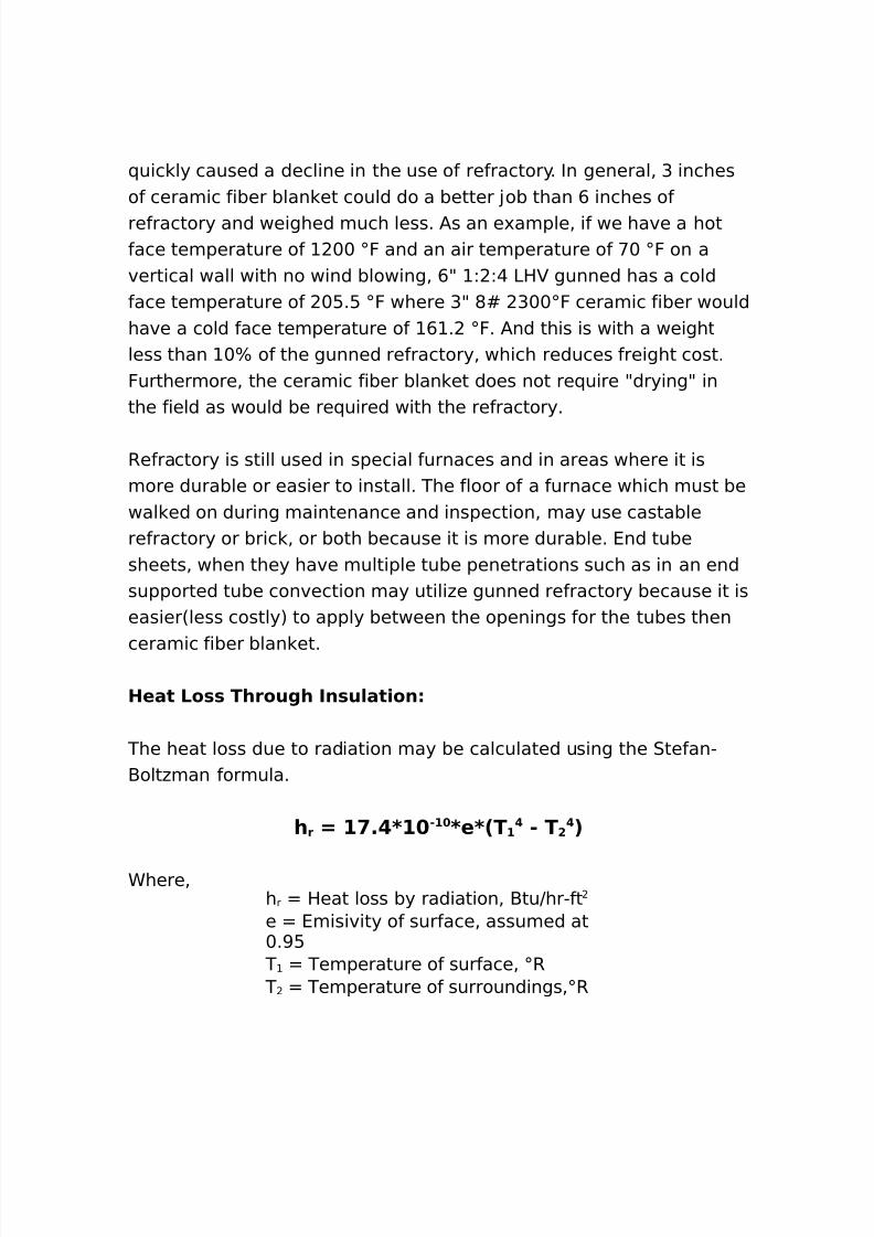
The heat loss due to radiation may be calculated using the 0tefan"-olt#man formula.
h r 7 # % 8# "# 8e82T # " T ! 3
Chere%h r Heat loss by radiation% -tuJhr"fte 4misivity of surface% assumed at+.>:
T Temperature of surface% ;R T Temperature of surroundings%;R
8/16/2019 17730094 Fired Heaters
http://slidepdf.com/reader/full/17730094-fired-heaters 29/141
The heat loss due to free convection may be calculated using thefollowing method.
h c 7 %=$8C82#9T a g 3 %#?82T # " T ! 3#%!
Chere%h c Heat loss by convection% -tuJhr"ft2 / constant% assumed at L
.<> for an arch or roof
.G> for a wall+.> for a floor
T avg /verage temperature of wall andsurroundings%;R
The heat loss due to forced convection% where the air velocity isgreater than #ero% may be calculated using the following method.
h fc 7 2# : %!!= 8 V382T # " T ! 3
Chere%h fc Heat loss by forced convection% -tuJhr"ft
elocity of air across surface% ftJsec
To visuali#e the differences in the various materials% used forinsulation% the following calculator can be used to run calculations forsome of these materials under different conditions.
2onfigurations )f Fired Heaters
8/16/2019 17730094 Fired Heaters
http://slidepdf.com/reader/full/17730094-fired-heaters 30/141
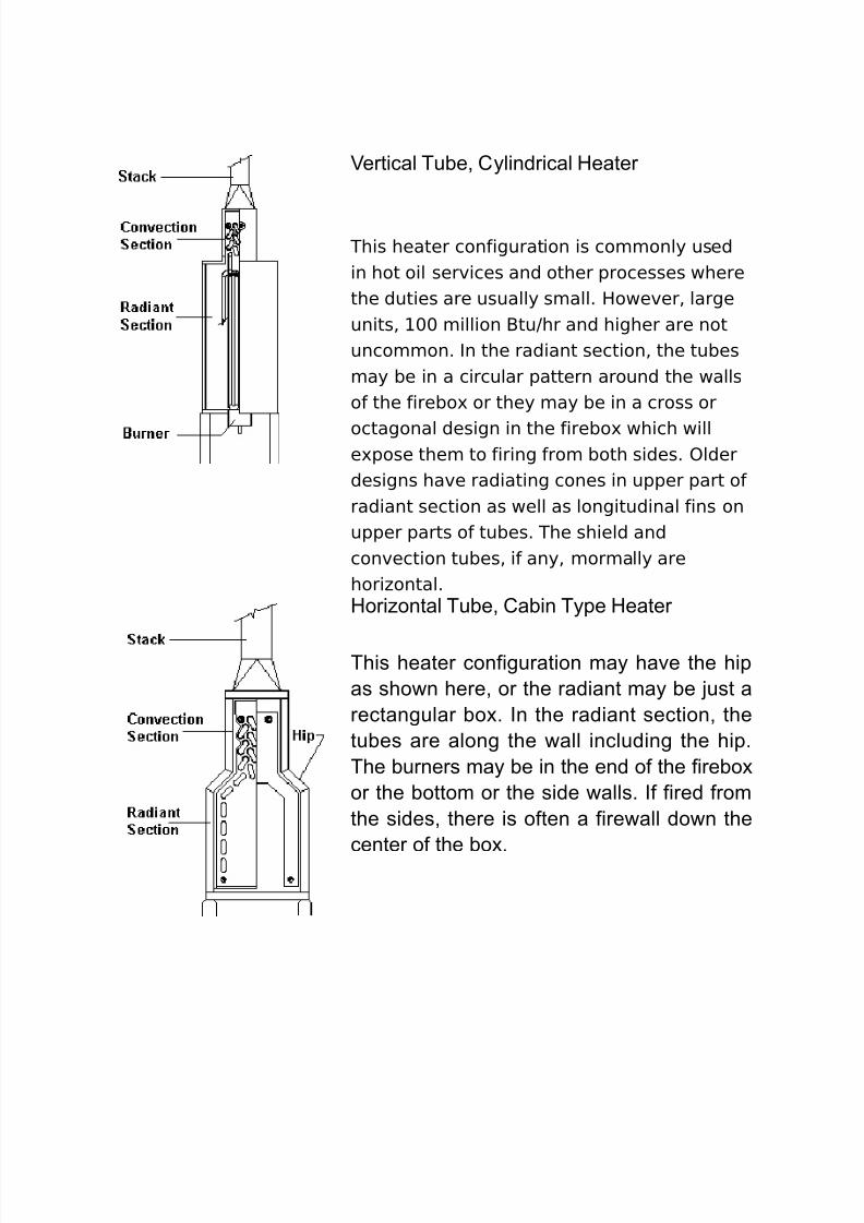
+ertical Tu"e( C$lindrical Heater
This heater configuration is commonly usedin hot oil services and other processes wherethe duties are usually small. However% largeunits% ++ million -tuJhr and higher are notuncommon. In the radiant section% the tubesmay be in a circular pattern around the wallsof the firebo' or they may be in a cross or
octagonal design in the firebo' which wille'pose them to firing from both sides. )lderdesigns have radiating cones in upper part ofradiant section as well as longitudinal fins onupper parts of tubes. The shield andconvection tubes% if any% mormally arehori#ontal.Hori,ontal Tu"e( Ca"in T$pe Heater
This heater configuration ma$ have the hipas sho#n here( or the radiant ma$ "e just arectangular "o'. In the radiant section( thetu"es are along the #all including the hip.The "urners ma$ "e in the end of the fire"o'or the "ottom or the side #alls. If fired fromthe sides( there is often a fire#all do#n thecenter of the "o'.
8/16/2019 17730094 Fired Heaters
http://slidepdf.com/reader/full/17730094-fired-heaters 31/141
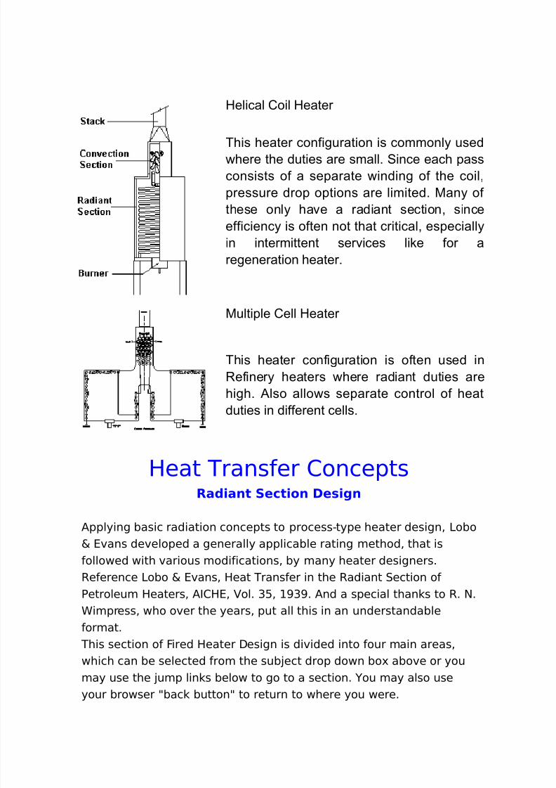
Helical Coil Heater
This heater configuration is commonl$ used#here the duties are small. Since each passconsists of a separate #inding of the coil(pressure drop options are limited. -an$ ofthese onl$ have a radiant section( sinceefficienc$ is often not that critical( especiall$in intermittent services like for aregeneration heater.
-ultiple Cell Heater
This heater configuration is often used inefiner$ heaters #here radiant duties are
high. )lso allo#s separate control of heat
duties in different cells.
Heat Transfer 2onceptsRa()ant Sect)on De*)gn
/pplying basic radiation concepts to process"type heater design% 3obo& 4vans developed a generally applicable rating method% that isfollowed with various modifications% by many heater designers.Reference 3obo & 4vans% Heat Transfer in the Radiant 0ection ofPetroleum Heaters% /I2H4% ol. G:% >G>. /nd a special than s to R. $.Cimpress% who over the years% put all this in an understandableformat.
This section of Fired Heater Design is divided into four main areas%which can be selected from the sub!ect drop down bo' above or youmay use the !ump lin s below to go to a section. ou may also useyour browser 9bac button9 to return to where you were.
8/16/2019 17730094 Fired Heaters
http://slidepdf.com/reader/full/17730094-fired-heaters 32/141
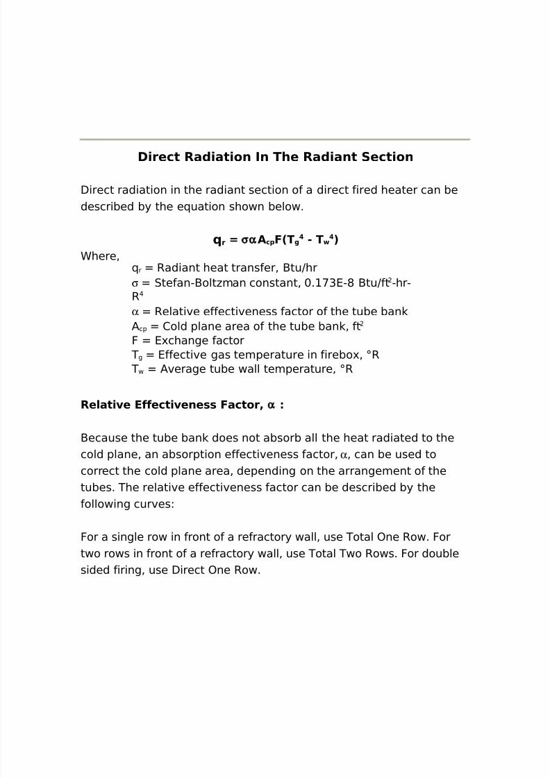
D)rect Ra()at)on In The Ra()ant Sect)on
Direct radiation in the radiant section of a direct fired heater can bedescribed by the e(uation shown below.
r 7 σα Ac1 F2T g " T 3Chere%
( r Radiant heat transfer% -tuJhrσ 0tefan"-olt#man constant% +. <G4"* -tuJft "hr"R@
α Relative effectiveness factor of the tube ban/ cp 2old plane area of the tube ban % ftF 4'change factor
T g 4ffective gas temperature in firebo'% ;R T w /verage tube wall temperature% ;R
Re/at) e Effect) ene** Factor4 α
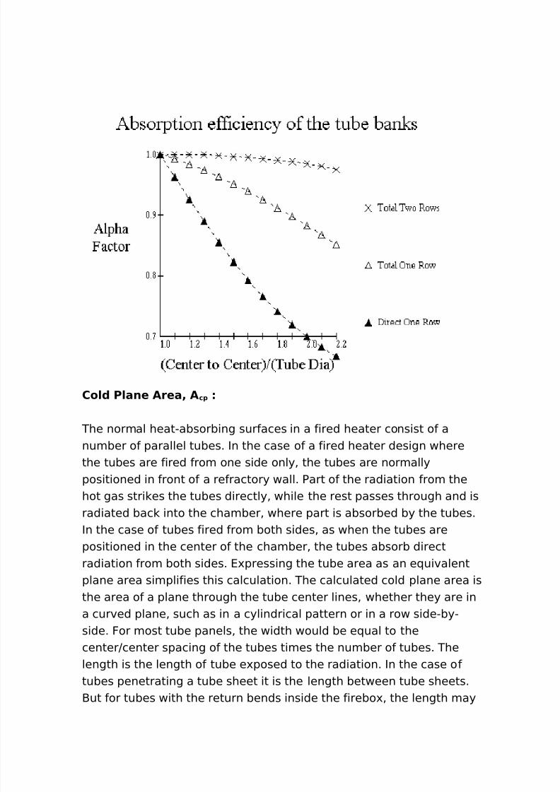
-ecause the tube ban does not absorb all the heat radiated to thecold plane% an absorption effectiveness factor% α % can be used tocorrect the cold plane area% depending on the arrangement of thetubes. The relative effectiveness factor can be described by thefollowing curvesL
For a single row in front of a refractory wall% use Total )ne Row. Fortwo rows in front of a refractory wall% use Total Two Rows. For doublesided firing% use Direct )ne Row.
8/16/2019 17730094 Fired Heaters
http://slidepdf.com/reader/full/17730094-fired-heaters 33/141
Co/( P/ane Area4 A c1
The normal heat"absorbing surfaces in a fired heater consist of anumber of parallel tubes. In the case of a fired heater design wherethe tubes are fired from one side only% the tubes are normallypositioned in front of a refractory wall. Part of the radiation from thehot gas stri es the tubes directly% while the rest passes through and isradiated bac into the chamber% where part is absorbed by the tubes.In the case of tubes fired from both sides% as when the tubes arepositioned in the center of the chamber% the tubes absorb directradiation from both sides. 4'pressing the tube area as an e(uivalentplane area simplifies this calculation. The calculated cold plane area isthe area of a plane through the tube center lines% whether they are ina curved plane% such as in a cylindrical pattern or in a row side"by"side. For most tube panels% the width would be e(ual to thecenterJcenter spacing of the tubes times the number of tubes. Thelength is the length of tube e'posed to the radiation. In the case oftubes penetrating a tube sheet it is the length between tube sheets.-ut for tubes with the return bends inside the firebo'% the length may
8/16/2019 17730094 Fired Heaters
http://slidepdf.com/reader/full/17730094-fired-heaters 34/141
be ta en as the distance from the centerline of the return on one endto the centerline of the return on the other end.For a firebo' with the tubes down the center% or other pattern whichresults in the tubes being fired from both sides% the cold plane areawould be twice the pro!ected area.
For *)ng/e *)(e( f)r)ng/ cp $ tube K0tube K3tube
For (ou+/e *)(e( f)r)ng/ cp $ tube K0tube K3tube K
Chere%$ tube $umber of tubeswide0 tube Tube spacing% ft3 tube 4ffective tube length%ft
E0change Factor4 F
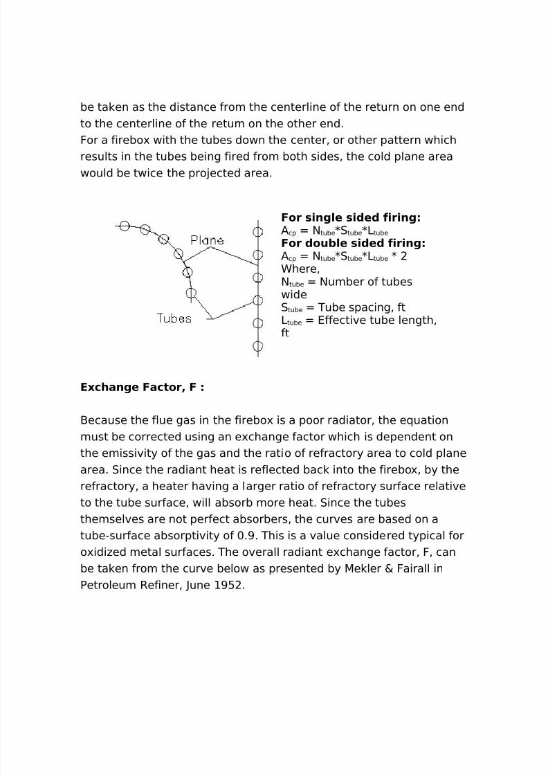
-ecause the flue gas in the firebo' is a poor radiator% the e(uationmust be corrected using an e'change factor which is dependent onthe emissivity of the gas and the ratio of refractory area to cold planearea. 0ince the radiant heat is reflected bac into the firebo'% by therefractory% a heater having a larger ratio of refractory surface relativeto the tube surface% will absorb more heat. 0ince the tubesthemselves are not perfect absorbers% the curves are based on atube"surface absorptivity of +.>. This is a value considered typical foro'idi#ed metal surfaces. The overall radiant e'change factor% F% canbe ta en from the curve below as presented by 5e ler & Fairall inPetroleum Refiner% ?une >: .
8/16/2019 17730094 Fired Heaters
http://slidepdf.com/reader/full/17730094-fired-heaters 35/141
Chere%
A 9α Ac1
The e(uivalent cold plane area% α / cp % is the product of theeffectiveness factor and the cold plane area as described above. The/ w can be described as follows%
/ w / r " α / cp
and%/ w 4ffective refractory area% ft
/ r Total refractory area% ftα / cp 4(uivalent cold plane area%ft
The total refractory area% / r% is simply the total of the refractory areae'posed to the radiant section of the heater.
F/ue 'a* Em)**) )t.
8/16/2019 17730094 Fired Heaters
http://slidepdf.com/reader/full/17730094-fired-heaters 36/141
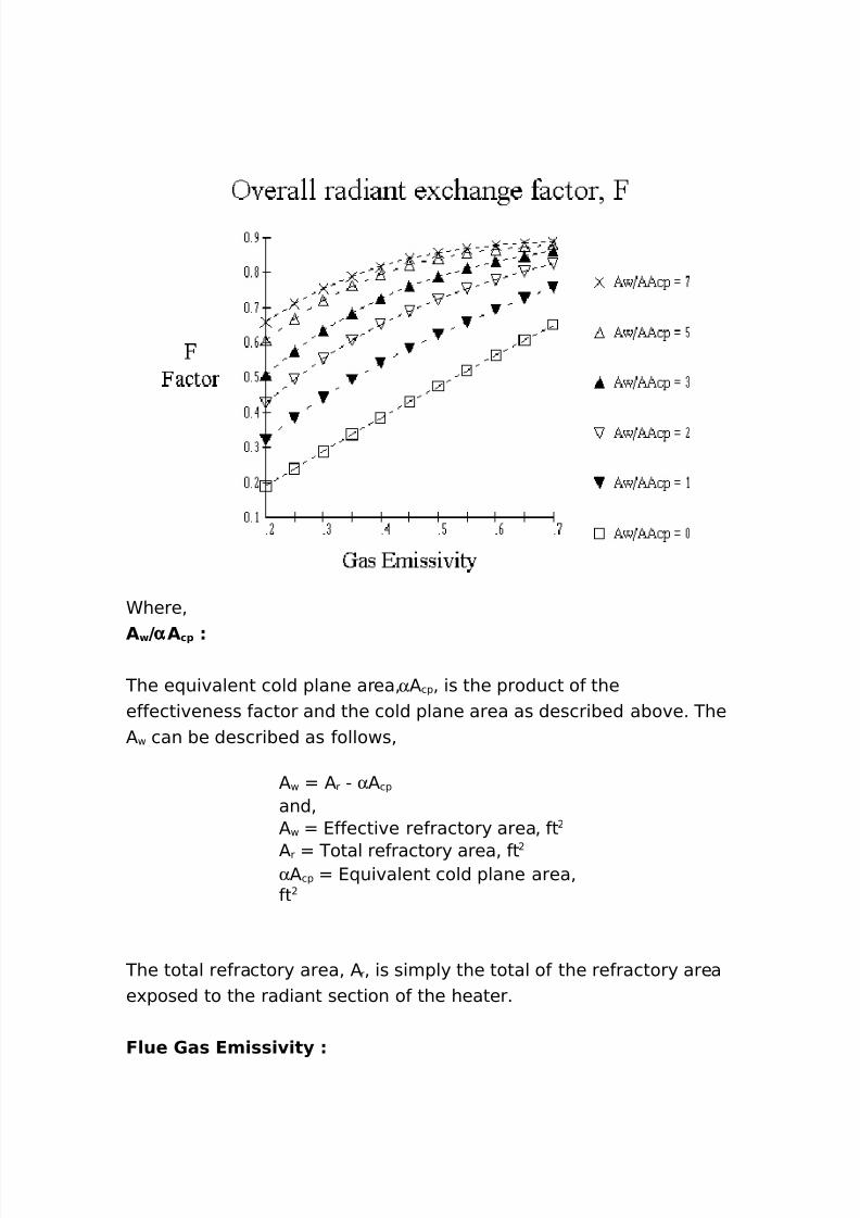
The gas emissivity can be described by the curve presented by 3oboand 4vans% at /I2H4% G nd /nnual 5eeting% $ovember >G>. The tubewall temperature has only a minor effect. Therefore% the emissivitycan be correlated as a function of P3 product and the gastemperature% T g . ariations in tube wall temperatures between ,++and ++;F cause less than B deviation from these curves.
/nd%P3 Product of the Partial Pressure of the
carbon dio'ide and water times the -eam
3ength% in atm"ft.
Chere%
Part)a/ Pre**ure Of CO ! 5 H ! O
The only constituents normally in the flue gas that contributesignificantly to the radiant emission are the carbon dio'ide and thewater% the sum of these are all that are considered. The Partialpressure of a gas component in atmAs is the mole volume fraction
8/16/2019 17730094 Fired Heaters
http://slidepdf.com/reader/full/17730094-fired-heaters 37/141
8/16/2019 17730094 Fired Heaters
http://slidepdf.com/reader/full/17730094-fired-heaters 38/141
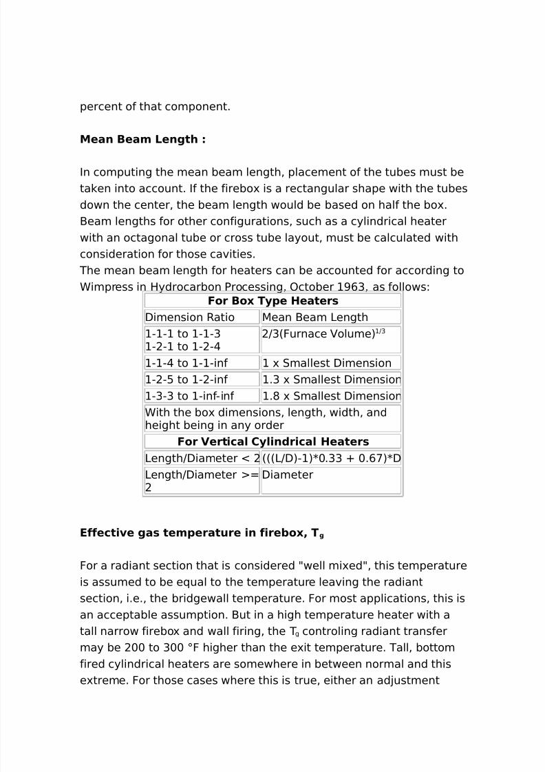
such as using another temperature in this e(uation while using thee'it temperature for the heat balance or dividing the radiant into#ones for the balance calculations% should be considered.
A erage tu+e a// tem1erature4 T
Tube wall temperature depends on the temperature of the processfluid and its transfer coefficient inside the tube% the thermalresistance of the tube wall% the heat flu'% and the fouling. Thecalculation of this temperature will be treated in another section of
this guide. The average tube wall temperature as used herein% may be one ofeither the average temperature of the front *+; face of the tube% orthe overall average for the full circumference. 0ome engineers followone method while the others go the other way. 4ither way% the overalldifference between methods is relatively small.
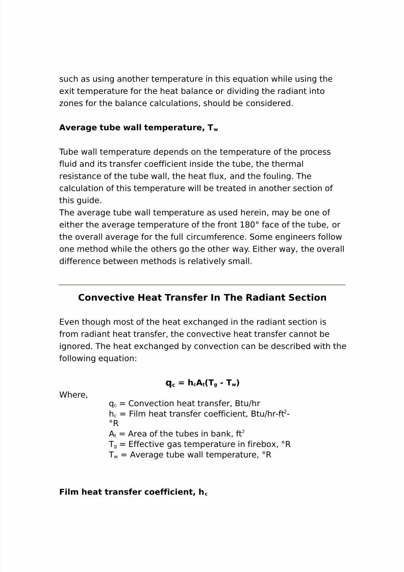
Con ect) e Heat Tran*fer In The Ra()ant Sect)on
4ven though most of the heat e'changed in the radiant section isfrom radiant heat transfer% the convective heat transfer cannot beignored. The heat e'changed by convection can be described with thefollowing e(uationL
c 7 h cA t 2Tg " T 3Chere%
( c 2onvection heat transfer% -tuJhrh c Film heat transfer coefficient% -tuJhr"ft ";R/ t /rea of the tubes in ban % ft
T g 4ffective gas temperature in firebo'% ;R T w /verage tube wall temperature% ;R
F)/m heat tran*fer coeff)c)ent4 h c
8/16/2019 17730094 Fired Heaters
http://slidepdf.com/reader/full/17730094-fired-heaters 39/141
This value cannot be calculated precisely% and is usually selected bye'perience or rule of thumb. The arrangement of the tubes as well asthe firebo' design contributes to this factor. For hori#ontal tube% cabintype heater% which is normally small in si#e% this coefficient might
.:% where on large bo' heaters with multiple tube cells% it may be ashigh as .*. ertical heaters with an 3JD less than would normally bedesigned with h c % where for an 3JD greater than .+% you could useG.+.
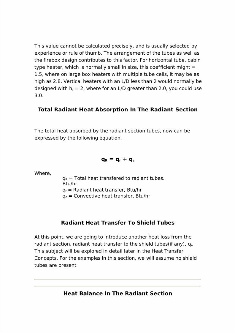
Tota/ Ra()ant Heat A+*or1t)on In The Ra()ant Sect)on
The total heat absorbed by the radiant section tubes% now can bee'pressed by the following e(uation.
R 7 r : c
Chere% ( R Total heat transfered to radiant tubes%-tuJhr( r Radiant heat transfer% -tuJhr( c 2onvective heat transfer% -tuJhr
Ra()ant Heat Tran*fer To Sh)e/( Tu+e*
/t this point% we are going to introduce another heat loss from theradiant section% radiant heat transfer to the shield tubes6if any7% ( 0 .
This sub!ect will be e'plored in detail later in the Heat Transfer2oncepts. For the e'amples in this section% we will assume no shieldtubes are present.
Heat Ba/ance In The Ra()ant Sect)on
8/16/2019 17730094 Fired Heaters
http://slidepdf.com/reader/full/17730094-fired-heaters 40/141
The procedures we have reviewed above gives us a method to eithercompute the heat absorbed% or we can calculate the temperature wewould need to transfer a specific amount of heat into our process coil.For us to ma e a heat balance% we will need to determine the firingrate necessary to maintain that temperature. This is accomplished bya heat balance around the fire bo'.
There are three primary sources of heat input to the radiant section%
the burner release% ( rls % the sensible heat of the combustion air% ( air %and the sensible heat of the fuel and any atomi#ing medium% ( other .Heat is ta en out of the radiant section by the two heat transfermethods previously e'plained% ( R and ( 0% and by losses through thecasing% ( loss % and sensible heat of the e'iting flue gas% ( out .
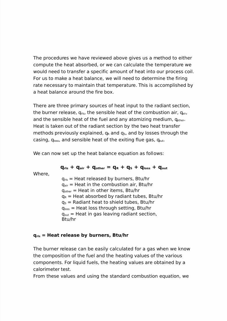
Ce can now set up the heat balance e(uation as followsL
r/* : a)r : other 7 R : S : /o** : outChere%
( rls Heat released by burners% -tuJhr( air Heat in the combustion air% -tuJhr( other Heat in other items% -tuJhr( R Heat absorbed by radiant tubes% -tuJhr( 0 Radiant heat to shield tubes% -tuJhr( loss Heat loss through setting% -tuJhr( out Heat in gas leaving radiant section%-tuJhr
r/* 7 Heat re/ea*e +. +urner*4 Btu9hr
The burner release can be easily calculated for a gas when we nowthe composition of the fuel and the heating values of the variouscomponents. For li(uid fuels% the heating values are obtained by acalorimeter test.From these values and using the standard combustion e(uation% we
8/16/2019 17730094 Fired Heaters
http://slidepdf.com/reader/full/17730094-fired-heaters 41/141
can determine the composition of the flue gas. /s an e'ample% thecombustion of methane could be stated L
CH : !O ! """ G CO ! : !H ! O)f course for fuel gases containing many more components andburning in air rather than pure o'ygen% the e(uation gets morecomplicated. Therefore% a tas that in itself is (uite simple% becomes aburden to do by hand% but can be easily accomplished by a simplecomputer program. The heating values normally used in fired heaterdesign are the LHV % lower heating values.
To try some calculations% clic the button below to open anotherwindow to do some fuel combustion calculationsL
a)r 7 Heat )n the com+u*t)on a)r4 Btu9hr
The heat available in the combustion air% such as from preheated air%or using 1as Turbine 4'haust% etc.% is ta en as the heat content above
,+ ;F% since that is the design datum temperature for fired heaters.For the purpose of this discussion% radiant heat transfer% we are notgoing to ta e this into account% i.e.% we will consider the air at ,+ ;F.
other 7 Heat )n other )tem*4 Btu9hr
The heat available in other items would include such things as thefuel when it is above ,+ ;F% atomi#ing air or steam% etc. These mustbe ta en into account in heater design% however% for the purposes ofthese discussions% we are not going to include them.
/o** 7 Heat /o** through *ett)ng4 Btu9hr
These losses% referred to as 0etting 3oss or Radiation 3oss are usuallynot calculated during heater rating calculations. They are normallyaccounted for by allowances% such as a percent of burner release or apercent of heat absorbed. 4ither way% the loss amounts to a rule ofthumb. The actual losses may be calculated for the various surfaces
8/16/2019 17730094 Fired Heaters
http://slidepdf.com/reader/full/17730094-fired-heaters 42/141
and these methods are described elsewhere.
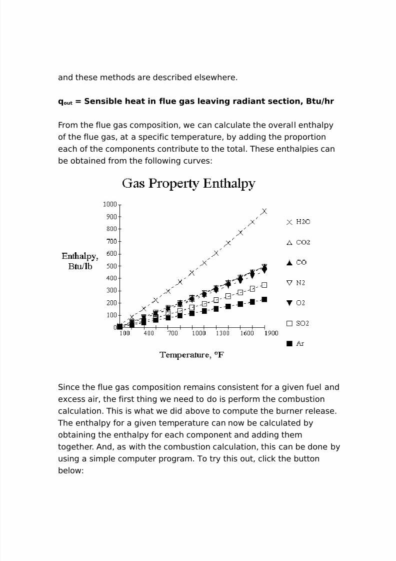
out 7 Sen*)+/e heat )n f/ue ga* /ea )ng ra()ant *ect)on4 Btu9hr
From the flue gas composition% we can calculate the overall enthalpyof the flue gas% at a specific temperature% by adding the proportioneach of the components contribute to the total. These enthalpies canbe obtained from the following curvesL
0ince the flue gas composition remains consistent for a given fuel ande'cess air% the first thing we need to do is perform the combustioncalculation. This is what we did above to compute the burner release.
The enthalpy for a given temperature can now be calculated byobtaining the enthalpy for each component and adding themtogether. /nd% as with the combustion calculation% this can be done byusing a simple computer program. To try this out% clic the buttonbelowL
8/16/2019 17730094 Fired Heaters
http://slidepdf.com/reader/full/17730094-fired-heaters 43/141
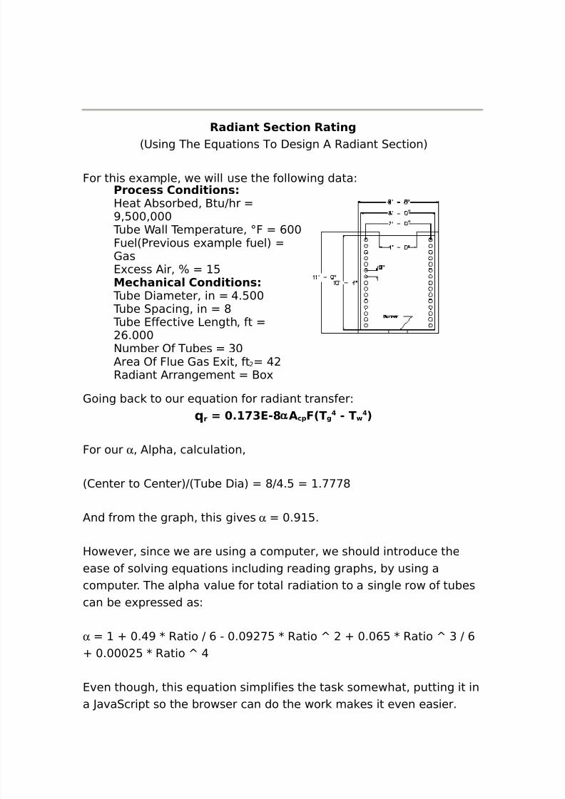
Ra()ant Sect)on Rat)ng68sing The 4(uations To Design / Radiant 0ection7
For this e'ample% we will use the following dataLProce** Con()t)on*Heat /bsorbed% -tuJhr >%:++%+++
Tube Call Temperature% ;F ,++Fuel6Previous e'ample fuel7 1as4'cess /ir% B :Mechan)ca/ Con()t)on*
Tube Diameter% in @.:++ Tube 0pacing% in * Tube 4ffective 3ength% ft
,.+++$umber )f Tubes G+/rea )f Flue 1as 4'it% ft @Radiant /rrangement -o'
1oing bac to our e(uation for radiant transferL
r 7 %# $E"? α Ac1 F2T g " T 3
For our α % /lpha% calculation%
62enter to 2enter7J6Tube Dia7 *J@.: .<<<*
/nd from the graph% this gives α +.> :.
However% since we are using a computer% we should introduce theease of solving e(uations including reading graphs% by using acomputer. The alpha value for total radiation to a single row of tubescan be e'pressed asL
α O +.@> K Ratio J , " +.+> <: K Ratio Q O +.+,: K Ratio Q G J ,O +.+++ : K Ratio Q @
4ven though% this e(uation simplifies the tas somewhat% putting it ina ?ava0cript so the browser can do the wor ma es it even easier.
8/16/2019 17730094 Fired Heaters
http://slidepdf.com/reader/full/17730094-fired-heaters 44/141
/ cp 6$o. Tubes7K0paceK64ff. 3ength7 G+K*J K ,.+++ : +.+
α / cp +.> : K : +.+ @<:.*
/ r CK3K O CKHK O HK3K "4'it area K3 *K ,K O*K +.GGGK O +.GGGK ,K "@ %+<,.,@@
/ w / r " α / cp +<,.,@@ " @<:.* ,++.*@@
/ wJα / cp ,++.*@@ J @<:.* . , *
To calculate the 4'change Factor% F% we need the flue gas emissivity%
which we can get by interpolation from the curve presented above. /spreviously indicated% the Partial Pressure of the gas can be assumedto be the sum of the partial pressures of the 2) O H ). If we go bacto the Fuel 1as 2ombustion calculation% we find that the mole percentof the 2) +.+*::*, and the H ) +. < *,% so the sum is+.+*::*, O +. < *, +. :<*.
The beam length can then be obtained from the above table.C L H L 3 *L +.GL , L .GLG.G%so%-eam 3ength JG6*K +.GGGK ,7 JG *.,+and%P3 +. :<* K *.,+ . <@however% in eeping with the other correlations% we should go aheadand setup a ?ava0cript to solve the 5ean -eam 3ength% withoutmanually interpolating the table.
8/16/2019 17730094 Fired Heaters
http://slidepdf.com/reader/full/17730094-fired-heaters 45/141
The first thing we notice with this answer is that it doesnAt match thehand calculated value. This is because the curve fit to facilitate all thetable conditions and those in between% will not give the same value aswe get when we select one formula or the ne't% with no transition.-ut% the calculated value is fine for our heat transfer calculations.
The emissivity curve re(uires that we now the T g% which we donAtnow at this time. 0o for these calculations% we are going to initially
assume this to be :++; F. -ut% as above% we can now interpret thecomplicated emissivity curve with our browser.
0o%( r +. <G4"*K@<:.*K+.:><K66 :++O@,+7Q@ " 6,++O@,+7Q@7 ,%,G %<>@ -tuJhr/nd%( c .:K> *.> *K6 :++",++7 % @+%:G> -tuJhr
Therefore%( R ( rO ( c ,%,G %<>@ O % @+%:G> <%*< %GGG -tuJhr
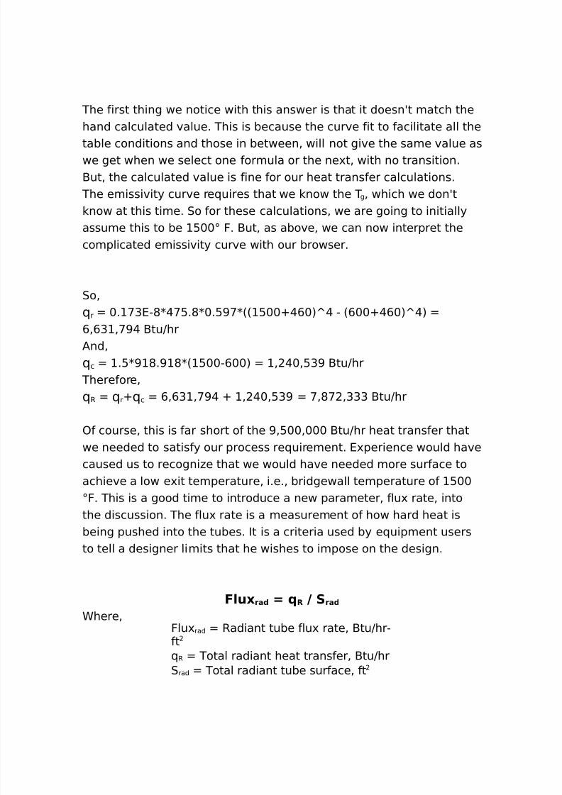
)f course% this is far short of the >%:++%+++ -tuJhr heat transfer thatwe needed to satisfy our process re(uirement. 4'perience would havecaused us to recogni#e that we would have needed more surface toachieve a low e'it temperature% i.e.% bridgewall temperature of :++;F. This is a good time to introduce a new parameter% flu' rate% intothe discussion. The flu' rate is a measurement of how hard heat isbeing pushed into the tubes. It is a criteria used by e(uipment usersto tell a designer limits that he wishes to impose on the design.
F/u0 ra( 7 R 9 S ra(
Chere%Flu' rad Radiant tube flu' rate% -tuJhr"ft( R Total radiant heat transfer% -tuJhr0 rad Total radiant tube surface% ft
8/16/2019 17730094 Fired Heaters
http://slidepdf.com/reader/full/17730094-fired-heaters 46/141
8/16/2019 17730094 Fired Heaters
http://slidepdf.com/reader/full/17730094-fired-heaters 47/141
C fuel Fuel flow rate% lbJhr3hv fuel 3ower heating value of the fuel%-tuJlb
/nd we can restate% ( out in the following terms%
out 7 26 fue/ 8Rat)o A)rFue/ :6 fue/ 38Enth fg
Chere%Ratio /irFuel /ir to fuel ratio% lbJlb4nth fg 4nthalpy of flue gas%-tuJlb
ou will notice that all of these variables% we have a value for% e'ceptthe amount of fuel% C fuel . 0o it becomes a very simple matter torearrange the e(uation and solve it for the amount of fuel re(uired tomaintain the T g% that we determined we needed in the previouscalculation.
6 fue/ 8Lh fue/ 7 R : 6 fue/ 8Lh fue/ 8 % #= :26 fue/ 8Rat)o A)rFue/ :6 fue/ 38Enth fg
Then% rearranging the e(uation% it becomes%
6 fue/ 7 R 9 2Lh fue/ " 2Lh fue/ 8 % #= : Rat)o A)rFue/ 8Enth fg :Enth fg 33
0ubstituting the values we developed earlier%
6 fue/ 7 >= 9 2! $ = " 2! $ =8 % #= :#?% >@ 8 $%# #>: $%# #>33 7 ? $% >=$
0o the burner release and the flue gas flow%
r/* 7 ? $% >=$8! $ = 7 # 4#=!4 $ Btu9hr6 fg 7 ? $% ?=$8#?% >@ :? $% ?=$ 7 #@4@> /+9hr
/nd% what we really wanted to now% the efficiency of the heater%
8/16/2019 17730094 Fired Heaters
http://slidepdf.com/reader/full/17730094-fired-heaters 48/141
Eff)c)enc. 7 >= 9# #=! $8# 7 ==%$?
This concludes the review of Radiant 0ection Design% but the followingscript will provide a window where all of the formulas can be testedfor various designs.
Sh)e/( Sect)on De*)gn
0hield section normally refers to the first several rows in theconvection section% which 9shield9 the remaining tubes from the direct
radiation occurring in the radiant section. The shield section normallyconsists of two to three rows of bare tubes% but the arrangementvaries widely for the many different heater designs.
This section of Fired Heater Design is divided into three main areas%which can be selected from the sub!ect drop down bo' above or youmay use the !ump lin s below to go to a section. ou may also useyour browser 9bac button9 to return to where you were.
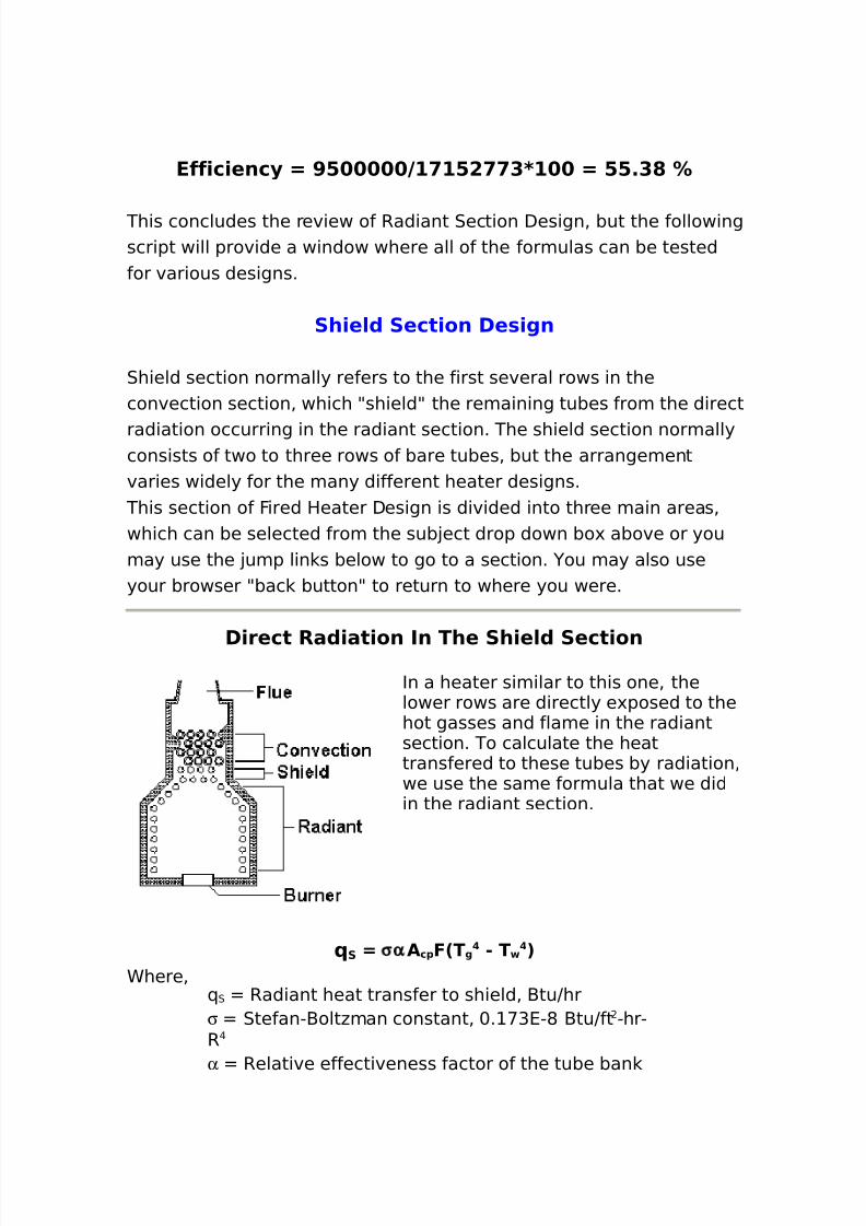
D)rect Ra()at)on In The Sh)e/( Sect)onIn a heater similar to this one% thelower rows are directly e'posed to thehot gasses and flame in the radiantsection. To calculate the heattransfered to these tubes by radiation%we use the same formula that we didin the radiant section.
S 7 σα Ac1 F2T g " T 3Chere%
( 0 Radiant heat transfer to shield% -tuJhrσ 0tefan"-olt#man constant% +. <G4"* -tuJft "hr"R@
α Relative effectiveness factor of the tube ban
8/16/2019 17730094 Fired Heaters
http://slidepdf.com/reader/full/17730094-fired-heaters 49/141
/ cp 2old plane area of the tube ban % ftF 4'change factor
T g 4ffective gas temperature in firebo'% ;R T w /verage tube wall temperature% ;R
Re/at) e Effect) ene** Factor4 α
0ince all the heat directed toward this ban of tubes% leaves theradiant section and is absorbed by the tubes% the relative absorptioneffectiveness factor% α % for the shield tubes can be ta en to be e(ual
to one.
Co/( P/ane Area4 A c1
The cold plane area for the shield section is e(ual to the cold planearea of the first row of tubes.
/ cp $ tube K0tube K3tube
Chere%$ tube $umber of tubes wide0 tube Tube spacing% ft3 tube Tube length% ft
E0change Factor4 F Effect) e ga* tem1erature )n f)re+o04 T g
A erage tu+e a// tem1erature4 T
The values used for these factors are the same as the values to beused in the radiant section. The difference is% when there is a shieldsection% which is receiving direct radiation% the α / cp for the radiantand the shield are calculated independently% then added together tocalculate the e'change factor% F.
0o the e(uation for / w% becomesL
A 7 A r " 22 α Ac1 3ra( : 2 α Ac1 3*h/( 3
8/16/2019 17730094 Fired Heaters
http://slidepdf.com/reader/full/17730094-fired-heaters 50/141
/nd for / wJα / cp %
A 9α Ac1 7 A 9 22α Ac1 3ra( : 2 α Ac1 3*h/( 3Chere%/ w 4ffective refractory area% ft/ r Total refractory area% ft6α / cp 7rad 4(uivalent cold plane area of radiant tubes%ft6α / cp 7shld 4(uivalent cold plane area of shield tubes%ft
Therefore% the corrected formula for the radiant heat transfer in theradiant section% when a shield section is present becomes%
tot"ra( 7 σ α Ac1 3ra( F2T g " T 3 : σ α Ac1 3*h/( F2T g " T 3
/nd total transfer to radint tubes%
R 7 σ α A c1 3ra( F2T g " T 3 : c
/nd radiant only transfer to shield tubes%
S 7 σ α Ac1 3*h/( F2T g " T 3
NOTE It should be noted here% that the convective transfer% ( c% forthe radiant section remains as it was described an( )t (oe* notapply to the shield tubes. The convection transfer to the shield tubesis calculated the same as for other convection tubes. It is also%important to remember that the T g applies to the gas temperatureafter the shield radiant heat is removed% but before the shieldconvection heat is removed.
$ow that we have calculated the direct radiant transfer to the shieldtubes% how do we apply it The heat can be distributed to the first tworows using the proportions e(uivalent to the alpha factor curve fordirect to first row compared to total to two rows. This results inappro'imately <<B to the first row and GB to the second. Thisassumption would appear to be sufficient% even though some of the

8/16/2019 17730094 Fired Heaters
http://slidepdf.com/reader/full/17730094-fired-heaters 51/141
radiant heat would also be directed to the third row. -ut the amountgoing to the third row would be small and this approach isconservative% since it would assume more heat in the first two rowswhere high tube flu's and wall temperatures could be a problem.
In"D)rect4 Non"Lum)nou* Ra()at)on In The Sh)e/(Sect)on
8/16/2019 17730094 Fired Heaters
http://slidepdf.com/reader/full/17730094-fired-heaters 52/141
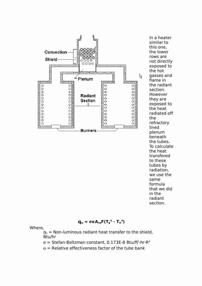
In a heatersimilar tothis one%the lowerrows arenot directlye'posed tothe hotgasses andflame inthe radiantsection.However
they aree'posed tothe heatradiated offtherefractorylinedplenumbeneaththe tubes.
To calculatethe heattransferedto thesetubes byradiation%we use thesameformulathat we didin the
radiantsection.
n 7 σα Ac1 F2T g " T 3Chere%
( n $on"luminous radiant heat transfer to the shield%-tuJhrσ 0tefan"-olt#man constant% +. <G4"* -tuJft "hr"R @
α Relative effectiveness factor of the tube ban
8/16/2019 17730094 Fired Heaters
http://slidepdf.com/reader/full/17730094-fired-heaters 53/141
/ cp 2old plane area of the tube ban % ftF 4'change factor
T g 4ffective gas temperature in firebo'% ;R T w /verage tube wall temperature% ;R
Re/at) e Effect) ene** Factor4 α
0ince all the radiant heat directed toward this ban of tubes isabsorbed by the tubes in the convection% the relative absorptioneffectiveness factor% α % for the shield tubes can be ta en to be e(ual
to one.
Co/( P/ane Area4 A c1
The cold plane area for the shield section is e(ual to the cold planearea of the first row of tubes.
/ cp $ tube K0tube K3tube
Chere%$ tube $umber of tubes wide0 tube Tube spacing% ft3 tube Tube length% ft
E0change Factor4 F Effect) e ga* tem1erature )n f)re+o04 T g
A erage tu+e a// tem1erature4 T
The values used for these factors are calculated the same way as wasdescribed in the radiant design section. The / r factor being the onlye'ception. This factor is the inside area of the plenum below thetubes. The openings where the flue gas enters are normally ignored%since the ducting connecting them perform the same reflectivepurpose.
This type of shield calculation is totally independent of the radiantsection where the heat balance is performed as if there where no
8/16/2019 17730094 Fired Heaters
http://slidepdf.com/reader/full/17730094-fired-heaters 54/141
shield. The radiant heat from this calculation will reduce the gastemperature used in the convection transfer calculation.
Sh)e/( Sect)on Rat)ng
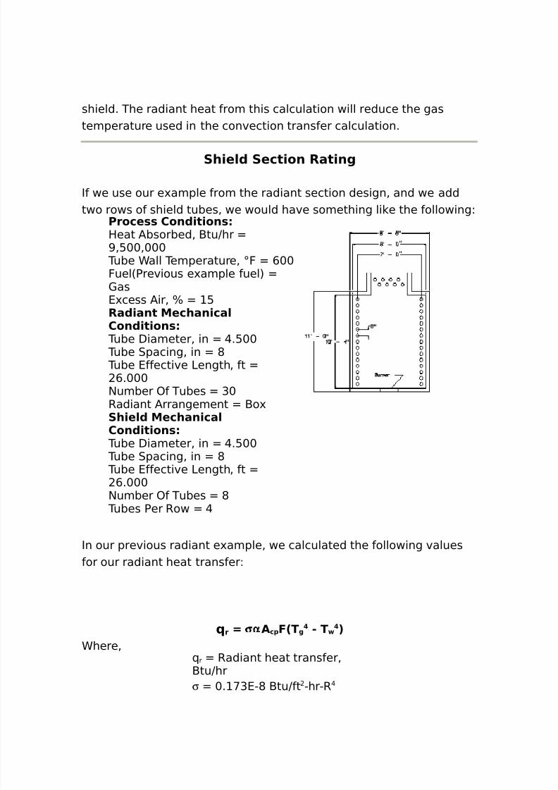
If we use our e'ample from the radiant section design% and we addtwo rows of shield tubes% we would have something li e the followingL
Proce** Con()t)on*Heat /bsorbed% -tuJhr >%:++%+++
Tube Call Temperature% ;F ,++
Fuel6Previous e'ample fuel7 1as4'cess /ir% B :Ra()ant Mechan)ca/Con()t)on*
Tube Diameter% in @.:++ Tube 0pacing% in * Tube 4ffective 3ength% ft
,.+++$umber )f Tubes G+Radiant /rrangement -o'Sh)e/( Mechan)ca/Con()t)on*
Tube Diameter% in @.:++ Tube 0pacing% in * Tube 4ffective 3ength% ft
,.+++$umber )f Tubes *
Tubes Per Row @
In our previous radiant e'ample% we calculated the following valuesfor our radiant heat transferL
r 7 σα Ac1 F2T g " T 3Chere%
( r Radiant heat transfer%-tuJhr
σ +. <G4"* -tuJft "hr"R@
8/16/2019 17730094 Fired Heaters
http://slidepdf.com/reader/full/17730094-fired-heaters 55/141
α +.> :/ cp : +.+ ft
F +.:*: T g +,G% ;R T w +,+% ;R
-ut% as we have reviewed in the shield design% we must nowrecalculate the e'change factor% F% which will change our gas e'ittemperature% T g% as well.
A 922α Ac1 3ra( : 2 α Ac1 3*h/( 3
The / w can be described as follows%
/ w / r " 66α / cp 7rad O 6 α / cp 7shld 7and%/ w 4ffective refractory area% ft/ r Total refractory area% ft
α / cp 4(uivalent cold plane area%ft
The total refractory area% / r% is simply the total of the refractory areae'posed to the radiant section of the heater. This value may havechanged since the original heater only re(uired e'it flue gas outlets%where this heater now has a full length opening the width of theshield section.
/rea of shield section @K*J K , ,>.GGG ft/ r *K +.GGGK O*K ,K O +.GGGK ,K ",>.GGG +@> ft6α / cp 7rad +.> :KG+K*J K , @<:.* ft6α / cp 7shld .+K@K*J K , ,>.GGG ftso%/ w +@> " @<:.* " ,>.GGG :+G.*,<and%/ wJ66α / cp 7rad O 6 α / cp 7shld 7 :+G.*,<J6@<:.*O,>.GGG7 +.> @G
8/16/2019 17730094 Fired Heaters
http://slidepdf.com/reader/full/17730094-fired-heaters 56/141
The beam length will remain the same as the previous e'ample% sincewe have not changed our firebo' si#e.
The partial pressure of the flue gas will remain the same since fluegas composition has not been changed.
The emissivity% however% does change since it is dependent on thetemerature of the gas% T g .
ou may wish to go bac to the radiant section and review these
calculations in detail% at this time. If not% select the button below toopen a window where we can do a few calculations to see the resultsof adding a shield section.
Con ect)on Sect)on De*)gn
In the convection section% heat is transferred by both radiation andconvection. The convection transfer coefficients for fin and stud tubes
are e'plored here as well as bare tube transfer. The short beamradiation is treated separately from the convection transfer below.
This section of Fired Heater Design is divided into five main areas%which can be selected from the sub!ect drop down bo' above or youmay use the !ump lin s below to go to a section. ou may also useyour browser 9bac button9 to return to where you were.
Con ect)on Tran*fer4 Bare Tu+e*
O era// Heat Tran*fer Coeff)c)ent4 U o
U o 7 #9R to
Chere%8 o )verall heat transfer coefficient% -tuJhr"ft "FR to Total outside thermal resistance% hr"ft "FJ-tu
/nd%Rto R o O R wo O R io
8/16/2019 17730094 Fired Heaters
http://slidepdf.com/reader/full/17730094-fired-heaters 57/141
Ro )utside thermal resistance% hr"ft "FJ-tuRwo Tube wall thermal resistance% hr"ft "FJ-tuRio Inside thermal resistance% hr"ft "FJ-tu
/nd the resistances are computed as%Ro Jh e
Rwo 6twJ K w76/ oJ/ w7R io 66 Jh i7OR fi76/ oJ/ i7
Chere%
h e 4ffective outside heat transfer coefficient% -tuJhr"ft "Fh i Inside film heat transfer coefficient% -tuJhr"ft "Ft w Tubewall thic ness% in
w Tube wall thermal conductivity% -tuJhr"ft"F/ o )utside tube surface area% ft Jft/ w 5ean area of tube wall% ft Jft/ i Inside tube surface area% ft JftRfi Inside fouling resistance% hr"ft "FJ-tu
In*)(e f)/m heat tran*fer coeff)c)ent4 h) The inside heat transfer coefficient calculation procedure is covered indetail% elsewhere in this course.
Effect) e out*)(e heat tran*fer coeff)c)ent4 heh e 7 #92#92h c :h r 3:R fo 3
Chere%h c )utside heat transfer coefficient% -tuJhr"ft "F
h r )utside radiation heat transfer coefficient% -tuJhr"ft "FRfo )utside fouling resistance% hr"ft "FJ-tu
Out*)(e f)/m heat tran*fer coeff)c)ent4 hc
The bare tube heat transfer film coefficient% h c% can be described bythe following e(uations.For a staggered tube arrangement%
8/16/2019 17730094 Fired Heaters
http://slidepdf.com/reader/full/17730094-fired-heaters 58/141
h c 7 %$$8, + 2#!9( o 322c1 8µ +39, +3#9$ 22( o 9#!32' n 9µ +333 %@
/nd for an inline tube arrangement%
h c 7 %!@8, + 2#!9( o 322c1 8µ +39, +3#9$ 22( o 9#!32' n 9µ +333 %@
Chere%h c 2onvection heat transfer coefficient% -tuJhr"ft "Fd o Tube outside diameter% in
b 1as thermal conductivity% -tuJhr"ft"Fc p 1as heat capacity% -tuJlb"Fµb 1as dynamic viscosity% lbJhr"ft1 n 5ass velocity of gas% lbJhr"ft
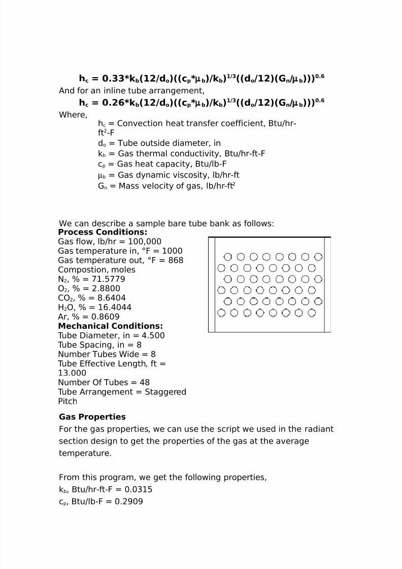
Ce can describe a sample bare tube ban as followsLProce** Con()t)on*1as flow% lbJhr ++%+++1as temperature in% ;F +++1as temperature out% ;F *,*2ompostion% moles$ % B < .:<<>) % B .**++
2) % B *.,@+@H )% B ,.@+@@/r% B +.*,+>Mechan)ca/ Con()t)on*
Tube Diameter% in @.:++ Tube 0pacing% in *$umber Tubes Cide *
Tube 4ffective 3ength% ft G.+++
$umber )f Tubes @* Tube /rrangement 0taggeredPitch
'a* Pro1ert)e*For the gas properties% we can use the script we used in the radiantsection design to get the properties of the gas at the averagetemperature.
From this program% we get the following properties%
b% -tuJhr"ft"F +.+G :c p% -tuJlb"F +. >+>
8/16/2019 17730094 Fired Heaters
http://slidepdf.com/reader/full/17730094-fired-heaters 59/141
8/16/2019 17730094 Fired Heaters
http://slidepdf.com/reader/full/17730094-fired-heaters 60/141
FJ-tu
/nd%Rto R o O R wo O R io
Ro )utside thermal resistance% hr"ft "FJ-tuRwo Tube wall thermal resistance% hr"ft "FJ-tuRio Inside thermal resistance% hr"ft "FJ-tu
/nd the resistances are computed as%Ro Jh e
Rwo 6twJ K w76/ oJ/ w7R io 66 Jh i7OR fi76/ oJ/ i7
Chere%h e 4ffective outside heat transfer coefficient% -tuJhr"ft "Fh i Inside film heat transfer coefficient% -tuJhr"ft "Ft w Tubewall thic ness% in
w Tube wall thermal conductivity% -tuJhr"ft"F/ o Total outside surface area% ft Jft/ w 5ean area of tube wall% ft Jft/ i Inside tube surface area% ft JftRfi Inside fouling resistance% hr"ft "FJ-tu
In*)(e f)/m heat tran*fer coeff)c)ent4 h) The inside heat transfer coefficient calculation procedure is covered indetail% elsewhere in this course.
Effect) e out*)(e heat tran*fer coeff)c)ent4 h e
h e 7 h o 2E8A fo :A 1o 39Ao
Chere%h o /verage outside heat transfer coefficient% -tuJhr"ft "F4 Fin efficiency/ o Total outside surface area% ft Jft/ fo Fin outside surface area% ft Jft/ po )utside tube surface area% ft Jft
8/16/2019 17730094 Fired Heaters
http://slidepdf.com/reader/full/17730094-fired-heaters 61/141
/nd%A erage out*)(e heat tran*fer coeff)c)ent4 h o
h o 7 #92#92h c :h r3:R fo 3Chere%
h c )utside heat transfer coefficient% -tuJhr"ft "Fh r )utside radiation heat transfer coefficient% -tuJhr"ft "FRfo )utside fouling resistance% hr"ft "FJ-tu
Out*)(e f)/m heat tran*fer coeff)c)ent4 hc
h c 7 8' n 8c 1 2, +92c1 8µ + 33 %@
Chere% ! 2olburn heat transfer factor1 n 5ass velocity based on net free area% lbJhr"ftc p Heat capacity% -tuJlb"F
b 1as thermal conductivity% -tuJhr"ft"Fµb 1as dynamic viscosity% lbJhr"ft
Co/+urn heat tran*fer factor4 7 C # 8C $ 8C =2( f 9( o 3 %=22T+ : @ 392T *: @ 33 %!=
Chere%2 Reynolds number correction2 G 1eometry correction2 : $on"e(uilateral & rowcorrectiond f )utside diameter of fin% ind o )utside diameter of tube% in
T b /verage gas temperature% F T s /verage fin temperature% F
Re.no/(* num+er correct)on4 C #
C# 7 %!=8R e" %$=
Chere%Re Reynoldsnumber
8/16/2019 17730094 Fired Heaters
http://slidepdf.com/reader/full/17730094-fired-heaters 62/141
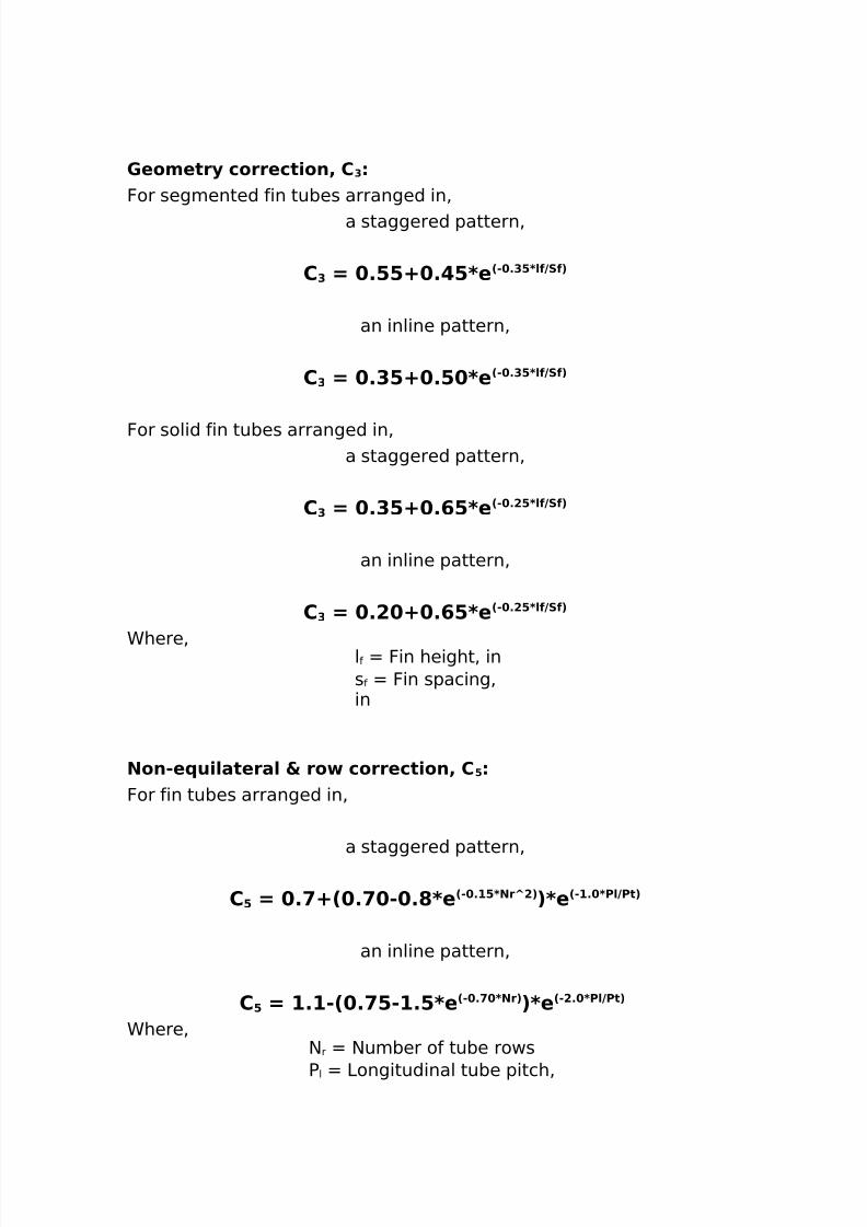
'eometr. correct)on4 C $
For segmented fin tubes arranged in%a staggered pattern%
C$ 7 %==: % =8e 2" %$=8/f9Sf3
an inline pattern%
C$ 7 %$=: %= 8e 2" %$=8/f9Sf3
For solid fin tubes arranged in%a staggered pattern%
C$ 7 %$=: %@=8e 2" %!=8/f9Sf3
an inline pattern%
C$ 7 %! : %@=8e 2" %!=8/f9Sf3
Chere% lf Fin height% ins f Fin spacing%in
Non"e u)/atera/ 5 ro correct)on4 C =
For fin tubes arranged in%
a staggered pattern%
C= 7 % :2 % " %?8e 2" %#=8NrJ!3 38e 2"#% 8P/9Pt3
an inline pattern%
C= 7 #%#"2 % ="#%=8e 2" % 8Nr338e 2"!% 8P/9Pt3 Chere%
$ r $umber of tube rows
P l 3ongitudinal tube pitch%
8/16/2019 17730094 Fired Heaters
http://slidepdf.com/reader/full/17730094-fired-heaters 63/141
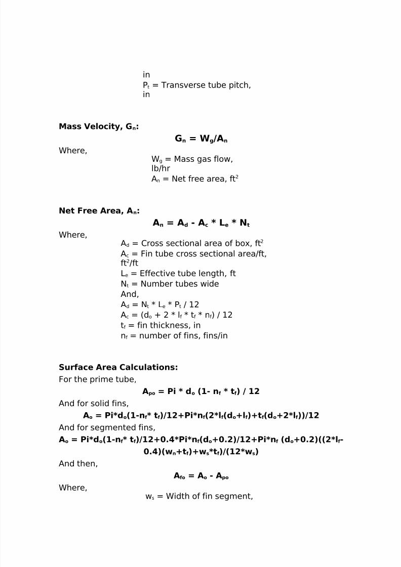
inP t Transverse tube pitch%in
Ma** Ve/oc)t.4 ' n
' n 7 6 g 9An
Chere%C g 5ass gas flow%lbJhr/ n $et free area% ft
Net Free Area4 A n
An 7 A ( " A c 8 L e 8 N t
Chere%/ d 2ross sectional area of bo'% ft/ c Fin tube cross sectional areaJft%ft Jft3e 4ffective tube length% ft$ t $umber tubes wide
/nd%/ d $ t K 3e K Pt J / c 6d o O K l f K t f K n f 7 J t f fin thic ness% inn f number of fins% finsJin
Surface Area Ca/cu/at)on*For the prime tube%
A1o 7 P) 8 ( o 2#" n f 8 t f 3 9 #!/nd for solid fins%
Ao 7 P)8( o 2#"n f 8 t f 39#!:P)8n f 2!8/ f 2( o :/ f 3:t f 2( o :!8/ f 339#!/nd for segmented fins%Ao 7 P)8( o 2#"n f 8 t f 39#!: % 8P)8n f 2( o : %!39#!:P)8n f 2( o : %!322!8/ f "
% 32 n :t f 3: *8t f 392#!8 *3/nd then%
A fo 7 A o " A 1o
Chere%w s Cidth of fin segment%
8/16/2019 17730094 Fired Heaters
http://slidepdf.com/reader/full/17730094-fired-heaters 64/141
in
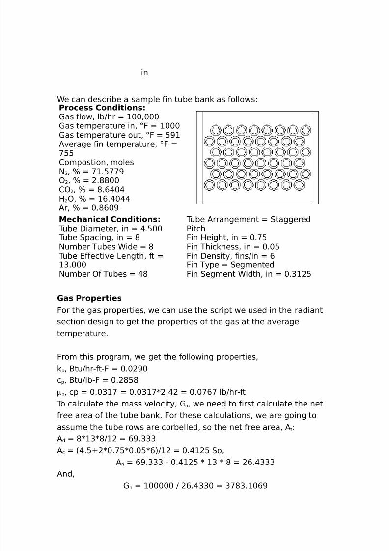
Ce can describe a sample fin tube ban as followsLProce** Con()t)on*1as flow% lbJhr ++%+++1as temperature in% ;F +++1as temperature out% ;F :>/verage fin temperature% ;F <::2ompostion% moles$ % B < .:<<>) % B .**++
2) % B *.,@+@H )% B ,.@+@@/r% B +.*,+>Mechan)ca/ Con()t)on*
Tube Diameter% in @.:++ Tube 0pacing% in *$umber Tubes Cide *
Tube 4ffective 3ength% ft G.+++
$umber )f Tubes @*
Tube /rrangement 0taggeredPitchFin Height% in +.<:Fin Thic ness% in +.+:Fin Density% finsJin ,Fin Type 0egmentedFin 0egment Cidth% in +.G :
'a* Pro1ert)e*For the gas properties% we can use the script we used in the radiantsection design to get the properties of the gas at the averagetemperature.
From this program% we get the following properties%b% -tuJhr"ft"F +.+ >+
c p% -tuJlb"F +. *:*µb% cp +.+G < +.+G <K .@ +.+<,< lbJhr"ft
To calculate the mass velocity% 1 n% we need to first calculate the netfree area of the tube ban . For these calculations% we are going toassume the tube rows are corbelled% so the net free area% / nL/ d *K GK*J ,>.GGG/ c 6@.:O K+.<:K+.+:K,7J +.@ : 0o%
/ n ,>.GGG " +.@ : K G K * ,.@GGG/nd%
1 n +++++ J ,.@GG+ G<*G. +,>
8/16/2019 17730094 Fired Heaters
http://slidepdf.com/reader/full/17730094-fired-heaters 65/141
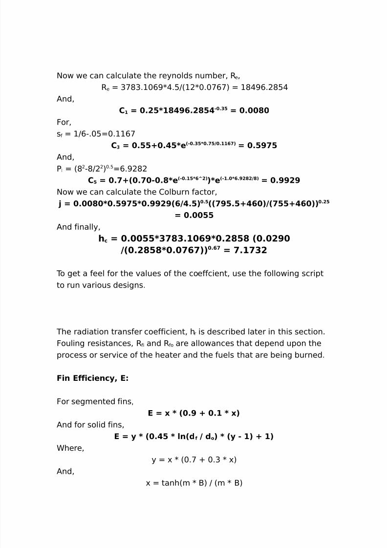
$ow we can calculate the reynolds number% R e %Re G<*G. +,>K@.:J6 K+.+<,<7 *@>,. *:@
/nd%C# 7 %!=8#? >@%!?= " %$= 7 % ?
For%s f J,".+: +. ,<
C$ 7 %==: % =8e 2" %$=8 % =9 %##@ 3 7 %=> =/nd%P l 6* "*J 7+.: ,.> *
C= 7 % :2 % " %?8e 2" %#=8@J!3 38e 2"#% 8@%>!?!9?3 7 %>>!>
$ow we can calculate the 2olburn factor% 7 % ? 8 %=> =8 %>>!>2@9 %=3 %=22 >=%=: @ 392 ==: @ 33 %!=
7 % ==/nd finally%
h c 7 % ==8$ ?$%# @>8 %!?=? 2 % !>92 %!?=?8 % @ 33 %@ 7 %# $!
To get a feel for the values of the coeffcient% use the following script
to run various designs.
The radiation transfer coefficient% h r is described later in this section.Fouling resistances% R fi and R fo are allowances that depend upon theprocess or service of the heater and the fuels that are being burned.
F)n Eff)c)enc.4 E
For segmented fins%E 7 0 8 2 %> : %# 8 03
/nd for solid fins%E 7 . 8 2 % = 8 /n2( f 9 ( o 3 8 2. " #3 : #3
Chere%y ' K 6+.< O +.G K '7
/nd%' tanh6m K -7 J 6m K -7
8/16/2019 17730094 Fired Heaters
http://slidepdf.com/reader/full/17730094-fired-heaters 66/141
Chere%- l f O 6t f J 7
For segmented fins%m 6h o 6t f O w s7 J 6, K f K t f K ws77+.:
/nd for solid fins%m 6h o J 6, K f K t f 77+.:
F)n T)1 Tem1erature4 T *
The average fin tip temperature is calculated as follows%T* 7 T g : 2T " T g 3 8 #922e #% # !mB :e "#% # !mB 39!3
Ma0)mum F)n T)1 Tem1erature4 T fm
The ma'imum fin tip temperature is calculated as follows%T*m 7 T m : θ 2Tgm " T m 3
Chere% T sm 5a'imum Fin Tip Temperature% F T gm 5a'imum 1as Temperature% F T wm 5a'imum Tube Call Temperature% F
/nd%
8/16/2019 17730094 Fired Heaters
http://slidepdf.com/reader/full/17730094-fired-heaters 67/141
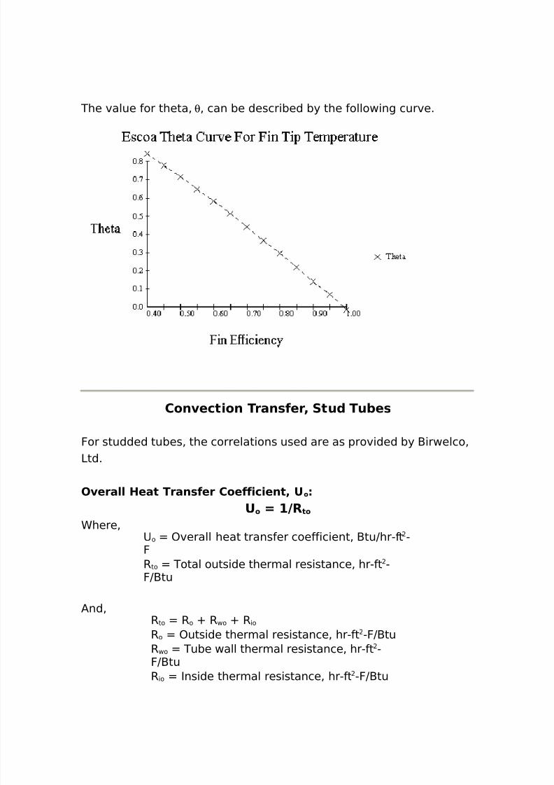
The value for theta% θ% can be described by the following curve.
Con ect)on Tran*fer4 Stu( Tu+e*
For studded tubes% the correlations used are as provided by -irwelco%3td.
O era// Heat Tran*fer Coeff)c)ent4 U o
U o 7 #9R to
Chere%8 o )verall heat transfer coefficient% -tuJhr"ft "
FR to Total outside thermal resistance% hr"ft "FJ-tu
/nd%Rto R o O R wo O R io
Ro )utside thermal resistance% hr"ft "FJ-tuRwo Tube wall thermal resistance% hr"ft "FJ-tuRio Inside thermal resistance% hr"ft "FJ-tu
8/16/2019 17730094 Fired Heaters
http://slidepdf.com/reader/full/17730094-fired-heaters 68/141
/nd the resistances are computed as%Ro Jh e
Rwo 6twJ6 K w776/ oJ/ w7R io 66 Jh i7OR fi76/ oJ/ i7
Chere%h e 4ffective outside heat transfer coefficient% -tuJhr"ft "Fh i Inside film heat transfer coefficient% -tuJhr"ft "Ft w Tubewall thic ness% in
w Tube wall thermal conductivity% -tuJhr"ft"F
/ o )utside surface area% ft Jft/ w 5ean area of tube wall% ft Jft/ i Inside tube surface area% ft JftRfi Inside fouling resistance% hr"ft "FJ-tu
Effect) e out*)(e heat tran*fer coeff)c)ent4 h e
For staggered and inline pitch%h e 7 2h *o 8E8A fo :h t 8A 1o 39Ao
Chere% h t -ase tube outside heat transfer coefficient% -tuJhr"ft "Fh so 0tud outside heat transfer coefficient% -tuJhr"ft "F/ o Total outside surface area% ft Jft/ fo 0tud outside surface area% ft Jft/ po Tube outside surface area% ft Jft
Inline pitch correction%h e 7 h e 82( o 9P /3 %$$$
Chere%d o )utside tube diameter% inP l 3ongitudinal pitch of tubes%in
Ba*e tu+e out*)(e heat tran*fer coeff)c)ent4 h t
h t 7 2 % # 9( o%$$$ 32' n 9# 3 %@2T+ : @ 3 %$
/nd the stud coefficient%h s +.>G,K61 nJ +++7 +.,< 6TbO@,+7 +.G
Cith fouling%
8/16/2019 17730094 Fired Heaters
http://slidepdf.com/reader/full/17730094-fired-heaters 69/141
h so J6 Jh sOR fo7Chere%
h s 0tud outside heat transfer coefficient% -tuJhr"ft "F1 n 5ass velocity of flue gas% lbJhr"ft
T b /verage gas temperature% F
Stu( eff)c)enc.4 EE 7 #922e 0 :e "039#%>= 3
Chere%S 3 sJ 66 Khso 7J6 sKDsJ 77+.:
/nd%3 s 3ength of stud% inDs Diameter of stud% in
s 2onductivity of stud% -tuJhr"ft"F
The following script will allow us calculate the coeffcient for studtubes.
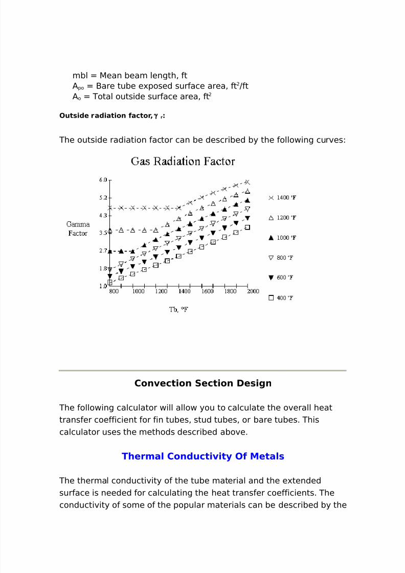
Short Beam4 Ref/ect) e Ra()at)on
The gas radiation factor% h r% can be calculated from the followingcorrelations. This factor is used in calculating the overall heat transfercoefficient for bare tubes and fin tubes. The formulas for the studtubes has this factor built into the e(uations.
For bare tubes%h r 7 !%!8 γ r82118m+/3 %=
/nd for fin tubes%h r 7 !%!8 γ r82118m+/3 %= 2A1o 9Ao 3 % =
Chere%h r /verage outside radiation heat transfer coefficient% -tuJhr"ft "Fγ r )utside radiation factor% -tuJhr"ft "Fpp Partial pressure of 2) & H )% % atm
8/16/2019 17730094 Fired Heaters
http://slidepdf.com/reader/full/17730094-fired-heaters 70/141
mbl 5ean beam length% ft/ po -are tube e'posed surface area% ft Jft
/ o Total outside surface area% ftOut*)(e ra()at)on factor4 γ r
The outside radiation factor can be described by the following curvesL
Con ect)on Sect)on De*)gn
The following calculator will allow you to calculate the overall heattransfer coefficient for fin tubes% stud tubes% or bare tubes. Thiscalculator uses the methods described above.
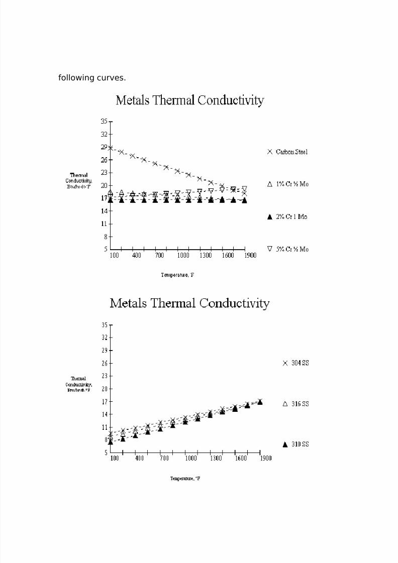
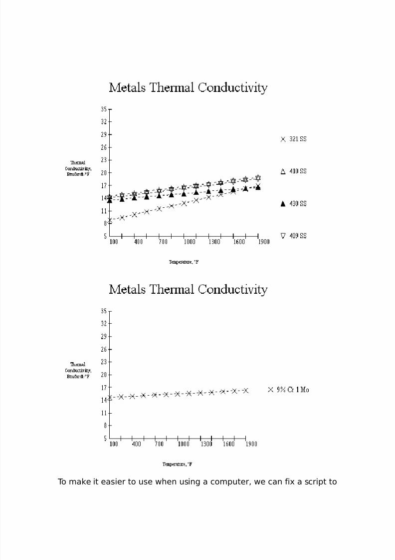
Therma/ Con(uct) )t. Of Meta/*
The thermal conductivity of the tube material and the e'tendedsurface is needed for calculating the heat transfer coefficients. Theconductivity of some of the popular materials can be described by the
8/16/2019 17730094 Fired Heaters
http://slidepdf.com/reader/full/17730094-fired-heaters 71/141
following curves.
8/16/2019 17730094 Fired Heaters
http://slidepdf.com/reader/full/17730094-fired-heaters 72/141
To ma e it easier to use when using a computer% we can fi' a script to
8/16/2019 17730094 Fired Heaters
http://slidepdf.com/reader/full/17730094-fired-heaters 73/141
interpolate the curves for us as follows%
Tu+e 6a// Tem1erature Ca/cu/at)on
The temperature of the tube wall may be calculated using thefollowing e(uations. This method does not ta e co ing into account.
T 7 F/u08( o 9( )8R f):F/u08( o 9( )8#9h ):F/u08( o 92( o "t 38t 92, 8#!3:T f
Chere% T w Tube wall temperature% FFlu' Flu' rate% -tuJhr"ft of bare tubed o )utside tube diameter% ind i Inside tube diameter% int w Tube wall thic ness% inRfi Inside fouling factor% hr"ft "FJ-tuh i Fluid film coefficient% -tuJhr"ft "F
w Thermal conductivity of tube wall% -tuJhr"ft"F
T f -ul process fluid temperature% F
Correct)on To O era// Ra()ant E0change Factor
To predict the radiant heat transfer correctly% it is important to havethe best estimate of the various parameters. The overall e'changefactor used in the previously discussed e(uations% was based oncurves using the gas emissivity and the / wJα / cp . These curvesassumed a tube6blac body7 emissivity of +.>+. ears ago% this was agood appro'imation% and still is today for typical carbon steel tubes.0ome high alloy tubes and tubes that have been coated may haveemissivity properties which may vary dramatically from this +.>+value. However% care should be ta en in assuming that an emissivityvalue for a given material may be the same for that material whenused in a furnace. -ut% it is probably true that many materials do havean emissivity less than +.>+ even in a furnace setting. The curvesbelow were presented by C. 4. 3obo% in a ?anuary ><@% 2hemical
8/16/2019 17730094 Fired Heaters
http://slidepdf.com/reader/full/17730094-fired-heaters 74/141
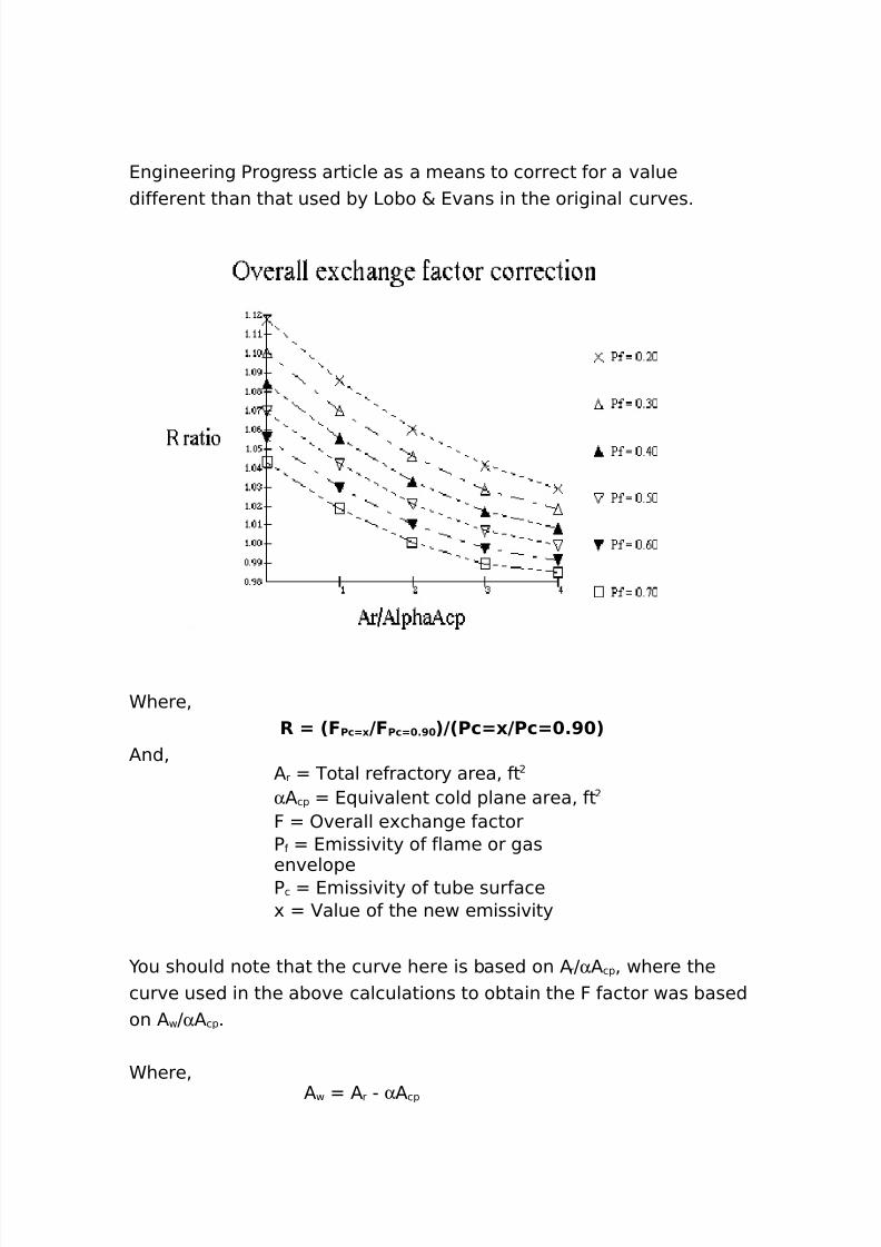
4ngineering Progress article as a means to correct for a valuedifferent than that used by 3obo & 4vans in the original curves.
Chere%R 7 2F Pc70 9FPc7 %> 392Pc709Pc7 %> 3
/nd%/ r Total refractory area% ftα / cp 4(uivalent cold plane area% ftF )verall e'change factorP f 4missivity of flame or gas
envelopePc 4missivity of tube surface' alue of the new emissivity
ou should note that the curve here is based on / rJα / cp % where thecurve used in the above calculations to obtain the F factor was basedon / wJα / cp .
Chere%/ w / r " α / cp
8/16/2019 17730094 Fired Heaters
http://slidepdf.com/reader/full/17730094-fired-heaters 75/141
/ w 4ffective refractory area%ft
Ra()ant Sect)on* 6)th 'a* Tem1erature 'ra()ent*
For furnaces with tall narrow radiant sections or cylindrical heaterswith high 3JD ratios% a #one method may be the appropriate techni(uefor analy#ing the radiant heat transfer. 5any cabin type heaters haveheights two or three% or more times the width of the furnace%particularly when a center bridgewall is installed.
Fre(uently% these furnaces cannot be considered as well"stirred bo'esalthough% to a very great e'tent% this classification is a function of theburner flame characteristics as well as the bo' dimensions. Therehave been numerous studies and papers written on different methodsof ta ing some or all of these factors into account. Ce will use thesimplified 3obo & 4vans radiant transfer procedures as detailed inprevious discussions to analy#e the radiant section in #ones.
/ny method should ta e into account the character and length of theflame and its effect on the ma'imum heat flu'. This is where thehighly theoretical approaches to heater design have a problem. Toassume a hot radiating plane at the base of a cylindrical heater or of arectangular bo' would be to ideali#e the situation. These theoreticalmodels are fine% and they are helpful in setting limits. -ut withoutspecific methods for predetermination of flow patterns from variousburners in various heater designs they wouldnAt necessarily havepractical design purposes. 4ven with specific test furnace data on aburner% the actual operation in the field can and probably would varyfrom the test conditions.
The 3obo & 4vans method can be used in furnace design where thereare wide variations of both flue gas and tube metal temperatures. Itcan be used to estimate the differences in heat flu' along the lengthof vertical tubes within cylindrical or cellular furnaces. it can also beused to analy#e the radiant heat flu'es in the hori#ontal tube #ones.
The basis for this approach is to consider that the any radiant section
8/16/2019 17730094 Fired Heaters
http://slidepdf.com/reader/full/17730094-fired-heaters 76/141
8/16/2019 17730094 Fired Heaters
http://slidepdf.com/reader/full/17730094-fired-heaters 77/141
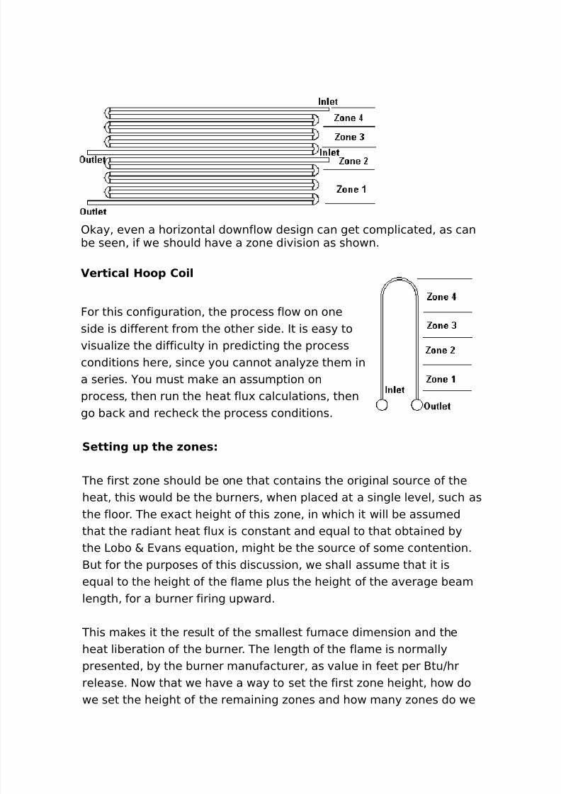
) ay% even a hori#ontal downflow design can get complicated% as canbe seen% if we should have a #one division as shown.
Vert)ca/ Hoo1 Co)/
For this configuration% the process flow on oneside is different from the other side. It is easy tovisuali#e the difficulty in predicting the processconditions here% since you cannot analy#e them ina series. ou must ma e an assumption onprocess% then run the heat flu' calculations% then
go bac and rechec the process conditions.
Sett)ng u1 the Kone*
The first #one should be one that contains the original source of theheat% this would be the burners% when placed at a single level% such asthe floor. The e'act height of this #one% in which it will be assumedthat the radiant heat flu' is constant and e(ual to that obtained bythe 3obo & 4vans e(uation% might be the source of some contention.-ut for the purposes of this discussion% we shall assume that it ise(ual to the height of the flame plus the height of the average beamlength% for a burner firing upward.
This ma es it the result of the smallest furnace dimension and theheat liberation of the burner. The length of the flame is normallypresented% by the burner manufacturer% as value in feet per -tuJhrrelease. $ow that we have a way to set the first #one height% how dowe set the height of the remaining #ones and how many #ones do we
8/16/2019 17730094 Fired Heaters
http://slidepdf.com/reader/full/17730094-fired-heaters 78/141
need It is suggested that you would divide the remaining #ones suchthat they have an e(ual amount of surface in each. In general% thelarger the heater% the more #ones you would divide it into. For moststudies% four to five #ones would be more than enough. -yobservation% if the first #one needs to be fifteen feet and the furnaceradiant section is forty feet high% more than three #ones will probablynot be necessary. In the end% e'perience and test data will be the bestguides.
For the purpose of allowing us to loo at the results of some #one
calculations% we will set up a ?ava0cript below% but we will limit theinput to four #ones to assure that your browser can handle thecalculations without too much delay.
The combustion in fired heaters ta es place in the burner. The typesof burners and how they function are not covered in detail in this
section. The amount of heat released can be easily calculated for agas when we now the composition of the fuel and the heating valuesof the various components. For li(uid fuels% the heating values areobtained by a calorimeter test.From these values and using the standard combustion e(uation% wecan determine the composition of the flue gas. /s an e'ample% thecombustion of methane could be stated L
CH : !O ! """ G CO ! : !H ! O)f course for fuel gases containing many more components andburning in air rather than pure o'ygen% the e(uation gets morecomplicated. Therefore% a tas that in itself is (uite simple% becomes aburden to do by hand% but can be easily accomplished by a simplecomputer program. The heating values normally used in fired heaterdesign are the LHV % lower heating values.
To try some calculations% clic the button below to open anotherwindow to do some fuel combustion calculationsL
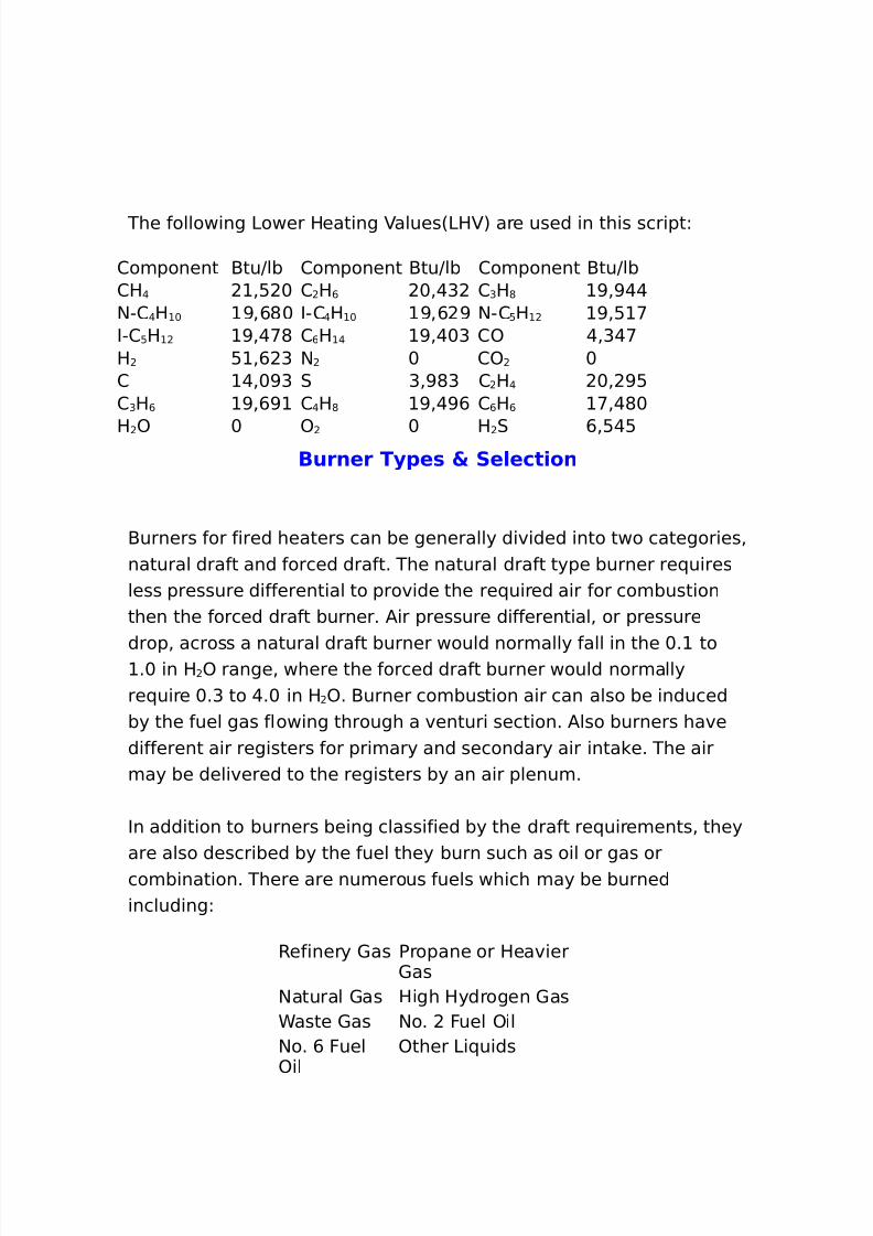
8/16/2019 17730094 Fired Heaters
http://slidepdf.com/reader/full/17730094-fired-heaters 79/141
The following 3ower Heating alues63H 7 are used in this scriptL
2omponent -tuJlb 2omponent -tuJlb 2omponent -tuJlb2H @ %: + 2 H , +%@G 2GH* >%>@@$"2 @H + >%,*+ I"2 @H + >%, > $"2 : H >%: <I"2 : H >%@<* 2, H @ >%@+G 2) @%G@<H : %, G $ + 2) +2 @%+>G 0 G%>*G 2H@ +% >:2 GH , >%,> 2 @H* >%@>, 2 , H, <%@*+
H ) + ) + H 0 ,%:@:Burner T.1e* 5 Se/ect)on
-urners for fired heaters can be generally divided into two categories%natural draft and forced draft. The natural draft type burner re(uiresless pressure differential to provide the re(uired air for combustionthen the forced draft burner. /ir pressure differential% or pressure
drop% across a natural draft burner would normally fall in the +. to.+ in H ) range% where the forced draft burner would normally
re(uire +.G to @.+ in H ). -urner combustion air can also be inducedby the fuel gas flowing through a venturi section. /lso burners havedifferent air registers for primary and secondary air inta e. The airmay be delivered to the registers by an air plenum.
In addition to burners being classified by the draft re(uirements% theyare also described by the fuel they burn such as oil or gas orcombination. There are numerous fuels which may be burnedincludingL
Refinery 1as Propane or Heavier1as
$atural 1as High Hydrogen 1asCaste 1as $o. Fuel )il$o. , Fuel)il
)ther 3i(uids
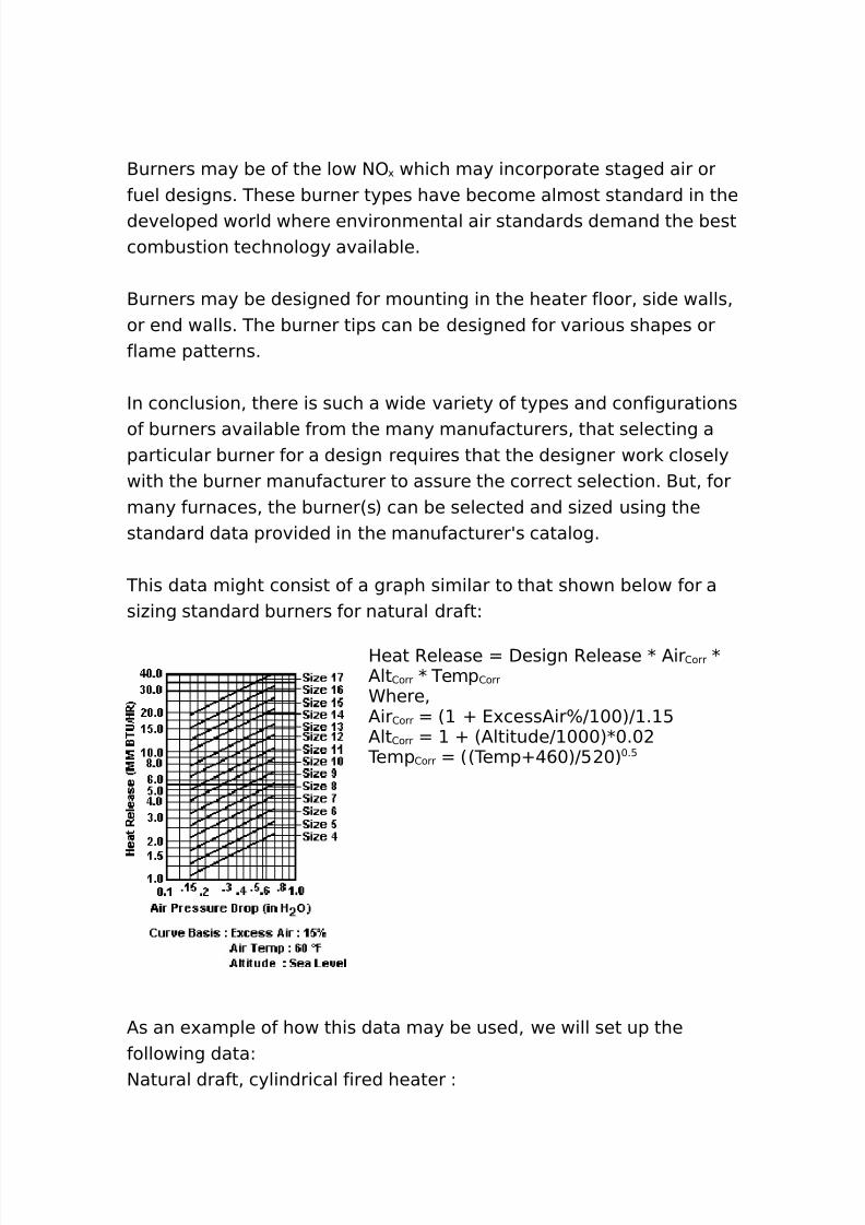
8/16/2019 17730094 Fired Heaters
http://slidepdf.com/reader/full/17730094-fired-heaters 80/141
-urners may be of the low $) ' which may incorporate staged air orfuel designs. These burner types have become almost standard in thedeveloped world where environmental air standards demand the bestcombustion technology available.
-urners may be designed for mounting in the heater floor% side walls%or end walls. The burner tips can be designed for various shapes orflame patterns.
In conclusion% there is such a wide variety of types and configurations
of burners available from the many manufacturers% that selecting aparticular burner for a design re(uires that the designer wor closelywith the burner manufacturer to assure the correct selection. -ut% formany furnaces% the burner6s7 can be selected and si#ed using thestandard data provided in the manufacturerAs catalog.
This data might consist of a graph similar to that shown below for asi#ing standard burners for natural draftL
Heat Release Design Release K /ir 2orr K/lt 2orr K Temp 2orr
Chere%/ir 2orr 6 O 4'cess/irBJ ++7J . :/lt 2orr O 6/ltitudeJ +++7K+.+
Temp 2orr 66TempO@,+7J: +7 +.:
/s an e'ample of how this data may be used% we will set up thefollowing dataL$atural draft% cylindrical fired heater L
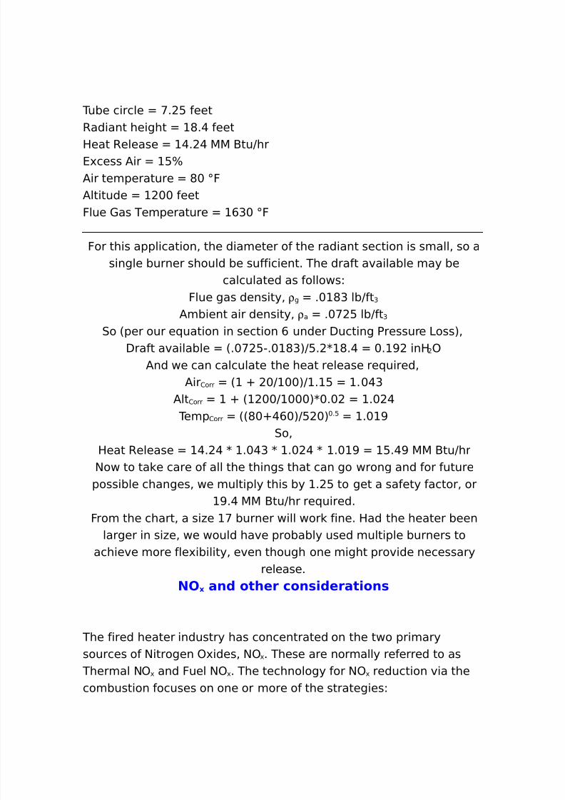
8/16/2019 17730094 Fired Heaters
http://slidepdf.com/reader/full/17730094-fired-heaters 81/141
Tube circle <. : feetRadiant height *.@ feetHeat Release @. @ 55 -tuJhr4'cess /ir :B/ir temperature *+ ;F/ltitude ++ feetFlue 1as Temperature ,G+ ;F
For this application% the diameter of the radiant section is small% so asingle burner should be sufficient. The draft available may be
calculated as followsLFlue gas density% ρ g .+ *G lbJft G
/mbient air density% ρ a .+< : lbJft G
0o 6per our e(uation in section , under Ducting Pressure 3oss7%Draft available 6.+< :".+ *G7J:. K *.@ +. > inH )
/nd we can calculate the heat release re(uired%/ir 2orr 6 O +J ++7J . : .+@G
/lt 2orr O 6 ++J +++7K+.+ .+ @
Temp 2orr 66*+O@,+7J: +7+.:
.+ >0o%
Heat Release @. @ K .+@G K .+ @ K .+ > :.@> 55 -tuJhr$ow to ta e care of all the things that can go wrong and for future
possible changes% we multiply this by . : to get a safety factor% or>.@ 55 -tuJhr re(uired.
From the chart% a si#e < burner will wor fine. Had the heater beenlarger in si#e% we would have probably used multiple burners to
achieve more fle'ibility% even though one might provide necessaryrelease.
NO 0 an( other con*)(erat)on*
The fired heater industry has concentrated on the two primarysources of $itrogen )'ides% $) ' . These are normally referred to as
Thermal $) ' and Fuel $) ' . The technology for $) ' reduction via thecombustion focuses on one or more of the strategiesL
8/16/2019 17730094 Fired Heaters
http://slidepdf.com/reader/full/17730094-fired-heaters 82/141
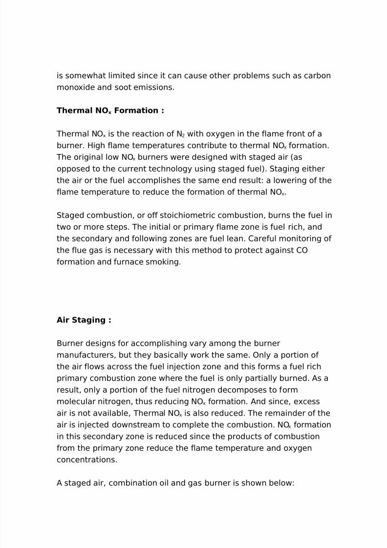
8/16/2019 17730094 Fired Heaters
http://slidepdf.com/reader/full/17730094-fired-heaters 83/141
is somewhat limited since it can cause other problems such as carbonmono'ide and soot emissions.
Therma/ NO 0 Format)on
Thermal $) ' is the reaction of $ with o'ygen in the flame front of aburner. High flame temperatures contribute to thermal $) ' formation.
The original low $) ' burners were designed with staged air 6asopposed to the current technology using staged fuel7. 0taging eitherthe air or the fuel accomplishes the same end resultL a lowering of the
flame temperature to reduce the formation of thermal $) ' .
0taged combustion% or off stoichiometric combustion% burns the fuel intwo or more steps. The initial or primary flame #one is fuel rich% andthe secondary and following #ones are fuel lean. 2areful monitoring ofthe flue gas is necessary with this method to protect against 2)formation and furnace smo ing.
A)r Stag)ng
-urner designs for accomplishing vary among the burnermanufacturers% but they basically wor the same. )nly a portion ofthe air flows across the fuel in!ection #one and this forms a fuel richprimary combustion #one where the fuel is only partially burned. /s aresult% only a portion of the fuel nitrogen decomposes to formmolecular nitrogen% thus reducing $) ' formation. /nd since% e'cessair is not available% Thermal $) ' is also reduced. The remainder of theair is in!ected downstream to complete the combustion. $) ' formationin this secondary #one is reduced since the products of combustionfrom the primary #one reduce the flame temperature and o'ygenconcentrations.
/ staged air% combination oil and gas burner is shown belowL
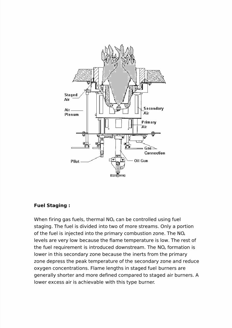
8/16/2019 17730094 Fired Heaters
http://slidepdf.com/reader/full/17730094-fired-heaters 84/141
Fue/ Stag)ng
Chen firing gas fuels% thermal $) ' can be controlled using fuelstaging. The fuel is divided into two of more streams. )nly a portionof the fuel is in!ected into the primary combustion #one. The $) '
levels are very low because the flame temperature is low. The rest ofthe fuel re(uirement is introduced downstream. The $) ' formation islower in this secondary #one because the inerts from the primary#one depress the pea temperature of the secondary #one and reduceo'ygen concentrations. Flame lengths in staged fuel burners aregenerally shorter and more defined compared to staged air burners. /lower e'cess air is achievable with this type burner.
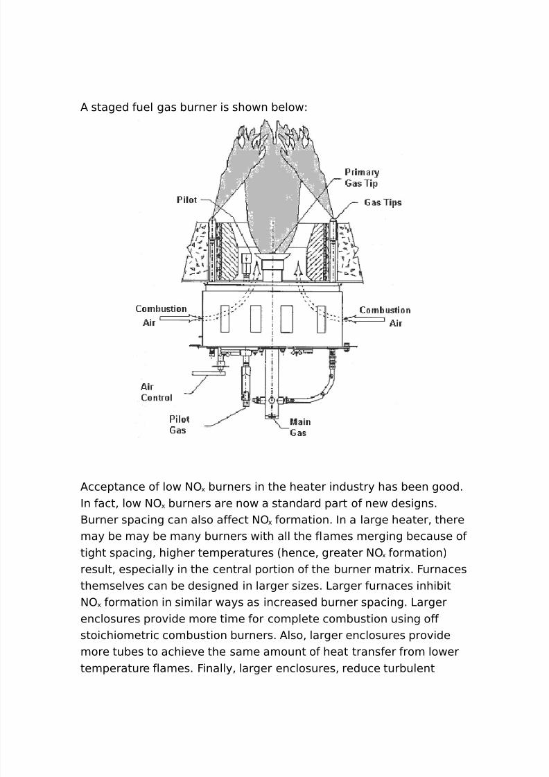
8/16/2019 17730094 Fired Heaters
http://slidepdf.com/reader/full/17730094-fired-heaters 85/141
/ staged fuel gas burner is shown belowL
/cceptance of low $) ' burners in the heater industry has been good.In fact% low $) ' burners are now a standard part of new designs.-urner spacing can also affect $) ' formation. In a large heater% theremay be may be many burners with all the flames merging because oftight spacing% higher temperatures 6hence% greater $) ' formation7result% especially in the central portion of the burner matri'. Furnacesthemselves can be designed in larger si#es. 3arger furnaces inhibit$) ' formation in similar ways as increased burner spacing. 3argerenclosures provide more time for complete combustion using offstoichiometric combustion burners. /lso% larger enclosures providemore tubes to achieve the same amount of heat transfer from lowertemperature flames. Finally% larger enclosures% reduce turbulent
8/16/2019 17730094 Fired Heaters
http://slidepdf.com/reader/full/17730094-fired-heaters 86/141
mi'ing of the fuel and air% which also inhibits $) ' formation6particularly fuel $) ' 7.
Fue/ NO 0
Fuel $) ' is $) ' formed by nitrogen atoms that are chemically boundin the fuel. 3i(uid fuels almost always contain some nitrogen% and as arule% li(uid fuels ma e more $) ' than burning gases. 1enerally singlenitrogen atoms are the most reactive. /mines and ammonia in thefuel contribute greatly to fuel $) ' formation.
F/ue ga* rec)rcu/at)on
Flue gas recirculation is simply the rerouting of some of the flue gasbac to the furnace. The (uenching effect from the 2) rich flue gaslowers the ) concentration in the combustion #one% as well as theadiabatic flame temperature. 8p to +B flue gas recirculation is veryeffective. In addition to re(uiring large ducts% fans% and dampers%
additional controls will be re(uired. The additional gas flow throughthe firebo' and flues must be ta en into account in the furnacedesign.
Steam In ect)on
Cater in!ection 6or steam in!ection7 can be an effective means ofreducing flame temperatures% thus reducing thermal $) ' . This methodin!ects steam into the flame #one to reduce flame temperatures.0team in!ection into the fuel gas at rates up to G+B by weight havebeen shown to be (uite effective.
/bove% we have discussed the ways to modify the combustion processto prevent the formation of $) ' . -ut% post flame $) ' control may alsobe used. The more common post flame treatment is use of 0elective2atalytic Reduction 602R7 to convert the $) ' to $ .
Se/ect) e Cata/.t)c Re(uct)on
8/16/2019 17730094 Fired Heaters
http://slidepdf.com/reader/full/17730094-fired-heaters 87/141
Postflame treatment processes add a reducing agent to thecombustion gas stream to ta e o'ygen away from $). For largeheaters ammonia is used as the reducing agent. The desired reactionis
@NO : NH $ 7 =N ! : @H ! O
This re(uires JG ammonia molecules for each molecule of $).However% there is always some o'ygen present% which leads to
reactions li e the followingL
NO : NH $ : O ! 7 N ! : @H ! O
In this reaction one ammonia molecule is re(uired for each moleculeof $). $) is reduced by
!NO ! : NH $ : O ! 7 $N ! : @H ! O
These reactions can be carried out over a #eolite catalyst at <++ o to*++ ;F. This catalytic process has been employed on a large scale andgives up to *:B reduction in $) .
T)tan)um an( Vana()um Cata/.*t*
The first successful commercial $) 02R system was built by Hitachiosen in ><:. 0ince then% the technology has become well
established world wide. The catalyst used is a honeycomb shapedmetal or ceramic plate with active sites made up of a mi'ture oftitanium and vanadium o'ides. The catalysts are selective to optimi#e$) activity and minimi#e 0) o'idation. The honeycomb shape isdesirable to minimi#e plugging if particulates are present. The besttemperature range for 02R catalyst activity and selectivity is from
8/16/2019 17730094 Fired Heaters
http://slidepdf.com/reader/full/17730094-fired-heaters 88/141
<++ ; to *++ ;F. /mmonia is in!ected downstream from thecombustion #one and upstream of the catalyst.
In process heaters the catalyst undergoes slow deactivation over along period of time. The thic ness and hence the space velocity of thehoneycomb bloc s is typically specified for a three year life. /s theactivity of the catalyst decreases% the amount of e'cess ammoniare(uired for the desired conversion increases. 5a'imum allowableammonia 9slip9 is specified when the catalyst is purchased. /mmoniaslip of + ppm is typical. The catalyst is manufactured in bloc s that
are held in place in the stac gas ductwor by a stainless steel T"bargrid.
The ammonia is in!ected upstream of the catalyst grid through its ownin!ection grid in a turbulent #one. /nhydrous or a(ueous ammonia canbe used% depending on the policies of the plant where the system is tobe installed. In the case of a(ueous ammonia% the material can eitherbe vapori#ed first and in!ected as a vapor% or in some duct
configurations% it can sprayed in through an atomi#ing spray no##le.
02R catalyst substrate is recyclable and can be regenerated by themanufacturer if it has not been deformed or damaged by heat. 5ostoften a spare charge is ept on hand for changeout during routineturnarounds and the spent material is sent in for regeneration. Thereis about a G+B cost savings in reusing the substrate over a newpurchase and it eliminates catalyst disposal cost concerns.
-elow is a s etch of a direct fired heater system utili#ing an 02R unitand /ir Preheat system.
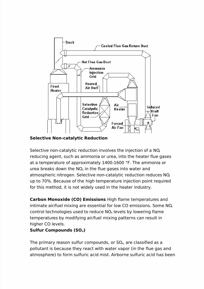
8/16/2019 17730094 Fired Heaters
http://slidepdf.com/reader/full/17730094-fired-heaters 89/141
8/16/2019 17730094 Fired Heaters
http://slidepdf.com/reader/full/17730094-fired-heaters 90/141
found in fog% smog% acid rain% and snow. 0ulfuric acid has also beenfound in la es% rivers% and soil. The acid is e'tremely corrosive andharmful to the environment.
The combustion of fuels containing sulfur results in pollutantsoccurring in the forms of 0) 6sulfur dio'ide7 and 0) G 6sulfur trio'ide7%together referred to as 0) ' 6sulfur o'ides7. The level of 0) ' emitteddepends directly on the sulfur content of the fuel. The level of 0) '
emissions is not dependent on boiler si#e or burner design. Typically%about >:B of the sulfur in the fuel will be emitted as 0) % ":B as
0) G% and "GB as sulfate particulate. 0ulfate particulate is notconsidered part of the total 0) ' emissions.
Historically% 0) ' pollution has been controlled by either dispersion orreduction. Dispersion involves the utili#ation of a tall stac % whichenables the release of pollutants high above the ground and over anysurrounding buildings% mountains% or hills% in order to limit groundlevel 0) ' emissions. Today% dispersion alone is not enough to meet
more stringent 0) ' emission re(uirementsU reduction methods mustalso be employed.
5ethods of 0) ' reduction in fired heaters consits of switching to lowsulfur fuel. Heater design primarily re(uires ta ing the sulfur intoaccount in the convection section. 0ee section :% page , for morediscussion on the acid dew point of flue gases.
Car+on Mono0)(e 2CO3
2arbon mono'ide is a pollutant that is readily absorbed in the bodyand can impair the o'ygen"carrying capacity of the hemoglobin.Impairment of the bodyAs hemoglobin results in less o'ygen to thebrain% heart% and tissues. 4ven short"term over e'posure to carbonmono'ide can be critical% or fatal% to people with heart and lungdiseases. It may also cause headaches and di##iness in healthypeople.
8/16/2019 17730094 Fired Heaters
http://slidepdf.com/reader/full/17730094-fired-heaters 91/141
During combustion% carbon in the fuel o'idi#es through a series ofreactions to form carbon dio'ide 62) 7. However% ++ percentconversion of carbon to 2) is rarely achieved in practice and somecarbon only o'idi#es to the intermediate step% carbon mono'ide.
)lder heaters generally have higher levels of 2) than new e(uipmentbecause 2) has only recently become a concern and older burnerswere not designed to achieve low 2) levels. In todayAs e(uipment%high levels of carbon mono'ide emissions primarily result fromincomplete combustion due to poor burner design or firing conditions
6for e'ample% an improper air"to"fuel ratio7 or possibly a lea y furnace. Through proper burner maintenance% inspections% operation% or byupgrading e(uipment or utili#ing an o'ygen control pac age% theformation of carbon mono'ide can be controlled at an acceptablelevel.
Part)cu/ate Matter 2PM3
4missions of particulate matter 6P57 from combustion sources consistof many different types of compounds% including nitrates% sulfates%carbons% o'ides% and any uncombusted elements in the fuel.Particulate pollutants can be corrosive% to'ic to plants and animals%and harmful to humans.
Particulate matter emissions generally are classified into twocategories% P5 and P5 +. P5 + is a particulate matter with adiameter less than + microns. /ll particulate matter can pose ahealth problem. However% the greatest concern is with P5 +% becauseof its ability to bypass the bodyAs natural filtering system.
P5 emissions are primarily dependent on the grade of fuel fired in theboiler. 1enerally% P5 levels from natural gas are significantly lowerthan those of oils. Distillate oils result in much lower particulateemissions than residual oils.
8/16/2019 17730094 Fired Heaters
http://slidepdf.com/reader/full/17730094-fired-heaters 92/141
Chen burning heavy oils% particulate levels mainly depend on fourfuel constituentsL sulfur% ash% carbon residue% and asphalenes. Theseconstituents e'ist in fuel oils% particularly residual oils% and have ama!or effect on particulate emissions. -y nowing the fuel constituentlevels% the particulate emissions for the oil can be estimated.
For most heater applications% the most effective method is to utili#eclean fuels. The emission levels of particulate matter can be loweredby switching from a residual to a distillate oil or by switching from adistillate oil to a natural gas. /dditionally% through proper burner set"
up% ad!ustment and maintenance% particulate emissions can beminimi#ed% but not to the e'tent accomplished by switching fuels.
Vo/at)/e Organ)c Com1oun(* 2VOC*39H&DROCARBONS 2HC3
olatile organic compounds% or )2s% are compounds containingcombinations of carbon% hydrogen% and sometimes o'ygen. )2svapori#e easily once emitted into the air and are of concern because
of their role in ground level o#one formation. In reference to heaterperformance% they are often referred to as hydrocarbons andgenerally are divided into two categories V methane and non"methane. Formation of )2s in fired heaters primarily result frompoor or incomplete combustion due to improper burner set"up andad!ustment. To control )2 emissions from fired heaters% no au'iliarye(uipment is neededU properly maintaining the burnerJcontrolpac age will eep )2 emissions at a minimum. Proper maintenanceincludes eeping the airJfuel ratio at the manufacturerAs specifiedsetting% having the proper air and fuel pressures at the burner% andmaintaining the atomi#ing air pressure on oil burners at the correctlevels. /n improperly maintained controlJburner pac age can result in
)2 levels over ++ times the normal levels.
Correct)ng Em)**)on* To $ O0.gen 2#= E0ce** A)r3
The following e(uation shows how to correct emission readings to GBo'ygen 6 :B e'cess air7. -ecause heaters donAt always operate at GB
8/16/2019 17730094 Fired Heaters
http://slidepdf.com/reader/full/17730094-fired-heaters 93/141
o'ygen% it is necessary to convert ppm values measured at variouse'cess air levels to GB o'ygen for comparison and regulationcompliance purposes. To correct emission levels to GB o'ygen thatare referenced to e'cess air levels other than GB% use the followinge(uation.
11m $ 7 22!#"$392!#"O ! 33811m Em)*
4'ampleL Chat is the $) ' level corrected to GB o'ygen for ameasured level of G, ppm at *.GB o'ygen
11m $ 7 22!#"$392!#"?%$338$@ 7 =# 11m
Pur1o*e Of E0ce** A)r
Perfect combustion is achieved when all the fuel is burned using onlythe theoretical amount of air. Perfect combustion cannot be achievedin a fired heater. 2omplete combustion is achieved when all the fuel isburned using the minimal amount of air above the theoretical amountof air needed to burn the fuel. Cith complete combustion% the fuel isburned at the highest combustion efficiency. Incomplete combustionoccurs when all the fuel is not burned% which results in the formationof soot and smo e.
)'ygen for combustion is obtained from the atmosphere% which isabout B o'ygen by volume or GB by weight. /bout +++ cubicfeet of air is re(uired to burn one gallon of fuel oil at *+B efficiency atsea level. /bout : cubic feet of air is re(uired to burn one cubic footof natural gas at <:B at sea level. 5ost of the <>B of air that is noto'ygen is nitrogen% with traces of other elements. $itrogen is inert atordinary flame temperature and forms few compounds as the result ofcombustion. $itrogen is an unwanted 9parasite9 that must be
8/16/2019 17730094 Fired Heaters
http://slidepdf.com/reader/full/17730094-fired-heaters 94/141
accepted in order to obtain the o'ygen. It contributes nothing tocombustion% it increases the volume of combustion products to bevented% it steals heat from the reaction and now creates a growingenvironmental problem as well.
/ir re(uired in combustion is classified asL
Pr)mar. A)r
Primary air controls the rate of combustion% which determines the
amount of fuel that can be burned.
Secon(ar. A)r
0econdary air controls combustion efficiency by controlling howcompletely the fuel is burned.
E0ce** A)r
4'cess air is air supplied to the burner that e'ceeds the theoreticalamount needed to burn the fuel.
2ombustion air re(uirements are based on the composition of the fuelused and the design of the burner. Fuels commonly used containnitrogen% ash% o'ygen% sulfur% carbon and hydrogen. Chen a fuel has alarge volume of nitrogen that must be accepted along with thedesired o'ygen% more e'cess air should be provided. That e'cess airhas a chilling effect on the flame. 0ome fuel particles fail to combinewith o'ygen and pass out of the stac unburned.
Cater vapor is a by"product of burning hydrogen. It too subtracts heatfrom the flame and becomes steam at flue gas temperature% passingout of the stac as vapor mi'ed with the combustion products.
8/16/2019 17730094 Fired Heaters
http://slidepdf.com/reader/full/17730094-fired-heaters 95/141
$atural gas contains more hydrogen and less carbon per unit of heatcontent than oil and conse(uently its combustion produces a greatdeal more water vapor which withdraws a greater amount of heatfrom the flame. Therefore gas efficiency is always slightly less than oilefficiency.
/ir re(uirements for combustion are generally e'pressed in cubic feetof air per gallon of oil or per cubic foot of gas for conveniencebecause fans% ducts and other air moving devices are rated in cubicfeet per minute or cubic feet per hour. The FuelJ/ir Ratio for
combustion is actually a weight ratio based on the re(uired weight ofo'ygen for a given weight of fuel.
The good news about e'cess air is that it provides a measure ofsafety. The bad news is that it wastes fuel. The less e'cess air usedresults in the least amount of 9waste9.
Preheate( Com+u*t)on A)r
9Technology is now available to increase efficiencies to > percentand better.9 I wrote those words in ><> for a paper presented to the5id" ear /PI meeting in 5ay of ><>. The words are still true today.
The single% most significant obstacle to overcome in this application ishigh flue gas dew points versus percent sulphur in both oil and gasfuels. In the years since ><>% the problem with flue gas dew pointhas been offset to some degree by the use of cleaner fuels. Howeverin some applications% it is still a concern. The calculation of flue gasdew point temperature when sulphur is present is discussed on page, of this section.
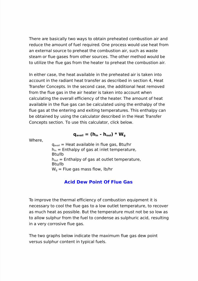
8/16/2019 17730094 Fired Heaters
http://slidepdf.com/reader/full/17730094-fired-heaters 96/141
There are basically two ways to obtain preheated combustion air andreduce the amount of fuel re(uired. )ne process would use heat froman e'ternal source to preheat the combustion air% such as wastesteam or flue gases from other sources. The other method would beto utili#e the flue gas from the heater to preheat the combustion air.
In either case% the heat available in the preheated air is ta en intoaccount in the radiant heat transfer as described in section @% Heat
Transfer 2oncepts. In the second case% the additional heat removedfrom the flue gas in the air heater is ta en into account when
calculating the overall efficiency of the heater. The amount of heatavailable in the flue gas can be calculated using the enthalpy of theflue gas at the entering and e'iting temperatures. This enthalpy canbe obtained by using the calculator described in the Heat Transfer2oncepts section. To use this calculator% clic below.
a a)/ 7 2h )n " h out 3 8 6 g
Chere%( avail Heat available in flue gas% -tuJhrh in 4nthalpy of gas at inlet temperature%-tuJlbh out 4nthalpy of gas at outlet temperature%-tuJlbC g Flue gas mass flow% lbJhr
Ac)( De Po)nt Of F/ue 'a*
To improve the thermal efficiency of combustion e(uipment it isnecessary to cool the flue gas to a low outlet temperature% to recoveras much heat as possible. -ut the temperature must not be so low asto allow sulphur from the fuel to condense as sulphuric acid% resultingin a very corrosive flue gas.
The two graphs below indicate the ma'imum flue gas dew pointversus sulphur content in typical fuels.
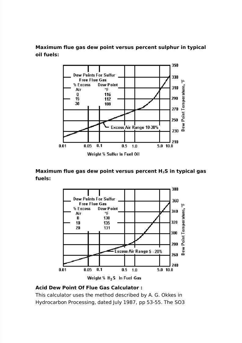
8/16/2019 17730094 Fired Heaters
http://slidepdf.com/reader/full/17730094-fired-heaters 97/141
Ma0)mum f/ue ga* (e 1o)nt er*u* 1ercent *u/1hur )n t.1)ca/o)/ fue/*
Ma0)mum f/ue ga* (e 1o)nt er*u* 1ercent H ! S )n t.1)ca/ ga*
fue/*
Ac)( De Po)nt Of F/ue 'a* Ca/cu/ator This calculator uses the method described by /. 1. ) es inHydrocarbon Processing% dated ?uly >*<% pp :G"::. The 0)G
8/16/2019 17730094 Fired Heaters
http://slidepdf.com/reader/full/17730094-fired-heaters 98/141
conversion from 0) % if calculated% is assumed to be set bye(uilibrium at +++ ;2. The flue gas is assumed to be at atmosphericpressure. / deviation of ++mm H ) will result in a +.@ ;2 error in thepredicted dew point.Flue 1as 2omposition% mole B $itrogen
)'ygen 2arbon Dio'ide Cater /rgon 0ulphur Dio'ide
0ulphur Trio'ide6Input 2 to calculate7
F/ame Tem1erature Ca/cu/ator
Ba*e( on art)c/e +. Car/ A% Vanc)n)4 )n Chem)ca/ Eng)neer)ng4March !!4 #>?!
Here a simple heat balance serves as the basis for calculating theflame temperature. The increase in enthalpy between the unburnedand burned mi'tures is set e(ual to the heat produced by combustion.
8p to a flame temperature of about %:++ ;F% the burned mi'turegenerally includes such ordinary gases as 2) % $ % 0) % H)% andresidual ) 6from e'cess air7. /t higher temperatures% 2) appreciablydissociates to 2) and ) U H ) to ) and )H "U ) to ) " U H to H OU $ to$ "G and $) 6produced by $ and ) 7 to $ "G and ) " . These dissociationreactions absorb an enormous amount of energy 6heat7% substantiallylowering the flame temperature being calculated.
Heat Ba/ance
The heat balance is calculated as followsL /t constant pressure% theheat% W% re(uired to bring the temperature of one pound of gas fromtemperature + to temperature t isL
8/16/2019 17730094 Fired Heaters
http://slidepdf.com/reader/full/17730094-fired-heaters 99/141
7 f 0 t c 1 ( t 6 7
The variation of c p with temperature can be appro'imated by apolynomial% having the obvious advantage of being integrated easily.8sing a third"degree polynomial% we can write c p asL
c 1 7 a : bt : ct ! : dt $ 6 7
where% a, b, c, and d are constants that depend on the nature of the
gas. 4(uation 6 7 thus becomesL
7 f 0 t 2a : bt : ct ! : dt $ 3( t 6G7
IntegratingL
7 2 a : bt 9! : ct ! 9$ : dt $ 9 3t 6@7
It is customary to call the parenthetic term in 4(uation 6@7 the meanspecific heatL
c 1m 7 a : bt 9! : ct ! 9$ : dt $ 9 6:7
0o 4(uation @ can be written asL
c 1m t 7 at : bt ! 9! : ct $ 9$ : dt 9 6,7
-y ta ing mean specific heats instead of the true ones% we candispense with integration of 4(uation 6 7. Tabulations are available ofc p and c pm for many gases 6not considering dissociation7.
D)**oc)at)on
High"temperature dissociation of gases is a reaction that reachese(uilibrium. 4(uilibrium depends on composition% total pressure and
8/16/2019 17730094 Fired Heaters
http://slidepdf.com/reader/full/17730094-fired-heaters 100/141
temperature. The degree of approach to e(uilibrium is also time"dependent. Tabulations of e(uilibrium constants for commondissociation reactions are available.
Hand calculation of the effect of dissociation on the flametemperature is e'tremely tedious% owing to the large number ofreactions involved. For e'ample% in the combustion of acetylene withair% one must solve a set of ten e(uations for ten un nown partialpressures. Here% polynomial e'pressions for the e(uilibrium constantscan be used X,Y% although with much difficulty.
?usti X<Y gives values of the ratio nU/t 6see nomenclature7 for severaldissociation reactions at various temperatures at atm. /ssuming alinear variation of the dissociation effects on temperature with thepartial pressure of each dissociating gas% the ratio nU/t can be used tomodify the mean specific heat of gases.
The figure illustrates the variation of c pm with temperature% for several
gases. This variation ta es into account the above approach% whichincludes the effect of dissociation. The profiles of c pm in this figure aresomewhat different from those calculated by applying the modifiers of
?usti. Those in the figure use more"recent thermal data and bettervalues of calculated flame temperaturesX*Y.
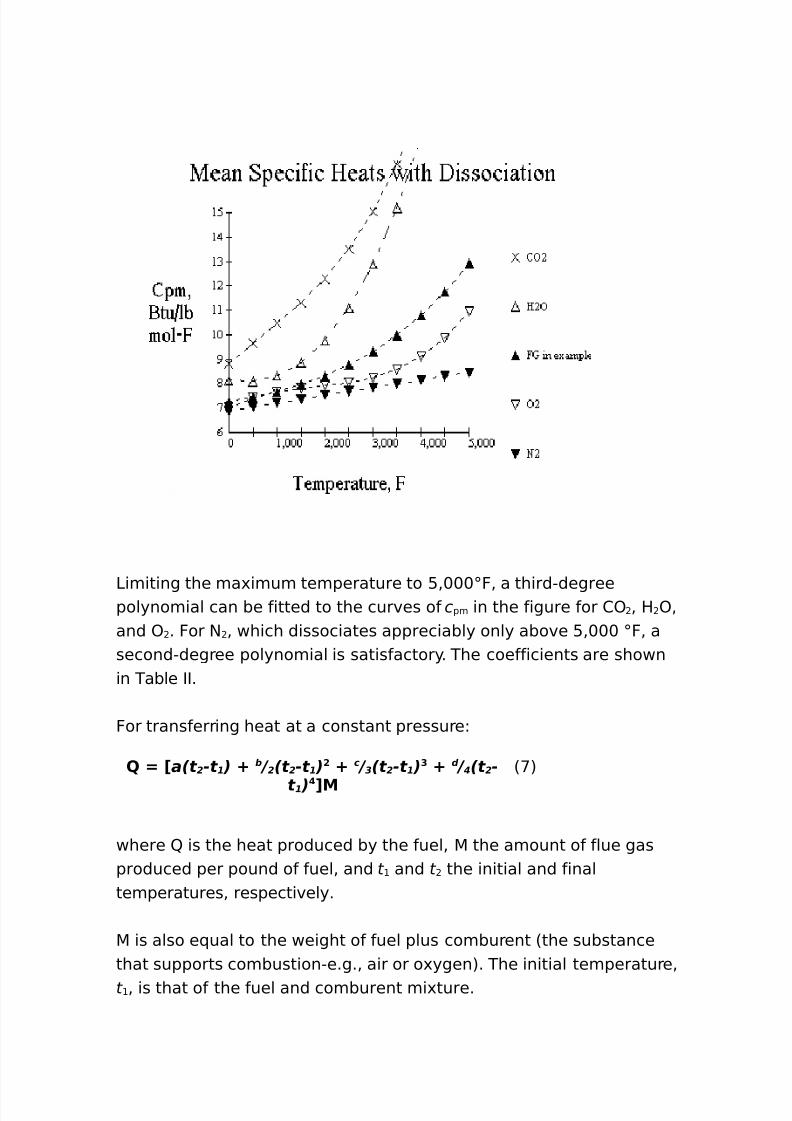
8/16/2019 17730094 Fired Heaters
http://slidepdf.com/reader/full/17730094-fired-heaters 101/141
3imiting the ma'imum temperature to :%+++;F% a third"degreepolynomial can be fitted to the curves of c pm in the figure for 2) % H)%and ) . For $ % which dissociates appreciably only above :%+++ ;F% asecond"degree polynomial is satisfactory. The coefficients are shownin Table II.
For transferring heat at a constant pressureL
7 a(t 2 -t 1 ) : b / 2 (t 2 -t 1 ) ! : c / 3 (t 2 -t 1 ) $ : d / 4 (t 2 -
t 1 ) M
6<7
where W is the heat produced by the fuel% 5 the amount of flue gasproduced per pound of fuel% and t and t the initial and finaltemperatures% respectively.
5 is also e(ual to the weight of fuel plus comburent 6the substancethat supports combustion"e.g.% air or o'ygen7. The initial temperature%t % is that of the fuel and comburent mi'ture.
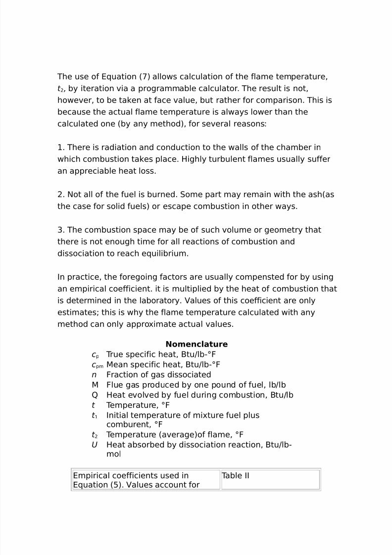
8/16/2019 17730094 Fired Heaters
http://slidepdf.com/reader/full/17730094-fired-heaters 102/141
The use of 4(uation 6<7 allows calculation of the flame temperature%t % by iteration via a programmable calculator. The result is not%however% to be ta en at face value% but rather for comparison. This isbecause the actual flame temperature is always lower than thecalculated one 6by any method7% for several reasonsL
. There is radiation and conduction to the walls of the chamber inwhich combustion ta es place. Highly turbulent flames usually sufferan appreciable heat loss.
. $ot all of the fuel is burned. 0ome part may remain with the ash6asthe case for solid fuels7 or escape combustion in other ways.
G. The combustion space may be of such volume or geometry thatthere is not enough time for all reactions of combustion anddissociation to reach e(uilibrium.
In practice% the foregoing factors are usually compensted for by using
an empirical coefficient. it is multiplied by the heat of combustion thatis determined in the laboratory. alues of this coefficient are onlyestimatesU this is why the flame temperature calculated with anymethod can only appro'imate actual values.
Nomenc/aturec p True specific heat% -tuJlb";Fc pm 5ean specific heat% -tuJlb";Fn Fraction of gas dissociated
5 Flue gas produced by one pound of fuel% lbJlbW Heat evolved by fuel during combustion% -tuJlbt Temperature% ;Ft Initial temperature of mi'ture fuel plus
comburent% ;Ft Temperature 6average7of flame% ;FU Heat absorbed by dissociation reaction% -tuJlb"
mol
4mpirical coefficients used in
4(uation 6:7. alues account for
Table II
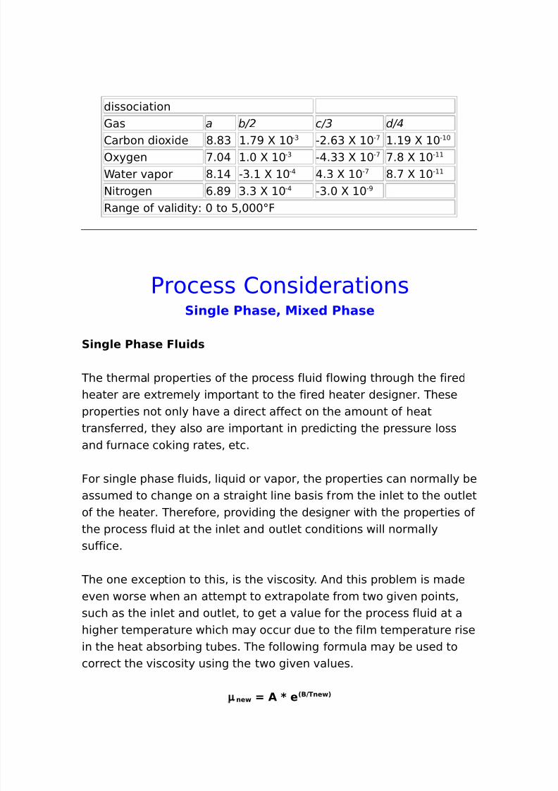
8/16/2019 17730094 Fired Heaters
http://slidepdf.com/reader/full/17730094-fired-heaters 103/141
dissociation1as a b/2 c/3 d/4
2arbon dio'ide *.*G .<> S + "G " .,G S + "< . > S + " +
)'ygen <.+@ .+ S + "G "@.GG S + "< <.* S + "
Cater vapor *. @ "G. S + "@ @.G S + "< *.< S + "
$itrogen ,.*> G.G S + "@ "G.+ S + ">
Range of validityL + to :%+++;F
Process 2onsiderationsS)ng/e Pha*e4 M)0e( Pha*e
S)ng/e Pha*e F/u)(*
The thermal properties of the process fluid flowing through the firedheater are e'tremely important to the fired heater designer. These
properties not only have a direct affect on the amount of heattransferred% they also are important in predicting the pressure lossand furnace co ing rates% etc.
For single phase fluids% li(uid or vapor% the properties can normally beassumed to change on a straight line basis from the inlet to the outletof the heater. Therefore% providing the designer with the properties ofthe process fluid at the inlet and outlet conditions will normallysuffice.
The one e'ception to this% is the viscosity. /nd this problem is madeeven worse when an attempt to e'trapolate from two given points%such as the inlet and outlet% to get a value for the process fluid at ahigher temperature which may occur due to the film temperature risein the heat absorbing tubes. The following formula may be used tocorrect the viscosity using the two given values.
µ ne 7 A 8 e 2B9Tne 3
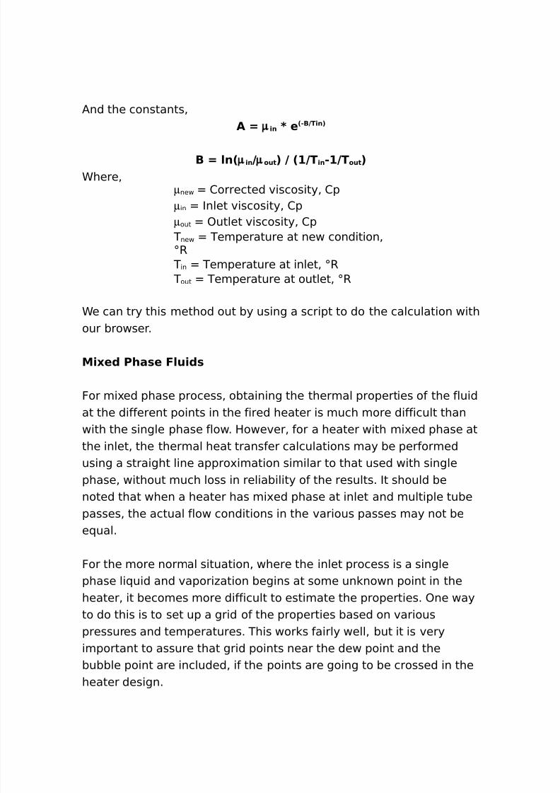
8/16/2019 17730094 Fired Heaters
http://slidepdf.com/reader/full/17730094-fired-heaters 104/141
/nd the constants%A 7 µ )n 8 e 2"B9T)n3
B 7 /n2 µ )n 9µ out 3 9 2#9T )n "#9T out 3Chere%
µnew 2orrected viscosity% 2pµin Inlet viscosity% 2pµout )utlet viscosity% 2p
T new Temperature at new condition%;R
T in Temperature at inlet% ;R
T out Temperature at outlet% ;R
Ce can try this method out by using a script to do the calculation withour browser.
M)0e( Pha*e F/u)(*
For mi'ed phase process% obtaining the thermal properties of the fluid
at the different points in the fired heater is much more difficult thanwith the single phase flow. However% for a heater with mi'ed phase atthe inlet% the thermal heat transfer calculations may be performedusing a straight line appro'imation similar to that used with singlephase% without much loss in reliability of the results. It should benoted that when a heater has mi'ed phase at inlet and multiple tubepasses% the actual flow conditions in the various passes may not bee(ual.
For the more normal situation% where the inlet process is a singlephase li(uid and vapori#ation begins at some un nown point in theheater% it becomes more difficult to estimate the properties. )ne wayto do this is to set up a grid of the properties based on variouspressures and temperatures. This wor s fairly well% but it is veryimportant to assure that grid points near the dew point and thebubble point are included% if the points are going to be crossed in theheater design.
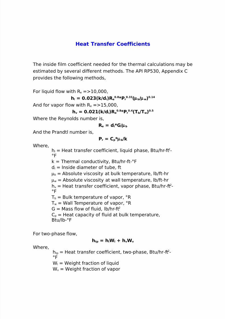
8/16/2019 17730094 Fired Heaters
http://slidepdf.com/reader/full/17730094-fired-heaters 105/141
8/16/2019 17730094 Fired Heaters
http://slidepdf.com/reader/full/17730094-fired-heaters 106/141
The following script will allow us to try these formulas out using ourbrowser.
It should be stressed at this time% that there are many ways tocalculate the inside heat transfer coefficient% and a lot of care should
be ta en in the procedure selected for use in heater design. )thermethods% such as HTRI% 5a'well% Dittus"-oel#er% or others may be
more appropriate for a particular heater design.Intu+e Pre**ure Dro1
The intube pressure drop may be calculated by any number ofmethods available today% but the following procedures should givesufficient results for heater design. The pressure loss in heater tubesand fittings is normally calculated by first converting the fittings to ane(uivalent length of pipe. Then the average properties for a segmentof piping and fittings can be used to calculate a pressure drop per foot
to apply to the overall e(uivalent length. This pressure drop per footvalue can be improved by correcting it for inlet and outlet specificvolumes.
Fr)ct)on Lo** ∆ 1 7 % =# 9( )8' ! 8V /m 8F8L e u)
Chere%∆p Pressure drop% psid i Inside diameter of tube% in
1 5ass velocity of fluid% lbJsec"ftlm 3og mean specific volume
correctionF Fanning friction factor3e(uiv 4(uivalent length of pipe run% ft
/nd%V /m 7 2V ! "V # 39/n2V ! 9V# 3
For single phase flow% 0pecific volume at start of run%
8/16/2019 17730094 Fired Heaters
http://slidepdf.com/reader/full/17730094-fired-heaters 107/141
ft GJlb 0pecific volume at end of run%
ft GJlb
For mi'ed phase flow%V ) 7 # % $82T f 92P 8M6 38V frac :2#"V frac 39ρ /
Chere%i 0pecific volume at point% ft GJlb
T f Fluid temperature% ;RPv Press. of fluid at point% psia5C v 5olecular weight of vapor
frac Ceight fraction of vapor
BJ ++ρ l Density of li(uid% lbJft G
Fann)ng Fr)ct)on Factor The 5oody friction factor% for a non"laminar flow% may be calculatedby using the 2olebroo e(uation relating the friction factor to theReynolds number and relative roughness. /nd the Fanning frictionfactor is J@ the 5oody factor. For a clean pipe or tube% the relative
roughness value for an inside diameter given in inches is normally+.++ * inch.Cith this% we can calculate the factor%
E u) a/ent Length Of Return Ben(*
The e(uivalent length of a return bend may be obtained from thefollowing curves based on 5a'well table and can be corrected usingthe Reynolds number correction factor.
Le u) 7 Fact Nre 8L r+
Chere%Fact $re Reynolds number correction3 rb 4(uivalent length of returnbend% ft
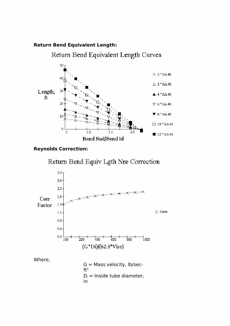
8/16/2019 17730094 Fired Heaters
http://slidepdf.com/reader/full/17730094-fired-heaters 108/141
Return Ben( E u) a/ent Length
Re.no/(* Correct)on
Chere%1 5ass velocity% lbJsec"ftD i Inside tube diameter%in
8/16/2019 17730094 Fired Heaters
http://slidepdf.com/reader/full/17730094-fired-heaters 109/141
isc iscosity% cp
$ow that we have all the details described% we can calculate thepressure drop for some typical heater coils.
'a* S)(e Pre**ure Dro1 Acro** Tu+e*
The gas side pressure drop may be calculated by any number ofmethods available today% but the following procedures should give
sufficient results for heater design.
Bare Tu+e Pre**ure Lo**For bare tubes we can use the method presented byCinpress6Hydrocarbon Processing% >,G7%
∆ 1 7 P 9! 8 N r
Chere% ∆p Pressure drop% inH )Pv elocity head of gas%inH )$ r $umber of tube rows
/nd the velocity head can be described as%P 7 % !$ 8 2' n 9# 3 ! 9 ρ g
Chere%1 n 5ass velocity of gas% lbJhr"
ftρ g Density of gas% lbJft G
The 5ass velocity is described as%' n 7 6 g 9 A n
Chere%C g 5as gas flow%lbJhr/ n $et free area% ft
/nd%
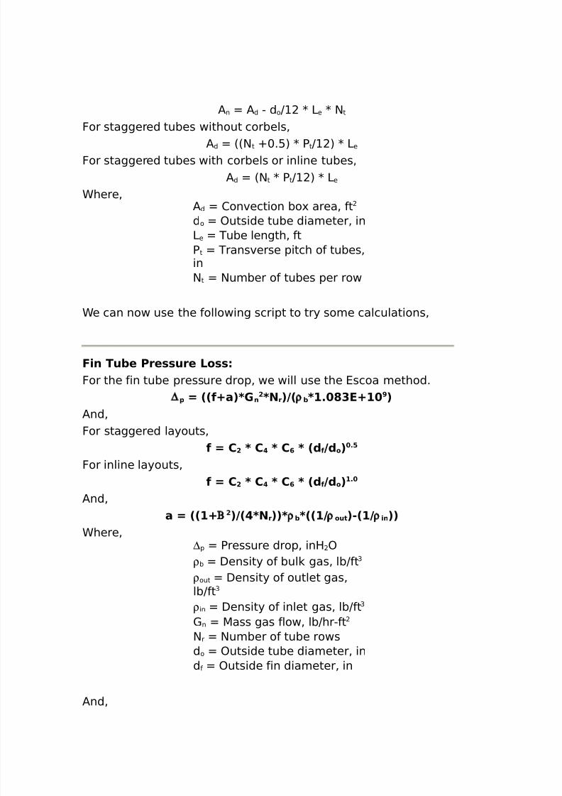
8/16/2019 17730094 Fired Heaters
http://slidepdf.com/reader/full/17730094-fired-heaters 110/141
/ n / d " d oJ K 3 e K $ t
For staggered tubes without corbels%/ d 66$ t O+.:7 K P tJ 7 K 3e
For staggered tubes with corbels or inline tubes%/ d 6$ t K PtJ 7 K 3e
Chere%/ d 2onvection bo' area% ftd o )utside tube diameter% in3e Tube length% ftP t Transverse pitch of tubes%in
$ t $umber of tubes per row
Ce can now use the following script to try some calculations%
F)n Tu+e Pre**ure Lo**For the fin tube pressure drop% we will use the 4scoa method.
∆ 1 7 22f:a38' n! 8N r392ρ +8#% ?$E:# >3
/nd%For staggered layouts%
f 7 C ! 8 C 8 C @ 8 2( f 9( o 3 %=
For inline layouts%f 7 C ! 8 C 8 C @ 8 2( f 9( o 3#%
/nd%a 7 22#: ! 392 8N r338ρ +822#9ρ out 3"2#9ρ )n 33
Chere%∆p Pressure drop% inH )ρ b Density of bul gas% lbJft G
ρ out Density of outlet gas%lbJft G
ρ in Density of inlet gas% lbJft G
1 n 5ass gas flow% lbJhr"ft$ r $umber of tube rowsd o )utside tube diameter% ind f )utside fin diameter% in
/nd%
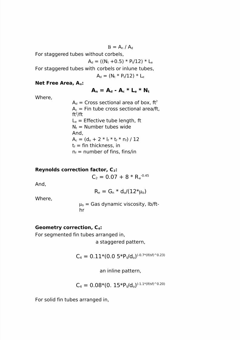
8/16/2019 17730094 Fired Heaters
http://slidepdf.com/reader/full/17730094-fired-heaters 111/141
Β / n J / d
For staggered tubes without corbels%/ d 66$ t O+.:7 K P tJ 7 K 3e
For staggered tubes with corbels or inlune tubes%/ d 6$ t K PtJ 7 K 3e
Net Free Area4 A n
An 7 A ( " A c 8 L e 8 N t
Chere%/ d 2ross sectional area of bo'% ft/ c Fin tube cross sectional areaJft%ft Jft3e 4ffective tube length% ft$ t $umber tubes wide/nd%/ c 6d o O K l f K t f K n f 7 J t f fin thic ness% inn f number of fins% finsJin
Re.no/(* correct)on factor4 C !
2 +.+< O * K R e"+.@:
/nd%Re 1 n K d oJ6 Kµb7
Chere%µb 1as dynamic viscosity% lbJft"hr
'eometr. correct)on4 CFor segmented fin tubes arranged in%
a staggered pattern%
2 @ +. K6+.+ :KP tJd o76"+.<K6lfJsf7Q+. G7
an inline pattern%
2 @ +.+*K6+. :KP tJd o76" . K6lfJsf7Q+. +7
For solid fin tubes arranged in%
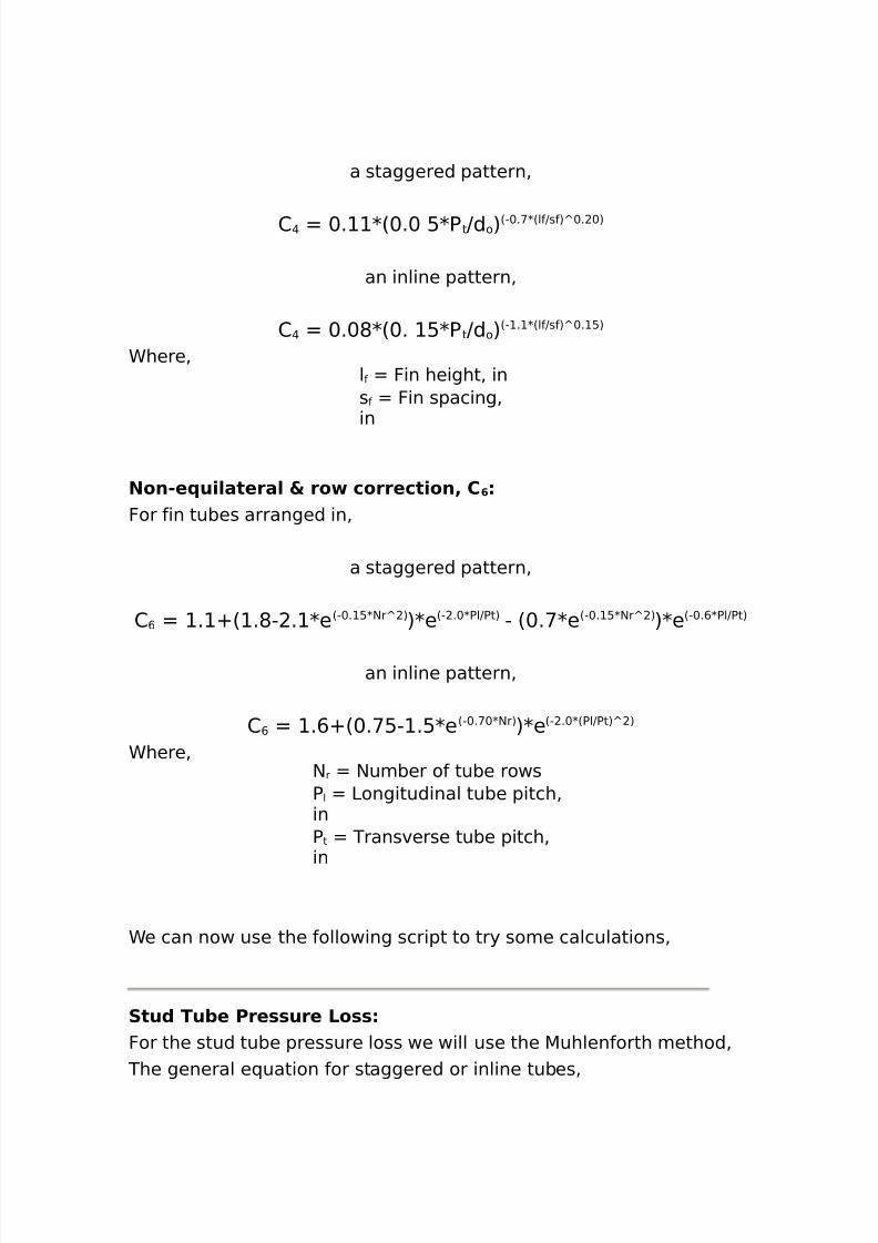
8/16/2019 17730094 Fired Heaters
http://slidepdf.com/reader/full/17730094-fired-heaters 112/141
a staggered pattern%
2 @ +. K6+.+ :KP tJd o76"+.<K6lfJsf7Q+. +7
an inline pattern%
2 @ +.+*K6+. :KP tJd o76" . K6lfJsf7Q+. :7
Chere%lf Fin height% ins f Fin spacing%in
Non"e u)/atera/ 5 ro correct)on4 C @
For fin tubes arranged in%
a staggered pattern%
2 , . O6 .*" . Ke 6"+. :K$rQ 7 7Ke6" .+KPlJPt7 " 6+.<Ke 6"+. :K$rQ 7 7Ke6"+.,KPlJPt7
an inline pattern%
2 , .,O6+.<:" .:Ke 6"+.<+K$r7 7Ke6" .+K6PlJPt7Q 7
Chere%$ r $umber of tube rowsP l 3ongitudinal tube pitch%inP t Transverse tube pitch%in
Ce can now use the following script to try some calculations%
Stu( Tu+e Pre**ure Lo**For the stud tube pressure loss we will use the 5uhlenforth method%
The general e(uation for staggered or inline tubes%
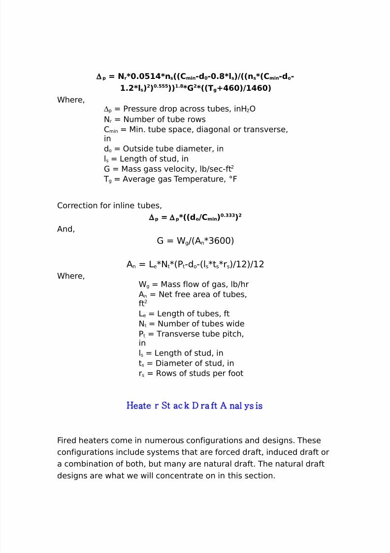
8/16/2019 17730094 Fired Heaters
http://slidepdf.com/reader/full/17730094-fired-heaters 113/141
∆ 1 7 N r8 % =# 8n *22Cm)n "( " %?8/*3922n*82Cm)n "( o "#%!8/ *3! 3 %===33#%?8' ! 822Tg : @ 39# @ 3
Chere%∆p Pressure drop across tubes% inH )$ r $umber of tube rows2 min 5in. tube space% diagonal or transverse%ind o )utside tube diameter% inls 3ength of stud% in1 5ass gass velocity% lbJsec"ft
T g /verage gas Temperature% ;F
2orrection for inline tubes%∆ 1 7 ∆ 1 822( o 9Cm)n 3 %$$$ 3!
/nd%1 C gJ6/ nKG,++7
/ n 3 e K$ tK6Pt"d o"6lsKtsKrs7J 7JChere%
C g 5ass flow of gas% lbJhr/ n $et free area of tubes%ft3e 3ength of tubes% ft$ t $umber of tubes wideP t Transverse tube pitch%inls 3ength of stud% int s Diameter of stud% inr s Rows of studs per foot
Heate r St ac ' * ra ft % nal ys is
Fired heaters come in numerous configurations and designs. Theseconfigurations include systems that are forced draft% induced draft ora combination of both% but many are natural draft. The natural draftdesigns are what we will concentrate on in this section.
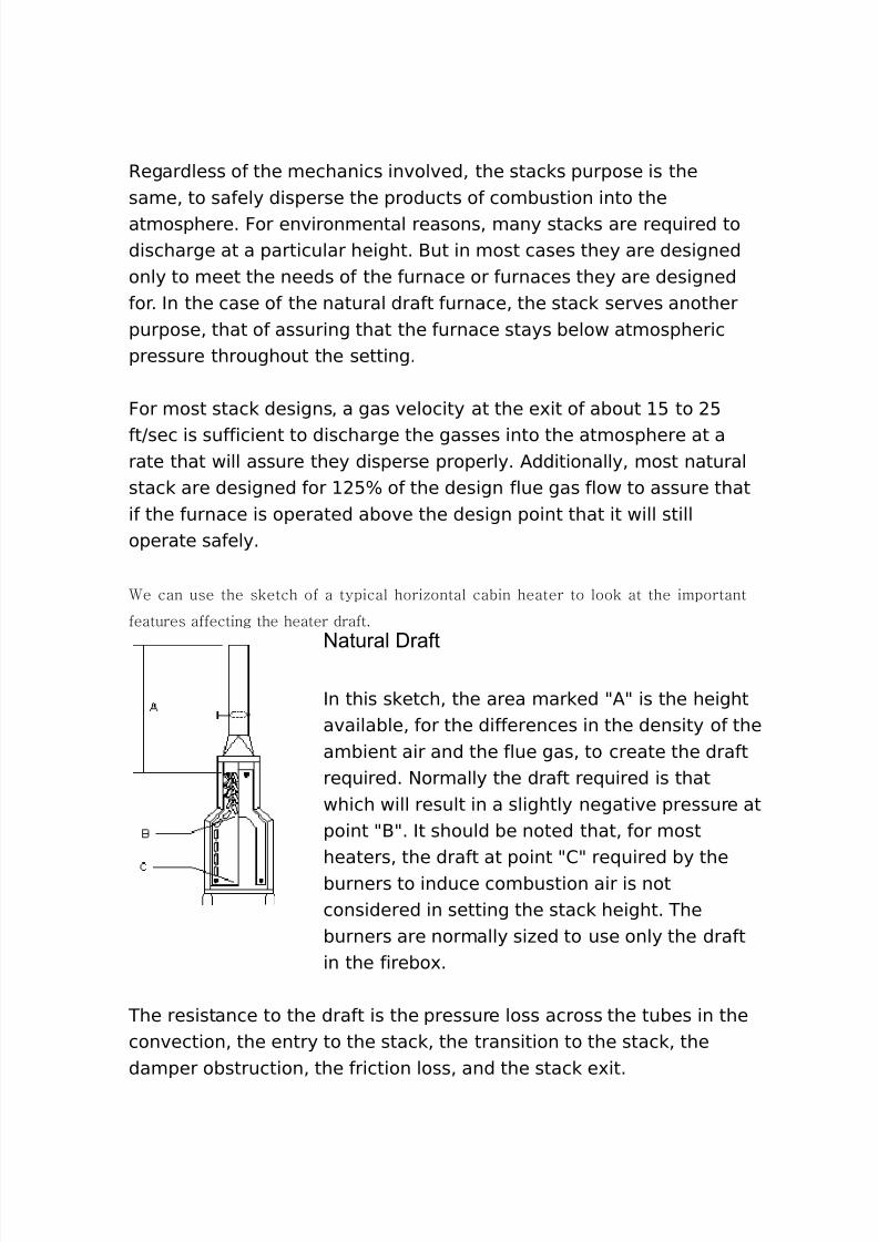
8/16/2019 17730094 Fired Heaters
http://slidepdf.com/reader/full/17730094-fired-heaters 114/141
Regardless of the mechanics involved% the stac s purpose is thesame% to safely disperse the products of combustion into theatmosphere. For environmental reasons% many stac s are re(uired todischarge at a particular height. -ut in most cases they are designedonly to meet the needs of the furnace or furnaces they are designedfor. In the case of the natural draft furnace% the stac serves anotherpurpose% that of assuring that the furnace stays below atmosphericpressure throughout the setting.
For most stac designs% a gas velocity at the e'it of about : to :
ftJsec is sufficient to discharge the gasses into the atmosphere at arate that will assure they disperse properly. /dditionally% most naturalstac are designed for :B of the design flue gas flow to assure thatif the furnace is operated above the design point that it will stilloperate safely.
e can use the s'etch of a typical hori+ontal cabin heater to loo' at the important
features affecting the heater draft.
/atural Draft
In this s etch% the area mar ed 9/9 is the heightavailable% for the differences in the density of theambient air and the flue gas% to create the draftre(uired. $ormally the draft re(uired is thatwhich will result in a slightly negative pressure atpoint 9-9. It should be noted that% for mostheaters% the draft at point 929 re(uired by theburners to induce combustion air is notconsidered in setting the stac height. Theburners are normally si#ed to use only the draftin the firebo'.
The resistance to the draft is the pressure loss across the tubes in theconvection% the entry to the stac % the transition to the stac % thedamper obstruction% the friction loss% and the stac e'it.
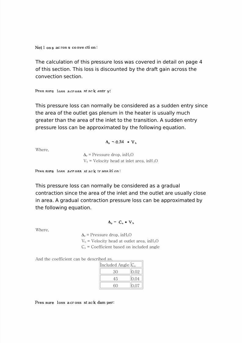
8/16/2019 17730094 Fired Heaters
http://slidepdf.com/reader/full/17730094-fired-heaters 115/141
!et l os s ac ros s co n$e cti on:
The calculation of this pressure loss was covered in detail on page @of this section. This loss is discounted by the draft gain across theconvection section.
,res sure loss a cr oss st ac ' entr y:
This pressure loss can normally be considered as a sudden entry sincethe area of the outlet gas plenum in the heater is usually much
greater than the area of the inlet to the transition. / sudden entrypressure loss can be appro'imated by the following e(uation.
∆ p - ./0 1 2 h
here(∆p - ,ressure drop( inH 34
2 h - 2elocity head at inlet area( inH 34
,res sure loss a cr oss st ac ' tr ans iti on:
This pressure loss can normally be considered as a gradualcontraction since the area of the inlet and the outlet are usually closein area. / gradual contraction pressure loss can be appro'imated bythe following e(uation.
∆ p - C a 1 2 h
here(∆p - ,ressure drop( inH 34
2 h - 2elocity head at outlet area( inH 34C a - Coefficient based on included angle
%nd the coefficient can be described as(5ncluded %ngle C a
/ . 3
06 . 0
" . 7
,res sure loss a cross st ac' dam per:
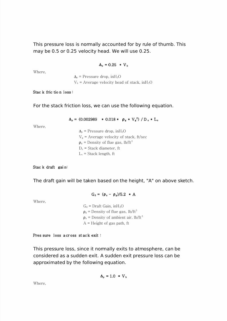
8/16/2019 17730094 Fired Heaters
http://slidepdf.com/reader/full/17730094-fired-heaters 116/141
This pressure loss is normally accounted for by rule of thumb. Thismay be +.: or +. : velocity head. Ce will use +. :.
∆ p - .36 1 2 h
here(∆p - ,ressure drop( inH 342 h - %$erage $elocity head of stac'( inH 34
Stac ' fric tio n loss :
For the stac friction loss% we can use the following e(uation.
∆ p - 8 . 39 9 1 . ; 1 ρ g 1 2 g3 < = * s 1 > s
here(∆p - ,ressure drop( inH 34
2 g - %$erage $elocity of stac'( ft=secρ g - *ensity of flue gas( lb=ft /
* s - Stac' diameter( ft> s - Stac' length( ft
Stac ' draft gai n:
The draft gain will be ta en based on the height% 9/9 on above s etch.
? d - 8 ρ a @ ρ g <=6.3 1 %
here(? d - *raft ?ain( inH 34ρ g - *ensity of flue gas( lb=ft /
ρ a - *ensity of ambient air( lb=ft /
% - Height of gas path( ft
,res sure loss a cr oss st ac ' exit :
This pressure loss% since it normally e'its to atmosphere% can beconsidered as a sudden e'it. / sudden e'it pressure loss can beappro'imated by the following e(uation.
∆ p - ;. 1 2 h
here(
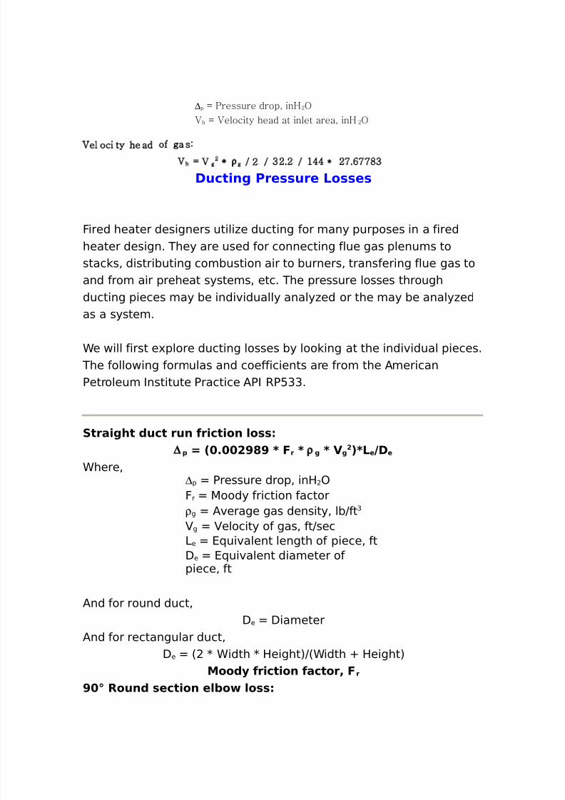
8/16/2019 17730094 Fired Heaters
http://slidepdf.com/reader/full/17730094-fired-heaters 117/141
∆p - ,ressure drop( inH 34
2 h - 2elocity head at inlet area( inH 34
2el oci ty head of ga s:
2 h - 2 g3 1 ρ g = 3 = /3.3 = ;00 1 37."77 /
Duct)ng Pre**ure Lo**e*
Fired heater designers utili#e ducting for many purposes in a firedheater design. They are used for connecting flue gas plenums tostac s% distributing combustion air to burners% transfering flue gas to
and from air preheat systems% etc. The pressure losses throughducting pieces may be individually analy#ed or the may be analy#edas a system.
Ce will first e'plore ducting losses by loo ing at the individual pieces. The following formulas and coefficients are from the /mericanPetroleum Institute Practice /PI RP:GG.
Stra)ght (uct run fr)ct)on /o**∆ 1 7 2 % !>?> 8 F r 8 ρ g 8 V g
! 38Le 9De
Chere%∆p Pressure drop% inH )Fr 5oody friction factorρ g /verage gas density% lbJft G
g elocity of gas% ftJsec3e 4(uivalent length of piece% ft
De 4(uivalent diameter ofpiece% ft
/nd for round duct%De Diameter
/nd for rectangular duct%De 6 K Cidth K Height7J6Cidth O Height7
Moo(. fr)ct)on factor4 F r
> Roun( *ect)on e/+o /o**
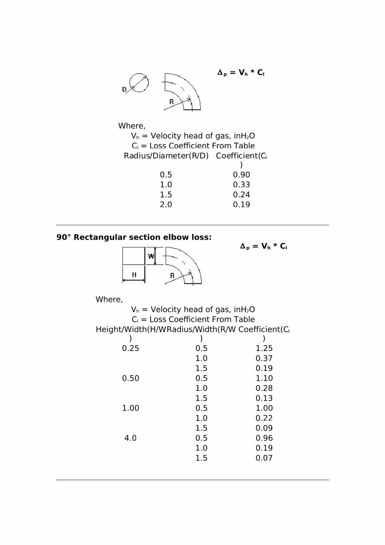
8/16/2019 17730094 Fired Heaters
http://slidepdf.com/reader/full/17730094-fired-heaters 118/141
∆ 1 7 V h 8 C /
Chere%h elocity head of gas% inH )
2 l 3oss 2oefficient From TableRadiusJDiameter6RJD7 2oefficient62 l
7+.: +.>+
.+ +.GG
.: +. @
.+ +. >
> Rectangu/ar *ect)on e/+o /o**∆ 1 7 V h 8 C /
Chere%h elocity head of gas% inH )
2 l 3oss 2oefficient From TableHeightJCidth6HJC
7RadiusJCidth6RJC
72oefficient62 l
7+. : +.: . :
.+ +.G<
.: +. >
+.:+ +.: . +.+ +. *.: +. G
.++ +.: .++.+ +..: +.+>
@.+ +.: +.>,.+ +. >.: +.+<
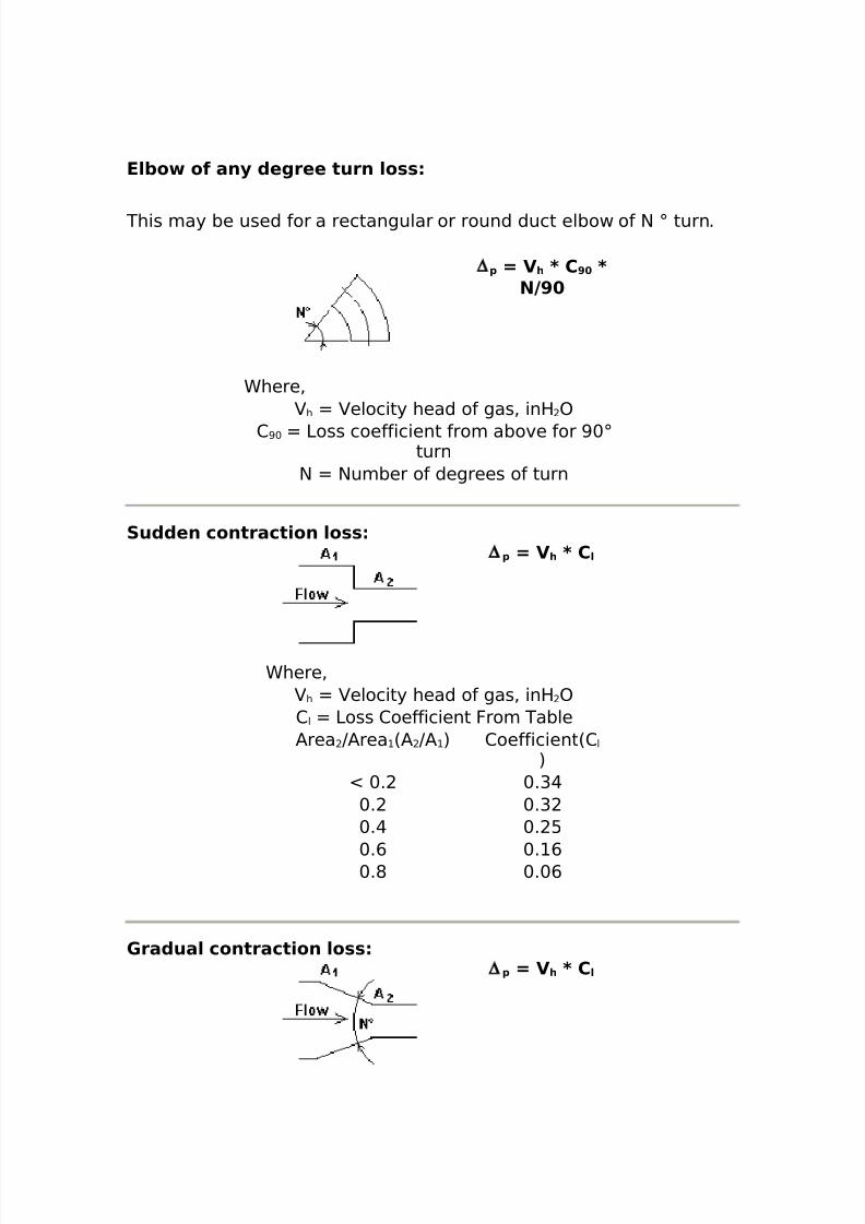
8/16/2019 17730094 Fired Heaters
http://slidepdf.com/reader/full/17730094-fired-heaters 119/141
E/+o of an. (egree turn /o**
This may be used for a rectangular or round duct elbow of $ ; turn.
∆ 1 7 V h 8 C > 8N9>
Chere%h elocity head of gas% inH )
2 >+ 3oss coefficient from above for >+;turn
$ $umber of degrees of turn
Su((en contract)on /o**∆ 1 7 V h 8 C /
Chere%h elocity head of gas% inH )
2 l 3oss 2oefficient From Table/rea J/rea 6/ J/ 7 2oefficient62 l
7N +. +.G@
+. +.G+.@ +. :
+., +. ,+.* +.+,
'ra(ua/ contract)on /o**∆ 1 7 V h 8 C /
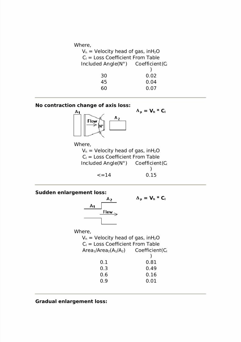
8/16/2019 17730094 Fired Heaters
http://slidepdf.com/reader/full/17730094-fired-heaters 120/141
Chere%h elocity head of gas% inH )
2 l 3oss 2oefficient From TableIncluded /ngle6$;7 2oefficient62 l
7G+ +.+@: +.+@,+ +.+<
No contract)on change of a0)* /o**∆ 1 7 V h 8 C /
Chere%h elocity head of gas% inH )
2 l 3oss 2oefficient From TableIncluded /ngle6$;7 2oefficient62 l
7N @ +. :
Su((en en/argement /o**∆ 1 7 V h 8 C /
Chere%
h elocity head of gas% inH )2 l 3oss 2oefficient From Table/rea J/rea 6/ J/ 7 2oefficient62 l
7+. +.*+.G +.@>+., +. ,+.> +.+
'ra(ua/ en/argement /o**
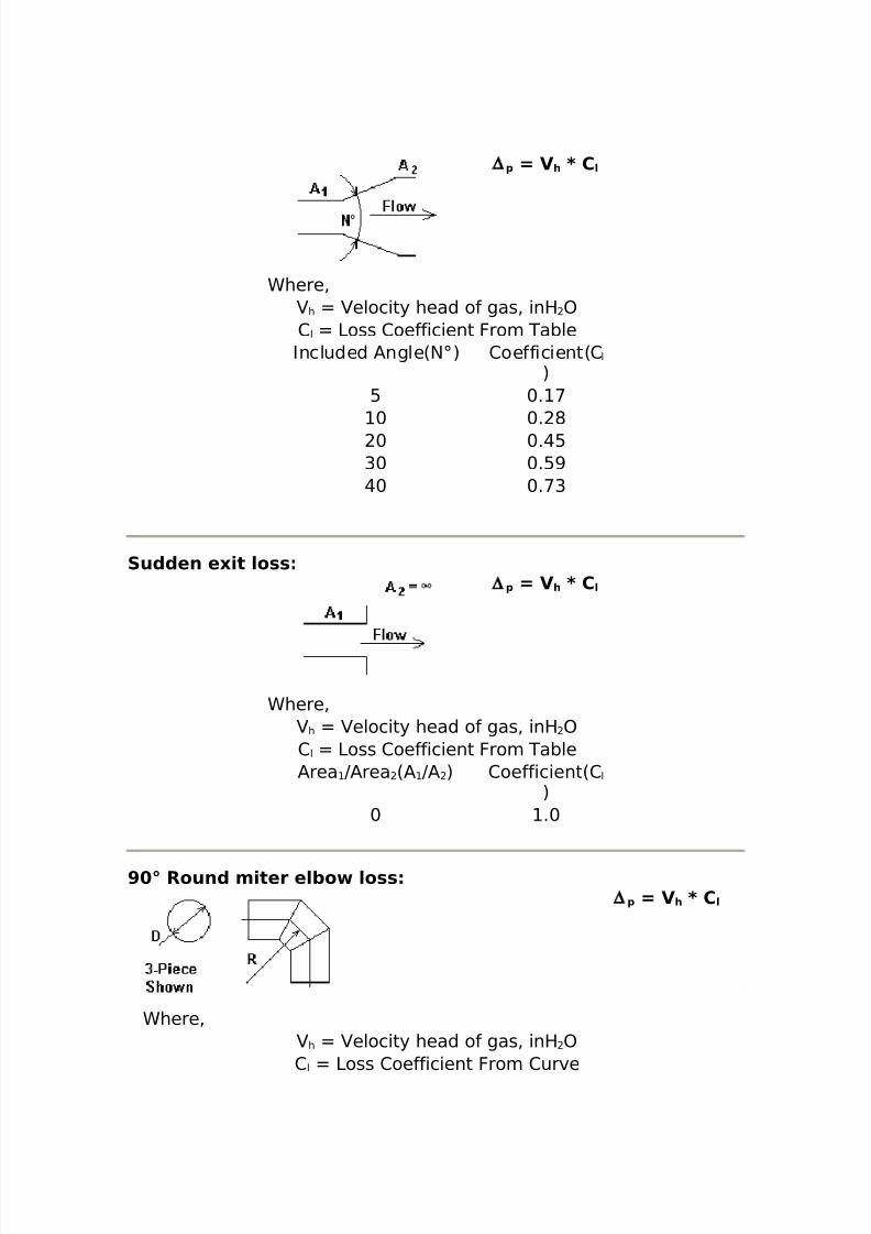
8/16/2019 17730094 Fired Heaters
http://slidepdf.com/reader/full/17730094-fired-heaters 121/141
∆ 1 7 V h 8 C /
Chere%h elocity head of gas% inH )
2 l 3oss 2oefficient From TableIncluded /ngle6$;7 2oefficient62 l
7: +. <+ +. *+ +.@:
G+ +.:>@+ +.<G
Su((en e0)t /o**∆ 1 7 V h 8 C /
Chere%h elocity head of gas% inH )
2 l 3oss 2oefficient From Table/rea J/rea 6/ J/ 7 2oefficient62 l
7+ .+
> Roun( m)ter e/+o /o**∆ 1 7 V h 8 C /
Chere%h elocity head of gas% inH )
2 l 3oss 2oefficient From 2urve
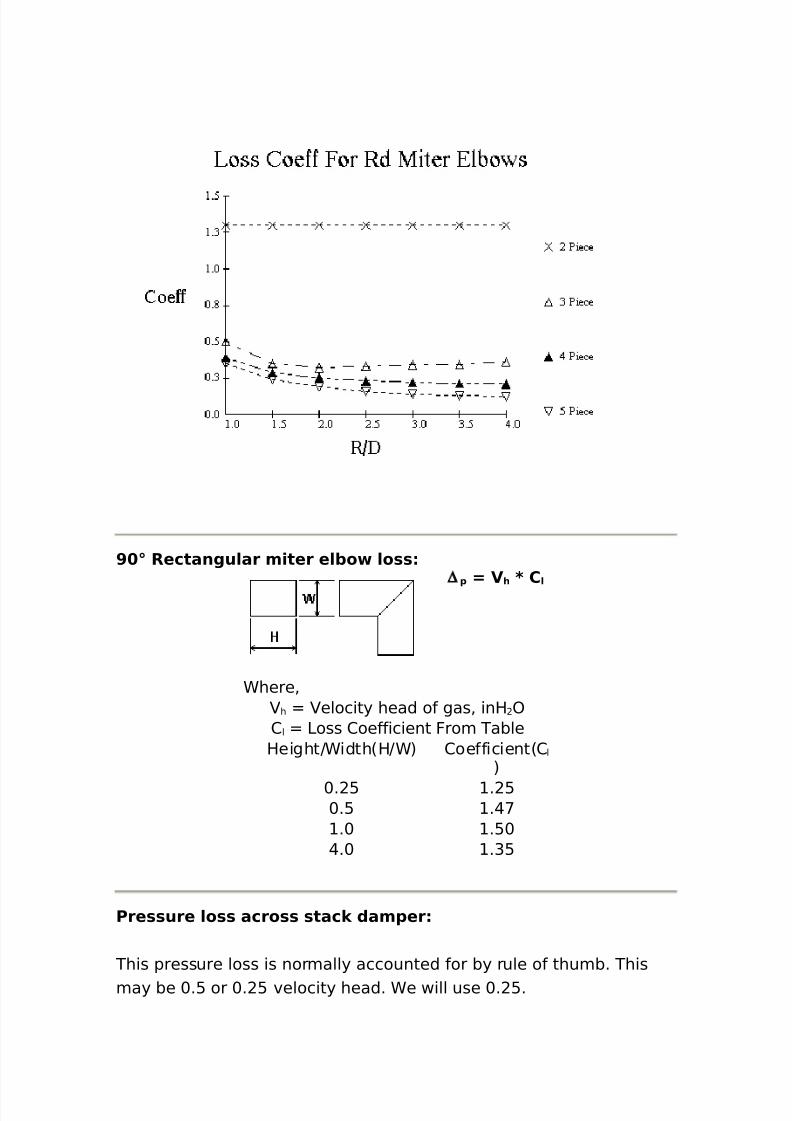
8/16/2019 17730094 Fired Heaters
http://slidepdf.com/reader/full/17730094-fired-heaters 122/141
> Rectangu/ar m)ter e/+o /o**∆ 1 7 V h 8 C /
Chere%h elocity head of gas% inH )
2 l 3oss 2oefficient From TableHeightJCidth6HJC7 2oefficient62 l
7
+. : . :+.: .@<
.+ .:+@.+ .G:
Pre**ure /o** acro** *tac, (am1er
This pressure loss is normally accounted for by rule of thumb. Thismay be +.: or +. : velocity head. Ce will use +. :.
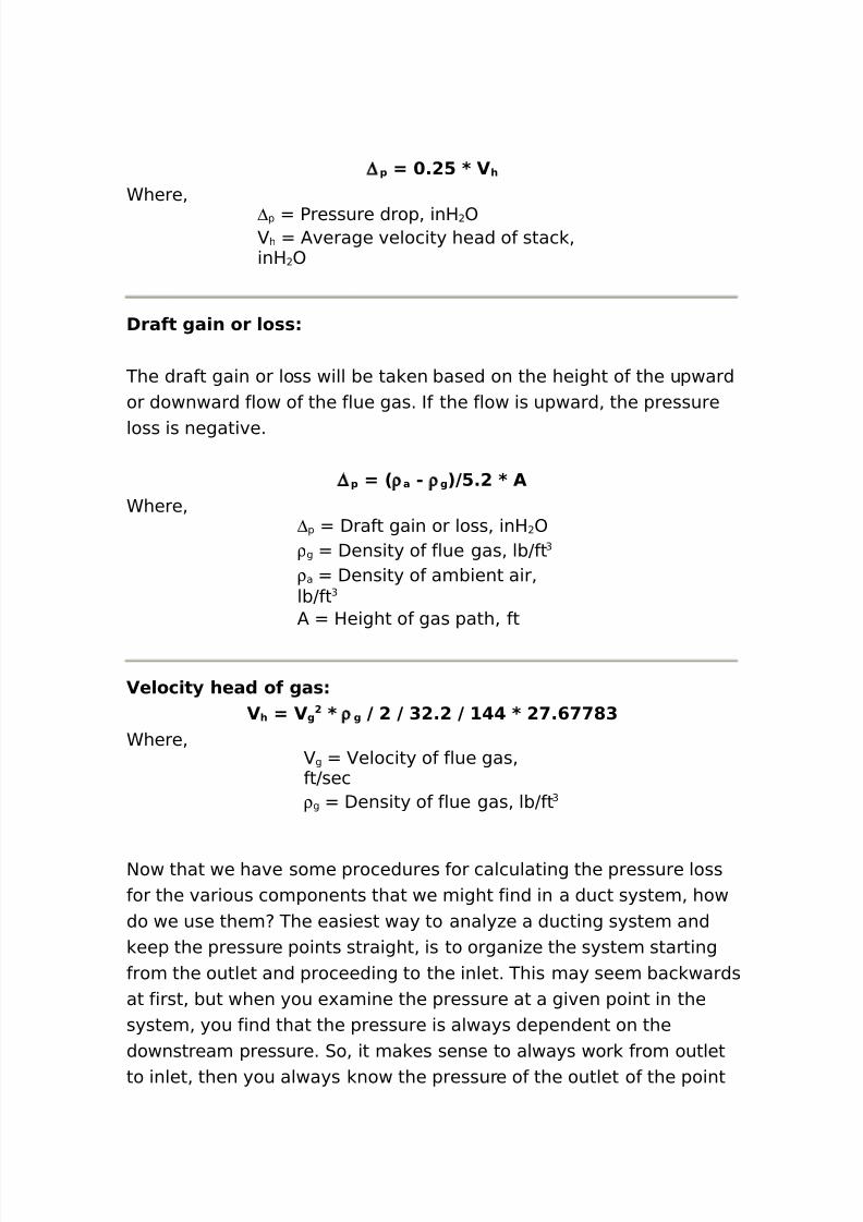
8/16/2019 17730094 Fired Heaters
http://slidepdf.com/reader/full/17730094-fired-heaters 123/141
∆ 1 7 %!= 8 V h
Chere%∆p Pressure drop% inH )
h /verage velocity head of stac %inH )
Draft ga)n or /o**
The draft gain or loss will be ta en based on the height of the upwardor downward flow of the flue gas. If the flow is upward% the pressure
loss is negative.
∆ 1 7 2 ρ a " ρ g 39=%! 8 AChere%
∆p Draft gain or loss% inH )ρ g Density of flue gas% lbJft G
ρ a Density of ambient air%lbJft G
/ Height of gas path% ft
Ve/oc)t. hea( of ga*Vh 7 V g
! 8 ρ g 9 ! 9 $!%! 9 # 8 ! %@ ?$Chere%
g elocity of flue gas%ftJsecρ g Density of flue gas% lbJft G
$ow that we have some procedures for calculating the pressure lossfor the various components that we might find in a duct system% howdo we use them The easiest way to analy#e a ducting system and
eep the pressure points straight% is to organi#e the system startingfrom the outlet and proceeding to the inlet. This may seem bac wardsat first% but when you e'amine the pressure at a given point in thesystem% you find that the pressure is always dependent on thedownstream pressure. 0o% it ma es sense to always wor from outletto inlet% then you always now the pressure of the outlet of the point
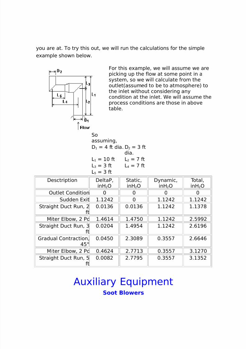
8/16/2019 17730094 Fired Heaters
http://slidepdf.com/reader/full/17730094-fired-heaters 124/141
you are at. To try this out% we will run the calculations for the simplee'ample shown below.
For this e'ample% we will assume we arepic ing up the flow at some point in asystem% so we will calculate from theoutlet6assumed to be to atmosphere7 tothe inlet without considering anycondition at the inlet. Ce will assume theprocess conditions are those in abovetable.
0oassuming%D @ ft dia. D G ft
dia.3 + ft 3 < ft3G G ft 3 @ < ft3 : G ft
Desctription DeltaP%inH )
0tatic%inH )
Dynamic%inH )
Total%inH )
)utlet 2ondition + + + +0udden 4'it . @ + . @ . @
0traight Duct Run% ft
+.+ G, +.+ G, . @ . G<*
5iter 4lbow% Pc .@, @ .@<:+ . @ .:>>0traight Duct Run% G
ft+.+ +@ .@>:@ . @ ., >,
1radual 2ontraction%
@:;
+.+@:+ .G+*> +.G::< .,,@,
5iter 4lbow% Pc +.@, @ .<< G +.G::< G. <+0traight Duct Run% :
ft+.++* .<<>: +.G::< G. G:
/u'iliary 4(uipmentSoot B/o er*
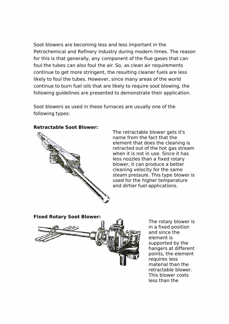
8/16/2019 17730094 Fired Heaters
http://slidepdf.com/reader/full/17730094-fired-heaters 125/141
0oot blowers are becoming less and less important in thePetrochemical and Refinery industry during modern times. The reasonfor this is that generally% any component of the flue gases that canfoul the tubes can also foul the air. 0o% as clean air re(uirementscontinue to get more stringent% the resulting cleaner fuels are lessli ely to foul the tubes. However% since many areas of the worldcontinue to burn fuel oils that are li ely to re(uire soot blowing% thefollowing guidelines are presented to demonstrate their application.
0oot blowers as used in these furnaces are usually one of the
following typesL
Retracta+/e Soot B/o er The retractable blower gets itAsname from the fact that theelement that does the cleaning isretracted out of the hot gas streamwhen it is not in use. 0ince it hasless no##les than a fi'ed rotaryblower% it can produce a better
cleaning velocity for the samesteam pressure. This type blower isused for the higher temperatureand dirtier fuel applications.
F)0e( Rotar. Soot B/o er The rotary blower is
in a fi'ed positionand since theelement issupported by thehangers at differentpoints% the elementre(uires lessmaterial than theretractable blower.
This blower costsless than the
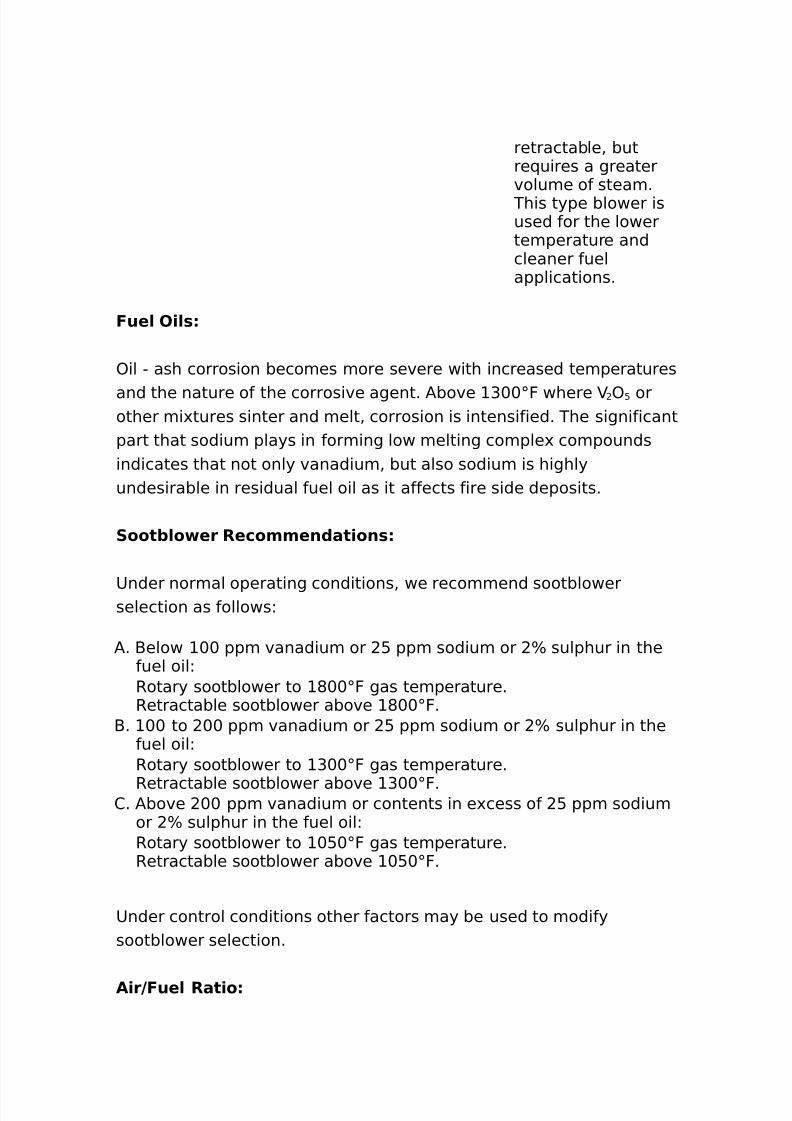
8/16/2019 17730094 Fired Heaters
http://slidepdf.com/reader/full/17730094-fired-heaters 126/141
retractable% butre(uires a greatervolume of steam.
This type blower isused for the lowertemperature andcleaner fuelapplications.
Fue/ O)/*
)il " ash corrosion becomes more severe with increased temperatures
and the nature of the corrosive agent. /bove G++;F where ) : orother mi'tures sinter and melt% corrosion is intensified. The significantpart that sodium plays in forming low melting comple' compoundsindicates that not only vanadium% but also sodium is highlyundesirable in residual fuel oil as it affects fire side deposits.
Soot+/o er Recommen(at)on*
8nder normal operating conditions% we recommend sootblowerselection as followsL
/. -elow ++ ppm vanadium or : ppm sodium or B sulphur in thefuel oilLRotary sootblower to *++;F gas temperature.Retractable sootblower above *++;F.
-. ++ to ++ ppm vanadium or : ppm sodium or B sulphur in thefuel oilLRotary sootblower to G++;F gas temperature.
Retractable sootblower above G++;F.2. /bove ++ ppm vanadium or contents in e'cess of : ppm sodium
or B sulphur in the fuel oilLRotary sootblower to +:+;F gas temperature.Retractable sootblower above +:+;F.
8nder control conditions other factors may be used to modifysootblower selection.
A)r9Fue/ Rat)o
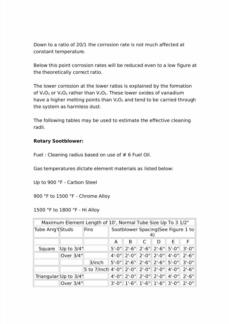
8/16/2019 17730094 Fired Heaters
http://slidepdf.com/reader/full/17730094-fired-heaters 127/141
Down to a ratio of +J the corrosion rate is not much affected atconstant temperature.
-elow this point corrosion rates will be reduced even to a low figure atthe theoretically correct ratio.
The lower corrosion at the lower ratios is e'plained by the formationof ) G or ) @ rather than ) : . These lower o'ides of vanadiumhave a higher melting points than ) : and tend to be carried throughthe system as harmless dust.
The following tables may be used to estimate the effective cleaningradii.
Rotar. Soot+/o er
Fuel L 2leaning radius based on use of M , Fuel )il.
1as temperatures dictate element materials as listed belowL
8p to >++ ;F " 2arbon 0teel
>++ ;F to :++ ;F " 2hrome /lloy
:++ ;F to *++ ;F " Hi /lloy
5a'imum 4lement 3ength of +A% $ormal Tube 0i#e 8p To G J 9 Tube /rrgAt 0tuds Fins 0ootblower 0pacing60ee Figure to
@7/ - 2 D 4 F
0(uare 8p to GJ@9 :A"+9 A",9 A",9 A",9 :A"+9 GA"+9)ver GJ@9 @A"+9 A"+9 A"+9 A"+9 @A"+9 A",9
GJinch :A"+9 A",9 A",9 A",9 :A"+9 GA"+9: to <Jinch @A"+9 A"+9 A"+9 A"+9 @A"+9 A",9
Triangular 8p to GJ@9 @A"+9 A"+9 A"+9 A"+9 @A"+9 A",9
)ver GJ@9 GA"+9 A",9 A",9 A",9 GA"+9 A"+9
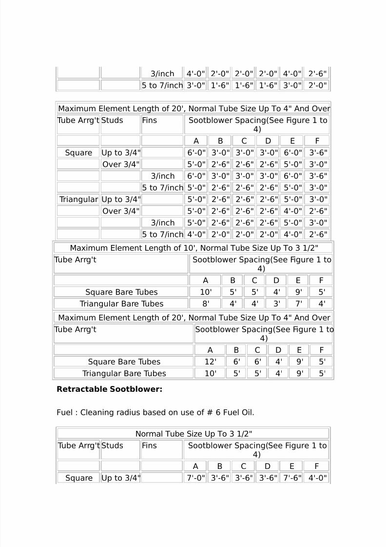
8/16/2019 17730094 Fired Heaters
http://slidepdf.com/reader/full/17730094-fired-heaters 128/141
GJinch @A"+9 A"+9 A"+9 A"+9 @A"+9 A",9: to <Jinch GA"+9 A",9 A",9 A",9 GA"+9 A"+9
5a'imum 4lement 3ength of +A% $ormal Tube 0i#e 8p To @9 /nd )ver Tube /rrgAt 0tuds Fins 0ootblower 0pacing60ee Figure to
@7/ - 2 D 4 F
0(uare 8p to GJ@9 ,A"+9 GA"+9 GA"+9 GA"+9 ,A"+9 GA",9)ver GJ@9 :A"+9 A",9 A",9 A",9 :A"+9 GA"+9
GJinch ,A"+9 GA"+9 GA"+9 GA"+9 ,A"+9 GA",9
: to <Jinch :A"+9 A",9 A",9 A",9 :A"+9 GA"+9 Triangular 8p to GJ@9 :A"+9 A",9 A",9 A",9 :A"+9 GA"+9)ver GJ@9 :A"+9 A",9 A",9 A",9 @A"+9 A",9
GJinch :A"+9 A",9 A",9 A",9 :A"+9 GA"+9: to <Jinch @A"+9 A"+9 A"+9 A"+9 @A"+9 A",9
5a'imum 4lement 3ength of +A% $ormal Tube 0i#e 8p To G J 9 Tube /rrgAt 0ootblower 0pacing60ee Figure to
@7/ - 2 D 4 F
0(uare -are Tubes +A :A :A @A >A :A Triangular -are Tubes *A @A @A GA <A @A
5a'imum 4lement 3ength of +A% $ormal Tube 0i#e 8p To @9 /nd )ver Tube /rrgAt 0ootblower 0pacing60ee Figure to
@7/ - 2 D 4 F
0(uare -are Tubes A ,A ,A @A >A :A Triangular -are Tubes +A :A :A @A >A :A
Retracta+/e Soot+/o er
Fuel L 2leaning radius based on use of M , Fuel )il.
$ormal Tube 0i#e 8p To G J 9 Tube /rrgAt 0tuds Fins 0ootblower 0pacing60ee Figure to
@7/ - 2 D 4 F
0(uare 8p to GJ@9 <A"+9 GA",9 GA",9 GA",9 <A",9 @A"+9
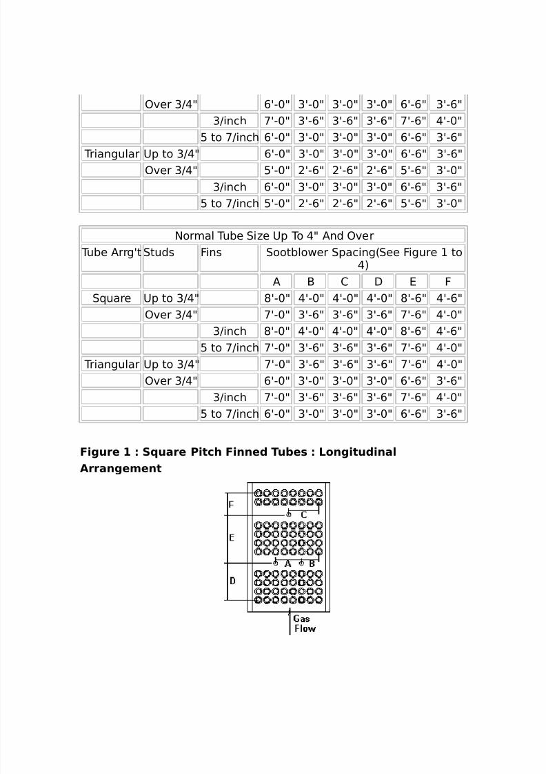
8/16/2019 17730094 Fired Heaters
http://slidepdf.com/reader/full/17730094-fired-heaters 129/141
)ver GJ@9 ,A"+9 GA"+9 GA"+9 GA"+9 ,A",9 GA",9GJinch <A"+9 GA",9 GA",9 GA",9 <A",9 @A"+9
: to <Jinch ,A"+9 GA"+9 GA"+9 GA"+9 ,A",9 GA",9 Triangular 8p to GJ@9 ,A"+9 GA"+9 GA"+9 GA"+9 ,A",9 GA",9
)ver GJ@9 :A"+9 A",9 A",9 A",9 :A",9 GA"+9GJinch ,A"+9 GA"+9 GA"+9 GA"+9 ,A",9 GA",9
: to <Jinch :A"+9 A",9 A",9 A",9 :A",9 GA"+9
$ormal Tube 0i#e 8p To @9 /nd )ver Tube /rrgAt 0tuds Fins 0ootblower 0pacing60ee Figure to
@7/ - 2 D 4 F
0(uare 8p to GJ@9 *A"+9 @A"+9 @A"+9 @A"+9 *A",9 @A",9)ver GJ@9 <A"+9 GA",9 GA",9 GA",9 <A",9 @A"+9
GJinch *A"+9 @A"+9 @A"+9 @A"+9 *A",9 @A",9: to <Jinch <A"+9 GA",9 GA",9 GA",9 <A",9 @A"+9
Triangular 8p to GJ@9 <A"+9 GA",9 GA",9 GA",9 <A",9 @A"+9)ver GJ@9 ,A"+9 GA"+9 GA"+9 GA"+9 ,A",9 GA",9
GJinch <A"+9 GA",9 GA",9 GA",9 <A",9 @A"+9: to <Jinch ,A"+9 GA"+9 GA"+9 GA"+9 ,A",9 GA",9
F)gure # S uare P)tch F)nne( Tu+e* Long)tu()na/Arrangement
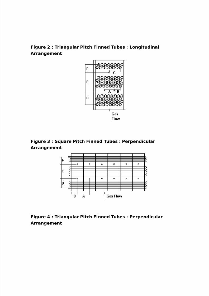
8/16/2019 17730094 Fired Heaters
http://slidepdf.com/reader/full/17730094-fired-heaters 130/141
F)gure ! Tr)angu/ar P)tch F)nne( Tu+e* Long)tu()na/Arrangement
F)gure $ S uare P)tch F)nne( Tu+e* Per1en()cu/arArrangement
F)gure Tr)angu/ar P)tch F)nne( Tu+e* Per1en()cu/arArrangement

8/16/2019 17730094 Fired Heaters
http://slidepdf.com/reader/full/17730094-fired-heaters 131/141
Recommen(e( M)n)mum B/o )ng Pre**ure* Rotar. Soot+/o er
4lement length up to +A ma'imum% tube si#es up to GJ 9 )D
0(uare Pitch :+ psig Triangular Pitch ++ psig
Rotar. Soot+/o er4lement length up to +A up to +A ma'imum% tube si#es @9 )D andover
0(uare Pitch <: psig Triangular Pitch : psig
Retracta+/eSoot+/o er
0(uare Pitch ++psig
TriangularPitch
:+psig
Fan* 5 B/o er*
Fans and blowers% as used in fired heater service%usually fall into one of the following categories.
Forced Draft FansInduced Draft FansPurge Fans
4ach of these purposes are usually served by a
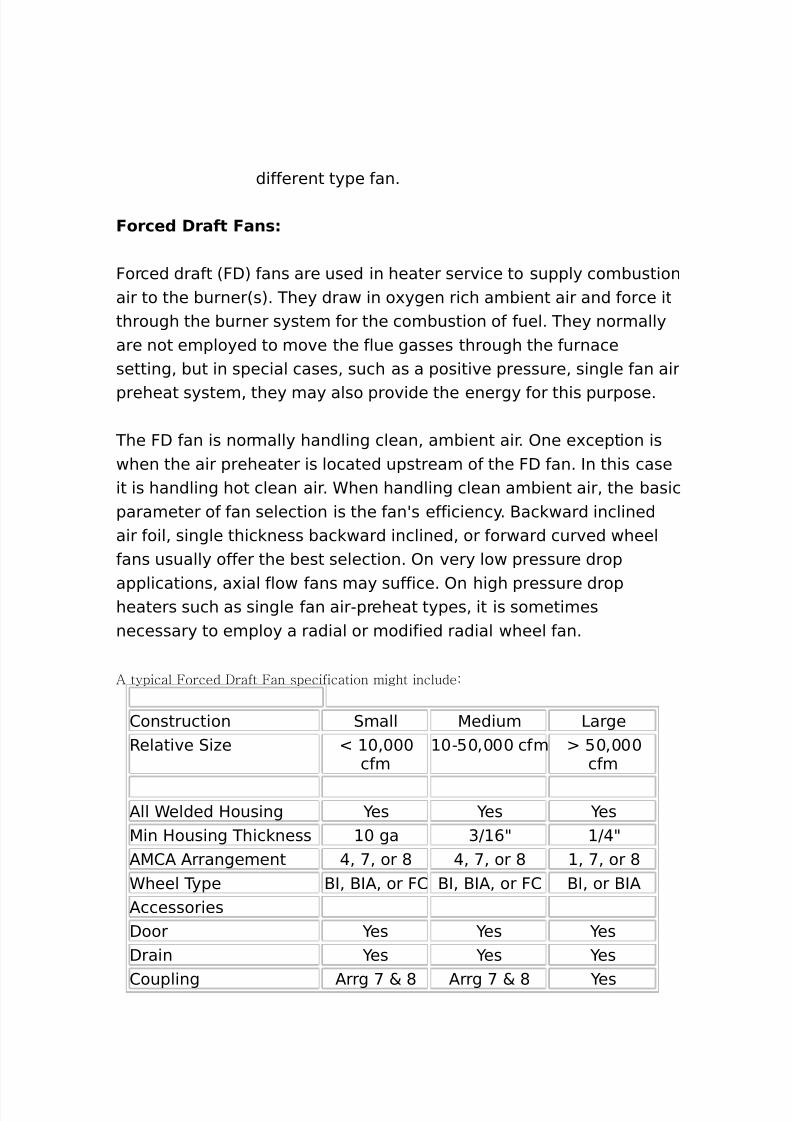
8/16/2019 17730094 Fired Heaters
http://slidepdf.com/reader/full/17730094-fired-heaters 132/141
different type fan.
Force( Draft Fan*
Forced draft 6FD7 fans are used in heater service to supply combustionair to the burner6s7. They draw in o'ygen rich ambient air and force itthrough the burner system for the combustion of fuel. They normallyare not employed to move the flue gasses through the furnacesetting% but in special cases% such as a positive pressure% single fan air
preheat system% they may also provide the energy for this purpose.
The FD fan is normally handling clean% ambient air. )ne e'ception iswhen the air preheater is located upstream of the FD fan. In this caseit is handling hot clean air. Chen handling clean ambient air% the basicparameter of fan selection is the fanAs efficiency. -ac ward inclinedair foil% single thic ness bac ward inclined% or forward curved wheelfans usually offer the best selection. )n very low pressure drop
applications% a'ial flow fans may suffice. )n high pressure dropheaters such as single fan air"preheat types% it is sometimesnecessary to employ a radial or modified radial wheel fan.
% typical Forced *raft Fan specification might include:
2onstruction 0mall 5edium 3argeRelative 0i#e N +%+++
cfm+":+%+++ cfm :+%+++
cfm
/ll Celded Housing es es es5in Housing Thic ness + ga GJ ,9 J@9/52/ /rrangement @% <% or * @% <% or * % <% or *Cheel Type -I% -I/% or F2 -I% -I/% or F2 -I% or -I//ccessoriesDoor es es esDrain es es es
2oupling /rrg < & * /rrg < & * es
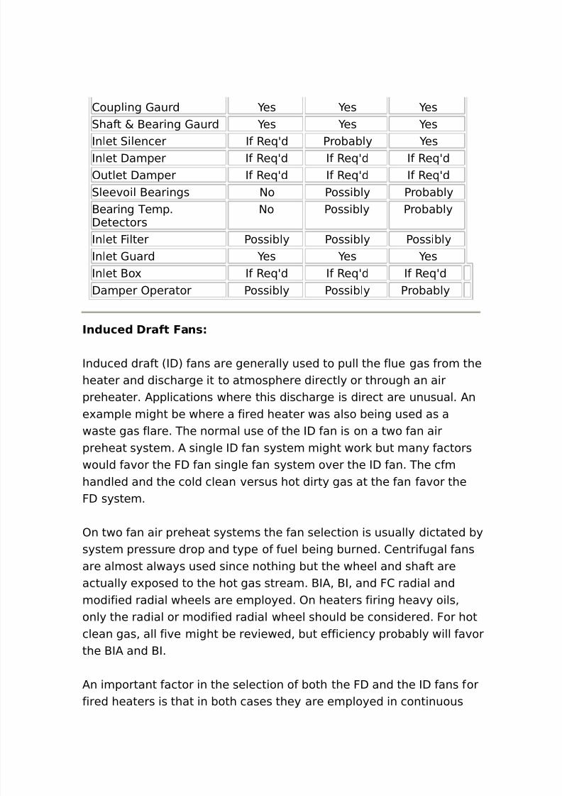
8/16/2019 17730094 Fired Heaters
http://slidepdf.com/reader/full/17730094-fired-heaters 133/141
2oupling 1aurd es es es0haft & -earing 1aurd es es es
Inlet 0ilencer If Re(Ad Probably esInlet Damper If Re(Ad If Re(Ad If Re(Ad)utlet Damper If Re(Ad If Re(Ad If Re(Ad0leevoil -earings $o Possibly Probably-earing Temp.Detectors
$o Possibly Probably
Inlet Filter Possibly Possibly PossiblyInlet 1uard es es es
Inlet -o' If Re(Ad If Re(Ad If Re(AdDamper )perator Possibly Possibly Probably
In(uce( Draft Fan*
Induced draft 6ID7 fans are generally used to pull the flue gas from theheater and discharge it to atmosphere directly or through an airpreheater. /pplications where this discharge is direct are unusual. /n
e'ample might be where a fired heater was also being used as awaste gas flare. The normal use of the ID fan is on a two fan airpreheat system. / single ID fan system might wor but many factorswould favor the FD fan single fan system over the ID fan. The cfmhandled and the cold clean versus hot dirty gas at the fan favor theFD system.
)n two fan air preheat systems the fan selection is usually dictated bysystem pressure drop and type of fuel being burned. 2entrifugal fansare almost always used since nothing but the wheel and shaft areactually e'posed to the hot gas stream. -I/% -I% and F2 radial andmodified radial wheels are employed. )n heaters firing heavy oils%only the radial or modified radial wheel should be considered. For hotclean gas% all five might be reviewed% but efficiency probably will favorthe -I/ and -I.
/n important factor in the selection of both the FD and the ID fans forfired heaters is that in both cases they are employed in continuous
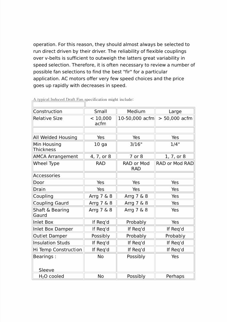
8/16/2019 17730094 Fired Heaters
http://slidepdf.com/reader/full/17730094-fired-heaters 134/141
operation. For this reason% they should almost always be selected torun direct driven by their driver. The reliability of fle'ible couplingsover v"belts is sufficient to outweigh the latters great variability inspeed selection. Therefore% it is often necessary to review a number ofpossible fan selections to find the best 9fir9 for a particularapplication. /2 motors offer very few speed choices and the pricegoes up rapidly with decreases in speed.
% typical 5nduced *raft Fan specification might include:
2onstruction 0mall 5edium 3argeRelative 0i#e N +%+++
acfm+":+%+++ acfm :+%+++ acfm
/ll Celded Housing es es es5in Housing
Thic ness+ ga GJ ,9 J@9
/52/ /rrangement @% <% or * < or * % <% or *Cheel Type R/D R/D or 5od
R/D
R/D or 5od R/D
/ccessoriesDoor es es esDrain es es es2oupling /rrg < & * /rrg < & * es2oupling 1aurd /rrg < & * /rrg < & * es0haft & -earing1aurd
/rrg < & * /rrg < & * es
Inlet -o' If Re(Ad Probably esInlet -o' Damper If Re(Ad If Re(Ad If Re(Ad)utlet Damper Possibly Probably ProbablyInsulation 0tuds If Re(Ad If Re(Ad If Re(AdHi Temp 2onstruction If Re(Ad If Re(Ad If Re(Ad-earings L
0leeve
$o Possibly es
H ) cooled $o Possibly Perhaps
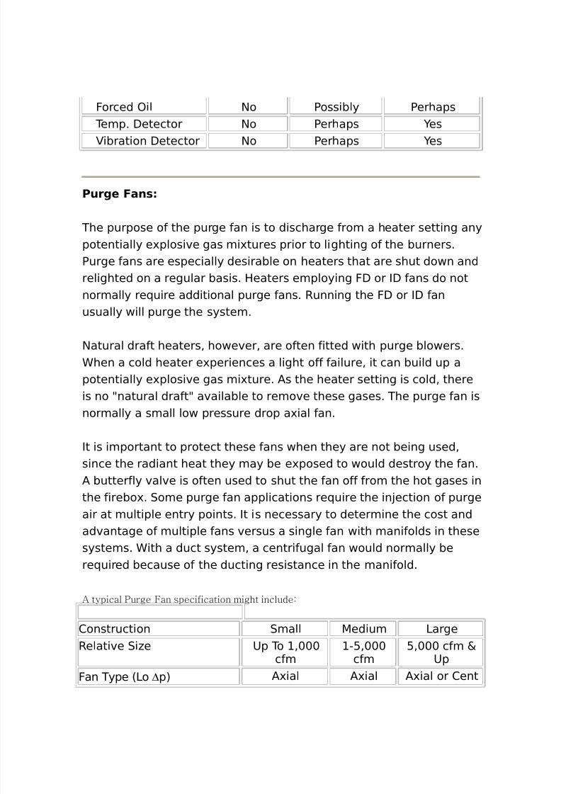
8/16/2019 17730094 Fired Heaters
http://slidepdf.com/reader/full/17730094-fired-heaters 135/141
Forced )il $o Possibly Perhaps Temp. Detector $o Perhaps es
ibration Detector $o Perhaps es
Purge Fan*
The purpose of the purge fan is to discharge from a heater setting anypotentially e'plosive gas mi'tures prior to lighting of the burners.Purge fans are especially desirable on heaters that are shut down and
relighted on a regular basis. Heaters employing FD or ID fans do notnormally re(uire additional purge fans. Running the FD or ID fanusually will purge the system.
$atural draft heaters% however% are often fitted with purge blowers.Chen a cold heater e'periences a light off failure% it can build up apotentially e'plosive gas mi'ture. /s the heater setting is cold% thereis no 9natural draft9 available to remove these gases. The purge fan is
normally a small low pressure drop a'ial fan.
It is important to protect these fans when they are not being used%since the radiant heat they may be e'posed to would destroy the fan./ butterfly valve is often used to shut the fan off from the hot gases inthe firebo'. 0ome purge fan applications re(uire the in!ection of purgeair at multiple entry points. It is necessary to determine the cost andadvantage of multiple fans versus a single fan with manifolds in thesesystems. Cith a duct system% a centrifugal fan would normally bere(uired because of the ducting resistance in the manifold.
% typical ,urge Fan specification might include:
2onstruction 0mall 5edium 3argeRelative 0i#e 8p To %+++
cfm":%+++cfm
:%+++ cfm &8p
Fan Type 63o ∆p7 /'ial /'ial /'ial or 2ent
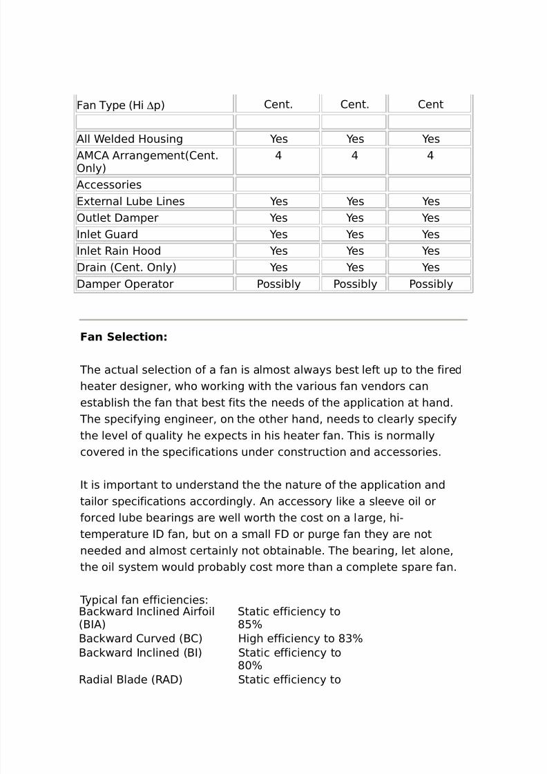
8/16/2019 17730094 Fired Heaters
http://slidepdf.com/reader/full/17730094-fired-heaters 136/141
Fan Type 6Hi ∆p7 2ent. 2ent. 2ent
/ll Celded Housing es es es/52/ /rrangement62ent.)nly7
@ @ @
/ccessories4'ternal 3ube 3ines es es es)utlet Damper es es esInlet 1uard es es esInlet Rain Hood es es es
Drain 62ent. )nly7 es es esDamper )perator Possibly Possibly Possibly
Fan Se/ect)on
The actual selection of a fan is almost always best left up to the firedheater designer% who wor ing with the various fan vendors can
establish the fan that best fits the needs of the application at hand. The specifying engineer% on the other hand% needs to clearly specifythe level of (uality he e'pects in his heater fan. This is normallycovered in the specifications under construction and accessories.
It is important to understand the the nature of the application andtailor specifications accordingly. /n accessory li e a sleeve oil orforced lube bearings are well worth the cost on a large% hi"temperature ID fan% but on a small FD or purge fan they are notneeded and almost certainly not obtainable. The bearing% let alone%the oil system would probably cost more than a complete spare fan.
Typical fan efficienciesL-ac ward Inclined /irfoil6-I/7
0tatic efficiency to*:B
-ac ward 2urved 6-27 High efficiency to *GB-ac ward Inclined 6-I7 0tatic efficiency to
*+B
Radial -lade 6R/D7 0tatic efficiency to
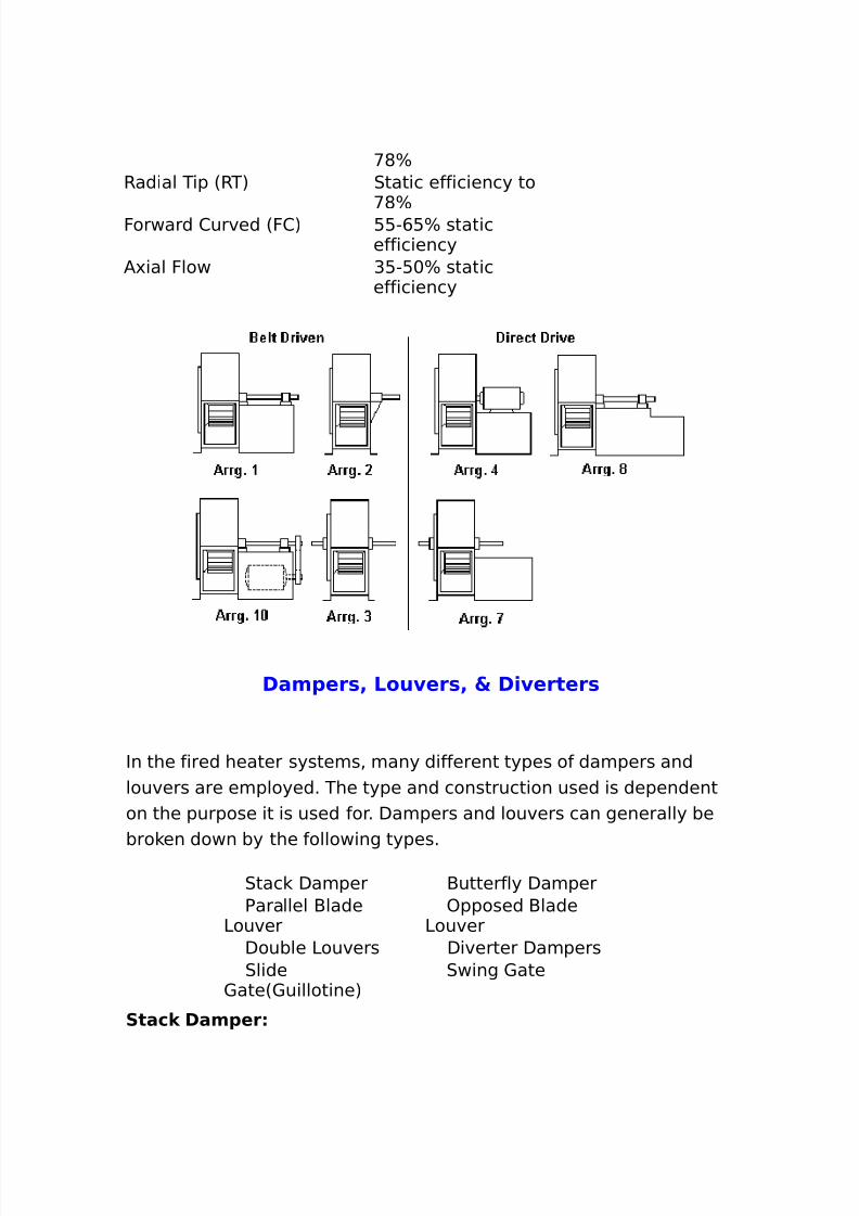
8/16/2019 17730094 Fired Heaters
http://slidepdf.com/reader/full/17730094-fired-heaters 137/141
<*BRadial Tip 6RT7 0tatic efficiency to
<*BForward 2urved 6F27 ::",:B static
efficiency/'ial Flow G:":+B static
efficiency
Dam1er*4 Lou er*4 5 D) erter*
In the fired heater systems% many different types of dampers andlouvers are employed. The type and construction used is dependenton the purpose it is used for. Dampers and louvers can generally bebro en down by the following types.
0tac Damper -utterfly Damper Parallel -lade
3ouver )pposed -lade
3ouver Double 3ouvers Diverter Dampers 0lide
1ate61uillotine7 0wing 1ate
Stac, Dam1er
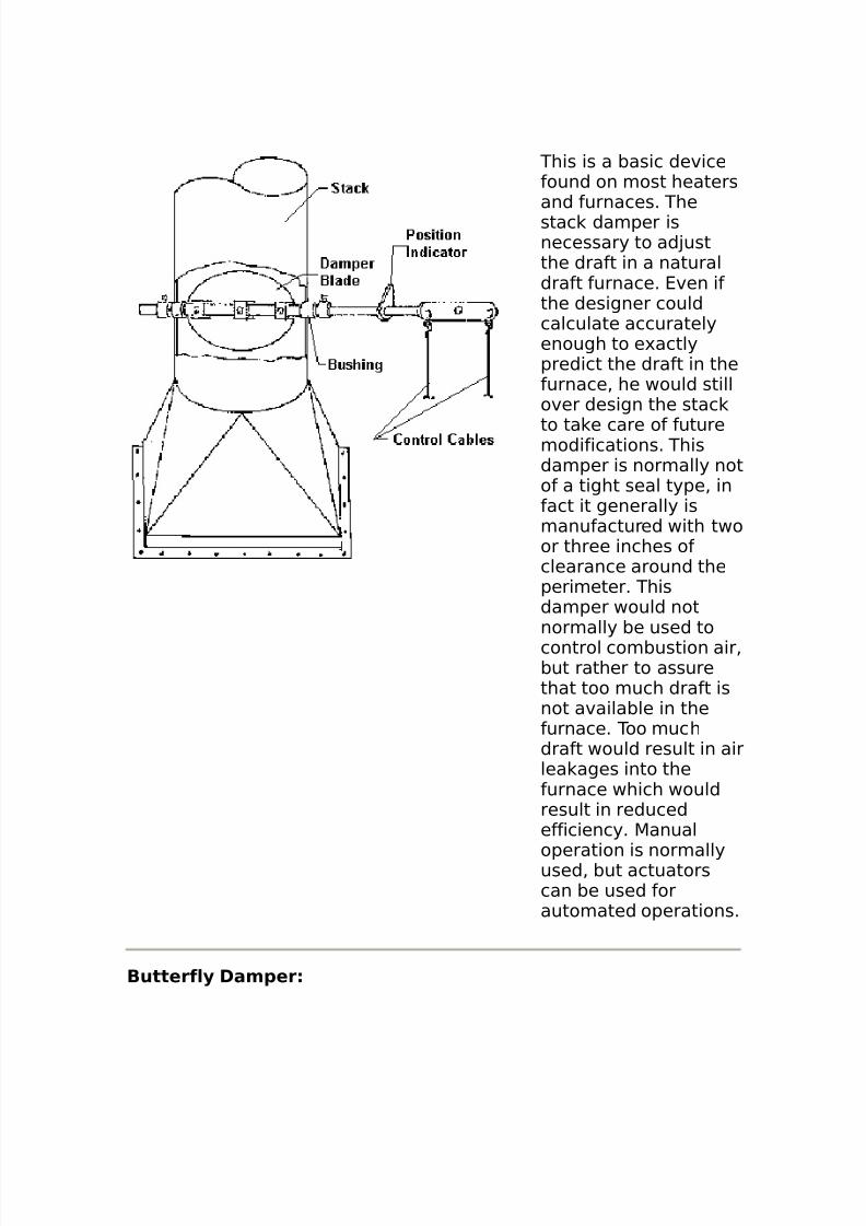
8/16/2019 17730094 Fired Heaters
http://slidepdf.com/reader/full/17730094-fired-heaters 138/141
This is a basic devicefound on most heatersand furnaces. Thestac damper isnecessary to ad!ustthe draft in a naturaldraft furnace. 4ven ifthe designer couldcalculate accuratelyenough to e'actlypredict the draft in thefurnace% he would stillover design the stac
to ta e care of futuremodifications. Thisdamper is normally notof a tight seal type% infact it generally ismanufactured with twoor three inches ofclearance around theperimeter. Thisdamper would notnormally be used tocontrol combustion air%but rather to assurethat too much draft isnot available in thefurnace. Too muchdraft would result in airlea ages into thefurnace which wouldresult in reducedefficiency. 5anual
operation is normallyused% but actuatorscan be used forautomated operations.
Butterf/. Dam1er
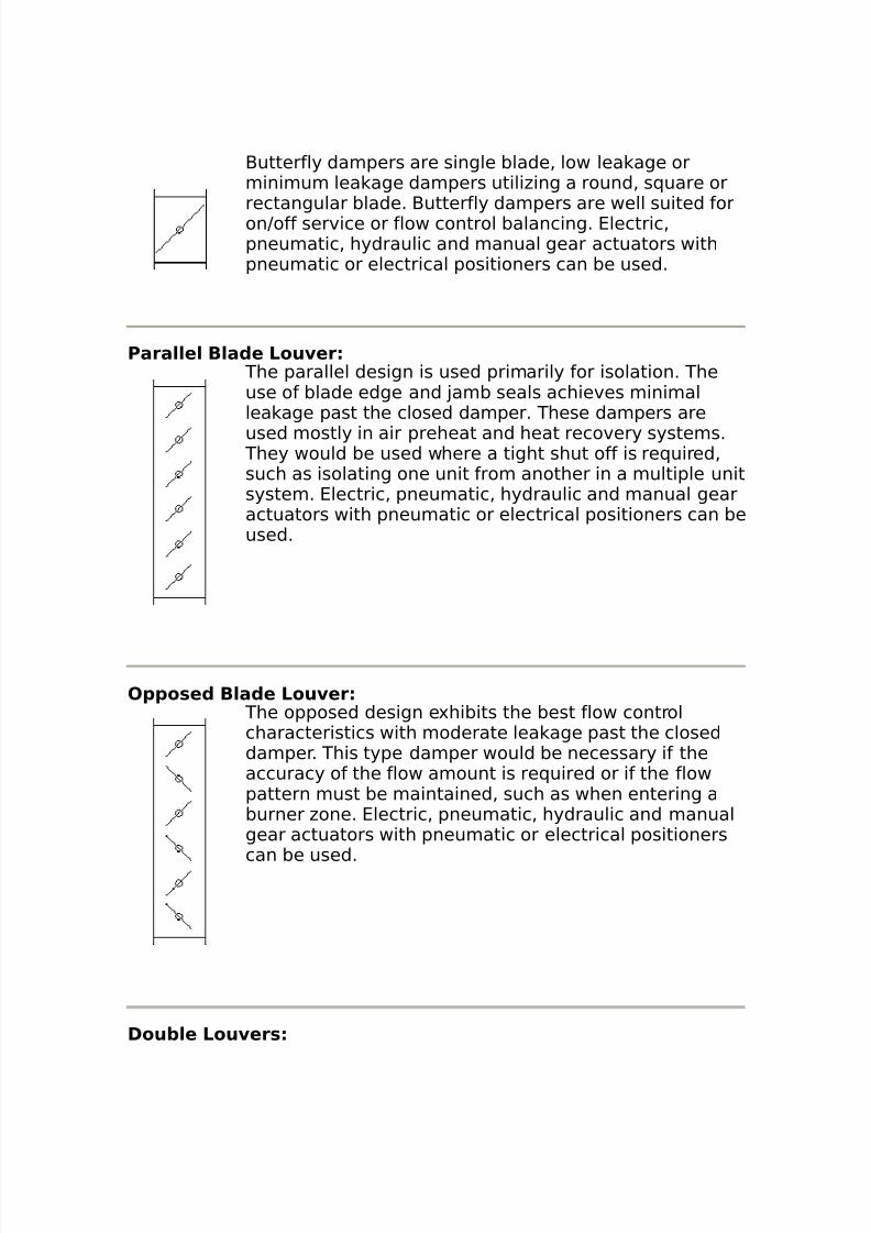
8/16/2019 17730094 Fired Heaters
http://slidepdf.com/reader/full/17730094-fired-heaters 139/141
-utterfly dampers are single blade% low lea age orminimum lea age dampers utili#ing a round% s(uare orrectangular blade. -utterfly dampers are well suited foronJoff service or flow control balancing. 4lectric%pneumatic% hydraulic and manual gear actuators withpneumatic or electrical positioners can be used.
Para//e/ B/a(e Lou er The parallel design is used primarily for isolation. Theuse of blade edge and !amb seals achieves minimallea age past the closed damper. These dampers areused mostly in air preheat and heat recovery systems.
They would be used where a tight shut off is re(uired%such as isolating one unit from another in a multiple unitsystem. 4lectric% pneumatic% hydraulic and manual gearactuators with pneumatic or electrical positioners can beused.
O11o*e( B/a(e Lou er The opposed design e'hibits the best flow controlcharacteristics with moderate lea age past the closeddamper. This type damper would be necessary if theaccuracy of the flow amount is re(uired or if the flowpattern must be maintained% such as when entering aburner #one. 4lectric% pneumatic% hydraulic and manualgear actuators with pneumatic or electrical positioners
can be used.
Dou+/e Lou er*
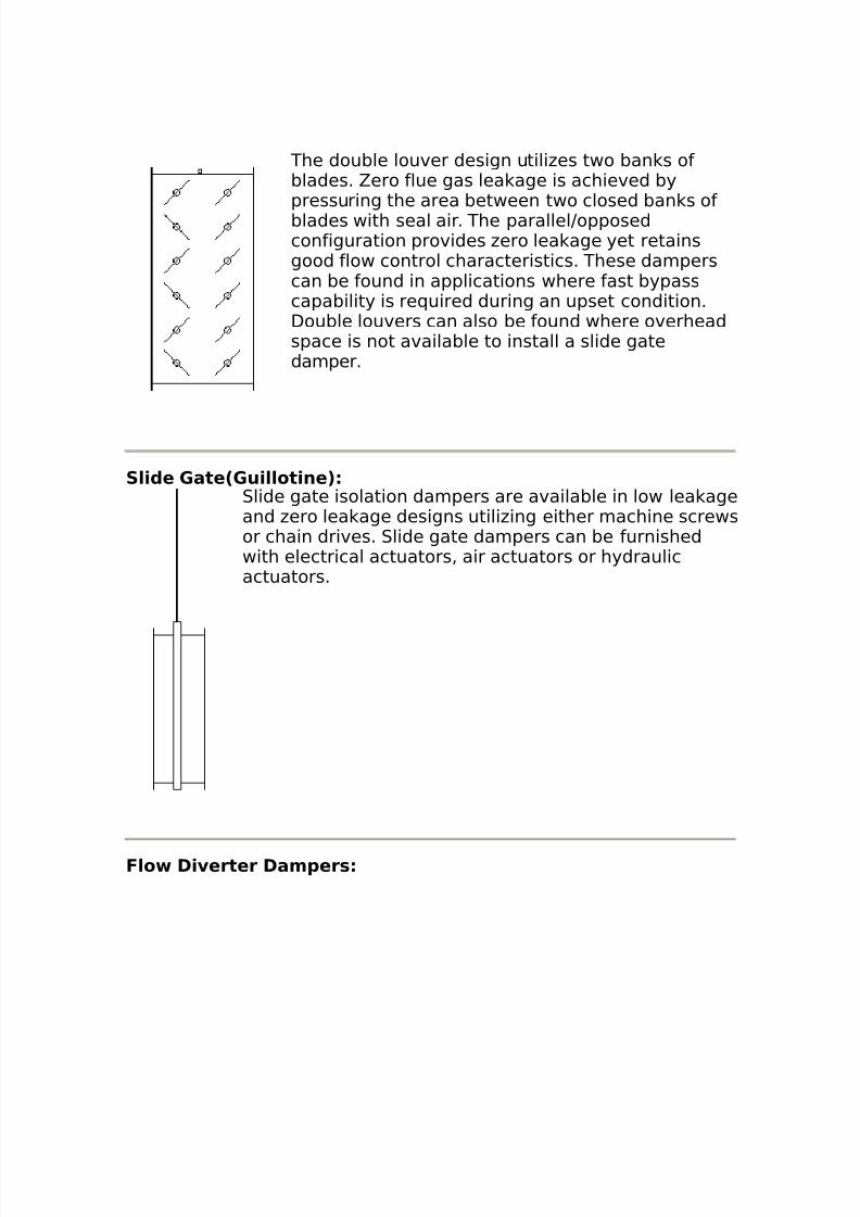
8/16/2019 17730094 Fired Heaters
http://slidepdf.com/reader/full/17730094-fired-heaters 140/141
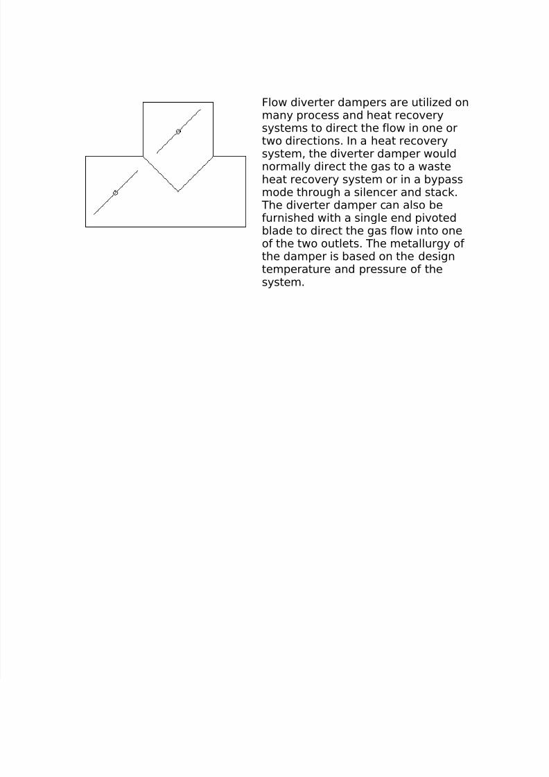
8/16/2019 17730094 Fired Heaters
http://slidepdf.com/reader/full/17730094-fired-heaters 141/141
Flow diverter dampers are utili#ed onmany process and heat recoverysystems to direct the flow in one ortwo directions. In a heat recoverysystem% the diverter damper wouldnormally direct the gas to a wasteheat recovery system or in a bypassmode through a silencer and stac .
The diverter damper can also befurnished with a single end pivotedblade to direct the gas flow into oneof the two outlets. The metallurgy ofthe damper is based on the design
temperature and pressure of thesystem.