171 the seismic design of industrial plants4)0171.pdf · to formulating rational and economic...
TRANSCRIPT

171
THE SEISMIC DESIGN OF INDUSTRIAL PLANTS
(The application of NZS 4203, Code of Practice for General
Structural Design and Design Loadings for Buildings).
Roger D. Evison*, Allan F. Mowat** ABSTRACT:
This paper describes and discusses a practical approach to formulating rational and economic procedures for the seismic design of industrial plants and of petrochemical plants in particular, on the basis of the current New Zealand Loadings Code for Buildings, NZS 4203:1976.
The authors' firm was engaged as consultants for the seismic design (inter alia) of the Ammonia and Urea Plants and offsites for the Kapuni Fertiliser Complex. This paper is a result of that work.and will also be published in 'Transactions of the Institution of Professional Engineers N e w Z e a l a n d 1 .
1. INTRODUCTION:
The New Zealand Code of Practice for General Structural Design and Design Loadings for Buildings, NZS 4203:1976, (1) herein referred to as the Loadings Code, or the Code, is in general use throughout New Zealand.
The seismic design requirements of the Code are relatively complex. The levels of protection which it provides are generally acceptable both socially and financially (2). It was written almost exclusively for building structures and as it lacks p r o vision for many particular requirements of industrial plants its use for such plants encounters a number of difficulties. However, it has been found that the Code is capable of satisfactory application to plants, as described below.
2. BACKGROUND REASONS FOR USING NZS4203 IN PLANT DESIGN
The reasons for adopting the Code as the basis of seismic design in the Kapuni Fertiliser Project were briefly:
a) Compliance with the Code NZS 4203 was mandatory for structures and plant items classified as "buildings" for building permit purposes.
b) Compliance with the Code is the basis of the requirements of N e w Zealand Ministry of Transport, Marine Division, the statutory authority for pressure v e s s e l s .
c) On the advice of the Ministry of Works and Development to the Owners, compliance with NZS 4 203 was made a condition of the m a s t e r contract for design and supply of the plants in this project.
d) The Code is familiar to the NZ design profession.
e) It could be directly applied to many
*Partner, Ian MaCallan and Co., Consulting E n g i n e e r s , Wellington.
**Senior Engineer, Ian MaCallan and Co.
of the frames, buildings, and other basic structural forms in the plant.
These amount to compelling reasons for embracing the task of interpreting and extending the Code so that it could be conveniently applied to the design of plants.
3. SEISMIC DESIGN OF PLANTS AND BUILDINGS COMPARED
Process plant design is a highly specialised and competitive field with well established procedures for dealing with potentially hazardous process conditions such as toxicity, temperature and pressure, conditions which are often very severe. Established practice includes a whole philosophy of risk management which, in many cases, may be subject to the policy of the Owner. In the total international field of process industry the significance of the particular requirements of the N e w Zealand Loadings Code is minimal.
In these circumstances seismic design to New Zealand requirements must be subordinate to the more compelling demands of process and equipment design. It is unrealistic to expect that plant layout, for example, should be dominated by structural problems.
In fact the risk philosophy which underlies the well established acceptance and application of the Loadings Code in building design is very different from that which is appropriate to process plants.
The circumstances of static loads, vertical live loads, occupancy, public contact and interrelation applicable to buildings are generally quite unlike the circumstances in process plants. For example, vertical live loads on plant items are accurately known, whereas they are taken as conservative estimates in buildings.
By recognising this fundamental difference, structural designers will more readily appreciate and avoid compounding the problems of their process design colleagues and hence the additional costs
BULLETIN OF THE NEW ZEALAND NATIONAL SOCIETY FOR EARTHQUAKE ENGINEERING, VOL. 15, NO. 4, DECEMBER 1982

172
imposed by seismic requirements.
The preceding comments are not intended to imply that seismic problems are of secondary importance, but that they must be considered jointly by the Structural and Process engineers as they occur. Normally what may be required is a strengthening modification to a plant item so as to improve its seismic performance without affecting its process function.
It must be emphasised that for plants as well as for buildings seismic design demands not only the appropriate choice and analysis of loads but perhaps even more importantly, good and effective detailing based on a thorough understanding of the performance of the item under seismic loading.
4. THE KAPUNI FERTILISER COMPLEX
The Kapuni Fertiliser Complex comprises a 272 tonne/day ammonia plant, a 470 tonne/day urea plant with granulation, offsites services such as storage vessels, tanks and cooling towers, and a facility for urea bulk storage, dressing, bagging and despatch.
The Principal Contractor for the Complex was Capital Plant International Limited of London. The process plant Subcontractors were Fish Engineering and Construction Inc. of Houston for the ammonia plant and Toyo Engineering Corporation of Tokyo for the urea plant. In their long experience of petrochemical plant design including many for seismic regions, these firms had not hitherto encountered seismic design requirements comparable with the New Zealand Loadings Code.
5. SEISMIC TYPE CLASSIFICATION OF PLANT ITEMS
Most of the structures in the Kapuni Fertiliser Complex were designed using the Capacity Design Method (1), by which specific elements of the structure are designed to yield at the design earthquake level, while all other parts of that structure are designed to be stronger, thus confining any seismic damage to the selected elements. A basic capacity Factor of 1.25 was used.
However plant items of low height and considerable mass that were unable to dissipate energy by ductile yielding, were designed to remain elastic during an earthquake.
Some structures and items of plant in the Complex were found to be amenable to direct application of the Loadings Code. Most, however, required special attention and because of the large and varied number the economic approach was to classify the items in four structural types as follows:
Type A - Tall tubular vessels with ductile yielding anchor bolts.
Type B - Single storey platforms, with ductile yielding in frames or bracing members.
Type C - Low rigid equipment.
Type D - Multilevel structures, with ductile yielding in frame or bracing members.
These types are discussed below in detail.
6. TYPE A - TALL TUBULAR V E S S E L S , STACKS ETC.
The New Zealand Consultants worked closely with engineers of the Principal Contractor and both Subcontractors in developing and applying a seismic design method based on the Loading Code. This involved interchange of senior engineers both ways between New Zealand and Japan, and the United States. This was a rewarding experience for all concerned and was essential to a sound, efficient and economical result.
Some of the vessels in the ammonia plant had already been designed for another site and some had already been fabricated.
Because of the characteristics in which plant components differ from building structures, e.g. in seismic response, risk, structural type, construction and operational factors, it was necessary to interpret the Loadings Code and produce a design method based on it, to cover the differing characteristics.
Examples of the application of the Code to the seismic design of these plants are given in the succeeding sections, w i t h reference to the relevant Clauses and Tables of the Code. First the design process will be outlined for the various types of vessel and plant structure and then the application of the Factors listed in the Code will be discussed.
6.1 Scope
This category comprises tall tubular vessels, stacks etc., usually heavier than 15 tonnes or taller than 5 m e t r e s . Below these limits ductile anchor bolts become too small for practicality.
6.2 Design Philosophy
A ductile energy dissipating element is required at the base of the Type A Item, to conform with the intent of Clause 3.3.2*2 of the Code ( 1 ) .
DUCTILE E L E M E N T
Several methods of providing this ductile element were considered.
One method was the use of a yielding skirt, as developed by Cane (3) and used at the Gas Treatment Plant at Oaonui. This method has the advantage that the yielding element continues to give support both in compression and tension after yielding.

173
However, after yielding it would be impaired and would probably require replacement. This could be a difficult operation in the congestion of a completed plant, as some of these vessels in the Kapuni plant are 30 m high and have an unloaded weight of 135 tonnes. Also the authors concluded that the ultimate moment capacity of a rolled and welded skirt could not be calculated as accurately as that of machined bolts, so that a higher capacity factor would be necessary for the vessel. A further consideration in the choice of ductile element in these items was that when using bolts, no modification work was necessary to certain vessels which had already been designed for another site and in some cases already fabricated.
The anchor bolts for all Type A vessels are designed as the ductile energy dissipating elements, acting in tension only. The bolts are necked down over such a portion of their length that yielding will be confined to that portion and will not occur in the concrete base.
In comparison with the yielding skirt system, the tension-only anchor bolt system has the drawback of varying vessel response after first bolt yield. However, in this case the vessel period would increase, and the subsequent level of force attracted would diminish for the common general shape of the El Centro type response curve.
Other advantages of the ductile anchor bolt system are: that damage can be easily recognised and quickly repaired by replacing strained bolts, without disturbing the vessel, and that the yield point and yield capacity can be established within quite fine limits, permitting a lower Capacity Factor with cost benefits to the,vessel and the foundations.
6.3 Ductile Anchor Bolts - Design Procedure (tension only) Introduction
The allowable stresses specified by the American Society of Mechanical Engineers for pressure vessels were adopted (4) , increased by a factor of 1.33 for earthquake conditions. This is the Alternative Design Method of the Code ( 1 ) . The vessels were checked for various combinations of load i.e. empty, operating, test, wind and earthquake.
The test condition exists when an erected vessel is filled with water and pressure tested, and in some cases exceeds the operating load. The tests may be of three w e e k s 1 duration and may be repeated at intervals throughout the life of the plant. Half earthquake force (0.5E) was used for the test conditions. Foundation sizes were often governed by this test condition because of settlement considerations.
Detailed Methodi
Bending moments and combined stresses were calculated from combinations of the previously mentioned load cases. The
ratio of <X = actual stress
allowable stress
was established at various sections of the vessel as designed. The Alternative Design, or working stress, Method (1) bending moment through the bolts was then divided by the largest value of but not less than 0.8. This has the effect of raising the design bending moment at the bolts, which however could just produce yielding at the weakest section of the vessel.
The design restraining moment is the sum of the bolt forces at their yield stress multiplied by the appropriate lever arms from the neutral axis of the base ring. This moment is equated with the modified design bending moment as above, thus providing a reserve strength capacity as required in the Code, in this case 1.25. The yield stress value of the bolt steel was accurately determined from tests, hence the required bolt area of the necked-down section could be found. A concrete strain of 0.003 was used and the neutral axis' of the bolt group was typically tangential to the inner side of the base flange plate. This generally occurred at approximately 0.95 of the bolt circle diameter.
The length of the necked down section of the bolt was calculated as follows -
The vessel periods for the various load cases were conservatively estimated assuming no ground rotation etc, and by using several response spectra curves, Housner (5), Skinner (6) and Park & B l a k e l e y ( 7 ) , an acceleration Sa was established assuming 2% damping. For this site the curves were adjusted by 2.0 seconds to allow for the flexibility of the soil.
The deflection A u at maximum ductility demand u is defined as
Au = Ay.u
where 0.33 Sa
u = x 2.0 Cd
Ay = elastic deflection of top of vessel under design seismic load.
The factor of 2.0 was included for "one way" energy absorbing system, i.e. bolts in tension only.
The length of the necked down section L was determined from
_ *Au L " OTTTH
where
x = the distance from the outermost bolt to the neutral axis of the bolt ring at yield stress
Au = horizontal deflection at the top of the structure due to seismic forces

174
0.1 = allowed average steel strain
H = height of the vessel.
The length of L should be not less than 300 mm or six bolt diameters.
For anchor bolts designed in tension only the M factor (1) was taken as 0.9.
Wind Dominated Cases:
Wind was the dominant load in some items such as some tall, light vessels with large projected area.
In these circumstances the bolts were designed as previously described, but using the bending moment due, to wind. The earthquake bending moment or force can increase until it fully utilises the bolt strength that is available in the ductile energy absorbing element.
6.4 Bolt Material Specification:
Requirements for the material for these anchors bolts are:
- High ductility
- Low yield strength to allow bolts to be of a reasonable size
- Yield strength of consistent value
- Reasonable machinability.
The desirable yield characteristics preclude the use of high sulphur, high machining quality steels.
EQUIPMENT A T ONE L E V E L
EQUIPMENT AT ONE LEVEL
PORTAL OR X BRACING LIGHTWEIGHT STRUCTURE X BRACED
STEEL OR CONCRETE PORTAL FORMS
Steels conforming to NZS 3402P 1973, Grade 275 and AS 1204/250 were finally chosen after testing of several finished bolts. These materials gave consistent low yield values and exhibited minimum values of elongation and izod impact tests of 27% and 40ftlb (54J) respectively.
b) Horizontally Supported Vessels Vertical Cantilevers (Ductile hinges at x)
Good quality, score-free machining of the bolts is essential. Some of the test samples were diagonally scratched and when tested gave erratic tensile results.
7. TYPE B SINGLE STOREY PLATFORMS SUPPORTING EQUIPMENT
7.1 Scope
This design procedure is recommended for platforms supporting one or more items o f equipment at one basic platform level; the supporting structure in effect, acts a s a single storey building.
7.2 Examples
a) Frames (Ductile yielding at x) To obtain ductile bending, — ,< 4. B

175
Consequently the foundations may need to be set well down into the ground.
In elevation B, heat expansion may require one end sliding, so that the whole longitudinal Cd force acts at one end of the item of equipment.
7.3 Design Philosophy
These structures are analysed as conventional one-storey frames, the forces in their members being calculated by conventional elastic m e t h o d s . The energy dissipating elements are designed closely to these forces•
For example, in the case of cross-braced frames, the braces are necked down over a suitable short length to ensure controlled ductile yielding, design loads for all other parts of the structure being increased by a capacity factor of 1.25.
7.4 Ductile Bracing Examples
TYPE C - SHORT RIGID EQUIPMENT, TANKS ETC
8.1 Scope
This design procedure is recommended for equipment and structures that are short, rigid and inherently strong; where it is difficult to form a reliable "ductile energy dissipating element" within the equipment, its support structure or the foundation parts.
8.2 Examples
BRACING ROD
L / d > 6
VERY STRONG MEMBERS
BRACING A N G L E
BOTH FLANGES MAY BE NOTCHED
No limitation of height or size was placed on these structures.
176
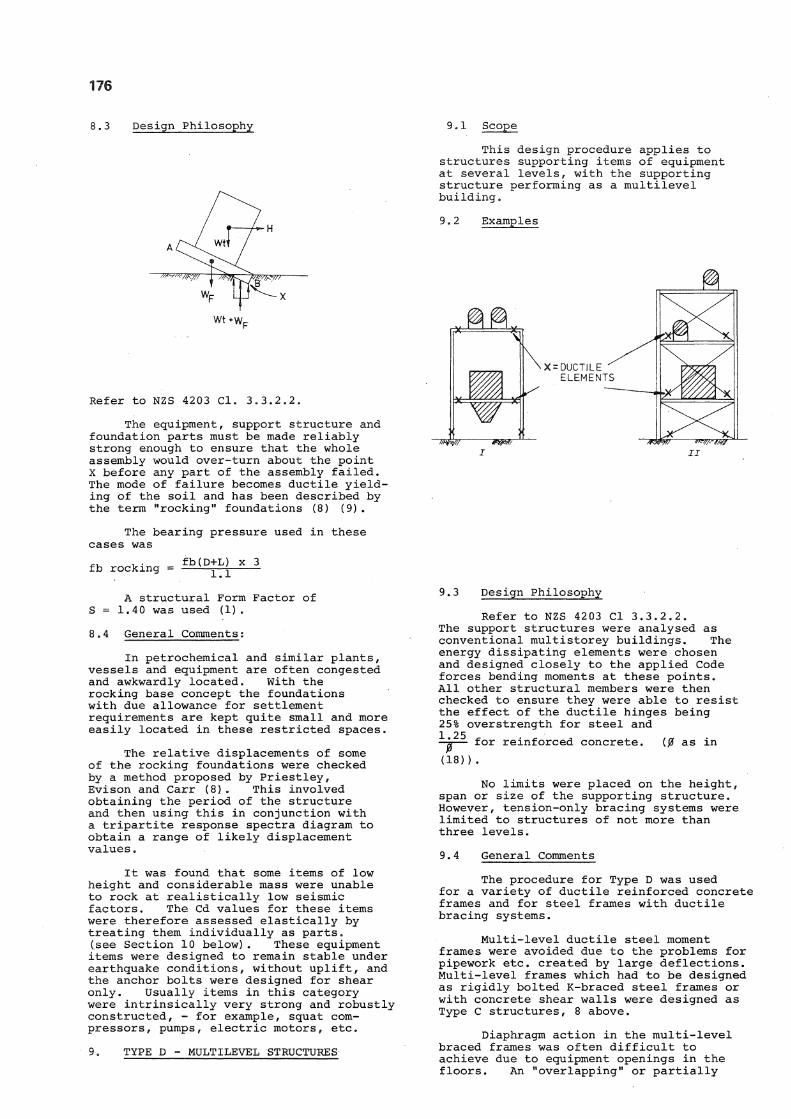
8.3 Design Philosophy
w t * w F
Refer to NZS 4203 Cl. 3.3.2.2.
The equipment, support structure and foundation parts must be made reliably strong enough to ensure that the whole assembly would over-turn about the point X before any part of the assembly failed. The mode of failure becomes ductile yielding of the soil and has been described by the term "rocking" foundations (8) (9).
The bearing pressure used in these cases was _ , . fb(D+L) x 3 fb rocking = ^ £
A structural Form Factor of S = 1.40 was used (1).
8.4 General Comments:
In petrochemical and similar plants, vessels and equipment are often congested and awkwardly located. With the rocking base concept the foundations with due allowance for settlement requirements are kept quite small and more easily located in these restricted spaces.
The relative displacements of some of the rocking foundations were checked by a method proposed by Priestley, Evison and Carr (8). This involved obtaining the period of the structure and then using this in conjunction with a tripartite response spectra diagram to obtain a range of likely displacement values.
It was found that some items of low height and considerable mass were unable to rock at realistically low seismic factors. The Cd values for these items were therefore assessed elastically by treating them individually as parts. (see Section 10 b e l o w ) . These equipment items were designed to remain stable under earthquake conditions, without uplift, and the anchor bolts were designed for shear only. Usually items in this category were intrinsically very strong and robustly constructed, - for example, squat compressors, pumps , electric motors, etc.
9. TYPE D - MULTILEVEL STRUCTURES
9.1 Scope
This design procedure applies to structures supporting items of equipment at several levels, with the supporting structure performing as a multilevel building.
9.2 Examples
I
9.3 Design Philosophy
Refer to NZS 4203 Cl 3.3.2.2. The support structures were analysed as conventional multistorey buildings. The energy dissipating elements were chosen and designed closely to the applied Code forces bending moments at these points. All other structural members were then checked to ensure they were able to resist the effect of the ductile hinges being 25% overstrength for steel and 1 25
— for reinforced concrete. (j2f as in (18)).
No limits were placed on the height, span or size of the supporting structure. However, tension-only bracing systems were limited to structures of not m o r e than three levels.
9.4 General Comments
The procedure for Type D was used for a variety of ductile reinforced concrete frames and for steel frames with ductile bracing systems.
Multi-level ductile steel moment frames were avoided due to the problems for pipework etc. created by large deflections. Multi-level frames which had to be designed as rigidly bolted K-braced steel frames or with concrete shear walls were designed as Type C structures, 8 above.
Diaphragm action in the multi-level braced frames was often difficult to achieve due to equipment openings in the floors. An "overlapping" or partially

177
redundant bracing system was used to overcome this problem.
High Strength Friction Grip (HSFG) bolted angle type horizontal bracing was normally used, although welded chequer plate flooring served as bracing in some circumstances . A considerable amount of structural steelwork on this project was detailed for HSFG bolted joints. This method is convenient for plant procurement, in which the structures are often supplied in packages, fabricated by one contractor and erected by another,
Throughout the project the analysis of seismic loading was done by the Equivalent Static Force Method (1) as realistic and economic of engineering costs. As a check on this method one selected Type A vessel was subjected to a spectral modal analysis. This showed that the base shear was 10% lower and the Code 2 0% load applied at the top was in reality spread across the upper third. Hence the design shears and bending moments used were a little high, by a factor which justified the method used.
The authors recommend the Static Force Method, with appropriate use of check spectral modal analysis.
10. PARTS OF STRUCTURES
It is well understood that concentrations of mass attached to an elastic structure may attract to it seismic loads greater than those generated by its own response.
10.1 The concept of multiplying factors for the seismic forces on Parts and
Portions of Buildings is an important component of the Loadings Code and is appropriate to the case of plants. However, the specific provisions of Table 9 (1) do not adequately cover the large and varied number of items of equipment that are supported on various structures and vessels in these plants.
The method of obtaining Cp, the Seismic Coefficient for Parts was therefore extended as follows.
ATTACHED PARTS
N o t e : Kp = 1.5 for one storey structures and for items located at ground or foundation level.
Kp was not greater than 2.5 for any of the items on this project.
10.3 Risk Factor of Part - Rp
The Risk Factor R of the supporting structure should be the R applicable to the highest risk item supported.
If an item is relatively small and of a higher general risk, special consideration can be given to this item so as to avoid an unnecessary overstrength capacity in other lower risk items.
10.4 Structural Type Factor - Sp
The present Sp values as shown in Table 8 make no reference to plant items and a table of Sp values needs to be developed for the various vessel types in a plant. The following values chosen for the Kapuni Project varied from 1.0 to 2.0 and depended on the number of fixing b o l t s , the shape, form and inherent ductility of the plant item.
10.2 Calculated Assessment of Cp
Cd = C.I.M.S.R., as recommended in the Design Basis Types A,B,C and D in Sections 6 to 9 above, where R = the Risk Factor applicable to the highest risk item of equipment supported by the structure; and
The seismic coefficient for Parts = Cp = Kp. Rp. Cd. Sp. Mp.
The Position factor Kp = 1.5 Kx 1.50.

178
RECOMMENDED VALUES OF Sp for items of equipment
not included in NZS 4203 Table 8.
Item Description of item of equipment Sp
Members and equipment distributing seismic
forces, detailed for ductility, e.g.
Pedestrian ladders, bridges, platforms,
catwalks etc., pipes, tubes and duct in
structural steel.
1.0
Reduced ductility
0
1 4 T # More than 6 base fixing bolts
6 or less base fixing bolts
Thin wall tanks with integral floor and roof, containing liquids.
8 or more fixing bolts required Sloshing effects must be added.
1.2
1.4
1.2
1.4
2.0
Limited ductility
Motors, pumps compressors and solid items
which have rigid bases and fixing cleats,
where fixing bolts provide the only
available ductility. More than 6 base
fixing bolts:
6 or less base fixing bolts:
1.5
1.7

179
Sp values were chosen to reflect the potential seismic performance of the particular vessel or piece of equipment in question. The shape, form, method of fixing and ability to dissipate energy at a number of places all require to be considered.
Particular care has to be taken to ensure that the method of attaching thin-walled vessels, hoppers etc. to their support structures transfers the calculated seismic force in a satisfactory manner. This is one of a number of issues which come into a transitional area between the Mechanical and Structural disciplines, affecting the detailing of the plant items as well as the structure.
10.6 Tabulated Values of Cp
The following tabulated values of Cp for items of equipment are recommended as an alternative to the calculated assessment of Cp above. The tabulated values of Cp are based upon Mp = 0.8, and must be adjusted where necessary for less ductile materials (10.5 a b o v e ) .
C d = C.I.M.S.R.
The multiplying factors in the Code equation for horizontal seismic force were applied in the Kapuni project as discussed below.
11. STRUCTURAL TYPE FACTOR - S (1)
10.5 Material Factor for Parts
Mp was as given in NZS 4203, Table 6.
Note that M = 0.8 for Structural Steel refers to the ductile grades of steel used for buildings in New Zealand. A larger value of M must be used for less ductile grades of steel and materials such as cast iron. As a general guide it is recommended for grey cast iron, ceramics and similar brittle materials, that M = 2.0.
This factor provides for the effect of seismic loading on the particular type of structure. S values were selected in the range of 0.8 to 2.0 in accordance with Table 5 of the Loadings Code. For Type C structures as in 8 above, which are not covered in the Code, S was taken at 1.40.
12. IMPORTANCE FACTOR AND RISK FACTOR
The Loadings Code uses these two factors but is not entirely explicit in the terms applied to them, leaving some room for confusion. Elms draws attention to this (10) and recommends
PART attached to 1.0 1.2 1.5 2.0
Attached to a one storey support
structure having ductile frames
(see Type B above, Section 7) 0.20 0.24 0.30 0.4
Attached to a one storey support
structure having diagonally
braced frames
(see Type B, Section 7) 0.35 0.42 0.53 0.70
*Attached to a multi-storey support
structure having ductile frames
(see Type D Section 8) or attached
to items of equipment that are self
supporting structures (See Type A
Section G & C, Section 8) 0.35S 0.42S 0.53S 0.70S
Attached to a foundation supporting
other items such as equipment or
support structures; and not being
Type A or C. 0.5 0.6 0.75 1.0
*These tabulated values must be multiplied by the appropriate S value for the support structure, Refer NZS 4203 Table 5.

180
that one composite factor be used as also do others, e.g. (17) .
In the authors' opinion it is helpful, particularly in the case of plants, to provide distinct and separate factors to cover two types of consequence of seismic damage. These factors may be described as:
12.1 Social or economic importance of the facility, including its effectiveness
immediately after a destructive earthquake; e.g. "lifeline" services, and operations very sensitive to financial loss.
12.2 Risk of immediate, serious injury to life or the environment by damage to
the facility; e.g. by release of toxic substances or by collapse on to a large number of people.
The Loadings Code terms these factors respectively Importance Factor and Risk Factor, and their definitions should be clarified in future amendments.
The above concept of Risk Factor is well established in seismic design codes generally, but the separate concept of Importance Factor in the economic or functional sense appears to be less usual, though it appears in the New Zealand Loadings Code and in some current Japanese work (11).
13. IMPORTANCE FACTOR - I (1)
In its economic aspect the value allotted to this factor must be principally a matter for the Owner's policy. The question of public or private ownership per se is irrelevant to plants in the authors' opinion. See Table 4 ( 1 ) , also (11) .
The Fertiliser Complex was considered to be a normal commercial operation with a life of 25 years and a factor of I = 1.0 was used.
The Code in Table 4 lists a range of values from 1 to 1.6 to cover the social aspect of this factor.
14. RISK FACTOR - R (1)
Selection of appropriate values of Risk Factor for plants necessitates a thorough study of all the plant items including pipework.
Some of the aspects to be examined are noted below.
14.1 General Considerations
(a) The level of plant operator and maintenance staff safety training and emergency procedures.
(b) The degree of access to the plant by outside personnel not trained in the plant, and by the general public.
(c) The establishment within the plant of safety zones and escape routes:
(d) The total number of persons within the danger zone at any one time (In Japan the highest rating of this aspect is suggested at 100 persons (11). Another approach considers the clearance from communal occupancy (12)).
(e) Confinement within a building.
(f) The magnitude, duration and nature of a toxic emission resulting from rupture due to excess seismic loading (12) (13) .
(g) Countermeasures to contain toxic emissions within the plant (13) .
14.2 Examples of the Risk Factors adopted for this plant were as follows:
VESSEL
Reactor
Ammonia Reservoir
High Pressure Absorber
High Pressure Cooler
High Pressure Decomposer
All other items
CONTAINED AMMONIA RISK FACTOR
16 tonnes
8 t
1 t
1.5 (a)
2.0 '(b)
1.2
0.2 t or less 1.0
Ammonia pipelines and equipment from battery limits to Ammonia Feed Pumps, to Reservoir, and from Reservoir to Vacuum Absorber and other vessels contributing recycled ammonia, including all relevant supporting structures. 2.0
Ammonia Storage
Storage Bullets 150 t each 3.0
(Note: This corresponds with the maximum risk contemplated by the Code (1))
Ammonia Plant
Ammonia Letdown Drum4.1 t 1.5
Ammonia Absorber (Connected to above) 1.5
Ammonia Stripper Reflux Drum 0.7 t
Refrigerant Suction Drum 0.6 t
All other items
Steam Pressure Plant
Pipes and Valves
Steam Pressure Vessels within Buildings
1.2
1.2
1.0
1.0
Rp - 2.0 All other steam pressure vessels 1.5
(a) Reactor Ammonia release would be limited to its contents

181
(16 tonnes) by a back-pressure valve on the outlet.
(b) Ammonia Reservoir - The contents could be released
at failures in connected pipelines and vessels over much of the plant area.
15. LIMITATION ON TOTAL SEISMIC FACTOR
The Loadings Code provides that, in general, the value of R x S may be limited to 3.6. This relief may possibly be inappropriate in some cases where high R i s k is combined with structural types of low seismic performance.
On the other hand there are good grounds for considering a maximum limit for I x R x S in cases where I is greater than unity.
16. SPECIAL STUDIES (1)
Reference is made in the Loadings Code to Special Studies being required for unusual structural cases. A Special Study should involve a careful examination of Risk and Structural Form of the plant items in question, and should be done in conjunction with the plant process engineers.
The use of Cost/Benefit studies has been suggested as an example of Special Studies. Although such studies may imply thoroughness they are unlikely to be realistic as a general approach in the design of the multiplicity of items in even the simplest petrochemical plant.
17. MISCELLANEOUS PLANT ITEMS
17.1 Pipework
The pipe lines were computer designed by the process plant designers to conform with N . Z . Ministry of Transport Marine Dept. requirements for Dead, Live, Wind, Mean Wind and Seismic Loads.
Factors considered were:
a) Stresses arising from circumferential pressure.
b) Bending stresses caused by support conditions, e.g. corners etc.
c) Differential movement due to expansion/contraction and earthquake effects.
The pipework was classified as "Parts" and the appropriate Cp factors were derived as described above.
The detailing of the pipework/vessel joints was the responsibility of the vessel vendors, whose work was checked by Lloyds of London.
The nozzle/vessel connections were designed to remain elastic under earthquake conditions. Where necessary added protection was provided by vertical single pier cantilever pipe supports as well as by the normal expansion loops and bends. Pipes that entered the main pipe racks at rightangles were detailed so as to allow
free lateral movement at these points. The lateral expansion forces were not considered to act concurrently with earthquake loads.
17 .2 Piperacks
Two different types of piperack have been used;
a) fully moment resisting frames in both longitudinal and transverse directions
b) moment resisting lateral frames, braced in the longitudinal direction.
Both systems had longitudinal breaks for expansion, with the longitudinal moment frames being very much m o r e flexible than the ductile braced system.
Pipework designers may be reluctant to provide sufficient connections, either fixed or sliding, between the pipes and the supporting frames. Co-operation is needed here between the Process and* Structural engineers to ensure that the assumed design loads do in fact occur at points where they were intended.
Suspending pipe runs on hangers reduces the problems of seismic loading.
On long pipe runs occasional restraints are required against lateral displacement under seismic loading.
The foundations for the piperacks were of a simple strip footing type in two directions. This system was chosen to provide low bearing stresses and provide base fixity where needed, and it proved to be very economical.
17.3 Storage Tankst
Many of the smaller storage and process tanks in the plant were inherently strong, usually with plate steel roofs. Depending on their location, some tanks were designed as parts using an Sp factor of 2.0.
The sloshing effect was considered in the designs but the effect was minor for the smaller tanks, becoming more significant in the design of tanks of diameter greater than 12m.
17.4 Horizontally Supported Pressure Vessels
It is usual with this type of vessel to have sliding supports at one end for expansion purposes. This requirement places all the longitudinal earthquake forces at one support leg. This force was transferred from the vessel to the foundations by means of steel supports extending to mid-height thus avoiding high local bending stresses in the shell plates. Several vendors were required to modify their designs accordingly.

182
17.5 Mechanical Equipment
Some comment should be made on the subject of such plant items as pumps, compressors and the like, although in the Kapuni Plant these items were outside the Consultant's responsibilities. In the construction of this type of plant the provisions for normal service conditions such as temperature, pressure, vibration and installation stresses normally result in inherent strength against seismic loads as well.
In the overall design of a process plant consideration should be given to such obvious matters as secure foundations and anchorage, safety against falling or dislodged material, and avoidable seismic loads imparted by rigidly connected plant items.
Where special measures are considered necessary to check the security of critical items, it is established practice for this to be done by analysis or by mechanical test by the makers or a verifying authority.
17.6 Vibrating Plant
Plant supporting structures subject to vibrations by heavy plant such as compressors are likely to be best in reinforced concrete and should not be designed as Type C structures as in 8 above.
17.7 High and Low Operating Temperatures
Yield stresses considered in design must be applicable at operating temperatures.
18. SETTLEMENT AND DEFLECTION
Equipment and process design requirements may impose constraints on settlement and deflection which call for special consideration in the light of seismic loadings.
For example in the Kapuni plant the following constraints were laid down for settlement and deflection induced by settlement:
19. GENERAL COMMENTS ON THE LOADINGS CODE
total settlement of any foundation
maximum inclination - steel structure - concrete structure - vessel
pipeline supports, maximum inclination due to differential settlement
20 mm
6/1000 3/1000 1/1000
1/3000
In observing such requirements it is necessary to consider ground motion under seismic loading, as well as predicted settlements.
In this project a settlement monitoring programme is being followed from the time of c a s t i n g foundations, the result being compared with predictions as a guide to designed performance under both static ancl s e i s m i c l o a d s .
These comments are offered as pertinent to future work on the Loadings Code, to which amendments are in course of preparation.
19.1 Presentation
It was noted that the Code is relatively complex. This applies both to the detail of the requirements and to the manner of presentation. The authors have been reminded of this by the reactions of engineers familiar with plant design in other seismic regions, notably in Japan and the United States. When the Code had been explained there was ready acceptance of the methods for its application to plants as described in this paper.
19.2 Complexity
Compared with New Zealand, both Japan and USA have much more extensive data related to seismic loading, and both have at risk very much larger populations and very much ' greater property in industrial plants. Requirements for the seismic design of plants in both countries are appreciably simpler and less demanding of engineer time (12) .
The Chairman of the Japanese committee drafting guidelines for the seismic design of petrochemical plants has said that those guidelines are intended:
"to protect plant components from earthquake damage,"
"to prevent hazards to the public" that they
and
"endeavour to simplify and make the procedure of seismic design easier as much as possible":
"and that emphasis is given jointly to safety and to economy" (13) . The authors have taken this into account in the work described in this paper.
19.3 Seismic Zoning (14), (15)
The seismic zones provided in the Code in Figure 4 are based on about 50 years of accurate magnitude and location records and a further 90 years of limited descriptive information. It is widely held that this is insufficient support for zoning. It bears no relation to the recorded data upon which Japan and North America have been zoned. (Nevertheless Niigata was placed in a low risk zone before the disastrous earthquake of 1 9 6 4 ) .
The weaknesses in the zoning map, Fig. 4 (1) are evident in the original Commentary (16), since then however it has remained unchanged. A token change is now suggested by the Ministry of Works and Development (17). It is recommended that the zoning provisions of the Code be critically considered in the seismic design of important plants.

183
20. ALTERNATIVE APPROACHES TO SEISMIC DESIGN
Recently there has been a trend to apply, in New Zealand, the statistical or return period approach to determine the basic coefficients to be used in seismic design (14, 15, 17) . There is logic in this approach to determining probable earthquake magnitudes for regions where the data cover a sufficient period of time. However, the New Zealand data base as noted in 19.3 above is too short a time for this purpose. Periods of seismic activity and quiescence are known to occur and it is impossible to gauge the activity level of the period to which the limited data base belongs.
In using this statistical approach to establish XXX zoning boundaries, it should be remembered that New Zealand is a relatively small country, and that strong earthquake effects can be felt 100 km away from the epicentre. A more uniform zoning would seem to be appropriate as has been consistently suggested for many years. In fact there is support for a Zone A for the whole of the South Island and most of the North Island, with Zone B for the rest of the North Island.
The statistical or return period approach, even with its above shortcomings for New Zealand, has some value when assessing earthquake magnitudes and distribution. However, the authors question the recommendations to use it as the sole basis for seismic design. As proposed, it eliminates the use of Risk Factor and substitutes return periods in a range which is extrapolated far beyond the limited data base.
The authors consider that the Risk Factor method is better suited to the exercise of engineering judgement and to allowing for individual risk and hence to build up a better general assessment of the earthquake forces which are appropriate for each particular case. See 14.1 above.
Further, the base coefficients as existing in the Code are considered to offer an adequate degree of protection to life and property. It has been suggested by Hatrick (2) that to arbitrarily increase the basic design forces offers only a very small increase in protection against structural "failure".
21. CONCLUSIONS
Experience in seismic design of the Kapuni Fertiliser plant leads to the following conclusions in summary:
1. The Loadings Code, NZS 4203, is capable of satisfactory application to the seismic design of plants, as above.
2. It is recommended that future amendments to the Loadings Code include provisions for plants.
3. In future amendments attention should be paid to the virtue of simplicity both in detailed requirements and in presentation, including clarity of language.
ACKNOWLEDGEMENTS;
The authors gratefully acknowledge the co-operation of Capital Plant International Limited, Fish Engineering and Construction Inc. and Toyo Engineering Corporation, the valuable contribution of R.C. Amos of Bruce-Smith, Chapman and Amos and the comments of correspondents to 'New Zealand E n g i n e e r i n g 8 upon the a u t h o r s 1 introductory paper published in that journal in May 1981.
REFERENCES:
1. NZS 4203:1976 Code of Practice for General Structural Design and Design Loadings for Buildings, Standards Association of New Zealand, Wellington 1976.
2. Hatrick, A.V."Seismic Design and Risk! Bulletin of the New Zealand National Society for Earthquake Engineering, Volume 13, March 1980.
3. Cane, F . J . u T h e Effects of Earthquake Loads on the Design of Pressure, Vessel Shells', Conference on Engineering Design for Earthquake Environment, November 1978, I Mech E.
4. American Society of Mechanical Engineers. Boiler and Pressure Vessel Code Section VIII Division I.
5. Weigel, R.L. editor. "Earthquake Engineering" Prentice-Hall 1970.
6. Glogau, 0. paper "N.Z. Loadings Code Philosophy". N . Z . Loadings Code Seminar, Victoria University, 1975.
7. Park, R. and BlakeleyR.W.G., "Seismic Design of Bridges" N . Z . N.R.B, Road Research Unit Bulletin 43 :1980 .
8. Priestley, M.J.N.; Evison R.J. and Carr A.J.,"Seismic Response of Structures free to Rock on their Foundations". Bulletin N. Z . Nat. Soc. Earthquake Eng. Volume 11, N o . 3 September 1978.
9. Taylor, P.W. and Williams R.L., "Foundations for Capacity Designed Structures'. Bulletin N. Z. Nat. S o c Earthquake Eng. Volume 12 r No. 2, June 1979.
10. Elms, D.G., ^Reliability - Based Risk Factors!! Bulletin N. Z . Nat. Soc. Earthquake Eng. Volume 13, March 1980.
11. Shibata, H. and Tsuchiya, M. "Fundamental Concept of Aseismic Design of Earthquake Resistant Lifeline Svsterns and Industrial F a c i l i t i e s P r o c . Lifeline Earthquake Engineering Conference - ASCE 1977.
12. Draft of A n t i - Earthquake Design Code for High-Pressure Gas Manufacturing Facilities, 1980. Ministry of International Trade and Industries, Japan. (Pers. C o m m ) .
13. Udoguchi, T.,"Aseismic Design of Plant Components in Power Generation and Petrochemical Industries " Proc.

184
Third International Conference on Pressure Vessel Technology, 1977, A . S . M . E .
14. Smith, W.D."Earthquake Risk in New Zealand: Statistical Estimates. New Zealand Journal of Geology and Geophysics Volume 21, N o . 3 (1978): 313-327.
15. Smith, W.D.,"Spatial Distribution of Felt Intensities for N e w Zealand Earthquakes" New Zealand Journal of Geology and Geophysics, Volume 21, No. 3 (1978).293-311.
16. Commentary on Chapter 8 of NZSS 1900. New Zealand Standards Institute. 1965.
17. Recommendations for the Seismic Design of Petrochemical Plants, Ministry of Works and Development, March 1981.
18. "Building Code Requirements for Reinforced Concrete" ACI 318-77.