17 eec-iv monitor intermittent fault diagnosis 17 - eec-iv...monitor intermittent fault diagnosis...
TRANSCRIPT
SECTION 17
EEC-IV Monitor Intermittent Fault Diagnosis
Contents Introduction 17-1
Diagnostic Flow Chart 17-3
Step 1 Visual Check Vehicle Preparation 17-4
Step 2 Equipment Set-up 17-5
Step 3 Power and Ground Tests 17-6
Step 4 Symptom Analysis 17-10
Step 5 Road Test 17-11
Step 6 Analyzing Data 17-13
Appendix
Description and Installation of EEC-IV Monitor 17-17
Description and Installation of EEC-IV Recorder 17-22
Methods of EEC-IV Monitor Measurements 17-26
Copyright copy 1990 Ford Motor Co wwwtechcapricom
Copyright copy 1990 Ford Motor Co wwwtechcapricom
EEC~IV Monitor Intermittent Fault Diagnosis 17~1
Introduction All
Engines
DEFINING INTERMITTENT DRIVEABILITY SYMPTOMS
The EEC-IV Monitor and the EEC-IV Monitor Recorder are useful tools for diagnosing intermittent driveability symptoms which are unable to be resolved through the diagnostics in Section 16 Pinpoint Testing This section supports diagnostic procedures and data using the Monitor and Recorder in a symptom-oriented manner
By definition an intermittent is a randomly occurring drive symptom for which no hard codes (KOEO KOER) are revealed by the SUPER STAR II tester Often the Quick Test results in Pass Codes while the drive symptom still exists Other results such as Continuous Memory Codes will also be used in this section
Before proceeding with the following procedure be sure that
bull Customary mechanical system tests and inspections reveal nothing (Remember mechanical component problems can make a g00d EEC system react abnormally)
bull Quick Test (Section 15) and associated Pinpoint Test diagnostics (Section 16) have been completed but the symptom is still occurring
bull Review of Ford Technical Service Bulletins (TSBs) and inquiry into OASIS turns up no applicable articles
PURPOSE OF THIS SECTION
The Monitor and Recorder function as a window into the EEC system Through this window the user is able to view the same sensor and actuator values which the EEC processor uses to make decisions about engine performance The Monitor displays these values for both static (Key Off KOEO) and dynamic conditions (KOER) The advantage of the Recorder is the ability to take a snapshot of selected EEC signals which can be stored and reviewed later
NOTE From here forward the EEC~IV Monitor and EEC-IV Monitor Recorder will be referred to as Monitor and Recorder respectively
Copyright copy 1990 Ford Motor Co wwwtechcapricom
17-2 EEC-IV Monitor Intermittent Fault Diagnosis
AllIntroduction
Engines
A basic working knowledge of the EEC system is critical to efficient troubleshooting of the symptom No diagnostic procedure can account for all the possibilities which can be encountered therefore this diagnostic procedure only attempts to provide basic steps and methods for isolating possible causes
The diagnostic procedure used in this section is a symptom-based approach for isolating the faulty system circuit or sensor Often a mechanical fault will cause a good EEC system to react abnormally In those cases the use of a Monitor with this diagnostic procedure will help to eliminate possible EEC faults and also locate mechanical faults
REMEMBER
It is important that Quick Test (Section 15) has been performed before proceeding Continuous Memory Codes must be recorded before disconnecting the EEC harness from the EEC processor to install the Monitor
QUESTIONSINFORMATION
In order for a vehicle to be correctly diagnosed it is important to obtain accurate information about the vehicle and the intermittent symptom Consider the following points and questions
bull Get a full description of vehicle operating conditions when symptom occurs - details such as range of speed engine hot or cold accelerating or decelerating heater or AIC on engine noise etc
bull Did the symptom occur gradually or all of sudden
bull Could it be related to a previous event - such as an accident or part replacement
bull What is the service history Has it been serviced in the past in a way that might relate to the present symptom
bull Could the problem be related to customer driving habits improper maintenance or neglect use of improper or poor fuels
Copyright copy 1990 Ford Motor Co wwwtechcapricom
17-3 EEC-IV Monitor Intermittent Fault Diagnosis
Diagnostic Flow Chart All
Engines
DIAGNOSTICS FLOW CHART I
t STEP 1 VISUAL CHECK
JVEHICLE PREP
t STEP 2 EQUIPMENT SET-UP
t STEP 3 POWER amp GROUND I
CHECKS
t
APPENDIX MONITOR I
CONTINUOUS MEMORY
NFORMATION
1 CODE ~ISTEP 4 SELECT EEC DEV
SYMPTOM J ICE
bull DIAGNOSTIC ROUTINES
t STEP 5 ROAD TEST
COLLECT DATA
t STEP 6 ANALYZE DATA TEST SUSPECT EEC
DEVICES
INPUTS I 2WIRE bull SENSOR
3 WIRE bull SENSOR SWITCH j OTHER t SOLENOID
J
I 1
I J I OUTPUTS
I
APPENDIX DIAGNOS TIC SHEETREFERENCE VALUE
APPENDIX GRAPHS AND CHART
OTHERl
J STRATEGY J J STRATEGY I I STRATEGY I STRATEGY I I STRATEGY I STRATEGY I
1 I I I
~ t 1 IS FAULT FOUNDtYES
I REPAIR VERIFY AND IRETEST
OPTIONS EVERYTHING YES bull AUX TESTING CHECKED OK bull OTHER TESTING
bull VOL H SEC 2
NO A14347-A
Copyright copy 1990 Ford Motor Co wwwtechcapricom
17middot4 EEC-IV Monitor Intermittent Fault Diagnosis
Visual Check Vehicle Preparation
All Engines
Step 1
NOTE Be careful not to move anything while inspecting the vehicle By dOing so you could affect a possible fault and be unable to locate the original problem
VISUAL CHECK
1 Inspect air cleaner and inlet ducting
2 Check all engine vacuum hoses for damage leaks cracks blockage proper routing etc
3 Check EEC system wiring for proper connections bent or broken pins corrosion loose wires proper routing etc
4 Check the processor sensors and actuators for physical damage
5 Check engine coolant for proper level
6 Check transmission fluid level and quality
7 Make all necessary repairs before continuing
VEHICLE PREPARATION
1 Perform all safety steps required to start and run vehicle tests - apply parking brake place shift lever firmly into PARK pOSition (NEUTRAL for Manual Transmission) and block drive wheels
2 Turn off ALL electrical loads - radios lights AIC - heater fans etc
3 Start engine and run until at operating temperature
4 Turn off engine and proceed with Equipment Set-up
Copyright copy 1990 Ford Motor Co wwwtechcapricom
17-5 EEC-IV Monitor Intermittent Fault Diagnosis
All Step 2IEquipment Set-up Engines
The vehicle ignition power switch must be turned off (Key Off) before disconnecting the EEC harness cable from the EEC processor
EQUIPMENT SET-UP
1 Check for Continuous Memory Codes These codes must be recorded before disconnecting the EEC harness otherwise they will be erased
2 Install Monitor - refer to Installation procedure in the Appendix
3 Select proper Monitor overlay card for the appropriate engine See Chart Below
4 If a Recorder is available do not install it at this time
SPECIAL NOTES
bull The Appendix contains necessary information about installation and use of the Monitor and Recorder Also included in the Appendix are descriptions of different methods and Auxiliary equipment used in Monitor measurements
bull If for some reason the correct overlay card is not available for the particular engine the Monitor may still be used with a few limitations In this situation no overlay card is used and the technician must rely on the pin number label on PIN SELECTOR A and the Light Array to identify the EEC signals The Monitor can only be used in the Manual Mode (DCV OHMS) Do not substitute an incorrect overlay because the readings in the AUTO mode will not be correct and the signal labels on the overlay may also be different
OVERLA Y USAGE CHART
ENGINE TRANS OVERLAY NUMBER
16L Naturally MTX 46
Aspirated ATX 46
16L Turbo MTX 47
Copyright copy 1990 Ford Motor Co wwwtechcapricom
17-6 EEC-IV Monitor Intermittent Fault Diagnosis
All Step 3IPower and Ground Tests Engines
STRATEGY FOR LOCATING POWER AND GROUND FAULTS
If the value of a ground or power circuit is out of range or a signal is suspected as being faulty then use the following methods to determine the fault Refer to the Appendix Methods of EEC-IV Monitor Measurements
bull Inspect circuit wires for visible breaks or shorts loose connectors bent or pushed out connector pins or corrosion
bull Test vehicle battery for low voltage and current
bull Perform Monitor Wiggle Testing An audible beep will sound if an intermittent short or open is present
bull Perform Click Testing for those signals which activate relays or solenoids Using the switch box in the selector pin jacks allows relays and solenoids to activate
Copyright copy 1990 Ford Motor Co wwwtechcapricom
17-7 EEC-IV Monitor Intermittent Fault Diagnosis
[Power and Ground Tests All
Engines Step 3
TEST STEP RESULT ~ ACTION TO TAKE
PGO I POWER TEST
Ves
No
~
~
GO to PG11
SERVICE the KAPWR circuit to the battery
bull Key off
bull Monitor power ON
bull Check the green LED KAPWR
bull Is the LED on
PG1 I MONITOR LED TEST
Ves
No
~
~
GO to IPG21
The Monitor is damaged and requires service
bull Key off
bull Monitor power ON
bull Place the lamp test switch to the test position
bull Check all LEDS on the Monitor including the 6 yellow LEDS in the Remote Display
bull Did all the LEOS light and did the audible beep sound
PG2 I MONITOR REMOTE DISPLA V TEST
Ves
No
~
~
GO to IPG31
The Monitor is damaged and requires service
bull Key off
bull Monitor power ON
bull Depress the Remote Display Button
bull Does the Display indicate 1888
NOTE Temperature extremes above 158degF (70degC) will result in a black display and cold temperature extremes will cause the display to run slow Display will return to normal during normal ambient temperatures
Copyright copy 1990 Ford Motor Co wwwtechcapricom
17middot8 EEC-IV Monitor Intermittent Fault Diagnosis
[Power and Ground Tests All
Engines Step 3
TEST STEP RESULT ACTION TO TAKE
PG3 I POWER VOLTAGE LEVEL CHECKS
bull Key on engine off bull Place Pin Selector A to Pin Selector B position bull Verify voltages in the following Chart
Yes
No
GO to IPG41
SERVICE the circuit(s) at fault
POWER
Signal Value Possible
Fault
gt1 EEC Harness Battery
VPWR gt105V EEC Harness Power Relay Battery Ignition Switch Battery Cables
KAPWR gt105V EEC Harness Battery Ignition Switch
VREF 45V- 55V EEC Harness (EEC Module)
bull Did all the voltage levels correspond to the Chart
PG4 IGROUND VOLTAGE LEVEL CHECKS
bull Key on engine off bull Monitor power ON bull Verify voltages in the Chart below
Yes
No
GO to IPG51
SERVICE the circuit(s) at fault
GROUND
Signal Value Application
PWRGND o + 5V All Engines
SIGRTN o + 5V IAll Engines
MTAT(1V) o + 5V IAll Engines
bull Do all the voltage levels correspond to the chart
Copyright copy 1990 Ford Motor Co wwwtechcapricom
17-9 EEC-IV Monitor Intermittent Fault Diagnosis
AllIPower and Ground Tests Engines Step 3
TEST STEP RESULT ACTION TO TAKE
PGS IOTHER POWER CHECKS
Yes
No
GO to Step 4 EEC-IV Monitor Symptom Charts
SERVICE the circuit(s) at fault
bull Key on engine off bull Monitor power ON bull Verify voltages in the Chart below
POWER
Signal Value Application
VMREF 7-9V 16L (All)
Start(1 C) 10 -14V All Engines Cranking
bull Do the voltages correspond to the Chart
Copyright copy 1990 Ford Motor Co wwwtechcapricom
17-10 EEC-IV Monitor Intermittent Fault Diagnosis
All Step 4ISymptom Analysis Engines
PURPOSE OF THIS STEP
When an intermittent symptom occurs get a full description of the symptom and the driving mode when it happens
FINDING PROBABLE CAUSES
bull Refer to Diagnostic Routines (Section 2) for a list of all Systems and components that may cause the symptom
bull Check each System (Electronic and Mechanical) listed in Diagnostic Routines
bull The EEC portion of each Routine lists components most likely to cause the symptom These components should be checked first
bull Refer to the EEC Graphs and Charts and Diagnostic Reference Value in this section
bull REMEMBER The conditions and driving mode can provide clues to the cause of the symptom
Example A hard start symptom with engine cold could indicate an ECT sensor malfunction
CHECK THE BASICS
bull Always make sure things like fluid levels maintenance schedules and proper vehicle use are OK Old clogged fuel filters can cause intermittent problems so can low coolant levels and poor oil quality
bull Good power and ground connections and good harness condition are VERY important Poor grounds and powers (to injectors for example) can cause intermittent symptoms
Copyright copy 1990 Ford Motor Co wwwtechcapricom
17-11 EEC-IV Monitor Intermittent Fault Diagnosis
IRoad Test Step 5All
Engines
RE-CREATING THE SYMPTOM
In order to diagnose an intermittent symptom one must re-create the symptom and collect information on how the EEC system is sensing and reacting After visual and non-EEC checks are completed and satisfied the EEC portion is diagnosed Through the use of Monitor and Recorder these signal lines can be inspected for shorts opens component failures or erratic behavior In addition the information received from the Monitor and Recorder can reveal the presence of mechanical problems
Select the EEC components in the Diagnostic Routines to troubleshoot the system These components are listed in a suggested order to represent the most likely components to cause each unique symptom
OPTIONAL
If a Recorder unit is available install it at this time - refer to Installation Procedure in the Appendix
ROAD TEST SET-LIP
1 Place Monitor (Recorder also if installed) in convenient location inside the vehicle Secure cables that may be attached from engine compartment to the Monitor or Recorder inside the vehicle
2 Check to see if the proper overlay card is inserted on Monitor Refer to note in Step 2 if correct overlay is not available
3 Copy the list of EEC sensors and actuators in order given by Diagnostic Routines These signals will be monitored during the road test
4 If a Recorder is used then select the first 8 signals listed in the Diagnostic Routines for Channels 1 to 8 Connect the jumpers from the 10 jacks to the appropriate channels Refer to Appendix for set-up if needed
5 Select the proper Diagnostic Reference Value Sheet in Appendix This sheet lists EEC sensor and actuator values at various operating conditions The values given on these sheets are for reference only
6 In order for a road test to be performed it is required that another person accompany the driver This is a safety issue because the driver alone should not be diverting his attention to operation of this test equipment The accompanying person can select signals observe changes and record notes
USE OF AUXILIARY EQUIPMENT INPUTS
Some useful signals which are listed in the Diagnostic Routines may require the use of auxiliary equipment These devices can be inserted into the AUX input jacks of the Monitor or the ADAPT 1 I ADAPT 2 input jacks of the Recorder Listed are two types of peripherals and examples of the signals they receive
Multi-Point Auxiliary Adapter - AIC Fuel Pump
Electronic Fuel Pressure acuum Adapter - Fuel Pressure Vacuum
Copyright copy 1990 Ford Motor Co wwwtechcapricom
17-12 EEC-IV Monitor Intermittent Fault Diagnosis
All Step 5[ Road Test
Engines
ROAD TEST REMINDERS
The purpose of the road test is to re-create the problem symptom by duplicating the conditions that caused it to occur
Alternatives In some cases it may not be necessary or desirable to perform an actual road test The symptom may occur at starting idle or high RPM idle conditions If this situation applies proceed with the Road Test Procedure by using the operating condition that applies to your situation
LegalityLiability The Road Test Procedure is a suggested and optional part of this section The liability of this operation is left to the individual who chooses to use it
Safety It is important that the road test is performed with safety issues in mind Use the vehicle seat belts and operate the vehicle in a safe manner
ROAD TEST OBSERVATIONS
During the road test various EEC signals are chosen and their values shown In addition there is other important information that can be viewed during the road test
EEC Values Compare road test values at various operating conditions with those listed in the Diagnostic Reference Value Sheets Refer to Appendix EEC Graphs and Charts for further detail
Monitor Lights Observation of the Monitor lights gives quick information about the condition of many EEC signals Observation of these lights can quickly reveal the general status of many signals and tell whether a solenoid or switch is activated Optional signals are identified in yellow labels
Wiggle Testing By using the Monitor Wiggle test in KOER often an intermittent device or wire will trigger the alarm The DCV Wiggle mode in particular is very sensitive to sudden erratic changes in an EEC harness or component
ROAD TEST PROCEDURE
1 Using the appropriate routine select the first listed EEC device on Monitor PIN SELECTOR A
2 Turn on Monitor and Recorder if used Start and drive vehicle
3 If Recorder is installed put FUNCTION switch in RECORD mode and press START RECORD button
4 Drive vehicle to create conditions so that the symptom occurs
5 When the symptom occurs the accompanying passenger should observe changes in selected EEC signal Information should be recorded onto paper with other specific notes about the symptom device or operating conditions If the Recorder is used the CAPTURE button should be pressed
6 If the Monitor is used without the Recorder the next EEC signal on the routine can be selected on PIN SELECTOR A The drive symptom should then be re-created and recorded as in the previous step This step is to be re-created until the cause of the problem is found or enough data is collected to return and analyze
7 If the Recorder is used the accompanying passenger may wish to write down the data from the Recorder channels onto paper The drive symptom can be created and recorded again for confirmation Otherwise the road test is completed and you can return to analyze the results
Copyright copy 1990 Ford Motor Co wwwtechcapricom
17-13 EEC-IV Monitor Intermittent Fault Diagnosis
IAnalyzing Data All
Engines Step 6
ANALYZING DATA
Once the road test is completed the results need to be analyzed to find and repair the exact fault which caused the symptom The notes taken during the road test can now be analyzed discussed and compared with Appendix data
INSIGHTS FROM THE RECORDER
The use of the Recorder greatly enhances the view of the EEC operation during the presence of the symptom and allows a systems approach to the problem By setting the FUNCTION switch to PLAYBACK mode and inspecting the recorded channels you can begin to evaluate the results
Look for abnormal behavior or values that are clearly incorrect Inspect the signals for abrupt or unexpected changes For example during a steady cruise most of the sensor values should be relatively stable Sensors such as TP and VAF changing abruptly when the vehicle was travelling at a constant speed are clues
Look for agreement in related signals For example if TP is changed during a gentle acceleration a corresponding change should occur in VAF Compare signals by selecting different channels at a certain time range The PLAYBACK METERS can also be viewed for quick comparisons
Make sure the signals act in proper sequence An increase in RPM after the TP is increased is valid However if the RPM increases without a TP change then a problem exists
ANALYZING METHODS
Use any of the following methods to further troubleshoot a suspected EEC signal Some methods are unique to a certain type of EEC device Follow the given strategy listed for each unique device on the successive pages Refer to the Appendix for greater detail - Methods of EEC-IV Monitor Measurement
bull Change Condition to Cause Response by Input
bull Change Input and Verify Output Response
bull Click Testing (SolenoidsRelays)
bull Coil Resistance (SolenoidsRelays)
bull EEC Input Check
bull Harness Continuity
bull Harness Shorts
bull Output State Check (SolenoidsRelays)
bull Wiggle Testing (DCV or OHMS)
Copyright copy 1990 Ford Motor Co wwwtechcapricom
17-14 EEC-IV Monitor Intermittent Fault Diagnosis
IAnalyzing Data All
Engines Step 6
ANALYZING DATA Suggested Strategies for SensorsInputs
12 Wire Sensors I
Device Typical Schematic
ECT VAT
SIGNAL
SIG RTN
A14089middotA13 Wire Sensors I
Device Typical Schematic
EVP TP
VREFVAF
SIGNAL
SIG RTN
ISwitches I A14090-A
Device Typical Schematic
ACS FAN MLP BOO PSPS MLPOD SIGNAL NGSCES BLMT MLPL ~ Of---shyCTS DEF MLPD
-ORshyMMS HDLT DRL WOT IDL VST SIGNAL ~
---1( bullbullbull~--
bull A14091-B
Strategy
Check Cold Value Check Warm Value DCV Wiggle Testing EEC Input Check Harness Shorts Harness Continuity
Strategy
Check Value Change Condition DCV Wiggle Testing EEC Input Check Harness Shorts Harness Continuity
Strategy
Check Value Change Condition DCV Wiggle Testing Harness Shorts Harness Continuity
Copyright copy 1990 Ford Motor Co wwwtechcapricom
EEC-IV Monitor Intermittent Fault Diagnosis 17middot15
Step 6AllIAnalyzing Data Engines
IOther Input Signals I
Device Typical Schematic Strategy
BP PIP STI CID1 DSS VMREF CI02 STI CIDREF EGO VSS+ TCSRET CPS VSSW OSS KS MTAT CANCAL 10M TCS
EEC-IV PROCESSOR
Check Value Change Condition
INPUT DCV Wiggle Testing
bull or Ohms Wiggle Testing EEC Input Check Harness Shorts Harness Continuity
A14092middotA
ANALYZING DATA Suggested Strategies for ActuatorsOutputs
ISolenoidsRelays I
Device Typical Schematic Strategy SIGNAL Check Value
PRC SS2 WAC SS1
Change Input INJ SS3 Click Testing CANP CCC DCV Wiggle Testing ISC FP Coil Resistance VPWR HSIA BOOST Output State Check EGRC Harness Shorts EGRV A14093middotA Harness Continuity HSF
IOther Output Signals I
Device Typical Schematic Strategy
SML MIL STO SPOUT MSL KCU OBI
EEC-IV PROCESSOR
OUTPUT
Check Value Change Input Ohm Wiggle Testing Harness Shorts Harness Continuity
A14094middotA
Copyright copy 1990 Ford Motor Co wwwtechcapricom
17-16 EEC-IV Monitor Intermittent Fault Diagnosis
IAnalyzing Data Step 6All
Engines
OPTIONAL DIAGNOSTIC TOOLS
By using the suggested strategies for the suspect EEC components the source of the fault can be found If after following the given methods a fault is not found then a few options still remain
Follow-up Diagnosis The Monitor and Recorder can be used to troubleshoot EEC signals other than those listed in the chosen Symptom Chart in Section 2 By conducting a thorough investigation of all the EEC signals the source of the problem can likely be found Available for auxiliary (AUX) inputs are two items MultipOint Auxiliary Adapter (007-00023) and the Electronic Fuel PressureVacuum Adapter (007-00022)
Other Diagnostic Tools If needed there are other specialized tools that could aid in troubleshooting
One useful tool is the Fuel Testing Kit ( 113-00004) used in checking the presence of contaminated fuel
Section 2 Diagnostic Routines Section 2 of this volume lists various symptoms and references possible systems and components Also referenced in this location are other volumes and group numbers
VERIFICATION
After the vehicle fault has been located and repaired a verification test needs to be performed This may require a road test to verify that the symptom is no longer present It is also important to remember that if any Continuous Memory Codes were present before the symptom was repaired those codes must be cleared Refer to Section 15 AppendixshyErasing Memory Codes
Copyright copy 1990 Ford Motor Co wwwtechcapricom
17-17 EEe-IV Monitor Intermittent Fault DiagnOSis
APPENDIX Description and Installation of EEC-IV Monitor
EEC-IV MONITOR INSTALLATION
1 The vehicle ignition power switch must be turned off (Key Off) before disconnecting the EEC harness cable from the EEC processor and installing the Monitor Remember to record any Continuous Memory Codes obtained during Quick Test removal of the harness results in loss of Keep Alive Memory Power (KAPWR) and will result in loss of any codes
2 Remove the lid from the Monitor and ensure that the POWER switch is in the OFF position
3 Disconnect the EEC harness cable from the EEC processor
4 Inspect the connector for loose or damaged pins corrosion or loose wires
5 Attach the appropriate EEC adapter cable to the EEC processor Refer to Figure 1
6 Attach Monitor connector to the EEC adapter cable and tighten the bolt on the connector with the 10mm socket until snug Do not overtighten Refer to Figure 1 Attach the vehicle harness to the adapter cable
__-~___ VEHICLE
PROCESSOR
ADAPTER HARNESS CONNECTORS
ECC-IV MONITOR REAR OF ADAPTER
A14618-B
Figure 1
7 Select correct overlay card for the Monitor according to label on the overlay envelopes Install on Monitor front panel
8 Position the Monitor where it can be conveniently viewed and operated If the Monitor is to be operated in the engine compartment be sure to route the connecting cable away from moving parts ignition wires coil and door or hood ornaments If the Monitor is to be operated in the passenger compartment it may be placed on the seat or suspended from the instrument panel
9 To suspend the Monitor from the instrument panel use the straps supplied with the Monitor and fasten the hooks into the windshield defroster vents
10 Place the remote display in a convenient viewing position - either attached to the top or bottom of the Monitor passenger visor or edge of the dashboard
11 Check to see that all electrical devices are off - items such as radio lights power windows AlC and others
Copyright copy 1990 Ford Motor Co wwwtechcapricom
17-18 EEC-IV Monitor Intermittent Fault Diagnosis
APPENDIX Description and Installation of EEC-IV Monitor
EEC-IV MONITOR - WHAT IS IT
The EEC-IV Monitor is an electronic tool which measures the operation of the electronic sensors and actuators of the EEC system Its main purpose is to let the technician see the same information that the processor receives and observe how the processor reacts to the information The Monitor has other capabilities such as a built-in wiggle test used to locate intermittents in wiring connections and other EEC components
WHY IS IT USEFUL
The Monitor is useful in identifying hard to diagnose vehicle problems Many vehicle failures are hard faults and pinpoint diagnostics (Section 16) make it relatively easy to find the damaged part and fix the problem But for problems that are intermittent and do not generate codes the Monitor enables the technician to view the sensor and actuator signals so that judgements can be made by comparing the signals to normal operating conditions
The Monitor readings are also helpful in locating non-electronic failures By verifying that the electronics are not at fault unnecessary replacement of a good component can be avoided The technician can then investigate likely non-electronic systems capable of causing the same symptoms Using the Monitor to read the electronic sensors associated with a mechanical system provides a check of the non-EEC system
OVERALL DESCRIPTION OF MONITOR (Figure 2)
1 The Main Unit This is the brains of the EEC-IV Monitor It contains all the switches buttons and lights that enable the technician to perform diagnostic tests
2 Remote Display A LCD readout is used to display all Monitor measurements This display is housed in a small box which is detached from the Main Unit Viewing is easy and convenient because the display may be mounted in various locations
3 T-Connector and Harness The T-connector is a special plug which is attached between the vehicle harness connector and the processor The Monitor receives power through this connection as well as access to all electrical signals entering and leaving the processor
4 Overlays This item is a plastic card which is installed on the Monitor to program it for use Each engine family has a unique overlay associated with it The sensor signals are listed in the inner blue circle around PIN SELECTOR A the outer red circle lists the output signals In addition they list only those signals applicable to the specific vehicle being tested
5 Switch Box The switch box is a small device which can be plugged into the Selector Pin and REFERENCE PIN JACKS located on the lower left corner of the Monitor It is useful for testing solenoid and relay operations
6 Straps These straps snap to the Monitor main unit case and are used to hold the Main Unit in a convenient place for on-the-road testing
Copyright copy 1990 Ford Motor Co wwwtechcapricom
17-19 EEC-IV Monitor Intermittent Fault Diagnosis
APPENDIX Description and Installation of EEC-IV Monitor
A12813-A
Figure 2
AUXILIARY EQUIPMENT FOR THE MONITOR
The Monitor in addition to all of its useful testing can be used with some very helpful peripheral tools The Electronic Fuel PressureVacuum Adapter (007-00022) can be used in the AUX input jacks to measure fuel pressure or vacuum The Multipoint Auxiliary Adapter (007-00023) or Octopus is also a device which inserts into the AUX input jacks It can be used to measure many different non-EEC electrical signals such as fuel pump AC and battery And of course the most useful Auxiliary Equipment tool used in conjunction with the Monitor is the EEC-IV Monitor Recorder which is described later in this section
Copyright copy 1990 Ford Motor Co wwwtechcapricom
17-20 EEC-IV Monitor Intermittent Fault Diagnosis
APPENDIX Description and Installation of EEC-IV Monitor
MONITOR DESCRIPTION (Figure 3)
1 POWER Monitor ONOFF switch
2 LIGHT TEST NORM is operational mode TEST modes activates all lights and beeps
3 AIM Audible Intermittent Monitor - 3 positions OFF KOEO beeps when STO is at ground and KOER initiates Self-Test and also beeps when STO is at ground
4 EGO SENSORS 3 positions NORM RICH applies rich signal to EEC processor and LEAN applies lean signal to EEC processor Single EGO engine uses only 1 switch
5 TIMING Selects COMP (computed or normal) mode which reads spark advance from the EEC processor or DIST which allows the Monitor to be calibrated to base timing
6 BASE TIMING Calibrates base timing when TIMING switch is in DIST mode
7 PIN SELECTOR A Rotary dial allows selection of EEC signals
e PIN TYPE Selects between 2 modes for PIN SELECTOR A - Blue (inner) sensorsinputs or Red (outer) actuatorsoutputs
9 PIN SELECTOR B Rotary dial allows selection of EEC power and STI signals
10 SPEED Selects between MPH and KPH readings for vehicle speed signals
11 RPM Selects between NORM and x10 scale readings for ignition Signals
12 FUNCTION 3 positions AUTO measurements with varied units DCV readings in DCV only and uses REFERENCE PIN dial and OHMS resistance readings only and uses REFERENCE PIN dial also DCV and OHMS will light MANUAL TEST lamp
13 REFERENCE PIN Selects ground or voltage when FUNCTION is in DCV or OHMS
14 OHMS RANGE Switches between 2K and 200K range readings for OHMS mode
15 WIGGLE TEST RESET button resets Manual mode wiggle test turns off beeper or light if either is on
16 EGRV Activates EGR vent solenoid when depressed (special applications)
17 EGRC Activates EGR control solenoid when depressed (special applications)
Copyright copy 1990 Ford Motor Co wwwtechcapricom
17-21 EEC-IV Monitor Intermittent Fault Diagnosis
APPENDIX Description and Installation of EEC-IV Monitor
18 PUSH TO TEST (Located on Remote Display) Local test turns on all digits in readout 1888
19 EEC POWERSIGNAL STATUS INDICATORS Grouped into 3 categories Power Sensors and Actuators Lights show status of signals
20 SELECTOR PIN JACKS Top (red) jack probes PIN SELECTOR AlB signal bottom (black) jack probes REFERENCE PIN signal
21 AUX INPUT Jacks used to measure external signals
22 AUX POWER Jack supplies power for Aux input device
23 PORT APORT B Enables EEC-IV Monitor Recorder to be connected
24 METER FUNCTION Light on identifies type of measurement units used
25 MANUAL TEST Light blinks when FUNCTION switch is in Manual DCV or OHMS otherwise light remains off
26 STAR TESTER CONNECTION Enables hook-up of SUPER STAR II without using SelfshyTest connector
A12826-A
Figure 3
Copyright copy 1990 Ford Motor Co wwwtechcapricom
bullbullbullbull bullbullbullbull
17-22 EEC-IV Monitor Intermittent Fault Diagnosis
APPENDIX Description and Installation of EEC-IV Recorder
EEC-IV RECORDER INSTALLATION
1 Monitor must be installed first in order to use the Recorder Make sure that the correct overlay card is installed
2 Place the Recorder in an appropriate location near the Monitor Check to ensure the Recorder power switch is OFF The lid of the Recorder may be removed if so desired
3 Install PORT A cable of the Recorder into PORT A connector on the Monitor install PORT 8 cable in a similar manner See that the cables are properly oriented before insertion and are firmly seated See Figure 4
PLAYBACK PORTA
-AEV- r-FWO-
NORM STEP STEP NORM
II bullbullbull I 2 3 4
5 6 7 a
PLAYBAC7 A PRESS NUMBER bull PLAYBACK B PRESS THEN B NUMBER
A12828middotAA1282JA
Figure 4 Figure 5
4 As a final step install the white overlay card around the eight playback buttons This card will be used later to keep track of the signal names of the recorded channels Refer to Figure 5
IV MONITOII
Copyright copy 1990 Ford Motor Co wwwtechcapricom
17-23 EEC-IV Monitor Intermittent Fault Diagnosis
APPENDIX Description and Installation of EEC-IV Recorder
EEC-IV RECORDER - WHAT IS IT
Basically the Recorder works the same as an audio cassette recorder except that up to eight different channels can be recorded at the same time and the recording is stored in an electronic memory instead of on a tape cassette
The Recorder is part of the EEC-IV Monitor Diagnostic System When attached to the Monitor the Recorder can monitor to the same sensor and actuator signals that the EEC processor receives
WHY IS IT USEFUL
The Recorder is useful in helping to isolate intermittents and repeatable driveability problems It does this by recording selected signals during a period of abnormal vehicle behavior The information is stored and can be replayed to determine which devices or systems are malfunctioning The Recorder can also be triggered automatically to record from the Monitor Wiggle Test
OVERALL DESCRIPTION OF THE RECORDER (Figure 6)
1 Main Unit This contains all the circuitry necessary for recording operations It must be connected to an EEC-IV Monitor All aspects of signal recording and playback are controlled by the front panel switches and buttons
2 Selection Cable The bundle of jumper leads used to connect the eight recording channel inputs of the Recorder to any of the pins of the EEC connector
3 Overlay Card The white card fits around the playback buttons The user marks the signal names being recorded next to the recording channel number
4 Marking Pen This special felt-tip pen is used to mark the overlay card The markings can easily be erased with a moist tissue or cloth
~--
A12829-A
Figure 6
Copyright copy 1990 Ford Motor Co wwwtechcapricom
17-24 EEC-IV Monitor Intermittent Fault Diagnosis
APPENDIX Description and Installation of EEC-IV Recorder
AUXILIARY EQUIPMENT
The Recorder allows external Auxiliary Equipment to be used with it The Recorder allows up to two auxiliary inputs of which the Electronic Fuel PressureVacuum Adapter and the Multipoint Auxiliary Adapter inputs can be used For outputs the Recorder supplies PLAYBACK CHANNELS A AND B jacks for use with a DVOM or a graphic recording device Finally the Recorder provides an input jack on its lower left side which allow a remote capture activating device to be used
RECORDER DESCRIPTION (Figure 7)
1 ONOFF Recorder power
2 MODE Select between NORMAL and WIGGLE modes for initiating capture of recorded signals
3 CAPTURE When activated the recorder saves the previous 30 second period and continues to record the future 20 second period A tone will sound and light will flash while recording
4 START RECORD Operates in FUNCTION RECORD mode only Will initiate continuous recording of selected channels A tone will sound
5 FUNCTION Selects between PLAYBACK and RECORD modes
6 PLAYBACK METER Shows dynamic reading from 0-20 volts on respective channels Output jacks are available for remote readings
7 B SELECT When pressed before one of channels 1 thru 8 selects B channel for PLAYBACK mode
8 CHANNEL SELECT Choice of eight channels to be displayed in PLAYBACK mode
9 PLAYBACK DIRECTION Choice of REVERSE or FORWARD directions (range is - 30 to 199 seconds) and choice of NORM (continuous) or STEP (1 second increments)
10 TIME Display expressed in seconds and designated + or - for CHANNEL A
11 CHANNEL INDICATOR Displays CHANNEL A on top CHANNEL B on bottom
12 ADAPTER INPUTS Special optional inputs used for CHANNELS 1 and 2 only
13 CHANNEL INPUTS Channels 1 thru 8 selected with switches for optional inputs with nonshyDCV units
14 CHANNEL IO Jacks for 60 channels from EEC processor which are able to be jumpered to Channels 1 thru 8
15 REMOTE CAPTURE INPUT Allows optional input to activate capture via remote device
Copyright copy 1990 Ford Motor Co wwwtechcapricom
17-25 EEe-IV Monitor Intermittent Fault Diagnosis
APPENDIX Description and Installation of EEC-IV Recorder
reg reg r-~-~~~-~--c~Ij~77L=-----1
i ~ _cltllJobullbullq~ ~ ~ ~ ocv oclt ~ S 0 -IIJ-~~ bull ~ + - 0 II ~ ~ ~ ~ ~ I aclt aclt ~ 15 ~ ~ II~~~~~P -IIJ-~ ~ ~ ~ O ~ OCyllJ1iBJ 8 CHANNEL
reg aO ~c EECIV MONITOR RECORDER ~~~~~ iacmiddotIlJmiddotmiddotmiddotmiddoto bull
1-+-----1 ~ ~~ ~ bullbull~ bull c I
Figure 7
~ aCYIlJ- bull bull
M bull
(sect) -----
o ) hl~( bullbullbull middotuobull ~~ j
A12832middotA
Copyright copy 1990 Ford Motor Co wwwtechcapricom
17-26 EEC-IV Monitor Intermittent Fault Diagnosis
APPENDIX Methods of EEC-IV Monitor Measurements
MONITOR LIGHT INDICATOR VALUES
The light or LED array on the upper left side of the Monitor displays the status of many key EEC signals By observing these lights one can easily gain information about the condition of dynamic EEC signals
Preliminary Light Test Prior to operation of the Monitor it is a good practice to verify that all the lights are functional Turn on the Monitor When the LIGHT TEST switch is set to TEST mode all the lights (or LEDs) should light and the beeper sound The red EGO light will be dim Return the switch back to NORM when the test is completed
Power Indicators The top group of indicators display power and STI signals When the appropriate voltage is present the light will be lit For example at Key On the KEYPWR (optional) VREF and VPWR lights should all be visible The STI light is on when the signal is o volts (Key off) and off when 5v is present at Key On
Input Signal Indicators The second group of indicators are selected input signals which are lit when their voltage is above 25V off when below 25V There is one exception to this manner of operation - the EGO sensor The knock sensor lights when the signal is above 1 V The EGO has two lights the green lights for lean (below +45V) and the red for rich (above +45V) During certain engine run conditions the EGO sensor can be seen switching back and forth between green (lean) and red (rich)
Output Signal Indicators The bottom group of indicators are output signals such as solenoids relays and injectors These signals are lit when their value is below 6V and off when above 6V For example this means that most solenoids will be lit when they are activated Injectors will be blinking on and off in proportion to their on times
Meter Function Indicators The far right column of indicators display the type of units for the value on the remote display unit During Manual DCV or OHMS the MANUAL TEST indicator will blink and the appropriate DCV or OHMS indicator will light In AUTO Mode the correct unit indicator will light automatically Listed in the following chart are the types of AUTO units which apply for the various EEC signals
AUTO MODE UNITS
Signal Units
10M TACH RPM
ISC Duty Cycle
Injectors MSEC
All Others DCV
CA14095-A
Copyright copy 1990 Ford Motor Co wwwtechcapricom
17-27 EEC-IV Monitor Intermittent Fault Diagnosis
APPENDIX Methods of EEC-IV Monitor Measurements
IAUTO MEASUREMENTS I AUX - Multipoint Auxiliary Adapter (Octopus)
1 KOEOKOER
2 Select PIN SELECTOR A AUX (red)
3 Insert jumper from device into AUX input jack
4 Read value in DCV (DCV light on)
Change Condition to Cause Response by Input
1 KOEO or KOER
2 Select sensor on PIN SELECTOR A
3 Create condition or change in condition
4 Observe change in sensor value verify with EEC Graphs and Charts
5 Examples Move throttle observe TP increase Warm-up engine observe ECT decrease Press brake pedal observe BOO light
Change Input and Verify Output Response
1 KOEO or KOER
2 Select actuator on PIN SELECTOR A
3 Create change for input device with switchbox or vehicle operation
4 Observe change (response) in actuator signal observe light
5 Examples Increase throttle (TP) observe SPOUT increase Move EGO switch to LEAN observe SPOUT increase Turn on AC at WOT observe WAC light on and grounded
Check Value
1 KOEOKOER
2 Select signal from PIN SELECTOR A or B
3 Various units used refer to METER FUNCTION light
Click-Testing (RelaysSolenoids)
1 KOEO only
2 Can also be done in Manual DCV Function mode
3 Select relay or solenoid signal on PIN SELECTOR A and correct ground on REFERENCE PIN selector
4 Insert Switchbox into SELECTOR PIN jacks
5 Push small red button to turn on relay or solenoid
6 Listen for click of device turning on observe signal light turn on and device energizing
Copyright copy 1990 Ford Motor Co wwwtechcapricom
17-28 EEC-IV Monitor Intermittent Fault Diagnosis
APPENDIX Methods of EEC-IV Monitor Measurements
EEC Input Check (STO)
1 KOEO
2 Select sensor from PIN SELECTOR A
3 Set REFERENCE PIN selector to SIG RTN
4 Insert switchbox into SELECTOR PIN jacks
5 Move AIM switch to KEY ON ENG OFF position
6 Push small red button on switch box and observe STO light turn on and beeper sound as long as button is pressed
7 Return AIM switch to OFF position
Output State Check (SolenoidsRelays)
1 KOEO
2 Move AIM switch to KEY ON ENG ON position and wait for output codes (beeps) to end
3 Completely depress and release throttle - observe Signal light turn on
4 Completely depress and release throttle - light should turn off
5 Return AIM switch to OFF position
IMANUAL OHMS MEASUREMENT I
Electronic Fuel PressureVacuum Adapter (EFPVA)
1 KOEOKOER
2 Select AUX on PIN SELECTOR A (red)
3 Select Manual OHMS switch and 200K OHMS RANGE switch
4 Insert device into AUX input jacks
5 Attach opposite end of adapter to appropriate Schrader valve (fuel pressure) or vacuum valve (vacuum pressure)
6 On EFPVA device set switch for ENGLISH (fuel press units - psi vacuum units - in-Hg) or METRIC (kPa)
7 Read units according to switch setting and instructions printed on back of EFPVA device
Copyright copy 1990 Ford Motor Co wwwtechcapricom
17-29 EEC-IV Monitor Intermittent Fault Diagnosis
APPENDIX Methods of EEC-IV Monitor Measurements
External Ohms
1 Key Off
2 Select EXT on PIN SELECTOR A
3 Select correct ground on REFERENCE PIN selector
4 Select OHMS RANGE switch
5 Verify that resistance to be measured is not connected to vehicle
6 Connect jumper wires from SELECTOR PIN jacks to device to be measured
7 Read value of resistance
Harness Continuity
1 Key Off
2 Select signal from PIN SELECTOR A
3 Disconnect sensoractuator where signal is to be checked
4 Connect jumper wire from REFERENCE PIN jack (black) to signal pin on harness to be tested
5 Check for continuity - 0 Ohms
Harness Shorts
1 Key Off
2 Select signal from PIN SELECTOR A
3 Set OHMS RANGE switch to 200K
4 Disconnect sensoractuator to be tested
5 Disconnect EEC Processor
6 Select various power or ground signals from REFERENCE PIN selector for which device is being tested against Example VREF SIG RTN PWR GND
7 Read resistance 0 or low indicates a short 10K or higher - no short
Ohms Value (Coil ReSistance)
1 Key Off only
2 Select signal from PIN SELECTOR A and PIN TYPE
3 Select correct ground from REFERENCE PIN selector
4 Select OHMS RANGE switch
5 Wiggle Test will light and sound press WIGGLE TEST RESET button
6 MANUAL TEST light should be blinking value in Ohms units Copyright copy 1990 Ford Motor Co wwwtechcapricom
17-30 EEC-IV Monitor Intermittent Fault Diagnosis
APPENDIX Methods of EEC-IV Monitor Measurements
OHMS Wiggle Testing
1 Key Off only
2 Select signal from PIN SELECTOR A and PIN TYPE
3 Select correct ground from REFERENCE PIN selector
4 Tap components flex harness and connectors
5 WIGGLE TEST lamp and beeper will activate when change sensed
6 OHMS Wiggle is less sensitive than the DCV Wiggle test
7 Criteria for using OHMS Wiggle as opposed to DCV Wiggle
a All sensors which do not use DCV units in AUTO mode
b Example PIP SPOUT CPS
Power IGround Harness Continuity
1 Key Off
2 Select EXT on PIN SELECTOR A
3 Select desired powerground signal on REFERENCE PIN selector
4 Disconnect sensoractuator where powerground signal is to be checked
5 Connect jumper wire from SELECTOR PIN jack (red) to groundpower signal pin on harness to be tested
6 Check for continuity - 0 Ohms
IMANUAL DeV MEASUREMENTS I DCV Wiggle Testing
1 KOEOKOER
2 Select signal from PIN SELECTOR A or B
3 Select correct ground from REFERENCE PIN selector
4 Tap component flex harness and connectors
5 WIGGLE TEST lamp and beeper will activate when change sensed
6 DCV Wiggle is more sensitive and commonly used than the OHMS Wiggle Test
7 Criteria for using DCV Wiggle as opposed to OHMS Wiggle
a All actuators (red zone)
b All power and grounds
c All sensors which use DCV units in AUTO mode
d Cannot use KOER Wiggle testing for switching-type signals such as injectors Copyright copy 1990 Ford Motor Co wwwtechcapricom
17-31 EEC-IY Monitor Intermittent Fault Diagnosis
APPENDIX Methods of EEC-IV Monitor Measurements
Manual DCY
1 KOEOKOER
2 Select signal from PIN SELECTOR A or B
3 Select correct ground from REFERENCE PIN Selector
4 WIGGLE TEST will light and sound reset WIGGLE TEST RESET button
5 MANUAL TEST lamp should be blinking value in DCV units
IRECORDER - ADDITIONAL MEASUREMENTS I Recorder AUX Inputs
1 KOER
2 Monitor set-up in desired operation
3 Device (Le - EFPVA) inserted into ADAPT1 or ADAPT2 of Recorder
4 Recorder Input switch set toward Auxiliary device
5 Recorder operation performed as normal
Recorder DCY Wiggle Capture
1 KOER
2 Monitor set-up for Manual DCV Wiggle
3 Recorder CHANNELS 1-4 6-8 selected with EEC signals
4 Recorder CHANNEL 5 select for signal to trigger Recorder CAPTURE switch is set to DCV (same signal is selected on Monitor on PIN SELECTOR A)
5 Optional STO (17) could be selected so EEC processor wiggle mode would trigger capture
6 Recorder MODE switch set to NORM FUNCTION switch to RECORD
7 Start vehicle press WIGGLE TEST RESET on Monitor set Recorder MODE switch to WIGGLE
8 Press START RECORD button on Recorder (CAPTURE light should blink)
9 Operate vehicle until symptom occurs - the Monitor Wiggle alarm will sound and the Recorder CAPTURE function will engage If symptom does not trigger the wiggle alarm on the Monitor the signals can still be saved by pressing the CAPTURE button
NOTES SELECTOR PIN jack (red) is connected to SELECTOR PIN AlB signal at all times AUTO DCY and OHMS REFERENCE PIN jack (black) is connected to REFERENCE PIN selector signal at aU times AUTO DCY and OHMS
Copyright copy 1990 Ford Motor Co wwwtechcapricom
Copyright copy 1990 Ford Motor Co wwwtechcapricom
EYRieS
INTRODUCTION Most threaded fasteners are covered by specifications that define required mechanical properties such as tensile strength yield strength proof load and hardness These specifications are carefully considered in initial selection of fasteners for a given application To assure continued satisfactory vehicle performance replacement fasteners used should be of the correct strength as well as the correct nominal diameter thread pitch length and finish
Most original equipment fasteners (English system or Metric) are identified with markings or numbers indicating the strength of the fastener These markings are described in the pages that follow Attention to these markings is important in assuring that the proper replacement fasteners are used
Further some metric fasteners especially nuts are colored blue This metric blue identification is in most cases a temporary aid for production start-up and color will generally revert to normal black or bright after start-up
English system and metric system fasteners are available through your Ford Parts and Service operashytion
NOMENCLATURE FOR BOLTS
(ENGLISH) INCH SYSTEM METRIC SYSTEM Bolt12middot13xl Bolt M12middot175x25
I G- D
~~~~~~~
----L----- 1
G-Grade Marking (bolt strength)
L- Length (inches) T - Thread Pitch
(threadlinch) D-Nominal Diameter
(inches)
P- Property Class (bolt strength)
L- Length (millimeters) T shy Thread Pitch (thread width
crest to crest mm) D-Nominal Diameter
(millimeters)
The property class is an Arabic numeral distinguishable from the slash SAE English grade system The length of all bolts is measured from the underside of the head to the end
1 Copyright copy 1990 Ford Motor Co wwwtechcapricom
bull bull
EYRieS BOLT STRENGTH IDENTIFICATION (ENGLISH) INCH SYSTEM
English (Inch) bolts-Identification marks correspond to bolt strength-increasing number of slashes represent increasing strength
METRIC SYSTEM
Metric bolts-Identification class numbers correspond to bolt strength-increasing numbers represhysent increasing strength Common metric fastener bolt strength property are 98 and 109 with the class identification embossed on the bolt head
HEX NOT STRENGTH IDENTIFICATION (ENGLISH) INCH SYSTEM METRIC SYSTEM
Grade Hex Nut Hex Nut Class Hex Nut Hex Nut Grade 5 Grade 8 Property Property
Class 9 Class 10 Identification Identification
3 Dots 6 Dots Arabic 9 Arabic 10 Increasing dots represent increasing strength May also have blue finish or paint daub on hex flat
Increasing numbers represent increasing strength
OlHER TYPES Of YARTS Metric identification schemes vary by type of part most often a variation of that used of bolts and nuts Note that many types of English and metric fasteners carry no special identification if they are otherwise unique
9
-Stamped UmiddotNuts CLASS CLASS CLASS
109 98 88
-Studs Large studs may carry the property class - Tapping thread forming and certain other case number Smaller studs use a geometric code on
hardened screws the end
2 Copyright copy 1990 Ford Motor Co wwwtechcapricom
EYRieS ENGLISH METRIC CONVERSION
Description Multiply By For Metric Equivalent
ACCELERATION Footsec2 03048 ~tresec (ms~ Inchsec2 00254 etresec2
TORQUE Pound-inch 011298 wton-metres (Nm) Pound-foot 13558 wton-metres
POWER horsepow kilowatts (kw)0746 PRESSURE or STRESS inches of 02488 kilopascals (kPa)
poundssq in 6895 kilopascals (kPa)
poundssq in 145 bar BTUENERGY or WORK 1 055 joules (J)
foot-pound 13558 joules (J) kilowatt-hour 3600000 joules (J =one Ws)
or 36 x 106
I-----shyLIGHT foot candle lumensmetre2 (Imm2)1076 FUEL PERFORMANCE milesgal 0425 1 ~resllitre (kmI)
galmile 23527 ilometre (lIkm) VELOCITY mileshour 16093 kilometreshr (kmh) LENGTH inch 254 millimetres (mm)
foot 03048 metres (m) yard 09144 metres (m) mile 1609 kilometres (km)
IAREA millimetres2 (mm2)inch2 6452 centimetres2 (cm2)645 metres2(m2)F 00929
rd 2 0836 1 metres2
mmlVOLUME inchl 16387 cm Jinchl 16387
quart 00164 litres (1) quart 09464 litres gallon 37854 litres
metres 3 (ml)yard J 07646 MASS pound 04536 kilograms (kg)
ton 90718 kilograms (kg) ton 090718 tonne
FORCE kilogram 9807 newtons (N) ounce 02780 newtons pound 4448 newtons
TEMPERATURE 0556 (OF -32)degree farenheit degree Celsius (0C)
3
I
Copyright copy 1990 Ford Motor Co wwwtechcapricom
ElRles DECIMAL AND METRIC EQUIVALENTS
Fractions Decimal Inch 164 015625 132 03125 364 046875 1116 0625 564 078125 332 09375 764 109375 18 125 964 140625
Metric mm 397 794
1191 1588 1984 2381 2778 3175 3572
Fractions Decimal Inch Metric mm 3364 515625 13097
bull
1732 53125 13494 546875 138913564
14288916 5625 578125 146843764
1932 59375 15081 3964 609375 15478
1587558 625 164 640625 16272
15625532 1164 171875
1875316 1364 203125
21875732 1564 234375
250114 1764 265625 932 28125
2968751964 516 3125
3969 4366 4763 5159 5556 5953 635 6747 7144 754 7938
21132 65625 16669 4364 671875 17066 1116 6875 17463 4564 703125 17859 2332 71875 18256 4764 734375 18653
34 750 1905 4964 765625 19447 2532 78125 19844 5164 796875 20241 1316 8125 20638
21164 328125 1132 34375
3593752364 38 375
8334 8731 9128 9525
5364 2732 1564
8
21034828125 84375 21431
21828859375 875 22225
3906252564 1332 40625 2764 421875
716 4375
9922 10319 10716 11113
5764 2932 5964 1516
890625 22622
90625 23019
921875 23416
9375 23813 2964 453125 1532 46875 3164 484375
112 500
11509 11906 12303 127
6164 953125 24209 246063132 96875
6364 984375 F25003 1 254100
4 Copyright copy 1990 Ford Motor Co wwwtechcapricom
I
EYRieS TORQUE CONVERSION
POUNDmiddotFEETNEWTON METRES (Nmiddotm) (LBmiddotFn 073761 152 223 304 375 446 527 598 669 7410
15 111 14820 18425 22130 25835 29540 36950 44360 51670 59080 66490 738100 811110 885120 959130
140 1033 1106150 1180160 1254170 1328180 1401190 1475200 1660225 1844250
POUNDmiddotFEET NEWTON METRES (LBmiddotFn (Nm)
1 1356 2 27 3 40 4 54 5 68 6 81 7 95 8 108 9 122
10 136 15 203 20 271 25 339 30 407 35 475 40 542 45 610 50 678 55 746 60 814 65 881 70 949 75 1017 80 1085 90 1220
100 1356 110 1491 120 1627 130 1763 140 1898 150 2034 160 2169 170 2305 180 2440
5 Copyright copy 1990 Ford Motor Co wwwtechcapricom
Copyright copy 1990 Ford Motor Co wwwtechcapricom
ALPHABETICAL INDEX
A AIC amp Refrigerant System - Service 36-32-1 Compressor amp Magnetic Clutch 36-32-2 Condenser 36-32-2 Diagnosis amp Testing 36-32-4 Evaporator 36-32-3 Manifold Gauge Set 36-32-17 ReceiverDrier 36-32-2 Refrigerant System Service 36-32-17 Service Precautions 36-32-2 Service Tools 36-32-22 System Charging 36-32-18 System Components 36-32-20 System Discharging 36-32-17 System Evacuating 36-32-17 Thermostatic Expansion Valve TXV 36-32-3
AC-Heater System Manual 36-41-1 AC Auxiliary Fan 36-41-11 AlC Hose 36-41-10 Air Distribution 36-41-3 Airflow 36-41-2 Blower Switch 36-41-1 Condenser 36-41-9 Disassembly amp Assembly 36-41-12 Evaporator Assembly 36-41-10 Operation 36-41-8 Receiver Dryer 36-41-10 Removal amp Installation 36-41-9 Specifications 36-41-13 Temperature Control 36-41-3
Air Cleaner amp Duct Systems 24-41-1 Air Cleaner Assembly 24-41-2 Removal amp Installation 24-41-1 Testing 24-41-1
Alternator - Integral Regulator - External Fan Type 31-17-1
Adjustments 31-17-2 Cleaning amp Inspection 31-17-11 Disassembly amp Assembly 31-17-3 On-Bench Testing 31-17-12 Removal amp Installation 31-17-2 Service Tools 31-17-16 Specifications 31-17-16 Testing 31-17-12 Voltage Regulator 31-17-2
Antennas 35-10-1 Diagnosis amp Testing 35-10-1 Removal amp Installation 35-10-2
Ash Receptacles amp Cigar Lighter 35-40-1 Diagnosis amp Testing 35-40-1 Removal amp Installation 35-40-3
B Batteries 31middot02-1 Battery Capacity Test 31-02-3 Battery Charging 31-02-3 Battery Voltage Check 31-02-1 Cleaning 31-02-6 Maintenance 31-02-5 Removal amp Installation 31-02-4 Service 31-02-4 Service Tools 31-02-6 Testing 31-02-1 Tools 31-02-4
Body 47-02-1 Alignment 47-02-8 Body amp Sheet Metal 47-02-1 Body Panels 47-02-8 Bumper Assembly Front 47-02-2 Bumper Assembly Rear 47-02-3 Bumper Covers 47-02-11 Engine Compartment Underbody Panels 47-02-7 Exterior Parts Flexible - Refinishing 47-02-15 Fender 47-02-6 Inner Splash Shield Front Fender 47-02-5 Removal amp Installation 47-02-2 Repair 47-02-11 Specifications 47-02-15 Splash Shield A-Pillar 47-02-6 Stone Guard Front 47-02-8 Support amp Bracket Front Center 47-02-8
Body Shell Exterior Trim Frame amp Underbody - Service 47-01-1
Adjustments 47-01-2 Appearance Protection 47-01-9 Body Alignment Unitized 47-01-2 Body Dimensions 47-01-3 Body Maintenance 47-01-9 Body Misalignment Check 47-01-2 Body Sealer Types 47-01-2 Body Side Protection Mouldings 47-01-7 Cleaning amp Inspection 47-01-7 Diagnosis amp Testing 47-01-2 Dust amp Water Leaks 47-01-2 Floorpan Plugs amp Grommets 47-01-7 Rattle Elimination 47-01-8 Removal amp Installation 47-01-7
Copyright copy 1990 Ford Motor Co wwwtechcapricom
ALPHABETICAL INDEX
Service Tools 47-01-10 Trim 47-01-8 Underbody Misalignment Check 47-01-2
Brake Booster Vacuum - Dash Mounted 12-50-1 Adjustments 12-50-2 Inspection 12-50-3 Master Cylinder Push Rod Adjustment 12-50-2 Power Booster 12-50-3 Push Rod Length 12-50-2 Removal amp Installation 12-50-3 Service Tools 12-50-3 Vacuum Hose amp Check Valve 12-50-3
Brakes Disc - Single Piston Sliding Caliper - Front 12-20-1
Brake Pads 12-20-3 Brake Rotor Refinishing 12-20-11 Caliper 12-20-5 Disassembly amp Assembly 12-20-8 Overhaul 12-20-10 Removal amp Installation 12-20-3 Rotor 12-20-7 Service Precautions 12-20-3 Service Tools 12-20-12 Specifications 12-20-12
Brakes Disc - Single Piston Sliding Caliper - Rear 12-25-1
Brake Pads 12-25-5 Brakes Parking 12-25-3 Caliper 12-25-8 Disassembly amp Assembly 12-25-11 Removal amp Installation 12-25-5 Rotor 12-25-9
Service Tools 12-25-13 Specifications 12-25-13
Brakes Hydraulic - Service 12-01-1 Adjustments 12-01-30 Brake Booster Functional Test 12-01-11 Brake Pedal 12-01-19 Brake Pedal Height 12-01-14 Brake Pedal Travel Measurement 12-01-14 Brake Shudder 12-01-15 Brake System - Dual 12-01-2 Brake Tube Replacement 12-01-31 Caliper Hose 12-01-21 Diagnosis amp Testing 12-01-6 Disassembly amp Assembly 12-01-22 Disc Brakes Front 12-01-4 Disc Brakes Rear 12-01-4 Hydraulic System 12-01-6 Hydraulic System Bleeding 12-01-30
Inspection 12-01-4 Master Cylinder 12-01-18 Parking Brake 12-01-5 Removal amp Installation 12-01-18 Road Test 12-01-3 Service Tools 12-01-32 Specification 12-01-32 System Priming 12-01-31
c Carpets 45-26-1 Removal amp Installation 45-26-1
Charge Indicator 33-32-1 Diagnosis amp Testing 33-32-1 Removal amp Installation 33-32-3 Voltmeter 33-32-3
Charging System - Service 31-01-1 Diagnosis 31-01-1 Specifications 31-01-8 Testing 31-01-3
Clock 33-15-1 Removal amp Installation 33-15-1
Clutch 16-02-1 Adjustments 16-02-3 Clutch Cable 16-02-5 Clutch Cover 16-02-11 Clutch Disc 16-02-11 Clutch Pedal 16-02-6 Clutch Pedal Height 16-02-3 Clutch Pedal Switch 16-02-5 Clutch Pressure Plate Disc amp Flywheel 16-02-9 Clutch Release Bearing 16-02-11 Flywheel 16-02-12 Hydraulic Clutch Bleeding 16-02-5 Hydraulic Clutch Master Cylinder 16-02-9 Hydraulic Clutch Reservoir Fluid Level 16-02-5 Hydraulic Clutch Slave Cylinder 16-02-9 Pedal Free Play 16-02-4 Removal amp Installation 16-02-5 Service Tools 16-02-15 Specifications 16-02-15
Clutch and Manual Transaxle - Diagnosis 16-01-1 Clutch amp Clutch Pedal 16-01-2 Diagnosis 16-01-2 Gear Noise 16-01-6 Oil Leakage 16-01-6 Transaxle 16-01-4
Copyright copy 1990 Ford Motor Co wwwtechcapricom
ALPHABETICAL INDEX
Compressor amp Clutch 36-39-1 Clutch Pulley Bearing 36-39-7 DCompressor 36-39-2 Maintenance 36-39-1 Pressure Plate Pulley amp Field Coil 36-39-2 Door - Hinge Latch Manual Lock and
Refrigerant Oil Addition 36-39-1 Weatherstrip 44-06-1
Removal amp Installation 36-39-2 Adjustments 44middot06-2
Service Tools 36-39-8 Door Alignment 44middot06-2 Door Bumper 44-06-7
Console Floor 45middot31middot1 Door Bumper Guide 44-06middot8
Console Front 45middot31-2 Door Check Assembly 44middot06middot7
Console Rear 45-31-1 Door Inspection 44-06-2
Removal amp Installation 45-31-1 Door Latch 44middot06middot5
Shifter Boot 45-31-4 Door Latch Release Lever 44-06-5 Door Lock Cylinder 44-06middot6
Convertible 47-07-1 Door Striker 44-06-3
Adjustments 47-07-2 Front Door amp Hinges 44middot06-4
Convertible Top Assembly 47-07-3 Outside Door Handle 44-06middot6
Convertible Top Material 47-07-4 Removal amp Installation 44-06-4
Convertible Top Retainer 47-07-4 Specifications 44-06-9
Convertible Top-to-Windshield Adjustment 47-07-3 Weatherstrip 44-06middot8
Door Glass Fit 47-07-3 Door Lock Power 44-16-1 Latch Effort 47middot07-2 Diagnosis amp Testing 44-16-2 Maintenance 47-07-1 Door Lock Actuator 44-16-5 Moulding Storage Cover-to-Convertible Top 47-07-10 Door Lock Control Switch 44-16-6 Plastic Window Rear 47-07-2 Removal amp Installation 44-16-5 Removal amp Installation 47-07middot3 Specifications 44middot16middot6 Specifications 47-07-17 Storage Compartment Lock Set amp Actuator 47middot07-13 Drive Belts Accessory - Service 27-02middot1
Storage Cover 47-07-15 Adjustments 27middot02-1
Storage Cover Bumpers 47middot07middot15 AlternatorWater Pump Drive Belt Tension 27middot02-1
Storage Cover Hinge 47-07-17 Drive Belt Alternator 27middot02-3
Storage Cover Latch Cables 47-07-13 Drive Belt Power Steering amp AlC 27middot02-4
Storage Cover Pivot Caps 47middot07middot12 Power Steering amp AC Drive Belt Tension 27-02middot2
Storage Cover Strikers 47-07-14 Removal amp Installation 27-02middot3
Storage Cover Support 47middot07-16 Storage Cover Trim 47-07-15 Storage Top Latch 47middot07-13 E Weatherstrip Covertible Top-to-Windshield 47-07middot10 Weatherstrip Rear Seat-tomiddotStorage Cover 47-07-11 Engine Coolant Temperature Indicating System 33-25-1 Weatherstrip Storage Covermiddotto-Body 47-07-11 Diagnosis amp Testing 33-25-1 Weatherstrips Convertible Top Side 47-07-10 Removal amp Installation 33middot25-5 Window Rear 47-07-4 Temperature Sending Unit 33-25-5
Cooling System - Service 27-01-1 Engine 16L 21middot10-1 Coolant Condition Check 27-01-6 Camshaft 21middot10-14 Coolant Draining amp Replacement 27-01-7 Camshaft Seals 21-10-22
Cooling System Flush Procedure 27-01-7 Connecting Rod 21-10-39 Cooling System Pressure Test 27-01-5 Core Plugs 21-10-23 Diagnosis amp Testing 27-01middot2 Crankshaft 21-10-39 Pressure Cap Testing 27-01middot4 Crankshaft End Play 21-10middot40 Service Tools 27-01-8 Crankshaft Main Bearings amp Connecting Thermostat Testing 27-01middot6 Rod Bearings 21-10-16
Copyright copy 1990 Ford Motor Co wwwtechcapricom
ALPHABETICAL INDEX
Crankshaft Oil Clearance 21-10-40 Diagnosis amp Testing 27middot10middot2 Crankshaft Oil Seal Front 21-10-23 Removal amp Installation 27-10-9 Crankshaft Oil Seal Rear 21middot10-23 Specifications 27-10-10 Cylinder Block 21-10-34
Fuel Filters 24-51-1 Cylinder Block Flatness 21-10middot35
Inmiddot Line Filter 24-51-1 Cylinder Bores 21-10-36
In-Tank Filter 24-51middot1 Cylinder Head 21-10-42
RemOVAl amp Installation 24-51-1 Disassembly amp Assembly 21-10-24 Engine Mount Front 21middot10middot9 Fuel Injection Electronic 24-05-1 Engine Mount Rear 21middot10middot9 Adjustments 24-05-13 Engine Mounts RH 21-10-9 Airflow 24-05-8 Exhaust Manifold 21middot10-18 Air Induction System 24-05-6 HLA 21-10-46 BAC Valve 24-05-16 Intake Manifold 21-10-17 BP Sensor 24-05-16 Oil Pan 21-10middot19 Bypass Air Control Valve 24-05-9 Oil Pump 21-10-20 Diagnosis amp Testing 24-05-13 Piston amp Connecting Rod Assembly 21-10-21 Electronic Control Assembly 24-05-14 Pistons Piston Rings amp Piston Pins 21-10-37 Electronic Engine Control 24-05middot10 Removal amp Installation 21-10-2 Engine Coolant Temperature Sensor 24-05-15 Service Procedures 21-10-34 Fuel Injectors 24-05-15 Service Tools 21-10-49 Fuel System 24-05-4 Specifications 21-10-47 Idle Speed 24-05-13 Subassemblies 21middot10-32 Oxygen Sensor 24-05-16 Timing Belt 21-10-12 Removal amp Installation 24-05-13 Valve Stem Seals 21-10-19 Service Tools 24-05-17
Specifications 24-05-17Engine Gasoline - Service 21-01-1
Throttle Body 24-05-13 Camshaft Lobe Lift 21-01-4
Throttle Position Sensor 24-05-15 Compression Test 21-01-3
Turbo Boost Gauge 24middot05-16 Diagnosis amp Testing 21-01-2
Vane Air Flow Meter 24-05-14 Emissions Calibration Label 21-01-2 Engine Identification 21-01-2 Fuel Level Indicating System 33-20-1 Engine Oil Leaks 21middot01-2 Diagnosis amp Testing 33-20middot1 Exhaust Emission Control System 2101-2 Fuel Gauge 33-20-3 Positive Closed-Type Crankcase Ventilation Fuel Tank Sending Unit 33-20middot3
System 21-01-2 Removal amp Installation 33-20-3 Service Tools 21middot01-5
Fuel Pump - Electric 24-35-1 Valve Train Analysis 21-01-4
Control Circuit 24-35-2 Exhaust System 26-01-1 Fuel Pump Relay 24-35-4 Diagnosis 26-01-1 Pressure Regulator 24-35-3 Exhaust Leakage or Noise 26-01-1 Removal amp Installation 24-35-3 Removal amp Installation 26-01-4 Fuel System - Service 24-01-1 Restricted Exhaust System 26-01-3
F
Air Cleaner 24-01-2 Cleaning amp Inspection 24-01-2 Fuel Injection Electronic 24-01-2 Testing amp Adjustments 24-01-2
Fuel Tanks and Lines 24-50-1
Fan Electro-Drive Cooling 27-10-1 Fuel Filler Door 24-50-3
Coolant Temperature Switch 27-10middot9 Fuel Filler Neck 24-50-5
Cooling Fan 27-10middot9 Fuel System Pressure Relief 24-50-2
Cooling Fan Motor 27-10-9 Fuel Tank 24-50-4
Cooling Fan Relay 27-10-10 Removal amp Installation 24-50-2
Copyright copy 1990 Ford Motor Co wwwtechcapricom
ALPHABETICAL INDEX
Fuses amp Circuit Breakers 34-50-1 Fuse link 34-50-4 Fuse link Charging System 34-50-3
Fuse Panel Interior 34-50-3 Main Fuse Box 34-50-3 Removal amp Installation 34-50-3
G Glass Stationary - Windshield 43-02-1 Mouldings Front Window 43-02-1 Removal amp Installation 42-02-1 Windshield 43-02-4
H Halfshafts amp CV Joints - Front-Wheel Drive 15-22-1 Diagnosis 15-22-5 Disassembly amp Assembly 15-22-11 Halfshaft Handling 15-22-4 J oint shaft 15-22-11 Removal amp Installation 15-22-8 Rzeppa CV Joint 15-22-13 Service Tools 15-22-22 Specifications 15-22-22 Tripo Joint 15-22-19
Hardtop Removable 47-10-1 Exterior Mouldings Side amp Rear 47-10-4 Hardtop Front Attachment Bracket 47-10-5 Hardtop Side amp Rear Windows 47-10-6 Hardtop-to-Vehicle Weatherstrip 47-10-4 Headlining 47-10-6 Mouldings Roof 47-10-4 Removal amp Installations 47-10-1 SideRear Attachments 47-10-5 Side Window Opening Weatherstrip 47-10-4 Trim Panel Rear 47-10-3 Trim Panels Interior Side 47-10-3 Window Retainer Moulding Side 47-10-3 Wiring Harness 47-10-5
Headlamp System 32-02-1 Adjustments 32-02-15 Diagnosis amp Testing 32-02-6 Fog Lamp 32-02-18 Fog Lamp Switch 32-02middot18 Headlamp Aim 32middot02middot15 Headlamp Assembly 32middot02middot16 Headlamp Motor 32middot02middot16 Headlamp Motor Switch 32middot02middot18 Headlamp Switch 32middot02middot17 High BeamFlashmiddottomiddotPass Switch 32middot02middot18
High Beam Indicator Lamp Bulb 32-02middot18 Linkage 32middot02-17 Removal amp Installation 32-02middot15
Heater amp Power Ventilation System 36-10middot1 Adjustments 36-10-15 Air Distribution 36middot10-2 Air Door Control Cable 36-10-16 Airflow 36-10middot1 Air Inlet Duct 36middot10middot26 Blower Case Assembly 36-10-19 Blower Motor 36-10-18 Blower Motor Resistor 36-10-18 Blower Switch 36-10middot17 Control Cables 36middot10-17 Defroster Ducts 36-10middot24 Defroster Tubes amp Side Demister Tubes 36middot10middot25 Diagnosis amp Testing 36middot10middot5 Function Selector Cable 36middot10middot15 Function Selector Rod 36-10-15 Heat Ducts Rear Seat 36middot10-25 Heater Case 36middot10-20 Heater Control Panel 36-10-16 Heater Core 36-10-22 Heater Hoses 36-10-23 Heater Tube LH 36middot10-27 Instrument Panel Ducts 36middot10-26 Register LH Side amp Center 36middot10middot24 Register RH Side 36-10-24 Removal amp Installation 36-10-16 Temperature Control 36-10middot2 Temperature Control Cable 36-10-15
Heating System - Service 36-01-1 Bench Test 36-01-3 Diagnosis 36-01-4 Heater Core 36-01middot2 Heater Core Leak Test 36middot01middot3 Heating Systems amp Control Doors 36middot01middot2 Pressure Test 36middot01-3 Service Tools 36middot01middot5 Testing 36-01-2
HOisting Jacking amp Towing 10middot04middot1 Hoisting amp Jacking 10middot04middot1 TmiddotHooks Front 10middot04-5 TmiddotHooks Rear 10middot04middot5 Towing 10-04-3 Towing Procedures 10-04-4 Towing Slings 10middot04middot3
Hood Hinge amp latch 44-08-1 Adjustments 44-08-2 Hood 44-08middot8 Hood Alignment 44-08-2 Hood Bumpers 44-08middot3 Hood Hinge 44middot08-5 Hood Latch 44middot08middot5 Copyright copy 1990 Ford Motor Co wwwtechcapricom
ALPHABETICAL INDEX
Hood Release Cable 44-08-6 Instrument Panel amp Glove Compartment 45-61-1 Hood Safety Latch 44-08-6 Instrument Cluster Bezel 45-61-1 Hood Seals 44-08-5 Instrument Panel Assembly 45-61-2 Hood Support Rod 44-08-7 Removal amp Installation 45-61-1 Hood Weatherstrip 44-08-4 Latch Adjustments 44-08-2
Removal amp Installation 44-08-3
Horns 35-80-1 Adjustments 35-80-3 Lamps Interior 32-60-1 Diagnosis amp Testing 35-80-1 Diagnosis amp Testing 32-60-2 Horn Relay 35-80-4 Door Switch 32-60-7 Horn Switch 35-80-4 LampBlub Glove Compartment 32-60-8 Removal amp Installation 35-80-3 Lamp Dome 32-60-6
Lamps Courtesy 32-60-7
LensBulb Cargo Lamp 32-60-9 Removal amp Installation 32-60-6
Lamps - Parking Rear and Marker 32-20-1 Identification Codes 10-01-1 Combination LampBulb Replacement 32-20-7 Anti-Theft Labels 10-01-2 Combination Lamp Rear 32-20-6 Exteriorllnterior Labels 10-01-4 Diagnosis amp Testing 32-20-2 Label Locations 10-01-3 Hi-Mount Brakelamp 32-20-7 Official Vehicle Identification Number 10-01-1 License Plate LampBulb 32-20-7 Replacement VIN Label 10-01-2 Parking LampBulb Front 32-20-6 Vehicle Certification Label 10-01-2 Removal amp Installation 32-20-6
Side Marker LampBulb Front 32-20-6Ignition Switch 31-20-1
Side Marker Lamps Rear 32-20-8Ignition Lock Tumbler 31-20-2
Stop lamp Switch 32-20-8Non-Functioning Locks 31-20-3 Removal amp Installation 31-20-2 Lubrication Points and Lubricant Switch Blade-Type 31-20-1 Specifications 10-03-1 Testing 31-20-1 Lubrication 10-03-1
Specifications 10-03-3Ignition System Service 23-03-1 Diagnosis amp Testing 23-03-2 Luggage Compartment - Door Hinge Latch Disassembly amp Assembly 23-03-4 Lock and Weatherstrip 44-10-1 Distributor 23-03-4 Adjustments 44-10-1 Distributor Cap amp Rotor 23-03-2 Alignment 44-10-1 Ignition Coil 23-03-3 Door 44-10-3
Operation 23-03-2 Door Bumpers 44-10-8 Gas Lift Cylinders 44-10-6Removal amp Installation 23-03-2
Secondary Ignition Wires 23-03-2 Glove Compartment 44-10-9
Spark Plugs 23-03-3 Hinge 44-10-5 Latch 44-10-5
Instrument Cluster 33-01-1 Latch Glove Compartment 44-10-10 Diagnosis amp Testing 33-01-4 Lock Cylinder 44-10-5 Disassembly amp Assembly 33-01-12 Lock Glove Compartment 44-10-10 Heater Control Panel Bulb 33-01-11 Removal amp Installation 44-10-2 Instrument Cluster Bulbs 33-01-11 Spoiler 44-10middot8 Panel Dimmer SWitch 33-01-11 Striker 44-10-2 Removal amp Installation 33-01-10 Striker Glove Compartment 44-10-9 Speed Sensor 33-01-11 Weatherstrip 44-10-7
Copyright copy 1990 Ford Motor Co wwwtechcapricom
ALPHABETICAL INDEX
M Mirrors Exterior 42-25-1 Diagnosis amp Testing 42-25-2 Mirror Assembly 42-25-7 Removal amp Installation 42-25-7 Switch 42-25-7
Mirrors Inside 42-21-1 Removal amp Installation 42-21-1
Mouldings 45-16-1 Convertible Top Retainer 45-16-1 Door Scuff Plate amp Side Trim 45-16-4 Hardtop Header Trim Cover 45-16-3 Removal amp Installation 45-16-1 Specifications 45-16-4 Windshield Moulding Side 45-16-2 Windshield Moulding Upper 45-16-2
N Noise Vibration and Harshness 18-01-1 Diagnosis ampTesting 18-01-6 Diagnostic Theory 18-01-1 Glossary 18-01-2 Non-Transaxle Noise 18-01-4 NVH Diagnosis 18-01-4 Road Test 18-01-4 Service Tools 18-01-12 Transaxle Noise 18-01-4
o Oil Pressure Indicating Svstem 33-34-1 Diagnosis amp Testing 33-34-1 Oil Pressure Sending Unit 33-34-4 Removal amplnstallaon 33-34-4
p I Parking Brake Cable Actuated shy
Rear Wheels 12-70-1 Adjustment 12-70-2 Cable Parking Brake 12-70-2
Cables Long 12-70-4 Parking Brake Lever 12-70-3 Removal amp Installation 12-70-3
R Radiator 27-03-1 Cleaning External amp Internal 27-03-13 Leak Testing 27-03-13 Oil Cooler Transfer or Replacement 27-03-13 Radiator Core 27-03-14 Radiator Tank 27-03-5 Removal amp Installation 27-03-3 Service Procedures 27-03-14 Service Tools 27-03-17 Testing 27-03-13 Thermostat 27-03-5 Water Pump 27-03-4
Restraint Svstem - Supplemental Air Bag 41-58-1 Air Bag Clockspring 41-58-32 Air Bag Module 41-58-31 Backup Power Supply 41-58-32 Deactivating the System 41-58-29 Deployed Air Bag 41-58-28 Descriptions 41-58-1 Diagnosis ampTesting 41-58-4 Diagnostic Assembly 41-58-31 Disposal Procedures 41-58-27 Live Air Bags 41-58-27 Operation 41-58-4 Parts Replacement 41-58-26 Reactivating the System 41-58-29 Removal amp Installation 41-58-29 Sensor Front Center 41-58-29 Sensor Front Left or Right 41-58-30 Sensor Rear 41-58-30 Service Precautions 41-58-27 Specifications 41-58-32 Undeployed Air Bag Faulty 41-58-28
I s Scheduled Maintenance 10-02-1 Emission Control Information Decal 10-02-1 Maintenance Schedules 10-02-3
Seat and Shoulder Safetv Belts 41-50-1 Belt Webbing 41-50-5
Copyright copy 1990 Ford Motor Co wwwtechcapricom
ALPHABETICAL INDEX
Buckle Assembly Front 41-50-2 Cleaning 41-50-5 Major Service Operations 41-50-4 Removal amp Installation 41-50-2 Retractor amp Harness Assembly Front 41-50-2 Retractor amp Harness Assembly Rear 41-50-3 Safety Belt Maintenance 41-50-4 Seat Buckle Rear 41-50-4
Seat Child Restraint - Tether Attachment 41-52-1 Installation 41-52-1
Seats Front 41-04-1 Head Restraint amp Cover 41-04-7 Lumbar Support 41-04-8 Reclining Mechanisms 41-04-7 Removal amp Installation 41-04-1 Seat Back 41-04-4 Seat Back Cover amp Cushion 41-04-5 Seat Cover amp Cushion 41-04-3 Seat Height Adjuster LH Seat 41-04-9 Seat Height Adjustment Mechanism Control
Assembly LH Seat 41-04-9 Specifications 41-04-10
Seats Rear 41-20-1 Actuator Lock Set 41-20-8 Cable Actuator 41-20-7 Latch Seat Back 41-20-5 Latch Cable Seat Back 41-20-6 Removal amp Installation 41-20-1 Seat Back amp Cover 41-20-1 Seat Cushion 41-20-4
Shift Control Linkage 17-02-1 Adjustments 17-02-2 Disassembly amp Assembly 17-02-7 Gear Selector 17-02-7 Gear Selector Assembly 17-02-5 Removal amp Installation 17-02-4 Shift Control Cable 17-02-4 Specifications 17-02-10
Sound Systems 35-01-1 AMFM Multiplex Radio - ESR 35-01-3 AMFM Multiplex with Cassette Player 35-01-4 Cassette Tape Player 35-01-3 Diagnosis amp Testing 35-01-6 Premium Sound 35-01-2 Premium Sound Amplifier 35-01-18 Radio Reception 35-01-2 Removal amp Installation 35-01-17
Speakers 35-30-1 Diagnosis 35-30-1 Door Mounted Speakers 35-30-2
Rear Seat Speakers 35-30-3 Removal amp Installation 35-30-2
Speed Control System 37-01-1 Actuator 37-01-11 Actuator Cable 37-01-9 Adjustments 37-01-9 CableActuator Assembly 37-01-10 Clutch Pedal Height 37-01-9 Control Module 37-01-10 Control Switches 37-01-9 Diagnosis amp Testing 37-01-3 Removal amp Installation 37-01-9
Speedometer 33-10-1 Assembly 33-10-4 Diagnosis amp Testing 33-10-1 Removal amp Installation 33-10-3 Speedometer Cable Core 33-10-4 Speedometer Driven Gear 33-10-4
Starter Positive Engagement 28-02-1 Disassembly amp Assembly 28-02-5 Jump Starting 28-02-2 Pinion Depth Adjustment 28-02-3 Removal amp Installation 28-02-5 Service Tools 28-02-13 Specifications 28-02-13 Starter Motor No-Load Test 28-02-4 Testing 28-02-2
Starting System - Service 28-01-1 Diagnosis amp Testing 28-01-2 Neutral Safety Switch 28-01-7 On-Vehicle Inspection 28-01-2 Removal amp Installation 28-01-7 Service Tools 28-01-7 Voltage Drop Tests 28-01-3
Steering Column 13-04-1 Air Bag Module 13-04-2 Component Fasteners 13-04-2 Disassembly amp Assembly 13-04-6 Intermediate Shaft 13-04-4 Removal amp Installation 13-04-3 Specifications 13-04-10 Steering Column Support Brackets 13-04-5 Steering Wheel 13-04-3 Turn Signal Cancel Cam Service 13-04-9
Steering Gear Power Rack-and-Pinion 13-46-1 Adjustments 13-46-5 Disassembly amp Assembly 13-46-7 Dust Boot 13-46-6 Rack Yoke Preload 13-46-5 Removal amp Installation 13-46-6
Copyright copy 1990 Ford Motor Co wwwtechcapricom
ALPHABETICAL INDEX
Service Tools 13-46-17 Specifications 13-46-17 Tie Rod End 13-46-6
Steering Power - Hoses 13-55-1 High Pressure Hose 13-55-2 PressureReturn Tubing 13-55-3 Removal amp Installation 13-55-2 Return Hose 13-55-3
Steering Pump Power 13-51-1 Adjustments 13-51-2 Cleaning amp Inspection 13-51-6 Disassembly amp Assembly 13-51-4 Drive Belt Tension 13-51-2 Fluid Level Check 13-51-2 Flushing Power Steering System 13-51-6 Power Steering Pump 13-51-4 Pressure Regulator Valve 13-51-3 Pressure Switch 13-51-3 Pump Assembly 13-51-3 Removal amp Installation 13-51-3 Start-Up Procedure 13-51-2 Testing 13-51-2
Steering - Service 13-01-1 Pump Flow amp Pressure Tests 13-01-4 Service Tools 13-01-7 Specifications 13-01-7 Steering Wheel Free Play 13-01-5 Testing 13-01-2
Suspension Front 14-10-1 Ball Joint 14-10-2 Control Arm 14-10-5 Disassembly amp Assembly 14-10-5 Removal amp Installation 14-10-2 Se+vice Tools 14-10-6 Specifications 14-10-6 Strut amp Spring 14-10-3
Suspension Rear 14-32-1 Control Arms amp Trailing Arm 14-32-7 Removal amp Installation 14-32-4 Service Tools 14-32-11 Specifications 14-32-11 Spindle 14-32-6 Strut amp Spring Rear 14-32-4
Suspension - Service 14-01-1 Adjustments 14-01-6 Ball Joints 14-01-4 Camber 14-01-6 Control Arms amp Stabilizers 14-01-4 Diagnosis amp Testing 14-01-1
Heights 14-01-3 Specifications 14-01-9 Steering Wheel Centering 14-01-8 Steering Wheel Play 14-01-4 Struts 14-01-3 Tie Rods 14-01-4 Toe Rear 14-01-7 Toe In Front 14-01-6 Wheel Alignment 14-01-4
T Tachometer 33-11-1 Diagnosis amp Testing 33-11-1 Removal amp Installation 33-11-5
Throttle Linkage 24-60-1 Adjustments 24-60-1 Free Play 24-60-1 Removal amp Installation 24-60-2 Throttle Cable 24-60-2 Wide-Open Throttle Position 24-60-1
Transaxle Automatic - 4EAT 17-27-1 2-3 Accumulator 17-27-80 3-4 Accumulator 17-27-77 Adjustments 17-27-29 Bearing Housing 17-27-94 Bearing Locator 17middot27middot96 Bearing Preload amp Shim Selection 17middot27middot31 BearingStator Support 17-27-95 Cleaning amp Inspection 17-27-97 Clutch Assemblies 17middot27middot68 Diagnosis amp Testing 17-27middot4 Differential 17middot27middot90 Disassembly amp Assembly 17-27middot42 Idler Gear 17middot27-92 Kickdown Cable 17middot27middot29 Major Service Operations 17-27-29 Oil Cooler 17middot27-31 Oil Pump 17-27-63 One-Way Clutch amp Plantary Carrier Assembly 17-27-76 Output Gear 17-27middot91 Removal amp Installation 17-27-36 Service Tools 17middot27-102 Small Sun Gear amp One-Way Clutch 17-27-74 Specifications 17-27-100 Subassemblies 17-27-63 Torque Converter 17-27-98 Transaxle Fluid Level Check 17-27-29 Valve Body 17-27-80
Copyright copy 1990 Ford Motor Co wwwtechcapricom
ALPHABETICAL INDEX
Transaxle Automatic - Service 17-01-1 Description 17-01-1
Transaxle Manual- 5-Speed - Non-Turbo Engine 16-37-1
Cleaning amp Inspection 16-37-43 Clutch Housing 16-37-25 Differential 16-37-37 Disassembly amp Assembly 16-37-17 Gearshift Linkage 16-37-13 General Service Procedures 16-37-15
Input Shaft 16-37-43 Main Shaft 16-37-44 Main Shift Rail 16-37-40
Operation 16-37-2 Removal amp Installation 16-37-5 Service Tools 16-37-46 Shift Linkage 16-37-5 Specifications 16-37-46 Subassemblies 16-37-24 Transaxle Fluid Level Check 16-37-15 Transaxle Housing 16-37-30 Transaxle Oil Seal 16-37-10
Transaxle Manual - 5-Speed - Turbo Engine 16-38middot1 Differential 16-38-39 Differential Shim Selection 16-38-63 Disassembly amp Assembly 16middot38-18 Gear amp Shaft 16-38-35 Gearshift Linkage 16-38-7 Input Gear Shaft Shim Selection 16-38-61 Input Shaft Bearing 16-38-57 Main Shaft Shim Selection 16-38-58 Operation 16-38-3 Removal amp Installation 16-38-7 Service Procedures 16-38-17 Service Tools 16-38middot66 Shift Linkage 16middot38middot6 Specifications 16middot38-65 Subassemblies 16middot38middot35 Transaxle Fluid Level Check 16middot38middot17 Transaxle Oil Seal 16-38middot9
Trim Panels Interior 45middot03middot1 Convertible Top Storage Compartment 45middot03middot13 Cowl Side Trim Panel 45-03-8
Door Trim Panels 45middot03middot1
Floor Panels Luggage Compartment 45middot03-15 Luggage Compartment Rear Trim Panels 45-03-14 Luggage Compartment Side Trim Panels 45middot03-14
Rear Quarter Trim Panels 45middot03-8
Removal amp Installation 45middot03-1 Watershield 45-03-7
Turbo Boost Indicating System 33middot36middot01 Boost Gauge 33middot36middot3 Boost Gauge Sensor 33-36middot3 Diagnosis amp Testing 33-36middot1
Removal amp Installation 33middot36middot3
Turbocharger 24middot45middot1 Air-FuelExhaust Gas Flow 24-45-2 Bearing Clearance Check 24-45-9 Boost Control Automatic 24middot45-2 Coolant Return Hose 24middot45-7
Coolant Supply Hose amp Fitting 24-45-7 Diagnosis amp Testing 24middot45middot9 Intercooler 24middot45middot7 Intercooler Hoses 24middot45middot8 Lubrication 24middot45middot1 Oil Return Hose 24middot45middot7 Oil Supply Line 24middot45middot6 Operation 24middot45-2 Overboost Pressure Switch 24middot45-8 Removal amp Installation 24-45-2 Specifications 24-45-12
Turn Signal and Hazard Flasher 32middot40-1 Diagnosis amp Testing 32middot40middot2
Hazard Flasher Unit 32middot40-7 Removal amp Installation 32middot40middot6
SWitch Assembly 32middot40middot6 Turn Signal Flasher Unit 32middot40middot7
Wiper Switch amp Turn Signal High Beam Lever 32middot40middot6
w Warning Indicator 33-45middot1 Brake Indicator 33middot45-1 Diagnosis amp Testing 33middot45middot3 Engine Warning Lamp 33-45middot1 High Beam Indicator 33middot45middot2 Instrument Panel Lamps 33middot45middot1 Parking Brake Switch 33middot45middot10 Removal amp Installation 33middot45middot10
Safety Belt Indicator 33middot45middot1 Safety Belt Switch 33middot45middot11 Warningllndicator Lamp Bulbs 33middot45middot10
Wheel Hubs and Bearings - Front 11middot10-1 Bearing Front 11-10middot2 Brake RotorlWheel Hub 11-10-9
Diagnosis 11-10-2
Disassembly amp Assembly 11-10middot9 Removal amp Installation 11middot10middot3
Copyright copy 1990 Ford Motor Co wwwtechcapricom
ALPHABETICAL INDEX
Service Tools 11-10-15 Removal amp Installation 42-08-6
Specifications 11-10-15 Window Channel Rear 42-08-11
Steering KnuckleBearings 11-10-13 Window Channels 42-08-6
Wheel HubSteering Knuckle Assembly 11-10-3 Window Glass 42-08-7
Window Guide 42-08-7 Wheel Hubs amp Bearings - Rear 11-15-1
Window Stop 42-08-6 Adjustments 11-15-6
Bearing Preload 11-15-6 Windshield Washers 35-70-1
Bearing Races 11-15-9 Diagnosis amp Testing 35-70-2
Brake RotorBearing Hub Assembly 11-15-7 Nozzles amp Hose 35-70-4
Grease SealBearings 11-15-8 Pump 35-70-4
Inspection 11-15-2 Removal amp Installation 35-70-4
Removal amp Installation 11-15-7 Reservoir amp Washer Pump 35-70-4
Specifications 11-15-9 Washer Switch 35-70-5
Wheels and Tires - Service 11-01-1 Windshield Wipers 35-60-1
Diagnosis 11-01-5 Adjustments 35-60-8
Maintenance 11-01-2 Diagnosis amp Testing 35-60-3
Road Test 11-01-6 Linkage 35-60-10
Service 11-01-10 Removal amp Installation 35-60-8
Service Tools 11-01-14 Specifications 35-60-10
Specifications 11-01-13 Windshield Wiper Arm Position 35-60-8
Tire and Wheel Balance 11-01-11 Wiper Arm 35-60-9
Tire Inflation 11-01-3 Wiper Blade 35-60-8
Tire Lead 11-01-9 Wiper Motor 35-60-9
Vibration amp Roughness 11-01-6 Wiper Switch amp Lever 35-60-10
Wheel Lug Nuts 11-01-2 Wiring Harness - Connectors 34-01-1
WheelTire Runout 11-01-9 Connectors 34-01-1
Window Glass amp Mechanisms - Service 42-01-1 Removal amp Installation 34-01-1
Lubrication 42-01-1 Wire Ends 34-01-2
Wiring Harnesses 34-26-1Window Rear - Defroster 36-86-1 Dash Panel 34-26-5Bus Bar Terminal Repair 36-86-7 Door 34-26-6Diagnosis amp Testing 36-86-2 Engine Compartment 34-26-3Major Service Operations 36-86-6 Floor 34-26-7ONOFF Switch 36-86-7 Ground Cable 34-26-2Removal amp Installation 36-86-7 Hardtop 34-26-6
Windows Power 42-08-1 Instrument Panel 34-26-6
Adjustments 42-08-6 Lamps Rear 34-26-9 Diagnosis amp Testing 42-08-2 Luggage Compartment Lid 34-26-9 Door Quarter Window 42-08-11 Quarter Panel 34-26-8 Door Window Switch 42-08-6 Removal amp Installation 34-26-1 Motor Regulator Assembly 42-08-9 Starter amp Alternator Cables 34-26-3
Copyright copy 1990 Ford Motor Co wwwtechcapricom
Copyright copy 1990 Ford Motor Co wwwtechcapricom
We Want To Hear FroID youl------ Do you have any suggestions for improving this publication
FOR EXAMPLE
bull Did you find any errors
If yes Manual ________________Volume_____Page___
bull Were any subjects not covered
If yes Please describe _________________________
bull Were any sections confusing or hard to understand
If yes Manual ________________Volume_____ Page___
Please comment
bull Could you quickly find what you need Yes _________ No
Suggestions
bull Tell us who you are
Name _______________________________________________________________
Address ________________________________________
Position _____________________________ Company ______________________
It is most helpful if you would enclose a copy of each page marked with your suggestions
Copyright copy 1990 Ford Motor Co wwwtechcapricom
------------------------------------------------------------------------
DO NOT STAPLE - USE TRANSPARENT TAPE
NO POSTAGE NECESSARY IF MAILED
IN THE UNITED STATES
111111
BUSINESS REPLY MAIL FIRST CLASS PERMIT NO 400 DEARBORN MICH
POSTAGE WILL BE PAID BY ADDRESSEE
Ford Parts and Service Division Advanced Service Engineering Fairlane Technical Center PO Box 1902 Dearborn Michigan 48121
Copyright copy 1990 Ford Motor Co wwwtechcapricom

Copyright copy 1990 Ford Motor Co wwwtechcapricom
EEC~IV Monitor Intermittent Fault Diagnosis 17~1
Introduction All
Engines
DEFINING INTERMITTENT DRIVEABILITY SYMPTOMS
The EEC-IV Monitor and the EEC-IV Monitor Recorder are useful tools for diagnosing intermittent driveability symptoms which are unable to be resolved through the diagnostics in Section 16 Pinpoint Testing This section supports diagnostic procedures and data using the Monitor and Recorder in a symptom-oriented manner
By definition an intermittent is a randomly occurring drive symptom for which no hard codes (KOEO KOER) are revealed by the SUPER STAR II tester Often the Quick Test results in Pass Codes while the drive symptom still exists Other results such as Continuous Memory Codes will also be used in this section
Before proceeding with the following procedure be sure that
bull Customary mechanical system tests and inspections reveal nothing (Remember mechanical component problems can make a g00d EEC system react abnormally)
bull Quick Test (Section 15) and associated Pinpoint Test diagnostics (Section 16) have been completed but the symptom is still occurring
bull Review of Ford Technical Service Bulletins (TSBs) and inquiry into OASIS turns up no applicable articles
PURPOSE OF THIS SECTION
The Monitor and Recorder function as a window into the EEC system Through this window the user is able to view the same sensor and actuator values which the EEC processor uses to make decisions about engine performance The Monitor displays these values for both static (Key Off KOEO) and dynamic conditions (KOER) The advantage of the Recorder is the ability to take a snapshot of selected EEC signals which can be stored and reviewed later
NOTE From here forward the EEC~IV Monitor and EEC-IV Monitor Recorder will be referred to as Monitor and Recorder respectively
Copyright copy 1990 Ford Motor Co wwwtechcapricom
17-2 EEC-IV Monitor Intermittent Fault Diagnosis
AllIntroduction
Engines
A basic working knowledge of the EEC system is critical to efficient troubleshooting of the symptom No diagnostic procedure can account for all the possibilities which can be encountered therefore this diagnostic procedure only attempts to provide basic steps and methods for isolating possible causes
The diagnostic procedure used in this section is a symptom-based approach for isolating the faulty system circuit or sensor Often a mechanical fault will cause a good EEC system to react abnormally In those cases the use of a Monitor with this diagnostic procedure will help to eliminate possible EEC faults and also locate mechanical faults
REMEMBER
It is important that Quick Test (Section 15) has been performed before proceeding Continuous Memory Codes must be recorded before disconnecting the EEC harness from the EEC processor to install the Monitor
QUESTIONSINFORMATION
In order for a vehicle to be correctly diagnosed it is important to obtain accurate information about the vehicle and the intermittent symptom Consider the following points and questions
bull Get a full description of vehicle operating conditions when symptom occurs - details such as range of speed engine hot or cold accelerating or decelerating heater or AIC on engine noise etc
bull Did the symptom occur gradually or all of sudden
bull Could it be related to a previous event - such as an accident or part replacement
bull What is the service history Has it been serviced in the past in a way that might relate to the present symptom
bull Could the problem be related to customer driving habits improper maintenance or neglect use of improper or poor fuels
Copyright copy 1990 Ford Motor Co wwwtechcapricom
17-3 EEC-IV Monitor Intermittent Fault Diagnosis
Diagnostic Flow Chart All
Engines
DIAGNOSTICS FLOW CHART I
t STEP 1 VISUAL CHECK
JVEHICLE PREP
t STEP 2 EQUIPMENT SET-UP
t STEP 3 POWER amp GROUND I
CHECKS
t
APPENDIX MONITOR I
CONTINUOUS MEMORY
NFORMATION
1 CODE ~ISTEP 4 SELECT EEC DEV
SYMPTOM J ICE
bull DIAGNOSTIC ROUTINES
t STEP 5 ROAD TEST
COLLECT DATA
t STEP 6 ANALYZE DATA TEST SUSPECT EEC
DEVICES
INPUTS I 2WIRE bull SENSOR
3 WIRE bull SENSOR SWITCH j OTHER t SOLENOID
J
I 1
I J I OUTPUTS
I
APPENDIX DIAGNOS TIC SHEETREFERENCE VALUE
APPENDIX GRAPHS AND CHART
OTHERl
J STRATEGY J J STRATEGY I I STRATEGY I STRATEGY I I STRATEGY I STRATEGY I
1 I I I
~ t 1 IS FAULT FOUNDtYES
I REPAIR VERIFY AND IRETEST
OPTIONS EVERYTHING YES bull AUX TESTING CHECKED OK bull OTHER TESTING
bull VOL H SEC 2
NO A14347-A
Copyright copy 1990 Ford Motor Co wwwtechcapricom
17middot4 EEC-IV Monitor Intermittent Fault Diagnosis
Visual Check Vehicle Preparation
All Engines
Step 1
NOTE Be careful not to move anything while inspecting the vehicle By dOing so you could affect a possible fault and be unable to locate the original problem
VISUAL CHECK
1 Inspect air cleaner and inlet ducting
2 Check all engine vacuum hoses for damage leaks cracks blockage proper routing etc
3 Check EEC system wiring for proper connections bent or broken pins corrosion loose wires proper routing etc
4 Check the processor sensors and actuators for physical damage
5 Check engine coolant for proper level
6 Check transmission fluid level and quality
7 Make all necessary repairs before continuing
VEHICLE PREPARATION
1 Perform all safety steps required to start and run vehicle tests - apply parking brake place shift lever firmly into PARK pOSition (NEUTRAL for Manual Transmission) and block drive wheels
2 Turn off ALL electrical loads - radios lights AIC - heater fans etc
3 Start engine and run until at operating temperature
4 Turn off engine and proceed with Equipment Set-up
Copyright copy 1990 Ford Motor Co wwwtechcapricom
17-5 EEC-IV Monitor Intermittent Fault Diagnosis
All Step 2IEquipment Set-up Engines
The vehicle ignition power switch must be turned off (Key Off) before disconnecting the EEC harness cable from the EEC processor
EQUIPMENT SET-UP
1 Check for Continuous Memory Codes These codes must be recorded before disconnecting the EEC harness otherwise they will be erased
2 Install Monitor - refer to Installation procedure in the Appendix
3 Select proper Monitor overlay card for the appropriate engine See Chart Below
4 If a Recorder is available do not install it at this time
SPECIAL NOTES
bull The Appendix contains necessary information about installation and use of the Monitor and Recorder Also included in the Appendix are descriptions of different methods and Auxiliary equipment used in Monitor measurements
bull If for some reason the correct overlay card is not available for the particular engine the Monitor may still be used with a few limitations In this situation no overlay card is used and the technician must rely on the pin number label on PIN SELECTOR A and the Light Array to identify the EEC signals The Monitor can only be used in the Manual Mode (DCV OHMS) Do not substitute an incorrect overlay because the readings in the AUTO mode will not be correct and the signal labels on the overlay may also be different
OVERLA Y USAGE CHART
ENGINE TRANS OVERLAY NUMBER
16L Naturally MTX 46
Aspirated ATX 46
16L Turbo MTX 47
Copyright copy 1990 Ford Motor Co wwwtechcapricom
17-6 EEC-IV Monitor Intermittent Fault Diagnosis
All Step 3IPower and Ground Tests Engines
STRATEGY FOR LOCATING POWER AND GROUND FAULTS
If the value of a ground or power circuit is out of range or a signal is suspected as being faulty then use the following methods to determine the fault Refer to the Appendix Methods of EEC-IV Monitor Measurements
bull Inspect circuit wires for visible breaks or shorts loose connectors bent or pushed out connector pins or corrosion
bull Test vehicle battery for low voltage and current
bull Perform Monitor Wiggle Testing An audible beep will sound if an intermittent short or open is present
bull Perform Click Testing for those signals which activate relays or solenoids Using the switch box in the selector pin jacks allows relays and solenoids to activate
Copyright copy 1990 Ford Motor Co wwwtechcapricom
17-7 EEC-IV Monitor Intermittent Fault Diagnosis
[Power and Ground Tests All
Engines Step 3
TEST STEP RESULT ~ ACTION TO TAKE
PGO I POWER TEST
Ves
No
~
~
GO to PG11
SERVICE the KAPWR circuit to the battery
bull Key off
bull Monitor power ON
bull Check the green LED KAPWR
bull Is the LED on
PG1 I MONITOR LED TEST
Ves
No
~
~
GO to IPG21
The Monitor is damaged and requires service
bull Key off
bull Monitor power ON
bull Place the lamp test switch to the test position
bull Check all LEDS on the Monitor including the 6 yellow LEDS in the Remote Display
bull Did all the LEOS light and did the audible beep sound
PG2 I MONITOR REMOTE DISPLA V TEST
Ves
No
~
~
GO to IPG31
The Monitor is damaged and requires service
bull Key off
bull Monitor power ON
bull Depress the Remote Display Button
bull Does the Display indicate 1888
NOTE Temperature extremes above 158degF (70degC) will result in a black display and cold temperature extremes will cause the display to run slow Display will return to normal during normal ambient temperatures
Copyright copy 1990 Ford Motor Co wwwtechcapricom
17middot8 EEC-IV Monitor Intermittent Fault Diagnosis
[Power and Ground Tests All
Engines Step 3
TEST STEP RESULT ACTION TO TAKE
PG3 I POWER VOLTAGE LEVEL CHECKS
bull Key on engine off bull Place Pin Selector A to Pin Selector B position bull Verify voltages in the following Chart
Yes
No
GO to IPG41
SERVICE the circuit(s) at fault
POWER
Signal Value Possible
Fault
gt1 EEC Harness Battery
VPWR gt105V EEC Harness Power Relay Battery Ignition Switch Battery Cables
KAPWR gt105V EEC Harness Battery Ignition Switch
VREF 45V- 55V EEC Harness (EEC Module)
bull Did all the voltage levels correspond to the Chart
PG4 IGROUND VOLTAGE LEVEL CHECKS
bull Key on engine off bull Monitor power ON bull Verify voltages in the Chart below
Yes
No
GO to IPG51
SERVICE the circuit(s) at fault
GROUND
Signal Value Application
PWRGND o + 5V All Engines
SIGRTN o + 5V IAll Engines
MTAT(1V) o + 5V IAll Engines
bull Do all the voltage levels correspond to the chart
Copyright copy 1990 Ford Motor Co wwwtechcapricom
17-9 EEC-IV Monitor Intermittent Fault Diagnosis
AllIPower and Ground Tests Engines Step 3
TEST STEP RESULT ACTION TO TAKE
PGS IOTHER POWER CHECKS
Yes
No
GO to Step 4 EEC-IV Monitor Symptom Charts
SERVICE the circuit(s) at fault
bull Key on engine off bull Monitor power ON bull Verify voltages in the Chart below
POWER
Signal Value Application
VMREF 7-9V 16L (All)
Start(1 C) 10 -14V All Engines Cranking
bull Do the voltages correspond to the Chart
Copyright copy 1990 Ford Motor Co wwwtechcapricom
17-10 EEC-IV Monitor Intermittent Fault Diagnosis
All Step 4ISymptom Analysis Engines
PURPOSE OF THIS STEP
When an intermittent symptom occurs get a full description of the symptom and the driving mode when it happens
FINDING PROBABLE CAUSES
bull Refer to Diagnostic Routines (Section 2) for a list of all Systems and components that may cause the symptom
bull Check each System (Electronic and Mechanical) listed in Diagnostic Routines
bull The EEC portion of each Routine lists components most likely to cause the symptom These components should be checked first
bull Refer to the EEC Graphs and Charts and Diagnostic Reference Value in this section
bull REMEMBER The conditions and driving mode can provide clues to the cause of the symptom
Example A hard start symptom with engine cold could indicate an ECT sensor malfunction
CHECK THE BASICS
bull Always make sure things like fluid levels maintenance schedules and proper vehicle use are OK Old clogged fuel filters can cause intermittent problems so can low coolant levels and poor oil quality
bull Good power and ground connections and good harness condition are VERY important Poor grounds and powers (to injectors for example) can cause intermittent symptoms
Copyright copy 1990 Ford Motor Co wwwtechcapricom
17-11 EEC-IV Monitor Intermittent Fault Diagnosis
IRoad Test Step 5All
Engines
RE-CREATING THE SYMPTOM
In order to diagnose an intermittent symptom one must re-create the symptom and collect information on how the EEC system is sensing and reacting After visual and non-EEC checks are completed and satisfied the EEC portion is diagnosed Through the use of Monitor and Recorder these signal lines can be inspected for shorts opens component failures or erratic behavior In addition the information received from the Monitor and Recorder can reveal the presence of mechanical problems
Select the EEC components in the Diagnostic Routines to troubleshoot the system These components are listed in a suggested order to represent the most likely components to cause each unique symptom
OPTIONAL
If a Recorder unit is available install it at this time - refer to Installation Procedure in the Appendix
ROAD TEST SET-LIP
1 Place Monitor (Recorder also if installed) in convenient location inside the vehicle Secure cables that may be attached from engine compartment to the Monitor or Recorder inside the vehicle
2 Check to see if the proper overlay card is inserted on Monitor Refer to note in Step 2 if correct overlay is not available
3 Copy the list of EEC sensors and actuators in order given by Diagnostic Routines These signals will be monitored during the road test
4 If a Recorder is used then select the first 8 signals listed in the Diagnostic Routines for Channels 1 to 8 Connect the jumpers from the 10 jacks to the appropriate channels Refer to Appendix for set-up if needed
5 Select the proper Diagnostic Reference Value Sheet in Appendix This sheet lists EEC sensor and actuator values at various operating conditions The values given on these sheets are for reference only
6 In order for a road test to be performed it is required that another person accompany the driver This is a safety issue because the driver alone should not be diverting his attention to operation of this test equipment The accompanying person can select signals observe changes and record notes
USE OF AUXILIARY EQUIPMENT INPUTS
Some useful signals which are listed in the Diagnostic Routines may require the use of auxiliary equipment These devices can be inserted into the AUX input jacks of the Monitor or the ADAPT 1 I ADAPT 2 input jacks of the Recorder Listed are two types of peripherals and examples of the signals they receive
Multi-Point Auxiliary Adapter - AIC Fuel Pump
Electronic Fuel Pressure acuum Adapter - Fuel Pressure Vacuum
Copyright copy 1990 Ford Motor Co wwwtechcapricom
17-12 EEC-IV Monitor Intermittent Fault Diagnosis
All Step 5[ Road Test
Engines
ROAD TEST REMINDERS
The purpose of the road test is to re-create the problem symptom by duplicating the conditions that caused it to occur
Alternatives In some cases it may not be necessary or desirable to perform an actual road test The symptom may occur at starting idle or high RPM idle conditions If this situation applies proceed with the Road Test Procedure by using the operating condition that applies to your situation
LegalityLiability The Road Test Procedure is a suggested and optional part of this section The liability of this operation is left to the individual who chooses to use it
Safety It is important that the road test is performed with safety issues in mind Use the vehicle seat belts and operate the vehicle in a safe manner
ROAD TEST OBSERVATIONS
During the road test various EEC signals are chosen and their values shown In addition there is other important information that can be viewed during the road test
EEC Values Compare road test values at various operating conditions with those listed in the Diagnostic Reference Value Sheets Refer to Appendix EEC Graphs and Charts for further detail
Monitor Lights Observation of the Monitor lights gives quick information about the condition of many EEC signals Observation of these lights can quickly reveal the general status of many signals and tell whether a solenoid or switch is activated Optional signals are identified in yellow labels
Wiggle Testing By using the Monitor Wiggle test in KOER often an intermittent device or wire will trigger the alarm The DCV Wiggle mode in particular is very sensitive to sudden erratic changes in an EEC harness or component
ROAD TEST PROCEDURE
1 Using the appropriate routine select the first listed EEC device on Monitor PIN SELECTOR A
2 Turn on Monitor and Recorder if used Start and drive vehicle
3 If Recorder is installed put FUNCTION switch in RECORD mode and press START RECORD button
4 Drive vehicle to create conditions so that the symptom occurs
5 When the symptom occurs the accompanying passenger should observe changes in selected EEC signal Information should be recorded onto paper with other specific notes about the symptom device or operating conditions If the Recorder is used the CAPTURE button should be pressed
6 If the Monitor is used without the Recorder the next EEC signal on the routine can be selected on PIN SELECTOR A The drive symptom should then be re-created and recorded as in the previous step This step is to be re-created until the cause of the problem is found or enough data is collected to return and analyze
7 If the Recorder is used the accompanying passenger may wish to write down the data from the Recorder channels onto paper The drive symptom can be created and recorded again for confirmation Otherwise the road test is completed and you can return to analyze the results
Copyright copy 1990 Ford Motor Co wwwtechcapricom
17-13 EEC-IV Monitor Intermittent Fault Diagnosis
IAnalyzing Data All
Engines Step 6
ANALYZING DATA
Once the road test is completed the results need to be analyzed to find and repair the exact fault which caused the symptom The notes taken during the road test can now be analyzed discussed and compared with Appendix data
INSIGHTS FROM THE RECORDER
The use of the Recorder greatly enhances the view of the EEC operation during the presence of the symptom and allows a systems approach to the problem By setting the FUNCTION switch to PLAYBACK mode and inspecting the recorded channels you can begin to evaluate the results
Look for abnormal behavior or values that are clearly incorrect Inspect the signals for abrupt or unexpected changes For example during a steady cruise most of the sensor values should be relatively stable Sensors such as TP and VAF changing abruptly when the vehicle was travelling at a constant speed are clues
Look for agreement in related signals For example if TP is changed during a gentle acceleration a corresponding change should occur in VAF Compare signals by selecting different channels at a certain time range The PLAYBACK METERS can also be viewed for quick comparisons
Make sure the signals act in proper sequence An increase in RPM after the TP is increased is valid However if the RPM increases without a TP change then a problem exists
ANALYZING METHODS
Use any of the following methods to further troubleshoot a suspected EEC signal Some methods are unique to a certain type of EEC device Follow the given strategy listed for each unique device on the successive pages Refer to the Appendix for greater detail - Methods of EEC-IV Monitor Measurement
bull Change Condition to Cause Response by Input
bull Change Input and Verify Output Response
bull Click Testing (SolenoidsRelays)
bull Coil Resistance (SolenoidsRelays)
bull EEC Input Check
bull Harness Continuity
bull Harness Shorts
bull Output State Check (SolenoidsRelays)
bull Wiggle Testing (DCV or OHMS)
Copyright copy 1990 Ford Motor Co wwwtechcapricom
17-14 EEC-IV Monitor Intermittent Fault Diagnosis
IAnalyzing Data All
Engines Step 6
ANALYZING DATA Suggested Strategies for SensorsInputs
12 Wire Sensors I
Device Typical Schematic
ECT VAT
SIGNAL
SIG RTN
A14089middotA13 Wire Sensors I
Device Typical Schematic
EVP TP
VREFVAF
SIGNAL
SIG RTN
ISwitches I A14090-A
Device Typical Schematic
ACS FAN MLP BOO PSPS MLPOD SIGNAL NGSCES BLMT MLPL ~ Of---shyCTS DEF MLPD
-ORshyMMS HDLT DRL WOT IDL VST SIGNAL ~
---1( bullbullbull~--
bull A14091-B
Strategy
Check Cold Value Check Warm Value DCV Wiggle Testing EEC Input Check Harness Shorts Harness Continuity
Strategy
Check Value Change Condition DCV Wiggle Testing EEC Input Check Harness Shorts Harness Continuity
Strategy
Check Value Change Condition DCV Wiggle Testing Harness Shorts Harness Continuity
Copyright copy 1990 Ford Motor Co wwwtechcapricom
EEC-IV Monitor Intermittent Fault Diagnosis 17middot15
Step 6AllIAnalyzing Data Engines
IOther Input Signals I
Device Typical Schematic Strategy
BP PIP STI CID1 DSS VMREF CI02 STI CIDREF EGO VSS+ TCSRET CPS VSSW OSS KS MTAT CANCAL 10M TCS
EEC-IV PROCESSOR
Check Value Change Condition
INPUT DCV Wiggle Testing
bull or Ohms Wiggle Testing EEC Input Check Harness Shorts Harness Continuity
A14092middotA
ANALYZING DATA Suggested Strategies for ActuatorsOutputs
ISolenoidsRelays I
Device Typical Schematic Strategy SIGNAL Check Value
PRC SS2 WAC SS1
Change Input INJ SS3 Click Testing CANP CCC DCV Wiggle Testing ISC FP Coil Resistance VPWR HSIA BOOST Output State Check EGRC Harness Shorts EGRV A14093middotA Harness Continuity HSF
IOther Output Signals I
Device Typical Schematic Strategy
SML MIL STO SPOUT MSL KCU OBI
EEC-IV PROCESSOR
OUTPUT
Check Value Change Input Ohm Wiggle Testing Harness Shorts Harness Continuity
A14094middotA
Copyright copy 1990 Ford Motor Co wwwtechcapricom
17-16 EEC-IV Monitor Intermittent Fault Diagnosis
IAnalyzing Data Step 6All
Engines
OPTIONAL DIAGNOSTIC TOOLS
By using the suggested strategies for the suspect EEC components the source of the fault can be found If after following the given methods a fault is not found then a few options still remain
Follow-up Diagnosis The Monitor and Recorder can be used to troubleshoot EEC signals other than those listed in the chosen Symptom Chart in Section 2 By conducting a thorough investigation of all the EEC signals the source of the problem can likely be found Available for auxiliary (AUX) inputs are two items MultipOint Auxiliary Adapter (007-00023) and the Electronic Fuel PressureVacuum Adapter (007-00022)
Other Diagnostic Tools If needed there are other specialized tools that could aid in troubleshooting
One useful tool is the Fuel Testing Kit ( 113-00004) used in checking the presence of contaminated fuel
Section 2 Diagnostic Routines Section 2 of this volume lists various symptoms and references possible systems and components Also referenced in this location are other volumes and group numbers
VERIFICATION
After the vehicle fault has been located and repaired a verification test needs to be performed This may require a road test to verify that the symptom is no longer present It is also important to remember that if any Continuous Memory Codes were present before the symptom was repaired those codes must be cleared Refer to Section 15 AppendixshyErasing Memory Codes
Copyright copy 1990 Ford Motor Co wwwtechcapricom
17-17 EEe-IV Monitor Intermittent Fault DiagnOSis
APPENDIX Description and Installation of EEC-IV Monitor
EEC-IV MONITOR INSTALLATION
1 The vehicle ignition power switch must be turned off (Key Off) before disconnecting the EEC harness cable from the EEC processor and installing the Monitor Remember to record any Continuous Memory Codes obtained during Quick Test removal of the harness results in loss of Keep Alive Memory Power (KAPWR) and will result in loss of any codes
2 Remove the lid from the Monitor and ensure that the POWER switch is in the OFF position
3 Disconnect the EEC harness cable from the EEC processor
4 Inspect the connector for loose or damaged pins corrosion or loose wires
5 Attach the appropriate EEC adapter cable to the EEC processor Refer to Figure 1
6 Attach Monitor connector to the EEC adapter cable and tighten the bolt on the connector with the 10mm socket until snug Do not overtighten Refer to Figure 1 Attach the vehicle harness to the adapter cable
__-~___ VEHICLE
PROCESSOR
ADAPTER HARNESS CONNECTORS
ECC-IV MONITOR REAR OF ADAPTER
A14618-B
Figure 1
7 Select correct overlay card for the Monitor according to label on the overlay envelopes Install on Monitor front panel
8 Position the Monitor where it can be conveniently viewed and operated If the Monitor is to be operated in the engine compartment be sure to route the connecting cable away from moving parts ignition wires coil and door or hood ornaments If the Monitor is to be operated in the passenger compartment it may be placed on the seat or suspended from the instrument panel
9 To suspend the Monitor from the instrument panel use the straps supplied with the Monitor and fasten the hooks into the windshield defroster vents
10 Place the remote display in a convenient viewing position - either attached to the top or bottom of the Monitor passenger visor or edge of the dashboard
11 Check to see that all electrical devices are off - items such as radio lights power windows AlC and others
Copyright copy 1990 Ford Motor Co wwwtechcapricom
17-18 EEC-IV Monitor Intermittent Fault Diagnosis
APPENDIX Description and Installation of EEC-IV Monitor
EEC-IV MONITOR - WHAT IS IT
The EEC-IV Monitor is an electronic tool which measures the operation of the electronic sensors and actuators of the EEC system Its main purpose is to let the technician see the same information that the processor receives and observe how the processor reacts to the information The Monitor has other capabilities such as a built-in wiggle test used to locate intermittents in wiring connections and other EEC components
WHY IS IT USEFUL
The Monitor is useful in identifying hard to diagnose vehicle problems Many vehicle failures are hard faults and pinpoint diagnostics (Section 16) make it relatively easy to find the damaged part and fix the problem But for problems that are intermittent and do not generate codes the Monitor enables the technician to view the sensor and actuator signals so that judgements can be made by comparing the signals to normal operating conditions
The Monitor readings are also helpful in locating non-electronic failures By verifying that the electronics are not at fault unnecessary replacement of a good component can be avoided The technician can then investigate likely non-electronic systems capable of causing the same symptoms Using the Monitor to read the electronic sensors associated with a mechanical system provides a check of the non-EEC system
OVERALL DESCRIPTION OF MONITOR (Figure 2)
1 The Main Unit This is the brains of the EEC-IV Monitor It contains all the switches buttons and lights that enable the technician to perform diagnostic tests
2 Remote Display A LCD readout is used to display all Monitor measurements This display is housed in a small box which is detached from the Main Unit Viewing is easy and convenient because the display may be mounted in various locations
3 T-Connector and Harness The T-connector is a special plug which is attached between the vehicle harness connector and the processor The Monitor receives power through this connection as well as access to all electrical signals entering and leaving the processor
4 Overlays This item is a plastic card which is installed on the Monitor to program it for use Each engine family has a unique overlay associated with it The sensor signals are listed in the inner blue circle around PIN SELECTOR A the outer red circle lists the output signals In addition they list only those signals applicable to the specific vehicle being tested
5 Switch Box The switch box is a small device which can be plugged into the Selector Pin and REFERENCE PIN JACKS located on the lower left corner of the Monitor It is useful for testing solenoid and relay operations
6 Straps These straps snap to the Monitor main unit case and are used to hold the Main Unit in a convenient place for on-the-road testing
Copyright copy 1990 Ford Motor Co wwwtechcapricom
17-19 EEC-IV Monitor Intermittent Fault Diagnosis
APPENDIX Description and Installation of EEC-IV Monitor
A12813-A
Figure 2
AUXILIARY EQUIPMENT FOR THE MONITOR
The Monitor in addition to all of its useful testing can be used with some very helpful peripheral tools The Electronic Fuel PressureVacuum Adapter (007-00022) can be used in the AUX input jacks to measure fuel pressure or vacuum The Multipoint Auxiliary Adapter (007-00023) or Octopus is also a device which inserts into the AUX input jacks It can be used to measure many different non-EEC electrical signals such as fuel pump AC and battery And of course the most useful Auxiliary Equipment tool used in conjunction with the Monitor is the EEC-IV Monitor Recorder which is described later in this section
Copyright copy 1990 Ford Motor Co wwwtechcapricom
17-20 EEC-IV Monitor Intermittent Fault Diagnosis
APPENDIX Description and Installation of EEC-IV Monitor
MONITOR DESCRIPTION (Figure 3)
1 POWER Monitor ONOFF switch
2 LIGHT TEST NORM is operational mode TEST modes activates all lights and beeps
3 AIM Audible Intermittent Monitor - 3 positions OFF KOEO beeps when STO is at ground and KOER initiates Self-Test and also beeps when STO is at ground
4 EGO SENSORS 3 positions NORM RICH applies rich signal to EEC processor and LEAN applies lean signal to EEC processor Single EGO engine uses only 1 switch
5 TIMING Selects COMP (computed or normal) mode which reads spark advance from the EEC processor or DIST which allows the Monitor to be calibrated to base timing
6 BASE TIMING Calibrates base timing when TIMING switch is in DIST mode
7 PIN SELECTOR A Rotary dial allows selection of EEC signals
e PIN TYPE Selects between 2 modes for PIN SELECTOR A - Blue (inner) sensorsinputs or Red (outer) actuatorsoutputs
9 PIN SELECTOR B Rotary dial allows selection of EEC power and STI signals
10 SPEED Selects between MPH and KPH readings for vehicle speed signals
11 RPM Selects between NORM and x10 scale readings for ignition Signals
12 FUNCTION 3 positions AUTO measurements with varied units DCV readings in DCV only and uses REFERENCE PIN dial and OHMS resistance readings only and uses REFERENCE PIN dial also DCV and OHMS will light MANUAL TEST lamp
13 REFERENCE PIN Selects ground or voltage when FUNCTION is in DCV or OHMS
14 OHMS RANGE Switches between 2K and 200K range readings for OHMS mode
15 WIGGLE TEST RESET button resets Manual mode wiggle test turns off beeper or light if either is on
16 EGRV Activates EGR vent solenoid when depressed (special applications)
17 EGRC Activates EGR control solenoid when depressed (special applications)
Copyright copy 1990 Ford Motor Co wwwtechcapricom
17-21 EEC-IV Monitor Intermittent Fault Diagnosis
APPENDIX Description and Installation of EEC-IV Monitor
18 PUSH TO TEST (Located on Remote Display) Local test turns on all digits in readout 1888
19 EEC POWERSIGNAL STATUS INDICATORS Grouped into 3 categories Power Sensors and Actuators Lights show status of signals
20 SELECTOR PIN JACKS Top (red) jack probes PIN SELECTOR AlB signal bottom (black) jack probes REFERENCE PIN signal
21 AUX INPUT Jacks used to measure external signals
22 AUX POWER Jack supplies power for Aux input device
23 PORT APORT B Enables EEC-IV Monitor Recorder to be connected
24 METER FUNCTION Light on identifies type of measurement units used
25 MANUAL TEST Light blinks when FUNCTION switch is in Manual DCV or OHMS otherwise light remains off
26 STAR TESTER CONNECTION Enables hook-up of SUPER STAR II without using SelfshyTest connector
A12826-A
Figure 3
Copyright copy 1990 Ford Motor Co wwwtechcapricom
bullbullbullbull bullbullbullbull
17-22 EEC-IV Monitor Intermittent Fault Diagnosis
APPENDIX Description and Installation of EEC-IV Recorder
EEC-IV RECORDER INSTALLATION
1 Monitor must be installed first in order to use the Recorder Make sure that the correct overlay card is installed
2 Place the Recorder in an appropriate location near the Monitor Check to ensure the Recorder power switch is OFF The lid of the Recorder may be removed if so desired
3 Install PORT A cable of the Recorder into PORT A connector on the Monitor install PORT 8 cable in a similar manner See that the cables are properly oriented before insertion and are firmly seated See Figure 4
PLAYBACK PORTA
-AEV- r-FWO-
NORM STEP STEP NORM
II bullbullbull I 2 3 4
5 6 7 a
PLAYBAC7 A PRESS NUMBER bull PLAYBACK B PRESS THEN B NUMBER
A12828middotAA1282JA
Figure 4 Figure 5
4 As a final step install the white overlay card around the eight playback buttons This card will be used later to keep track of the signal names of the recorded channels Refer to Figure 5
IV MONITOII
Copyright copy 1990 Ford Motor Co wwwtechcapricom
17-23 EEC-IV Monitor Intermittent Fault Diagnosis
APPENDIX Description and Installation of EEC-IV Recorder
EEC-IV RECORDER - WHAT IS IT
Basically the Recorder works the same as an audio cassette recorder except that up to eight different channels can be recorded at the same time and the recording is stored in an electronic memory instead of on a tape cassette
The Recorder is part of the EEC-IV Monitor Diagnostic System When attached to the Monitor the Recorder can monitor to the same sensor and actuator signals that the EEC processor receives
WHY IS IT USEFUL
The Recorder is useful in helping to isolate intermittents and repeatable driveability problems It does this by recording selected signals during a period of abnormal vehicle behavior The information is stored and can be replayed to determine which devices or systems are malfunctioning The Recorder can also be triggered automatically to record from the Monitor Wiggle Test
OVERALL DESCRIPTION OF THE RECORDER (Figure 6)
1 Main Unit This contains all the circuitry necessary for recording operations It must be connected to an EEC-IV Monitor All aspects of signal recording and playback are controlled by the front panel switches and buttons
2 Selection Cable The bundle of jumper leads used to connect the eight recording channel inputs of the Recorder to any of the pins of the EEC connector
3 Overlay Card The white card fits around the playback buttons The user marks the signal names being recorded next to the recording channel number
4 Marking Pen This special felt-tip pen is used to mark the overlay card The markings can easily be erased with a moist tissue or cloth
~--
A12829-A
Figure 6
Copyright copy 1990 Ford Motor Co wwwtechcapricom
17-24 EEC-IV Monitor Intermittent Fault Diagnosis
APPENDIX Description and Installation of EEC-IV Recorder
AUXILIARY EQUIPMENT
The Recorder allows external Auxiliary Equipment to be used with it The Recorder allows up to two auxiliary inputs of which the Electronic Fuel PressureVacuum Adapter and the Multipoint Auxiliary Adapter inputs can be used For outputs the Recorder supplies PLAYBACK CHANNELS A AND B jacks for use with a DVOM or a graphic recording device Finally the Recorder provides an input jack on its lower left side which allow a remote capture activating device to be used
RECORDER DESCRIPTION (Figure 7)
1 ONOFF Recorder power
2 MODE Select between NORMAL and WIGGLE modes for initiating capture of recorded signals
3 CAPTURE When activated the recorder saves the previous 30 second period and continues to record the future 20 second period A tone will sound and light will flash while recording
4 START RECORD Operates in FUNCTION RECORD mode only Will initiate continuous recording of selected channels A tone will sound
5 FUNCTION Selects between PLAYBACK and RECORD modes
6 PLAYBACK METER Shows dynamic reading from 0-20 volts on respective channels Output jacks are available for remote readings
7 B SELECT When pressed before one of channels 1 thru 8 selects B channel for PLAYBACK mode
8 CHANNEL SELECT Choice of eight channels to be displayed in PLAYBACK mode
9 PLAYBACK DIRECTION Choice of REVERSE or FORWARD directions (range is - 30 to 199 seconds) and choice of NORM (continuous) or STEP (1 second increments)
10 TIME Display expressed in seconds and designated + or - for CHANNEL A
11 CHANNEL INDICATOR Displays CHANNEL A on top CHANNEL B on bottom
12 ADAPTER INPUTS Special optional inputs used for CHANNELS 1 and 2 only
13 CHANNEL INPUTS Channels 1 thru 8 selected with switches for optional inputs with nonshyDCV units
14 CHANNEL IO Jacks for 60 channels from EEC processor which are able to be jumpered to Channels 1 thru 8
15 REMOTE CAPTURE INPUT Allows optional input to activate capture via remote device
Copyright copy 1990 Ford Motor Co wwwtechcapricom
17-25 EEe-IV Monitor Intermittent Fault Diagnosis
APPENDIX Description and Installation of EEC-IV Recorder
reg reg r-~-~~~-~--c~Ij~77L=-----1
i ~ _cltllJobullbullq~ ~ ~ ~ ocv oclt ~ S 0 -IIJ-~~ bull ~ + - 0 II ~ ~ ~ ~ ~ I aclt aclt ~ 15 ~ ~ II~~~~~P -IIJ-~ ~ ~ ~ O ~ OCyllJ1iBJ 8 CHANNEL
reg aO ~c EECIV MONITOR RECORDER ~~~~~ iacmiddotIlJmiddotmiddotmiddotmiddoto bull
1-+-----1 ~ ~~ ~ bullbull~ bull c I
Figure 7
~ aCYIlJ- bull bull
M bull
(sect) -----
o ) hl~( bullbullbull middotuobull ~~ j
A12832middotA
Copyright copy 1990 Ford Motor Co wwwtechcapricom
17-26 EEC-IV Monitor Intermittent Fault Diagnosis
APPENDIX Methods of EEC-IV Monitor Measurements
MONITOR LIGHT INDICATOR VALUES
The light or LED array on the upper left side of the Monitor displays the status of many key EEC signals By observing these lights one can easily gain information about the condition of dynamic EEC signals
Preliminary Light Test Prior to operation of the Monitor it is a good practice to verify that all the lights are functional Turn on the Monitor When the LIGHT TEST switch is set to TEST mode all the lights (or LEDs) should light and the beeper sound The red EGO light will be dim Return the switch back to NORM when the test is completed
Power Indicators The top group of indicators display power and STI signals When the appropriate voltage is present the light will be lit For example at Key On the KEYPWR (optional) VREF and VPWR lights should all be visible The STI light is on when the signal is o volts (Key off) and off when 5v is present at Key On
Input Signal Indicators The second group of indicators are selected input signals which are lit when their voltage is above 25V off when below 25V There is one exception to this manner of operation - the EGO sensor The knock sensor lights when the signal is above 1 V The EGO has two lights the green lights for lean (below +45V) and the red for rich (above +45V) During certain engine run conditions the EGO sensor can be seen switching back and forth between green (lean) and red (rich)
Output Signal Indicators The bottom group of indicators are output signals such as solenoids relays and injectors These signals are lit when their value is below 6V and off when above 6V For example this means that most solenoids will be lit when they are activated Injectors will be blinking on and off in proportion to their on times
Meter Function Indicators The far right column of indicators display the type of units for the value on the remote display unit During Manual DCV or OHMS the MANUAL TEST indicator will blink and the appropriate DCV or OHMS indicator will light In AUTO Mode the correct unit indicator will light automatically Listed in the following chart are the types of AUTO units which apply for the various EEC signals
AUTO MODE UNITS
Signal Units
10M TACH RPM
ISC Duty Cycle
Injectors MSEC
All Others DCV
CA14095-A
Copyright copy 1990 Ford Motor Co wwwtechcapricom
17-27 EEC-IV Monitor Intermittent Fault Diagnosis
APPENDIX Methods of EEC-IV Monitor Measurements
IAUTO MEASUREMENTS I AUX - Multipoint Auxiliary Adapter (Octopus)
1 KOEOKOER
2 Select PIN SELECTOR A AUX (red)
3 Insert jumper from device into AUX input jack
4 Read value in DCV (DCV light on)
Change Condition to Cause Response by Input
1 KOEO or KOER
2 Select sensor on PIN SELECTOR A
3 Create condition or change in condition
4 Observe change in sensor value verify with EEC Graphs and Charts
5 Examples Move throttle observe TP increase Warm-up engine observe ECT decrease Press brake pedal observe BOO light
Change Input and Verify Output Response
1 KOEO or KOER
2 Select actuator on PIN SELECTOR A
3 Create change for input device with switchbox or vehicle operation
4 Observe change (response) in actuator signal observe light
5 Examples Increase throttle (TP) observe SPOUT increase Move EGO switch to LEAN observe SPOUT increase Turn on AC at WOT observe WAC light on and grounded
Check Value
1 KOEOKOER
2 Select signal from PIN SELECTOR A or B
3 Various units used refer to METER FUNCTION light
Click-Testing (RelaysSolenoids)
1 KOEO only
2 Can also be done in Manual DCV Function mode
3 Select relay or solenoid signal on PIN SELECTOR A and correct ground on REFERENCE PIN selector
4 Insert Switchbox into SELECTOR PIN jacks
5 Push small red button to turn on relay or solenoid
6 Listen for click of device turning on observe signal light turn on and device energizing
Copyright copy 1990 Ford Motor Co wwwtechcapricom
17-28 EEC-IV Monitor Intermittent Fault Diagnosis
APPENDIX Methods of EEC-IV Monitor Measurements
EEC Input Check (STO)
1 KOEO
2 Select sensor from PIN SELECTOR A
3 Set REFERENCE PIN selector to SIG RTN
4 Insert switchbox into SELECTOR PIN jacks
5 Move AIM switch to KEY ON ENG OFF position
6 Push small red button on switch box and observe STO light turn on and beeper sound as long as button is pressed
7 Return AIM switch to OFF position
Output State Check (SolenoidsRelays)
1 KOEO
2 Move AIM switch to KEY ON ENG ON position and wait for output codes (beeps) to end
3 Completely depress and release throttle - observe Signal light turn on
4 Completely depress and release throttle - light should turn off
5 Return AIM switch to OFF position
IMANUAL OHMS MEASUREMENT I
Electronic Fuel PressureVacuum Adapter (EFPVA)
1 KOEOKOER
2 Select AUX on PIN SELECTOR A (red)
3 Select Manual OHMS switch and 200K OHMS RANGE switch
4 Insert device into AUX input jacks
5 Attach opposite end of adapter to appropriate Schrader valve (fuel pressure) or vacuum valve (vacuum pressure)
6 On EFPVA device set switch for ENGLISH (fuel press units - psi vacuum units - in-Hg) or METRIC (kPa)
7 Read units according to switch setting and instructions printed on back of EFPVA device
Copyright copy 1990 Ford Motor Co wwwtechcapricom
17-29 EEC-IV Monitor Intermittent Fault Diagnosis
APPENDIX Methods of EEC-IV Monitor Measurements
External Ohms
1 Key Off
2 Select EXT on PIN SELECTOR A
3 Select correct ground on REFERENCE PIN selector
4 Select OHMS RANGE switch
5 Verify that resistance to be measured is not connected to vehicle
6 Connect jumper wires from SELECTOR PIN jacks to device to be measured
7 Read value of resistance
Harness Continuity
1 Key Off
2 Select signal from PIN SELECTOR A
3 Disconnect sensoractuator where signal is to be checked
4 Connect jumper wire from REFERENCE PIN jack (black) to signal pin on harness to be tested
5 Check for continuity - 0 Ohms
Harness Shorts
1 Key Off
2 Select signal from PIN SELECTOR A
3 Set OHMS RANGE switch to 200K
4 Disconnect sensoractuator to be tested
5 Disconnect EEC Processor
6 Select various power or ground signals from REFERENCE PIN selector for which device is being tested against Example VREF SIG RTN PWR GND
7 Read resistance 0 or low indicates a short 10K or higher - no short
Ohms Value (Coil ReSistance)
1 Key Off only
2 Select signal from PIN SELECTOR A and PIN TYPE
3 Select correct ground from REFERENCE PIN selector
4 Select OHMS RANGE switch
5 Wiggle Test will light and sound press WIGGLE TEST RESET button
6 MANUAL TEST light should be blinking value in Ohms units Copyright copy 1990 Ford Motor Co wwwtechcapricom
17-30 EEC-IV Monitor Intermittent Fault Diagnosis
APPENDIX Methods of EEC-IV Monitor Measurements
OHMS Wiggle Testing
1 Key Off only
2 Select signal from PIN SELECTOR A and PIN TYPE
3 Select correct ground from REFERENCE PIN selector
4 Tap components flex harness and connectors
5 WIGGLE TEST lamp and beeper will activate when change sensed
6 OHMS Wiggle is less sensitive than the DCV Wiggle test
7 Criteria for using OHMS Wiggle as opposed to DCV Wiggle
a All sensors which do not use DCV units in AUTO mode
b Example PIP SPOUT CPS
Power IGround Harness Continuity
1 Key Off
2 Select EXT on PIN SELECTOR A
3 Select desired powerground signal on REFERENCE PIN selector
4 Disconnect sensoractuator where powerground signal is to be checked
5 Connect jumper wire from SELECTOR PIN jack (red) to groundpower signal pin on harness to be tested
6 Check for continuity - 0 Ohms
IMANUAL DeV MEASUREMENTS I DCV Wiggle Testing
1 KOEOKOER
2 Select signal from PIN SELECTOR A or B
3 Select correct ground from REFERENCE PIN selector
4 Tap component flex harness and connectors
5 WIGGLE TEST lamp and beeper will activate when change sensed
6 DCV Wiggle is more sensitive and commonly used than the OHMS Wiggle Test
7 Criteria for using DCV Wiggle as opposed to OHMS Wiggle
a All actuators (red zone)
b All power and grounds
c All sensors which use DCV units in AUTO mode
d Cannot use KOER Wiggle testing for switching-type signals such as injectors Copyright copy 1990 Ford Motor Co wwwtechcapricom
17-31 EEC-IY Monitor Intermittent Fault Diagnosis
APPENDIX Methods of EEC-IV Monitor Measurements
Manual DCY
1 KOEOKOER
2 Select signal from PIN SELECTOR A or B
3 Select correct ground from REFERENCE PIN Selector
4 WIGGLE TEST will light and sound reset WIGGLE TEST RESET button
5 MANUAL TEST lamp should be blinking value in DCV units
IRECORDER - ADDITIONAL MEASUREMENTS I Recorder AUX Inputs
1 KOER
2 Monitor set-up in desired operation
3 Device (Le - EFPVA) inserted into ADAPT1 or ADAPT2 of Recorder
4 Recorder Input switch set toward Auxiliary device
5 Recorder operation performed as normal
Recorder DCY Wiggle Capture
1 KOER
2 Monitor set-up for Manual DCV Wiggle
3 Recorder CHANNELS 1-4 6-8 selected with EEC signals
4 Recorder CHANNEL 5 select for signal to trigger Recorder CAPTURE switch is set to DCV (same signal is selected on Monitor on PIN SELECTOR A)
5 Optional STO (17) could be selected so EEC processor wiggle mode would trigger capture
6 Recorder MODE switch set to NORM FUNCTION switch to RECORD
7 Start vehicle press WIGGLE TEST RESET on Monitor set Recorder MODE switch to WIGGLE
8 Press START RECORD button on Recorder (CAPTURE light should blink)
9 Operate vehicle until symptom occurs - the Monitor Wiggle alarm will sound and the Recorder CAPTURE function will engage If symptom does not trigger the wiggle alarm on the Monitor the signals can still be saved by pressing the CAPTURE button
NOTES SELECTOR PIN jack (red) is connected to SELECTOR PIN AlB signal at all times AUTO DCY and OHMS REFERENCE PIN jack (black) is connected to REFERENCE PIN selector signal at aU times AUTO DCY and OHMS
Copyright copy 1990 Ford Motor Co wwwtechcapricom
Copyright copy 1990 Ford Motor Co wwwtechcapricom
EYRieS
INTRODUCTION Most threaded fasteners are covered by specifications that define required mechanical properties such as tensile strength yield strength proof load and hardness These specifications are carefully considered in initial selection of fasteners for a given application To assure continued satisfactory vehicle performance replacement fasteners used should be of the correct strength as well as the correct nominal diameter thread pitch length and finish
Most original equipment fasteners (English system or Metric) are identified with markings or numbers indicating the strength of the fastener These markings are described in the pages that follow Attention to these markings is important in assuring that the proper replacement fasteners are used
Further some metric fasteners especially nuts are colored blue This metric blue identification is in most cases a temporary aid for production start-up and color will generally revert to normal black or bright after start-up
English system and metric system fasteners are available through your Ford Parts and Service operashytion
NOMENCLATURE FOR BOLTS
(ENGLISH) INCH SYSTEM METRIC SYSTEM Bolt12middot13xl Bolt M12middot175x25
I G- D
~~~~~~~
----L----- 1
G-Grade Marking (bolt strength)
L- Length (inches) T - Thread Pitch
(threadlinch) D-Nominal Diameter
(inches)
P- Property Class (bolt strength)
L- Length (millimeters) T shy Thread Pitch (thread width
crest to crest mm) D-Nominal Diameter
(millimeters)
The property class is an Arabic numeral distinguishable from the slash SAE English grade system The length of all bolts is measured from the underside of the head to the end
1 Copyright copy 1990 Ford Motor Co wwwtechcapricom
bull bull
EYRieS BOLT STRENGTH IDENTIFICATION (ENGLISH) INCH SYSTEM
English (Inch) bolts-Identification marks correspond to bolt strength-increasing number of slashes represent increasing strength
METRIC SYSTEM
Metric bolts-Identification class numbers correspond to bolt strength-increasing numbers represhysent increasing strength Common metric fastener bolt strength property are 98 and 109 with the class identification embossed on the bolt head
HEX NOT STRENGTH IDENTIFICATION (ENGLISH) INCH SYSTEM METRIC SYSTEM
Grade Hex Nut Hex Nut Class Hex Nut Hex Nut Grade 5 Grade 8 Property Property
Class 9 Class 10 Identification Identification
3 Dots 6 Dots Arabic 9 Arabic 10 Increasing dots represent increasing strength May also have blue finish or paint daub on hex flat
Increasing numbers represent increasing strength
OlHER TYPES Of YARTS Metric identification schemes vary by type of part most often a variation of that used of bolts and nuts Note that many types of English and metric fasteners carry no special identification if they are otherwise unique
9
-Stamped UmiddotNuts CLASS CLASS CLASS
109 98 88
-Studs Large studs may carry the property class - Tapping thread forming and certain other case number Smaller studs use a geometric code on
hardened screws the end
2 Copyright copy 1990 Ford Motor Co wwwtechcapricom
EYRieS ENGLISH METRIC CONVERSION
Description Multiply By For Metric Equivalent
ACCELERATION Footsec2 03048 ~tresec (ms~ Inchsec2 00254 etresec2
TORQUE Pound-inch 011298 wton-metres (Nm) Pound-foot 13558 wton-metres
POWER horsepow kilowatts (kw)0746 PRESSURE or STRESS inches of 02488 kilopascals (kPa)
poundssq in 6895 kilopascals (kPa)
poundssq in 145 bar BTUENERGY or WORK 1 055 joules (J)
foot-pound 13558 joules (J) kilowatt-hour 3600000 joules (J =one Ws)
or 36 x 106
I-----shyLIGHT foot candle lumensmetre2 (Imm2)1076 FUEL PERFORMANCE milesgal 0425 1 ~resllitre (kmI)
galmile 23527 ilometre (lIkm) VELOCITY mileshour 16093 kilometreshr (kmh) LENGTH inch 254 millimetres (mm)
foot 03048 metres (m) yard 09144 metres (m) mile 1609 kilometres (km)
IAREA millimetres2 (mm2)inch2 6452 centimetres2 (cm2)645 metres2(m2)F 00929
rd 2 0836 1 metres2
mmlVOLUME inchl 16387 cm Jinchl 16387
quart 00164 litres (1) quart 09464 litres gallon 37854 litres
metres 3 (ml)yard J 07646 MASS pound 04536 kilograms (kg)
ton 90718 kilograms (kg) ton 090718 tonne
FORCE kilogram 9807 newtons (N) ounce 02780 newtons pound 4448 newtons
TEMPERATURE 0556 (OF -32)degree farenheit degree Celsius (0C)
3
I
Copyright copy 1990 Ford Motor Co wwwtechcapricom
ElRles DECIMAL AND METRIC EQUIVALENTS
Fractions Decimal Inch 164 015625 132 03125 364 046875 1116 0625 564 078125 332 09375 764 109375 18 125 964 140625
Metric mm 397 794
1191 1588 1984 2381 2778 3175 3572
Fractions Decimal Inch Metric mm 3364 515625 13097
bull
1732 53125 13494 546875 138913564
14288916 5625 578125 146843764
1932 59375 15081 3964 609375 15478
1587558 625 164 640625 16272
15625532 1164 171875
1875316 1364 203125
21875732 1564 234375
250114 1764 265625 932 28125
2968751964 516 3125
3969 4366 4763 5159 5556 5953 635 6747 7144 754 7938
21132 65625 16669 4364 671875 17066 1116 6875 17463 4564 703125 17859 2332 71875 18256 4764 734375 18653
34 750 1905 4964 765625 19447 2532 78125 19844 5164 796875 20241 1316 8125 20638
21164 328125 1132 34375
3593752364 38 375
8334 8731 9128 9525
5364 2732 1564
8
21034828125 84375 21431
21828859375 875 22225
3906252564 1332 40625 2764 421875
716 4375
9922 10319 10716 11113
5764 2932 5964 1516
890625 22622
90625 23019
921875 23416
9375 23813 2964 453125 1532 46875 3164 484375
112 500
11509 11906 12303 127
6164 953125 24209 246063132 96875
6364 984375 F25003 1 254100
4 Copyright copy 1990 Ford Motor Co wwwtechcapricom
I
EYRieS TORQUE CONVERSION
POUNDmiddotFEETNEWTON METRES (Nmiddotm) (LBmiddotFn 073761 152 223 304 375 446 527 598 669 7410
15 111 14820 18425 22130 25835 29540 36950 44360 51670 59080 66490 738100 811110 885120 959130
140 1033 1106150 1180160 1254170 1328180 1401190 1475200 1660225 1844250
POUNDmiddotFEET NEWTON METRES (LBmiddotFn (Nm)
1 1356 2 27 3 40 4 54 5 68 6 81 7 95 8 108 9 122
10 136 15 203 20 271 25 339 30 407 35 475 40 542 45 610 50 678 55 746 60 814 65 881 70 949 75 1017 80 1085 90 1220
100 1356 110 1491 120 1627 130 1763 140 1898 150 2034 160 2169 170 2305 180 2440
5 Copyright copy 1990 Ford Motor Co wwwtechcapricom
Copyright copy 1990 Ford Motor Co wwwtechcapricom
ALPHABETICAL INDEX
A AIC amp Refrigerant System - Service 36-32-1 Compressor amp Magnetic Clutch 36-32-2 Condenser 36-32-2 Diagnosis amp Testing 36-32-4 Evaporator 36-32-3 Manifold Gauge Set 36-32-17 ReceiverDrier 36-32-2 Refrigerant System Service 36-32-17 Service Precautions 36-32-2 Service Tools 36-32-22 System Charging 36-32-18 System Components 36-32-20 System Discharging 36-32-17 System Evacuating 36-32-17 Thermostatic Expansion Valve TXV 36-32-3
AC-Heater System Manual 36-41-1 AC Auxiliary Fan 36-41-11 AlC Hose 36-41-10 Air Distribution 36-41-3 Airflow 36-41-2 Blower Switch 36-41-1 Condenser 36-41-9 Disassembly amp Assembly 36-41-12 Evaporator Assembly 36-41-10 Operation 36-41-8 Receiver Dryer 36-41-10 Removal amp Installation 36-41-9 Specifications 36-41-13 Temperature Control 36-41-3
Air Cleaner amp Duct Systems 24-41-1 Air Cleaner Assembly 24-41-2 Removal amp Installation 24-41-1 Testing 24-41-1
Alternator - Integral Regulator - External Fan Type 31-17-1
Adjustments 31-17-2 Cleaning amp Inspection 31-17-11 Disassembly amp Assembly 31-17-3 On-Bench Testing 31-17-12 Removal amp Installation 31-17-2 Service Tools 31-17-16 Specifications 31-17-16 Testing 31-17-12 Voltage Regulator 31-17-2
Antennas 35-10-1 Diagnosis amp Testing 35-10-1 Removal amp Installation 35-10-2
Ash Receptacles amp Cigar Lighter 35-40-1 Diagnosis amp Testing 35-40-1 Removal amp Installation 35-40-3
B Batteries 31middot02-1 Battery Capacity Test 31-02-3 Battery Charging 31-02-3 Battery Voltage Check 31-02-1 Cleaning 31-02-6 Maintenance 31-02-5 Removal amp Installation 31-02-4 Service 31-02-4 Service Tools 31-02-6 Testing 31-02-1 Tools 31-02-4
Body 47-02-1 Alignment 47-02-8 Body amp Sheet Metal 47-02-1 Body Panels 47-02-8 Bumper Assembly Front 47-02-2 Bumper Assembly Rear 47-02-3 Bumper Covers 47-02-11 Engine Compartment Underbody Panels 47-02-7 Exterior Parts Flexible - Refinishing 47-02-15 Fender 47-02-6 Inner Splash Shield Front Fender 47-02-5 Removal amp Installation 47-02-2 Repair 47-02-11 Specifications 47-02-15 Splash Shield A-Pillar 47-02-6 Stone Guard Front 47-02-8 Support amp Bracket Front Center 47-02-8
Body Shell Exterior Trim Frame amp Underbody - Service 47-01-1
Adjustments 47-01-2 Appearance Protection 47-01-9 Body Alignment Unitized 47-01-2 Body Dimensions 47-01-3 Body Maintenance 47-01-9 Body Misalignment Check 47-01-2 Body Sealer Types 47-01-2 Body Side Protection Mouldings 47-01-7 Cleaning amp Inspection 47-01-7 Diagnosis amp Testing 47-01-2 Dust amp Water Leaks 47-01-2 Floorpan Plugs amp Grommets 47-01-7 Rattle Elimination 47-01-8 Removal amp Installation 47-01-7
Copyright copy 1990 Ford Motor Co wwwtechcapricom
ALPHABETICAL INDEX
Service Tools 47-01-10 Trim 47-01-8 Underbody Misalignment Check 47-01-2
Brake Booster Vacuum - Dash Mounted 12-50-1 Adjustments 12-50-2 Inspection 12-50-3 Master Cylinder Push Rod Adjustment 12-50-2 Power Booster 12-50-3 Push Rod Length 12-50-2 Removal amp Installation 12-50-3 Service Tools 12-50-3 Vacuum Hose amp Check Valve 12-50-3
Brakes Disc - Single Piston Sliding Caliper - Front 12-20-1
Brake Pads 12-20-3 Brake Rotor Refinishing 12-20-11 Caliper 12-20-5 Disassembly amp Assembly 12-20-8 Overhaul 12-20-10 Removal amp Installation 12-20-3 Rotor 12-20-7 Service Precautions 12-20-3 Service Tools 12-20-12 Specifications 12-20-12
Brakes Disc - Single Piston Sliding Caliper - Rear 12-25-1
Brake Pads 12-25-5 Brakes Parking 12-25-3 Caliper 12-25-8 Disassembly amp Assembly 12-25-11 Removal amp Installation 12-25-5 Rotor 12-25-9
Service Tools 12-25-13 Specifications 12-25-13
Brakes Hydraulic - Service 12-01-1 Adjustments 12-01-30 Brake Booster Functional Test 12-01-11 Brake Pedal 12-01-19 Brake Pedal Height 12-01-14 Brake Pedal Travel Measurement 12-01-14 Brake Shudder 12-01-15 Brake System - Dual 12-01-2 Brake Tube Replacement 12-01-31 Caliper Hose 12-01-21 Diagnosis amp Testing 12-01-6 Disassembly amp Assembly 12-01-22 Disc Brakes Front 12-01-4 Disc Brakes Rear 12-01-4 Hydraulic System 12-01-6 Hydraulic System Bleeding 12-01-30
Inspection 12-01-4 Master Cylinder 12-01-18 Parking Brake 12-01-5 Removal amp Installation 12-01-18 Road Test 12-01-3 Service Tools 12-01-32 Specification 12-01-32 System Priming 12-01-31
c Carpets 45-26-1 Removal amp Installation 45-26-1
Charge Indicator 33-32-1 Diagnosis amp Testing 33-32-1 Removal amp Installation 33-32-3 Voltmeter 33-32-3
Charging System - Service 31-01-1 Diagnosis 31-01-1 Specifications 31-01-8 Testing 31-01-3
Clock 33-15-1 Removal amp Installation 33-15-1
Clutch 16-02-1 Adjustments 16-02-3 Clutch Cable 16-02-5 Clutch Cover 16-02-11 Clutch Disc 16-02-11 Clutch Pedal 16-02-6 Clutch Pedal Height 16-02-3 Clutch Pedal Switch 16-02-5 Clutch Pressure Plate Disc amp Flywheel 16-02-9 Clutch Release Bearing 16-02-11 Flywheel 16-02-12 Hydraulic Clutch Bleeding 16-02-5 Hydraulic Clutch Master Cylinder 16-02-9 Hydraulic Clutch Reservoir Fluid Level 16-02-5 Hydraulic Clutch Slave Cylinder 16-02-9 Pedal Free Play 16-02-4 Removal amp Installation 16-02-5 Service Tools 16-02-15 Specifications 16-02-15
Clutch and Manual Transaxle - Diagnosis 16-01-1 Clutch amp Clutch Pedal 16-01-2 Diagnosis 16-01-2 Gear Noise 16-01-6 Oil Leakage 16-01-6 Transaxle 16-01-4
Copyright copy 1990 Ford Motor Co wwwtechcapricom
ALPHABETICAL INDEX
Compressor amp Clutch 36-39-1 Clutch Pulley Bearing 36-39-7 DCompressor 36-39-2 Maintenance 36-39-1 Pressure Plate Pulley amp Field Coil 36-39-2 Door - Hinge Latch Manual Lock and
Refrigerant Oil Addition 36-39-1 Weatherstrip 44-06-1
Removal amp Installation 36-39-2 Adjustments 44middot06-2
Service Tools 36-39-8 Door Alignment 44middot06-2 Door Bumper 44-06-7
Console Floor 45middot31middot1 Door Bumper Guide 44-06middot8
Console Front 45middot31-2 Door Check Assembly 44middot06middot7
Console Rear 45-31-1 Door Inspection 44-06-2
Removal amp Installation 45-31-1 Door Latch 44middot06middot5
Shifter Boot 45-31-4 Door Latch Release Lever 44-06-5 Door Lock Cylinder 44-06middot6
Convertible 47-07-1 Door Striker 44-06-3
Adjustments 47-07-2 Front Door amp Hinges 44middot06-4
Convertible Top Assembly 47-07-3 Outside Door Handle 44-06middot6
Convertible Top Material 47-07-4 Removal amp Installation 44-06-4
Convertible Top Retainer 47-07-4 Specifications 44-06-9
Convertible Top-to-Windshield Adjustment 47-07-3 Weatherstrip 44-06middot8
Door Glass Fit 47-07-3 Door Lock Power 44-16-1 Latch Effort 47middot07-2 Diagnosis amp Testing 44-16-2 Maintenance 47-07-1 Door Lock Actuator 44-16-5 Moulding Storage Cover-to-Convertible Top 47-07-10 Door Lock Control Switch 44-16-6 Plastic Window Rear 47-07-2 Removal amp Installation 44-16-5 Removal amp Installation 47-07middot3 Specifications 44middot16middot6 Specifications 47-07-17 Storage Compartment Lock Set amp Actuator 47middot07-13 Drive Belts Accessory - Service 27-02middot1
Storage Cover 47-07-15 Adjustments 27middot02-1
Storage Cover Bumpers 47middot07middot15 AlternatorWater Pump Drive Belt Tension 27middot02-1
Storage Cover Hinge 47-07-17 Drive Belt Alternator 27middot02-3
Storage Cover Latch Cables 47-07-13 Drive Belt Power Steering amp AlC 27middot02-4
Storage Cover Pivot Caps 47middot07middot12 Power Steering amp AC Drive Belt Tension 27-02middot2
Storage Cover Strikers 47-07-14 Removal amp Installation 27-02middot3
Storage Cover Support 47middot07-16 Storage Cover Trim 47-07-15 Storage Top Latch 47middot07-13 E Weatherstrip Covertible Top-to-Windshield 47-07middot10 Weatherstrip Rear Seat-tomiddotStorage Cover 47-07-11 Engine Coolant Temperature Indicating System 33-25-1 Weatherstrip Storage Covermiddotto-Body 47-07-11 Diagnosis amp Testing 33-25-1 Weatherstrips Convertible Top Side 47-07-10 Removal amp Installation 33middot25-5 Window Rear 47-07-4 Temperature Sending Unit 33-25-5
Cooling System - Service 27-01-1 Engine 16L 21middot10-1 Coolant Condition Check 27-01-6 Camshaft 21middot10-14 Coolant Draining amp Replacement 27-01-7 Camshaft Seals 21-10-22
Cooling System Flush Procedure 27-01-7 Connecting Rod 21-10-39 Cooling System Pressure Test 27-01-5 Core Plugs 21-10-23 Diagnosis amp Testing 27-01middot2 Crankshaft 21-10-39 Pressure Cap Testing 27-01middot4 Crankshaft End Play 21-10middot40 Service Tools 27-01-8 Crankshaft Main Bearings amp Connecting Thermostat Testing 27-01middot6 Rod Bearings 21-10-16
Copyright copy 1990 Ford Motor Co wwwtechcapricom
ALPHABETICAL INDEX
Crankshaft Oil Clearance 21-10-40 Diagnosis amp Testing 27middot10middot2 Crankshaft Oil Seal Front 21-10-23 Removal amp Installation 27-10-9 Crankshaft Oil Seal Rear 21middot10-23 Specifications 27-10-10 Cylinder Block 21-10-34
Fuel Filters 24-51-1 Cylinder Block Flatness 21-10middot35
Inmiddot Line Filter 24-51-1 Cylinder Bores 21-10-36
In-Tank Filter 24-51middot1 Cylinder Head 21-10-42
RemOVAl amp Installation 24-51-1 Disassembly amp Assembly 21-10-24 Engine Mount Front 21middot10middot9 Fuel Injection Electronic 24-05-1 Engine Mount Rear 21middot10middot9 Adjustments 24-05-13 Engine Mounts RH 21-10-9 Airflow 24-05-8 Exhaust Manifold 21middot10-18 Air Induction System 24-05-6 HLA 21-10-46 BAC Valve 24-05-16 Intake Manifold 21-10-17 BP Sensor 24-05-16 Oil Pan 21-10middot19 Bypass Air Control Valve 24-05-9 Oil Pump 21-10-20 Diagnosis amp Testing 24-05-13 Piston amp Connecting Rod Assembly 21-10-21 Electronic Control Assembly 24-05-14 Pistons Piston Rings amp Piston Pins 21-10-37 Electronic Engine Control 24-05middot10 Removal amp Installation 21-10-2 Engine Coolant Temperature Sensor 24-05-15 Service Procedures 21-10-34 Fuel Injectors 24-05-15 Service Tools 21-10-49 Fuel System 24-05-4 Specifications 21-10-47 Idle Speed 24-05-13 Subassemblies 21middot10-32 Oxygen Sensor 24-05-16 Timing Belt 21-10-12 Removal amp Installation 24-05-13 Valve Stem Seals 21-10-19 Service Tools 24-05-17
Specifications 24-05-17Engine Gasoline - Service 21-01-1
Throttle Body 24-05-13 Camshaft Lobe Lift 21-01-4
Throttle Position Sensor 24-05-15 Compression Test 21-01-3
Turbo Boost Gauge 24middot05-16 Diagnosis amp Testing 21-01-2
Vane Air Flow Meter 24-05-14 Emissions Calibration Label 21-01-2 Engine Identification 21-01-2 Fuel Level Indicating System 33-20-1 Engine Oil Leaks 21middot01-2 Diagnosis amp Testing 33-20middot1 Exhaust Emission Control System 2101-2 Fuel Gauge 33-20-3 Positive Closed-Type Crankcase Ventilation Fuel Tank Sending Unit 33-20middot3
System 21-01-2 Removal amp Installation 33-20-3 Service Tools 21middot01-5
Fuel Pump - Electric 24-35-1 Valve Train Analysis 21-01-4
Control Circuit 24-35-2 Exhaust System 26-01-1 Fuel Pump Relay 24-35-4 Diagnosis 26-01-1 Pressure Regulator 24-35-3 Exhaust Leakage or Noise 26-01-1 Removal amp Installation 24-35-3 Removal amp Installation 26-01-4 Fuel System - Service 24-01-1 Restricted Exhaust System 26-01-3
F
Air Cleaner 24-01-2 Cleaning amp Inspection 24-01-2 Fuel Injection Electronic 24-01-2 Testing amp Adjustments 24-01-2
Fuel Tanks and Lines 24-50-1
Fan Electro-Drive Cooling 27-10-1 Fuel Filler Door 24-50-3
Coolant Temperature Switch 27-10middot9 Fuel Filler Neck 24-50-5
Cooling Fan 27-10middot9 Fuel System Pressure Relief 24-50-2
Cooling Fan Motor 27-10-9 Fuel Tank 24-50-4
Cooling Fan Relay 27-10-10 Removal amp Installation 24-50-2
Copyright copy 1990 Ford Motor Co wwwtechcapricom
ALPHABETICAL INDEX
Fuses amp Circuit Breakers 34-50-1 Fuse link 34-50-4 Fuse link Charging System 34-50-3
Fuse Panel Interior 34-50-3 Main Fuse Box 34-50-3 Removal amp Installation 34-50-3
G Glass Stationary - Windshield 43-02-1 Mouldings Front Window 43-02-1 Removal amp Installation 42-02-1 Windshield 43-02-4
H Halfshafts amp CV Joints - Front-Wheel Drive 15-22-1 Diagnosis 15-22-5 Disassembly amp Assembly 15-22-11 Halfshaft Handling 15-22-4 J oint shaft 15-22-11 Removal amp Installation 15-22-8 Rzeppa CV Joint 15-22-13 Service Tools 15-22-22 Specifications 15-22-22 Tripo Joint 15-22-19
Hardtop Removable 47-10-1 Exterior Mouldings Side amp Rear 47-10-4 Hardtop Front Attachment Bracket 47-10-5 Hardtop Side amp Rear Windows 47-10-6 Hardtop-to-Vehicle Weatherstrip 47-10-4 Headlining 47-10-6 Mouldings Roof 47-10-4 Removal amp Installations 47-10-1 SideRear Attachments 47-10-5 Side Window Opening Weatherstrip 47-10-4 Trim Panel Rear 47-10-3 Trim Panels Interior Side 47-10-3 Window Retainer Moulding Side 47-10-3 Wiring Harness 47-10-5
Headlamp System 32-02-1 Adjustments 32-02-15 Diagnosis amp Testing 32-02-6 Fog Lamp 32-02-18 Fog Lamp Switch 32-02middot18 Headlamp Aim 32middot02middot15 Headlamp Assembly 32middot02middot16 Headlamp Motor 32middot02middot16 Headlamp Motor Switch 32middot02middot18 Headlamp Switch 32middot02middot17 High BeamFlashmiddottomiddotPass Switch 32middot02middot18
High Beam Indicator Lamp Bulb 32-02middot18 Linkage 32middot02-17 Removal amp Installation 32-02middot15
Heater amp Power Ventilation System 36-10middot1 Adjustments 36-10-15 Air Distribution 36middot10-2 Air Door Control Cable 36-10-16 Airflow 36-10middot1 Air Inlet Duct 36middot10middot26 Blower Case Assembly 36-10-19 Blower Motor 36-10-18 Blower Motor Resistor 36-10-18 Blower Switch 36-10middot17 Control Cables 36middot10-17 Defroster Ducts 36-10middot24 Defroster Tubes amp Side Demister Tubes 36middot10middot25 Diagnosis amp Testing 36middot10middot5 Function Selector Cable 36middot10middot15 Function Selector Rod 36-10-15 Heat Ducts Rear Seat 36middot10-25 Heater Case 36middot10-20 Heater Control Panel 36-10-16 Heater Core 36-10-22 Heater Hoses 36-10-23 Heater Tube LH 36middot10-27 Instrument Panel Ducts 36middot10-26 Register LH Side amp Center 36middot10middot24 Register RH Side 36-10-24 Removal amp Installation 36-10-16 Temperature Control 36-10middot2 Temperature Control Cable 36-10-15
Heating System - Service 36-01-1 Bench Test 36-01-3 Diagnosis 36-01-4 Heater Core 36-01middot2 Heater Core Leak Test 36middot01middot3 Heating Systems amp Control Doors 36middot01middot2 Pressure Test 36middot01-3 Service Tools 36middot01middot5 Testing 36-01-2
HOisting Jacking amp Towing 10middot04middot1 Hoisting amp Jacking 10middot04middot1 TmiddotHooks Front 10middot04-5 TmiddotHooks Rear 10middot04middot5 Towing 10-04-3 Towing Procedures 10-04-4 Towing Slings 10middot04middot3
Hood Hinge amp latch 44-08-1 Adjustments 44-08-2 Hood 44-08middot8 Hood Alignment 44-08-2 Hood Bumpers 44-08middot3 Hood Hinge 44middot08-5 Hood Latch 44middot08middot5 Copyright copy 1990 Ford Motor Co wwwtechcapricom
ALPHABETICAL INDEX
Hood Release Cable 44-08-6 Instrument Panel amp Glove Compartment 45-61-1 Hood Safety Latch 44-08-6 Instrument Cluster Bezel 45-61-1 Hood Seals 44-08-5 Instrument Panel Assembly 45-61-2 Hood Support Rod 44-08-7 Removal amp Installation 45-61-1 Hood Weatherstrip 44-08-4 Latch Adjustments 44-08-2
Removal amp Installation 44-08-3
Horns 35-80-1 Adjustments 35-80-3 Lamps Interior 32-60-1 Diagnosis amp Testing 35-80-1 Diagnosis amp Testing 32-60-2 Horn Relay 35-80-4 Door Switch 32-60-7 Horn Switch 35-80-4 LampBlub Glove Compartment 32-60-8 Removal amp Installation 35-80-3 Lamp Dome 32-60-6
Lamps Courtesy 32-60-7
LensBulb Cargo Lamp 32-60-9 Removal amp Installation 32-60-6
Lamps - Parking Rear and Marker 32-20-1 Identification Codes 10-01-1 Combination LampBulb Replacement 32-20-7 Anti-Theft Labels 10-01-2 Combination Lamp Rear 32-20-6 Exteriorllnterior Labels 10-01-4 Diagnosis amp Testing 32-20-2 Label Locations 10-01-3 Hi-Mount Brakelamp 32-20-7 Official Vehicle Identification Number 10-01-1 License Plate LampBulb 32-20-7 Replacement VIN Label 10-01-2 Parking LampBulb Front 32-20-6 Vehicle Certification Label 10-01-2 Removal amp Installation 32-20-6
Side Marker LampBulb Front 32-20-6Ignition Switch 31-20-1
Side Marker Lamps Rear 32-20-8Ignition Lock Tumbler 31-20-2
Stop lamp Switch 32-20-8Non-Functioning Locks 31-20-3 Removal amp Installation 31-20-2 Lubrication Points and Lubricant Switch Blade-Type 31-20-1 Specifications 10-03-1 Testing 31-20-1 Lubrication 10-03-1
Specifications 10-03-3Ignition System Service 23-03-1 Diagnosis amp Testing 23-03-2 Luggage Compartment - Door Hinge Latch Disassembly amp Assembly 23-03-4 Lock and Weatherstrip 44-10-1 Distributor 23-03-4 Adjustments 44-10-1 Distributor Cap amp Rotor 23-03-2 Alignment 44-10-1 Ignition Coil 23-03-3 Door 44-10-3
Operation 23-03-2 Door Bumpers 44-10-8 Gas Lift Cylinders 44-10-6Removal amp Installation 23-03-2
Secondary Ignition Wires 23-03-2 Glove Compartment 44-10-9
Spark Plugs 23-03-3 Hinge 44-10-5 Latch 44-10-5
Instrument Cluster 33-01-1 Latch Glove Compartment 44-10-10 Diagnosis amp Testing 33-01-4 Lock Cylinder 44-10-5 Disassembly amp Assembly 33-01-12 Lock Glove Compartment 44-10-10 Heater Control Panel Bulb 33-01-11 Removal amp Installation 44-10-2 Instrument Cluster Bulbs 33-01-11 Spoiler 44-10middot8 Panel Dimmer SWitch 33-01-11 Striker 44-10-2 Removal amp Installation 33-01-10 Striker Glove Compartment 44-10-9 Speed Sensor 33-01-11 Weatherstrip 44-10-7
Copyright copy 1990 Ford Motor Co wwwtechcapricom
ALPHABETICAL INDEX
M Mirrors Exterior 42-25-1 Diagnosis amp Testing 42-25-2 Mirror Assembly 42-25-7 Removal amp Installation 42-25-7 Switch 42-25-7
Mirrors Inside 42-21-1 Removal amp Installation 42-21-1
Mouldings 45-16-1 Convertible Top Retainer 45-16-1 Door Scuff Plate amp Side Trim 45-16-4 Hardtop Header Trim Cover 45-16-3 Removal amp Installation 45-16-1 Specifications 45-16-4 Windshield Moulding Side 45-16-2 Windshield Moulding Upper 45-16-2
N Noise Vibration and Harshness 18-01-1 Diagnosis ampTesting 18-01-6 Diagnostic Theory 18-01-1 Glossary 18-01-2 Non-Transaxle Noise 18-01-4 NVH Diagnosis 18-01-4 Road Test 18-01-4 Service Tools 18-01-12 Transaxle Noise 18-01-4
o Oil Pressure Indicating Svstem 33-34-1 Diagnosis amp Testing 33-34-1 Oil Pressure Sending Unit 33-34-4 Removal amplnstallaon 33-34-4
p I Parking Brake Cable Actuated shy
Rear Wheels 12-70-1 Adjustment 12-70-2 Cable Parking Brake 12-70-2
Cables Long 12-70-4 Parking Brake Lever 12-70-3 Removal amp Installation 12-70-3
R Radiator 27-03-1 Cleaning External amp Internal 27-03-13 Leak Testing 27-03-13 Oil Cooler Transfer or Replacement 27-03-13 Radiator Core 27-03-14 Radiator Tank 27-03-5 Removal amp Installation 27-03-3 Service Procedures 27-03-14 Service Tools 27-03-17 Testing 27-03-13 Thermostat 27-03-5 Water Pump 27-03-4
Restraint Svstem - Supplemental Air Bag 41-58-1 Air Bag Clockspring 41-58-32 Air Bag Module 41-58-31 Backup Power Supply 41-58-32 Deactivating the System 41-58-29 Deployed Air Bag 41-58-28 Descriptions 41-58-1 Diagnosis ampTesting 41-58-4 Diagnostic Assembly 41-58-31 Disposal Procedures 41-58-27 Live Air Bags 41-58-27 Operation 41-58-4 Parts Replacement 41-58-26 Reactivating the System 41-58-29 Removal amp Installation 41-58-29 Sensor Front Center 41-58-29 Sensor Front Left or Right 41-58-30 Sensor Rear 41-58-30 Service Precautions 41-58-27 Specifications 41-58-32 Undeployed Air Bag Faulty 41-58-28
I s Scheduled Maintenance 10-02-1 Emission Control Information Decal 10-02-1 Maintenance Schedules 10-02-3
Seat and Shoulder Safetv Belts 41-50-1 Belt Webbing 41-50-5
Copyright copy 1990 Ford Motor Co wwwtechcapricom
ALPHABETICAL INDEX
Buckle Assembly Front 41-50-2 Cleaning 41-50-5 Major Service Operations 41-50-4 Removal amp Installation 41-50-2 Retractor amp Harness Assembly Front 41-50-2 Retractor amp Harness Assembly Rear 41-50-3 Safety Belt Maintenance 41-50-4 Seat Buckle Rear 41-50-4
Seat Child Restraint - Tether Attachment 41-52-1 Installation 41-52-1
Seats Front 41-04-1 Head Restraint amp Cover 41-04-7 Lumbar Support 41-04-8 Reclining Mechanisms 41-04-7 Removal amp Installation 41-04-1 Seat Back 41-04-4 Seat Back Cover amp Cushion 41-04-5 Seat Cover amp Cushion 41-04-3 Seat Height Adjuster LH Seat 41-04-9 Seat Height Adjustment Mechanism Control
Assembly LH Seat 41-04-9 Specifications 41-04-10
Seats Rear 41-20-1 Actuator Lock Set 41-20-8 Cable Actuator 41-20-7 Latch Seat Back 41-20-5 Latch Cable Seat Back 41-20-6 Removal amp Installation 41-20-1 Seat Back amp Cover 41-20-1 Seat Cushion 41-20-4
Shift Control Linkage 17-02-1 Adjustments 17-02-2 Disassembly amp Assembly 17-02-7 Gear Selector 17-02-7 Gear Selector Assembly 17-02-5 Removal amp Installation 17-02-4 Shift Control Cable 17-02-4 Specifications 17-02-10
Sound Systems 35-01-1 AMFM Multiplex Radio - ESR 35-01-3 AMFM Multiplex with Cassette Player 35-01-4 Cassette Tape Player 35-01-3 Diagnosis amp Testing 35-01-6 Premium Sound 35-01-2 Premium Sound Amplifier 35-01-18 Radio Reception 35-01-2 Removal amp Installation 35-01-17
Speakers 35-30-1 Diagnosis 35-30-1 Door Mounted Speakers 35-30-2
Rear Seat Speakers 35-30-3 Removal amp Installation 35-30-2
Speed Control System 37-01-1 Actuator 37-01-11 Actuator Cable 37-01-9 Adjustments 37-01-9 CableActuator Assembly 37-01-10 Clutch Pedal Height 37-01-9 Control Module 37-01-10 Control Switches 37-01-9 Diagnosis amp Testing 37-01-3 Removal amp Installation 37-01-9
Speedometer 33-10-1 Assembly 33-10-4 Diagnosis amp Testing 33-10-1 Removal amp Installation 33-10-3 Speedometer Cable Core 33-10-4 Speedometer Driven Gear 33-10-4
Starter Positive Engagement 28-02-1 Disassembly amp Assembly 28-02-5 Jump Starting 28-02-2 Pinion Depth Adjustment 28-02-3 Removal amp Installation 28-02-5 Service Tools 28-02-13 Specifications 28-02-13 Starter Motor No-Load Test 28-02-4 Testing 28-02-2
Starting System - Service 28-01-1 Diagnosis amp Testing 28-01-2 Neutral Safety Switch 28-01-7 On-Vehicle Inspection 28-01-2 Removal amp Installation 28-01-7 Service Tools 28-01-7 Voltage Drop Tests 28-01-3
Steering Column 13-04-1 Air Bag Module 13-04-2 Component Fasteners 13-04-2 Disassembly amp Assembly 13-04-6 Intermediate Shaft 13-04-4 Removal amp Installation 13-04-3 Specifications 13-04-10 Steering Column Support Brackets 13-04-5 Steering Wheel 13-04-3 Turn Signal Cancel Cam Service 13-04-9
Steering Gear Power Rack-and-Pinion 13-46-1 Adjustments 13-46-5 Disassembly amp Assembly 13-46-7 Dust Boot 13-46-6 Rack Yoke Preload 13-46-5 Removal amp Installation 13-46-6
Copyright copy 1990 Ford Motor Co wwwtechcapricom
ALPHABETICAL INDEX
Service Tools 13-46-17 Specifications 13-46-17 Tie Rod End 13-46-6
Steering Power - Hoses 13-55-1 High Pressure Hose 13-55-2 PressureReturn Tubing 13-55-3 Removal amp Installation 13-55-2 Return Hose 13-55-3
Steering Pump Power 13-51-1 Adjustments 13-51-2 Cleaning amp Inspection 13-51-6 Disassembly amp Assembly 13-51-4 Drive Belt Tension 13-51-2 Fluid Level Check 13-51-2 Flushing Power Steering System 13-51-6 Power Steering Pump 13-51-4 Pressure Regulator Valve 13-51-3 Pressure Switch 13-51-3 Pump Assembly 13-51-3 Removal amp Installation 13-51-3 Start-Up Procedure 13-51-2 Testing 13-51-2
Steering - Service 13-01-1 Pump Flow amp Pressure Tests 13-01-4 Service Tools 13-01-7 Specifications 13-01-7 Steering Wheel Free Play 13-01-5 Testing 13-01-2
Suspension Front 14-10-1 Ball Joint 14-10-2 Control Arm 14-10-5 Disassembly amp Assembly 14-10-5 Removal amp Installation 14-10-2 Se+vice Tools 14-10-6 Specifications 14-10-6 Strut amp Spring 14-10-3
Suspension Rear 14-32-1 Control Arms amp Trailing Arm 14-32-7 Removal amp Installation 14-32-4 Service Tools 14-32-11 Specifications 14-32-11 Spindle 14-32-6 Strut amp Spring Rear 14-32-4
Suspension - Service 14-01-1 Adjustments 14-01-6 Ball Joints 14-01-4 Camber 14-01-6 Control Arms amp Stabilizers 14-01-4 Diagnosis amp Testing 14-01-1
Heights 14-01-3 Specifications 14-01-9 Steering Wheel Centering 14-01-8 Steering Wheel Play 14-01-4 Struts 14-01-3 Tie Rods 14-01-4 Toe Rear 14-01-7 Toe In Front 14-01-6 Wheel Alignment 14-01-4
T Tachometer 33-11-1 Diagnosis amp Testing 33-11-1 Removal amp Installation 33-11-5
Throttle Linkage 24-60-1 Adjustments 24-60-1 Free Play 24-60-1 Removal amp Installation 24-60-2 Throttle Cable 24-60-2 Wide-Open Throttle Position 24-60-1
Transaxle Automatic - 4EAT 17-27-1 2-3 Accumulator 17-27-80 3-4 Accumulator 17-27-77 Adjustments 17-27-29 Bearing Housing 17-27-94 Bearing Locator 17middot27middot96 Bearing Preload amp Shim Selection 17middot27middot31 BearingStator Support 17-27-95 Cleaning amp Inspection 17-27-97 Clutch Assemblies 17middot27middot68 Diagnosis amp Testing 17-27middot4 Differential 17middot27middot90 Disassembly amp Assembly 17-27middot42 Idler Gear 17middot27-92 Kickdown Cable 17middot27middot29 Major Service Operations 17-27-29 Oil Cooler 17middot27-31 Oil Pump 17-27-63 One-Way Clutch amp Plantary Carrier Assembly 17-27-76 Output Gear 17-27middot91 Removal amp Installation 17-27-36 Service Tools 17middot27-102 Small Sun Gear amp One-Way Clutch 17-27-74 Specifications 17-27-100 Subassemblies 17-27-63 Torque Converter 17-27-98 Transaxle Fluid Level Check 17-27-29 Valve Body 17-27-80
Copyright copy 1990 Ford Motor Co wwwtechcapricom
ALPHABETICAL INDEX
Transaxle Automatic - Service 17-01-1 Description 17-01-1
Transaxle Manual- 5-Speed - Non-Turbo Engine 16-37-1
Cleaning amp Inspection 16-37-43 Clutch Housing 16-37-25 Differential 16-37-37 Disassembly amp Assembly 16-37-17 Gearshift Linkage 16-37-13 General Service Procedures 16-37-15
Input Shaft 16-37-43 Main Shaft 16-37-44 Main Shift Rail 16-37-40
Operation 16-37-2 Removal amp Installation 16-37-5 Service Tools 16-37-46 Shift Linkage 16-37-5 Specifications 16-37-46 Subassemblies 16-37-24 Transaxle Fluid Level Check 16-37-15 Transaxle Housing 16-37-30 Transaxle Oil Seal 16-37-10
Transaxle Manual - 5-Speed - Turbo Engine 16-38middot1 Differential 16-38-39 Differential Shim Selection 16-38-63 Disassembly amp Assembly 16middot38-18 Gear amp Shaft 16-38-35 Gearshift Linkage 16-38-7 Input Gear Shaft Shim Selection 16-38-61 Input Shaft Bearing 16-38-57 Main Shaft Shim Selection 16-38-58 Operation 16-38-3 Removal amp Installation 16-38-7 Service Procedures 16-38-17 Service Tools 16-38middot66 Shift Linkage 16middot38middot6 Specifications 16middot38-65 Subassemblies 16middot38middot35 Transaxle Fluid Level Check 16middot38middot17 Transaxle Oil Seal 16-38middot9
Trim Panels Interior 45middot03middot1 Convertible Top Storage Compartment 45middot03middot13 Cowl Side Trim Panel 45-03-8
Door Trim Panels 45middot03middot1
Floor Panels Luggage Compartment 45middot03-15 Luggage Compartment Rear Trim Panels 45-03-14 Luggage Compartment Side Trim Panels 45middot03-14
Rear Quarter Trim Panels 45middot03-8
Removal amp Installation 45middot03-1 Watershield 45-03-7
Turbo Boost Indicating System 33middot36middot01 Boost Gauge 33middot36middot3 Boost Gauge Sensor 33-36middot3 Diagnosis amp Testing 33-36middot1
Removal amp Installation 33middot36middot3
Turbocharger 24middot45middot1 Air-FuelExhaust Gas Flow 24-45-2 Bearing Clearance Check 24-45-9 Boost Control Automatic 24middot45-2 Coolant Return Hose 24middot45-7
Coolant Supply Hose amp Fitting 24-45-7 Diagnosis amp Testing 24middot45middot9 Intercooler 24middot45middot7 Intercooler Hoses 24middot45middot8 Lubrication 24middot45middot1 Oil Return Hose 24middot45middot7 Oil Supply Line 24middot45middot6 Operation 24middot45-2 Overboost Pressure Switch 24middot45-8 Removal amp Installation 24-45-2 Specifications 24-45-12
Turn Signal and Hazard Flasher 32middot40-1 Diagnosis amp Testing 32middot40middot2
Hazard Flasher Unit 32middot40-7 Removal amp Installation 32middot40middot6
SWitch Assembly 32middot40middot6 Turn Signal Flasher Unit 32middot40middot7
Wiper Switch amp Turn Signal High Beam Lever 32middot40middot6
w Warning Indicator 33-45middot1 Brake Indicator 33middot45-1 Diagnosis amp Testing 33middot45middot3 Engine Warning Lamp 33-45middot1 High Beam Indicator 33middot45middot2 Instrument Panel Lamps 33middot45middot1 Parking Brake Switch 33middot45middot10 Removal amp Installation 33middot45middot10
Safety Belt Indicator 33middot45middot1 Safety Belt Switch 33middot45middot11 Warningllndicator Lamp Bulbs 33middot45middot10
Wheel Hubs and Bearings - Front 11middot10-1 Bearing Front 11-10middot2 Brake RotorlWheel Hub 11-10-9
Diagnosis 11-10-2
Disassembly amp Assembly 11-10middot9 Removal amp Installation 11middot10middot3
Copyright copy 1990 Ford Motor Co wwwtechcapricom
ALPHABETICAL INDEX
Service Tools 11-10-15 Removal amp Installation 42-08-6
Specifications 11-10-15 Window Channel Rear 42-08-11
Steering KnuckleBearings 11-10-13 Window Channels 42-08-6
Wheel HubSteering Knuckle Assembly 11-10-3 Window Glass 42-08-7
Window Guide 42-08-7 Wheel Hubs amp Bearings - Rear 11-15-1
Window Stop 42-08-6 Adjustments 11-15-6
Bearing Preload 11-15-6 Windshield Washers 35-70-1
Bearing Races 11-15-9 Diagnosis amp Testing 35-70-2
Brake RotorBearing Hub Assembly 11-15-7 Nozzles amp Hose 35-70-4
Grease SealBearings 11-15-8 Pump 35-70-4
Inspection 11-15-2 Removal amp Installation 35-70-4
Removal amp Installation 11-15-7 Reservoir amp Washer Pump 35-70-4
Specifications 11-15-9 Washer Switch 35-70-5
Wheels and Tires - Service 11-01-1 Windshield Wipers 35-60-1
Diagnosis 11-01-5 Adjustments 35-60-8
Maintenance 11-01-2 Diagnosis amp Testing 35-60-3
Road Test 11-01-6 Linkage 35-60-10
Service 11-01-10 Removal amp Installation 35-60-8
Service Tools 11-01-14 Specifications 35-60-10
Specifications 11-01-13 Windshield Wiper Arm Position 35-60-8
Tire and Wheel Balance 11-01-11 Wiper Arm 35-60-9
Tire Inflation 11-01-3 Wiper Blade 35-60-8
Tire Lead 11-01-9 Wiper Motor 35-60-9
Vibration amp Roughness 11-01-6 Wiper Switch amp Lever 35-60-10
Wheel Lug Nuts 11-01-2 Wiring Harness - Connectors 34-01-1
WheelTire Runout 11-01-9 Connectors 34-01-1
Window Glass amp Mechanisms - Service 42-01-1 Removal amp Installation 34-01-1
Lubrication 42-01-1 Wire Ends 34-01-2
Wiring Harnesses 34-26-1Window Rear - Defroster 36-86-1 Dash Panel 34-26-5Bus Bar Terminal Repair 36-86-7 Door 34-26-6Diagnosis amp Testing 36-86-2 Engine Compartment 34-26-3Major Service Operations 36-86-6 Floor 34-26-7ONOFF Switch 36-86-7 Ground Cable 34-26-2Removal amp Installation 36-86-7 Hardtop 34-26-6
Windows Power 42-08-1 Instrument Panel 34-26-6
Adjustments 42-08-6 Lamps Rear 34-26-9 Diagnosis amp Testing 42-08-2 Luggage Compartment Lid 34-26-9 Door Quarter Window 42-08-11 Quarter Panel 34-26-8 Door Window Switch 42-08-6 Removal amp Installation 34-26-1 Motor Regulator Assembly 42-08-9 Starter amp Alternator Cables 34-26-3
Copyright copy 1990 Ford Motor Co wwwtechcapricom
Copyright copy 1990 Ford Motor Co wwwtechcapricom
We Want To Hear FroID youl------ Do you have any suggestions for improving this publication
FOR EXAMPLE
bull Did you find any errors
If yes Manual ________________Volume_____Page___
bull Were any subjects not covered
If yes Please describe _________________________
bull Were any sections confusing or hard to understand
If yes Manual ________________Volume_____ Page___
Please comment
bull Could you quickly find what you need Yes _________ No
Suggestions
bull Tell us who you are
Name _______________________________________________________________
Address ________________________________________
Position _____________________________ Company ______________________
It is most helpful if you would enclose a copy of each page marked with your suggestions
Copyright copy 1990 Ford Motor Co wwwtechcapricom
------------------------------------------------------------------------
DO NOT STAPLE - USE TRANSPARENT TAPE
NO POSTAGE NECESSARY IF MAILED
IN THE UNITED STATES
111111
BUSINESS REPLY MAIL FIRST CLASS PERMIT NO 400 DEARBORN MICH
POSTAGE WILL BE PAID BY ADDRESSEE
Ford Parts and Service Division Advanced Service Engineering Fairlane Technical Center PO Box 1902 Dearborn Michigan 48121
Copyright copy 1990 Ford Motor Co wwwtechcapricom
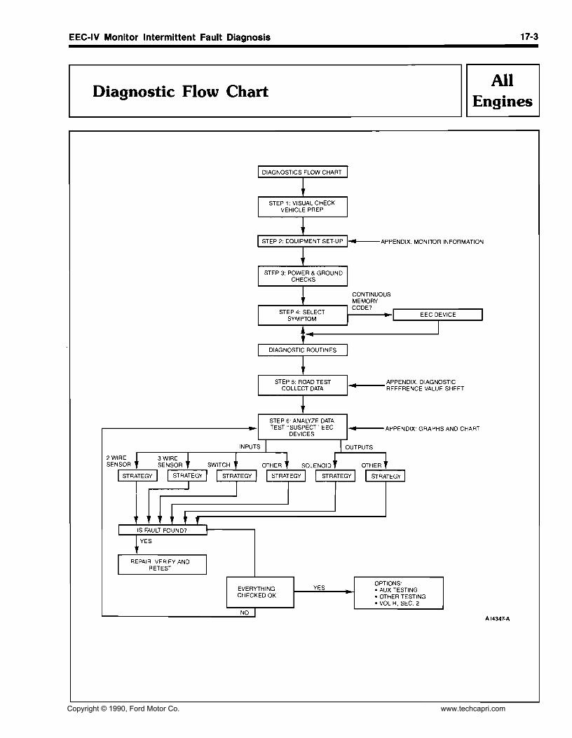
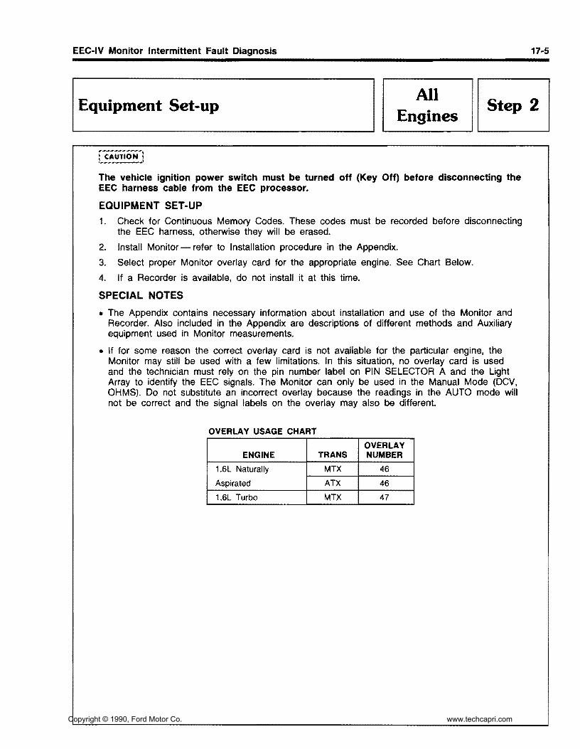
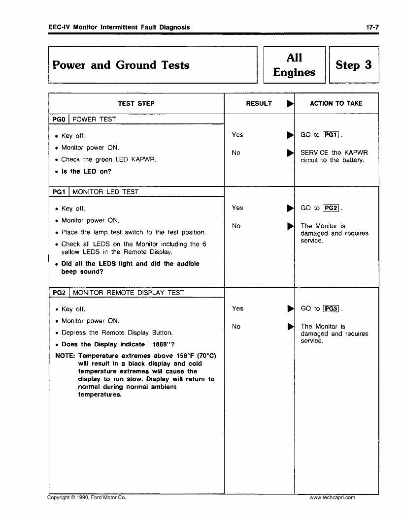
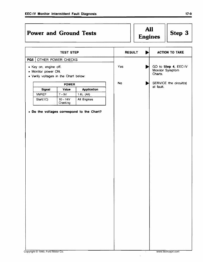
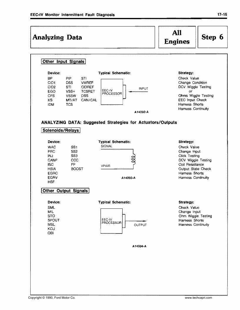
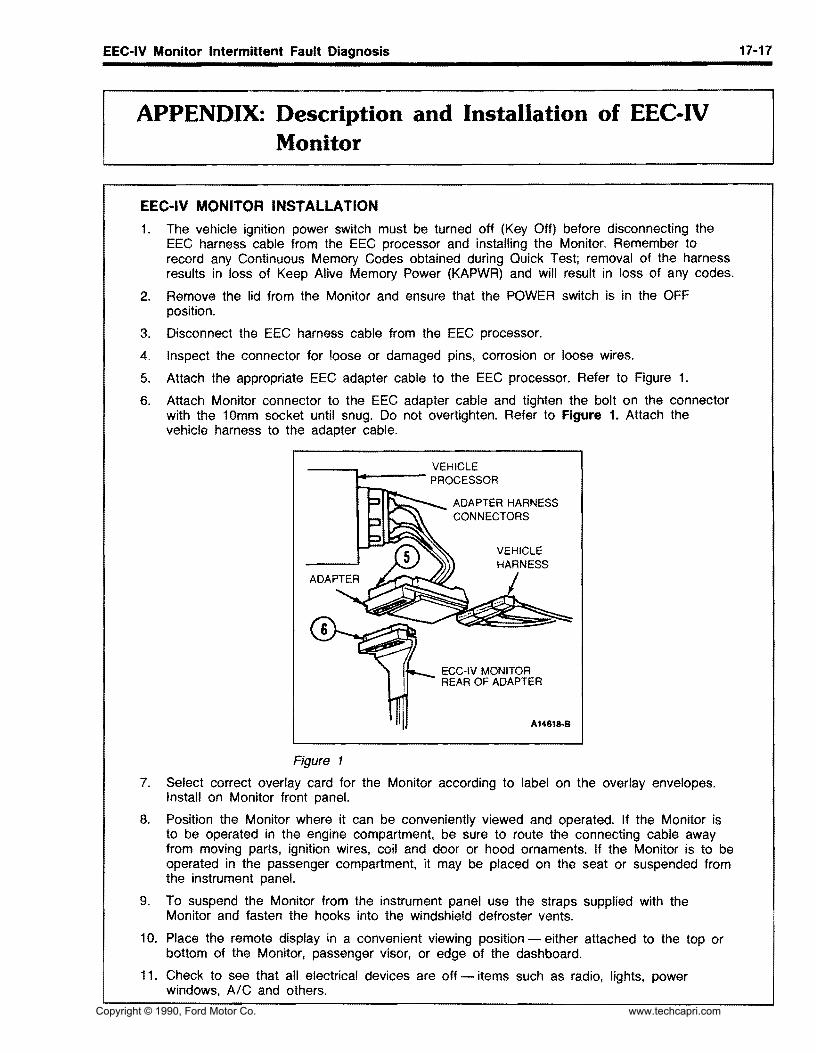
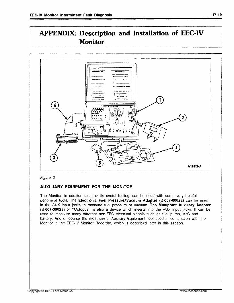
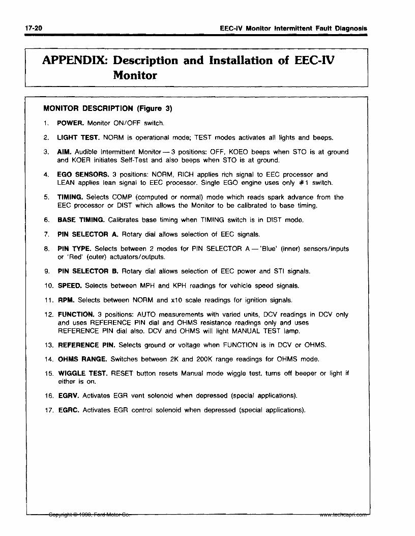
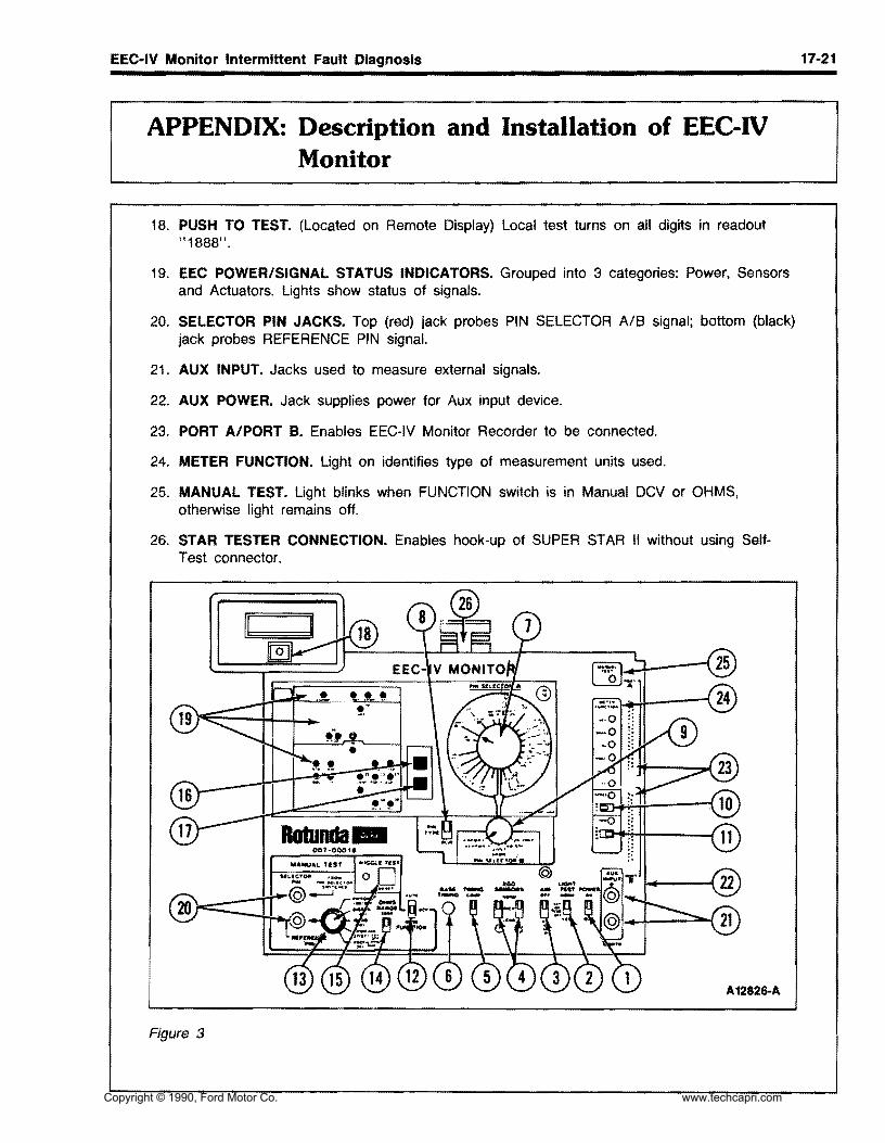
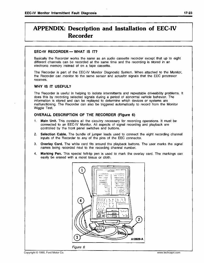
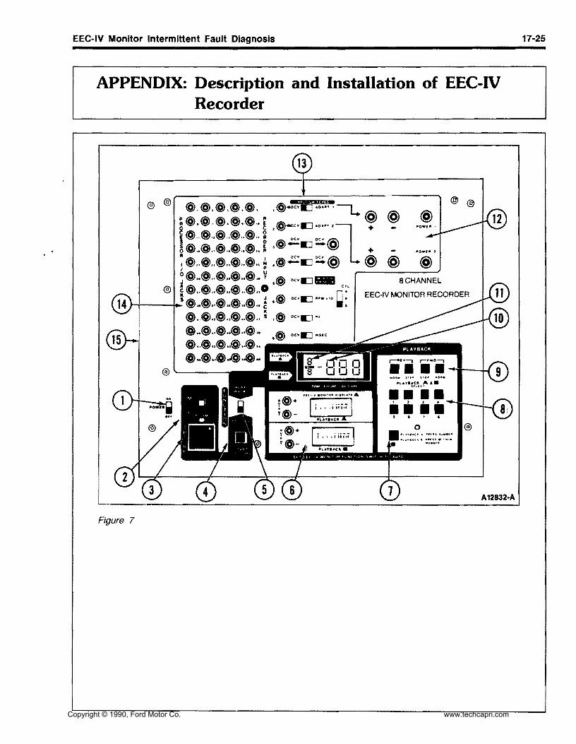
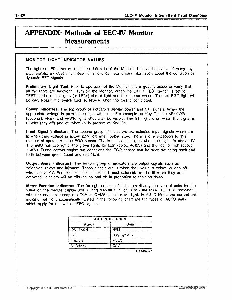

Copyright copy 1990 Ford Motor Co wwwtechcapricom
EYRieS
INTRODUCTION Most threaded fasteners are covered by specifications that define required mechanical properties such as tensile strength yield strength proof load and hardness These specifications are carefully considered in initial selection of fasteners for a given application To assure continued satisfactory vehicle performance replacement fasteners used should be of the correct strength as well as the correct nominal diameter thread pitch length and finish
Most original equipment fasteners (English system or Metric) are identified with markings or numbers indicating the strength of the fastener These markings are described in the pages that follow Attention to these markings is important in assuring that the proper replacement fasteners are used
Further some metric fasteners especially nuts are colored blue This metric blue identification is in most cases a temporary aid for production start-up and color will generally revert to normal black or bright after start-up
English system and metric system fasteners are available through your Ford Parts and Service operashytion
NOMENCLATURE FOR BOLTS
(ENGLISH) INCH SYSTEM METRIC SYSTEM Bolt12middot13xl Bolt M12middot175x25
I G- D
~~~~~~~
----L----- 1
G-Grade Marking (bolt strength)
L- Length (inches) T - Thread Pitch
(threadlinch) D-Nominal Diameter
(inches)
P- Property Class (bolt strength)
L- Length (millimeters) T shy Thread Pitch (thread width
crest to crest mm) D-Nominal Diameter
(millimeters)
The property class is an Arabic numeral distinguishable from the slash SAE English grade system The length of all bolts is measured from the underside of the head to the end
1 Copyright copy 1990 Ford Motor Co wwwtechcapricom
bull bull
EYRieS BOLT STRENGTH IDENTIFICATION (ENGLISH) INCH SYSTEM
English (Inch) bolts-Identification marks correspond to bolt strength-increasing number of slashes represent increasing strength
METRIC SYSTEM
Metric bolts-Identification class numbers correspond to bolt strength-increasing numbers represhysent increasing strength Common metric fastener bolt strength property are 98 and 109 with the class identification embossed on the bolt head
HEX NOT STRENGTH IDENTIFICATION (ENGLISH) INCH SYSTEM METRIC SYSTEM
Grade Hex Nut Hex Nut Class Hex Nut Hex Nut Grade 5 Grade 8 Property Property
Class 9 Class 10 Identification Identification
3 Dots 6 Dots Arabic 9 Arabic 10 Increasing dots represent increasing strength May also have blue finish or paint daub on hex flat
Increasing numbers represent increasing strength
OlHER TYPES Of YARTS Metric identification schemes vary by type of part most often a variation of that used of bolts and nuts Note that many types of English and metric fasteners carry no special identification if they are otherwise unique
9
-Stamped UmiddotNuts CLASS CLASS CLASS
109 98 88
-Studs Large studs may carry the property class - Tapping thread forming and certain other case number Smaller studs use a geometric code on
hardened screws the end
2 Copyright copy 1990 Ford Motor Co wwwtechcapricom
EYRieS ENGLISH METRIC CONVERSION
Description Multiply By For Metric Equivalent
ACCELERATION Footsec2 03048 ~tresec (ms~ Inchsec2 00254 etresec2
TORQUE Pound-inch 011298 wton-metres (Nm) Pound-foot 13558 wton-metres
POWER horsepow kilowatts (kw)0746 PRESSURE or STRESS inches of 02488 kilopascals (kPa)
poundssq in 6895 kilopascals (kPa)
poundssq in 145 bar BTUENERGY or WORK 1 055 joules (J)
foot-pound 13558 joules (J) kilowatt-hour 3600000 joules (J =one Ws)
or 36 x 106
I-----shyLIGHT foot candle lumensmetre2 (Imm2)1076 FUEL PERFORMANCE milesgal 0425 1 ~resllitre (kmI)
galmile 23527 ilometre (lIkm) VELOCITY mileshour 16093 kilometreshr (kmh) LENGTH inch 254 millimetres (mm)
foot 03048 metres (m) yard 09144 metres (m) mile 1609 kilometres (km)
IAREA millimetres2 (mm2)inch2 6452 centimetres2 (cm2)645 metres2(m2)F 00929
rd 2 0836 1 metres2
mmlVOLUME inchl 16387 cm Jinchl 16387
quart 00164 litres (1) quart 09464 litres gallon 37854 litres
metres 3 (ml)yard J 07646 MASS pound 04536 kilograms (kg)
ton 90718 kilograms (kg) ton 090718 tonne
FORCE kilogram 9807 newtons (N) ounce 02780 newtons pound 4448 newtons
TEMPERATURE 0556 (OF -32)degree farenheit degree Celsius (0C)
3
I
Copyright copy 1990 Ford Motor Co wwwtechcapricom
ElRles DECIMAL AND METRIC EQUIVALENTS
Fractions Decimal Inch 164 015625 132 03125 364 046875 1116 0625 564 078125 332 09375 764 109375 18 125 964 140625
Metric mm 397 794
1191 1588 1984 2381 2778 3175 3572
Fractions Decimal Inch Metric mm 3364 515625 13097
bull
1732 53125 13494 546875 138913564
14288916 5625 578125 146843764
1932 59375 15081 3964 609375 15478
1587558 625 164 640625 16272
15625532 1164 171875
1875316 1364 203125
21875732 1564 234375
250114 1764 265625 932 28125
2968751964 516 3125
3969 4366 4763 5159 5556 5953 635 6747 7144 754 7938
21132 65625 16669 4364 671875 17066 1116 6875 17463 4564 703125 17859 2332 71875 18256 4764 734375 18653
34 750 1905 4964 765625 19447 2532 78125 19844 5164 796875 20241 1316 8125 20638
21164 328125 1132 34375
3593752364 38 375
8334 8731 9128 9525
5364 2732 1564
8
21034828125 84375 21431
21828859375 875 22225
3906252564 1332 40625 2764 421875
716 4375
9922 10319 10716 11113
5764 2932 5964 1516
890625 22622
90625 23019
921875 23416
9375 23813 2964 453125 1532 46875 3164 484375
112 500
11509 11906 12303 127
6164 953125 24209 246063132 96875
6364 984375 F25003 1 254100
4 Copyright copy 1990 Ford Motor Co wwwtechcapricom
I
EYRieS TORQUE CONVERSION
POUNDmiddotFEETNEWTON METRES (Nmiddotm) (LBmiddotFn 073761 152 223 304 375 446 527 598 669 7410
15 111 14820 18425 22130 25835 29540 36950 44360 51670 59080 66490 738100 811110 885120 959130
140 1033 1106150 1180160 1254170 1328180 1401190 1475200 1660225 1844250
POUNDmiddotFEET NEWTON METRES (LBmiddotFn (Nm)
1 1356 2 27 3 40 4 54 5 68 6 81 7 95 8 108 9 122
10 136 15 203 20 271 25 339 30 407 35 475 40 542 45 610 50 678 55 746 60 814 65 881 70 949 75 1017 80 1085 90 1220
100 1356 110 1491 120 1627 130 1763 140 1898 150 2034 160 2169 170 2305 180 2440
5 Copyright copy 1990 Ford Motor Co wwwtechcapricom
Copyright copy 1990 Ford Motor Co wwwtechcapricom
ALPHABETICAL INDEX
A AIC amp Refrigerant System - Service 36-32-1 Compressor amp Magnetic Clutch 36-32-2 Condenser 36-32-2 Diagnosis amp Testing 36-32-4 Evaporator 36-32-3 Manifold Gauge Set 36-32-17 ReceiverDrier 36-32-2 Refrigerant System Service 36-32-17 Service Precautions 36-32-2 Service Tools 36-32-22 System Charging 36-32-18 System Components 36-32-20 System Discharging 36-32-17 System Evacuating 36-32-17 Thermostatic Expansion Valve TXV 36-32-3
AC-Heater System Manual 36-41-1 AC Auxiliary Fan 36-41-11 AlC Hose 36-41-10 Air Distribution 36-41-3 Airflow 36-41-2 Blower Switch 36-41-1 Condenser 36-41-9 Disassembly amp Assembly 36-41-12 Evaporator Assembly 36-41-10 Operation 36-41-8 Receiver Dryer 36-41-10 Removal amp Installation 36-41-9 Specifications 36-41-13 Temperature Control 36-41-3
Air Cleaner amp Duct Systems 24-41-1 Air Cleaner Assembly 24-41-2 Removal amp Installation 24-41-1 Testing 24-41-1
Alternator - Integral Regulator - External Fan Type 31-17-1
Adjustments 31-17-2 Cleaning amp Inspection 31-17-11 Disassembly amp Assembly 31-17-3 On-Bench Testing 31-17-12 Removal amp Installation 31-17-2 Service Tools 31-17-16 Specifications 31-17-16 Testing 31-17-12 Voltage Regulator 31-17-2
Antennas 35-10-1 Diagnosis amp Testing 35-10-1 Removal amp Installation 35-10-2
Ash Receptacles amp Cigar Lighter 35-40-1 Diagnosis amp Testing 35-40-1 Removal amp Installation 35-40-3
B Batteries 31middot02-1 Battery Capacity Test 31-02-3 Battery Charging 31-02-3 Battery Voltage Check 31-02-1 Cleaning 31-02-6 Maintenance 31-02-5 Removal amp Installation 31-02-4 Service 31-02-4 Service Tools 31-02-6 Testing 31-02-1 Tools 31-02-4
Body 47-02-1 Alignment 47-02-8 Body amp Sheet Metal 47-02-1 Body Panels 47-02-8 Bumper Assembly Front 47-02-2 Bumper Assembly Rear 47-02-3 Bumper Covers 47-02-11 Engine Compartment Underbody Panels 47-02-7 Exterior Parts Flexible - Refinishing 47-02-15 Fender 47-02-6 Inner Splash Shield Front Fender 47-02-5 Removal amp Installation 47-02-2 Repair 47-02-11 Specifications 47-02-15 Splash Shield A-Pillar 47-02-6 Stone Guard Front 47-02-8 Support amp Bracket Front Center 47-02-8
Body Shell Exterior Trim Frame amp Underbody - Service 47-01-1
Adjustments 47-01-2 Appearance Protection 47-01-9 Body Alignment Unitized 47-01-2 Body Dimensions 47-01-3 Body Maintenance 47-01-9 Body Misalignment Check 47-01-2 Body Sealer Types 47-01-2 Body Side Protection Mouldings 47-01-7 Cleaning amp Inspection 47-01-7 Diagnosis amp Testing 47-01-2 Dust amp Water Leaks 47-01-2 Floorpan Plugs amp Grommets 47-01-7 Rattle Elimination 47-01-8 Removal amp Installation 47-01-7
Copyright copy 1990 Ford Motor Co wwwtechcapricom
ALPHABETICAL INDEX
Service Tools 47-01-10 Trim 47-01-8 Underbody Misalignment Check 47-01-2
Brake Booster Vacuum - Dash Mounted 12-50-1 Adjustments 12-50-2 Inspection 12-50-3 Master Cylinder Push Rod Adjustment 12-50-2 Power Booster 12-50-3 Push Rod Length 12-50-2 Removal amp Installation 12-50-3 Service Tools 12-50-3 Vacuum Hose amp Check Valve 12-50-3
Brakes Disc - Single Piston Sliding Caliper - Front 12-20-1
Brake Pads 12-20-3 Brake Rotor Refinishing 12-20-11 Caliper 12-20-5 Disassembly amp Assembly 12-20-8 Overhaul 12-20-10 Removal amp Installation 12-20-3 Rotor 12-20-7 Service Precautions 12-20-3 Service Tools 12-20-12 Specifications 12-20-12
Brakes Disc - Single Piston Sliding Caliper - Rear 12-25-1
Brake Pads 12-25-5 Brakes Parking 12-25-3 Caliper 12-25-8 Disassembly amp Assembly 12-25-11 Removal amp Installation 12-25-5 Rotor 12-25-9
Service Tools 12-25-13 Specifications 12-25-13
Brakes Hydraulic - Service 12-01-1 Adjustments 12-01-30 Brake Booster Functional Test 12-01-11 Brake Pedal 12-01-19 Brake Pedal Height 12-01-14 Brake Pedal Travel Measurement 12-01-14 Brake Shudder 12-01-15 Brake System - Dual 12-01-2 Brake Tube Replacement 12-01-31 Caliper Hose 12-01-21 Diagnosis amp Testing 12-01-6 Disassembly amp Assembly 12-01-22 Disc Brakes Front 12-01-4 Disc Brakes Rear 12-01-4 Hydraulic System 12-01-6 Hydraulic System Bleeding 12-01-30
Inspection 12-01-4 Master Cylinder 12-01-18 Parking Brake 12-01-5 Removal amp Installation 12-01-18 Road Test 12-01-3 Service Tools 12-01-32 Specification 12-01-32 System Priming 12-01-31
c Carpets 45-26-1 Removal amp Installation 45-26-1
Charge Indicator 33-32-1 Diagnosis amp Testing 33-32-1 Removal amp Installation 33-32-3 Voltmeter 33-32-3
Charging System - Service 31-01-1 Diagnosis 31-01-1 Specifications 31-01-8 Testing 31-01-3
Clock 33-15-1 Removal amp Installation 33-15-1
Clutch 16-02-1 Adjustments 16-02-3 Clutch Cable 16-02-5 Clutch Cover 16-02-11 Clutch Disc 16-02-11 Clutch Pedal 16-02-6 Clutch Pedal Height 16-02-3 Clutch Pedal Switch 16-02-5 Clutch Pressure Plate Disc amp Flywheel 16-02-9 Clutch Release Bearing 16-02-11 Flywheel 16-02-12 Hydraulic Clutch Bleeding 16-02-5 Hydraulic Clutch Master Cylinder 16-02-9 Hydraulic Clutch Reservoir Fluid Level 16-02-5 Hydraulic Clutch Slave Cylinder 16-02-9 Pedal Free Play 16-02-4 Removal amp Installation 16-02-5 Service Tools 16-02-15 Specifications 16-02-15
Clutch and Manual Transaxle - Diagnosis 16-01-1 Clutch amp Clutch Pedal 16-01-2 Diagnosis 16-01-2 Gear Noise 16-01-6 Oil Leakage 16-01-6 Transaxle 16-01-4
Copyright copy 1990 Ford Motor Co wwwtechcapricom
ALPHABETICAL INDEX
Compressor amp Clutch 36-39-1 Clutch Pulley Bearing 36-39-7 DCompressor 36-39-2 Maintenance 36-39-1 Pressure Plate Pulley amp Field Coil 36-39-2 Door - Hinge Latch Manual Lock and
Refrigerant Oil Addition 36-39-1 Weatherstrip 44-06-1
Removal amp Installation 36-39-2 Adjustments 44middot06-2
Service Tools 36-39-8 Door Alignment 44middot06-2 Door Bumper 44-06-7
Console Floor 45middot31middot1 Door Bumper Guide 44-06middot8
Console Front 45middot31-2 Door Check Assembly 44middot06middot7
Console Rear 45-31-1 Door Inspection 44-06-2
Removal amp Installation 45-31-1 Door Latch 44middot06middot5
Shifter Boot 45-31-4 Door Latch Release Lever 44-06-5 Door Lock Cylinder 44-06middot6
Convertible 47-07-1 Door Striker 44-06-3
Adjustments 47-07-2 Front Door amp Hinges 44middot06-4
Convertible Top Assembly 47-07-3 Outside Door Handle 44-06middot6
Convertible Top Material 47-07-4 Removal amp Installation 44-06-4
Convertible Top Retainer 47-07-4 Specifications 44-06-9
Convertible Top-to-Windshield Adjustment 47-07-3 Weatherstrip 44-06middot8
Door Glass Fit 47-07-3 Door Lock Power 44-16-1 Latch Effort 47middot07-2 Diagnosis amp Testing 44-16-2 Maintenance 47-07-1 Door Lock Actuator 44-16-5 Moulding Storage Cover-to-Convertible Top 47-07-10 Door Lock Control Switch 44-16-6 Plastic Window Rear 47-07-2 Removal amp Installation 44-16-5 Removal amp Installation 47-07middot3 Specifications 44middot16middot6 Specifications 47-07-17 Storage Compartment Lock Set amp Actuator 47middot07-13 Drive Belts Accessory - Service 27-02middot1
Storage Cover 47-07-15 Adjustments 27middot02-1
Storage Cover Bumpers 47middot07middot15 AlternatorWater Pump Drive Belt Tension 27middot02-1
Storage Cover Hinge 47-07-17 Drive Belt Alternator 27middot02-3
Storage Cover Latch Cables 47-07-13 Drive Belt Power Steering amp AlC 27middot02-4
Storage Cover Pivot Caps 47middot07middot12 Power Steering amp AC Drive Belt Tension 27-02middot2
Storage Cover Strikers 47-07-14 Removal amp Installation 27-02middot3
Storage Cover Support 47middot07-16 Storage Cover Trim 47-07-15 Storage Top Latch 47middot07-13 E Weatherstrip Covertible Top-to-Windshield 47-07middot10 Weatherstrip Rear Seat-tomiddotStorage Cover 47-07-11 Engine Coolant Temperature Indicating System 33-25-1 Weatherstrip Storage Covermiddotto-Body 47-07-11 Diagnosis amp Testing 33-25-1 Weatherstrips Convertible Top Side 47-07-10 Removal amp Installation 33middot25-5 Window Rear 47-07-4 Temperature Sending Unit 33-25-5
Cooling System - Service 27-01-1 Engine 16L 21middot10-1 Coolant Condition Check 27-01-6 Camshaft 21middot10-14 Coolant Draining amp Replacement 27-01-7 Camshaft Seals 21-10-22
Cooling System Flush Procedure 27-01-7 Connecting Rod 21-10-39 Cooling System Pressure Test 27-01-5 Core Plugs 21-10-23 Diagnosis amp Testing 27-01middot2 Crankshaft 21-10-39 Pressure Cap Testing 27-01middot4 Crankshaft End Play 21-10middot40 Service Tools 27-01-8 Crankshaft Main Bearings amp Connecting Thermostat Testing 27-01middot6 Rod Bearings 21-10-16
Copyright copy 1990 Ford Motor Co wwwtechcapricom
ALPHABETICAL INDEX
Crankshaft Oil Clearance 21-10-40 Diagnosis amp Testing 27middot10middot2 Crankshaft Oil Seal Front 21-10-23 Removal amp Installation 27-10-9 Crankshaft Oil Seal Rear 21middot10-23 Specifications 27-10-10 Cylinder Block 21-10-34
Fuel Filters 24-51-1 Cylinder Block Flatness 21-10middot35
Inmiddot Line Filter 24-51-1 Cylinder Bores 21-10-36
In-Tank Filter 24-51middot1 Cylinder Head 21-10-42
RemOVAl amp Installation 24-51-1 Disassembly amp Assembly 21-10-24 Engine Mount Front 21middot10middot9 Fuel Injection Electronic 24-05-1 Engine Mount Rear 21middot10middot9 Adjustments 24-05-13 Engine Mounts RH 21-10-9 Airflow 24-05-8 Exhaust Manifold 21middot10-18 Air Induction System 24-05-6 HLA 21-10-46 BAC Valve 24-05-16 Intake Manifold 21-10-17 BP Sensor 24-05-16 Oil Pan 21-10middot19 Bypass Air Control Valve 24-05-9 Oil Pump 21-10-20 Diagnosis amp Testing 24-05-13 Piston amp Connecting Rod Assembly 21-10-21 Electronic Control Assembly 24-05-14 Pistons Piston Rings amp Piston Pins 21-10-37 Electronic Engine Control 24-05middot10 Removal amp Installation 21-10-2 Engine Coolant Temperature Sensor 24-05-15 Service Procedures 21-10-34 Fuel Injectors 24-05-15 Service Tools 21-10-49 Fuel System 24-05-4 Specifications 21-10-47 Idle Speed 24-05-13 Subassemblies 21middot10-32 Oxygen Sensor 24-05-16 Timing Belt 21-10-12 Removal amp Installation 24-05-13 Valve Stem Seals 21-10-19 Service Tools 24-05-17
Specifications 24-05-17Engine Gasoline - Service 21-01-1
Throttle Body 24-05-13 Camshaft Lobe Lift 21-01-4
Throttle Position Sensor 24-05-15 Compression Test 21-01-3
Turbo Boost Gauge 24middot05-16 Diagnosis amp Testing 21-01-2
Vane Air Flow Meter 24-05-14 Emissions Calibration Label 21-01-2 Engine Identification 21-01-2 Fuel Level Indicating System 33-20-1 Engine Oil Leaks 21middot01-2 Diagnosis amp Testing 33-20middot1 Exhaust Emission Control System 2101-2 Fuel Gauge 33-20-3 Positive Closed-Type Crankcase Ventilation Fuel Tank Sending Unit 33-20middot3
System 21-01-2 Removal amp Installation 33-20-3 Service Tools 21middot01-5
Fuel Pump - Electric 24-35-1 Valve Train Analysis 21-01-4
Control Circuit 24-35-2 Exhaust System 26-01-1 Fuel Pump Relay 24-35-4 Diagnosis 26-01-1 Pressure Regulator 24-35-3 Exhaust Leakage or Noise 26-01-1 Removal amp Installation 24-35-3 Removal amp Installation 26-01-4 Fuel System - Service 24-01-1 Restricted Exhaust System 26-01-3
F
Air Cleaner 24-01-2 Cleaning amp Inspection 24-01-2 Fuel Injection Electronic 24-01-2 Testing amp Adjustments 24-01-2
Fuel Tanks and Lines 24-50-1
Fan Electro-Drive Cooling 27-10-1 Fuel Filler Door 24-50-3
Coolant Temperature Switch 27-10middot9 Fuel Filler Neck 24-50-5
Cooling Fan 27-10middot9 Fuel System Pressure Relief 24-50-2
Cooling Fan Motor 27-10-9 Fuel Tank 24-50-4
Cooling Fan Relay 27-10-10 Removal amp Installation 24-50-2
Copyright copy 1990 Ford Motor Co wwwtechcapricom
ALPHABETICAL INDEX
Fuses amp Circuit Breakers 34-50-1 Fuse link 34-50-4 Fuse link Charging System 34-50-3
Fuse Panel Interior 34-50-3 Main Fuse Box 34-50-3 Removal amp Installation 34-50-3
G Glass Stationary - Windshield 43-02-1 Mouldings Front Window 43-02-1 Removal amp Installation 42-02-1 Windshield 43-02-4
H Halfshafts amp CV Joints - Front-Wheel Drive 15-22-1 Diagnosis 15-22-5 Disassembly amp Assembly 15-22-11 Halfshaft Handling 15-22-4 J oint shaft 15-22-11 Removal amp Installation 15-22-8 Rzeppa CV Joint 15-22-13 Service Tools 15-22-22 Specifications 15-22-22 Tripo Joint 15-22-19
Hardtop Removable 47-10-1 Exterior Mouldings Side amp Rear 47-10-4 Hardtop Front Attachment Bracket 47-10-5 Hardtop Side amp Rear Windows 47-10-6 Hardtop-to-Vehicle Weatherstrip 47-10-4 Headlining 47-10-6 Mouldings Roof 47-10-4 Removal amp Installations 47-10-1 SideRear Attachments 47-10-5 Side Window Opening Weatherstrip 47-10-4 Trim Panel Rear 47-10-3 Trim Panels Interior Side 47-10-3 Window Retainer Moulding Side 47-10-3 Wiring Harness 47-10-5
Headlamp System 32-02-1 Adjustments 32-02-15 Diagnosis amp Testing 32-02-6 Fog Lamp 32-02-18 Fog Lamp Switch 32-02middot18 Headlamp Aim 32middot02middot15 Headlamp Assembly 32middot02middot16 Headlamp Motor 32middot02middot16 Headlamp Motor Switch 32middot02middot18 Headlamp Switch 32middot02middot17 High BeamFlashmiddottomiddotPass Switch 32middot02middot18
High Beam Indicator Lamp Bulb 32-02middot18 Linkage 32middot02-17 Removal amp Installation 32-02middot15
Heater amp Power Ventilation System 36-10middot1 Adjustments 36-10-15 Air Distribution 36middot10-2 Air Door Control Cable 36-10-16 Airflow 36-10middot1 Air Inlet Duct 36middot10middot26 Blower Case Assembly 36-10-19 Blower Motor 36-10-18 Blower Motor Resistor 36-10-18 Blower Switch 36-10middot17 Control Cables 36middot10-17 Defroster Ducts 36-10middot24 Defroster Tubes amp Side Demister Tubes 36middot10middot25 Diagnosis amp Testing 36middot10middot5 Function Selector Cable 36middot10middot15 Function Selector Rod 36-10-15 Heat Ducts Rear Seat 36middot10-25 Heater Case 36middot10-20 Heater Control Panel 36-10-16 Heater Core 36-10-22 Heater Hoses 36-10-23 Heater Tube LH 36middot10-27 Instrument Panel Ducts 36middot10-26 Register LH Side amp Center 36middot10middot24 Register RH Side 36-10-24 Removal amp Installation 36-10-16 Temperature Control 36-10middot2 Temperature Control Cable 36-10-15
Heating System - Service 36-01-1 Bench Test 36-01-3 Diagnosis 36-01-4 Heater Core 36-01middot2 Heater Core Leak Test 36middot01middot3 Heating Systems amp Control Doors 36middot01middot2 Pressure Test 36middot01-3 Service Tools 36middot01middot5 Testing 36-01-2
HOisting Jacking amp Towing 10middot04middot1 Hoisting amp Jacking 10middot04middot1 TmiddotHooks Front 10middot04-5 TmiddotHooks Rear 10middot04middot5 Towing 10-04-3 Towing Procedures 10-04-4 Towing Slings 10middot04middot3
Hood Hinge amp latch 44-08-1 Adjustments 44-08-2 Hood 44-08middot8 Hood Alignment 44-08-2 Hood Bumpers 44-08middot3 Hood Hinge 44middot08-5 Hood Latch 44middot08middot5 Copyright copy 1990 Ford Motor Co wwwtechcapricom
ALPHABETICAL INDEX
Hood Release Cable 44-08-6 Instrument Panel amp Glove Compartment 45-61-1 Hood Safety Latch 44-08-6 Instrument Cluster Bezel 45-61-1 Hood Seals 44-08-5 Instrument Panel Assembly 45-61-2 Hood Support Rod 44-08-7 Removal amp Installation 45-61-1 Hood Weatherstrip 44-08-4 Latch Adjustments 44-08-2
Removal amp Installation 44-08-3
Horns 35-80-1 Adjustments 35-80-3 Lamps Interior 32-60-1 Diagnosis amp Testing 35-80-1 Diagnosis amp Testing 32-60-2 Horn Relay 35-80-4 Door Switch 32-60-7 Horn Switch 35-80-4 LampBlub Glove Compartment 32-60-8 Removal amp Installation 35-80-3 Lamp Dome 32-60-6
Lamps Courtesy 32-60-7
LensBulb Cargo Lamp 32-60-9 Removal amp Installation 32-60-6
Lamps - Parking Rear and Marker 32-20-1 Identification Codes 10-01-1 Combination LampBulb Replacement 32-20-7 Anti-Theft Labels 10-01-2 Combination Lamp Rear 32-20-6 Exteriorllnterior Labels 10-01-4 Diagnosis amp Testing 32-20-2 Label Locations 10-01-3 Hi-Mount Brakelamp 32-20-7 Official Vehicle Identification Number 10-01-1 License Plate LampBulb 32-20-7 Replacement VIN Label 10-01-2 Parking LampBulb Front 32-20-6 Vehicle Certification Label 10-01-2 Removal amp Installation 32-20-6
Side Marker LampBulb Front 32-20-6Ignition Switch 31-20-1
Side Marker Lamps Rear 32-20-8Ignition Lock Tumbler 31-20-2
Stop lamp Switch 32-20-8Non-Functioning Locks 31-20-3 Removal amp Installation 31-20-2 Lubrication Points and Lubricant Switch Blade-Type 31-20-1 Specifications 10-03-1 Testing 31-20-1 Lubrication 10-03-1
Specifications 10-03-3Ignition System Service 23-03-1 Diagnosis amp Testing 23-03-2 Luggage Compartment - Door Hinge Latch Disassembly amp Assembly 23-03-4 Lock and Weatherstrip 44-10-1 Distributor 23-03-4 Adjustments 44-10-1 Distributor Cap amp Rotor 23-03-2 Alignment 44-10-1 Ignition Coil 23-03-3 Door 44-10-3
Operation 23-03-2 Door Bumpers 44-10-8 Gas Lift Cylinders 44-10-6Removal amp Installation 23-03-2
Secondary Ignition Wires 23-03-2 Glove Compartment 44-10-9
Spark Plugs 23-03-3 Hinge 44-10-5 Latch 44-10-5
Instrument Cluster 33-01-1 Latch Glove Compartment 44-10-10 Diagnosis amp Testing 33-01-4 Lock Cylinder 44-10-5 Disassembly amp Assembly 33-01-12 Lock Glove Compartment 44-10-10 Heater Control Panel Bulb 33-01-11 Removal amp Installation 44-10-2 Instrument Cluster Bulbs 33-01-11 Spoiler 44-10middot8 Panel Dimmer SWitch 33-01-11 Striker 44-10-2 Removal amp Installation 33-01-10 Striker Glove Compartment 44-10-9 Speed Sensor 33-01-11 Weatherstrip 44-10-7
Copyright copy 1990 Ford Motor Co wwwtechcapricom
ALPHABETICAL INDEX
M Mirrors Exterior 42-25-1 Diagnosis amp Testing 42-25-2 Mirror Assembly 42-25-7 Removal amp Installation 42-25-7 Switch 42-25-7
Mirrors Inside 42-21-1 Removal amp Installation 42-21-1
Mouldings 45-16-1 Convertible Top Retainer 45-16-1 Door Scuff Plate amp Side Trim 45-16-4 Hardtop Header Trim Cover 45-16-3 Removal amp Installation 45-16-1 Specifications 45-16-4 Windshield Moulding Side 45-16-2 Windshield Moulding Upper 45-16-2
N Noise Vibration and Harshness 18-01-1 Diagnosis ampTesting 18-01-6 Diagnostic Theory 18-01-1 Glossary 18-01-2 Non-Transaxle Noise 18-01-4 NVH Diagnosis 18-01-4 Road Test 18-01-4 Service Tools 18-01-12 Transaxle Noise 18-01-4
o Oil Pressure Indicating Svstem 33-34-1 Diagnosis amp Testing 33-34-1 Oil Pressure Sending Unit 33-34-4 Removal amplnstallaon 33-34-4
p I Parking Brake Cable Actuated shy
Rear Wheels 12-70-1 Adjustment 12-70-2 Cable Parking Brake 12-70-2
Cables Long 12-70-4 Parking Brake Lever 12-70-3 Removal amp Installation 12-70-3
R Radiator 27-03-1 Cleaning External amp Internal 27-03-13 Leak Testing 27-03-13 Oil Cooler Transfer or Replacement 27-03-13 Radiator Core 27-03-14 Radiator Tank 27-03-5 Removal amp Installation 27-03-3 Service Procedures 27-03-14 Service Tools 27-03-17 Testing 27-03-13 Thermostat 27-03-5 Water Pump 27-03-4
Restraint Svstem - Supplemental Air Bag 41-58-1 Air Bag Clockspring 41-58-32 Air Bag Module 41-58-31 Backup Power Supply 41-58-32 Deactivating the System 41-58-29 Deployed Air Bag 41-58-28 Descriptions 41-58-1 Diagnosis ampTesting 41-58-4 Diagnostic Assembly 41-58-31 Disposal Procedures 41-58-27 Live Air Bags 41-58-27 Operation 41-58-4 Parts Replacement 41-58-26 Reactivating the System 41-58-29 Removal amp Installation 41-58-29 Sensor Front Center 41-58-29 Sensor Front Left or Right 41-58-30 Sensor Rear 41-58-30 Service Precautions 41-58-27 Specifications 41-58-32 Undeployed Air Bag Faulty 41-58-28
I s Scheduled Maintenance 10-02-1 Emission Control Information Decal 10-02-1 Maintenance Schedules 10-02-3
Seat and Shoulder Safetv Belts 41-50-1 Belt Webbing 41-50-5
Copyright copy 1990 Ford Motor Co wwwtechcapricom
ALPHABETICAL INDEX
Buckle Assembly Front 41-50-2 Cleaning 41-50-5 Major Service Operations 41-50-4 Removal amp Installation 41-50-2 Retractor amp Harness Assembly Front 41-50-2 Retractor amp Harness Assembly Rear 41-50-3 Safety Belt Maintenance 41-50-4 Seat Buckle Rear 41-50-4
Seat Child Restraint - Tether Attachment 41-52-1 Installation 41-52-1
Seats Front 41-04-1 Head Restraint amp Cover 41-04-7 Lumbar Support 41-04-8 Reclining Mechanisms 41-04-7 Removal amp Installation 41-04-1 Seat Back 41-04-4 Seat Back Cover amp Cushion 41-04-5 Seat Cover amp Cushion 41-04-3 Seat Height Adjuster LH Seat 41-04-9 Seat Height Adjustment Mechanism Control
Assembly LH Seat 41-04-9 Specifications 41-04-10
Seats Rear 41-20-1 Actuator Lock Set 41-20-8 Cable Actuator 41-20-7 Latch Seat Back 41-20-5 Latch Cable Seat Back 41-20-6 Removal amp Installation 41-20-1 Seat Back amp Cover 41-20-1 Seat Cushion 41-20-4
Shift Control Linkage 17-02-1 Adjustments 17-02-2 Disassembly amp Assembly 17-02-7 Gear Selector 17-02-7 Gear Selector Assembly 17-02-5 Removal amp Installation 17-02-4 Shift Control Cable 17-02-4 Specifications 17-02-10
Sound Systems 35-01-1 AMFM Multiplex Radio - ESR 35-01-3 AMFM Multiplex with Cassette Player 35-01-4 Cassette Tape Player 35-01-3 Diagnosis amp Testing 35-01-6 Premium Sound 35-01-2 Premium Sound Amplifier 35-01-18 Radio Reception 35-01-2 Removal amp Installation 35-01-17
Speakers 35-30-1 Diagnosis 35-30-1 Door Mounted Speakers 35-30-2
Rear Seat Speakers 35-30-3 Removal amp Installation 35-30-2
Speed Control System 37-01-1 Actuator 37-01-11 Actuator Cable 37-01-9 Adjustments 37-01-9 CableActuator Assembly 37-01-10 Clutch Pedal Height 37-01-9 Control Module 37-01-10 Control Switches 37-01-9 Diagnosis amp Testing 37-01-3 Removal amp Installation 37-01-9
Speedometer 33-10-1 Assembly 33-10-4 Diagnosis amp Testing 33-10-1 Removal amp Installation 33-10-3 Speedometer Cable Core 33-10-4 Speedometer Driven Gear 33-10-4
Starter Positive Engagement 28-02-1 Disassembly amp Assembly 28-02-5 Jump Starting 28-02-2 Pinion Depth Adjustment 28-02-3 Removal amp Installation 28-02-5 Service Tools 28-02-13 Specifications 28-02-13 Starter Motor No-Load Test 28-02-4 Testing 28-02-2
Starting System - Service 28-01-1 Diagnosis amp Testing 28-01-2 Neutral Safety Switch 28-01-7 On-Vehicle Inspection 28-01-2 Removal amp Installation 28-01-7 Service Tools 28-01-7 Voltage Drop Tests 28-01-3
Steering Column 13-04-1 Air Bag Module 13-04-2 Component Fasteners 13-04-2 Disassembly amp Assembly 13-04-6 Intermediate Shaft 13-04-4 Removal amp Installation 13-04-3 Specifications 13-04-10 Steering Column Support Brackets 13-04-5 Steering Wheel 13-04-3 Turn Signal Cancel Cam Service 13-04-9
Steering Gear Power Rack-and-Pinion 13-46-1 Adjustments 13-46-5 Disassembly amp Assembly 13-46-7 Dust Boot 13-46-6 Rack Yoke Preload 13-46-5 Removal amp Installation 13-46-6
Copyright copy 1990 Ford Motor Co wwwtechcapricom
ALPHABETICAL INDEX
Service Tools 13-46-17 Specifications 13-46-17 Tie Rod End 13-46-6
Steering Power - Hoses 13-55-1 High Pressure Hose 13-55-2 PressureReturn Tubing 13-55-3 Removal amp Installation 13-55-2 Return Hose 13-55-3
Steering Pump Power 13-51-1 Adjustments 13-51-2 Cleaning amp Inspection 13-51-6 Disassembly amp Assembly 13-51-4 Drive Belt Tension 13-51-2 Fluid Level Check 13-51-2 Flushing Power Steering System 13-51-6 Power Steering Pump 13-51-4 Pressure Regulator Valve 13-51-3 Pressure Switch 13-51-3 Pump Assembly 13-51-3 Removal amp Installation 13-51-3 Start-Up Procedure 13-51-2 Testing 13-51-2
Steering - Service 13-01-1 Pump Flow amp Pressure Tests 13-01-4 Service Tools 13-01-7 Specifications 13-01-7 Steering Wheel Free Play 13-01-5 Testing 13-01-2
Suspension Front 14-10-1 Ball Joint 14-10-2 Control Arm 14-10-5 Disassembly amp Assembly 14-10-5 Removal amp Installation 14-10-2 Se+vice Tools 14-10-6 Specifications 14-10-6 Strut amp Spring 14-10-3
Suspension Rear 14-32-1 Control Arms amp Trailing Arm 14-32-7 Removal amp Installation 14-32-4 Service Tools 14-32-11 Specifications 14-32-11 Spindle 14-32-6 Strut amp Spring Rear 14-32-4
Suspension - Service 14-01-1 Adjustments 14-01-6 Ball Joints 14-01-4 Camber 14-01-6 Control Arms amp Stabilizers 14-01-4 Diagnosis amp Testing 14-01-1
Heights 14-01-3 Specifications 14-01-9 Steering Wheel Centering 14-01-8 Steering Wheel Play 14-01-4 Struts 14-01-3 Tie Rods 14-01-4 Toe Rear 14-01-7 Toe In Front 14-01-6 Wheel Alignment 14-01-4
T Tachometer 33-11-1 Diagnosis amp Testing 33-11-1 Removal amp Installation 33-11-5
Throttle Linkage 24-60-1 Adjustments 24-60-1 Free Play 24-60-1 Removal amp Installation 24-60-2 Throttle Cable 24-60-2 Wide-Open Throttle Position 24-60-1
Transaxle Automatic - 4EAT 17-27-1 2-3 Accumulator 17-27-80 3-4 Accumulator 17-27-77 Adjustments 17-27-29 Bearing Housing 17-27-94 Bearing Locator 17middot27middot96 Bearing Preload amp Shim Selection 17middot27middot31 BearingStator Support 17-27-95 Cleaning amp Inspection 17-27-97 Clutch Assemblies 17middot27middot68 Diagnosis amp Testing 17-27middot4 Differential 17middot27middot90 Disassembly amp Assembly 17-27middot42 Idler Gear 17middot27-92 Kickdown Cable 17middot27middot29 Major Service Operations 17-27-29 Oil Cooler 17middot27-31 Oil Pump 17-27-63 One-Way Clutch amp Plantary Carrier Assembly 17-27-76 Output Gear 17-27middot91 Removal amp Installation 17-27-36 Service Tools 17middot27-102 Small Sun Gear amp One-Way Clutch 17-27-74 Specifications 17-27-100 Subassemblies 17-27-63 Torque Converter 17-27-98 Transaxle Fluid Level Check 17-27-29 Valve Body 17-27-80
Copyright copy 1990 Ford Motor Co wwwtechcapricom
ALPHABETICAL INDEX
Transaxle Automatic - Service 17-01-1 Description 17-01-1
Transaxle Manual- 5-Speed - Non-Turbo Engine 16-37-1
Cleaning amp Inspection 16-37-43 Clutch Housing 16-37-25 Differential 16-37-37 Disassembly amp Assembly 16-37-17 Gearshift Linkage 16-37-13 General Service Procedures 16-37-15
Input Shaft 16-37-43 Main Shaft 16-37-44 Main Shift Rail 16-37-40
Operation 16-37-2 Removal amp Installation 16-37-5 Service Tools 16-37-46 Shift Linkage 16-37-5 Specifications 16-37-46 Subassemblies 16-37-24 Transaxle Fluid Level Check 16-37-15 Transaxle Housing 16-37-30 Transaxle Oil Seal 16-37-10
Transaxle Manual - 5-Speed - Turbo Engine 16-38middot1 Differential 16-38-39 Differential Shim Selection 16-38-63 Disassembly amp Assembly 16middot38-18 Gear amp Shaft 16-38-35 Gearshift Linkage 16-38-7 Input Gear Shaft Shim Selection 16-38-61 Input Shaft Bearing 16-38-57 Main Shaft Shim Selection 16-38-58 Operation 16-38-3 Removal amp Installation 16-38-7 Service Procedures 16-38-17 Service Tools 16-38middot66 Shift Linkage 16middot38middot6 Specifications 16middot38-65 Subassemblies 16middot38middot35 Transaxle Fluid Level Check 16middot38middot17 Transaxle Oil Seal 16-38middot9
Trim Panels Interior 45middot03middot1 Convertible Top Storage Compartment 45middot03middot13 Cowl Side Trim Panel 45-03-8
Door Trim Panels 45middot03middot1
Floor Panels Luggage Compartment 45middot03-15 Luggage Compartment Rear Trim Panels 45-03-14 Luggage Compartment Side Trim Panels 45middot03-14
Rear Quarter Trim Panels 45middot03-8
Removal amp Installation 45middot03-1 Watershield 45-03-7
Turbo Boost Indicating System 33middot36middot01 Boost Gauge 33middot36middot3 Boost Gauge Sensor 33-36middot3 Diagnosis amp Testing 33-36middot1
Removal amp Installation 33middot36middot3
Turbocharger 24middot45middot1 Air-FuelExhaust Gas Flow 24-45-2 Bearing Clearance Check 24-45-9 Boost Control Automatic 24middot45-2 Coolant Return Hose 24middot45-7
Coolant Supply Hose amp Fitting 24-45-7 Diagnosis amp Testing 24middot45middot9 Intercooler 24middot45middot7 Intercooler Hoses 24middot45middot8 Lubrication 24middot45middot1 Oil Return Hose 24middot45middot7 Oil Supply Line 24middot45middot6 Operation 24middot45-2 Overboost Pressure Switch 24middot45-8 Removal amp Installation 24-45-2 Specifications 24-45-12
Turn Signal and Hazard Flasher 32middot40-1 Diagnosis amp Testing 32middot40middot2
Hazard Flasher Unit 32middot40-7 Removal amp Installation 32middot40middot6
SWitch Assembly 32middot40middot6 Turn Signal Flasher Unit 32middot40middot7
Wiper Switch amp Turn Signal High Beam Lever 32middot40middot6
w Warning Indicator 33-45middot1 Brake Indicator 33middot45-1 Diagnosis amp Testing 33middot45middot3 Engine Warning Lamp 33-45middot1 High Beam Indicator 33middot45middot2 Instrument Panel Lamps 33middot45middot1 Parking Brake Switch 33middot45middot10 Removal amp Installation 33middot45middot10
Safety Belt Indicator 33middot45middot1 Safety Belt Switch 33middot45middot11 Warningllndicator Lamp Bulbs 33middot45middot10
Wheel Hubs and Bearings - Front 11middot10-1 Bearing Front 11-10middot2 Brake RotorlWheel Hub 11-10-9
Diagnosis 11-10-2
Disassembly amp Assembly 11-10middot9 Removal amp Installation 11middot10middot3
Copyright copy 1990 Ford Motor Co wwwtechcapricom
ALPHABETICAL INDEX
Service Tools 11-10-15 Removal amp Installation 42-08-6
Specifications 11-10-15 Window Channel Rear 42-08-11
Steering KnuckleBearings 11-10-13 Window Channels 42-08-6
Wheel HubSteering Knuckle Assembly 11-10-3 Window Glass 42-08-7
Window Guide 42-08-7 Wheel Hubs amp Bearings - Rear 11-15-1
Window Stop 42-08-6 Adjustments 11-15-6
Bearing Preload 11-15-6 Windshield Washers 35-70-1
Bearing Races 11-15-9 Diagnosis amp Testing 35-70-2
Brake RotorBearing Hub Assembly 11-15-7 Nozzles amp Hose 35-70-4
Grease SealBearings 11-15-8 Pump 35-70-4
Inspection 11-15-2 Removal amp Installation 35-70-4
Removal amp Installation 11-15-7 Reservoir amp Washer Pump 35-70-4
Specifications 11-15-9 Washer Switch 35-70-5
Wheels and Tires - Service 11-01-1 Windshield Wipers 35-60-1
Diagnosis 11-01-5 Adjustments 35-60-8
Maintenance 11-01-2 Diagnosis amp Testing 35-60-3
Road Test 11-01-6 Linkage 35-60-10
Service 11-01-10 Removal amp Installation 35-60-8
Service Tools 11-01-14 Specifications 35-60-10
Specifications 11-01-13 Windshield Wiper Arm Position 35-60-8
Tire and Wheel Balance 11-01-11 Wiper Arm 35-60-9
Tire Inflation 11-01-3 Wiper Blade 35-60-8
Tire Lead 11-01-9 Wiper Motor 35-60-9
Vibration amp Roughness 11-01-6 Wiper Switch amp Lever 35-60-10
Wheel Lug Nuts 11-01-2 Wiring Harness - Connectors 34-01-1
WheelTire Runout 11-01-9 Connectors 34-01-1
Window Glass amp Mechanisms - Service 42-01-1 Removal amp Installation 34-01-1
Lubrication 42-01-1 Wire Ends 34-01-2
Wiring Harnesses 34-26-1Window Rear - Defroster 36-86-1 Dash Panel 34-26-5Bus Bar Terminal Repair 36-86-7 Door 34-26-6Diagnosis amp Testing 36-86-2 Engine Compartment 34-26-3Major Service Operations 36-86-6 Floor 34-26-7ONOFF Switch 36-86-7 Ground Cable 34-26-2Removal amp Installation 36-86-7 Hardtop 34-26-6
Windows Power 42-08-1 Instrument Panel 34-26-6
Adjustments 42-08-6 Lamps Rear 34-26-9 Diagnosis amp Testing 42-08-2 Luggage Compartment Lid 34-26-9 Door Quarter Window 42-08-11 Quarter Panel 34-26-8 Door Window Switch 42-08-6 Removal amp Installation 34-26-1 Motor Regulator Assembly 42-08-9 Starter amp Alternator Cables 34-26-3
Copyright copy 1990 Ford Motor Co wwwtechcapricom
Copyright copy 1990 Ford Motor Co wwwtechcapricom
We Want To Hear FroID youl------ Do you have any suggestions for improving this publication
FOR EXAMPLE
bull Did you find any errors
If yes Manual ________________Volume_____Page___
bull Were any subjects not covered
If yes Please describe _________________________
bull Were any sections confusing or hard to understand
If yes Manual ________________Volume_____ Page___
Please comment
bull Could you quickly find what you need Yes _________ No
Suggestions
bull Tell us who you are
Name _______________________________________________________________
Address ________________________________________
Position _____________________________ Company ______________________
It is most helpful if you would enclose a copy of each page marked with your suggestions
Copyright copy 1990 Ford Motor Co wwwtechcapricom
------------------------------------------------------------------------
DO NOT STAPLE - USE TRANSPARENT TAPE
NO POSTAGE NECESSARY IF MAILED
IN THE UNITED STATES
111111
BUSINESS REPLY MAIL FIRST CLASS PERMIT NO 400 DEARBORN MICH
POSTAGE WILL BE PAID BY ADDRESSEE
Ford Parts and Service Division Advanced Service Engineering Fairlane Technical Center PO Box 1902 Dearborn Michigan 48121
Copyright copy 1990 Ford Motor Co wwwtechcapricom
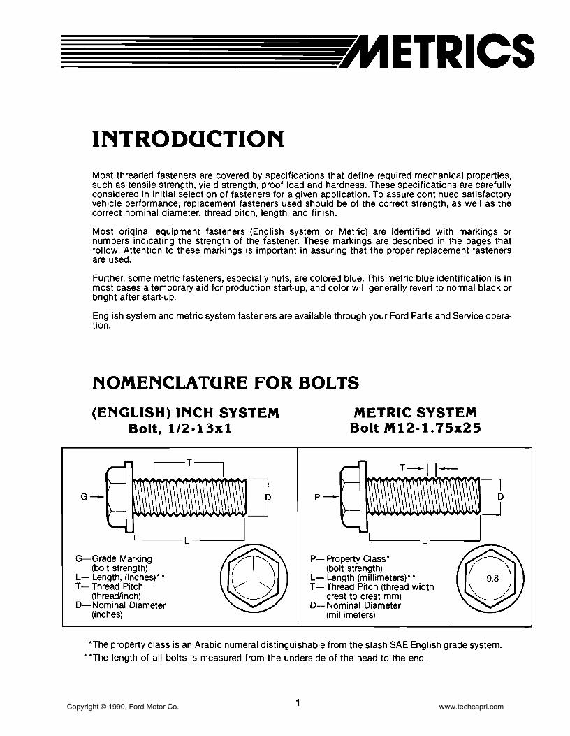
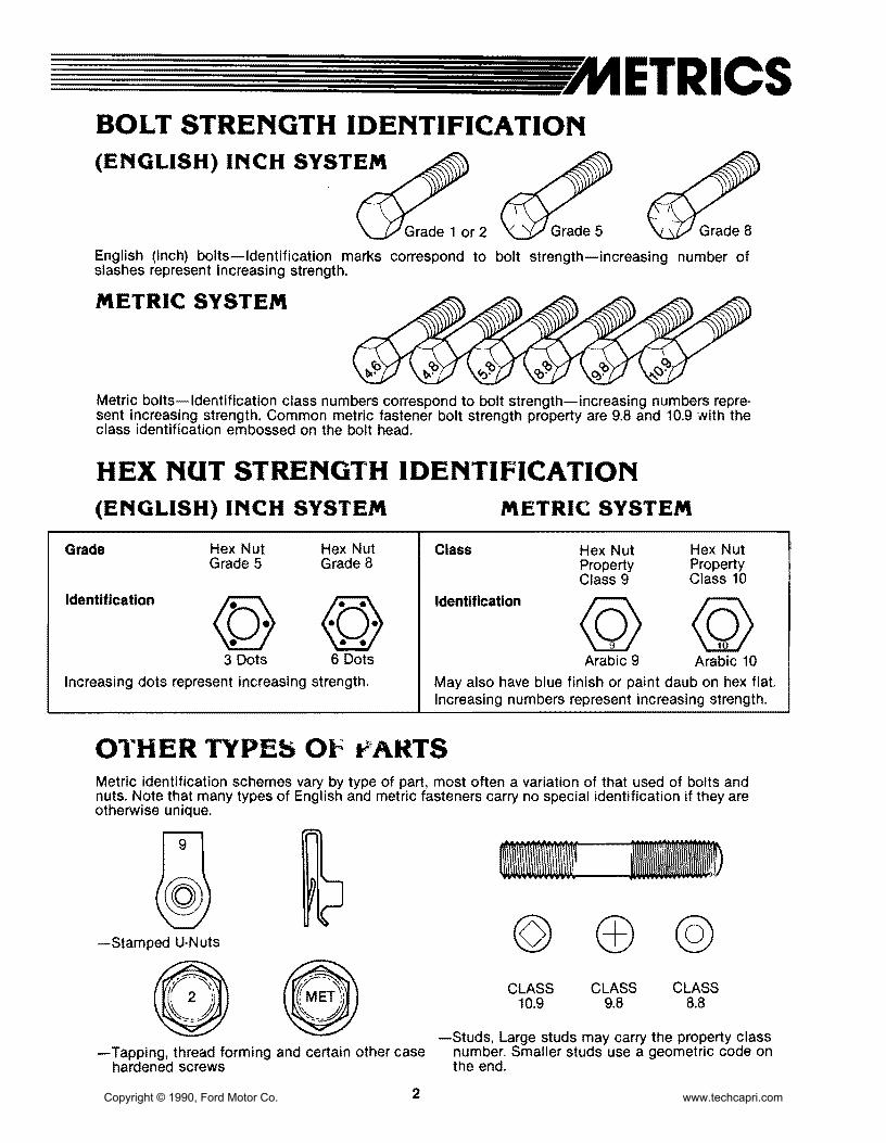
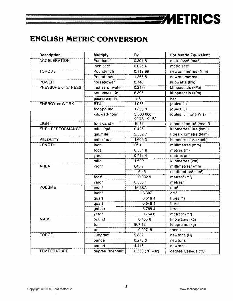
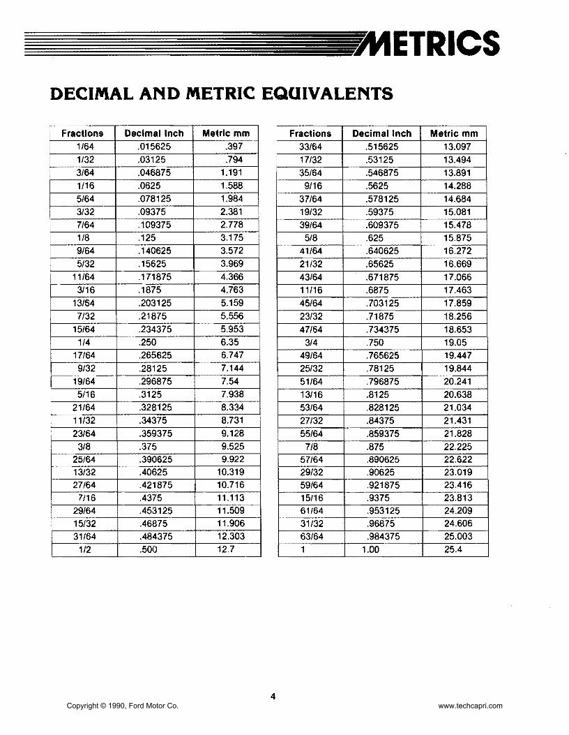
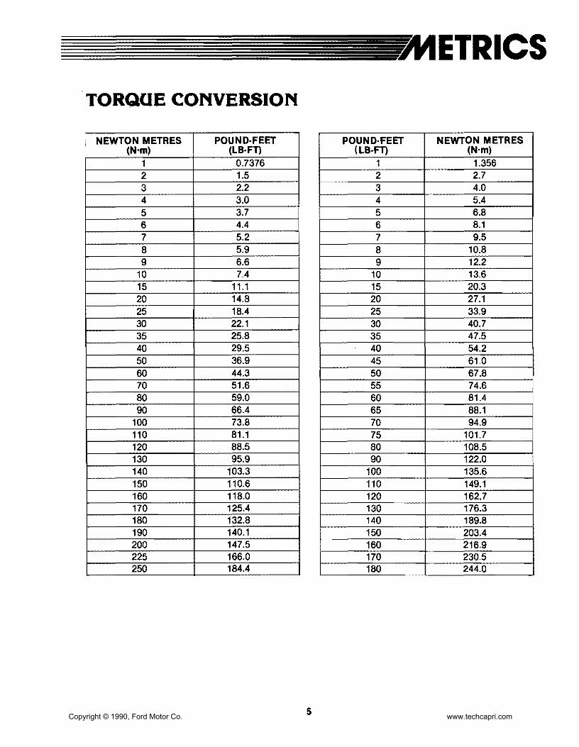

Copyright copy 1990 Ford Motor Co wwwtechcapricom
ALPHABETICAL INDEX
A AIC amp Refrigerant System - Service 36-32-1 Compressor amp Magnetic Clutch 36-32-2 Condenser 36-32-2 Diagnosis amp Testing 36-32-4 Evaporator 36-32-3 Manifold Gauge Set 36-32-17 ReceiverDrier 36-32-2 Refrigerant System Service 36-32-17 Service Precautions 36-32-2 Service Tools 36-32-22 System Charging 36-32-18 System Components 36-32-20 System Discharging 36-32-17 System Evacuating 36-32-17 Thermostatic Expansion Valve TXV 36-32-3
AC-Heater System Manual 36-41-1 AC Auxiliary Fan 36-41-11 AlC Hose 36-41-10 Air Distribution 36-41-3 Airflow 36-41-2 Blower Switch 36-41-1 Condenser 36-41-9 Disassembly amp Assembly 36-41-12 Evaporator Assembly 36-41-10 Operation 36-41-8 Receiver Dryer 36-41-10 Removal amp Installation 36-41-9 Specifications 36-41-13 Temperature Control 36-41-3
Air Cleaner amp Duct Systems 24-41-1 Air Cleaner Assembly 24-41-2 Removal amp Installation 24-41-1 Testing 24-41-1
Alternator - Integral Regulator - External Fan Type 31-17-1
Adjustments 31-17-2 Cleaning amp Inspection 31-17-11 Disassembly amp Assembly 31-17-3 On-Bench Testing 31-17-12 Removal amp Installation 31-17-2 Service Tools 31-17-16 Specifications 31-17-16 Testing 31-17-12 Voltage Regulator 31-17-2
Antennas 35-10-1 Diagnosis amp Testing 35-10-1 Removal amp Installation 35-10-2
Ash Receptacles amp Cigar Lighter 35-40-1 Diagnosis amp Testing 35-40-1 Removal amp Installation 35-40-3
B Batteries 31middot02-1 Battery Capacity Test 31-02-3 Battery Charging 31-02-3 Battery Voltage Check 31-02-1 Cleaning 31-02-6 Maintenance 31-02-5 Removal amp Installation 31-02-4 Service 31-02-4 Service Tools 31-02-6 Testing 31-02-1 Tools 31-02-4
Body 47-02-1 Alignment 47-02-8 Body amp Sheet Metal 47-02-1 Body Panels 47-02-8 Bumper Assembly Front 47-02-2 Bumper Assembly Rear 47-02-3 Bumper Covers 47-02-11 Engine Compartment Underbody Panels 47-02-7 Exterior Parts Flexible - Refinishing 47-02-15 Fender 47-02-6 Inner Splash Shield Front Fender 47-02-5 Removal amp Installation 47-02-2 Repair 47-02-11 Specifications 47-02-15 Splash Shield A-Pillar 47-02-6 Stone Guard Front 47-02-8 Support amp Bracket Front Center 47-02-8
Body Shell Exterior Trim Frame amp Underbody - Service 47-01-1
Adjustments 47-01-2 Appearance Protection 47-01-9 Body Alignment Unitized 47-01-2 Body Dimensions 47-01-3 Body Maintenance 47-01-9 Body Misalignment Check 47-01-2 Body Sealer Types 47-01-2 Body Side Protection Mouldings 47-01-7 Cleaning amp Inspection 47-01-7 Diagnosis amp Testing 47-01-2 Dust amp Water Leaks 47-01-2 Floorpan Plugs amp Grommets 47-01-7 Rattle Elimination 47-01-8 Removal amp Installation 47-01-7
Copyright copy 1990 Ford Motor Co wwwtechcapricom
ALPHABETICAL INDEX
Service Tools 47-01-10 Trim 47-01-8 Underbody Misalignment Check 47-01-2
Brake Booster Vacuum - Dash Mounted 12-50-1 Adjustments 12-50-2 Inspection 12-50-3 Master Cylinder Push Rod Adjustment 12-50-2 Power Booster 12-50-3 Push Rod Length 12-50-2 Removal amp Installation 12-50-3 Service Tools 12-50-3 Vacuum Hose amp Check Valve 12-50-3
Brakes Disc - Single Piston Sliding Caliper - Front 12-20-1
Brake Pads 12-20-3 Brake Rotor Refinishing 12-20-11 Caliper 12-20-5 Disassembly amp Assembly 12-20-8 Overhaul 12-20-10 Removal amp Installation 12-20-3 Rotor 12-20-7 Service Precautions 12-20-3 Service Tools 12-20-12 Specifications 12-20-12
Brakes Disc - Single Piston Sliding Caliper - Rear 12-25-1
Brake Pads 12-25-5 Brakes Parking 12-25-3 Caliper 12-25-8 Disassembly amp Assembly 12-25-11 Removal amp Installation 12-25-5 Rotor 12-25-9
Service Tools 12-25-13 Specifications 12-25-13
Brakes Hydraulic - Service 12-01-1 Adjustments 12-01-30 Brake Booster Functional Test 12-01-11 Brake Pedal 12-01-19 Brake Pedal Height 12-01-14 Brake Pedal Travel Measurement 12-01-14 Brake Shudder 12-01-15 Brake System - Dual 12-01-2 Brake Tube Replacement 12-01-31 Caliper Hose 12-01-21 Diagnosis amp Testing 12-01-6 Disassembly amp Assembly 12-01-22 Disc Brakes Front 12-01-4 Disc Brakes Rear 12-01-4 Hydraulic System 12-01-6 Hydraulic System Bleeding 12-01-30
Inspection 12-01-4 Master Cylinder 12-01-18 Parking Brake 12-01-5 Removal amp Installation 12-01-18 Road Test 12-01-3 Service Tools 12-01-32 Specification 12-01-32 System Priming 12-01-31
c Carpets 45-26-1 Removal amp Installation 45-26-1
Charge Indicator 33-32-1 Diagnosis amp Testing 33-32-1 Removal amp Installation 33-32-3 Voltmeter 33-32-3
Charging System - Service 31-01-1 Diagnosis 31-01-1 Specifications 31-01-8 Testing 31-01-3
Clock 33-15-1 Removal amp Installation 33-15-1
Clutch 16-02-1 Adjustments 16-02-3 Clutch Cable 16-02-5 Clutch Cover 16-02-11 Clutch Disc 16-02-11 Clutch Pedal 16-02-6 Clutch Pedal Height 16-02-3 Clutch Pedal Switch 16-02-5 Clutch Pressure Plate Disc amp Flywheel 16-02-9 Clutch Release Bearing 16-02-11 Flywheel 16-02-12 Hydraulic Clutch Bleeding 16-02-5 Hydraulic Clutch Master Cylinder 16-02-9 Hydraulic Clutch Reservoir Fluid Level 16-02-5 Hydraulic Clutch Slave Cylinder 16-02-9 Pedal Free Play 16-02-4 Removal amp Installation 16-02-5 Service Tools 16-02-15 Specifications 16-02-15
Clutch and Manual Transaxle - Diagnosis 16-01-1 Clutch amp Clutch Pedal 16-01-2 Diagnosis 16-01-2 Gear Noise 16-01-6 Oil Leakage 16-01-6 Transaxle 16-01-4
Copyright copy 1990 Ford Motor Co wwwtechcapricom
ALPHABETICAL INDEX
Compressor amp Clutch 36-39-1 Clutch Pulley Bearing 36-39-7 DCompressor 36-39-2 Maintenance 36-39-1 Pressure Plate Pulley amp Field Coil 36-39-2 Door - Hinge Latch Manual Lock and
Refrigerant Oil Addition 36-39-1 Weatherstrip 44-06-1
Removal amp Installation 36-39-2 Adjustments 44middot06-2
Service Tools 36-39-8 Door Alignment 44middot06-2 Door Bumper 44-06-7
Console Floor 45middot31middot1 Door Bumper Guide 44-06middot8
Console Front 45middot31-2 Door Check Assembly 44middot06middot7
Console Rear 45-31-1 Door Inspection 44-06-2
Removal amp Installation 45-31-1 Door Latch 44middot06middot5
Shifter Boot 45-31-4 Door Latch Release Lever 44-06-5 Door Lock Cylinder 44-06middot6
Convertible 47-07-1 Door Striker 44-06-3
Adjustments 47-07-2 Front Door amp Hinges 44middot06-4
Convertible Top Assembly 47-07-3 Outside Door Handle 44-06middot6
Convertible Top Material 47-07-4 Removal amp Installation 44-06-4
Convertible Top Retainer 47-07-4 Specifications 44-06-9
Convertible Top-to-Windshield Adjustment 47-07-3 Weatherstrip 44-06middot8
Door Glass Fit 47-07-3 Door Lock Power 44-16-1 Latch Effort 47middot07-2 Diagnosis amp Testing 44-16-2 Maintenance 47-07-1 Door Lock Actuator 44-16-5 Moulding Storage Cover-to-Convertible Top 47-07-10 Door Lock Control Switch 44-16-6 Plastic Window Rear 47-07-2 Removal amp Installation 44-16-5 Removal amp Installation 47-07middot3 Specifications 44middot16middot6 Specifications 47-07-17 Storage Compartment Lock Set amp Actuator 47middot07-13 Drive Belts Accessory - Service 27-02middot1
Storage Cover 47-07-15 Adjustments 27middot02-1
Storage Cover Bumpers 47middot07middot15 AlternatorWater Pump Drive Belt Tension 27middot02-1
Storage Cover Hinge 47-07-17 Drive Belt Alternator 27middot02-3
Storage Cover Latch Cables 47-07-13 Drive Belt Power Steering amp AlC 27middot02-4
Storage Cover Pivot Caps 47middot07middot12 Power Steering amp AC Drive Belt Tension 27-02middot2
Storage Cover Strikers 47-07-14 Removal amp Installation 27-02middot3
Storage Cover Support 47middot07-16 Storage Cover Trim 47-07-15 Storage Top Latch 47middot07-13 E Weatherstrip Covertible Top-to-Windshield 47-07middot10 Weatherstrip Rear Seat-tomiddotStorage Cover 47-07-11 Engine Coolant Temperature Indicating System 33-25-1 Weatherstrip Storage Covermiddotto-Body 47-07-11 Diagnosis amp Testing 33-25-1 Weatherstrips Convertible Top Side 47-07-10 Removal amp Installation 33middot25-5 Window Rear 47-07-4 Temperature Sending Unit 33-25-5
Cooling System - Service 27-01-1 Engine 16L 21middot10-1 Coolant Condition Check 27-01-6 Camshaft 21middot10-14 Coolant Draining amp Replacement 27-01-7 Camshaft Seals 21-10-22
Cooling System Flush Procedure 27-01-7 Connecting Rod 21-10-39 Cooling System Pressure Test 27-01-5 Core Plugs 21-10-23 Diagnosis amp Testing 27-01middot2 Crankshaft 21-10-39 Pressure Cap Testing 27-01middot4 Crankshaft End Play 21-10middot40 Service Tools 27-01-8 Crankshaft Main Bearings amp Connecting Thermostat Testing 27-01middot6 Rod Bearings 21-10-16
Copyright copy 1990 Ford Motor Co wwwtechcapricom
ALPHABETICAL INDEX
Crankshaft Oil Clearance 21-10-40 Diagnosis amp Testing 27middot10middot2 Crankshaft Oil Seal Front 21-10-23 Removal amp Installation 27-10-9 Crankshaft Oil Seal Rear 21middot10-23 Specifications 27-10-10 Cylinder Block 21-10-34
Fuel Filters 24-51-1 Cylinder Block Flatness 21-10middot35
Inmiddot Line Filter 24-51-1 Cylinder Bores 21-10-36
In-Tank Filter 24-51middot1 Cylinder Head 21-10-42
RemOVAl amp Installation 24-51-1 Disassembly amp Assembly 21-10-24 Engine Mount Front 21middot10middot9 Fuel Injection Electronic 24-05-1 Engine Mount Rear 21middot10middot9 Adjustments 24-05-13 Engine Mounts RH 21-10-9 Airflow 24-05-8 Exhaust Manifold 21middot10-18 Air Induction System 24-05-6 HLA 21-10-46 BAC Valve 24-05-16 Intake Manifold 21-10-17 BP Sensor 24-05-16 Oil Pan 21-10middot19 Bypass Air Control Valve 24-05-9 Oil Pump 21-10-20 Diagnosis amp Testing 24-05-13 Piston amp Connecting Rod Assembly 21-10-21 Electronic Control Assembly 24-05-14 Pistons Piston Rings amp Piston Pins 21-10-37 Electronic Engine Control 24-05middot10 Removal amp Installation 21-10-2 Engine Coolant Temperature Sensor 24-05-15 Service Procedures 21-10-34 Fuel Injectors 24-05-15 Service Tools 21-10-49 Fuel System 24-05-4 Specifications 21-10-47 Idle Speed 24-05-13 Subassemblies 21middot10-32 Oxygen Sensor 24-05-16 Timing Belt 21-10-12 Removal amp Installation 24-05-13 Valve Stem Seals 21-10-19 Service Tools 24-05-17
Specifications 24-05-17Engine Gasoline - Service 21-01-1
Throttle Body 24-05-13 Camshaft Lobe Lift 21-01-4
Throttle Position Sensor 24-05-15 Compression Test 21-01-3
Turbo Boost Gauge 24middot05-16 Diagnosis amp Testing 21-01-2
Vane Air Flow Meter 24-05-14 Emissions Calibration Label 21-01-2 Engine Identification 21-01-2 Fuel Level Indicating System 33-20-1 Engine Oil Leaks 21middot01-2 Diagnosis amp Testing 33-20middot1 Exhaust Emission Control System 2101-2 Fuel Gauge 33-20-3 Positive Closed-Type Crankcase Ventilation Fuel Tank Sending Unit 33-20middot3
System 21-01-2 Removal amp Installation 33-20-3 Service Tools 21middot01-5
Fuel Pump - Electric 24-35-1 Valve Train Analysis 21-01-4
Control Circuit 24-35-2 Exhaust System 26-01-1 Fuel Pump Relay 24-35-4 Diagnosis 26-01-1 Pressure Regulator 24-35-3 Exhaust Leakage or Noise 26-01-1 Removal amp Installation 24-35-3 Removal amp Installation 26-01-4 Fuel System - Service 24-01-1 Restricted Exhaust System 26-01-3
F
Air Cleaner 24-01-2 Cleaning amp Inspection 24-01-2 Fuel Injection Electronic 24-01-2 Testing amp Adjustments 24-01-2
Fuel Tanks and Lines 24-50-1
Fan Electro-Drive Cooling 27-10-1 Fuel Filler Door 24-50-3
Coolant Temperature Switch 27-10middot9 Fuel Filler Neck 24-50-5
Cooling Fan 27-10middot9 Fuel System Pressure Relief 24-50-2
Cooling Fan Motor 27-10-9 Fuel Tank 24-50-4
Cooling Fan Relay 27-10-10 Removal amp Installation 24-50-2
Copyright copy 1990 Ford Motor Co wwwtechcapricom
ALPHABETICAL INDEX
Fuses amp Circuit Breakers 34-50-1 Fuse link 34-50-4 Fuse link Charging System 34-50-3
Fuse Panel Interior 34-50-3 Main Fuse Box 34-50-3 Removal amp Installation 34-50-3
G Glass Stationary - Windshield 43-02-1 Mouldings Front Window 43-02-1 Removal amp Installation 42-02-1 Windshield 43-02-4
H Halfshafts amp CV Joints - Front-Wheel Drive 15-22-1 Diagnosis 15-22-5 Disassembly amp Assembly 15-22-11 Halfshaft Handling 15-22-4 J oint shaft 15-22-11 Removal amp Installation 15-22-8 Rzeppa CV Joint 15-22-13 Service Tools 15-22-22 Specifications 15-22-22 Tripo Joint 15-22-19
Hardtop Removable 47-10-1 Exterior Mouldings Side amp Rear 47-10-4 Hardtop Front Attachment Bracket 47-10-5 Hardtop Side amp Rear Windows 47-10-6 Hardtop-to-Vehicle Weatherstrip 47-10-4 Headlining 47-10-6 Mouldings Roof 47-10-4 Removal amp Installations 47-10-1 SideRear Attachments 47-10-5 Side Window Opening Weatherstrip 47-10-4 Trim Panel Rear 47-10-3 Trim Panels Interior Side 47-10-3 Window Retainer Moulding Side 47-10-3 Wiring Harness 47-10-5
Headlamp System 32-02-1 Adjustments 32-02-15 Diagnosis amp Testing 32-02-6 Fog Lamp 32-02-18 Fog Lamp Switch 32-02middot18 Headlamp Aim 32middot02middot15 Headlamp Assembly 32middot02middot16 Headlamp Motor 32middot02middot16 Headlamp Motor Switch 32middot02middot18 Headlamp Switch 32middot02middot17 High BeamFlashmiddottomiddotPass Switch 32middot02middot18
High Beam Indicator Lamp Bulb 32-02middot18 Linkage 32middot02-17 Removal amp Installation 32-02middot15
Heater amp Power Ventilation System 36-10middot1 Adjustments 36-10-15 Air Distribution 36middot10-2 Air Door Control Cable 36-10-16 Airflow 36-10middot1 Air Inlet Duct 36middot10middot26 Blower Case Assembly 36-10-19 Blower Motor 36-10-18 Blower Motor Resistor 36-10-18 Blower Switch 36-10middot17 Control Cables 36middot10-17 Defroster Ducts 36-10middot24 Defroster Tubes amp Side Demister Tubes 36middot10middot25 Diagnosis amp Testing 36middot10middot5 Function Selector Cable 36middot10middot15 Function Selector Rod 36-10-15 Heat Ducts Rear Seat 36middot10-25 Heater Case 36middot10-20 Heater Control Panel 36-10-16 Heater Core 36-10-22 Heater Hoses 36-10-23 Heater Tube LH 36middot10-27 Instrument Panel Ducts 36middot10-26 Register LH Side amp Center 36middot10middot24 Register RH Side 36-10-24 Removal amp Installation 36-10-16 Temperature Control 36-10middot2 Temperature Control Cable 36-10-15
Heating System - Service 36-01-1 Bench Test 36-01-3 Diagnosis 36-01-4 Heater Core 36-01middot2 Heater Core Leak Test 36middot01middot3 Heating Systems amp Control Doors 36middot01middot2 Pressure Test 36middot01-3 Service Tools 36middot01middot5 Testing 36-01-2
HOisting Jacking amp Towing 10middot04middot1 Hoisting amp Jacking 10middot04middot1 TmiddotHooks Front 10middot04-5 TmiddotHooks Rear 10middot04middot5 Towing 10-04-3 Towing Procedures 10-04-4 Towing Slings 10middot04middot3
Hood Hinge amp latch 44-08-1 Adjustments 44-08-2 Hood 44-08middot8 Hood Alignment 44-08-2 Hood Bumpers 44-08middot3 Hood Hinge 44middot08-5 Hood Latch 44middot08middot5 Copyright copy 1990 Ford Motor Co wwwtechcapricom
ALPHABETICAL INDEX
Hood Release Cable 44-08-6 Instrument Panel amp Glove Compartment 45-61-1 Hood Safety Latch 44-08-6 Instrument Cluster Bezel 45-61-1 Hood Seals 44-08-5 Instrument Panel Assembly 45-61-2 Hood Support Rod 44-08-7 Removal amp Installation 45-61-1 Hood Weatherstrip 44-08-4 Latch Adjustments 44-08-2
Removal amp Installation 44-08-3
Horns 35-80-1 Adjustments 35-80-3 Lamps Interior 32-60-1 Diagnosis amp Testing 35-80-1 Diagnosis amp Testing 32-60-2 Horn Relay 35-80-4 Door Switch 32-60-7 Horn Switch 35-80-4 LampBlub Glove Compartment 32-60-8 Removal amp Installation 35-80-3 Lamp Dome 32-60-6
Lamps Courtesy 32-60-7
LensBulb Cargo Lamp 32-60-9 Removal amp Installation 32-60-6
Lamps - Parking Rear and Marker 32-20-1 Identification Codes 10-01-1 Combination LampBulb Replacement 32-20-7 Anti-Theft Labels 10-01-2 Combination Lamp Rear 32-20-6 Exteriorllnterior Labels 10-01-4 Diagnosis amp Testing 32-20-2 Label Locations 10-01-3 Hi-Mount Brakelamp 32-20-7 Official Vehicle Identification Number 10-01-1 License Plate LampBulb 32-20-7 Replacement VIN Label 10-01-2 Parking LampBulb Front 32-20-6 Vehicle Certification Label 10-01-2 Removal amp Installation 32-20-6
Side Marker LampBulb Front 32-20-6Ignition Switch 31-20-1
Side Marker Lamps Rear 32-20-8Ignition Lock Tumbler 31-20-2
Stop lamp Switch 32-20-8Non-Functioning Locks 31-20-3 Removal amp Installation 31-20-2 Lubrication Points and Lubricant Switch Blade-Type 31-20-1 Specifications 10-03-1 Testing 31-20-1 Lubrication 10-03-1
Specifications 10-03-3Ignition System Service 23-03-1 Diagnosis amp Testing 23-03-2 Luggage Compartment - Door Hinge Latch Disassembly amp Assembly 23-03-4 Lock and Weatherstrip 44-10-1 Distributor 23-03-4 Adjustments 44-10-1 Distributor Cap amp Rotor 23-03-2 Alignment 44-10-1 Ignition Coil 23-03-3 Door 44-10-3
Operation 23-03-2 Door Bumpers 44-10-8 Gas Lift Cylinders 44-10-6Removal amp Installation 23-03-2
Secondary Ignition Wires 23-03-2 Glove Compartment 44-10-9
Spark Plugs 23-03-3 Hinge 44-10-5 Latch 44-10-5
Instrument Cluster 33-01-1 Latch Glove Compartment 44-10-10 Diagnosis amp Testing 33-01-4 Lock Cylinder 44-10-5 Disassembly amp Assembly 33-01-12 Lock Glove Compartment 44-10-10 Heater Control Panel Bulb 33-01-11 Removal amp Installation 44-10-2 Instrument Cluster Bulbs 33-01-11 Spoiler 44-10middot8 Panel Dimmer SWitch 33-01-11 Striker 44-10-2 Removal amp Installation 33-01-10 Striker Glove Compartment 44-10-9 Speed Sensor 33-01-11 Weatherstrip 44-10-7
Copyright copy 1990 Ford Motor Co wwwtechcapricom
ALPHABETICAL INDEX
M Mirrors Exterior 42-25-1 Diagnosis amp Testing 42-25-2 Mirror Assembly 42-25-7 Removal amp Installation 42-25-7 Switch 42-25-7
Mirrors Inside 42-21-1 Removal amp Installation 42-21-1
Mouldings 45-16-1 Convertible Top Retainer 45-16-1 Door Scuff Plate amp Side Trim 45-16-4 Hardtop Header Trim Cover 45-16-3 Removal amp Installation 45-16-1 Specifications 45-16-4 Windshield Moulding Side 45-16-2 Windshield Moulding Upper 45-16-2
N Noise Vibration and Harshness 18-01-1 Diagnosis ampTesting 18-01-6 Diagnostic Theory 18-01-1 Glossary 18-01-2 Non-Transaxle Noise 18-01-4 NVH Diagnosis 18-01-4 Road Test 18-01-4 Service Tools 18-01-12 Transaxle Noise 18-01-4
o Oil Pressure Indicating Svstem 33-34-1 Diagnosis amp Testing 33-34-1 Oil Pressure Sending Unit 33-34-4 Removal amplnstallaon 33-34-4
p I Parking Brake Cable Actuated shy
Rear Wheels 12-70-1 Adjustment 12-70-2 Cable Parking Brake 12-70-2
Cables Long 12-70-4 Parking Brake Lever 12-70-3 Removal amp Installation 12-70-3
R Radiator 27-03-1 Cleaning External amp Internal 27-03-13 Leak Testing 27-03-13 Oil Cooler Transfer or Replacement 27-03-13 Radiator Core 27-03-14 Radiator Tank 27-03-5 Removal amp Installation 27-03-3 Service Procedures 27-03-14 Service Tools 27-03-17 Testing 27-03-13 Thermostat 27-03-5 Water Pump 27-03-4
Restraint Svstem - Supplemental Air Bag 41-58-1 Air Bag Clockspring 41-58-32 Air Bag Module 41-58-31 Backup Power Supply 41-58-32 Deactivating the System 41-58-29 Deployed Air Bag 41-58-28 Descriptions 41-58-1 Diagnosis ampTesting 41-58-4 Diagnostic Assembly 41-58-31 Disposal Procedures 41-58-27 Live Air Bags 41-58-27 Operation 41-58-4 Parts Replacement 41-58-26 Reactivating the System 41-58-29 Removal amp Installation 41-58-29 Sensor Front Center 41-58-29 Sensor Front Left or Right 41-58-30 Sensor Rear 41-58-30 Service Precautions 41-58-27 Specifications 41-58-32 Undeployed Air Bag Faulty 41-58-28
I s Scheduled Maintenance 10-02-1 Emission Control Information Decal 10-02-1 Maintenance Schedules 10-02-3
Seat and Shoulder Safetv Belts 41-50-1 Belt Webbing 41-50-5
Copyright copy 1990 Ford Motor Co wwwtechcapricom
ALPHABETICAL INDEX
Buckle Assembly Front 41-50-2 Cleaning 41-50-5 Major Service Operations 41-50-4 Removal amp Installation 41-50-2 Retractor amp Harness Assembly Front 41-50-2 Retractor amp Harness Assembly Rear 41-50-3 Safety Belt Maintenance 41-50-4 Seat Buckle Rear 41-50-4
Seat Child Restraint - Tether Attachment 41-52-1 Installation 41-52-1
Seats Front 41-04-1 Head Restraint amp Cover 41-04-7 Lumbar Support 41-04-8 Reclining Mechanisms 41-04-7 Removal amp Installation 41-04-1 Seat Back 41-04-4 Seat Back Cover amp Cushion 41-04-5 Seat Cover amp Cushion 41-04-3 Seat Height Adjuster LH Seat 41-04-9 Seat Height Adjustment Mechanism Control
Assembly LH Seat 41-04-9 Specifications 41-04-10
Seats Rear 41-20-1 Actuator Lock Set 41-20-8 Cable Actuator 41-20-7 Latch Seat Back 41-20-5 Latch Cable Seat Back 41-20-6 Removal amp Installation 41-20-1 Seat Back amp Cover 41-20-1 Seat Cushion 41-20-4
Shift Control Linkage 17-02-1 Adjustments 17-02-2 Disassembly amp Assembly 17-02-7 Gear Selector 17-02-7 Gear Selector Assembly 17-02-5 Removal amp Installation 17-02-4 Shift Control Cable 17-02-4 Specifications 17-02-10
Sound Systems 35-01-1 AMFM Multiplex Radio - ESR 35-01-3 AMFM Multiplex with Cassette Player 35-01-4 Cassette Tape Player 35-01-3 Diagnosis amp Testing 35-01-6 Premium Sound 35-01-2 Premium Sound Amplifier 35-01-18 Radio Reception 35-01-2 Removal amp Installation 35-01-17
Speakers 35-30-1 Diagnosis 35-30-1 Door Mounted Speakers 35-30-2
Rear Seat Speakers 35-30-3 Removal amp Installation 35-30-2
Speed Control System 37-01-1 Actuator 37-01-11 Actuator Cable 37-01-9 Adjustments 37-01-9 CableActuator Assembly 37-01-10 Clutch Pedal Height 37-01-9 Control Module 37-01-10 Control Switches 37-01-9 Diagnosis amp Testing 37-01-3 Removal amp Installation 37-01-9
Speedometer 33-10-1 Assembly 33-10-4 Diagnosis amp Testing 33-10-1 Removal amp Installation 33-10-3 Speedometer Cable Core 33-10-4 Speedometer Driven Gear 33-10-4
Starter Positive Engagement 28-02-1 Disassembly amp Assembly 28-02-5 Jump Starting 28-02-2 Pinion Depth Adjustment 28-02-3 Removal amp Installation 28-02-5 Service Tools 28-02-13 Specifications 28-02-13 Starter Motor No-Load Test 28-02-4 Testing 28-02-2
Starting System - Service 28-01-1 Diagnosis amp Testing 28-01-2 Neutral Safety Switch 28-01-7 On-Vehicle Inspection 28-01-2 Removal amp Installation 28-01-7 Service Tools 28-01-7 Voltage Drop Tests 28-01-3
Steering Column 13-04-1 Air Bag Module 13-04-2 Component Fasteners 13-04-2 Disassembly amp Assembly 13-04-6 Intermediate Shaft 13-04-4 Removal amp Installation 13-04-3 Specifications 13-04-10 Steering Column Support Brackets 13-04-5 Steering Wheel 13-04-3 Turn Signal Cancel Cam Service 13-04-9
Steering Gear Power Rack-and-Pinion 13-46-1 Adjustments 13-46-5 Disassembly amp Assembly 13-46-7 Dust Boot 13-46-6 Rack Yoke Preload 13-46-5 Removal amp Installation 13-46-6
Copyright copy 1990 Ford Motor Co wwwtechcapricom
ALPHABETICAL INDEX
Service Tools 13-46-17 Specifications 13-46-17 Tie Rod End 13-46-6
Steering Power - Hoses 13-55-1 High Pressure Hose 13-55-2 PressureReturn Tubing 13-55-3 Removal amp Installation 13-55-2 Return Hose 13-55-3
Steering Pump Power 13-51-1 Adjustments 13-51-2 Cleaning amp Inspection 13-51-6 Disassembly amp Assembly 13-51-4 Drive Belt Tension 13-51-2 Fluid Level Check 13-51-2 Flushing Power Steering System 13-51-6 Power Steering Pump 13-51-4 Pressure Regulator Valve 13-51-3 Pressure Switch 13-51-3 Pump Assembly 13-51-3 Removal amp Installation 13-51-3 Start-Up Procedure 13-51-2 Testing 13-51-2
Steering - Service 13-01-1 Pump Flow amp Pressure Tests 13-01-4 Service Tools 13-01-7 Specifications 13-01-7 Steering Wheel Free Play 13-01-5 Testing 13-01-2
Suspension Front 14-10-1 Ball Joint 14-10-2 Control Arm 14-10-5 Disassembly amp Assembly 14-10-5 Removal amp Installation 14-10-2 Se+vice Tools 14-10-6 Specifications 14-10-6 Strut amp Spring 14-10-3
Suspension Rear 14-32-1 Control Arms amp Trailing Arm 14-32-7 Removal amp Installation 14-32-4 Service Tools 14-32-11 Specifications 14-32-11 Spindle 14-32-6 Strut amp Spring Rear 14-32-4
Suspension - Service 14-01-1 Adjustments 14-01-6 Ball Joints 14-01-4 Camber 14-01-6 Control Arms amp Stabilizers 14-01-4 Diagnosis amp Testing 14-01-1
Heights 14-01-3 Specifications 14-01-9 Steering Wheel Centering 14-01-8 Steering Wheel Play 14-01-4 Struts 14-01-3 Tie Rods 14-01-4 Toe Rear 14-01-7 Toe In Front 14-01-6 Wheel Alignment 14-01-4
T Tachometer 33-11-1 Diagnosis amp Testing 33-11-1 Removal amp Installation 33-11-5
Throttle Linkage 24-60-1 Adjustments 24-60-1 Free Play 24-60-1 Removal amp Installation 24-60-2 Throttle Cable 24-60-2 Wide-Open Throttle Position 24-60-1
Transaxle Automatic - 4EAT 17-27-1 2-3 Accumulator 17-27-80 3-4 Accumulator 17-27-77 Adjustments 17-27-29 Bearing Housing 17-27-94 Bearing Locator 17middot27middot96 Bearing Preload amp Shim Selection 17middot27middot31 BearingStator Support 17-27-95 Cleaning amp Inspection 17-27-97 Clutch Assemblies 17middot27middot68 Diagnosis amp Testing 17-27middot4 Differential 17middot27middot90 Disassembly amp Assembly 17-27middot42 Idler Gear 17middot27-92 Kickdown Cable 17middot27middot29 Major Service Operations 17-27-29 Oil Cooler 17middot27-31 Oil Pump 17-27-63 One-Way Clutch amp Plantary Carrier Assembly 17-27-76 Output Gear 17-27middot91 Removal amp Installation 17-27-36 Service Tools 17middot27-102 Small Sun Gear amp One-Way Clutch 17-27-74 Specifications 17-27-100 Subassemblies 17-27-63 Torque Converter 17-27-98 Transaxle Fluid Level Check 17-27-29 Valve Body 17-27-80
Copyright copy 1990 Ford Motor Co wwwtechcapricom
ALPHABETICAL INDEX
Transaxle Automatic - Service 17-01-1 Description 17-01-1
Transaxle Manual- 5-Speed - Non-Turbo Engine 16-37-1
Cleaning amp Inspection 16-37-43 Clutch Housing 16-37-25 Differential 16-37-37 Disassembly amp Assembly 16-37-17 Gearshift Linkage 16-37-13 General Service Procedures 16-37-15
Input Shaft 16-37-43 Main Shaft 16-37-44 Main Shift Rail 16-37-40
Operation 16-37-2 Removal amp Installation 16-37-5 Service Tools 16-37-46 Shift Linkage 16-37-5 Specifications 16-37-46 Subassemblies 16-37-24 Transaxle Fluid Level Check 16-37-15 Transaxle Housing 16-37-30 Transaxle Oil Seal 16-37-10
Transaxle Manual - 5-Speed - Turbo Engine 16-38middot1 Differential 16-38-39 Differential Shim Selection 16-38-63 Disassembly amp Assembly 16middot38-18 Gear amp Shaft 16-38-35 Gearshift Linkage 16-38-7 Input Gear Shaft Shim Selection 16-38-61 Input Shaft Bearing 16-38-57 Main Shaft Shim Selection 16-38-58 Operation 16-38-3 Removal amp Installation 16-38-7 Service Procedures 16-38-17 Service Tools 16-38middot66 Shift Linkage 16middot38middot6 Specifications 16middot38-65 Subassemblies 16middot38middot35 Transaxle Fluid Level Check 16middot38middot17 Transaxle Oil Seal 16-38middot9
Trim Panels Interior 45middot03middot1 Convertible Top Storage Compartment 45middot03middot13 Cowl Side Trim Panel 45-03-8
Door Trim Panels 45middot03middot1
Floor Panels Luggage Compartment 45middot03-15 Luggage Compartment Rear Trim Panels 45-03-14 Luggage Compartment Side Trim Panels 45middot03-14
Rear Quarter Trim Panels 45middot03-8
Removal amp Installation 45middot03-1 Watershield 45-03-7
Turbo Boost Indicating System 33middot36middot01 Boost Gauge 33middot36middot3 Boost Gauge Sensor 33-36middot3 Diagnosis amp Testing 33-36middot1
Removal amp Installation 33middot36middot3
Turbocharger 24middot45middot1 Air-FuelExhaust Gas Flow 24-45-2 Bearing Clearance Check 24-45-9 Boost Control Automatic 24middot45-2 Coolant Return Hose 24middot45-7
Coolant Supply Hose amp Fitting 24-45-7 Diagnosis amp Testing 24middot45middot9 Intercooler 24middot45middot7 Intercooler Hoses 24middot45middot8 Lubrication 24middot45middot1 Oil Return Hose 24middot45middot7 Oil Supply Line 24middot45middot6 Operation 24middot45-2 Overboost Pressure Switch 24middot45-8 Removal amp Installation 24-45-2 Specifications 24-45-12
Turn Signal and Hazard Flasher 32middot40-1 Diagnosis amp Testing 32middot40middot2
Hazard Flasher Unit 32middot40-7 Removal amp Installation 32middot40middot6
SWitch Assembly 32middot40middot6 Turn Signal Flasher Unit 32middot40middot7
Wiper Switch amp Turn Signal High Beam Lever 32middot40middot6
w Warning Indicator 33-45middot1 Brake Indicator 33middot45-1 Diagnosis amp Testing 33middot45middot3 Engine Warning Lamp 33-45middot1 High Beam Indicator 33middot45middot2 Instrument Panel Lamps 33middot45middot1 Parking Brake Switch 33middot45middot10 Removal amp Installation 33middot45middot10
Safety Belt Indicator 33middot45middot1 Safety Belt Switch 33middot45middot11 Warningllndicator Lamp Bulbs 33middot45middot10
Wheel Hubs and Bearings - Front 11middot10-1 Bearing Front 11-10middot2 Brake RotorlWheel Hub 11-10-9
Diagnosis 11-10-2
Disassembly amp Assembly 11-10middot9 Removal amp Installation 11middot10middot3
Copyright copy 1990 Ford Motor Co wwwtechcapricom
ALPHABETICAL INDEX
Service Tools 11-10-15 Removal amp Installation 42-08-6
Specifications 11-10-15 Window Channel Rear 42-08-11
Steering KnuckleBearings 11-10-13 Window Channels 42-08-6
Wheel HubSteering Knuckle Assembly 11-10-3 Window Glass 42-08-7
Window Guide 42-08-7 Wheel Hubs amp Bearings - Rear 11-15-1
Window Stop 42-08-6 Adjustments 11-15-6
Bearing Preload 11-15-6 Windshield Washers 35-70-1
Bearing Races 11-15-9 Diagnosis amp Testing 35-70-2
Brake RotorBearing Hub Assembly 11-15-7 Nozzles amp Hose 35-70-4
Grease SealBearings 11-15-8 Pump 35-70-4
Inspection 11-15-2 Removal amp Installation 35-70-4
Removal amp Installation 11-15-7 Reservoir amp Washer Pump 35-70-4
Specifications 11-15-9 Washer Switch 35-70-5
Wheels and Tires - Service 11-01-1 Windshield Wipers 35-60-1
Diagnosis 11-01-5 Adjustments 35-60-8
Maintenance 11-01-2 Diagnosis amp Testing 35-60-3
Road Test 11-01-6 Linkage 35-60-10
Service 11-01-10 Removal amp Installation 35-60-8
Service Tools 11-01-14 Specifications 35-60-10
Specifications 11-01-13 Windshield Wiper Arm Position 35-60-8
Tire and Wheel Balance 11-01-11 Wiper Arm 35-60-9
Tire Inflation 11-01-3 Wiper Blade 35-60-8
Tire Lead 11-01-9 Wiper Motor 35-60-9
Vibration amp Roughness 11-01-6 Wiper Switch amp Lever 35-60-10
Wheel Lug Nuts 11-01-2 Wiring Harness - Connectors 34-01-1
WheelTire Runout 11-01-9 Connectors 34-01-1
Window Glass amp Mechanisms - Service 42-01-1 Removal amp Installation 34-01-1
Lubrication 42-01-1 Wire Ends 34-01-2
Wiring Harnesses 34-26-1Window Rear - Defroster 36-86-1 Dash Panel 34-26-5Bus Bar Terminal Repair 36-86-7 Door 34-26-6Diagnosis amp Testing 36-86-2 Engine Compartment 34-26-3Major Service Operations 36-86-6 Floor 34-26-7ONOFF Switch 36-86-7 Ground Cable 34-26-2Removal amp Installation 36-86-7 Hardtop 34-26-6
Windows Power 42-08-1 Instrument Panel 34-26-6
Adjustments 42-08-6 Lamps Rear 34-26-9 Diagnosis amp Testing 42-08-2 Luggage Compartment Lid 34-26-9 Door Quarter Window 42-08-11 Quarter Panel 34-26-8 Door Window Switch 42-08-6 Removal amp Installation 34-26-1 Motor Regulator Assembly 42-08-9 Starter amp Alternator Cables 34-26-3
Copyright copy 1990 Ford Motor Co wwwtechcapricom
Copyright copy 1990 Ford Motor Co wwwtechcapricom
We Want To Hear FroID youl------ Do you have any suggestions for improving this publication
FOR EXAMPLE
bull Did you find any errors
If yes Manual ________________Volume_____Page___
bull Were any subjects not covered
If yes Please describe _________________________
bull Were any sections confusing or hard to understand
If yes Manual ________________Volume_____ Page___
Please comment
bull Could you quickly find what you need Yes _________ No
Suggestions
bull Tell us who you are
Name _______________________________________________________________
Address ________________________________________
Position _____________________________ Company ______________________
It is most helpful if you would enclose a copy of each page marked with your suggestions
Copyright copy 1990 Ford Motor Co wwwtechcapricom
------------------------------------------------------------------------
DO NOT STAPLE - USE TRANSPARENT TAPE
NO POSTAGE NECESSARY IF MAILED
IN THE UNITED STATES
111111
BUSINESS REPLY MAIL FIRST CLASS PERMIT NO 400 DEARBORN MICH
POSTAGE WILL BE PAID BY ADDRESSEE
Ford Parts and Service Division Advanced Service Engineering Fairlane Technical Center PO Box 1902 Dearborn Michigan 48121
Copyright copy 1990 Ford Motor Co wwwtechcapricom
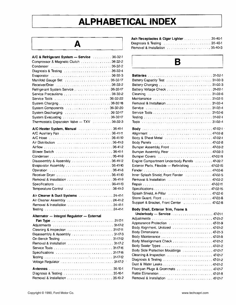
ALPHABETICAL INDEX
A AIC amp Refrigerant System - Service 36-32-1 Compressor amp Magnetic Clutch 36-32-2 Condenser 36-32-2 Diagnosis amp Testing 36-32-4 Evaporator 36-32-3 Manifold Gauge Set 36-32-17 ReceiverDrier 36-32-2 Refrigerant System Service 36-32-17 Service Precautions 36-32-2 Service Tools 36-32-22 System Charging 36-32-18 System Components 36-32-20 System Discharging 36-32-17 System Evacuating 36-32-17 Thermostatic Expansion Valve TXV 36-32-3
AC-Heater System Manual 36-41-1 AC Auxiliary Fan 36-41-11 AlC Hose 36-41-10 Air Distribution 36-41-3 Airflow 36-41-2 Blower Switch 36-41-1 Condenser 36-41-9 Disassembly amp Assembly 36-41-12 Evaporator Assembly 36-41-10 Operation 36-41-8 Receiver Dryer 36-41-10 Removal amp Installation 36-41-9 Specifications 36-41-13 Temperature Control 36-41-3
Air Cleaner amp Duct Systems 24-41-1 Air Cleaner Assembly 24-41-2 Removal amp Installation 24-41-1 Testing 24-41-1
Alternator - Integral Regulator - External Fan Type 31-17-1
Adjustments 31-17-2 Cleaning amp Inspection 31-17-11 Disassembly amp Assembly 31-17-3 On-Bench Testing 31-17-12 Removal amp Installation 31-17-2 Service Tools 31-17-16 Specifications 31-17-16 Testing 31-17-12 Voltage Regulator 31-17-2
Antennas 35-10-1 Diagnosis amp Testing 35-10-1 Removal amp Installation 35-10-2
Ash Receptacles amp Cigar Lighter 35-40-1 Diagnosis amp Testing 35-40-1 Removal amp Installation 35-40-3
B Batteries 31middot02-1 Battery Capacity Test 31-02-3 Battery Charging 31-02-3 Battery Voltage Check 31-02-1 Cleaning 31-02-6 Maintenance 31-02-5 Removal amp Installation 31-02-4 Service 31-02-4 Service Tools 31-02-6 Testing 31-02-1 Tools 31-02-4
Body 47-02-1 Alignment 47-02-8 Body amp Sheet Metal 47-02-1 Body Panels 47-02-8 Bumper Assembly Front 47-02-2 Bumper Assembly Rear 47-02-3 Bumper Covers 47-02-11 Engine Compartment Underbody Panels 47-02-7 Exterior Parts Flexible - Refinishing 47-02-15 Fender 47-02-6 Inner Splash Shield Front Fender 47-02-5 Removal amp Installation 47-02-2 Repair 47-02-11 Specifications 47-02-15 Splash Shield A-Pillar 47-02-6 Stone Guard Front 47-02-8 Support amp Bracket Front Center 47-02-8
Body Shell Exterior Trim Frame amp Underbody - Service 47-01-1
Adjustments 47-01-2 Appearance Protection 47-01-9 Body Alignment Unitized 47-01-2 Body Dimensions 47-01-3 Body Maintenance 47-01-9 Body Misalignment Check 47-01-2 Body Sealer Types 47-01-2 Body Side Protection Mouldings 47-01-7 Cleaning amp Inspection 47-01-7 Diagnosis amp Testing 47-01-2 Dust amp Water Leaks 47-01-2 Floorpan Plugs amp Grommets 47-01-7 Rattle Elimination 47-01-8 Removal amp Installation 47-01-7
Copyright copy 1990 Ford Motor Co wwwtechcapricom
ALPHABETICAL INDEX
Service Tools 47-01-10 Trim 47-01-8 Underbody Misalignment Check 47-01-2
Brake Booster Vacuum - Dash Mounted 12-50-1 Adjustments 12-50-2 Inspection 12-50-3 Master Cylinder Push Rod Adjustment 12-50-2 Power Booster 12-50-3 Push Rod Length 12-50-2 Removal amp Installation 12-50-3 Service Tools 12-50-3 Vacuum Hose amp Check Valve 12-50-3
Brakes Disc - Single Piston Sliding Caliper - Front 12-20-1
Brake Pads 12-20-3 Brake Rotor Refinishing 12-20-11 Caliper 12-20-5 Disassembly amp Assembly 12-20-8 Overhaul 12-20-10 Removal amp Installation 12-20-3 Rotor 12-20-7 Service Precautions 12-20-3 Service Tools 12-20-12 Specifications 12-20-12
Brakes Disc - Single Piston Sliding Caliper - Rear 12-25-1
Brake Pads 12-25-5 Brakes Parking 12-25-3 Caliper 12-25-8 Disassembly amp Assembly 12-25-11 Removal amp Installation 12-25-5 Rotor 12-25-9
Service Tools 12-25-13 Specifications 12-25-13
Brakes Hydraulic - Service 12-01-1 Adjustments 12-01-30 Brake Booster Functional Test 12-01-11 Brake Pedal 12-01-19 Brake Pedal Height 12-01-14 Brake Pedal Travel Measurement 12-01-14 Brake Shudder 12-01-15 Brake System - Dual 12-01-2 Brake Tube Replacement 12-01-31 Caliper Hose 12-01-21 Diagnosis amp Testing 12-01-6 Disassembly amp Assembly 12-01-22 Disc Brakes Front 12-01-4 Disc Brakes Rear 12-01-4 Hydraulic System 12-01-6 Hydraulic System Bleeding 12-01-30
Inspection 12-01-4 Master Cylinder 12-01-18 Parking Brake 12-01-5 Removal amp Installation 12-01-18 Road Test 12-01-3 Service Tools 12-01-32 Specification 12-01-32 System Priming 12-01-31
c Carpets 45-26-1 Removal amp Installation 45-26-1
Charge Indicator 33-32-1 Diagnosis amp Testing 33-32-1 Removal amp Installation 33-32-3 Voltmeter 33-32-3
Charging System - Service 31-01-1 Diagnosis 31-01-1 Specifications 31-01-8 Testing 31-01-3
Clock 33-15-1 Removal amp Installation 33-15-1
Clutch 16-02-1 Adjustments 16-02-3 Clutch Cable 16-02-5 Clutch Cover 16-02-11 Clutch Disc 16-02-11 Clutch Pedal 16-02-6 Clutch Pedal Height 16-02-3 Clutch Pedal Switch 16-02-5 Clutch Pressure Plate Disc amp Flywheel 16-02-9 Clutch Release Bearing 16-02-11 Flywheel 16-02-12 Hydraulic Clutch Bleeding 16-02-5 Hydraulic Clutch Master Cylinder 16-02-9 Hydraulic Clutch Reservoir Fluid Level 16-02-5 Hydraulic Clutch Slave Cylinder 16-02-9 Pedal Free Play 16-02-4 Removal amp Installation 16-02-5 Service Tools 16-02-15 Specifications 16-02-15
Clutch and Manual Transaxle - Diagnosis 16-01-1 Clutch amp Clutch Pedal 16-01-2 Diagnosis 16-01-2 Gear Noise 16-01-6 Oil Leakage 16-01-6 Transaxle 16-01-4
Copyright copy 1990 Ford Motor Co wwwtechcapricom
ALPHABETICAL INDEX
Compressor amp Clutch 36-39-1 Clutch Pulley Bearing 36-39-7 DCompressor 36-39-2 Maintenance 36-39-1 Pressure Plate Pulley amp Field Coil 36-39-2 Door - Hinge Latch Manual Lock and
Refrigerant Oil Addition 36-39-1 Weatherstrip 44-06-1
Removal amp Installation 36-39-2 Adjustments 44middot06-2
Service Tools 36-39-8 Door Alignment 44middot06-2 Door Bumper 44-06-7
Console Floor 45middot31middot1 Door Bumper Guide 44-06middot8
Console Front 45middot31-2 Door Check Assembly 44middot06middot7
Console Rear 45-31-1 Door Inspection 44-06-2
Removal amp Installation 45-31-1 Door Latch 44middot06middot5
Shifter Boot 45-31-4 Door Latch Release Lever 44-06-5 Door Lock Cylinder 44-06middot6
Convertible 47-07-1 Door Striker 44-06-3
Adjustments 47-07-2 Front Door amp Hinges 44middot06-4
Convertible Top Assembly 47-07-3 Outside Door Handle 44-06middot6
Convertible Top Material 47-07-4 Removal amp Installation 44-06-4
Convertible Top Retainer 47-07-4 Specifications 44-06-9
Convertible Top-to-Windshield Adjustment 47-07-3 Weatherstrip 44-06middot8
Door Glass Fit 47-07-3 Door Lock Power 44-16-1 Latch Effort 47middot07-2 Diagnosis amp Testing 44-16-2 Maintenance 47-07-1 Door Lock Actuator 44-16-5 Moulding Storage Cover-to-Convertible Top 47-07-10 Door Lock Control Switch 44-16-6 Plastic Window Rear 47-07-2 Removal amp Installation 44-16-5 Removal amp Installation 47-07middot3 Specifications 44middot16middot6 Specifications 47-07-17 Storage Compartment Lock Set amp Actuator 47middot07-13 Drive Belts Accessory - Service 27-02middot1
Storage Cover 47-07-15 Adjustments 27middot02-1
Storage Cover Bumpers 47middot07middot15 AlternatorWater Pump Drive Belt Tension 27middot02-1
Storage Cover Hinge 47-07-17 Drive Belt Alternator 27middot02-3
Storage Cover Latch Cables 47-07-13 Drive Belt Power Steering amp AlC 27middot02-4
Storage Cover Pivot Caps 47middot07middot12 Power Steering amp AC Drive Belt Tension 27-02middot2
Storage Cover Strikers 47-07-14 Removal amp Installation 27-02middot3
Storage Cover Support 47middot07-16 Storage Cover Trim 47-07-15 Storage Top Latch 47middot07-13 E Weatherstrip Covertible Top-to-Windshield 47-07middot10 Weatherstrip Rear Seat-tomiddotStorage Cover 47-07-11 Engine Coolant Temperature Indicating System 33-25-1 Weatherstrip Storage Covermiddotto-Body 47-07-11 Diagnosis amp Testing 33-25-1 Weatherstrips Convertible Top Side 47-07-10 Removal amp Installation 33middot25-5 Window Rear 47-07-4 Temperature Sending Unit 33-25-5
Cooling System - Service 27-01-1 Engine 16L 21middot10-1 Coolant Condition Check 27-01-6 Camshaft 21middot10-14 Coolant Draining amp Replacement 27-01-7 Camshaft Seals 21-10-22
Cooling System Flush Procedure 27-01-7 Connecting Rod 21-10-39 Cooling System Pressure Test 27-01-5 Core Plugs 21-10-23 Diagnosis amp Testing 27-01middot2 Crankshaft 21-10-39 Pressure Cap Testing 27-01middot4 Crankshaft End Play 21-10middot40 Service Tools 27-01-8 Crankshaft Main Bearings amp Connecting Thermostat Testing 27-01middot6 Rod Bearings 21-10-16
Copyright copy 1990 Ford Motor Co wwwtechcapricom
ALPHABETICAL INDEX
Crankshaft Oil Clearance 21-10-40 Diagnosis amp Testing 27middot10middot2 Crankshaft Oil Seal Front 21-10-23 Removal amp Installation 27-10-9 Crankshaft Oil Seal Rear 21middot10-23 Specifications 27-10-10 Cylinder Block 21-10-34
Fuel Filters 24-51-1 Cylinder Block Flatness 21-10middot35
Inmiddot Line Filter 24-51-1 Cylinder Bores 21-10-36
In-Tank Filter 24-51middot1 Cylinder Head 21-10-42
RemOVAl amp Installation 24-51-1 Disassembly amp Assembly 21-10-24 Engine Mount Front 21middot10middot9 Fuel Injection Electronic 24-05-1 Engine Mount Rear 21middot10middot9 Adjustments 24-05-13 Engine Mounts RH 21-10-9 Airflow 24-05-8 Exhaust Manifold 21middot10-18 Air Induction System 24-05-6 HLA 21-10-46 BAC Valve 24-05-16 Intake Manifold 21-10-17 BP Sensor 24-05-16 Oil Pan 21-10middot19 Bypass Air Control Valve 24-05-9 Oil Pump 21-10-20 Diagnosis amp Testing 24-05-13 Piston amp Connecting Rod Assembly 21-10-21 Electronic Control Assembly 24-05-14 Pistons Piston Rings amp Piston Pins 21-10-37 Electronic Engine Control 24-05middot10 Removal amp Installation 21-10-2 Engine Coolant Temperature Sensor 24-05-15 Service Procedures 21-10-34 Fuel Injectors 24-05-15 Service Tools 21-10-49 Fuel System 24-05-4 Specifications 21-10-47 Idle Speed 24-05-13 Subassemblies 21middot10-32 Oxygen Sensor 24-05-16 Timing Belt 21-10-12 Removal amp Installation 24-05-13 Valve Stem Seals 21-10-19 Service Tools 24-05-17
Specifications 24-05-17Engine Gasoline - Service 21-01-1
Throttle Body 24-05-13 Camshaft Lobe Lift 21-01-4
Throttle Position Sensor 24-05-15 Compression Test 21-01-3
Turbo Boost Gauge 24middot05-16 Diagnosis amp Testing 21-01-2
Vane Air Flow Meter 24-05-14 Emissions Calibration Label 21-01-2 Engine Identification 21-01-2 Fuel Level Indicating System 33-20-1 Engine Oil Leaks 21middot01-2 Diagnosis amp Testing 33-20middot1 Exhaust Emission Control System 2101-2 Fuel Gauge 33-20-3 Positive Closed-Type Crankcase Ventilation Fuel Tank Sending Unit 33-20middot3
System 21-01-2 Removal amp Installation 33-20-3 Service Tools 21middot01-5
Fuel Pump - Electric 24-35-1 Valve Train Analysis 21-01-4
Control Circuit 24-35-2 Exhaust System 26-01-1 Fuel Pump Relay 24-35-4 Diagnosis 26-01-1 Pressure Regulator 24-35-3 Exhaust Leakage or Noise 26-01-1 Removal amp Installation 24-35-3 Removal amp Installation 26-01-4 Fuel System - Service 24-01-1 Restricted Exhaust System 26-01-3
F
Air Cleaner 24-01-2 Cleaning amp Inspection 24-01-2 Fuel Injection Electronic 24-01-2 Testing amp Adjustments 24-01-2
Fuel Tanks and Lines 24-50-1
Fan Electro-Drive Cooling 27-10-1 Fuel Filler Door 24-50-3
Coolant Temperature Switch 27-10middot9 Fuel Filler Neck 24-50-5
Cooling Fan 27-10middot9 Fuel System Pressure Relief 24-50-2
Cooling Fan Motor 27-10-9 Fuel Tank 24-50-4
Cooling Fan Relay 27-10-10 Removal amp Installation 24-50-2
Copyright copy 1990 Ford Motor Co wwwtechcapricom
ALPHABETICAL INDEX
Fuses amp Circuit Breakers 34-50-1 Fuse link 34-50-4 Fuse link Charging System 34-50-3
Fuse Panel Interior 34-50-3 Main Fuse Box 34-50-3 Removal amp Installation 34-50-3
G Glass Stationary - Windshield 43-02-1 Mouldings Front Window 43-02-1 Removal amp Installation 42-02-1 Windshield 43-02-4
H Halfshafts amp CV Joints - Front-Wheel Drive 15-22-1 Diagnosis 15-22-5 Disassembly amp Assembly 15-22-11 Halfshaft Handling 15-22-4 J oint shaft 15-22-11 Removal amp Installation 15-22-8 Rzeppa CV Joint 15-22-13 Service Tools 15-22-22 Specifications 15-22-22 Tripo Joint 15-22-19
Hardtop Removable 47-10-1 Exterior Mouldings Side amp Rear 47-10-4 Hardtop Front Attachment Bracket 47-10-5 Hardtop Side amp Rear Windows 47-10-6 Hardtop-to-Vehicle Weatherstrip 47-10-4 Headlining 47-10-6 Mouldings Roof 47-10-4 Removal amp Installations 47-10-1 SideRear Attachments 47-10-5 Side Window Opening Weatherstrip 47-10-4 Trim Panel Rear 47-10-3 Trim Panels Interior Side 47-10-3 Window Retainer Moulding Side 47-10-3 Wiring Harness 47-10-5
Headlamp System 32-02-1 Adjustments 32-02-15 Diagnosis amp Testing 32-02-6 Fog Lamp 32-02-18 Fog Lamp Switch 32-02middot18 Headlamp Aim 32middot02middot15 Headlamp Assembly 32middot02middot16 Headlamp Motor 32middot02middot16 Headlamp Motor Switch 32middot02middot18 Headlamp Switch 32middot02middot17 High BeamFlashmiddottomiddotPass Switch 32middot02middot18
High Beam Indicator Lamp Bulb 32-02middot18 Linkage 32middot02-17 Removal amp Installation 32-02middot15
Heater amp Power Ventilation System 36-10middot1 Adjustments 36-10-15 Air Distribution 36middot10-2 Air Door Control Cable 36-10-16 Airflow 36-10middot1 Air Inlet Duct 36middot10middot26 Blower Case Assembly 36-10-19 Blower Motor 36-10-18 Blower Motor Resistor 36-10-18 Blower Switch 36-10middot17 Control Cables 36middot10-17 Defroster Ducts 36-10middot24 Defroster Tubes amp Side Demister Tubes 36middot10middot25 Diagnosis amp Testing 36middot10middot5 Function Selector Cable 36middot10middot15 Function Selector Rod 36-10-15 Heat Ducts Rear Seat 36middot10-25 Heater Case 36middot10-20 Heater Control Panel 36-10-16 Heater Core 36-10-22 Heater Hoses 36-10-23 Heater Tube LH 36middot10-27 Instrument Panel Ducts 36middot10-26 Register LH Side amp Center 36middot10middot24 Register RH Side 36-10-24 Removal amp Installation 36-10-16 Temperature Control 36-10middot2 Temperature Control Cable 36-10-15
Heating System - Service 36-01-1 Bench Test 36-01-3 Diagnosis 36-01-4 Heater Core 36-01middot2 Heater Core Leak Test 36middot01middot3 Heating Systems amp Control Doors 36middot01middot2 Pressure Test 36middot01-3 Service Tools 36middot01middot5 Testing 36-01-2
HOisting Jacking amp Towing 10middot04middot1 Hoisting amp Jacking 10middot04middot1 TmiddotHooks Front 10middot04-5 TmiddotHooks Rear 10middot04middot5 Towing 10-04-3 Towing Procedures 10-04-4 Towing Slings 10middot04middot3
Hood Hinge amp latch 44-08-1 Adjustments 44-08-2 Hood 44-08middot8 Hood Alignment 44-08-2 Hood Bumpers 44-08middot3 Hood Hinge 44middot08-5 Hood Latch 44middot08middot5 Copyright copy 1990 Ford Motor Co wwwtechcapricom
ALPHABETICAL INDEX
Hood Release Cable 44-08-6 Instrument Panel amp Glove Compartment 45-61-1 Hood Safety Latch 44-08-6 Instrument Cluster Bezel 45-61-1 Hood Seals 44-08-5 Instrument Panel Assembly 45-61-2 Hood Support Rod 44-08-7 Removal amp Installation 45-61-1 Hood Weatherstrip 44-08-4 Latch Adjustments 44-08-2
Removal amp Installation 44-08-3
Horns 35-80-1 Adjustments 35-80-3 Lamps Interior 32-60-1 Diagnosis amp Testing 35-80-1 Diagnosis amp Testing 32-60-2 Horn Relay 35-80-4 Door Switch 32-60-7 Horn Switch 35-80-4 LampBlub Glove Compartment 32-60-8 Removal amp Installation 35-80-3 Lamp Dome 32-60-6
Lamps Courtesy 32-60-7
LensBulb Cargo Lamp 32-60-9 Removal amp Installation 32-60-6
Lamps - Parking Rear and Marker 32-20-1 Identification Codes 10-01-1 Combination LampBulb Replacement 32-20-7 Anti-Theft Labels 10-01-2 Combination Lamp Rear 32-20-6 Exteriorllnterior Labels 10-01-4 Diagnosis amp Testing 32-20-2 Label Locations 10-01-3 Hi-Mount Brakelamp 32-20-7 Official Vehicle Identification Number 10-01-1 License Plate LampBulb 32-20-7 Replacement VIN Label 10-01-2 Parking LampBulb Front 32-20-6 Vehicle Certification Label 10-01-2 Removal amp Installation 32-20-6
Side Marker LampBulb Front 32-20-6Ignition Switch 31-20-1
Side Marker Lamps Rear 32-20-8Ignition Lock Tumbler 31-20-2
Stop lamp Switch 32-20-8Non-Functioning Locks 31-20-3 Removal amp Installation 31-20-2 Lubrication Points and Lubricant Switch Blade-Type 31-20-1 Specifications 10-03-1 Testing 31-20-1 Lubrication 10-03-1
Specifications 10-03-3Ignition System Service 23-03-1 Diagnosis amp Testing 23-03-2 Luggage Compartment - Door Hinge Latch Disassembly amp Assembly 23-03-4 Lock and Weatherstrip 44-10-1 Distributor 23-03-4 Adjustments 44-10-1 Distributor Cap amp Rotor 23-03-2 Alignment 44-10-1 Ignition Coil 23-03-3 Door 44-10-3
Operation 23-03-2 Door Bumpers 44-10-8 Gas Lift Cylinders 44-10-6Removal amp Installation 23-03-2
Secondary Ignition Wires 23-03-2 Glove Compartment 44-10-9
Spark Plugs 23-03-3 Hinge 44-10-5 Latch 44-10-5
Instrument Cluster 33-01-1 Latch Glove Compartment 44-10-10 Diagnosis amp Testing 33-01-4 Lock Cylinder 44-10-5 Disassembly amp Assembly 33-01-12 Lock Glove Compartment 44-10-10 Heater Control Panel Bulb 33-01-11 Removal amp Installation 44-10-2 Instrument Cluster Bulbs 33-01-11 Spoiler 44-10middot8 Panel Dimmer SWitch 33-01-11 Striker 44-10-2 Removal amp Installation 33-01-10 Striker Glove Compartment 44-10-9 Speed Sensor 33-01-11 Weatherstrip 44-10-7
Copyright copy 1990 Ford Motor Co wwwtechcapricom
ALPHABETICAL INDEX
M Mirrors Exterior 42-25-1 Diagnosis amp Testing 42-25-2 Mirror Assembly 42-25-7 Removal amp Installation 42-25-7 Switch 42-25-7
Mirrors Inside 42-21-1 Removal amp Installation 42-21-1
Mouldings 45-16-1 Convertible Top Retainer 45-16-1 Door Scuff Plate amp Side Trim 45-16-4 Hardtop Header Trim Cover 45-16-3 Removal amp Installation 45-16-1 Specifications 45-16-4 Windshield Moulding Side 45-16-2 Windshield Moulding Upper 45-16-2
N Noise Vibration and Harshness 18-01-1 Diagnosis ampTesting 18-01-6 Diagnostic Theory 18-01-1 Glossary 18-01-2 Non-Transaxle Noise 18-01-4 NVH Diagnosis 18-01-4 Road Test 18-01-4 Service Tools 18-01-12 Transaxle Noise 18-01-4
o Oil Pressure Indicating Svstem 33-34-1 Diagnosis amp Testing 33-34-1 Oil Pressure Sending Unit 33-34-4 Removal amplnstallaon 33-34-4
p I Parking Brake Cable Actuated shy
Rear Wheels 12-70-1 Adjustment 12-70-2 Cable Parking Brake 12-70-2
Cables Long 12-70-4 Parking Brake Lever 12-70-3 Removal amp Installation 12-70-3
R Radiator 27-03-1 Cleaning External amp Internal 27-03-13 Leak Testing 27-03-13 Oil Cooler Transfer or Replacement 27-03-13 Radiator Core 27-03-14 Radiator Tank 27-03-5 Removal amp Installation 27-03-3 Service Procedures 27-03-14 Service Tools 27-03-17 Testing 27-03-13 Thermostat 27-03-5 Water Pump 27-03-4
Restraint Svstem - Supplemental Air Bag 41-58-1 Air Bag Clockspring 41-58-32 Air Bag Module 41-58-31 Backup Power Supply 41-58-32 Deactivating the System 41-58-29 Deployed Air Bag 41-58-28 Descriptions 41-58-1 Diagnosis ampTesting 41-58-4 Diagnostic Assembly 41-58-31 Disposal Procedures 41-58-27 Live Air Bags 41-58-27 Operation 41-58-4 Parts Replacement 41-58-26 Reactivating the System 41-58-29 Removal amp Installation 41-58-29 Sensor Front Center 41-58-29 Sensor Front Left or Right 41-58-30 Sensor Rear 41-58-30 Service Precautions 41-58-27 Specifications 41-58-32 Undeployed Air Bag Faulty 41-58-28
I s Scheduled Maintenance 10-02-1 Emission Control Information Decal 10-02-1 Maintenance Schedules 10-02-3
Seat and Shoulder Safetv Belts 41-50-1 Belt Webbing 41-50-5
Copyright copy 1990 Ford Motor Co wwwtechcapricom
ALPHABETICAL INDEX
Buckle Assembly Front 41-50-2 Cleaning 41-50-5 Major Service Operations 41-50-4 Removal amp Installation 41-50-2 Retractor amp Harness Assembly Front 41-50-2 Retractor amp Harness Assembly Rear 41-50-3 Safety Belt Maintenance 41-50-4 Seat Buckle Rear 41-50-4
Seat Child Restraint - Tether Attachment 41-52-1 Installation 41-52-1
Seats Front 41-04-1 Head Restraint amp Cover 41-04-7 Lumbar Support 41-04-8 Reclining Mechanisms 41-04-7 Removal amp Installation 41-04-1 Seat Back 41-04-4 Seat Back Cover amp Cushion 41-04-5 Seat Cover amp Cushion 41-04-3 Seat Height Adjuster LH Seat 41-04-9 Seat Height Adjustment Mechanism Control
Assembly LH Seat 41-04-9 Specifications 41-04-10
Seats Rear 41-20-1 Actuator Lock Set 41-20-8 Cable Actuator 41-20-7 Latch Seat Back 41-20-5 Latch Cable Seat Back 41-20-6 Removal amp Installation 41-20-1 Seat Back amp Cover 41-20-1 Seat Cushion 41-20-4
Shift Control Linkage 17-02-1 Adjustments 17-02-2 Disassembly amp Assembly 17-02-7 Gear Selector 17-02-7 Gear Selector Assembly 17-02-5 Removal amp Installation 17-02-4 Shift Control Cable 17-02-4 Specifications 17-02-10
Sound Systems 35-01-1 AMFM Multiplex Radio - ESR 35-01-3 AMFM Multiplex with Cassette Player 35-01-4 Cassette Tape Player 35-01-3 Diagnosis amp Testing 35-01-6 Premium Sound 35-01-2 Premium Sound Amplifier 35-01-18 Radio Reception 35-01-2 Removal amp Installation 35-01-17
Speakers 35-30-1 Diagnosis 35-30-1 Door Mounted Speakers 35-30-2
Rear Seat Speakers 35-30-3 Removal amp Installation 35-30-2
Speed Control System 37-01-1 Actuator 37-01-11 Actuator Cable 37-01-9 Adjustments 37-01-9 CableActuator Assembly 37-01-10 Clutch Pedal Height 37-01-9 Control Module 37-01-10 Control Switches 37-01-9 Diagnosis amp Testing 37-01-3 Removal amp Installation 37-01-9
Speedometer 33-10-1 Assembly 33-10-4 Diagnosis amp Testing 33-10-1 Removal amp Installation 33-10-3 Speedometer Cable Core 33-10-4 Speedometer Driven Gear 33-10-4
Starter Positive Engagement 28-02-1 Disassembly amp Assembly 28-02-5 Jump Starting 28-02-2 Pinion Depth Adjustment 28-02-3 Removal amp Installation 28-02-5 Service Tools 28-02-13 Specifications 28-02-13 Starter Motor No-Load Test 28-02-4 Testing 28-02-2
Starting System - Service 28-01-1 Diagnosis amp Testing 28-01-2 Neutral Safety Switch 28-01-7 On-Vehicle Inspection 28-01-2 Removal amp Installation 28-01-7 Service Tools 28-01-7 Voltage Drop Tests 28-01-3
Steering Column 13-04-1 Air Bag Module 13-04-2 Component Fasteners 13-04-2 Disassembly amp Assembly 13-04-6 Intermediate Shaft 13-04-4 Removal amp Installation 13-04-3 Specifications 13-04-10 Steering Column Support Brackets 13-04-5 Steering Wheel 13-04-3 Turn Signal Cancel Cam Service 13-04-9
Steering Gear Power Rack-and-Pinion 13-46-1 Adjustments 13-46-5 Disassembly amp Assembly 13-46-7 Dust Boot 13-46-6 Rack Yoke Preload 13-46-5 Removal amp Installation 13-46-6
Copyright copy 1990 Ford Motor Co wwwtechcapricom
ALPHABETICAL INDEX
Service Tools 13-46-17 Specifications 13-46-17 Tie Rod End 13-46-6
Steering Power - Hoses 13-55-1 High Pressure Hose 13-55-2 PressureReturn Tubing 13-55-3 Removal amp Installation 13-55-2 Return Hose 13-55-3
Steering Pump Power 13-51-1 Adjustments 13-51-2 Cleaning amp Inspection 13-51-6 Disassembly amp Assembly 13-51-4 Drive Belt Tension 13-51-2 Fluid Level Check 13-51-2 Flushing Power Steering System 13-51-6 Power Steering Pump 13-51-4 Pressure Regulator Valve 13-51-3 Pressure Switch 13-51-3 Pump Assembly 13-51-3 Removal amp Installation 13-51-3 Start-Up Procedure 13-51-2 Testing 13-51-2
Steering - Service 13-01-1 Pump Flow amp Pressure Tests 13-01-4 Service Tools 13-01-7 Specifications 13-01-7 Steering Wheel Free Play 13-01-5 Testing 13-01-2
Suspension Front 14-10-1 Ball Joint 14-10-2 Control Arm 14-10-5 Disassembly amp Assembly 14-10-5 Removal amp Installation 14-10-2 Se+vice Tools 14-10-6 Specifications 14-10-6 Strut amp Spring 14-10-3
Suspension Rear 14-32-1 Control Arms amp Trailing Arm 14-32-7 Removal amp Installation 14-32-4 Service Tools 14-32-11 Specifications 14-32-11 Spindle 14-32-6 Strut amp Spring Rear 14-32-4
Suspension - Service 14-01-1 Adjustments 14-01-6 Ball Joints 14-01-4 Camber 14-01-6 Control Arms amp Stabilizers 14-01-4 Diagnosis amp Testing 14-01-1
Heights 14-01-3 Specifications 14-01-9 Steering Wheel Centering 14-01-8 Steering Wheel Play 14-01-4 Struts 14-01-3 Tie Rods 14-01-4 Toe Rear 14-01-7 Toe In Front 14-01-6 Wheel Alignment 14-01-4
T Tachometer 33-11-1 Diagnosis amp Testing 33-11-1 Removal amp Installation 33-11-5
Throttle Linkage 24-60-1 Adjustments 24-60-1 Free Play 24-60-1 Removal amp Installation 24-60-2 Throttle Cable 24-60-2 Wide-Open Throttle Position 24-60-1
Transaxle Automatic - 4EAT 17-27-1 2-3 Accumulator 17-27-80 3-4 Accumulator 17-27-77 Adjustments 17-27-29 Bearing Housing 17-27-94 Bearing Locator 17middot27middot96 Bearing Preload amp Shim Selection 17middot27middot31 BearingStator Support 17-27-95 Cleaning amp Inspection 17-27-97 Clutch Assemblies 17middot27middot68 Diagnosis amp Testing 17-27middot4 Differential 17middot27middot90 Disassembly amp Assembly 17-27middot42 Idler Gear 17middot27-92 Kickdown Cable 17middot27middot29 Major Service Operations 17-27-29 Oil Cooler 17middot27-31 Oil Pump 17-27-63 One-Way Clutch amp Plantary Carrier Assembly 17-27-76 Output Gear 17-27middot91 Removal amp Installation 17-27-36 Service Tools 17middot27-102 Small Sun Gear amp One-Way Clutch 17-27-74 Specifications 17-27-100 Subassemblies 17-27-63 Torque Converter 17-27-98 Transaxle Fluid Level Check 17-27-29 Valve Body 17-27-80
Copyright copy 1990 Ford Motor Co wwwtechcapricom
ALPHABETICAL INDEX
Transaxle Automatic - Service 17-01-1 Description 17-01-1
Transaxle Manual- 5-Speed - Non-Turbo Engine 16-37-1
Cleaning amp Inspection 16-37-43 Clutch Housing 16-37-25 Differential 16-37-37 Disassembly amp Assembly 16-37-17 Gearshift Linkage 16-37-13 General Service Procedures 16-37-15
Input Shaft 16-37-43 Main Shaft 16-37-44 Main Shift Rail 16-37-40
Operation 16-37-2 Removal amp Installation 16-37-5 Service Tools 16-37-46 Shift Linkage 16-37-5 Specifications 16-37-46 Subassemblies 16-37-24 Transaxle Fluid Level Check 16-37-15 Transaxle Housing 16-37-30 Transaxle Oil Seal 16-37-10
Transaxle Manual - 5-Speed - Turbo Engine 16-38middot1 Differential 16-38-39 Differential Shim Selection 16-38-63 Disassembly amp Assembly 16middot38-18 Gear amp Shaft 16-38-35 Gearshift Linkage 16-38-7 Input Gear Shaft Shim Selection 16-38-61 Input Shaft Bearing 16-38-57 Main Shaft Shim Selection 16-38-58 Operation 16-38-3 Removal amp Installation 16-38-7 Service Procedures 16-38-17 Service Tools 16-38middot66 Shift Linkage 16middot38middot6 Specifications 16middot38-65 Subassemblies 16middot38middot35 Transaxle Fluid Level Check 16middot38middot17 Transaxle Oil Seal 16-38middot9
Trim Panels Interior 45middot03middot1 Convertible Top Storage Compartment 45middot03middot13 Cowl Side Trim Panel 45-03-8
Door Trim Panels 45middot03middot1
Floor Panels Luggage Compartment 45middot03-15 Luggage Compartment Rear Trim Panels 45-03-14 Luggage Compartment Side Trim Panels 45middot03-14
Rear Quarter Trim Panels 45middot03-8
Removal amp Installation 45middot03-1 Watershield 45-03-7
Turbo Boost Indicating System 33middot36middot01 Boost Gauge 33middot36middot3 Boost Gauge Sensor 33-36middot3 Diagnosis amp Testing 33-36middot1
Removal amp Installation 33middot36middot3
Turbocharger 24middot45middot1 Air-FuelExhaust Gas Flow 24-45-2 Bearing Clearance Check 24-45-9 Boost Control Automatic 24middot45-2 Coolant Return Hose 24middot45-7
Coolant Supply Hose amp Fitting 24-45-7 Diagnosis amp Testing 24middot45middot9 Intercooler 24middot45middot7 Intercooler Hoses 24middot45middot8 Lubrication 24middot45middot1 Oil Return Hose 24middot45middot7 Oil Supply Line 24middot45middot6 Operation 24middot45-2 Overboost Pressure Switch 24middot45-8 Removal amp Installation 24-45-2 Specifications 24-45-12
Turn Signal and Hazard Flasher 32middot40-1 Diagnosis amp Testing 32middot40middot2
Hazard Flasher Unit 32middot40-7 Removal amp Installation 32middot40middot6
SWitch Assembly 32middot40middot6 Turn Signal Flasher Unit 32middot40middot7
Wiper Switch amp Turn Signal High Beam Lever 32middot40middot6
w Warning Indicator 33-45middot1 Brake Indicator 33middot45-1 Diagnosis amp Testing 33middot45middot3 Engine Warning Lamp 33-45middot1 High Beam Indicator 33middot45middot2 Instrument Panel Lamps 33middot45middot1 Parking Brake Switch 33middot45middot10 Removal amp Installation 33middot45middot10
Safety Belt Indicator 33middot45middot1 Safety Belt Switch 33middot45middot11 Warningllndicator Lamp Bulbs 33middot45middot10
Wheel Hubs and Bearings - Front 11middot10-1 Bearing Front 11-10middot2 Brake RotorlWheel Hub 11-10-9
Diagnosis 11-10-2
Disassembly amp Assembly 11-10middot9 Removal amp Installation 11middot10middot3
Copyright copy 1990 Ford Motor Co wwwtechcapricom
ALPHABETICAL INDEX
Service Tools 11-10-15 Removal amp Installation 42-08-6
Specifications 11-10-15 Window Channel Rear 42-08-11
Steering KnuckleBearings 11-10-13 Window Channels 42-08-6
Wheel HubSteering Knuckle Assembly 11-10-3 Window Glass 42-08-7
Window Guide 42-08-7 Wheel Hubs amp Bearings - Rear 11-15-1
Window Stop 42-08-6 Adjustments 11-15-6
Bearing Preload 11-15-6 Windshield Washers 35-70-1
Bearing Races 11-15-9 Diagnosis amp Testing 35-70-2
Brake RotorBearing Hub Assembly 11-15-7 Nozzles amp Hose 35-70-4
Grease SealBearings 11-15-8 Pump 35-70-4
Inspection 11-15-2 Removal amp Installation 35-70-4
Removal amp Installation 11-15-7 Reservoir amp Washer Pump 35-70-4
Specifications 11-15-9 Washer Switch 35-70-5
Wheels and Tires - Service 11-01-1 Windshield Wipers 35-60-1
Diagnosis 11-01-5 Adjustments 35-60-8
Maintenance 11-01-2 Diagnosis amp Testing 35-60-3
Road Test 11-01-6 Linkage 35-60-10
Service 11-01-10 Removal amp Installation 35-60-8
Service Tools 11-01-14 Specifications 35-60-10
Specifications 11-01-13 Windshield Wiper Arm Position 35-60-8
Tire and Wheel Balance 11-01-11 Wiper Arm 35-60-9
Tire Inflation 11-01-3 Wiper Blade 35-60-8
Tire Lead 11-01-9 Wiper Motor 35-60-9
Vibration amp Roughness 11-01-6 Wiper Switch amp Lever 35-60-10
Wheel Lug Nuts 11-01-2 Wiring Harness - Connectors 34-01-1
WheelTire Runout 11-01-9 Connectors 34-01-1
Window Glass amp Mechanisms - Service 42-01-1 Removal amp Installation 34-01-1
Lubrication 42-01-1 Wire Ends 34-01-2
Wiring Harnesses 34-26-1Window Rear - Defroster 36-86-1 Dash Panel 34-26-5Bus Bar Terminal Repair 36-86-7 Door 34-26-6Diagnosis amp Testing 36-86-2 Engine Compartment 34-26-3Major Service Operations 36-86-6 Floor 34-26-7ONOFF Switch 36-86-7 Ground Cable 34-26-2Removal amp Installation 36-86-7 Hardtop 34-26-6
Windows Power 42-08-1 Instrument Panel 34-26-6
Adjustments 42-08-6 Lamps Rear 34-26-9 Diagnosis amp Testing 42-08-2 Luggage Compartment Lid 34-26-9 Door Quarter Window 42-08-11 Quarter Panel 34-26-8 Door Window Switch 42-08-6 Removal amp Installation 34-26-1 Motor Regulator Assembly 42-08-9 Starter amp Alternator Cables 34-26-3
Copyright copy 1990 Ford Motor Co wwwtechcapricom
Copyright copy 1990 Ford Motor Co wwwtechcapricom
We Want To Hear FroID youl------ Do you have any suggestions for improving this publication
FOR EXAMPLE
bull Did you find any errors
If yes Manual ________________Volume_____Page___
bull Were any subjects not covered
If yes Please describe _________________________
bull Were any sections confusing or hard to understand
If yes Manual ________________Volume_____ Page___
Please comment
bull Could you quickly find what you need Yes _________ No
Suggestions
bull Tell us who you are
Name _______________________________________________________________
Address ________________________________________
Position _____________________________ Company ______________________
It is most helpful if you would enclose a copy of each page marked with your suggestions
Copyright copy 1990 Ford Motor Co wwwtechcapricom
------------------------------------------------------------------------
DO NOT STAPLE - USE TRANSPARENT TAPE
NO POSTAGE NECESSARY IF MAILED
IN THE UNITED STATES
111111
BUSINESS REPLY MAIL FIRST CLASS PERMIT NO 400 DEARBORN MICH
POSTAGE WILL BE PAID BY ADDRESSEE
Ford Parts and Service Division Advanced Service Engineering Fairlane Technical Center PO Box 1902 Dearborn Michigan 48121
Copyright copy 1990 Ford Motor Co wwwtechcapricom
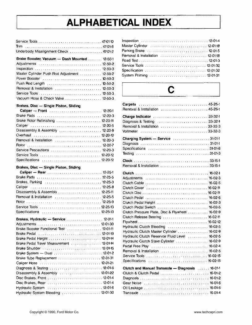
ALPHABETICAL INDEX
Service Tools 47-01-10 Trim 47-01-8 Underbody Misalignment Check 47-01-2
Brake Booster Vacuum - Dash Mounted 12-50-1 Adjustments 12-50-2 Inspection 12-50-3 Master Cylinder Push Rod Adjustment 12-50-2 Power Booster 12-50-3 Push Rod Length 12-50-2 Removal amp Installation 12-50-3 Service Tools 12-50-3 Vacuum Hose amp Check Valve 12-50-3
Brakes Disc - Single Piston Sliding Caliper - Front 12-20-1
Brake Pads 12-20-3 Brake Rotor Refinishing 12-20-11 Caliper 12-20-5 Disassembly amp Assembly 12-20-8 Overhaul 12-20-10 Removal amp Installation 12-20-3 Rotor 12-20-7 Service Precautions 12-20-3 Service Tools 12-20-12 Specifications 12-20-12
Brakes Disc - Single Piston Sliding Caliper - Rear 12-25-1
Brake Pads 12-25-5 Brakes Parking 12-25-3 Caliper 12-25-8 Disassembly amp Assembly 12-25-11 Removal amp Installation 12-25-5 Rotor 12-25-9
Service Tools 12-25-13 Specifications 12-25-13
Brakes Hydraulic - Service 12-01-1 Adjustments 12-01-30 Brake Booster Functional Test 12-01-11 Brake Pedal 12-01-19 Brake Pedal Height 12-01-14 Brake Pedal Travel Measurement 12-01-14 Brake Shudder 12-01-15 Brake System - Dual 12-01-2 Brake Tube Replacement 12-01-31 Caliper Hose 12-01-21 Diagnosis amp Testing 12-01-6 Disassembly amp Assembly 12-01-22 Disc Brakes Front 12-01-4 Disc Brakes Rear 12-01-4 Hydraulic System 12-01-6 Hydraulic System Bleeding 12-01-30
Inspection 12-01-4 Master Cylinder 12-01-18 Parking Brake 12-01-5 Removal amp Installation 12-01-18 Road Test 12-01-3 Service Tools 12-01-32 Specification 12-01-32 System Priming 12-01-31
c Carpets 45-26-1 Removal amp Installation 45-26-1
Charge Indicator 33-32-1 Diagnosis amp Testing 33-32-1 Removal amp Installation 33-32-3 Voltmeter 33-32-3
Charging System - Service 31-01-1 Diagnosis 31-01-1 Specifications 31-01-8 Testing 31-01-3
Clock 33-15-1 Removal amp Installation 33-15-1
Clutch 16-02-1 Adjustments 16-02-3 Clutch Cable 16-02-5 Clutch Cover 16-02-11 Clutch Disc 16-02-11 Clutch Pedal 16-02-6 Clutch Pedal Height 16-02-3 Clutch Pedal Switch 16-02-5 Clutch Pressure Plate Disc amp Flywheel 16-02-9 Clutch Release Bearing 16-02-11 Flywheel 16-02-12 Hydraulic Clutch Bleeding 16-02-5 Hydraulic Clutch Master Cylinder 16-02-9 Hydraulic Clutch Reservoir Fluid Level 16-02-5 Hydraulic Clutch Slave Cylinder 16-02-9 Pedal Free Play 16-02-4 Removal amp Installation 16-02-5 Service Tools 16-02-15 Specifications 16-02-15
Clutch and Manual Transaxle - Diagnosis 16-01-1 Clutch amp Clutch Pedal 16-01-2 Diagnosis 16-01-2 Gear Noise 16-01-6 Oil Leakage 16-01-6 Transaxle 16-01-4
Copyright copy 1990 Ford Motor Co wwwtechcapricom
ALPHABETICAL INDEX
Compressor amp Clutch 36-39-1 Clutch Pulley Bearing 36-39-7 DCompressor 36-39-2 Maintenance 36-39-1 Pressure Plate Pulley amp Field Coil 36-39-2 Door - Hinge Latch Manual Lock and
Refrigerant Oil Addition 36-39-1 Weatherstrip 44-06-1
Removal amp Installation 36-39-2 Adjustments 44middot06-2
Service Tools 36-39-8 Door Alignment 44middot06-2 Door Bumper 44-06-7
Console Floor 45middot31middot1 Door Bumper Guide 44-06middot8
Console Front 45middot31-2 Door Check Assembly 44middot06middot7
Console Rear 45-31-1 Door Inspection 44-06-2
Removal amp Installation 45-31-1 Door Latch 44middot06middot5
Shifter Boot 45-31-4 Door Latch Release Lever 44-06-5 Door Lock Cylinder 44-06middot6
Convertible 47-07-1 Door Striker 44-06-3
Adjustments 47-07-2 Front Door amp Hinges 44middot06-4
Convertible Top Assembly 47-07-3 Outside Door Handle 44-06middot6
Convertible Top Material 47-07-4 Removal amp Installation 44-06-4
Convertible Top Retainer 47-07-4 Specifications 44-06-9
Convertible Top-to-Windshield Adjustment 47-07-3 Weatherstrip 44-06middot8
Door Glass Fit 47-07-3 Door Lock Power 44-16-1 Latch Effort 47middot07-2 Diagnosis amp Testing 44-16-2 Maintenance 47-07-1 Door Lock Actuator 44-16-5 Moulding Storage Cover-to-Convertible Top 47-07-10 Door Lock Control Switch 44-16-6 Plastic Window Rear 47-07-2 Removal amp Installation 44-16-5 Removal amp Installation 47-07middot3 Specifications 44middot16middot6 Specifications 47-07-17 Storage Compartment Lock Set amp Actuator 47middot07-13 Drive Belts Accessory - Service 27-02middot1
Storage Cover 47-07-15 Adjustments 27middot02-1
Storage Cover Bumpers 47middot07middot15 AlternatorWater Pump Drive Belt Tension 27middot02-1
Storage Cover Hinge 47-07-17 Drive Belt Alternator 27middot02-3
Storage Cover Latch Cables 47-07-13 Drive Belt Power Steering amp AlC 27middot02-4
Storage Cover Pivot Caps 47middot07middot12 Power Steering amp AC Drive Belt Tension 27-02middot2
Storage Cover Strikers 47-07-14 Removal amp Installation 27-02middot3
Storage Cover Support 47middot07-16 Storage Cover Trim 47-07-15 Storage Top Latch 47middot07-13 E Weatherstrip Covertible Top-to-Windshield 47-07middot10 Weatherstrip Rear Seat-tomiddotStorage Cover 47-07-11 Engine Coolant Temperature Indicating System 33-25-1 Weatherstrip Storage Covermiddotto-Body 47-07-11 Diagnosis amp Testing 33-25-1 Weatherstrips Convertible Top Side 47-07-10 Removal amp Installation 33middot25-5 Window Rear 47-07-4 Temperature Sending Unit 33-25-5
Cooling System - Service 27-01-1 Engine 16L 21middot10-1 Coolant Condition Check 27-01-6 Camshaft 21middot10-14 Coolant Draining amp Replacement 27-01-7 Camshaft Seals 21-10-22
Cooling System Flush Procedure 27-01-7 Connecting Rod 21-10-39 Cooling System Pressure Test 27-01-5 Core Plugs 21-10-23 Diagnosis amp Testing 27-01middot2 Crankshaft 21-10-39 Pressure Cap Testing 27-01middot4 Crankshaft End Play 21-10middot40 Service Tools 27-01-8 Crankshaft Main Bearings amp Connecting Thermostat Testing 27-01middot6 Rod Bearings 21-10-16
Copyright copy 1990 Ford Motor Co wwwtechcapricom
ALPHABETICAL INDEX
Crankshaft Oil Clearance 21-10-40 Diagnosis amp Testing 27middot10middot2 Crankshaft Oil Seal Front 21-10-23 Removal amp Installation 27-10-9 Crankshaft Oil Seal Rear 21middot10-23 Specifications 27-10-10 Cylinder Block 21-10-34
Fuel Filters 24-51-1 Cylinder Block Flatness 21-10middot35
Inmiddot Line Filter 24-51-1 Cylinder Bores 21-10-36
In-Tank Filter 24-51middot1 Cylinder Head 21-10-42
RemOVAl amp Installation 24-51-1 Disassembly amp Assembly 21-10-24 Engine Mount Front 21middot10middot9 Fuel Injection Electronic 24-05-1 Engine Mount Rear 21middot10middot9 Adjustments 24-05-13 Engine Mounts RH 21-10-9 Airflow 24-05-8 Exhaust Manifold 21middot10-18 Air Induction System 24-05-6 HLA 21-10-46 BAC Valve 24-05-16 Intake Manifold 21-10-17 BP Sensor 24-05-16 Oil Pan 21-10middot19 Bypass Air Control Valve 24-05-9 Oil Pump 21-10-20 Diagnosis amp Testing 24-05-13 Piston amp Connecting Rod Assembly 21-10-21 Electronic Control Assembly 24-05-14 Pistons Piston Rings amp Piston Pins 21-10-37 Electronic Engine Control 24-05middot10 Removal amp Installation 21-10-2 Engine Coolant Temperature Sensor 24-05-15 Service Procedures 21-10-34 Fuel Injectors 24-05-15 Service Tools 21-10-49 Fuel System 24-05-4 Specifications 21-10-47 Idle Speed 24-05-13 Subassemblies 21middot10-32 Oxygen Sensor 24-05-16 Timing Belt 21-10-12 Removal amp Installation 24-05-13 Valve Stem Seals 21-10-19 Service Tools 24-05-17
Specifications 24-05-17Engine Gasoline - Service 21-01-1
Throttle Body 24-05-13 Camshaft Lobe Lift 21-01-4
Throttle Position Sensor 24-05-15 Compression Test 21-01-3
Turbo Boost Gauge 24middot05-16 Diagnosis amp Testing 21-01-2
Vane Air Flow Meter 24-05-14 Emissions Calibration Label 21-01-2 Engine Identification 21-01-2 Fuel Level Indicating System 33-20-1 Engine Oil Leaks 21middot01-2 Diagnosis amp Testing 33-20middot1 Exhaust Emission Control System 2101-2 Fuel Gauge 33-20-3 Positive Closed-Type Crankcase Ventilation Fuel Tank Sending Unit 33-20middot3
System 21-01-2 Removal amp Installation 33-20-3 Service Tools 21middot01-5
Fuel Pump - Electric 24-35-1 Valve Train Analysis 21-01-4
Control Circuit 24-35-2 Exhaust System 26-01-1 Fuel Pump Relay 24-35-4 Diagnosis 26-01-1 Pressure Regulator 24-35-3 Exhaust Leakage or Noise 26-01-1 Removal amp Installation 24-35-3 Removal amp Installation 26-01-4 Fuel System - Service 24-01-1 Restricted Exhaust System 26-01-3
F
Air Cleaner 24-01-2 Cleaning amp Inspection 24-01-2 Fuel Injection Electronic 24-01-2 Testing amp Adjustments 24-01-2
Fuel Tanks and Lines 24-50-1
Fan Electro-Drive Cooling 27-10-1 Fuel Filler Door 24-50-3
Coolant Temperature Switch 27-10middot9 Fuel Filler Neck 24-50-5
Cooling Fan 27-10middot9 Fuel System Pressure Relief 24-50-2
Cooling Fan Motor 27-10-9 Fuel Tank 24-50-4
Cooling Fan Relay 27-10-10 Removal amp Installation 24-50-2
Copyright copy 1990 Ford Motor Co wwwtechcapricom
ALPHABETICAL INDEX
Fuses amp Circuit Breakers 34-50-1 Fuse link 34-50-4 Fuse link Charging System 34-50-3
Fuse Panel Interior 34-50-3 Main Fuse Box 34-50-3 Removal amp Installation 34-50-3
G Glass Stationary - Windshield 43-02-1 Mouldings Front Window 43-02-1 Removal amp Installation 42-02-1 Windshield 43-02-4
H Halfshafts amp CV Joints - Front-Wheel Drive 15-22-1 Diagnosis 15-22-5 Disassembly amp Assembly 15-22-11 Halfshaft Handling 15-22-4 J oint shaft 15-22-11 Removal amp Installation 15-22-8 Rzeppa CV Joint 15-22-13 Service Tools 15-22-22 Specifications 15-22-22 Tripo Joint 15-22-19
Hardtop Removable 47-10-1 Exterior Mouldings Side amp Rear 47-10-4 Hardtop Front Attachment Bracket 47-10-5 Hardtop Side amp Rear Windows 47-10-6 Hardtop-to-Vehicle Weatherstrip 47-10-4 Headlining 47-10-6 Mouldings Roof 47-10-4 Removal amp Installations 47-10-1 SideRear Attachments 47-10-5 Side Window Opening Weatherstrip 47-10-4 Trim Panel Rear 47-10-3 Trim Panels Interior Side 47-10-3 Window Retainer Moulding Side 47-10-3 Wiring Harness 47-10-5
Headlamp System 32-02-1 Adjustments 32-02-15 Diagnosis amp Testing 32-02-6 Fog Lamp 32-02-18 Fog Lamp Switch 32-02middot18 Headlamp Aim 32middot02middot15 Headlamp Assembly 32middot02middot16 Headlamp Motor 32middot02middot16 Headlamp Motor Switch 32middot02middot18 Headlamp Switch 32middot02middot17 High BeamFlashmiddottomiddotPass Switch 32middot02middot18
High Beam Indicator Lamp Bulb 32-02middot18 Linkage 32middot02-17 Removal amp Installation 32-02middot15
Heater amp Power Ventilation System 36-10middot1 Adjustments 36-10-15 Air Distribution 36middot10-2 Air Door Control Cable 36-10-16 Airflow 36-10middot1 Air Inlet Duct 36middot10middot26 Blower Case Assembly 36-10-19 Blower Motor 36-10-18 Blower Motor Resistor 36-10-18 Blower Switch 36-10middot17 Control Cables 36middot10-17 Defroster Ducts 36-10middot24 Defroster Tubes amp Side Demister Tubes 36middot10middot25 Diagnosis amp Testing 36middot10middot5 Function Selector Cable 36middot10middot15 Function Selector Rod 36-10-15 Heat Ducts Rear Seat 36middot10-25 Heater Case 36middot10-20 Heater Control Panel 36-10-16 Heater Core 36-10-22 Heater Hoses 36-10-23 Heater Tube LH 36middot10-27 Instrument Panel Ducts 36middot10-26 Register LH Side amp Center 36middot10middot24 Register RH Side 36-10-24 Removal amp Installation 36-10-16 Temperature Control 36-10middot2 Temperature Control Cable 36-10-15
Heating System - Service 36-01-1 Bench Test 36-01-3 Diagnosis 36-01-4 Heater Core 36-01middot2 Heater Core Leak Test 36middot01middot3 Heating Systems amp Control Doors 36middot01middot2 Pressure Test 36middot01-3 Service Tools 36middot01middot5 Testing 36-01-2
HOisting Jacking amp Towing 10middot04middot1 Hoisting amp Jacking 10middot04middot1 TmiddotHooks Front 10middot04-5 TmiddotHooks Rear 10middot04middot5 Towing 10-04-3 Towing Procedures 10-04-4 Towing Slings 10middot04middot3
Hood Hinge amp latch 44-08-1 Adjustments 44-08-2 Hood 44-08middot8 Hood Alignment 44-08-2 Hood Bumpers 44-08middot3 Hood Hinge 44middot08-5 Hood Latch 44middot08middot5 Copyright copy 1990 Ford Motor Co wwwtechcapricom
ALPHABETICAL INDEX
Hood Release Cable 44-08-6 Instrument Panel amp Glove Compartment 45-61-1 Hood Safety Latch 44-08-6 Instrument Cluster Bezel 45-61-1 Hood Seals 44-08-5 Instrument Panel Assembly 45-61-2 Hood Support Rod 44-08-7 Removal amp Installation 45-61-1 Hood Weatherstrip 44-08-4 Latch Adjustments 44-08-2
Removal amp Installation 44-08-3
Horns 35-80-1 Adjustments 35-80-3 Lamps Interior 32-60-1 Diagnosis amp Testing 35-80-1 Diagnosis amp Testing 32-60-2 Horn Relay 35-80-4 Door Switch 32-60-7 Horn Switch 35-80-4 LampBlub Glove Compartment 32-60-8 Removal amp Installation 35-80-3 Lamp Dome 32-60-6
Lamps Courtesy 32-60-7
LensBulb Cargo Lamp 32-60-9 Removal amp Installation 32-60-6
Lamps - Parking Rear and Marker 32-20-1 Identification Codes 10-01-1 Combination LampBulb Replacement 32-20-7 Anti-Theft Labels 10-01-2 Combination Lamp Rear 32-20-6 Exteriorllnterior Labels 10-01-4 Diagnosis amp Testing 32-20-2 Label Locations 10-01-3 Hi-Mount Brakelamp 32-20-7 Official Vehicle Identification Number 10-01-1 License Plate LampBulb 32-20-7 Replacement VIN Label 10-01-2 Parking LampBulb Front 32-20-6 Vehicle Certification Label 10-01-2 Removal amp Installation 32-20-6
Side Marker LampBulb Front 32-20-6Ignition Switch 31-20-1
Side Marker Lamps Rear 32-20-8Ignition Lock Tumbler 31-20-2
Stop lamp Switch 32-20-8Non-Functioning Locks 31-20-3 Removal amp Installation 31-20-2 Lubrication Points and Lubricant Switch Blade-Type 31-20-1 Specifications 10-03-1 Testing 31-20-1 Lubrication 10-03-1
Specifications 10-03-3Ignition System Service 23-03-1 Diagnosis amp Testing 23-03-2 Luggage Compartment - Door Hinge Latch Disassembly amp Assembly 23-03-4 Lock and Weatherstrip 44-10-1 Distributor 23-03-4 Adjustments 44-10-1 Distributor Cap amp Rotor 23-03-2 Alignment 44-10-1 Ignition Coil 23-03-3 Door 44-10-3
Operation 23-03-2 Door Bumpers 44-10-8 Gas Lift Cylinders 44-10-6Removal amp Installation 23-03-2
Secondary Ignition Wires 23-03-2 Glove Compartment 44-10-9
Spark Plugs 23-03-3 Hinge 44-10-5 Latch 44-10-5
Instrument Cluster 33-01-1 Latch Glove Compartment 44-10-10 Diagnosis amp Testing 33-01-4 Lock Cylinder 44-10-5 Disassembly amp Assembly 33-01-12 Lock Glove Compartment 44-10-10 Heater Control Panel Bulb 33-01-11 Removal amp Installation 44-10-2 Instrument Cluster Bulbs 33-01-11 Spoiler 44-10middot8 Panel Dimmer SWitch 33-01-11 Striker 44-10-2 Removal amp Installation 33-01-10 Striker Glove Compartment 44-10-9 Speed Sensor 33-01-11 Weatherstrip 44-10-7
Copyright copy 1990 Ford Motor Co wwwtechcapricom
ALPHABETICAL INDEX
M Mirrors Exterior 42-25-1 Diagnosis amp Testing 42-25-2 Mirror Assembly 42-25-7 Removal amp Installation 42-25-7 Switch 42-25-7
Mirrors Inside 42-21-1 Removal amp Installation 42-21-1
Mouldings 45-16-1 Convertible Top Retainer 45-16-1 Door Scuff Plate amp Side Trim 45-16-4 Hardtop Header Trim Cover 45-16-3 Removal amp Installation 45-16-1 Specifications 45-16-4 Windshield Moulding Side 45-16-2 Windshield Moulding Upper 45-16-2
N Noise Vibration and Harshness 18-01-1 Diagnosis ampTesting 18-01-6 Diagnostic Theory 18-01-1 Glossary 18-01-2 Non-Transaxle Noise 18-01-4 NVH Diagnosis 18-01-4 Road Test 18-01-4 Service Tools 18-01-12 Transaxle Noise 18-01-4
o Oil Pressure Indicating Svstem 33-34-1 Diagnosis amp Testing 33-34-1 Oil Pressure Sending Unit 33-34-4 Removal amplnstallaon 33-34-4
p I Parking Brake Cable Actuated shy
Rear Wheels 12-70-1 Adjustment 12-70-2 Cable Parking Brake 12-70-2
Cables Long 12-70-4 Parking Brake Lever 12-70-3 Removal amp Installation 12-70-3
R Radiator 27-03-1 Cleaning External amp Internal 27-03-13 Leak Testing 27-03-13 Oil Cooler Transfer or Replacement 27-03-13 Radiator Core 27-03-14 Radiator Tank 27-03-5 Removal amp Installation 27-03-3 Service Procedures 27-03-14 Service Tools 27-03-17 Testing 27-03-13 Thermostat 27-03-5 Water Pump 27-03-4
Restraint Svstem - Supplemental Air Bag 41-58-1 Air Bag Clockspring 41-58-32 Air Bag Module 41-58-31 Backup Power Supply 41-58-32 Deactivating the System 41-58-29 Deployed Air Bag 41-58-28 Descriptions 41-58-1 Diagnosis ampTesting 41-58-4 Diagnostic Assembly 41-58-31 Disposal Procedures 41-58-27 Live Air Bags 41-58-27 Operation 41-58-4 Parts Replacement 41-58-26 Reactivating the System 41-58-29 Removal amp Installation 41-58-29 Sensor Front Center 41-58-29 Sensor Front Left or Right 41-58-30 Sensor Rear 41-58-30 Service Precautions 41-58-27 Specifications 41-58-32 Undeployed Air Bag Faulty 41-58-28
I s Scheduled Maintenance 10-02-1 Emission Control Information Decal 10-02-1 Maintenance Schedules 10-02-3
Seat and Shoulder Safetv Belts 41-50-1 Belt Webbing 41-50-5
Copyright copy 1990 Ford Motor Co wwwtechcapricom
ALPHABETICAL INDEX
Buckle Assembly Front 41-50-2 Cleaning 41-50-5 Major Service Operations 41-50-4 Removal amp Installation 41-50-2 Retractor amp Harness Assembly Front 41-50-2 Retractor amp Harness Assembly Rear 41-50-3 Safety Belt Maintenance 41-50-4 Seat Buckle Rear 41-50-4
Seat Child Restraint - Tether Attachment 41-52-1 Installation 41-52-1
Seats Front 41-04-1 Head Restraint amp Cover 41-04-7 Lumbar Support 41-04-8 Reclining Mechanisms 41-04-7 Removal amp Installation 41-04-1 Seat Back 41-04-4 Seat Back Cover amp Cushion 41-04-5 Seat Cover amp Cushion 41-04-3 Seat Height Adjuster LH Seat 41-04-9 Seat Height Adjustment Mechanism Control
Assembly LH Seat 41-04-9 Specifications 41-04-10
Seats Rear 41-20-1 Actuator Lock Set 41-20-8 Cable Actuator 41-20-7 Latch Seat Back 41-20-5 Latch Cable Seat Back 41-20-6 Removal amp Installation 41-20-1 Seat Back amp Cover 41-20-1 Seat Cushion 41-20-4
Shift Control Linkage 17-02-1 Adjustments 17-02-2 Disassembly amp Assembly 17-02-7 Gear Selector 17-02-7 Gear Selector Assembly 17-02-5 Removal amp Installation 17-02-4 Shift Control Cable 17-02-4 Specifications 17-02-10
Sound Systems 35-01-1 AMFM Multiplex Radio - ESR 35-01-3 AMFM Multiplex with Cassette Player 35-01-4 Cassette Tape Player 35-01-3 Diagnosis amp Testing 35-01-6 Premium Sound 35-01-2 Premium Sound Amplifier 35-01-18 Radio Reception 35-01-2 Removal amp Installation 35-01-17
Speakers 35-30-1 Diagnosis 35-30-1 Door Mounted Speakers 35-30-2
Rear Seat Speakers 35-30-3 Removal amp Installation 35-30-2
Speed Control System 37-01-1 Actuator 37-01-11 Actuator Cable 37-01-9 Adjustments 37-01-9 CableActuator Assembly 37-01-10 Clutch Pedal Height 37-01-9 Control Module 37-01-10 Control Switches 37-01-9 Diagnosis amp Testing 37-01-3 Removal amp Installation 37-01-9
Speedometer 33-10-1 Assembly 33-10-4 Diagnosis amp Testing 33-10-1 Removal amp Installation 33-10-3 Speedometer Cable Core 33-10-4 Speedometer Driven Gear 33-10-4
Starter Positive Engagement 28-02-1 Disassembly amp Assembly 28-02-5 Jump Starting 28-02-2 Pinion Depth Adjustment 28-02-3 Removal amp Installation 28-02-5 Service Tools 28-02-13 Specifications 28-02-13 Starter Motor No-Load Test 28-02-4 Testing 28-02-2
Starting System - Service 28-01-1 Diagnosis amp Testing 28-01-2 Neutral Safety Switch 28-01-7 On-Vehicle Inspection 28-01-2 Removal amp Installation 28-01-7 Service Tools 28-01-7 Voltage Drop Tests 28-01-3
Steering Column 13-04-1 Air Bag Module 13-04-2 Component Fasteners 13-04-2 Disassembly amp Assembly 13-04-6 Intermediate Shaft 13-04-4 Removal amp Installation 13-04-3 Specifications 13-04-10 Steering Column Support Brackets 13-04-5 Steering Wheel 13-04-3 Turn Signal Cancel Cam Service 13-04-9
Steering Gear Power Rack-and-Pinion 13-46-1 Adjustments 13-46-5 Disassembly amp Assembly 13-46-7 Dust Boot 13-46-6 Rack Yoke Preload 13-46-5 Removal amp Installation 13-46-6
Copyright copy 1990 Ford Motor Co wwwtechcapricom
ALPHABETICAL INDEX
Service Tools 13-46-17 Specifications 13-46-17 Tie Rod End 13-46-6
Steering Power - Hoses 13-55-1 High Pressure Hose 13-55-2 PressureReturn Tubing 13-55-3 Removal amp Installation 13-55-2 Return Hose 13-55-3
Steering Pump Power 13-51-1 Adjustments 13-51-2 Cleaning amp Inspection 13-51-6 Disassembly amp Assembly 13-51-4 Drive Belt Tension 13-51-2 Fluid Level Check 13-51-2 Flushing Power Steering System 13-51-6 Power Steering Pump 13-51-4 Pressure Regulator Valve 13-51-3 Pressure Switch 13-51-3 Pump Assembly 13-51-3 Removal amp Installation 13-51-3 Start-Up Procedure 13-51-2 Testing 13-51-2
Steering - Service 13-01-1 Pump Flow amp Pressure Tests 13-01-4 Service Tools 13-01-7 Specifications 13-01-7 Steering Wheel Free Play 13-01-5 Testing 13-01-2
Suspension Front 14-10-1 Ball Joint 14-10-2 Control Arm 14-10-5 Disassembly amp Assembly 14-10-5 Removal amp Installation 14-10-2 Se+vice Tools 14-10-6 Specifications 14-10-6 Strut amp Spring 14-10-3
Suspension Rear 14-32-1 Control Arms amp Trailing Arm 14-32-7 Removal amp Installation 14-32-4 Service Tools 14-32-11 Specifications 14-32-11 Spindle 14-32-6 Strut amp Spring Rear 14-32-4
Suspension - Service 14-01-1 Adjustments 14-01-6 Ball Joints 14-01-4 Camber 14-01-6 Control Arms amp Stabilizers 14-01-4 Diagnosis amp Testing 14-01-1
Heights 14-01-3 Specifications 14-01-9 Steering Wheel Centering 14-01-8 Steering Wheel Play 14-01-4 Struts 14-01-3 Tie Rods 14-01-4 Toe Rear 14-01-7 Toe In Front 14-01-6 Wheel Alignment 14-01-4
T Tachometer 33-11-1 Diagnosis amp Testing 33-11-1 Removal amp Installation 33-11-5
Throttle Linkage 24-60-1 Adjustments 24-60-1 Free Play 24-60-1 Removal amp Installation 24-60-2 Throttle Cable 24-60-2 Wide-Open Throttle Position 24-60-1
Transaxle Automatic - 4EAT 17-27-1 2-3 Accumulator 17-27-80 3-4 Accumulator 17-27-77 Adjustments 17-27-29 Bearing Housing 17-27-94 Bearing Locator 17middot27middot96 Bearing Preload amp Shim Selection 17middot27middot31 BearingStator Support 17-27-95 Cleaning amp Inspection 17-27-97 Clutch Assemblies 17middot27middot68 Diagnosis amp Testing 17-27middot4 Differential 17middot27middot90 Disassembly amp Assembly 17-27middot42 Idler Gear 17middot27-92 Kickdown Cable 17middot27middot29 Major Service Operations 17-27-29 Oil Cooler 17middot27-31 Oil Pump 17-27-63 One-Way Clutch amp Plantary Carrier Assembly 17-27-76 Output Gear 17-27middot91 Removal amp Installation 17-27-36 Service Tools 17middot27-102 Small Sun Gear amp One-Way Clutch 17-27-74 Specifications 17-27-100 Subassemblies 17-27-63 Torque Converter 17-27-98 Transaxle Fluid Level Check 17-27-29 Valve Body 17-27-80
Copyright copy 1990 Ford Motor Co wwwtechcapricom
ALPHABETICAL INDEX
Transaxle Automatic - Service 17-01-1 Description 17-01-1
Transaxle Manual- 5-Speed - Non-Turbo Engine 16-37-1
Cleaning amp Inspection 16-37-43 Clutch Housing 16-37-25 Differential 16-37-37 Disassembly amp Assembly 16-37-17 Gearshift Linkage 16-37-13 General Service Procedures 16-37-15
Input Shaft 16-37-43 Main Shaft 16-37-44 Main Shift Rail 16-37-40
Operation 16-37-2 Removal amp Installation 16-37-5 Service Tools 16-37-46 Shift Linkage 16-37-5 Specifications 16-37-46 Subassemblies 16-37-24 Transaxle Fluid Level Check 16-37-15 Transaxle Housing 16-37-30 Transaxle Oil Seal 16-37-10
Transaxle Manual - 5-Speed - Turbo Engine 16-38middot1 Differential 16-38-39 Differential Shim Selection 16-38-63 Disassembly amp Assembly 16middot38-18 Gear amp Shaft 16-38-35 Gearshift Linkage 16-38-7 Input Gear Shaft Shim Selection 16-38-61 Input Shaft Bearing 16-38-57 Main Shaft Shim Selection 16-38-58 Operation 16-38-3 Removal amp Installation 16-38-7 Service Procedures 16-38-17 Service Tools 16-38middot66 Shift Linkage 16middot38middot6 Specifications 16middot38-65 Subassemblies 16middot38middot35 Transaxle Fluid Level Check 16middot38middot17 Transaxle Oil Seal 16-38middot9
Trim Panels Interior 45middot03middot1 Convertible Top Storage Compartment 45middot03middot13 Cowl Side Trim Panel 45-03-8
Door Trim Panels 45middot03middot1
Floor Panels Luggage Compartment 45middot03-15 Luggage Compartment Rear Trim Panels 45-03-14 Luggage Compartment Side Trim Panels 45middot03-14
Rear Quarter Trim Panels 45middot03-8
Removal amp Installation 45middot03-1 Watershield 45-03-7
Turbo Boost Indicating System 33middot36middot01 Boost Gauge 33middot36middot3 Boost Gauge Sensor 33-36middot3 Diagnosis amp Testing 33-36middot1
Removal amp Installation 33middot36middot3
Turbocharger 24middot45middot1 Air-FuelExhaust Gas Flow 24-45-2 Bearing Clearance Check 24-45-9 Boost Control Automatic 24middot45-2 Coolant Return Hose 24middot45-7
Coolant Supply Hose amp Fitting 24-45-7 Diagnosis amp Testing 24middot45middot9 Intercooler 24middot45middot7 Intercooler Hoses 24middot45middot8 Lubrication 24middot45middot1 Oil Return Hose 24middot45middot7 Oil Supply Line 24middot45middot6 Operation 24middot45-2 Overboost Pressure Switch 24middot45-8 Removal amp Installation 24-45-2 Specifications 24-45-12
Turn Signal and Hazard Flasher 32middot40-1 Diagnosis amp Testing 32middot40middot2
Hazard Flasher Unit 32middot40-7 Removal amp Installation 32middot40middot6
SWitch Assembly 32middot40middot6 Turn Signal Flasher Unit 32middot40middot7
Wiper Switch amp Turn Signal High Beam Lever 32middot40middot6
w Warning Indicator 33-45middot1 Brake Indicator 33middot45-1 Diagnosis amp Testing 33middot45middot3 Engine Warning Lamp 33-45middot1 High Beam Indicator 33middot45middot2 Instrument Panel Lamps 33middot45middot1 Parking Brake Switch 33middot45middot10 Removal amp Installation 33middot45middot10
Safety Belt Indicator 33middot45middot1 Safety Belt Switch 33middot45middot11 Warningllndicator Lamp Bulbs 33middot45middot10
Wheel Hubs and Bearings - Front 11middot10-1 Bearing Front 11-10middot2 Brake RotorlWheel Hub 11-10-9
Diagnosis 11-10-2
Disassembly amp Assembly 11-10middot9 Removal amp Installation 11middot10middot3
Copyright copy 1990 Ford Motor Co wwwtechcapricom
ALPHABETICAL INDEX
Service Tools 11-10-15 Removal amp Installation 42-08-6
Specifications 11-10-15 Window Channel Rear 42-08-11
Steering KnuckleBearings 11-10-13 Window Channels 42-08-6
Wheel HubSteering Knuckle Assembly 11-10-3 Window Glass 42-08-7
Window Guide 42-08-7 Wheel Hubs amp Bearings - Rear 11-15-1
Window Stop 42-08-6 Adjustments 11-15-6
Bearing Preload 11-15-6 Windshield Washers 35-70-1
Bearing Races 11-15-9 Diagnosis amp Testing 35-70-2
Brake RotorBearing Hub Assembly 11-15-7 Nozzles amp Hose 35-70-4
Grease SealBearings 11-15-8 Pump 35-70-4
Inspection 11-15-2 Removal amp Installation 35-70-4
Removal amp Installation 11-15-7 Reservoir amp Washer Pump 35-70-4
Specifications 11-15-9 Washer Switch 35-70-5
Wheels and Tires - Service 11-01-1 Windshield Wipers 35-60-1
Diagnosis 11-01-5 Adjustments 35-60-8
Maintenance 11-01-2 Diagnosis amp Testing 35-60-3
Road Test 11-01-6 Linkage 35-60-10
Service 11-01-10 Removal amp Installation 35-60-8
Service Tools 11-01-14 Specifications 35-60-10
Specifications 11-01-13 Windshield Wiper Arm Position 35-60-8
Tire and Wheel Balance 11-01-11 Wiper Arm 35-60-9
Tire Inflation 11-01-3 Wiper Blade 35-60-8
Tire Lead 11-01-9 Wiper Motor 35-60-9
Vibration amp Roughness 11-01-6 Wiper Switch amp Lever 35-60-10
Wheel Lug Nuts 11-01-2 Wiring Harness - Connectors 34-01-1
WheelTire Runout 11-01-9 Connectors 34-01-1
Window Glass amp Mechanisms - Service 42-01-1 Removal amp Installation 34-01-1
Lubrication 42-01-1 Wire Ends 34-01-2
Wiring Harnesses 34-26-1Window Rear - Defroster 36-86-1 Dash Panel 34-26-5Bus Bar Terminal Repair 36-86-7 Door 34-26-6Diagnosis amp Testing 36-86-2 Engine Compartment 34-26-3Major Service Operations 36-86-6 Floor 34-26-7ONOFF Switch 36-86-7 Ground Cable 34-26-2Removal amp Installation 36-86-7 Hardtop 34-26-6
Windows Power 42-08-1 Instrument Panel 34-26-6
Adjustments 42-08-6 Lamps Rear 34-26-9 Diagnosis amp Testing 42-08-2 Luggage Compartment Lid 34-26-9 Door Quarter Window 42-08-11 Quarter Panel 34-26-8 Door Window Switch 42-08-6 Removal amp Installation 34-26-1 Motor Regulator Assembly 42-08-9 Starter amp Alternator Cables 34-26-3
Copyright copy 1990 Ford Motor Co wwwtechcapricom
Copyright copy 1990 Ford Motor Co wwwtechcapricom
We Want To Hear FroID youl------ Do you have any suggestions for improving this publication
FOR EXAMPLE
bull Did you find any errors
If yes Manual ________________Volume_____Page___
bull Were any subjects not covered
If yes Please describe _________________________
bull Were any sections confusing or hard to understand
If yes Manual ________________Volume_____ Page___
Please comment
bull Could you quickly find what you need Yes _________ No
Suggestions
bull Tell us who you are
Name _______________________________________________________________
Address ________________________________________
Position _____________________________ Company ______________________
It is most helpful if you would enclose a copy of each page marked with your suggestions
Copyright copy 1990 Ford Motor Co wwwtechcapricom
------------------------------------------------------------------------
DO NOT STAPLE - USE TRANSPARENT TAPE
NO POSTAGE NECESSARY IF MAILED
IN THE UNITED STATES
111111
BUSINESS REPLY MAIL FIRST CLASS PERMIT NO 400 DEARBORN MICH
POSTAGE WILL BE PAID BY ADDRESSEE
Ford Parts and Service Division Advanced Service Engineering Fairlane Technical Center PO Box 1902 Dearborn Michigan 48121
Copyright copy 1990 Ford Motor Co wwwtechcapricom
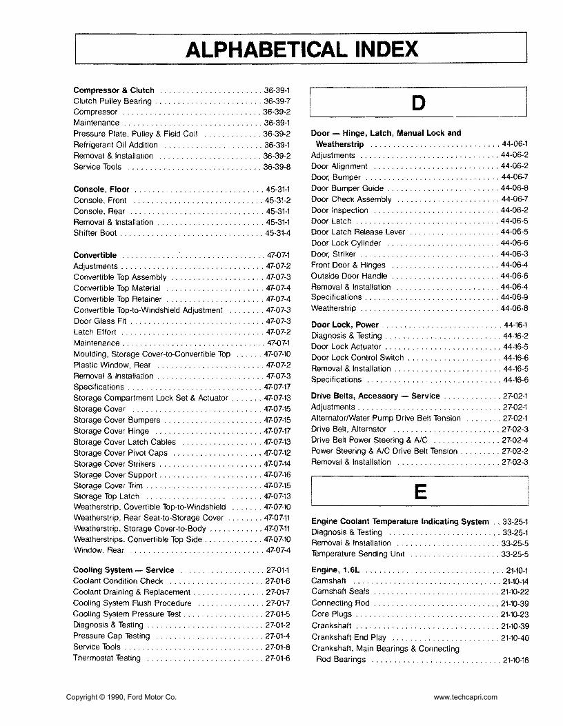
ALPHABETICAL INDEX
Compressor amp Clutch 36-39-1 Clutch Pulley Bearing 36-39-7 DCompressor 36-39-2 Maintenance 36-39-1 Pressure Plate Pulley amp Field Coil 36-39-2 Door - Hinge Latch Manual Lock and
Refrigerant Oil Addition 36-39-1 Weatherstrip 44-06-1
Removal amp Installation 36-39-2 Adjustments 44middot06-2
Service Tools 36-39-8 Door Alignment 44middot06-2 Door Bumper 44-06-7
Console Floor 45middot31middot1 Door Bumper Guide 44-06middot8
Console Front 45middot31-2 Door Check Assembly 44middot06middot7
Console Rear 45-31-1 Door Inspection 44-06-2
Removal amp Installation 45-31-1 Door Latch 44middot06middot5
Shifter Boot 45-31-4 Door Latch Release Lever 44-06-5 Door Lock Cylinder 44-06middot6
Convertible 47-07-1 Door Striker 44-06-3
Adjustments 47-07-2 Front Door amp Hinges 44middot06-4
Convertible Top Assembly 47-07-3 Outside Door Handle 44-06middot6
Convertible Top Material 47-07-4 Removal amp Installation 44-06-4
Convertible Top Retainer 47-07-4 Specifications 44-06-9
Convertible Top-to-Windshield Adjustment 47-07-3 Weatherstrip 44-06middot8
Door Glass Fit 47-07-3 Door Lock Power 44-16-1 Latch Effort 47middot07-2 Diagnosis amp Testing 44-16-2 Maintenance 47-07-1 Door Lock Actuator 44-16-5 Moulding Storage Cover-to-Convertible Top 47-07-10 Door Lock Control Switch 44-16-6 Plastic Window Rear 47-07-2 Removal amp Installation 44-16-5 Removal amp Installation 47-07middot3 Specifications 44middot16middot6 Specifications 47-07-17 Storage Compartment Lock Set amp Actuator 47middot07-13 Drive Belts Accessory - Service 27-02middot1
Storage Cover 47-07-15 Adjustments 27middot02-1
Storage Cover Bumpers 47middot07middot15 AlternatorWater Pump Drive Belt Tension 27middot02-1
Storage Cover Hinge 47-07-17 Drive Belt Alternator 27middot02-3
Storage Cover Latch Cables 47-07-13 Drive Belt Power Steering amp AlC 27middot02-4
Storage Cover Pivot Caps 47middot07middot12 Power Steering amp AC Drive Belt Tension 27-02middot2
Storage Cover Strikers 47-07-14 Removal amp Installation 27-02middot3
Storage Cover Support 47middot07-16 Storage Cover Trim 47-07-15 Storage Top Latch 47middot07-13 E Weatherstrip Covertible Top-to-Windshield 47-07middot10 Weatherstrip Rear Seat-tomiddotStorage Cover 47-07-11 Engine Coolant Temperature Indicating System 33-25-1 Weatherstrip Storage Covermiddotto-Body 47-07-11 Diagnosis amp Testing 33-25-1 Weatherstrips Convertible Top Side 47-07-10 Removal amp Installation 33middot25-5 Window Rear 47-07-4 Temperature Sending Unit 33-25-5
Cooling System - Service 27-01-1 Engine 16L 21middot10-1 Coolant Condition Check 27-01-6 Camshaft 21middot10-14 Coolant Draining amp Replacement 27-01-7 Camshaft Seals 21-10-22
Cooling System Flush Procedure 27-01-7 Connecting Rod 21-10-39 Cooling System Pressure Test 27-01-5 Core Plugs 21-10-23 Diagnosis amp Testing 27-01middot2 Crankshaft 21-10-39 Pressure Cap Testing 27-01middot4 Crankshaft End Play 21-10middot40 Service Tools 27-01-8 Crankshaft Main Bearings amp Connecting Thermostat Testing 27-01middot6 Rod Bearings 21-10-16
Copyright copy 1990 Ford Motor Co wwwtechcapricom
ALPHABETICAL INDEX
Crankshaft Oil Clearance 21-10-40 Diagnosis amp Testing 27middot10middot2 Crankshaft Oil Seal Front 21-10-23 Removal amp Installation 27-10-9 Crankshaft Oil Seal Rear 21middot10-23 Specifications 27-10-10 Cylinder Block 21-10-34
Fuel Filters 24-51-1 Cylinder Block Flatness 21-10middot35
Inmiddot Line Filter 24-51-1 Cylinder Bores 21-10-36
In-Tank Filter 24-51middot1 Cylinder Head 21-10-42
RemOVAl amp Installation 24-51-1 Disassembly amp Assembly 21-10-24 Engine Mount Front 21middot10middot9 Fuel Injection Electronic 24-05-1 Engine Mount Rear 21middot10middot9 Adjustments 24-05-13 Engine Mounts RH 21-10-9 Airflow 24-05-8 Exhaust Manifold 21middot10-18 Air Induction System 24-05-6 HLA 21-10-46 BAC Valve 24-05-16 Intake Manifold 21-10-17 BP Sensor 24-05-16 Oil Pan 21-10middot19 Bypass Air Control Valve 24-05-9 Oil Pump 21-10-20 Diagnosis amp Testing 24-05-13 Piston amp Connecting Rod Assembly 21-10-21 Electronic Control Assembly 24-05-14 Pistons Piston Rings amp Piston Pins 21-10-37 Electronic Engine Control 24-05middot10 Removal amp Installation 21-10-2 Engine Coolant Temperature Sensor 24-05-15 Service Procedures 21-10-34 Fuel Injectors 24-05-15 Service Tools 21-10-49 Fuel System 24-05-4 Specifications 21-10-47 Idle Speed 24-05-13 Subassemblies 21middot10-32 Oxygen Sensor 24-05-16 Timing Belt 21-10-12 Removal amp Installation 24-05-13 Valve Stem Seals 21-10-19 Service Tools 24-05-17
Specifications 24-05-17Engine Gasoline - Service 21-01-1
Throttle Body 24-05-13 Camshaft Lobe Lift 21-01-4
Throttle Position Sensor 24-05-15 Compression Test 21-01-3
Turbo Boost Gauge 24middot05-16 Diagnosis amp Testing 21-01-2
Vane Air Flow Meter 24-05-14 Emissions Calibration Label 21-01-2 Engine Identification 21-01-2 Fuel Level Indicating System 33-20-1 Engine Oil Leaks 21middot01-2 Diagnosis amp Testing 33-20middot1 Exhaust Emission Control System 2101-2 Fuel Gauge 33-20-3 Positive Closed-Type Crankcase Ventilation Fuel Tank Sending Unit 33-20middot3
System 21-01-2 Removal amp Installation 33-20-3 Service Tools 21middot01-5
Fuel Pump - Electric 24-35-1 Valve Train Analysis 21-01-4
Control Circuit 24-35-2 Exhaust System 26-01-1 Fuel Pump Relay 24-35-4 Diagnosis 26-01-1 Pressure Regulator 24-35-3 Exhaust Leakage or Noise 26-01-1 Removal amp Installation 24-35-3 Removal amp Installation 26-01-4 Fuel System - Service 24-01-1 Restricted Exhaust System 26-01-3
F
Air Cleaner 24-01-2 Cleaning amp Inspection 24-01-2 Fuel Injection Electronic 24-01-2 Testing amp Adjustments 24-01-2
Fuel Tanks and Lines 24-50-1
Fan Electro-Drive Cooling 27-10-1 Fuel Filler Door 24-50-3
Coolant Temperature Switch 27-10middot9 Fuel Filler Neck 24-50-5
Cooling Fan 27-10middot9 Fuel System Pressure Relief 24-50-2
Cooling Fan Motor 27-10-9 Fuel Tank 24-50-4
Cooling Fan Relay 27-10-10 Removal amp Installation 24-50-2
Copyright copy 1990 Ford Motor Co wwwtechcapricom
ALPHABETICAL INDEX
Fuses amp Circuit Breakers 34-50-1 Fuse link 34-50-4 Fuse link Charging System 34-50-3
Fuse Panel Interior 34-50-3 Main Fuse Box 34-50-3 Removal amp Installation 34-50-3
G Glass Stationary - Windshield 43-02-1 Mouldings Front Window 43-02-1 Removal amp Installation 42-02-1 Windshield 43-02-4
H Halfshafts amp CV Joints - Front-Wheel Drive 15-22-1 Diagnosis 15-22-5 Disassembly amp Assembly 15-22-11 Halfshaft Handling 15-22-4 J oint shaft 15-22-11 Removal amp Installation 15-22-8 Rzeppa CV Joint 15-22-13 Service Tools 15-22-22 Specifications 15-22-22 Tripo Joint 15-22-19
Hardtop Removable 47-10-1 Exterior Mouldings Side amp Rear 47-10-4 Hardtop Front Attachment Bracket 47-10-5 Hardtop Side amp Rear Windows 47-10-6 Hardtop-to-Vehicle Weatherstrip 47-10-4 Headlining 47-10-6 Mouldings Roof 47-10-4 Removal amp Installations 47-10-1 SideRear Attachments 47-10-5 Side Window Opening Weatherstrip 47-10-4 Trim Panel Rear 47-10-3 Trim Panels Interior Side 47-10-3 Window Retainer Moulding Side 47-10-3 Wiring Harness 47-10-5
Headlamp System 32-02-1 Adjustments 32-02-15 Diagnosis amp Testing 32-02-6 Fog Lamp 32-02-18 Fog Lamp Switch 32-02middot18 Headlamp Aim 32middot02middot15 Headlamp Assembly 32middot02middot16 Headlamp Motor 32middot02middot16 Headlamp Motor Switch 32middot02middot18 Headlamp Switch 32middot02middot17 High BeamFlashmiddottomiddotPass Switch 32middot02middot18
High Beam Indicator Lamp Bulb 32-02middot18 Linkage 32middot02-17 Removal amp Installation 32-02middot15
Heater amp Power Ventilation System 36-10middot1 Adjustments 36-10-15 Air Distribution 36middot10-2 Air Door Control Cable 36-10-16 Airflow 36-10middot1 Air Inlet Duct 36middot10middot26 Blower Case Assembly 36-10-19 Blower Motor 36-10-18 Blower Motor Resistor 36-10-18 Blower Switch 36-10middot17 Control Cables 36middot10-17 Defroster Ducts 36-10middot24 Defroster Tubes amp Side Demister Tubes 36middot10middot25 Diagnosis amp Testing 36middot10middot5 Function Selector Cable 36middot10middot15 Function Selector Rod 36-10-15 Heat Ducts Rear Seat 36middot10-25 Heater Case 36middot10-20 Heater Control Panel 36-10-16 Heater Core 36-10-22 Heater Hoses 36-10-23 Heater Tube LH 36middot10-27 Instrument Panel Ducts 36middot10-26 Register LH Side amp Center 36middot10middot24 Register RH Side 36-10-24 Removal amp Installation 36-10-16 Temperature Control 36-10middot2 Temperature Control Cable 36-10-15
Heating System - Service 36-01-1 Bench Test 36-01-3 Diagnosis 36-01-4 Heater Core 36-01middot2 Heater Core Leak Test 36middot01middot3 Heating Systems amp Control Doors 36middot01middot2 Pressure Test 36middot01-3 Service Tools 36middot01middot5 Testing 36-01-2
HOisting Jacking amp Towing 10middot04middot1 Hoisting amp Jacking 10middot04middot1 TmiddotHooks Front 10middot04-5 TmiddotHooks Rear 10middot04middot5 Towing 10-04-3 Towing Procedures 10-04-4 Towing Slings 10middot04middot3
Hood Hinge amp latch 44-08-1 Adjustments 44-08-2 Hood 44-08middot8 Hood Alignment 44-08-2 Hood Bumpers 44-08middot3 Hood Hinge 44middot08-5 Hood Latch 44middot08middot5 Copyright copy 1990 Ford Motor Co wwwtechcapricom
ALPHABETICAL INDEX
Hood Release Cable 44-08-6 Instrument Panel amp Glove Compartment 45-61-1 Hood Safety Latch 44-08-6 Instrument Cluster Bezel 45-61-1 Hood Seals 44-08-5 Instrument Panel Assembly 45-61-2 Hood Support Rod 44-08-7 Removal amp Installation 45-61-1 Hood Weatherstrip 44-08-4 Latch Adjustments 44-08-2
Removal amp Installation 44-08-3
Horns 35-80-1 Adjustments 35-80-3 Lamps Interior 32-60-1 Diagnosis amp Testing 35-80-1 Diagnosis amp Testing 32-60-2 Horn Relay 35-80-4 Door Switch 32-60-7 Horn Switch 35-80-4 LampBlub Glove Compartment 32-60-8 Removal amp Installation 35-80-3 Lamp Dome 32-60-6
Lamps Courtesy 32-60-7
LensBulb Cargo Lamp 32-60-9 Removal amp Installation 32-60-6
Lamps - Parking Rear and Marker 32-20-1 Identification Codes 10-01-1 Combination LampBulb Replacement 32-20-7 Anti-Theft Labels 10-01-2 Combination Lamp Rear 32-20-6 Exteriorllnterior Labels 10-01-4 Diagnosis amp Testing 32-20-2 Label Locations 10-01-3 Hi-Mount Brakelamp 32-20-7 Official Vehicle Identification Number 10-01-1 License Plate LampBulb 32-20-7 Replacement VIN Label 10-01-2 Parking LampBulb Front 32-20-6 Vehicle Certification Label 10-01-2 Removal amp Installation 32-20-6
Side Marker LampBulb Front 32-20-6Ignition Switch 31-20-1
Side Marker Lamps Rear 32-20-8Ignition Lock Tumbler 31-20-2
Stop lamp Switch 32-20-8Non-Functioning Locks 31-20-3 Removal amp Installation 31-20-2 Lubrication Points and Lubricant Switch Blade-Type 31-20-1 Specifications 10-03-1 Testing 31-20-1 Lubrication 10-03-1
Specifications 10-03-3Ignition System Service 23-03-1 Diagnosis amp Testing 23-03-2 Luggage Compartment - Door Hinge Latch Disassembly amp Assembly 23-03-4 Lock and Weatherstrip 44-10-1 Distributor 23-03-4 Adjustments 44-10-1 Distributor Cap amp Rotor 23-03-2 Alignment 44-10-1 Ignition Coil 23-03-3 Door 44-10-3
Operation 23-03-2 Door Bumpers 44-10-8 Gas Lift Cylinders 44-10-6Removal amp Installation 23-03-2
Secondary Ignition Wires 23-03-2 Glove Compartment 44-10-9
Spark Plugs 23-03-3 Hinge 44-10-5 Latch 44-10-5
Instrument Cluster 33-01-1 Latch Glove Compartment 44-10-10 Diagnosis amp Testing 33-01-4 Lock Cylinder 44-10-5 Disassembly amp Assembly 33-01-12 Lock Glove Compartment 44-10-10 Heater Control Panel Bulb 33-01-11 Removal amp Installation 44-10-2 Instrument Cluster Bulbs 33-01-11 Spoiler 44-10middot8 Panel Dimmer SWitch 33-01-11 Striker 44-10-2 Removal amp Installation 33-01-10 Striker Glove Compartment 44-10-9 Speed Sensor 33-01-11 Weatherstrip 44-10-7
Copyright copy 1990 Ford Motor Co wwwtechcapricom
ALPHABETICAL INDEX
M Mirrors Exterior 42-25-1 Diagnosis amp Testing 42-25-2 Mirror Assembly 42-25-7 Removal amp Installation 42-25-7 Switch 42-25-7
Mirrors Inside 42-21-1 Removal amp Installation 42-21-1
Mouldings 45-16-1 Convertible Top Retainer 45-16-1 Door Scuff Plate amp Side Trim 45-16-4 Hardtop Header Trim Cover 45-16-3 Removal amp Installation 45-16-1 Specifications 45-16-4 Windshield Moulding Side 45-16-2 Windshield Moulding Upper 45-16-2
N Noise Vibration and Harshness 18-01-1 Diagnosis ampTesting 18-01-6 Diagnostic Theory 18-01-1 Glossary 18-01-2 Non-Transaxle Noise 18-01-4 NVH Diagnosis 18-01-4 Road Test 18-01-4 Service Tools 18-01-12 Transaxle Noise 18-01-4
o Oil Pressure Indicating Svstem 33-34-1 Diagnosis amp Testing 33-34-1 Oil Pressure Sending Unit 33-34-4 Removal amplnstallaon 33-34-4
p I Parking Brake Cable Actuated shy
Rear Wheels 12-70-1 Adjustment 12-70-2 Cable Parking Brake 12-70-2
Cables Long 12-70-4 Parking Brake Lever 12-70-3 Removal amp Installation 12-70-3
R Radiator 27-03-1 Cleaning External amp Internal 27-03-13 Leak Testing 27-03-13 Oil Cooler Transfer or Replacement 27-03-13 Radiator Core 27-03-14 Radiator Tank 27-03-5 Removal amp Installation 27-03-3 Service Procedures 27-03-14 Service Tools 27-03-17 Testing 27-03-13 Thermostat 27-03-5 Water Pump 27-03-4
Restraint Svstem - Supplemental Air Bag 41-58-1 Air Bag Clockspring 41-58-32 Air Bag Module 41-58-31 Backup Power Supply 41-58-32 Deactivating the System 41-58-29 Deployed Air Bag 41-58-28 Descriptions 41-58-1 Diagnosis ampTesting 41-58-4 Diagnostic Assembly 41-58-31 Disposal Procedures 41-58-27 Live Air Bags 41-58-27 Operation 41-58-4 Parts Replacement 41-58-26 Reactivating the System 41-58-29 Removal amp Installation 41-58-29 Sensor Front Center 41-58-29 Sensor Front Left or Right 41-58-30 Sensor Rear 41-58-30 Service Precautions 41-58-27 Specifications 41-58-32 Undeployed Air Bag Faulty 41-58-28
I s Scheduled Maintenance 10-02-1 Emission Control Information Decal 10-02-1 Maintenance Schedules 10-02-3
Seat and Shoulder Safetv Belts 41-50-1 Belt Webbing 41-50-5
Copyright copy 1990 Ford Motor Co wwwtechcapricom
ALPHABETICAL INDEX
Buckle Assembly Front 41-50-2 Cleaning 41-50-5 Major Service Operations 41-50-4 Removal amp Installation 41-50-2 Retractor amp Harness Assembly Front 41-50-2 Retractor amp Harness Assembly Rear 41-50-3 Safety Belt Maintenance 41-50-4 Seat Buckle Rear 41-50-4
Seat Child Restraint - Tether Attachment 41-52-1 Installation 41-52-1
Seats Front 41-04-1 Head Restraint amp Cover 41-04-7 Lumbar Support 41-04-8 Reclining Mechanisms 41-04-7 Removal amp Installation 41-04-1 Seat Back 41-04-4 Seat Back Cover amp Cushion 41-04-5 Seat Cover amp Cushion 41-04-3 Seat Height Adjuster LH Seat 41-04-9 Seat Height Adjustment Mechanism Control
Assembly LH Seat 41-04-9 Specifications 41-04-10
Seats Rear 41-20-1 Actuator Lock Set 41-20-8 Cable Actuator 41-20-7 Latch Seat Back 41-20-5 Latch Cable Seat Back 41-20-6 Removal amp Installation 41-20-1 Seat Back amp Cover 41-20-1 Seat Cushion 41-20-4
Shift Control Linkage 17-02-1 Adjustments 17-02-2 Disassembly amp Assembly 17-02-7 Gear Selector 17-02-7 Gear Selector Assembly 17-02-5 Removal amp Installation 17-02-4 Shift Control Cable 17-02-4 Specifications 17-02-10
Sound Systems 35-01-1 AMFM Multiplex Radio - ESR 35-01-3 AMFM Multiplex with Cassette Player 35-01-4 Cassette Tape Player 35-01-3 Diagnosis amp Testing 35-01-6 Premium Sound 35-01-2 Premium Sound Amplifier 35-01-18 Radio Reception 35-01-2 Removal amp Installation 35-01-17
Speakers 35-30-1 Diagnosis 35-30-1 Door Mounted Speakers 35-30-2
Rear Seat Speakers 35-30-3 Removal amp Installation 35-30-2
Speed Control System 37-01-1 Actuator 37-01-11 Actuator Cable 37-01-9 Adjustments 37-01-9 CableActuator Assembly 37-01-10 Clutch Pedal Height 37-01-9 Control Module 37-01-10 Control Switches 37-01-9 Diagnosis amp Testing 37-01-3 Removal amp Installation 37-01-9
Speedometer 33-10-1 Assembly 33-10-4 Diagnosis amp Testing 33-10-1 Removal amp Installation 33-10-3 Speedometer Cable Core 33-10-4 Speedometer Driven Gear 33-10-4
Starter Positive Engagement 28-02-1 Disassembly amp Assembly 28-02-5 Jump Starting 28-02-2 Pinion Depth Adjustment 28-02-3 Removal amp Installation 28-02-5 Service Tools 28-02-13 Specifications 28-02-13 Starter Motor No-Load Test 28-02-4 Testing 28-02-2
Starting System - Service 28-01-1 Diagnosis amp Testing 28-01-2 Neutral Safety Switch 28-01-7 On-Vehicle Inspection 28-01-2 Removal amp Installation 28-01-7 Service Tools 28-01-7 Voltage Drop Tests 28-01-3
Steering Column 13-04-1 Air Bag Module 13-04-2 Component Fasteners 13-04-2 Disassembly amp Assembly 13-04-6 Intermediate Shaft 13-04-4 Removal amp Installation 13-04-3 Specifications 13-04-10 Steering Column Support Brackets 13-04-5 Steering Wheel 13-04-3 Turn Signal Cancel Cam Service 13-04-9
Steering Gear Power Rack-and-Pinion 13-46-1 Adjustments 13-46-5 Disassembly amp Assembly 13-46-7 Dust Boot 13-46-6 Rack Yoke Preload 13-46-5 Removal amp Installation 13-46-6
Copyright copy 1990 Ford Motor Co wwwtechcapricom
ALPHABETICAL INDEX
Service Tools 13-46-17 Specifications 13-46-17 Tie Rod End 13-46-6
Steering Power - Hoses 13-55-1 High Pressure Hose 13-55-2 PressureReturn Tubing 13-55-3 Removal amp Installation 13-55-2 Return Hose 13-55-3
Steering Pump Power 13-51-1 Adjustments 13-51-2 Cleaning amp Inspection 13-51-6 Disassembly amp Assembly 13-51-4 Drive Belt Tension 13-51-2 Fluid Level Check 13-51-2 Flushing Power Steering System 13-51-6 Power Steering Pump 13-51-4 Pressure Regulator Valve 13-51-3 Pressure Switch 13-51-3 Pump Assembly 13-51-3 Removal amp Installation 13-51-3 Start-Up Procedure 13-51-2 Testing 13-51-2
Steering - Service 13-01-1 Pump Flow amp Pressure Tests 13-01-4 Service Tools 13-01-7 Specifications 13-01-7 Steering Wheel Free Play 13-01-5 Testing 13-01-2
Suspension Front 14-10-1 Ball Joint 14-10-2 Control Arm 14-10-5 Disassembly amp Assembly 14-10-5 Removal amp Installation 14-10-2 Se+vice Tools 14-10-6 Specifications 14-10-6 Strut amp Spring 14-10-3
Suspension Rear 14-32-1 Control Arms amp Trailing Arm 14-32-7 Removal amp Installation 14-32-4 Service Tools 14-32-11 Specifications 14-32-11 Spindle 14-32-6 Strut amp Spring Rear 14-32-4
Suspension - Service 14-01-1 Adjustments 14-01-6 Ball Joints 14-01-4 Camber 14-01-6 Control Arms amp Stabilizers 14-01-4 Diagnosis amp Testing 14-01-1
Heights 14-01-3 Specifications 14-01-9 Steering Wheel Centering 14-01-8 Steering Wheel Play 14-01-4 Struts 14-01-3 Tie Rods 14-01-4 Toe Rear 14-01-7 Toe In Front 14-01-6 Wheel Alignment 14-01-4
T Tachometer 33-11-1 Diagnosis amp Testing 33-11-1 Removal amp Installation 33-11-5
Throttle Linkage 24-60-1 Adjustments 24-60-1 Free Play 24-60-1 Removal amp Installation 24-60-2 Throttle Cable 24-60-2 Wide-Open Throttle Position 24-60-1
Transaxle Automatic - 4EAT 17-27-1 2-3 Accumulator 17-27-80 3-4 Accumulator 17-27-77 Adjustments 17-27-29 Bearing Housing 17-27-94 Bearing Locator 17middot27middot96 Bearing Preload amp Shim Selection 17middot27middot31 BearingStator Support 17-27-95 Cleaning amp Inspection 17-27-97 Clutch Assemblies 17middot27middot68 Diagnosis amp Testing 17-27middot4 Differential 17middot27middot90 Disassembly amp Assembly 17-27middot42 Idler Gear 17middot27-92 Kickdown Cable 17middot27middot29 Major Service Operations 17-27-29 Oil Cooler 17middot27-31 Oil Pump 17-27-63 One-Way Clutch amp Plantary Carrier Assembly 17-27-76 Output Gear 17-27middot91 Removal amp Installation 17-27-36 Service Tools 17middot27-102 Small Sun Gear amp One-Way Clutch 17-27-74 Specifications 17-27-100 Subassemblies 17-27-63 Torque Converter 17-27-98 Transaxle Fluid Level Check 17-27-29 Valve Body 17-27-80
Copyright copy 1990 Ford Motor Co wwwtechcapricom
ALPHABETICAL INDEX
Transaxle Automatic - Service 17-01-1 Description 17-01-1
Transaxle Manual- 5-Speed - Non-Turbo Engine 16-37-1
Cleaning amp Inspection 16-37-43 Clutch Housing 16-37-25 Differential 16-37-37 Disassembly amp Assembly 16-37-17 Gearshift Linkage 16-37-13 General Service Procedures 16-37-15
Input Shaft 16-37-43 Main Shaft 16-37-44 Main Shift Rail 16-37-40
Operation 16-37-2 Removal amp Installation 16-37-5 Service Tools 16-37-46 Shift Linkage 16-37-5 Specifications 16-37-46 Subassemblies 16-37-24 Transaxle Fluid Level Check 16-37-15 Transaxle Housing 16-37-30 Transaxle Oil Seal 16-37-10
Transaxle Manual - 5-Speed - Turbo Engine 16-38middot1 Differential 16-38-39 Differential Shim Selection 16-38-63 Disassembly amp Assembly 16middot38-18 Gear amp Shaft 16-38-35 Gearshift Linkage 16-38-7 Input Gear Shaft Shim Selection 16-38-61 Input Shaft Bearing 16-38-57 Main Shaft Shim Selection 16-38-58 Operation 16-38-3 Removal amp Installation 16-38-7 Service Procedures 16-38-17 Service Tools 16-38middot66 Shift Linkage 16middot38middot6 Specifications 16middot38-65 Subassemblies 16middot38middot35 Transaxle Fluid Level Check 16middot38middot17 Transaxle Oil Seal 16-38middot9
Trim Panels Interior 45middot03middot1 Convertible Top Storage Compartment 45middot03middot13 Cowl Side Trim Panel 45-03-8
Door Trim Panels 45middot03middot1
Floor Panels Luggage Compartment 45middot03-15 Luggage Compartment Rear Trim Panels 45-03-14 Luggage Compartment Side Trim Panels 45middot03-14
Rear Quarter Trim Panels 45middot03-8
Removal amp Installation 45middot03-1 Watershield 45-03-7
Turbo Boost Indicating System 33middot36middot01 Boost Gauge 33middot36middot3 Boost Gauge Sensor 33-36middot3 Diagnosis amp Testing 33-36middot1
Removal amp Installation 33middot36middot3
Turbocharger 24middot45middot1 Air-FuelExhaust Gas Flow 24-45-2 Bearing Clearance Check 24-45-9 Boost Control Automatic 24middot45-2 Coolant Return Hose 24middot45-7
Coolant Supply Hose amp Fitting 24-45-7 Diagnosis amp Testing 24middot45middot9 Intercooler 24middot45middot7 Intercooler Hoses 24middot45middot8 Lubrication 24middot45middot1 Oil Return Hose 24middot45middot7 Oil Supply Line 24middot45middot6 Operation 24middot45-2 Overboost Pressure Switch 24middot45-8 Removal amp Installation 24-45-2 Specifications 24-45-12
Turn Signal and Hazard Flasher 32middot40-1 Diagnosis amp Testing 32middot40middot2
Hazard Flasher Unit 32middot40-7 Removal amp Installation 32middot40middot6
SWitch Assembly 32middot40middot6 Turn Signal Flasher Unit 32middot40middot7
Wiper Switch amp Turn Signal High Beam Lever 32middot40middot6
w Warning Indicator 33-45middot1 Brake Indicator 33middot45-1 Diagnosis amp Testing 33middot45middot3 Engine Warning Lamp 33-45middot1 High Beam Indicator 33middot45middot2 Instrument Panel Lamps 33middot45middot1 Parking Brake Switch 33middot45middot10 Removal amp Installation 33middot45middot10
Safety Belt Indicator 33middot45middot1 Safety Belt Switch 33middot45middot11 Warningllndicator Lamp Bulbs 33middot45middot10
Wheel Hubs and Bearings - Front 11middot10-1 Bearing Front 11-10middot2 Brake RotorlWheel Hub 11-10-9
Diagnosis 11-10-2
Disassembly amp Assembly 11-10middot9 Removal amp Installation 11middot10middot3
Copyright copy 1990 Ford Motor Co wwwtechcapricom
ALPHABETICAL INDEX
Service Tools 11-10-15 Removal amp Installation 42-08-6
Specifications 11-10-15 Window Channel Rear 42-08-11
Steering KnuckleBearings 11-10-13 Window Channels 42-08-6
Wheel HubSteering Knuckle Assembly 11-10-3 Window Glass 42-08-7
Window Guide 42-08-7 Wheel Hubs amp Bearings - Rear 11-15-1
Window Stop 42-08-6 Adjustments 11-15-6
Bearing Preload 11-15-6 Windshield Washers 35-70-1
Bearing Races 11-15-9 Diagnosis amp Testing 35-70-2
Brake RotorBearing Hub Assembly 11-15-7 Nozzles amp Hose 35-70-4
Grease SealBearings 11-15-8 Pump 35-70-4
Inspection 11-15-2 Removal amp Installation 35-70-4
Removal amp Installation 11-15-7 Reservoir amp Washer Pump 35-70-4
Specifications 11-15-9 Washer Switch 35-70-5
Wheels and Tires - Service 11-01-1 Windshield Wipers 35-60-1
Diagnosis 11-01-5 Adjustments 35-60-8
Maintenance 11-01-2 Diagnosis amp Testing 35-60-3
Road Test 11-01-6 Linkage 35-60-10
Service 11-01-10 Removal amp Installation 35-60-8
Service Tools 11-01-14 Specifications 35-60-10
Specifications 11-01-13 Windshield Wiper Arm Position 35-60-8
Tire and Wheel Balance 11-01-11 Wiper Arm 35-60-9
Tire Inflation 11-01-3 Wiper Blade 35-60-8
Tire Lead 11-01-9 Wiper Motor 35-60-9
Vibration amp Roughness 11-01-6 Wiper Switch amp Lever 35-60-10
Wheel Lug Nuts 11-01-2 Wiring Harness - Connectors 34-01-1
WheelTire Runout 11-01-9 Connectors 34-01-1
Window Glass amp Mechanisms - Service 42-01-1 Removal amp Installation 34-01-1
Lubrication 42-01-1 Wire Ends 34-01-2
Wiring Harnesses 34-26-1Window Rear - Defroster 36-86-1 Dash Panel 34-26-5Bus Bar Terminal Repair 36-86-7 Door 34-26-6Diagnosis amp Testing 36-86-2 Engine Compartment 34-26-3Major Service Operations 36-86-6 Floor 34-26-7ONOFF Switch 36-86-7 Ground Cable 34-26-2Removal amp Installation 36-86-7 Hardtop 34-26-6
Windows Power 42-08-1 Instrument Panel 34-26-6
Adjustments 42-08-6 Lamps Rear 34-26-9 Diagnosis amp Testing 42-08-2 Luggage Compartment Lid 34-26-9 Door Quarter Window 42-08-11 Quarter Panel 34-26-8 Door Window Switch 42-08-6 Removal amp Installation 34-26-1 Motor Regulator Assembly 42-08-9 Starter amp Alternator Cables 34-26-3
Copyright copy 1990 Ford Motor Co wwwtechcapricom
Copyright copy 1990 Ford Motor Co wwwtechcapricom
We Want To Hear FroID youl------ Do you have any suggestions for improving this publication
FOR EXAMPLE
bull Did you find any errors
If yes Manual ________________Volume_____Page___
bull Were any subjects not covered
If yes Please describe _________________________
bull Were any sections confusing or hard to understand
If yes Manual ________________Volume_____ Page___
Please comment
bull Could you quickly find what you need Yes _________ No
Suggestions
bull Tell us who you are
Name _______________________________________________________________
Address ________________________________________
Position _____________________________ Company ______________________
It is most helpful if you would enclose a copy of each page marked with your suggestions
Copyright copy 1990 Ford Motor Co wwwtechcapricom
------------------------------------------------------------------------
DO NOT STAPLE - USE TRANSPARENT TAPE
NO POSTAGE NECESSARY IF MAILED
IN THE UNITED STATES
111111
BUSINESS REPLY MAIL FIRST CLASS PERMIT NO 400 DEARBORN MICH
POSTAGE WILL BE PAID BY ADDRESSEE
Ford Parts and Service Division Advanced Service Engineering Fairlane Technical Center PO Box 1902 Dearborn Michigan 48121
Copyright copy 1990 Ford Motor Co wwwtechcapricom
ALPHABETICAL INDEX
Service Tools 11-10-15 Removal amp Installation 42-08-6
Specifications 11-10-15 Window Channel Rear 42-08-11
Steering KnuckleBearings 11-10-13 Window Channels 42-08-6
Wheel HubSteering Knuckle Assembly 11-10-3 Window Glass 42-08-7
Window Guide 42-08-7 Wheel Hubs amp Bearings - Rear 11-15-1
Window Stop 42-08-6 Adjustments 11-15-6
Bearing Preload 11-15-6 Windshield Washers 35-70-1
Bearing Races 11-15-9 Diagnosis amp Testing 35-70-2
Brake RotorBearing Hub Assembly 11-15-7 Nozzles amp Hose 35-70-4
Grease SealBearings 11-15-8 Pump 35-70-4
Inspection 11-15-2 Removal amp Installation 35-70-4
Removal amp Installation 11-15-7 Reservoir amp Washer Pump 35-70-4
Specifications 11-15-9 Washer Switch 35-70-5
Wheels and Tires - Service 11-01-1 Windshield Wipers 35-60-1
Diagnosis 11-01-5 Adjustments 35-60-8
Maintenance 11-01-2 Diagnosis amp Testing 35-60-3
Road Test 11-01-6 Linkage 35-60-10
Service 11-01-10 Removal amp Installation 35-60-8
Service Tools 11-01-14 Specifications 35-60-10
Specifications 11-01-13 Windshield Wiper Arm Position 35-60-8
Tire and Wheel Balance 11-01-11 Wiper Arm 35-60-9
Tire Inflation 11-01-3 Wiper Blade 35-60-8
Tire Lead 11-01-9 Wiper Motor 35-60-9
Vibration amp Roughness 11-01-6 Wiper Switch amp Lever 35-60-10
Wheel Lug Nuts 11-01-2 Wiring Harness - Connectors 34-01-1
WheelTire Runout 11-01-9 Connectors 34-01-1
Window Glass amp Mechanisms - Service 42-01-1 Removal amp Installation 34-01-1
Lubrication 42-01-1 Wire Ends 34-01-2
Wiring Harnesses 34-26-1Window Rear - Defroster 36-86-1 Dash Panel 34-26-5Bus Bar Terminal Repair 36-86-7 Door 34-26-6Diagnosis amp Testing 36-86-2 Engine Compartment 34-26-3Major Service Operations 36-86-6 Floor 34-26-7ONOFF Switch 36-86-7 Ground Cable 34-26-2Removal amp Installation 36-86-7 Hardtop 34-26-6
Windows Power 42-08-1 Instrument Panel 34-26-6
Adjustments 42-08-6 Lamps Rear 34-26-9 Diagnosis amp Testing 42-08-2 Luggage Compartment Lid 34-26-9 Door Quarter Window 42-08-11 Quarter Panel 34-26-8 Door Window Switch 42-08-6 Removal amp Installation 34-26-1 Motor Regulator Assembly 42-08-9 Starter amp Alternator Cables 34-26-3
Copyright copy 1990 Ford Motor Co wwwtechcapricom
Copyright copy 1990 Ford Motor Co wwwtechcapricom
We Want To Hear FroID youl------ Do you have any suggestions for improving this publication
FOR EXAMPLE
bull Did you find any errors
If yes Manual ________________Volume_____Page___
bull Were any subjects not covered
If yes Please describe _________________________
bull Were any sections confusing or hard to understand
If yes Manual ________________Volume_____ Page___
Please comment
bull Could you quickly find what you need Yes _________ No
Suggestions
bull Tell us who you are
Name _______________________________________________________________
Address ________________________________________
Position _____________________________ Company ______________________
It is most helpful if you would enclose a copy of each page marked with your suggestions
Copyright copy 1990 Ford Motor Co wwwtechcapricom
------------------------------------------------------------------------
DO NOT STAPLE - USE TRANSPARENT TAPE
NO POSTAGE NECESSARY IF MAILED
IN THE UNITED STATES
111111
BUSINESS REPLY MAIL FIRST CLASS PERMIT NO 400 DEARBORN MICH
POSTAGE WILL BE PAID BY ADDRESSEE
Ford Parts and Service Division Advanced Service Engineering Fairlane Technical Center PO Box 1902 Dearborn Michigan 48121
Copyright copy 1990 Ford Motor Co wwwtechcapricom

Copyright copy 1990 Ford Motor Co wwwtechcapricom
We Want To Hear FroID youl------ Do you have any suggestions for improving this publication
FOR EXAMPLE
bull Did you find any errors
If yes Manual ________________Volume_____Page___
bull Were any subjects not covered
If yes Please describe _________________________
bull Were any sections confusing or hard to understand
If yes Manual ________________Volume_____ Page___
Please comment
bull Could you quickly find what you need Yes _________ No
Suggestions
bull Tell us who you are
Name _______________________________________________________________
Address ________________________________________
Position _____________________________ Company ______________________
It is most helpful if you would enclose a copy of each page marked with your suggestions
Copyright copy 1990 Ford Motor Co wwwtechcapricom
------------------------------------------------------------------------
DO NOT STAPLE - USE TRANSPARENT TAPE
NO POSTAGE NECESSARY IF MAILED
IN THE UNITED STATES
111111
BUSINESS REPLY MAIL FIRST CLASS PERMIT NO 400 DEARBORN MICH
POSTAGE WILL BE PAID BY ADDRESSEE
Ford Parts and Service Division Advanced Service Engineering Fairlane Technical Center PO Box 1902 Dearborn Michigan 48121
Copyright copy 1990 Ford Motor Co wwwtechcapricom