162phus-01 cvr pg - flights, inc. · cessna introduction model 162 garmin g300 u.s. notice at the...
TRANSCRIPT
CESSNA INTRODUCTIONMODEL 162GARMIN G300
U.S.
NOTICE
AT THE TIME OF ISSUANCE, THIS INFORMATIONMANUAL WAS AN EXACT DUPLICATE OF THEOFFICIAL PILOT’S OPERATING HANDBOOK ANDFLIGHT TRAINING SUPPLEMENT AND IS TO BEUSED FOR GENERAL PURPOSES ONLY.
IT WILL NOT BE KEPT CURRENT AND,THEREFORE, CANNOT BE USED AS ASUBSTITUTE FOR THE OFFICIAL PILOT’SOPERATING HANDBOOK AND FLIGHT TRAININGSUPPLEMENT INTENDED FOR OPERATION OFTHE AIRPLANE.
Cessna Aircraft CompanyOriginal Issue - 22 July 2009
Revision 2 - 26 April 2010
Revision 2 i
INTRODUCTION CESSNAMODEL 162
GARMIN G300
U.S.
PERFORMANCE - SPECIFICATIONS*SPEED:
Maximum at Sea Level . . . . . . . . . . . . . . 118 KNOTS (218.5 km/hr)Cruise, 69% Power at 6000 Feet. . . . . . . 109 KNOTS (201.9 km/hr)
CRUISE: Recommended lean mixture with fuel allowance for enginestart, taxi, takeoff, climb and 30 minutes reserve.
RANGE:69% Power at 6000 Feet . . . . . . . . . . . . . . . . . . . . . Range - 360 NM24 Gallons Usable Fuel . . . . . . . . . . . . . . . . . . . Time - 3.30 HOURS
RATE OF CLIMB AT SEA LEVEL . . . . . . . . . . . 880 FPM (268.2 mpm)
SERVICE CEILING . . . . . . . . . . . . . . . . . . . . 14,625 FEET (4457.7 m)
TAKEOFF PERFORMANCE AT SEA LEVEL:Ground Roll . . . . . . . . . . . . . . . . . . . . . . . . . . . .640 FEET (195.1 m)Total Distance Over 50 Foot Obstacle . . . . . . . 1138 FEET (346.9 m)
LANDING PERFORMANCE AT SEA LEVEL:Ground Roll . . . . . . . . . . . . . . . . . . . . . . . . . . . .671 FEET (204.6 m)Total Distance Over 50 Foot Obstacle . . . . . . .1369 FEET (417.3 m)
STALL SPEED:Flaps UP, Power Idle . . . . . . . . . . . . . . . . . . . . . . . . . . . . . . 41 KIASFlaps FULL, Power Idle . . . . . . . . . . . . . . . . . . . . . . . . . . . . 37 KIAS
NOTE* Speed performance is shown for airplanes not equipped
with the optional speed fairings. Airplanes equipped withoptional speed fairings will notice a increase in speeds byapproximately 2 knots. There is a corresponding differencein range, while all other performance figures areunchanged when speed fairings are installed.
The above performance figures are based on airplane weights at 1320pounds (598.7 kg), standard atmospheric conditions, level, hard-surfaced dry runways and no wind. They are calculated values derivedfrom flight tests conducted by Cessna Aircraft Company under carefullydocumented conditions and will vary with individual airplanes andnumerous factors affecting flight performance.
(Continued Next Page)
Revision 2ii

CESSNA INTRODUCTIONMODEL 162GARMIN G300
U.S.
PERFORMANCE - SPECIFICATIONS (Continued)
MAXIMUM WEIGHT:Ramp. . . . . . . . . . . . . . . . . . . . . . . . . . . . 1324 POUNDS (600.5 kg)Takeoff. . . . . . . . . . . . . . . . . . . . . . . . . . . 1320 POUNDS (598.7 kg)Landing . . . . . . . . . . . . . . . . . . . . . . . . . . 1320 POUNDS (598.7 kg)
STANDARD EMPTY WEIGHT. . . . . . . . . . . . 834 POUNDS (378.3 kg)
MAXIMUM USEFUL LOAD . . . . . . . . . . . . . . 490 POUNDS (220.4 kg)
BAGGAGE ALLOWANCE . . . . . . . . . . . . . . . . 50 POUNDS (22.68 kg)
WING LOADING . . . . . . . . . . . . . . . . . . . 11.0 lbs/sq. ft. (53.7 kg/sq m)
POWER LOADING . . . . . . . . . . . . . . . . . . . . . . . . . . . . . . . 13.2 lbs/HP
FUEL CAPACITY (Usable) . . . . . . . . . . . . . . . . . 24 GALLONS (90.8 l)
OIL CAPACITY (Sump) . . . . . . . . . . . . . . . . . . . . . . 5 QUARTS (4.73 I)
ENGINE: Teledyne Continental Motors . . . . . . . . . . . . . . . . . . . O-200D100 BHP at 2750 RPM
PROPELLER:Fixed Pitch, Diameter . . . . . . . . . . . . . . . . . . . . 67 INCHES (1.70 m)
Revision 2 iii/iv

CESSNA INTRODUCTIONMODEL 162GARMIN G300
U.S.Revision 2
Cessna Aircraft Company
Model 162Serials 16200001 and On
THIS MANUAL INCORPORATES INFORMATION ISSUED IN THEPILOT’S OPERATING HANDBOOK AND FLIGHT TRAININGSUPPLEMENT AT REV 2, DATED 26 APRIL 2010 (PART NUMBER162PHUS-02).
COPYRIGHT © 2009CESSNA AIRCRAFT COMPANY
WICHITA, KANSAS USA 162IMUS-02
v/vi


CESSNA INTRODUCTIONMODEL 162GARMIN G300
U.S.
TABLE OF CONTENTS
SECTION
GENERAL . . . . . . . . . . . . . . . . . . . . . . . . . . . . . . . . . . . . . . . . . . . . . . 1
AIRPLANE AND SYSTEMS DESCRIPTION. . . . . . . . . . . . . . . . . . . . 2
OPERATING LIMITATIONS. . . . . . . . . . . . . . . . . . . . . . . . . . . . . . . . . 3
WEIGHT AND BALANCE/EQUIPMENT LIST . . . . . . . . . . . . . . . . . . . 4
PERFORMANCE. . . . . . . . . . . . . . . . . . . . . . . . . . . . . . . . . . . . . . . . . 5
EMERGENCY PROCEDURES . . . . . . . . . . . . . . . . . . . . . . . . . . . . . . 6
NORMAL PROCEDURES . . . . . . . . . . . . . . . . . . . . . . . . . . . . . . . . . . 7
AIRPLANE HANDLING, SERVICE AND MAINTENANCE . . . . . . . . . 8
PLACARDS AND MARKINGS. . . . . . . . . . . . . . . . . . . . . . . . . . . . . . . 9
SUPPLEMENTARY INFORMATION . . . . . . . . . . . . . . . . . . . . . . . . . 10
Revision 2 vii/viii


CESSNA SECTION 1MODEL 162 GENERALGARMIN G300
GENERAL
TABLE OF CONTENTS
Page
Three View - Normal Ground Attitude . . . . . . . . . . . . . . . . . . . . . . . .1-3Introduction . . . . . . . . . . . . . . . . . . . . . . . . . . . . . . . . . . . . . . . . . . . .1-5Descriptive Data . . . . . . . . . . . . . . . . . . . . . . . . . . . . . . . . . . . . . . . .1-5
Engine . . . . . . . . . . . . . . . . . . . . . . . . . . . . . . . . . . . . . . . . . . . . . .1-5Propeller . . . . . . . . . . . . . . . . . . . . . . . . . . . . . . . . . . . . . . . . . . . .1-5Fuel . . . . . . . . . . . . . . . . . . . . . . . . . . . . . . . . . . . . . . . . . . . . . . . .1-6Fuel Capacity . . . . . . . . . . . . . . . . . . . . . . . . . . . . . . . . . . . . . . . .1-6Oil . . . . . . . . . . . . . . . . . . . . . . . . . . . . . . . . . . . . . . . . . . . . . . . . .1-7Oil Specification. . . . . . . . . . . . . . . . . . . . . . . . . . . . . . . . . . . . . . .1-7Oil Capacity. . . . . . . . . . . . . . . . . . . . . . . . . . . . . . . . . . . . . . . . . .1-7Maximum Certificated Weights . . . . . . . . . . . . . . . . . . . . . . . . . . .1-8Maximum Weight In Baggage Compartment . . . . . . . . . . . . . . . .1-8Standard Airplane Weights . . . . . . . . . . . . . . . . . . . . . . . . . . . . . .1-8Cabin And Entry Dimensions . . . . . . . . . . . . . . . . . . . . . . . . . . . .1-8Baggage Space And Entry Dimensions . . . . . . . . . . . . . . . . . . . .1-8Specific Loadings . . . . . . . . . . . . . . . . . . . . . . . . . . . . . . . . . . . . .1-8
U.S. 1-1/1-2162PHUS-00

CESSNA SECTION 1MODEL 162 GENERALGARMIN G300
U.S.
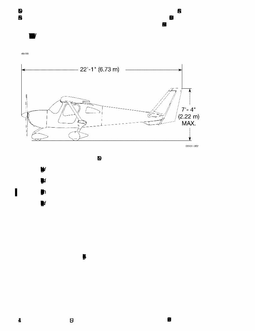
THREE VIEW - NORMAL GROUND ATTITUDE
Figure 1-1* (Sheet 1 of 2)
1-3162PHUS-01
SECTION 1 CESSNAGENERAL MODEL 162
GARMIN G300
U.S.
THREE VIEW - NORMAL GROUND ATTITUDE
NOTE
• Wing span shown with standard strobe lights installed.
• Wheel base length is 62.40 inches (1.58 m).
• Propeller ground clearance is 8.50 inches (215.90 mm).
• Wing area is 120.0 square feet (11.15 sq. m).
Figure 1-1* (Sheet 2)
162PHUS-011-4

CESSNA SECTION 1MODEL 162 GENERALGARMIN G300
U.S.
INTRODUCTION
This POH contains 10 sections, and includes the material required tobe furnished to the pilot by American Society for Testing and MaterialsInternational (ASTM) standards F2245 for Light Sport Aircraft (LSA). Italso contains supplemental data supplied by Cessna Aircraft Company.
Section 1 provides basic data and information of general interest.
DESCRIPTIVE DATA
ENGINE
Number of Engines: 1Engine Manufacturer: Teledyne Continental MotorsEngine Model Number: O-200-DEngine Type: Normally aspirated, direct drive, air-cooled, horizontally
opposed, carburetor equipped, four cylinder engine with201.0 cu. in. displacement.
Horsepower Rating and Engine Speed: 100 rated BHP at 2750 RPM
PROPELLER
Propeller Manufacturer: McCauley Propeller SystemsPropeller Model Number: 1A162/TCD6754Number of Blades: 2Propeller Diameter: 67 inches (1.70 m)Propeller Type: Fixed Pitch
(Continued Next Page)
1-5162PHUS-01

SECTION 1 CESSNAGENERAL MODEL 162
GARMIN G300
U.S.
DESCRIPTIVE DATA (Continued)
FUEL
WARNING
USE OF UNAPPROVED FUELS MAY RESULT INDAMAGE TO THE ENGINE AND FUEL SYSTEMCOMPONENTS, RESULTING IN POSSIBLE ENGINEFAILURE.
Approved Fuel Grades (and Colors):100LL Grade Aviation Fuel (Blue)100 Grade Aviation Fuel (Green)
NOTE
Isopropyl alcohol or Diethylene Glycol Monomethyl Ether(DiEGME) may be added to the fuel supply in accordanceto TCM Service Information Letter (SIL99-2B). Refer toSection 8 for additional information.
FUEL CAPACITYTotal Capacity . . . . . . . . . . . . . . . . . 25.46 U.S. GALLONS (96.34 l)Total Usable . . . . . . . . . . . . . . . . . . . 24.00 U.S. GALLONS (90.82 l)Total Capacity Each Tank . . . . . . . . 12.73 U.S. GALLONS (48.17 l)Total Usable Each Tank . . . . . . . . . . 12.00 U.S. GALLONS (45.41 l)
NOTE
• To ensure maximum fuel capacity and minimizecrossfeeding when refueling, always park the airplane ina wings level, normal ground attitude. Refer to Figure 1-1 for normal ground attitude dimensions.
• The fuel filler assembly is equipped with indicator tabsfor 3/4, 1/2 and 1/4 fuel quantities.
• Maximum full capacity is indicated when fuel reaches theupper hole of the indicator tab. This fuel level allows forproper thermal expansion. Filling the fuel tank above theupper hole eliminates expansion space resulting in fuelventing overboard through the fuel vent.
(Continued Next Page)
162PHUS-001-6
CESSNA SECTION 1MODEL 162 GENERALGARMIN G300
U.S.
DESCRIPTIVE DATA (Continued)
OIL
OIL SPECIFICATION
SAE J1966 Aviation Grade Non-Dispersant Mineral Oil: Used when theairplane was delivered from the factory and should be used to replenishthe supply during the first 25 hours. This oil should be drained and thefilter changed after the first 25 hours of operation. Refill the engine withSAE J1966 Aviation Grade Non-Dispersant Mineral Oil and continue touse until a total of 50 hours has accumulated or oil consumption hasstabilized.
SAE J1899 Aviation Grade Ashless Dispersant Oil: Oil conforming toTeledyne Continental Motors (TCM) Service Information Letter SIL99-2B, and all revisions and supplements thereto, must be used after first50 hours or oil consumption has stabilized.
RECOMMENDED VISCOSITY FOR TEMPERATURE RANGE
Multiviscosity or straight grade oil may be used throughout the year forengine lubrication. Refer to the following table for temperature versusviscosity ranges.
NOTE
When operating temperatures overlap, use the lightergrade of oil.
OIL CAPACITYSump. . . . . . . . . . . . . . . . . . . . . . . . . . . . . 5.0 U.S. QUARTS (4.73 l)Total. . . . . . . . . . . . . . . . . . . . . . . . . . . . . . 5.5 U.S. QUARTS (5.20 l)Minimum Operating Quantity . . . . . . . . . . 3.5 U.S. QUARTS (3.31 l)
(Continued Next Page)
Temperature
SAE J1966Non-Dispersant
Mineral OilSAE Grade
SAE J1899Ashless Dispersant Oil
SAE Grade
Above 4°C (40°F) 50 50 or 15W-50 or 25W-60
Below 4°C (40°F) 30 30 or 15W-50 or 25W-60
All Temperatures M20W-50 15W-50, 20W- 50 or 25W-60
1-7162PHUS-00

SECTION 1 CESSNAGENERAL MODEL 162
GARMIN G300
U.S.
DESCRIPTIVE DATA (Continued)
MAXIMUM CERTIFICATED WEIGHTSRamp Weight:. . . . . . . . . . . . . . . . . . . . . . . . 1324 POUNDS (600.6 kg)Takeoff Weight . . . . . . . . . . . . . . . . . . . . . . . 1320 POUNDS (598.8 kg)Landing Weight . . . . . . . . . . . . . . . . . . . . . . 1320 POUNDS (598.8 kg)
MAXIMUM WEIGHT IN BAGGAGE COMPARTMENTBaggage Area (Station 155 to 190) . . . . . . . 50 POUNDS (22.68 kg)
STANDARD AIRPLANE WEIGHTSStandard Empty Weight . . . . . . . . . . . . . . . . . 834 POUNDS (378.3 kg)Maximum Useful Load . . . . . . . . . . . . . . . . . . 486 POUNDS (220.4 kg)
CABIN AND ENTRY DIMENSIONS
Detailed dimensions of the cabin interior and entry door openings areillustrated in Section 4.
BAGGAGE SPACE AND ENTRY DIMENSIONS
Dimensions of the baggage area are illustrated in detail in Section 4.
SPECIFIC LOADINGSWing Loading . . . . . . . . . . . . . . . . . . . . . 11.0 lbs/sq. ft. (53.7 kg/sq. m)Power Loading . . . . . . . . . . . . . . . . . . . . . . . . . . . . . . . . . . .13.2 lbs/HP
162PHUS-011-8

CESSNA SECTION 2MODEL 162 AIRPLANE AND SYSTEM DESCRIPTIONGARMIN G300
AIRPLANE AND SYSTEMS DESCRIPTION
TABLE OF CONTENTSPage
Introduction . . . . . . . . . . . . . . . . . . . . . . . . . . . . . . . . . . . . . . . . . . . .2-3Airframe . . . . . . . . . . . . . . . . . . . . . . . . . . . . . . . . . . . . . . . . . . . . . . .2-3Flight Controls . . . . . . . . . . . . . . . . . . . . . . . . . . . . . . . . . . . . . . . . . .2-3Instrument Panel, Flight and System Instruments . . . . . . . . . . . . . . .2-5Landing Gear and Brake System. . . . . . . . . . . . . . . . . . . . . . . . . . . .2-6Miscellaneous Cabin Features . . . . . . . . . . . . . . . . . . . . . . . . . . . . .2-7Engine . . . . . . . . . . . . . . . . . . . . . . . . . . . . . . . . . . . . . . . . . . . . . . . 2-8
Engine Controls . . . . . . . . . . . . . . . . . . . . . . . . . . . . . . . . . . . . . . .2-8Engine Instruments . . . . . . . . . . . . . . . . . . . . . . . . . . . . . . . . . . . .2-9Tachometer (RPM) . . . . . . . . . . . . . . . . . . . . . . . . . . . . . . . . . . . . .2-9Oil Pressure (OIL PSI) . . . . . . . . . . . . . . . . . . . . . . . . . . . . . . . . .2-10Oil Temperature (OIL °F) . . . . . . . . . . . . . . . . . . . . . . . . . . . . . . . 2-11Exhaust Gas Temperature (EGT °F) (if installed) . . . . . . . . . . . . . 2-11Carburetor Temperature (CARB °F) . . . . . . . . . . . . . . . . . . . . . .2-12New Engine Break-In And Operation . . . . . . . . . . . . . . . . . . . . . .2-12Engine Lubrication System. . . . . . . . . . . . . . . . . . . . . . . . . . . . . .2-13Ignition And Starter System . . . . . . . . . . . . . . . . . . . . . . . . . . . . .2-13Air Induction System. . . . . . . . . . . . . . . . . . . . . . . . . . . . . . . . . . .2-14Exhaust System . . . . . . . . . . . . . . . . . . . . . . . . . . . . . . . . . . . . . .2-14Cooling System. . . . . . . . . . . . . . . . . . . . . . . . . . . . . . . . . . . . . . .2-14
Propeller . . . . . . . . . . . . . . . . . . . . . . . . . . . . . . . . . . . . . . . . . . . . .2-15Fuel System. . . . . . . . . . . . . . . . . . . . . . . . . . . . . . . . . . . . . . . . . . .2-15
Fuel Distribution . . . . . . . . . . . . . . . . . . . . . . . . . . . . . . . . . . . . . .2-15Fuel Indicating System . . . . . . . . . . . . . . . . . . . . . . . . . . . . . . . . .2-16Fuel Venting . . . . . . . . . . . . . . . . . . . . . . . . . . . . . . . . . . . . . . . . .2-17Reduced Tank Capacity . . . . . . . . . . . . . . . . . . . . . . . . . . . . . . . .2-18Fuel Drain Valves . . . . . . . . . . . . . . . . . . . . . . . . . . . . . . . . . . . . .2-19
U.S.162PHUS-01 2-1

SECTION 2 CESSNAAIRPLANE AND SYSTEM DESCRIPTION MODEL 162
GARMIN G300
U.S.
TABLE OF CONTENTSPage
Electrical System . . . . . . . . . . . . . . . . . . . . . . . . . . . . . . . . . . . . . . 2-19Master Switch . . . . . . . . . . . . . . . . . . . . . . . . . . . . . . . . . . . . . . . 2-21Electrical System Monitoring . . . . . . . . . . . . . . . . . . . . . . . . . . . . 2-21Main Battery Current (Amps). . . . . . . . . . . . . . . . . . . . . . . . . . . . 2-21System Voltage (Volts) . . . . . . . . . . . . . . . . . . . . . . . . . . . . . . . . 2-21Circuit Breakers . . . . . . . . . . . . . . . . . . . . . . . . . . . . . . . . . . . . . . 2-2212V Power Outlet . . . . . . . . . . . . . . . . . . . . . . . . . . . . . . . . . . . . 2-23External Power Receptacle (if installed) . . . . . . . . . . . . . . . . . . . 2-23
Lighting Systems . . . . . . . . . . . . . . . . . . . . . . . . . . . . . . . . . . . . . . 2-24Exterior Lighting. . . . . . . . . . . . . . . . . . . . . . . . . . . . . . . . . . . . . 2-24Interior Lighting . . . . . . . . . . . . . . . . . . . . . . . . . . . . . . . . . . . . . 2-24
Cabin Heating and Ventilating System . . . . . . . . . . . . . . . . . . 2-25/2-26Stall Warning System . . . . . . . . . . . . . . . . . . . . . . . . . . . . . . . 2-25/2-26
162PHUS-012-2

CESSNA SECTION 2MODEL 162 AIRPLANE AND SYSTEM DESCRIPTIONGARMIN G300
U.S.
INTRODUCTION
This section provides description and operation of the airplane and itssystems. Some equipment described herein is optional and may not beinstalled in the airplane. Refer to Section 10, Supplements, for detailsof other optional systems and equipment.
AIRFRAME
The airplane is an all metal, two-place, high wing, single-engineairplane equipped with tricycle landing gear and is designed for sportflying and introductory training purposes.
The sheet metal fuselage bulkhead, stringer, and skin semi-monocoque construction provide safe and comfortable environment forpilot, passenger, and baggage. Forward pivoting seats allow access tothe baggage area. Wing struts and main landing gear legs attach to anI-beam structure under the baggage area behind the seats. Nose gearand engine mount assembly attach to the firewall separating the cabinfrom engine compartment.
The aft fuselage empennage (tail assembly) consists of horizontal andvertical stabilizers, the rudder, a left elevator, and a right elevator withelevator trim tab. Attaching on either side the fuselage above the cabin,the wing contains fuel tanks at the wing root between the forward andaft spars. Aft of the rear wing spar are mounted the flaps (inboard) andailerons (outboard). In addition to the fuselage carry-through spars, thewing is attached by forward-spar-to-fuselage struts. The wing,empennage, and flight control surfaces are also made of sheet metalspars, ribs, and skin semi-monocoque construction with balanceweights incorporated into the rudder, elevators, and ailerons.
FLIGHT CONTROLS
The airplane's flight control system consists of conventional aileron,rudder, and elevator control surfaces manually operated through acable system. An elevator trim tab is located on the right elevator. Trimtab operation is by direct linkage to a elevator mounted electric servomotor controlled by a control stick mounted trim switch. Elevator trimtab position is displayed on the Engine Indicating System area of theG300 display.
(Continued Next Page)
162PHUS-01 2-3

SECTION 2 CESSNAAIRPLANE AND SYSTEM DESCRIPTION MODEL 162
GARMIN G300
U.S.
FLIGHT CONTROLS (Continued)
Dual under panel control sticks are used for aileron and elevatorcontrol. The under panel control sticks mimic the control movement of afloor mounted control stick while providing ease of entry to the cabin.The control stick location is designed so that the pilot's hand naturallyfalls on the control stick with the outboard arm on the door arm rest.
Rudder pedals with toe brakes provide rudder control through forwardand aft individually adjustable pilot and copilot pedal assemblies.Rudder pedals should be adjusted so that it is possible to have fullbrake pedal deflection when the same side rudder is fully deflected.
Wing flaps are manually operated down by a flap handle locatedbetween the seats and returned to faired UP position by air load andreturn spring assist. Flap detent position UP, 10º, 25º, or FULL may beselected only after depressing the release button in the end of the flaphandle.
A control gust lock is provided. The control lock pins the left controlstick through a bracket to immobilize the ailerons and elevator. Rudderis held centered by the springs used for increasing rudder pedal force.
During the preflight walk-around inspection it is possible to move theailerons into an over-centered position by moving the aileron downfrom the centered or faired with the flaps UP flaps position. The down-deflected aileron may appear to be stuck or difficult to move up. This isnormal characteristic of the Cessna 162 ailerons system that onlyoccurs when the ailerons are moved down from outside the airplane. Itis recommended that the aileron movement be checked by moving theailerons up from the flaps UP faired position then returned to thisposition. However if an aileron is externally moved down and becomesover-centered, simply re-center the cockpit control stick and continuethe walk-around inspection.
CAUTION
AILERON OVER CENTERING ONLY OCCURS WHENAILERONS ARE MOVED FROM OUTSIDE THEAIRPLANE. CONTROL STICK STIFFNESS OR STICKINGIN ANY DIRECTION OF ANY CONTROL SURFACE THISIS NOT NORMAL AND SHOULD BE INSPECTED BYMAINTENANCE PERSONNEL PRIOR TO FLIGHT.
162PHUS-012-4

CESSNA SECTION 2MODEL 162 AIRPLANE AND SYSTEM DESCRIPTIONGARMIN G300
U.S.
INSTRUMENT PANEL, FLIGHT AND SYSTEMINSTRUMENTS
NOTE
Refer to the Garmin Pilot's Guide for details and operatinginstructions of the G300 Avionics System.
The Model 162 Skycatcher instrument panel is oriented around theGarmin G300 Flight and Engine Instrumentation Display(s). Directly infront of the pilot is the G300 Primary Flight Display (PFD) which has allflight, navigation, and engine instruments depicted in an electronicformat on a liquid crystal display. A vast amount of additional flight andnavigational information is accessible through the G300 system’svarious selectable pages. Left of the PFD on the upper panel is theoptional autopilot controller unit (if installed) and below it is the Ignition/Magneto key switch.
The electrical system switch/circuit breaker panel, located to the right ofthe PFD, has switches in the top row with two rows of circuit breakersunderneath. On the right end of the switch row is the PANEL LIGHTcontrol knob. Under the electrical system panel is the radio stack withthe Garmin SL40 Communication radio over the Garmin 327GXTTransponder.
An optional Garmin Multifunction Display (MFD) (if installed) is locatedto the right of the electrical system switch/circuit breaker panel. TheMFD (when installed) takes over the moving map and engineinstrument functions from the PFD as well as other display pagefunctions. On the far right side of the panel is the remote ELT switchand optional intercom control panel.
Engine controls are located below the radio stack and MFD display (ifinstalled) along the bottom center of the instrument panel. The controlsare (left to right): Carb Heat, Throttle Control, Mixture Control, andCabin Heat Control. The parking brake and fuel shut-off control knobsare located beneath the engine controls on the top of the verticalpedestal. Headset jacks and auxiliary 12 volt cabin power outlet arepositioned further down on the vertical pedestal.
(Continued Next Page)
162PHUS-01 2-5

SECTION 2 CESSNAAIRPLANE AND SYSTEM DESCRIPTION MODEL 162
GARMIN G300
U.S.
INSTRUMENT PANEL, FLIGHT AND SYSTEMINSTRUMENTS (Continued)
Behind the instrument panel are the servo units for the optionalautopilot, Garmin ADAHRS (Air Data, Attitude, and Heading ReferenceSystem) Unit, and the Secondary Battery. The ADAHRS unit is amultifunctional processing unit which takes pitot-static pressures fromthe pitot tube on the left wing and the static source button aft of the leftcowl for altitude, airspeed, and vertical speed information, tailconemounted magnetometer data for heading, and engine data for displayon the Engine Indication System (EIS) portion of the displays.
Fuel indicators are mounted in each wing root with silver float balls forvisual ease. The fuel placards are differentiated between level-flight(LVL FLT) and on-ground (GRND). The MIN/TO reference mark on theGRND side indicates the ¼ fuel requirement for take-off. In-tank fueltabs are equipped with indicator holes for full, ¾, ½, and the bottom ofthe tab indicates ¼ (minimum takeoff). See Fuel System descriptionsection for more information.
The optional magnetic compass (if installed) is mounted to the airplanestructure above the center of the windshield.
LANDING GEAR AND BRAKE SYSTEM
The tricycle type landing gear on the Model 162 features tapered springsteel main gear legs and a spring steel nose gear with elastimetricpucks for shock absorption. The nose gear is free-castoring anddirectional control is done via differential braking. This permits very tightturning and maneuvering in confined spaces. Full rudder deflection canassist directional control when taxiing.
Disc brakes located on the main gear wheels are hydraulically actuatedby master cylinders on each rudder pedal. A parking brake valve locksbrake pressure to the disc calipers when the parking brake handle onthe lower instrument is pulled with the brake pedals depressed. Thehydraulic brake system is connected in series running from the firewallmounted reservoir to the copilot's master cylinder then to the pilot'smaster cylinder then to the brake caliper through the parking brakevalve.
162PHUS-012-6

CESSNA SECTION 2MODEL 162 AIRPLANE AND SYSTEM DESCRIPTIONGARMIN G300
U.S.
MISCELLANEOUS CABIN FEATURES
The cabin is accessed through gas-cylinder assisted doors hinged atthe top. In this manner, the doors swing up and out of the way for easeof entry and loading of cargo. Proper operation and care of the cabindoors will ensure years of flying enjoyment.
CAUTION
THE CABIN DOORS SHOULD NOT BE SLAMMED. THEDOORS DO NOT USE A PRE-CATCH MECHANISM ANDSHOULD NOT BE SLAMMED CLOSED AS THIS WILLONLY ACCELERATE WEAR ON THE DOOR ASSEMBLY.
Doors should be latched from inside by pulling the door closed andwhile holding the door closed, articulating the door latch handle asindicated by the placard. Externally, the door latch handle is operatedthrough a vertical arc as indicated by the placard. Pulling the externalhandle horizontally may damage the mechanism and door.
The baggage area is accessed by tilting the seats forward and canaccommodate up to 50 pounds of cargo. Tie-down rings are supplied tosecure cargo. A tailcone close-out net is installed separating thebaggage area from the aft tailcone. The net is easily removed formaintenance access but it must be installed for flight to prevent anyloose objects or baggage from migrating into the tailcone area causingcontrol and/or center of gravity issues.
Fire Extinguisher is installed for easy reach behind the cabin seats inthe baggage area. Extinguisher charge should be checked as part ofeach preflight inspection.
162PHUS-01 2-7

SECTION 2 CESSNAAIRPLANE AND SYSTEM DESCRIPTION MODEL 162
GARMIN G300
U.S.
ENGINE
The airplane is powered by a normally aspirated, direct drive, air-cooled, horizontally opposed, carbureted four cylinder engine with awet sump lubrication system. The engine is a Teledyne Continental O-200-D rated at 100 horsepower at 2750 RPM. Major accessoriesinclude a starter, gear-driven alternator, dual magnetos and a full flowoil filter mounted on the rear of the engine accessory case.
ENGINE CONTROLS
Engine power is set using the throttle control. The throttle control is asmooth black knob located at the center of the instrument panel. Thethrottle control is configured so that the throttle is open in the forwardposition and closed in the full aft position. A friction lock, located at thebase of the throttle control knob, is operated by rotating the lockclockwise to increase friction or counterclockwise to decrease friction.
Engine fuel mixture is controlled by the mixture control. The mixturecontrol is a red knob, with raised points around the circumference,located immediately to the right of the throttle control and is equippedwith a lock button in the end of the knob. The rich position is fullforward, and full aft is the idle cutoff position. For small adjustments, thecontrol may be moved forward by rotating the knob clockwise, and aftby rotating the knob counterclockwise. For rapid or large adjustments,the knob may be moved forward or aft by depressing the lock button inthe end of the mixture control knob, and then positioning the control asdesired.
(Continued Next Page)
162PHUS-012-8

CESSNA SECTION 2MODEL 162 AIRPLANE AND SYSTEM DESCRIPTIONGARMIN G300
U.S.
ENGINE (Continued)
ENGINE INSTRUMENTS
The G300 Engine Indication System (EIS) provides the pilot graphicalindicators and numerical values for Tachometer (RPM), Oil Pressure(OIL PSI), Oil Temperature (OIL ºF), Carburetor Temperature (CARBºF), Battery Current (AMPS), and Elevator Trim Position (TRIM) alongthe top of the appropriate G300 Display. Additional indicators andnumerical values for Exhaust Gas Temperature (EGT ºF), ElectricalBus Voltage (VOLTS), and Engine Hours (ENG HRS) are displayed onthe G300 ENGINE Page when selected. In normal operation, EISinformation is displayed on the Primary Flight Display (PFD) in thesingle display installation and on the optional Multifunction Display(MFD) in the dual display configuration (if installed). During engine startor when the AVN MASTER is OFF, the EIS is only displayed on thePFD even if the optional MFD is installed.
TACHOMETER (RPM)
A speed sensor, mounted on the right magneto, provides a digitalsignal to the ADAHRS which processes and outputs the RPM data tothe EIS.
Engine speed (RPM) is shown by the tachometer indicator found on allEIS pages. The tachometer indicator uses a circular scale with movingpointer and a digital value. The pointer moves through a range from 0to 3000 RPM. The numerical RPM value is displayed in increments of10 RPM in white numerals below the pointer.
The normal engine speed operating limit (top of green arc) is 2750RPM. When engine speed is more than 2750 RPM, the pointer, digitalvalue, and label (RPM) turn red to show engine speed is more than thelimit. The digital value and label (RPM) will flash. A red-X is displayedwhen the instrument is invalid or out of the data range.
(Continued Next Page)
162PHUS-00 2-9

SECTION 2 CESSNAAIRPLANE AND SYSTEM DESCRIPTION MODEL 162
GARMIN G300
U.S.
ENGINE (Continued)
ENGINE INSTRUMENTS (Continued)
OIL PRESSURE (OIL PSI)
The oil pressure transducer, connected to the engine forward oilpressure port, provides a signal to the engine display that is processedand shown as oil pressure.
Engine oil pressure is shown on all EIS pages. The analog instrumentrange is 0 to 110 PSI with digital information range from 0 to 140 PSI.The instrument has a red band from 0 to 10 PSI (low warning), a yellowband from 10 to 30 PSI (low caution), a green band from 30 to 60 PSI(normal operating range), a yellow band from 60 to 100 PSI (highcaution) and a red band from 100 to 110 PSI (high warning). A whitepointer indicates actual oil pressure.
When oil pressure is 0 to 10 PSI or 100 to 140 PSI, the pointer, digitalvalue, and label (OIL PRES) will change to red to show that oil pressureis outside normal limits. A red-X is displayed when the instrument isinvalid or out of the data range.
When the engine speed (RPM) is in the green arc and the oiltemperature is in the green band, the oil pressure should be in thegreen band. If oil pressure is below the green band or above the greenband, adjust the engine speed to maintain adequate oil pressure. Whenengine speed is at idle or near idle, the oil pressure indication must beabove the lower red band. With the engine at normal operating oiltemperature, and engine speed at or close to idle, oil pressure belowthe green band, but above the lower red band, is acceptable.
In cold weather, the oil pressure will initially be high (close to the upperred band when the engine is started). As the engine and oil warm up,the oil pressure will come down into the green band range.
(Continued Next Page)
162PHUS-002-10

CESSNA SECTION 2MODEL 162 AIRPLANE AND SYSTEM DESCRIPTIONGARMIN G300
U.S.
ENGINE (Continued)
ENGINE INSTRUMENTS (Continued)
OIL TEMPERATURE (OIL °F)
The oil temperature sensor is installed in the engine oil filter adapterand provides a signal to the engine display that is processed andshown as oil temperature.
Engine oil temperature is shown on all EIS pages. The instrumentrange is 0 to 250°F with digital information range from 30 to 265°F. Theinstrument has a yellow band from 0 to 75°F (low caution), a greenband from 75 to 220°F (normal operating range), a yellow band from220 to 240°F (high caution) and a red band from 240 to 265°F (highwarning). A white pointer indicates actual oil temperature.
When oil temperature is in the red band, 240 to 265°F, the pointer andOIL TEMP turn red and flash to show oil temperature is higher than thelimit. A red-X is displayed when the instrument is invalid or out of thedata range.
EXHAUST GAS TEMPERATURE (EGT °F) (if installed)
A thermocouple installed in the exhaust down pipe measures EGT andprovides a signal to the engine display that is processed and shown onthe EIS ENGINE page by the EGT °F vertical tape display and digitalinformation. The tape indicator range is from 1000 to 1600°F, and thedigital information range is from 1000 to 2000°F. The white pointerindicates actual EGT temperature. Red digits are shown for values lessthan 0°F and more than 2000°F. A red-X is displayed when theinstrument is invalid or out of the data range.
(Continued Next Page)
162PHUS-01 2-11

SECTION 2 CESSNAAIRPLANE AND SYSTEM DESCRIPTION MODEL 162
GARMIN G300
U.S.
ENGINE (Continued)
ENGINE INSTRUMENTS (Continued)
CARBURETOR TEMPERATURE (CARB °F)
Carburetor temperature is provided as a reference to determine thepotential for carburetor ice formation. The CARB °F indication isprovided on vertical tape and in digital form on the right side of the EISdisplay atop the PFD and on the G300 ENGINE page. The tape displayrange is from 20 to 80°F and the digital indication range is from -40°F to100°F. A yellow caution range is depicted from 5°F to 40°F. A red-X isdisplayed when the instrument is invalid or out of the data range.
NOTE
Although carburetor ice is more likely to form attemperatures within the yellow band range, it can form attemperatures outside the yellow caution range. If engineroughness or unexplained RPM loss is encountered, fullcarburetor heat should be immediately applied.
NEW ENGINE BREAK-IN AND OPERATION
The initial engine run-in was accomplished at the factory and is readyfor the full range of use. It is recommended that cruising beaccomplished at 75% power as much as practicable until a total of 50hours has accumulated or oil consumption has stabilized. This willensure proper seating of the piston rings. Low cruise power settingsshould be used for extended descents during the first 25 hours of newengine operations. Avoid extended descents with reduced powersettings.
(Continued Next Page)
162PHUS-012-12

CESSNA SECTION 2MODEL 162 AIRPLANE AND SYSTEM DESCRIPTIONGARMIN G300
U.S.
ENGINE (Continued)
ENGINE LUBRICATION SYSTEM
The engine utilizes a full pressure, wet sump type lubrication systemwith aviation grade oil as the lubricant. The capacity of the enginesump, located on the bottom of the engine, along with the engine oilfilter and oil cooler is 5.5 quarts. Oil is drawn from the sump through afilter screen on the end of a pickup tube to the engine driven oil pump.Oil from the pump then passes through a full-flow oil filter, a pressurerelief valve at the rear of the right oil gallery, and an oil cooler beforelubricating engine parts. The oil returns to the sump by gravity. The filteradapter in the full-flow filter is equipped with a bypass valve which willcause lubricating oil to bypass the filter in the event the filter becomesplugged, or the oil temperature is extremely cold.
An oil dipstick/filler tube is located at the left rear of the engine case.The oil dipstick/filler tube is accessed through a door located on the leftside of the engine cowling. The engine should not be operated on lessthan 3.5 quarts of oil. For extended flight, fill to 5.0 quarts (dipstickindication only). For engine oil grade and specifications, refer toSection 8 of this POH.
IGNITION AND STARTER SYSTEM
Engine ignition is provided by two engine driven magnetos, and twospark plugs in each cylinder. The left magneto fires the lower left andlower right spark plugs, and the right magneto fires the upper left andupper right spark plugs. Normal operation is conducted with bothmagnetos due to the more complete burning of the fuel/air mixture withdual ignition.
Ignition and starter operation is controlled by a rotary-type switchlocated on the left instrument panel. The MAGNETOS switch is labeledclockwise, OFF, R, L, BOTH, and START. The engine should beoperated on both magnetos (BOTH position) except for magnetochecks. The R and L positions are for checking purposes andemergency use only. When the MAGNETOS switch is rotated to thespring-loaded START position, with the MASTER switch in the ONposition, the starter contactor is closed and the starter, now energized,will crank the engine. When the switch is released, it will automaticallyreturn to the BOTH position.
(Continued Next Page)
162PHUS-00 2-13

SECTION 2 CESSNAAIRPLANE AND SYSTEM DESCRIPTION MODEL 162
GARMIN G300
U.S.
ENGINE (Continued)
AIR INDUCTION SYSTEM
The engine air induction system receives ram air through an intake onthe lower front portion of the engine cowling. The intake is covered byan air filter which removes dust and other foreign matter from theinduction air. Airflow passing through the filter enters an air box, whichis equipped with a cable operated air door for cold air or pre-heated airfrom a shroud around the exhaust for carburetor heat. The pre-heatedair is also the source for alternate air if the air induction filter shouldbecome blocked. The pre-heated air is unfiltered and drawn through ascat tube in the cylinder baffles. Use of full carburetor heat at fullthrottle will result in a loss of approximately 200-250 RPM due to theincreased intake temps. After passing through the air box, induction airenters a carburetor under the engine, and is then ducted to the enginecylinders through intake manifold tubes.
EXHAUST SYSTEM
Exhaust gas from each cylinder passes through a riser assembly to acommon muffler, located below the engine, and then overboard througha single exhaust outlet. Outside air is supplied to a shroud constructedaround the outside of the muffler to form a heating chamber. The airheated by the shroud is then supplied to the cabin.
COOLING SYSTEM
Ram air for engine cooling enters through two intake openings in thefront of the engine cowling. The cooling air is directed from above theengine, around the cylinders and other areas of the engine by baffling,and then exits through an opening at the bottom aft edge of the enginecowling.
A winterization kit is available for the airplane. Refer to Section 10,Supplement 4 for description and operating information.
162PHUS-012-14

CESSNA SECTION 2MODEL 162 AIRPLANE AND SYSTEM DESCRIPTIONGARMIN G300
U.S.
PROPELLER
The airplane is equipped with a two bladed, fixed pitch, one-pieceforged aluminum alloy propeller which is anodized to retard corrosion.The propeller is 67 inches in diameter.
FUEL SYSTEM
The airplane fuel system, Refer to Figure 2-6, consists of two ventedintegral fuel tanks (one tank in each wing), fuel shutoff valve, and a fuelstrainer. The engine-mounted portion of the system consists of thegravity-fed updraft float carburetor.
WARNING
UNUSABLE FUEL LEVELS FOR THIS AIRPLANE WEREDETERMINED IN ACCORDANCE WITH ASTMINTERNATIONAL COMPLIANCE STANDARDS.FAILURE TO OPERATE THE AIRPLANE INCOMPLIANCE WITH FUEL LIMITATIONS SPECIFIED INSECTION 3 MAY FURTHER REDUCE THE AMOUNT OFFUEL AVAILABLE IN FLIGHT.
FUEL QUANTITY DATA IN U.S. GALLONS
FUEL DISTRIBUTION
Fuel flows by gravity from the two wing tanks to a fuel shutoff valve, thefuel strainer, and to the carburetor. The carburetor meters fuel flow inproportion to induction air flow and distributes to the cylinder intakemanifold.
(Continued Next Page)
FUEL TANKS
FUEL LEVEL (QUANTITY
EACH TANK)TOTAL FUEL
TOTAL UNUSABLE
TOTAL USABLEALL FLIGHT CONDITIONS
Two Full (12.73) 25.46 1.46 24.0
Figure 2-1
162PHUS-01 2-15
SECTION 2 CESSNAAIRPLANE AND SYSTEM DESCRIPTION MODEL 162
GARMIN G300
U.S.
FUEL SYSTEM (Continued)
FUEL INDICATING SYSTEM
Fuel quantity is measured by two sight gages located in each wing rootjust forward and above the cabin door opening. The sight gages arevented and include orifice fittings at the top and bottom of the sighttube. The fuel levels are aided with floating aluminum balls forincreased readability. There are two scales displayed on each fuel sightgage. The aft scale shows fuel levels to be read in level flight. Themarkings should not be relied upon for accurate readings during skids,slips or unusual attitudes. The forward scale shows fuel levels as readon level ground. Minimum takeoff is indicated when the center of theball is at the "MIN/TO" line on the forward scale in level ground attitudewhich represents 3 gallons per side or 6 gallons total (1/4 tanks)..
(Continued Next Page)
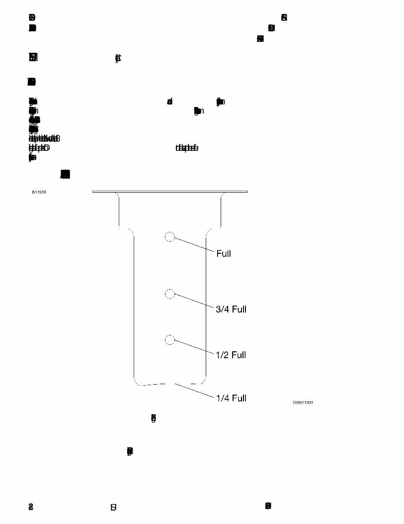
FUEL QUANTITY SIGHT GAGE
Figure 2-2*
162PHUS-012-16

CESSNA SECTION 2MODEL 162 AIRPLANE AND SYSTEM DESCRIPTIONGARMIN G300
U.S.
FUEL SYSTEM (Continued)
FUEL INDICATING SYSTEM (Continued)
An empty tank is shown on the fuel quantity indicator as a red line onthe aft (Level Flight) scale along with the “E” indication. When anindicator shows an empty tank, approximately 0.73 gallons of unusablefuel remain in the tank. The fuel gage shows the fuel available in thetank up to the limit of the gage measurement range of approximately ¾tank. At this level, additional fuel may be available, but no additionalindication of the fuel will be visible. A visual check of each wing tankfuel level must be performed prior to each flight. Compare the visualfuel level and indicated fuel quantity to accurately estimate usable fuel.
WARNING
TAKEOFF IS PROHIBITED IF EITHER FUEL SIGHTGAGE INDICATES BELOW THE MIN/TO INDICATION(LESS THAN 1/4 TANK) OR BELOW THE BOTTOM OFTHE IN-TANK FUEL FILLER INDICATOR TAB.
FUEL VENTING
Fuel system venting is essential to system operation. Completeblockage of the fuel venting system will result in decreasing fuel flowand eventual engine stoppage. The fuel venting system consists of aninterconnecting vent line between the fuel tanks and a check valveequipped overboard vent in the left fuel tank assembly. The overboardvent protrudes from the bottom surface of the left wing, just inboard ofthe wing strut upper attachment point. The fuel filler caps are vacuumvented; the fuel filler cap vents will open and allow air to enter the fueltanks in case the overboard vents become blocked.
(Continued Next Page)
162PHUS-01 2-17
SECTION 2 CESSNAAIRPLANE AND SYSTEM DESCRIPTION MODEL 162
GARMIN G300
U.S.
FUEL SYSTEM (Continued)
REDUCED TANK CAPACITY
The airplane may be serviced to a reduced capacity to permit heaviercabin loadings. This is accomplished by filling each tank to the bottomedge of the fuel filler indicator tab, thus giving a reduced fuel load of 3gallons usable (minimum takeoff fuel) in each tank. Continued filling toeach subsequent hole in the indicator tab will add an additional 3gallons usable fuel per tank. Do not fuel above top hole as fuelexpansion may cause overflow from fuel vent.
IN-TANK FUEL FILLER INDICATOR TAB
(Continued Next Page)
Figure 2-3*
162PHUS-012-18

CESSNA SECTION 2MODEL 162 AIRPLANE AND SYSTEM DESCRIPTIONGARMIN G300
U.S.
FUEL SYSTEM (Continued)
FUEL DRAIN VALVES
The fuel system is equipped with 6 drain valves (4 in the wings and 2 inthe lower cowl) to provide a means for the examination of fuel in thesystem for contamination and grade. The system should be examinedbefore each flight and after each refueling, by using the sampler cupprovided to drain fuel from each wing tank sump, the lower cowl fuelshutoff valve drain and the fuel strainer sump lower cowl drain. If anyevidence of fuel contamination is found, it must be eliminated inaccordance with the preflight inspection checklist and the discussion inSection 8. If takeoff weight limitations for the next flight permit, the fueltanks should be filled after each flight to prevent condensation.
ELECTRICAL SYSTEM
The airplane is equipped with a 14-volt direct current (DC) electricalsystem powered by an engine driven alternator. A 12-volt main storagebattery is located on the right forward side of the firewall. The alternatorand main battery are controlled by the MASTER switch found on theswitch/circuit breaker panel.
The alternator and main battery power is supplied to a relay panellocated on the left forward side of the firewall. Power for all electricalcircuits, except the secondary power circuit, is supplied from the relaypanel to the electrical bus located in the switch/circuit breaker panel.The electrical bus is supplied with power anytime the MASTER switchis turned on. The electrical bus provides power to the avionics busthrough the AVN MASTER switch. The avionics bus is supplied withpower anytime the MASTER switch and AVN MASTER switch areturned on.
The electrical system is equipped with a secondary battery locatedbetween the firewall and the instrument panel. This secondary batterysupplies power to the secondary power circuit for PANEL LIGHTSdimming as well as stable power to the G300 avionics and displaysduring engine start. This prevents undesired panel light dimming andloss of G300 information resulting from voltage drop during the enginestart. The secondary battery is also controlled by the MASTER switchfound on the switch/circuit breaker panel. Power is supplied toequipment on the secondary power circuit anytime the MASTER switchis turned on.
(Continued Next Page)
162PHUS-01 2-19

SECTION 2 CESSNAAIRPLANE AND SYSTEM DESCRIPTION MODEL 162
GARMIN G300
U.S.
ELECTRICAL SYSTEM (Continued)
Figure 2-4*
162PHUS-012-20

CESSNA SECTION 2MODEL 162 AIRPLANE AND SYSTEM DESCRIPTIONGARMIN G300
U.S.
ELECTRICAL SYSTEM (Continued)
MASTER SWITCH
The MASTER switch is a rocker type switch with two sides. The BATside of the switch controls the electrical power to the airplane from boththe main battery and secondary battery. The ALT side of the switchcontrols the alternator system.
In normal operation, both sides of the switch (ALT and BAT) areoperated simultaneously. However, the BAT side of the switch may beselected separately as necessary. The ALT side of the switch cannot beset to ON without the BAT side of the switch also being set to ON.
ELECTRICAL SYSTEM MONITORING
Main battery current, and system voltage indications are available onthe PFD during single display operation and on the MFD when asecond display is available.
MAIN BATTERY CURRENT (AMPS)
The main battery current indication is shown on all G300 EIS pages. Apositive number indicates a charging battery while a negative numberindicates a discharging battery. The tape display range is -35 to 35amps with digital information range from -50 to 50 amps. A red-X isdisplayed when the instrument is invalid or out of the data range. Awhite pointer indicates actual current value.
SYSTEM VOLTAGE (VOLTS)
Electrical system voltage is shown on the G300 ENGINE page. Thetape display is 8 to 18 volts with digital information range from -30 to 30volts. The tape has a red band from 8 volts to less then 12.5 volts (lowwarning), a green band from 12.5 to 15.0 volts (normal operatingrange), a yellow band from 15.0 to 16.0 volts (high caution) and anotherred band from greater than 16.0 volts to 18.0 volts (high warning). Ared-X is displayed when the instrument is invalid or out of the datarange. A white pointer indicates actual system voltage.
When the system voltage is less than 12.5 volts, a red LOW VOLTSCAS message is displayed on the bottom left side of G300 PFD attitudeindicator.
162PHUS-01 2-21

SECTION 2 CESSNAAIRPLANE AND SYSTEM DESCRIPTION MODEL 162
GARMIN G300
U.S.
ELECTRICAL SYSTEM (Continued)
CIRCUIT BREAKERS
Individual system circuit breakers are found on the switch/circuitbreaker panel. All circuit breakers on this panel are capable of beingopened, or disengaged from the electrical system, by pulling straightout on the outer ring for emergency electrical load management. Usingthe circuit breaker as a switch is discouraged since the practice willdecrease the life of the circuit breaker.
The relay panel, located forward of the firewall, contains three circuitbreakers associated with the alternator, main power feeder, andsecondary power feeder. The alternator and main power circuitbreakers are capable of being reset in flight by momentarily pushing theMAIN CB RESET switch located on the switch/circuit breaker panel.
Pushing the MAIN CB RESET switch activates the reset solenoidscontained in the relay panel.
CAUTION
EXCESSIVE ACTIVATION OF THE MAIN CB RESETSWITCH WILL DECREASE SOLENOID LIFE.
Activation of the MAIN CB RESET switch is not required during normalpreflight operation.
SWITCH/CIRCUIT BREAKER PANEL ASSEMBLY
Figure 2-5*
162PHUS-012-22
CESSNA SECTION 2MODEL 162 AIRPLANE AND SYSTEM DESCRIPTIONGARMIN G300
U.S.
ELECTRICAL SYSTEM (Continued)
12V POWER OUTLET
A 12 volt power outlet connector (POWER OUTLET 12V - 7.5A) isprovided by an automotive style power outlet located on the centerpedestal. The power outlet receives electrical power from a dedicated7.5 amp circuit breaker located in the switch/circuit breaker panel.
CAUTION
• CHARGING OF LITHIUM BATTERIES MAY CAUSETHE LITHIUM BATTERIES TO EXPLODE.
• TAKE CARE TO OBSERVE THE MANUFACTURER'SPOWER REQUIREMENTS PRIOR TO PLUGGINGANY DEVICE INTO THE 12 VOLT CABIN POWERSYSTEM CONNECTOR. THIS SYSTEM IS LIMITED TOA MAXIMUM OF 7.5 AMPS.
• USE CAUTION WITH POWER/ADAPTER CABLES INTHE CABIN TO AVOID ENTANGLING OCCUPANTSOR CABIN FURNISHINGS AND TO PREVENTDAMAGE TO CABLES SUPPLYING LIVE ELECTRICCURRENT.
• DISCONNECT POWER/ADAPTER CABLES WHENNOT IN USE.
EXTERNAL POWER RECEPTACLE (if installed)
The External Power Receptacle, if installed, allows the use of anexternal power source for cold weather starting or for lengthymaintenance work on electrical equipment. The receptacle is locatedon the forward left side of the firewall and is accessed through a hingeddoor in the engine cowling.
Anytime an external power source of correct voltage and polarity isconnected to the external power receptacle, the power will beconnected to the main battery regardless of MASTER switch position.In order to power onboard equipment with the external power source,the MASTER switch must be turned to the ON position.
162PHUS-01 2-23

SECTION 2 CESSNAAIRPLANE AND SYSTEM DESCRIPTION MODEL 162
GARMIN G300
U.S.
LIGHTING SYSTEMS
EXTERIOR LIGHTING
Exterior lighting consists of navigation/strobe lights located on the wingtips and a landing/taxi light located on the outboard left wing leadingedge.
All exterior lights are operated by switches found on the switch circuitbreaker panel assembly to the right of the PFD. Exterior lights aregrouped together in the LIGHTS section of the switch panel. To activatethe LDG (landing/taxi light), NAV, and STROBE light(s), place theswitch in the up position. Circuit breakers for the lights are found on thelower portion of the switch circuit breaker panel assembly.
INTERIOR LIGHTING
Instrument panel, pedestal and interior lighting is provided by anintegral LED matrix light assembly mounted on the overhead cabinstructure. Individual LEDs are directed at various instrument panellocations and both fuel quantity indicators for night and low-lightillumination. Airplanes equipped with the BRS parachute option willalso have a LED light directed at the parachute deployment handle.
The PANEL LIGHTS dimming knob, located on the right side of theelectrical system switch/CB panel, controls intensity of the overheadLED matrix lighting, non-stabilized magnetic compass internal lighting(if installed) and Garmin G300 displays when the G300 display setupbacklight intensity is configured in the AUTO mode.
Rotating the PANEL LIGHTS dimming knob full clockwise providesmaximum brightness while rotating the dimmer control knobcounterclockwise decreases light intensity from the highest level to off.
Power for the PANEL LIGHTS dimmer control is provided by thesecondary power circuit and protected by the SEC PWR circuit breaker.
162PHUS-012-24

CESSNA SECTION 2MODEL 162 AIRPLANE AND SYSTEM DESCRIPTIONGARMIN G300
U.S.
CABIN HEATIN G AND VENTILA TING SYSTEM
The cabin heating and ventilating system consists of a cabin heatsystem and fresh air from wing leading edge openings.
Cabin heat is controlled by a push-pull cable from the CABIN HEATcontrol knob located on the lower instrument panel. When the CABINHEAT control knob is placed in the ON or full aft position, air is heatedas it is directed around the exhaust heat shroud and ducted to a aircontrol valve located on the firewall. With the air control valve in the onposition, warm air is directed towards the pilot's and front passenger’sfeet through various ducting located in the cabin. With the CABIN HEATcontrol knob in the off or full forward position, preheated air isredirected into the engine compartment through the air control valvelocated on the firewall.
Fresh air ducts direct ram air from the wing root openings to fresh airvalves located overhead at the outboard corners of the windshield.These fresh air valves are equipped with directional control as well asvariable flow adjustment settings.
STALL WARNING SYSTEM
Stall warning is a pneumatically operated by localized pressuredifferential created by low pressure airflow around the wing and higherstatic pressure internally. The stall warning horn will sound 5-8 knotsprior to stall buffet to provide notice to the pilot of impending stall. Hornactivation will not prevent a stall from occurring. When the horn sounds,the pilot should react by initiating stall avoidance procedures (decreaseof angle of attack, increase airspeed, etc.). The stall warning systemdoes not require electrical power for operation. The stall warningsystem opening located in the right wing should be checked duringpreflight to make sure it is free of debris that might interfere with airflowand correct operation. To check the system, place a clean cloth overthe vent opening and apply suction; a sound from the warning horn willconfirm system operation.
162PHUS-01 2-25/2-26


CESSNA SECTION 3MODEL 162 OPERATING LIMITATIONSGARMIN G300
OPERATING LIMITATIONS
TABLE OF CONTENTSPage
Introduction . . . . . . . . . . . . . . . . . . . . . . . . . . . . . . . . . . . . . . . . . . . .3-3Airspeed Limitations . . . . . . . . . . . . . . . . . . . . . . . . . . . . . . . . . . . . .3-4Airspeed Indicator Markings . . . . . . . . . . . . . . . . . . . . . . . . . . . . . . .3-5Powerplant Limitations. . . . . . . . . . . . . . . . . . . . . . . . . . . . . . . . . . . .3-6Powerplant and Electrical Instrument Markings. . . . . . . . . . . . . . . . .3-7Weight Limits . . . . . . . . . . . . . . . . . . . . . . . . . . . . . . . . . . . . . . . . . . .3-8
Maximum Weight in Baggage Compartment. . . . . . . . . . . . . . . . .3-8Center of Gravity Limits . . . . . . . . . . . . . . . . . . . . . . . . . . . . . . . . . . .3-8Service Ceiling. . . . . . . . . . . . . . . . . . . . . . . . . . . . . . . . . . . . . . . . . .3-8Maneuver Limits . . . . . . . . . . . . . . . . . . . . . . . . . . . . . . . . . . . . . . . .3-9Load Factors . . . . . . . . . . . . . . . . . . . . . . . . . . . . . . . . . . . . . . . . . . .3-9
Flight Load Factor Limits. . . . . . . . . . . . . . . . . . . . . . . . . . . . . . . 3-9Kinds of Operations Limits . . . . . . . . . . . . . . . . . . . . . . . . . . . . . . . .3-10Kinds of Operations Equipment List . . . . . . . . . . . . . . . . . . . . . . . . 3-11Fuel Limitations . . . . . . . . . . . . . . . . . . . . . . . . . . . . . . . . . . . . . . . .3-14Flaps Limitations . . . . . . . . . . . . . . . . . . . . . . . . . . . . . . . . . . . . . . .3-14System Limitations. . . . . . . . . . . . . . . . . . . . . . . . . . . . . . . . . . . . . .3-15
12V Power Outlet . . . . . . . . . . . . . . . . . . . . . . . . . . . . . . . . . . . .3-15G300 Limitations . . . . . . . . . . . . . . . . . . . . . . . . . . . . . . . . . . . . .3-15
Placards. . . . . . . . . . . . . . . . . . . . . . . . . . . . . . . . . . . . . . . . . . . . . .3-16
U.S.162PHUS-01 3-1/3-2

CESSNA SECTION 3MODEL 162 OPERATING LIMITATIONSGARMIN G300
U.S.
INTRODUCTION
Section 3 includes operating limitations, instrument markings, andbasic placards necessary for the safe operation of the airplane, itsengine, standard systems and standard equipment. The limitationsincluded in this section and in Section 10 have been approved.Observance of these operating limitations is required by FederalAviation Regulations.
NOTE
• Refer to Section 10, Supplements, of this Pilot'sOperating Handbook for amended operating limitations,operating procedures, performance data and othernecessary information for airplanes equipped withspecific options.
• The airspeeds listed in Figure 3-1, Airspeed Limitations,are based on Airspeed Calibration data shown in Section5.
The Cessna Model No. 162 is approved under ASTM standard F2245.
162PHUS-00 3-3

SECTION 3 CESSNAOPERATING LIMITATIONS MODEL 162
GARMIN G300
U.S.
AIRSPEED LIMITATIONS
Airspeed limitations and their operational significance are shown inFigure 3-1.
AIRSPEED LIMITATIONSSYMBOL SPEED KCAS KIAS REMARKS
VS Stall Speed - Clean 44 41 Stall speed flap up.
VSO Stall Speed - LandingConfiguration
40 37 Stall speed flaps full
VFE Maximum FlapExtended Speed:
FLAPS 10°
FLAPS 25°
FLAPS FULL
98
84
71
100
85
70
Do not exceed this speedwith flaps down.
VO Maximum OperatingManeuvering Speed
1320 Pounds
1200 Pounds
1100 Pounds
88
84
81
89
85
80
Maximum speed at whichthe airplane may bestalled without exceedingstructural limitations.
VA Design Maneuvering
Speed: 100 102
Do not make full or abruptcontrol movements abovethis speed.
Does not provideprotection from possibleoverstressing the airplane.
VNE Never Exceed Speed 143 148 Do not exceed this speedin any operation.
VNO Maximum StructuralCruising Speed
120 124 Do not exceed this speedexcept in smooth air, andthen only with caution.
Figure 3-1
162PHUS-023-4

CESSNA SECTION 3MODEL 162 OPERATING LIMITATIONSGARMIN G300
U.S.
AIRSPEED INDICATOR MARKINGS
Airspeed indicator markings and their color code significance areshown in Figure 3-2.
AIRSPEED INDICATOR MARKINGS
MARKINGKIAS VALUE OR
RANGESIGNIFICANCE
Red Band <37 Low airspeed warning.
White Band 37 - 70 Full Flap Operating Range. Lower limit ismaximum weight VSO in landing configuration.Upper limit is maximum speed permissible withflaps extended.
Green Band 41 - 124 Normal Operating Range. Lower limit ismaximum weight VS1 at most forward C.G.with flaps retracted. Upper limit is maximumstructural cruising speed.
Yellow Band
124 - 148 Operations must be conducted with cautionand only in smooth air.
Red Line >149 Maximum speed for all operations.
Flaps 25 °Tick Mark
85 Maximum Flaps 25° Operation
Flaps 10 °Tick Mark
100 Maximum Flaps 10° Operation
Vx Tick Mark
57 Best Angle of Climb Air Speed
Vy TickMark
62 Best Rate of Climb Air Speed
Figure 3-2
162PHUS-01 3-5

SECTION 3 CESSNAOPERATING LIMITATIONS MODEL 162
GARMIN G300
U.S.
POWERPLANT LIMITATIONS
Engine Manufacturer: Teledyne Continental Motors
Engine Model Number: O-200-D
Maximum Power: 100 BHP Rating
Engine Operating Limits for Takeoff and Continuous Operations:Maximum Engine Speed:. . . . . . . . . . . . . . . . . . . . . . . . . .2750 RPM
NOTE
The static RPM range at full throttle with carburetor heat offand mixture leaned to maximum RPM is 2375 - 2475 RPM.For allowable variations in static RPM at non-standardtemperatures, refer to the 162 Maintenance Manual.
Maximum Oil Temperature: . . . . . . . . . . . . . . . . . . . . .240°F (116°C)Oil Pressure, Minimum: . . . . . . . . . . . . . . . . . . . . . . . . . . . . . .10 PSIOil Pressure, Maximum: . . . . . . . . . . . . . . . . . . . . . . . . . . . .100 PSI
CAUTION
ENGINE OPERATION WITH INDICATED OIL PRESSUREBELOW THE GREEN BAND RANGE WHILE IN CRUISEOR CLIMB CONFIGURATION IS CONSIDEREDABNORMAL. REFER TO SECTION 3, AMPLIFIEDEMERGENCY PROCEDURES, "LOW OIL PRESSURE".
Fuel Grade: Refer to Fuel Limitations
Oil Grade (Specification):
SAE J1966 Aviation Grade Non-Dispersant Mineral Oil or SAEJ1899 Aviation Grade Ashless Dispersant Oil. Oil must comply withthe latest revision and/or supplement for Teledyne ContinentalMotors (TCM) Service Information Letter SIL99-2B or later revision,must be used .
Propeller Manufacturer: McCauley Propeller SystemsPropeller Model Number: 1A162/TCD6754Propeller Diameter:
Maximum . . . . . . . . . . . . . . . . . . . . . . . . . . . . . .67 INCHES (1.70 m)Minimum . . . . . . . . . . . . . . . . . . . . . . . . . . . . . .66 INCHES (1.68 m)
162PHUS-013-6

CESSNA SECTION 3MODEL 162 OPERATING LIMITATIONSGARMIN G300
U.S.
POWERPLANT AND ELECTRICAL INSTRUMENTMARKINGS
Powerplant and electrical instrument markings and their color codesignificance are shown in Figure 3-3. Operation with indications in thered range is prohibited. Avoid operating with indicators in the yellowrange.
POWERPLANT AND ELECTRICAL INSTRUMENT MARKINGS
INSTRUMENTRED
(LOWERWARNING)
YELLOW(LOWER
CAUTION)
GREEN (NORMAL
OPERATING RANGE)
YELLOW(UPPER
CAUTION)
RED(UPPER
WARNING)
Tachometer(RPM)
---- ---- 2000 to 2750RPM
2750* to 3500 RPM
OilTemperature(OIL °F)
---- 0 to 75°F 75 to 220°F 220 to 240°F 240* to 265°F
Oil Pressure(OIL PSI)
0 to 10 PSI 10 to 30 PSI 30 to 60 PSI 60 to 100 PSI 100* to 140 PSI
Exhaust GasTemperature(if installed)(EGT °F)
---- ---- 1000 to 1600°FWhite Advisory
CarburetorTemperature(CARB °F)
5 to 40°F
BatteryCurrent(AMPS)
-35 to 35White Advisory
Bus Voltage(VOLTS)
-30 to 12.5 12.5 to 15 15 to 16 16 to 30
*Maximum operating limit is lower end of red.
Figure 3-3
162PHUS-00 3-7

SECTION 3 CESSNAOPERATING LIMITATIONS MODEL 162
GARMIN G300
U.S.
WEIGHT LIMITS
Maximum Ramp Weight: . . . . . . . . . . . . . . . 1324 POUNDS (600.6 kg)Maximum Takeoff Weight . . . . . . . . . . . . . . . 1320 POUNDS (598.8 kg)Maximum Landing Weight . . . . . . . . . . . . . . 1320 POUNDS (598.8 kg)
MAXIMUM WEIGHT IN BAGGAGE COMPARTMENTBaggage Area (Station 155 to 190) . . . . . . . . . 50 POUNDS (22.68 kg)
NOTE
Maximum baggage compartment loading must not exceed8 pounds per square foot.
CENTER OF GRAVITY LIMITS
Center Of Gravity Range:
Forward: 134.5 inches aft of datum at 1320 pounds or less, withstraight line variation to 132.0 inches aft of datum at1050 pounds.
Aft: 136.9 inches aft of datum at all weights.
Reference Datum: Lower portion of front face of firewall.
SERVICE CEILING: . . . . . . . . . . . . . . . . 14,625 Feet (4457.7 m)
162PHUS-013-8

CESSNA SECTION 3MODEL 162 OPERATING LIMITATIONSGARMIN G300
U.S.
MANEUVER LIMITS
This airplane is approved under ASTM standard F2245 and is intendedfor recreational and instructional flight operations. In the acquisition ofvarious pilot certificates certain maneuvers are required and thesemaneuvers are permitted in this airplane.
MANEUVERS AND RECOMMENDED ENTRY SPEED*Chandelles . . . . . . . . . . . . . . . . . . . . . . . . . . . . . . . . . . . . .102 KIASLazy Eights . . . . . . . . . . . . . . . . . . . . . . . . . . . . . . . . . . . . .102 KIASSteep Turns. . . . . . . . . . . . . . . . . . . . . . . . . . . . . . . . . . . . .102 KIASStalls (Except Whip Stalls) . . . . . . . . . . . . . . . . . . Slow DecelerationPower On Stalls. . . . . . . . . . . . . . . . . . . . . . . . . . . Slow Deceleration
(limit pitch to 30° nose up attitude)
* Abrupt use of the controls is prohibited above 102 KIAS.
WARNING
AEROBATIC MANEUVERS, INCLUDING SPINS, AREPROHIBITED.
CAUTION
INTENTIONAL OPERATION WITH CABIN DOORS OPENIS PROHIBITED.
LOAD FACTORS
FLIGHT LOAD FACTOR LIMITS
Flight Load Factors (Maximum Takeoff Weight - 1320 POUNDS):Flaps UP: . . . . . . . . . . . . . . . . . . . . . . . . . . . . . . . . . . . .+4.0g, -2.0gFlaps FULL:. . . . . . . . . . . . . . . . . . . . . . . . . . . . . . . . . . . . . . . . +2.0g
162PHUS-01 3-9

SECTION 3 CESSNAOPERATING LIMITATIONS MODEL 162
GARMIN G300
U.S.
KINDS OF OPERATIONS LIMITS
The Cessna 162 airplane is approved for DAY - NIGHT - VFRoperations only. Flight into known icing conditions is prohibited.
The minimum equipment for approved operations required under theOperating Rules are defined by 14 CFR 91 and ASTM standard F2245,as applicable.
The following Kinds of Operations Equipment List (KOEL) identifies theequipment required to be operational for airplane airworthiness in thelisted kind of operations.
162PHUS-013-10
CESSNA SECTION 3MODEL 162 OPERATING LIMITATIONSGARMIN G300
U.S.
KINDS OF OPERATIONS EQUIPMENT LIST
(Continued Next Page)
System, Instrument, Equipmentand/or Function
KIND OFOPERATION
COMMENTS
VFR
DAY
VFR
NIGHT
PLACARDS AN D MARKINGS
1 - 162 POH/AFM - Garmin G300 0 0 Recommended to beaccessible to pilot inflight.
2 - 162 Pilot’s Checklist 1 1 Required to beaccessible to pilot inflight.
3 - Garmin G300 Pilot’s Guide 0 0 Recommended to beaccessible to pilot inflight.
4 - Garmin G300 Cockpit Reference Guide
0 0 Recommended to beaccessible to pilot inflight.
AIR CONDITIONING
1 - Avionics Fan 1 1
COMMUNICATIONS
1 - VHF COM 0 0
ELECTRICAL POWER
1 - 12V Main Battery 1 1
2 - 14V Alternator 1 1
3 - Standby Battery 0 1
4 - Ammeter 0 1
EQUIPMENT AND FURNISHINGS
1 - Seat Belt Assembly 1 1 Each Seat Occupant
1 - Shoulder Harness 1 1 Each Seat Occupants
FLIGHT CONTROLS
1 - Elevator Trim System 1 1
2 - Elevator Trim Indicator 1 1
162PHUS-01 3-11

SECTION 3 CESSNAOPERATING LIMITATIONS MODEL 162
GARMIN G300
U.S.
KINDS OF OPERATIONS EQUIPMENT LIST (Continued)
(Continued Next Page)
System, Instrument, Equipment and/or Function
KIND OF OPERATION
COMMENTS
VFR
DAY
VFR
NIGHT
FUEL SYSTEM
1 - Fuel Shutoff Control Valve 1 1
2 - Cockpit Fuel Quantity Indicator - L Tank
1 1
3 - Cockpit Fuel Quantity Indicator - R Tank
1 1
INDICATING/RECORDINGSYSTEM
1 - Stall Warning System 1 1
2 - G300 System Annunciator and Warning Displays
1 1
LANDING GEAR
1 - Wheel Fairings 0 0 Removable
LIGHTING
1 - PFD Bezel Lighting 0 0
2 - PFD Display Backlighting 1 1
3 - MFD Bezel Lighting 0 0
4 - MFD Display Backlighting 1 1
5 - Cockpit Overhead Panel Lighting 0 1
6 - Aircraft Position (NAV) Lights 0 1
7 - STROBE Light System 1 1
8 - LAND (Landing) Light 0 1
9 - Non-stabilized Magnetic Compass Internal Lighting(if installed)
0 0
162PHUS-013-12
CESSNA SECTION 3MODEL 162 OPERATING LIMITATIONSGARMIN G300
U.S.
KINDS OF OPERATIONS EQUIPMENT LIST (Continued)
System, Instrument, Equipment and/or Function
KIND OF OPERATION
COMMENTS
VFR
DAY
VFR
NIGHT
NAVIGATION AND PITOT-STATIC SYSTEM
1 - G300 Airspeed Indicator 1 1
2 - G300 Altimeter 1 1
3 - G300 Vertical Speed Indicator 0 0
4 - G300 Attitude Indicator 0 0
5 - G300 Directional Indicator (HSI) 0 0
6 - G300 Turn Coordinator 0 0
7 - G300 Magnetic Heading Indicator
1 1
8 - GPS Receiver/Navigator A/R A/R As Required PerProcedure.
9 - GTX 327 Mode C Transponder A/R A/R As Required PerProcedure.
10 - Blind Altitude Encoder A/R A/R As Required PerProcedure.
11 - Clock 0 0
12 - Magnetic Compass (if installed) 0 0
ENGINE INDICATING
1 - Tachometer (RPM) 1 1
2 - Carburetor Temperature Indicator (CARB °F) (if installed)
0 0
3 - Oil Pressure Indicator 1 1
4 - Oil Temperature Indicator 1 1
5 - Exhaust Gas Temperature (EGT) Indicator (if installed) 0 0
ENGINE OIL
1 - Engine Crankcase Dipstick 1 1
162PHUS-01 3-13
SECTION 3 CESSNAOPERATING LIMITATIONS MODEL 162
GARMIN G300
U.S.
FUEL LIMITATIONSTotal Fuel: . . . . . . . . . . . . . . . . . . . . . . . . . . . . . .25.46 U.S. GALLONS
(12.73 GALLONS per tank)Usable Fuel (all flight conditions): . . . . . . . . . . . . .24.0 U.S. GALLONS
(12 GALLONS per tank)Unusable Fuel: . . . . . . . . . . . . . . . . . . . . . . . . . . . .1.46 U.S. GALLONS
(0.73 GALLONS per tank)
WARNING
TAKEOFF IS PROHIBITED IF EITHER SIGHT GAGEINDICATES LESS THAN ¼ TANK OF FUEL OR FUELLEVEL IS BELOW THE BOTTOM OF THE FUELINDICATOR TAB.
NOTE
To ensure maximum fuel capacity and minimizecrossfeeding when refueling, always park the airplane in awings level, normal ground attitude. Refer to Figure 1-1 fornormal ground attitude definition.
Fuel remaining in the tank after the fuel quantity indicator reads “E”cannot be safely used in flight.
Approved Fuel Grades (And Colors):
100LL Grade Aviation Fuel (Blue)100 Grade Aviation Fuel (Green)
FLAP LIMITATIONSApproved Takeoff Range: . . . . . . . . . . . . . . . . . . . . . . . . . . . . UP to 10°Approved Landing Range: . . . . . . . . . . . . . . . . . . . . . . . . . .UP to FULL
GRNDMIN
MARKING ON FUEL INDICATORT.O.
162PHUS-003-14
CESSNA SECTION 3MODEL 162 OPERATING LIMITATIONSGARMIN G300
U.S.
SYSTEM LIMITATIONS
12V POWER OUTLET
The 12 Volt Power Outlet (POWER OUTLET 12V - 7.5A) is not certifiedfor supplying power to flight-critical communications or navigationdevices.
Use of the 12 Volt Power Outlet is prohibited during takeoff and landing.
G300 LIMITATIONS
NOTE
It is recommended that a current Garmin G300 Pilot’sGuide or at a minimum, the current Garmin G300 CockpitReference Guide (CRG) be available to the pilot duringflight.
Use of the MAP page for pilotage navigation is prohibited. Thenavigation map is intended only to enhance situational awareness.Navigation is to be conducted using only current charts, data andauthorized navigation facilities.
Use of the TERRAIN information for primary terrain and obstacleavoidance is prohibited. The terrain map is intended only to enhancesituational awareness. It is the pilot’s responsibility to provide terrainclearance at all times.
Navigation using the G300 is not authorized north of 70° North latitudeor south of 70° South latitude due to unsuitability of the magnetic fieldsnear the Earth's poles. In addition, operations are not authorized in thefollowing two regions:
1. North of 65° North latitude between longitude 75° W and 120° W(Northern Canada).
2. South of 55° South latitude between longitude 120° E and 165° E(region south of Australia and New Zealand).
162PHUS-01 3-15
SECTION 3 CESSNAOPERATING LIMITATIONS MODEL 162
GARMIN G300
U.S.
PLACARDS
The following information must be displayed in the form of composite orindividual placards.
1. In full view of the pilot: (The DAY-NIGHT-VFR entry, shown onthe example below, will vary with installed equipment):
2. On control lock:
3. Silk-screened on left instrument panel above magnetos switch:
(Continued Next Page)
The markings and placards installed in this airplane contain operatinglimitations which must be complied with when operating this airplane.Other operating limitations which must be complied with whenoperating this airplane in this category are contained in the Pilot’sOperating Handbook.
No acrobatic maneuvers, including spins, are approved.
Flight into known icing conditions prohibited.
This airplane is approved for the following flight operations as of the date of original airworthiness certificate:
DAY - NIGHT - VFR
TAKEOFF PROHIBITED WITH LESS THAN 1/4 FUELMINTO
162PHUS-003-16

CESSNA SECTION 3MODEL 162 OPERATING LIMITATIONSGARMIN G300
U.S.
PLACARDS (Continued)
4. Silk-screened on the lower left instrument panel:
WARNINGAssure that all contaminants,including water, are removedfrom fuel and fuel systemsbefore flight. Failure to assurecontaminant free fuel and heedall safety instructions andowner advisories prior to flightcan result in bodily injury or death.
5. Silk-screened on the upper left instrument panel:
NO INTENTIONAL SPINS
6. On the instrument panel directly above the PFD:
MAXIMUM OPERATING MANEUVERING SPEED: 89 KIASDESIGN MANEUVERING SPEED: 102 KIAS
7. Silk-screened on the upper right instrument panel:
8. Silk-screened on the right instrument panel:
This aircraft wasmanufactured inaccordance with LightSport Aircraft airworthinessstandards and does not conformto standard category airworthinessrequirements.
(Continued Next Page)
162PHUS-02 3-17

SECTION 3 CESSNAOPERATING LIMITATIONS MODEL 162
GARMIN G300
U.S.
PLACARDS (Continued)
9. On the right side of the baggage compartment below thewindow:
10. Near both fuel tank filler cap:
11. On the engine oil access door:
(Continued Next Page)
162PHUS-013-18

CESSNA SECTION 3MODEL 162 OPERATING LIMITATIONSGARMIN G300
U.S.
PLACARDS (Continued)
12. On firewall adjacent to battery box and second placard onexternal power receptacle door if external power receptacleoption is installed:
13. Located on both left and right fuel sight tubes.
162PHUS-01 3-19/3-20


CESSNA SECTION 4MODEL 162 WEIGHT AND BALANCE/GARMIN G300 EQUIPMENT LIST
WEIGHT AND BALANCE/EQUIPMENT LIST
TABLE OF CONTENTS
Page
Introduction . . . . . . . . . . . . . . . . . . . . . . . . . . . . . . . . . . . . . . . . . . . .4-3Comprehensive Equipment List . . . . . . . . . . . . . . . . . . . . . . . . . . . .4-4Airplane Weighing Procedures . . . . . . . . . . . . . . . . . . . . . . . . . . . . .4-8Airplane Weighing Form . . . . . . . . . . . . . . . . . . . . . . . . . . . . . . . . . .4-9
Sample Weight and Balance Record . . . . . . . . . . . . . . . . . . . . .4-13Weight And Balance . . . . . . . . . . . . . . . . . . . . . . . . . . . . . . . . . . . .4-15
Baggage Tiedown . . . . . . . . . . . . . . . . . . . . . . . . . . . . . . . . . . . .4-16Sample Loading Problem . . . . . . . . . . . . . . . . . . . . . . . . . . . . . .4-17Loading Graph . . . . . . . . . . . . . . . . . . . . . . . . . . . . . . . . . . . . . .4-21Loading Arrangements . . . . . . . . . . . . . . . . . . . . . . . . . . . . . . . .4-23Internal Cabin Dimensions . . . . . . . . . . . . . . . . . . . . . . . . . . . . .4-25Center Of Gravity Moment Envelope . . . . . . . . . . . . . . . . . . . . .4-27Center of Gravity Limits. . . . . . . . . . . . . . . . . . . . . . . . . . . . . . . .4-29
U.S.162PHUS-00 4-1/4-2


CESSNA SECTION 4MODEL 162 WEIGHT AND BALANCE/GARMIN G300 EQUIPMENT LIST
U.S.
INTRODUCTION
This section describes the procedure for establishing the basic emptyweight and moment of the airplane. Sample forms are provided forreference. Procedures for calculating the weight and moment forvarious operations are also provided. For additional informationregarding Weight and Balance procedures, refer to the Aircraft Weightand Balance Handbook (FAA-H-8083-1). A comprehensive list ofCessna equipment available for this airplane is included in this section.
Specific information regarding the weight, arm, moment and installedequipment for this airplane as delivered from the factory can be foundin the plastic envelope in the back of this POH.
WARNING
IT IS THE RESPONSIBILITY OF THE PILOT TO MAKESURE THE AIRPLANE IS LOADED PROPERLY.OPERATION OUTSIDE OF PRESCRIBED WEIGHT ANDBALANCE LIMITATIONS COULD RESULT IN ANACCIDENT AND SERIOUS OR FATAL INJURY.
162PHUS-00 4-3

SECTION 4 CESSNAWEIGHT AND BALANCE/ MODEL 162EQUIPMENT LIST GARMIN G300
U.S.
COMPREHENSIVE EQUIPMENT LIST
Figure 4-1 is a comprehensive list of all Cessna equipment which is available forthe Model 162 airplane equipped with Garmin G300 Integrated Cockpit System(Serials 16200001 and On). This comprehensive equipment list provides thefollowing information in column form:
In the ITEM NO column, each item is assigned a coded number. The first twodigits of the code represent the identification of the item within Air TransportAssociation Specification 100 (11 for Paint and Placards; 24 for ElectricalPower; 77 for Engine Indicating, etc.). These assignments also correspond tothe Maintenance Manual chapter for the airplane. After the first two digits, itemsreceive a unique sequence number (01, 02, 03, etc.). After the sequencenumber, a suffix letter is assigned to identify equipment as a required item, astandard item or an optional item.
Suffix letters are as follows:
In the EQUIPMENT LIST DESCRIPTION column, each item is assigned adescriptive name to help identify its function.
In the REF DRAWING column, a Cessna drawing number is provided whichcorresponds to the item.
NOTE
If additional equipment is to be installed, it must be done inaccordance with the reference drawing, service bulletin or a separateASTM approval.
In the WT LBS and ARM INS columns, information is provided on the weight (inpounds) and arm (in inches) of the equipment item.
NOTE
• Unless otherwise indicated, true values (not net change values)for the weight and arm are shown. Positive arms are distances aftof the airplane datum; negative arms are distances forward of thedatum.
• Asterisks (*) in the weight and arm column indicate completeassembly installations. Some major components of the assemblyare listed on the lines immediately following. The sum of thesemajor components does not necessarily equal the completeassembly installation.
R = Required items or equipment for ASTM certification.
S = Standard equipment items.
O = Optional equipment items replacing required or standard items.
A = Optional equipment items which are in addition to required orstandard items.
162PHUS-004-4

CESSNA SECTION 4MODEL 162 WEIGHT AND BALANCE/GARMIN G300 EQUIPMENT LIST
U.S.
Figure 4-1 (Sheet 1 of 3)
ITEM NO EQUIPMENT LIST DESCRIPTIONREF
DRAWINGWT LBS
ARM INS.
11 - PAINT AND PLACARDS11-01-S PAINT, OVERALL WHITE WITH COLOR STRIPE 0900001 19.91* 168.53
- OVERALL WHITE COLOR 0900001 19.66 168.53- COLOR STRIPING 0919002 0.25 168.35
21 - AIR CONDITIONING21-01-S VENTILATORS, ADJUSTABLE, CABIN AIR 0914100 0.86 122.8821-02-S CABIN HEATER SYSTEM, SHROUDED MUFFLER
TYPE0914100 1.01 99.15
21-03-R AVIONICS COOLING FAN - S4000-4 0918101 0.30 116.06
22 - AUTO FLIGHT22-01-O AUTOPILOT 0901120 7.14 111.41
23 - COMMUNICATIONS23-01-R NAV/COM/GPS #1 COMPUTER
- SL40 INTEGRATED AVIONICS UNIT 0918101 2.10 117.22- CI2480-201 VHF COMM/GPS ANTENNA 0918123 0.56 164.78- CI420-10 XM ANTENNA AND CABLE ASSY 0918503 1.02 147.49
23-02-O AUDIO INTERCOM- PM3000 AUDIO PANEL 0918504 1.04 118.31
24 - ELECTRICAL POWER24-01-R ALTERNATOR, 12 VOLT, 60 AMP 0950000 6.80 83.3624-02-R BATTERY, 12 VOLT, 14.0 AMP HOUR - PC545 0918130 11.40 98.3524-03-S BATTERY, STANDBY 12 VOLT - PS-1208 0918104 0.8 109.4424-04-O GROUND SERVICE POWER RECEPTACLE 0918505 3.21 97.84
25 - EQUIPMENT/FURNISHINGS25-01-R SEAT, PILOT 0919021 7.79 146.2325-02-S SEAT, FRONT PASSENGER 0919021 7.79 146.2325-03-R SEAT BELT AND SHOULDER HARNESS,
MANUAL ADJUST, PILOT0919022 1.47 161.57
25-04-S SEAT BELT AND SHOULDER HARNESS,MANUAL ADJUST, FRONT PASSENGER
0919022 1.47 161.57
25-05-S BAGGAGE RESTRAINT NET 0919030 0.10 176.2125-06-S PILOT'S OPERATING HANDBOOK 2.00 160.5925-07-R PILOT’S CHECKLIST 1.00 160.5925-08-S GARMIN G300 PILOT’S GUIDE 1.00 160.5925-09-S GARMIN COCKPIT REFERENCE GUIDE 1.0 160.5925-10-S FUEL SAMPLING CUP 1.00 160.5925-11-S AK-450-C - 2 FREQUENCY ELT 0918114 2.50 201.79
- ANTENNA AND CABLE - 450017-C 0.16 198.3425-12-O AK-451-C - 3 FREQUENCY ELT 0918508 2.22 201.79
- ANTENNA AND CABLE - 450017-1B-C 0.16 198.3425-13-O SUN VISORS 0911010 1.65 126.4425-14-O BALLISTIC RECOVERY SYSTEM 0901105 34.97 168.57
162PHUS-01 4-5

SECTION 4 CESSNAWEIGHT AND BALANCE/ MODEL 162EQUIPMENT LIST GARMIN G300
U.S.
Figure 4-1 (Sheet 2)
ITEM NO EQUIPMENT LIST DESCRIPTIONREF
DRAWINGWT LBS
ARM INS.
26 - FIRE PROTECTION24-01-O FIRE EXTINGUISHER 0901600-1 2.77* 160.59*
- FIRE EXTINGUISHER, HAND TYPE A344T 2.53 160.59- MOUNTING CLAMP AND HARDWARE 0.24 160.59
27 - FLIGHT CONTROLS27-01-R DUAL CONTROLS
- CONTROL STICK ASSEMBLY 0961510 0.85 122.98- RUDDER AND BRAKE PEDALS 0961331 0.46 108.02
28 - FUEL28-01-R FUEL INDICATORS28-02-O FUEL PRIMER ASSEMBLY 0901200 0.63 106.48
31 - INDICATING/RECORDING SYSTEM31-01-R PNEUMATIC STALL WARNING SYSTEM 0914300 0.61 127.2431-02-R OUTSIDE AIR TEMPERATURE (OAT) PROBE 0918121 0.30 166.03
32 - LANDING GEAR32-01-R WHEEL BRAKE AND TIRE, 5.00 X 5 MAIN (2) 0941000
- WHEEL ASSY (EACH) 4.16 149.52- BRAKE ASSY (EACH) 1.46 151.73- TIRE AND TUBE, 4-PLY, 5.00 X 5, BLACKWALL
(EACH)5.62 149.52
32-02-R WHEEL AND TIRE ASSY, 4.00 X 5 NOSE 0942000- WHEEL ASSY 3.50 86.92- TIRE AND TUBE, 8-PLY, 4.00 X 5, BLACKWALL 2.38 86.92
32-03-O WHEEL FAIRING AND INSTALLATION- WHEEL FAIRING, NOSE 0942200 2.56 87.57- WHEEL FAIRINGS, MAIN (EACH) 0941200 3.48 151.72
33 - LIGHTS33-01-S COCKPIT LIGHT (LED) - CL5190 0918103 012 146.0033-02-R NAV/STROBE LIGHT (EACH) 0928007 0.97 142.7433-03-S LANDING/TAXI LIGHT 0928007 1.36 129.28
162PHUS-004-6
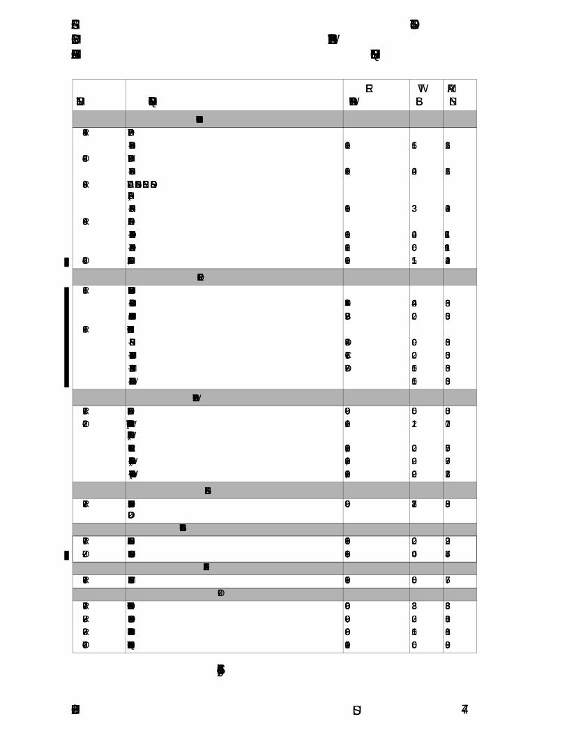
CESSNA SECTION 4MODEL 162 WEIGHT AND BALANCE/GARMIN G300 EQUIPMENT LIST
U.S.
Figure 4-1 (Sheet 3)
ITEM NO EQUIPMENT LIST DESCRIPTIONREF
DRAWINGWT LBS
ARM INS.
34 - NAVIGATION34-01-R PFD DISPLAY
- GDU 370 DISPLAY 0918101 1.56 121.5634-02-O MFD DISPLAY
- GDU 375 DISPLAY 0918502 2.40 121.5634-03-R ATTITUDE HEADING REFERENCE SENSOR
(ADAHRS)- GSU 73 ADAHRS 0918109 3.33 104.32
34-04-R TRANSPONDER- GTX-327 TRANSPONDER 0918101 2.40 118.76- TRANSPONDER ANTENNA 0918122 0.06 116.91
34-05-O COMPASS, MAGNETIC 0918509 1.15 124.94
61 - PROPELLER61-01-R FIXED PITCH PROPELLER ASSEMBLY
- MCCAULEY 67 INCH PROPELLER 1A162/TCD6754 24.40 65.03- MCCAULEY 3.115 INCH PROPELLER SPACER B-7925 2.00 65.03
61-02-R SPINNER INSTALLATION, PROPELLER- SPINNER SHELL D-7945 0.90 65.03- SPINNER FRONT SUPPORT ASSEMBLY C-7961 0.20 65.03- SPINNER BULKHEAD ASSEMBLY D-7962 1.05 65.03- MOUNTING HARDWARE 1.50 65.03
71 - POWERPLANT71-01-R FILTER, INDUCTION AIR 0950000 0.50 83.0071-02-O WINTERIZATION KIT INSTALLATION (STOWED)
(INSTALLED ARM SHOWN)0901260 1.12 70.71
- BREATHER TUBE INSULATION 0901250-5, -10 0.20 75.06- COWL INLET COVERS (INSTALLED) 0901250-1, -2 0.92 69.77- COWL INLET COVERS (STOWED) 0901250-1, -2 0.92 176.21
72 - ENGINES72-01-R ENGINE, TELEDYNE CONTINENTAL MOTORS
O-200D0950000 213.78 83.95
77 - ENGINE INDICATING 77-01-R ENGINE TACHOMETER SENSOR 0918003 0.02 92.2977-02-O EXHAUST THERMOCOUPLE 0918506 0.04 78.64
78 - EXHAUST78-01-R EXHAUST SYSTEM 9950100 8.00 77.67
79 - OIL79-01-R OIL COOLER INSTALLATION 0950000 3.83 83.3679-02-R OIL PRESSURE SENSOR - P165-5281 0950000 0.32 80.8179-03-R OIL TEMPERATURE SENSOR - S2335-1 0950000 0.15 80.8179-04-O OIL QUICK DRAIN INSTALLATION 0901240 0.06 90.08
162PHUS-01 4-7

SECTION 4 CESSNAWEIGHT AND BALANCE/ MODEL 162EQUIPMENT LIST GARMIN G300
U.S.
AIRPLANE WEIGHING PROCEDURES1. Preparation:
a. Inflate tires to recommended operating pressures.b. Defuel airplane. Refer to the Maintenance Manual.c. Service engine oil as required to obtain a normal full
indication (approximately 5 quarts on dipstick).d. Raise flaps to the fully retracted position.e. Place all control surfaces in neutral position.f. Remove all non-required items from airplane.
2. Level:a. Place scales under each wheel (minimum scale capacity,
1000 pounds).b. Deflate the nose tire to properly center the bubble in the
level (Refer to Figure 4-2).3. Weigh:
a. Weigh airplane in a closed hangar to avoid errors caused byair currents.
b. With the airplane level and brakes released, record theweight shown on each scale. Deduct the tare, if any, fromeach reading.
4. Measure:a. Obtain measurement A by measuring horizontally (along the
airplane centerline) from a line stretched between the mainwheel centers to a plumb bob dropped from the firewall.
b. Obtain measurement B by measuring horizontally andparallel to the airplane centerline, from center of nosewheelaxle, left side, to a plumb bob dropped from the line betweenthe main wheel centers. Repeat on right side and averagethe measurements.
5. Using weights from step 3 and measurements from step 4, theBasic Empty Weight and C.G. can be determined by completingFigure 4-2 (Sheet 3 or Sheet 4).
6. Changes to the Airplane Weight and Balance due to alteration orrepair must be documented in a permanent record within thePOH similar to that shown in Figure 4-3.
7. A new Basic Empty Weight and CG Arm based on actualairplane weight (as weighed) is required after a major repair oralteration. It is recommended that the airplane be weighed toverify Basic Empty Weight and CG Arm at intervals not toexceed 5 years.
162PHUS-004-8
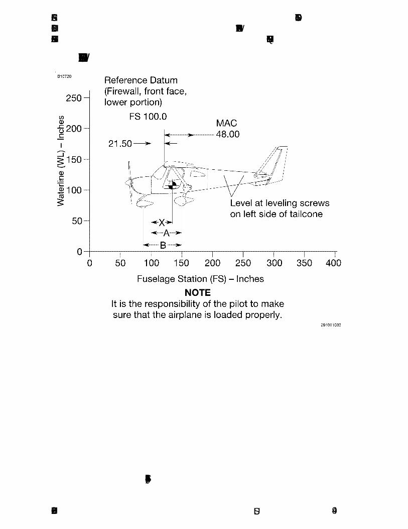
CESSNA SECTION 4MODEL 162 WEIGHT AND BALANCE/GARMIN G300 EQUIPMENT LIST
U.S.
AIRPLANE WEIGHING FORM - U.S. UNITS
Figure 4-2* (Sheet 1 of 4)
162PHUS-01 4-9

SECTION 4 CESSNAWEIGHT AND BALANCE/ MODEL 162EQUIPMENT LIST GARMIN G300
U.S.
AIRPLANE WEIGHING FORM - METRIC UNITS
Figure 4-2* (Sheet 2)
162PHUS-014-10

CESSNA SECTION 4MODEL 162 WEIGHT AND BALANCE/GARMIN G300 EQUIPMENT LIST
U.S.
AIRPLANE WEIGHING FORM - U.S. UNITS
Figure 4-2 (Sheet 3)
162PHUS-00 4-11
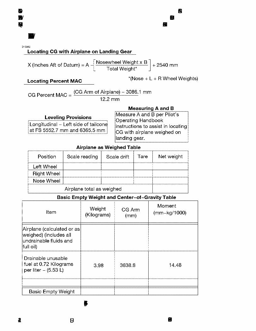
SECTION 4 CESSNAWEIGHT AND BALANCE/ MODEL 162EQUIPMENT LIST GARMIN G300
U.S.
AIRPLANE WEIGHING FORM - METRIC UNITS
Figure 4-2 (Sheet 4)
162PHUS-004-12

CESSNA SECTION 4MODEL 162 WEIGHT AND BALANCE/GARMIN G300 EQUIPMENT LIST
U.S.
SAMPLE WEIGHT AND BALANCE RECORD - U.S.
Figure 4-3 (Sheet 1 of 2)
162PHUS-00 4-13

SECTION 4 CESSNAWEIGHT AND BALANCE/ MODEL 162EQUIPMENT LIST GARMIN G300
U.S.
SAMPLE WEIGHT AND BALANCE RECORD - METRIC
Figure 4-3 (Sheet 2)
162PHUS-004-14

CESSNA SECTION 4MODEL 162 WEIGHT AND BALANCE/GARMIN G300 EQUIPMENT LIST
U.S.
WEIGHT AND BALANCE
The following information will enable you to operate your Cessna withinthe prescribed weight and center of gravity limitations. To determineweight and balance, use the Sample Loading Problem (Figure 4-4),Loading Graph (Figure 4-5), and Center of Gravity Moment Envelope(Figure 4-8) as follows:
Enter the appropriate basic empty weight and moment/1000 from theweight and balance records for your airplane in the YOUR AIRPLANEcolumn of the Sample Loading Problem.
NOTE
In addition to the basic empty weight and moment noted onthese records, the C.G. arm (FS) is also shown, but neednot be used on the Sample Loading Problem. The momentwhich is shown must be divided by 1000 and this valueused as the moment/1000 on the loading problem.
Use the Loading Graph to determine the moment/1000 for eachadditional item to be carried; then list these on the loading problem.
NOTE
Loading Graph information for the pilot, passenger andbaggage is based on baggage loaded in the center of thebaggage areas as shown on the Loading Arrangementsdiagram. For loadings which may differ from these, theSample Loading Problem lists fuselage stations (FS) forthese items to indicate their forward and aft C.G. rangelimitations (baggage area limitation). Refer to Figures 4-6and 4-7 for additional loading information. Additionalmoment calculations, based on the actual weight and C.G.arm (FS) of the item being loaded, must be made if theposition of the load is different from that shown on theLoading Graph.
Total the weights and moments/1000 and plot these values on theCenter of Gravity Moment Envelope to determine whether the pointfalls within the envelope, and if the loading is acceptable.
(Continued Next Page)
162PHUS-01 4-15

SECTION 4 CESSNAWEIGHT AND BALANCE/ MODEL 162EQUIPMENT LIST GARMIN G300
U.S.
WEIGHT AND BALANCE (Continued)
BAGGAGE TIEDOWN
A nylon baggage net, having four tiedown straps, is provided asstandard equipment to secure baggage on the cabin floor. Six eyeboltsserve as attaching points for the net. A placard located on the right sideof the baggage compartment, below the window, defines the weightlimitations in the baggage areas.
NOTE
Maximum weight in the baggage compartment area is 50pounds (22.68 kg) with a maximum floor loading of 8pounds per square foot (39.05 kilograms per square meter).
162PHUS-014-16
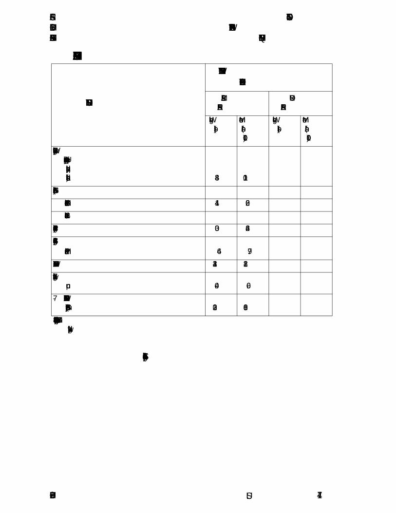
CESSNA SECTION 4MODEL 162 WEIGHT AND BALANCE/GARMIN G300 EQUIPMENT LIST
U.S.
SAMPLE LOADING PROBLEM - U.S. UNITS
ITEM DESCRIPTION
WEIGHT AND MOMENT TABULATION
SAMPLE AIRPLANE
YOUR AIRPLANE
Weight (lbs)
Moment (lb-ins/1000)
Weight (lbs)
Moment (lb-ins/1000)
1 - Basic Empty Weight(Use the data pertaining to your airplane as it is presently equipped. Includes unusable fuel and full oil) 834 110.1
2 - Usable Fuel (At 6 Lbs./Gal.)
- Standard Fuel - 24 Gallons Maximum 144 20.6
- Reduced Fuel - 12 Gallons
3 - Pilot and Front Passenger (FS 142) 300 42.6
4 - Baggage (FS 155 to 190) 50 Pounds Maximum 46 7.9
5 - RAMP WEIGHT AND MOMENT 1324 181.2
6 - Fuel allowance for engine start, taxi and runup -4.0 -0.6
7 - TAKEOFF WEIGHT AND MOMENT (Subtract Step 8 from Step 7) 1320 180.6
8 - Locate this point (1320 at 180.6) on the Center of Gravity Moment Envelope,and since this point falls within the envelope, the loading is acceptable.
Figure 4-4 (Sheet 1 of 4)
162PHUS-00 4-17
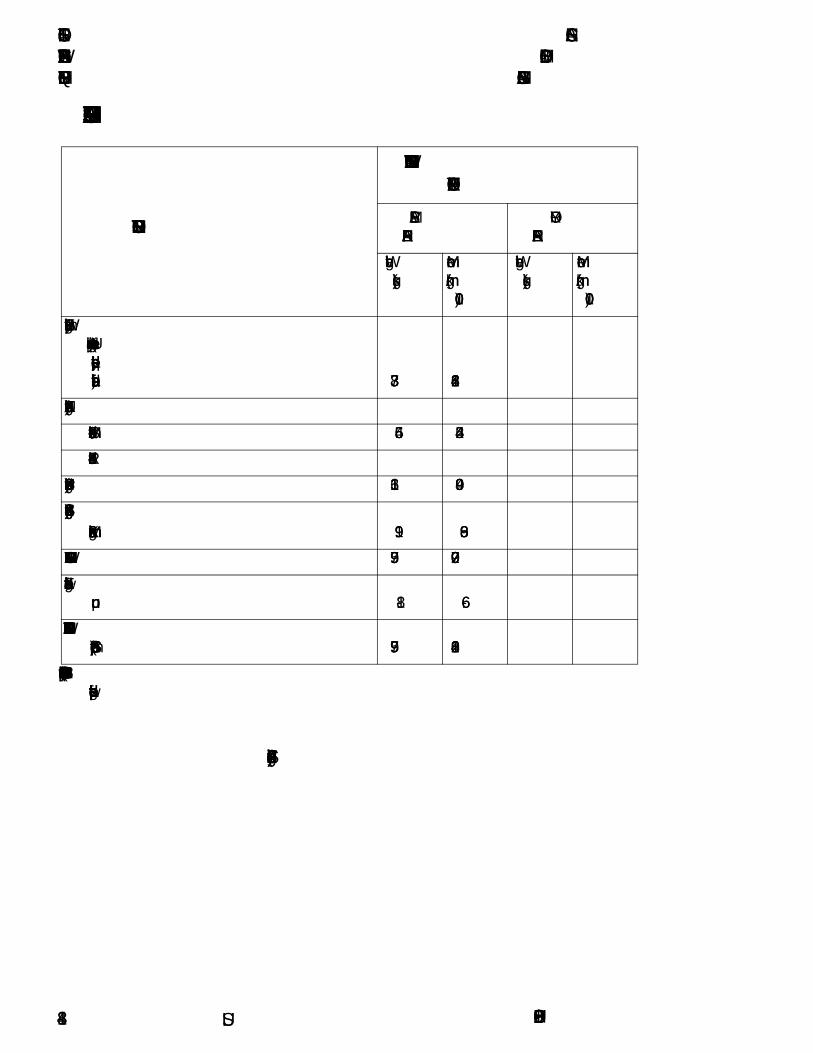
SECTION 4 CESSNAWEIGHT AND BALANCE/ MODEL 162EQUIPMENT LIST GARMIN G300
U.S.
SAMPLE LOADING PROBLEM - METRIC UNITS
Figure 4-4 (Sheet 2)
ITEM DESCRIPTION
WEIGHT AND MOMENT TABULATION
SAMPLE AIRPLANE
YOUR AIRPLANE
Weight (kgs)
Moment (kg-mm/1000)
Weight (kgs)
Moment (kg-mm/1000)
1 - Basic Empty Weight(Use the data pertaining to your airplane as it is presently equipped. Includes unusable fuel and full oil) 378.3 1268.4
2 - Usable Fuel (At 0.72 Kg./Liter)
- Standard Fuel - 90.82 Liters Maximum 65.4 244.5
- Reduced Fuel - 45.41 Liters
3 - Pilot and Front Passenger (FS 3607) 136.1 490.9
4 - Baggage (FS 3937 to 4826) 22.6 Kilograms Maximum 19.9 86.9
5 - RAMP WEIGHT AND MOMENT 599.7 2090.7
6 - Fuel allowance for engine start, taxi and runup -1.8 -6.6
7 - TAKEOFF WEIGHT AND MOMENT (Subtract Step 8 from Step 7) 597.9 2084.1
8 - Locate this point (597.9 at 2084.1) on the Center of Gravity Moment Envelope,and since this point falls within the envelope, the loading is acceptable.
162PHUS-004-18

CESSNA SECTION 4MODEL 162 WEIGHT AND BALANCE/GARMIN G300 EQUIPMENT LIST
U.S.
SAMPLE LOADING PROBLEM - U.S. UNITS
NOTE
When several loading configurations are representative ofyour operations, it may be useful to fill out one or more ofthe above columns so specific loadings are available at aglance.
Figure 4-4 (Sheet 3)
162PHUS-00 4-19

SECTION 4 CESSNAWEIGHT AND BALANCE/ MODEL 162EQUIPMENT LIST GARMIN G300
U.S.
SAMPLE LOADING PROBLEM - METRIC UNITS
NOTE
When several loading configurations are representative ofyour operations, it may be useful to fill out one or more ofthe above columns so specific loadings are available at aglance.
Figure 4-4 (Sheet 4)
YOUR AIRPLANE
YOUR AIRPLANE
YOUR AIRPLANE
Weight
(Kgs)
Moment
(Kgs-mm/1000)
Weight
(Kgs)
Moment
(Kgs-mm/1000)
Weight
(Kgs)
Moment
(Kgs-mm/1000)
162PHUS-004-20

CESSNA SECTION 4MODEL 162 WEIGHT AND BALANCE/GARMIN G300 EQUIPMENT LIST
U.S.
LOADING GRAPH - U.S. UNITS
Figure 4-5 (Sheet 1 of 2)
162PHUS-00 4-21

SECTION 4 CESSNAWEIGHT AND BALANCE/ MODEL 162EQUIPMENT LIST GARMIN G300
U.S.
LOADING GRAPH - METRIC UNITS
Figure 4-5 (Sheet 2)
162PHUS-004-22

CESSNA SECTION 4MODEL 162 WEIGHT AND BALANCE/GARMIN G300 EQUIPMENT LIST
U.S.
LOADING ARRANGEMENTS - U.S. UNITS
*Pilot and front seat passenger center of gravity for averageoccupant.
**Arm measured to the center of the areas shown.
NOTE
• All dimensions shown are in inches.
• The usable fuel C.G. arm is located at FS 143.26.
• The aft baggage wall (approximate FS 190.00) can beused as a convenient interior reference point fordetermining the location of baggage area fuselagestations.
Figure 4-6* (Sheet 1 of 2)
162PHUS-01 4-23

SECTION 4 CESSNAWEIGHT AND BALANCE/ MODEL 162EQUIPMENT LIST GARMIN G300
U.S.
LOADING ARRANGEMENTS - METRIC UNITS
*Pilot and front seat passenger center of gravity for averageoccupant.
**Arm measured to the center of the areas shown.
NOTE
• All dimensions shown are in millimeters.
• The usable fuel C.G. arm is located at FS 3638.80.
• The aft baggage wall (approximate FS 4826) can beused as a convenient interior reference point fordetermining the location of baggage area fuselagestations.
Figure 4-6* (Sheet 2)
162PHUS-014-24
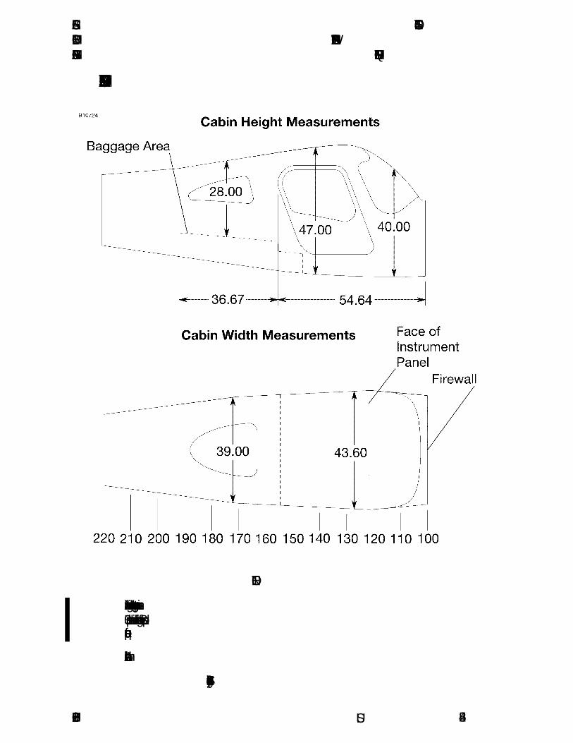
CESSNA SECTION 4MODEL 162 WEIGHT AND BALANCE/GARMIN G300 EQUIPMENT LIST
U.S.
INTERNAL CABIN DIMENSIONS - U.S. UNITS
NOTE
• Maximum weight in the baggage compartment area is50 pounds with a maximum floor loading of 8 poundsper square foot.
• All dimensions shown are in inches.
Figure 4-7 (Sheet 1 of 2)
162PHUS-01 4-25

SECTION 4 CESSNAWEIGHT AND BALANCE/ MODEL 162EQUIPMENT LIST GARMIN G300
U.S.
INTERNAL CABIN DIMENSIONS - METRIC UNITS
NOTE
• Maximum weight in the baggage compartment area is22.68 kilograms with a maximum floor loading of 39.05kilograms per square meter.
• All dimensions shown are in millimeters.
Figure 4-7 (Sheet 2)
162PHUS-014-26

CESSNA SECTION 4MODEL 162 WEIGHT AND BALANCE/GARMIN G300 EQUIPMENT LIST
U.S.
CENTER OF GRAVITY MOMENT ENVELOPE - U.S.
Figure 4-8 (Sheet 1 of 2)
162PHUS-00 4-27
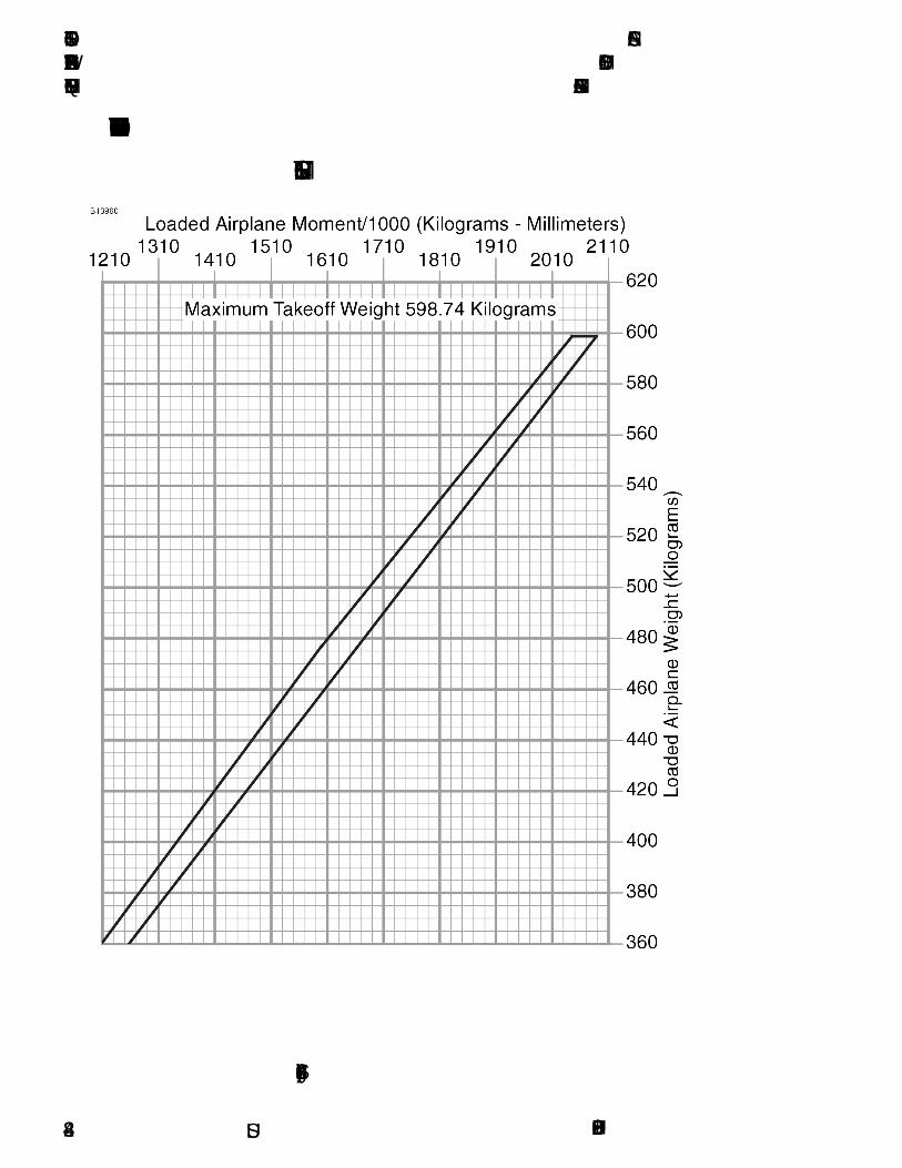
SECTION 4 CESSNAWEIGHT AND BALANCE/ MODEL 162EQUIPMENT LIST GARMIN G300
U.S.
CENTER OF GRAVITY MOMENT ENVELOPE
METRIC UNITS
Figure 4-8 (Sheet 2)
162PHUS-004-28

CESSNA SECTION 4MODEL 162 WEIGHT AND BALANCE/GARMIN G300 EQUIPMENT LIST
U.S.
CENTER OF GRAVITY LIMITS - U.S. UNITS
Figure 4-9 (Sheet 1 of 2)
162PHUS-00 4-29
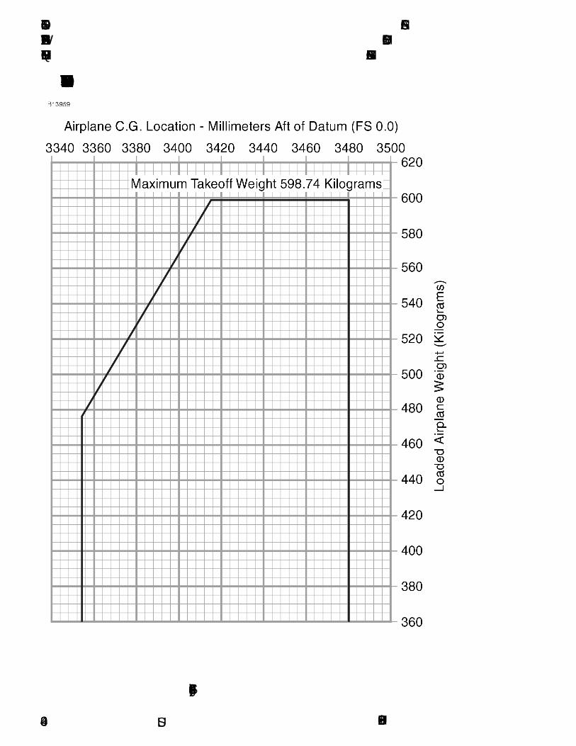
SECTION 4 CESSNAWEIGHT AND BALANCE/ MODEL 162EQUIPMENT LIST GARMIN G300
U.S.
CENTER OF GRAVITY LIMITS - METRIC UNITS
Figure 4-9 (Sheet 2)
162PHUS-004-30

CESSNA SECTION 5MODEL 162 PERFORMANCEGARMIN G300
PERFORMANCE
TABLE OF CONTENTSPage
Introduction . . . . . . . . . . . . . . . . . . . . . . . . . . . . . . . . . . . . . . . . . . . .5-3Use of Performance Charts . . . . . . . . . . . . . . . . . . . . . . . . . . . . . . . .5-3Sample Problem . . . . . . . . . . . . . . . . . . . . . . . . . . . . . . . . . . . . . . . .5-4
Takeoff. . . . . . . . . . . . . . . . . . . . . . . . . . . . . . . . . . . . . . . . . . . . . .5-5Cruise . . . . . . . . . . . . . . . . . . . . . . . . . . . . . . . . . . . . . . . . . . . . . .5-6Fuel Required . . . . . . . . . . . . . . . . . . . . . . . . . . . . . . . . . . . . . . . .5-7Landing . . . . . . . . . . . . . . . . . . . . . . . . . . . . . . . . . . . . . . . . . . . . .5-9
Demonstrated Operating Temperature . . . . . . . . . . . . . . . . . . . . . . .5-9Airspeed Calibration . . . . . . . . . . . . . . . . . . . . . . . . . . . . . . . . . . . .5-10Stall Speeds At 1320 Pounds . . . . . . . . . . . . . . . . . . . . . . . . . . . . . 5-11Short Field Takeoff Distance At 1320 Pounds . . . . . . . . . . . . . . . . .5-12Short Field Landing Distance At 1320 Pounds . . . . . . . . . . . . . . . .5-13Maximum Rate Of Climb At 1320 Pounds . . . . . . . . . . . . . . . . . . . .5-14Time, Fuel And Distance To Climb At 1320 Pounds . . . . . . . . . . . .5-15Cruise Performance. . . . . . . . . . . . . . . . . . . . . . . . . . . . . . . . . . . . .5-16Temperature Conversion Chart . . . . . . . . . . . . . . . . . . . . . . . . . . . .5-17Crosswind Component . . . . . . . . . . . . . . . . . . . . . . . . . . . . . . . . . .5-18
U.S.162PHUS-00 5-1/5-2


CESSNA SECTION 5MODEL 162 PERFORMANCEGARMIN G300
U.S.
INTRODUCTION
Performance data charts on the following pages are presented so thatyou may know what to expect from the airplane under variousconditions and to facilitate the planning of flights in detail withreasonable accuracy. The data in the charts has been computed fromactual flight tests with the airplane and engine in good condition andusing average piloting techniques.
Fuel flow data for cruise is based on the recommended lean mixturesetting at all altitudes. Some indeterminate variables such as mixtureleaning technique, fuel metering characteristics, engine and propellercondition, and air turbulence may account for variations of 10% or morein range and endurance. Therefore, it is important to utilize all availableinformation to estimate the fuel required for the particular flight and toflight plan in a conservative manner.
USE OF PERFORMANCE CHARTS
Performance data is presented in tabular form to illustrate the effect ofdifferent variables. Sufficiently detailed information is provided in thetables so that conservative values can be selected and used todetermine the particular performance figure with reasonable accuracy.
162PHUS-01 5-3

SECTION 5 CESSNAPERFORMANCE MODEL 162
GARMIN G300
U.S.
SAMPLE PROBLEM
The following sample flight problem utilizes information from thevarious charts to determine the predicted performance data for a typicalflight. Assume the following information has already been determined:
(Continued Next Page)
AIRPLANE CONFIGURATION:Takeoff weight 1320 PoundsUsable fuel 24.0 Gallons
TAKEOFF CONDITIONS:Field pressure altitude 1500 FeetTemperature 28°C (16°C Above Standard)Wind component along runway 14 Knot Head WindField length 3500 Feet
CRUISE CONDITIONS: Total distance 260 Nautical MilesPressure altitude 5500 FeetTemperature 20°C (16°C Above Standard)Expected wind enroute 10 Knot Head Wind
LANDING CONDITIONS:Field pressure altitude 2000 FeetTemperature 25°CField length 3000 Feet
162PHUS-015-4

CESSNA SECTION 5MODEL 162 PERFORMANCEGARMIN G300
U.S.
SAMPLE PROBLEM (Continued)
TAKEOFF
The takeoff distance chart, Figure 5-3, should be consulted, keeping inmind that distances shown are based on the short field technique.Conservative distances can be established by reading the chart at thenext higher value of weight, altitude and temperature. For example, inthis particular sample problem, the takeoff distance informationpresented for a weight of 1320 pounds, pressure altitude of 2000 feetand a temperature of 30°C should be used and results in the following:
These distances are well within the available takeoff field length.However, a correction for the effect of wind may be made based oninformation presented in the note section of the takeoff chart. Thecorrection for a 14 knot head wind is:
This results in the following distances, corrected for wind:
(Continued Next Page)
Ground roll 860 Feet
Total distance to clear a 50-foot obstacle 1495 Feet
14 Knots X 10% = 20% Decrease
7 Knots
Ground roll, zero wind 860 Feet
Decrease in ground roll (860 feet X 20%) -172 Feet
Corrected ground roll 688 Feet
Total distance to clear a 50-foot obstacle, zero wind 1495 Feet
Decrease in total distance (1495 feet X 20%) -299 Feet
Corrected total distance to clear 50-foot obstacle 1196 Feet
162PHUS-01 5-5
SECTION 5 CESSNAPERFORMANCE MODEL 162
GARMIN G300
U.S.
SAMPLE PROBLEM (Continued)
CRUISE
The cruising altitude should be selected based on a consideration oftrip length, winds aloft and the airplane's performance. A typicalcruising altitude and the expected wind enroute have been given forthis sample problem. However, the power setting selection for cruisemust be determined based on several considerations. These includethe cruise performance characteristics presented in Figure 5-7, themaximum rate of climb chart presented in Figure 5-5, and the time, fueland distance to climb chart presented in Figure 5-6.
The cruise performance chart, Figure 5-7, is entered at 6000 feetpressure altitude and 20°C above standard temperature. These valuesmost nearly correspond to the planned altitude and expectedtemperature conditions. The engine speed chosen is 2750 RPM, whichresults in the following:
(Continued Next Page)
Power 64%True airspeed 108 KnotsCruise fuel flow 6.0 GPH
162PHUS-015-6
CESSNA SECTION 5MODEL 162 PERFORMANCEGARMIN G300
U.S.
SAMPLE PROBLEM (Continued)
FUEL REQUIRED
The total fuel requirement for the flight may be estimated using theperformance information in Figure 5-6 and Figure 5-7. For this sampleproblem, the time, fuel and distance to climb may be determined fromFigure 5-6 for maximum rate of climb. The difference between thevalues shown in the table for 5500 feet and 1500 feet results in thefollowing:
These values are for a standard temperature and are sufficientlyaccurate for most flight planning purposes. However, a furthercorrection for the effect of temperature may be made as noted on theclimb chart. The approximate effect of a nonstandard temperature is toincrease the time, fuel and distance by 10% for each 10°C abovestandard temperature, due to the lower rate of climb. In this case,assuming a temperature 16°C above standard the correction would be:
With this factor included, the fuel estimate would be calculated asfollows:
Using a similar procedure for the distance to climb results in 7 nauticalmiles.
The resultant cruise distance is:
(Continued Next Page)
Time: 6.5 MinutesFuel: 0.9 GallonsDistance: 6.0 Nautical Miles
16°CX 10% = 16% Increase10°C
Fuel to climb, standard temperature 0.9 GallonsIncrease due to non-standard temperature (0.9 X 16%) 0.1 GallonsCorrected fuel to climb 1.0 Gallons
Total distance 260 Nautical MilesClimb distance -7 Nautical MilesCruise distance 253 Nautical Miles
162PHUS-01 5-7

SECTION 5 CESSNAPERFORMANCE MODEL 162
GARMIN G300
U.S.
SAMPLE PROBLEM (Continued)
FUEL REQUIRED (Continued)
With an expected 10 knot head wind, the ground speed for cruise ispredicted to be:
Therefore, the time required for the cruise portion of the trip is:
The fuel required for cruise is:
A 30-minute reserve requires:
The total estimated fuel required is as follows:
Once the flight is underway, ground speed checks will provide a moreaccurate basis for estimating the time enroute and the correspondingfuel required to complete the trip with ample reserve.
(Continued Next Page)
108 Knots-10 Knots98 Knots
253 Nautical Miles = 2.6 Hours98 Knots
2.6 hours 6.0 gallons/hour = 15.6 Gallons
30 6.0 gallons/hour = 3.0 Gallons60
Engine start, taxi, and takeoff 0.6 Gallons
Climb 1.0 Gallons
Cruise 15.6 Gallons
Reserve 3.0 Gallons
Total fuel required 20.2 Gallons
162PHUS-015-8

CESSNA SECTION 5MODEL 162 PERFORMANCEGARMIN G300
U.S.
SAMPLE PROBLEM (Continued)
LANDING
A procedure similar to takeoff should be used for estimating the landingdistance at the destination airport. Figure 5-4 presents landing distanceinformation for the short field technique. The distances correspondingto 2000 feet and 30°C are as follows:
A correction for the effect of wind may be made based on informationpresented in the note section of the landing chart, using the sameprocedure as outlined for takeoff.
DEMONSTRATED OPERATING TEMPERATURE
Satisfactory engine cooling has been demonstrated for this airplanewith an outside air temperature 23°C above standard. This is not to beconsidered as an operating limitation. Reference should be made toSection 2 for engine operating limitations.
Ground roll 760 FeetTotal distance to clear a 50-foot obstacle 1485 Feet
162PHUS-01 5-9

SECTION 5 CESSNAPERFORMANCE MODEL 162
GARMIN G300
U.S.
Figure 5-1
162PHUS-005-10
CESSNA SECTION 5MODEL 162 PERFORMANCEGARMIN G300
U.S.
NOTE
• Altitude loss during a stall recovery may be as much as250 feet.
• KIAS values are approximate.
Figure 5-2
162PHUS-00 5-11

SECTION 5 CESSNAPERFORMANCE MODEL 162
GARMIN G300
U.S.
Figure 5-3*
162PHUS-015-12
CESSNA SECTION 5MODEL 162 PERFORMANCEGARMIN G300
U.S.
Figure 5-4*
5-13162PHUS-01

SECTION 5 CESSNAPERFORMANCE MODEL 162
GARMIN G300
U.S.
Figure 5-5*
162PHUS-015-14
CESSNA SECTION 5MODEL 162 PERFORMANCEGARMIN G300
U.S.
Figure 5-6*
162PHUS-01 5-15

SECTION 5 CESSNAPERFORMANCE MODEL 162
GARMIN G300
U.S.
Figure 5-7*
162PHUS-015-16

CESSNA SECTION 5MODEL 162 PERFORMANCEGARMIN G300
U.S.
TEMPERATURE CONVERSION CHART
Figure 5-8
162PHUS-00 5-17

SECTION 5 CESSNAPERFORMANCE MODEL 162
GARMIN G300
U.S.
CROSSWIND COMPONENT
NOTE
Maximum demonstrated crosswind velocity is 12 knots (nota limitation).
Figure 5-9
162PHUS-005-18

CESSNA SECTION 6MODEL 162 EMERGENCY PROCEDURESGARMIN G300
EMERGENCY PROCEDURES
TABLE OF CONTENTS
Page
Introduction . . . . . . . . . . . . . . . . . . . . . . . . . . . . . . . . . . . . . . . . . . . .6-5
Airspeeds For Emergency Operations. . . . . . . . . . . . . . . . . . . . . . . .6-5
EMERGENCY PROCEDURES . . . . . . . . . . . . . . . . . . . . . . . . .6-6
ENGINE FAILURES AND MALFUNCTIONS . . . . . . . . . . . . . . . . . .6-6Engine Failure During Takeoff Roll . . . . . . . . . . . . . . . . . . . . . . . .6-6Engine Failure Immediately After Takeoff . . . . . . . . . . . . . . . . . . .6-6Engine Failure During Flight (Restart Procedures) . . . . . . . . . . . .6-7Oil PSI Indicator In Red Band Range (Red Digits) . . . . . . . . . . . .6-7Carb °F Indicator In Yellow Band Range (Yellow Digits) . . . . . . . .6-8
FORCED LANDINGS . . . . . . . . . . . . . . . . . . . . . . . . . . . . . . . . . . . .6-9Emergency Landing Without Engine Power . . . . . . . . . . . . . . . . .6-9Precautionary Landing With Engine Power. . . . . . . . . . . . . . . . .6-10Ditching . . . . . . . . . . . . . . . . . . . . . . . . . . . . . . . . . . . . . . . . . . . . 6-11
FIRES . . . . . . . . . . . . . . . . . . . . . . . . . . . . . . . . . . . . . . . . . . . . . . .6-12During Start On Ground . . . . . . . . . . . . . . . . . . . . . . . . . . . . . . .6-12Engine Fire In Flight . . . . . . . . . . . . . . . . . . . . . . . . . . . . . . . . . .6-12Electrical Fire or Cabin Fire In Flight. . . . . . . . . . . . . . . . . . . . . .6-13Wing Fire. . . . . . . . . . . . . . . . . . . . . . . . . . . . . . . . . . . . . . . . . . .6-14
ICING. . . . . . . . . . . . . . . . . . . . . . . . . . . . . . . . . . . . . . . . . . . . . . . .6-15Inadvertent Icing Encounter During Flight. . . . . . . . . . . . . . . . . .6-15
ABNORMAL LANDINGS . . . . . . . . . . . . . . . . . . . . . . . . . . . . . . . .6-17Landing With Partial or No Flight Instrument Information . . . . . .6-17Landing With A Flat Main Tire . . . . . . . . . . . . . . . . . . . . . . . . . . .6-17Landing With A Flat Nose Tire . . . . . . . . . . . . . . . . . . . . . . . . . .6-18Door Open in Flight . . . . . . . . . . . . . . . . . . . . . . . . . . . . . . . . . . .6-18Landing With Door Open. . . . . . . . . . . . . . . . . . . . . . . . . . . . . . .6-18
(Continued Next Page)
U.S.162PHUS-00 6-1

SECTION 6 CESSNAEMERGENCY PROCEDURES MODEL 162
GARMIN G300
U.S.
TABLE OF CONTENTS (Continued)Page
ELECTRICAL POWER SUPPLY SYSTEM MALFUNCTIONS . . . 6-19Loss Of All Electrical Power (Except PFD) . . . . . . . . . . . . . . . . 6-19LOW VOLTS Annunciator Comes On or Volts Indication Below
Green Band Range or Volts Less Than 12.5. . . . . . . . . . . . . . 6-20Volts Indication Above Green Band Range or Volts More Than 15 . . . . . . . . . . . . . . . . . . . . . . . . . . . . . . . . 6-22
AIR DATA, ATTITUDE AND HEADING REFERENCE SYSTEM (ADAHRS) FAILURE . . . . . . . . . . . . . . . . . . . . . . . . . . . . . . . . . . . 6-23
Red X - PFD or MFD Indicators (Airspeed, Altitude, Attitude, Horizontal Situation Indicator (HSI), or Engine Indicating System (EIS)) . . . . . . . . . . . . . . . . . . . . . . . . . . . . . . . . . . . . . 6-23
PFD/MFD DISPLAY MALFUNCTION OR FAILURE . . . . . . . . . . . 6-24PFD or MFD Display Black (No Information) . . . . . . . . . . . . . . . 6-24PFD or MFD Display Information Not Updating. . . . . . . . . . . . . 6-25
Electric Pitch Trim Failure. . . . . . . . . . . . . . . . . . . . . . . . . . . . . . . . 6-26
(Continued Next Page)
162PHUS-006-2

CESSNA SECTION 6MODEL 162 EMERGENCY PROCEDURESGARMIN G300
U.S.
TABLE OF CONTENTS (Continued)
Page
AMPLIFIED EMERGENCY PROCEDURES . . . . . . . . . . . . . . . . . .6-27Engine Failure . . . . . . . . . . . . . . . . . . . . . . . . . . . . . . . . . . . . . . . . .6-27Maximum Glide . . . . . . . . . . . . . . . . . . . . . . . . . . . . . . . . . . . . . . . .6-28Forced Landings . . . . . . . . . . . . . . . . . . . . . . . . . . . . . . . . . . . . . . .6-29Landing Without Elevator Control . . . . . . . . . . . . . . . . . . . . . . . . . .6-30Fires. . . . . . . . . . . . . . . . . . . . . . . . . . . . . . . . . . . . . . . . . . . . . . . . .6-30Emergency Operation In Clouds . . . . . . . . . . . . . . . . . . . . . . . . . . .6-31
Executing A 180° Turn In Clouds (ADAHRS FAILED) . . . . . . . .6-31Emergency Descent Through Clouds (ADAHRS FAILED) . . . . .6-32Recovery From Spiral Dive In The Clouds (ADAHRS FAILED) .6-33
Inadvertent Flight Into Icing Conditions . . . . . . . . . . . . . . . . . . . . . .6-34Spins . . . . . . . . . . . . . . . . . . . . . . . . . . . . . . . . . . . . . . . . . . . . . . . .6-35Rough Engine Operation Or Loss Of Power . . . . . . . . . . . . . . . . . .6-36
Carburetor Icing . . . . . . . . . . . . . . . . . . . . . . . . . . . . . . . . . . . . .6-36Spark Plug Fouling . . . . . . . . . . . . . . . . . . . . . . . . . . . . . . . . . . .6-36Magneto Malfunction. . . . . . . . . . . . . . . . . . . . . . . . . . . . . . . . . .6-36Idle Power Engine Roughness . . . . . . . . . . . . . . . . . . . . . . . . . .6-37Low Oil Pressure. . . . . . . . . . . . . . . . . . . . . . . . . . . . . . . . . . . . .6-37
Electrical Power Supply System Malfunctions. . . . . . . . . . . . . . . . .6-38Excessive Rate Of Charge . . . . . . . . . . . . . . . . . . . . . . . . . . . . .6-38Insufficient Rate Of Charge. . . . . . . . . . . . . . . . . . . . . . . . . . . . .6-39
Other Emergencies . . . . . . . . . . . . . . . . . . . . . . . . . . . . . . . . . . . . .6-40Windshield Damage . . . . . . . . . . . . . . . . . . . . . . . . . . . . . . . . . .6-40G300 Failures . . . . . . . . . . . . . . . . . . . . . . . . . . . . . . . . . . . . . . .6-40
162PHUS-00 6-3/6-4

CESSNA SECTION 6MODEL 162 EMERGENCY PROCEDURESGARMIN G300
INTRODUCTION
Section 6 provides checklist and amplified procedures for coping withemergencies that may occur. Emergencies caused by airplane orengine malfunctions are extremely rare if proper preflight inspectionsand maintenance are practiced. Enroute weather emergencies can beminimized or eliminated by careful flight planning and good judgmentwhen unexpected weather is encountered. However, should anemergency arise, the basic guidelines described in this section shouldbe considered and applied as necessary to correct the problem. In anyemergency situation, the most important task is continued control of theairplane and maneuver to execute a successful landing.
Emergency procedures associated with optional or supplementalequipment are found in Section 10, Supplements.
AIRSPEEDS FOR EMERGENCY OPERATIONS
ENGINE FAILURE AFTER TAKEOFFWing Flaps UP . . . . . . . . . . . . . . . . . . . . . . . . . . . . . . . . . . .70 KIASWing Flaps 10° - FULL . . . . . . . . . . . . . . . . . . . . . . . . . . . . .65 KIAS
OPERATING MANEUVERING SPEED1320 POUNDS . . . . . . . . . . . . . . . . . . . . . . . . . . . . . . . . . . .89 KIAS1200 POUNDS . . . . . . . . . . . . . . . . . . . . . . . . . . . . . . . . . . .85 KIAS1100 POUNDS . . . . . . . . . . . . . . . . . . . . . . . . . . . . . . . . . . .80 KIAS
MAXIMUM GLIDE . . . . . . . . . . . . . . . . . . . . . . . . . . . . . . . . . . .70 KIAS
PRECAUTIONARY LANDING WITH ENGINE POWER . . . . . .60 KIAS
LANDING WITHOUT ENGINE POWERWing Flaps UP . . . . . . . . . . . . . . . . . . . . . . . . . . . . . . . . . . .70 KIASWing Flaps 10° - FULL . . . . . . . . . . . . . . . . . . . . . . . . . . . . .65 KIAS
U.S.162PHUS-02 6-5

SECTION 6 CESSNAEMERGENCY PROCEDURES MODEL 162
GARMIN G300
U.S.
EMERGENCY PROCEDURES
Procedures in the Emergency Procedures Checklist portion of thissection shown in bold faced type are immediate action items whichshould be committed to memory.
ENGINE FAILURES AND MALFUNCTIONS
ENGINE FAILURE DURING TAKEOFF ROLL1. THROTTLE Control - IDLE (pull full out)2. Brakes - APPLY3. Wing Flaps - RETRACT4. MIXTURE Control - IDLE CUTOFF (pull full out)5. MAGNETOS Switch - OFF6. MASTER Switch (ALT and BAT) - OFF
ENGINE FAILURE IMMEDIATELY AFTER TAKEOFF1. Airspeed - 70 KIAS - Flaps UP
65 KIAS - Flaps 10° - FULL2. MIXTURE Control - IDLE CUTOFF (pull full out)3. FUEL SHUTOFF Valve - OFF (pull full out)4. MAGNETOS Switch - OFF5. Wing Flaps - AS REQUIRED (FULL recommended)6. MASTER Switch (ALT and BAT) - OFF (when landing is
assured)7. Land - STRAIGHT AHEAD8. Doors - UNLATCH (just prior to touchdown)
NOTE
Both cabin doors are equipped with gas struts and shouldopen automatically when unlatched. Delaying opening untiljust prior to touchdown will reduce cabin buffeting and windnoise. Non-emergency flight with doors open is prohibited.
(Continued Next Page)
162PHUS-006-6
CESSNA SECTION 6MODEL 162 EMERGENCY PROCEDURESGARMIN G300
U.S.
ENGINE FAILURES AND MALFUNCTIONS (Continued)
ENGINE FAILURE DURING FLIGHT (Restart Procedures)1. Airspeed - 70 KIAS (best glide speed)2. THROTTLE Control - IDLE (pull full out)3. CARB HEAT Control Knob - ON (pull full out)4. FUEL SHUTOFF Valve - ON (push full in)5. MIXTURE Control - RICH (if restart has not occurred)6. PRIMER - IN and LOCKED (if installed)7. MAGNETOS Switch - BOTH (or START if propeller is stopped)
NOTE
If the propeller is windmilling, engine will restartautomatically within a few seconds. If propeller has stopped(possible at low speeds), turn MAGNETOS switch toSTART, advance throttle slowly from idle and lean themixture from full rich as required to obtain smoothoperation.
OIL PSI INDICATOR IN RED BAND RANGE (RED DIGITS)1. OIL °F - CHECK
IF OIL °F ABOVE GREEN BAND RANGE OR OIL °F RISING(engine failure immanent)2. Throttle Control - REDUCE POWER IMMEDIATELY3. Airspeed - 70 KIAS (best glide speed)4. Land as soon as possible (refer to EMERGENCY LANDING
WITHOUT ENGINE POWER)
IF OIL °F WITHIN GREEN BAND RANGE2. OIL °F - MONITOR3. OIL PSI - MONITOR4. Land as soon as practical (nearest suitable airport
recommended)
(Continued Next Page)
162PHUS-01 6-7

SECTION 6 CESSNAEMERGENCY PROCEDURES MODEL 162
GARMIN G300
U.S.
ENGINE FAILURES AND MALFUNCTIONS (Continued)
CARB °F INDICATOR IN YELLOW BAND RANGE(YELLOW DIGITS)
1. ENGINE - MONITOR FOR ROUGHNESS AND/OR RPM LOSS
NOTE
Carb °F indicator in yellow band range indicatestemperatures may support carb icing formation.
IF ENGINE ROUGHNESS AND/OR RPM LOSS IS DETECTED(CARB °F IN YELLOW BAND RANGE)2. CARB HEAT Control Knob - ON (pull full out)3. THROTTLE Control - FULL (push full in)4. MIXTURE Control - LEAN (as required)5. CARB °F Indicator - CHECK
IF ENGINE ROUGHNESS CONTINUES6. CARB °F Indicator - MONITOR7. ALTITUDE - CONSIDER CHANGE (to warmer or drier air mass
if terrain permits)8. Land as soon as practical.
IF ENGINE ROUGHNESS IS NOT DETECTED (CARB °F ABOVEYELLOW BAND RANGE)6. CARB °F Indicator - MONITOR7. CARB HEAT Control Knob - AS REQUIRED8. Continue flight as normal.
162PHUS-016-8

CESSNA SECTION 6MODEL 162 EMERGENCY PROCEDURESGARMIN G300
U.S.
FORCED LANDINGS
EMERGENCY LANDING WITHOUT ENGINE POWER1. Seats and Seat Belts - SECURE2. Airspeed -70 KIAS - Flaps UP
65 KIAS - Flaps 10° - FULL3. MIXTURE Control - IDLE CUTOFF (pull full out)4. FUEL SHUTOFF Valve - OFF (pull full out)5. Radio - ALERT ATC or TRANSMIT MAYDAY ON 121.5 MHZ,
(give location, intentions and SQUAWK 7700)6. MAGNETOS Switch - OFF7. Wing Flaps - AS REQUIRED (FULL recommended)8. MASTER Switch (ALT and BAT) - OFF (when landing is
assured)9. ELT - ACTIVATE10. Doors - UNLATCH (just prior to touchdown)
NOTE
Both cabin doors are equipped with gas struts and shouldopen automatically when unlatched. Delaying opening untiljust prior to touchdown will reduce cabin buffeting and windnoise. Non-emergency flight with doors open is prohibited.
11. Touchdown - SLIGHTLY TAIL LOW12. Brakes - APPLY HEAVILY
(Continued Next Page)
162PHUS-00 6-9
SECTION 6 CESSNAEMERGENCY PROCEDURES MODEL 162
GARMIN G300
U.S.
FORCED LANDINGS (Continued)
PRECAUTIONARY LANDING WITH ENGINE POWER1. Seats and Seat Belts - SECURE2. Airspeed - 70 KIAS3. Wing Flaps - 10° or 25°4. Radio - ALERT ATC or TRANSMIT MAYDAY ON 121.5 MHZ,
(give location, intentions and SQUAWK 7700)5. Selected Field - FLY OVER (noting terrain and obstructions)6. Wing Flaps - FULL (on final approach)7. Airspeed - 60 KIAS8. MASTER Switch (ALT and BAT) - OFF (when landing assured)9. ELT - ACTIVATE10. Doors - UNLATCH (Just prior to touchdown)
NOTE
Both cabin doors are equipped with gas struts and shouldopen automatically when unlatched. Delaying opening untiljust prior to touchdown will reduce cabin buffeting and windnoise. Non-emergency flight with doors open is prohibited.
11. Touchdown - SLIGHTLY TAIL LOW12. MIXTURE Control - IDLE CUTOFF (pull full out)13. MAGNETOS Switch - OFF14. Brakes - APPLY HEAVILY
162PHUS-006-10
CESSNA SECTION 6MODEL 162 EMERGENCY PROCEDURESGARMIN G300
U.S.
FORCED LANDINGS (Continued)
DITCHING1. Radio - TRANSMIT MAYDAY on 121.5 MHz, (give location,
intentions and SQUAWK 7700)2. Heavy Objects (in baggage area) - SECURE OR JETTISON (if
possible)3. Seats and Seat Belts - SECURE4. Wing Flaps - 25° or FULL5. Power - ESTABLISH 300 FT/MIN DESCENT AT 60 KIAS
NOTE
If no power is available, approach at 70 KIAS with Flaps UPor at 65 KIAS with Flaps 10°.
6. Approach - High Winds, Heavy Seas - INTO THE WINDLight Winds, Heavy Swells - PARALLEL TOSWELLS
7. ELT - ACTIVATE8. Doors - UNLATCH (just prior to touchdown)
NOTE
Both cabin doors are equipped with gas struts and shouldopen automatically when unlatched. Delaying opening untiljust prior to touchdown will reduce cabin buffeting and windnoise. Non-emergency flight with doors open is prohibited.
9. Touchdown - LEVEL ATTITUDE AT ESTABLISHED 300 FT/MINDESCENT
10. Face - CUSHION AT TOUCHDOWN (with folded coat)11. Airplane - EVACUATE THROUGH CABIN DOORS
162PHUS-00 6-11
SECTION 6 CESSNAEMERGENCY PROCEDURES MODEL 162
GARMIN G300
U.S.
FIRES
DURING START ON GROUND1. MAGNETOS Switch - START (continue cranking to start the
engine)
IF ENGINE STARTS2. Power - 1800 RPM (for a few minutes)3. Engine - SHUTDOWN (inspect for damage)
IF ENGINE FAILS TO START2. THROTTLE Control - FULL (push full in)3. MIXTURE Control - IDLE CUTOFF (pull full out)4. MAGNETOS Switch - START (continue cranking)5. FUEL SHUTOFF Valve - OFF (pull full out)6. MAGNETOS Switch - OFF7. MASTER Switch (ALT and BAT) - OFF8. Engine - SECURE9. Parking Brake - RELEASE10. Fire Extinguisher - OBTAIN (have ground attendants obtain if not
installed)11. Airplane - EVACUATE12. Fire - EXTINGUISH (using fire extinguisher, wool blanket, or dirt)13. Fire Damage - INSPECT (repair or replace damaged
components and/or wiring before conducting another flight)
ENGINE FIRE IN FLIGHT1. MIXTURE Control - IDLE CUTOFF (pull full out)2. FUEL SHUTOFF Valve - OFF (pull full out)3. MASTER Switch (ALT Only) - OFF4. Cabin Vents - OPEN (as needed)5. CABIN HEAT Control Knob - OFF (push full in) (to avoid drafts)6. Airspeed - 85 KIAS (If fire is not extinguished, increase glide
speed to find an airspeed, within airspeed limitations, which willprovide an incombustible mixture)
7. Forced Landing - EXECUTE (refer to EMERGENCY LANDINGWITHOUT ENGINE POWER)
(Continued Next Page)
162PHUS-006-12

CESSNA SECTION 6MODEL 162 EMERGENCY PROCEDURESGARMIN G300
U.S.
FIRES (Continued)
ELECTRICAL FIRE OR CABIN FIRE IN FLIGHT1. MASTER Switch (ALT and BAT) - OFF
WARNING
OUTSIDE VISUAL REFERENCE MUST BE USED TOMAINTAIN SITUATIONAL AWARENESS. ALL FLIGHTINSTRUMENTS, RADIOS, AND PITCH TRIM WILL BEINOPERATIVE WHEN MASTER SWITCH IS TURNEDOFF.
2. Cabin Vents - CLOSED (to avoid drafts)3. CABIN HEAT Control Knob - OFF (push full in) (to avoid
drafts)4. Fire Extinguisher - ACTIVATE (if available)5. AVN MASTER Switch - OFF6. All Other Switches (except MAGNETOS switch) - OFF
IF FIRE HAS NOT BEEN EXTINGUISHED7. MASTER Switch (ALT and BAT) - ON8. Rapid Descent - EXECUTE (Perform sideslip to rapidly
loose altitude and shorten exposure time).9. AVN MASTER Switch - ON10. Radio - ALERT ATC or TRANSMIT MAYDAY ON 121.5 MHZ,
(give location, intentions and SQUAWK 7700)11. Forced Landing - EXECUTE (refer to PRECAUTIONARY
LANDING WITH ENGINE POWER)
NOTE
The G300 self-test and ADAHRS alignment may takeseveral minutes to establish thus delaying display of flightinstrument data. It may be necessary to execute landingwithout airspeed or altitude information.
(Continued Next Page)
162PHUS-00 6-13

SECTION 6 CESSNAEMERGENCY PROCEDURES MODEL 162
GARMIN G300
U.S.
FIRES (Continued)
ELECTRICAL FIRE OR CABIN FIRE IN FLIGHT (Continued)
IF FIRE HAS BEEN EXTINGUISHED AND ELECTRICAL POWERIS NECESSARY FOR CONTINUED FLIGHT TO NEARESTSUITABLE AIRPORT OR LANDING AREA
WARNING
AFTER THE FIRE EXTINGUISHER HAS BEEN USED,MAKE SURE THAT THE FIRE IS EXTINGUISHEDBEFORE EXTERIOR AIR IS USED TO REMOVE SMOKEFROM THE CABIN.
7. Cabin Vents - OPEN (when sure that fire is completelyextinguished)
8. CABIN HEAT Control Knob - ON (pull full out) (when sure that fireis completely extinguished)
9. Circuit Breakers - CHECK (for OPEN circuit(s), do not reset)10.MASTER Switch (ALT and BAT) - ON11.AVN MASTER Switch - ON12.Land the airplane as soon as possible to inspect for damage.
WING FIRE1. LDG Light Switch - OFF2. NAV Light Switch - OFF3. STROBE Light Switch - OFF
NOTE
Perform a sideslip to keep the flames away from the fueltank and cabin.
4. Land as soon as possible.
162PHUS-006-14

CESSNA SECTION 6MODEL 162 EMERGENCY PROCEDURESGARMIN G300
U.S.
ICING
INADVERTENT ICING ENCOUNTER DURING FLIGHT1. Turn back or change altitude to exit icing conditions.
Consider lateral or vertical flight path reversal to return to last"known good" flight conditions (to obtain an outside airtemperature that is less conducive to icing). Maintain VFR flight.
WARNING
FAILURE TO ACT QUICKLY MAY RESULT IN ANUNRECOVERABLE ICING ENCOUNTER.
2. CABIN HEAT Control Knob - ON (pull full out)3. A/P DISC - PRESS (if installed) ( verify autopilot disengages
and aural alert is heard)
WARNING
DO NOT ENGAGE AUTOPILOT WITH VISIBLE ICE ONAIRFRAME OR AFTER ENCOUNTERING ICINGCONDITIONS.
4. Watch for signs of induction air filter icing and apply carburetorheat as required. Monitoring the G300 Carb °F Indicator mayassist early detection. A loss of engine RPM could be caused bycarburetor ice or ice blocking the air intake filter. Adjust thethrottle as necessary to hold engine RPM. Adjust mixture asnecessary for any change in power settings or if carburetor heatis used continuously.
5. Watch for ice accretion on pitot tube and signs of pitot-staticicing. Airspeed and altimeter indications may becomeunreliable.a. Attitude and Heading information will remain reliable in
event of airspeed and altimeter failure. Use attitude indicatorto monitor pitch and bank.
b. Reference GS (ground speed) in conjunction with GPSderived wind information to determine an approximateairspeed.
(Continued Next Page)
162PHUS-01 6-15
SECTION 6 CESSNAEMERGENCY PROCEDURES MODEL 162
GARMIN G300
U.S.
ICING (Continued)
INADVERTENT ICING ENCOUNTER DURING FLIGHT(Continued)
c. Reference GPS ALTITUDE on MFD INFO page (if installed)or select G300 TERRAIN Profile page. GPS Altitude isprovided by the white arrowhead on the left side of theTERRAIN Profile display.
d. Navigate using Heading Strip, Lateral Deviation, and GPSmoving map (GPS moving map and TERRAIN Profile cannot be displayed at the same time).
NOTE
GPS information is not as accurate as barometric data butwill provide an approximate value for comparison to pitot-static instruments or a back-up if barometric instrumentsbecome unreliable.
6. Plan a landing at the nearest airport. With an extremely rapid icebuild-up, select a suitable off airport landing site.
7. With an ice accumulation of 0.25 inch (6.35mm) or more on thewing leading edges, be prepared for significantly higher powerrequirements, higher approach and stall speeds, and a longerlanding roll. Gently pitch and yaw the airplane periodically tokeep ice bridging on the controls to a minimum.
8. Leave wing flaps retracted. With a severe ice build-up on thehorizontal tail, the change in wing wake airflow direction causedby wing flap extension could result in a loss of elevatoreffectiveness.
9. Perform a landing approach using a forward slip, if necessary,for improved visibility.
10. Approach at 65 to 70 KIAS (estimated 70 KIAS. if using GPS)depending upon the amount of ice accumulation.
11. Perform landing in level attitude.12. Missed approaches should be avoided whenever possible
because of severely reduced climb capability.
162PHUS-006-16
CESSNA SECTION 6MODEL 162 EMERGENCY PROCEDURESGARMIN G300
U.S.
ABNORMAL LANDINGS
LANDING WITH PARTIAL OR NO FLIGHT INSTRUMENTINFORMATION
1. Transponder - Select Pressure Alt display using FUNC button(ADAHRS may be providing altitude information to transponder).
2. Selected Field - FLY OVER (noting terrain, obstructions, andany visual cues that may be used for speed references (i.e.traffic on nearby highway, etc))
3. Approach - NORMAL4. Wing Flaps - AS REQUIRED (FULL recommended)5. Speed - Use best pilot judgment and experience to reference
speed cues such as flap extension forces, slipstream sounds,etc. Stall warning horn will function and provide approximately 5knot stall warning.
6. Touchdown - NORMAL7. Directional Control - MAINTAIN
NOTE
Without accurate speed information, landing may be madeat faster than normal speeds. Gently apply brakes whilecontinuing to “fly” the airplane during roll-out. Loss ofdirectional control may result from locked brakes andskidding tires due to over braking.
LANDING WITH A FLAT MAIN TIRE1. Approach - NORMAL2. Wing Flaps - FULL3. Touchdown - GOOD MAIN TIRE FIRST (hold airplane off flat tire
as long as possible with aileron control)4. Directional Control - MAINTAIN (using rudder and brake on
good wheel as required)
162PHUS-01 6-17

SECTION 6 CESSNAEMERGENCY PROCEDURES MODEL 162
GARMIN G300
U.S.
ABNORMAL LANDINGS (Continued)
LANDING WITH A FLAT NOSE TIRE1. Approach - NORMAL (choose longest runway if possible)2. Wing Flaps - AS REQUIRED
a. 65 to 70 KIAS - Flaps UP - 10°b. Below 65 KIAS - Flaps 10° - FULL
3. Touchdown - ON MAINS (tail slightly low)4. Elevator - continue stick to full aft as airplane slows (hold
nosewheel off the ground as long as possible)5. When nosewheel touches down, maintain full up elevator as
airplane slows to stop.6. Directional Control - MAINTAIN (using full rudder control)
Attempt to limit differential braking. 7. Braking - Use brakes only as needed to lessen chance of prop
strike. Rolling drag of the flat nose tire will increase brakingeffect.
DOOR OPEN IN FLIGHT
WARNING
INTENTIONAL FLIGHT WITH DOOR(S) OPEN ISPROHIBITED.
1. CABIN DOOR - LEAVE OPEN (do not attempt to close)2. THROTTLE Control - REDUCE (as necessary)3. Airspeed - 80 KIAS (or less)4. Seat Belts - CHECK (verify secure and tight)5. Cabin - CHECK (stow loose materials)6. Land as soon as practical.
LANDING WITH DOOR OPEN1. Wing Flaps - AS REQUIRED
a. 65 to 70 KIAS - Flaps UP - 10°b. Below 65 KIAS - Flaps 10° - FULL
2. Landing Approach - NORMAL (limit sideslip angle if possible)3. Touchdown - NORMAL
162PHUS-016-18
CESSNA SECTION 6MODEL 162 EMERGENCY PROCEDURESGARMIN G300
U.S.
ELECTRICAL POWER SUPPLY SYSTEMMALFUNCTIONS
LOSS OF ALL ELECTRICAL POWER (EXCEPT PFD)1. MAIN CB RESET Switch - PRESS MOMENTARILY
IF ELECTRICAL POWER RESUMES NORMAL OPERATION2. Continue flight and land as soon as practical.
IF ELECTRICAL POWER REMAINS INOPERATIVE (EXCEPTPFD)2. Land as soon as possible.
NOTE
The PFD will be operating on the secondary battery only.The secondary battery is not a back-up battery. It isincluded in the electrical system to limit display presentationissues that might arise during the voltage drop whichoccurs during engine start. In good condition, thesecondary battery may provide 5 to 10 minutes of PFDoperation.
3. Prepare for total loss of electrical power and PFD. Refer toABNORMAL LANDINGS, LANDING WITH PARTIAL OR NOFLIGHT INSTRUMENT INFORMATION
(Continued Next Page)
162PHUS-00 6-19

SECTION 6 CESSNAEMERGENCY PROCEDURES MODEL 162
GARMIN G300
U.S.
ELECTRICAL POWER SUPPLY SYSTEMMALFUNCTIONS (Continued)
LOW VOLTS ANNUNCIATOR COMES ON OR VOLTSINDICATION BELOW GREEN BAND RANGE OR VOLTSLESS THAN 12.5
NOTE
Volts indication below the green band range or less than12.5 volts may occur during low RPM conditions with anelectrical load on the system such as during a low RPMtaxi. Under these conditions, the volts indication willincrease into the green band range (12.5 - 15.0 volts) athigher RPM. The master switch need not be recycled sincean overvoltage condition has not occurred to deactivate thealternator system.
1. AVN MASTER Switch - OFF
NOTE
Radio, Transponder, Pitch Trim, and options (MFD,Autopilot, and PS Intercom), if installed, will be inoperativewith AVN MASTER Switch in the OFF position.
2. START/ALT Circuit Breaker - CHECK IN (if open, reset (close)circuit breaker. If circuit breaker opens again, do not reset)
3. MASTER Switch (ALT Only) - OFF4. MASTER Switch (ALT Only) - ON5. MAIN CB RESET Switch - PRESS MOMENTARILY6. VOLTS - CHECK 13.5 Volts (minimum)7. AMPS - CHECK CHARGING (positive)8. AVN MASTER Switch - ON (only if VOLTS are 12.5 and AMPS
are charging)
162PHUS-016-20

CESSNA SECTION 6MODEL 162 EMERGENCY PROCEDURESGARMIN G300
U.S.
ELECTRICAL POWER SUPPLY SYSTEMMALFUNCTIONS (Continued)
IF VOLTS INDICATION REMAINS BELOW GREEN BAND RANGEOR LESS THAN 12.5 VOLTS9. MASTER Switch (ALT Only) - OFF10. Electrical Load - REDUCE as follows:
a. LDG Light Switch - OFF (use as required for landing)b. NAV Light Switch - OFFc. STROBE Light Switch - OFFd. AVN MASTER Switch - OFF
NOTE
Radio, Transponder, Pitch Trim, and options (MFD,Autopilot, and PS Intercom), if installed, will be inoperativewith AVN MASTER Switch in the OFF position.
11. Land as soon as practical.
NOTE
A fully charged battery in good condition should providepower under reduced load for 30 minutes.
(Continued Next Page)
162PHUS-00 6-21

SECTION 6 CESSNAEMERGENCY PROCEDURES MODEL 162
GARMIN G300
U.S.
ELECTRICAL POWER SUPPLY SYSTEMMALFUNCTIONS (Continued)
VOLTS INDICATION ABOVE GREEN BAND RANGE ORVOLTS MORE THAN 15
1. MASTER Switch (ALT Only) - OFF2. Electrical Load - REDUCE as follows:
a. LDG Light Switch - OFF (use as required for landing)b. NAV Light Switch - OFFc. STROBE Light Switch - OFFd. AVN MASTER Switch - OFF
NOTE
Radio, Transponder, Pitch Trim, and options (MFD,Autopilot, and PS Intercom), if installed, will be inoperativewith AVN MASTER - OFF.
3. Land as soon as practical.
NOTE
A fully charged battery in good condition should providepower under reduced load for 30 minutes.
162PHUS-006-22
CESSNA SECTION 6MODEL 162 EMERGENCY PROCEDURESGARMIN G300
U.S.
AIR DATA, ATTITUDE AND HEADING REFERENCESYSTEM (ADAHRS) FAILURE
RED X - PFD OR MFD INDICATORS (AIRSPEED,ALTITUDE, ATTITUDE, HORIZONTAL SITUTATIONINDICATOR (HSI), OR ENGINE INDICATING SYSTEM (EIS))
1. ADAHRS Circuit Breaker - CHECK INa. If open, reset (close) circuit breaker. If circuit breaker opens
again, do not reset.b. If closed, pull (open) ADAHRS Circuit Breaker, and pull
(open) SEC PWR Circuit Breaker (overhead Panel Light willgo off) then reset (close) both circuit breakers
2. Affected Indicator (other than EIS) - RED-X STILL DISPLAYEDa. Reference GS (ground speed) in conjunction with GPS
derived wind information to determine an approximateairspeed.
b. Select COMPASS ARC from G300 MAP SET-UP forapproximate GPS derived heading information or monitormagnetic compass (if installed).
c. Reference GPS ALTITUDE on TERRAIN PROFILE page(GPS altitude is the white arrowhead on left side) or MFDINFO page (if installed) for approximate altitude.
d. Navigate using pilotage and GPS moving map if available.e. Land as soon as possible.
3. EIS Engine Indicating System - RED-X STILL DISPLAYEDa. If only the EIS is RED X (no other PFD or MFD RED X is
present), continue monitoring. Non-emergency full throttleoperation should be limited to prevent engine overspeed orexceeding temperatures. Descents should be made at idlewith carburetor heat applied.
b. Land as soon as possible.4. Affected Indicator - RED-X HAS CLEARED (indicator normal)5. Land as soon as practical.
162PHUS-01 6-23

SECTION 6 CESSNAEMERGENCY PROCEDURES MODEL 162
GARMIN G300
U.S.
PFD/MFD DISPLAY MALFUNCTION OR FAILURE
PFD OR MFD DISPLAY BLACK (NO INFORMATION)
WARNING
DO NOT SELECT G300 MANUAL INTENSITY MODE.BACKLIGHT INTENSITY SHOULD REMAIN IN THEAUTOMATIC MODE TO PREVENT AN UNREADABLEDISPLAY CONDITION.
1. PANEL LIGHTS Control Knob - FULL BRIGHT (full clockwiserotation)
2. PFD/MFD Circuit Breaker - CHECK IN a. If open, reset (close) circuit breaker. If circuit breaker opens
again, do not reset.b. If closed, pull (open) PFD/MFD Circuit Breaker, and pull
(open) SEC PWR Circuit Breaker (overhead Panel Light willgo off) then reset (close) both circuit breakers
3. Affected Display - Continued BLACK Screen (No informationdisplayed) - Use other display (if installed). a. Transponder - Select Pressure Alt display using FUNC
button (ADAHRS may be providing altitude information totransponder)
b. Navigate using pilotage and magnetic compass (if installed)to nearest suitable landing site.
c. Land as soon as possible. Refer to LANDING WITHPARTIAL OR NO INSTRUMENTATION INFORMATION.
4. Affected Display - NORMAL SCREENa. Land as soon as practical.
(Continued Next Page)
162PHUS-016-24

CESSNA SECTION 6MODEL 162 EMERGENCY PROCEDURESGARMIN G300
U.S.
PFD/MFD DISPLAY MALFUNCTION OR FAILURE(Continued)
PFD OR MFD DISPLAY INFORMATION NOT UPDATING1. Pull (open) the following circuit breakers:
a. ADAHRS Circuit Breaker - OPENb. PFD/MFD Circuit Breaker - OPENc. SEC PWR Circuit Breaker - OPEN (overhead panel light will
go off)2. Reset (close) all three circuit breakers
a. ADAHRS Circuit Breaker - CLOSEb. PFD/MFD Circuit Breaker - CLOSEc. SEC PWR Circuit Breaker - CLOSE
3. Affected Display(s) - NOT UPDATING (use other display (ifinstalled).a. Transponder - Select Pressure Altitude display using FUNC
button (ADAHRS may be providing altitude information totransponder).
b. Navigate using pilotage and magnetic compass (if installed)to nearest suitable landing site.
c. Land as soon as possible. Refer to LANDING WITHPARTIAL OR NO INSTRUMENTATION INFORMATION
4. Affected Display - NORMAL SCREENa. Land as soon as practical.
162PHUS-01 6-25

SECTION 6 CESSNAEMERGENCY PROCEDURES MODEL 162
GARMIN G300
U.S.
ELECTRIC PITCH TRIM FAILURE 1. AVN MASTER Switch - VERIFY ON2. TRIM/AP Circuit Breaker - CHECK IN
a. If open, reset (close) circuit breaker. If circuit breaker opensagain, do not reset.
b. If closed, pull (open) TRIM/AP Circuit Breaker, then reset(close) the circuit breaker.
ELECTRIC PITCH TRIM SYSTEM REMAINSINOPERATIVE3. Reduce pitch control forces by changing speed or flap
configuration (within airspeed limitations).4. CRUISE - Consider range reduction and destination change if
cruise speed is reduced by flap speed limitations.5. APPROACH - Establish stabilized approach using normal
speeds is preferred. This may include change of destination forlonger runway.
6. LANDING WITH FAILED TRIM - Consider making Flaps UPlanding if pitch control force increases uncomfortably whenlowering landing flaps.
7. Land as soon as practical.
ELECTRIC PITCH TRIM SYSTEM RESUMES NORMALOPERATION3. Land as soon as practical.
162PHUS-016-26

CESSNA SECTION 6MODEL 162 EMERGENCY PROCEDURESGARMIN G300
U.S.
AMPLIFIED EMERGENCY PROCEDURES
The following Amplified Emergency Procedures provide additionalinformation beyond that in the Emergency Procedures Checklistsportion of this section. These procedures also include information notreadily adaptable to a checklist format, and material to which a pilotcould not be expected to refer in resolution of a specific emergency.This information should be reviewed in detail prior to flying the airplane,as well as reviewed on a regular basis to keep pilot’s knowledge ofprocedures fresh.
ENGINE FAILURE
If an engine failure occurs during the takeoff roll, stop the airplane onthe remaining runway. Those extra items on the checklist will provideadded safety after a failure of this type.
If an engine failure occurs immediately after takeoff, in most cases, thelanding should be planned straight ahead with only small changes indirection to avoid obstructions. Altitude and airspeed are seldomsufficient to execute the 180° gliding turn necessary to return to therunway. The checklist procedures assume that adequate time exists tosecure the fuel and ignition systems prior to touchdown.
After an engine failure in flight, the most important task is to continueflying the airplane. The best glide speed, as shown in Figure 6-1,should be established as quickly as possible. While gliding toward asuitable landing area, an effort should be made to identify the cause ofthe failure. If time permits, an engine restart should be attempted asshown in the checklist. If the engine cannot be restarted, a forcedlanding without power must be completed.
162PHUS-00 6-27
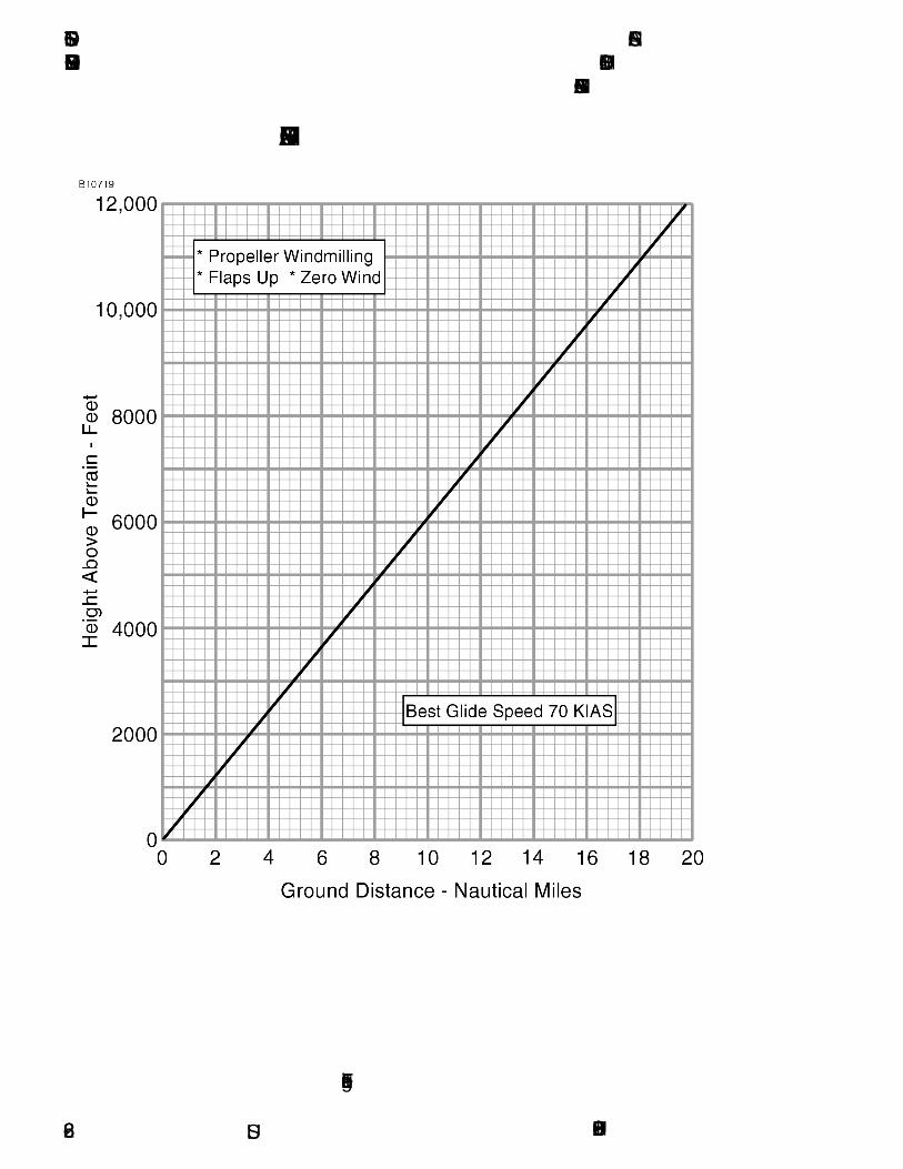
SECTION 6 CESSNAEMERGENCY PROCEDURES MODEL 162
GARMIN G300
U.S.
MAXIMUM GLIDE
Figure 6-1
162PHUS-006-28

CESSNA SECTION 6MODEL 162 EMERGENCY PROCEDURESGARMIN G300
U.S.
FORCED LANDINGS
If all attempts to restart the engine fail and a forced landing is imminent,select a suitable field and prepare for the landing as discussed underthe Emergency Landing Without Engine Power checklist. TransmitMayday message on 121.5 MHz giving location, intentions and squawk7700.
Before attempting an off airport landing with engine power available,one should fly over the landing area at a safe, but low altitude, toinspect the terrain for obstructions and surface conditions, proceedingas discussed in the Precautionary Landing With Engine Powerchecklist.
Prepare for ditching by securing or jettisoning heavy objects located inthe baggage area and collect folded coats for protection of occupants'face at touchdown. Transmit Mayday messages on 121.5 MHz givinglocation, intentions and squawk 7700. Avoid a landing flare because ofthe difficulty in judging height over a water surface. The checklistassumes the availability of power to make a precautionary waterlanding. If power is not available, use of the airspeeds noted withminimum flap extension will provide a more favorable attitude for apower off ditching.
In a forced landing situation, DO NOT turn off the MASTER switch (BATside) or AVN MASTER switch before the landing is assured unlessspecifically instructed by the emergency procedure checklist.Premature deactivation of these switches will disable all airplaneelectrical systems. Note however there are specific emergencyprocedures (such as Electrical Fire) which do require the MASTERswitch (ALT side) to be turned off. Exercise caution when performingthese procedures to ensure that only the ALT side is selected off.
Before completing a forced landing, especially in remote andmountainous areas, activate the ELT by pressing the ELT ON switchlocated on the right instrument panel. For complete information on ELToperation, refer to Section 10, Supplements.
162PHUS-00 6-29
SECTION 6 CESSNAEMERGENCY PROCEDURES MODEL 162
GARMIN G300
U.S.
LANDING WITHOUT ELEVATOR CONTROL
Using throttle and electric elevator trim switch, trim for horizontal flightat 55-60 KIAS with flaps 25° selected. Then do not change theelevator trim or the flap setting ; control the glide angle by makingsmall changes in power.
Power changes should be made slowly and smoothly. The electricelevator trim is powerful. It is best to bump, or pulse, the trim switch tomake changes. Holding the trim switch can result in over trimming andmay start a Pilot Induced Oscillation (PIO) condition resulting in chasingthe trim. If this occurs, it is best to let the airplane stabilize then startagain by just bumping the trim switch.
When in the flare, the elevator trim switch should be pulsed aft towardthe full-nose-up position at the same time slowly reducing power so thatthe airplane is rotated to a slightly nose-above-the-horizon attitude fortouchdown. During the landing flare or round-out, the nose will comedown when power is reduced and the airplane may touch down on thenosewheel before the main wheels. Maintain directional control andclose the throttle at touchdown.
FIRES
Although engine fires are extremely rare in flight, if a fire isencountered, the steps of the appropriate checklist should be followed.After completion of the checklist procedure, execute a forced landing.Do not attempt to restart the engine. The first sign of an electrical fire isusually the smell of burning insulation. The checklist procedure forelectrical fires calls for electrical power to be turned off. All flightinstruments and navigation will be lost at this time. The checklistprocedure should result in the elimination of the fire. When the fire isextinguished, electrical power may be turned on to those systems notinvolved. Navigation and flight information, if unaffected, should bereposted to instruments within 1-2 minutes. If the fire is notextinguished, a rapid descent should be initiated and the electricalsystem turned back on. This may provide airspeed and altitude data inpreparation for a forced landing.
162PHUS-006-30

CESSNA SECTION 6MODEL 162 EMERGENCY PROCEDURESGARMIN G300
U.S.
EMERGENCY OPERATION IN CLOUDS
The Model 162 Skycatcher is not equipped or certified for IFR flight.The following instructions assume that the pilot is not very proficient atinstrument flying and is flying the airplane without the autopilotengaged.
EXECUTING A 180° TURN IN CLOUDS (ADAHRS FAILED)
Upon inadvertently entering the clouds, an immediate turn to reversecourse and return to VFR conditions should be made. With ADAHRSFAILED, magnetometer (magnetic) heading information is notavailable. The G300 map display should be configured with theCOMPASS ARC from the MAP SET-UP menu. The COMPASS ARCwill provide GPS derived heading information on the moving mapdisplay. GPS derived heading information is not as accurate asmagnetic heading; it will provide a means of situational awareness andthe moving map can provide navigation. Other GPS information suchas track (TRK), etc. are also available with a functioning G300 system.Refer to the G300 Pilot's Guide.
If the optional magnetic compass is installed, the magnetic compassmaybe used in place of the G300 compass arc. The magnetic compasswill be subject to normal magnetic compass A.N.D.S. variations duringmaneuvering.
(Continued Next Page)
162PHUS-01 6-31

SECTION 6 CESSNAEMERGENCY PROCEDURES MODEL 162
GARMIN G300
U.S.
EMERGENCY OPERATION IN CLOUDS (Continued)
EMERGENCY DESCENT THROUGH CLOUDS (ADAHRSFAILED)
When returning to VFR flight after a 180° turn is not practical, a descentthrough the clouds to VFR conditions below may be appropriate. Ifpossible, obtain an ATC assistance and clearance for an emergencydescent through the clouds.
Before descending into the clouds, prepare for a stabilized descent asfollows:
1. Reference optional magnetic compass (if installed) or selectG300 map with COMPASS ARC from MAP SET-UP menu forGPS derived approximate heading information on moving mapdisplay.
2. If MFD is installed, select the INFO page and reference the GPSALTITUDE. GPS ALTITUDE is not the same as barometricaltitude but it will give an altitude approximation.
3. TERRAIN - Select G300 TERRAIN - ON. If RED terrain warningis issued, apply full power and climb at 58 KIAS estimated. Stallwarning will provide approximate 5 knot stall warning margin.
4. Monitor Ground Speed (GS) - GPS derived GS in combinationwith GPS derived wind vector information will allowapproximation of airspeed.
5. MIXTURE Control - RICH (push full in)6. CARB HEAT Control Knob - ON (pull full out)7. THROTTLE Control - REDUCE (1700 - 1800 RPM)8. Approximate Airspeed - 70 - 75 Knots (estimate airspeed from
GS and wind vector data)9. Elevator Trim - ADJUST (as required)10. Maintain descent - procedure will provide 500 TO 800 FT/MIN
descent rate.11. Upon breaking out of clouds, resume normal cruising flight.
(Continued Next Page)
162PHUS-016-32

CESSNA SECTION 6MODEL 162 EMERGENCY PROCEDURESGARMIN G300
U.S.
EMERGENCY OPERATION IN CLOUDS (Continued)
RECOVERY FROM SPIRAL DIVE IN THE CLOUDS(ADAHRS FAILED)
ADAHRS FAILURE
If a spiral is entered while in the clouds, continue as follows:1. THROTTLE Control - IDLE (pull full out)2. Remove feet from rudder pedals.3. Stop turn by carefully leveling the wings using aileron control
while referencing COMPASS ARC or optional magneticcompass (if installed) and moving map for heading and turninformation.
4. Cautiously apply elevator back pressure to slowly reduceairspeed to approximately 70 KIAS. Monitor speed and do notreduce airspeed below 70 KIAS. Slowly advance throttle toapproximate 1700-1800 RPM as speed reaches 70-75 Knots.
5. Elevator Trim - ADJUST (maintain 70-75 KIAS glide speed)6. Use aileron control to maintain wings level and constant
heading.7. CARB HEAT Control Knob - ON (pull full out)8. Clear engine occasionally, but avoid using enough power to
disturb the trimmed glide.9. Resume EMERGENCY DESCENT THROUGH THE CLOUDS
procedure. 10. Upon breaking out of clouds, resume normal cruising flight.
162PHUS-01 6-33
SECTION 6 CESSNAEMERGENCY PROCEDURES MODEL 162
GARMIN G300
U.S.
INADVERTENT FLIGHT INTO ICING CONDITIONS
Flight into icing conditions is prohibited and extremely dangerous.While an inadvertent encounter with these conditions can be resolvedusing the checklist procedures, the best action is to turn back orchange altitude immediately to escape icing conditions.
Watch for signs of pitot-static icing and ice accretion on the unheatedpitot tube. If airspeed and altimeter indications become unreliable, GPSderived flight information can provide approximate values for back-up.GPS derived ground speed (GS) and GPS ALTITUDE on the MFDINFO page (if installed) may be used for comparison to barometricinstruments. GPS ALTITUDE information also replaces barometricaltitude in the TERRAIN Page PROFILE window (indicated by a whitearrowhead) when the ADAHRS is inoperative.
In the event of an icing encounter, an unexplained loss of engine powercould be caused by carburetor ice or ice blocking the air intake filter.Should this happen, apply full carburetor heat and adjust throttle toobtain maximum RPM. In some instances, the throttle may need to bereduced for maximum power. The mixture should then be adjusted, asrequired, to obtain maximum RPM. The G300 CARB °F indicatorshould be monitored during carb heat application to ensure carbtemperature rises. Refer to the CARBUETOR ICING AMPLIFIEDEMERGENCY PROCEDURE section.
Maximum cabin heat should be applied, by pulling the CABIN HEATControl Knob to the full out position, in an attempt to clear ice from thewindshield. GPS moving map navigation may assist if ice creates a lossof visibility. If available, select G300 TERRAIN - ON for additionalaltitude and obstacle awareness during reduced visibility. Use of aforward slip can improve forward and over-the-nose landing visibilityinhibited by windshield ice. FLAPS should NOT be used for landing ifairframe ice is present.
The autopilot, if installed, should be disconnected at first indication ofairframe icing and remain disconnected after any icing encounter dueto the possibility of unseen residual ice on the airframe.
162PHUS-006-34

CESSNA SECTION 6MODEL 162 EMERGENCY PROCEDURESGARMIN G300
U.S.
SPINS
Should an inadvertent spin occur, the following recovery procedureshould be used:
1. IMMEDIATELY RETARD THROTTLE TO IDLE POSITION.2. PLACE AILERONS IN NEUTRAL POSITION.3. APPLY AND HOLD FULL RUDDER OPPOSITE TO THE
DIRECTION OF ROTATION AND MOVE CONTROL STICKBRISKLY FORWARD FAR ENOUGH TO BREAK THE STALL.Full down elevator may be required at aft center of gravityloadings to assure optimum recoveries.
4. HOLD THESE CONTROL INPUTS UNTIL ROTATION STOPS.Premature relaxation of the control inputs may extend therecovery.
5. AS ROTATION STOPS, NEUTRALIZE RUDDER, WINGSLEVEL, FLAPS UP AND MAKE A SMOOTH RECOVERYFROM THE RESULTING DIVE. AVOID OVERSTRESSINGAND OVERSPEEDING THE AIRFRAME.
NOTE
If the rate of the spin makes determining the direction ofrotation difficult, the magenta turn rate trend vector in theheading strip over the PFD Attitude Indicator will show therate and direction of the turn. The HSI compass card willrotate in the opposite direction. Hold full rudder opposite thedirection of the turn indicated by the turn rate trend vector.
162PHUS-00 6-35
SECTION 6 CESSNAEMERGENCY PROCEDURES MODEL 162
GARMIN G300
U.S.
ROUGH ENGINE OPERATION OR LOSS OF POWER
CARBURETOR ICING
A gradual loss of RPM and eventual engine roughness may result fromthe formation of carburetor ice. To clear the ice, apply full throttle andpull the CARB HEAT control knob full out until the engine runssmoothly; then reduce carburetor heat and readjust throttle asnecessary. Monitor the G300 CARB °F indicator to verify the carburetortemperature rises out of the amber caution range. If conditions requirethe continued use of carburetor heat in cruise flight, use the minimumamount of heat necessary to prevent ice from forming and lean themixture for smoothest engine operation. The G300 CARB °F indicatorprovides advisory information but does not replace the need to monitorengine condition and adjust carburetor heat or mixture as needed forsafe engine performance.
SPARK PLUG FOULING
A slight engine roughness in flight may be caused by one or more sparkplugs becoming fouled by carbon or lead deposits. This may be verifiedby turning the MAGNETOS switch momentarily from BOTH to either Lor R position. An obvious power loss in single magneto operation isevidence of spark plug or magneto trouble. Leaning the mixture to therecommended lean setting for cruising flight may resolve a spark plugfouling issue. If the problem does not clear up in several minutes,determine if a richer mixture setting will produce smoother operation. Ifnot, proceed to the nearest airport for repairs using the BOTH positionof the MAGNETOS switch unless extreme roughness makes the use ofa single MAGNETO position necessary.
MAGNETO MALFUNCTION
Sudden engine roughness or misfiring is usually a sign of a magnetoproblem. Changing the MAGNETOS switch from BOTH to the L and Rswitch positions will identify which magneto is malfunctioning. Selectdifferent power settings and enrichen the mixture to determine ifcontinued operation on BOTH magnetos is possible. If not, change tothe good magneto and continue to the nearest airport for repairs.
(Continued Next Page)
162PHUS-006-36

CESSNA SECTION 6MODEL 162 EMERGENCY PROCEDURESGARMIN G300
U.S.
ROUGH ENGINE OPERATION OR LOSS OF POWER(Continued)
IDLE POWER ENGINE ROUGHNESS
An excessively rich idle fuel flow may cause low speed engineroughness during flight. During most in-flight low engine speeds (poweroff stalls, approach to landing, etc.), the mixture control is normally inthe full-rich position. However, to improve engine roughness during lowengine speeds while in flight, you should rotate the vernier mixturecontrol to lean of fuel mixture. You may also have to lean the fuelmixture if this low engine speed results in power loss and you need torestart the engine during flight. In all cases, you should land theairplane at the nearest airport for repairs if low speed engine roughnessrequires you to adjust the fuel mixture control to improve engineoperation.
LOW OIL PRESSURE
If the low oil pressure indicator (OIL PSI) turns red, and oil temperatureindicator (OIL °F) remains normal, it is possible that the oil pressuresending unit or relief valve is malfunctioning. Land at the nearest airportto determine the source of the problem.
If a total loss of oil pressure and a rise in oil temperature occur at aboutthe same time, it could mean that the engine is about to fail. Reducepower immediately and select a field suitable for a forced landing. Useonly the minimum power necessary to reach the landing site.
162PHUS-00 6-37

SECTION 6 CESSNAEMERGENCY PROCEDURES MODEL 162
GARMIN G300
U.S.
ELECTRICAL POWER SUPPLY SYSTEMMALFUNCTIONS
Malfunctions in the electrical power supply system can be detectedthrough regular monitoring of the main battery ammeter (AMPS) andthe electrical bus voltmeter (VOLTS); however, the cause of thesemalfunctions is usually difficult to determine. A broken alternator shaft,excessive brush wear, or an internal wiring issue is most likely thecause of alternator failures, although other factors could cause theproblem. Problems of this nature constitute an electrical emergencyand should be dealt with immediately. Electrical power malfunctionsusually fall into two categories: excessive rate of charge and insufficientrate of charge. The following paragraphs describe the recommendedremedy for each situation.
EXCESSIVE RATE OF CHARGE
After engine starting and heavy electrical usage at low engine speeds,such as extended taxiing, the battery condition may be low enough toaccept above normal charging during the initial part of a flight.However, after thirty minutes of cruising flight, the main batteryammeter (AMPS) should be indicating less than 5 amps of charging (+)current. If the charging current remains above this value on a longflight, the battery electrolyte could overheat and evaporate.
Electronic components in the electrical system can be adverselyaffected by higher than normal voltage. The built-in overvoltageprotection circuit will automatically disconnect the alternator if thecharge voltage increases to more than 16.5 volts. If the overvoltagesensor circuit does not operate correctly, as shown by voltage morethan 16.5 volts on the electrical bus voltmeter, the MASTER switch ALTsection should be set to the OFF position. Unnecessary electricalequipment should be de-energized and the flight terminated as soon aspractical.
If excessive rate of charge is indicated but the electrical bus voltmeterindicates less than 15 volts, no immediate action is required. Continuemonitoring and land as soon as practical.
(Continued Next Page)
162PHUS-006-38
CESSNA SECTION 6MODEL 162 EMERGENCY PROCEDURESGARMIN G300
U.S.
ELECTRICAL POWER SUPPLY SYSTEMMALFUNCTIONS (Continued)
INSUFFICIENT RATE OF CHARGE
When the overvoltage circuit, or other fault, opens the alternator(START/ALT) circuit breaker and de-energizes the alternator, adischarge (-) current will be shown on the main battery ammeter(AMPS) and the red LOW VOLTS annunciator will be displayed on thePFD. The Alternator Internal Control Unit (AICU) can de-energize thealternator due to minor disturbances in the electrical system, resultingin a nuisance opening of the START/ALT circuit breaker. If thishappens, an attempt should be made to energize the alternator system.
To energize the alternator system1. MASTER Switch (ALT Only) - OFF2. START/ALT Circuit Breaker - CHECK IN3. MASTER Switch (ALT Only) - ON
If the problem was a minor AICU disturbance in the electrical system,normal main battery charging will start. A charge (+) current will beshown on the main battery ammeter (AMPS) and the LOW VOLTSannunciator will go off.
If the red LOW VOLTS annunciator is displayed and a discharge (-)current is still shown on the AMPS Indicator, there is an alternatorsystem problem. Do not repeat steps to energize the alternator system.Decrease the electrical load on the battery by de-energizingnonessential electrical equipment and avionics (consider exterior lightsand radio equipment) because the battery can supply the electricalsystem for only a short time. Reduce electrical load as soon as possibleto extend the life of the battery for landing. Land as soon as practical.
162PHUS-00 6-39

SECTION 6 CESSNAEMERGENCY PROCEDURES MODEL 162
GARMIN G300
U.S.
OTHER EMERGENCIES
WINDSHIELD DAMAGE
If a bird strike or other incident should damage the windshield in flight tothe point of creating an opening, a significant loss in performance maybe expected. Decrease airspeed and set power as necessary tomaintain best glide speed (70 KIAS) to minimize stress on windshieldand airframe structure. If airplane performance or other adverseconditions prevent landing at an airport, prepare for an off airportlanding in accordance with the PRECAUTIONARY LANDING WITHENGINE POWER or DITCHING checklists.
G300 FAILURES
The Garmin G300 system provides all flight and engine instrumentinformation via the Air Data Attitude and Heading Reference System(ADAHRS) unit. Individual sensors within the ADAHRS unit provide airand flight data information as well as serve as the central gateway forthe engine data displayed on the Primary Flight Display (PFD) andoptional Multi-Function Display (MFD).
Failure of the ADAHRS unit or the individual sensors may leave onlyGPS derived flight data for situational awareness and navigation. Thepilot should be thoroughly familiar with the G300 operation, page andinformation location, and methods of accessing the GPS flight databefore beginning any flight in the Model 162 Skycatcher. It isrecommended that the pilot step through each of the G300 emergencyprocedures in the Emergency Procedures Checklist for familiarizationbefore operating the aircraft.
Failure of the G300 PFD display will cause an automatic reversion ofthe PFD display to the MFD display (if installed). Failure of the PFDwithout an installed MFD display will leave the pilot to rely largely onexternal cues for pilotage and navigation. The Emergency ProceduresChecklist contains suggestions for managing a successful PFD failureand landing. It is recommended that the pilot become familiar with thischecklist before operating the airplane.
162PHUS-016-40
CESSNA SECTION 7MODEL 162 NORMAL PROCEDURESGARMIN G300
NORMAL PROCEDURES
TABLE OF CONTENTSPage
Introduction . . . . . . . . . . . . . . . . . . . . . . . . . . . . . . . . . . . . . . . . . . . .7-3
Airspeeds For Normal Operation . . . . . . . . . . . . . . . . . . . . . . . . . . . .7-3
NORMAL PROCEDURES. . . . . . . . . . . . . . . . . . . . . . . . . . . . . .7-4Preflight Inspection . . . . . . . . . . . . . . . . . . . . . . . . . . . . . . . . . . . . . .7-4
Cabin. . . . . . . . . . . . . . . . . . . . . . . . . . . . . . . . . . . . . . . . . . . . . . .7-5Left Wing . . . . . . . . . . . . . . . . . . . . . . . . . . . . . . . . . . . . . . . . . . . .7-6Left Wing Leading Edge . . . . . . . . . . . . . . . . . . . . . . . . . . . . . . . .7-8Left Wing Trailing Edge . . . . . . . . . . . . . . . . . . . . . . . . . . . . . . . . .7-8Empennage. . . . . . . . . . . . . . . . . . . . . . . . . . . . . . . . . . . . . . . . . .7-8Right Wing Trailing Edge. . . . . . . . . . . . . . . . . . . . . . . . . . . . . . . .7-9Right Wing. . . . . . . . . . . . . . . . . . . . . . . . . . . . . . . . . . . . . . . . . . .7-9Nose . . . . . . . . . . . . . . . . . . . . . . . . . . . . . . . . . . . . . . . . . . . . . . 7-11
Before Starting Engine. . . . . . . . . . . . . . . . . . . . . . . . . . . . . . . . . . .7-13Starting Engine (With Battery) . . . . . . . . . . . . . . . . . . . . . . . . . . . . 7-13Starting Engine (With External Power) . . . . . . . . . . . . . . . . . . . . . .7-15Before Takeoff . . . . . . . . . . . . . . . . . . . . . . . . . . . . . . . . . . . . . . . . .7-18Takeoff . . . . . . . . . . . . . . . . . . . . . . . . . . . . . . . . . . . . . . . . . . . . . . .7-19
Normal Takeoff . . . . . . . . . . . . . . . . . . . . . . . . . . . . . . . . . . . . . .7-19Short Field Takeoff . . . . . . . . . . . . . . . . . . . . . . . . . . . . . . . . . . .7-19
Enroute Climb . . . . . . . . . . . . . . . . . . . . . . . . . . . . . . . . . . . . . . . . .7-20Cruise . . . . . . . . . . . . . . . . . . . . . . . . . . . . . . . . . . . . . . . . . . . . . . .7-20Descent . . . . . . . . . . . . . . . . . . . . . . . . . . . . . . . . . . . . . . . . . . . . . .7-20Before Landing . . . . . . . . . . . . . . . . . . . . . . . . . . . . . . . . . . . . . . . .7-20Landing . . . . . . . . . . . . . . . . . . . . . . . . . . . . . . . . . . . . . . . . . . . . . .7-21
Normal Landing. . . . . . . . . . . . . . . . . . . . . . . . . . . . . . . . . . . . . .7-21Short Field Landing . . . . . . . . . . . . . . . . . . . . . . . . . . . . . . . . . . .7-21Balked Landing . . . . . . . . . . . . . . . . . . . . . . . . . . . . . . . . . . . . . .7-21
After Landing . . . . . . . . . . . . . . . . . . . . . . . . . . . . . . . . . . . . . . . . . .7-22Securing Airplane . . . . . . . . . . . . . . . . . . . . . . . . . . . . . . . . . . . . . 7-22
(Continued Next Page)
U.S.162PHUS-01 7-1
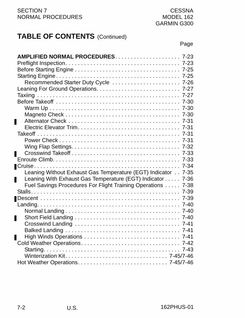
SECTION 7 CESSNANORMAL PROCEDURES MODEL 162
GARMIN G300
TABLE OF CONTENTS (Continued)Page
AMPLIFIED NORMAL PROCEDURES . . . . . . . . . . . . . . . . . . . . . 7-23Preflight Inspection. . . . . . . . . . . . . . . . . . . . . . . . . . . . . . . . . . . . . 7-23Before Starting Engine . . . . . . . . . . . . . . . . . . . . . . . . . . . . . . . . . . 7-25Starting Engine . . . . . . . . . . . . . . . . . . . . . . . . . . . . . . . . . . . . . . . . 7-25
Recommended Starter Duty Cycle . . . . . . . . . . . . . . . . . . . . . . 7-26Leaning For Ground Operations. . . . . . . . . . . . . . . . . . . . . . . . . . . 7-27Taxiing . . . . . . . . . . . . . . . . . . . . . . . . . . . . . . . . . . . . . . . . . . . . . . 7-27Before Takeoff . . . . . . . . . . . . . . . . . . . . . . . . . . . . . . . . . . . . . . . . 7-30
Warm Up . . . . . . . . . . . . . . . . . . . . . . . . . . . . . . . . . . . . . . . . . . 7-30Magneto Check . . . . . . . . . . . . . . . . . . . . . . . . . . . . . . . . . . . . . 7-30Alternator Check . . . . . . . . . . . . . . . . . . . . . . . . . . . . . . . . . . . . 7-31Electric Elevator Trim. . . . . . . . . . . . . . . . . . . . . . . . . . . . . . . . . 7-31
Takeoff . . . . . . . . . . . . . . . . . . . . . . . . . . . . . . . . . . . . . . . . . . . . . . 7-31Power Check . . . . . . . . . . . . . . . . . . . . . . . . . . . . . . . . . . . . . . . 7-31Wing Flap Settings. . . . . . . . . . . . . . . . . . . . . . . . . . . . . . . . . . . 7-32Crosswind Takeoff . . . . . . . . . . . . . . . . . . . . . . . . . . . . . . . . . . . 7-33
Enroute Climb. . . . . . . . . . . . . . . . . . . . . . . . . . . . . . . . . . . . . . . . . 7-33Cruise . . . . . . . . . . . . . . . . . . . . . . . . . . . . . . . . . . . . . . . . . . . . . . . 7-34
Leaning Without Exhaust Gas Temperature (EGT) Indicator . . 7-35Leaning With Exhaust Gas Temperature (EGT) Indicator . . . . . 7-36Fuel Savings Procedures For Flight Training Operations . . . . . 7-38
Stalls. . . . . . . . . . . . . . . . . . . . . . . . . . . . . . . . . . . . . . . . . . . . . . . . 7-39Descent . . . . . . . . . . . . . . . . . . . . . . . . . . . . . . . . . . . . . . . . . . . . . 7-39Landing. . . . . . . . . . . . . . . . . . . . . . . . . . . . . . . . . . . . . . . . . . . . . . 7-40
Normal Landing . . . . . . . . . . . . . . . . . . . . . . . . . . . . . . . . . . . . . 7-40Short Field Landing . . . . . . . . . . . . . . . . . . . . . . . . . . . . . . . . . . 7-40Crosswind Landing . . . . . . . . . . . . . . . . . . . . . . . . . . . . . . . . . . 7-41Balked Landing . . . . . . . . . . . . . . . . . . . . . . . . . . . . . . . . . . . . . 7-41High Winds Operations . . . . . . . . . . . . . . . . . . . . . . . . . . . . . . . 7-41
Cold Weather Operations. . . . . . . . . . . . . . . . . . . . . . . . . . . . . . . . 7-42Starting. . . . . . . . . . . . . . . . . . . . . . . . . . . . . . . . . . . . . . . . . . . . 7-43Winterization Kit. . . . . . . . . . . . . . . . . . . . . . . . . . . . . . . . . 7-45/7-46
Hot Weather Operations. . . . . . . . . . . . . . . . . . . . . . . . . . . . . 7-45/7-46
U.S. 162PHUS-017-2

CESSNA SECTION 7MODEL 162 NORMAL PROCEDURESGARMIN G300
U.S.
INTRODUCTIONSection 7 provides procedures and amplified instructions for normaloperations using standard and simply operated optional equipment.Normal procedures associated with more complex optional equipmentcan be found in Section 10, Supplements.
AIRSPEEDS FOR NORMAL OPERATIONUnless otherwise noted, the following speeds are based on a maximumweight of 1320 pounds and may be used for any lesser weight.
TAKEOFFNormal Climb . . . . . . . . . . . . . . . . . . . . . . . . . . . . . . . . 65 - 75 KIASShort Field Takeoff, Flaps 10°, Speed at 50 Feet . . . . . . . . .55 KIAS
ENROUTE CLIMB, FLAPS UPNormal, Sea Level. . . . . . . . . . . . . . . . . . . . . . . . . . . . . 65 - 75 KIASBest Rate of Climb . . . . . . . . . . . . . . . . . . . . . . . . . . . . . . . .62 KIASBest Angle of Climb. . . . . . . . . . . . . . . . . . . . . . . . . . . . . . . .57 KIAS
LANDING APPROACHNormal Approach, Flaps UP . . . . . . . . . . . . . . . . . . . . . 60 - 70 KIASNormal Approach, Flaps FULL . . . . . . . . . . . . . . . . . . . 55 - 65 KIASShort Field Approach, Flaps FULL . . . . . . . . . . . . . . . . . . . .50 KIAS
BALKED LANDINGMaximum Power, Flaps 25° . . . . . . . . . . . . . . . . . . . . . . . . .50 KIAS
MAXIMUM RECOMMENDED TURBULENT AIRPENETRATION SPEED
1320 POUNDS . . . . . . . . . . . . . . . . . . . . . . . . . . . . . . . . . . .89 KIAS1200 POUNDS . . . . . . . . . . . . . . . . . . . . . . . . . . . . . . . . . . .85 KIAS1100 POUNDS . . . . . . . . . . . . . . . . . . . . . . . . . . . . . . . . . . .80 KIAS
MAXIMUM DEMONSTRATED CROSSWIND VELOCITYTakeoff or Landing. . . . . . . . . . . . . . . . . . . . . . . . . . . . . . .12 KNOTS
MAXIMUM RECOMMENDED WIND VELOCITYAll Operations . . . . . . . . . . . . . . . . . . . . . . . . . . . . . . . . . .22 KNOTS
162PHUS-02 7-3

SECTION 7 CESSNANORMAL PROCEDURES MODEL 162
GARMIN G300
NORMAL PROCEDURESPREFLIGHT INSPECTION
NOTE
Visually check airplane for general condition during walk-around inspection. Airplane should be parked in a normalground attitude (refer to Figure 1-1) to make sure that fueldrain valves allow for accurate sampling. In cold weather,remove even small accumulations of frost, ice or snow fromwing, tail and control surfaces. Also, make sure that controlsurfaces contain no internal accumulations of ice or debris.If a night flight is planned, check operation of all lights, andmake sure a flashlight is available.
Figure 7-1
U.S. 162PHUS-007-4
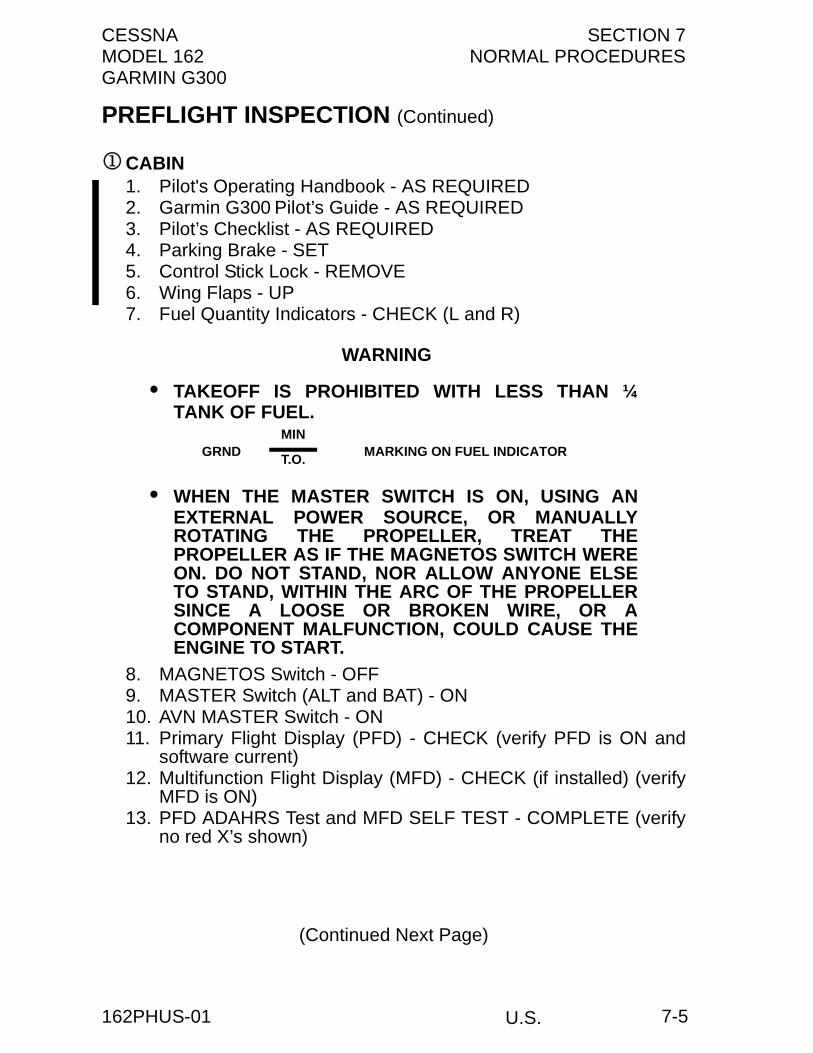
CESSNA SECTION 7MODEL 162 NORMAL PROCEDURESGARMIN G300
PREFLIGHT INSPECTION (Continued)
1CABIN1. Pilot's Operating Handbook - AS REQUIRED2. Garmin G300 Pilot’s Guide - AS REQUIRED3. Pilot’s Checklist - AS REQUIRED4. Parking Brake - SET5. Control Stick Lock - REMOVE6. Wing Flaps - UP7. Fuel Quantity Indicators - CHECK (L and R)
WARNING
• TAKEOFF IS PROHIBITED WITH LESS THAN ¼TANK OF FUEL.
• WHEN THE MASTER SWITCH IS ON, USING ANEXTERNAL POWER SOURCE, OR MANUALLYROTATING THE PROPELLER, TREAT THEPROPELLER AS IF THE MAGNETOS SWITCH WEREON. DO NOT STAND, NOR ALLOW ANYONE ELSETO STAND, WITHIN THE ARC OF THE PROPELLERSINCE A LOOSE OR BROKEN WIRE, OR ACOMPONENT MALFUNCTION, COULD CAUSE THEENGINE TO START.
8. MAGNETOS Switch - OFF9. MASTER Switch (ALT and BAT) - ON10. AVN MASTER Switch - ON11. Primary Flight Display (PFD) - CHECK (verify PFD is ON and
software current)12. Multifunction Flight Display (MFD) - CHECK (if installed) (verify
MFD is ON)13. PFD ADAHRS Test and MFD SELF TEST - COMPLETE (verify
no red X’s shown)
(Continued Next Page)
GRNDMIN
MARKING ON FUEL INDICATORT.O.
U.S.162PHUS-01 7-5

SECTION 7 CESSNANORMAL PROCEDURES MODEL 162
GARMIN G300
PREFLIGHT INSPECTION (Continued)
1CABIN (Continued)
14. LOW VOLTS Annunciator - CHECK (verify annunciator isshown)
NOTE
LOW VOLTS Annunciator will only be shown if batteryvoltage is less than 12.5 volts. Verify battery voltage onPFD/MFD ENG page.
15. Elevator Trim Control - T/O POSITION16. Avionics Cooling Fan - CHECK (verify fan is operational)17. Airplane Weight and Balance - CHECKED and ENTERED18. AVN MASTER Switch - OFF19. MASTER Switch (ALT and BAT) - OFF20. Fire Extinguisher - CHECK (if installed) (verify gage pointer in
green arc)
2LEFT WING1. Cabin Door - CHECK (security and condition)2. Main Wheel Tire - CHECK (proper inflation and general
condition (weather checks, tread depth and wear, etc.))3. Brake Line - CHECK (security and condition)4. Wheel Fairings - CHECK (security and condition) (if installed)5. Fresh Air Vent - CHECK (blockage)6. Fuel Quantity - CHECK VISUALLY (for desired level)
WARNING
TAKEOFF IS PROHIBITED WITH LESS THAN ¼ TANKOF FUEL.
7. Fuel Filler Cap - SECURE and VENT CLEAR
(Continued Next Page)
GRNDMIN
MARKING ON FUEL INDICATORT.O.
U.S. 162PHUS-007-6

CESSNA SECTION 7MODEL 162 NORMAL PROCEDURESGARMIN G300
PREFLIGHT INSPECTION (Continued)
2LEFT WING (Continued)8. Fuel Tank Sump Quick Drain Valves - DRAIN
Drain at least a cupful of fuel (using sampler cup) from eachsump location to check for water, sediment, and proper fuelgrade before each flight and after each refueling. If water isobserved, take further samples until clear and then gently rockwings and lower tail to the ground to move any additionalcontaminants to the sampling points. Take repeated samplesfrom all fuel drain points until all contamination has beenremoved. If contaminants are still present, refer to WARNINGbelow and do not fly airplane.
NOTE
Collect all sampled fuel in a safe container. Dispose of thesampled fuel so that it does not cause a nuisance, hazard,or damage to the environment.
WARNING
IF, AFTER REPEATED SAMPLING, EVIDENCE OFCONTAMINATION STILL EXISTS, THE AIRPLANESHOULD NOT BE FLOWN. TANKS SHOULD BEDRAINED AND SYSTEM PURGED BY QUALIFIEDMAINTENANCE PERSONNEL. ALL EVIDENCE OFCONTAMINATION MUST BE REMOVED BEFOREFURTHER FLIGHT.
(Continued Next Page)
U.S.162PHUS-00 7-7
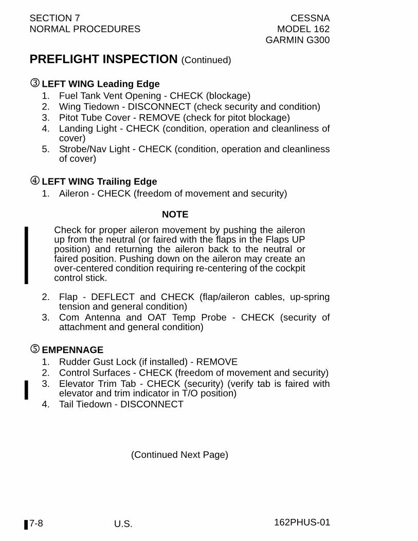
SECTION 7 CESSNANORMAL PROCEDURES MODEL 162
GARMIN G300
PREFLIGHT INSPECTION (Continued)
3LEFT WING Leading Edge1. Fuel Tank Vent Opening - CHECK (blockage)2. Wing Tiedown - DISCONNECT (check security and condition)3. Pitot Tube Cover - REMOVE (check for pitot blockage)4. Landing Light - CHECK (condition, operation and cleanliness of
cover)5. Strobe/Nav Light - CHECK (condition, operation and cleanliness
of cover)
4LEFT WING Trailing Edge1. Aileron - CHECK (freedom of movement and security)
NOTE
Check for proper aileron movement by pushing the aileronup from the neutral (or faired with the flaps in the Flaps UPposition) and returning the aileron back to the neutral orfaired position. Pushing down on the aileron may create anover-centered condition requiring re-centering of the cockpitcontrol stick.
2. Flap - DEFLECT and CHECK (flap/aileron cables, up-springtension and general condition)
3. Com Antenna and OAT Temp Probe - CHECK (security ofattachment and general condition)
5EMPENNAGE1. Rudder Gust Lock (if installed) - REMOVE2. Control Surfaces - CHECK (freedom of movement and security)3. Elevator Trim Tab - CHECK (security) (verify tab is faired with
elevator and trim indicator in T/O position)4. Tail Tiedown - DISCONNECT
(Continued Next Page)
U.S. 162PHUS-017-8
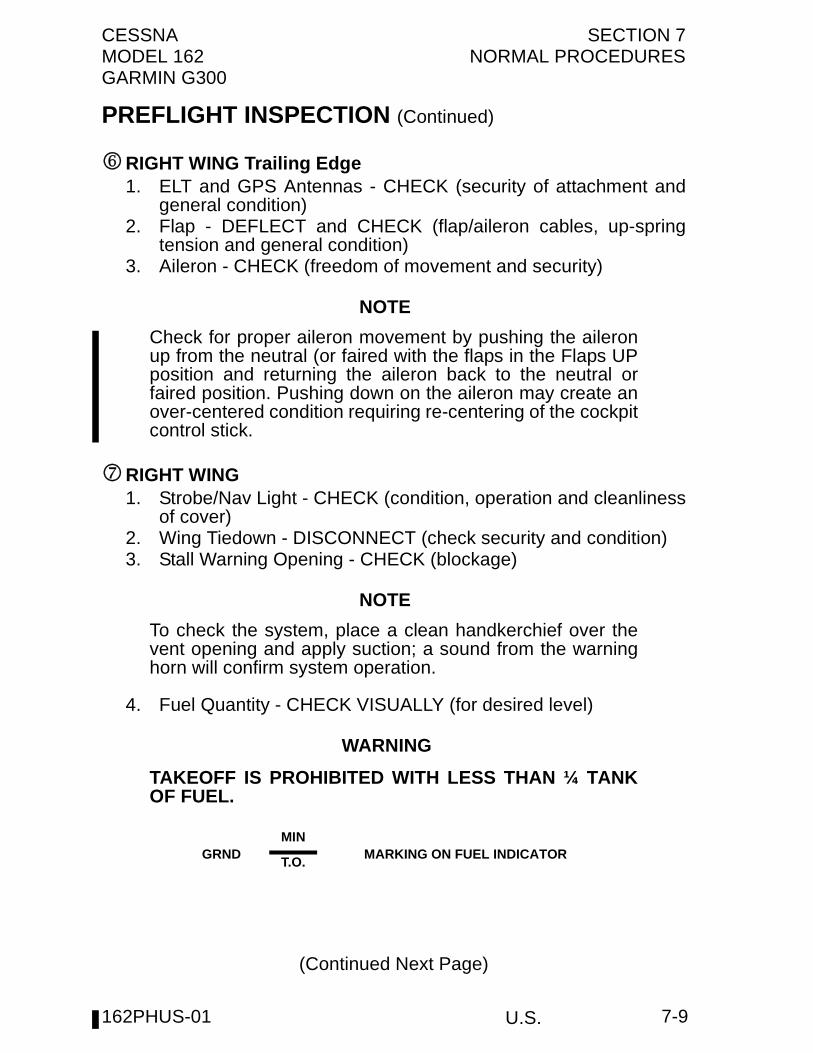
CESSNA SECTION 7MODEL 162 NORMAL PROCEDURESGARMIN G300
PREFLIGHT INSPECTION (Continued)
6RIGHT WING Trailing Edge1. ELT and GPS Antennas - CHECK (security of attachment and
general condition)2. Flap - DEFLECT and CHECK (flap/aileron cables, up-spring
tension and general condition)3. Aileron - CHECK (freedom of movement and security)
NOTE
Check for proper aileron movement by pushing the aileronup from the neutral (or faired with the flaps in the Flaps UPposition and returning the aileron back to the neutral orfaired position. Pushing down on the aileron may create anover-centered condition requiring re-centering of the cockpitcontrol stick.
7RIGHT WING1. Strobe/Nav Light - CHECK (condition, operation and cleanliness
of cover)2. Wing Tiedown - DISCONNECT (check security and condition)3. Stall Warning Opening - CHECK (blockage)
NOTE
To check the system, place a clean handkerchief over thevent opening and apply suction; a sound from the warninghorn will confirm system operation.
4. Fuel Quantity - CHECK VISUALLY (for desired level)
WARNING
TAKEOFF IS PROHIBITED WITH LESS THAN ¼ TANKOF FUEL.
(Continued Next Page)
GRNDMIN
MARKING ON FUEL INDICATORT.O.
U.S.162PHUS-01 7-9
SECTION 7 CESSNANORMAL PROCEDURES MODEL 162
GARMIN G300
PREFLIGHT INSPECTION (Continued)
7RIGHT WING (Continued)5. Fuel Filler Cap - SECURE and VENT CLEAR6. Main Wheel Tire - CHECK (proper inflation and general
condition (weather checks, tread depth and wear, etc.))7. Brake Line - CHECK (security and condition)8. Wheel Fairings - CHECK (security and condition) (if installed)9. Fuel Tank Sump Quick Drain Valves - DRAIN
Drain at least a cupful of fuel (using sampler cup) from eachsump location to check for water, sediment, and proper fuelgrade before each flight and after each refueling. If water isobserved, take further samples until clear and then gently rockwings and lower tail to the ground to move any additionalcontaminants to the sampling points. Take repeated samplesfrom all fuel drain points until all contamination has beenremoved. If contaminants are still present, refer to WARNINGbelow and do not fly airplane.
NOTE
Collect all sampled fuel in a safe container. Dispose of thesampled fuel so that it does not cause a nuisance, hazardor damage to the environment.
WARNING
IF, AFTER REPEATED SAMPLING, EVIDENCE OFCONTAMINATION STILL EXISTS, THE AIRPLANESHOULD NOT BE FLOWN. TANKS SHOULD BEDRAINED AND SYSTEM PURGED BY QUALIFIEDMAINTENANCE PERSONNEL. ALL EVIDENCE OFCONTAMINATION MUST BE REMOVED BEFOREFURTHER FLIGHT.
10. Cabin Door - CHECK (security and condition)11. Fresh Air Vent - CHECK (blockage)
U.S. 162PHUS-017-10

CESSNA SECTION 7MODEL 162 NORMAL PROCEDURESGARMIN G300
PREFLIGHT INSPECTION (Continued)
8NOSE1. Engine Cooling Air Inlets - CHECK (clear of obstructions)2. Propeller and Spinner - CHECK (for nicks and security)3. Air Filter - CHECK (for condition and blockage by dust or other
foreign matter)4. Nosewheel Strut and Tire - CHECK (strut and general condition
of tire (weather checks, tread depth and wear, etc.))5. Nosewheel Fairing - CHECK (security and condition) (if
installed)6. Engine Exhaust Outlet - CHECK (security and condition)7. Engine Oil Dipstick/Filler Cap:
a. Oil level - CHECK b. Dipstick/filler cap - SECURE (lever horizontal and facing aft)
NOTE
Do not operate with less than 3.5 quarts. Fill to 5 quartsfor extended flight.
8. Fuel Strainer Quick Drain Valve - DRAIN (bottom left side ofengine cowling)Drain at least a cupful of fuel (using sampler cup) from valve tocheck for water, sediment, and proper fuel grade before eachflight and after each refueling. If water is observed, take furthersamples until clear and then gently rock wings and lower tail tothe ground to move any additional contaminants to the samplingpoints. Take repeated samples from all fuel drain points,including the fuel strainer and fuel sump valve, until allcontamination has been removed. If contaminants are stillpresent, refer to WARNING below and do not fly the airplane.
NOTE
Collect all sampled fuel in a safe container. Dispose of thesampled fuel so that it does not cause a nuisance, hazard,or damage to the environment.
(Continued Next Page)
U.S.162PHUS-00 7-11
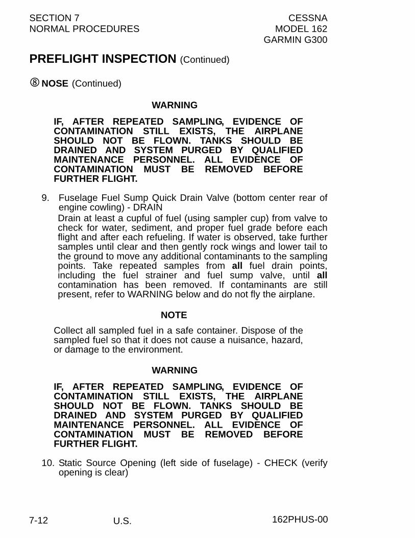
SECTION 7 CESSNANORMAL PROCEDURES MODEL 162
GARMIN G300
PREFLIGHT INSPECTION (Continued)
8NOSE (Continued)
WARNING
IF, AFTER REPEATED SAMPLING, EVIDENCE OFCONTAMINATION STILL EXISTS, THE AIRPLANESHOULD NOT BE FLOWN. TANKS SHOULD BEDRAINED AND SYSTEM PURGED BY QUALIFIEDMAINTENANCE PERSONNEL. ALL EVIDENCE OFCONTAMINATION MUST BE REMOVED BEFOREFURTHER FLIGHT.
9. Fuselage Fuel Sump Quick Drain Valve (bottom center rear ofengine cowling) - DRAINDrain at least a cupful of fuel (using sampler cup) from valve tocheck for water, sediment, and proper fuel grade before eachflight and after each refueling. If water is observed, take furthersamples until clear and then gently rock wings and lower tail tothe ground to move any additional contaminants to the samplingpoints. Take repeated samples from all fuel drain points,including the fuel strainer and fuel sump valve, until allcontamination has been removed. If contaminants are stillpresent, refer to WARNING below and do not fly the airplane.
NOTE
Collect all sampled fuel in a safe container. Dispose of thesampled fuel so that it does not cause a nuisance, hazard,or damage to the environment.
WARNING
IF, AFTER REPEATED SAMPLING, EVIDENCE OFCONTAMINATION STILL EXISTS, THE AIRPLANESHOULD NOT BE FLOWN. TANKS SHOULD BEDRAINED AND SYSTEM PURGED BY QUALIFIEDMAINTENANCE PERSONNEL. ALL EVIDENCE OFCONTAMINATION MUST BE REMOVED BEFOREFURTHER FLIGHT.
10. Static Source Opening (left side of fuselage) - CHECK (verifyopening is clear)
U.S. 162PHUS-007-12
CESSNA SECTION 7MODEL 162 NORMAL PROCEDURESGARMIN G300
BEFORE STARTING ENGINE1. Preflight Inspection - COMPLETE2. Passenger Briefing - COMPLETE3. Rudder Pedals - ADJUST4. Seat Belts - ADJUST and SECURE5. Cabin Doors - AS DESIRED6. Brakes - TEST and SET7. Circuit Breakers - CHECK IN8. Electrical Equipment - OFF9. AVN Master Switch - OFF
CAUTION
THE AVIONICS MASTER SWITCH MUST BE OFFDURING ENGINE START TO PREVENT POSSIBLEDAMAGE TO AVIONICS.
10. FUEL SHUTOFF Valve - ON (push full in)
STARTING ENGINE (With Battery)
IF FUEL PRIMER CONTROL INSTALLED1. Fuel PRIMER Control - AS REQUIRED
a. Engine COLD - PUMP (1 to 3 strokes)b. Engine WARM - NONE
IF FUEL PRIMER CONTROL NOT INSTALLED1. THROTTLE Control - AS REQUIRED
a. Engine COLD - PUMP (3 to 6 strokes)b. Engine WARM - PUMP ONCE (push full in and pull full out)
STARTING ENGINE (With Battery) (Continued)2. CARB HEAT Control Knob - OFF (push full in)3. THROTTLE Control - AS REQUIRED
a. Engine COLD - OPEN 1/4 INCHb. Engine WARM - CLOSED
4. MIXTURE Control - FULL RICH (push full in)
(Continued Next Page)
U.S.162PHUS-01 7-13

SECTION 7 CESSNANORMAL PROCEDURES MODEL 162
GARMIN G300
STARTING ENGINE (With Battery) (Continued)
5. AVN MASTER Switch - OFF6. MASTER Switch (ALT and BAT) - ON7. Engine Indicating System - CHECK PARAMETERS (verify no
red X's through indicators)8. VOLTS - CHECK EIS ENGINE PAGE
NOTE
A red LOW VOLTS annunciator will come on when batteryvoltage is less than 12.5 volts. As battery voltagedecreases, the Garmin G300 display will become lessbright and eventually unreadable. If the starter fails to crankthe engine or the G300 display becomes unreadable,service battery or apply external power.
9. AMPS - CHECK (verify discharge shown (negative))10. Propeller Area - CLEAR (verify that all people and equipment
are at a safe distance from the propeller)11. STROBE Light Switch - ON12. MAGNETOS Switch - START (release when engine starts)
NOTE
If the engine is primed too much (flooded), place themixture control in the IDLE CUTOFF position, open thethrottle control 1/2 to full, and engage the starter motor(START). When the engine starts, advance the mixturecontrol to the FULL RICH position and promptly retard thethrottle control.
13. Oil Pressure - CHECK (verify that oil pressure increases above10 PSI into the YELLOW BAND range in 30 seconds)
14. AMPS - CHECK (verify charge shown (positive))15. NAV Light Switch - ON (as required)16. STROBE Light Switch - OFF17. AVN MASTER Switch - ON18. MIXTURE Control - LEAN (as required)
U.S. 162PHUS-017-14

CESSNA SECTION 7MODEL 162 NORMAL PROCEDURESGARMIN G300
STARTING ENGINE (With External Power) (if installed)
IF FUEL PRIMER CONTROL INSTALLED1. Fuel PRIMER Control - AS REQUIRED
a. Engine COLD - PUMP (1 to 3 strokes)b. Engine WARM - NONE
IF FUEL PRIMER CONTROL NOT INSTALLED1. THROTTLE Control - AS REQUIRED
a. Engine COLD - PUMP (3 to 6 strokes)b. Engine WARM - PUMP ONCE (push full in and pull full out)
STARTING ENGINE (With External Power) (Continued)2. CARB HEAT Control Knob - OFF (push full in)3. THROTTLE Control - AS REQUIRED
a. Engine COLD - OPEN 1/4 INCHb. Engine WARM - CLOSED
4. MIXTURE Control - FULL RICH (push full in)5. AVN MASTER Switch - OFF6. MASTER Switch (ALT and BAT) - ON7. Engine Indicating System - CHECK PARAMETERS (verify no
red X's through indicators)8. VOLTS - CHECK EIS ENGINE PAGE
NOTE
A red LOW VOLTS annunciator will come on when batteryvoltage is less than 12.5 volts. As battery voltagedecreases, the Garmin G300 display will become lessbright and eventually unreadable. If the G300 displaybecomes unreadable, connect external power per thefollowing procedure. The battery may require servicing.
9. AMPS - CHECK (verify discharge shown (negative))10. MASTER Switch (ALT and BAT) - OFF11. EXTERNAL POWER - CONNECT (to external power
receptacle)12. MASTER Switch (ALT and BAT) - ON
(Continued Next Page)
U.S.162PHUS-01 7-15
SECTION 7 CESSNANORMAL PROCEDURES MODEL 162
GARMIN G300
STARTING ENGINE (With External Power) (if installed)(Continued)
13. Engine Indicating System - CHECK PARAMETERS (verify nored X's through indicators)
14. VOLTS - CHECK EIS ENGINE PAGE (verify 12.5 to 15.0 voltsindication and LOW VOLTS annunciation is not shown)
15. AMPS - CHECK (verify charge shown (positive))16. Propeller Area - CLEAR (verify that all people and equipment
are at a safe distance from the propeller)17. STROBE Lights Switch - ON18. MAGNETOS Switch - START (release when engine starts)
NOTE
If the engine is primed too much (flooded), place themixture control in the IDLE CUTOFF position, open thethrottle control 1/2 to full, and engage the starter motor(START). When the engine starts, advance the mixturecontrol to the FULL RICH position and promptly retard thethrottle control.
19. Oil Pressure - CHECK (verify that oil pressure increases above10 PSI into the YELLOW BAND range in 30 seconds)
20. Power - REDUCE TO IDLE21. EXTERNAL POWER - DISCONNECT FROM GROUND
POWER (latch external power receptacle door)22. Power - INCREASE (to approximately 1500 RPM for several
minutes to charge battery)23. AMPS - CHECK (verify charge shown (positive))24. VOLTS - CHECK EIS ENGINE PAGE (verify 12.5 VOLTS
minimum shown)25. LOW VOLTS Annunciator - CHECK (verify annunciator is not
shown)
(Continued Next Page)
U.S. 162PHUS-017-16

CESSNA SECTION 7MODEL 162 NORMAL PROCEDURESGARMIN G300
STARTING ENGINE (With External Power) (if installed)(Continued)
26. Internal Power - CHECKa. MASTER Switch (ALT) - OFFb. LDG Light Switch - ONc. NAV Light Switch - ONd. THROTTLE Control - REDUCE TO IDLEe. MASTER Switch (ALT) - ONf. THROTTLE Control - INCREASE (to approximately 1500
RPM)g. AMPS - CHECK (verify charge shown (positive))
WARNING
IF AMMETER DOES NOT SHOW POSITIVE CHARGE (+AMPS), REMOVE THE BATTERY FROM THE AIRPLANEAND SERVICE OR REPLACE THE BATTERY BEFOREFLIGHT.
27. LDG Light Switch - OFF (as required)28. STROBE Light Switch - OFF29. AVN MASTER Switch - ON30. MIXTURE Control - LEAN (as required)
U.S.162PHUS-00 7-17
SECTION 7 CESSNANORMAL PROCEDURES MODEL 162
GARMIN G300
U.S.
BEFORE TAKEOFF1. Parking Brake - SET
a. Brakes - Applyb. PARKING BRAKE Control Knob - ON (pull full out)
2. Seats and Seat Belts - CHECK SECURE3. Cabin Doors - CLOSED and LOCKED4. Flight Controls - FREE and CORRECT5. Flight Instruments (PFD) - CHECK (verify no red X's through
indicators)6. Engine Indicating System - CHECK PARAMETERS (verify no
red X's through indicators)7. Altimeter - SET8. Fuel Quantity Indicators - CHECK (verify level is correct)
WARNING
TAKEOFF IS PROHIBITED WITH LESS THAN ¼ TANKOF FUEL.
9. PRIMER Control Knob (if installed) - IN and LOCKED10. MIXTURE Control - RICH11. Autopilot - ENGAGE (if installed) (push AP button on autopilot
control panel)a. Flight Controls - CHECK (verify autopilot can be
overpowered in both pitch and roll axes)b. A/P DISC Button - PRESS (if installed)
(verify autopilot disengages and aural alert is heard)12. Elevator Trim Control Switch - SET FOR T/O13. THROTTLE Control - 1700 RPM (once oil temperature is above
75°F and oil pressure in green band range)a. MAGNETOS Switch - CHECK (RPM drop should not
exceed 150 RPM on either magneto or 50 RPM differentialbetween magnetos)
b. Engine Indicators - CHECKc. CARB HEAT Control Knob - ON
(1) Engine RPM - CHECK (verify RPM decreases)(2) CARB °F - CHECK (verify temp increases)
d. AMPS and VOLTS - CHECK
(Continued Next Page)
GRNDMIN
MARKING ON FUEL INDICATORT.O.
162PHUS-017-18

CESSNA SECTION 7MODEL 162 NORMAL PROCEDURESGARMIN G300
U.S.
BEFORE TAKEOFF (Continued)
14. Annunciators - CHECK (verify no annunciators are shown)15. THROTTLE Control - CHECK IDLE (900 RPM or LESS)16. THROTTLE Control Friction Lock - ADJUST17. COM Frequency - SET18. GPS Flight Plan - AS DESIRED19. XPDR - SET20. Wing Flaps - UP - 10° (10° recommended)21. NAV Light Switch - ON22. STROBE Light Switch - ON23. PARKING BRAKE Control Knob - OFF (push full in)
TAKEOFF
NORMAL TAKEOFF1. Wing Flaps - UP - 10° (10° recommended)2. CARB HEAT Control Knob - OFF (push full in)3. THROTTLE Control - FULL (push full in)4. MIXTURE Control - RICH (above 5000 feet pressure altitude,
lean for maximum RPM)5. Directional Control - MAINTAIN (use differential braking until
rudder control becomes effective)6. Elevator Control - LIFT NOSEWHEEL AT 50 KIAS7. Climb Airspeed - 65 - 75 KIAS8. Wing Flaps - RETRACT (at safe altitude)
SHORT FIELD TAKEOFF1. Wing Flaps - 10°2. CARB HEAT Control Knob - OFF (push full in)3. Brakes - APPLY4. THROTTLE Control - FULL (push full in)5. MIXTURE Control - RICH (above 5000 feet pressure altitude,
lean for maximum RPM)6. Brakes - RELEASE7. Elevator Control - SLIGHTLY TAIL LOW8. Directional Control - MAINTAIN (use differential braking until
rudder control becomes effective)9. Climb Airspeed - 55 KIAS (until all obstacles are cleared)10. Wing Flaps - RETRACT SLOWLY (when airspeed is more than
60 KIAS)
162PHUS-01 7-19

SECTION 7 CESSNANORMAL PROCEDURES MODEL 162
GARMIN G300
U.S.
ENROUTE CLIMB1. Airspeed - 65 - 75 KIAS2. THROTTLE Control - FULL (push full in)3. MIXTURE Control - RICH (above 5000 feet pressure altitude,
lean for maximum RPM)
NOTE
For maximum performance climb speeds, refer to Section5, Figure 5-5, Maximum Rate of Climb at 1320 Pounds.
CRUISE1. Power - 2400 - 2750 RPM (75% recommended)2. Elevator Trim Control Switch - ADJUST3. MIXTURE Control - LEAN (for best power setting)
DESCENT1. Power - AS DESIRED (2750 RPM maximum)2. MIXTURE Control - ADJUST (if necessary to make engine run
smoothly)3. Altimeter - SET4. Wing Flaps - AS DESIRED (UP - 10° below 100 KIAS)
(10° - 25° below 85 KIAS)(25° - FULL below 70 KIAS)
5. CARB HEAT Control Knob - ON (as required)
BEFORE LANDING1. Seats and Seat Belts - SECURED and LOCKED2. MIXTURE Control - RICH (push full in) (below 5000 feet
pressure altitude)3. CARB HEAT Control Knob - ON (pull full out) (apply full heat
before reducing power)4. LDG Light Switch - ON5. Autopilot - OFF (if installed)
162PHUS-017-20

CESSNA SECTION 7MODEL 162 NORMAL PROCEDURESGARMIN G300
U.S.
LANDING
NORMAL LANDING1. Airspeed - 60 - 70 KIAS (Flaps UP)2. Wing Flaps - AS DESIRED (UP - 10° below 100 KIAS)
(10° - 25° below 85 KIAS)(25° - FULL below 70 KIAS)
3. Airspeed - 55 - 65 KIAS (Flaps FULL)4. Elevator Trim Control Switch - ADJUST5. Touchdown - MAIN WHEELS FIRST6. Landing Roll - LOWER NOSEWHEEL GENTLY7. Braking - MINIMUM REQUIRED8. Directional Control - MAINTAIN (with rudder and differential
braking)
SHORT FIELD LANDING1. Airspeed - 60 - 70 KIAS (Flaps UP)2. Wing Flaps - FULL3. Airspeed - 50 KIAS (until flare)4. Elevator Trim Control - ADJUST5. Power - REDUCE TO IDLE (as obstacle is cleared)6. Touchdown - MAIN WHEELS FIRST7. Brakes - APPLY HEAVILY (while maintaining directional control)8. Wing Flaps - UP
BALKED LANDING1. THROTTLE Control - FULL (push full in)2. CARB HEAT Control Knob - OFF (push full in)3. Wing Flaps - RETRACT to 25°4. Climb Speed - 50 KIAS (until obstacle is cleared)5. Climb Speed - 60 KIAS (after obstacle is cleared)6. Wing Flaps - 10°, then UP (after reaching a safe altitude and 60
KIAS)
162PHUS-01 7-21

SECTION 7 CESSNANORMAL PROCEDURES MODEL 162
GARMIN G300
U.S.
AFTER LANDING1. CARB HEAT Control Knob - OFF (push full in)2. Wing Flaps - UP3. STROBE Light Switch - OFF4. Transponder - STBY
SECURING AIRPLANE1. Parking Brake - SET
a. Brakes - APPLYb. PARKING BRAKE Control Knob - ON (pull full out)
2. THROTTLE Control - IDLE (pull full out)3. Electrical Equipment - OFF4. AVN MASTER Switch - OFF5. MIXTURE Control - IDLE CUTOFF (pull full out)6. MAGNETOS Switch - OFF7. MASTER Switch (ALT and BAT) - OFF8. Control Lock - INSTALL
162PHUS-007-22

CESSNA SECTION 7MODEL 162 NORMAL PROCEDURESGARMIN G300
U.S.
AMPLIFIED NORMAL PROCEDURES
PREFLIGHT INSPECTION
The preflight inspection, described in Figure 7-1 and adjacent checklist,is required prior to each flight. If the airplane has been in extendedstorage, has had recent major maintenance, or has been operated fromrough runways, a more extensive exterior inspection is recommended.
Before every flight, check the condition of main and nose landing geartires. Keep tires inflated to the pressure specified in Section 8, AirplaneHandling, Service And Maintenance. Examine tire sidewalls forpatterns of shallow cracks called weather checks. These cracks areevidence of tire deterioration caused by age, improper storage, orprolonged exposure to weather. Check the tread of the tire for depth,wear, and cuts. Replace the tire if fibers are visible.
After major maintenance has been performed, the flight and trim tabcontrols should be double checked for free and correct movement andsecurity. The security of all inspection plates on the airplane should bechecked following periodic inspections. If the airplane has been waxedor polished, check the external static pressure source hole forstoppage.
If the airplane has been kept in a crowded hangar, it should be checkedfor dents and scratches on wings, fuselage, and tail surfaces, damageto navigation/strobe light assemblies, wing tip fairings and avionicsantennas. Check for damage to the nosewheel travel stops and wheelfairings (if installed), resulting from exceeding nosewheel turning limitswhile towing.
Outside storage for long periods may result in dust and dirtaccumulation on the induction air filter, obstructions in airspeed systemlines, water contaminants in fuel tanks, and insect/bird/rodent nests inany opening. If any water is detected in the fuel system, the fuel tanksump quick drain valves, fuel sump quick drain valve, and fuselagesump quick drain valve should all be thoroughly drained again. Thewings should then be gently rocked and the tail lowered to the groundto move any further contaminants to the sampling points. Repeatedsamples should then be taken at all quick drain points until allcontamination has been removed.
(Continued Next Page)
162PHUS-00 7-23
SECTION 7 CESSNANORMAL PROCEDURES MODEL 162
GARMIN G300
U.S.
PREFLIGHT INSPECTION (Continued)
NOTE
Collect all sampled fuel in a safe container. Dispose of thesampled fuel so that it does not cause a nuisance, hazard,or damage to the environment.
WARNING
IF, AFTER REPEATED SAMPLING, EVIDENCE OFCONTAMINATION STILL EXISTS, THE AIRPLANESHOULD NOT BE FLOWN. TANKS SHOULD BEDRAINED AND SYSTEM PURGED BY QUALIFIEDMAINTENANCE PERSONNEL. ALL EVIDENCE OFCONTAMINATION MUST BE REMOVED BEFOREFURTHER FLIGHT.
When parked on the ramp, care should be exercised to make surewings are level or the left wing slightly higher to prevent fuel fromdripping from the fuel vent when fuel tanks are full. To prevent loss offuel in flight, make sure the fuel tank filler caps are tightly sealed afterany fuel system check or servicing. Fuel system vents should also beinspected for obstructions, ice or water, especially after exposure tocold, wet weather.
If the airplane has been stored outside in windy or gusty areas, or tieddown adjacent to taxiing airplanes, special attention should be paid tocontrol surface stops, hinges, and brackets to detect the presence ofpotential wind damage.
Airplanes that are operated from rough fields, especially at highaltitudes, are subjected to abnormal landing gear abuse. Frequentlycheck all components of the landing gear, strut, tires, and brakes. If theairplane has been operated from muddy fields or in snow or slush,check the main and nose gear wheel fairings for obstructions andcleanliness.
Operation from a gravel or cinder field will require extra attention topropeller tips and abrasion on leading edges of the horizontal tail.Stone damage to the propeller can seriously reduce the fatigue life ofthe blades.
162PHUS-007-24

CESSNA SECTION 7MODEL 162 NORMAL PROCEDURESGARMIN G300
U.S.
BEFORE STARTING ENGINE
Rudder pedals should be adjusted fore and aft as needed to ensure thepilot has full brake deflection with the rudder fully deflected. A smallpercentage of pilots may require additional cushions to correctlyposition themselves for visibility and control.
Ideally, the pilot should be positioned so that the outboard elbownaturally rests on the door armrest and the control stick falls within thehand of that arm. Correct positioning allows for relaxed flying usingwrist movements and assists the new pilot to adjusting to theSkycatcher flight controls.
STARTING ENGINE
Engine starting can differ depending on the temperature of the engineand surrounding ambient air which affects the amount of fuel primingrequired. Standard priming is done using the throttle control. Pumpingthe throttle, by rapidly advancing the throttle control fully in and out,works an accelerator pump in the engine carburetor for priming. In thisway, the throttle may be pumped or given some number of "strokes" toprovide the required prime. An optional plunger style primer may beused to provide fuel prime (if installed).
If the engine is already warm, pump the throttle once then leave thethrottle closed to start. No additional priming should be required. A coldengine with moderately warm (room temperature) ambient air willrequire 1 or 2 strokes of the throttle (or primer). A cold engine with coldambient air (temperatures above freezing) will require up to 3 or 4strokes of throttle (or primer). A cold engine should have the throttleopen approximately ¼ inch for start.
In extremely cold temperatures, it may be necessary to continuepriming while cranking the engine. If the engine is under primed, mostlikely in cold weather with a cold engine, it will not fire at all, andadditional priming will be necessary. As soon as the cylinders begin tofire, open the throttle slightly to keep it running.
(Continued Next Page)
162PHUS-01 7-25

SECTION 7 CESSNANORMAL PROCEDURES MODEL 162
GARMIN G300
STARTING ENGINE (Continued)
Weak intermittent firing followed by puffs of black smoke from theexhaust stack indicates over priming or flooding. Excess fuel can becleared from the combustion chambers by the following procedure: setparking brake and hold brakes, set the mixture control full lean (idlecutoff) and the place throttle control to full open; then crank the enginethrough several revolutions with the starter. Be prepared to immediatelyreduce throttle control to idle once engine starts. Repeat the startingprocedure without any additional priming.
After starting, if the oil pressure gage does not begin to show pressurewithin 30 seconds in the summertime and about twice that long in verycold weather, stop the engine and investigate. Lack of oil pressure cancause serious engine damage. After starting, avoid the use ofcarburetor heat unless icing conditions prevail.
NOTE
Additional details concerning cold weather starting andoperation may be found under COLD WEATHEROPERATION paragraphs in this section.
After the completion of normal engine starting procedures, it is a goodpractice to verify that the engine starter has disengaged. If the startercontactor were to stick closed, causing the starter to remain engaged,an excessively high charge indication (full scale at 1000 RPM) wouldbe evident on the ammeter. In this event, immediately shut downengine and have electrical system inspected by qualified maintenancepersonnel prior to next flight.
RECOMMENDED STARTER DUTY CYCLE
Operate the starter motor for 10 seconds followed by a 20 second cooldown period. This cycle can be repeated five additional times, followedby a thirty minute cool down period before resuming cranking. Aftercool down, operate the starter motor again, six cycles of 10 secondsfollowed by 20 seconds of cool down. If the engine still does not start,try to find the cause.
U.S. 162PHUS-017-26
CESSNA SECTION 7MODEL 162 NORMAL PROCEDURESGARMIN G300
LEANING FOR GROUND OPERATIONS
For all ground operations, after starting the engine and when theengine is running smoothly:
1. THROTTLE Control - 1200 RPM2. Mixture Control - ADJUST (lean for maximum RPM)3. THROTTLE Control - ADJUST for ground operation (800 to
1000 RPM recommended)
NOTE
If ground operation will be required after the BEFORETAKEOFF checklist is completed, lean the mixture again(as described above) until ready for the TAKEOFFchecklist.
TAXIING
CAUTION
DUE TO LOWER WEIGHTS AND SLOWER STALLSPEEDS THAN LARGER AIRPLANES, PROPER TAXITECHNIQUES SHOULD BE USED IN WINDYCONDITIONS. OPERATIONS IN WIND CONDITIONSABOVE 22 KNOTS ARE NOT RECOMMENDED.
When taxiing, the combination of differential braking and free-castoringnose wheel provide excellent ground maneuvering in tight spaces aswell as control during normal taxiing. Differential brake applicationshould be done by firm, short taps of the brake pedal so as to nudgethe airplane in the desired direction. Excess speed and "riding a brake"should be avoided since this can cause brake heating, brake fade, orloss of braking effectiveness resulting in loss of control or stoppingability.
It is important that taxi speed be held to that of a brisk walk and all flightcontrols be utilized up to their maximum deflection (refer to Figure 7-2,Taxiing Diagram) to aid in maintaining directional control. This isparticularly important in windy conditions.
(Continued Next Page)
U.S.162PHUS-00 7-27
SECTION 7 CESSNANORMAL PROCEDURES MODEL 162
GARMIN G300
TAXIING (Continued)
NOTE
Strong or gusty tail winds can over power the wing flapreturn springs causing the flaps to randomly blow downwhile taxiing. Selecting flaps to FULL when taxing with atailwind can prevent the blow down. Use caution to preventa build-up of taxi speed due to blowing by strong tailwinds.Flaps should be retracted when turning away from thetailwind condition and the BEFORE TAKEOFF Checklistshould be used to insure flaps are properly reset beforetakeoff.
The CARB HEAT control knob should be pushed full in to the OFFposition during all ground operations unless carb heat is absolutelynecessary to correct engine roughness. When the CARB HEAT controlknob is pulled out to the ON position, air entering the engine is notfiltered. However, if needed, use FULL CARB HEAT until engineroughness clears. Monitoring the CARB ºF Indicator will assist inamount of carb heat required to keep the carburetor temperature out ofthe yellow caution range and prevent engine roughness.
Taxiing over loose gravel or cinders should be done at the lowestengine RPM possible to avoid abrasion and stone damage to thepropeller tips.
(Continued Next Page)
U.S. 162PHUS-007-28

CESSNA SECTION 7MODEL 162 NORMAL PROCEDURESGARMIN G300
TAXIING (Continued)
TAXIING DIAGRAM
NOTE
Strong quartering tail winds require caution. Avoid suddenbursts of the throttle and sharp braking when the airplane isin this attitude. Use differential braking and rudder tomaintain direction.
Figure 7-2
U.S.162PHUS-00 7-29
SECTION 7 CESSNANORMAL PROCEDURES MODEL 162
GARMIN G300
BEFORE TAKEOFF
WARM UP
If the engine idles with the throttle against the idle stop, approximately700 to 800 RPM and accelerates smoothly, the engine is warm enoughfor takeoff. Since the engine is closely cowled for efficient in-flightengine cooling, the airplane should be pointed into the wind to avoidoverheating during prolonged engine operation on the ground. Refer toLeaning For Ground Operations procedures to prevent spark plugfouling that can occur from long periods of idling and prolonged groundoperations.
MAGNETO CHECK
CAUTION
MAKE SURE ENGINE OIL TEMPERATURE IS ABOVE75ºF AND OIL PRESSURE IS WITHIN THE GREEN BANDRANGE PRIOR TO PREFORMING A MAGNETO CHECK.
The magneto check must be made at 1700 RPM. Turn theMAGNETOS switch from the BOTH position to the R position. Note thenew RPM, then turn the MAGNETOS switch back to the BOTH positionto clear the spark plugs. Turn the MAGNETOS switch to the L position,note the new RPM, then turn the switch back to the BOTH position.RPM decrease should not be more than 150 RPM on either magneto orbe greater than 50 RPM differential between magnetos. If there is adoubt concerning operation of the ignition system, RPM checks athigher engine speeds will usually confirm whether a deficiency exists.
No RPM drop may indicate a faulty ground to one magneto or magnetotiming set in advance of the angle specified.
(Continued Next Page)
U.S. 162PHUS-017-30

CESSNA SECTION 7MODEL 162 NORMAL PROCEDURESGARMIN G300
BEFORE TAKEOFF (Continued)
ALTERNATOR CHECK
The alternator should be checked for proper operation before everyflight. Electrical power is essential for all flight instrumentation,navigation, and radio operation. Check the electrical system during theMAGNETO check (1700 RPM) by setting all electrical equipmentrequired for the flight to the ON position. When the alternator isoperating properly, the ammeters will show zero or positive current (+amps), the voltmeter will show 13 to 15 volts, and the LOW VOLTSannunciator will not be shown on the PFD. Reduce the electrical loadbefore reducing engine speed so the battery will not discharge whilethe engine is at idle.
ELECTRIC ELEVATOR TRIM
Make sure the elevator trim tab is in the takeoff position when the trimpointer is aligned with the T/O index mark on the EIS TRIM indicator.Adjust the trim during flight as necessary to make control wheel forcesmore neutral.
TAKEOFF
POWER CHECK
It is important to check full throttle engine operation early in the takeoffroll. Any sign of rough engine operation or sluggish engine accelerationis good cause for discontinuing the takeoff. If this occurs, you arejustified in making a thorough full throttle static run-up before anothertakeoff is attempted. The engine should run smoothly and turnapproximately 2375 - 2475 RPM with carburetor heat off and themixture leaned to provide maximum RPM.
NOTE
Carburetor heat should not be used during takeoff unless itis absolutely necessary to obtain smooth engineacceleration.
(Continued Next Page)
U.S.162PHUS-01 7-31
SECTION 7 CESSNANORMAL PROCEDURES MODEL 162
GARMIN G300
TAKEOFF (Continued)
POWER CHECK (Continued)
Full throttle run-ups over loose gravel are especially harmful topropeller tips. When takeoffs must be made over a gravel surface,advance the throttle slowly. This allows the airplane to start rollingbefore high RPM is developed, and the gravel will be blown behind thepropeller rather than pulled into it.
Prior to takeoff from fields above 5000 feet pressure altitude, themixture should be leaned to give maximum RPM at full throttle, with theairplane not moving.
After full throttle is applied, adjust the throttle friction lock clockwise toprevent the throttle from moving back from a maximum power position.Similar friction lock adjustments should be made as required in otherflight conditions to hold the throttle setting.
WING FLAP SETTINGS
Normal takeoffs use wing flaps UP - 10°. Using 10° wing flaps reducesthe ground roll to lift off while keeping the total distance over anobstacle by equivalent to the flaps UP distances. Flap deflectionsgreater than 10° are not approved for takeoff. If 10° wing flaps areused for takeoff, the flaps should stay at 10° until all obstacles arecleared and a safe flap retraction speed of 60 KIAS is reached. For ashort field, 10° wing flaps and an obstacle clearance speed of 55 KIASshould be used.
Soft or rough field takeoffs are performed with 10° flaps by lifting theairplane off the ground as soon as practical in a slightly tail low attitude.If no obstacles are ahead, the airplane should be leveled offimmediately to accelerate to a higher climb speed. When departing asoft field with an aft C.G. loading, the elevator trim control should beadjusted towards the nose down direction to give comfortable controlwheel forces during the initial climb.
U.S. 162PHUS-017-32
CESSNA SECTION 7MODEL 162 NORMAL PROCEDURESGARMIN G300
TAKEOFF (Continued)
CROSSWIND TAKEOFF
Takeoffs under strong crosswind conditions normally are performedwith the minimum flap setting necessary for the field length, to minimizethe drift angle immediately after takeoff. Begin the takeoff with aileronsfully deflected into the wind. As the airplane is accelerated, reduceaileron deflection maintaining directional control down the runway.Reaching a speed slightly higher than normal rotation speed, applygentle back pressure to the elevator control and quickly, but carefully,lift the airplane off the ground. Do not over rotate but keep positive pitchangle and airspeed to prevent possible settling back to the runway.When well clear of the ground, make a coordinated turn into the wind tocorrect for drift.
ENROUTE CLIMB
Normal enroute climbs are performed with flaps up, at full throttle and65 to 75 KIAS for the best combination of performance, visibility andengine cooling. The mixture should be full rich during climb at altitudesup to 5000 feet pressure altitude. Above 5000 feet pressure altitude,the mixture can be leaned as needed for increased power or to providesmoother engine operation.
If it is necessary to climb more rapidly to clear mountains or reachfavorable winds at higher altitudes, the best rate of climb speed is 62KIAS and should be used with Maximum Continuous Power (MCP).
If an obstruction dictates the use of a steep climb angle, the best angleof climb speed is 57 KIAS and should be used with flaps UP and MCP.This type of climb should be of the minimum duration and enginetemperatures should be carefully monitored due to the low climb speed.
U.S.162PHUS-01 7-33
SECTION 7 CESSNANORMAL PROCEDURES MODEL 162
GARMIN G300
CRUISE
Normal cruise is performed between 40% and 75% power. The engineRPM and corresponding fuel consumption for various altitudes can bedetermined by using the data in Section 5.
NOTE
Cruise flight should use 75% power as much as possibleuntil the engine has operated for a total of 50 hours or oilconsumption has stabilized. Operation at this higher powerwill ensure proper seating of the piston rings and isapplicable to new engines, and engines in service followingcylinder replacement or top overhaul of one or morecylinders.
The Cruise Performance charts in Section 5 provide the pilot with flightplanning information for the Model 162 in still air at maximum grossweight without speed fairings installed. Cruise performance may differslightly due to differences in weight and center of gravity location.
The Cruise Performance charts should be used as a guide, along withthe available winds aloft information, to determine the most favorablealtitude, power setting and fuel needed for a given flight.
The selection of cruise altitude on the basis of the most favorable windconditions and the use of low power settings are significant factors thatshould be considered on every trip to reduce fuel consumption.
Proper leaning techniques also contribute to greater range and arefigured into cruise performance tables. To achieve the recommendedlean mixture fuel consumption figures shown in Section 5, the mixtureshould be leaned per recommended procedures.
In the event that unusual conditions cause the intake air filter tobecome clogged or iced over, apply carburetor heat immediately tobypass the intake air filter therefore providing unfiltered heated air asthe alternate air intake. Engine RPM can decrease from a cruise powersetting. This RPM loss should be recovered by increasing the throttlesetting to maintain desired power.
(Continued Next Page)
U.S. 162PHUS-017-34

CESSNA SECTION 7MODEL 162 NORMAL PROCEDURESGARMIN G300
CRUISE (Continued)
Carburetor ice, as evidenced by an unexplained drop in RPM, can beremoved by application of full carburetor heat. Upon regaining theoriginal RPM (with heat off), use the minimum amount of heat(reference EIS CARB ºF display) to prevent ice from forming. Since theheated air causes a richer mixture, readjust the mixture setting whencarburetor heat is to be used continuously in cruise flight.
The use of full carburetor heat is recommended during flight in heavyrain to avoid the possibility of engine stoppage due to excessive wateringestion or carburetor ice. The mixture setting should be readjusted forsmoothest operation. Power changes should be made cautiously,followed by prompt adjustment of the mixture for smoothest operation.
LEANING WITHOUT EXHAUST GAS TEMPERATURE(EGT) INDICATOR
BEST POWER CRUISE
Use the mixture control vernier adjustment to lean the fuel mixture byslowly turning the mixture control knob in the counterclockwisedirection while monitoring engine RPM. As RPM increases, continue tocarefully lean the mixture until it reaches peak RPM. Slightly enrichenmixture (turn mixture control knob clockwise) until a slight drop inengine RPM is indicated. This is the Best Power Cruise setting.
CAUTION
EXCESSIVE LEANING WILL INCREASE ENGINETEMPERATURES AND MAY DAMAGE ENGINE. WHENINCREASING POWER, ENRICHEN MIXTURE, THENADVANCE THE THROTTLE TO INCREASE RPM. WHENREDUCING POWER, RETARD THROTTLE, THENADJUST THE MIXTURE CONTROL.
Lean the mixture for maximum RPM during all operations at anyaltitude, including those below 3000 feet, when using 75% or lesspower. Above 5000 feet, mixture may be leaned for maximum RPMduring full throttle climbs (after engine has accumulated 50 hours).
(Continued Next Page)
U.S.162PHUS-01 7-35

SECTION 7 CESSNANORMAL PROCEDURES MODEL 162
GARMIN G300
CRUISE (Continued)
LEANING WITH EXHAUST GAS TEMPERATURE (EGT)INDICATOR (if installed)
The cruise performance data in this POH is based on therecommended lean mixture setting determined from the maximum orpeak EGT at power settings of 75% MCP and lower.
EGT °F is displayed with a vertical scale and pointer on the EISENGINE page. The numerical value for the EGT is located above thevertical scale.
Use the mixture control vernier adjustment to lean the fuel mixture byslowly turning the mixture control knob in the counterclockwisedirection while monitoring EGT. As EGT °F increases, continue to leanthe mixture until it reaches peak EGT. Enrichen the mixture by slowlyturning the mixture control clockwise and monitor EGT °F until EGTdecreases slightly.
NOTE
The Model 162 engine manufacturer, Teledyne ContinentalMotors, has not approved operation of the engine at fuelflow rates (mixture settings) less than necessary to reachpeak EGT. Refer to Section 5, Figure 5-7, CruisePerformance, for specific power settings and lean for bestpower cruise.
Continuous operation at mixture settings lean of peak EGT isprohibited.
(Continued Next Page)
U.S. 162PHUS-01
7-36
CESSNA SECTION 7MODEL 162 NORMAL PROCEDURESGARMIN G300
CRUISE (Continued)
LEANING WITH EXHAUST GAS TEMPERATURE (EGT)INDICATOR (if installed) (Continued)
CAUTION
EXCESSIVE LEANING WILL INCREASE ENGINETEMPERATURES AND MAY DAMAGE ENGINE. WHENINCREASING POWER, ENRICHEN MIXTURE, THENADVANCE THE THROTTLE TO INCREASE RPM. WHENREDUCING POWER, RETARD THROTTLE, THENADJUST THE MIXTURE CONTROL.
NOTE
• Any change in altitude or power setting will require achange in the recommended lean mixture setting and arecheck of the EGT setting.
• The EGT indicator takes several seconds, after amixture adjustment, to start to show an EGT change.Finding peak EGT and adjusting the mixture to theapplicable setting should take approximately one minutewhen the adjustments are made carefully andaccurately. Adjusting the mixture quickly is notrecommended.
(Continued Next Page)
U.S.162PHUS-01 7-37
SECTION 7 CESSNANORMAL PROCEDURES MODEL 162
GARMIN G300
CRUISE (Continued)
FUEL SAVINGS PROCEDURES FOR FLIGHT TRAININGOPERATIONS
For best fuel economy during flight training operations, the followingprocedures are recommended.
1. After engine start and for all ground operations, set the throttle to1200 RPM and lean the mixture for maximum RPM. Afterleaning, set the throttle to the appropriate RPM for groundoperations. Leave the mixture at this setting until beginning theBEFORE TAKEOFF checklist. If TAKEOFF is delayed aftercompleting the BEFORE TAKEOFF checklist, lean the mixtureagain as described above until ready to perform the TAKEOFFchecklist.
2. Lean the mixture for maximum RPM during full throttle climbsabove 5000 feet. The mixture may remain leaned (maximumRPM at full throttle) for practicing maneuvers such as stalls andslow flight.
3. Lean the mixture for maximum RPM during all operations at anyaltitude, including those below 3000 feet, when using 75% orless power.
NOTE
• When cruising or maneuvering at 75% power or less, themixture may be further leaned to best power cruise. Thisis especially applicable to cross-country training flights,but should be practiced during transition flight to andfrom the practice area as well.
• Using the above recommended procedures can providefuel savings in excess of 5% when compared to typicaltraining operations at full rich mixture. In addition, theabove procedures will minimize spark plug fouling sincethe reduction in fuel consumption results in aproportional reduction in tetraethyl lead passing throughthe engine.
U.S. 162PHUS-01
7-38
CESSNA SECTION 7MODEL 162 NORMAL PROCEDURESGARMIN G300
STALLSThe stall characteristics are conventional for the flaps up and flapsdown conditions and aural warning is provided by a stall warning hornwhich sounds between 5 and 10 knots above the stall in allconfigurations. Power-on stall recovery should be initiated bysimultaneously lowering the nose while reducing power after whichnormal power-off stall recovery techniques should be applied.
CAUTION
INTENTIONAL POWER-ON STALLS SHOULD BELIMITED TO 30 DEGREES NOSE UP PITCH ANGLE.EXCEEDING 30 DEGREES REQUIRES HIGH POWERAND ACCELERATED STALL ENTRY WHICH MAYRESULT IN DISORIENTATION
WARNING
INTENTIONAL SPINS ARE PROHIBITED. REFER TOSECTION 6, EMERGENCY PROCEDURES, SPINS. IT ISRECOMMENDED THAT THESE EMERGENCYPROCEDURES BE MEMORIZED TO ENSURE PROMPTAND PROPER RECOVERY TECHNIQUES ARE USED INTHE EVENT AN INADVERTENT SPIN ISENCOUNTERED.
Refer to Section 5, Figure 5-2, for power-off stall speeds at 1320pounds.
DESCENT Normal descent from altitude may be made with flaps retracted or withflaps extended to increase drag for a steepened descent angle.Caution should be used to observe flap limit speeds. Slips may bemade in all flap configurations and are useful to increase descent rateswhile allowing power to be kept above idle. Carburetor heat should beused as needed for engine roughness and applied before reducingpower to prevent carburetor ice from forming during low power descent.Since heated air causes a richer fuel mixture, readjust the mixturesetting when carburetor heat is to be used for extended descent. If alow power descent is made, it is recommended that the throttle becycled occasionally to check for engine roughness at higher power.
NOTE
Extended low power descents should be avoided during thefirst 25 hours of operation of a new engine.
U.S.162PHUS-01 7-39
SECTION 7 CESSNANORMAL PROCEDURES MODEL 162
GARMIN G300
LANDING
NORMAL LANDING
Normal landing approaches can be made with power on or power offwith any flap setting within the flap airspeed limits. Surface winds andair turbulence are usually the primary factors in determining the mostcomfortable approach speeds. Slips to landing are very effective maybe performed in all flap configurations.
Landing at slower speeds will result in shorter landing distances andminimum wear to tires and brakes. Power should be at idle as the mainwheels touch the ground. The main wheels must touch the groundbefore the nosewheel. The nosewheel must be lowered to the runwaycarefully after the speed has diminished to avoid unnecessary nosegear loads. This procedure is very important for rough or soft fieldlandings. Directional control should be maintained using up to fullrudder deflection and differential braking as necessary.
SHORT FIELD LANDING
For a short field landing in smooth air conditions, approach at 50 KIASwith FULL flaps using enough power to control the glide path. Slightlyhigher approach speeds should be used in turbulent air conditions.After all approach obstacles are cleared, smoothly reduce power andhold the approach speed by lowering the nose of the airplane. Themain wheels must touch the ground before the nosewheel with powerat idle. Immediately after the main wheels touch the ground, carefullylower the nosewheel and apply heavy braking as required. Formaximum brake performance, retract the flaps, hold the control stick fullback, and apply maximum brake pressure without skidding the tires orloosing directional control. Use of full rudder authority will assistdirectional control.
(Continued Next Page)
U.S. 162PHUS-01
7-40
CESSNA SECTION 7MODEL 162 NORMAL PROCEDURESGARMIN G300
LANDING (Continued)
CROSSWIND LANDING
When landing in a strong crosswind, use the minimum flap settingrequired for the field length. Sideslips with full rudder deflection, may bemade in all flap configurations. Although the crab or combinationmethod of drift correction may be used, the wing low method gives thebest control. After touchdown, hold a straight course with the rudderand use up to full aileron deflection as required, and differential brakingas necessary.
The maximum allowable crosswind velocity is dependent upon pilotcapability as well as airplane limitations. Operation in direct crosswindsof 12 knots has been demonstrated (not an operating limitation).
BALKED LANDING
In a balked landing (go-around) climb, reduce the flap setting to 25°immediately after full power is applied and climb at 50 KIAS. Above3000 feet pressure altitude, lean the mixture to obtain maximum RPM.After clearing any obstacles, allow the airplane to accelerate to 60 KIASand carefully retract the flaps to 10°. After clearing any obstacles,carefully retract the flaps and allow the airplane to accelerate to normalclimb airspeed.
HIGH WIND OPERATIONS
Takeoff and landings have been demonstrated in winds up to 22 knotsand crosswinds up to 12 knots. The pilot should be cautious of gustsand turbulence from terrain or buildings when in close proximity toground during takeoff and landing. Prompt and positive control inputsshould be used to counter flight path deviations.
Proper taxi control techniques must be used at all times during groundoperations. Operations in wind conditions above 22 knots are notrecommended.
U.S.162PHUS-01 7-41

SECTION 7 CESSNANORMAL PROCEDURES MODEL 162
GARMIN G300
COLD WEATHER OPERATIONS
Special consideration should be given to the operation of the airplanefuel system during the winter season or prior to any flight in coldtemperatures. Proper preflight draining of the fuel system is especiallyimportant and will eliminate any free water accumulation. The use ofadditives such as isopropyl alcohol or Diethylene Glycol MonomethylEther (DIEGME) may also be desirable. Refer to Section 8, FuelAdditives, for more information on the proper use of fuel additives.
Cold weather often causes conditions that require special care duringairplane operations. Even small accumulations of frost, ice, or snowmust be removed, particularly from wing, tail and all controlsurfaces to assure satisfactory flight performance and handling.Also, control surfaces must be free of any internal accumulations of iceor snow.
If snow or slush covers the takeoff surface, allowance must be made fortakeoff distances which will be increasingly extended as the snow orslush depth increases. The depth and consistency of this cover can, infact, prevent takeoff in many instances.
The Garmin G300 Instrumentation Liquid Crystal Displays (LCD) mayacquire a frosted or cloudy appearance at extremely cold temperatures.The displays may also be very slow to update information when coldsoaked. Proper flight display clarity and flight data update rates mayrequire extended warm-up.
The Garmin G300 EIS engine information is recommended for enginestart due to possibility of engine damage resulting from inability tomonitor engine upon start.
Takeoff is not recommended until displays are clearly legible andinformation updates (as indicated by heading change during taxi, RPMchanges with throttle, etc) are shown in real-time without hesitation.
The Garmin G300 display warm-up is best accomplished by placing theairplane in a warm hangar and leaving the cabin doors open. If ahangar is not available, attach External Power (if installed) and set theMASTER Switch (BAT) and AVN MASTER Switch to the ON position.Allow display units to warm internally until legible and display controls(softkeys and knob) function normally when operated.
(Continued Next Page)
U.S. 162PHUS-00
7-42
CESSNA SECTION 7MODEL 162 NORMAL PROCEDURESGARMIN G300
COLD WEATHER OPERATIONS (Continued)
NOTE
If external power is not available, do not attempt the selfwarming procedure. The battery will likely become depletedbelow the minimum voltage necessary for engine start.
External warm-air preheat may be applied to the cabin area. Usecaution as excessively hot preheated air may damage interior orinstrumentation. Due to fuel lines routed through cabin area, gas firedor exposed flame heaters should not be used to warm the cabin area.
STARTING
When air temperatures are below 20°F (-6°C), use an externalpreheater and an external power source, if external power receptacle isinstalled, whenever possible to obtain positive starting and to reducewear and abuse to both the engine and electrical system. Preheat willthaw the oil trapped in the oil cooler, which probably will be congealedprior to starting in extremely cold temperatures.
WARNING
WHEN TURNING THE PROPELLER BY HAND, TREAT ITAS IF THE MAGNETOS SWITCH IS IN THE ONPOSITION. A LOOSE OR BROKEN GROUND WIRE ONEITHER MAGNETO COULD ENERGIZE THE ENGINE.
Prior to starting on cold mornings, it is advisable to turn the propellermanually through several engine compression cycles by hand to loosenthe oil, so the engine cranks (motors) more easily and uses less batterypower. When the propeller is turned manually, turn it in the oppositedirection to normal engine rotation for greater safety. Opposite rotationdisengages the magneto impulse couplings and prevents possibleunwanted ignition.
When using an external power source, the MASTER Switch (ALT andBAT) sections must be in the OFF position before connecting theexternal power source to the external power receptacle. Refer toSection 7, Starting Engine with External Power, for system descriptionand operations.
(Continued Next Page)
U.S.162PHUS-00 7-43

SECTION 7 CESSNANORMAL PROCEDURES MODEL 162
GARMIN G300
COLD WEATHER OPERATION (Continued)
STARTING (Continued)
Cold weather starting procedures are the same as the normal startingprocedures. Refer to Amplified Normal Procedures, Starting Engine inthis section. The amount of fuel priming required for engine start isdependant upon temperature. The colder the engine, the more prime isrequired. In extremely cold temperatures, it may be necessary tocontinue priming while cranking the engine. If the engine is underprimed it will not fire at all, and additional priming will be necessary. Assoon as the cylinders begin to fire, open the throttle slightly to keep itrunning. Use caution to prevent inadvertent forward movement of theairplane during starting when parked on snow or ice.
CAUTION
HEAVY PRIMING AND THROTTLE PUMPING DURINGSTART INCREASES THE RISK OF INDUCTION SYSTEMFIRE RESULTING FROM A BACKFIRE OR OTHERABNORMALITY DURING START. IN THE EVENT OF ANENGINE FIRE, CONTINUE CRANKING TO SUCK THEFLAMES INTO THE ENGINE. REFER TO SECTION 6,EMERGENCY PROCEDURES, FIRES, DURING STARTON GROUND.
NOTE
If the engine does not start during the first few attempts, orif engine firing diminishes in strength, the spark plugs maybe frosted over. Preheat must be used before another startis attempted.
(Continued Next Page)
U.S. 162PHUS-01
7-44
CESSNA SECTION 7MODEL 162 NORMAL PROCEDURESGARMIN G300
COLD WEATHER OPERATION (Continued)
STARTING (Continued)
During cold weather operations, the oil temperature indicator may notbe in the green band range when ready to perform the BEFORETAKEOFF checklist if outside air temperatures are very cold. After asuitable warm up period of 2 to 5 minutes at 1000 RPM, slowlyaccelerate the engine to higher engine RPM. The engine should notexceed 1700 RPM until oil temperature indicates more than 75°F(24°C) and oil pressure is within the green band range (30 to 60 PSI).Once engine oil pressure and oil temperature reach normal operatingrange perform the BEFORE TAKEOFF checklist followed by aimmediate takeoff. If engine is allowed to idle for a extended period oftime between the completion of the BEFORE TAKEOFF checklist andprior to TAKEOFF, oil temperature may fall below 75°F (24°C) requiringa slow engine acceleration to warm the engine oil prior to performingTAKEOFF.
WINTERIZATION KIT
An optional winterization kit is available and may be utilized when coldweather operations are conducted. Refer to Section 10, Supplement 4for installation and operational details.
HOT WEATHER OPERATIONS
Refer to the general warm engine starting information under StartingEngine in this section. Cabin doors may be left open for engine startand taxi if desired to aid cabin cooling. Face the airplane into the windwhen possible for additional cooling airflow and avoid prolonged engineoperation on the ground. Cabin doors must be closed for flight.
U.S.162PHUS-01 7-45/7-46


CESSNA SECTION 8MODEL 162 AIRPLANE HANDLING, SERVICEGARMIN G300 AND MAINTENANCE
AIRPLANE HANDLING, SERVICE AND MAINTENANCE
TABLE OF CONTENTS
Page
Introduction . . . . . . . . . . . . . . . . . . . . . . . . . . . . . . . . . . . . . . . . . . . .8-3Identification Plate . . . . . . . . . . . . . . . . . . . . . . . . . . . . . . . . . . . . . . .8-4Cessna Owner Advisories . . . . . . . . . . . . . . . . . . . . . . . . . . . . . . . . .8-4
United States Airplane Owners . . . . . . . . . . . . . . . . . . . . . . . . . . .8-4International Airplane Owners. . . . . . . . . . . . . . . . . . . . . . . . . . . .8-4
Publications . . . . . . . . . . . . . . . . . . . . . . . . . . . . . . . . . . . . . . . . . . . .8-5Airplane File . . . . . . . . . . . . . . . . . . . . . . . . . . . . . . . . . . . . . . . . . . . .8-7Airplane Inspection Periods . . . . . . . . . . . . . . . . . . . . . . . . . . . . . . . .8-8
FAA Required Inspections. . . . . . . . . . . . . . . . . . . . . . . . . . . . . . .8-8Cessna Inspection Programs . . . . . . . . . . . . . . . . . . . . . . . . . . . .8-8Cessna Customer Care Program . . . . . . . . . . . . . . . . . . . . . . . . .8-8
Pilot Conducted Preventive Maintenance . . . . . . . . . . . . . . . . . . . . .8-9Alterations Or Repairs . . . . . . . . . . . . . . . . . . . . . . . . . . . . . . . . . . . .8-9Ground Handling . . . . . . . . . . . . . . . . . . . . . . . . . . . . . . . . . . . . . . .8-10
Towing . . . . . . . . . . . . . . . . . . . . . . . . . . . . . . . . . . . . . . . . . . . . .8-10Parking . . . . . . . . . . . . . . . . . . . . . . . . . . . . . . . . . . . . . . . . . . . . 8-11Tiedown. . . . . . . . . . . . . . . . . . . . . . . . . . . . . . . . . . . . . . . . . . . . 8-11Jacking . . . . . . . . . . . . . . . . . . . . . . . . . . . . . . . . . . . . . . . . . . . .8-12Leveling. . . . . . . . . . . . . . . . . . . . . . . . . . . . . . . . . . . . . . . . . . . .8-13Flyable Storage . . . . . . . . . . . . . . . . . . . . . . . . . . . . . . . . . . . . . .8-13
Servicing . . . . . . . . . . . . . . . . . . . . . . . . . . . . . . . . . . . . . . . . . . . . .8-14Oil . . . . . . . . . . . . . . . . . . . . . . . . . . . . . . . . . . . . . . . . . . . . . . . . . .8-15
Oil Specification. . . . . . . . . . . . . . . . . . . . . . . . . . . . . . . . . . . . . .8-15Recommended Viscosity For Temperature Range . . . . . . . . . . .8-15Capacity Of Engine Sump. . . . . . . . . . . . . . . . . . . . . . . . . . . . . .8-16Oil And Oil Filter Change . . . . . . . . . . . . . . . . . . . . . . . . . . . . . .8-16
(Continued Next Page)
U.S.162PHUS-00 8-1

SECTION 8 CESSNAAIRPLANE HANDLING, SERVICE MODEL 162AND MAINTENANCE GARMIN G300
TABLE OF CONTENTS (Continued)Page
Fuel . . . . . . . . . . . . . . . . . . . . . . . . . . . . . . . . . . . . . . . . . . . . . . . . 8-17Approved Fuel Grades (And Colors) . . . . . . . . . . . . . . . . . . . . . 8-17Fuel Capacity. . . . . . . . . . . . . . . . . . . . . . . . . . . . . . . . . . . . . . . 8-17Fuel Additives . . . . . . . . . . . . . . . . . . . . . . . . . . . . . . . . . . . . . . 8-18Fuel Contamination . . . . . . . . . . . . . . . . . . . . . . . . . . . . . . . . . . 8-21
Landing Gear . . . . . . . . . . . . . . . . . . . . . . . . . . . . . . . . . . . . . . . . . 8-22Cleaning And Care . . . . . . . . . . . . . . . . . . . . . . . . . . . . . . . . . . . . . 8-22
Windshield And Windows . . . . . . . . . . . . . . . . . . . . . . . . . . . . . 8-22Painted Surfaces . . . . . . . . . . . . . . . . . . . . . . . . . . . . . . . . . . . . 8-23Propeller Care . . . . . . . . . . . . . . . . . . . . . . . . . . . . . . . . . . . . . . 8-24Engine Care. . . . . . . . . . . . . . . . . . . . . . . . . . . . . . . . . . . . . . . . 8-24Interior Care. . . . . . . . . . . . . . . . . . . . . . . . . . . . . . . . . . . . 8-25/8-26Avionics Care. . . . . . . . . . . . . . . . . . . . . . . . . . . . . . . . . . . 8-25/8-26
U.S. 162PHUS-018-2

CESSNA SECTION 8MODEL 162 AIRPLANE HANDLING, SERVICEGARMIN G300 AND MAINTENANCE
INTRODUCTION
This section contains factory recommended procedures for properground handling and routine care and servicing of your airplane. It alsoidentifies certain inspection and maintenance requirements which mustbe followed if your airplane is to retain that new airplane performanceand dependability. It is important to follow a planned schedule oflubrication and preventive maintenance based on climatic and flyingconditions encountered in your local area.
Keep in touch with a Cessna Service Station and take advantage oftheir knowledge and experience. Your Cessna Service Station knowsyour airplane and how to maintain it, and will remind you whenlubrications and oil changes are necessary, as well as other seasonaland periodic services.
The airplane should be regularly inspected and maintained inaccordance with information found in the airplane maintenance manualand in company issued Service Bulletins, Safety Alerts and ServiceNewsletters. All service bulletins pertaining to the airplane by serialnumber should be accomplished and the airplane should receiverepetitive and required inspections. Modifications not approved byCessna may void warranties on the airplane since Cessna has no wayof knowing the full effect on the overall airplane. Operation of anairplane that has been modified may be a risk to the occupants, andoperating procedures and performance data set forth in the POH mayno longer be considered accurate for the modified airplane.
U.S.162PHUS-01 8-3
SECTION 8 CESSNAAIRPLANE HANDLING, SERVICE MODEL 162AND MAINTENANCE GARMIN G300
IDENTIFICATION PLATE
All correspondence regarding your airplane should include the SerialNumber. The Serial Number, Model Number and ASTM StandardNumber can be found on the Identification Plate, located on the aft lefttailcone.
CESSNA OWNER ADVISORIES
Cessna Owner Advisories are sent to Cessna Aircraft FAA Registeredowners of record at no charge to inform them about Safety Alerts,mandatory Notice of Corrective Actions and/or beneficial airplaneservice requirements and product changes. Copies of the actualbulletins are available from Cessna Service Stations and CessnaPropeller Aircraft Customer Services.
UNITED STATES AIRPLANE OWNERS
If your airplane is registered in the U.S., appropriate Cessna OwnerAdvisories will be mailed to you automatically according to the latestairplane registration name and address which you have provided toCessna. Therefore, it is important that you provide correct and up todate mailing information to Cessna.
If you require a duplicate Owner Advisory to be sent to an addressdifferent from the aircraft registration address on file at Cessna, pleasecomplete and return an Owner Advisory Application (otherwise noaction is required on your part).
INTERNATIONAL AIRPLANE OWNERS
To receive Cessna Owner Advisories, please complete and return anOwner Advisory Application.
U.S. 162PHUS-018-4

CESSNA SECTION 8MODEL 162 AIRPLANE HANDLING, SERVICEGARMIN G300 AND MAINTENANCE
PUBLICATIONS
Various publications and flight operation aids are furnished in theairplane when delivered from the factory. These items are listed below.
• Pilot’s Operating Handbook and Flight TrainingSupplement
• Pilot’s Checklist
• Garmin G300 Pilot's Guide 190-00921-00 (latestrevision)
• Garmin G300 Cockpit Reference Guide (CRG) (latestrevision)
• Passenger Briefing Card
• Customer Care Handbook
To obtain additional publications or owner advisory information, youmay contact Cessna Customer Service at (316) 517- 5800, Fax (316)517-7271 or write to Cessna Aircraft Company, P.O. Box 7706, Wichita,KS 67277, Dept 569C.
To obtain additional Garmin publications, you may contact GarminCustomer Service at Garmin International, Inc, (913) 397-8200, Fax(913) 397-8282, 1200 East 151st Street, Olathe, Kansas 66062, USAor visit the Garmin website (www.Garmin.com) for current updates andsupplemental information.
The following additional publications, plus many other supplies that areapplicable to your airplane, are available from a Cessna ServiceStation.
• Information Manual (contains Pilot’s OperatingHandbook Information)
• Maintenance Manual, Wiring Diagram Manual andIllustrated Parts Catalog
(Continued Next Page)
U.S.162PHUS-01 8-5
SECTION 8 CESSNAAIRPLANE HANDLING, SERVICE MODEL 162AND MAINTENANCE GARMIN G300
PUBLICATIONS (Continued)
Cessna Service Stations have a Customer Care Supplies andPublications Catalog covering all available items, many of which theService Station keeps on hand. The Service Station can place an orderfor any item which is not in stock.
NOTE
A Pilot's Operating Handbook which is lost or destroyedmay be replaced by contacting a Cessna Service Station.
U.S. 162PHUS-018-6

CESSNA SECTION 8MODEL 162 AIRPLANE HANDLING, SERVICEGARMIN G300 AND MAINTENANCE
AIRPLANE FILE
There are miscellaneous data, information and licenses that are a partof the airplane file. The following is a checklist for that file. In addition, aperiodic check should be made of the latest Federal AviationRegulations to ensure that all data requirements are met.
To be displayed in the airplane at all times:1. Aircraft Special Airworthiness Certificate (FAA Form 8130-7)2. Aircraft Registration Certificate (FAA Form 8050-3)3. Aircraft Radio Station License, (if applicable)
To be carried in the airplane at all times:1. Current Pilot's Checklist
Recommended to be carried in the airplane at all times:1. Current Pilot's Operating Handbook and Flight Training
Supplement2. Garmin G300 Pilot's Guide 190-00921-00 (latest revision)3. Garmin G300 Cockpit Reference Guide (CRG) (latest revision)4. Weight and Balance, and associated papers5. Equipment List
To be made available upon request:1. Airframe Logbook2. Engine Logbook3. Propeller Logbook
Most of the items listed are required by the United States FederalAviation Regulations. Since the regulations of other nations mayrequire other documents and data, owners of airplanes not registered inthe United States should check with their own aviation officials todetermine their individual requirements.
Cessna recommends that these items, plus the Customer CareHandbook and Customer Care Card, be carried in the airplane at alltimes.
U.S.162PHUS-01 8-7
SECTION 8 CESSNAAIRPLANE HANDLING, SERVICE MODEL 162AND MAINTENANCE GARMIN G300
AIRPLANE INSPECTION PERIODS
FAA REQUIRED INSPECTIONS
As required by U.S. Federal Aviation Regulations, all civil aircraft ofU.S. registry must undergo a complete inspection (annual) each twelvecalendar months. In addition to the required annual inspection, aircraftoperated for in-flight instruction must have a complete inspection every100 hours of operation.
Cessna and the FAA may require other inspections by the issuance ofService Bulletins, Safety Alerts and Airworthiness Directives applicableto the airplane, engine, propeller and components. It is theresponsibility of the owner/operator to ensure compliance with allapplicable Service Bulletins, Safety Alerts and Airworthiness Directivesand when the inspections are repetitive, to take appropriate steps toprevent inadvertent noncompliance.
CESSNA INSPECTION PROGRAMS
Airplane owners should keep in mind that 14 CFR 61 and 14 CFR 65establishes the requirement that properly certified agencies orpersonnel accomplish all required FAA inspections and most of themanufacturer recommended inspections.
CESSNA CUSTOMER CARE PROGRAM
Specific benefits and provisions of the Cessna Warranty plus otherimportant benefits for you are contained in your Customer CareHandbook supplied with your airplane. The Customer Care Handbookshould be thoroughly reviewed and kept in the airplane at all times.
You will also want to return to your Cessna Service Station at 25, 50and 100 hours inspections. These important inspections will beperformed for you by any Cessna Service Station, in most cases youwill prefer to have the Cessna Service Station from whom youpurchased the airplane accomplish this work.
U.S. 162PHUS-018-8

CESSNA SECTION 8MODEL 162 AIRPLANE HANDLING, SERVICEGARMIN G300 AND MAINTENANCE
PILOT CONDUCTED PREVENTIVE MAINTENANCE
A certified pilot who owns or operates an airplane not used as an aircarrier is authorized by 14 CFR 43 to perform limited maintenance onhis/her airplane. Refer to 14 CFR 43 for a list of the specificmaintenance operations which are allowed.
NOTE
Pilots operating airplanes of other than U.S. registry shouldrefer to the regulations of the country of certification forinformation on preventive maintenance that may beperformed by pilots.
A current Maintenance Manual must be obtained prior to performingany preventive maintenance to ensure that proper procedures arefollowed. A Cessna Service Station should be contacted for furtherinformation or for required maintenance which must be accomplishedby appropriately licensed personnel.
ALTERATIONS OR REPAIRS
It is essential that a Cessna Service Station be contacted prior to anyalterations on the airplane to ensure that airworthiness of the airplane isnot violated. Alterations or repairs to the airplane must beaccomplished by licensed personnel, utilizing only Cessna AircraftCompany Approved components and Cessna Approved data, such asCessna Service Bulletins, Cessna Approved Modification Kits and/orCessna Approved Maintenance Manuals.
U.S.162PHUS-01 8-9
SECTION 8 CESSNAAIRPLANE HANDLING, SERVICE MODEL 162AND MAINTENANCE GARMIN G300
GROUND HANDLING
TOWING
The airplane is most easily and safely maneuvered by hand with a towbar attached to the nosewheel. When towing with a vehicle, do notexceed the nose gear turning angle of 57.5° either side of center, ordamage to the nose landing gear will result.
CAUTION
REMOVE ANY INSTALLED RUDDER LOCK BEFORETOWING.
If the airplane is towed or pushed over a rough surface duringhangaring, watch that the normal cushioning action of the nose strutdoes not cause excessive vertical movement of the tail and theresulting contact with low hangar doors or structure. A flat nose tire willalso increase tail height.
CAUTION
DO NOT APPLY PRESSURE ON THE ELEVATOR ORHORIZONTAL STABILIZER SURFACES. WHENPUSHING ON THE TAILCONE, ALWAYS APPLYPRESSURE AT A FUSELAGE BULKHEAD TO AVOIDBUCKLING THE SKIN.
(Continued Next Page)
U.S. 162PHUS-018-10

CESSNA SECTION 8MODEL 162 AIRPLANE HANDLING, SERVICEGARMIN G300 AND MAINTENANCE
GROUND HANDLING (Continued)
PARKING
When parking the airplane, head into the wind and set the parkingbrake. Failure to park into the wind may allow wing flaps to blow downrandomly. If forced to park with the tail into the wind, place the flapsFULL down and secure the airplane per the TIEDOWN procedure. Donot set the parking brake during cold weather when accumulatedmoisture may freeze the brakes, or when the brakes are overheated.Install the control stick lock and chock the wheels. In severe weatherand high wind conditions, tie the airplane down as outlined in thefollowing paragraph.
TIEDOWN
Proper tiedown procedure is the best precaution against damage to theparked airplane by gusty or strong winds. To tiedown the airplanesecurely, proceed as follows:
1. Set the parking brake and install the control wheel lock.2. Install a surface control lock over the fin and rudder.3. Tie sufficiently strong ropes or chains (700 pounds tensile
strength) to the wing, tail and nose tiedown fittings and secureeach rope or chain to a ramp tiedown.
4. Install a pitot tube cover.
(Continued Next Page)
U.S.162PHUS-00 8-11
SECTION 8 CESSNAAIRPLANE HANDLING, SERVICE MODEL 162AND MAINTENANCE GARMIN G300
GROUND HANDLING (Continued)
JACKING
When a requirement exists to jack the entire airplane off the ground, orwhen wing jack points are used in the jacking operation, refer to theMaintenance Manual for specific procedures and equipment required.
Individual main gear may be jacked by using the jack pad which isincorporated in the main landing gear strut. When using the individualgear strut jack pad, flexibility of the gear strut may cause the mainwheel to slide inboard as the wheel is raised, tilting the jack. The jackmust then be lowered for a second jacking operation. Do not jack bothmain wheels simultaneously using the individual main gear jack pads.
CAUTION
DO NOT APPLY PRESSURE ON THE ELEVATOR ORHORIZONTAL STABILIZER SURFACES. WHENPUSHING ON THE TAILCONE, ALWAYS APPLYPRESSURE AT A FUSELAGE BULKHEAD TO AVOIDBUCKLING THE SKIN.
If nose gear maintenance is required, the nosewheel may be raised offthe ground by pressing down on a aft fuselage tailcone bulkhead, justforward of the horizontal stabilizer, and allowing the tail to rest on thetail tiedown ring.
To assist in raising and holding the nosewheel off the ground, groundanchors should be utilized at the tail tiedown point.
NOTE
Ensure that the nose will be held off the ground under allconditions by means of suitable stands or supports underweight supporting bulkheads near the nose of the airplaneor the engine truss mount.
(Continued Next Page)
U.S. 162PHUS-008-12
CESSNA SECTION 8MODEL 162 AIRPLANE HANDLING, SERVICEGARMIN G300 AND MAINTENANCE
GROUND HANDLING (Continued)
LEVELING
Longitudinal leveling of the airplane is accomplished by placing a levelon leveling screws located on the left side of the tailcone. Deflate thenose tire and raise the main landing gear to properly center the bubblein the level. The fuselage wing carry through spar in the cabin may beused to level the airplane laterally.
FLYABLE STORAGE
Engines in airplanes that are flown every 30 days or less may notachieve normal service life because of internal corrosion. Corrosionoccurs when moisture from the air and the products of combustioncombine to attack cylinder walls and bearing surfaces during periodswhen the airplane is not flown.
The minimum recommended operating frequency for the engine is onecontinuous flight hour (not counting taxi, takeoff and landing time) withoil temperatures of 170°F to 220°F every 30 days or less (depending onlocation and storage conditions). Airplanes operated close to oceans,lakes, rivers and in humid regions are in greater need of enginepreservation than airplanes operated in arid regions. Appropriateengine preservation procedures must be practiced by the owner oroperator of the airplane based on present environmental conditions andthe frequency of airplane activity.
NOTE
The engine manufacturer does not recommend pulling theengine through by hand during storage periods.
If the airplane is to remain inactive for more than 30 days, consult thelatest revision of Teledyne Continental Motors (TCM) ServiceInformation Letter SIL99-1 or later revision (www.tcmlink.com).
It is recommended when storing the airplane for any period of time tokeep fuel tanks full to minimize condensation in tanks. Keep the batteryfully charged to prevent the electrolyte from freezing in cold weather.Refer to the Maintenance Manual for proper airplane storageprocedures.
U.S.162PHUS-01 8-13

SECTION 8 CESSNAAIRPLANE HANDLING, SERVICE MODEL 162AND MAINTENANCE GARMIN G300
SERVICING
In addition to the Preflight Inspection covered in Section 7 of this POH,complete servicing, inspection and test requirements for your airplaneare detailed in the Maintenance Manual. The Maintenance Manualoutlines all items which require attention at specific intervals plus thoseitems which require servicing, inspection, and/or testing at specialintervals.
Since Cessna Service Stations conduct all service, inspection, and testprocedures in accordance with applicable Maintenance Manuals, it isrecommended that you contact a Cessna Service Station concerningthese requirements and begin scheduling your airplane for service atthe recommended intervals.
Depending on various flight operations, your local government aviationagency may require additional service, inspections, or tests. For theseregulatory requirements, owners should check with local aviationofficials where the airplane is being operated.
For quick and ready reference, quantities, materials and specificationsfor frequently used service items are as follows.
U.S. 162PHUS-008-14
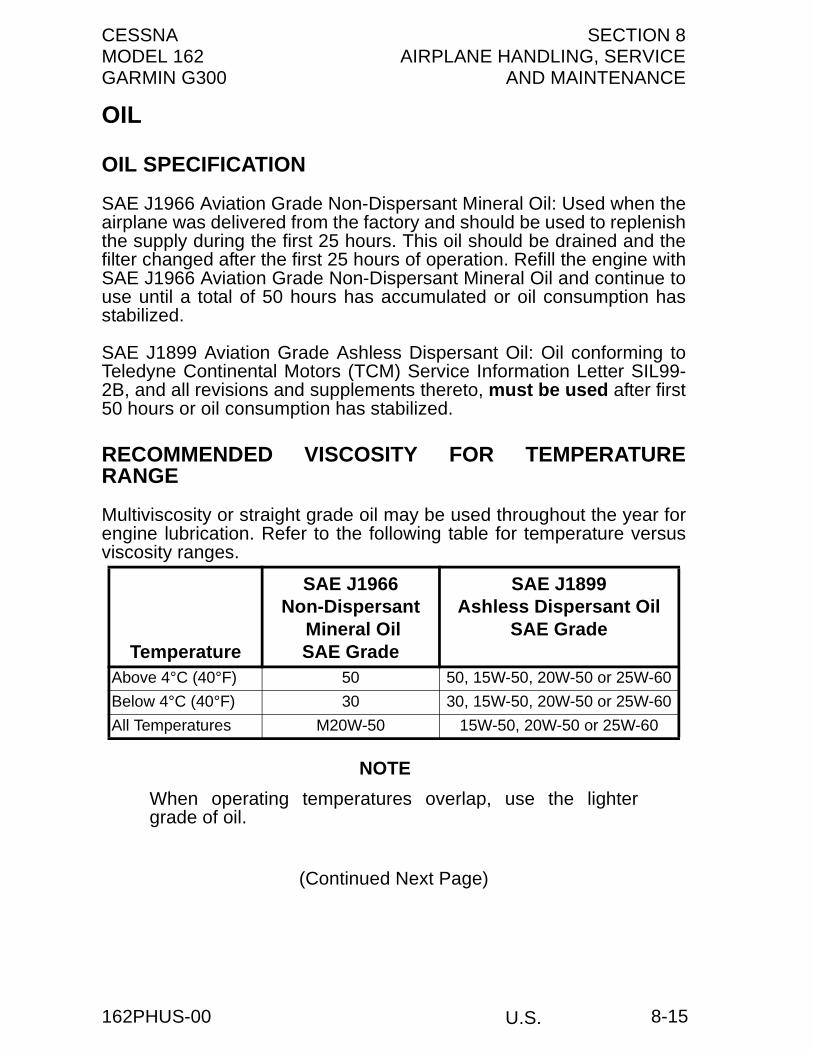
CESSNA SECTION 8MODEL 162 AIRPLANE HANDLING, SERVICEGARMIN G300 AND MAINTENANCE
OIL
OIL SPECIFICATION
SAE J1966 Aviation Grade Non-Dispersant Mineral Oil: Used when theairplane was delivered from the factory and should be used to replenishthe supply during the first 25 hours. This oil should be drained and thefilter changed after the first 25 hours of operation. Refill the engine withSAE J1966 Aviation Grade Non-Dispersant Mineral Oil and continue touse until a total of 50 hours has accumulated or oil consumption hasstabilized.
SAE J1899 Aviation Grade Ashless Dispersant Oil: Oil conforming toTeledyne Continental Motors (TCM) Service Information Letter SIL99-2B, and all revisions and supplements thereto, must be used after first50 hours or oil consumption has stabilized.
RECOMMENDED VISCOSITY FOR TEMPERATURERANGE
Multiviscosity or straight grade oil may be used throughout the year forengine lubrication. Refer to the following table for temperature versusviscosity ranges.
NOTE
When operating temperatures overlap, use the lightergrade of oil.
(Continued Next Page)
Temperature
SAE J1966Non-Dispersant
Mineral OilSAE Grade
SAE J1899Ashless Dispersant Oil
SAE Grade
Above 4°C (40°F) 50 50, 15W-50, 20W-50 or 25W-60
Below 4°C (40°F) 30 30, 15W-50, 20W-50 or 25W-60
All Temperatures M20W-50 15W-50, 20W-50 or 25W-60
U.S.162PHUS-00 8-15

SECTION 8 CESSNAAIRPLANE HANDLING, SERVICE MODEL 162AND MAINTENANCE GARMIN G300
OIL (Continued)
CAPACITY OF ENGINE SUMP
The engine has a total capacity of 5.5 U.S. quarts, with the oil filteraccounting for approximately 0.33 U.S. quarts of that total. The enginemust not be operated on less than 3.5 U.S. quarts (as measured by thedipstick). For extended flights, the engine should be filled to capacity.
OIL AND OIL FILTER CHANGE
After the first 25 hours of operation, drain the engine oil sump andreplace the filter. Refill sump with non-dispersant mineral oil and useuntil a total of 50 hours has accumulated or oil consumption hasstabilized; then change to ashless dispersant oil. Ashless dispersant oil(and oil filter) should be changed at time intervals set forth by theengine manufacturer.
NOTE
During the first 25 hour oil and filter change, a generalinspection of the overall engine compartment is required.Items which are not normally checked during a preflightinspection should be given special attention. Hoses, metallines and fittings should be inspected for signs of oil andfuel leaks, and checked for abrasions, chafing, security,proper routing and support, and evidence of deterioration.Inspect the intake and exhaust systems for cracks,evidence of leakage, and security of attachment. Enginecontrols and linkages should be checked for freedom ofmovement through their full range, security of attachmentand evidence of wear. Inspect wiring for security, chafing,burning, defective insulation, loose or broken terminals,heat deterioration, and corroded terminals. A periodiccheck of these items during subsequent servicingoperations is recommended.
U.S. 162PHUS-008-16

CESSNA SECTION 8MODEL 162 AIRPLANE HANDLING, SERVICEGARMIN G300 AND MAINTENANCE
FUEL
APPROVED FUEL GRADES (AND COLORS)100LL Grade Aviation Fuel (Blue)100 Grade Aviation Fuel (Green)
NOTE
Isopropyl alcohol or Diethylene Glycol Monomethyl Ether(DiEGME) may be added to the fuel supply in quantities notto exceed 1% (alcohol) or 0.15% (DiEGME) of total volume.Refer to Fuel Additives in later paragraphs for additionalinformation.
FUEL CAPACITYTotal Capacity . . . . . . . . . . . . . . . . . .25.46 U.S. GALLONS (96.34 l)Total Usable . . . . . . . . . . . . . . . . . . .24.00 U.S. GALLONS (90.82 l)Total Capacity Each Tank . . . . . . . . .12.73 U.S. GALLONS (48.17 l)Total Usable Each Tank. . . . . . . . . . .12.00 U.S. GALLONS (45.41 l)
NOTE
• To ensure maximum fuel capacity and minimizecrossfeeding when refueling, always park the airplane ina wings level, normal ground attitude. Refer to Figure 1-1 for normal ground attitude dimensions.
• The fuel filler assembly is equipped with indicator tabsfor 3/4, 1/2 and 1/4 fuel quantities.
• Maximum full capacity is indicated when fuel reaches theupper hole of the indicator tab. This fuel level allows forproper thermal expansion. Filling the fuel tank above theupper hole eliminates expansion space resulting in fuelventing overboard through the fuel vent.
(Continued Next Page)
U.S.162PHUS-00 8-17

SECTION 8 CESSNAAIRPLANE HANDLING, SERVICE MODEL 162AND MAINTENANCE GARMIN G300
FUEL (Continued)
FUEL ADDITIVES
Strict adherence to recommended preflight draining instructions ascalled for in Section 7 will eliminate any free water accumulations fromthe tank sumps. While small amounts of water may still remain insolution in the gasoline, it will normally be consumed and go unnoticedin the operation of the engine.
One exception to this can be encountered when operating under thecombined effect of: (1) use of certain fuels, with (2) high humidityconditions on the ground (3) followed by flight at high altitude and lowtemperature. Under these unusual conditions, small amounts of waterin solution can precipitate from the fuel stream and freeze in sufficientquantities to induce partial icing of the engine fuel system.
While these conditions are quite rare and will not normally pose aproblem to owners and operators, they do exist in certain areas of theworld and consequently must be dealt with, when encountered.
Therefore, to help alleviate the possibility of fuel icing occurring underthese unusual conditions, it is permissible to add isopropyl alcohol orDiethylene Glycol Monomethyl Ether (DiEGME) compound to the fuelsupply.
The introduction of alcohol or DiEGME compound into the fuel providestwo distinct effects: (1) it absorbs the dissolved water from the gasolineand (2) alcohol has a freezing temperature depressant effect.
NOTE
When using fuel additives, it must be remembered that thefinal goal is to obtain a correct fuel to additive ratio in thetank, and not just with fuel coming out of the refuelingnozzle. For example, adding 15 gallons of correctlyproportioned fuel to a tank which contains 20 gallons ofuntreated fuel will result in a lower than acceptableconcentration level to the 35 gallons of fuel which nowreside in the tank.
(Continued Next Page)
U.S. 162PHUS-008-18
CESSNA SECTION 8MODEL 162 AIRPLANE HANDLING, SERVICEGARMIN G300 AND MAINTENANCE
FUEL (Continued)
FUEL ADDITIVES (Continued)
Alcohol, if used, is to be blended with the fuel in a concentration of 1%by volume. Concentrations greater than 1% are not recommendedsince they can be detrimental to fuel tank materials.
The manner in which the alcohol is added to the fuel is significantbecause alcohol is most effective when it is completely dissolved in thefuel. To ensure proper mixing, the following is recommended:
1. For best results, the alcohol should be added during the fuelingoperation by pouring the alcohol directly on the fuel streamissuing from the fueling nozzle.
2. An alternate method that may be used is to premix the completealcohol dosage with some fuel in a separate clean container(approximately 2-3 gallon capacity) and then transferring thismixture to the tank prior to the fuel operation.
Diethylene Glycol Monomethyl Ether (DiEGME) compound must becarefully mixed with the fuel in concentrations between 0.10%(minimum) and 0.15% (maximum) of total fuel volume. Refer to Figure8-1 for a DiEGME-to-fuel mixing chart.
WARNING
ANTI-ICING ADDITIVE IS DANGEROUS TO HEALTHWHEN BREATHED AND/OR ABSORBED INTO THESKIN.
CAUTION
MIXING OF DIEGME WITH FUEL IS EXTREMELYIMPORTANT. A CONCENTRATION IN EXCESS OF THATRECOMMENDED (0.15% BY VOLUME MAXIMUM) MAYRESULT IN DETRIMENTAL EFFECTS TO THE FUELTANK AND SEALANT, AND DAMAGE TO O-RINGS ANDSEALS USED IN THE FUEL SYSTEM AND ENGINECOMPONENTS. A CONCENTRATION OF LESS THANTHAT RECOMMENDED (0.10% BY TOTAL VOLUMEMINIMUM) WILL RESULT IN INEFFECTIVE TREATMENT.USE ONLY BLENDING EQUIPMENT THAT ISRECOMMENDED BY THE MANUFACTURER TO OBTAINPROPER PROPORTIONING.
(Continued Next Page)
U.S.162PHUS-01 8-19

SECTION 8 CESSNAAIRPLANE HANDLING, SERVICE MODEL 162AND MAINTENANCE GARMIN G300
FUEL (Continued)
FUEL ADDITIVES (Continued)
FUEL MIXING RATIO
Prolonged storage of the airplane will result in a water buildup in thefuel which leeches out the additive. An indication of this is when anexcessive amount of water accumulates in the fuel tank sumps. Theconcentration can be checked using a differential refractometer. It isimperative that the technical manual for the differential refractometer befollowed explicitly when checking the additive concentration.
(Continued Next Page)
Figure 8-1*
U.S. 162PHUS-018-20

CESSNA SECTION 8MODEL 162 AIRPLANE HANDLING, SERVICEGARMIN G300 AND MAINTENANCE
FUEL (Continued)
FUEL CONTAMINATION
Fuel contamination is usually the result of foreign material present inthe fuel system, and may consist of water, rust, sand, dirt, microbes orbacterial growth. In addition, additives that are not compatible with fuelor fuel system components can cause the fuel to becomecontaminated.
Before each flight and after each refueling, use a clear sampler cup anddrain at least a cupful of fuel from each fuel tank drain location and fromthe fuel strainer quick drain valve to determine if contaminants arepresent, and to ensure the airplane has been fueled with the propergrade of fuel.
If contamination is detected, drain all fuel drain points again, includingthe fuel strainer and fuel sump valve, and then gently rock the wingsand lower the tail to the ground to move any additional contaminants tothe sampling points. Take repeated samples from all fuel drain pointsuntil all contamination has been removed. If, after repeated sampling,evidence of contamination still exists, the airplane should not be flown.Tanks should be drained and system purged by qualified maintenancepersonnel. All evidence of contamination must be removed beforefurther flight. If the airplane has been serviced with the improper fuelgrade, defuel completely and refuel with the correct grade. Do not flythe airplane with contaminated or unapproved fuel.
In addition, Owners/Operators who are not acquainted with a particularfixed base operator should be assured that the fuel supply has beenchecked for contamination and is properly filtered before allowing theairplane to be serviced. Fuel tanks should be kept full between flights,provided weight and balance considerations will permit, to reduce thepossibility of water condensing on the walls of partially filled tanks.
To further reduce the possibility of contaminated fuel, routinemaintenance of the fuel system should be performed in accordancewith the airplane Maintenance Manual. Only the proper fuel, asrecommended in this POH, should be used, and fuel additives shouldnot be used unless approved by Cessna and the Federal AviationAdministration.
U.S.162PHUS-01 8-21

SECTION 8 CESSNAAIRPLANE HANDLING, SERVICE MODEL 162AND MAINTENANCE GARMIN G300
LANDING GEAR
Consult the following table for servicing information on the landing gear.
CLEANING AND CARE
WINDSHIELD AND WINDOWS
The plastic windshield and windows should be cleaned with an airplanewindshield cleaner. Apply the cleaner sparingly with soft cloths, and rubwith moderate pressure until all dirt, oil scum and bug stains areremoved. Allow the cleaner to dry, then wipe it off with soft flannelcloths. The inside of the windshield should be cleaned with a anti-fogcleaning agent.
CAUTION
NEVER USE GASOLINE, BENZENE, ALCOHOL,ACETONE, FIRE EXTINGUISHER, ANTI-ICE FLUID,LACQUER THINNER OR GLASS CLEANER TO CLEANTHE PLASTIC. THESE MATERIALS WILL ATTACK THEPLASTIC AND MAY CAUSE IT TO CRAZE.
If a windshield cleaner is not available, the plastic can be cleaned withsoft cloths moistened with Stoddard solvent to remove oil and grease.Follow by carefully washing with a mild detergent and plenty of water.Rinse thoroughly, then dry with a clean moist chamois.
Do not rub the plastic with a dry cloth since this builds up anelectrostatic charge which attracts dust. Waxing with a goodcommercial wax will finish the cleaning job. A thin, even coat of wax,polished out by hand with clean soft flannel cloths, will fill in minorscratches and help prevent further scratching.
Do not use a canvas cover on the windshield unless freezing rain orsleet is anticipated since the cover may scratch the plastic surface.
(Continued Next Page)
COMPONENT SERVICING CRITERIA
Nose Wheel (4.00-5, 8-Ply Rated Tire) 38.0 PSI +/- 2.0 PSI
Main Wheel (5.00-5, 4-Ply Rated Tire) 30.0 PSI +/- 2.0 PSI
Brakes MIL-H-5606
U.S. 162PHUS-018-22

CESSNA SECTION 8MODEL 162 AIRPLANE HANDLING, SERVICEGARMIN G300 AND MAINTENANCE
CLEANING AND CARE (Continued)
PAINTED SURFACES
The painted exterior surfaces of your new Cessna have a durable, longlasting finish.
Generally, the painted surfaces can be kept bright by washing withwater and mild soap, followed by a rinse with water and drying withcloths or a chamois. Remove stubborn oil and grease with a clothmoistened with Stoddard solvent. Take special care to make sure thatthe exterior graphics are not touched by the solvent. For complete careof exterior graphics, refer to the Maintenance Manual.
CAUTION
HARSH OR ABRASIVE SOAPS OR DETERGENTSWHICH CAUSE CORROSION OR SCRATCHES SHOULDNEVER BE USED ON THE PAINTED ALUMINUMSTRUCTURE.
To seal any minor surface chips or scratches and protect againstcorrosion, the airplane should be waxed regularly with a goodautomotive wax applied in accordance with the manufacturer'sinstructions. If the airplane is operated in a seacoast or other salt waterenvironment, it must be washed and waxed more frequently to assureadequate protection. Special care should be taken to seal around rivetheads and skin laps, which are the areas most susceptible to corrosion.A heavier coating of wax on the leading edges of the wings and tail andon the cowl nose cap and propeller spinner will help reduce theabrasion encountered in these areas. Reapplication of wax willgenerally be necessary after cleaning with soap solution or afterchemical deicing operations.
When the airplane is parked outside in cold climates and it is necessaryto remove ice before flight, care should be taken to protect the paintedsurfaces during ice removal with chemical liquids. Isopropyl alcohol willsatisfactorily remove ice accumulations without damaging the paint.However, keep the isopropyl alcohol away from the windshield andcabin windows since it will attack the plastic and may cause it to craze.
(Continued Next Page)
U.S.162PHUS-01 8-23
SECTION 8 CESSNAAIRPLANE HANDLING, SERVICE MODEL 162AND MAINTENANCE GARMIN G300
CLEANING AND CARE (Continued)
PROPELLER CARE
Preflight inspection should include inspection of the propeller blades fornicks and scratches. Small nicks on the propeller, particularly near thetips and on the leading edges, should be monitored.
WARNING
OPERATION WITH NICKS OR SCRATCHES IN THELEADING EDGE GREATER THAN 0.125 INCHES MAYRESULT IN CRACKS OR FAILURE OF THEPROPELLER BLADE.
ENGINE CARE
The engine may be cleaned, using a suitable solvent, in accordancewith instructions in the Maintenance Manual. Most efficient cleaning isdone using a spray type cleaner. Before spray cleaning, ensure thatprotection is afforded for components which might be adverselyaffected by the solvent. Refer to the airplane Maintenance Manual forproper lubrication of controls and components after engine cleaning.The induction air filter should be replaced when its condition warrants,not to exceed 500 hours.
(Continued Next Page)
U.S. 162PHUS-01
8-24
CESSNA SECTION 8MODEL 162 AIRPLANE HANDLING, SERVICEGARMIN G300 AND MAINTENANCE
CLEANING AND CARE (Continued)
INTERIOR CARE
To remove dust and loose dirt from the upholstery and interior, cleanthe interior regularly with a vacuum cleaner.
Blot up any spilled liquid promptly with cleansing tissue or rags. Do notpat the spot; press the blotting material firmly and hold it for severalseconds. Continue blotting until no more liquid is taken up. Scrape offsticky materials with a dull knife, then spot clean the area.
Oily spots may be cleaned with household spot removers, usedsparingly. Before using any solvent, read the instructions on thecontainer and test it on an obscure place on the fabric to be cleaned.Never saturate the fabric with a volatile solvent; it may damage thepadding and backing materials.
Soiled upholstery may be cleaned with foam type detergent, usedaccording to the manufacturer's instructions. To minimize wetting thefabric, keep the foam as dry as possible and remove it with a vacuumcleaner.
CAUTION
HARSH OR ABRASIVE SOAPS OR DETERGENTSWHICH CAUSE CORROSION OR SCRATCHES SHOULDNEVER BE USED ON THE PAINTED ALUMINUMSTRUCTURE.
For complete information related to interior cleaning, refer to theMaintenance Manual.
AVIONICS CARE
The Garmin G300 and avionics displays have an anti-reflective coatingthat is very sensitive to skin oils, waxes, ammonia, and abrasivecleaners. Clean the displays as described in the G300 Pilot’s Guide.
U.S.162PHUS-01 8-25/8-26


CESSNA SECTION 9MODEL 162 PLACARDS AND MARKINGSGARMIN G300
PLACARDS AND MARKINGS
TABLE OF CONTENTSPage
Airspeed Indicator Markings . . . . . . . . . . . . . . . . . . . . . . . . . . . . . . .9-3Powerplant Instrument Markings . . . . . . . . . . . . . . . . . . . . . . . . . . . .9-4Placards. . . . . . . . . . . . . . . . . . . . . . . . . . . . . . . . . . . . . . . . . . . . . . .9-5
U.S.162PHUS-00 9-1/9-2


CESSNA SECTION 9MODEL 162 PLACARDS AND MARKINGSGARMIN G300
AIRSPEED INDICATOR MARKINGSAirspeed indicator markings and their color code significance areshown in Figure 9-2.
AIRSPEED INDICATOR MARKINGSMARKING KIAS VALUE OR
RANGE SIGNIFICANCE
Red Band <37 Low airspeed warning.
White Band 37 - 70 Full Flap Operating Range. Lower limit ismaximum weight VSO in landing configuration.Upper limit is maximum speed permissible withflaps extended.
Green Band 41 - 124 Normal Operating Range. Lower limit ismaximum weight VS1 at most forward C.G.with flaps retracted. Upper limit is maximumstructural cruising speed.
Yellow Band
124 - 148 Operations must be conducted with cautionand only in smooth air.
Red Line >149 Maximum speed for all operations.
Flaps 25°Tick Mark
85 Maximum Flaps 25° Operation
Flaps 10°Tick Mark
100 Maximum Flaps 10° Operation
VxTick Mark
57 Best Angle of Climb Air Speed
VyTick Mark
62 Best Rate of Climb Air Speed
Figure 9-1
U.S.162PHUS-01 9-3
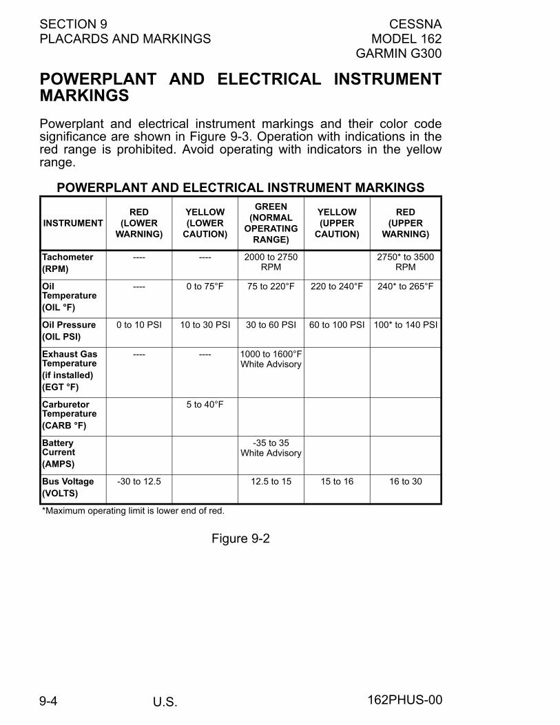
SECTION 9 CESSNAPLACARDS AND MARKINGS MODEL 162
GARMIN G300
POWERPLANT AND ELECTRICAL INSTRUMENTMARKINGSPowerplant and electrical instrument markings and their color codesignificance are shown in Figure 9-3. Operation with indications in thered range is prohibited. Avoid operating with indicators in the yellowrange.
POWERPLANT AND ELECTRICAL INSTRUMENT MARKINGS
Figure 9-2
INSTRUMENTRED
(LOWERWARNING)
YELLOW(LOWER
CAUTION)
GREEN (NORMAL
OPERATING RANGE)
YELLOW(UPPER
CAUTION)
RED(UPPER
WARNING)
Tachometer(RPM)
---- ---- 2000 to 2750RPM
2750* to 3500 RPM
OilTemperature(OIL °F)
---- 0 to 75°F 75 to 220°F 220 to 240°F 240* to 265°F
Oil Pressure(OIL PSI)
0 to 10 PSI 10 to 30 PSI 30 to 60 PSI 60 to 100 PSI 100* to 140 PSI
Exhaust GasTemperature(if installed)(EGT °F)
---- ---- 1000 to 1600°FWhite Advisory
CarburetorTemperature(CARB °F)
5 to 40°F
BatteryCurrent(AMPS)
-35 to 35White Advisory
Bus Voltage(VOLTS)
-30 to 12.5 12.5 to 15 15 to 16 16 to 30
*Maximum operating limit is lower end of red.
U.S. 162PHUS-009-4

CESSNA SECTION 9MODEL 162 PLACARDS AND MARKINGSGARMIN G300
PLACARDSThe following information must be displayed in the form of composite orindividual placards.
1. In full view of the pilot: (The DAY-NIGHT-VFR entry, shown onthe example below, will vary with installed equipment):
2. On control lock:
3. Silk-screened on left instrument panel above magnetos switch:
(Continued Next Page)
The markings and placards installed in this airplane contain operatinglimitations which must be complied with when operating this airplane.Other operating limitations which must be complied with whenoperating this airplane in this category are contained in the Pilot’sOperating Handbook.
No acrobatic maneuvers, including spins, are approved.
Flight into known icing conditions prohibited.
This airplane is approved for the following flight operations as of the date of original airworthiness certificate:
DAY - NIGHT - VFR
TAKEOFF PROHIBITED WITH LESS THAN 1/4 FUELMINTO
U.S.162PHUS-00 9-5

SECTION 9 CESSNAPLACARDS AND MARKINGS MODEL 162
GARMIN G300
PLACARDS (Continued)4. Silk-screened on the lower left instrument panel:
WARNINGAssure that all contaminants,including water, are removedfrom fuel and fuel systemsbefore flight. Failure to assurecontaminant free fuel and heedall safety instructions andowner advisories prior to flightcan result in bodily injury or death.
5. Silk-screened on the upper left instrument panel:
NO INTENTIONAL SPINS
6. On the instrument panel directly above the PFD:MAXIMUM OPERATING MANEUVERING SPEED: 89 KIASDESIGN MANEUVERING SPEED: 102 KIAS
7. Silk-screened on the upper right instrument panel:
8. Silk-screened on the right instrument panel:
This aircraft wasmanufactured inaccordance with LightSport Aircraft airworthinessstandards and does not conformto standard category airworthinessrequirements.
(Continued Next Page)
U.S. 162PHUS-029-6

CESSNA SECTION 9MODEL 162 PLACARDS AND MARKINGSGARMIN G300
PLACARDS (Continued)
9. On the right side of the baggage compartment below thewindow:
10. Near both fuel tank filler cap:
11. On the engine oil access door:
(Continued Next Page)
U.S.162PHUS-01 9-7

SECTION 9 CESSNAPLACARDS AND MARKINGS MODEL 162
GARMIN G300
PLACARDS (Continued)12. On firewall adjacent to battery box and second placard on
external power receptacle door if external power receptacleoption is installed:
13. Located on both left and right fuel sight tubes:
U.S. 162PHUS-019-8

CESSNA SECTION 10MODEL 162 SUPPLEMENTSGARMIN G300
U.S.
SUPPLEMENTS
INTRODUCTION
The supplements in this section contain amended operating limitations,operating procedures, performance data and other necessaryinformation for airplanes conducting special operations for bothstandard and optional equipment installed in the airplane. Operatorsshould refer to each supplement to ensure that all limitations andprocedures appropriate for their airplane are observed.
A Cessna Approved Log Of Approved Supplements is provided forconvenience only. This log is a numerical list of all Cessna Approvedsupplements applicable to this airplane by name, supplement numberand revision level. This log should be used as a checklist to ensure allapplicable supplements have been placed in the Pilot's OperatingHandbook (POH). Supplements for both standard and installed optionalequipment must be maintained to the latest revision. Thosesupplements applicable to optional equipment which is not installed inthe airplane, do not have to be retained.
Each individual supplement contains its own Log of Effective Pages.This log lists the page number and revision level of every page in thesupplement. The log also lists the dates on which revisions to thesupplement occurred. Supplement page numbers will include an S andthe supplement number preceding the page number.
The part number of the supplement provides information on therevision level. Refer to the following example:
162PHUS -S1 -00Revision Level of Supplement
Supplement NumberCessna 162 U.S. Pilot’s Operating Handbook (Serials 16200001 and On)
162PHUS-00 10-1/10-2

CESSNA SECTION 10MODEL 162 SUPPLEMENTSGARMIN G300
U.S.
LOG OF APPROVED SUPPLEMENTS
NOTEIt is the airplane owner's responsibility to make sure that heor she has the latest revision to each supplement of aPilot's Operating Handbook, and the latest issued "Log OfApproved Supplements". This "Log Of ApprovedSupplements" was the latest version as of the date it wasshipped by Cessna; however, some changes may haveoccurred, and the owner should verify this is the latest,most up-to-date version by contacting Cessna CustomerService at (316) 517-5800.
SupplementNumber
Name RevisionLevel
EquipmentInstalled
1 Ameri-King AK-450 EmergencyLocator Transmitter (ELT)
0
2 Ameri-King AK-451 EmergencyLocator Transmitter (ELT) 0
3 PS Engineering PM3000 IntercomSystem 0
4 Reserved5 Reserved6 Garmin GTX 327 Transponder 07 Garmin SL 40 VHF Comm
Transceiver 0
19 November 2009162PHUSLOG-01
Log 1/Log 2

U.S.
CESSNA MODEL 162
Serials 16200001 and On
SUPPLEMENT 1
AMERI-KING AK-450EMERGENCY LOCATOR TRANSMITTER (ELT)
This supplement must be inserted into Section 10 of the Pilot's OperatingHandbook and Airplane Flight Manual when the Ameri-King AK-450 EmergencyLocator Transmitter (ELT) is installed.
SERIAL NO.
REGISTRATION NO.
162PHUS-S1-00
COPYRIGHT © 2009CESSNA AIRCRAFT COMPANY
WICHITA, KANSAS, USA
S1-1
2 NOVEMBER 2009
SECTION 10 - SUPPLEMENTS CESSNASUPPLEMENT 1 MODEL 162
GARMIN G300
U.S.
SUPPLEMENT 1
AMERI-KING AK-450 EMERGENCY LOCATORTRANSMITTER (ELT)
Use the Log of Effective Pages to determine the current status of thissupplement.
Pages affected by the current revision are indicated by an asterisk (*)preceding the page number.
LOG OF EFFECTIVE PAGES
Supplement Status Date
Original Issue 2 November 2009
PageNumber
PageStatus
RevisionNumber
S1-1 thru S1-8 Original 0
162PHUS-S1-00S1-2

CESSNA SECTION 10 - SUPPLEMENTSMODEL 162 SUPPLEMENT 1GARMIN G300
U.S.
SERVICE BULLETIN CONFIGURATION LIST
The following is a list of Service Bulletins that are applicable to theoperation of the airplane, and have been incorporated into thissupplement. This list contains only those Service Bulletins that arecurrently active.
Number Title
Airplane Serial
Effectivity
Revision
Incorporated
Incorporated
in Airplane
162PHUS-S1-00 S1-3
SECTION 10 - SUPPLEMENTS CESSNASUPPLEMENT 1 MODEL 162
GARMIN G300
U.S.
AMERI-KING AK-450 EMERGENCY LOCATORTRANSMITTER (ELT)GENERAL
The Ameri-King AK-450 Emergency Locator Transmitter (ELT)installation uses a solid-state 2-frequency transmitter, 121.5 and 243.0MHz, powered by six “D” cell alkaline batteries (Duracell MN 1300 ormanufactures’ approved equivalent). The AK-450 is also equipped withan panel-mounted remote switch assembly and an external antennamounted on the top of the tailcone. The remote switch assembly isinstalled on the right instrument panel and receives power from a singlelithium cell battery (Duracell DL1/3 NB or manufactures’ approvedequivalent).
CAUTION
USE OF NON-APPROVED BATTERIES WILL VOIDMANUFACTURERS’ TSO-91A AND PRODUCTWARRANTIES.
The remote switch controls ELT operating modes from the flight crewstation. When the ELT main unit control switch is set to the ARMposition, the transmitter is energized only when the internal "G” switchsenses longitudinal inertia forces per TSO-C91a/TSO-C126. Inemergency situations the transmitter can also be immediatelyenergized by pressing the ON switch located within the remote switchassembly.
The AK-450 transmitter unit is located in the tailcone behind thebaggage area. On the ELT transmitter unit is a panel containing an ON/OFF/ARM switch and a transmitter warning light.
The ELT installation uses two different warnings to tell the pilot whenthe ELT is energized. The aural warning is an unusual sound that iseasily heard by the pilot. The visual warning is a steady RED lightlocated within the panel-mounted remote switch that shows the pilotthat the ELT has been activated.
When the AK-450 is energized, the ELT transmits the standard swepttone signal on the international VHF frequency of 121.5 MHz and UHFfrequency of 243.0 MHz until battery power is gone. The 121.5 MHzsignal is mainly used to pinpoint the beacon during search and rescueoperations, and is monitored by general aviation, commercial aircraft,and government agencies.
(Continued Next Page)
162PHUS-S1-00S1-4

CESSNA SECTION 10 - SUPPLEMENTSMODEL 162 SUPPLEMENT 1GARMIN G300
U.S.
AMERI-KING AK-450 ELT MAIN CONTROL PANEL
1. ANT - Antenna receptacle connects to the antenna mounted ontop of tailcone.
2. REMOTE - Remote cable jack connects to the ELT remoteswitch assembly located on the upper right instrument panel.
3. RESET - Reset button deactivates transmitter.4. TRANSMITTER WARNING LIGHT - Light comes on RED to
indicate the transmitter is transmitting a distress signal.5. ELT PANEL SWITCH (3-Position Toggle Switch):
a. ON - Activates transmitter instantly. The ON positionbypasses the automatic activation switch. The RED warninglight on ELT main control panel and the remote panel-mounted switch assembly will come on and aural warningwill sound.
b. OFF - Turns OFF transmitter for handling, following rescueand to reset the automatic activation function if unable toreset using the remote panel-mounted reset button.
c. ARM - ARMS transmitter for automatic activation if “G”switch senses a predetermined deceleration level.
162PHUS-S1-00 S1-5

SECTION 10 - SUPPLEMENTS CESSNASUPPLEMENT 1 MODEL 162
GARMIN G300
U.S.
AMERI-KING AK-450 ELT REMOTE SWITCH PANEL
1. ON Button - Remotely activates the transmitter for testing oremergency situations. The RED warning light comes on toindicate that the transmitter is transmitting a distress signal.
2. ON Light - Transmitter warning light comes on RED to indicatethe transmitter is transmitting a distress signal.
3. RESET - Reset button deactivates or de-energizes thetransmitter.
OPERATING LIMITATIONS
There are no additional airplane operating limitations when the Ameri-King AK-450 ELT is installed.
Refer to 14 CFR 91.207 for ELT inspection requirements. The AK-450must be inspected and tested by an approved technician using thecorrect test equipment under the appropriate civil aviation authoritiesapproved conditions.
162PHUS-S1-00S1-6

CESSNA SECTION 10 - SUPPLEMENTSMODEL 162 SUPPLEMENT 1GARMIN G300
U.S.
EMERGENCY PROCEDURES
If a forced landing is necessary, press the ON switch within the remoteswitch panel before landing. This is very important in remote ormountainous terrain. The RED warning light will illuminate and the auralwarning will be heard.
After a landing when search and rescue aid is needed, use the ELT asfollows:
NOTE
The ELT remote switch assembly could be inoperative ifdamaged during a forced landing. If inoperative, the inertia“G” switch will activate automatically. However, to turn theELT OFF and ON again requires manual switching of theELT main control panel switch which is located on the ELTtransmitter unit located in the tailcone.
1. MAKE SURE THE ELT IS ENERGIZED:a. If the RED warning light in the remote switch panel is not
illuminated, press the ON switch within the remote switchpanel to energize the ELT transmitter.
b. Listen for the aural warning. If the COM radio(s) operate andcan be energized safely (no threat of fire or explosion),energize a COM radio and set the frequency to 121.5 MHz.The ELT tone should be heard on the COM radio if the ELTis working correctly. When done, de-energize the COMradio(s) to conserve the airplane battery power.
c. Make sure that nothing is touching or blocking the ELTantenna.
2. AFTER RESCUE - Press the RESET button in the remoteswitch panel to de-energize the ELT. If the remote switch doesnot de-energize the ELT, press the RESET button on the ELTmain control panel located in the tailcone.
162PHUS-S1-00 S1-7

SECTION 10 - SUPPLEMENTS CESSNASUPPLEMENT 1 MODEL 162
GARMIN G300
U.S.
NORMAL PROCEDURES
When operating in a remote area or over hazardous terrain, it isrecommended that the ELT be inspected by an approved technicianmore frequently than required by 14 CFR 91.207.
NORMAL OPERATION
Normal operation of the AK-450 ELT from the flight crew station is onlyto de-energize and arm the ELT after it has been accidentally energized(no emergency).
For normal operation of the AK-450ELT, the main switch on the ELTmain control panel must be set to the ARM position. You cannot disarmor disable the ELT transmitter from the cockpit; you can only deactivatethe ELT after it has been activated.
The ELT can be energized by a lightning strike or hard landing. If theRED light, within the remote switch panel, is illuminated and the auralwarning is heard, the ELT is energized. Check for the emergency signalon a COM radio set to 121.5 MHz. To stop the transmissions, press theRESET button on the remote switch panel to de-energize the ELT. Tellthe nearest Air Traffic Control facility about the accidentaltransmissions as soon as possible to hold search and rescue work to aminimum.
PERFORMANCE
There is no change to the airplane performance when the Ameri-KingAK-450 ELT is installed.
162PHUS-S1-00S1-8

U.S.
CESSNA MODEL 162
Serials 16200001 and On
SUPPLEMENT 2AMERI-KING AK-451
EMERGENCY LOCATOR TRANSMITTER (ELT)
This supplement must be inserted into Section 10 of the Pilot's OperatingHandbook and Airplane Flight Manual when the Ameri-King AK-451 EmergencyLocator Transmitter (ELT) is installed.
SERIAL NO.
REGISTRATION NO.
162PHUS-S2-00
COPYRIGHT © 2009CESSNA AIRCRAFT COMPANY
WICHITA, KANSAS, USA
S2-1
19 NOVEMBER 2009

SECTION 10 - SUPPLEMENTS CESSNASUPPLEMENT 2 MODEL 162
GARMIN G300
U.S.
SUPPLEMENT 2
AMERI-KING AK-451 EMERGENCY LOCATORTRANSMITTER (ELT)
Use the Log of Effective Pages to determine the current status of thissupplement.
Pages affected by the current revision are indicated by an asterisk (*)preceding the page number.
LOG OF EFFECTIVE PAGES
Supplement Status DateOriginal Issue 19 November 2009
PageNumber
PageStatus
RevisionNumber
S2-1 thru S2-9/S2-10 Original 0
162PHUS-S2-00S2-2
CESSNA SECTION 10 - SUPPLEMENTSMODEL 162 SUPPLEMENT 2GARMIN G300
U.S.
SERVICE BULLETIN CONFIGURATION LISTThe following is a list of Service Bulletins that are applicable to theoperation of the airplane, and have been incorporated into thissupplement. This list contains only those Service Bulletins that arecurrently active.
Number TitleAirplane SerialEffectivity
RevisionIncorporated
Incorporatedin Airplane
162PHUS-S2-00 S2-3

SECTION 10 - SUPPLEMENTS CESSNASUPPLEMENT 2 MODEL 162
GARMIN G300
U.S.
AMERI-KING AK-451 EMERGENCY LOCATORTRANSMITTER (ELT)
GENERALThe Ameri-King AK-451 Emergency Locator Transmitter (ELT)installation uses a solid-state 3-frequency transmitter, 121.5, 243.0 and406.0 MHz, powered by an internal lithium battery. The AK-451 is alsoequipped with a panel-mounted remote switch assembly and anexternal antenna mounted on the top of the tailcone. The remote switchassembly is installed on the right instrument panel and receives powerfrom a single lithium cell battery (Duracell DL1/3 NB or manufactures’approved equivalent).
CAUTIONUSE OF NON-APPROVED BATTERIES WILL VOIDMANUFACTURERS’ TSO-91A AND PRODUCTWARRANTIES.
The remote switch controls ELT operating modes from the flight crewstation. When the ELT main unit control switch is set to the ARMposition, the transmitter is energized only when the internal "G” switchsenses longitudinal inertia forces per TSO-C91a/TSO-C126. Inemergency situations the transmitter can also be immediatelyenergized by pressing the ON switch located within the remote switchassembly.
The AK-451 transmitter unit is located in the tailcone behind thebaggage area. On the ELT transmitter unit is a panel containing an ON/OFF/ARM switch and a transmitter ON light.
The ELT installation uses two different warnings to tell the pilot whenthe ELT is energized. The aural warning is an unusual sound that iseasily heard by the pilot. The visual warning is a flashing GREEN ONlight located within the panel-mounted remote switch that shows thepilot that the ELT has been activated.
(Continued Next Page)
162PHUS-S2-00S2-4

CESSNA SECTION 10 - SUPPLEMENTSMODEL 162 SUPPLEMENT 2GARMIN G300
U.S.
GENERAL (Continued)
When the AK-451 is energized, the ELT transmits the standard swepttone signal on the international VHF frequency of 121.5 MHz and UHFfrequency of 243.0 MHz until battery power is gone. The 121.5 MHzsignal is mainly used to pinpoint the beacon during search and rescueoperations, and is monitored by general aviation, commercial aircraft,and government agencies.
In addition, for the first 24 hours of the ELT being energized, a 406.028MHz signal is transmitted at 50 second intervals. This transmissionlasts 520 milliseconds and contains identification data programmed intothe ELT and is received by COSPAS/SARSAT satellites. Thetransmitted data may include the Aircraft ID, ELT Serial Number,Country Code, and COSPAS/SARSAT ID.
162PHUS-S2-00 S2-5

SECTION 10 - SUPPLEMENTS CESSNASUPPLEMENT 2 MODEL 162
GARMIN G300
U.S.
GENERAL (Continued)
AMERI-KING AK-451 ELT MAIN CONTROL PANEL
1. ANT - Antenna receptacle connects to the antenna mounted ontop of tailcone.
2. REMOTE - Remote cable jack connects to the ELT remoteswitch assembly located on the upper right instrument panel.
3. RESET - Reset button deactivates transmitter.4. TRANSMITTER ON LIGHT - Light flashes GREEN to indicate
the transmitter is transmitting a distress signal.5. ELT PANEL SWITCH (3-Position Toggle Switch):
a. ON - Activates transmitter instantly. The ON positionbypasses the automatic activation switch. The GREEN ONlight on ELT main control panel and the remote panel-mounted switch assembly will flash and aural warning willsound, at a rate of 1 second ON, 4 seconds OFF.
b. OFF - Turns OFF transmitter for handling, following rescueand to reset the automatic activation function if unable toreset using the remote panel-mounted reset button.
c. ARM - ARMS transmitter for automatic activation if “G”switch senses a predetermined deceleration level.
162PHUS-S2-00S2-6

CESSNA SECTION 10 - SUPPLEMENTSMODEL 162 SUPPLEMENT 2GARMIN G300
U.S.
GENERAL (Continued)
AMERI-KING AK-451 ELT REMOTE SWITCH PANEL
1. ON Button - Remotely activates the transmitter for testing oremergency situations. The GREEN ON light flashes to indicatethe ELT transmitter is transmitting a distress signal.
2. ON Light - Transmitter ON light flashes GREEN to indicate thetransmitter is transmitting a distress signal.
3. RESET - Reset button deactivates or de-energizes thetransmitter.
OPERATING LIMITATIONSThere are no additional airplane operating limitations when the Ameri-King AK-451 ELT is installed.
The airplane owner or operator must register the AK-451 ELT with theapplicable civil aviation authority before use to make sure that theidentification code transmitted by the ELT is in the COSPAS/SARSATdatabase. Refer to www.cospas-sarsat.org for registration information.
Refer to 14 CFR 91.207 for ELT inspection requirements. The AK-451must be inspected and tested by an approved technician using thecorrect test equipment under the appropriate civil aviation authoritiesapproved conditions.
162PHUS-S2-00 S2-7

SECTION 10 - SUPPLEMENTS CESSNASUPPLEMENT 2 MODEL 162
GARMIN G300
U.S.
EMERGENCY PROCEDURESIf a forced landing is necessary, press the ON switch within the remoteswitch panel before landing. This is very important in remote ormountainous terrain. The GREEN ON light will flash and the auralwarning will be heard.
After a landing when search and rescue aid is needed, use the ELT asfollows:
NOTEThe ELT remote switch assembly could be inoperative ifdamaged during a forced landing. If inoperative, the inertia“G” switch will activate automatically. However, to turn theELT OFF and ON again requires manual switching of theELT main control panel switch which is located on the ELTtransmitter unit located in the tailcone.
1. MAKE SURE THE ELT IS ENERGIZED:a. If the GREEN ON light in the remote switch panel is not
flashing, press the ON switch within the remote switch panelto energize the ELT transmitter.
b. Listen for the aural warning. If the COM radio(s) operate andcan be energized safely (no threat of fire or explosion),energize a COM radio and set the frequency to 121.5 MHz.The ELT tone should be heard on the COM radio if the ELTis working correctly. When done, de-energize the COMradio(s) to conserve the airplane battery power.
c. Make sure that nothing is touching or blocking the ELTantenna.
2. AFTER RESCUE - Press the RESET button in the remoteswitch panel to de-energize the ELT. If the remote switch doesnot de-energize the ELT, press the RESET button on the ELTmain control panel located in the tailcone.
162PHUS-S2-00S2-8

CESSNA SECTION 10 - SUPPLEMENTSMODEL 162 SUPPLEMENT 2GARMIN G300
U.S.
NORMAL PROCEDURESWhen operating in a remote area or over hazardous terrain, it isrecommended that the ELT be inspected by an approved technicianmore frequently than required by 14 CFR 91.207.
NORMAL OPERATION
Normal operation of the AK-451 ELT from the flight crew station is onlyto de-energize the ELT after it has been accidentally energized (noemergency).
For normal operation of the AK-451 ELT, the main switch on the ELTmain control panel must be set to the ARM position. You cannot disarmor disable the ELT transmitter from the cockpit; you can only deactivatethe ELT after it has been activated.
The ELT can be energized by a lightning strike or hard landing. If theGREEN ON light, within the remote switch panel, is flashing and theaural warning is heard, the ELT is energized. Check for the emergencysignal on a COM radio set to 121.5 MHz. To stop the transmissions,press the RESET button on the remote switch panel to de-energize theELT. Tell the nearest Air Traffic Control facility about the accidentaltransmissions as soon as possible to hold search and rescue work to aminimum.
PERFORMANCEThere is no change to the airplane performance when the Ameri-KingAK-451 ELT is installed.
162PHUS-S2-00 S2-9/S2-10


U.S.
CESSNA MODEL 162
Serials 16200001 and On
SUPPLEMENT 3PS ENGINEERING
PM3000 INTERCOM SYSTEM
This supplement must be inserted into Section 10 of the Pilot's OperatingHandbook and Airplane Flight Manual when the PS Engineering PM3000 IntercomSystem is installed.
SERIAL NO.
REGISTRATION NO.
162PHUS-S3-00
COPYRIGHT © 2009CESSNA AIRCRAFT COMPANY
WICHITA, KANSAS, USA
S3-1
19 NOVEMBER 2009
SECTION 10 - SUPPLEMENTS CESSNASUPPLEMENT 3 MODEL 162
GARMIN G300
U.S.
SUPPLEMENT 3
PS ENGINEERING PM3000 INTERCOM SYSTEMUse the Log of Effective Pages to determine the current status of thissupplement.
Pages affected by the current revision are indicated by an asterisk (*)preceding the page number.
LOG OF EFFECTIVE PAGES
Supplement Status DateOriginal Issue 19 November 2009
PageNumber
PageStatus
RevisionNumber
S3-1 thru S3-10 Original 0
162PHUS-S3-00S3-2

CESSNA SECTION 10 - SUPPLEMENTSMODEL 162 SUPPLEMENT 3GARMIN G300
U.S.
SERVICE BULLETIN CONFIGURATION LISTThe following is a list of Service Bulletins that are applicable to theoperation of the airplane, and have been incorporated into thissupplement. This list contains only those Service Bulletins that arecurrently active.
Number TitleAirplane SerialEffectivity
RevisionIncorporated
Incorporatedin Airplane
162PHUS-S3-00 S3-3

SECTION 10 - SUPPLEMENTS CESSNASUPPLEMENT 3 MODEL 162
GARMIN G300
U.S.
PS ENGINEERING PM3000 INTERCOM SYSTEM
GENERALThe PM3000 is a 2-place panel-mounted InterCom System (ICS)allowing voice activated radio communications through the GarminSL40 VHF Comm radio, conversations between the pilot and copilotand a audio input function connected to the AUX AUDIO INPUT jack orthe optional XM radio receiver.
The PM3000 utilizes integrated volume and squelch controls for bothpilot and copilot headsets. Both output amplifiers are changedsimultaneously whenever an adjustment is made utilizing the VOLUMEcontrol knob. Likewise, when an adjustment is made to the SQUELCHcontrol knob, both Voice Activated Squelch (VOX) circuits are changedat the same time. Since the PM3000 ICS is designed to use modernaviation-style stereo headsets, it is not necessary to balance thevolume and squelch controls.
The PM3000 has an automatic fail-safe interconnect to the GarminSL40 VHF Comm radios. If power is disrupted to the PM3000 intercom,for any reason, an internal relay will connect the pilot's headset directlyto the SL40 Comm radio allowing uninterrupted radio communicationsto the pilot’s headset only. If there is a power failure of the PM3000 ICSor the power switch is selected to the off position, the copilot will nothear radio communications.
The PM3000 is also equipped with a two-position mode selector switch,located in the center of the control panel, with positions for ISO (PilotOnly) and ALL (Pilot and Copilot). The Isolation Mode (ISO) connectsthe pilot directly to the SL40 Comm radios when the pilot must havepriority to all radio transmissions. With the mode selector switch in theALL mode, both pilot and copilot have transmit capabilities over theSL40 Comm radios.
(Continued Next Page)
162PHUS-S3-00S3-4

CESSNA SECTION 10 - SUPPLEMENTSMODEL 162 SUPPLEMENT 3GARMIN G300
U.S.
GENERAL (Continued)
The PM3000 only allows the voice of the person who presses the push-to-talk switch (PTT) first to be transmitted over the Comm radios usingremote microphones. When either the pilot or copilot presses the PTTswitch, the other microphone is disabled. If both pilot and copilot pressthe PTT switch at the same time, the copilot will override anytransmission from the pilot. The pilot can regain priority of radiotransmissions by pressing the PM3000 VOLUME control knob to powerthe intercom off. With the intercom powered off, an internal relay willconnect the pilot's headset directly to the SL40 Comm radio allowinguninterrupted radio communications to the pilot’s headset only.
AUDIO ENTERTAINMENT
The entertainment input function of the PM3000 ICS allows the pilotand copilot the option of listening to audio files during flight from eitherthe XM radio feed (if installed) or from any entertainment audio deviceconnected to the AUX AUDIO INPUT jack located on the centerpedestal. It allows entertainment audio devices such as cassette,compact disc, and MP3 players to play music over the airplane'sheadsets.
During intercom communication or airplane radio reception, theentertainment audio level will automatically mute to allowcommunications without distraction. When the communication activityceases, the circuitry gradually returns the entertainment audio level tothe original listening volume.
The optional XM weather and XM radio data link provides weatherinformation and digital audio entertainment in the cockpit through ainput on the optional MFD display. A subscription to the XM satelliteradio service is required for the XM weather and radio data link to beused. Refer to the Garmin G300 Pilot’s Guide for operationalinstructions for the XM weather and XM radio data link.
NOTEAudio input from the optional XM radio data link will bedisconnected when any audio device is connected to theAUX AUDIO INPUT jack.
(Continued Next Page)
162PHUS-S3-00 S3-5
SECTION 10 - SUPPLEMENTS CESSNASUPPLEMENT 3 MODEL 162
GARMIN G300
U.S.
GENERAL (Continued)
AUDIO ENTERTAINMENT (Continued)
Since the entertainment audio input is not controlled by a switch, thereis no way to deselect the entertainment source except to disconnect thesource at the audio input connector. In the event of a high pilotworkload and/or heavy traffic, it is wise to disable the entertainmentaudio to eliminate a source of distraction for the flight crew.
NOTE
• Passenger briefing should specify that AUX AUDIOINPUT (entertainment audio input) and PortableElectronic Device (PED) use is permitted only during theenroute phase of flight.
• Disconnect the cable from the AUX AUDIO INPUT jackwhen not in use.
• Use caution with audio cables in the cabin to avoidentangling occupants or cabin furnishings and to preventdamage to cables.
The PM3000 Pilot’s Guide & User Manual, publication no. 202-193-0001, or other PS Engineering publications can be obtained bycontacting PS Engineering, Inc., 9800 Martel Road, Lenoir City, TN37772, (865) 988-9800, or visit the PS Engineering website (www.ps-engineering.com) for current updates and supplemental information.
162PHUS-S3-00S3-6

CESSNA SECTION 10 - SUPPLEMENTSMODEL 162 SUPPLEMENT 3GARMIN G300
U.S.
GENERAL (Continued)
PS ENGINEERING PM3000 INTERCOM SYSTEM CONTROL PANEL
1. Power/Volume Control Knoba. Power ON/OFF - Pressing the VOLUME control knob will
power on the unit ON and OFF.b. Volume - Turn the VOLUME control knob clockwise to
increase the volume level and counterclockwise to decreasethe volume level. The VOLUME control knob adjusts thevolume level of the intercom and audio input only and doesnot affect the volume level of the SL40 Comm radio. Thisfeature allows the airplane radio and intercom volume to bebalanced independently.
NOTEThe PM3000 volume level affects the audio level for boththe pilot and copilot headsets and will not change with thenumber of headset connected.
2. PWR/XMT Indicator Light - The fixed intensity LED indicator,located above the mode selector switch, will illuminate greenwhen the unit is powered on. The LED indicator will illuminatered during radio transmissions by either the pilot or copilot. TheLED indicator will also illuminate red during a "stuck mic"condition.
(Continued Next Page)
162PHUS-S3-00 S3-7

SECTION 10 - SUPPLEMENTS CESSNASUPPLEMENT 3 MODEL 162
GARMIN G300
U.S.
GENERAL (Continued)
PS ENGINEERING PM3000 INTERCOM SYSTEMCONTROL PANEL (Continued)
3. ISO/ALL Mode Selector Switch - The mode selector switchallows the pilot to select the intercom function best suited for thecurrent flight conditions. Regardless of configuration, the pilotwill always hear radio communications through the SL40 Commradio.
NOTEIf power is disrupted to the PM3000 intercom, for anyreason, an internal relay will connect the pilot's headsetdirectly to the intercom function of the SL40 Comm radioallowing uninterrupted radio communications to the pilot’sheadset only.
a. ISO (Up Position): The pilot is isolated from the intercomand is connected only to the SL40 Comm radios. He willhear the airplane radio reception (and sidetone during radiotransmissions). The copilot will hear himself and music butnot the airplane radio traffic.
b. ALL (Down position): Pilot and copilot will hear all radiocommunications, intercom, and music. However, during anyICS conversation, the music volume automatically mutes.The music volume increases gradually back to the originallevel after radio communications have been completed.
(Continued Next Page)
162PHUS-S3-00S3-8
CESSNA SECTION 10 - SUPPLEMENTSMODEL 162 SUPPLEMENT 3GARMIN G300
U.S.
GENERAL (Continued)
PS ENGINEERING PM3000 INTERCOM SYSTEMCONTROL PANEL (Continued)
4. SQUELCH Control Knob - Separate squelch circuits for the pilotand copilot are controlled by the single Squelch control knob.Normal speech levels should open the channel when themicrophone is positioned properly near the lips. This VOXoperated intercom keeps the microphone channels off (silent)when the pilot or copilot is not speaking to reduce thebackground noise coming from the airplane.When talking is stopped, a delay of about one half secondoccurs before the channel closes. Proper setting of the squelchlevel prevents "squelch closure" between words to eliminatechoppy intercom conversations.a. SQUELCH Control - Set the squelch level with the engine
running by slowly rotating the SQUELCH control knobclockwise until you no longer hear background noise in theheadsets.
b. MUTE Control - Normally, any radio traffic or intercomconversations will automatically mute the audio signal withthe mode selector switch in ALL position. However, thePM3000 can be placed in an uninterrupted music mode byactivating the mute control circuit. Pressing the SQUELCHcontrol knob once will activate this mode. In this mode, it ispossible to have the music remain at a constant level,regardless of any ICS or radio traffic. When music is at aconstant level, both music and ICS (intercom and radio)communications will be heard at the same time. Press theMUTE control knob again will restore the music auto-mutingfunction.
NOTEIt is recommended that the MUTE mode (uninterruptedmusic) not be active when radio communications are beingconducted or monitored with any air traffic control facility,ground facility, or other airplane.
162PHUS-S3-00 S3-9
SECTION 10 - SUPPLEMENTS CESSNASUPPLEMENT 3 MODEL 162
GARMIN G300
U.S.
OPERATING LIMITATIONSHeadsets are required for audio communications. In the event of pilotand copilot simultaneously pressing the PTT, the copilot will override. Ifdesired, the pilot may regain priority by switching the intercom unit off.
EMERGENCY PROCEDURESIf power is disrupted to the PM3000 intercom, for any reason, aninternal relay will connect the pilot's headset directly to the intercomfunction of the SL40 Comm radio allowing uninterrupted radiocommunications to the pilot’s headset only. If there is a power failure ofthe PM3000 ICS or the power switch is selected to the off position, thecopilot will not hear radio communications. If flight instruction is beinggiven, the instructor in the copilot's seat may desire to retain radiocommunications. This emergency situation will require the pilot andcopilot to swap headsets or switch headset jacks. The pilot's controlstick PTT switch will still control all radio transmissions.
NORMAL PROCEDURESThere is no change to the airplane normal procedures when the PSEngineering PM3000 Intercom System is installed.
PERFORMANCEThere is no change to the airplane performance when the PSEngineering PM3000 Intercom System is installed.
162PHUS-S3-00S3-10

U.S.
CESSNA MODEL 162
Serials 16200001 and On
SUPPLEMENT 6
GARMIN GTX 327 TRANSPONDER
This supplement must be inserted into Section 10 of the Pilot's OperatingHandbook and Airplane Flight Manual when the Garmin GTX 327 Transponder isinstalled.
SERIAL NO.
REGISTRATION NO.
162PHUS-S6-00
COPYRIGHT © 2009CESSNA AIRCRAFT COMPANY
WICHITA, KANSAS, USA
S6-1
2 NOVEMBER 2009
SECTION 10 - SUPPLEMENTS CESSNASUPPLEMENT 6 MODEL 162
GARMIN G300
U.S.FAA APPROVED
SUPPLEMENT 6
GARMIN GTX 327 TRANSPONDER
Use the Log of Effective Pages to determine the current status of thissupplement.
Pages affected by the current revision are indicated by an asterisk (*)preceding the page number.
LOG OF EFFECTIVE PAGES
Supplement Status Date
Original Issue 2 November 2009
PageNumber
PageStatus
RevisionNumber
S6-1 thru S6-7/S6-8 Original 0
162PHUS-S6-00S6-2

CESSNA SECTION 10 - SUPPLEMENTSMODEL 162 SUPPLEMENT 6GARMIN G300
U.S.FAA APPROVED
SERVICE BULLETIN CONFIGURATION LIST
The following is a list of Service Bulletins that are applicable to theoperation of the airplane, and have been incorporated into thissupplement. This list contains only those Service Bulletins that arecurrently active.
Number Title Airplane Serial Effectivity
Revision Incorporated
Incorporated in Airplane
162PHUS-S6-00 S6-3
SECTION 10 - SUPPLEMENTS CESSNASUPPLEMENT 6 MODEL 162
GARMIN G300
U.S.FAA APPROVED
GARMIN GTX 327 TRANSPONDER
GENERAL
The Garmin GTX 327 Transponder is capable of both Mode A andMode C operations. In addition to altitude and location reportingfunctions, the GTX 327 also provides a pressure altitude display withtrend indications, a flight time display, a count up timer, and a countdown timer.
OPERATING LIMITATIONS
There is no change to the airplane operating limitations when theGarmin GTX 327 Transponder is installed.
EMERGENCY PROCEDURES
There is no change to the airplane emergency procedures when theGarmin GTX 327 Transponder is installed. Refer to current FAR/AIMprocedures for emergency codes and transponder inoperativesituations.
162PHUS-S6-00S6-4
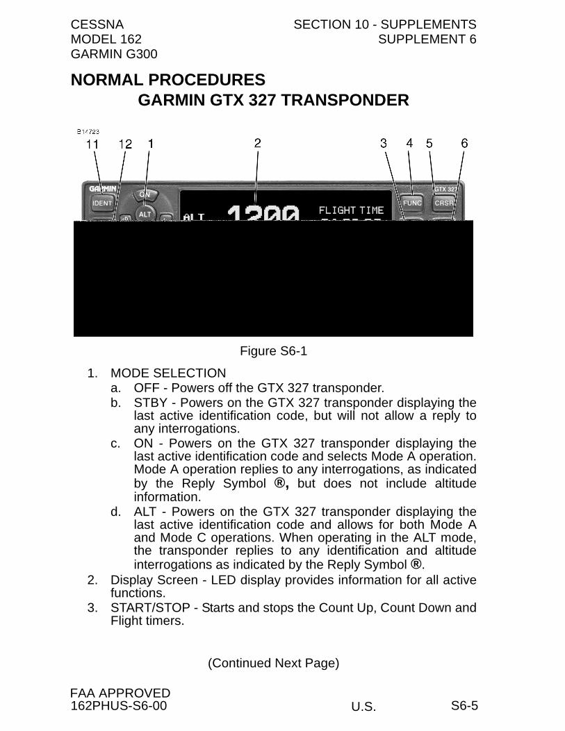
CESSNA SECTION 10 - SUPPLEMENTSMODEL 162 SUPPLEMENT 6GARMIN G300
U.S.FAA APPROVED
NORMAL PROCEDURES
1. MODE SELECTIONa. OFF - Powers off the GTX 327 transponder.b. STBY - Powers on the GTX 327 transponder displaying the
last active identification code, but will not allow a reply toany interrogations.
c. ON - Powers on the GTX 327 transponder displaying thelast active identification code and selects Mode A operation.Mode A operation replies to any interrogations, as indicatedby the Reply Symbol ®, but does not include altitudeinformation.
d. ALT - Powers on the GTX 327 transponder displaying thelast active identification code and allows for both Mode Aand Mode C operations. When operating in the ALT mode,the transponder replies to any identification and altitudeinterrogations as indicated by the Reply Symbol ®.
2. Display Screen - LED display provides information for all activefunctions.
3. START/STOP - Starts and stops the Count Up, Count Down andFlight timers.
(Continued Next Page)
GARMIN GTX 327 TRANSPONDER
Figure S6-1
162PHUS-S6-00 S6-5

SECTION 10 - SUPPLEMENTS CESSNASUPPLEMENT 6 MODEL 162
GARMIN G300
U.S.FAA APPROVED
NORMAL PROCEDURES (Continued)
4. FUNC - Multiple presses of the FUNC key changes the functionpage displayed on the right side of the display screen to one ofthe following pages:a. PRESSURE ALT - Displays pressure altitude in hundreds of
feet.b. FLIGHT TIME - Controlled by the START/STOP key, or can
be configured to START when the airplane exceeds 30 KTSGPS ground speed, and STOP when the airplane slowsbelow 30 KTS.
c. COUNT UP TIMER - Controlled by the START/STOP key.Use CLR key to reset timer to 0:00.
d. COUNT DOWN TIMER - Enter time using numerical keys,and use START/STOP key to activate. Use CLR key to resettimer to 0:00.
5. CRSR - Initiates starting time entry for the Count Down timerand cancels transponder code entry.
6. CLR - Resets the Count Up, Count Down, and Flight timers.Cancels the previous keypress during code selection and CountDown entry. Returns cursor to the fourth code digit within fiveseconds after entry.
7. Numerical keys 8 and 9 are not used for code entry, only forentering the number 8 or 9 into the count down timer.
8. PHOTOCELL - Automatically controls the intensity of the displayfrom low brightness at night to high brightness during daylightoperations. Display brightness may also be controlled manuallyusing the FUNC key.
9. REPLY INDICATOR - The Reply Symbol ® will blink each timethe transponder replies to ground interrogations. The ReplySymbol ® will remain illuminated during the 18 second IDENTtime interval.
10. CODE SELECTION - Code selection is accomplished using thenumerical keys (0 - 7). Pushing one of these keys begins thecode selection sequence. The new code will not be active untilthe fourth digit is entered. Pressing the CLR key will move thecursor back to the previous digit. Pressing the CLR key whenthe cursor is on the first digit, or pressing the CRSR key at anytime will cancel the entry and restore the previous code.
(Continued Next Page)
162PHUS-S6-00S6-6

CESSNA SECTION 10 - SUPPLEMENTSMODEL 162 SUPPLEMENT 6GARMIN G300
U.S.FAA APPROVED
NORMAL PROCEDURES (Continued)
11. IDENT - Pressing the IDENT key activates the Special PositionIdentification (SPI) pulse for 18 seconds, identifying thetransponder return from others on the air traffic controller'sscreen. The word "IDENT" will appear in the upper left corner ofthe display when IDENT mode is active.
12. VFR - Sets the transponder code to 1200 (unless configuredotherwise). Pressing the VFR key again will restore the previousidentification code.
ALTITUDE TREND INDICATOR
When the PRESSURE ALT page is displayed, an arrow may bedisplayed to the right of the altitude, indicating that the altitude isincreasing or decreasing. Two sizes of arrows may be displayeddepending on rate of climb/descent.
AUTOMATIC ALT/STBY MODE SWITCHING
The GTX 327 automatically switches to ALT mode when ground speedexceeds approximately 30 knots GPS ground speed. The unitautomatically returns to STBY mode when the airplane slows below 30knots.
NOTE
The ON (Mode A), ALT (Mode C), and STBY keys can beused at any time to manually override the automatic ALT/STBY mode switching.
PERFORMANCE
There is no change to the airplane performance when the Garmin GTX327 Transponder is installed.
162PHUS-S6-00 S6-7/S6-8

U.S.
CESSNA MODEL 162
Serials 16200001 and On
SUPPLEMENT 7
GARMIN SL 40 VHF COMM TRANSCEIVER
This supplement must be inserted into Section 10 of the Pilot's OperatingHandbook and Airplane Flight Manual when the Garmin SL 40 VHF CommTransceiver is installed.
SERIAL NO.
REGISTRATION NO.
162PHUS-S7-00
COPYRIGHT © 2009CESSNA AIRCRAFT COMPANY
WICHITA, KANSAS, USA
S7-1
2 NOVEMBER 2009
SECTION 10 - SUPPLEMENTS CESSNASUPPLEMENT 7 MODEL 162
GARMIN G300
U.S.FAA APPROVED
SUPPLEMENT 7
GARMIN SL 40 VHF COMM TRANSCEIVER
Use the Log of Effective Pages to determine the current status of thissupplement.
Pages affected by the current revision are indicated by an asterisk (*)preceding the page number.
LOG OF EFFECTIVE PAGES
Supplement Status Date
Original Issue 2 November 2009
PageNumber
PageStatus
RevisionNumber
S7-1 thru S7-8 Original 0
162PHUS-S7-00S7-2
CESSNA SECTION 10 - SUPPLEMENTSMODEL 162 SUPPLEMENT 7GARMIN G300
U.S.FAA APPROVED
SERVICE BULLETIN CONFIGURATION LIST
The following is a list of Service Bulletins that are applicable to theoperation of the airplane, and have been incorporated into thissupplement. This list contains only those Service Bulletins that arecurrently active.
Number Title Airplane Serial Effectivity
Revision Incorporated
Incorporated in Airplane
162PHUS-S7-00 S7-3
SECTION 10 - SUPPLEMENTS CESSNASUPPLEMENT 7 MODEL 162
GARMIN G300
U.S.FAA APPROVED
GARMIN SL 40 VHF COMM TRANSCEIVER
GENERAL
The Garmin SL 40 VHF Comm Transceiver consists of a panel-mounted receiver-transmitter, which includes a 760 channel VHFcommunications receiver-transmitter capable of receiving andtransmitting signals between 118.000 and 136.975 MHz with 25 kHzspacing.
Active and standby frequencies, along with operational annunciators,are displayed on a photocell controlled LCD matrix display. Controlbuttons, including those operating the frequency flip-flop feature,standby frequency monitoring and single-button emergency frequencyselection are located under the display panel. An internal intercom isalso included as a standard feature of the SL40.
Refer to the Garmin SL40 Pilot’s Guide, Garmin P/N 190-00488-00 RevA or later, for a complete listing of system description and operationalinformation.
Garmin publications can be obtained by contact Garmin CustomerService at Garmin International, Inc, (913) 397-8200, Fax (913) 397-8282, 1200 East 151st Street, Olathe, Kansas 66062, USA or visit theGarmin website (www.Garmin.com) for current updates andsupplemental information.
162PHUS-S7-00S7-4

CESSNA SECTION 10 - SUPPLEMENTSMODEL 162 SUPPLEMENT 7GARMIN G300
U.S.FAA APPROVED
OPERATING LIMITATIONS
Headsets are required for all audio communications. Headsets withmicrophones or a hand-held microphone is required for all radiotransmissions.
Transmitting radio communication utilizing the hand-held microphonewill require the operator to depress the push-to-talk button on the hand-held microphone and the push-to-talk (PTT) button on the control stickat the same time while speaking directly into the hand-heldmicrophone.
EMERGENCY PROCEDURES
Pressing the Emergency Channel (EC) button automatically loads theEmergency Channel, 121.500 MHz, as the standby frequency. Themonitor function will be automatically enabled. Pressing the Flip/Flop(<- ->) button will load the emergency channel into the active frequencyfor emergency communications.
In an emergency situation, if the STUCK MIC annunciator messageremains illuminated after you have stopped keying the microphone,turn the power control knob to the off position and then turn back on.Cycling the main power control knob will allow a 35 secondtransmission period prior to experiencing another STUCK MICcondition. Cycling of the SL40 power will be required for all futuretransmission as long as the STUCK MIC annunciator is illuminated.
162PHUS-S7-00 S7-5
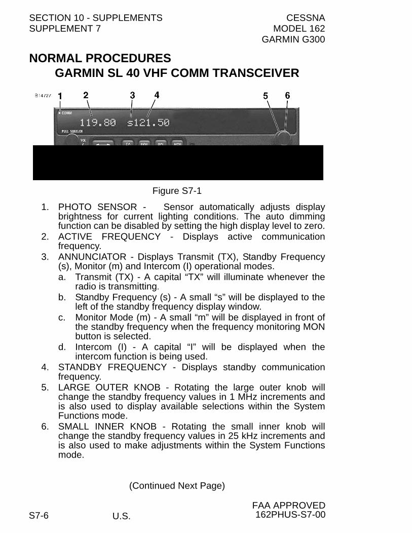
SECTION 10 - SUPPLEMENTS CESSNASUPPLEMENT 7 MODEL 162
GARMIN G300
U.S.FAA APPROVED
NORMAL PROCEDURES
1. PHOTO SENSOR - Sensor automatically adjusts displaybrightness for current lighting conditions. The auto dimmingfunction can be disabled by setting the high display level to zero.
2. ACTIVE FREQUENCY - Displays active communicationfrequency.
3. ANNUNCIATOR - Displays Transmit (TX), Standby Frequency(s), Monitor (m) and Intercom (I) operational modes.a. Transmit (TX) - A capital “TX” will illuminate whenever the
radio is transmitting.b. Standby Frequency (s) - A small “s” will be displayed to the
left of the standby frequency display window. c. Monitor Mode (m) - A small “m” will be displayed in front of
the standby frequency when the frequency monitoring MONbutton is selected.
d. Intercom (I) - A capital “I” will be displayed when theintercom function is being used.
4. STANDBY FREQUENCY - Displays standby communicationfrequency.
5. LARGE OUTER KNOB - Rotating the large outer knob willchange the standby frequency values in 1 MHz increments andis also used to display available selections within the SystemFunctions mode.
6. SMALL INNER KNOB - Rotating the small inner knob willchange the standby frequency values in 25 kHz increments andis also used to make adjustments within the System Functionsmode.
(Continued Next Page)
GARMIN SL 40 VHF COMM TRANSCEIVER
Figure S7-1
162PHUS-S7-00S7-6