16 channel ir/rf remote interface - educypediaeducypedia.karadimov.info/library/ici16.pdf · 16...
TRANSCRIPT
ICI16• 1
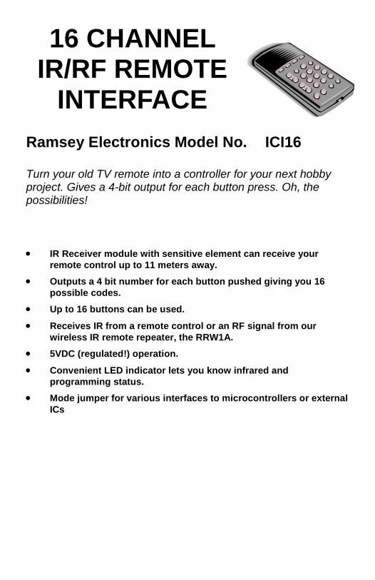
Ramsey Electronics Model No. ICI16
Turn your old TV remote into a controller for your next hobby project. Gives a 4-bit output for each button press. Oh, the possibilities!
• IR Receiver module with sensitive element can receive your remote control up to 11 meters away.
• Outputs a 4 bit number for each button pushed giving you 16 possible codes.
• Up to 16 buttons can be used.
• Receives IR from a remote control or an RF signal from our wireless IR remote repeater, the RRW1A.
• 5VDC (regulated!) operation.
• Convenient LED indicator lets you know infrared and programming status.
• Mode jumper for various interfaces to microcontrollers or external ICs
16 CHANNEL IR/RF REMOTE
INTERFACE

ICI16• 2
RAMSEY TRANSMITTER KITS • FM10A, FM25B FM Stereo Transmitters • FM100B Professional FM Stereo Transmitter • TXE433 or 916 Transmitter & Encoder Module • RXD433 or 916 Data Receiver& Decoder • RR1 Wired remote repeater • RRW1 Wireless remote repeater
RAMSEY RECEIVER KITS
• FR1 FM Broadcast Receiver • AR1 Aircraft Band Receiver • SR2 Short-wave Receiver
RAMSEY HOBBY KITS
• WEB1 Walking Electronic Bug • LEDS1 LED Strobe • BE66 Blinky Eyes • EDF1 Electronic Dripping Faucet • TFM3 Tri-Field Meter • LC1 Inductance-Capacitance Meter
RAMSEY AMATEUR RADIO KITS
• HR Series HF All Mode Receivers • QRP Series HF CW Transmitters • CW7 CW Keyer • DDF1 Doppler Direction Finder • QRP Power Amplifiers
RAMSEY MINI-KITS Many other kits are available for hobby, school, Scouts and just plain FUN. New kits are always under development. Write or call for our free Ramsey catalog.
ICI16 REMOTE INTERFACE KIT MANUAL Ramsey Electronics publication No. ICI16 Revision 1.2
First printing: January 2004 DAR COPYRIGHT 2002 by Ramsey Electronics, Inc. 590 Fishers Station Drive, Victor, New York 14564. All rights reserved. No portion of this publication may be copied or duplicated without the written permission of Ramsey Electronics, Inc. Printed in the United States of America.
ICI16• 3
ICI16 IR/RF CONTROL INTERFACE KIT
Ramsey Publication No. ICI16 Price $5.00
TABLE OF CONTENTS
Introduction ...........................................4 Theory of Operation ..............................5 Learn As You Build ...............................8 Parts List .............................................10 Parts Placement Diagram ...................11 Assembly Steps...................................12 Testing and Programming...................14 Example Hookups ...............................16 Troubleshooting ..................................17 Specifications ......................................19 Schematic Diagram.............................22 Warranty..............................................23
KIT ASSEMBLY AND INSTRUCTION MANUAL FOR
RAMSEY ELECTRONICS, INC. 590 Fishers Station Drive
Victor, New York 14564 Phone (585) 924-4560
Fax (585) 924-4555 www.ramseykits.com

ICI16• 4
ICI16 INTRODUCTION
Welcome to the ICI16 kit . In this manual we will try to help you understand IR remote controls and how they typically work, and also how this kit works, to help you understand what you are building.
Virtually any modern day consumer audio or video device contains an infrared remote control unit. Usually our living room contains several of these to control several different pieces of equipment. In fact we often have so many of these little gems that it becomes necessary to obtain an “all in one” remote control that controls all the functions of your entertainment system. Of course, this leads to having several remote control units delegated to the junk drawer, and that brought about the idea for this kit. Let’s put the old remotes to use controlling an easy to build kit that will control different outputs. By toggling a relay we can live the life of the future by remotely controlling our fans, lamps, and even the coffee pot!
Let’s dig into these units a little bit. A typical infrared remote contains a few functional parts in common with each other; we’ll examine them. First there is some type of keypad assembly. Nowadays this is typically a large molded sheet of rubber with the buttons protruding outward. The end of the button that you cannot see is typically coated with a carbon dot that will make contact with the printed circuit board underneath, completing the circuit when the button is depressed (no, it’s not sad, it is just making contact!). This switch closure will cause an Integrated Circuit on the circuit board to repeat a pre-determined code at the output. This digital signal typically drives an infrared diode to conduct on the front of the unit “broadcasting” the infrared signal to the equipment to be controlled.
Our eyes are sensitive detectors in the visible light range but the wavelength of the infrared diode falls outside that detection range. So we can’t see the diode performing its function. But rest assured, given a fresh battery, it is dutifully doing it over and over again. These codes are unique so that the infrared detector on the equipment can determine what function each of the buttons should be, and perform that operation. These controlling codes are unique to each manufacturer so our kit needs to “learn” these codes to perform the functions we require.
The RF section of the ICI16 is designed to receive pulses from an RF transmitter that simply repeats IR pulses as RF pulses to be picked up. The data is sent in an identical format in RF as it is in IR.
ICI16• 5
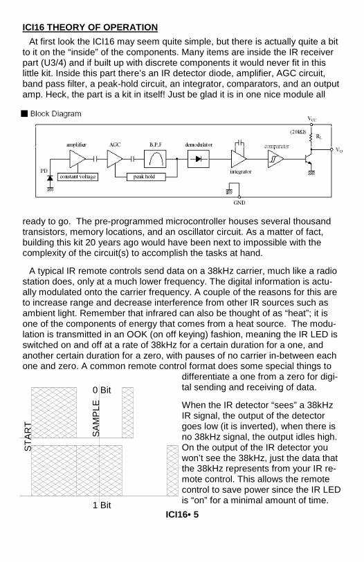
ICI16 THEORY OF OPERATION At first look the ICI16 may seem quite simple, but there is actually quite a bit
to it on the “inside” of the components. Many items are inside the IR receiver part (U3/4) and if built up with discrete components it would never fit in this little kit. Inside this part there’s an IR detector diode, amplifier, AGC circuit, band pass filter, a peak-hold circuit, an integrator, comparators, and an output amp. Heck, the part is a kit in itself! Just be glad it is in one nice module all
ready to go. The pre-programmed microcontroller houses several thousand transistors, memory locations, and an oscillator circuit. As a matter of fact, building this kit 20 years ago would have been next to impossible with the complexity of the circuit(s) to accomplish the tasks at hand.
A typical IR remote controls send data on a 38kHz carrier, much like a radio station does, only at a much lower frequency. The digital information is actu-ally modulated onto the carrier frequency. A couple of the reasons for this are to increase range and decrease interference from other IR sources such as ambient light. Remember that infrared can also be thought of as “heat”; it is one of the components of energy that comes from a heat source. The modu-lation is transmitted in an OOK (on off keying) fashion, meaning the IR LED is switched on and off at a rate of 38kHz for a certain duration for a one, and another certain duration for a zero, with pauses of no carrier in-between each one and zero. A common remote control format does some special things to
differentiate a one from a zero for digi-tal sending and receiving of data.
When the IR detector “sees” a 38kHz IR signal, the output of the detector goes low (it is inverted), when there is no 38kHz signal, the output idles high. On the output of the IR detector you won’t see the 38kHz, just the data that the 38kHz represents from your IR re-mote control. This allows the remote control to save power since the IR LED is “on” for a minimal amount of time.
SAM
PLE
0 Bit
1 Bit
STAR
T

ICI16• 6
Typically a remote control will send data in a format consisting of time slices. To send a zero, the IR LED will be off for one time slice, and then toggled at a rate of 38kHz for the second time slice. To send a one, the IR remote will use three time slices. Off for two time slices, and on for one. This makes things easy on the receiver side, because we just have to look from the edge of the first on-to-off transition to the middle of the second time slice (1 1/2 time slices from the start) to determine the bit that was sent.
It’s important to note, however that most remote controls send a unique first code that can be identified for each and every button as well as each and every remote control. Some remotes will send a full data stream over and over as long as you hold the button down, up to 48 bits per data stream. Other re-motes will only send this full data stream once for the first depression, and then a very short repeat code usually of only one bit, to save on batteries.
The ICI16 recognizes the full codes, and discards the short repeat codes unless you are holding a button in position. If we didn’t do this, we couldn’t tell one button from another! You will find that with some remotes, you need to press the button twice to train the ICI16 to remember a certain button. This means the remote you are using is using repeat codes. Other remotes just require you to press and hold the button, so these are the ones that send the same code over and over.
One other variance is the data rate from the remote. Generally most remotes send at a rate of 2400 Hz time slices, but others send at only 1200 Hz time slices. This presents a problem on slower remotes since the sample period will always lie in a high or low portion of the subsequent data, meaning we will receive nothing but ones or zeros. There is a speed switch you can flip to al-low the ICI16 to work with these remotes. If an incorrect speed remote control is detected, the microcontroller ignores the code. Then you can switch the jumper over to the other speed and try again.
When you train the ICI16, the microcontroller looks at the data stream and rejects those codes it sees as useless or unverified. The ICI16 looks at the data from the remote sensor, makes sure it is not a repeat code, checks that it is not the wrong speed, and then compares it to a previous send before saving the new value in the Flash memory of the controller. That is why you have to press the button twice on some remotes; so you can get the same code for verification before saving.
After the ICI16 locks on to the code it outputs it at J1 as a 4-bit number. The mode switch selects between two different methods of outputting data, and in fact only affects the “VALID” line. With the switch in the up position (1) the valid line will be held low (0V) for the entire depression of the remote control codes being received. The ICI16 could receive the code 200 times in succes-sion, but the line goes low at the end of the first code, and back high after the last code plus a little delay.

ICI16• 7
With the mode switch In the other position (0), the valid line will pulse low for each and every code. 200 valid codes will yield 200 low pulses. Normally the line is held high.
The following shows the progress of receiving five valid codes programmed for code 4 in mode 1 and mode 0.
DATA0
DATA1
DATA2
DATA3
VALID
DATA0
DATA1
DATA2
DATA3
VALID
CO
DE1
CO
DE2
CO
DE3
CO
DE4
CO
DE5
MODE0
MODE1
0
1
0
0
0
1
0
0
0100b = 4
ICI16• 8
RAMSEY “LEARN-AS-YOU-BUILD” ASSEMBLY STRATEGY
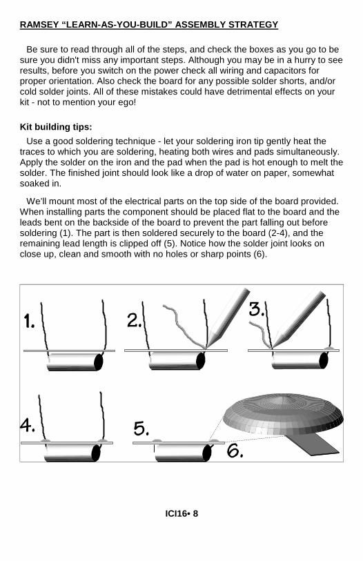
Be sure to read through all of the steps, and check the boxes as you go to be sure you didn't miss any important steps. Although you may be in a hurry to see results, before you switch on the power check all wiring and capacitors for proper orientation. Also check the board for any possible solder shorts, and/or cold solder joints. All of these mistakes could have detrimental effects on your kit - not to mention your ego! Kit building tips:
Use a good soldering technique - let your soldering iron tip gently heat the traces to which you are soldering, heating both wires and pads simultaneously. Apply the solder on the iron and the pad when the pad is hot enough to melt the solder. The finished joint should look like a drop of water on paper, somewhat soaked in.
We’ll mount most of the electrical parts on the top side of the board provided. When installing parts the component should be placed flat to the board and the leads bent on the backside of the board to prevent the part falling out before soldering (1). The part is then soldered securely to the board (2-4), and the remaining lead length is clipped off (5). Notice how the solder joint looks on close up, clean and smooth with no holes or sharp points (6).
ICI16• 9
NOTE TO NEWCOMERS: If you are a first time kit builder we hope you find this manual easier to understand than you may have expected. Each part in the kit is checked off as you go, while a detailed description of each part is given. If you follow each step in the manual in order, and practice good soldering and kit building skills, the kit is next to fail-safe. If a problem does occur the manual will lead you through step by step in the troubleshooting guide until you find the problem and are able to correct it.
Although we know that you are anxious to complete the assembly of your infrared controller kit it is best to follow the step-by-step instructions in this manual. Try to avoid the urge to jump ahead installing components.
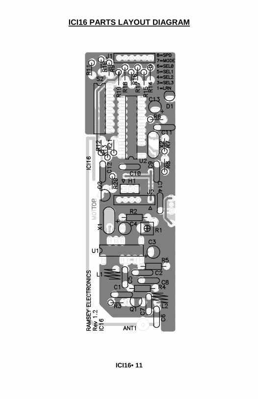
Since you may appreciate some warm-up soldering practice as well as a chance to put some landmarks on the PC board, we’ll first install some of the larger components. This will also help us to get acquainted with the up-down, left-right orientation of the circuit board. Have a look at the parts layout diagram to help with your assembly.
Use the boxes to check off your progress.
Check all received parts against the parts list. The parts list describes the various markings that may be found on the kit parts. Carefully sort the parts into small piles to aid in finding the correct part at the required time.
We will begin by installing the input and output connectors on the rear side of the circuit board. These will act as our landmark components and make the orientation of the rest of the parts a bit easier.
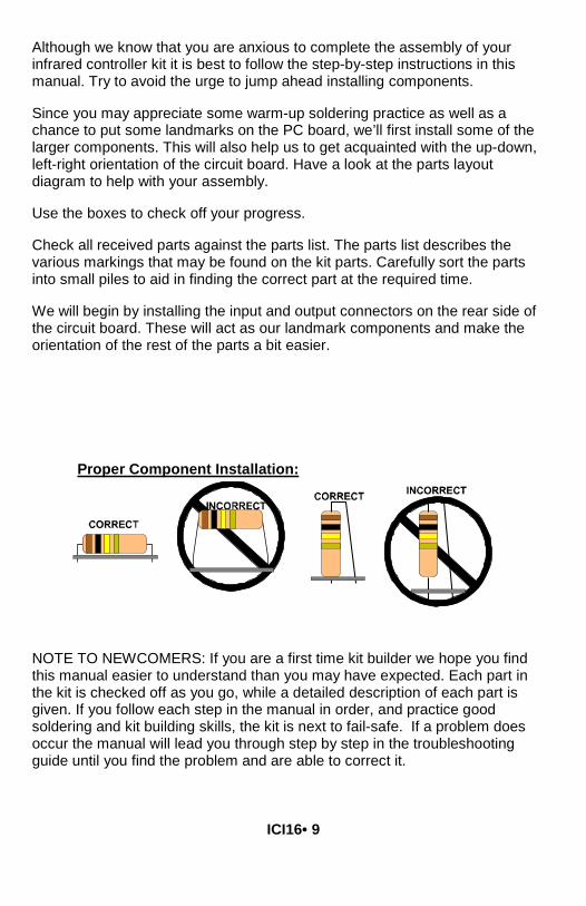
Proper Component Installation:

ICI16• 10
PARTS SUPPLIED WITH YOUR ICI16 KIT Capacitors 1 0.001 uF ceramic disc capacitors [marked 102] (C7) 2 0.01 uF ceramic disc capacitors [marked 103] (C1,C10) 4 0.1 µF ceramic capacitors [marked 104] (C2,C8,C12,C14) 4 10 pF ceramic capacitors [marked 10 or 10K] (C5,C6,C9,C11) 1 1 µF electrolytic capacitor (C4) 2 10 µF electrolytic capacitors (C3, C13)
Resistors 5 100 ohm [brown-black-brown] (R14,R15,R16,R17,R18) 1 220 ohm resistor [red-red-brown] (R6) 1 470 ohm resistor [yellow-violet-brown] (R3) 8 10K ohms [brown-black-orange] (R9,R10,R11,R12,R13.R19,R20,R21) 1 100K ohms [brown-black-yellow] (R4) 2 1M ohm resistor [brown-black-green] (R2,R7) 1 22M ohm resistor [red-red-blue] (R5) 1 100K ohm potentiometer (R1)
Inductors 2 33nH coil Inductors (L1,L2)
Semiconductors and Integrated Circuits 1 MICRF001BN (receiver/data demodulator) (U1) 1 68HC908JK1 Pre-programmed microcontroller (U2) 1 IR Sensor Module (U3) 1 LED (D1) 1 2SC2570 transistor (Q1) 1 BS170 N-Channel MOSFET (Q2)
Miscellaneous Components 1 20 pin IC socket for microcontroller U1 1 16 pin DIP switch (S2) 1 3-pin header (H1) 1 Jumper header 1 6 pin header (J1, J2) 1 9.8304 MHz crystal (Marked 9.8304) (X2) 1 3.3149MHz crystal (Marked 3.3149) (X1)
ICI16• 11
ICI16 PARTS LAYOUT DIAGRAM
ICI16• 12
ICI16 PC BOARD ASSEMBLY STEPS
1. A few of the parts will be soldered on the bottom of the board, the side with the traces and without a silkscreen. We’ll start with two of these parts first. Locate one of the 6 pin headers and install it into the J1 position. The short side of the header pins will be pushed up through the bottom of the PC board and the long part of the pins will be sticking out underneath the board. Solder all 6 pins solidly.
2. In the same way, install J2 on the bottom of the PC board and solder all six pins.
3. Orienting the PC board as it is shown on the previous page, let’s start at the bottom of the board. Install C6, 10 pF ceramic disc capacitor [marked 10].
4. Install C7, 0.001 uF ceramic disk capacitor [marked 102], next to C6.
5. Install Q1, 2SC2570 transistor [marked 2570]. Make sure it goes in the right way. The flat side should line up with the flat side marked on the board drawing and PC board silkscreen.
6. Install R3, 470 ohm resistor [yellow-violet-brown], to the left of Q1. Install it vertical style.
7. Install C1, 0.01 uF ceramic disc capacitor [marked 103], above C1.
8. Install R4, 100K ohm resistor [brown-black-yellow], up and to the right of C1.
9. Install L2, 33 nH inductor [air coil], to the right of R4.
10. Install C8, 0.1 uF ceramic disc capacitor [marked 104], above R4.
11. Install C2, 0.1 uF ceramic disc capacitor [marked 104], above C8.
12. Install R5, 22M ohm resistor [red-red-green], above C2.
13. Install C5, 10 pF ceramic disc capacitor [marked 10], to the left of C2.
14. Install L1, 33 nH inductor [air coil], to the left of C5.
15. Install C3, 10 uF electrolytic capacitor, above R5. Watch that polarity. There should be a “-” band on the cap and a “+” spot on the board. Don’t put the “+” lead in the “-” hole.
16. Install U1, MICRF001BN receiver/data demodulator [marked MICRF001BN], to the left of C3. Line up the notch with the notch on the board drawing. This chip chews up RF and spews out yummy data. It comes into play when you use the ICI16 with our wireless IR remote repeater.
ICI16• 13
17. Install R1, 100K ohm potentiometer [little orange top thingy marked 104], above C3.
18. Install C4, 1 µF electrolytic capacitor. Remember to orient the part by the negative stripe and the ‘+’ sign on the board silkscreen.
19. Install R2, 1M ohm resistor [brown-black-green], above R1.
20. Install X1, 3.3149MHz crystal [metal can], to the left of C4.
21. Install C14, 0.1 uF ceramic disc capacitor [marked 104].
You’ll notice a silkscreened position for a resistor, R8. R8 is not needed; do not install any part in this position.
22. Install H1, 3 pin header above J2.
23. Install Q2, BS170 power transistor, to the left of J2. Line up the flat spot with the flat spot on the board drawing.
24. Install R20, 10K ohm resistor [brown-black-orange], above and to the right of Q2. Install it vertically.
25. Install C12, 0.1 uF ceramic disc capacitor [marked 104], to the left of R20.
26. Install C10, 0.01 uF ceramic disc capacitor [marked 103], above H1.
27. Install R12, 10K ohm resistor [brown-black-orange], above C12.
28. Install R13, 10K ohm resistor [brown-black-orange], next to R12.
29. Install R21, 10K ohm resistor [brown-black-orange]. Next to R13.
30. Install the IC socket for U2, above C10. Then, insert the 68HC908JK1 microcontroller. Line up the notch on the chip with the notch on the board drawing. Be sure all the IC pins are in the socket and not bent under or out.
31. Install X2, 9.8304 MHz crystal [marked 98304], to the right of U2.
32. Install C9, 10 pF ceramic disc capacitor [marked 10], below X2.
33. Install R7, 1M ohm resistor [brown-black-orange], next to X2. Install it vertically.
34. Install C11, 10 pF ceramic disc capacitor [marked 10], above R7.
35. Install R6, 220 ohm resistor [red-red-brown], above C11.
36. Install C13, 10 uF electrolytic capacitor, above R6. Watch polarity.
37. Install D1, LED, to the right of C13. You’ll note that the part has a flat side on it and the silkscreen shows a flat side too. Orient both flat sides and leave the LED up off the PC board as far as you need to so that you can see it later when you’re programming.

ICI16• 14
38. Install R14, 100 ohm resistor [brown-black-brown], above C13. Install vertically.
39. Install R15, 100 ohm resistor [brown-black-brown], to the left of R14. Install vertically.
40. Install R17, 100 ohm resistor [brown-black-brown], to the left of R15. Install vertically.
41. Install R16, 100 ohm resistor [brown-black-brown], to the left of R17. Install vertically.
42. Install R18, 100 ohm resistor [brown-black-brown], to the left of R17. Install vertically.
43. Install R19, 10 K ohm resistor [brown-black-orange], to the left of R18. Install vertically.
44. Install R9, 10 K ohm resistor [brown-black-orange], to the left of R19. Install vertically.
45. Install R10, 10 K ohm resistor [brown-black-orange], to the left of R9.
46. Install R11, 10 K ohm resistor [brown-black-orange], to the left of R10.
47. Install S2, dip switch block. The switches should face the outside of the PC board to make it easier to flip them later.
48. We have one last part to install and it’s going on the back side of the board with the first connectors we installed. It is the IR sensor module, U3. It goes into the three holes next to C14. Check its position on the topside of the board, then install it on the bottom. Leave the leads standing up off the board a bit to make it easier for your remote to “see” the sensor and solder it so that it’s facing the outside edge of the PC board. Solder all three leads.
CONGRATULATIONS ! Your Remote Control Interface kit is now complete! Have a final look over your work, paying particular attention to the orientation of diodes, capacitors, and IC’s. Remember that any problems you find now can save time and effort after the unit has been cased up and final assembled. TESTING AND PROGRAMMING YOUR ICI16
To begin testing the ICI16 we will need the following items:
Regulated 5VDC power.
An infrared remote control

ICI16• 15
Apply 5V DC to pins 1 and 2 on header J2. Pin 1 is denoted with a triangle symbol. Install included header jumper between pins 2 and 3 to select IR mode. You are now ready to program your ICI16.
PROGRAMMING YOUR ICI16
Remember to install some fresh batteries in your remote control, and aim the infrared LED towards the photo sensor. Set switch 8 on S2 down, set the others up. Switch 1 is the switch nearest to R1 on the PC board. Switch 8 is at the other end. Depress any button you want to use on your remote control. The LED should begin to blink as the unit receives the infrared code from the transmitter. This testing verifies the operation of the detector and associated circuitry. It will also provide some clues to the operation of the remote control unit (remember we talked about this in the theory of operation) as you may see a long “burst” of code followed by successive shorter pulse trains, or you may see the pulse train being repeated over and over. If you have access to an oscilloscope you can even observe this pulse train on the detector “output “pin, which is tied to pins 1 and 19 of the microcontroller.
Now we will set our controller to the “learn” mode to memorize the pulse trains from our remote, and configure the switch S2 to learn 16 codes as we move along. The controller is placed into learning mode by setting the first switch in the S2 switch block to “1” (down). Now the unit is waiting to memorize the code for your remote. Depress the button on your remote control unit and the LED on the front panel will blink. Just to be safe, push the button on your remote control unit twice to ensure that the micro has memorized your remote control’s pulse train. You may continue to program up to 15 more buttons.
0000 0 1000 8
0001 1 1001 9
0010 2 1010 10
0011 3 1011 11
0100 4 1100 12
0101 5 1101 13
0110 6 1110 14
0111 7 1111 15
S3,4,5,6 Code # S3,4,5,6 Code #
1 = Up, 0 = Down S1 = Learn (0 = Learn Mode, 1 = Idle) S7 = Mode (0 = Pulsed, 1 = Continuous) S8 = Speed (0 = 1200, 1 = 2400)
ICI16• 16
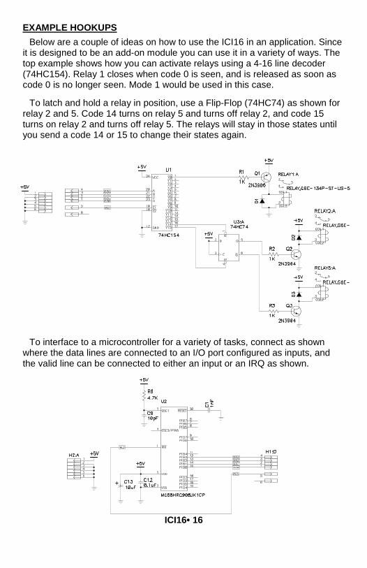
EXAMPLE HOOKUPS Below are a couple of ideas on how to use the ICI16 in an application. Since
it is designed to be an add-on module you can use it in a variety of ways. The top example shows how you can activate relays using a 4-16 line decoder (74HC154). Relay 1 closes when code 0 is seen, and is released as soon as code 0 is no longer seen. Mode 1 would be used in this case.
To latch and hold a relay in position, use a Flip-Flop (74HC74) as shown for relay 2 and 5. Code 14 turns on relay 5 and turns off relay 2, and code 15 turns on relay 2 and turns off relay 5. The relays will stay in those states until you send a code 14 or 15 to change their states again.
To interface to a microcontroller for a variety of tasks, connect as shown where the data lines are connected to an I/O port configured as inputs, and the valid line can be connected to either an input or an IRQ as shown.

ICI16• 17
TROUBLESHOOTING GUIDE If your ICI16 does not work at all, re-check the following:
• correct orientation of ICs, Q1, Q2, and the electrolytic capacitors (see PC board layout diagram).
• all solder connections PROBLEM: The green LED doesn’t blink when I aim my remote at it. SOLUTION: There are a few things that can go wrong here, so we will go from the most likely to the least.
1. The power to the module is not connected correctly.
2. You installed the green LED in backwards. Please check the orientation.
3. Your remote control’s battery is shot. Replace the battery.
4. The speed is set in the wrong position (switch S8, see chart on page 15).
5. The jumper on H1 is set to RF rather than IR. Try swapping positions.
6. It is an ancient remote that has a hammer and chimes inside. Those just won’t work; this is for IR remotes or our RRW1A remote RF repeater.
7. You are trying to yse an IR remote that is modulated at some other fre-quency than 38kHz. There are some other ranges available but 38kHz is by far the most common. Most consumer components operate at 38kHz. This product ONLY works at 38kHz.
PROBLEM: The LED stays constantly lit. SOLUTION: The IR detector too near to the IR LED/ or a noise source is satu-rating the detector. The IR detector can become saturated and remain on, jamming the unit. Also is possible there is a lot of RF interference at 433MHz, where the RF section operates. Try moving the unit to another location.
ICI16• 18
STILL HAVING TROUBLE? While we had hoped that it wouldn’t come to this, if you are still having trouble with your IR Remote Control Interface, here are a few additional suggestions. Use a methodical, logical troubleshooting technique. Most problems can be solved using common sense. A volt-ohm meter and a clear head are usually all that are needed to correct any problem. Most problems are due to misplaced parts and/or bad solder connections. Working backwards through the assembly steps will often lead you to the problem. Re-visit the extensive theory of operation include in this manual, and try to apply to your specific problem. Have another set of eyes look through your work. Here at the shop we have often run into a “stone wall” of a problem only to have a fellow technician see our obvious error. It is sometimes very difficult to see your own mistake, taking a break can often solve this common problem. Make sure that you have “checked” all the assembly steps boxes, you may have forgotten one or two of them. PROBLEM: I just can’t make the &#^$^@! thing work! SOLUTION: Call Ramsey Support at 1-585-924-4560 or look at the warranty in this manual. We are here to help, and reduce your frustration as much as possible. It usually is something simple. Have your board revision handy to help our technicians find the proper schematic for your needs. You can email our tech support as well at the ramseykits.com website. Oh, please count to ten before calling taking some deep breaths first...

ICI16• 19
ICI16 INFRARED CONTROLLER INTERFACE SPECIFICATIONS Here are few of the commonly requested specifications for the ICI16: J5 Power Input - Input working voltage range: 5VDC regulated only. - Max ICI16 current draw is between 20-50mA. Miscellaneous Information - PCB Dimensions: 4.45”x1.455” - Hole centers 0.100” on headers.
CONCLUSION We sincerely hope that you enjoy the use of this Ramsey product. As always, we have tried to compose our manual in the easiest, most user-friendly format that is possible. As our customers, we value your opinions, comments, and additions that you would like to see in future publications. Please submit comments or ideas to: Ramsey Electronics Inc. Attn. Hobby Kit Department 590 Fishers Station Drive Victor, NY 14564 Please also feel free to visit our Website at www.ramseykits.com and offer your observations to other kit enthusiasts as well. And once again, thanks from the folks here at Ramsey!

ICI16• 20
These pages were intentionally left blank to provide plenty of room for notes!

ICI16• 21

ICI16• 22

ICI16• 23
The Ramsey Kit Warranty Please read carefully BEFORE calling or writing in about your kit. Most problems can be solved without contacting the factory. Notice that this is not a "fine print" warranty. We want you to understand your rights and ours too! All Ramsey kits will work if assembled properly. The very fact that your kit includes this new manual is your assurance that a team of knowledgeable people have field-tested several "copies" of this kit straight from the Ramsey Inventory. If you need help, please read through your manual carefully. All information required to properly build and test your kit is contained within the pages!
1. DEFECTIVE PARTS: It's always easy to blame a part for a problem in your kit, Before you conclude that a part may be bad, thoroughly check your work. Today's semiconductors and passive components have reached incredibly high reliability levels, and it’s sad to say that our human construction skills have not! But on rare occasions a sour component can slip through. All our kit parts carry the Ramsey Electronics Warranty that they are free from defects for a full ninety (90) days from the date of purchase. Defective parts will be replaced promptly at our expense. If you suspect any part to be defective, please mail it to our factory for testing and replacement. Please send only the defective part(s), not the entire kit. The part(s) MUST be returned to us in suitable condition for testing. Please be aware that testing can usually determine if the part was truly defective or damaged by assembly or usage. Don't be afraid of telling us that you 'blew-it', we're all human and in most cases, replacement parts are very reasonably priced.
2. MISSING PARTS: Before assuming a part value is incorrect, check the parts listing carefully to see if it is a critical value such as a specific coil or IC, or whether a RANGE of values is suitable (such as "100 to 500 uF"). Often times, common sense will solve a mysterious missing part problem. If you're missing five 10K ohm resistors and received five extra 1K resistors, you can pretty much be assured that the '1K ohm' resistors are actually the 'missing' 10 K parts ("Hum-m-m, I guess the 'red' band really does look orange!") Ramsey Electronics project kits are packed with pride in the USA. If you believe we packed an incorrect part or omitted a part clearly indicated in your assembly manual as supplied with the basic kit by Ramsey, please write or call us with information on the part you need and proof of kit purchase.
3. FACTORY REPAIR OF ASSEMBLED KITS:
To qualify for Ramsey Electronics factory repair, kits MUST:
1. NOT be assembled with acid core solder or flux.
2. NOT be modified in any manner.
3. BE returned in fully-assembled form, not partially assembled.
4. BE accompanied by the proper repair fee. No repair will be undertaken until we have received the MINIMUM repair fee (1/2 hour labor) of $25.00, or authorization to charge it to your credit card account.
5. INCLUDE a description of the problem and legible return address. DO NOT send a separate letter; include all correspondence with the unit. Please do not include your own hardware such as non-Ramsey cabinets, knobs, cables, external battery packs and the like. Ramsey Electronics, Inc., reserves the right to refuse repair on ANY item in which we find excessive problems or damage due to construction methods. To assist customers in such situations, Ramsey Electronics, Inc., reserves the right to solve their needs on a case-by-case basis.
The repair is $50.00 per hour, regardless of the cost of the kit. Please understand that our technicians are not volunteers and that set-up, testing, diagnosis, repair and repacking and paperwork can take nearly an hour of paid employee time on even a simple kit. Of course, if we find that a part was defective in manufacture, there will be no charge to repair your kit (But please realize that our technicians know the difference between a defective part and parts burned out or damaged through improper use or assembly).
4. REFUNDS: You are given ten (10) days to examine our products. If you are not satisfied, you may return your unassembled kit with all the parts and instructions and proof of purchase to the factory for a full refund. The return package should be packed securely. Insurance is recommended. Please do not cause needless delays, read all information carefully.

ICI16• 24
ICI16 REMOTE INTERFACE KIT Quick Reference Page Guide
Introduction ...........................................4 Theory of Operation ..............................5 Learn As You Build................................8 Parts List .............................................10 Parts Placement Diagram ...................11 Specifications ......................................21 Schematic Diagram.............................22 Warranty..............................................23
Price: $5.00 Ramsey Publication No. MICI1 Assembly and Instruction manual for: RAMSEY MODEL NO. ICI16
REQUIRED TOOLS • Soldering Iron Ramsey #RTS06 • Thin Rosin Core Solder Ramsey #RTS12 • Needle Nose Pliers Ramsey #RTS05 • Small Diagonal Cutters Ramsey #RTS04 ADDITIONAL SUGGESTED ITEMS • Soldering Iron Holder/Cleaner (RS64-2078) • Holder for PC Board/Parts Ramsey #RTS13, • Desoldering Braid Ramsey #RTS08
ESTIMATED ASSEMBLY
TIME Beginner ...............2 hrs Intermediate .........1.25 hrs Advanced .............0.75 hrs
RAMSEY ELECTRONICS, INC. 590 Fishers Station Drive Victor, New York 14564 Phone (585) 924-4560 Fax (585) 924-4555 www.ramseykits.com