16 channel color triplex multiplexer - jscctv.com16 channel color triplex multiplexer, a real time...
TRANSCRIPT
1
16 Channel Color
Triplex Multiplexer
User’s Manual
and
Operation Instructions
Version 1.0

2
Table of Content Safety Warning 1 Introduction 2 Specification 3 Systems connection 4 Front Panel definition 4 Rear Panel definition 5 Mode function description 6 1. Overview 6 2. Full Screen display 7 3. Quad Screen display 7 4. 9-CH screen display 7 5. 13-CH and 16-CH screen display 8 6. Auto Sequential Switching 9 7. Zoom display function 9 8. Freeze display function 9 9. Call Monitor 9 Pin Assignment 10 1. Alarm port 10 2. RS-485 port 10 3. S-VHS port 10 4. Loop switch 10 Functional Setting 11 Menu setup 11 Language Select 11 Date, Time & OSD setup 11 1. Date &Time setting 11 2. Save Setting 11 Camera Setup 12 1. Select Channel 12 2. Brightness 12 3. Sharpness 12 4. Vloss Indicator 12 5. Title of Camera 12 Alarm Setup 13 1. Alarm Function 13 2. Alarm Duration 13 3. Alarm Buzzer 13

3
4. Alarm Indicator 13 Alarm channel 13 1. Select Channel 13 2. Alarm Polarity 14 3. POP-OUT Monitor 14 Record Setup 14 1. VCR recording time setting 14 2. VCR trigger setting 14 3. VCR input type setting 14 Select Channel 15
1. Select Channel 15 2. Normal Record 15 3. Alarm Weighted 15 4. Motion Weighted 15 Event Setup 16 1. Alarm Event Log 16 2. Loss Camera Log 16 3. Blind Camera Log 16 4. Motion Event Log 16 5. Clear History 16 6. History Listing 16 Motion Setup 17 1. Motion Function 17 2. Motion Buzzer 17 3. Motion Duration 17 4. Motion Indicator 17 Motion Channel 18 1. Select Channel 18 2. Motion Active 18 3. Window visible 18 4. Sensitivity 19 5. Motion Velocity 19 6. Motion Area 19 There are 5 colors represent the state 19 1. Purple color 19 2. Green color 19 3. Transparent 19 4. Cursor in red color 19
4
5. Cursor in blue color 19 Remote setup 20 1. Machine Address ID 20
2. Machine Name 20 3. Port 1 Device Type 20
4. Port 2 Device Type 20 5. Port Cross Link 20 System Setup 21 1. Sequence Dwell Time Setting 21 2. Video Type Setting 21 3. Next Size 21 4. Timer Display 21 5. Title Display 22 6. On-Screen Indicator 22 7. Horizon Shift 22 8. Vertical Shift 22 9. Key-Lock Level 22 10. Password 22 11. System Default Setting 22
5
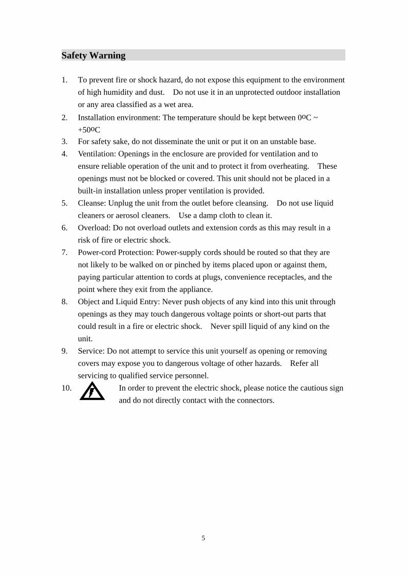
Safety Warning 1. To prevent fire or shock hazard, do not expose this equipment to the environment
of high humidity and dust. Do not use it in an unprotected outdoor installation or any area classified as a wet area.
2. Installation environment: The temperature should be kept between 0oC ~ +50oC 3. For safety sake, do not disseminate the unit or put it on an unstable base. 4. Ventilation: Openings in the enclosure are provided for ventilation and to ensure reliable operation of the unit and to protect it from overheating. These openings must not be blocked or covered. This unit should not be placed in a built-in installation unless proper ventilation is provided. 5. Cleanse: Unplug the unit from the outlet before cleansing. Do not use liquid cleaners or aerosol cleaners. Use a damp cloth to clean it. 6. Overload: Do not overload outlets and extension cords as this may result in a risk of fire or electric shock. 7. Power-cord Protection: Power-supply cords should be routed so that they are not likely to be walked on or pinched by items placed upon or against them,
paying particular attention to cords at plugs, convenience receptacles, and the point where they exit from the appliance. 8. Object and Liquid Entry: Never push objects of any kind into this unit through openings as they may touch dangerous voltage points or short-out parts that could result in a fire or electric shock. Never spill liquid of any kind on the unit. 9. Service: Do not attempt to service this unit yourself as opening or removing covers may expose you to dangerous voltage of other hazards. Refer all servicing to qualified service personnel. 10. In order to prevent the electric shock, please notice the cautious sign
and do not directly contact with the connectors.
6
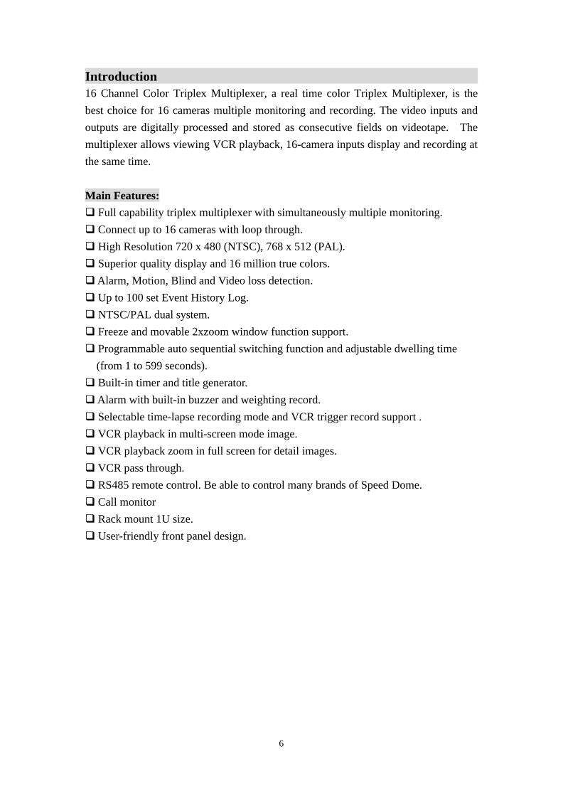
Introduction 16 Channel Color Triplex Multiplexer, a real time color Triplex Multiplexer, is the best choice for 16 cameras multiple monitoring and recording. The video inputs and outputs are digitally processed and stored as consecutive fields on videotape. The multiplexer allows viewing VCR playback, 16-camera inputs display and recording at the same time.
Main Features: q Full capability triplex multiplexer with simultaneously multiple monitoring. q Connect up to 16 cameras with loop through. q High Resolution 720 x 480 (NTSC), 768 x 512 (PAL). q Superior quality display and 16 million true colors. q Alarm, Motion, Blind and Video loss detection. q Up to 100 set Event History Log. q NTSC/PAL dual system. q Freeze and movable 2xzoom window function support. q Programmable auto sequential switching function and adjustable dwelling time
(from 1 to 599 seconds). q Built-in timer and title generator. q Alarm with built-in buzzer and weighting record. q Selectable time-lapse recording mode and VCR trigger record support . q VCR playback in multi-screen mode image. q VCR playback zoom in full screen for detail images. q VCR pass through. q RS485 remote control. Be able to control many brands of Speed Dome. q Call monitor q Rack mount 1U size. q User-friendly front panel design.

7
Specification System format: NTSC / PAL programmable Video input: 16 cameras inputs, 1V p-p/75 ohm,
1 VCR input, 1V p-p/75 ohm Video output: 16 video with loop through outputs, 1V p-p/75 ohm Monitor output: BNC&Y/C video outputs (1V p-p/75 ohm) Recording output: BNC&Y/C video output, 1V p-p/75 ohm Refresh rate: 60 fields/sec. (NTSC), 50 fields/sec. (PAL) Resolution: 720 x 480 (NTSC), 768 x 512 (PAL) VCR playback: Yes Playback zoom: Yes Video freeze: Yes Video loss detection: Yes
Record: Selectable time-lapse recording mode or VCR trigger.
Alarm input: 16 alarm inputs Alarm output: 1 Normally Open, 1 Normally Closed relay output Buzzer: Yes Title: 8 characters title generator for each camera input Timer: Built-in real time clock Setup: On screen setup Switching: Programmable auto sequential switch and adjustable
dwelling time (1-599 sec.) Remote control: 2 RS485 port Power source: Power Adaptor DC 5V / 5 A Power consumption: 20W max. Dimension: 430x 343x 44 mm Weight: 3.4 Kg.
8
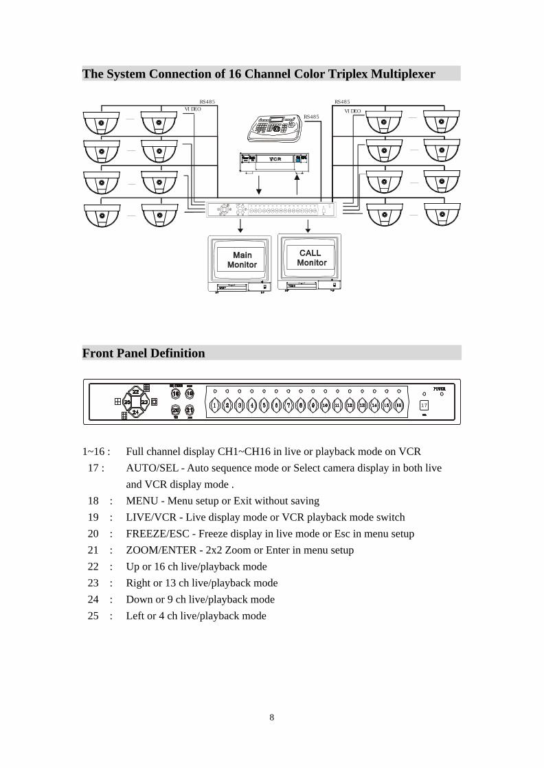
The System Connection of 16 Channel Color Triplex Multiplexer
RS485
RS485VIDEO
RS485VIDEO
Front Panel Definition
17
1~16 : Full channel display CH1~CH16 in live or playback mode on VCR 17 : AUTO/SEL - Auto sequence mode or Select camera display in both live and VCR display mode . 18 : MENU - Menu setup or Exit without saving 19 : LIVE/VCR - Live display mode or VCR playback mode switch 20 : FREEZE/ESC - Freeze display in live mode or Esc in menu setup 21 : ZOOM/ENTER - 2x2 Zoom or Enter in menu setup 22 : Up or 16 ch live/playback mode 23 : Right or 13 ch live/playback mode 24 : Down or 9 ch live/playback mode 25 : Left or 4 ch live/playback mode
9
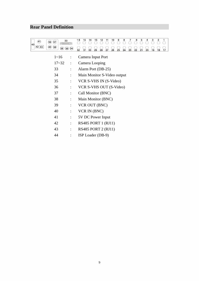
Rear Panel Definition
1~16 : Camera Input Port 17~32 : Camera Looping 33 : Alarm Port (DB-25) 34 : Main Monitor S-Video output 35 : VCR S-VHS IN (S-Video) 36 : VCR S-VHS OUT (S-Video) 37 : Call Monitor (BNC) 38 : Main Monitor (BNC) 39 : VCR OUT (BNC) 40 : VCR IN (BNC) 41 : 5V DC Power Input 42 : RS485 PORT 1 (RJ11) 43 : RS485 PORT 2 (RJ11) 44 : ISP Loader (DB-9)
10
Mode Function Description Overview : In the 16-ch multiplex , the display mode is divided into two main display mode : Live display mode and VCR playback mode . Both Live display mode and VCR playback mode are divided into Full screen display , Quad screen display , 9-CH screen display , 13-CH screen display and 16-CH screen display . Note : 1. If you change the mode from VCR playback mode into Live display mode,
the image of CH1 window will take a little time to be present . 2. If you change the mode from Live display mode into VCR playback mode,
the image of playback video will take a little time to be displayed in all channel path .
3. During VCR playback mode, the output of the VCR out port is no camera #1 video signal. If turn back to live display mode, the camera #1 video signal will be present in the VCR out port.
4. After you select any kind of camera index in all split mode, this camera index table will be remembered even if you have this split mode. After you back to this split mode, the camera index is the same as former camera index table you had selected.
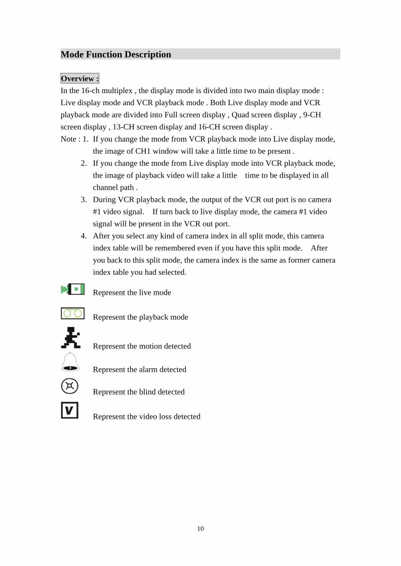
Represent the live mode
Represent the playback mode
Represent the motion detected
Represent the alarm detected
Represent the blind detected
Represent the video loss detected
11
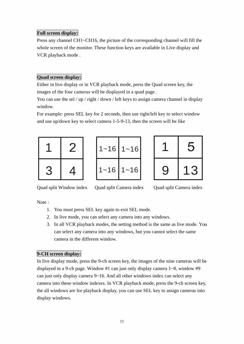
Full screen display: Press any channel CH1~CH16, the picture of the corresponding channel will fill the whole screen of the monitor. These function keys are available in Live display and VCR playback mode . Quad screen display: Either in live display or in VCR playback mode, press the Quad screen key, the images of the four cameras will be displayed in a quad page . You can use the sel / up / right / down / left keys to assign camera channel in display window. For example: press SEL key for 2 seconds, then use right/left key to select window and use up/down key to select camera 1-5-9-13, then the screen will be like
1
3 4
1~16 1~16
1~16 1~16
1
9 13
Quad split Window index Quad split Camera index Quad split Camera index Note :
1. You must press SEL key again to exit SEL mode. 2. In live mode, you can select any camera into any windows. 3. In all VCR playback modes, the setting method is the same as live mode. You
can select any camera into any windows, but you cannot select the same camera in the different window.
9-CH screen display: In live display mode, press the 9-ch screen key, the images of the nine cameras will be displayed in a 9-ch page. Window #1 can just only display camera 1~8, window #9 can just only display camera 9~16. And all other windows index can select any camera into these window indexes. In VCR playback mode, press the 9-ch screen key, the all windows are for playback display, you can use SEL key to assign cameras into display windows.

12
1 2 34 5 67 8 9
9 split window index 9 split camera index
13-CH screen display: In live display mode, press the13-ch screen key, the images of the 13 cameras will be displayed in a 13-ch page. In VCR playback mode, press the 13-ch screen key, the main window will be a playback channel and the others will be live display channel. In live mode, you can use SEL key to assign cameras into display windows. Window #2,#3,#4,#6 and #7 can just only display camera 1~8, window #9, #10, #11, #12, and #13 can just only display camera 9~16. Window #1 and #5 can display camera 1~16. In VCR display mode, you can just only use SEL key to assign any cameras into the main window.
13 split window index 13 split window index
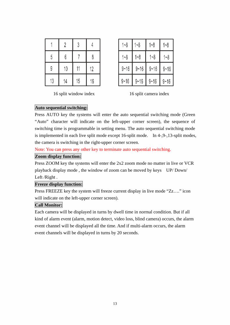
16-CH screen display: In live display mode, press the 16-ch screen key, the images of the nine cameras will be displayed in a 16-ch page . Camera 1-8 can just only be assigned into window 1, 2, 3, 4, 5, 6, 7 or 8. Camera 9-16 can just only be assigned into windows 9, 10, 11, 12, 13, 14, 15 or 16. In VCR playback mode, press the 16-ch screen key, the all windows are for playback display. In live mode, you can use SEL key to assign cameras into display windows. But in VCR display mode you cannot use SEL key to assign cameras into any window.
13
16 split window index 16 split camera index
Auto sequential switching: Press AUTO key the systems will enter the auto sequential switching mode (Green “Auto” character will indicate on the left-upper corner screen), the sequence of switching time is programmable in setting menu. The auto sequential switching mode is implemented in each live split mode except 16-split mode. In 4-,9-,13-split modes, the camera is switching in the right-upper corner screen. Note: You can press any other key to terminate auto sequential switching.
Zoom display function: Press ZOOM key the systems will enter the 2x2 zoom mode no matter in live or VCR playback display mode , the window of zoom can be moved by keys UP/ Down/ Left /Right . Freeze display function: Press FREEZE key the system will freeze current display in live mode “Zz… .” icon will indicate on the left-upper corner screen). Call Monitor: Each camera will be displayed in turns by dwell time in normal condition. But if all kind of alarm event (alarm, motion detect, video loss, blind camera) occurs, the alarm event channel will be displayed all the time. And if multi-alarm occurs, the alarm event channels will be displayed in turns by 20 seconds.

14
Pin Assignment
ALARM PORT (DB-25 Female) 1~16 : Alarm Input CH1~CH16
17 : VCR Trigger 18~20 : GND
21 : Alarm Output NC 22 : Alarm Output COM 23 : Alarm Output NO
RS-485 PORT 1/2 (RJ-11) 1 : Reserved 2 : Reserved 3 : Data + 4 : Data -
5 : Reserved 6 : Reserved S-VHS PORT
1 : GND 2 : GND 3 : Y 4 : C LOOP switch
32
4
1
13 12 11 10 9 8 7 6 5 4 3 2 1
25 24 23 22 21 20 19 18 17 16 15 14
654321
15
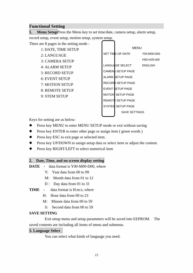
Functional Setting 1. Menu SetupPress the Menu key to set time/date, camera setup, alarm setup, record setup, event setup, motion setup, system setup. There are 8 pages in the setting mode : 1: DATE, TIME SETUP 2: LANGUAGE
3: CAMERA SETUP 4: ALARM SETUP 5: RECORD SETUP 6: EVENT SETUP
7: MOTION SETUP 8: REMOTE SETUP
9: STEM SETUP Keys for setting are as below: l Press key MENU to enter MENU SETUP mode or exit without saving l Press key ENTER to enter other page or assign item ( green words ) l Press key ESC to exit page or selected item. l Press key UP/DOWN to assign setup data or select item or adjust the content. l Press key RIGHT/LEFT to select numerical item
2. Date, Time, and on screen display setting DATE - data format is Y00-M00-D00, where Y: Year data from 00 to 99 M: Month data from 01 to 12
D : Day data from 01 to 31 TIME - data format is H:m:s, where H: Hour data from 00 to 23 M : Minute data from 00 to 59 S: Second data from 00 to 59 SAVE SETTING Exit setup menu and setup parameters will be saved into EEPROM. The saved contents are including all items of menu and submenu. 3. Language Select You can select what kinds of language you need.
MENU
SET TIME-OF-DATE Y00:M00:D00
H00:m00:s00
LANGUAGE SELECT ENGLISH
CAMERA SETUP PAGE
ALARM SETUP PAGE
RECORD SETUP PAGE
EVENT SETUP PAGE
MOTION SETUP PAGE
REMOTE SETUP PAGE
SYSTEM SETUP PAGE
SAVE SETTINGS
16
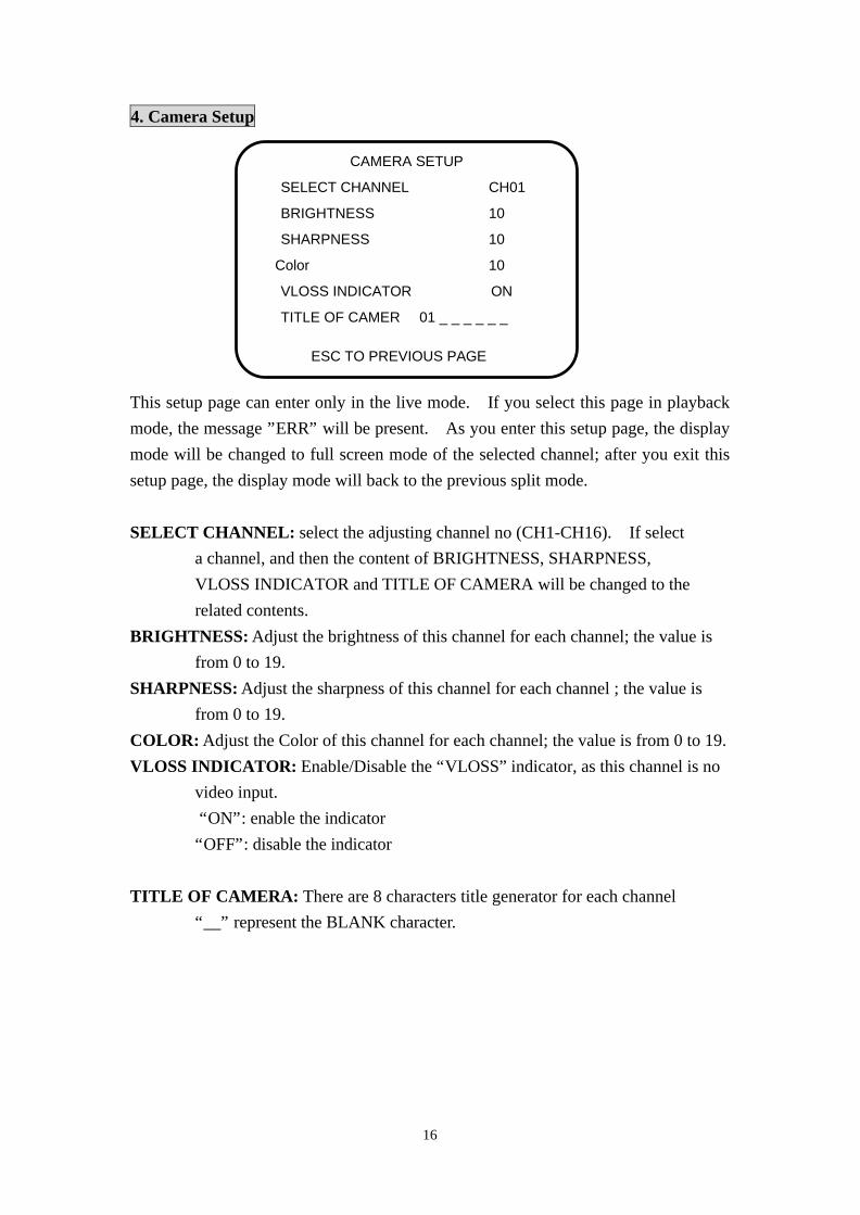
4. Camera Setup This setup page can enter only in the live mode. If you select this page in playback mode, the message ”ERR” will be present. As you enter this setup page, the display mode will be changed to full screen mode of the selected channel; after you exit this setup page, the display mode will back to the previous split mode.
SELECT CHANNEL: select the adjusting channel no (CH1-CH16). If select a channel, and then the content of BRIGHTNESS, SHARPNESS, VLOSS INDICATOR and TITLE OF CAMERA will be changed to the related contents. BRIGHTNESS: Adjust the brightness of this channel for each channel; the value is from 0 to 19. SHARPNESS: Adjust the sharpness of this channel for each channel ; the value is from 0 to 19. COLOR: Adjust the Color of this channel for each channel; the value is from 0 to 19. VLOSS INDICATOR: Enable/Disable the “VLOSS” indicator, as this channel is no video input. “ON”: enable the indicator “OFF”: disable the indicator TITLE OF CAMERA: There are 8 characters title generator for each channel “__” represent the BLANK character.
SELECT CHANNEL CH01
BRIGHTNESS 10
SHARPNESS 10
Color 10
VLOSS INDICATOR ON
TITLE OF CAMER 01 _ _ _ _ _ _
ESC TO PREVIOUS PAGE
CAMERA SETUP
17
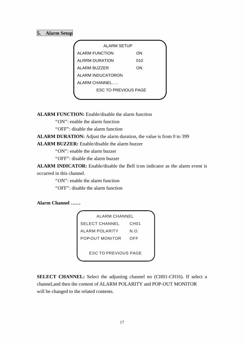
5. Alarm Setup ALARM FUNCTION: Enable/disable the alarm function “ON”: enable the alarm function “OFF”: disable the alarm function ALARM DURATION: Adjust the alarm duration, the value is from 0 to 399 ALARM BUZZER: Enable/disable the alarm buzzer “ON”: enable the alarm buzzer “OFF”: disable the alarm buzzer ALARM INDICATOR: Enable/disable the Bell icon indicator as the alarm event is occurred in this channel. “ON”: enable the alarm function “OFF”: disable the alarm function
Alarm Channel … …
ALARM CHANNEL
SELECT CHANNEL CH01
ALARM POLARITY N.O.
POP-OUT MONITOR OFF
ESC TO PREVIOUS PAGE
SELECT CHANNEL: Select the adjusting channel no (CH01-CH16). If select a channel,and then the content of ALARM POLARITY and POP-OUT MONITOR will be changed to the related contents.
ALARM SETUP
ALARM FUNCTION ON
ALRRM DURATION 010
ALARM BUZZER ON
ALARM INDUCATOR ON
ALARM CHANNEL… .. ESC TO PREVIOUS PAGE
18
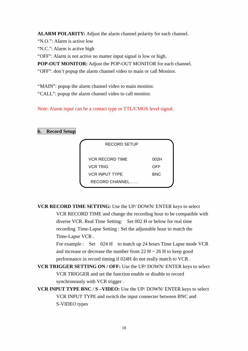
ALARM POLARITY: Adjust the alarm channel polarity for each channel. “N.O.”: Alarm is active low “N.C.”: Alarm is active high “OFF”: Alarm is not active no matter input signal is low or high. POP-OUT MONITOR: Adjust the POP-OUT MONITOR for each channel. “OFF”: don’t popup the alarm channel video to main or call Monitor. “MAIN”: popup the alarm channel video to main monitor. “CALL”: popup the alarm channel video to call monitor. Note: Alarm input can be a contact type or TTL/CMOS level signal.
6. Record Setup VCR RECORD TIME SETTING: Use the UP/ DOWN/ ENTER keys to select VCR RECORD TIME and change the recording hour to be compatible with diverse VCR. Real Time Setting: Set 002 H or below for real time recording Time-Lapse Setting : Set the adjustable hour to match the Time-Lapse VCR . For example : Set 024 H to match up 24 hours Time Lapse mode VCR and increase or decrease the number from 22 H ~ 26 H to keep good performance in record timing if 024H do not really match to VCR . VCR TRIGGER SETTING ON / OFF: Use the UP/ DOWN/ ENTER keys to select VCR TRIGGER and set the function enable or disable to record synchronously with VCR trigger . VCR INPUT TYPE BNC / S –VIDEO: Use the UP/ DOWN/ ENTER keys to select VCR INPUT TYPE and switch the input connecter between BNC and S-VIDEO types
RECORD SETUP
VCR RECORD TIME 002H
VCR TRIG OFF
VCR INPUT TYPE BNC
RECORD CHANNEL… …
19
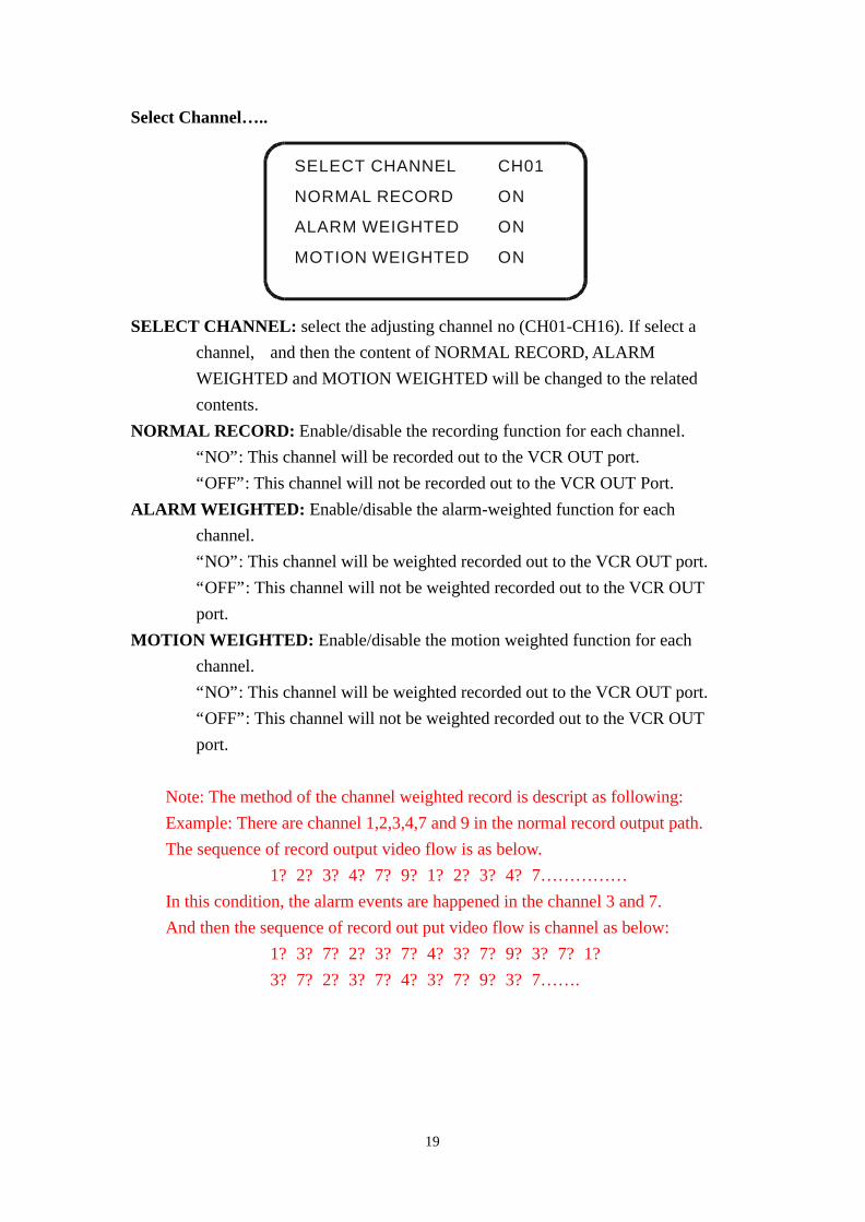
Select Channel… ..
SELECT CHANNEL CH01
NORMAL RECORD ON
ALARM WEIGHTED ON
MOTION WEIGHTED ON
SELECT CHANNEL: select the adjusting channel no (CH01-CH16). If select a channel, and then the content of NORMAL RECORD, ALARM WEIGHTED and MOTION WEIGHTED will be changed to the related contents. NORMAL RECORD: Enable/disable the recording function for each channel. “NO”: This channel will be recorded out to the VCR OUT port. “OFF”: This channel will not be recorded out to the VCR OUT Port. ALARM WEIGHTED: Enable/disable the alarm-weighted function for each channel. “NO”: This channel will be weighted recorded out to the VCR OUT port. “OFF”: This channel will not be weighted recorded out to the VCR OUT port. MOTION WEIGHTED: Enable/disable the motion weighted function for each channel. “NO”: This channel will be weighted recorded out to the VCR OUT port. “OFF”: This channel will not be weighted recorded out to the VCR OUT port.
Note: The method of the channel weighted record is descript as following: Example: There are channel 1,2,3,4,7 and 9 in the normal record output path. The sequence of record output video flow is as below.
1? 2? 3? 4? 7? 9? 1? 2? 3? 4? 7… … … … … In this condition, the alarm events are happened in the channel 3 and 7. And then the sequence of record out put video flow is channel as below:
1? 3? 7? 2? 3? 7? 4? 3? 7? 9? 3? 7? 1? 3? 7? 2? 3? 7? 4? 3? 7? 9? 3? 7… … .
20
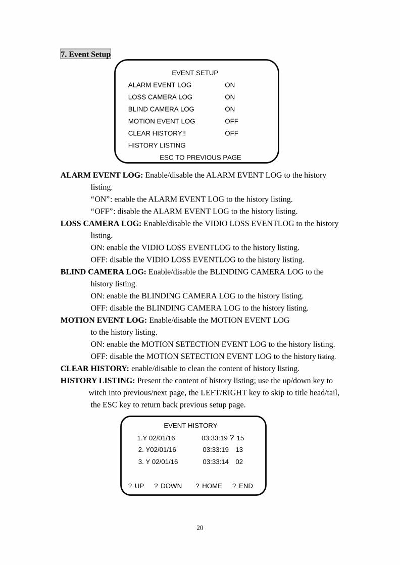
7. Event Setup ALARM EVENT LOG: Enable/disable the ALARM EVENT LOG to the history listing. “ON”: enable the ALARM EVENT LOG to the history listing. “OFF”: disable the ALARM EVENT LOG to the history listing. LOSS CAMERA LOG: Enable/disable the VIDIO LOSS EVENTLOG to the history listing. ON: enable the VIDIO LOSS EVENTLOG to the history listing. OFF: disable the VIDIO LOSS EVENTLOG to the history listing. BLIND CAMERA LOG: Enable/disable the BLINDING CAMERA LOG to the history listing. ON: enable the BLINDING CAMERA LOG to the history listing. OFF: disable the BLINDING CAMERA LOG to the history listing. MOTION EVENT LOG: Enable/disable the MOTION EVENT LOG to the history listing. ON: enable the MOTION SETECTION EVENT LOG to the history listing. OFF: disable the MOTION SETECTION EVENT LOG to the history listing. CLEAR HISTORY: enable/disable to clean the content of history listing. HISTORY LISTING: Present the content of history listing; use the up/down key to witch into previous/next page, the LEFT/RIGHT key to skip to title head/tail, the ESC key to return back previous setup page.
EVENT SETUP
ALARM EVENT LOG ON
LOSS CAMERA LOG ON
BLIND CAMERA LOG ON
MOTION EVENT LOG OFF
CLEAR HISTORY!! OFF
HISTORY LISTING
ESC TO PREVIOUS PAGE
EVENT HISTORY
1.Y 02/01/16 03:33:19 ? 15
2. Y02/01/16 03:33:19 13
3. Y 02/01/16 03:33:14 02
? UP ? DOWN ? HOME ? END
21
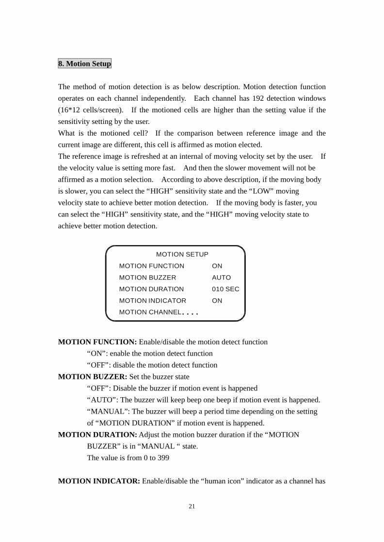
8. Motion Setup The method of motion detection is as below description. Motion detection function operates on each channel independently. Each channel has 192 detection windows (16*12 cells/screen). If the motioned cells are higher than the setting value if the sensitivity setting by the user. What is the motioned cell? If the comparison between reference image and the current image are different, this cell is affirmed as motion elected. The reference image is refreshed at an internal of moving velocity set by the user. If the velocity value is setting more fast. And then the slower movement will not be affirmed as a motion selection. According to above description, if the moving body is slower, you can select the “HIGH” sensitivity state and the “LOW” moving velocity state to achieve better motion detection. If the moving body is faster, you can select the “HIGH” sensitivity state, and the “HIGH” moving velocity state to achieve better motion detection.
MOTION SETUP
MOTION FUNCTION ON
MOTION BUZZER AUTO
MOTION DURATION 010 SEC
MOTION INDICATOR ON
MOTION CHANNEL ? ? .
MOTION FUNCTION: Enable/disable the motion detect function “ON”: enable the motion detect function “OFF”: disable the motion detect function MOTION BUZZER: Set the buzzer state “OFF”: Disable the buzzer if motion event is happened “AUTO”: The buzzer will keep beep one beep if motion event is happened. “MANUAL”: The buzzer will beep a period time depending on the setting of “MOTION DURATION” if motion event is happened. MOTION DURATION: Adjust the motion buzzer duration if the “MOTION BUZZER” is in “MANUAL “ state. The value is from 0 to 399
MOTION INDICATOR: Enable/disable the “human icon” indicator as a channel has

22
motion detection. “ON”: Enable the “human icon” indicator as a channel has motion detection. “OFF”: disable the “human icon” indicator as a channel has motion detection. Motion Channel… ..
MOTION SETUP
MOTION CHANNEL CH01
MOTION ACTIVE ON
WINDOW VISIBLE ON
SENSITIVITY HIGH
MOVING VELOCITY HIGH
MOTION AREA
SELECT CHANNEL: Select the adjusting channel no (CH01-CH16). If select a channel, and then the content of MOTION ACTIVE, WINDOW VISIBLE, SENSTIVITY and MOVING VELOCITY will be changed to the related contents. MOTION ACTIVE: Enable / disable the motion detect function for each channel. “MOTION”: Enable the motion detect function for each channel. If you
select this setting the screen will appear the 192 grids of the motion detect and the selected motion detect area. But the blind function is disable. “BLIND”: Enable the blind function for each channel. If you select this setting, the screen will appear the blind icon as the blind event is happened. “MD+BL”: Enable the Motion Detect and blind function. “OFF”: disable motion detect function and blind function for each channel. If you select this “OFF” state, the screen will discard all of the motion detect area, but still show the grids of the motion detect, and the blind icon will not appear in the screen as the blind event is happened.
WINDOW VISIBLE: Visible / invisible the motion detect area.
(This switch don’t affect the state of the motion detect for each channel) “ON”: Visible the motion detect area for each channel, If you select this
23
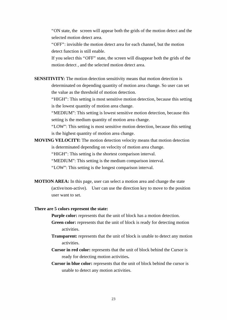
“ON state, the screen will appear both the grids of the motion detect and the selected motion detect area. “OFF”: invisible the motion detect area for each channel, but the motion detect function is still enable. If you select this “OFF” state, the screen will disappear both the grids of the motion detect , and the selected motion detect area. SENSITIVITY: The motion detection sensitivity means that motion detection is determinated on depending quantity of motion area change. So user can set the value as the threshold of motion detection. “HIGH”: This setting is most sensitive motion detection, because this setting is the lowest quantity of motion area change. “MEDIUM”: This setting is lowest sensitive motion detection, because this setting is the medium quantity of motion area change. “LOW”: This setting is most sensitive motion detection, because this setting is the highest quantity of motion area change. MOVING VELOCITY: The motion detection velocity means that motion detection is determinated depending on velocity of motion area change. “HIGH”: This setting is the shortest comparison interval. “MEDIUM”: This setting is the medium comparison interval. “LOW”: This setting is the longest comparison interval. MOTION AREA: In this page, user can select a motion area and change the state (active/non-active). User can use the direction key to move to the position user want to set. There are 5 colors represent the state: Purple color: represents that the unit of block has a motion detection. Green color: represents that the unit of block is ready for detecting motion activities. Transparent: represents that the unit of block is unable to detect any motion activities. Cursor in red color: represents that the unit of block behind the Cursor is ready for detecting motion activities. Cursor in blue color: represents that the unit of block behind the cursor is unable to detect any motion activities.

24
9. Remote Setup REMOTE BAUD RATE: 2400 / 4800 / 9600 / 19200
MACHINE ADDRESS ID: Use the UP/DOWN/ENTER keys to set the Address ID of this machine. In the whole system architecture, the value is range from 01 to 16.
MACHINE NAME: There are 5 character spaces to hold the name. PORT 1 DEVICE TYPE: This switch define which device the port 1 (RS485)
is connecting. The default is KEYB (REMOTE KEYBOARD) PORT 2 DEVICE TYPE: This switch define which device the port 2 (RS485)
is connecting. The default is LILIN (LILIN’S FAST DOME) PORT CROSS LINK: This switch is setting whether both the PORT 1 & PORT
2 are cross connected? “ON”: Both PORT 1 & PORT 2 are connected. The Multiplex can use PORT 1 to connect one Remote Keyboard and one kind of Fast Dome via PORT 2 bus, and it can be controlled by this Remote Keyboard, but it cannot connect any Fast Dome in the PORT 1 bus. In this architecture you can install multiple keyboard via PORT 1 bus. “OFF”: Both PORT 1 & PORT 2 are not cross connected. The multiplex can use PORT 1 to connect one Remote Keyboard and one kind of fast Dome via PORT 1 bus, and both the mux and fast Dome can be controlled by the Remote keyboard, on the same bus, but not the fast Dome at the other side. In This architecture, the multiplex can also install another keyboard and another kind of fast Dome via PORT 2 bus, and it can be controlled by this Keyboard on the same bus.
REMOTE SETUP
REMOTE BAUD RATE 9600
MACHINE ADDRESS ID 01
MACHINE NAME MUX_ _
PORT 1 DEVICE TYPE KEYB
PORT 2 DEVICE TYPE LILIN
PORT CROSS LINK ON
PORT CROSS LINK ON
25
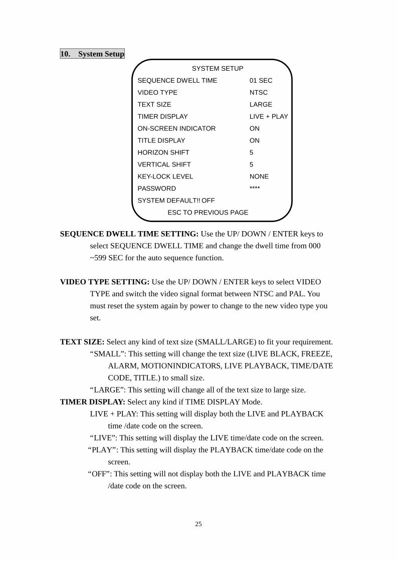
10. System Setup SEQUENCE DWELL TIME SETTING: Use the UP/ DOWN / ENTER keys to select SEQUENCE DWELL TIME and change the dwell time from 000 ~599 SEC for the auto sequence function. VIDEO TYPE SETTING: Use the UP/ DOWN / ENTER keys to select VIDEO TYPE and switch the video signal format between NTSC and PAL. You must reset the system again by power to change to the new video type you set. TEXT SIZE: Select any kind of text size (SMALL/LARGE) to fit your requirement. “SMALL”: This setting will change the text size (LIVE BLACK, FREEZE, ALARM, MOTIONINDICATORS, LIVE PLAYBACK, TIME/DATE CODE, TITLE.) to small size. “LARGE”: This setting will change all of the text size to large size. TIMER DISPLAY: Select any kind if TIME DISPLAY Mode. LIVE + PLAY: This setting will display both the LIVE and PLAYBACK time /date code on the screen. “LIVE”: This setting will display the LIVE time/date code on the screen. “PLAY”: This setting will display the PLAYBACK time/date code on the screen. “OFF”: This setting will not display both the LIVE and PLAYBACK time /date code on the screen.
SYSTEM SETUP
SEQUENCE DWELL TIME 01 SEC
VIDEO TYPE NTSC
TEXT SIZE LARGE
TIMER DISPLAY LIVE + PLAY
ON-SCREEN INDICATOR ON
TITLE DISPLAY ON
HORIZON SHIFT 5
VERTICAL SHIFT 5
KEY-LOCK LEVEL NONE
PASSWORD ****
SYSTEM DEFAULT!! OFF
ESC TO PREVIOUS PAGE
26
TITEL DISPLAY: Enable/disable the camera title display function “ON”: enable the title of camera displayed on the screen. “OFF”: disable the display function. ON-SCREEN INDICATOR: “ON”: This setting will display the indicator (LIVE, PLAYBACK, FREEZE) “OFF”: This setting will not display the indicator (LIVE, PLAYBACK, FREEZE) HORIZON SHIFT: Adjust the position of the whole screen in the horizontal direction. The value is from 0 to 9. VERTICAL SHIFT: Adjust the position of the whole screen in the vertical direction. The value is from 0 to 9. KEY-LOCK LEVEL: Setting the priority of user operation NONE: NO user priority setting
PARTIAL: At this setting, user is just capable of all hot keys except both the MENU and VCR/LIVE keys. If user presses this two keys. The password dialog is popup. In this time, user need to key in the password for entering the operation. ALL: At this setting, user cannot operate any key, if user press any key of the password dialog is popup. In this time, user need to key in the password for entering the operation.
PASSWORD: The default password is “1234”
IF you want to change the password, please use the channel number key 1~9 (it is represent numerical 1~9)
SYSTEM DEFAULT SETTING: Use the UP/ DOWN / ENTER keys to select SYSTEM DEFAULT and ESC key make the system to be restored the default parameters before shipped.