150/5220-20a, airport snow and ice control equipment… · 2014-10-02 · snow and ice control. for...
TRANSCRIPT

U.S. Department of Transportation
Federal Aviation Administration
Advisory Circular
Subject: Airport Snow and Ice Control Equipment
Date: 9/24/2014 Initiated by: AAS-100
AC No: 150/5220-20A Change:
1. Purpose. This advisory circular (AC) provides guidance to assist airport operators in the procurement of snow and ice control equipment for airport use.
2. Cancellation. This AC cancels AC 150/5220-20, dated 6/30/1992.
3. Vehicle movement coordination. At certificated airports, vehicle operations in the movement and non-movement areas must be conducted in accordance with Title 14 Code of Federal Regulations (CFR) Part 139.329, Pedestrians and Ground Vehicles, and appropriate provisions of AC 150/5200-30, Airport Winter Safety and Operations. The information in this AC should be used to develop a Snow and Ice Control Plan (SICP) per 14 CFR Part 139.313 Snow and Ice Control. For guidance, specification and standards for painting, marking, and lighting of vehicles operating in the airport air operations area (AOA), refer to the latest edition of AC 150/5210-5, Painting, Marking, and Lighting of Vehicles Used on an Airport. The use of AC 150/5210-5 is mandatory for vehicles purchased with federal grant monies through the Airport Improvement Program (AIP) and/or with revenue from the Passenger Facility Charge Program (PFC). To help minimize the potential for runway incursions, see Airport Cooperative Research Program (ACRP) Synthesis #12, Preventing Vehicle – Aircraft Incidents during Winter Operations and Periods of Low Visibility, ACRP Synthesis #29, Ramp Safety Practices and AC 150/5210-20, Ground Vehicle Operations on Airports, for guidance in the areas of but not limited to communications, fatigue, and operational protocols.
4. Application. The Federal Aviation Administration (FAA) recommends the standards and other guidance in this AC for use in the purchase of snow removal and ice control equipment. In general, use of this AC is not mandatory. Certificated airports may use the standards and recommendations contained in this AC to satisfy specific requirements of 14 CFR Part 139, Certification of Airports, Subparts C (Airport Certification Manual) and D (Operations). Use of this AC is mandatory for all projects funded with federal grant monies through the AIP and/or with revenue from the PFC Program. See Grant Assurance No. 34, Policies, Standards, and Specifications, and PFC Assurance No. 9, Standards and Specifications.
5. Principal Changes.
a. Reconfigured this AC to present the relationship between AC 150/5200-30 and this AC when determining the types of snow equipment and the number of such types to clear Priority 1 paved areas.

AC 150/5220-20A 9/24/2014
b. This AC now references industry consensus specifications by the Society of Automotive Engineers (SAE) G15, Airport Snow and Ice Control Equipment Committee. Previously, the FAA wrote its own specifications. This AC notes a few pieces of snow removal equipment (SRE), for example, liquid deicer spreaders, for which SAE has not yet finalized their draft specifications. However once SAE publishes their specifications for such equipment, this advisory circular may also reference those specifications.
6. Use of metric units. Throughout this AC, U.S. customary units are used followed with “soft” (rounded) conversion to metric units. The U.S. customary units govern.
Michael J. O’Donnell Director of Airport Safety and Standards
ii

9/24/2014 AC 150/5220-20A
TABLE OF CONTENTS
Chapter 1. Overview ................................................................................................................ 1 1-1. Background. ............................................................................................................ 1 1-2. Classification of snow and ice control equipment. ................................................. 2 1-3. Selection process. .................................................................................................... 2 1-4. Runway friction testing equipment. ........................................................................ 3 1-5. In-pavement temperature sensors and mobile pavement temperature sensors. ...... 3 1-6. Automated Weather Support for Deicing Decision Making (WSDDM) system. .. 3 1-7. Use of SAE ARP specifications. ............................................................................. 3 1-8. Variable use of equipment. ..................................................................................... 3 1-9. Certification. ........................................................................................................... 3
Chapter 2. Selection Process for Various Snow Removal and Ice Control Equipment .... 5 2-1. Selection process. .................................................................................................... 5 2-2. Step 1 - determination of Priority 1 paved areas. .................................................... 5 2-3. Minimum snow removal and ice control equipment requirements. ....................... 8 2-4. Selecting a high-speed rotary plow for commercial and non-commercial service
airports. ................................................................................................................. 10 2-5. Selecting a snow plow cutting edge (length) for commercial and non-commercial
service airports. ..................................................................................................... 15 2-6. Selecting a dry material spreader. ......................................................................... 21 2-7. Selecting a liquid material spreader. ..................................................................... 25 2-8. Selecting a runway broom with airblast................................................................ 25
Chapter 3. High-Speed Rotary Plows................................................................................... 27 3-1. Description. ........................................................................................................... 27 3-2. High-speed rotary plow capacities. ....................................................................... 27 3-3. SAE ARP equipment specification for high-speed rotary plows. ......................... 27
Chapter 4. Snow Plows .......................................................................................................... 31 4-1. Description. ........................................................................................................... 31 4-2. Snow plow uses..................................................................................................... 31 4-3. SAE ARP equipment specification for snow plows and carrier vehicles. ............ 32
Chapter 5. Material Spreaders ............................................................................................. 35 5-1. Description. ........................................................................................................... 35 5-2. Types of material spreaders. ................................................................................. 35 5-3. SAE ARP equipment specification for material spreaders. .................................. 36
Chapter 6. Runway Brooms .................................................................................................. 39 6-1. Description. ........................................................................................................... 39 6-2. Types of runway brooms. ..................................................................................... 39 6-3. Classification......................................................................................................... 39 6-4. SAE ARP equipment specification for runway brooms with airblast. ................. 40
iii

AC 150/5220-20A 9/24/2014
Chapter 7. Types of Carrier Vehicles ................................................................................... 45 7-1. Description. ........................................................................................................... 45 7-2. Carrier vehicle dimensions. .................................................................................. 46 7-3. Outdoor storage of carrier vehicles. ...................................................................... 46 7-4. SAE ARP equipment specification for MTE dedicated carrier vehicles. ............. 46
Chapter 8. Operational Standards and Compliance Testing ............................................. 51 8-1. General. ................................................................................................................. 51 8-2. Required carrier vehicle tests. ............................................................................... 51 8-3. High-speed rotary plow test. ................................................................................. 52 8-4. Snow plow test. ..................................................................................................... 52 8-5. Dry and liquid material spreader tests. ................................................................. 53 8-6. Runway brooms with airblast. .............................................................................. 53
Appendix 1. Specification for Carrier Vehicle ......................................................................... 55
Appendix 2. Optional/Alternate Equipment Specification ..................................................... 57
Appendix 3. High-Speed Rotary Plow Specification ............................................................... 61
Appendix 4. Snow Plow Specification ....................................................................................... 63
Appendix 5. Material Spreader Specification .......................................................................... 65
Appendix 6. Runway Broom with Airblast Specification ....................................................... 69
LIST OF FIGURES
Figure 1–1. Airport snow and ice control equipment ..................................................................... 1 Figure 2–1. Example of determined prioritized paved areas based on AC 150/5200-30 ............... 6 Figure 2–2. Priority 1 paved area example ..................................................................................... 7 Figure 2–3. High-speed rotary plow calculations for airports with commercial service .............. 13 Figure 2–4. High-speed rotary plow calculations for airports with non-commercial service ...... 14 Figure 2–5. Snow removal (tons/hr) for Priority 1 paved areas for commercial service airports 16 Figure 2–6. Snow removal (tons/hr) for Priority 1 paved areas for non-commercial service
airports ....................................................................................................................... 17 Figure 2–7. Effective snow plow blade length related to snow displacement .............................. 19 Figure 2–8. Effective versus actual snow plow blade length ........................................................ 20 Figure 2–9. Hopper capacity – sand ............................................................................................. 23 Figure 2–10. Hopper capacity – urea ............................................................................................ 24 Figure 3–1. Single-stage rotary plow ............................................................................................ 28 Figure 3–2. Two-stage rotary plow ............................................................................................... 28 Figure 3–3. Typical rotary plow types .......................................................................................... 29 Figure 4–1. Snow plow components ............................................................................................. 33 Figure 4–2. Different types of snow plows ................................................................................... 34
iv

9/24/2014 AC 150/5220-20A
Figure 5–1. Dry material spreader types ....................................................................................... 37 Figure 5–2. Example of one design and component layout of a dry material spreader ................ 38 Figure 6–1. Typical runway brooms ............................................................................................. 41 Figure 6–2. Towed type runway broom ........................................................................................ 42 Figure 6–3. Common types of broom bristles used on airports .................................................... 43
LIST OF TABLES
Table 2-1. Itemized Priority 1 paved areas ..................................................................................... 8 Table 2-2. Equipment selection criteria for non-commercial service airports ................................ 9 Table 2-3. High-speed rotary plow performance .......................................................................... 10 Table 2-4. Determining the class and number of high-speed rotary plows .................................. 12 Table 2-5. Weight to volume relationship of sand and urea ......................................................... 22 Table 7-1. MTE specification selections ...................................................................................... 47
v

AC 150/5220-20A 9/24/2014
This page intentionally left blank.
vi

9/24/2014 AC 150/5220-20A
Chapter 1. Overview
Figure 1–1. Airport snow and ice control equipment
1-1. Background.
Airport operators should maintain runways and taxiways if possible to a “no worse than wet” (i.e., no contaminant accumulation) condition during winter storms. To meet this challenge, the purchase of snow and ice control equipment will not only require significant financial commitments, but also require careful planning. This advisory circular (AC) provides airport operators a selection process for snow removal and ice control equipment like those shown in Figure 1-1.
a. Selection process. The selection process involves three components: (1) identifying the type of equipment for a specific task, (2) determining the number of such equipment, and (3) using the recommended equipment specification to better ensure the equipment performs the required task.
b. Selection components. The first component uses the appendices in this AC that provide a general template of what task the desired equipment should perform and other relative operational information. The second component requires the airport operator to determine: (1) the total square footage of the critical paved areas of the airfield and supporting paved facilities, such as areas required by the airport rescue and fire fighting service, necessary for viable and safe aircraft operations during winter storm events, and (2) the airport’s classification as either a commercial service airport or a non-commercial service airport. The selection of some equipment will require additional computations to determine the number of such equipment,
1

AC 150/5220-20A 9/24/2014
such as high-speed rotary plows and snow plows. In these cases, this AC provides graphical tables to make such computations. The third component is based, to a large extent, on manufacturer equipment specifications. However, to minimize the amount of variation among the various pieces of equipment and carrier vehicles to perform specific tasks, this AC references Aerospace Recommended Practice (ARP) specifications for snow and ice control equipment that were developed by the Society of Automotive Engineers (SAE), Aerospace Division.
c. Federal Aviation Administration (FAA) equipment goal. This AC references SAE ARPs to facilitate the purchase by airport operators of standard equipment that has been tested and certified by the manufacturer to meet the intended performance and quality of product acceptable to the FAA.
1-2. Classification of snow and ice control equipment.
This AC classifies snow and ice control equipment according to the specific task(s) that the equipment is designed to perform.
a. This AC discusses high-speed rotary plows, snow plows, solid and liquid material spreaders, runway brooms with air blast, and carrier vehicles (the prime movers for such equipment). Find the definition for each equipment, their components, and performance measures in the referenced SAE ARP equipment specifications.
b. Chapter 7 describes the most common types of carrier vehicles used by today’s industry. This AC categorizes carrier vehicles as either conventional carrier vehicles or dedicated carrier vehicles. This categorization is made to identify those multi-task carrier vehicles built with the capability to perform three integrated functions, namely snowplowing, brooming, and airblasting at a speed of at least 30 mph (48 km/h). Industry refers to these carrier vehicles as high-speed multi-task equipment (MTE), as defined by SAE ARP 5548, Multi-Tasking Equipment (MTE) for Airfield Snow Removal High Speed, Multi-Tasking Snow Removal Unit to include Carrier Vehicle, Snow Plow, Rotary Broom High Velocity Air.
1-3. Selection process.
a. Step 1 - The first step is for the airport operator to determine the total square footage of the critical paved areas of the airfield and supporting paved facilities, such as paved areas required by the airport rescue and fire fighting service, necessary for viable and safe aircraft operations during winter storms. This critical paved area establishes the “Priority 1” response effort for the airport operator. Find guidance for prioritizing paved areas and facilities in AC 150/5200-30.
b. Step 2 - Once the Priority 1 paved area is designated, the airport operator should determine the Airfield Clearance Time from AC 150/5200-30 according to the airport’s classification as either a commercial service airport or a non-commercial service airport. The classification establishes a specified clearance time for the Priority 1 paved area to be cleared for a range of annual airplane operations. The intent of Step 2 is for an airport operator to have a sufficient amount of snow removal and ice control equipment to clear 1 inch (2.5 cm) of snow weighing up to 25 lbs/ft³ (400 kg/m³) from Priority 1 areas within a reasonable time to accommodate the documented annual airplane operations.
2

9/24/2014 AC 150/5220-20A
c. Chapter 2 - Provides examples of this process for the various equipment.
d. Final step – equipment specification(s) - After determining the type of snow removal and ice control equipment, the airport operator should use the recommended specifications provided by this AC to develop bid packages.
1-4. Runway friction testing equipment.
Find specifications for friction testing equipment used to conduct runway friction surveys during winter operations in AC 150/5200-30 and AC 150/5320-12, Measurement, Construction, and Maintenance of Skid-Resistant Airport Pavement Surfaces.
1-5. In-pavement temperature sensors and mobile pavement temperature sensors.
Find specifications for in-pavement temperature sensors and mobile pavement temperature sensors in AC 150/5200-30.
1-6. Automated Weather Support for Deicing Decision Making (WSDDM) system.
Find the specification for WSDDM systems in AC 150/5200-30.
1-7. Use of SAE ARP specifications.
Use SAE ARP equipment specifications referenced in this AC individually or in combination with one another. For example, an airport operator desiring to acquire a self-propelled high-speed rotary plow can use a single SAE ARP specification that prescribes both the high-speed rotary plow and the carrier vehicle within the same specification. On the other hand, an airport operator desiring to acquire a snow plow carrier vehicle with a snow plow, plus a towed-behind airport broom with air blast would use more than one SAE ARP specification. The appendices in this AC assist the airport operator in the bid purchasing process of the various pieces of equipment.
1-8. Variable use of equipment.
Depending upon winter conditions, a snow plow supported by a runway broom may be all that is required to keep an airport open to traffic. Other airports may need more diverse equipment to combat more severe winter conditions. In assessing airport needs, the airport operator must compare the cost/benefit relationship of acquiring a multi-functional piece of equipment offering a number of attachments versus the acquisition of single units, each designed primarily to accomplish one task.
1-9. Certification.
Purchasers of equipment described in this AC should obtain a certification in writing from the manufacturer/vendor that the components constituting the whole of the equipment being supplied to the airport operator comply with the applicable performance, design, and construction requirements of the referenced specification. This certification is mandatory if the equipment is purchased with federal funds under the Airport Improvement Program (AIP) or approved under
3

AC 150/5220-20A 9/24/2014
the Passenger Facility Charges (PFC) Program. In both events, a signed copy of the certification must be made part of the equipment documentation.
4

9/24/2014 AC 150/5220-20A
Chapter 2. Selection Process for Various Snow Removal and Ice Control Equipment
2-1. Selection process.
This chapter explains the selection process for snow removal and ice control equipment which commences with Step 1, the determination of the total Priority 1 paved area. As previously stated, some of the equipment is determined using only the first step while the remaining equipment follows a 2-step process. Both steps apply the same assumption to remove 1 inch (2.5 cm) of snow weighing up to 25 lbs/ft³ (400 kg/m³) from the Priority 1 paved area within a specified time for the airport’s annual airplane operations (based on its classification as a commercial service airport or non-commercial service airport). Furthermore, this AC applies an equipment efficiency factor equal to 70 percent. This assumption takes into account the need by such equipment to slow down and to change course (for example, approaching the end of a runway to reverse course), back-and-forth clearing operations common on stub taxiways and connector taxiways, and to account for slight snow spillage, slight overlapping of clearing operations, and poor visibility driving conditions. Lastly, the chapter familiarizes the airport operator in the use of the graphs and tables required by the 2-step process for determining the number of high-speed rotary plows and snow plows. Practical examples illustrate the full selection process.
2-2. Step 1 - determination of Priority 1 paved areas.
Figure 2–1 illustrates how to determine the total Priority 1 paved area using AC 150/5200-30.
5

AC 150/5220-20A 9/24/2014
Figure 2–1. Example of determined prioritized paved areas based on AC 150/5200-30
It is important to recognize that the airport operator determines which critical paved areas are adequate for viable and safe aircraft operations during winter storm events. Figure 2–2 illustrates where it was determined that not all taxi routes needed plowing as Priority 1 areas.
6
9/24/2014 AC 150/5220-20A
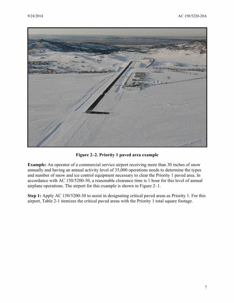
Figure 2–2. Priority 1 paved area example
Example: An operator of a commercial service airport receiving more than 30 inches of snow annually and having an annual activity level of 35,000 operations needs to determine the types and number of snow and ice control equipment necessary to clear the Priority 1 paved area. In accordance with AC 150/5200-30, a reasonable clearance time is 1 hour for this level of annual airplane operations. The airport for this example is shown in Figure 2–1.
Step 1: Apply AC 150/5200-30 to assist in designating critical paved areas as Priority 1. For this airport, Table 2-1 itemizes the critical paved areas with the Priority 1 total square footage.
7

AC 150/5220-20A 9/24/2014
Table 2-1. Itemized Priority 1 paved areas
Critical Priority 1 paved areas to be cleared
Location Paved Area (square feet)
Main runway (9000 ft × 150 ft) 1,350,000 Parallel taxiways (9000 ft × 75 ft) 675,000 4 taxiway/runway connectors 107,812 Taxiway fillets 20,000 Airport Rescue and Fire Fighting (ARFF) station apron, emergency roads, identified ARFF mutual aid access point(s), and de-icing facilities
20,000
Terminal apron 600,000 Centralized aircraft deicing facility (northside) 259,000 TOTAL Priority 1 paved area to be cleared 3,031,812
Note: The ARFF area requires the region in front of the ARFF facility clear to provide for the unobstructed exit/entry for ARFF vehicles regardless of the square footage of the given paved area. For equipment selection purposes, the paved area may be rounded upwards to 3,100,000 ft2 (288,150 m2). For runways with navigation aids (NAVAID), see AC 150/5200-30 for requirements on how to determine the snow clearance area to be maintained.
2-3. Minimum snow removal and ice control equipment requirements.
Base the required minimum types and number of snow removal and ice control equipment on several factors. Two parameters, namely the total square footage of the Priority 1 paved area and the airport’s service classification, determine the types and number of runway brooms, solid material spreaders, and liquid material spreaders. On the other hand, selection of high-speed rotary plows and snow plows requires the parameter of tonnage of snow to be removed in a given time in addition to other parameters required by the equipment.
For example:
1. What is the minimum casting distance of removed snow from the high-speed rotary plow?
2. What is the angle of attack of the snow plow’s cutting edge relative to the direction of travel?
3. If snow plows support a high-speed rotary plow, what is the operational speed of the clearing operation?
Because high-speed rotary plows dictate the general clearing operation, supportive snow plows are selected with the condition that they match the speed and the snow removal capacity (tonnage per hour) of the high-speed rotary plow. The selection of some types of winter-related equipment is not based on any of these parameters. For example, runway friction testers and in-pavement temperature sensors provide information about runway surface characteristics before and after clearing operations or/and the completion of sand or deicing/anti-icing chemical applications.
8

9/24/2014 AC 150/5220-20A
a. Commercial service airports. For commercial service airports that provide scheduled air carrier service, at least one high-speed rotary plow is recommended. Supplement this high-speed rotary plow with at least two snow plows having equal snow removal capacity. In addition to this tandem grouping, for each 750,000 ft2 (70,000 m2) of pavement area declared as Priority 1, one towed or self-propelled runway broom with air-blast and one solid material spreader for sand and/or one for applying solid deicing/anti-icing chemicals is recommended. If a liquid deicing/anti-icing chemical is used in lieu of, or in addition to, a solid deicing/anti-icing chemical, a minimum of one liquid deicing/anti-icing chemical spraying vehicle is recommended. Paragraphs 2-4 and 2-5 provide the selection criteria to determine the number and types of high-speed rotary plows and snow plows by using a second step.
b. Non-commercial service airports. For non-commercial service airports with over 10,000 operations and at least 15 inches (38 cm) of annual snowfall should have a minimum of one high-speed rotary plow supported by two snow plows of equal snow removal capacity. For non-commercial service airports with over 10,000 operations that experience an annual snowfall of less than 15 inches (38 cm), provide a minimum of one snow plow. For non-commercial service airports having 10,000 or fewer annual operations that experience more than 30 inches (76 cm) of annual snowfall, provide a minimum of one high-speed rotary plow supported by two snow plows of equal snow removal capacity. For non-commercial service airports having 10,000 or fewer annual operations that experience an annual snowfall of 30 inches (76 cm) or less, provide a minimum of one snow plow. Table 2-2 illustrates these selection criteria. Paragraphs 2-4 and 2-5 provide the selection criteria to determine the number and types of high-speed rotary plows and snow plows by using a second step.
Table 2-2. Equipment selection criteria for non-commercial service airports
Minimum high-speed rotary plow and snow plow for non-commercial Service Airports
Annual Operations Annual Snowfall (inches)
Minimum type and number of equipment
10,000 or fewer 30 inches (76 cm) or less
1 snow plow
more than 30 inches (76 cm) 1 high-speed rotary plow supported by 2 snow plows
over 10,000 15 inches (38 cm) or more 1 high-speed rotary plow supported by 2 snow plows
Less than 15 inches (38 cm) 1 snow plow
Note: Read table from left to right to determine the minimum type and number of plow equipment.
c. Other supporting equipment. Other types of supporting equipment such as front wheel loaders or ice-melters may be needed to assist in the removal of snow from all non-critical, remaining operational areas including secondary taxiways or low priority ramp aprons. AC 150/5200-30 classifies such paved areas as Priority 2 or Priority 3 areas.
9

AC 150/5220-20A 9/24/2014
2-4. Selecting a high-speed rotary plow for commercial and non-commercial service airports.
Use high-speed rotary plows, also called “rotaries” or “snowblowers,” to cast heavy concentrations of plowed snow away from movement areas such as runways and taxiways. The selected high-speed rotary plow(s) should be capable of removing the volume of snow from the Priority 1 paved area with a pre-determined casting distance to comply with runway and taxiway snow bank clearance criteria in AC 150/5200-30. This equipment, which may be self-propelled or attached to a conventional carrier vehicle, uses either one or more rotating elements (single or two-stage units) to disaggregate a snowpack. The disaggregated snow is then broken into particles small enough to pass through a casting mechanism having a directional chute. Because of their large capacity, self-propelled high-speed rotary plows are frequently required at medium to large airports while high-speed rotary plows attached to a conventional carrier vehicle may be more appropriate at smaller facilities or facilities whose climate is less severe. Table 2-3 shows the various classes of high-speed rotary plows in terms of minimum casting distance and removal capacity in tons/hour. Measure the casting distance from the longitudinal centerline of the snow removal unit to the center of mass within the perimeter of the cast pattern.
Table 2-3. High-speed rotary plow performance
High-Speed Rotary Plows Size Class Minimum Casting
Distance Feet (m)
Minimum Capacity Tons/hour
(metric tons/hour) Small I 50 (15) Up to 600 (550) Medium II 75 (23) 1500 (1360) Intermediate III 100 (31) 2500 (2270) Large IV 100 (31) 3000 (2730) Very Large V 100 (31) 4000 (3640)
150 (46) 3000 (2730) Extra Large VI 100 (31) 5000 (4550) or more
Example (continued): The operator of the same commercial service airport wants to acquire a high-speed rotary plow(s) for the upcoming winter season. For non-commercial service airports, follow the same procedure.
Determine the size and number of high-speed rotary plows needed based on the following airport conditions:
• Annual activity level equals 35,000 operations with a reasonable clearance time of 1 hour for the total Priority 1 paved area.
• Accumulated snow on the runway and taxiways are to be cast at least 100 feet from the rotary when it travels along paved edge. This casting distance sets equipment selection Criterion 1.
10
9/24/2014 AC 150/5220-20A
• Average runway operating speed of the rotary plow unit is at least 25 mph (40 km/h) to meet the reasonable clearance time of 1 hour and annual airplane operation rate. Note: this illustrative operating speed is higher than normally used for smaller airports.
• Typical snow density is 25 lbs/ft3 (400 kg/m3).
GRAPHICAL SOLUTION
Step 1. Determine the total critical paved area for Priority 1. From paragraph 2-2, Priority 1 was determined as PA = 3,100,000 ft2 (290,000 m2).
Step 2. Use of graphs. Use either Figure 2–3 or Figure 2–4.
Since this example is a commercial service airport, apply Figure 2–3. Enter the graph from the horizontal axis labeled “Square feet of Priority 1 area” with PA = 31 (3,100,000 ft2) and proceed vertically until you intersect the appropriate reference line labeled “10,000 but less than 40,000 annual operations.”
Upon locating this reference line, proceed to the left to intersect the vertical axis which reads “Snow tons per hour × 1000.” This intersection determines the tonnage (volume) of snow to be removed from the total Priority 1 paved area within the reasonable clearance time of 1 hour. In this example, the removal rate = 4,600 tons per hour. The removal rate sets equipment selection Criterion 2.
Equipment selection: Using the same figure, continue proceeding to the left of the figure with 4,600 tons per hour to pre-select among the various classes of rotary plows and their number. As seen, Class I rotary plows are too small, while a single Class VI rotary plow exceeds the removal rate of 4,600 tons per hour. Table 2-4 (read from left to right) summarizes the selection possibilities that account for Criterion 1 (the required casting distance of at least 100 feet) and Criterion 2 (removal rate of 4,600 tons per hour) to arrive at a final determination.
11
AC 150/5220-20A 9/24/2014
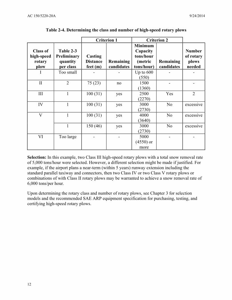
Table 2-4. Determining the class and number of high-speed rotary plows
Criterion 1 Criterion 2
Class of high-speed
rotary plow
Table 2-3 Preliminary
quantity per class
Casting Distance feet (m)
Remaining candidates
Minimum Capacity tons/hour (metric
tons/hour) Remaining candidates
Number of rotary
plows needed
I Too small - - Up to 600 (550)
- -
II 2 75 (23) no 1500 (1360)
- -
III 1 100 (31) yes 2500 (2270)
Yes 2
IV 1 100 (31) yes 3000 (2730)
No excessive
V 1 100 (31) yes 4000 (3640)
No excessive
1 150 (46) yes 3000 (2730)
No excessive
VI Too large - - 5000 (4550) or
more
- -
Selection: In this example, two Class III high-speed rotary plows with a total snow removal rate of 5,000 tons/hour were selected. However, a different selection might be made if justified. For example, if the airport plans a near-term (within 5 years) runway extension including the standard parallel taxiway and connectors, then two Class IV or two Class V rotary plows or combinations of with Class II rotary plows may be warranted to achieve a snow removal rate of 6,000 tons/per hour.
Upon determining the rotary class and number of rotary plows, see Chapter 3 for selection models and the recommended SAE ARP equipment specification for purchasing, testing, and certifying high-speed rotary plows.
12

9/24/2014 AC 150/5220-20A
Figure 2–3. High-speed rotary plow calculations for airports with commercial service
13

AC 150/5220-20A 9/24/2014
Figure 2–4. High-speed rotary plow calculations for airports with non-commercial service
14

9/24/2014 AC 150/5220-20A
2-5. Selecting a snow plow cutting edge (length) for commercial and non-commercial service airports.
Snow plows consist of a cutting edge to shear snow from the pavement, and a moldboard to lift and cast the dislodged snow to the side of the cleared path. The cutting edge may ride in contact with the pavement or be held a small distance above it by means of shoes or caster wheels. A complete snow plow unit consists of the snow plow, a carrier vehicle (conventional or dedicated), hitch, and other accessories (see Figure 4-1). Chapter 4 classifies snow plow sizes. The following selection process determines the overall length of the cutting edge, termed “actual cutting edge.” With the exception of bullnose clearing operations, the cutting edge is tilted to produce smaller cleared paths than bullnosing. This reduction in the actual length of the cutting edge is referred to as the “effective cutting edge.” Note: The process of selecting a snow plow cutting edge is not an exact science and different manufacturers may suggest alternative selection approaches tailored to their blade types and equipment. The results should be essentially the same.
Example (continued): The operator of the same commercial service airport wants to acquire snow plow(s) to support the high-speed rotary plows for the upcoming winter season.
Determine the actual length of the total cutting edge and number of carrier vehicles necessary. Base the determination on the following airport conditions:
• Annual activity level equals 35,000 operations with a reasonable clearance time of 1 hour for the total Priority 1 paved area.
• Average runway operating speed of the snow plow unit is at least 25 mph (40 km/h) to meet the reasonable clearance time of 1 hour and annual airplane operation rate. Note: this illustrative operating speed is higher than normally used for smaller airports.
• Typical snow density is 25 lbs/ft3 (400 kg/m3) – the industry accepted standard. • Cutting angle of the blade will be set at 35 degrees. • The efficiency of the snow plow matches the high-speed rotary plow at 70 percent.
GRAPHICAL SOLUTION
Step 1: Determine the total critical paved area for Priority 1. From paragraph 2-2, Priority 1 was determined as Q = 3,100,000 ft2 (290,000 m2).
Step 2: Use of graphs (three graphs are used). Start with Figure 2–5 to determine the tonnage of snow removal per hour. Follow the same procedure for non-commercial service airports by using Figure 2–6.
Enter the graph from the horizontal axis labeled “Priority 1 Paved Area” with PA = 3.1 (3,100,000 ft2) and proceed vertically until you intersect the appropriate reference line labeled “Time: 1 hour” which is a reasonable clearance time for this commercial service airport with 10,000 to 40,000 annual operations.
Upon locating the “Time: 1 hour” reference line, proceed to the left to intersect the vertical axis which reads “Q Snow displacement (tons/hr).” This intersection determines the tonnage
15

AC 150/5220-20A 9/24/2014
(volume) of snow to be cleared from the entire Priority 1 paved area within the recommended clearance time of 1 hour. In this example, Q = 4,600 tons per hour.
Note: Use the provided equation when priority 1 paved areas yield snow displacement (tons/hr) amounts
greater than what the chart provides. When using the chart do not interpolate between clearance times.
Figure 2–5. Snow removal (tons/hr) for Priority 1 paved areas for commercial service airports
16

9/24/2014 AC 150/5220-20A
Note: When using the chart do not interpolate between clearance times.
Figure 2–6. Snow removal (tons/hr) for Priority 1 paved areas for non-commercial service airports
17
AC 150/5220-20A 9/24/2014
Step 3: Enter Figure 2–7 to determine the length of the snow plow’s “effective” cutting edge at the required minimum operating speed at 25 mph (40 km/h).
Enter the graph from the horizontal axis labeled “snow displacement (tons/hr)” with 4,600 tons/hr and proceed vertically until you intersect the appropriate reference line labeled “V = 25 mph.”
Upon locating the “V = 25 mph” reference line, proceed to the left to intersect the vertical axis which reads “effective cutting edge.” This intersection yields 33.5 feet (10.2 m).
18

9/24/2014 AC 150/5220-20A
Note: Use the provided equation when snow displacement (tons/hr) needs exceed the amount provided
by the chart. When using the chart do not interpolate between speeds.
Figure 2–7. Effective snow plow blade length related to snow displacement
19

AC 150/5220-20A 9/24/2014
Step 4: Determine the “actual” cutting edge length to be purchased by using Figure 2–8.
Enter the horizontal axis which reads “Effective blade length” with 33.5 feet (10.2 m). Proceed vertically to the appropriate reference line reading “cutting angle 35°.” At this intersection, proceed to the left to intersect the vertical axis to read 41 feet (12.5 m).
Figure 2–8. Effective versus actual snow plow blade length
Selection: The selection criterion for snow plows supporting a rotary plow is 2 snow plows for each rotary plow. Hence, four snow plows should be obtained with separate carrier vehicles. Note: If the airport is not in a snow region and does not receive sufficient annual snowfall for a high-speed rotary plow, then the airport operator should select 2 snow plows with 20-foot and 22-foot cutting edges.
CAUTION:
Snow plows that support high-speed rotary plows must match the travelling speed of the rotary and match or exceed the snow removal capacity of the rotary.
Upon determining the length and number of snow plows, see Chapter 4 for selection of models and the recommended SAE ARP equipment specification for purchasing, testing, and certifying snow plows.
20
9/24/2014 AC 150/5220-20A
2-6. Selecting a dry material spreader.
Select dry material spreaders based on hopper capacity and by the ability to apply material in a uniform distribution pattern to a prescribed surface area (swath) at a predetermined application rate. A conventional slide-on spreader is adequate for most airport applications of dry chemicals and sand. Special requirements may justify alternative or multi-purpose types of spreaders, e.g., a tailgate spreader coupled with a dump truck body.
a. Hopper capacity. Determine hopper capacity by the type of material or combination of materials to be spread, the rate of application, and the paved area including the swath to be covered. Figure 2–9 and Figure 2–10 show the weight/volume (left and right vertical scales) relationship among sand and airside urea. Deicer manufacturers should provide the airport operator their particular chart and recommended application rate to determine hopper capacities.
b. Application rate. Airport operators should follow material manufacturers’ recommended application rates for their products.
Example: An airport operator intends to apply two different dry materials using one hopper. The first treatment is an application of airside urea to a 6000-foot (1,800 m) runway using a single 75-foot (23 m) swath at a rate of 2.0 ounces/yd2 (68 g/m2). The final treatment to the same runway and swath is an application of dry, heated sand at a rate of 4.0 ounces/yd2 (136 g/m2). What is the hopper capacity of the dry material spreader needed to treat the runway surface? Since two different materials are to use the same hopper, determine and select the largest hopper capacity.
GRAPHICAL SOLUTION
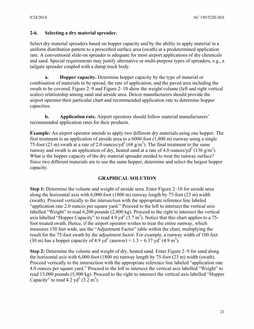
Step 1: Determine the volume and weight of airside urea. Enter Figure 2–10 for airside urea along the horizontal axis with 6,000-foot (1800 m) runway length by 75-foot (23 m) width (swath). Proceed vertically to the intersection with the appropriate reference line labeled “application rate 2.0 ounces per square yard.” Proceed to the left to intersect the vertical axis labelled “Weight” to read 6,200 pounds (2,800 kg). Proceed to the right to intersect the vertical axis labelled “Hopper Capacity” to read 4.9 yd3 (3.7 m3). Notice that this chart applies to a 75-foot treated swath. Hence, if the airport operator wishes to treat the entire runway, which measures 150 feet wide, use the “Adjustment Factor” table within the chart, multiplying the result for the 75-foot swath by the adjustment factor. For example, a runway width of 100 feet (30 m) has a hopper capacity of 4.9 yd3 (answer) × 1.3 = 6.37 yd3 (4.9 m3).
Step 2: Determine the volume and weight of dry, heated sand. Enter Figure 2–9 for sand along the horizontal axis with 6,000-foot (1800 m) runway length by 75-foot (23 m) width (swath). Proceed vertically to the intersection with the appropriate reference line labeled “application rate 4.0 ounces per square yard.” Proceed to the left to intersect the vertical axis labelled “Weight” to read 13,000 pounds (5,900 kg). Proceed to the right to intersect the vertical axis labelled “Hopper Capacity” to read 4.2 yd3 (3.2 m3).
21

AC 150/5220-20A 9/24/2014
Table 2-5. Weight to volume relationship of sand and urea
Weight/Volume Relationship of Sand and Urea
Weight of Material Volume of Material Sand 13,000 lbs. (5,900 kg)
heaviest 4.2 yd3 (3.2 m3)
Airside Urea 6,200 lbs. (2,800 kg) 4.9 yd3 (3.7 m3) largest
Selection: Select a hopper capacity of at least 5.0 cubic yards to accommodate the largest volume namely, airside urea, see Table 2-5. With this information, the airport operator can contact spreader manufacturers for acceptable types and sizes. Note: In selecting the size of a spreader unit, the location of the dry material storage bins/silos and the time it takes to reload the hopper(s) with material must also be considered.
Upon determining the largest hopper capacity and heaviest weight of material being spread, see Chapter 5 for selection of models and the recommended SAE ARP equipment specification for purchasing, testing, and certifying dry material spreaders.
22

9/24/2014 AC 150/5220-20A
Figure 2–9. Hopper capacity – sand
23

AC 150/5220-20A 9/24/2014
Figure 2–10. Hopper capacity – urea
24

9/24/2014 AC 150/5220-20A
2-7. Selecting a liquid material spreader.
Select liquid material spreaders based on tankage capacity and by the ability to apply material in a uniform distribution pattern to a prescribed surface area (swath) at a predetermined application rate. In contrast to dry sand, application rates of de/anti-icer fluids vary depending on ice and snow accumulations and overall weather conditions. According to AC 150/5200-30, application rates for a specific product are based on manufacturer recommendations. For example, rates are typically 0.30 gal/1,000 ft2 (12.2 liter/1,000 m2) when anti-icing or 1.0 gal/1,000 ft2 (41 liter/ 1,000 m2) when deicing. In all cases, refer to the manufacturer’s recommended application rates for anti-icing and deicing applications. The size of the sprayer tank is a function of the square footage to be covered and the maximum fluid coverage rate to be applied.
Example: Determine the tankage capacity. The airport operator determines that 700,000 ft2 (65,000 m2) of Priority 1 paved area will receive a liquid deicer applied at the manufacturer’s recommendation of 1.0 gal/1,000 ft2 (41 liter/1,000 m2). This operation will meet all but the most severe conditions with only one pass of the equipment.
NUMERICAL SOLUTION
Step 1: Determine the total gallons of liquid deicer used.
Multiple as follows: 700,000 ft2 × 1.0 gal/1,000 ft2 = 700 gals (65,030 m2 × 41 liter/1,000 m2 = 2,650 liters)
Selection: Select at least a tank capacity of 700 gallons. Note: When selecting the size of a liquid spreader unit, consider the location of the storage tanks and the time it takes to reload the sprayer with fluid.
Upon determining the tank capacity, see Chapter 5 for selection of models and the AC specification for purchasing, testing, and certifying liquid material spreaders.
2-8. Selecting a runway broom with airblast.
The selection process follows the process described per SAE ARP 5564, Runway brooms, paragraph 6, in particular paragraph 6.1 and Appendix A of the SAE ARP specification.
25

AC 150/5220-20A 9/24/2014
This page intentionally left blank
26

9/24/2014 AC 150/5220-20A
Chapter 3. High-Speed Rotary Plows
3-1. Description.
High-speed rotary plows, also called “rotaries” or “snowblowers,” are primarily used to cast heavy concentrations of snow away from movement areas such as runways and taxiways. The equipment, which may be self-propelled or attached to a carrier vehicle, uses one or more rotating elements (single or two-stage units) to disaggregate a snowpack. The disaggregated snow is then broken into particles small enough to pass through a casting mechanism and directional chute. Because of their large capacity, self-propelled rotary plows are frequently required at medium to large airports while rotary plows attached to a carrier vehicle may be more appropriate at smaller facilities or facilities where the climate is less severe.
a. Single-stage high-speed rotary plows. Single-stage high-speed rotary plows use one rotating device to accomplish both the disaggregating and the casting functions. Single-stage rotary plows may be of any suitable design with either single or dual turbine fans and with or without moveable or fixed side extension wings. Two common designs are the scoop wheel type (see Figure 3–1), which may have a propeller-like pre-cutter bar to break up hard snow, and the drum with turbine impeller type (Figure 3–3g).
b. Two-stage high-speed rotary plows. Two-stage high-speed rotary plows separate the disaggregating function from the casting function (see Figure 3–1 and Figure 3–2). Disaggregators can be of any suitable design, such as a solid auger (single or dual) or ribbon reel (helical). Impellers, which cast the snow, can be of web or disk design.
c. Options. In selecting a high-speed rotary plow design (single-stage or two-stage) to meet the demands of local conditions, an airport operator should consider the various equipment options available and acquire the most effective unit.
3-2. High-speed rotary plow capacities.
Table 2-3 shows snow removal capacities and casting distances for various high speed rotary plow classes. Acquire these in either single or two-stage design. Their capacities are in tons/hour. Measure the casting distance from the longitudinal centerline of the snow removal unit to the center of mass within the perimeter of the cast pattern. Conduct the test when there is no wind.
3-3. SAE ARP equipment specification for high-speed rotary plows.
High-speed rotary plows and carrier vehicles must be in accordance with SAE ARP 5539, Rotary Plow with Carrier Vehicle. An additional federal AIP/PFC specification requirements for SAE ARP 5539 is that for carrier vehicle controllability and safety, all-wheel drive must be standard.
27

AC 150/5220-20A 9/24/2014
Figure 3–1. Single-stage rotary plow
Figure 3–2. Two-stage rotary plow
28

9/24/2014 AC 150/5220-20A
Figure 3–3. Typical rotary plow types
29

AC 150/5220-20A 9/24/2014
This page intentionally left blank.
30

9/24/2014 AC 150/5220-20A
Chapter 4. Snow Plows
4-1. Description.
Snow plows consist of a cutting edge to shear snow from the pavement and a moldboard to lift and cast the dislodged snow to the side of the cleared path. The cutting edge may ride in contact with the pavement or be held a small distance above it by means of shoes or caster wheels. A complete snow plow unit consists of a snow plow, carrier vehicle, and accessories (see Figure 4–1). Snow plow sizes may be classified as follows:
a. Small snow plow. This category includes snow plows with cutting edge lengths ranging from approximately 6 feet up to 10 feet (1.8 m up to 3.0 m). Included in this category are underbody-mounted truck scrapers with similar length cutting edges.
b. Intermediate snow plow. This category includes snow plows with cutting edge lengths ranging from approximately 10 feet up to 15 feet (3.0 m up to 4.6 m). Included in this category are underbody-mounted truck scrapers with similar length cutting edges.
c. Large snow plow. This category includes snow plows with cutting edge lengths ranging from approximately 15 feet up to 22 feet (4.6 m up to 6.7 m). Included in this category are ramp dozer plows and large special purpose plows.
d. Extra large snow plow. This category includes plows with cutting edge lengths greater than 22 feet (6.7 m). Included in this category are ramp dozer plows and extra-large special purpose plows.
4-2. Snow plow uses.
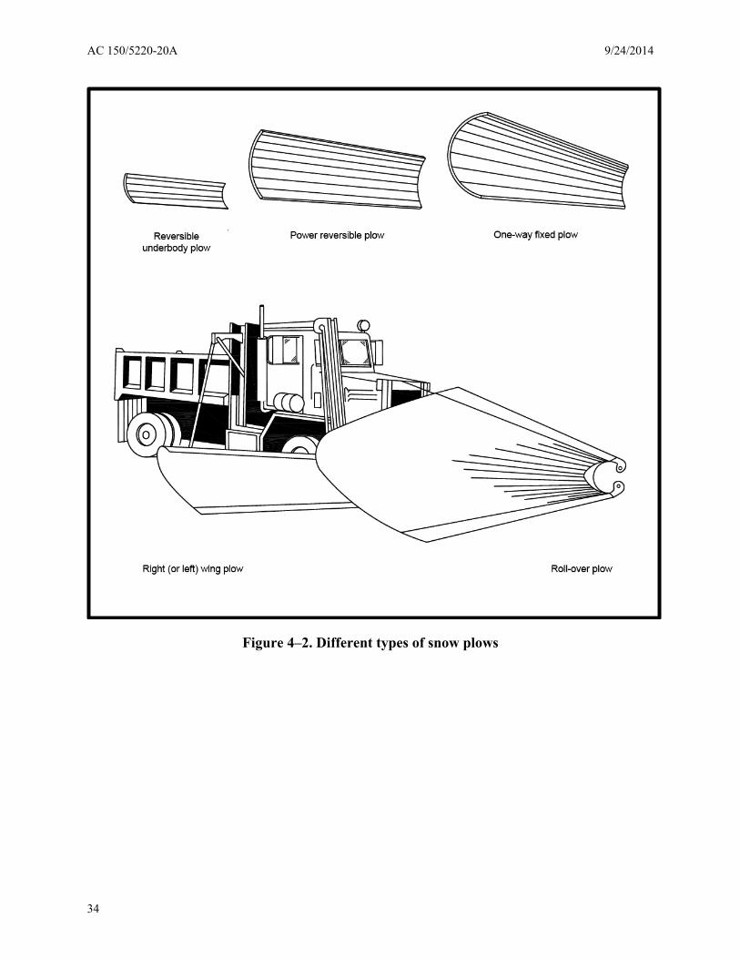
Snow plows are most commonly mounted on the front of a carrier vehicle, but they may also be mounted on the side or underneath the vehicle as illustrated in Figure 4–2. A flat and level moldboard deflector should be used when limiting the board casting of the plowed snow. A “bat wing” or large funnel design of the moldboard should be used when the intention is to broadcast the discharged snow over a greater distance and more spread out with less uniformity.
a. Front-mounted snow plows.
(1) One-way fixed angle snow plow. This unit is primarily used in large open area snowplowing operations that require a high-volume and high-speed snow discharge at fixed left or right cutting angles.
(2) Power reversible snow plow. This unit may be used for both large open area or confined area snowplowing operations. The design provides variable blade positions to either the right or left of the bulldozing position. This allows high volumes of snow to be displaced in a direction dictated by wind conditions or other constraints. The ability to reverse the snow plow angle improves operational efficiency and may reduce the number of snow plow units required.
31

AC 150/5220-20A 9/24/2014
(3) Rollover power reversible snow plow. The primary use of this unit is for large open area snowplowing operations. High-speed and high volume snow discharge to either a right or left cutting angle may be achieved by rotating the blade assembly through 180 degrees. This type of snow plow is not recommended for bulldozing. The rollover concept reduces snow spillage by confining and spreading it through a tapered moldboard design.
(4) Power reversible snow plow with folding wings. The primary use of this unit is for wide and extra-wide swath snowplowing operations at various speeds. Cutting an extra-wide swath may require a special carrier vehicle having high horsepower. Make sure that the wings fold snugly against the carrier vehicle chassis when not in use.
(5) Flexible reversible snow plow. This unit is made of polymer construction and is capable of changing its cross-sectional shape. It is versatile and can be used as a one-way fixed angle snow plow or a power reversible snow plow with the added feature that it can be adjusted to fit a variety of weather and snow conditions.
(6) Ramp dozer. The primary use of this unit is in confined areas that require wide to extra-wide swath plowing, but it may also be used to transport and dump snow. The ramp blade is equipped with side plates to contain snow and prevent spillage. Removal of the moldboard cutting edge allows the moldboard to act as a bucket for snow loading.
(7) Snow buckets and snow baskets. Such equipment must be equipped for mounting on a wheel loader or industrial 4×4 tractor. See Part B of Appendix 4 for details.
b. Side-mounted wings.
(1) Extension wings. Mount these attachments on either side of the carrier vehicle to increase the swath of the front-mounted snow plow. They are capable of high volume, high-speed snow removal operations.
(2) Leveling wings. These units operate with a front-mounted snow plow for windrow and snow bank leveling/trimming operations. The adjustable height of the leveling wing is designed to cast high drifted snow banks away from the cleared snow swath cut by the snow plow. They are designed for high-speed snow removal operations.
c. Underbody-mounted scraper. Mount this unit behind the cab and on the underbody of a large truck or grader. During operation, the scraper blade applies constant ground pressure on the pavement surface. The blade is capable of rotating its snow cast to either the left or right, thereby enhancing its ability to operate in confined areas.
4-3. SAE ARP equipment specification for snow plows and carrier vehicles.
Snow plows and carrier vehicles must be in accordance with SAE ARP 5943, Snowplows and Hitches.
32

9/24/2014 AC 150/5220-20A
Additional federal AIP/PFC specification requirements for SAE ARP 5943 follow:
a. For conventional carrier vehicle controllability and safety, all-wheel drive must be provided.
b. Only non-metal cutting edges may be used on pavements having in-pavement lighting.
c. Under paragraph 4.1.1.(c), the snow plow manufacturer must provide the airport sponsor certification for the polyethylene moldboard material.
d. Under paragraph 4.2.1, the overall width of the snow plow assembly in the folder position (wings retracted) with required casters must allow enter into the federally funded snow removal building (AC 150/5220-18, Buildings for Storage and Maintenance of Airport Snow and Ice Control Equipment and Materials) housing the snow plow and other such equipment.
Note: This figure illustrates a power reversible snow plow with all typical components. Details of snow
plow components may vary with snow plow manufacturer and type of snow plow.
Figure 4–1. Snow plow components
33
AC 150/5220-20A 9/24/2014
Figure 4–2. Different types of snow plows
34

9/24/2014 AC 150/5220-20A
Chapter 5. Material Spreaders
5-1. Description.
The function of a material spreader is to provide a continuous, unrestricted, accurately metered flow of sand and solid or liquid deicers/anti-icers per AC 150/5200-30 to a pavement surface over a predetermined spread area. Spreader units may be a permanently vehicle-mounted, a slip-in hopper, or they may be towed by a carrier vehicle. A spreader unit consists of a material storage compartment (hopper or tank), pre-wetting mechanism, a feed mechanism to carry the material to the discharge opening, a metering device to control the application rate, and a distribution mechanism. The selection of a material spreader is primarily defined by the carrying capacity of the hopper (cubic yards) or tankage (gallons) and the width of the path to receive material. This chapter provides a method to determine hopper and tankage capacities.
5-2. Types of material spreaders.
a. Dry material spreaders. This type of material spreader for sand and solid de/anti-icers uses a hopper type material spreader combined, as standard, with a liquid reservoir for pre-wetting sand with an approved liquid de/anti-icer, for skid mounting or chassis mounting onto a carrier vehicle. Figures 5-1 and 5-2 illustrate typical types of dry material spreaders. Spreading width varies from about 12 feet (3.6 m) to about 80 feet (24 m) and hopper capacity varies from about 5 yd3 (4 m3) to 16 yd3 (12 m3)
(1) Conventional hopper spreaders. Chassis mounted or slip in type hopper spreaders mount longitudinally between or directly over the carrier vehicle frame members.
(2) Multi-purpose dump body spreader. Multi-purpose dump body spreaders mount directly over the carrier vehicle frame members. The spreader may function as an elevating-dump body and as a material spreader.
(3) Tailgate spreader. Tailgate spreaders mount on or under the tailgate of an elevating dump body. Hopper capacity is determined by the capacity of the dump body.
(4) Towed trailer spreader. A trailer spreader is towed by a separate vehicle but has its own frame and suspension system.
b. Liquid material spreaders. Liquid material spreaders may be self-contained or mounted on a carrier vehicle. These spreaders apply de/anti-icing chemicals to pavement surfaces via a spray applicator system consisting of a supply tank, pump, flow rate monitor, and a spray bar equipped with nozzles. Tank capacities typically range from 500 to 5,000 gallons (1,900 to 19,000 liters). Justify the tank size requirement based upon the Priority 1 pavement area declared and the application of 0.5 gallon of liquid deicer/anti-icing fluid per 1,000 square feet (20.4 liters/1,000 m2) within 30 minutes for airports with greater than 40,000 operations or within 1 hour for airports with less than 40,000 operations.
35

AC 150/5220-20A 9/24/2014
5-3. SAE ARP equipment specification for material spreaders.
Sand and solid deicing/anti-icing material spreaders must be in accordance with SAE ARP 6059, Solid Deicing/Anti-icing Material Spreader for Airport Application. SAE G15 is developing draft ARP 5559, Liquid Deicing/Anti-icing Material Spreader for Airport Application. This AC will reference that aerospace recommended practice upon its issuance by SAE. Until then, liquid deicing/anti-icing material spreaders must be in accordance with Appendix 5 Part B specifications for liquid spreaders. Additional Federal AIP/PFC specification requirements for SAE ARP 6059 follow:
a. For conventional carrier vehicle controllability and safety, all-wheel drive must be provided.
b. Paragraph 3.2 specifies the maximum material spreading width of not less than 40 feet.
c. Paragraph 3.3.1; for new carrier vehicle applications the spreader manufacturer and the airport operator must work with the carrier vehicle manufacturer to ensure compatibility.
d. Paragraph 3.9; type 1 standard; type 2 not eligible.
e. Paragraph 3.16; the following items are standard:
(1) Paragraph 3.16.4; one per airport under SAE ARP 5623, Mobile Infrared Runway Surface and Digital Ambient Sensor.
(2) Paragraphs 3.16.9, 3.16.10; 3.16.11; 3.16.12; 3.16.15; 3.16.16; 3.16.17; and 3.16.18 are all standard.
f. Paragraph 3.17 not eligible.
g. Paragraph 3.18; only 1 set of manuals, diagnostic tools, equipment, software, and programs are furnished.
36

9/24/2014 AC 150/5220-20A
Figure 5–1. Dry material spreader types
37

AC 150/5220-20A 9/24/2014
Note: This figure depicts the typical layout of a typical dry hopper system having a hydraulic or
mechanical drive, a belt or chain-type conveyor, and a dual spinner spreader. Some optional recommended devices are also depicted. Other spreader configurations may contain components differing in design, but essentially perform the same function.
Figure 5–2. Example of one design and component layout of a dry material spreader
38

9/24/2014 AC 150/5220-20A
Chapter 6. Runway Brooms
6-1. Description.
Runway brooms with airblast are primarily used in the high-speed sweeping and cleaning of snow, slush, ice, and debris from movement and non-movement areas by using a brush. They incorporate high-speed brooms that consist of a number of brush sections, which may be front mounted to a carrier vehicle (conventional or dedicated), mounted underbody, or mounted on a trailer arrangement that is towed by a carrier vehicle. All are capable of sweeping wet slushy snow as well as fine dry snow from pavement surfaces. The broom framework design provides continuous service under difficult working conditions in cold climates. Complement a broom with an airblast system located behind the brush assembly. Use the runway brooms with airblast systems to sweep the pavement area clean of snow, slush, sand, and other debris, help dry the pavement surface, and clear snow from around runway lights.
6-2. Types of runway brooms.
a. Typical configurations of runway brooms being used worldwide on airports are as follows. The front mounted configuration has the broom preceding the carrier vehicle and allows the operator to directly observe the area being swept. Two other similar versions are a tractor mounted and a loader mounted configuration with the broom attached to the front. The loader mounted option requires a dedicated auxiliary engine. The towed behind configuration fixes the broom to a trailer that is towed by a carrier vehicle. The operator uses mirrors to observe the area being swept and must maneuver the carrier vehicle and trailer together by carefully observing their outer dimensions. The underbody configuration places the broom between the front and rear axles of the carrier vehicle.
b. Figures 6-1 and 6-2 illustrate some of the broom types that use a conventional carrier vehicle configuration while SAE ARP 5548, Multi-Tasking Equipment (MTE) for Airfield Snow Removal, illustrates the various MTE dedicated carrier vehicle configurations. Figure 6-3 illustrates common types of broom bristles.
6-3. Classification.
The following two general classes constitute the family of runway brooms. Measure all swath widths when the broom is angled 30 degrees from the transverse position.
a. Small swath sweeper. This sweeper class may be of any physical design having a demonstrated or manufacturer’s certified snow or slush removal and broadcasting ability sufficient to produce clear pavement within the swath width at the rated speed. The sweeper must have a minimum broom diameter of 36 inches (91 cm) and a swath width of not more than 12 feet (3.7 m).
b. Large swath sweeper. This sweeper class may be of any physical design having a demonstrated or manufacturer’s certified snow or slush removal and broadcasting ability sufficient to produce clear pavement within the swath width at the rated speed. The sweeper must
39

AC 150/5220-20A 9/24/2014
have a minimum broom diameter of 36 inches (91 cm) and a swath width greater than 12 feet (3.7 m).
6-4. SAE ARP equipment specification for runway brooms with airblast.
Runway brooms with airblast must be in accordance with SAE ARP 5564, Airport Runway Brooms. Additional federal AIP/PFC specification requirements for SAE ARP 5564 follow:
a. For conventional carrier vehicle controllability and safety, all-wheel drive must be provided for conventional carrier vehicles.
b. For dedicated carrier vehicle (MTE) controllability and safety, all-wheel drive must be provided for MTE carrier vehicles.
c. Airblast is standard equipment for all selections.
d. Under paragraph 6.22 of SAE ARP 5564, the following additional equipment is standard. Other items listed under paragraph 6.22 are not eligible.
(1) Specialized tools – not to include computers and electronic diagnostic machines.
(2) Cold weather package – must provide justification for approval.
(3) Optional brush wafers and cassettes – only wafers permitted.
(4) LED marker lights located per SAE ARP 5564.
(5) An automatic lubrication system for all possible points.
(6) 20-pound fire extinguisher.
(7) Brush speed control by ground control.
(8) Foreign object debris (FOD)/debris pickup box with cab controls.
40

9/24/2014 AC 150/5220-20A
Figure 6–1. Typical runway brooms
41

AC 150/5220-20A 9/24/2014
Note: Typical layout showing common sweeper components and construction features for most sweeper
types, pushed as well as towed.
Figure 6–2. Towed type runway broom
42

9/24/2014 AC 150/5220-20A
Figure 6–3. Common types of broom bristles used on airports
43

AC 150/5220-20A 9/24/2014
This page intentionally left blank.
44

9/24/2014 AC 150/5220-20A
Chapter 7. Types of Carrier Vehicles
7-1. Description.
The term carrier vehicle represents the various self-propelled prime movers that provide the power necessary for the snow removal and ice control equipment to move snow, slush, ice, and other debris from the pavement during winter operations. Carrier vehicle selection is determined by the mission(s) to be performed and the capacity of the selected equipment to perform the designated task(s). The term “capacity” can refer to the amount of snow to be removed, the hopper of dry material spreaders, or tankage of liquid material spreaders.
a. Truck type conventional carrier vehicles. Truck type conventional carrier vehicles are standard production truck models designed primarily to meet an airport’s snow and ice control needs by attaching or/and towing snow removal and ice control equipment. Additionally, this truck type can be of an integrated design that is built for a specific piece of equipment, such as a self-propelled high-speed rotary plow. Conventional carrier vehicles also have the ability to perform secondary airport functions; they can be equipped for several summer time tasks, such as Foreign Object Debris (FOD) exercises. They should conform to the manufacturer’s performance recommendations and be suitable for mounting all specified accessories.
b. Truck type special purpose carrier vehicles. Special purpose carrier vehicles can be conventional or dedicated carrier vehicles. An example of a conventional special purpose carrier vehicle is one that is customized specifically to meet special airport needs. Some examples include a specialized high-speed rotary plow necessary to remove and cast huge volumes of heavy dense snow; a specialized snow plow that requires an extra-wide moldboard and horsepower to perform extra-wide swath clearing operations over long distances. In comparison, this AC makes a distinction to identify those multi-task carrier vehicles exclusively built with the capability to perform three integrated functions, namely snowplowing, brooming, and airblasting at a speed of at least 30 mph (48 km/h). Industry refers to this specifically built carrier vehicle as high-speed multi-task equipment (MTE) as defined by SAE ARP 5548, Multi-Tasking Equipment (MTE) for Airfield Snow Removal High Speed, Multi-Tasking Snow Removal Unit to include Carrier Vehicle, Snow Plow, Rotary Broom High Velocity Air. For airport operators selecting MTEs, see paragraph 7-4 for further information and requirements.
c. Front-wheel loaders. Front-wheel loaders are standard production four-wheel drive articulated and non-articulated conventional carrier vehicles, normally equipped with a front-mounted bucket or basket, that operate at low speeds of 5 to 20 mph (8 to 30 km/h). They are very efficient for short haul operations and are used to clear or haul compacted snow and ice from ramp and terminal areas and around pavement lights. A front-wheel loader will generally out-perform a truck-mounted snow plow in such confined areas, but it is not as efficient when large open paved areas need to be cleared quickly. Other applications include snow loading and stockpiling and loading of solid chemicals and airside sand.
45

AC 150/5220-20A 9/24/2014
d. Industrial 4×4 tractors. Industrial 4×4 tractors are standard production models adapted for snow and ice control work in confined areas. While similar to wheel loaders, most are built to operate at higher speeds.
7-2. Carrier vehicle dimensions.
Carrier vehicle dimensions should permit the carrier vehicles to pass through the standard door openings of service and storage buildings. See AC 150/5220-18, Buildings for Storage and Maintenance of Airport Snow and Ice Control Equipment and Materials, for FAA recommended door openings, parking space set-asides, and other clearances within these buildings. Additionally, the selected dimensions should permit servicing of equipment by standard lifts and cranes without the need for special equipment or the need for building modifications.
7-3. Outdoor storage of carrier vehicles.
See Appendix 2 for additional equipment to consider when operating a carrier vehicle below -40°F (-40°C) or when the carrier vehicle must be stored outside or in an unheated building.
7-4. SAE ARP equipment specification for MTE dedicated carrier vehicles.
MTEs must be in accordance with SAE ARP 5548, Multi-Tasking Equipment (MTE) for Airfield Snow Removal High Speed, Multi-Tasking Snow Removal Unit to include Carrier Vehicle, Snow Plow, Rotary Broom High Velocity Air. Additional Federal AIP/PFC specification requirements for SAE ARP 5548 follow:
a. An airport sponsor requesting a MTE must be eligible for both a snow plow truck and a runway broom. One MTE replaces the eligibility for two pieces of snow removal and ice control equipment.
b. Complete a Snow and Ice Control Plan and calculate the tons per hour requirement of the Priority 1 paved area for the MTE performance.
c. For dedicated carrier vehicle (MTE) controllability and safety, power must be provided to at least two axles.
d. For dedicated carrier vehicle other than MTE controllability and safety, all-wheel drive must be provided.
e. Additional features not a part of this specification may not be eligible for federal funding.
f. This SAE ARP specification allows the procurement official to specify various options or selections; however, unless a selection is offered in Table 7-1 the purchaser will receive the standard catalog equipment offered on the winning bidder’s equipment. A selection is not available to the procurement official.
46

9/24/2014 AC 150/5220-20A
Table 7-1. MTE specification selections
SAE ARP 5548
Paragraph number
Selection Descriptions
Pre-approved by FAA as standard,
required item
Type of Airport
Selection See Notes 1
and 2 5.1 Indicate acceptable design(s):
1. Modular unit 2. Integral non-articulating 3. Integral articulating
Justification required
Note 2
5.3.1 100-foot wall to wall maximum turning test YES Note 1 Supplemental performance testing Airport may
select and manufacturer should attend testing
6.2.3 Install pintle hitch YES Note 1 6.3 Standard catalog diesel engines
Note: Alternative fuel engines (not available at this time.)
YES Note 1
6.3.7 Thermostatically controlled fuel tank heaters
Justification required
Note 2
6.3.7 Thermostatically controlled fuel line heaters Justification required
Note 2
6.4.4i Transfer case (standard manufacturer’s equipment)
YES Note 1
6.6.1 Steering enhancements (standard manufacturer’s design)
YES Note 1
6.6.2 Standard catalog steering YES No selection among stated options
6.6.2 Enhanced steering Justification required
Note 2
6.6.2 AWS managers switch Justification required
Note 2
6.8.3 Spare rim/tire Justification required
Note 2
6.9.2 Arctic type hoses Justification required
Note 2
6.9.2 UV protected hoses Justification required
Note 2
6.9.4 Hydraulic system preheater (must be justified)
Justification required
Note 2
47

AC 150/5220-20A 9/24/2014
SAE ARP 5548
Paragraph number
Selection Descriptions
Pre-approved by FAA as standard,
required item
Type of Airport
Selection See Notes 1
and 2 6.10.2 Auto-lubrication system Justification
required Note 2
6.11.1 Managed battery system YES Note 1 6.12d Choose 1 type: YES Note 1
(a) Reflectors (b) Conspicuity markings
6.12.4 Auxiliary or specialty lighting NO Not allowed 6.12.6 Audible back up alarm YES Note 1 6.12.7 Standard equipment horn (manufacturer’s
standard air or electric - no choice) YES Note 1
6.13.1 Engine coolant heater YES Note 1 6.13.2 Engine oil heater Justification
required Note 2
6.13.4 Ether start provision YES Note 1 6.13.6 Hydraulic tank heaters Justification
required Note 2
6.15 Operator’s cab (no choice of cab, manufacturer’s standard design)
YES Note 1
6.15.3 Cab glass (no choice of cab, manufacturer’s standard design)
YES Note 1
6.15.4 Heated wipers & fluid system Justification required
Note 2
6.15.7 Rear view mirrors (No choice of mirrors, manufacturer’s standard design)
YES Note 1
6.15.8 Sun visors (No choice of visors, manufacturer’s standard design)
YES Note 1
6.15.11 Prewired for two-way radio components (power only)
YES Note 1
6.15.12 Windshield deluge system YES Note 1 6.16.7 AM/FM radio with clock NO Not allowed 8.5 Select (1) type of cutting edge:
YES Note 1
(a) Tungsten carbide Not allowed with in-pavement lighting
(b) Rubber (must have in-pavement lights) (c) Polyurethane (must have in-pavement lights)
48
9/24/2014 AC 150/5220-20A
SAE ARP 5548
Paragraph number
Selection Descriptions
Pre-approved by FAA as standard,
required item
Type of Airport
Selection See Notes 1
and 2 (d) High carbon steel Not allowed with
in-pavement lighting
(e) Rubber section blades w/carbide inserts (f) Reverse angle style cutting edge
8.6 Single or double acting lift cylinder (manufacturers standard design)
YES Note 1
8.6.1 Plow quick hitch Justification required
Note 2
8.7 Spray guard YES Note 1 8.8 Shock/impact absorbers YES Note 1 8.10 Select 1 type:
(a) Single caster wheel assembly (manufacturers standard design) (b) Dual caster wheel assembly (manufacturers standard design)
YES Note 1
8.10.1 & 2 Type of caster assembly – no selection (manufacturers standard design)
YES Note 1
9.1 Stowable broom head (must be justified) Justification required
Note 2
9.1 Non-stowable broom head YES Note 1 9.2.3 36 inch brush diameter Justification
required Note 2
9.2.3 46 inch brush diameter (recommended) Justification required
Note 2
9.2.4 Select 1 type: YES Note 1 (a) Wire bristles (b) Poly bristles (c) Poly/wire combo: Mix: _____ (Sponsor must specify mix.)
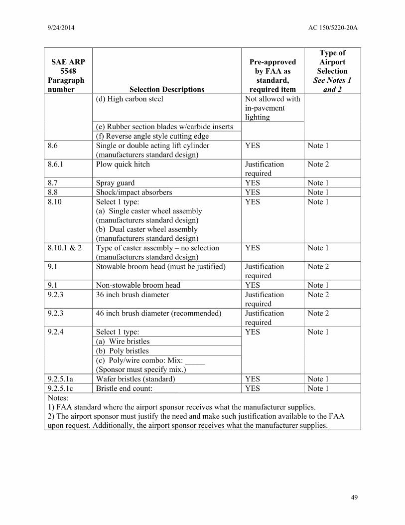
9.2.5.1a Wafer bristles (standard) YES Note 1 9.2.5.1c Bristle end count: ______ YES Note 1 Notes: 1) FAA standard where the airport sponsor receives what the manufacturer supplies. 2) The airport sponsor must justify the need and make such justification available to the FAA upon request. Additionally, the airport sponsor receives what the manufacturer supplies.
49

AC 150/5220-20A 9/24/2014
This page intentionally left blank.
50

9/24/2014 AC 150/5220-20A
Chapter 8. Operational Standards and Compliance Testing
8-1. General.
The manufacturer is responsible for conducting tests to ensure that its snow removal and ice control equipment meets the operational and performance requirements it advertises. The manufacturer must submit certified records of these compliance tests with each response to an invitation to bid. Equipment tests must be conducted on standard production models and not on specially constructed prototypes.
a. Pre-testing. Examine each test carrier vehicle to ensure that it is a standard production model and not a specially constructed unit made specifically for the test. Prior to testing, all controls, adjusting mechanisms, hydraulic systems and other assemblies must be operated to ensure against leaks, restrictions, and malfunctions. Once assured that the unit is fit, actual testing may begin.
b. Additional testing. The purchaser may consider conducting his or her own operational performance tests on equipment prior to acceptance. In such cases, the manufacturer should have the opportunity to witness the performance of such tests, but the costs for such testing and interpretation of results is the sole responsibility of the purchaser.
8-2. Required carrier vehicle tests.
Test the carrier vehicle in accordance with (1) this paragraph and (2) any referenced SAE ARP(s) for the specified equipment the carrier vehicle is to support. Conduct the following temperature, performance, and compliance tests when acquiring a carrier vehicle. Carrier vehicles must be all-wheel drive.
a. Cold weather operations. A fully-equipped carrier vehicle (all types) with all attached snow removal and ice control equipment should be able to perform normal operations at an ambient temperature:
(1) of 10°F (-12°C) below the lowest temperature in which the vehicle is expected to operate, or
(2) at -40°F (-40°C) at airports located in extremely cold climates.
b. Hot weather operations. The vehicle should be capable of operating at an ambient temperature of 70°F (21°C) at the maximum speed recommended by the manufacturer without any of the vehicle components exceeding their normal operating temperature.
c. Power. Carrier vehicles must have sufficient power to perform all operational and attachment functions simultaneously.
d. Performance. The following tests must be conducted on a carrier vehicle loaded to its Gross Vehicle Weight and must include the following systems: hydraulic, power train, brake, lighting, controls, and instruments.
51

AC 150/5220-20A 9/24/2014
(1) 10 mile test. Drive the carrier vehicle over hard surfaced roads at normal airport speeds for a distance of 10 miles (16 km) with no problems experienced. Focus special attention on vibration, steering, vehicle drift, rattles, leaks, and interior controls.
(2) One hour test. Perform this time test at a speed of 5 mph (8 km/h) over all types of terrain that would normally be encountered at the airport.
(3) Service brake test. Conduct this test at speeds of 20 mph and 40 mph (32 km/h and 64 km/h). Using the service brakes only, the fully loaded carrier vehicle must be brought to a complete stop within a distance of 35 and 131 feet (11 and 40 m) respectively measured from the point of brake application. The test must be conducted for two complete cycles in either direction on a hard pavement surface that is dry, reasonably level and free of loose material. Make no steering corrections for vehicle drift during the stop.
(4) Emergency brake test. Conduct this test at a speed of 40 mph (64 km/h). Using the emergency brake only, the fully loaded carrier vehicle must be brought to a complete stop on the most critical airfield pavement grade within a distance of 288 feet (88 m) measured from the point of brake application. Conduct this test on a hard surface that is dry and free of loose material. Once stopped, the brake must continue to hold the carrier vehicle without movement for five minutes. Make no steering corrections for carrier vehicle drift during the stop.
8-3. High-speed rotary plow test.
Field test in accordance with SAE ARP 5539, Rotary Plow with Carrier Vehicle, for the casting distance and tonnage capacity specified by airport operator. Use Table 2-3 of this AC.
8-4. Snow plow test.
With the exception for 4×4 tractors and wheel loaders, field test to SAE ARP 5943, Snowplows and Hitches, to demonstrate the ability to:
a. sustain a speed of 25 mph (40 km/h) on level pavement with a snow plow cutting edge angle set at 37 degrees while negotiating a 3 to 6 inch (7.6 to 15.2 cm) snow accumulation having a density of approximately 25 lbs/ft3 (400 kg/m3) throughout a test section of at least 500 feet (150 m).
b. discharge snow to either side of the carrier vehicle while moving (if the unit is power reversible).
c. minimize snow spillover to 5 percent of total snow displaced.
d. produce a clear swath that is even, regular and non-skipping.
e. have the cutting edge (blade) free of vibration during operation.
f. carrier vehicles must be all-wheel drive.
52

9/24/2014 AC 150/5220-20A
8-5. Dry and liquid material spreader tests.
Field test in accordance with SAE ARP 6059. Liquid and dry spreader settings for swath width and application rate must be verified by field measurements to an accuracy of 2 percent under a no wind condition. Towed spreaders are not to vibrate excessively during operation and braking.
8-6. Runway brooms with airblast.
Field test in accordance with SAE ARP 5564, Airport Runway Brooms, and the following testing requirements:
a. A field test must be conducted to simulate operations on a runway or taxiway having a length of at least 1,000 feet (305 m). Snow depth may vary, but the broom should be capable of removing snow at the following depths and densities:
(1) Small Swath Brooms - 12 feet and under. Two inches (5 cm) of light snow having density of 8 to 15 lbs/ft3 (128 to 240 kg/m3) or one-half inch (1.3 cm) of slush at density of 40 lbs/ft3 (641 kg/m3).
(2) Large Swath Brooms - over 12 feet. Three inches (7.6 cm) of light snow having a density of 8 to 15 lbs/ft3 (128 to 240 kg/m3) or one inch (2.5cm) of slush at a density of 40 lbs/ft3 (641 kg/m3).
b. Speed must be as high as practical but not less than 8 mph (13 km/h) for small swath brooms and 25 mph (40 km/h) for large swath brooms.
c. The resulting cleared swath must demonstrate the following:
(1) The resulting swath width is reasonably clean without snow deposits resulting from bouncing or skipping of the brush.
(2) The unit with airblast must be capable of varying its brush rotational speed, angle of attack, and the degree of brush pressure applied to a surface area.
(3) The unit with airblast must be capable of broadcasting snow to either side of the carrier vehicle.
(4) The broom should show no performance degradation when sweeping thin deposits of sand, ash, water, or other light debris.
(5) The unit with airblast must be designed to allow all performance and monitoring functions to be controlled or observed by a single operator from the carrier vehicle cab.
53

AC 150/5220-20A 9/24/2014
This page intentionally left blank.
54
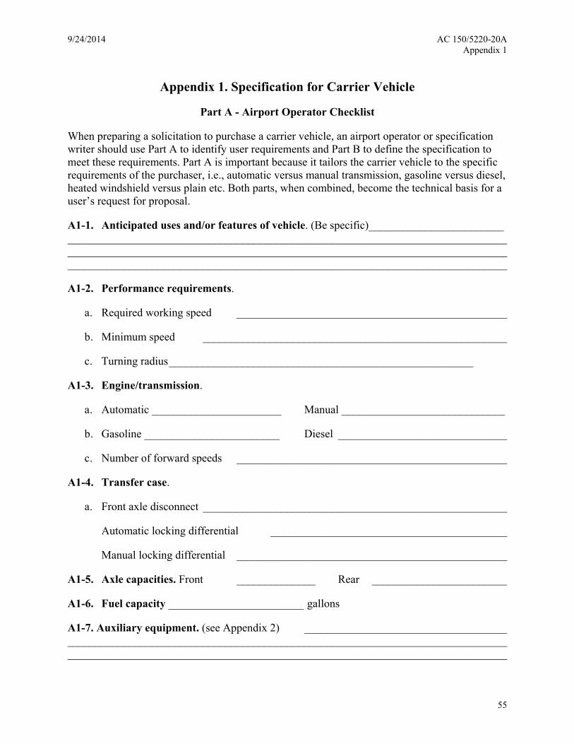
9/24/2014 AC 150/5220-20A Appendix 1
Appendix 1. Specification for Carrier Vehicle
Part A - Airport Operator Checklist
When preparing a solicitation to purchase a carrier vehicle, an airport operator or specification writer should use Part A to identify user requirements and Part B to define the specification to meet these requirements. Part A is important because it tailors the carrier vehicle to the specific requirements of the purchaser, i.e., automatic versus manual transmission, gasoline versus diesel, heated windshield versus plain etc. Both parts, when combined, become the technical basis for a user’s request for proposal.
A1-1. Anticipated uses and/or features of vehicle. (Be specific)________________________ __________________________________________________________________________________________________________________________________________________________________________________________________________________________________________
A1-2. Performance requirements.
a. Required working speed ________________________________________________
b. Minimum speed ______________________________________________________
c. Turning radius ______________________________________________________
A1-3. Engine/transmission.
a. Automatic _______________________ Manual _____________________________
b. Gasoline ________________________ Diesel ______________________________
c. Number of forward speeds ________________________________________________
A1-4. Transfer case.
a. Front axle disconnect ______________________________________________________
Automatic locking differential __________________________________________
Manual locking differential ________________________________________________
A1-5. Axle capacities. Front ______________ Rear ________________________
A1-6. Fuel capacity ________________________ gallons
A1-7. Auxiliary equipment. (see Appendix 2) ____________________________________ ____________________________________________________________________________________________________________________________________________________________
55

AC 150/5220-20A 9/24/2014 Appendix 1
Part B - Specification for Carrier Vehicle
A1-8. Materials and components. See referenced SAE ARP equipment specification.
A1-9. Delivery.
a. Preparation for delivery.
(1) Shipment. The vendor is responsible for the safe and timely delivery of the vehicle and its accessories, spare parts, and tools to the agreed place of delivery.
(2) Marking. Carrier vehicles must be marked for shipment in accordance with instructions agreed to by the purchaser.
b. Instruction and training. The manufacturer must, at no additional cost, furnish the services of trained personnel to the purchaser at a time and place agreed to by all parties. These individuals must provide instruction to airport personnel sufficient for the personnel to familiarize themselves with the operation and maintenance of the carrier vehicle and its auxiliary equipment. The period of instruction must not be less than 24 hours or as specified in the referenced SAE ARP equipment specification.
56

9/24/2014 AC 150/5220-20A Appendix 2
Appendix 2. Optional/Alternate Equipment Specification
A2-1. General.
Most snow and ice control equipment is designed to operate under normal winter conditions. At various times, working tolerances and/or severe weather or operating conditions require specialized support equipment to assist the primary unit prior to or during operation. Several of these options are discussed below:
A2-2. Carrier vehicle.
Equipment to be considered when operating a carrier vehicle at or below -40°F (-40°C) or when the vehicle must be stored outside or in an unheated building is as follows:
a. Engine/transmission.
(1) Engine-jacket water heater. Recirculating type with thermostatic control and weatherproof receptacle plug (minimum - l500 watts).
(2) Engine oil pan heater. 300 watts
(3) Battery warmer pad. Approximately 50 - 100 watts per battery
(4) Transmission oil pan heater. Wattage as recommended by the transmission manufacturer
b. Vehicle cab.
(1) Additional door handles. Handles must be installed on lower part of vehicle cab door.
(2) Auxiliary cab heater and circulating fans.
(3) Mirrors.
(a) Remote control for exterior mirrors.
(b) Electrically heated exterior mirrors.
(4) Windows.
(a) Heated windshield.
(b) Extra window in lower part of cab doors.
(c) Reverse slope windshield.
(5) Seats. Heated driver seat.
57

AC 150/5220-20A 9/24/2014 Appendix 2
(6) Cab insulation upgrade (to reduce exterior noise below 85 dBa).
(7) Air horn.
c. Mechanical.
(1) Special starting systems.
(a) Dual battery system.
(b) Ether cold starting system.
(2) Permanently installed battery charger.
(a) Maintenance charging. (0-10 amp capacity)
(b) Automatic cutoff.
(c) Connection.
(i) Weather resistant and chassis mounted.
(ii) Adaptable to 110 volt electrical outlet
(iii) Heavy duty
(iv) 20 amp capacity
(3) Engine cooling.
(a) Oversize radiator.
(b) Radiator shutters. (if compatible with engine design)
(4) Automatic engine shutdown. An automatic engine shutdown system is equipped with an override switch to prevent engine damage due to low engine oil pressure, high coolant temperature, or low coolant level.
(5) Special alternator. Specify drive type, amperage, and voltage.
(6) All-wheel or articulated steering. For all-wheel steering systems, the rear drive-steer axle must be controlled in the cab.
(7) Silicone hoses.
d. Quick disconnect hitches.
(1) Automatic/remote hitch. Controls to activate the hitching and unhitching mechanisms must be located in the vehicle cab. The hitch must be capable of mating the plow
58

9/24/2014 AC 150/5220-20A Appendix 2
equipment to the carrier vehicle attachment points even when minor angular differences exist between the attachment points and the hitching assembly. An additional hydraulic, pneumatic, or mechanical locking/unlocking device may be installed to ensure safe and positive final coupling. Locking devices must be activated through the use of existing vehicle power systems.
(2) Semi-automatic hitch. The initial hook-up between carrier vehicle and hitching device must be controlled from the vehicle cab with final lock-on accomplished manually at the vehicle/ hitch interface. The hitch must be capable of initial hook-up even when minor angular differences exist between the plow attachment points and the hitching assembly. All manual locking devices must ensure a safe and positive final coupling.
A2-3. High-speed rotary plow.
a. Low temperature options.
(1) Engine-jacket water heater. (1,000 watt unit)
(2) Engine oil pan heater. (300 watt unit)
(3) Battery warmer pad. (500 watt unit)
b. Spot casting and loading chute.
A2-4. Snow plow.
a. Moldboard coatings. Polyurethane nonstick coatings when applied to the front face of a moldboard will reduce skin friction and prevent snow from sticking to the moldboard.
b. Snow deflector shield. A snow deflector shield may be attached to the upper edge of a snow plow moldboard. Attaching devices are hinges, bolts, and acceptable spring-loaded mechanisms.
A2-5. Material spreaders.
a. Dry material spreaders.
(1) Vehicle speed sensor system. This system must automatically regulate and match the material spread rate with vehicle speed. Operation of the system must be from the vehicle transmission or by auxiliary tire traction. The system must include an automatic material cut-off.
(2) Belt over chain. Attached to the standard conveyor chain, the belt provides a more positive delivery of product to spinner, resulting in a more uniform spreading pattern.
(3) Load choker. An inverted “V” type adjustable load choker will reduce the load pressure on the conveyor system of larger spreaders.
59

AC 150/5220-20A 9/24/2014 Appendix 2
(4) Cab shield. A shield projects from top of leading edge of the spreader over the truck cab. Its function is to protect against spillage of material on cab and drive train of carrier vehicle during loading.
(5) Chain oiler. An oiler operates by gravity flow and keeps the conveyor chain oiled during operation.
(6) Hopper cover. A cover runs the full length of the hopper and protects the load from the elements.
(7) Catwalks.
b. Liquid material spreaders.
(1) Calibration system. The calibration system must consist of a control console, a sensor control valve, a ground speed sensor, and an application rate sensor. It must maintain a uniform application rate at all normal carrier vehicle application speeds over the entire width of the boom or any combination of sections thereof.
(2) Flusher unit. A flusher unit must have four broad fan nozzles capable of delivering 150 gpm (567 liters/min) at 50 psi (345 kPa).
(3) Quick disconnect hitch. A quick disconnect hitch for a snow plow should be considered when purchasing a self-contained spreader unit.
60

9/24/2014 AC 150/5220-20A Appendix 3
Appendix 3. High-Speed Rotary Plow Specification
Part A - Airport Operator Checklist
When preparing a solicitation to purchase a rotary plow, an airport operator or specification writer should use Part A to identify user requirements and Part B to define the specification to meet these requirements. Part A is important because it tailors the high-speed rotary plow to the specific requirements of the purchaser, i.e., single-stage versus two-stage, solid auger versus turbine impeller, etc. Both parts, when combined, become the technical basis for the user’s request for bid proposal.
A3-1. Anticipated uses and/or features of high-speed rotary plow. (Be specific) __________________________________________________________________________________________________________________________________________________________________________________________________________________________________________
A3-2. Size of Priority 1 paved area ______________________ square feet (m2)
A3-3. Capacity ____________________ tons/hr
A3-4. Casting distance ________ ft(m) @ Snow weight (density) of _____ lbs/ft3(kg/m3)
A3-5. Anticipated speed of operation _______________________ mph (km/h)
A3-6. Unusual conditions/problems/obstructions (if any)
__________________________________________________________________________________________________________________________________________________________________________________________________________________________________________
A3-7. Other/optional equipment
__________________________________________________________________________________________________________________________________________________________________________________________________________________________________________
61

AC 150/5220-20A 9/24/2014 Appendix 3
Part B – High-Speed Rotary Plow Specification
A3-8. See paragraph 3.3 of this AC.
A3-9. High-speed rotary plows and carrier vehicles must be in accordance with SAE ARP 5539, Rotary Plow with Carrier Vehicle. Additional Federal AIP/PFC specification requirement for SAE ARP 5539 is that for carrier vehicle controllability and safety, all-wheel drive must be provided.
62

9/24/2014 AC 150/5220-20A Appendix 4
Appendix 4. Snow Plow Specification
Part A - Airport Operator Checklist
When preparing a solicitation to purchase a snow plow, an airport operator or specification writer should use Part A to identify user requirements, and Part B to define the specification to meet these requirements. Part A is important because it tailors the snow plow to the specific needs of the purchaser, i.e., type of plow desired, type of moldboard, plow shoes versus caster wheels, etc. Both parts, when combined, become the technical basis for a user’s request for bid proposal.
A4-1. Anticipated uses and/or features of snow plow. (Be specific) __________________ __________________________________________________________________________________________________________________________________________________________________________________________________________________________________________
A4-2. Size of Priority 1 paved area ______________________ square feet (m2)
A4-3. Type of plow preferred ________________________________________________ ______________________________________________________________________________
A4-4. Plow length ___________ ft (m), height __________ ft (m), width ___________ ft (m)
A4-5. Anticipated speed of operation _______________________ mph (km/h)
A4-6. Unusual conditions/problems/obstructions that may be encountered ____________ __________________________________________________________________________________________________________________________________________________________________________________________________________________________________________
A4-7. Typical snow conditions ________________________________________________ __________________________________________________________________________________________________________________________________________________________________________________________________________________________________________
A4-8. Moldboard _______________________ steel _________________________ non-steel
A4-9. Other/optional equipment ________________________________________________ __________________________________________________________________________________________________________________________________________________________________________________________________________________________________________
63

AC 150/5220-20A 9/24/2014 Appendix 4
Part B – Snow Plow Specification
A4-10. Snow plows and carrier vehicles must be in accordance with SAE ARP 5943, Snowplows and Hitches. See paragraph 2 below for snow baskets and snow buckets. Additional federal AIP/PFC specification requirements for SAE ARP 5943 follow:
a. For carrier vehicle controllability and safety, all-wheel drive must be standard.
b. Under paragraph 4.1.1.(c), the plow manufacturer must provide the airport sponsor certification for the polyethylene moldboard material.
c. Under paragraph 4.2.1, the overall width of the plow assembly in the folded position (wings retracted) with required casters must be allowed to enter the federally funded snow removal building (AC 150/5220-18, Buildings for Storage and Maintenance of Airport Snow and Ice Control Equipment and Materials) that houses the snow plow and other such equipment.
A4-11. Snow bucket.
a. Geometry. The capacity of a front-mounted bucket must range anywhere from 3 to 8 yd3 (2.4 to 6.2 m3) depending upon the type of snow removal operation.
b. Features. The bucket must be made of welded construction using high-strength, wear resistant steel plate and bracing. It must be equipped for mounting on a wheel loader or a 4×4 tractor. The installed bucket must be capable of sustaining a level load while being tilted 20° in the forward and transverse position. It must be equipped with a quick coupler hitch for swift changeovers. Snow buckets may have a built-up bottom of abrasion-resistant steel to improve wear life.
A4-12. Snow basket.
a. Geometry. The front-mounted basket width must range from 8 to 17 feet (2.4 to 5.2 m). The basket hitching assembly must be designed for easy mounting on a wheel loader or a 4×4 tractor.
b. Features. The basket must have the same pick up and discharge characteristics as a snow bucket, e.g., be capable of sustaining a level load while being tilted 20 degrees in the forward and transverse position. It must have a quick coupler hitch for swift changeovers. Baskets must be welded using flexible high-strength wear-resistant steel weaving over a steel frame. Construction must be of the minimum weight capable of withstanding the rigorous stress of loading and unloading. Snow baskets may have a built-up bottom of abrasion-resistant steel to improve wear life.
64

9/24/2014 AC 150/5220-20A Appendix 5
Appendix 5. Material Spreader Specification
Part A - Airport Operator Checklist
When preparing a solicitation to purchase a spreader system, an airport operator or specification writer should use Part A to identify user requirements and Part B to define the specification to meet these requirements. Part A is important because it tailors the spreader to the special preferences of the purchaser, i.e., special lighting, hopper/tank sizes, desired carrier vehicle cab features, special safety equipment, etc. Both parts, when combined, become the technical basis for a user’s request for bid proposal.
A5-1. Solid material spreader.
a. Anticipated uses and/or features of spreader. (Be specific) __________________ ____________________________________________________________________________________________________________________________________________________________
b. Size of Priority 1 paved area ____________________ square feet (m2)
c. Size of hopper __________________________ cubic yd (m3)
d. Material to be spread ________________________________________________
e. Application rate ____________________ ounces/yd2 (gr/m2)
f. Time needed to complete major operation _______________________ minutes
g. Proximity to loading farm _________________________________________ minutes
h. Capacity of loading farm ____________________________________ tons
i. Other __________________________________________________________________ __________________________________________________________________________________________________________________________________________________________________________________________________________________________________________
65

AC 150/5220-20A 9/24/2014 Appendix 5
A5-2. Liquid spreader
a. Anticipated uses and/or features of spreader. (Be specific) __________________ ____________________________________________________________________________________________________________________________________________________________
b. Size of Priority 1 paved area ____________________ square feet (m2)
c. Size of tank ____________________________ gal (liters)
d. Critical application rate ________________ ounces/1000 ft2 (liters/1000 m2)
e. Time needed to complete major operation _______________________ minutes
f. Proximity to loading farm _________________________________________ minutes
g. Capacity of loading farm ____________________________________ gallons(liters)
h. Other __________________________________________________________________ __________________________________________________________________________________________________________________________________________________________________________________________________________________________________________
66
9/24/2014 AC 150/5220-20A Appendix 5
Part B - Material Spreader Specifications
A5-3. Solid material spreader components
Sand and solid deicing/anti-icing material spreaders must be in accordance with SAE ARP 6059, Solid Deicing/Anti-icing Material Spreader for Airport Application.
A5-4. Liquid material spreader components
SAE G15 is finishing draft SAE ARP 5559, Liquid Deicing/Anti-icing Material Spreader for Airport Application. This AC will reference that aerospace recommended practice upon its issuance by SAE. Until then, the carrier vehicle for liquid spreaders complies with SAE ARP 6059 and the liquid spreader must comply with paragraph 2 below.
a. Standard equipment. A liquid material spreader must have the following standard equipment:
(1) Hydraulic system. The spreader hydraulic system must meet the basic requirements of the carrier vehicle system under SAE ARP 6059. The system must also be capable of supplying the power to operate the deicing pumps, to fold the booms, and to turn the spreader on and off.
(2) Tank. The tank must be constructed of grade 304 stainless steel or better. Optional construction, using polymer or fiberglass materials, is acceptable providing that the manufacturer certifies that the materials used are capable of meeting the same stress and fatigue requirements as their stainless steel counterparts. The shell, head, and baffles of steel tanks with a capacity of 2000 gallons (7870 l) or less must be made of at least 12-gauge material. For tanks with a capacity greater than 2000 gallons (7570 l), these components must be made of 10-gauge material. Sills for all tanks must be no less than 8-gauge and they must also be made of grade 304 stainless steel. Baffle spacing for any tank should not be more than 44 inches (112 cm). Tanks must be equipped with a manhole opening to allow inspection of the tank interior.
(3) Pumping system. The pumping system must have sufficient capacity for full boom width spraying at a maximum discharge rate of 3 gallons/1000 square feet (120 liters/1000 square meters) while operating at a speed of 30 mph (48 km/hr).
(4) Spray boom and nozzles. The spray boom must be constructed in sections with each section capable of independent use. The boom design must permit it to break away when an object is struck. Spray nozzles must be equipped with check valves and be located to provide uninterrupted surface coverage. Filters must be installed on lines leading to the spray booms.
b. Services. All spreader drive components must have a minimal number of lubrication points with easy access for maintenance. The spreader must receive lubrication prior to delivery with lubricants designated for use in the winter conditions normally experienced at the delivery location. The spreader must be conspicuously tagged to identify the lubricants and their temperature ranges.
67

AC 150/5220-20A 9/24/2014 Appendix 5
This page intentionally left blank.
68

9/24/2014 AC 150/5220-20A Appendix 7
Appendix 6. Runway Broom with Airblast Specification
Part A - Airport Operator Checklist
When preparing a solicitation to purchase a runway broom with airblast an airport operator or specification writer should use Part A to identify user requirements and Part B to define the specification to meet these requirements. Part A is important because it tailors the runway broom with airblast to the specific preferences of the purchaser, i.e., special lighting, pushed versus pulled equipment, type of airblast system, specific safety equipment, etc. Both parts, when combined, become the technical basis for a user’s request for bid proposal.
A6-1. Anticipated uses and/or features of brooms with airblast. (Be specific) ____________ ____________________________________________________________________________________________________________________________________________________________
A6-2. Size of Priority 1 paved area to be swept __________________________ ft2 (m2).
A6-3. Time required to sweep primary surface areas ________________ minutes
A6-4. Sweeper speed needed to meet clearance time______________________mph (km/h)
A6-5. Type of sweeper desired (pushed / pulled) ____________________________________
A6-6. Airblast system ______________________________________________________ ____________________________________________________________________________________________________________________________________________________________
A6-7. Size of broom _____________ length ______________ diameter __________________
A6-8. Type of brush ___________ wire ____________ polypropylene___________ poly/wire
A6-9. Optional equipment ______________________________________________________ ____________________________________________________________________________________________________________________________________________________________
A6-10. Other __________________________________________________________________ ____________________________________________________________________________________________________________________________________________________________
69

AC 150/5220-20A 9/24/2014 Appendix 7
Part B - Runway Brooms with Airblast Specification
A6-11. Runway Broom with airblast must be in accordance with SAE ARP 5564, Airport Runway Brooms.
A6-12. Optional equipment. Sweepers are designed to operate under normal winter conditions. To improve equipment effectiveness, however, certain options are available to the purchaser that can enhance performance. Typical options are the following:
a. Airblast system. See paragraph 2-8.
b. Quick disconnects. Quick disconnects may be provided for all controls, hydraulic hoses/lines, electrical cables, drivelines, and instrumentation.
c. Dual front fork wheels. Dual wheels are available as additional steering safety on towed sweepers.
d. Fenders. Noncorrosive fenders and mud flaps help control snow, slush, and water by helping to keep them off of the sweeper.
e. Hydrostatic and hydraulic test equipment. This equipment allows trouble shooting of hydrostatic and hydraulic systems.
f. Hydraulic jack.
g. Maintenance Free Batteries.
h. Air brakes for towed sweepers.
i. Automatic low oil pressure/high water temperature shut down devices.
j. Fire extinguisher.
k. Engine temperature and hydrostatic pressure loss warning devices.
70