15051 s piping systems
TRANSCRIPT

8/6/2019 15051 S Piping Systems
http://slidepdf.com/reader/full/15051-s-piping-systems 1/24
HSM – Issue for FY08 Construction – Rev. 0 9/2007
15051-1PIPING SYSTEMS
CONSTRUCTION STANDARD SPECIFICATION
SECTION 15051
PIPING SYSTEMS
PART 1 - GENERAL
1.01 Summary............................................................................................................................ 21.02 References.......................................................................................................................... 21.03 Submittals .......................................................................................................................... 51.04 Quality Assurance.............................................................................................................. 61.05 Delivery, Storage, And Handling ...................................................................................... 6
PART 2 - PRODUCTS
2.01 Acceptable Manufacturers ................................................................................................. 72.02 Materials For Saturated Steam Systems ............................................................................ 72.03 Materials For Space Heating, Chilled, Process, And Tower Water Systems (Including
Water/Glycol Solutions) .................................................................................................... 92.04 Materials For Fuel Gas Systems (Aboveground, For Underground Fuel Gas Piping, See
Sandia Construction Standard Specification Section 02553, Exterior Gas Piping Systems).......................................................................................................................................... 13
2.05 Materials For Compressed Air Systems (200 Psig And Under) ...................................... 142.06 Materials For Vacuum Systems....................................................................................... 16
2.07 Equipment ........................................................................................................................ 17
PART 3 - EXECUTION
3.01 Piping Installation............................................................................................................ 183.02 Tests ................................................................................................................................. 23

8/6/2019 15051 S Piping Systems
http://slidepdf.com/reader/full/15051-s-piping-systems 2/24
HSM – Issue for FY08 Construction – Rev. 0 9/2007
15051-2PIPING SYSTEMS
CONSTRUCTION STANDARD SPECIFICATION
SECTION 15051
PIPING SYSTEMS
PART 1 - GENERAL
1.01 SUMMARY
A. Materials and operations required for the installation of piping systems, including
pipe fittings, valves, equipment, joints, and tests for the following systems:
1. Steams and Condensate Aboveground
2. Heating Water, Chilled Water, Process Chilled/Hot Water (includingwater/glycol solutions), and Tower Water
a. Aboveground
b. Underground
3. Fuel Gas (for Underground Fuel Gas Piping, see Sandia Construction StandardSpecification Section 02553, Exterior Gas Piping Systems)
4. Compressed Air
a.
Aboveground
b. Underground
5. Vacuum
B. Pipe and fittings to be used for modifications or additions shall be the same material
(steel or copper) as the existing systems being modified, but shall conform to the
following, unless otherwise indicated on the applicable contract drawings.
C. Piping materials and installation procedures shall conform to ASME B31.3, Process
Piping, the International Mechanical Code, and this specification.
1.02 REFERENCES
The current editions of the following standards are a part of this specification.
A. Sandia National Laboratories Construction Standard Specifications:
Section 01065 ES&H for Construction and Service Contracts

8/6/2019 15051 S Piping Systems
http://slidepdf.com/reader/full/15051-s-piping-systems 3/24
HSM – Issue for FY08 Construction – Rev. 0 9/2007
15051-3PIPING SYSTEMS
Section 01330 Submittal Procedures
Section 02200 Earthwork
Section 02553 Exterior Gas Piping Systems
Section 02558 Pre-Insulated Underground Pipe for Steam and Condensate
Service
Section 09900 Painting
Section 15050 Basic Mechanical Materials and Methods
Section 15060_S Hangers and Supports
Section 15070_S Vibration Isolation
Section 15071_S Seismic Protection for Mechanical
Section 15200 Vibration Limits and Control
Section 15083 Piping and Equipment Insulation
B. American Society of Mechanical Engineers (ASME)
ASME Boiler and Pressure Vessel Code
ASME B1.1 Unified Screw Threads
ASME B1.2 Pipe Threads, General Purpose
ASME B16.3 Malleable Iron Thread Fittings Classes 150 and 300
ASME B16.5 Pipe Flanges and Flanged Fittings
ASME B16.9 Factory-made Wrought Steel Butt Welding Fittings
ASME B16.11 Forged Fittings, Socket-Welding and Threaded
ASME B16.22 Wrought Copper and Copper Alloy Solder-Joint Pressure
Fittings
ASME B16.24 Bronze Pipe Flanges and Flanged Fittings Class 150 and
300
ASME B16.33 Manually Operated Metallic Gas Valves for Use in Gas
Piping Systems up To 125 psi (Sizes NPS ½ Through
NPS 2)

8/6/2019 15051 S Piping Systems
http://slidepdf.com/reader/full/15051-s-piping-systems 4/24
HSM – Issue for FY08 Construction – Rev. 0 9/2007
15051-4PIPING SYSTEMS
ASME B16.34 Valves - Flanged, Threaded, and Welding End
ASME B31.3 Process Piping
ASME B40.100 Pressure Gauges and Gauge Attachments Incorporating
ASME B40.1 and ASME B40.7
C. American Society for Testing and Materials (ASTM)
ASTM A53 Pipe, Steel, Black and Hot-Dipped, Zinc-Coated Welded and
Seamless
ASTM A126 Gray Iron Castings for Valves, Flanges, and Pipe Fittings
ASTM A153 Zinc Coating (Hot Dip) on Iron and Steel Hardware
ASTM A182 Forged or Rolled Alloy Steel Pipe Flanges, Forged Fittings and
Valves and Parts for High Temperature Service
ASTM A193 Alloy-Steel and Stainless Steel Bolting Materials for High
Temperature Service
ASTM A194 Carbon and Alloy Steel Nuts for Bolts for High Pressure and High
Temperature Service
ASTM A234 Pipe Fittings of Wrought Carbon Steel and Alloy Steel for
Moderate and Elevated Temperatures
ASTM A307 Carbon Steel Bolts and Studs, 60,000 psi Tensile Strength
ASTM B43 Standard Specification for Seamless Red Brass Pipe, Standard
Sizes
ASTM B61 Standard Specification for Steam or Valve Bronze Casting
ASTM B88 Seamless Copper Water Tube
ASTM B280 Standard Specification for Seamless Copper Tube for Air
Conditioning and Refrigeration Field Service
ASTM B687 Standard Specification for Brass, Copper and Chromium-PlatedPipe Nipples
ASTM B819 Standard Specification for Seamless Copper Tube for Medical Gas
Systems
ASTM B828 Standard Practice for Making Capillary Joint by Soldering of
Copper and Copper Alloy Tube and Fittings

8/6/2019 15051 S Piping Systems
http://slidepdf.com/reader/full/15051-s-piping-systems 5/24
HSM – Issue for FY08 Construction – Rev. 0 9/2007
15051-5PIPING SYSTEMS
ASTM F437 Standard Specification for Threaded CPVC Plastic Pipe Fittings,
Schedule 80
ASTM F441 Standard Specification for CPVC Plastic Pipe, Schedules 40 and
80
D. American Welding Society (AWS)
AWS A5.8 Specification for Brazing Filler Metal
AWS B2.1-8-005 Standard Welding Procedure Specification for Gas Metal Arc
Welding of Austenitic Stainless Steel, 18 Through 10 Gauge,
In the As-welded Condition, With or Without Backing Site
License.
AWS B2.2 Standard for Brazing Procedure and Performance
Qualification
E. International Code Council (ICC)
IMC International Mechanical Code
IPC International Plumbing Code
F. American Gas Association (AGA)
G. Copper Development Association
1.03 SUBMITTALS
A. All required submittals shall be per Sandia Construction Standard Specification
Section 01330, Submittal Procedures.
B. All pipe materials, valves, equipment, and accessories shall be submitted for
approval. Product data shall indicate the maximum allowable operating pressure and
temperature of each component and any related manufacturing standard.
1. As-Built Drawings: Upon completion of the work, the Contractor shall revise alldrawings to agree with the construction materials, capacities, locations, and routingas actually accomplished. The notation “As-Built” shall be entered in the revision block, dated, and initialed.
2. Two copies of the manufacturer’s data report for ASME rated pressure vessels shall be submitted in the O&M package.
C. All Welders and Brazers certifications shall be submitted to the SDR for verificationof quality assurance requirement section 1.04.A.5 of SNL 15051 Piping SystemsSpecification.

8/6/2019 15051 S Piping Systems
http://slidepdf.com/reader/full/15051-s-piping-systems 6/24
HSM – Issue for FY08 Construction – Rev. 0 9/2007
15051-6PIPING SYSTEMS
1.04 QUALITY ASSURANCE
A. Welding, Brazing or Soldering:
1. Qualify welding/brazing processes and welder/brazer performance inaccordance with AWS B2.2, Standard for Brazing Procedure and Performance
Qualification, or ASME Boiler and Pressure Vessel Code, Section IX. Certifythat each welder/brazer has satisfactorily passed AWS or ASME qualificationtests for welding/brazing processes involved and, if pertinent, has undergone re-certification.
2. Welding and brazing procedures shall address cleaning, joint clearance,overlaps, internal purge gas, purge gas flow rate, and filler metal.
3. Certification of procedures and operators applies for both shop and job sitewelding and brazing of pipe work.
4. Operators shall comply with SNL Construction Specification 01065, ES&H for Construction and Service Contracts, Section 1.05.E Hot Work Permit.
5. Performance qualification of welders/brazers shall remain in effect indefinitelyunless the welder/brazer does not weld or braze with the qualified procedure for a period exceeding 12 months, or there is a specific reason to question theability of the welder/brazer.
6. Soldering: Conform to ASME B31.3, Process Piping and Copper DevelopmentAssociation recommended practices.
B. Fuel Gas Piping and Equipment Installation: Contractor shall be licensed by the
State of New Mexico Regulation and Licensing Department - Construction
Industries Division, and shall use licensed gas fitters.
1.05 DELIVERY, STORAGE, AND HANDLING
A. Deliver materials to the job site in good condition and properly protected against
damage to finished surfaces.
B. Storage on Site: Store materials in a location and in a manner to avoid damage.
Stacking shall be done in a way that will prevent bending.
1. Store metal components and materials in a clean, dry location. Cover withwaterproof paper, tarpaulin, or polyethylene sheeting in a manner that will
permit circulation of air inside the cover.
C. Keep handling on-site to a minimum. Exercise care to avoid damage to finishes of
material.
PART 2 - PRODUCTS

8/6/2019 15051 S Piping Systems
http://slidepdf.com/reader/full/15051-s-piping-systems 7/24
HSM – Issue for FY08 Construction – Rev. 0 9/2007
15051-7PIPING SYSTEMS
2.01 ACCEPTABLE MANUFACTURERS
The following products and materials shall be used unless shown otherwise on the drawings.
Other manufacturers of products of equal or better quality and characteristics may be
submitted on in addition to those listed in this specification. The manufacturers listed under
this section supply products of acceptable type, quality, and performance.
2.02 MATERIALS FOR SATURATED STEAM SYSTEMS
A. Piping:
1. Saturated Steam: Schedule 40 black steel, ASTM A53, Grade B, Type S(seamless), with butt-welded joints, except threaded joints allowed for sizes 2inches and less.
2. Condensate: Schedule 80 black steel, ASTM A53, Grade B, Type S (seamless),with butt-welded joints, except threaded joints allowed for sizes 2 inches and
less.
B. Fittings:
1. Malleable-Iron Threaded Fittings: ASME B16.4, Class 300.
2. Malleable-Iron Unions: ASME B16.39, Class 300.
3. Forged Steel Threaded and Socket Weld Fittings: ASME B16.11, Class 2000
and 3000.
4. Wrought Steel Butt Welded Fittings: ASME B16.9, equal in thickness to meet
pipe pressure ratings.
5. Forged Steel Branch Fittings (weld-o-lets, thread-o-lets, etc.): MSS-SP-97,
with thickness to meet pipe pressure ratings.
6. Cast and Forged Steel Flanges: ASME B16.5, Class 150, Material Group 1.1,
welding neck, raised face (or faced to match adjoining valves, components and
equipment), and including bolts, nuts and gaskets.
C. Gaskets: 0.175” thick with ⅛” solid-metal stay ring. Material is 304 stainless steel
with chlorocarb graphite filler. Flexitallic, Style CG or Lamons Spiraseal Style WR
or equivalent.
D. Bolts and Nuts: Bolts shall conform to ASTM A193, Grade B7. Nuts shall conform
to ASTM A194/A194M Rev A, Grade 2H.
E. Valves:
1. Gate (30 to 125 psig service):
8/6/2019 15051 S Piping Systems
http://slidepdf.com/reader/full/15051-s-piping-systems 8/24
HSM – Issue for FY08 Construction – Rev. 0 9/2007
15051-8PIPING SYSTEMS
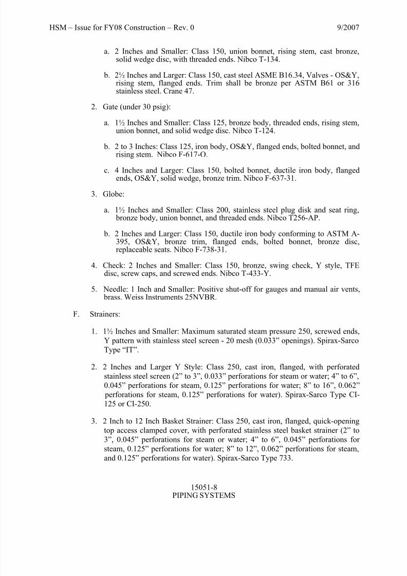
a. 2 Inches and Smaller: Class 150, union bonnet, rising stem, cast bronze,solid wedge disc, with threaded ends. Nibco T-134.
b. 2½ Inches and Larger: Class 150, cast steel ASME B16.34, Valves - OS&Y,rising stem, flanged ends. Trim shall be bronze per ASTM B61 or 316stainless steel. Crane 47.
2. Gate (under 30 psig):
a. 1½ Inches and Smaller: Class 125, bronze body, threaded ends, rising stem,union bonnet, and solid wedge disc. Nibco T-124.
b. 2 to 3 Inches: Class 125, iron body, OS&Y, flanged ends, bolted bonnet, andrising stem. Nibco F-617-O.
c. 4 Inches and Larger: Class 150, bolted bonnet, ductile iron body, flangedends, OS&Y, solid wedge, bronze trim. Nibco F-637-31.
3. Globe:
a. 1½ Inches and Smaller: Class 200, stainless steel plug disk and seat ring, bronze body, union bonnet, and threaded ends. Nibco T256-AP.
b. 2 Inches and Larger: Class 150, ductile iron body conforming to ASTM A-395, OS&Y, bronze trim, flanged ends, bolted bonnet, bronze disc,replaceable seats. Nibco F-738-31.
4. Check: 2 Inches and Smaller: Class 150, bronze, swing check, Y style, TFEdisc, screw caps, and screwed ends. Nibco T-433-Y.
5. Needle: 1 Inch and Smaller: Positive shut-off for gauges and manual air vents, brass. Weiss Instruments 25NVBR.
F. Strainers:
1. 1½ Inches and Smaller: Maximum saturated steam pressure 250, screwed ends,
Y pattern with stainless steel screen - 20 mesh (0.033” openings). Spirax-Sarco
Type “IT”.
2. 2 Inches and Larger Y Style: Class 250, cast iron, flanged, with perforated
stainless steel screen (2” to 3”, 0.033” perforations for steam or water; 4” to 6”,
0.045” perforations for steam, 0.125” perforations for water; 8” to 16”, 0.062”
perforations for steam, 0.125” perforations for water). Spirax-Sarco Type CI-
125 or CI-250.
3. 2 Inch to 12 Inch Basket Strainer: Class 250, cast iron, flanged, quick-opening
top access clamped cover, with perforated stainless steel basket strainer (2” to
3”, 0.045” perforations for steam or water; 4” to 6”, 0.045” perforations for
steam, 0.125” perforations for water; 8” to 12”, 0.062” perforations for steam,
and 0.125” perforations for water). Spirax-Sarco Type 733.
8/6/2019 15051 S Piping Systems
http://slidepdf.com/reader/full/15051-s-piping-systems 9/24
HSM – Issue for FY08 Construction – Rev. 0 9/2007
15051-9PIPING SYSTEMS
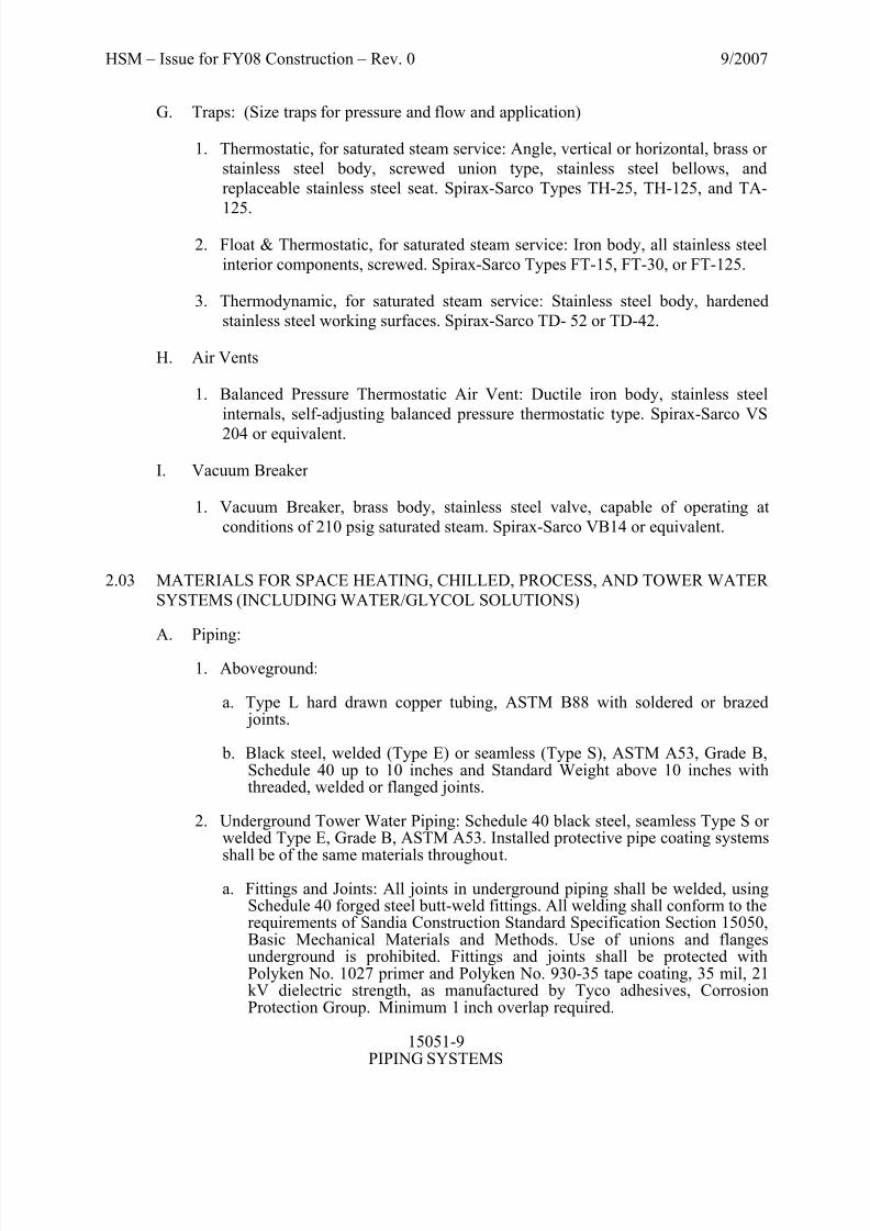
G. Traps: (Size traps for pressure and flow and application)
1. Thermostatic, for saturated steam service: Angle, vertical or horizontal, brass or
stainless steel body, screwed union type, stainless steel bellows, and
replaceable stainless steel seat. Spirax-Sarco Types TH-25, TH-125, and TA-
125.
2. Float & Thermostatic, for saturated steam service: Iron body, all stainless steel
interior components, screwed. Spirax-Sarco Types FT-15, FT-30, or FT-125.
3. Thermodynamic, for saturated steam service: Stainless steel body, hardened
stainless steel working surfaces. Spirax-Sarco TD- 52 or TD-42.
H. Air Vents
1. Balanced Pressure Thermostatic Air Vent: Ductile iron body, stainless steel
internals, self-adjusting balanced pressure thermostatic type. Spirax-Sarco VS
204 or equivalent.
I. Vacuum Breaker
1. Vacuum Breaker, brass body, stainless steel valve, capable of operating at
conditions of 210 psig saturated steam. Spirax-Sarco VB14 or equivalent.
2.03 MATERIALS FOR SPACE HEATING, CHILLED, PROCESS, AND TOWER WATER
SYSTEMS (INCLUDING WATER/GLYCOL SOLUTIONS)
A. Piping:
1. Aboveground:
a. Type L hard drawn copper tubing, ASTM B88 with soldered or brazed joints.
b. Black steel, welded (Type E) or seamless (Type S), ASTM A53, Grade B,Schedule 40 up to 10 inches and Standard Weight above 10 inches withthreaded, welded or flanged joints.
2. Underground Tower Water Piping: Schedule 40 black steel, seamless Type S or welded Type E, Grade B, ASTM A53. Installed protective pipe coating systems
shall be of the same materials throughout.a. Fittings and Joints: All joints in underground piping shall be welded, using
Schedule 40 forged steel butt-weld fittings. All welding shall conform to therequirements of Sandia Construction Standard Specification Section 15050,Basic Mechanical Materials and Methods. Use of unions and flangesunderground is prohibited. Fittings and joints shall be protected withPolyken No. 1027 primer and Polyken No. 930-35 tape coating, 35 mil, 21kV dielectric strength, as manufactured by Tyco adhesives, CorrosionProtection Group. Minimum 1 inch overlap required.

8/6/2019 15051 S Piping Systems
http://slidepdf.com/reader/full/15051-s-piping-systems 10/24
HSM – Issue for FY08 Construction – Rev. 0 9/2007
15051-10PIPING SYSTEMS
b. Protective pipe covering shall be factory or field applied according tomanufacturer’s written instructions. Products shall be Polyken No. 1027 primer and Polyken No 930-35 tape coating, 35 mil 21 kV dielectricstrength, as manufactured by Tyco adhesives, Corrosion Protection Group.Minimum 1 inch overlap required.
c. Epoxy Coatings: 3M epoxy coatings may be used in place of the Polyken pipe coatings. 3M Scotchkote 6233, Fusion-Bonded Epoxy Coating, shall be facility specified and applied at 15 MILs thickness for pipe and fittings.3M Scotchkote 323, Liquid Epoxy Coating, shall be facility specified andapplied at 25 MILs thickness. Epoxy coatings shall be applied according tomanufacturer’s written instructions.
B. Fittings:
1. Malleable-Iron Threaded Fittings: ASME B16.4, Class 150.
2. Malleable-Iron Unions: ASME B16.39, Class 150.
3. Wrought and Cast Copper and Copper Alloy Solder Joint Fittings: ASME
B16.18 and B16.22.
4. Forged Steel Threaded and Socket Weld Fittings: ASME B16.11, Class 2000
and 3000.
5. Wrought Steel Butt Welded Fittings: ASME B16.9, equal in thickness to meet
pipe pressure ratings.
6. Forged Steel Branch Fittings (weld-o-lets, thread-o-lets, etc.): MSS-SP-97,
with thickness to meet pipe pressure ratings.
7. Cast and Forged Steel Flanges: ASME B16.5, Class 150, Material Group 1.1,
welding neck, slip-on, or threaded, raised face (or faced to match adjoining
valves, components and equipment), and including bolts, nuts and gaskets.
8. Threaded brass fittings and nipples, ASTM B 43, ASTM B 687.
C. Gaskets: Material shall be of compressed sheet suitable for the operating conditions.Group 1a or 1b as listed in ASME B16.5.
D. Bolts and Nuts: Bolts shall conform to ASTM A193/A193M Rev B, Grade B7. Nutsshall conform to ASTM A194/A194M Rev A, Grade 2H.
E. Valves:
1. Gate:
a. 2 Inches and Smaller: Class 125, solder or threaded ends, bronze body,rising stem, screwed bonnet, and solid wedge. Nibco S-111 or Nibco T-111.

8/6/2019 15051 S Piping Systems
http://slidepdf.com/reader/full/15051-s-piping-systems 11/24
HSM – Issue for FY08 Construction – Rev. 0 9/2007
15051-11PIPING SYSTEMS
b. 2½ Inches and Larger: Class 125, flanged ends, OS&Y, iron body, bronzetrim, rising stem, and solid wedge. Nibco F-617-0.
2. Ball:
a. 2 Inches and Smaller: bronze body, blow-out proof captive stem, double
Teflon seats, full ported, stainless steel or chrome plated brass ball, 2-piece,threaded or soldered ends. Nibco T-585-70 or S-585-70. Or a 3-piece bronze body, full port, stainless steel trim, with a blowout-proof stem. Nibco T or S-595-Y. System drain applications may use a Nibco 585-70-HC.
b. 2½ Inches to 3 Inches: Two or three-piece bronze body, blow-out proof captive stainless steel stem, double Teflon seals and seats, full ported,stainless steel or chrome plated brass ball and threaded ends. Nibco T-585-70-66 or Nibco T-585-Y.
c. 4 Inches and Larger: Class 150, flanged ends, carbon steel body with 316stainless steel trim, uni-body design, full ported, blow-out proof captive
stainless steel stem and ball, and Teflon seat. Nibco F-510-CS-R-66-FS.
3. Globe:
a. 2 Inches and Smaller: Class 125, screwed ends, bronze body, inside screw,screw-in bonnet, renewable seat and disc. Nibco T-211.
b. 2½ Inches and Larger: Class 125, iron body conforming to ASTM A126Class B, bronze trim, flanged ends, bolted bonnet, bronze disc, replaceableseats. Nibco F-718-B.
4. Butterfly:
a. 2½ Inches through 6 Inches: 200 psi working pressure, ductile iron body,aluminum/bronze disc, EPDM liner, stainless steel shaft, resilient seat, O-ring seals, lug type for dead-end service, lever operator. Nibco LD2000series.
b. 8 Inches and Larger: 150 psi or 200 psi working pressure, ductile iron body,aluminum/bronze disc, EPDM liner, stainless steel shaft, resilient seat, O-ring seals, lug type for dead-end service, gear operator. Nibco LD1000 or LD2000 series dependent on the application.
5. Check Valve:
a.
2 Inches and Smaller: Class 125, threaded ends, bronze body, Y pattern,renewable seat and disk, and screw cap. Nibco T-413
b. 2½ Inches and Larger: Class 125, iron body, silent check, flanged ends,globe style, spring actuated, renewable seats and disc, bronze trim or 316stainless steel trim. Nibco F-910.
6. Vertical Check: 2 Inches and Smaller: Class 125, threaded ends, bronze body,spring actuated, inline vertical lift type, TFE seat ring. Nibco T-480-Y.

8/6/2019 15051 S Piping Systems
http://slidepdf.com/reader/full/15051-s-piping-systems 12/24
HSM – Issue for FY08 Construction – Rev. 0 9/2007
15051-12PIPING SYSTEMS
7. Needle: 1 Inch and Smaller: Rated at 600 psi and 300°F, positive shut-off for gauges, brass. Weiss Instruments 25NVBR.
F. Strainers:
1. 2 Inches and Smaller: Threaded ends, cast bronze body with screwed cap, and
20-mesh 304 stainless steel screen for water service. Watts series 777S.
2. 2½ Inches and Larger: Flanged ends, cast iron body and bolted cap, standardmesh, stainless steel screen for water service. Watts series 77-DI-125.
G. Flexible Connectors:
1. 2 Inches and Smaller: Threaded or socket ends, Type 321 stainless steel or bronze corrugated inner tube and wire braid outer shield, MetraFlex SST, BBT,or BBS.
2. 2½ Inches and Larger: Elastomer connector, solid plate steel, Class 150 flangedends, constructed of neoprene and nylon, temperature rated at no less than
240°F. Control units must be installed per manufacturer’s instructions.MetraFlex Metrasphere style O.
H. Glycol-Resistant Materials: All materials installed in a system containing awater/glycol solution shall be resistant to (compatible with) glycol. Suitablematerials include steel, iron, and bronze (red brass).
I. Bypass Feeder/Chemical Filter feeder: Chemical by-pass feeder shall be installed onall heating and chilled water loops and piped according to mechanical standarddrawing MP5013STD.dgn, detail no. 15J-17. The by-pass feeder shall be either a 2or 5 gallon Efficiency Dynamics Inc. No. FF-100 filter feeder capable of: anoperating pressure up to 150 psig, operating temperature up to 200ºF, and flow up to40 gpm/maximum initial pressure drop of 3 psi. The feeder shall contain a stainlesssteel filter bag screen, with polypropylene replacement bag filter.
J. Calibrated Balancing Valves, 2 Inches and Smaller: Bronze body, ball type, 200 psig working pressure, 250 deg F maximum operating temperature, and havingthreaded ends. Valves shall have calibrated orifice or venturi, connections for portable differential pressure meter with integral seals, and shall be equipped with amemory stop to retain set position. Bell and Gossett Series Model CB. Providecalibration curves with submittals. Size valves for operation in the midsection of curves at the coils specified flow rate.
K. Calibrated Balancing Valves, 2-1/2 Inches and Larger: Cast-iron or steel body, ballor globe type, 175-psig working pressure, 250° F maximum operating temperature,
and having flanged connections. Valves shall have calibrated orifice or venturi,connections for portable differential pressure meter with integral seals, and shall beequipped with a memory stop to retain set position. Bell and Gossett Series ModelCB. Provide calibration curves with submittals. Size valves for operation in themidsection of curves at the coils specified flow rate.
L. Flexible hose and fitting: ¼” – ¾” hose and fitting for final lab equipmentconnection assemblies. Synthetic rubber tube, textile braid reinforcement, polyester braided cover, low pressure hose. Operating temperature range: -40° F to 212° F,water not to exceed 150° F, air not to exceed 165° F. Aeroquip FC647 hose with

8/6/2019 15051 S Piping Systems
http://slidepdf.com/reader/full/15051-s-piping-systems 13/24
HSM – Issue for FY08 Construction – Rev. 0 9/2007
15051-13PIPING SYSTEMS
Aeroquip Socketless™ hose fittings. Flexible hose connections are not permitted inconcealed areas or for heating and cooling coil installations.
2.04 MATERIALS FOR FUEL GAS AND LIQUIFIED PROPANE GAS SYSTEMS
(ABOVEGROUND, FOR UNDERGROUND FUEL GAS PIPING, SEE SANDIA
CONSTRUCTION STANDARD SPECIFICATION SECTION 02553, EXTERIOR GASPIPING SYSTEMS)
A. Piping: Schedule 40 black steel for indoor use, schedule 40 galvanized steel or epoxy painted schedule 40 black steel for outdoor aboveground use, seamless TypeS or welded Type E, ASTM A53/A53M.
B. Fittings:
1. 2 Inches and Smaller: Class 150, banded malleable iron, screwed, ASME B16.3.Galvanized fittings shall be hot dipped in accordance ASTM A153
2.
2½ Inches and Larger: Class 150, banded malleable iron, screwed, ASMEB16.3, or Schedule 40 wrought steel butt-weld fittings, ASME B16.9.
C. Valves: Shutoff valves shall be constructed of materials compatible with the piping.Shutoff valves installed in a portion of a piping system operating above 0.5 psig,and outdoors shall comply with ASME B16.33. Shutoff valves installed in a portionof a piping system operating at 0.5 psig or less shall comply with ANSI Z21.15 or ASME B16.33.
1. Plug:
a. Outdoor systems, 2 Inches and Smaller: Zinc iron body, threaded ends, flathead lockwing, lubricated brass plug, 175 psig rating, A.Y. McDonald
Series 560G.
b. Outdoor systems, 2½ Inches and Greater: Iron body, flanged ends,lubricated plug, 150 psi CWP, Flowserve Nordstrom Fig. 115, or 143.
c. Indoor systems, appliance shutoff valve: Brass body and plug, lockwinghead, threaded ends, 25 psig rating, A.Y. McDonald Series 10621.
2. Ball:
a. Outdoor systems operating above 0.5 psig: 100% full port, hot forged brass body, double viton o-rings, PTFE seats, integral lockout device, valve
certified to 175 psig. Jomar model no. 175LWN.
b. Appliance equipment applications, systems operating at less than 0.5 psig:Forged brass body, fluorocarbon o-rings, PTFE seats, valve certified to 0.5 psig. Nibco GB or TFB Series.
D. Appliance Connectors, systems operating at less than 0.5 psig: Stainless steel or coated stainless steel, corrugated, ANSI Z21.24, Connectors for Gas Appliances,certified for indoor and outdoor use. Brasscraft model no. SSC or CSSC.

8/6/2019 15051 S Piping Systems
http://slidepdf.com/reader/full/15051-s-piping-systems 14/24
HSM – Issue for FY08 Construction – Rev. 0 9/2007
15051-14PIPING SYSTEMS
E. Strainer:
1. Outdoor systems:
a. 2 Inches and Smaller: Cast Iron body, threaded wye pattern, 400 WOG,304SS standard screen. Watts Regulator Series 77SI.
b. 2-1/2 Inches and Larger: Cast Steel body, flanged wye pattern, 285 WOG,304SS standard screen. Watts Regulator Series 77F-CSI.
2. Indoor Systems:
a. Cast Bronze body, threaded wye pattern, 400 WOG, 304SS standard screen.Watts Regulator Series 777S.
2.05 MATERIALS FOR COMPRESSED AIR SYSTEMS (200 PSIG AND UNDER)
A. General: Materials shall be as follows unless otherwise indicated on the applicable
contract drawings.
B. Pipe, joints, and fittings to be used for modifications or additions shall be of thesame material (steel or copper) as the existing systems being modified but shallconform to the following unless otherwise indicated on the applicable contractdrawings. All copper joints in compressed air service greater than 60 psig or servicetemperatures (any media) greater than 200ºF shall be brazed.
C. Piping:
1. Aboveground: Cleaned for oxygen service, Type L, hard drawn copper tubing,ASTM B88 or ASTM B819, or hard drawn ACR copper tubing of equalinternal diameter, ASTM B280. Steel piping for modifications to existingsystems, schedule 40 black steel, seamless or welded per ASTM A53.
2. Underground: Cleaned for oxygen service, Type L, hard drawn copper tubing,ASTM B88 or ASTM B819, or hard drawn ACR copper tubing, ASTM B280.Steel pipe for modification to existing systems: Schedule 40 black steel,seamless Type S or welded Type E, Grade A or B, ASTM A53. Installed protective pipe coating systems shall be of the same materials throughout.
a. Pipe and Fittings:
(1) Steel: Protective pipe covering shall be factory or field appliedaccording to manufacturer’s written instructions. Coatings shall
extend above grade at least 6 inches. Products shall be Polyken No.1027 primer and Polyken No. 930-35 tape coating, 35 mil, 21 kVdielectric strength, as manufactured by Tyco adhesives, CorrosionProtection Group. Minimum 1 inch overlap required. EpoxyCoatings: 3M epoxy coatings may be used in place of the Polyken pipe coatings. 3M Scotchkote 6233, Fusion-Bonded Epoxy Coating,shall be facility specified and applied at 15 MILs thickness for pipeand fittings. Epoxy coatings shall be applied according tomanufacturer’s written instructions.

8/6/2019 15051 S Piping Systems
http://slidepdf.com/reader/full/15051-s-piping-systems 15/24
HSM – Issue for FY08 Construction – Rev. 0 9/2007
15051-15PIPING SYSTEMS
(2) Copper: Protective pipe covering shall be factory or field appliedaccording to manufacturer’s written instructions. Coatings shallextend above grade at least 6 inches. Products shall be Polyken No.1027 primer and Polyken No. 930-35 tape coating, 35 mil, 21 kVdielectric strength, as manufactured by Tyco adhesives, CorrosionProtection Group. Minimum 1 inch overlap required.
b. Joints:
(1) Steel: All joints in underground piping shall be welded, usingSchedule 40 forged steel butt-weld fittings. All welding shallconform to the requirements of Sandia Construction StandardSpecification Section 15050, Basic Mechanical Materials andMethods. Use of unions underground is prohibited. Fittings and joints shall be protected with Polyken No. 1027 primer and Polyken No. 930 tape coating as manufactured by Tyco Adhesives, CorrosionProtection Group. Epoxy Coatings: 3M epoxy coatings may be usedin place of the Polyken pipe coatings. 3M Scotchkote 323, LiquidEpoxy Coating, shall be facility specified and applied at 25 MILs
thickness. Epoxy coatings shall be applied according tomanufacturer’s written instructions.
(2) Copper: All joints shall be brazed with an argon or nitrogen purgeapplied. Use of unions underground is prohibited. Fittings and jointsshall be protected with Polyken No. 1027 primer and Polyken No.930 tape coating as manufactured by Tyco Adhesives, CorrosionProtection Group.
D. Fittings:
1. Wrought copper and bronze braze-joint, ASME B16.22, ASTM B88. Threaded brass fittings and nipples, ASTM B 43, ASTM B 687. For modifications toexisting steel systems: Class 150 banded malleable iron, screwed, ASMEB16.3; Schedule 40 wrought steel butt-weld fittings, ASME B16.9.
2. Flanges: Flanges shall be Class 150 bronze flanges, ASME B16.24, or for amodification to an existing steel system: Class 150 forged steel flangesconforming to ASME B16.5.
E. Gaskets: Material shall be of compressed sheet suitable for the operating conditions.Group 1a or 1b as listed in ASME B16.5.
F. Bolts and Nuts: Bolts shall conform to ASTM A193/A193M Rev A, Grade B7. Nutsshall conform to ASTM A194/A194M Rev A, Grade 2H.
G. Flexible Connectors:
1. 2 Inches and Smaller: Threaded or socket ends, corrugated inner tube and wire braid outer shield, Type 321 stainless steel. MetraFlex SST.
2. 2½ Inches to 6 Inches: Flanged ends, corrugated inner tube and wire braid outer shield, Type 321 stainless steel. MetraFlex MLP or SLP.
H. Valves:

8/6/2019 15051 S Piping Systems
http://slidepdf.com/reader/full/15051-s-piping-systems 16/24
HSM – Issue for FY08 Construction – Rev. 0 9/2007
15051-16PIPING SYSTEMS
1. Gate:
a. 3 Inches and Smaller: Class 150, threaded ends, bronze body, rising stem,union bonnet and solid wedge. Nibco T-134.
b. 4 Inches and Larger: Class 150, flanged ends, OS&Y, cast steel or ductile
iron body, bronze trim, bolted bonnet, rising stem. Nibco F-637-31 or equivalent.
2. Ball:
a. 2 Inches and Smaller: 600 psi CWP, bronze body, blow-out proof captivestainless steel stem, double Teflon seals and seats, full ported stainless steel ball. Nibco T-585, 2-piece and threaded ends or Nibco S-595-Y-66, 3-pieceand solder ends.
b. 2½ Inches and Larger: Class 150, flanged ends, carbon steel body with 316stainless steel trim, blow-out proof captive stainless steel stem and ball,double Teflon seals and seats. Nibco F510 Series.
3. Needle: 1 Inch and Smaller: Rated at 600 psi and 300ºF, positive shut-off for gauges, brass. Weiss Instruments 25NVBR.
2.06 MATERIALS FOR PROCESS VACUUM SYSTEMS
A. General: Materials shall be as follows unless otherwise indicated on the applicablecontract drawings.
B. Pipe and fittings to be used for modifications or additions shall be the same material(steel, copper or plastic) as the existing systems being modified but shall conform tothe following unless otherwise indicated on the applicable contract drawings.
C. Piping:
1. Type L hard-drawn copper tubing with soldered joints, ASTM B88, or Type304 stainless steel or CPVC. Schedule 80, ASTM F441.
D. Fittings:
1. Wrought copper and bronze solder-joint, ASME B16.22; or Schedule 40wrought steel butt-weld fittings, ASME B16.9, or CPVC schedule 80, ASTM F437.
2. ¼-Inch to 2-Inch Tube Fittings: Carbon steel and 316 stainless steel. Swagelok.
3. ¼-Inch to 1-Inch Weld Fittings: Carbon steel, 316 stainless steel. Cajon.
E. Flanges: Flanges shall conform to ASME B16.5.
F. Gaskets: Material shall be of compressed sheet suitable for the operating conditions.Group 1a or 1b of ASME B16.5.

8/6/2019 15051 S Piping Systems
http://slidepdf.com/reader/full/15051-s-piping-systems 17/24
HSM – Issue for FY08 Construction – Rev. 0 9/2007
15051-17PIPING SYSTEMS
G. Bolts and Nuts: Bolts shall conform to ASTM A193, Grade B7. Nuts shall conformto ASTM A194, Grade 2H.
H. Valves:
1. Ball: Vacuum service to Class 125.
a. 2 Inches and Smaller: Class 125 screwed or soldered ends, bronze body, andO-ring seal swing-out body, Worcester Series 44.
b. 2½ Inches and Larger: Class 125, flanged ends, bronze O-ring seal,Worcester Series 45.
c. CPVC body, EPDM o-ring seals, true-union design, rated for full vacuumservice. Asahi/America Type 21 Duo-Bloc Ball Valve
2. Needle: 1 Inch and Smaller: Positive shut-off for gauges and manual air vents, brass. Weiss Instruments 25NVBR or equivalent.
2.07 EQUIPMENT
A. General: Equipment required for installation on this contract shall be as specified onthe applicable contract drawings and shall be furnished complete with allaccessories normally supplied with the catalog item listed and all other accessoriesnecessary for a complete and satisfactory operating system.
B. Compressed Air Receivers:
1. Prior to installation and acceptance, a pressure vessel operated at pressures of 15 psig or greater furnished under this contract will be stamped with an ASMEBoiler and Pressure Vessel Code Symbol and a National Board of Boiler andPressure Vessel Inspector’s number. This will certify that the vessel has beenfabricated and tested per the provisions of the ASME Boiler and PressureVessel Code. Manufacturers’ data reports (unless exempted by the ASMECode) will be filed with the National Board in Columbus, Ohio. Two copies of these data reports shall be submitted to Sandia National Laboratories. Testing,certification, and registration will be at the expense of the Contractor. ASTMA-515 and ASME SA-515 type steels shall not be used in the fabrication of pressure vessels.
2. Receiver shall be equipped with shut-off valve and properly sized ASMEcertified pressure relief valve.
C. Pressure Relief Valves: Valves shall be ASME National Board certified, registeredand stamped. The valves shall be factory set to maintain an operating or standby pressure as directed or noted.
D. Thermometers and Thermowells: Thermometers shall be the bi-metal dial type,digital vari-angle, direct or remote mounted with an adjustable angle dial face,union NPT connection, stainless steel case (bi-metal type), Hi-impact ABS case(digital type). Each thermometer shall be provided with a separable brassthermowell consisting of a properly sized bore. The well shall be the length required

8/6/2019 15051 S Piping Systems
http://slidepdf.com/reader/full/15051-s-piping-systems 18/24

8/6/2019 15051 S Piping Systems
http://slidepdf.com/reader/full/15051-s-piping-systems 19/24
HSM – Issue for FY08 Construction – Rev. 0 9/2007
15051-19PIPING SYSTEMS
service. Only eccentric reducers will be permitted in steam applications. Cast bushings ARE NOT acceptable.
C. Unions: All piping unions shall be of the ground joint type, constructed frommaterials equivalent in alloy composition and strength to other fittings specifiedwith which they are used. Union pressure classes and end connections shall be the
same as the fittings used in the lines with the unions.
1. Joining dissimilar materials (copper to steel). Use brass nipples, brass valves or brass unions between copper and steel piping 2 inches and smaller. Usedielectric flange kits on larger piping. Dielectric unions shall not be used to jointwo dissimilar metals (ferrous and non-ferrous metallic piping.)
D. Installation of Valves: Valves shall be installed at the locations shown on thedrawings and where specified. All valves shall be installed with their stemshorizontal or above and with sufficient clearance to allow the inspection and repair of two-piece and three-piece valves in place.
E. Piping Equipment Supports and Fastenings: Fixtures and equipment shall be solidly
supported and securely fastened. Installation shall include suitable backing toanchor all hanging fixtures and equipment.
F. Air Vents (for Closed Loop Water and Water/Glycol Systems):
1. Automatic Air Vents: A manual valve shall be installed ahead of each automaticair vent. Brass body, for use on hot or cold water, with threaded outletadaptable to ¼” O.D. copper tube.
a. Do not install automatic vent valves in a glycol system.
b. A drain line should be connected to the vent hole and piped to the nearestfloor drain or floor sink.
2. Manual: A shutoff valve shall be installed ahead of each manual air vent.Where air vent locations are 10’-0” or more above the floor, ¼” O.D. copper tubing shall be installed at the point of venting and extended down with theneedle valve installed to an accessible position. All vents lower than 10 feetshall have a candy cane installed that would allow easy access for venting in a bucket. All vents that would become inaccessible after the completion of construction shall be extended to an accessible location. Each branch and mainsystem high point shall be vented to permit removal of all air from the system.
G. Equipment Connections: All piping connections to pumps and other equipment shall be installed without strain at the pipe connection of the equipment. The Contractor
shall be required as directed by the Sandia Delegated Representative (SDR) toremove the bolts in flanged connections or disconnect piping to demonstrate that the piping has been so connected. Pipe connections to equipment shall be made withunions or flanged fittings.
H. Joints:
1. Flanged Joints: All flanged joints shall be face matched. Raised face flangesshall not be mated to flat-faced cast-iron flanges on valves or equipment. Theraised face must be machined flush. All flange bolt holes shall straddle the

8/6/2019 15051 S Piping Systems
http://slidepdf.com/reader/full/15051-s-piping-systems 20/24
HSM – Issue for FY08 Construction – Rev. 0 9/2007
15051-20PIPING SYSTEMS
horizontal and vertical centerlines unless otherwise noted. Install insulating kitson flanges connecting dissimilar metals such as steel to copper in order to prevent electrolytic action. Bolting shall comply with ASME B31.3, ProcessPiping. Torque values and tightening sequence for bolts shall be in accordancewith flange manufacturer’s instructions.
2. Screwed Joints: Screwed pipe joints shall have American Standard Taper PipeThreads complying with ASME B1.2. Care shall be taken that the inside of pipeis thoroughly clean and free of cutting oil and foreign matter before installation.Metal screwed pipe joints shall be made leak-tight by the use of Teflon tape, pipe thread lubricant, or Teflon tape and a pipe-lubricating compound.
3. Solder-Joints: Tubing shall be cut square, reamed, and burrs removed. Both theinside of fittings and the outside of tubing shall be well cleaned with sand clothor wire brush before sweating. Care shall be taken to prevent annealing of fittings and hard drawn tubing when making connections. Solders containinglead or cored solders are not permitted. Joints shall conform to ASTM B828.Joints shall comply with ASME B31.3, Process Piping and the Copper Development Association.
a. Solder containing antimony SHALL NOT be used to join metals containingzinc (e.g., galvanized iron, galvanized steel, and brass).
b. Use sand cloth or a stainless steel wire brush to clean surfaces to be joined.
c. Solder end valve: Use a gate, globe, two-piece or three-piece ball valve for solder end valves. When joining a solder end valve, ensure valve is fullyopen. Apply heat to tube first. Transfer as much heat as possible through thetube to the valve. Avoid prolonged heating of the valve. Use a non-corrosive paste flux and solid wire solder suitable for the servicetemperatures and pressures expected.
4. Brazed Joints: New copper systems shall be installed with socket type fittingsand with an argon or nitrogen purge applied. Flux shall not be used exceptwhere joining specialty items and fittings that are not available in copper.Brazing filler metals shall comply with AWS A5.8, Specification for BrazingFiller Metals. Copper-to-copper joints shall be brazed using a copper- phosphorus or copper-phosphorous-silver brazing filler metal (BCuP) withoutflux. Copper-to-bronze or copper-to-brass joints shall be brazed using anappropriate flux with 45% silver (Bag-5 series) brazing filler metal. Thefollowing procedure shall be followed:
a. Tube ends shall be cut square using a sharp tubing cutter. The wheel shall befree from grease, oil, or dirt. The cut end of the tubing shall be deburred
with a sharp, clean deburring tool, taking care to prevent chips fromentering the tube or pipe.
b. The surfaces to be brazed shall be mechanically cleaned. Joints shall be re-cleaned if they become contaminated prior to brazing. Joints shall be brazedwithin 1 hour of being cleaned.
c. Where dissimilar metal joints, such as copper to bronze or brass, are being brazed, flux shall be applied sparingly to minimize contamination of theinside of the tube with flux. Where possible, short sections of copper tube
8/6/2019 15051 S Piping Systems
http://slidepdf.com/reader/full/15051-s-piping-systems 21/24
HSM – Issue for FY08 Construction – Rev. 0 9/2007
15051-21PIPING SYSTEMS
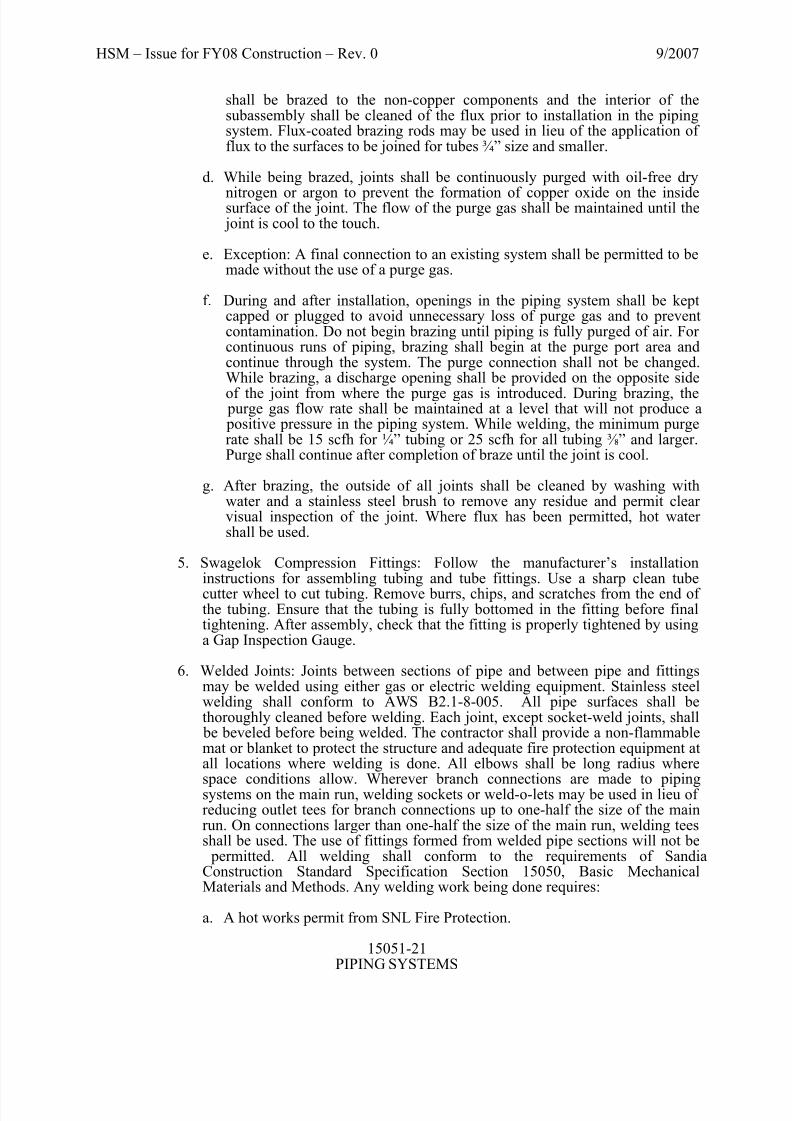
shall be brazed to the non-copper components and the interior of thesubassembly shall be cleaned of the flux prior to installation in the pipingsystem. Flux-coated brazing rods may be used in lieu of the application of flux to the surfaces to be joined for tubes ¾” size and smaller.
d. While being brazed, joints shall be continuously purged with oil-free dry
nitrogen or argon to prevent the formation of copper oxide on the insidesurface of the joint. The flow of the purge gas shall be maintained until the joint is cool to the touch.
e. Exception: A final connection to an existing system shall be permitted to bemade without the use of a purge gas.
f. During and after installation, openings in the piping system shall be keptcapped or plugged to avoid unnecessary loss of purge gas and to preventcontamination. Do not begin brazing until piping is fully purged of air. For continuous runs of piping, brazing shall begin at the purge port area andcontinue through the system. The purge connection shall not be changed.While brazing, a discharge opening shall be provided on the opposite side
of the joint from where the purge gas is introduced. During brazing, the purge gas flow rate shall be maintained at a level that will not produce a positive pressure in the piping system. While welding, the minimum purgerate shall be 15 scfh for ¼” tubing or 25 scfh for all tubing ⅜” and larger.Purge shall continue after completion of braze until the joint is cool.
g. After brazing, the outside of all joints shall be cleaned by washing withwater and a stainless steel brush to remove any residue and permit clear visual inspection of the joint. Where flux has been permitted, hot water shall be used.
5. Swagelok Compression Fittings: Follow the manufacturer’s installationinstructions for assembling tubing and tube fittings. Use a sharp clean tubecutter wheel to cut tubing. Remove burrs, chips, and scratches from the end of the tubing. Ensure that the tubing is fully bottomed in the fitting before finaltightening. After assembly, check that the fitting is properly tightened by usinga Gap Inspection Gauge.
6. Welded Joints: Joints between sections of pipe and between pipe and fittingsmay be welded using either gas or electric welding equipment. Stainless steelwelding shall conform to AWS B2.1-8-005. All pipe surfaces shall bethoroughly cleaned before welding. Each joint, except socket-weld joints, shall be beveled before being welded. The contractor shall provide a non-flammablemat or blanket to protect the structure and adequate fire protection equipment atall locations where welding is done. All elbows shall be long radius where
space conditions allow. Wherever branch connections are made to pipingsystems on the main run, welding sockets or weld-o-lets may be used in lieu of reducing outlet tees for branch connections up to one-half the size of the mainrun. On connections larger than one-half the size of the main run, welding teesshall be used. The use of fittings formed from welded pipe sections will not be permitted. All welding shall conform to the requirements of SandiaConstruction Standard Specification Section 15050, Basic MechanicalMaterials and Methods. Any welding work being done requires:
a. A hot works permit from SNL Fire Protection.
8/6/2019 15051 S Piping Systems
http://slidepdf.com/reader/full/15051-s-piping-systems 22/24
HSM – Issue for FY08 Construction – Rev. 0 9/2007
15051-22PIPING SYSTEMS
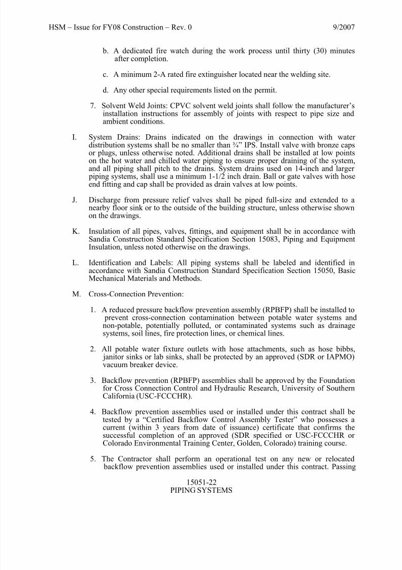
b. A dedicated fire watch during the work process until thirty (30) minutesafter completion.
c. A minimum 2-A rated fire extinguisher located near the welding site.
d. Any other special requirements listed on the permit.
7. Solvent Weld Joints: CPVC solvent weld joints shall follow the manufacturer’sinstallation instructions for assembly of joints with respect to pipe size andambient conditions.
I. System Drains: Drains indicated on the drawings in connection with water distribution systems shall be no smaller than ¾” IPS. Install valve with bronze capsor plugs, unless otherwise noted. Additional drains shall be installed at low pointson the hot water and chilled water piping to ensure proper draining of the system,and all piping shall pitch to the drains. System drains used on 14-inch and larger piping systems, shall use a minimum 1-1/2 inch drain. Ball or gate valves with hoseend fitting and cap shall be provided as drain valves at low points.
J. Discharge from pressure relief valves shall be piped full-size and extended to anearby floor sink or to the outside of the building structure, unless otherwise shownon the drawings.
K. Insulation of all pipes, valves, fittings, and equipment shall be in accordance withSandia Construction Standard Specification Section 15083, Piping and EquipmentInsulation, unless noted otherwise on the drawings.
L. Identification and Labels: All piping systems shall be labeled and identified inaccordance with Sandia Construction Standard Specification Section 15050, BasicMechanical Materials and Methods.
M. Cross-Connection Prevention:
1. A reduced pressure backflow prevention assembly (RPBFP) shall be installed to prevent cross-connection contamination between potable water systems andnon-potable, potentially polluted, or contaminated systems such as drainagesystems, soil lines, fire protection lines, or chemical lines.
2. All potable water fixture outlets with hose attachments, such as hose bibbs, janitor sinks or lab sinks, shall be protected by an approved (SDR or IAPMO)vacuum breaker device.
3. Backflow prevention (RPBFP) assemblies shall be approved by the Foundationfor Cross Connection Control and Hydraulic Research, University of Southern
California (USC-FCCCHR).
4. Backflow prevention assemblies used or installed under this contract shall betested by a “Certified Backflow Control Assembly Tester” who possesses acurrent (within 3 years from date of issuance) certificate that confirms thesuccessful completion of an approved (SDR specified or USC-FCCCHR or Colorado Environmental Training Center, Golden, Colorado) training course.
5. The Contractor shall perform an operational test on any new or relocated backflow prevention assemblies used or installed under this contract. Passing
8/6/2019 15051 S Piping Systems
http://slidepdf.com/reader/full/15051-s-piping-systems 23/24
HSM – Issue for FY08 Construction – Rev. 0 9/2007
15051-23PIPING SYSTEMS
backflow preventers shall be labeled with a tag indicating the test performed,the tester’s initials, and the date. Testing documentation shall be submitted tothe Sandia Delegated Representative (SDR).
6. Repairs to RPBFPs shall be made with original manufacturer’s parts.
7. Piping downstream of RPBFPs shall be labeled “Non-potable” or “NPW” inaccordance with Sandia Construction Standard Specification Section 15050,“Basic Mechanical Materials and Methods”.
8. RPBFP devices shall be installed at a maximum distance of 5 feet from finishedfloor with a 1 foot clearance maintained on all sides for ease of maintenance.
9. Adequate drainage shall be provided for the RPBFP and meet the following:
a. Discharge shall be piped full size (of the relief valve) and extend to alocation shown on project drawings.
b. Discharge piping shall be sloped minimum 1/8” per foot.
N. Compressed Air Receivers: Install receiver with sufficient clearance to allow accessto manhole or armhole.
O. Instrumentation: Local temperature and pressure instrumentation located inmechanical equipment rooms shall be of industrial quality and should be easily readfrom a normal vantage point from within the area. If instrumentation is placed in piping or ducts 10’ above the finished floor, a large 5-inch dial shall be used for ease of reading. Local instrumentation installed on point-of-use equipment shall beof a commercial utility quality, and that can be easily read from a vantage point near the equipment. Outdoor instrumentation shall be protected with weather shields.
3.02 TESTS
A. General:
Before insulation is applied, all piping, equipment, and accessories installed under
this contract shall be inspected and pressure tested by the Contractor in the presence
of the Sandia Delegated Representative (SDR) and approved before acceptance. The
Contractor shall furnish all labor, material, and equipment required for testing. The
use of data logging instrumentation is recommended for testing. The Contractor
shall be responsible for all repairs and retesting as required. All instruments and
equipment whose safe pressure range is below that of the test pressure shall be
removed from the line or blanked off before applying the tests. Submittal data shall be used as proof of pressure rating.
1. For test, the contractor shall provide a 4 inch diameter pressure gauge of maximum 1% full scale accuracy, maximum 300 PSIG range and maximum 2PSIG graduations. 100 PSIG for LPS & fuel gas.
B. Testing:

8/6/2019 15051 S Piping Systems
http://slidepdf.com/reader/full/15051-s-piping-systems 24/24
HSM – Issue for FY08 Construction – Rev. 0 9/2007
15051 24
1. Steam, condensate, hot water, chilled water, process water, and tower water piping shall be tested hydrostatically at the test pressures specified and shallshow no drop in pressure in a 2-hour period.
2. Fuel gas and compressed air piping shall be tested using compressed air or drynitrogen as indicated at the test pressures specified and shall show no drop in
pressure in a 2-hour period. Immediately after fuel gas is turned on into a newsystem, the piping shall be tested for leakage; gas leaks shall be located by soaptesting.
3. Process Vacuum piping shall be tested using a 23-inch Hg vacuum and shallshow no rise in pressure for 15 minutes; vacuum leaks shall be located byultrasonic leak detection. DO NOT use pressure testing on plastic pipingsystems! Severe damage or bodily injury can result.
C. Test Pressures:
Unless otherwise specified or noted below, hydrostatic test pressure shall be 1.5
times the system operating pressure and pneumatic test pressure shall be 1.25 timesthe system operating pressure, whichever is greater.
TEST PRESSURE (psig or vacuum)
SYSTEM Hydrostatic Pneumatic Vacuum
Steam System 125 to 30 psig 225 -- --
Steam System 30 psig & lower 50 -- --
Condensate System 100 -- --
Heating Water, Chilled Water,
Process Water and Tower Water
Systems
100 -- --
Fuel Gas System -- 25 --Compressed Air System above 60
psig
-- 250 --
Process Vacuum System -- -- 23” Hg
D. Flushing and Cleaning:
Coordination for flushing and cleaning of the systems shall be through the SDR to
ensure that all systems, components and controls are in place to execute the SNL
Construction Standard Specification 15189 Chemical Treatment.
END OF SECTION 15051