15 lb 6 in. 8 in. 15 lb
TRANSCRIPT

319
© 2014 Pearson Education, Inc., Upper Saddle River, NJ. All rights reserved. This material is protected under all copyright laws as they currentlyexist. No portion of this material may be reproduced, in any form or by any means, without permission in writing from the publisher.
Ans:tBC = 2.36 ksitAB = 7.82 ksi,
5–11. The assembly consists of two sections of galvanizedsteel pipe connected together using a reducing coupling at B. The smaller pipe has an outer diameter of 0.75 in. andan inner diameter of 0.68 in., whereas the larger pipe has anouter diameter of 1 in. and an inner diameter of 0.86 in. Ifthe pipe is tightly secured to the wall at C, determine themaximum shear stress developed in each section of the pipewhen the couple shown is applied to the handles of the wrench.
C
B
A
15 lb 6 in.
15 lb
8 in.
Ans.
Ans.tBC =
Tc
J=
210(0.5)p2 (0.54
- 0.434)= 2.36 ksi
tAB =
Tc
J=
210(0.375)p2 (0.3754
- 0.344)= 7.82 ksi
Hibbeler_Chapter 5(309-374).qxd 2/7/13 1:27 PM Page 319

321
© 2014 Pearson Education, Inc., Upper Saddle River, NJ. All rights reserved. This material is protected under all copyright laws as they currentlyexist. No portion of this material may be reproduced, in any form or by any means, without permission in writing from the publisher.
Ans:Use t = 25 mm
5–13. If the tubular shaft is made from material having anallowable shear stress of determine therequired minimum wall thickness of the shaft to the nearestmillimeter. The shaft has an outer diameter of 150 mm.
tallow = 85 MPa,
Internal Loadings: The internal torques developed in segments AB, BC, and CDof the assembly are shown in their respective free-body diagrams shown in Figs. a, b, and c.
Allowable Shear Stress: Segment BC is critical since it is subjected to the greatest
internal torque. The polar moment of inertia of the shaft is
Thus, the minimum wall thickness is
Ans.t = co - ci = 75 - 50.22 = 24.78 mm = 25 mm
ci = 0.05022 m = 50.22 mm
tallow =
TBC c
J; 85(106) =
45(103)(0.075)
p
2(0.0754
- ci
4)
J =
p
2 (0.0754
- ci4) .
A
EB
DF
C15 kN�m
30 kN�m
75 kN�m
30 kN�m
Hibbeler_Chapter 5(309-374).qxd 2/7/13 1:27 PM Page 321

339
© 2014 Pearson Education, Inc., Upper Saddle River, NJ. All rights reserved. This material is protected under all copyright laws as they currentlyexist. No portion of this material may be reproduced, in any form or by any means, without permission in writing from the publisher.
Ans:(tBC)max = 3.11 MPa(tAB)max = 1.04 MPa,
Ans.
Ans.(tBC)max =
TC
J=
9.549 (0.0125)p2(0.01254)
= 3.11 MPa
(tAB)max =
TC
J=
3.183 (0.0125)p2(0.01254)
= 1.04 MPa
TA =
13
TC = 3.183 N # m
TC =
P
v=
3(103)
50(2p)= 9.549 N # m
5–31. The solid steel shaft AC has a diameter of 25 mmand is supported by smooth bearings at D and E. It iscoupled to a motor at C, which delivers 3 kW of power tothe shaft while it is turning at 50 If gears A and Bremove 1 kW and 2 kW, respectively, determine themaximum shear stress developed in the shaft within regionsAB and BC. The shaft is free to turn in its support bearingsD and E.
rev>s.
ACB ED
1 kW
2 kW 3 kW
25 mm
Hibbeler_Chapter 5(309-374).qxd 2/7/13 1:27 PM Page 339

346
© 2014 Pearson Education, Inc., Upper Saddle River, NJ. All rights reserved. This material is protected under all copyright laws as they currentlyexist. No portion of this material may be reproduced, in any form or by any means, without permission in writing from the publisher.
Ans:dB = 16.8 mmdA = 12.4 mm,
Internal Torque: For shafts A and B
Allowable Shear Stress: For shaft A
Ans.
For shaft B
Ans. dB = 0.01683 m = 16.8 mm
85 A106 B =
79.58 AdB
2 Bp2 AdB
2 B4
tmax = tallow =
TB c
J
dA = 0.01240 m = 12.4 mm
85 A106 B =
31.83 AdA
2 Bp2 AdA
2 B4
tmax = tallow =
TA c
J
TB =
P
vB=
3001.20p
= 79.58 N # m
P = 300 W = 300 N # m>s
vB = vAa rA
rBb = 3.00pa0.06
0.15b = 1.20p rad>s
TA =
P
vA=
3003.00p
= 31.83 N # m
P = 300 W = 300 N # m>svA = 90
revmin
a2p radrev
b 1 min60 s
= 3.00p rad>s
5–38. The motor A develops a power of 300 W and turnsits connected pulley at 90 rev min. Determine the requireddiameters of the steel shafts on the pulleys at A and B if theallowable shear stress is tallow = 85 MPa.
> 60 mm
150 mm
90 rev/min
A
BBB
Hibbeler_Chapter 5(309-374).qxd 2/7/13 1:27 PM Page 346

354
© 2014 Pearson Education, Inc., Upper Saddle River, NJ. All rights reserved. This material is protected under all copyright laws as they currentlyexist. No portion of this material may be reproduced, in any form or by any means, without permission in writing from the publisher.
6 in.
A B
Ans:
Use di = 158
in.
5–46. A motor delivers 500 hp to the shaft, which istubular and has an outer diameter of 2 in. If it is rotating at
determine its largest inner diameter to thenearest in. if the allowable shear stress for the material istallow = 25 ksi.
18
200 rad>s,
Ans.Use di = 1
58
in.
di = 1.745 in.
25(103) =
1375(12)(1)p2[14
- (d12 )4]
tmax = tallow =
Tc
J
T =
P
v=
275000200
= 1375 lb # ft
P = 500 hp c550 ft # lb>s1 hp
d = 275000 ft # lb>s
Hibbeler_Chapter 5(309-374).qxd 2/7/13 1:27 PM Page 354

357
© 2014 Pearson Education, Inc., Upper Saddle River, NJ. All rights reserved. This material is protected under all copyright laws as they currentlyexist. No portion of this material may be reproduced, in any form or by any means, without permission in writing from the publisher.
Ans:
fA>D = 0.879°
5–49. The A-36 steel axle is made from tubes AB and CDand a solid section BC. It is supported on smooth bearingsthat allow it to rotate freely. If the gears, fixed to its ends, aresubjected to 85-N m torques, determine the angle of twistof gear A relative to gear D. The tubes have an outerdiameter of 30 mm and an inner diameter of 20 mm. Thesolid section has a diameter of 40 mm.
#
400 mm
400 mm
250 mm85 N m�
85 N m�
A
B
C
D
Ans. = 0.01534 rad = 0.879°
=
2(85)(0.4)p2
(0.0154- 0.014)(75)(109)
+
(85)(0.25)p2 (0.024)(75)(109)
fA>D = ©
TL
JG
Hibbeler_Chapter 5(309-374).qxd 2/7/13 1:27 PM Page 357

370
© 2014 Pearson Education, Inc., Upper Saddle River, NJ. All rights reserved. This material is protected under all copyright laws as they currentlyexist. No portion of this material may be reproduced, in any form or by any means, without permission in writing from the publisher.
Ans:fA = 1.78°
Internal Torque: As shown on FBD.
Angle of Twist:
Ans. = 0.03111 rad = 1.78°
= 0.02667 + 0.004445
fA = fF + fA>F
= -0.004445 rad = 0.004445 rad
=
-40(12)(10)p2 (0.54)(11.0)(106)
fA>F =
TGF LGF
JG
fF =
64
fE =
64
(0.01778) = 0.02667 rad
= -0.01778 rad = 0.01778 rad
=
1p2 (0.54)(11.0)(106)
[-60.0(12)(30) + 20.0(12)(10)]
fE = a TL
JG
5–62. The two shafts are made of A992 steel. Each has a diameter of 1 in., and they are supported by bearings at A, B, and C, which allow free rotation. If the support at D isfixed, determine the angle of twist of end A when thetorques are applied to the assembly as shown.
A 40 lb�ft
80 lb�ft
8 in.
10 in.
12 in.4 in.
D
C
10 in.
30 in.
6 in.B
Hibbeler_Chapter 5(309-374).qxd 2/7/13 1:27 PM Page 370

374
© 2014 Pearson Education, Inc., Upper Saddle River, NJ. All rights reserved. This material is protected under all copyright laws as they currentlyexist. No portion of this material may be reproduced, in any form or by any means, without permission in writing from the publisher.
Ans:t = 7.53 mm
5–66. The A-36 hollow steel shaft is 2 m long and has anouter diameter of 40 mm. When it is rotating at ittransmits 32 kW of power from the engine E to thegenerator G. Determine the smallest thickness of the shaftif the allowable shear stress is and theshaft is restricted not to twist more than 0.05 rad.
tallow = 140 MPa
80 rad>s,
Shear stress failure
Angle of twist limitation:
(controls)
Ans.= 7.53 mm
= 0.00753 m
t = ro - ri = 0.02 - 0.01247
ri = 0.01247 m
0.05 =
400(2)p2(0.024
- ri4)(75)(109)
f =
TL
JG
ri = 0.01875 m
tallow = 140(106) =
400(0.02)p2(0.024
- ri4)
t =
Tc
J
T = 400 N # m
32(103) = T(80)
P = Tv
E G
Hibbeler_Chapter 5(309-374).qxd 2/7/13 1:27 PM Page 374
387
© 2014 Pearson Education, Inc., Upper Saddle River, NJ. All rights reserved. This material is protected under all copyright laws as they currentlyexist. No portion of this material may be reproduced, in any form or by any means, without permission in writing from the publisher.
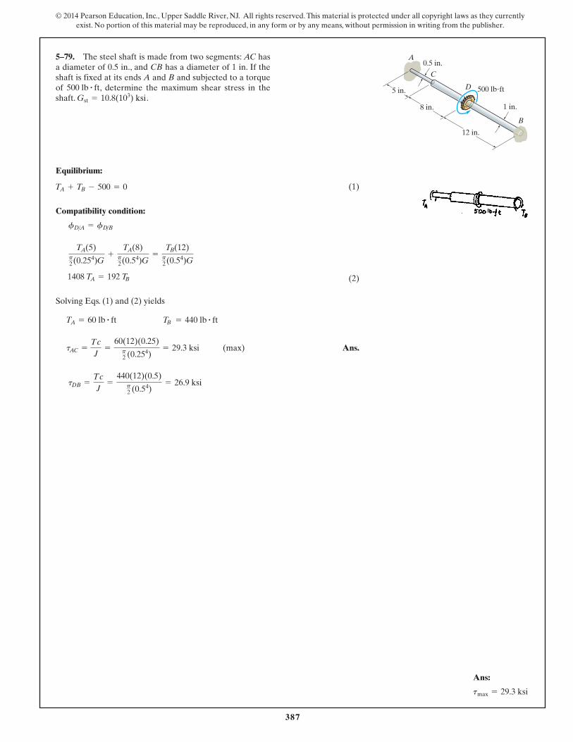
5–79. The steel shaft is made from two segments: AC hasa diameter of 0.5 in., and CB has a diameter of 1 in. If theshaft is fixed at its ends A and B and subjected to a torqueof , determine the maximum shear stress in theshaft. .Gst = 10.8(103) ksi
500 lb # ft
Equilibrium:
(1)
Compatibility condition:
(2)
Solving Eqs. (1) and (2) yields
(max) Ans.
tDB =
Tc
J=
440(12)(0.5)p2
(0.54)= 26.9 ksi
tAC =
Tc
J=
60(12)(0.25)p2
(0.254)= 29.3 ksi
TB = 440 lb # ftTA = 60 lb # ft
1408 TA = 192 TB
TA(5)p2(0.254)G
+
TA(8)p2(0.54)G
=
TB(12)p2(0.54)G
fD>A = fD>B
TA + TB - 500 = 0
5 in.
8 in.
12 in.
1 in.
0.5 in.A
B
C
D 500 lb�ft
Ans:
tmax = 29.3 ksi
Hibbeler_Chapter 5(375-438).qxd 2/7/13 7:55 PM Page 387
395
© 2014 Pearson Education, Inc., Upper Saddle River, NJ. All rights reserved. This material is protected under all copyright laws as they currentlyexist. No portion of this material may be reproduced, in any form or by any means, without permission in writing from the publisher.
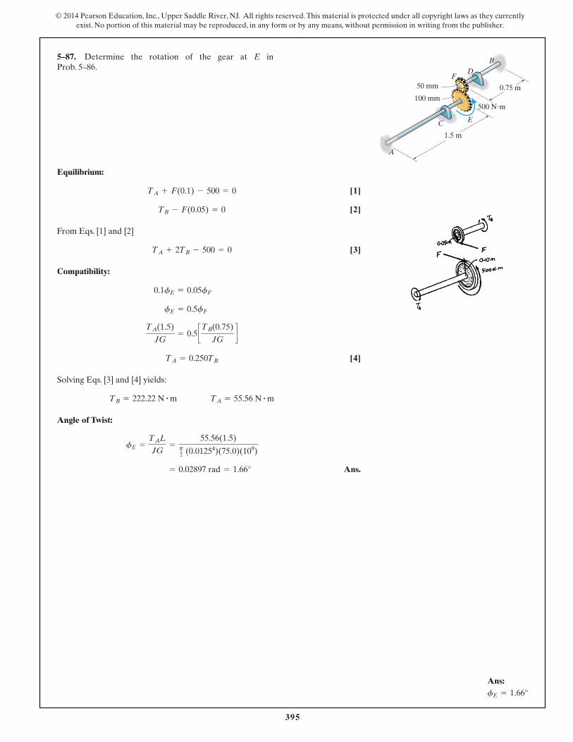
5–87. Determine the rotation of the gear at E in Prob. 5–86.
Equilibrium:
[1]
[2]
From Eqs. [1] and [2]
[3]
Compatibility:
[4]
Solving Eqs. [3] and [4] yields:
Angle of Twist:
Ans. = 0.02897 rad = 1.66°
fE =
TAL
JG=
55.56(1.5)p2 (0.01254)(75.0)(109)
TB = 222.22 N # m TA = 55.56 N # m
TA = 0.250TB
TA(1.5)
JG= 0.5 cTB(0.75)
JGd
fE = 0.5fF
0.1fE = 0.05fF
TA + 2TB - 500 = 0
TB - F(0.05) = 0
TA + F(0.1) - 500 = 0
B
50 mm
100 mm
A
C
D
1.5 m
0.75 m
500 N�m
F
E
Ans:fE = 1.66°
Hibbeler_Chapter 5(375-438).qxd 2/7/13 7:55 PM Page 395