15-447 computer architecturefall 2008 © october 6th, 2008 majd f. sakr [email protected]...
Post on 22-Dec-2015
218 views
TRANSCRIPT
15-447 Computer Architecture Fall 2008 ©
October 6th, 2008
Majd F. Sakr
www.qatar.cmu.edu/~msakr/15447-f08/
CS-447– Computer Architecture
Lecture 13Pipelining (1)
15-447 Computer Architecture Fall 2008 ©
Quiz
°Give an example of an instruction that would take longer to execute in a multi-cycle data path than in a single cycle data path. Explain why it takes longer.
°Give an example of an instruction that takes a shorter time to execute in a multi-cycle data path compared to a single cycled one. Explain why.
15-447 Computer Architecture Fall 2008 ©
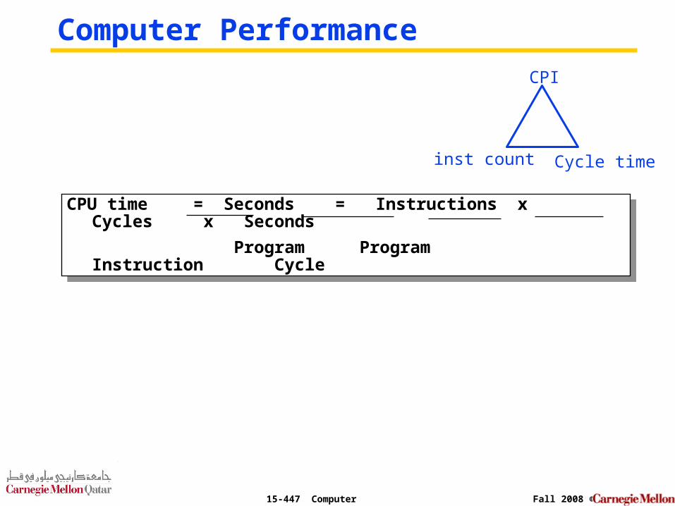
Computer Performance
CPU time = Seconds = Instructions x Cycles x Seconds
Program Program Instruction Cycle
CPU time = Seconds = Instructions x Cycles x Seconds
Program Program Instruction Cycle
inst count
CPI
Cycle time
15-447 Computer Architecture Fall 2008 ©
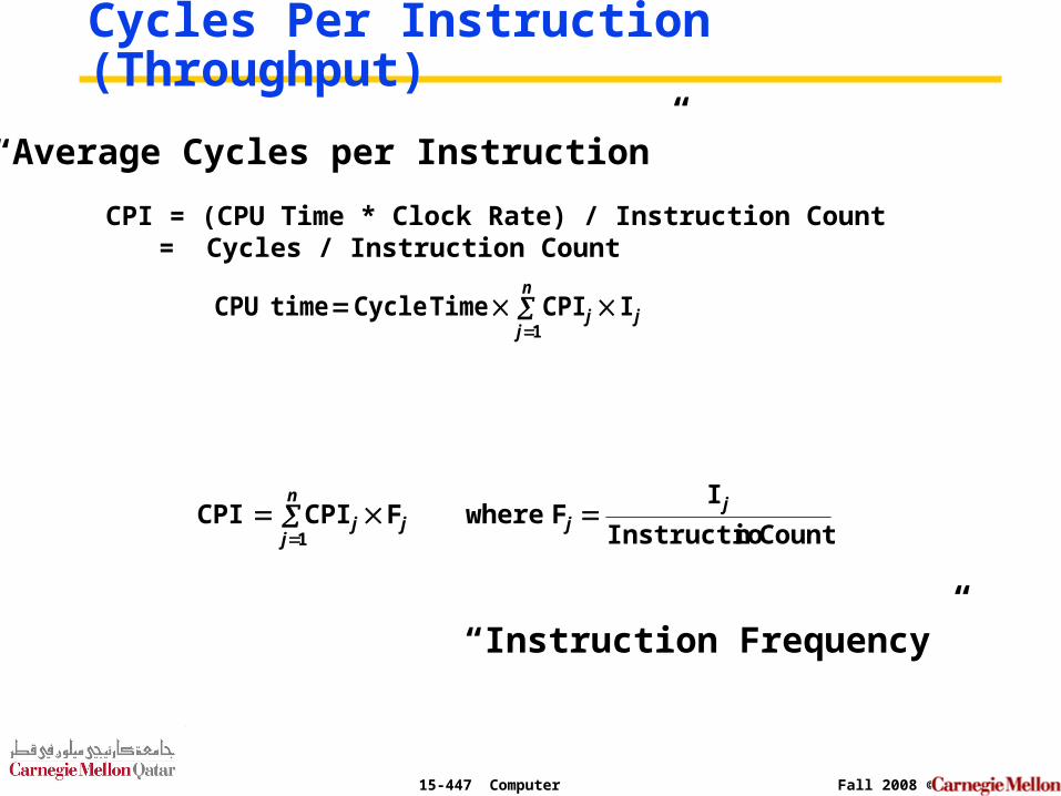
Cycles Per Instruction (Throughput)
“Instruction Frequency”
CPI = (CPU Time * Clock Rate) / Instruction Count = Cycles / Instruction Count
“Average Cycles per Instruction”
j
n
jj I CPI TimeCycle time CPU
1
Count nInstructio
I F where F CPI CPI j
j
n
jjj
1
15-447 Computer Architecture Fall 2008 ©
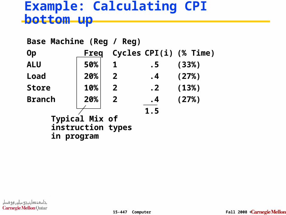
Example: Calculating CPI bottom up
Typical Mix of instruction typesin program
Base Machine (Reg / Reg)
Op Freq Cycles CPI(i) (% Time)
ALU 50% 1 .5 (33%)
Load 20% 2 .4 (27%)
Store 10% 2 .2 (13%)
Branch 20% 2 .4 (27%)
1.5
15-447 Computer Architecture Fall 2008 ©
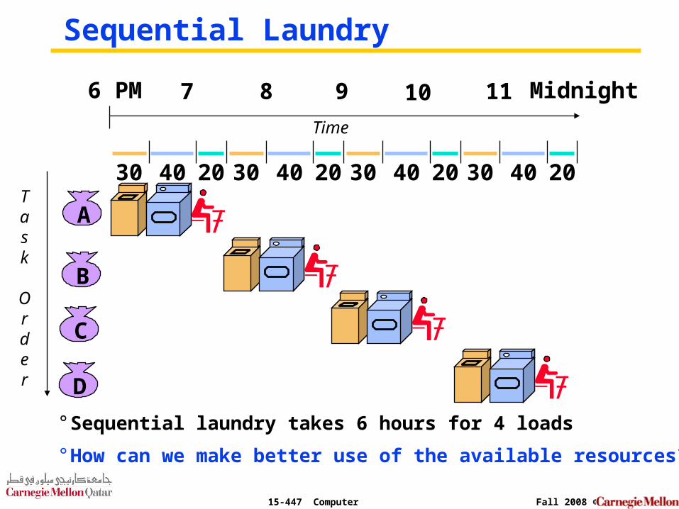
Sequential Laundry
° Sequential laundry takes 6 hours for 4 loads
° How can we make better use of the available resources?
A
B
C
D
30 40 2030 40 2030 40 2030 40 20
6 PM 7 8 9 10 11 Midnight
Task
Order
Time
15-447 Computer Architecture Fall 2008 ©
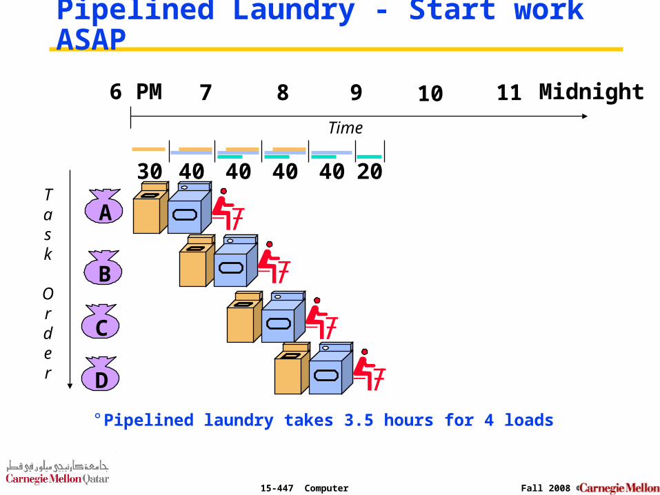
Pipelined Laundry - Start work ASAP
° Pipelined laundry takes 3.5 hours for 4 loads
A
B
C
D
6 PM 7 8 9 10 11 Midnight
Task
Order
Time
30 40 40 40 40 20
15-447 Computer Architecture Fall 2008 ©
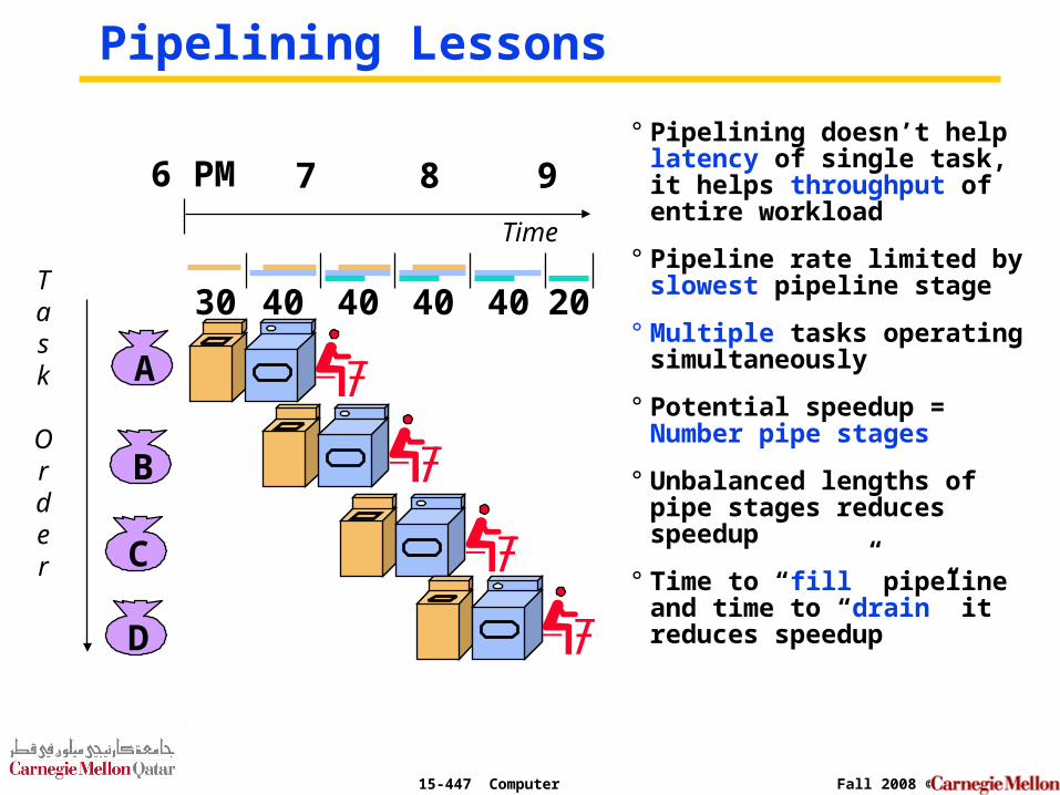
Pipelining Lessons
° Pipelining doesn’t help latency of single task, it helps throughput of entire workload
° Pipeline rate limited by slowest pipeline stage
° Multiple tasks operating simultaneously
° Potential speedup = Number pipe stages
° Unbalanced lengths of pipe stages reduces speedup
° Time to “fill” pipeline and time to “drain” it reduces speedup
A
B
C
D
6 PM 7 8 9
Task
Order
Time
30 40 40 40 40 20
15-447 Computer Architecture Fall 2008 ©
Pipelining
° Doesn’t improve latency!
° Execute billions of instructions, so throughput is what matters!
15-447 Computer Architecture Fall 2008 ©
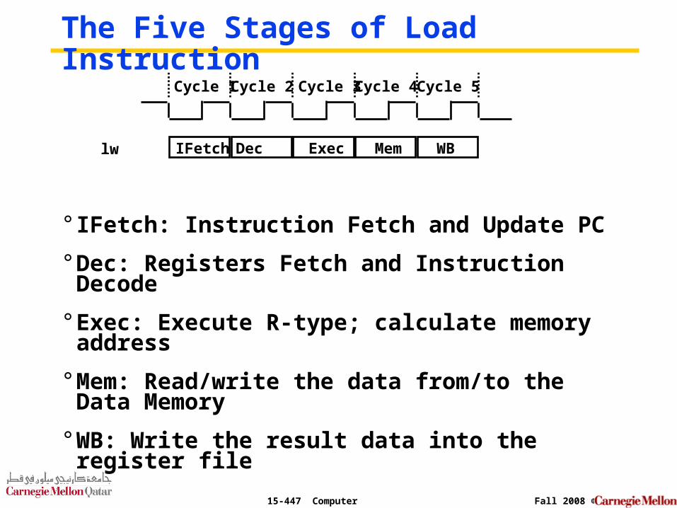
The Five Stages of Load Instruction
° IFetch: Instruction Fetch and Update PC
° Dec: Registers Fetch and Instruction Decode
° Exec: Execute R-type; calculate memory address
° Mem: Read/write the data from/to the Data Memory
° WB: Write the result data into the register file
Cycle 1 Cycle 2 Cycle 3 Cycle 4 Cycle 5
IFetch Dec Exec Mem WBlw
15-447 Computer Architecture Fall 2008 ©
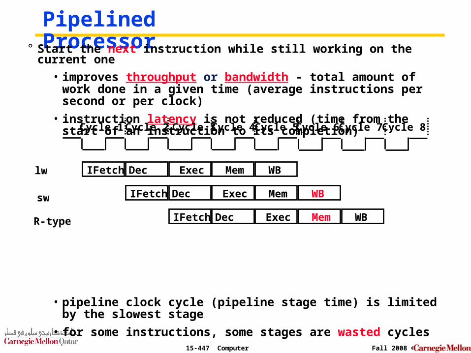
Pipelined Processor° Start the next instruction while still working on the current one
• improves throughput or bandwidth - total amount of work done in a given time (average instructions per second or per clock)
• instruction latency is not reduced (time from the start of an instruction to its completion)
• pipeline clock cycle (pipeline stage time) is limited by the slowest stage
• for some instructions, some stages are wasted cycles
Cycle 1 Cycle 2 Cycle 3 Cycle 4 Cycle 5
IFetch Dec Exec Mem WBlw
Cycle 7Cycle 6 Cycle 8
sw IFetch Dec Exec Mem WB
R-type IFetch Dec Exec Mem WB
15-447 Computer Architecture Fall 2008 ©
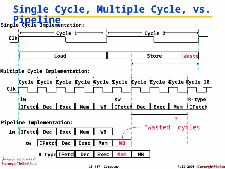
Single Cycle, Multiple Cycle, vs. Pipeline
ClkCycle 1
Multiple Cycle Implementation:
IFetch Dec Exec Mem WB
Cycle 2 Cycle 3 Cycle 4 Cycle 5 Cycle 6 Cycle 7 Cycle 8 Cycle 9Cycle 10
lw IFetch Dec Exec Mem WB
IFetch Dec Exec Mem
lw sw
Pipeline Implementation:
IFetch Dec Exec Mem WBsw
Clk
Single Cycle Implementation:
Load Store Waste
IFetch
R-type
IFetch Dec Exec Mem WBR-type
Cycle 1 Cycle 2
“wasted” cycles
15-447 Computer Architecture Fall 2008 ©
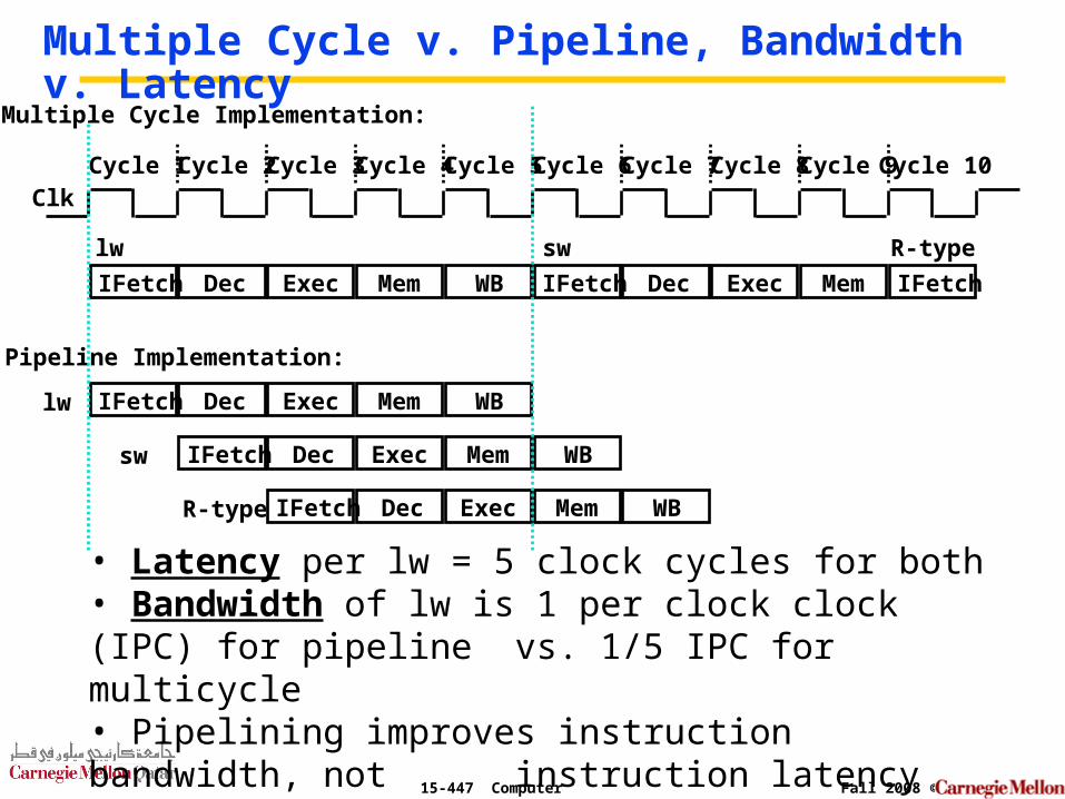
Multiple Cycle v. Pipeline, Bandwidth v. Latency
ClkCycle 1
Multiple Cycle Implementation:
IFetch Dec Exec Mem WB
Cycle 2 Cycle 3 Cycle 4 Cycle 5 Cycle 6 Cycle 7 Cycle 8 Cycle 9Cycle 10
lw IFetch Dec Exec Mem WB
IFetch Dec Exec Mem
lw sw
Pipeline Implementation:
IFetch Dec Exec Mem WBsw
IFetch
R-type
IFetch Dec Exec Mem WBR-type
• Latency per lw = 5 clock cycles for both• Bandwidth of lw is 1 per clock clock (IPC) for pipeline
vs. 1/5 IPC for multicycle• Pipelining improves instruction bandwidth, not instruction latency
15-447 Computer Architecture Fall 2008 ©
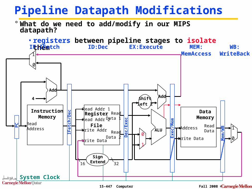
Pipeline Datapath Modifications
ReadAddress
InstructionMemory
Add
PC
4
0
1
Write Data
Read Addr 1
Read Addr 2
Write Addr
Register
File
Read Data 1
Read Data 2
16 32
ALU
1
0
Shiftleft 2
Add
DataMemory
Address
Write Data
ReadData
1
0
° What do we need to add/modify in our MIPS datapath?
• registers between pipeline stages to isolate them
IFe
tch
/De
c
De
c/E
xe
c
Ex
ec
/Me
m
Me
m/W
B
IF:IFetch ID:Dec EX:Execute MEM:MemAccess
WB:WriteBack
System Clock
SignExtend
15-447 Computer Architecture Fall 2008 ©
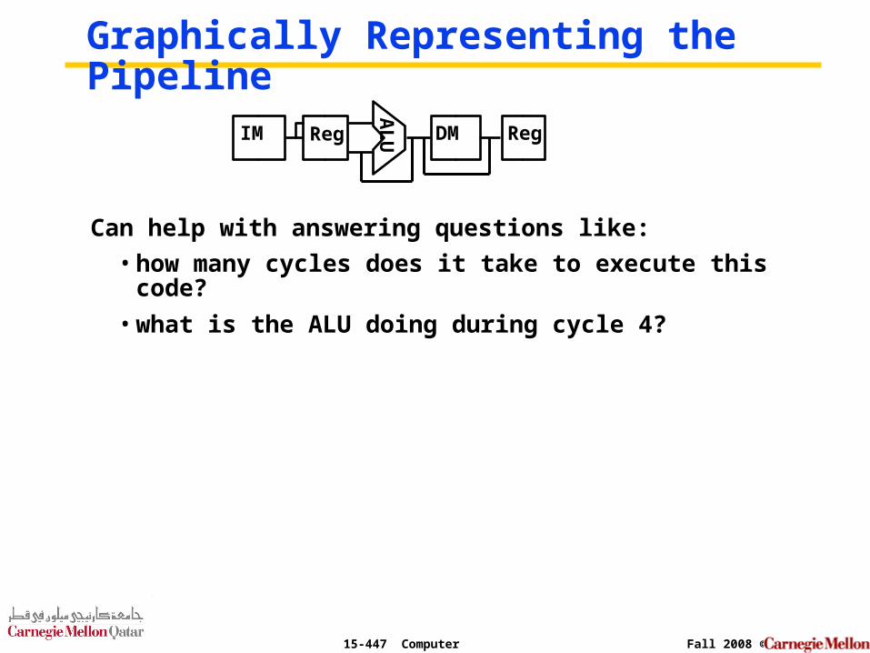
Graphically Representing the Pipeline
Can help with answering questions like:
• how many cycles does it take to execute this code?
• what is the ALU doing during cycle 4?
AL
UIM Reg DM Reg
15-447 Computer Architecture Fall 2008 ©
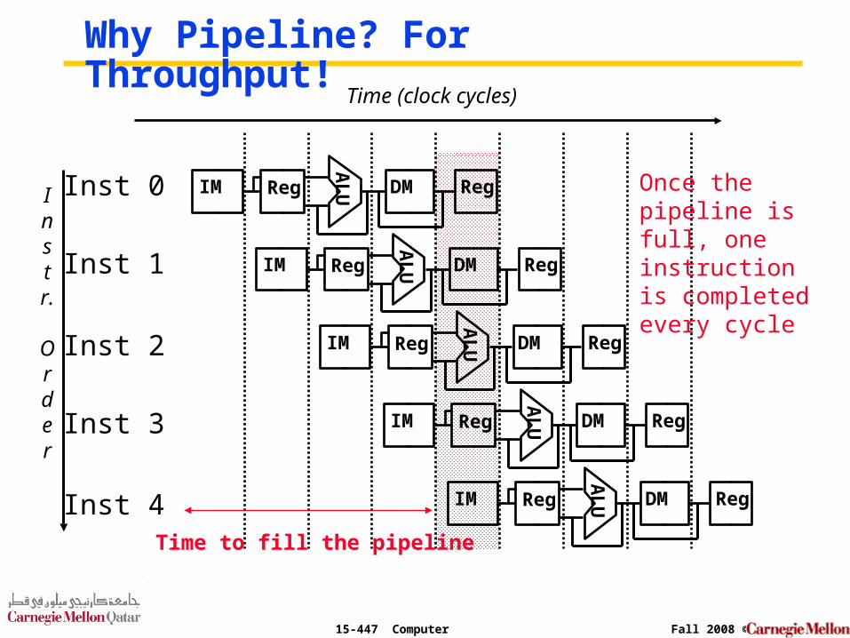
Why Pipeline? For Throughput!
Instr.
Order
Time (clock cycles)
Inst 0
Inst 1
Inst 2
Inst 4
Inst 3
AL
UIM Reg DM Reg
AL
UIM Reg DM Reg
AL
UIM Reg DM RegA
LUIM Reg DM Reg
AL
UIM Reg DM Reg
Once the pipeline is full, one instruction is completed every cycle
Time to fill the pipeline
15-447 Computer Architecture Fall 2008 ©
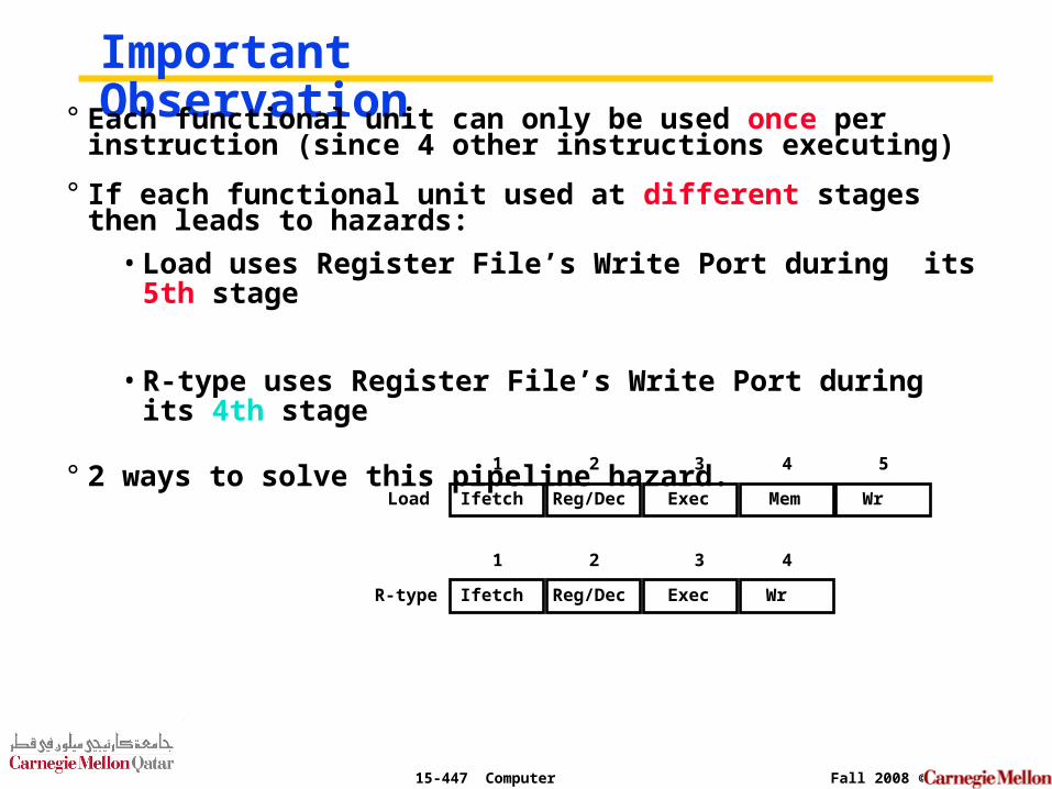
Important Observation° Each functional unit can only be used once per instruction
(since 4 other instructions executing)
° If each functional unit used at different stages then leads to hazards:
• Load uses Register File’s Write Port during its 5th stage
• R-type uses Register File’s Write Port during its 4th stage
° 2 ways to solve this pipeline hazard.
Ifetch Reg/Dec Exec Mem WrLoad
1 2 3 4 5
Ifetch Reg/Dec Exec WrR-type
1 2 3 4
15-447 Computer Architecture Fall 2008 ©
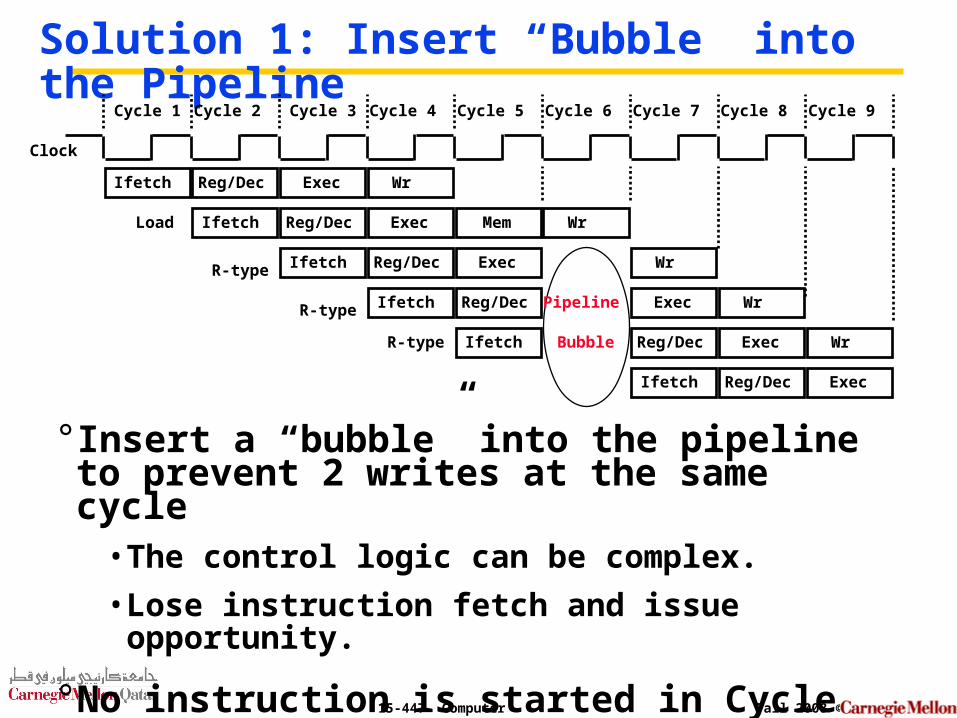
Solution 1: Insert “Bubble” into the Pipeline
° Insert a “bubble” into the pipeline to prevent 2 writes at the same cycle
• The control logic can be complex.
• Lose instruction fetch and issue opportunity.
° No instruction is started in Cycle 6!
Clock
Cycle 1 Cycle 2 Cycle 3 Cycle 4 Cycle 5 Cycle 6 Cycle 7 Cycle 8 Cycle 9
Ifetch Reg/Dec Exec WrR-type
Ifetch Reg/Dec Exec
Ifetch Reg/Dec Exec Mem WrLoad
Ifetch Reg/Dec Exec WrR-type
Ifetch Reg/Dec Exec WrR-type Pipeline
Bubble
Ifetch Reg/Dec Exec Wr
15-447 Computer Architecture Fall 2008 ©
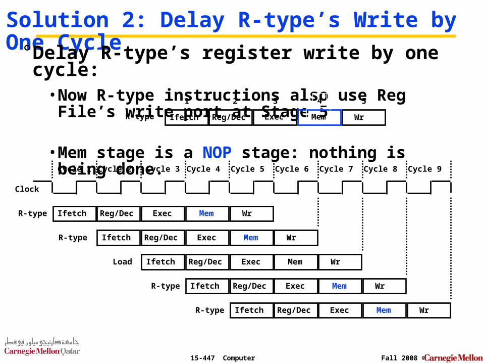
Solution 2: Delay R-type’s Write by One Cycle° Delay R-type’s register write by one cycle:
• Now R-type instructions also use Reg File’s write port at Stage 5
• Mem stage is a NOP stage: nothing is being done.
Clock
Cycle 1 Cycle 2 Cycle 3 Cycle 4 Cycle 5 Cycle 6 Cycle 7 Cycle 8 Cycle 9
Ifetch Reg/Dec Mem WrR-type
Ifetch Reg/Dec Mem WrR-type
Ifetch Reg/Dec Exec Mem WrLoad
Ifetch Reg/Dec Mem WrR-type
Ifetch Reg/Dec Mem WrR-type
Ifetch Reg/Dec Exec WrR-type Mem
Exec
Exec
Exec
Exec
1 2 3 4 5
15-447 Computer Architecture Fall 2008 ©
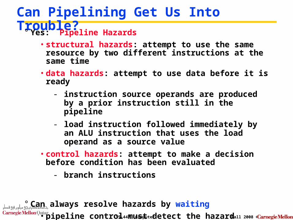
Can Pipelining Get Us Into Trouble?
° Yes: Pipeline Hazards
• structural hazards: attempt to use the same resource by two different instructions at the same time
• data hazards: attempt to use data before it is ready
- instruction source operands are produced by a prior instruction still in the pipeline
- load instruction followed immediately by an ALU instruction that uses the load operand as a source value
• control hazards: attempt to make a decision before condition has been evaluated
- branch instructions
° Can always resolve hazards by waiting
• pipeline control must detect the hazard
• take action (or delay action) to resolve hazards
15-447 Computer Architecture Fall 2008 ©
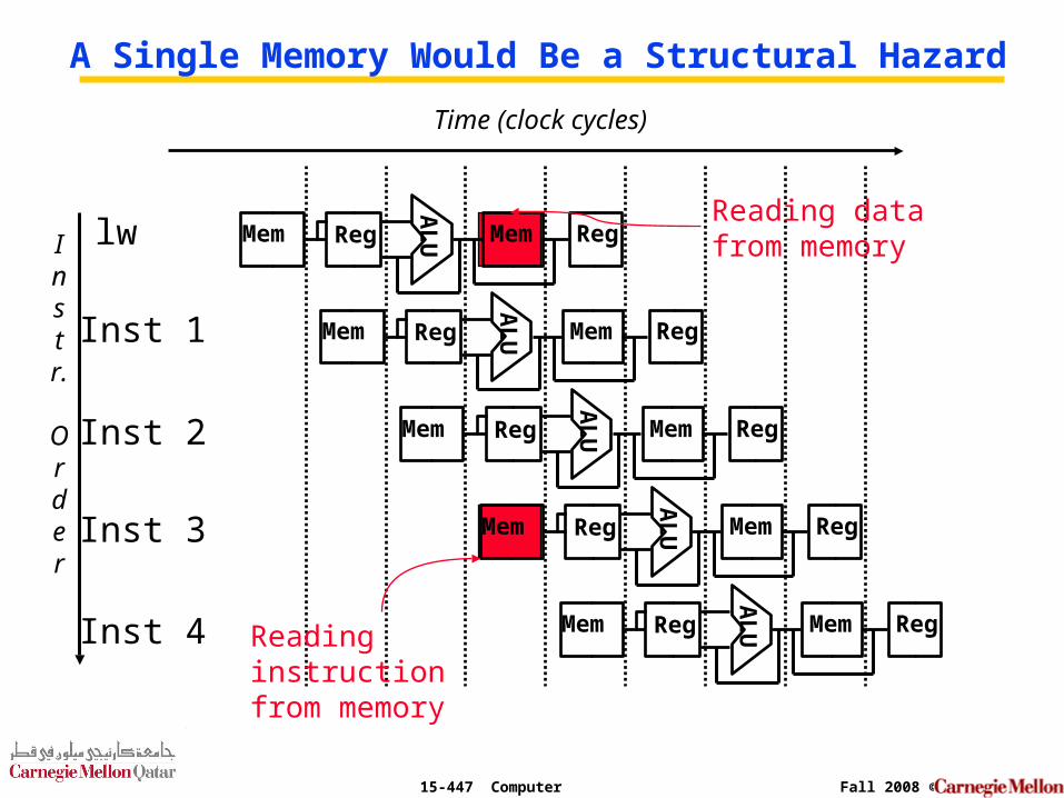
Instr.
Order
Time (clock cycles)
lw
Inst 1
Inst 2
Inst 4
Inst 3
AL
UMem Reg Mem Reg
AL
UMem Reg Mem Reg
AL
UMem Reg Mem RegA
LUMem Reg Mem Reg
AL
UMem Reg Mem Reg
A Single Memory Would Be a Structural Hazard
Reading data from memory
Reading instruction from memory
15-447 Computer Architecture Fall 2008 ©
Summary
° All modern day processors use pipelining
° Pipelining doesn’t help latency of single task, it helps throughput of entire workload
• Multiple tasks operating simultaneously using different resources
° Potential speedup = Number of pipe stages
° Pipeline rate limited by slowest pipeline stage
• Unbalanced lengths of pipe stages reduces speedup
• Time to “fill” pipeline and time to “drain” it reduces speedup
° Must detect and resolve hazards
• Stalling negatively affects throughput