15-441 computer networking lecture 5 - coding and error control 15-441 © cmu 2010
Post on 21-Dec-2015
229 views
TRANSCRIPT
15-441 Computer Networking
Lecture 5 - Coding and Error Control
15-441 © CMU 2010

From Signals to Packets
Analog Signal
“Digital” Signal
Bit Stream 0 0 1 0 1 1 1 0 0 0 1
Packets0100010101011100101010101011101110000001111010101110101010101101011010111001
Header/Body Header/Body Header/Body
ReceiverSenderPacket
Transmission
215-441 © CMU 2010
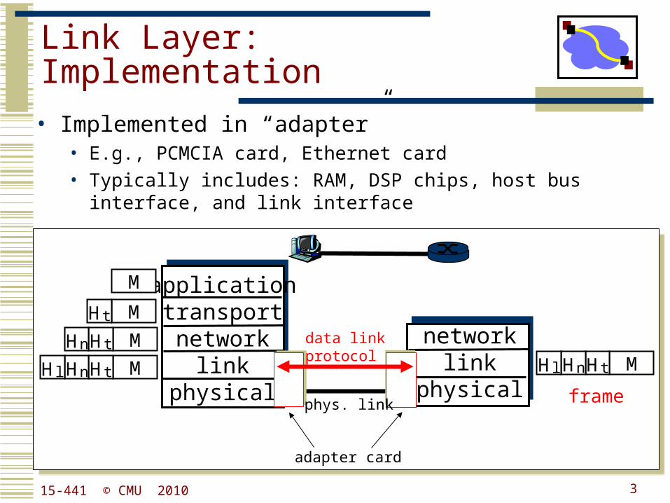
Link Layer: Implementation
• Implemented in “adapter” • E.g., PCMCIA card, Ethernet card • Typically includes: RAM, DSP chips, host bus interface, and link
interface
applicationtransportnetwork
linkphysical
networklink
physical
M
M
M
M
Ht
HtHn
HtHnHl MHtHnHl
framephys. link
data linkprotocol
adapter card
315-441 © CMU 2010
Outline
• Encoding• Digital signal to bits
• Framing• Bit stream to packets
• Packet loss & corruption• Error detection• Flow control• Loss recovery
515-441 © CMU 2010
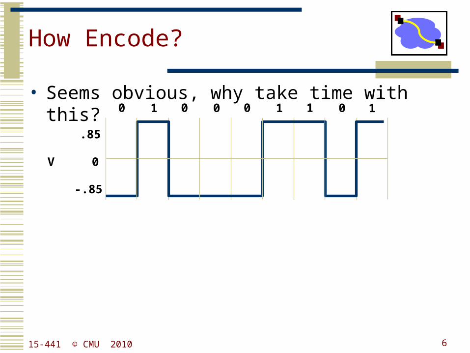
How Encode?
• Seems obvious, why take time with this?
V 0
.85
-.85
0 0 0 11 0 1 0 1
615-441 © CMU 2010
Why Do We Need Encoding?
• Keep receiver synchronized with sender.• Create control symbols, in addition to regular data
symbols.• E.g. start or end of frame, escape, ...
• Error detection or error corrections.• Some codes are illegal so receiver can detect certain
classes of errors• Minor errors can be corrected by having multiple adjacent
signals mapped to the same data symbol
• Encoding can be done one bit at a time or in multi-bit blocks, e.g., 4 or 8 bits.
• Encoding can be very complex, e.g. wireless.
815-441 © CMU 2010
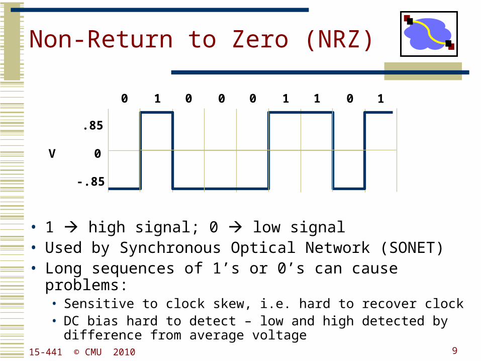
Non-Return to Zero (NRZ)
• 1 high signal; 0 low signal• Used by Synchronous Optical Network (SONET)• Long sequences of 1’s or 0’s can cause problems:
• Sensitive to clock skew, i.e. hard to recover clock• DC bias hard to detect – low and high detected by difference
from average voltage
V 0
.85
-.85
0 0 0 11 0 1 0 1
915-441 © CMU 2010
Clock Recovery
• When to sample voltage?• Synchronized sender and receiver clocks• Need easily detectible event at both ends
• Signal transitions help resync sender and receiver• Need frequent transitions to prevent clock skew• SONET XOR’s bit sequence to ensure frequent
transitions
1015-441 © CMU 2010

Non-Return to Zero Inverted (NRZI)
• 1 make transition; 0 signal stays the same• Solves the problem for long sequences of 1’s, but
not for 0’s.
V 0
.85
-.85
0 0 0 11 0 1 0 1
1115-441 © CMU 2010
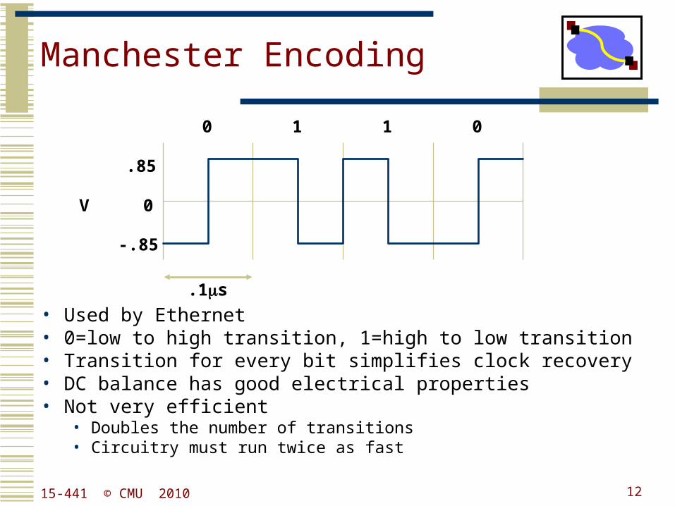
Manchester Encoding
• Used by Ethernet• 0=low to high transition, 1=high to low transition• Transition for every bit simplifies clock recovery• DC balance has good electrical properties• Not very efficient
• Doubles the number of transitions• Circuitry must run twice as fast
V 0
.85
-.85
0 1 1 0
.1s
1215-441 © CMU 2010
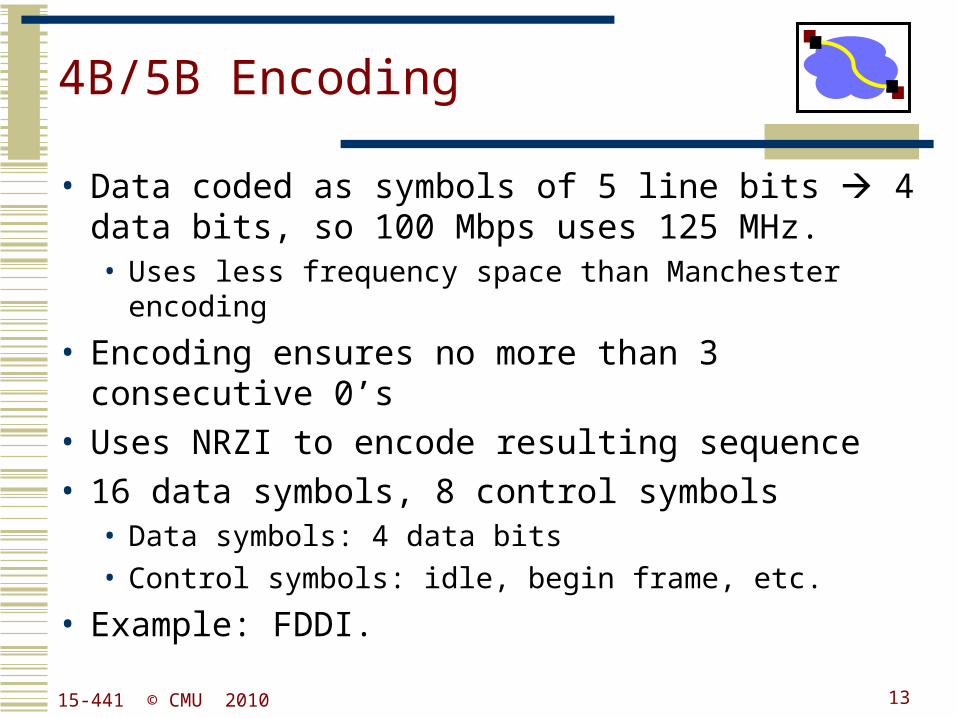
4B/5B Encoding
• Data coded as symbols of 5 line bits 4 data bits, so 100 Mbps uses 125 MHz.• Uses less frequency space than Manchester encoding
• Encoding ensures no more than 3 consecutive 0’s• Uses NRZI to encode resulting sequence• 16 data symbols, 8 control symbols
• Data symbols: 4 data bits• Control symbols: idle, begin frame, etc.
• Example: FDDI.
1315-441 © CMU 2010
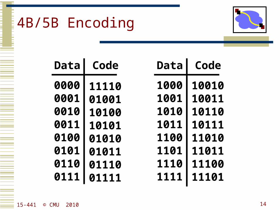
4B/5B Encoding
00000001001000110100010101100111
1111001001101001010101010010110111001111
Data Code
10001001101010111100110111101111
1001010011101101011111010110111110011101
Data Code
1415-441 © CMU 2010
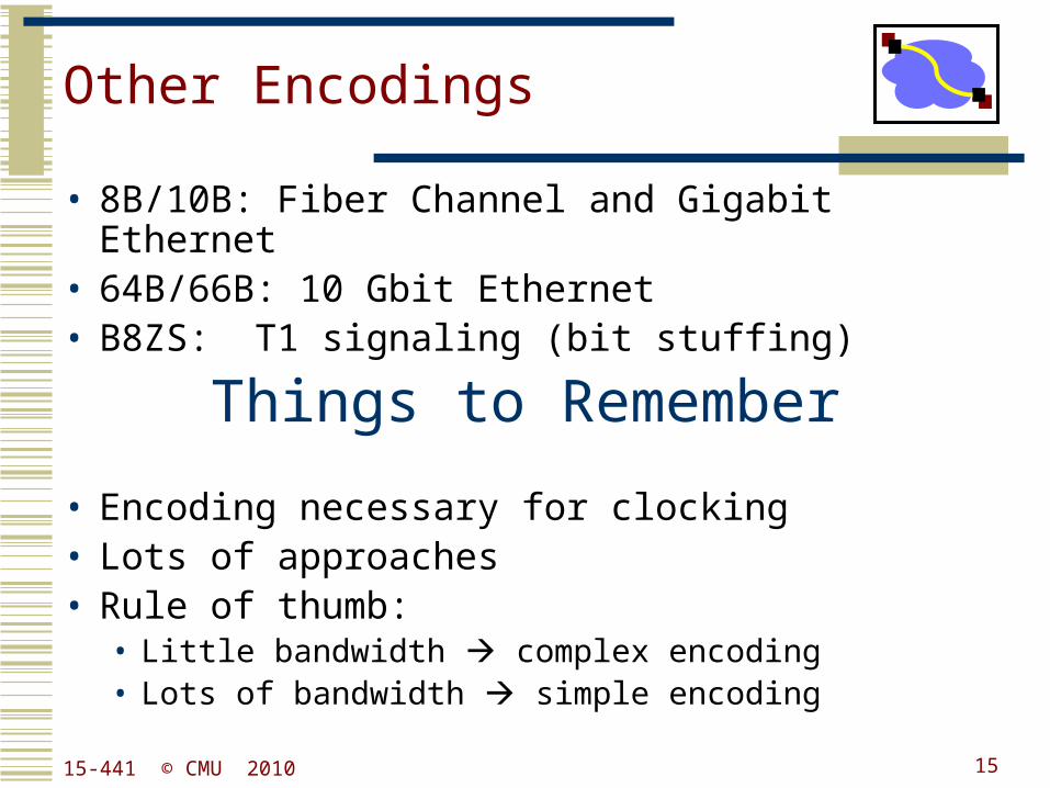
Other Encodings
• 8B/10B: Fiber Channel and Gigabit Ethernet• 64B/66B: 10 Gbit Ethernet• B8ZS: T1 signaling (bit stuffing)
• Encoding necessary for clocking• Lots of approaches• Rule of thumb:
• Little bandwidth complex encoding• Lots of bandwidth simple encoding
Things to Remember
1515-441 © CMU 2010
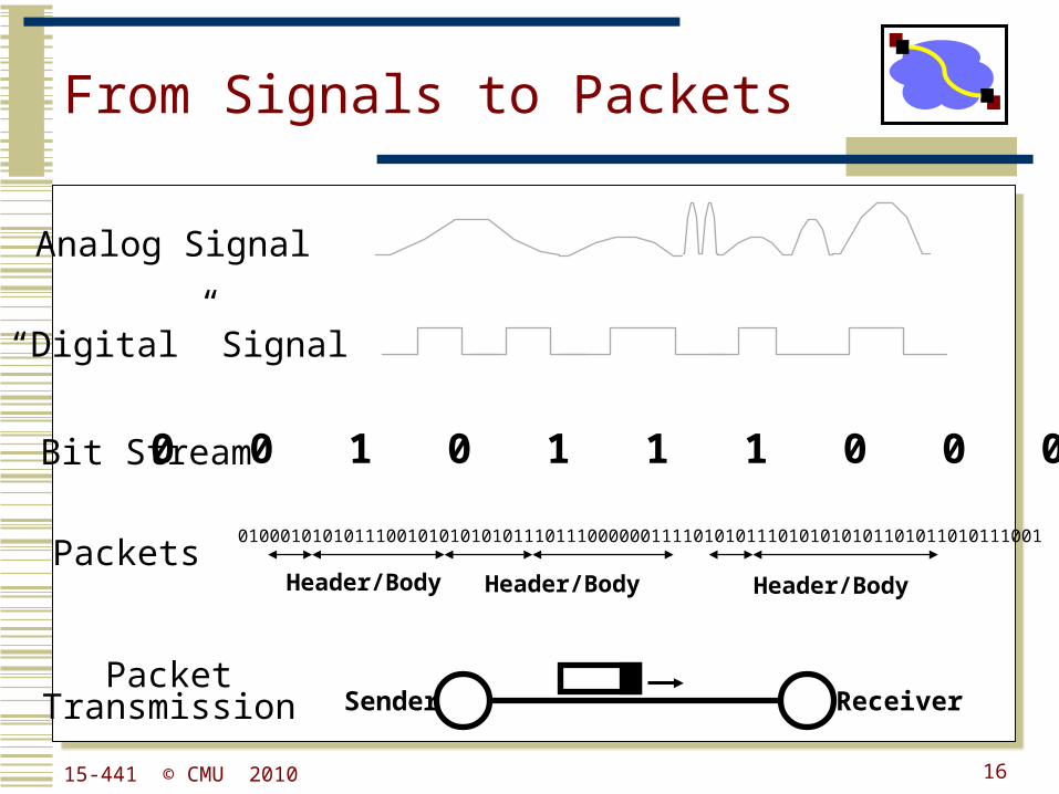
From Signals to Packets
Analog Signal
“Digital” Signal
Bit Stream 0 0 1 0 1 1 1 0 0 0 1
Packets0100010101011100101010101011101110000001111010101110101010101101011010111001
Header/Body Header/Body Header/Body
ReceiverSenderPacket
Transmission
1615-441 © CMU 2010
Outline
• Encoding• Digital signal to bits
• Framing• Bit stream to packets
• Packet loss & corruption• Error detection• Flow control• Loss recovery
1715-441 © CMU 2010
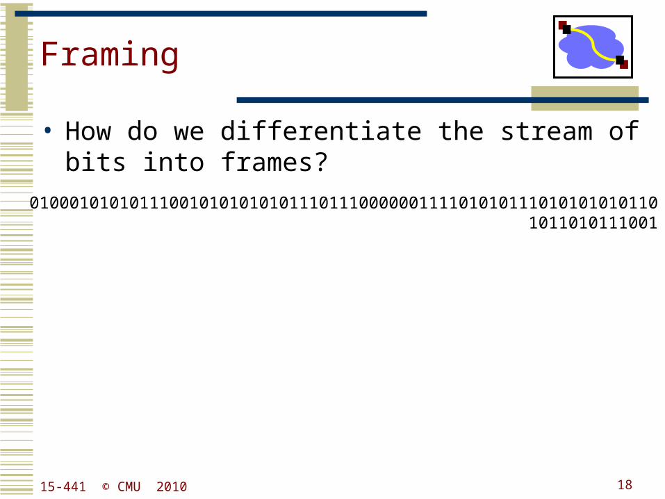
Framing
• How do we differentiate the stream of bits into frames?
0100010101011100101010101011101110000001111010101110101010101101011010111001
1815-441 © CMU 2010
Framing
• A link layer function, defining which bits have which function.
• Minimal functionality: mark the beginning and end of packets (or frames).
• Some techniques:• out of band delimiters (e.g. FDDI 4B/5B control
symbols)• frame delimiter characters with character stuffing• frame delimiter codes with bit stuffing• synchronous transmission (e.g. SONET)
1915-441 © CMU 2010
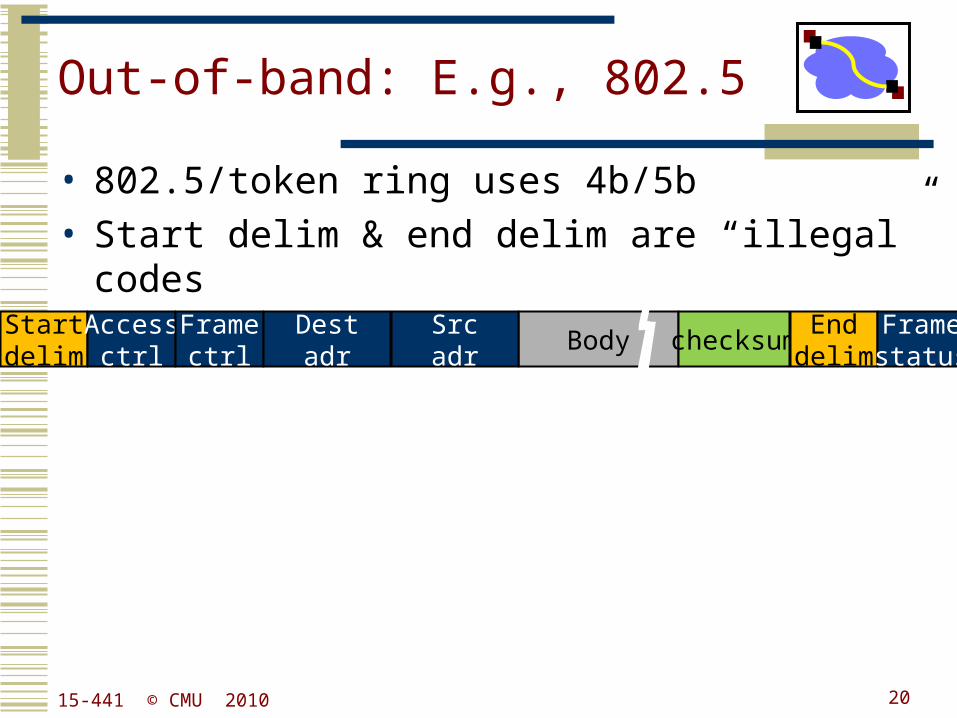
Out-of-band: E.g., 802.5
• 802.5/token ring uses 4b/5b• Start delim & end delim are “illegal” codes
Startdelim
Accessctrl Body checksumFrame
ctrlDestadr
Srcadr
Enddelim
Framestatus
2015-441 © CMU 2010
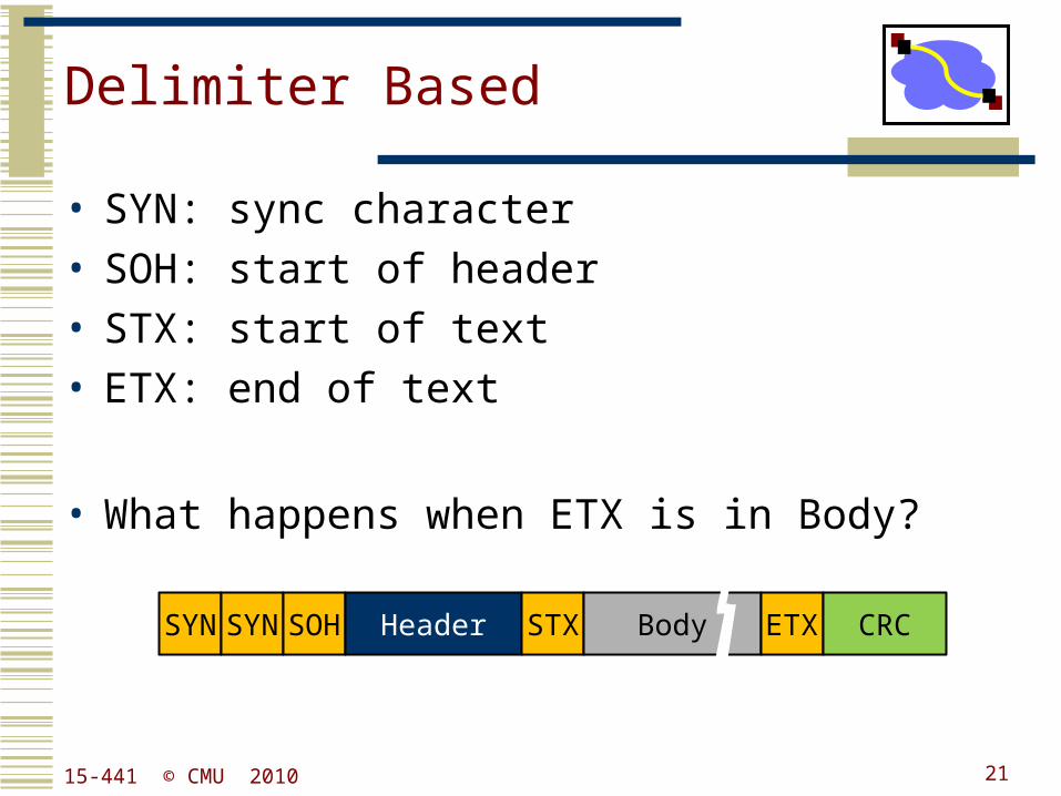
Delimiter Based
• SYN: sync character• SOH: start of header• STX: start of text• ETX: end of text
• What happens when ETX is in Body?
SYN SYN SOH Header STX Body ETX CRC
2115-441 © CMU 2010
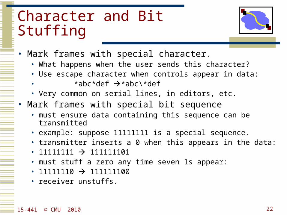
Character and Bit Stuffing
• Mark frames with special character.• What happens when the user sends this character?• Use escape character when controls appear in data:• *abc*def *abc\*def• Very common on serial lines, in editors, etc.
• Mark frames with special bit sequence• must ensure data containing this sequence can be transmitted• example: suppose 11111111 is a special sequence.• transmitter inserts a 0 when this appears in the data:• 11111111 111111101• must stuff a zero any time seven 1s appear:• 11111110 111111100• receiver unstuffs.
2215-441 © CMU 2010
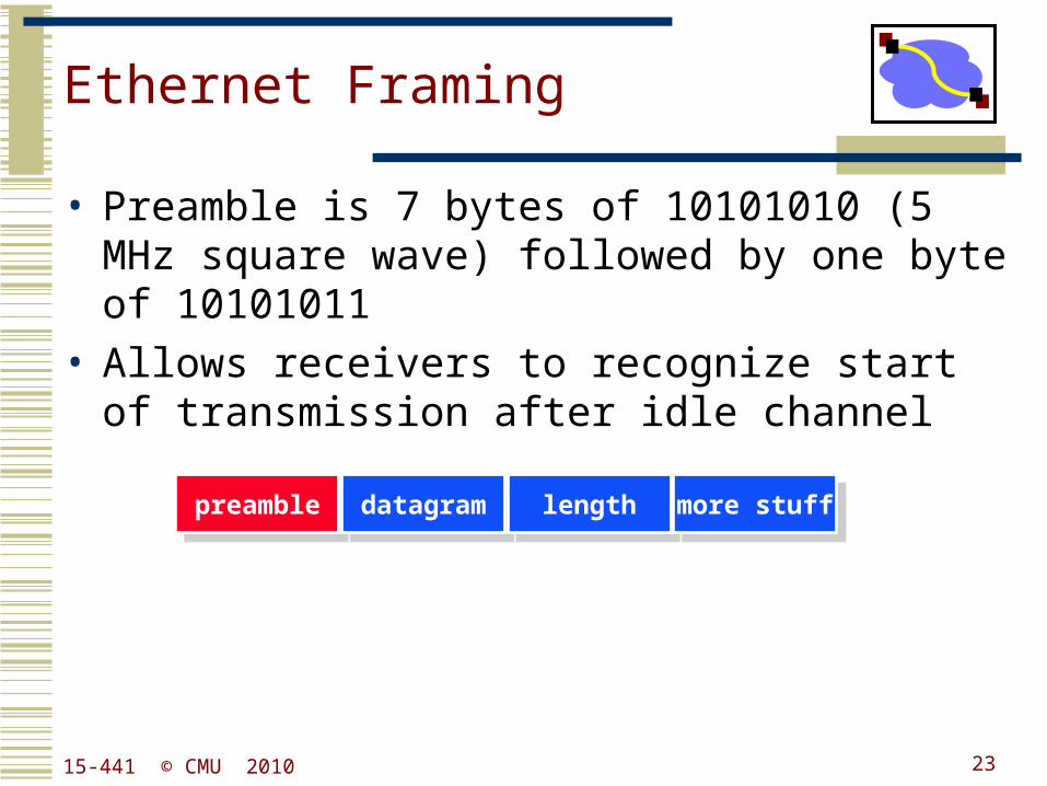
Ethernet Framing
• Preamble is 7 bytes of 10101010 (5 MHz square wave) followed by one byte of 10101011
• Allows receivers to recognize start of transmission after idle channel
preamblepreamble datagramdatagram lengthlength more stuffmore stuff
2315-441 © CMU 2010
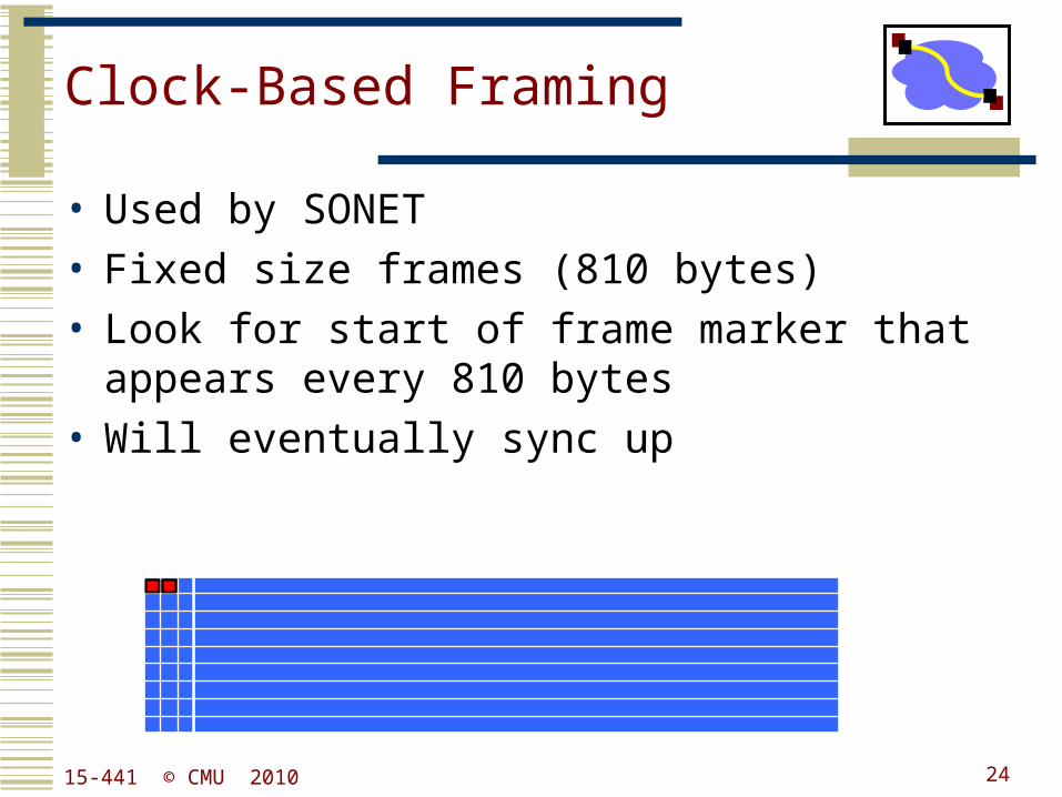
Clock-Based Framing
• Used by SONET• Fixed size frames (810 bytes)• Look for start of frame marker that appears every
810 bytes• Will eventually sync up
2415-441 © CMU 2010
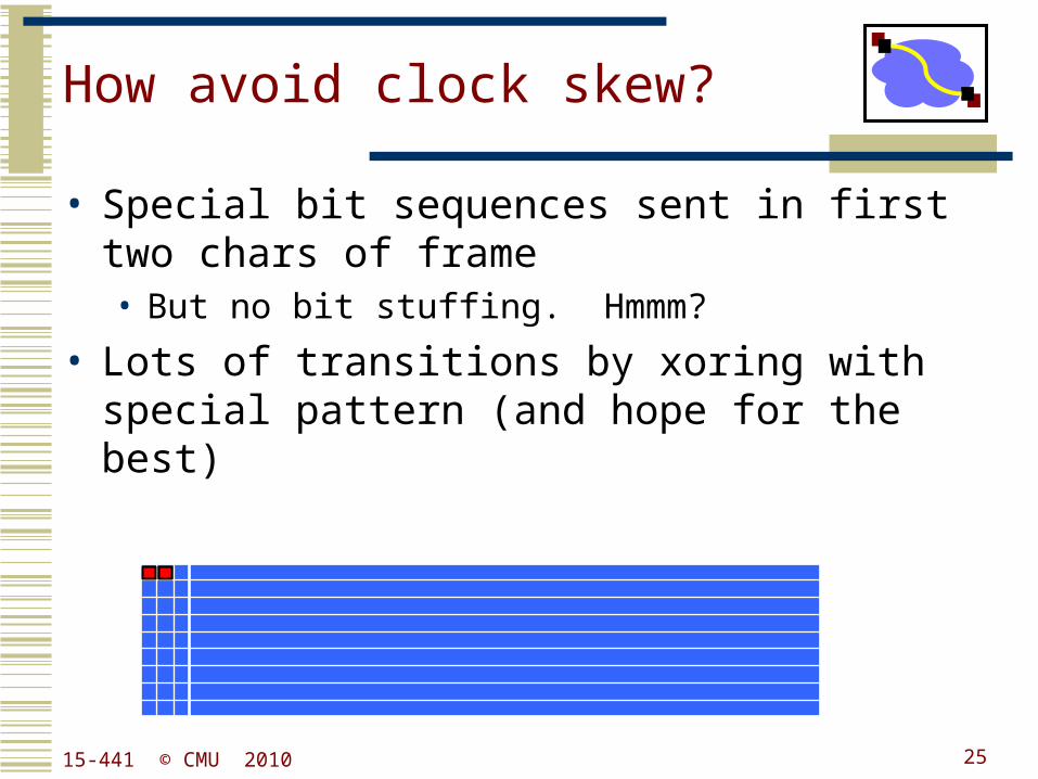
How avoid clock skew?
• Special bit sequences sent in first two chars of frame• But no bit stuffing. Hmmm?
• Lots of transitions by xoring with special pattern (and hope for the best)
2515-441 © CMU 2010
Outline
• Encoding• Digital signal to bits
• Framing• Bit stream to packets
• Packet loss & corruption• Error detection• Flow control• Loss recovery
2615-441 © CMU 2010
Error Coding
• Transmission process may introduce errors into a message.• Single bit errors versus burst errors
• Detection:• Requires a convention that some messages are invalid• Hence requires extra bits• An (n,k) code has codewords of n bits with k data bits and r
= (n-k) redundant check bits
• Correction• Forward error correction: many related code words map to
the same data word• Detect errors and retry transmission
2715-441 © CMU 2010
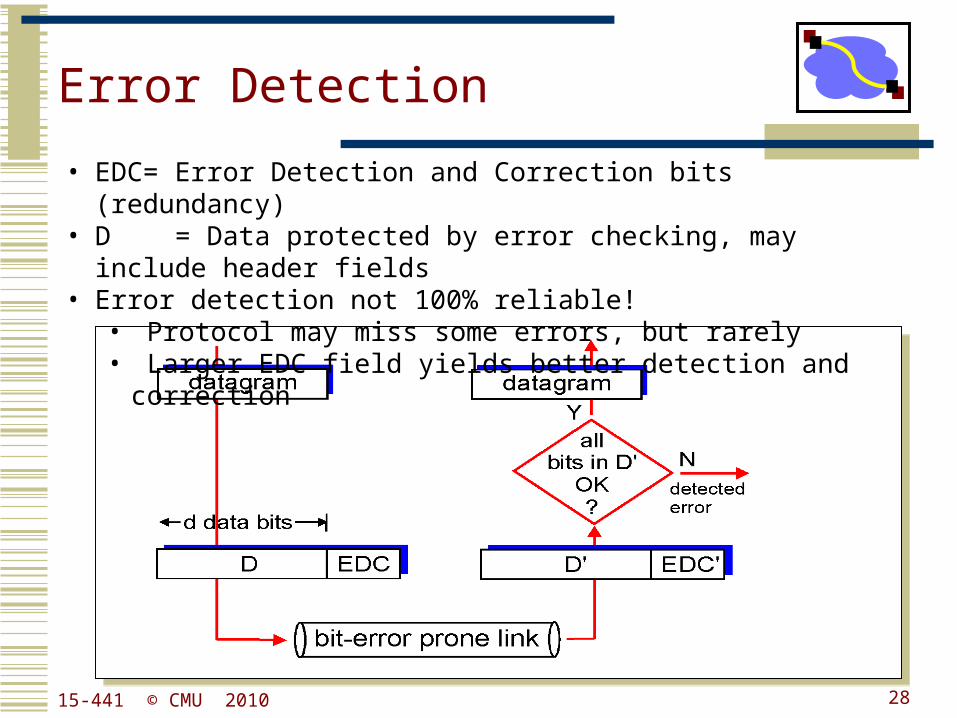
Error Detection
• EDC= Error Detection and Correction bits (redundancy)• D = Data protected by error checking, may include header fields • Error detection not 100% reliable!
• Protocol may miss some errors, but rarely• Larger EDC field yields better detection and correction
2815-441 © CMU 2010
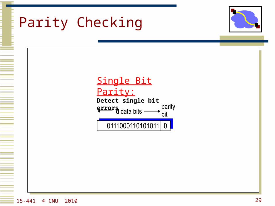
Parity Checking
Single Bit Parity:Detect single bit errors
2915-441 © CMU 2010
30
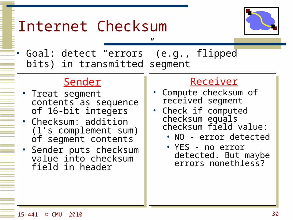
Internet Checksum
Sender• Treat segment contents
as sequence of 16-bit integers
• Checksum: addition (1’s complement sum) of segment contents
• Sender puts checksum value into checksum field in header
Receiver• Compute checksum of
received segment• Check if computed
checksum equals checksum field value:• NO - error detected• YES - no error detected.
But maybe errors nonethless?
• Goal: detect “errors” (e.g., flipped bits) in transmitted segment
15-441 © CMU 2010
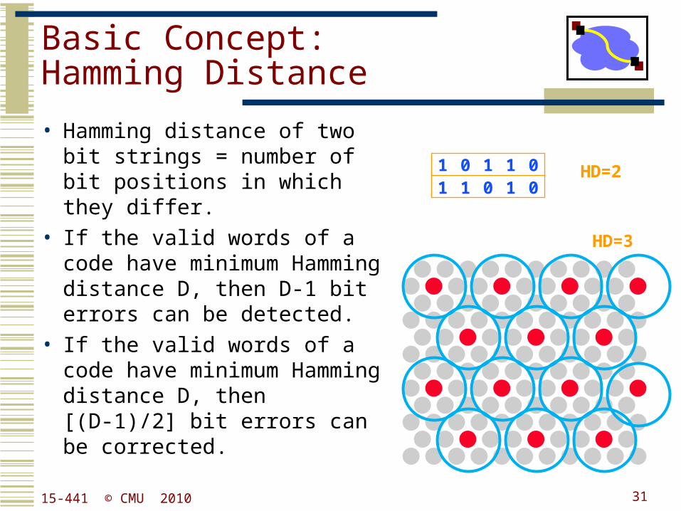
Basic Concept:Hamming Distance
• Hamming distance of two bit strings = number of bit positions in which they differ.
• If the valid words of a code have minimum Hamming distance D, then D-1 bit errors can be detected.
• If the valid words of a code have minimum Hamming distance D, then [(D-1)/2] bit errors can be corrected.
1 0 1 1 01 1 0 1 0
HD=2
HD=3
3115-441 © CMU 2010
Cyclic Redundancy Codes(CRC)
• Commonly used codes that have good error detection properties.• Can catch many error combinations with a small
number of redundant bits
• Based on division of polynomials.• Errors can be viewed as adding terms to the polynomial• Should be unlikely that the division will still work
• Can be implemented very efficiently in hardware.• Examples:
• CRC-32: Ethernet• CRC-8, CRC-10, CRC-32: ATM
3315-441 © CMU 2010
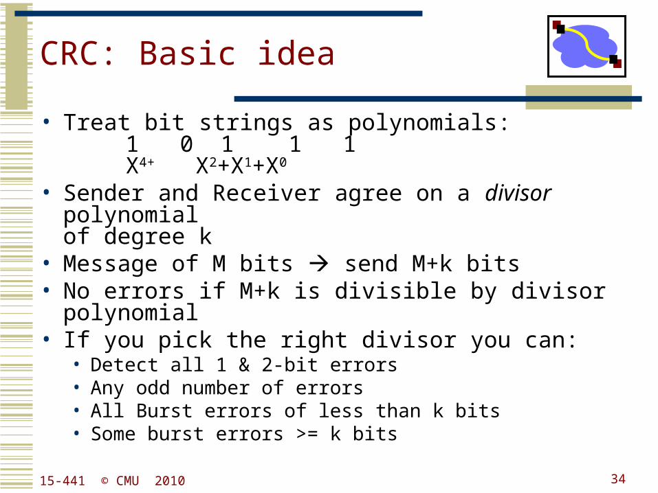
CRC: Basic idea
• Treat bit strings as polynomials:1 0 1 1 1X4+ X2+X1+X0
• Sender and Receiver agree on a divisor polynomialof degree k
• Message of M bits send M+k bits• No errors if M+k is divisible by divisor polynomial• If you pick the right divisor you can:
• Detect all 1 & 2-bit errors• Any odd number of errors• All Burst errors of less than k bits• Some burst errors >= k bits
3415-441 © CMU 2010
Outline
• Encoding• Digital signal to bits
• Framing• Bit stream to packets
• Packet loss & corruption• Error detection• Flow control• Loss recovery
3515-441 © CMU 2010
Link Flow Control and Error Recovery
• Dealing with receiver overflow: flow control.
• Dealing with packet loss and corruption: error control.
• Meta-comment: these issues are relevant at many layers.• Link layer: sender and receiver attached to the same “wire”
• End-to-end: transmission control protocol (TCP) - sender and receiver are the end points of a connection
• How can we implement flow control?• “You may send” (windows, stop-and-wait, etc.)
• “Please shut up” (source quench, 802.3x pause frames, etc.)
• Where are each of these appropriate?
15-441 © CMU 2010 36
A Naïve Protocol
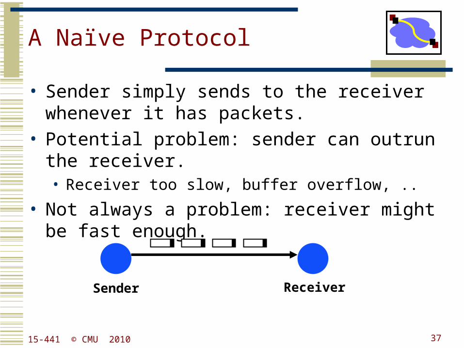
• Sender simply sends to the receiver whenever it has packets.
• Potential problem: sender can outrun the receiver.• Receiver too slow, buffer overflow, ..
• Not always a problem: receiver might be fast enough.
Sender Receiver
3715-441 © CMU 2010
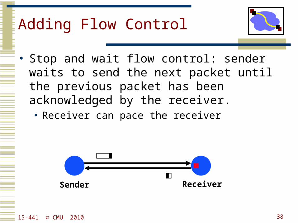
Adding Flow Control
• Stop and wait flow control: sender waits to send the next packet until the previous packet has been acknowledged by the receiver.• Receiver can pace the receiver
Sender Receiver
3815-441 © CMU 2010
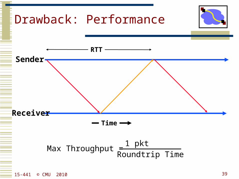
Drawback: Performance
Sender
ReceiverTime
Max Throughput = 1 pkt
Roundtrip Time
RTT
3915-441 © CMU 2010
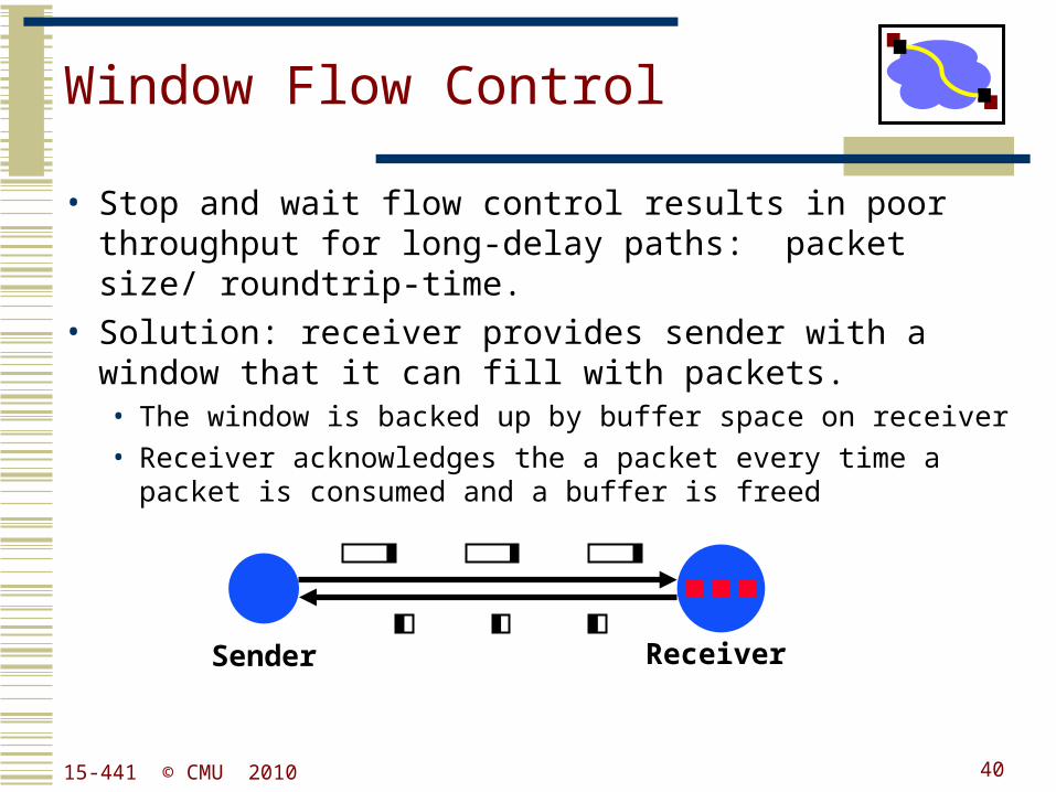
Window Flow Control
• Stop and wait flow control results in poor throughput for long-delay paths: packet size/ roundtrip-time.
• Solution: receiver provides sender with a window that it can fill with packets.• The window is backed up by buffer space on receiver
• Receiver acknowledges the a packet every time a packet is consumed and a buffer is freed
Sender Receiver
4015-441 © CMU 2010
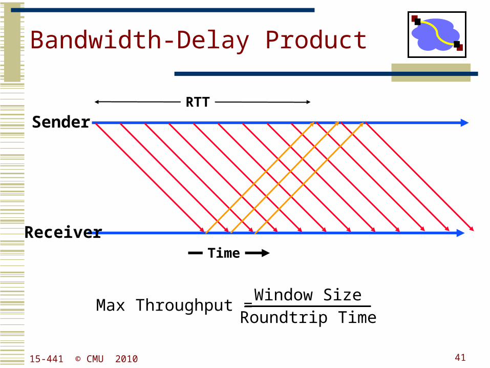
Bandwidth-Delay Product
Sender
ReceiverTime
Max Throughput = Window Size
Roundtrip Time
RTT
4115-441 © CMU 2010
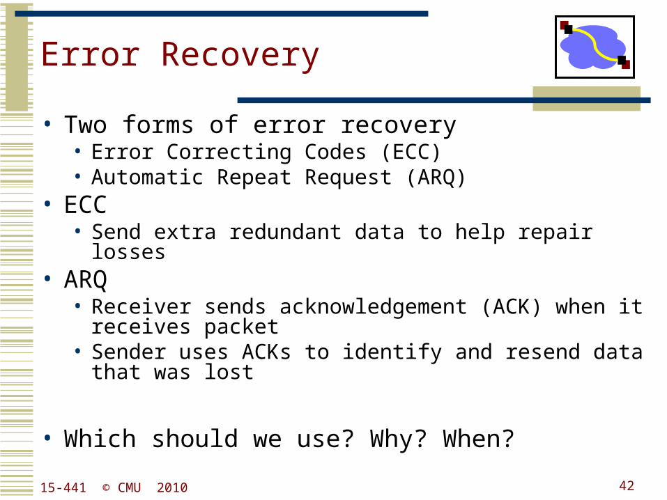
Error Recovery
• Two forms of error recovery• Error Correcting Codes (ECC)• Automatic Repeat Request (ARQ)
• ECC• Send extra redundant data to help repair losses
• ARQ• Receiver sends acknowledgement (ACK) when it
receives packet• Sender uses ACKs to identify and resend data that was
lost
• Which should we use? Why? When?
4215-441 © CMU 2010
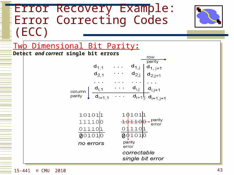
Error Recovery Example:Error Correcting Codes (ECC)
Two Dimensional Bit Parity:Detect and correct single bit errors
0 0
4315-441 © CMU 2010
44
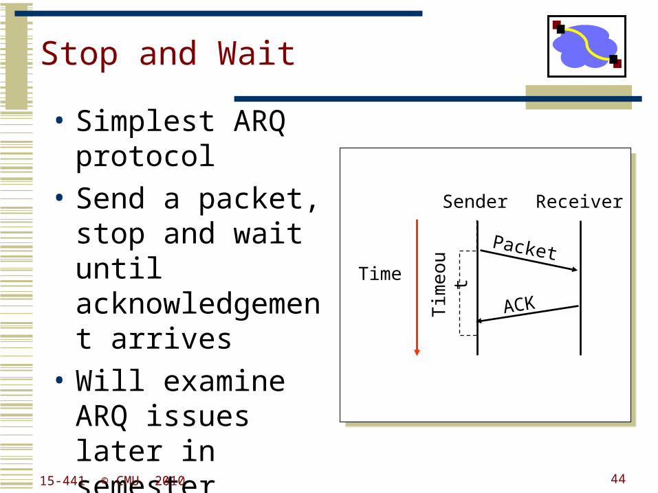
Stop and Wait
Time
Packet
ACKTim
eou
t
• Simplest ARQ protocol
• Send a packet, stop and wait until acknowledgement arrives
• Will examine ARQ issues later in semester
Sender Receiver
15-441 © CMU 2010
45
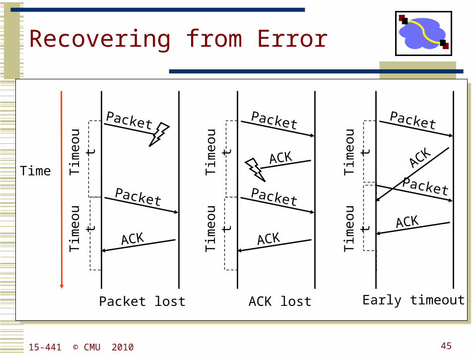
Recovering from Error
Packet
ACK
Tim
eou
t
Packet
Tim
eou
t
Time
Packet
ACK
Tim
eou
t
Packet lost
Packet
ACK
Tim
eou
t
Early timeout
Packet
ACK
Tim
eou
t
Packet
ACK
Tim
eou
t
ACK lost
15-441 © CMU 2010
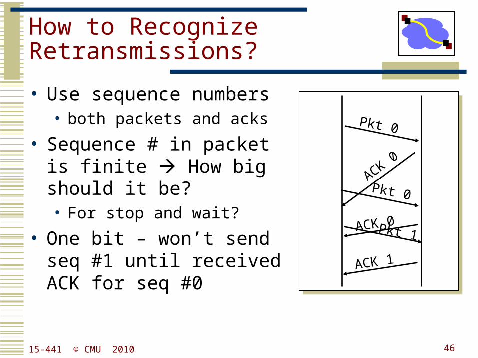
How to Recognize Retransmissions?
• Use sequence numbers• both packets and acks
• Sequence # in packet is finite How big should it be? • For stop and wait?
• One bit – won’t send seq #1 until received ACK for seq #0
Pkt 0
ACK 0
Pkt 0
ACK 1
Pkt 1ACK 0
4615-441 © CMU 2010
Issues with Window-based Protocol
• Receiver window size: # of out-of-sequence packets that the receiver can receive
• Sender window size: # of total outstanding packets that sender can send without acknowledged
• How to deal with sequence number wrap around?
4715-441 © CMU 2010
What is Used in Practice?
• No flow or error control.• E.g. regular Ethernet, just uses CRC for error detection
• Flow control only.• E.g. Gigabit Ethernet
• Flow and error control.• E.g. X.25 (older connection-based service at 64 Kbs
that guarantees reliable in order delivery of data)
4815-441 © CMU 2010

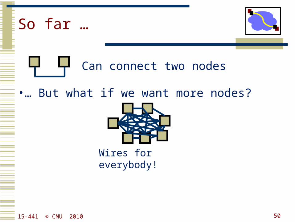
So far …
•… But what if we want more nodes?
Wires for everybody!
Can connect two nodes
4915-441 © CMU 2010
So far …
•… But what if we want more nodes?
Wires for everybody!
Can connect two nodes
5015-441 © CMU 2010
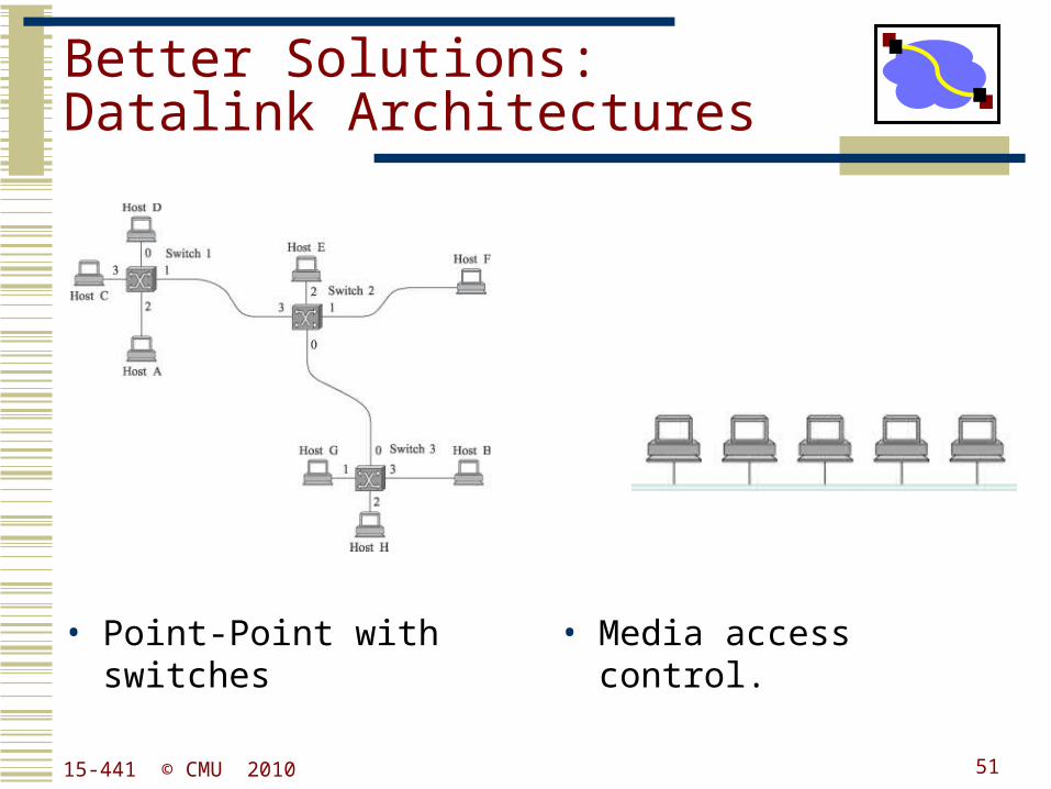
Better Solutions:Datalink Architectures
• Point-Point with switches • Media access control.
15-441 © CMU 2010 51