1.4i 16 - nasa · pdf filetable i lists the material weight ... inflation 3.5 x rated...
TRANSCRIPT
_ 1.4i 16
https://ntrs.nasa.gov/search.jsp?R=19740004392 2018-05-09T00:53:44+00:00Z

N7&-1250!

INASA Contract No. NAS-9-12040
DRL No. Exhibit"A"
Line Item No. 9
DRD No. MA 129T
dt_i ' 7
ENGINEERING REPORT NO 4230
PART II
NASA Wheel and Brake Material
Tradeoff Study for Space Shuttle
Type Environmental Requirements
May 8, 1973
B.F.GOODRICH AEA£.SPACE & DEFENSE PRODUCTS
Wheei and Brake Plant
T roy, Ohio
E:
_._._ •
_b
Chief Engineer
i
III
I
ER - 4239
FSC 97153
['ITLE PAGE
TAB i.E OF" CO?J i'I£?<TS
DISTRIBUTION I,IST
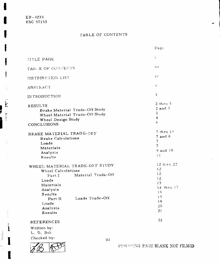
TABLE OF CONTENTS
_E) a_ e
i
iv
AB,qT R A C T
m_
IN TRODUC TION
RESULTS
Brake Material Trade-Off Study
Wheel Material Trade-Off Study
Wheel Design StudyC ONC LUSIONS
BRAKE MATERIAL TRADE-OFF
Brake Calculations
Loads
Materials
Analysis
Results
thru 5
and 3
7 thru 11
7 and 8
7
7
9 and I 0
It
WHEEL MATERIAL TRADE-OFF STUDY
Wheel Calculations
Part I Material Trade-Off
Loads
Materials
Analysis
R esults
Part II Loads Trade-Off
Loads
Anal,(sis
Results
l 2 thru *_
12
12
12
13
14 thr_ 17
lg
19
19
20
21
i
I
REFERENCES
Written by:
L. D. Bok
Checked by:iii
23
t,_.'.__,:'.,,._ _u_ BLANK NOT PIL_IP_/)

ER-4239
FSC 97153
i
iI
III
I
I
I
I
I
I
I
ABSTR AC T
NASA Wheel and Brake Material Trade-Off Study
This investigation covers material selection and trade-off for
the structural components of the wheel and brake optimizing
weight vs cost and feasibility for the space shuttle type ap-
plication. Analytical methods were used to determine section
thickness for various materials ending with a table showing
weight vs. cost trade-off. The wheel and brake were further
optimized by considering design philosophies that deviate from
standard aircraft specifications and designs that best utilize
the materials being considered.
V

ER -4Z39
FSC 97153
r_
INTR ODUC TION:
The purpose of this study was to design a lightweight wheel and
brake which would be lighter than the latest state-of-the-art
designs. To insure optimization between weight and cost, five
basic metals were considered: Steel, titanium, aluminum,
magnesium, and beryllium. For the wheel, the optimum
material was selected and the design was subjected to four
additional loading philisophies.
1
!

ER -4239
FSC 97153
RESULTS:
BRAKE MATERIAL TRADE-OFF STUDY
dlr"
Table I lists the material weight cost trade-off for the structural
components of the brake as shown by 14-1493-2. These components
when combined with the heat sink material, make up the total brake
weigat. There are two lightweight and heat sink materials under
consideration for the space shuttle type application; one bein_
structural carbon and the other being carbon or sintered iron lined
beryllium. The heat sink evaluation and study is reported in
Engineering Report No. 4239, Part III.
TABLE I
BRAKE MATERIAL TRADE-OFF STUDY
.m
WEIGHT WEIGH f BUDGE TA R YATEBIAL LBS SAVED (LBS) PRICES **
Piston Housing
Alun_inum 15.4 .... $ 340. O0 ....
• cosT/ ]
LBS SAVED/
tMa gne si.urn
Torque TubeQ
9.6 5.8 $ 400.00 $10. Z0
Steel 34.6 .... $ 525.00 ....
Titanium 19.7 15.0 $I, 878.00 90. Z
Beryllium lZ. 7 21.9 $6,600.00 $277.69
Back Plate
Fitanit_m 7. 769 .... $ 800.00 .... II
* COST/iBS SAVED = Difference in Price ** Based on 100 Piece Order
Difference in Weight
Z
ER-4239
FSC 97153
- _. j
I
I
I
I
i
|
I
I
I
I
I
I
I
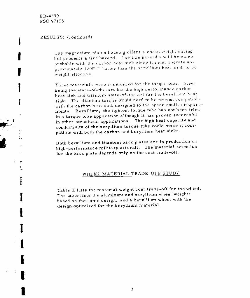
RESULTS: (continued)
The magnesium piston housing offers a cheap weight saving
but presents a fire hazard. The fire hazard would be more
probable with the carbon heat sink since it must operate ap-
proximately I('0("(;V hotter than the bcry[liun_ heat sink to be
weight effective.
Three materials were considered for the torque tube. Steel
being the state-of-the-art for the high performance carbon
heat sink and titanium state-of-the art for the beryllium heat
sink. The titanium torque would need to be proven compatibl_
with the carbon heat sink designed to the space shuttle require-
merits. Beryllium, the lightest torque tube has not been tried
in a torque tube application although it has proven successful
in other structural applications. The high heat capacity and
conductivity of the beryllium torque tube could make it com-
patible with both the carbon and beryllium heat sinks.
Both beryllium and titanium back plates are in production on
high-performance military aircraft. The material selection
for the back plate depends only on the cost trade-off.
WHEEL MATERIAL TRADE-OlaF STUDY
Table II lists the material weight cost trade-off for the wheel.
The table lists the aluminum and beryllium wheel weights
based on the same design, and a beryllium wheel with the
design optimized for the beryllium material.
ER -4239
FSC 97153
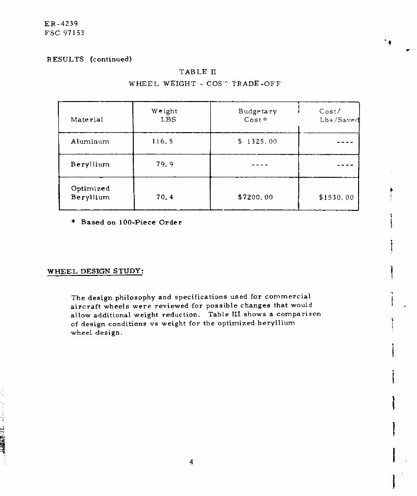
R ESULTS (continued)
TABLE II
WHEEL WEIGHT - COS _ TRADE-OFF
'Q
Material
Aluminum
Beryllium
Optimized
Beryllium
WeightLBS
116.5
79.9
70.4
Budgetary
Cost _-
$ 1325.00
$7200.00
Cost/
Lbs/Saree
$1530.00
* Based on 100-Piece Order
WHEEL DESIGN STUDY:
The design philosophy and specifications used for commercial
aircraft wheels were reviewed for possible changes that wouId
allow additional weight reduction. Table III shows a comparison
of design conditions vs weight for the optimized beryllium
wheel design.
4

IIIl
ER- 4239
FSC 97153
RESULTS: (continued)
TAB [.F III
DESIGN CONDITION VS WEIGHT
g,
!.
{
_v
=t
1
!
!
!
'Load
Condition *
1 **
3
4
Ti.re
Deflection
@ Rotor Load
@ -55°F
37%
3z%
40°70
40%
40°70
Burst
Pre s sure
t. 5 x Bottoming
Pre ssure
3.5 x Rated
Inflation
I. 5 x Bottoming
Pre ssure
3. 5 x Rated
Inflation
3.5 x Rated
Inflation
Design
Load
Limi.t
Comb.
Ultimate
Comb.
Limit
Comb.
Ultimate
Comb.
Limit
Comb.
** Load Condition used in the weight cost trade-off study.
* Roll Life 100 miles for all conditions.
\Veigh_
70.4
91.6
68.6
84.7
77.2
!

ER -4Z39
FSC 97153
C ONC LUSICNS:
1
I .
Z°
.
.
The lightest brake would consist of a magnesium piston housing,
beryllium torque tube and beryllium back plate.
The magnesium piston housing and beryllium back plate
are cu:rrent state-of-the art designs and need no develop-
ment. The beryllium torque tube would require development,
but would offer' a low cost weight saving even when compared
to the titanium torque tube.
The beryllium wheel offers the greatest potential weight
saving in current lightweight wheel and brake designs. The
development of the wheel would be expensive and the appli-
cation would have to justify $1,500.00 cost per pound weightsaved.
The wheel design study indicated that design philosophies and
specifications used for commercial and military applications
could unnecessarily penalize the space shuttle, weight wise.
Careful consideration should be given to tire deflection,
wheel burst pressure, and trade-off in designing the wheel
to limit or ultimate load conditions.
I
I
I
I
I
I
I
i
!
[
[
1
I
I
I
I
I
ER -4239
FFC 97153
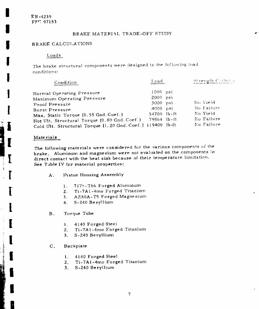
BRAKE MATERI%L TRADE-OFF STUDY
BRAKE CALCULATIONS
Loads
The brake structural components were designed to the following load
conditions:
Condition Load _ rot_gth (" ,,; to I-i:,
Normal Operating Pressure 1000 psi
Maximum Operating Pressure 2000 psi
Proof Pressure 3000 psi
Burst Pressure 4000 psi
Max. Static Torque (0.55 Gnd. Coef.) 54700 lb-ft
Hot Ult. Structural Torque (0.80 Gnd. Coef.) 79564 lb-ft
Cold Ult. Structural Torque {1.20 Gnd. Coef.) 119400 lb-ft
N_ Yield
No Failure
No Yield
No Failure
No Failure
Mate rials
The following materials were considered for the various components of the
brake. Aluminum and magnesium were not evaluated on the components "n
direct contact with the heat sink because of their temperature limitation.
See T_ble IV for material properties:
A. Piston Housing Assembly
1. 7175-T66 Forged Aluminum
Z. Ti-7A1-4mo Forged Titanium
3. AZ80A-T5 Forged Magnesium
4. S-240 Beryllium
B. Torque Tube
1. 4140 Forged Steel
2. Ti-7A l-4mo Forged Titanium
3. S-240 Beryllium
C. Backplate
1. 4140 Forged Steel
2. Ti-7AI-4mo Forged Titanium
3. S-240 Beryllium
ER-4239
FSC 97 153
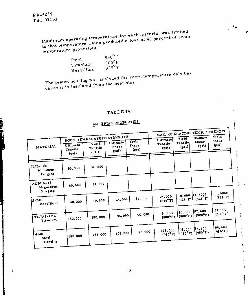
Maximum operating temperature for each material was limited
to that temperature which produced a loss of 40 percent of room
temperature properties.
Steel 950°F
Titanium 900°F
Beryllium 825°F
The piston housing was analyzed for roor_ temperature only be-
cause it is insulated from the heat sink.
TABLE IV
MA TERIAL PR OPER T_ES
MATERIAL
7175-T66
Aluminum
Forging
AZ80 A-T5
Magnesiurn
Forging
S-240
Beryllium
Ti-7A 1-4Me
ROOM TEMPERATURE STRENGTH
UltimateTensile
(p,i)
q
86,000
YieldTensile
(psi)
76,000
50,000 34,000
,,, , .., , ,
40,000 30. 000
, , |1
Ultimate YieldShear Shear
{psi) (psi)
,', , _ i _' " '
24,000 18.000
MAX. OPEBATING TEMP.
Ultimate
Tensile
(psi)
24,000
(825°F)
ie ld
Tensile
(psi}
18,000
(825°F)
Titanium 160,000
, , i
4140
Steel 180, 000
Forging
[50,000
163,000
96,000
108,000
90,000
98,000
96,000
(900°F)
108,000(gS0°F)
90,000
(go@F)
98,000
(950°F)
STREINGTH
Ultimate Yield
Shear Shear
(psi) (psl)
.... :_
14,4000
(SZS°F)
57,600
(900°F)
64.800(950°F)
11,9000
(825°F)
54,000
[900°F)
58,800(950°F)

I
I
I
I
I
I
i
!!
[
[
[
[
ER -4239
ESC 97153
ANALYSIS
The methods of anaysis are shown here and not the actual values
for each component of the brake:
Piston Housing:
d = 14.5
d e = 10.0
1.5Moment at A =
fPT
d I
_'B
PT = total thrusl load= 19.8p
(d- d A) (d I + d2)2 12, d (6co + d I - c,2)o03 - a (),a 3 -_,a, _ b 3/k I) 1 )11"3
1.5 (d, +d2)2/6_*d , -d2)6o3 +a(Xa 2 - _a, Xb 2 /Xb,)It :_
where: _a 1 =
Ab I =
Aa 2 =
Ab 2 =
_,a 3 :
Xb 3 :
b =
24/l(a/b) - I]
IS.6l(a/b) 2 +.S3911a/bl(alb) 2 - II
15.6[.539(alb) 2 + 1]l[(alb)2. I]
24albl[ (a/b) 2 - I ]
{(2.483 Inalbl[(alb) 2- 1]} + .668
I(2.483 alb In a/b)l[(alb) _- I] } + .6681alb
dAl2
dB/2
l
[l
I
i, I!l
Moment at B = (Xb3P T + Xb2M A)/Ab,
and stressesat A & B are:
aA = 6MAItA2
a s : 6M B/t 2
ER -4239
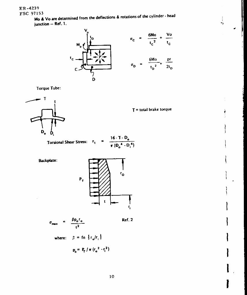
FSC 97153
Mo & Vo are determined from the deflections & rotations of the cylinder - headjunction - Ref. 1.
vot o
t c
D
0 c
6Mo Vo
tc 2 tc
O D =
6Mo pr+
tD2 2t D
Torque Tube:
..p....,_ T t
Torsional Shear Stress: r I z
T = total brake torque
16-T- D O
11"(O o4 D|4)
Backplate:
where:
PT
t
= fn | ro/r I }
po= PT/lr (ro= -rlZ )
r o
ri
Ref. 2
10
")
/
I
I
I
I
!
ee
I
I
1
I
_R -4239
FSC 97153
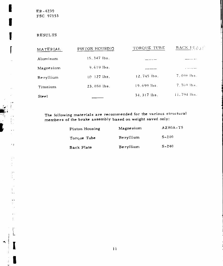
RESULTS
MA TER IAL
Aluminum
Magne sium
Beryllium
Titanium
PISTON HOUSING
15. 347 Ibs.
9.619 Ibs.
lO 127 Ibs.
23. 050 Ibs.
TOIR QUE TUBE
12.745 Ibs.
19.699 lbs.
BACK t_I.A i /
Steel 34.317 lbs. It. 794 lbs.
The following materials are recommended for the various structural
members of the brake assembly based on weight saved only:
Pi ston Housing Magnesium A _ 80A - T 5
Torque Tube Beryllium S-Z40
Back Plate Beryllium S-240
J
r
.
!
l
!11

ER-4Z39
FSC 97153
WHEEL MATERIAL TRADE-OFF STUDY
WHEEL CALCULATIONS:
PART I: MATERIAL TR%DE-OFF
Loads
?
9_
The loads shown assume a 49 x 17 tire loaded to 37% deflection:
Inflation Pressure
Burst Pressure
Limit Combined Load
Roll Load
Z93 psi @ R T
224 psi @ -55°F
510 psi @ RT
168, 000 lb. radial
+ 59,0001b. side
@ -55°F
60,000 lb. for 100 miles
@RT
lZ
I
I
I

I
I
I
I
I
1
I
'I
r_- r
_T
I
I
!
1
I
'!l
FR-4239
FSC 97153
MA TER IA LS
All materials are forged except for beryllium which is hot pressed.
See Table V.
TAB LF V
MATFRIAI. PROPERTIES (Values are in ksi)
Material
7049-T73 Alum.
2014-T6 Alum.
7075-T73 Alum.
7175-T66 Alum.
ZK60A-T6 Mag.
FK31A-T6 Mag.
Ti-6A l-4V-Tit.
-- -L
Ti-7A 1 -4Mo Tit.
4340 Steel
tu
F
72.0
65.0
66.0
86.0
42.0
45.0
160.0
170.0
180.0
4140 Steel
m
I.,
.,,I
i i
62.0
55.0
56.0
,,,
76.0
26.0
26.0
150.0
160.0
163. 0
163.0
tu
74.0
67.0
68.0
88.5
45.0
48.0
181.0
192.0
186.0
186.0
71.0
ty i
57.5
58.5
79.5
28.5
28. 5
171.0
182.5
170.0
170. I)
i
1
60.0
F ', 1 ttl_ :-"
10.
c).o
105
5. 0
5, I)
180.0
(Brush S-350) 66.0
Beryllium
55.0
38.0
38.0
!13
ER-4239
FSC 97153
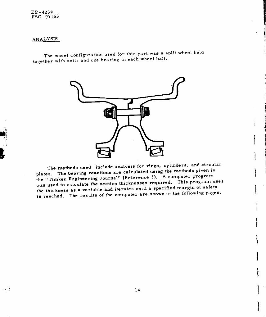
ANALYSIS
The wheel configuration used for this part was a split wheel held
together with bolts and one bearing in each wheel half.
The methods used include analysis for rings, cylinders, and circular
plates. The bearing reactions are calculated using the methods given in
the "Timken rngineering Journal" (Reference 3). A computer program
was used to calculate the section thicknesses required. This program uses
the thickness as a variable and iterates until a specified margin of safety
is reached. The results of the computer are shown in the following pages.
14
I
!
I
!
I
I
I
[iI
[
I
[
_L
EI_ -4239
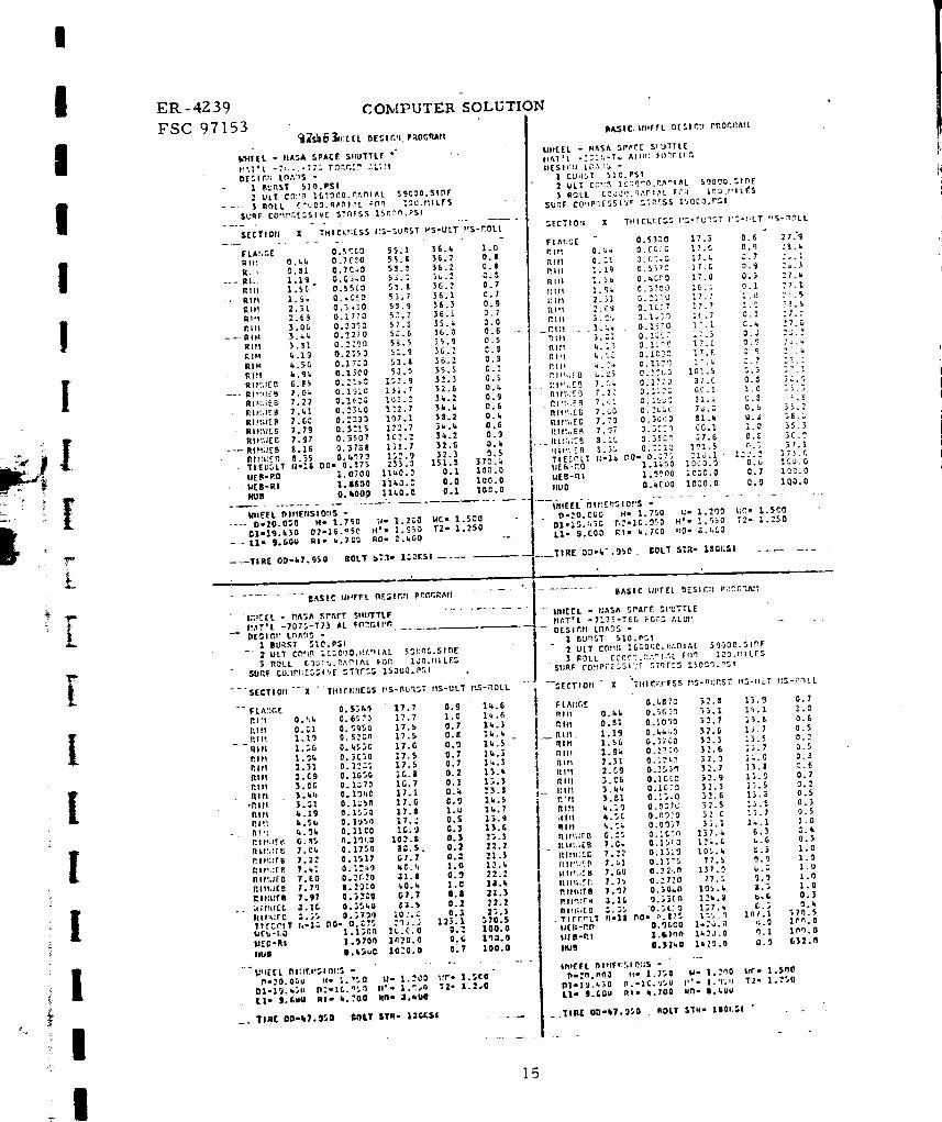
FSC 97153_s_},:r[L ol_:tr,ll.Paoor_i
k_4[IL - rlASA SPACE $ItU_TLI "" "
/;_T'L -7:,+;-_;; r_P,Y.:_ :,L;'|
DE$1f+I; Lno','+$ -
| B_rtST S]O.PSI
7 ULT CO_!T_ IG'_O(_0.P,;.ntAL 29690.SInF
• --- $ ROLl. {_'UOD.q_I,_L Ftlrt 10G.tllLIrS - "
SURF CO_PF.E,%$1V[ ST_rS_, 1$_._q.P$l
S[CTiOti X THICKr:E$$ i:$-r, UP,$T _S-ULT PfS-COLL
COMPUTER SOLUTION
IU_IC I._llffL _[Slttt pROC.fl^tl
I/If(EL - NASA '_P,_C[" StlUTTC[
I1_1'L -:=::,-T_ All:l: f()_r, tt_
I1($1(;!i LO,'m_ -
I [WIL, T 516.PS1
2 L_L'T (',',,':_ _C:;9"0.r_'_lt_L $9000..51_[
} ROLL _C_:_Y_h'_,_I,_L F_':l l_O,t'lL£$
SUrF CO!IP_ESSI'/r C.T_*rs$ 150C0.P_'1
FLAtIG[ O.5'_C0 59.1 36.1 1.O
Ill z O._,_ 0.7£."0 55.1 36.7 0.1
R _ 0.$1 0.7C.0 53._" 36.2 0.0--- Rh. %.11 O. {; 3.._ 5_.; 3_.2 C.S
Rill 1.56 0.55C:_ 55.$ }G.2 0.7
-- RI_I 1.%;, 0._. ,_ O _.7 36.1 C.7
RI_ 2.31 0.3w_0 SS,9 35.3 0.9
i;l_l 2.6_' 0.1770 5:.7 36.1 0.7
Rill ].OG O.Z_O 57._ ]5.t 0.0
---RIM - 2. _.;, 0.2270 5_.6 36.0 0,6
RUt 3.S1 0 .... 5_.5 35.9 0.5
RP4 L19 O.215_ 5_.9 36.2 C.3
RIM I.SG 0.17:0 53.& 36.2 0.3
- - Rl_l i._:_. 0.1_O 53.0 35.5 G.2
RIl:tlEt'l E.$5 O.:bO 152.9 32.3 0.$
-- RII_IIE_ ).0_ 0.I$_0 151.7 ._2.6 0._
Rlt;:_8 7.22 0o16=_ 102 .2 3_*.2 0.9
RIt:;IrB 7._?, O.."3_,0 172.7 3_.k 0,6
RI#',;;E P 7.6_ 0.:=30 107.1 3L2 O.t,
Rib:lit..5 1.79 0.3:!5 ).22.7 _i._ 0.6
RII::IEC 7.97 0.3507 102.= 3_.2 0.9
--- RI_':;;[B 8.26 0,37C,8 131.7 32.6 O.i
It Ir'l:Ell 8.35 O. _'_73 152.9 32,3 O.S-- TIEBC_LT /J*Zl DO_ 0.37_ 23}.3 151.3 37_._
IlEB-l_O :.O700 11_0.9 0.I 100.0
gEB-RI 1. i600 111,_. C 0o0 100.0
HUts O. kOO.0 11¢,0.0 0.1 100.0
I/H£EL Dltfl_NSIO:IS -
.... 0'.20.0_0 X- 1.720 ;,_* 1.2C0 HC- 1.500
1_1-19.',30 02-16.750 H'" 1.853 T2" 1.250
- - tl" 9.60U kl= _,,7.50 P.O= -_.lO0
----TIRE OD-k7.9$O BOLT _,T_- 1,_K,,5,!
Irte- C_r - 0.$31_ ].7.3 0.6 ."7.'9
P,Itt 0.:*_ 0.CC_O 17.6 0._ 2_._*
_llt 0.:I _. {2.C 17._ _.7 7_.L
hilt 1.19 0.5_7_ 17.G _.9 2&.t
I1.111 1._b 0. _C,," _ 17.0 0._ 27.k
l*. l el 1.97. 0.;TCJ ZC.; 0.1 ."7.1
l/Ill 2.31 (_. : I,: LI _7.7 1.0 ._._
RI'I ,_.C9 0. _. C,', 7 I7.7 _..9 ?I.S
P.ttl 3.CL, _.l,:0 :[.7 _,.1 :7.c
_P.III . .2._:+ . 0.1970 _.7._. C.i¢ :7._
R_/I 3.;: O. _;<:-c ;.;.5 0.,; =_.-_
Rl_ Ll._] 0.1r_c 17.C 0.9 7_,I
i Pill _.:; 0.I]:_ 07._ :.7 ::.:
P. I_!,:._ B I;.7_ O. _t,O 10:,.5 ,_.3 :.7!
;'I'_,,E_ 7.5;. 0.1710 37.C 0.3 3,_._
RI _;.r'3 7.._: 0. :.526. 66.1 1.0 :_,3
I rll_;.[ 6 7.CD 0..%;.ll 71_.; 0.5 -r_ -,
I RI,",_;E C 7.7_ O.._i,},10 $1.I tl.J 36._f',l t_IzE_ 7._7 0.;:?I 66.1 _.0 35.3
._ lli::_;._9 3.16 0.35C_ 17.5 0.8 3C.?ill.'. [ fl 3.35 0.::1_ 1P, I.5 n.3 37.1
TIESCLT I;'18 i_O* 0.;7_ 71_,.1 ' 1=2.= 373.Clie E .,',O 1.1L_0 I_CO.O 0.u IC0.0
l_EB-rti I. _'?o0 ; _C,_.O _.7 1_0.0
IIUO O.GCO0 1000.0 0.9 lq0.O
t/tlEEL- DIt:-_rlsIO;'S -" ..............
_ P-._O.CCO H* 1.750 l:- 1.2r}0 t;r,- 1.260
01.15.:,36 r,._-IC._50 H'- 1.5_0 T.TM 1.250
I1_,. _.C00 Rl" k.7CO t10- _.z.CO
.___TIRE D:)-IC.9$O_ I;0LT 5=_- lS_i;SI ........
.......... _AS|C Ilt_t_l_l. n£$1f',;I pR_r.P, AM .... " " .......... BASIC llllFE{ l)E511?l PI;OC,_,A:I
" I_;!_IEI. " IVC,_ 5,'V,M: $tlUT'rLI ............. Illi[[L - II°L';^ ._t'AI'E $1'U'_TL[
I',._TiL -707.5-77} AL F_GII!_ tim',IlL -7_75-T_ra FGr:; ,*,LUP.
_-DE";IO *_ LOA.qS - " .... DESI_,II Ln/_DS -
I BU,'IST _,l(?,PSI 1 BU_S'I' $10.P.51
-' 2 ULT Cr_,_ ZCCCOO.I!_IilM. 55001_.$10E - 2 ULT COtI_J !C_,O_;_.ilt, l'llAL 5g0DO.5I_F
ROLL C30('..._,_PIAL FOP. 1J0.f11LE"- 3 ROLL CCOC":._,;._I,',L FfI", ].=0.lllLI-S
SURF CU;IPI_[S_-I_i[ ._T_FS_ 150U0.P_I . SURF ('O_!PZ[_,SI'/P STq[_, 1500'}.nSI
15

--L
4;
+
ER-4239
FSC 97153CO:,_PU'fER SOLUTION
IIA$1t_ Itll[l'L U[_tGII PiiOr.ltAl|
I/lirtL - I;A_,A sr,,_rr P,liUTTLI" . o
I)[SINII l.lsA:_$ o -- ....
1 Run.&! _,10. r&!
t Utl Cot_r'. I_.',0_=.R,_nI,%L Sqt_o0.Sl.£
3 nOll COOCU.It,%_IAL Irort :."_.,II[$
SUIIF f(':iP_¢f_._lV£ ";Tt:f.%S I_)GUO.PSI
$1[cYlo:: X
IrLA_:GE 0.}_70 .'5.C, ?.7 0.$
_lr_ 0.4; o. ,_z,7o 2s.7 ?.1 0.0
I'Jll 0.31 0. _'_7t) :5._ ).G 0.S
I11H 2.29 O..?-.20 2._._ 7.5 C.3
R|II 1.Sn 0.170'9 25.0 ?._ 0._
Rlt', 1.90 0.07_a .%.6 ?.7 0.0
Rill 2.31 O.o'31_ Z5.5 7.7 O.E
I_ltl :.C_ O.LZ;C, :5.0 3.0 1.0
P, Itl ).C £ O._'IS +.S._ 7.5 O.b
Rill _;. k_. O.gr.SG ?5.0 7.1 0.7
11111 .3.._ C. 0:+_,++ .+5.3 ?.9 0.0
_!II k.19 I_. t-,30 . :5.6 T.7 O.&
Rift k.5G O. 0i%'* 9 :5.| ?.ej 0._
_. Rlrl,lEB 7.1.* . C.101_2 1.17.-' 0.. _ _ 5.0 ....
nJt_.;EU 7.3. + 0._976 170.5 0.9 S.&
I.'llll_[5 7.7_ 0.07_i. • _27._ 0.6 2.2
Jt I':;_£11 ?.39 0.1600 2._3.." 1.0 1.4
P_IJ:I:[_ _,.07 0.?050 175.; 0._ S.k
P. li%.'r.B :.2G 0.2310 1.17.- _ 0.2 5.0 .....
RI:lZ:_B _.'+5 0..".C,50 2_=.9 0._ 5.$
TI(I_OLT 81-11 OO- 0.._?S _,Sn.S 89.4 5;,9.2
UC "_- i',O 0. G 7_.O .+_C_. 0 103 _33.0
IIEB-RI 3,]_'00 _0C0.0 0.k _$0.b
ItU[_ 0.15,30 2gc0.0 0.0 lkl.2
TIJII_I:J?E"-S I:S-_t;_I.%T I;S-UL1 llS*rtOLL
U'r_[EL OIt:ECSIOP:_ *
• 0-20.00_, H- 1.7S0 II* 1.2C0 t_,. 1.000
Dl-15.11r. 1,2-16.950 ,'- 1.950 T2- 1.150
Lie 9.600 I11- ".700 RO- ".400
|A$1C Utt_L DtSIIWI PftOCRJUt
$:lllrlL - llASA SPP, cr _IIUTTI_
pl_T _. -'_.,...:..,. TIT.y,j_-! + peP,_
I P+Ui: ,_ T $1,.P$1
) I:OLL C_SC_.;ZAnI_L ro,, lO_.ttlLr_
S[_TlOfi X TIIICI:III'SS tIS-LLrlST tl$-ULT it._*"tOLL
- ELAt_G[ - 0.3350 _2.._ |$.5 0.S
IIIPI O.;l_ 0.2'_++ 0 )._.? l._.¼ O.k
t:Irl 1.19 0.2.;_0 31.3 13.: 3.1
_.lil 1.5C, O. ;.c:0 _:.7 13.: 0.9
P, IJI 1.'_ 0.07_.0 )_.r, 1!,.7 0.I
Rltl 2.3I 0. _'J:5 _12.7 15.8 0._1
ffl_t .+.r,9 o.ro:o 3._._ 13.2 :.2
I,+I tt .;.CO 0.C:+15 32.1_ _)._ 0.5
i,+lit _. t+_. 0.0_[,0 3_.g 13.L 0.0
Jilt) _.3; 0. _1_: 52._ 2,5._ 0.$
trill _,.I_ O. _*::, 3:.7 13.3 0._
I1111 _.50 0. C%'.l, ._2.7 ;._.: O.cJ
l_. I .*1 k,.n:+ O. _+17 33._ :_.7 0._
I; IPll!EB 6.05 0.+.0_7 I')9.$ :.? 0.9
ItlPI;,EB 7.1.* 0.;_5 ;_';..* 2.L: 0.$
P.I_;[ C T.51 0.0_£0 ;65.5 _.5 0.k
Ili!txlES 7.70 0.(_;50 150.; 5.k 0.$
ptIJII:CI_ 7._g O.15r0 2_r.5 ?,G 0.4
IIIiil+£O 3._7 0.lgC0 _. Sll. 5 3., _ 0.Y
__ P,I"1%1[_ |.._G 0.-'._50 I09.10 2._ 0.:
i_ lrr, zr _ :. :,_, 0.:;_ _.; .%9 _._
TIE"_OLT rl-lS 00- G..175 161.5 , '_3.g 571.1IlE_-l:O O.GS_ 3100._1 0.2 251..1
I/E8-RI 1._360 31L'0.0 0.2 2"0.3
HUB 0.1k:0 3100.0 O.7 125.1
.._TI_[ OD-47.950 BOLT s'Te- 111011"-I
(_4E££ Dlr'Cr SlOt.') -
G-20.00_ i;- 1.750 II- 1..*UO l:P- 1.0C,0
D1"19.%._0 ,:-16.%O It'- 1.950 T1- 1.150
Lle 9.600 _Ii- k.700 RO- _._00
•TIOE. 00-:.?. ]r. 0 . BOLT ST".- 13012SI ......
IASlC Will[EL DESll_lll PIIOG_IUI_..
BASIC I/HEEL I_ESIr, il Pi_Or-_l
I:H/EL * PJA3A SPACE _JIUTTLE b'NErL - II,_SA SP_CE SJ+UTTL/
ItATeL - Zt:-G_,A I'..%r. FCR_ "- ............. t_&T'L -E;:;le,-T& ),_.,.r_ FDR_
OESIGI: LOA;)S * OESIGfl LO_e.OS -I B_RST S10.PS! ..... - I fl,U_S T 510.PSI
2 ULT CC:_0 16_0U0.RAI_IAL ))000.SIDE 2 ULT C_:_9 "-_-'_C._;,'_I_L _9:0O.Sli'_ir
3 le_LL G(_0CU._,e._IAL F.Otl 1Cg.J*.iLES 3 ROLL GC_0._,'_DI,*,L FO,_, _.HILE._
SUrF COl:;'_[S$1:'[ STi_ES$ G000.P$I SURF (O!!PRE._._JVE ':-T9£$5 60OO.PSI
$I[CTIO/! Z IHICKtlESS r+$*OURST ilS-ULT IIS*_0LL* $l[CTlOIl
FLAI:G£ 0.7;,30 17.S 0.l +$1.S
RIM O.&i 1.2200 17.1 0.t 31.O
lilt 0.11 1.1500 17.2 0.5 31.1
-- llJI 1.19 ] .0700 1C.7 0.1 30._
Rill 1.5G 0.9?_0 17.7 1.0 31.9
RIll l.tk 0.8950 17.6 O._J 31.7
RI_I 2.11 O. 7;;'_ 17.0 1.0 32._.
RIM" 2.00 O._C_O 17..$ 0.8 31.&
RIM 3.06 O.kG_O 1.'._ 0.6 31.S
--_. RIM J.ki 0.3C$0 17 3 0.1 Sl.k
RIll S.01 G, 3_*)0 17.6 0.5 31.8
RJI_ i.lt O. 3C10 17.3 0.1 31.6
lltl 4.30 0.)7'_C 17.5 0.l 31,l
Hi!4 4.i:, 0.17_0 17.7 1.0 31.9
l If.',_FO 0.13 0.$200 lll.i 0.I 70.I
Rift lEO 7.0k 0. II, O0 173.6 0.7 13.b
RII%IEI 1.22 0.2rkO _J.S 0.$ 2l.k
RI :'_H.8 7.;I 0.)110 1.7 0._ 25.0
RII,;IE_ ?.SO 0._,100 0.b _)._ 1£0.?
P, I/%'E I: 7.7_ O.kl_OO 1.7 0.2 23.0
llli:t+fO 7.SI 0.71130 S.S 0.5 II.4
RI;_l:f_ 1.1£ i.$lnO 173.6 0.7 13.4
RI::;tO i..5 101._, 0.2 ?G.l
UfB-RO 1.7200 4.*,'1.0 1.0 iO0.O
UEB'RI _,9000 II00.0 0.1 100.0
NUI 1.0'200 /20.0 0.4 liS.O
X _ TtlICIll[_S JI$-BURST /IS-ULT ilS-ffOLL
FLAtJG[ O. 7130 17.$ 0.1 3].1
Rill O.kll 1.2200 17.4 0.7 31.8
RIM 0.31 1.11_0 17.7 1.0 32.2
• RIM 1.19 1.07C0 17.i 0.7 _3.$
RIM 1.50 0.9800 16.7 0.1 30.7
RIM 1.94 0. |_g0 17.6 0.9 32.0
Rill 2.31 0.7:_ 17.5 O.I J1.5
Rill 2.Et 0.6500 17.7 o.q 32.1
Rill ).06 0.25:,0 lr,.9 0.3 31.0
-- RiM 3. _,;_ O. )GCO 16.g 0.) 3].0
RIM 3._1 O. 3_50 17.2 0.0 31.S
RIH 1.I$ 0.3690 17.3 •0.6 31.[,
Rift 4.$_ 0.1774 17.5 0.| 31.9
RIll _,.gk 0. $70.0 17.6 0.9 .12.1
RIJ_Ur R 0.8') 0.110_ 177.2 0.7 75.3
Rlt;:;F.O ?.Oi 0.17_0 16(.k 0.1 £2.]_
R I I_;./.r _, 7.7l 0.20_.0 10.7 0.0 2q.b
ffl e'+;t{ R 7.kl 0.1170 3.S O.i 13._
rlle+l;Pi ;.{_ 0. _,0_3 0.G $0.0 110.O
R IJ_tl[R 7.71 O.&?/O ).S O.k 2_..1
Rll;il[O 7,*j7 0.5_00 |0._7 0.$ 19.b
Rlfil_F C I.|C 0.57&4 I_6.4 0.3 IZ.2
_lJ_t;tu I.)S O.&lqO ]7_._ 0.7 75.STI[_OLT +I-I_ 00- 0.?50 21£.S 130.') ._'I.-
11111",'10 I. 7_00 02,_. 0 1.0 10.2.O
U[O-RI 1.q900 I020.0 0./ 100.O
IIUI 1.0000 o &20.O O.i Ik+,.O
t_l[[L OIII_IISIDII_, -
O-_0.0UO li- 1,7_/_ t/e 1,200 IJP.o l.SOf_
111-|0.100 fl;-I{.910 II'- I.+:0 TI- I.I$0
L I- 1.6U0 l_i* k.700 RO* 8.k00
o TIR[ 00-47.9S0 OOLT ._TR,. 11010SI. * -
lilll(L OIt_;lIllOll._ -
O-2O.C_0 It. 1.750 II- 1.2110 Ill.- !.$OO"
n!-1113o ,2,,IL._$_ ii I_ 1._.',o TI,, 1.11o
LIo !.io0 I1,,, 1.100 Io,,, I.I00
TIU OD-lll.l_| OOtT STR- 11Oi;$1 .....
16

I
I
!
!
I
I
i
+!
I
|
I
I
II
!iI
ER=4239
FSC 97153
COMPUTER SOLUTION
BASIC IIPfEFI. IIESI_P! PRO_RIt*A
tJHEEL o tZASA SP#.CE StlUTTLE ......IqAT'L -170!.SI tfZrlO STEELDKSIP, r; LnM:S -
I PUP.ST 510.PSI2 ULT CO_:PLI_0t_0.Rr, DIAI 59P_U0._,IDE3 ROLL GOO0O.P,P_IAL rnrt lfl0.PIILES
SURF COttP+_ES$1,/E ._T|tE_S 300"OIl. PSI
:ECTIOI! X THLCIttlESS ttS_-P,uRST ft.'_-ULT ftS-RflLL"
. +FLAIIGE 0.3130Rill 0.1111 0.31;_0RIM g.31 0.2700
-- RIFt . 1.19 0.23.70RIH 1.56 0.1r+50Rill 1.9l+ 0.0723Rill 2.31 0.O=SI_Rill 2.G9 0.0_:00Rill 3.O6 0.0_3
__.Rill ._.k,k 0.0k00RII4 $.gl 0.0379RIP! 4.19 0.0300RIB koS6 0.0360
. Rill 4.9k 0.0tO0RII_IEB 7.10 0.0000
_ RlllttEB 7.29 0.1]�c.I)RII_£B 7.47 0.0910RII_CB 7.6[; 0.0813RII_ICB 7.85 0,007:RtI#JJPG . _.Ob 0.;3£0RII_EB 2.22 0.171+0
._ RIIt$IEC 3,111 0.1970RlllU(B ,). '_0 0. 2115+_TIFCOLT 11-18 I_0= 0._75I/(R-RO O. 64 tiffIJEB-RI 1.2200IlUB 0.1450
'UttEEL I_lr+rflSlOPZ$ 2+D..20. Ou_ I+= 1.7_0
D1o19.430 02*10. 950LI" 9.000 RIo k.700
............ 1_
17.7 0.9 111.017.3 0.6 13.61+,; 0.2 12.'3:..7. _ 0.9 13.9
17.$ 0.6 13,11 .17.1+ 0.7 13.617.6 0.9 14.01G.G 0.O 12.617,5 0._ 13,817.6 0.9 13.9 ....17.S 0.9 14.O17.3 0.8 13.517.0 0.3 13.116.7 0.1 12.7
177.0 0.5 29.117=.1t 0,7 29,3170.3 0.9 29.1150.1 0.8 27.R
5.9t++g:t t,,170.3 0.9 29.117P..k 0.7 29.3177.6 0.5 29.1151.0 07.0 951_. _
_IGO.O 0.8 100.03100.0 0.II 100.O3160.0 0.6 2782.6
t_- 1.200 tiC. 0.G00,',, 1.9_0 T2= I.O00RO- 8,£+00
.......... BASIC UHEEL DESIG'I PROP_RAPI
.... TIRE OD,k7.�SO
tIHEEL - tlASA SPACE S_UTTLEItATeL " 5-35_ _ERYLLIUt_DE$1G_J L_ADS -
1 BURST 51n. PSl2 ULT COflB I_000._A_IAL3 ROLL G0_00._I_L FO_
SURF COPtPRFSSIVE _T;:ESS
SECTIOII-X
+5900G.SIPE
100.PtlLEBO.PSI
TtlICKIIES_ HS-BURST PtS-ULT tt$-_OLL
FL_,flGE 0,5_80 17.3 0.6 31.3RII] O. 11_, 0.7250 17.7 1.0 32.3RIIt 0.£1 0,($670 17.7 1.0 82.2Rift . _. 1.19 0._000 17.G 0.8 81.3RIft 1._6 0.521_0 17.6 C.8 81._1Rift 1.9k 0._+330 17.5 0,8 81._flit] 2,31 0.23q0 1"7.7 0.9 82.1Rift ?.u9 O. 17U0 17.3 0.6 ;_1.2Rift 3.00 0.1950 17.O 0.5 g0.S
.AIJI _ 3._k 0.2070 17.3 0.5 31.3Rift 3.81 0.2000 17.1 0.11 _0.3RI_I 4.19 O.1690 17.5 0._1 _1.+ +RIIt 4.56 0.10_;0 17.6 0.3 81._JRltt 4.9_+ o. 11._0 IC.B 0.2 _0.1RIf,qlEB 6.8.5 O. 19P,o 99.6 o.: 10_.2RIfflER 7.011 0.1uo0 87.8 O.11 lO0._It I Itt,,+rB 7.22 0.1570 G9.0 0.1 _G.1RII_IEC 7.1tl 0.1307 11:). 9 0.9 91._RIIIUEB 7.60 0.2._+0 73.2 0.3 1C _,,.9RII:IIEB 7.79 0.2030 k3,9 0.9 91.._R ItP, IEB 7.97 0.3220 K�.0 O.1 96.1Itlft;;EO 8.10 0.3tt70 87.8 0.11 1Cfl.3P,I t,_tE9 3.35 0.3710 99,6 0.8 lC:+. 2TIE�OLT 1t,,13 DO= 0.750 25_t.8 ln.2.11 01.P.IIEE-ItO 1.1110P 1000.0 0.0 197.7IIEB-RI 1.990U 1000.0 0.7 233.3IIUB 0.4600 1000.0 0.9 3_7.S
I/HEEL OI/IEtJSIOP_S -0=20.000 I1= 1.7S0 tl- 1.200 t+C,, 0.60t_
D1"19.1130 D2=16.9._0 I1'* 1._50 T2= 1.250LI" 9.600 RI- _.700 RO- _._00
BOLT STR- I_OKSI __ _IRE 00-k7.950 ROLT STR- I:0":SI
I17
ER _4Z39
FSC 97153
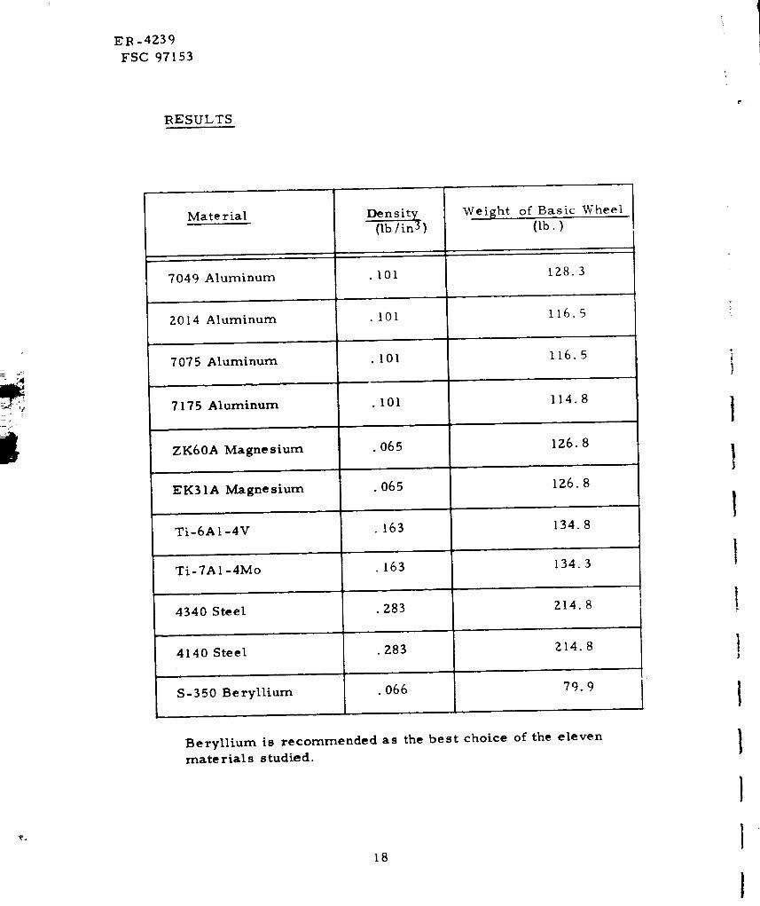
RESULTS
Mate rial
7049 Aluminum
of Basic Wheel
(Ib7')'
128.3
Weight
(Ib/in3)
• I01
_ , ,, m
• 101 116.52014 Aluminum
7075 Aluminum .101 116.5
L,
7175 Aluminum . I01 114.8
ZK60A Magnesium .065 IZ6.8
EK31A Magnesium .065 I26.8
Ti-6AI-4V . 163 134.8
Ti-7AI-4Mo . 163 134.3
4340 Steel .283 214.8
4140 Steel .283 214.8
S-350 Beryllium .066 79.9
Beryllium is recommended as the best choice of the eleven
materials studied•
18
I
l
l
t
I
l
I
!
!
I
I
I
I
I
I
I
ER -4239.
FSC 97153
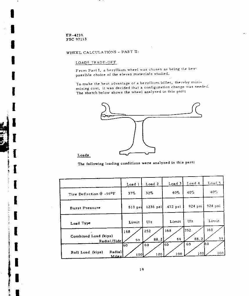
WHEEL CALCULATIONS - PART If:
LOADS r__ ADK-OFF
From Part I, a beryllium wheel was chosen as being the best
possible choice of the eleven materials studied.
To make the best advantage of a beryllium billet, thereby nnini-
miz_ng cost, it was decided that a configuration change was needed.
The sketch below shows the wheel analyzed in this part:
Loads
The following loading conditions were analyzed in this part:
I
I
!
!
I
I
Tire Deflection @ -55°F
Burst Pressure
Load Type
Combined Load (kips)
Radial/Sidem m ,|,
Roll Load (kips) RadialMile_
Load 1n
Load 3Load Z Load 4 Load 5.... .
37% 32% 40_o 40,% 40%
510 psi
Limit
lZ36 psi
Ult
472 psi
Limit
/ 1oo
924 psi
Ult
1(30
924 psi
Limit
19

ER -4Z;9
FSC 97153
The philosophy of designing with these loads was to compare the weight
difference between the ultimate failure loading and the design limit load-
ing. The ultimate loads are designed to the ultimate material strength
and the limit loads are designed to the material yield strength.
Analysis
As in P_,rt I, the analysis includes ring, cylinder, and plate methods; the
results are shown in the Table VI below:
TAB LE VI
THICKNESSES AT VARIOUS LOCATIONS
,i
A
B
C
D
E
F
"G
H
I
.r
B
Load 1 Load 2 Load 3 Load 4 Load 5
.450 .631 .430 .546 .546
.360 .505 .344 •437 •437
• 500 •897 .444 .699 .699
• 395 .637 .351 .482 •482
• 850 1.100 .850 1•100 1.100,L, , • ,q
• 680 1.030 .640 .860 .640
.894 .934 •894 .934 .894
1.556 1•631 1.556 1.631 1.556
.738 .965 .738 .965 .738
.512 .690 ,512 .690 .512.o
2O
I
I
I
I
t
i
I
I
I
II

II
III
I
I
I
[
f
[
[
!,p+
[
!
III
ER-4_39
FSC 97153
RESULTS:
Load Wheel Weight*
1 70. 4 lbs.
2 91.6 lbs.
3 68.6 !bs.
4 84. 7 lbs.
5 77.2 lbs.
*The weights given do not include the bearings.
Loading philosophy number 3 gives the lightest wheel desigp.
This philosophy suggests designing a wheel to a 40% deflection,
aburst pressure 1-112 times the tire bottoming pressure, and
the limit combined load.
21
ER-4Z39
FSC 97153
REFERENCES
I °
_0
,
Roark, R. J. "Formulas for Stress and Strain", McGraw-Hill
Book Company, 1965 Table Mill - 30.
Roark, R. J. "Formulas for Stress and Strain", McGraw-Hill
Book Company, 1965, Page Z42.
The Timken Roller Bearing Company, "The T[mken Fngineering
Journal", 1967.
ZZ
1
1
I
1
I
1
I
1
I
