14433_09
TRANSCRIPT
7/27/2019 14433_09
http://slidepdf.com/reader/full/1443309 1/17
9
Grinding
1.0 THE GRINDING PROCESS
The scope of this chapter is limited. Grinding is by itself a skilled
or semiskilled craft. The intent is not to teach how to grind a ceramic part.
In-stead, the intent is to describe the process and offer some insight about
how this affects the ceramic.
Ceramics are usually ground with bonded-diamond abrasives.
There are two types of bonds in common use, metal and resinoid. Metal is
rougher and lasts longer. Resinoid is gentler and wears out faster. Always
use resinoid for finish grinding of fine-grained, dense ceramics as there is
less surface damage to the part.
Tool Type and Grit Size
There are two types of metal-bonded, diamond-cutting tools. The
sintered-powder, metallurgical type with included diamond grit and the
surface bonded type with electroplated Ni on sedimented diamond grit. Thelatter is common in metallographic grinding and polishing. The powder-
metal, bonded type is more common in the machine shop and is used for
316

7/27/2019 14433_09
http://slidepdf.com/reader/full/1443309 2/17
Grinding 317
percision shaping of a part. Resin-bonded and diamond-bonded cutting tools
also come in these two forms for similar uses. Abrasive points protrude from the
surface of the grinding wheel, as schematically shown in Figure 9.1.
Figure 9.1: The Grinding Process. Abrasives damage the ceramic surfaceto an appreciable depth. Rubbing of the wheel on the surface can cause
heating.
Grinding is a scratching process, leaving jagged scratch roots and
sub surface cracks. In Figure 9.1, not all the abrasive grains stick out from
the wheel surface the same distance, so the longest grains do most of thegrinding. Try polishing a finely ground surface. One will observe resulting
deep scratches on the surface. Grinding also leaves residual stresses in the
ceramic surface and a considerable amount of plastic deformation.1
Grit size is a factor when grinding ceramics. Finer grit leaves
smaller scratches and lower residual stresses as long as the grinding wheel
is free cutting. The down feed has to be less than the distance of the
protruding diamond points from the surface. Wheels will dull with use andhave to be dressed to free up a fresh cutting surface. Since these are
diamond wheels and are expensive, there is a reticence to dressing the
wheel and it is often abused when dull. Dull wheel surfaces rub and can
raise the interfacial temperature even to the point where the part could
fracture. In Figure 9.1, rubbing is shown to the right of the contact area.
Pullouts leave the resin bond in contact with the work piece, generating
Abrasive
Cracks
ShatteringBond
Rubbing
Workpiece
7/27/2019 14433_09
http://slidepdf.com/reader/full/1443309 3/17
318 Ceramic Technology and Processing
heat but without any cutting. There is proportionally less cutting and
proportionally more rubbing with a finer grit wheel. There is then a
practical lower limit to the grit size that usually is 220-325 grit.
Another limitation for most shop surface grinders is a minimum
down feed of 0.0001inches; this is not too precise especially after adding
in all of the machine tool compliance. With a small grit size, the distance
the grain protrudes is of the same order as the down feed, jamming the
wheel surface against the work piece. The modulus of many ceramics is
about 30-60x106 psi while the modulus of phenolic resins is about 1x10⁶
psi. Forces between the cutting point and the ceramic surface can push the point up into the wheel surface either elastically or by deformation of the
bond. All of this is why there is a practical lower limit on the grain size that
is effective. When one needs a finer surface, switch to lapping or polishing
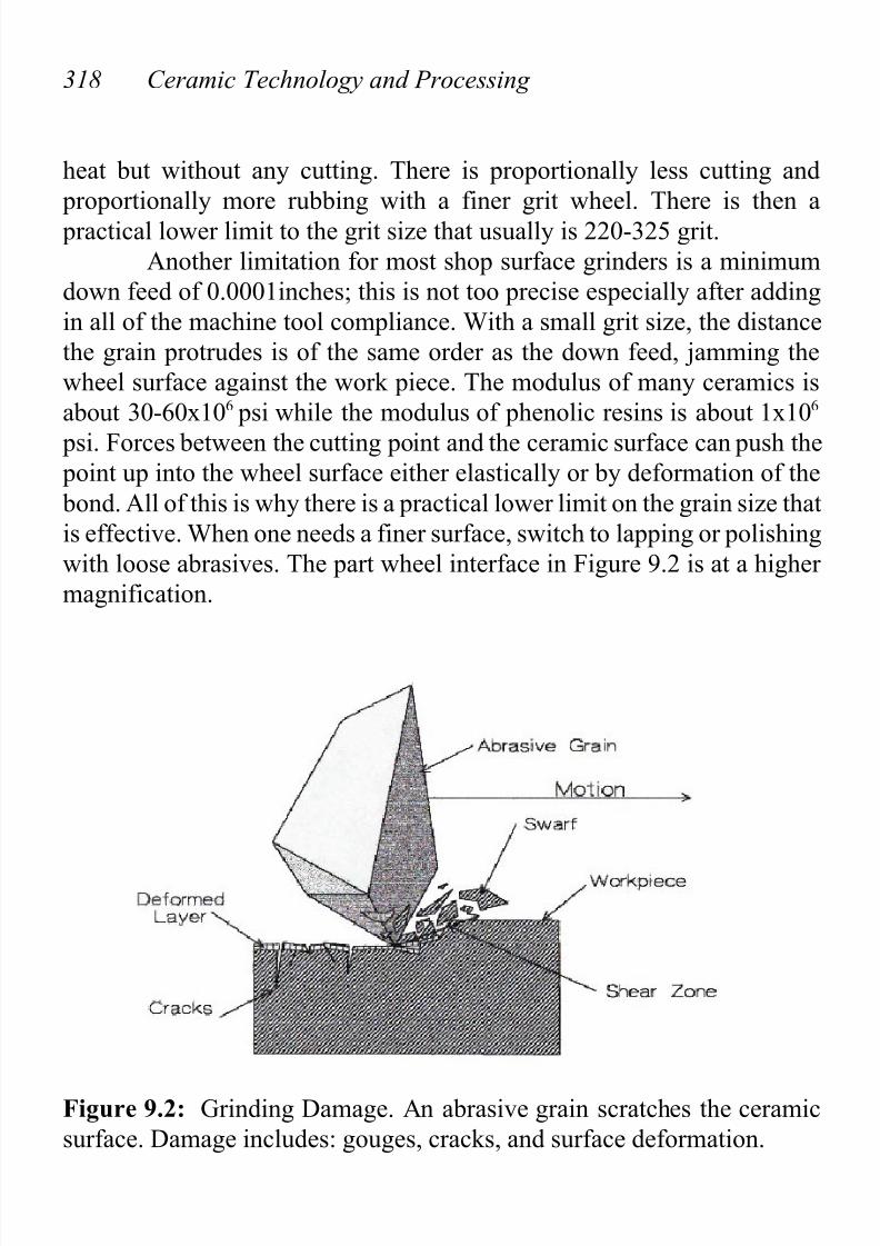
with loose abrasives. The part wheel interface in Figure 9.2 is at a higher
magnification.
Figure 9.2: Grinding Damage. An abrasive grain scratches the ceramic
surface. Damage includes: gouges, cracks, and surface deformation.

7/27/2019 14433_09
http://slidepdf.com/reader/full/1443309 4/17
Grinding 319
The above figure shows an abrasive grain scratching the ceramic
surface. This leaves damage in the ceramic, including gouges, cracks, and
a deformed surface layer. The grain creates a shearing zone in front of the
cutting tip. Fracture occurs in this shearing zone, removing material.
Surface Damage
The grinding process damages the ceramic surface. Scratches,
because of their shape, act as stress risers. Sub surface cracks and residualstresses weaken the ceramic. Two cases are illustrative, lowering the
modulus of rupture and lowering the impact strength.
Modulus of Rupture
This example is taken from work on high purity, hot pressed
alumina, fully dense, and with an average grain size of three µm.2Chemically polishing alumina with a borax fusion allows removal of the
damaged layers. Figure 9.3 illustrates the solution rate of strength vs. depth
of damage.
Strength increases as material dissolves off the damaged surface,
from 72,000 psi to 95,000 psi over a depth of five µm. This depth is also
about the size of the largest grains in the microstructure. This leads to the
unproven but likely conclusion that the damage is blocked at the grain boundaries.
Impact Strength 3
Using the same type of ceramic as in the preceding section and
varying the hot pressing temperature results in a range of grain sizes. All
of the specimens were fully dense. With the discs supported by an annular knife edge around the edge, a half-inch steel ball bearing was dropped onto
the center of each disc at a variety of heights. Figure 9.4 illustrates the
results.

7/27/2019 14433_09
http://slidepdf.com/reader/full/1443309 5/17
320 Ceramic Technology and Processing
Figure 9.3: Strength with Distance from the Surface. Strength increases
as the surface damage is dissolved away.
There are three important observations in Figure 9.4. Impact
strength decreases markedly as one reduces the hot pressing temperature,
coarser grit grinding lowers the impact strength, and annealing at 1300 °C
removes the grinding damage. (By way of explanation, the tools were not
available in the lab to measure the grain submicron size, so temperature
was the criterion by default.) Annealing is not a common practice for fine-grained, dense, ceramic parts. Maybe it should be tried more often, unless
this results in bloating.

7/27/2019 14433_09
http://slidepdf.com/reader/full/1443309 6/17
Grinding 321
Figure 9.4: Impact Strength/ Microstructure. Impact strength is
substantially reduced with lower hot pressing temperatures and larger gritgrinding wheels. Damage can be removed by annealing.
2.0 GRINDING SHOPS
There are three-setup, grinding choices: another department in the
institution, a setup in the ceramic lab, and outside sources. It is well worth
the time to consider these alternatives.

7/27/2019 14433_09
http://slidepdf.com/reader/full/1443309 7/17
322 Ceramic Technology and Processing
Another Department
Machine shops in the institution are usually in another department,
which have their own priorities. While also doing work for production
departments, lab work is at the bottom of the list, and sometimes for all
practical purposes, not even on the list. The process for making parts in the
lab is sequential: processing powders, forming, sintering, and shaping. Each
of these steps may require machine shop services. Consider the worst
scenario that one may encounter. For example, a filter may need to be
adapted for powder processing, a die may be needed for pressing the part,an end seal may be required for atmosphere sintering, and test specimens
have to be ground for measurements. With a four-week hiatus between each
step due to machine shop scheduling, it will take too long to get the
experiment completed. The author retracts an earlier statement; this is not
the worst scenario as a four-week queue is quite timely for such jobs.
Availability for machine work varies depending on the location in
question. Generally, place the choice of an inside department on the bottomof one's list.
Setting Up Grinding in the Ceramic Department
When under control of the lab, priorities are set internally, whichcan be a great relief. However, there is the problem of getting the necessary
skills, and this can be a sizable obstacle. When the work in question is
repetitive, such as grinding test bars, the level of skill is manageable. A
comprehensive grinding shop requires a lot of expensive equipment and
knowhow. With operations going broke, both equipment and skilled people
are sometimes available. This will cut the lead time, cost, and acquisition
of skills. There is also the question of facility utilization. It will take muchwork to fill the capacity of a comprehensive shop. When these requirements
are well satisfied, an internal machine shop could well be the preferred
choice.
7/27/2019 14433_09
http://slidepdf.com/reader/full/1443309 8/17
Grinding 323
Outside Contractors
One can contract work to a variety of preexisting machine shops
that also machine ceramics; these machine shops do advertise.4 Metal
working shops are plentiful. This is advantageous as skills or capabilities
can be selected; there are very talented people who will be delighted to do
business. Another big advantage is that shops do not get paid until
completion of the work and to specification. It is surprising how efficiency
is promoted when money is involved. Perhaps, the main virtues of contracting with outside shops are the skills, experience, and delivery time.
For such a contract, one recommends establishing a good rapport with a
free exchange of information.
3.0 TYPES OF GRINDING
There is no intent to make this section comprehensive, as that is
beyond the scope of this discussion. The intent is for general familiarization
and some specialized comments that may be helpful. First under
consideration will be a summary of grinding methods.
Grinding Methods
There are many types of grinding machine operations. The most
common grinding methods for ceramics are as follows: surface, cylindrical,
cutoff, universal, belt, and lap grinding. There are a variety of attachmentsthat can be added to the grinding machine for grinding, such as IDs, faces,
slots, holes, and chamfers; these will be briefly discussed.
7/27/2019 14433_09
http://slidepdf.com/reader/full/1443309 9/17
324 Ceramic Technology and Processing
Sur face Grinding
These machines have three slides: vertical, cross, and lengthwise.
There are several ways to secure the parts that need to be ground. Magnetic
chucks are useful but if the ceramic is not magnetic, one will need to glue
the parts to a steel plate that is ground flat and parallel. Hot melt adhesives
have excellent holding power and are available as sticks at any hardware
store. Place the ground steel plate on a hot plate and rub the stick to melt
the adhesive onto the surface. Preheat the parts on the hot plate and pressthem onto the adhesive with a twisting motion to seat them snug. As
everything is blistering hot, use a tool. After grinding, reheat the assembly
and remove the part. Again use a tool to prevent burns. The adhesive is
soluble in trichloroethylene, which is a safew, non ignitable solvent.
Trichloroethylene is somewhat toxic so one should use a hood or vent to
prevent vapor inhalation. Waxes are commonly used for cementing parts,
but waxes are not as good as hot melt adhesives for securing the part. Withwaxes, the part may come loose with resulting damage.
Another way to mount the parts is with steel blocks placed on the
sides and held in place with the magnetic chuck. These can come loose, so
care is required for safety.
One usually uses coolants when grinding ceramics. The supplier of
the grinding wheels will recommend the coolant suitable for this
application. The coolant is held in a sump that has a baffle, allowing theswarf to settle out. It is pumped with a nozzle directly onto the sample
surface just in front of the wheel contact. Replace the coolant and clean out
the sump regularly, depending upon the amount of use.
There are a variety of grinding wheel sizes and shapes, each of
which is preferred for the job in hand. Besides configuration, the wheel has
specifications on grit size, bond, and concentration. One uses coarse grits,
such as 120 size grits, to remove most of the stock. One uses finer sizes,such as 220-325, for finishing. For fine-grained, dense ceramics, the
preferred bond is resinoid. Coarse, friable ceramics, such as some
refractories, are so abrasive that a metal bond is necessary because of its
better wear resistance. These often use grit sizes on the coarser end.
There are two principle types of diamond: natural and synthetic.
Rough grinding applications usually use natural, as it is more durable.

7/27/2019 14433_09
http://slidepdf.com/reader/full/1443309 10/17
Grinding 325
Synthetic diamond grit is almost exclusively used for fine ceramics as it is
more friable and freer cutting. It is available in a few grades based on
friability. Additionally, synthetic is quite a bit less expensive than natural
diamond.
Concentration numbers range from 50% to 100% representing the
amount of diamond in the bond, with 100% being the maximum amount of
diamond that can be successfully incorporated. Fine ceramics use 100%
concentration. Figure 9.5 is of a surface grinder designed especially for
ceramics.
Figure 9.5: Surface Grinder. Grinding machines should be rigid and
dampen vibrations. (Courtesy of Chand Kare)

7/27/2019 14433_09
http://slidepdf.com/reader/full/1443309 11/17
326 Ceramic Technology and Processing
The principle differences between this machine tool and a metal
working machine pertain to the parameters relevant to grinding ceramics.
These are CNC controlled and include wheel speed, table motions, depth
of cut, and coolant flow.
Ceramics are more sensitive to surface damage than metals because
ceramics are brittle while metals are usually ductile. Additionally, almost
all ceramics are thermal insulators whereas almost all metals are thermal
conductors. This results in the contact surface temperature, for a ceramic
grinding, running hotter than for a metal. The machine, in Figure 9.5, has
a cast iron base that is more rigid than a weldment structure. Table motioncan be either servomotor driven or the more conventional hydraulic system.
Grinding wheels are a critical part of the grinding process. One important
wheel factor is the distribution of abrasives in the wheel bond. It turns out
that it is difficult to evenly disperse a coarse-grained material in a fine-
grained, metal, or polymer powder. The two materials tend to segregate
when handled.5
The coolant is selected and filtered for the particular ceramic beingground. Now, how are all these parameters chosen for a particular
situation? Part of the answer is by experience and part by measuring the
grindability. With grinding metals the "G" ratio is often used. This is an
efficiency factor relating to the ratio of wheel wear to the amount of metal
removed. However, for ceramics, the "G" ratio is so high due to the use of
diamond wheels that it is not useful in this case. Instead, one way is to
measure a grindablity factor. This factor relates the material removal rateto the wheel speed and the normal force between the abrasive tool and the
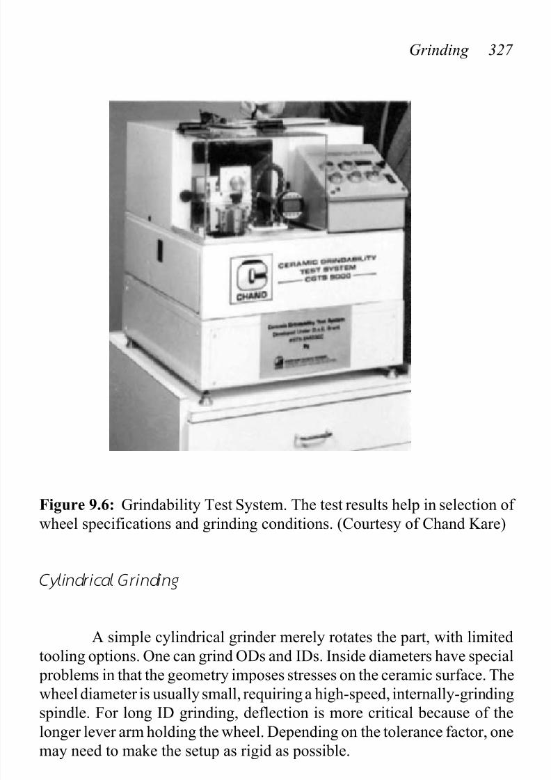
work piece. Figure 9.6 illustrates this test stand.
Testing proceeds by forcing the end of a standard (3x4x45 mm) test
bar against a diamond-grit-coated belt with a coolant. Adjustable weights
determine the normal force. Use a fresh position on the belt for each
measurement. Belt speed is adjustable. One measures the change in length
of the test bar with time. A general guideline is that with low grindabilityceramics, grinding becomes more difficult, advising slower wheel speeds,
less down feed, free cutting wheel specifications, ample coolant of the
appropriate type, and slower transverse table motion. In other words, take
it easy.
7/27/2019 14433_09
http://slidepdf.com/reader/full/1443309 12/17
Grinding 327
Figure 9.6: Grindability Test System. The test results help in selection of
wheel specifications and grinding conditions. (Courtesy of Chand Kare)
Cylindrical Grinding
A simple cylindrical grinder merely rotates the part, with limited
tooling options. One can grind ODs and IDs. Inside diameters have special
problems in that the geometry imposes stresses on the ceramic surface. Thewheel diameter is usually small, requiring a high-speed, internally-grinding
spindle. For long ID grinding, deflection is more critical because of the
longer lever arm holding the wheel. Depending on the tolerance factor, one
may need to make the setup as rigid as possible.

7/27/2019 14433_09
http://slidepdf.com/reader/full/1443309 13/17
328 Ceramic Technology and Processing
CutOff
To minimize the volume of removable material and to increase the
cutting speed, the diamond blades for cutoff purposes are usually thin. The
blade thickness for lab use is often 0.035 inches. Unit pressures are high,
making resin bonds short lived. One uses resin bonds to minimize damage
to the ceramic, but ordinarily one uses metal bonds. Only the rim of the disc
contains the diamond abrasive that is easily damaged when bent or when
a piece breaks out. The diamond-containing rim of the blade is wider than
the steel disc, providing clearance so that the disc clears the sides of the cutin the ceramic. When the cutoff blade enters the workpiece at an angle, it
is deflected down the slope and the steel disc will rub. Also, the side of the
diamond-containing rim will rub and wear. When the set of the rim is gone,
the blade will not clear the sides of the cut and for all practical purposes the
blade will be prematurely worn out. Encounter between the blade and
ceramic surface should be at 90 degrees, and when it is not, a small notch
should be cut where the blade is to enter the work so that it will not wander off square.
One can use cutoff blades on a surface grinder or on a cutoff
machine. Many lab machines use an 8-inch diameter blade. On the surface
grinder, one can gang up the blades with spacers between each blade. This
is especially useful when grinding many identical parts, like test bars.
These discs are smaller, where 4-inch D and 0.020-inch thickness is
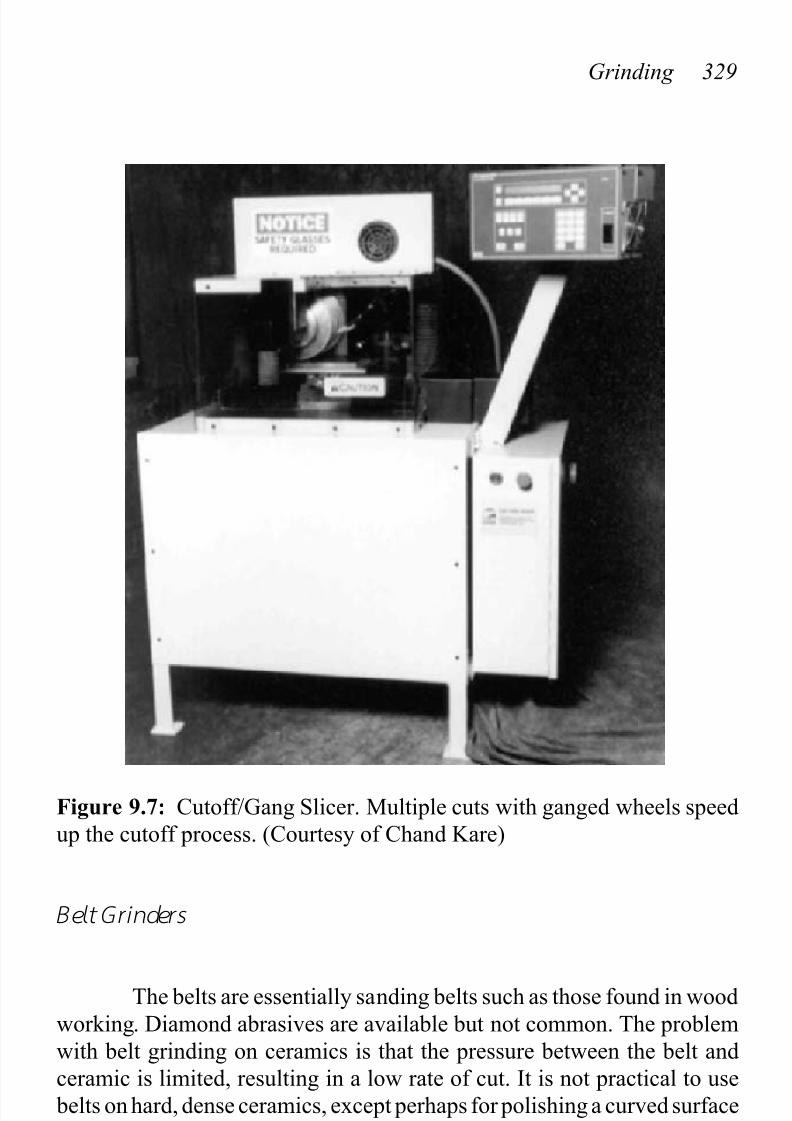
common.Figure 9.7 is of a CNC-controlled, cutoff machine that either uses
single or ganged cutoff blades with controlled wheel speed and feed rate.
Universal Gr inders
These are versatile grinding machines that have more than onespindle and the capability of multiple setups. These machines are very
expensive and not commonly found in the lab. One may need such
machines for some types of complicated or high precision work. Some
manufacturers include air bearings and vibration absorbing bases with
multiple (3) spindles.
7/27/2019 14433_09
http://slidepdf.com/reader/full/1443309 14/17
Grinding 329
Figure 9.7: Cutoff/Gang Slicer. Multiple cuts with ganged wheels speed
up the cutoff process. (Courtesy of Chand Kare)
Belt Grinders
The belts are essentially sanding belts such as those found in wood
working. Diamond abrasives are available but not common. The problem
with belt grinding on ceramics is that the pressure between the belt and
ceramic is limited, resulting in a low rate of cut. It is not practical to use
belts on hard, dense ceramics, except perhaps for polishing a curved surface
where the belt conforms the contour.
7/27/2019 14433_09
http://slidepdf.com/reader/full/1443309 15/17
330 Ceramic Technology and Processing
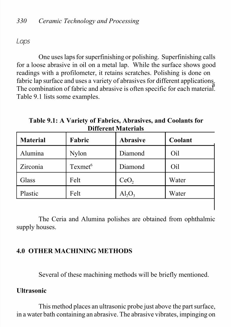
Laps
One uses laps for superfinishing or polishing. Superfinishing callsfor a loose abrasive in oil on a metal lap. While the surface shows good
readings with a profilometer, it retains scratches. Polishing is done on
afabric lap surface and uses a variety of abrasives for different applications.
The combination of fabric and abrasive is often specific for each material.
Table 9.1 lists some examples.
Table 9.1: A Variety of Fabrics, Abrasives, and Coolants for
Different Materials
Material Fabric Abrasive Coolant
Alumina Nylon Diamond Oil
Zirconia Texmet6 Diamond Oil
Glass Felt CeO2 Water
Plastic Felt Al2O3 Water
The Ceria and Alumina polishes are obtained from ophthalmic
supply houses.
4.0 OTHER MACHINING METHODS
Several of these machining methods will be briefly mentioned.
Ultrasonic
This method places an ultrasonic probe just above the part surface,
in a water bath containing an abrasive. The abrasive vibrates, impinging on

7/27/2019 14433_09
http://slidepdf.com/reader/full/1443309 16/17
Grinding 331
the surface and nibbling it away. Hole shape is that of the tool, making this
method especially useful for odd shapes. Tool material is often a soft metal
(often copper) that resists abrasion. Soft metals tend to smear rather than
cut and can be durable under these conditions.
Electro Discharge Machining (EDM)
Tooling for EDM looks similar to that used for ultrasonic in that
there is a shaped probe just above the surface of the ceramic. With theceramic grounded and the probe charged, an electric spark erodes the
ceramic surface. For this to happen, the ceramic has to be an electrical
conductor, placing a restriction on where the technique is applicable.
Check L ist, Grinding
• Grinding Shop
Departmental
In the lab
Outside sources
• Grinding Method
Surface
CylindricalCutoff
Universal
Belts
Laps
• Other Methods
Ultrasonic
EDM

7/27/2019 14433_09
http://slidepdf.com/reader/full/1443309 17/17
332 Ceramic Technology and Processing
REFERENCES
1. D. Johnson-Walls, A. G. Evans, D. B. Marshall, and M. R. James,"Residual Stresses in Machined Ceramic Surfaces," J. Am. Ceramics Soc.
69[1] 44-47 (1986).
2. A. G. King, "Chemical Polish and Strength of Alumina," Materials
Science Research Vol.3, (Plenum Press, 1966), pp. 529-38.
3. Alan G. King and W. M. Wheildon. Ceramics in Machining Processes.
New York: Academic Press, 1966, p 63.
4. American Ceramic Society Bulletin, Westerville, Ohio.
5. Roland H. Chand, Personal Communication.6. Buehler trade name.