143 tan aupec01paper revised
TRANSCRIPT
8/12/2019 143 Tan AUPEC01paper Revised
http://slidepdf.com/reader/full/143-tan-aupec01paper-revised 1/6
Mechanical Sensorless Robust Control of Wind Turbine
Driven Permanent Magnet Synchronous Generator
For Maximum Power Operation
Kelvin Tan Syed Islam
Australian Cooperative Research Centre for Renewable Energy LtdCentre of Renewable Energy and Sustainable Technologies Australia (CRESTA)
Curtin University of Technology, WA
Abstract: This paper proposes a prototype version of the control strategy of a permanent magnet synchronousgenerator for maximum power operation without mechanical sensors. This approach is based on the calculated
maximum rotor power vs. alternator frequency curve, and calculated maximum rotor power vs. rectified DC
voltage curve to obtain a maximum power output at a certain wind speed. This control allowed the permanentmagnet gener ator to operate at an optimal speed for a given wind speed. To show the feasibility of this
mechanical sensorless control strategy for maximum power estimation, a simple mathematical model of a
variable speed wind energy conversion system – permanent magnet generator was developed. The mathematicalmodel was used to calculate the response of the wind energy conversion and to determine the maximum power
operating point. This paper also describes a theoretical aspect of this method. Digital simulation of the system
was performed to illustrate the advantages of this control strategy.
1. INTRODUCTION
Optimum wind energy extraction is achieved byrunning the wind turbine generator (WTG) invariable-speed variable-frequency mode. The rotor
speed is allowed to vary in sympathy with the wind
speed, by maintaining the tip speed ratio to thevalue that maximizes aerodynamic efficiency. In
order to achieve this, the permanent magnet
synchronous generator (PMSG) load line should bematched very closely to the maximum power line
of the wind turbine generator. In such a case, agood matching exists between the generator and the
load for the best performance of the system and
maximum utilization of the wind driven PMSG.However, the recent advancements in power
electronics and control strategies have made it
possible to regulate the voltage of the PMSG in
many different ways. When the generator torqueline can be controlled; the generator loading of the
turbine can be made to follow the desired locussuch as the optimum shaft power locus. In the
existing controller for the maximum power
extraction, most designed controllers use ananemometer to measure wind speed for deriving the
demand shaft speed [1]. In most cases, one
anemometer reading could not provide adequate
information. The required information would needto be provided through a number of anemometers at
some distance away from and surrounding the windturbine. Sensors measurement of mechanical
quantities such as shaft torque and rotation speed
may be required. These sensors increase the cost
and reduce the reliability of the overall system. To
achieve optimal power output, a sensorless schemewill be proposed for extracting desired output power from the permanent magnet generator over a
wide range of wind speeds. The proposed system
will increase the overall output of the generationsystem with a minimal increase in controller
complexity.
2.MATHEMATICAL MODELING OF THE
ELEMENTS OF THE WIND ENERGY
CONVERSION SYSTEM
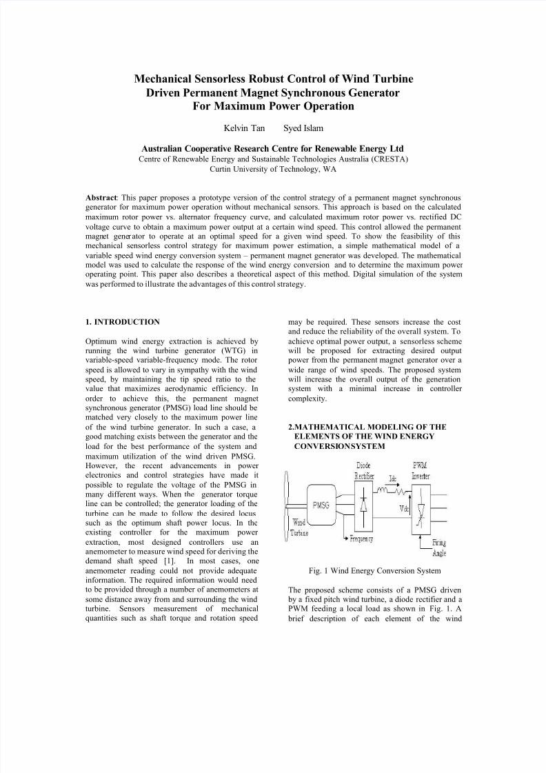
Fig. 1 Wind Energy Conversion System
The proposed scheme consists of a PMSG driven by a fixed pitch wind turbine, a diode rectifier and aPWM feeding a local load as shown in Fig. 1. A
brief description of each element of the wind

8/12/2019 143 Tan AUPEC01paper Revised
http://slidepdf.com/reader/full/143-tan-aupec01paper-revised 2/6
energy conversion system is shown in this section.
These models are expressed in the d-q rotor
reference frame. This eliminates all time-varyinginductances by referring the stator and rotor
variables to a frame of references, which rotateswith rotor
2.1 Power from wind turbine
Fig. 2 Power Coefficient vs. Tip Speed Ratio
with β=0
The output mechanical power of the wind turbine
may be calculated from the following equation[1]:
Watts3
wAUC2
1mP ρρ= (1)
CP is the power coefficient, which is a function of
tip speed ratio λ and blade angle β. Thisrelationship is usually provided by the
manufacturer in the form of a set of non-dimensional curves. The power coefficient curve CP for the wind turbine used in this study is shown inFig. 2. The tip speed ratio is given by:
wU
r r ωλ = (2)
Where
r = radius of the rotor [m]
ρ = air density [Kgm-3
]
A = wind turbine rotor swept area [m2]
Uw = wind speed [m/s]
ωr = mechanical angular velocity of thegenerator
For a variable speed wind turbine with a pitch
control mechanism that alters the effective rotor
dynamic efficiency, optimum power can easily beobtained using appropriate control. However, fixed
pitch wind turbine has been used in this prototype
wind energy conversion scheme (WECS).
2.2 Permanent magnet synchronous generator
model
Model for the power producing capabilities of awind turbine has been previously developed [2, 3].The outer-rotor PMSG described in the paper[4] isused in this WECS mathematical model. The
PMSG dynamic equations are expressed in the d-q
reference frame, which eliminate all time-varyinginductances by referring the stator and rotor
variables to a frame of references, which rotateswith the rotor. The model of electrical dynamics in
terms of voltages and current can be given as[3]:
mr di
dLr q)iqL(R qv λωωρ +−+−= (3)
qiqLr d)i
dL(R
dv ωρ ++−= (4)
Where
R, L= Machine resistance and inductance per phasevd, vq = 2-axis machine voltages
id, iq = 2-axis machine currents
The above equations are derived assuming that the
q-axis is aligned with the stator terminal voltage phasor (i.e.Vd=0). The expression for theelectromagnetic torque in the rotor is written as:
( )[ ]qmdqqde iiiLL2
P
2
3T λ−−
= (5)
Where
P = number of poles of the PMSGT e = electrical torque from the generator
λm =amplitude of the flux linkages established a
permanent magnet
The relationship between the angular frequency of
the stator voltage (ωr ) and the mechanical angular
velocity of the rotor (ωm) may be expressed as:
m2
pr ωω = (6)
The mathematical prediction of voltage variationwith the load current from the PMSG at six
different rotational speeds is calculated and shown
in Fig. 3. It seems that there is a good agreement between the predicted and experimental results.[4]

8/12/2019 143 Tan AUPEC01paper Revised
http://slidepdf.com/reader/full/143-tan-aupec01paper-revised 3/6
0
2000
4000
6000
8000
10000
12000
14000
16000
18000
20000
22000
0 2 0 4 0 6 0 80 100 120Frequency (Hz)
D C P o w e r ( W
Fig. 3 calculated voltage regulationof the PMSG
2.3 Uncontrolled Rectifier
As the wind speed is constantly varying, the PMSG
produces variable-voltage and variable-frequencyoutput, which cannot be fed directly to load. A 3-
phase diode rectifier, which is used to convert thevariable magnitude, variable frequency voltage at
the PMSG terminal to dc. Under the assumption
that the both commutating angle & commutatinginductance are negligible, the rectifier outputvoltages (VR ) and current (IR ) expression may be
simplified and expressed in term of the peak phase
voltage and current (fundamental component) ofthe generator [5, 6]:
dv
p
33
R V = (7)
qi
32
p
R I = (8)
The dc power available at the rectifier output is
converted to ac power using a PWM inverter. The
output of the wind turbine generator is controlled by adjusting the modulation index M of the
reference sinusoidal signal of the PWM inverter,and it ranges from 0 to 1. In order to make the
inverter of the AC-DC-AC link to track the
maximum power output from the WTG, thesensorless controller is designed to determine the
operating dc voltage of the inverter at various
speeds. This will control the pulse width of the
PWM inverter and the power transferred to the
local load indirectly by controlling the powerextracted from the WTG.
3. WIND DRIVEN PMSG CHARACTERISTICS
In the proposed sensorless scheme, the inverterinput operating voltage is determined by a
“mapping-power” technique. In this technique, the
controller does not require a mathematical model of
the system/process being controlled. However, it is
important to understand the voltage, current and power characteristics generated by the system at
various constant wind speeds. Fig. 1 shows thecomponents of a typical stand-alone wind energy
conversion system. Wind energy conversion systemis simulated using Matlab Simulink to calculate thegenerator stator frequency, dc current and voltageat the dc link at various wind speeds.
The dc power output characteristics at the dc linkare then calculated following a step change in
different operating dc voltages. The results of thecalculations are for wind speed range 3-11m/sec.
The results are shown in Fig. 4 and Fig. 5. These
form the output power curves of the PMSG atvarious constant wind speeds, the generatormaximum power curves show the different
operating dc voltages and stator frequencies over a
range of wind speeds. In order to extract the p eak power from the WTG at a given wind speed, the
WECS has to operate at the target maximum powercurve. The operating dc voltage and stator
frequency have to match closely to the maximum
power curve, as shown in Fig. 4 (maximum powervs. stator frequency) and Fig. 5 (maximum power
vs. dc voltage).
Fig. 4 Predicted characteristic
(dc power-stator frequency ) of the WECS
Fig. 5 Predicted characteristic
(dc power-dc voltage ) of the WECS
0
2000
4000
6000
8000
10000
12000
14000
16000
18000
20000
22000
0 100 200 300 400 500 600 700
DC Voltage ( V)
D C P o w e r

8/12/2019 143 Tan AUPEC01paper Revised
http://slidepdf.com/reader/full/143-tan-aupec01paper-revised 4/6
By combining the characteristics of the PMSG
which determine, dc power output at different wind
speeds, operating limit of the WECS system could be drawn in the power- frequency or power-Vdc
plane. Such system limitation is shown in Fig. 6.
Fig. 6 System limitation in the powervoltage plane
From Fig. 6, it is seen that the limitation on the left
is bounded by the minimum dc link voltage
required by the inverter. This line is due to thevoltage-current characteristic of the PMSG. At aconstant given wind speed, the PMSG is under
increasing load as the dc voltage decreases. When
the dc voltage is less then the minimum dc linkrequirement, the operating of PMSG wind turbine
is in stalled region of operation. Any decrease in
the tip speed ratio will cause a further decrease untilthe turbine stops. The upper limitation is bounded
by the rated wind speed (11m/s) and maximum power capability of the PMSG. If the maximum
power limitation of the inverter is lower than the
maximum power capability of the PMSG. Theupper limitation is bounded by inverter power
limitation. The right limitation represents the
maximum speed of the wind turbine PMSG. The
system controller is constrained to operate withinthe power limitations shown in Fig. 6. This is an
important consideration for the design of thesystem controllers.
4. DESCRIPTION OF THE CONTROLLEDWECS STRUCTURE
The block diagram shown in Fig. 7 is the
preliminary design of the sensorless WECScontrolled system. In the preliminary design stage,
the system does not include the minimum dc link
limitation, cut-in and cutout wind speed control
features. To show the feasibility of this mechanical
sensorless control strategy for maximum power
estimation, a simple mathematical model of the
proposed control system is developed. The controlsystem consists of two signal-tracking loops,
namely the “power-mapping" loop and alternatorfrequency derivative loop. The tracking signals
required for both loops are the output power fromthe WECS that is transferred to the dc link andPMSG stator frequency.
It is recognized that the inverter has the flexibility
to operate over a wide range of dc input voltages.At a given wind speed, the output dc link power is
used to estimate the optimal dc operating voltagefrom the "power-mapping" maximum power vs. dc
voltage curve shown in Fig. 5. Due to the
sensitivity of Pdc to the changes in Vdc for thePMSG, the Pdc and Vdc will continue to increase ordecrease till the intersection of Pdc and Vdc at the
maximum power for the given wind speed. The
stator frequency will also be changing (increasingor decreasing) during the change of the operating
dc voltage. In the alternator frequency derivativeloop, the derivative control action provides a means
of obtaining the controller with higher sensitivity.
This derivative control responds to the rate ofchanges of the stator frequency and can produce a
significant correction to the operating dc voltage.
The gain value from frequency derivative loop will become zero when the operating dc voltage is
optimal one which leads to the maximum power
point. Using the results determined by both loops,
the controller allows the dc bus voltage to vary tothe maximum power operating point.
Fig.7 Block diagram of the sensorless WECS
controlled system
5. SIMULATION RESULTS
A mathematical simulation model of the proposed
WECS is developed. The WECS has beensimulated on a PC using Matlab Simulink software

8/12/2019 143 Tan AUPEC01paper Revised
http://slidepdf.com/reader/full/143-tan-aupec01paper-revised 5/6
Fig. 8 Simulation results depicting variation of system variables with step changes in wind velocity
and its toolbox packages. With the simulation
results, we are able to study most of the system
characteristics such as its tracking performance andits ability to recover from large disturbances. Two
case studies are considered and described as
follows:-
5.1 Case 1: Step model of wind speed
The simulation result is shown in Fig. 8. The wind
speed is shown in the form of fast step variation
(from 5 to 11m/s). It seems that with increase inwind speed, the sensorless controller increases the
operating dc voltage, which directly controls the
modulation index of the PWM inverter. This
increases the power output of the inverter and the power transferred over the dc link. Also, the power
output of the rectifier drawn from the wind drivenPMSG increases, thereby ensuring the complete
utilization of available wind energy. As shown in
Fig. 8, the change in the peak power in the dc linkfollows the wind speed profile. The peak power
shown in the Fig. 8(iii) is the actual maximum
power for each given wind speed. It is also observedthat the peaks in the error are recorded only in the
points of sudden change in the wind speed.
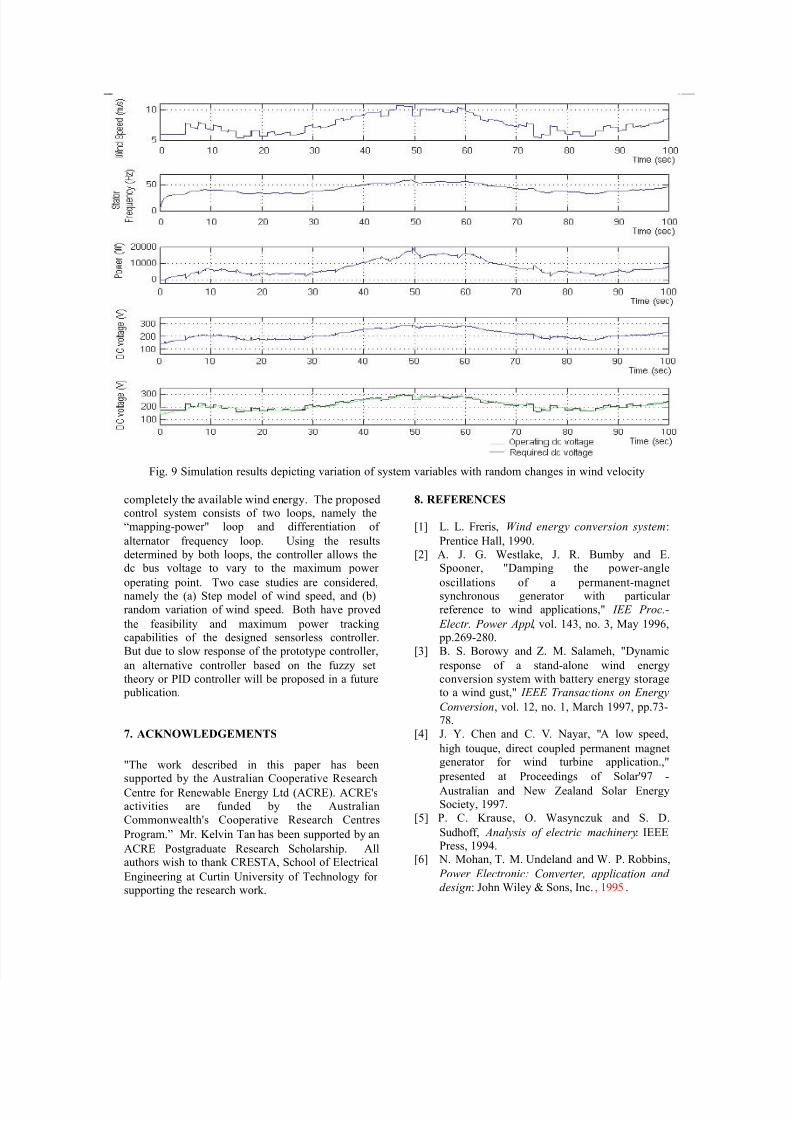
5.2 Case 2 : Random variation of wind speed
On achieving the goal of efficiently tracking the
maximum output power from the wind, the designedcontroller should respond to the wide variation of
wind speed. The variation of wind profile is shown
in Fig. 9(i). In the case when the wind is fluctuating
with a non-uniform distribution, the output powerfrom the inverter will not be smooth. From Fig.
9(iv), it is clear that that the two profiles, operating
dc voltage and required operating voltage for
maximum power, are close to each other withinalmost the whole wind variation. Therefore, the peak
power shown in Fig. 9(iii) is close to the actualmaximum power for each variation of wind speed.
On the other hand, comparing the error signal obtain
from operating dc voltage and required operatingvoltage for maximum power, there is a high value of
error signal at starting of each sudden change of
wind speed. This is due to high gain in the alternator
frequency derivative loop and slow response of thesystem. A more intelligent controller may be
required for higher tracking performance with fastresponse and robust control.
6. CONCLUSION
The paper presents modeling and simulation resultof a prototype variable speed sensorless WECS. The
variable amplitude, variable frequency voltage at the
PMSG terminals is first rectified in a diode rectifierand the dc power is transferred over the dc link to aPWM inverter feeding to a local load. A sensorless
controller is used to determine the optimal operating
dc voltage which is then used to control the ofmodulation index of the PWM inverter to utilize
8/12/2019 143 Tan AUPEC01paper Revised
http://slidepdf.com/reader/full/143-tan-aupec01paper-revised 6/6
Fig. 9 Simulation results depicting variation of system variables with random changes in wind velocity
completely the available wind energy. The proposedcontrol system consists of two loops, namely the
“mapping-power" loop and differentiation of
alternator frequency loop. Using the results
determined by both loops, the controller allows thedc bus voltage to vary to the maximum power
operating point. Two case studies are considered,namely the (a) Step model of wind speed, and (b)
random variation of wind speed. Both have proved
the feasibility and maximum power trackingcapabilities of the designed sensorless controller.
But due to slow response of the prototype controller,
an alternative controller based on the fuzzy set
theory or PID controller will be proposed in a future publication.
7. ACKNOWLEDGEMENTS
"The work described in this paper has beensupported by the Australian Cooperative Research
Centre for Renewable Energy Ltd (ACRE). ACRE'sactivities are funded by the Australian
Commonwealth's Cooperative Research Centres
Program.” Mr. Kelvin Tan has been supported by an
ACRE Postgraduate Research Scholarship. Allauthors wish to thank CRESTA, School of Electrical
Engineering at Curtin University of Technology forsupporting the research work.
8. REFERENCES
[1] L. L. Freris, Wind energy conversion system :
Prentice Hall, 1990.
[2] A. J. G. Westlake, J. R. Bumby and E.Spooner, "Damping the power-angle
oscillations of a permanent-magnetsynchronous generator with particular
reference to wind applications," IEE Proc.-
Electr. Power Appl , vol. 143, no. 3, May 1996, pp.269-280.
[3] B. S. Borowy and Z. M. Salameh, "Dynamic
response of a stand-alone wind energy
conversion system with battery energy storageto a wind gust," IEEE Transactions on Energy
Conversion, vol. 12, no. 1, March 1997, pp.73-78.
[4] J. Y. Chen and C. V. Nayar, "A low speed,
high touque, direct coupled permanent magnetgenerator for wind turbine application.,"
presented at Proceedings of Solar'97 -
Australian and New Zealand Solar EnergySociety, 1997.
[5] P. C. Krause, O. Wasynczuk and S. D.
Sudhoff, Analysis of electric machinery: IEEEPress, 1994.
[6] N. Mohan, T. M. Undeland and W. P. Robbins,
Power Electronic: Converter, application and
design: John Wiley & Sons, Inc. , 1995 .