14241 s. redwood rd., bluffdale, ut 84065 • phone 1.800 ... · install in accordance with the...
TRANSCRIPT
1 Rev.1.11
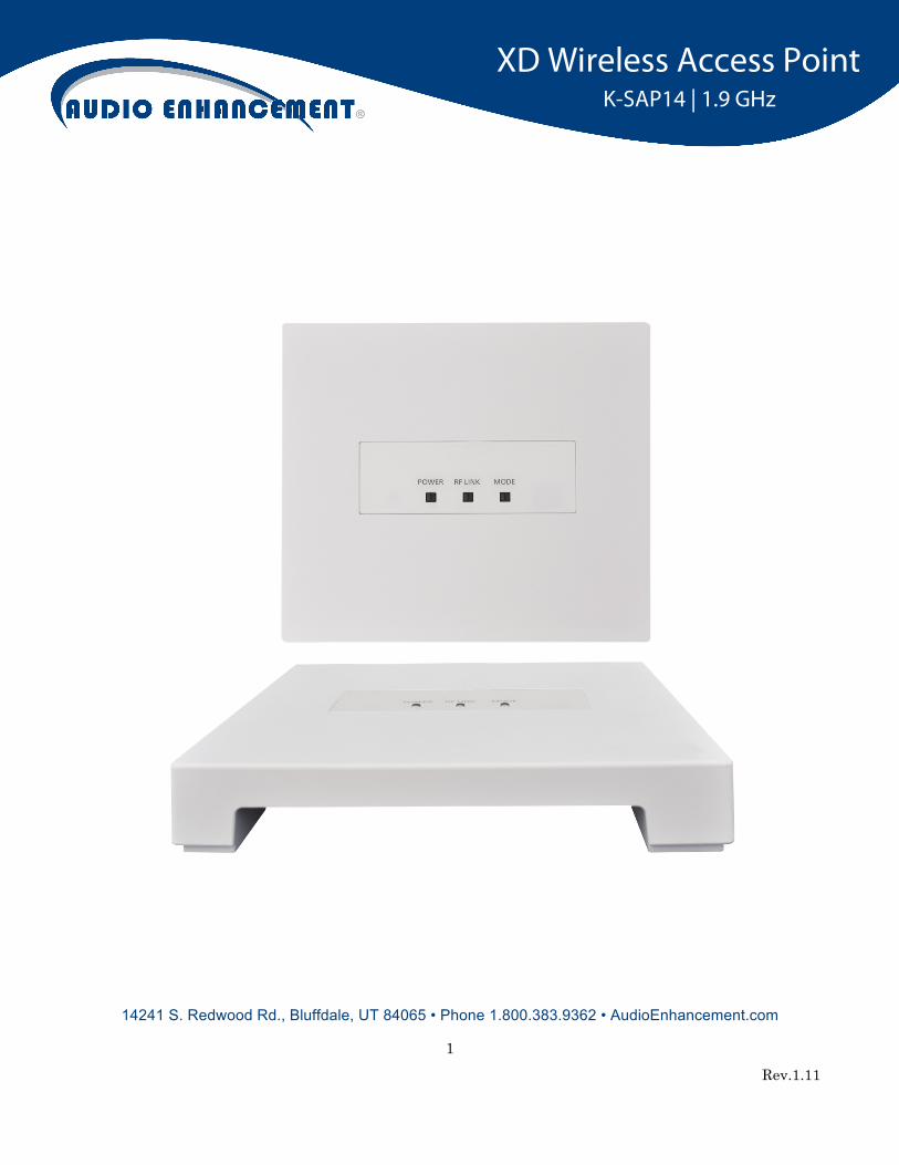
14241 S. Redwood Rd., Bluffdale, UT 84065 • Phone 1.800.383.9362 • AudioEnhancement.com
XD Wireless Access Point K-SAP14 | 1.9 GHz

2 Rev.1.11
FCC CAUTION Changes or modifications not expressly approved by the party responsible for compliance could void the
user’s authority to operate the equipment.
This device complies with part 15 of the FCC Rules. Operation is subject to the following two conditions:
(1) This device may not cause harmful interference, and (2) this device must accept any interference
received, including interference that may cause undesired operation.
Note: This equipment has been tested and found to comply with the limits for a Class A digital device,
pursuant to part 15 of the FCC Rules. These limits are designed to provide reasonable protection against
harmful interference when the equipment is operated in a commercial environment. This equipment
generates, uses, and can radiate radio frequency energy and, if not installed and used in accordance with
the instruction manual, may cause harmful interference to radio communications. Operation of this
equipment in a residential area is likely to cause harmful interference, in which case the user will be
required to correct the interference at his own expense.
Compliance with FCC requirement 15.407(c)
Data transmission is always initiated by software, which is passed down through the MAC, through the
digital and analog baseband, and finally to the RF chip. Several special packets are initiated by the MAC.
These are the only ways the digital baseband portion will turn on the RF transmitter, which it then turns off
at the end of the packet. Therefore, the transmitter will be on only while one of the aforementioned packets
is being transmitted. In other words, this device automatically discontinues transmission in case of either
absence of information to transmit or operational failure.
MEDICAL:
Consult the manufacturer of any personal medical devices, such as pacemakers, to determine if they are
adequately shielded from external RF (radio frequency) energy. The unit operates in the frequency range
of 1.92 GHz to 1.93 GHz.
Do not use the unit in health care facilities if any regulations posted in the area instruct you not to do so.
Hospitals or health care facilities may be using equipment that could be sensitive to external RF (radio
frequency) energy.
3 Rev.1.11
Radio Frequency (RF) Exposure Warning
This equipment complies with FCC radiation exposure limits set forth for an uncontrolled environment and
meets the FCC radio frequency (RF) Exposure Guidelines. This equipment should be installed and
operated keeping the radiator at least 20 cm or more away from person’s body.
Notice
FCC ID can be found on the bottom of the units.

4 Rev.1.11
Safety precautions
WARNING:
- The main plug or an appliance coupler shall remain readily operable.
- To prevent injury, this apparatus must be securely attached to the floor/wall in accordance with the
installation instructions.
- The connections should comply with local electrical code.
- The installation shall be carried out in accordance with all applicable installation rules.
- To reduce the risk of fire or electric shock, do not expose this apparatus to rain or moisture.
- The apparatus should not be exposed to dripping or splashing and that no objects filled with liquids, such
as vases, should be placed on the apparatus.
- All work related to the installation of this product should be made by qualified service personnel or
system installers.
- This product has no power switch. When turning off the power, disconnect the power supply from the
PoE device.
CAUTION:
Before attempting to connect or operate this product, please read the label on the bottom.

5 Rev.1.11
Contents
Contents ............................................................................................................................................................ 5
Important safety instructions ............................................................................................................................. 6
Major Operating Controls and Their Functions ................................................................................................. 7
Settings ............................................................................................................................................................. 9
Connections .................................................................................................................................................... 13
Precautions for Installation .............................................................................................................................. 15
Installation ....................................................................................................................................................... 16
CGI command list ........................................................................................................................................... 20
Specifications .................................................................................................................................................. 23
Accessories ..................................................................................................................................................... 23

6 Rev.1.11
Important safety instructions
1) Read these instructions.
2) Keep these instructions.
3) Heed all warnings.
4) Follow all instructions.
5) Do not use this apparatus near water.
6) Clean only with dry cloth.
7) Do not block any ventilation openings. Install in accordance with the manufacturer's instructions.
8) Do not install near any heat sources such as radiators, heat registers, stoves, or other apparatus (including
amplifiers) that produce heat.
9) Protect the power cord from being walked on or pinched, particularly at plugs, convenience receptacles, and the
point where they exit from the apparatus.
10) Only use attachments/accessories specified by the manufacturer.
11) Use only with the cart, stand, tripod, bracket, or table specified by the manufacturer, or sold with the apparatus.
When a cart is used, use caution when moving the cart/apparatus combination to avoid injury from tip-over.
12) Unplug this apparatus during lightning storms or when unused for long periods of time.
13) Refer all servicing to qualified service personnel. Servicing is required when the apparatus has been damaged
in any way, such as if a power-supply cord or plug is damaged, liquid has been spilled or objects have fallen
into the apparatus, the apparatus has been exposed to rain or moisture, does not operate normally, or has
been dropped.
7 Rev.1.11
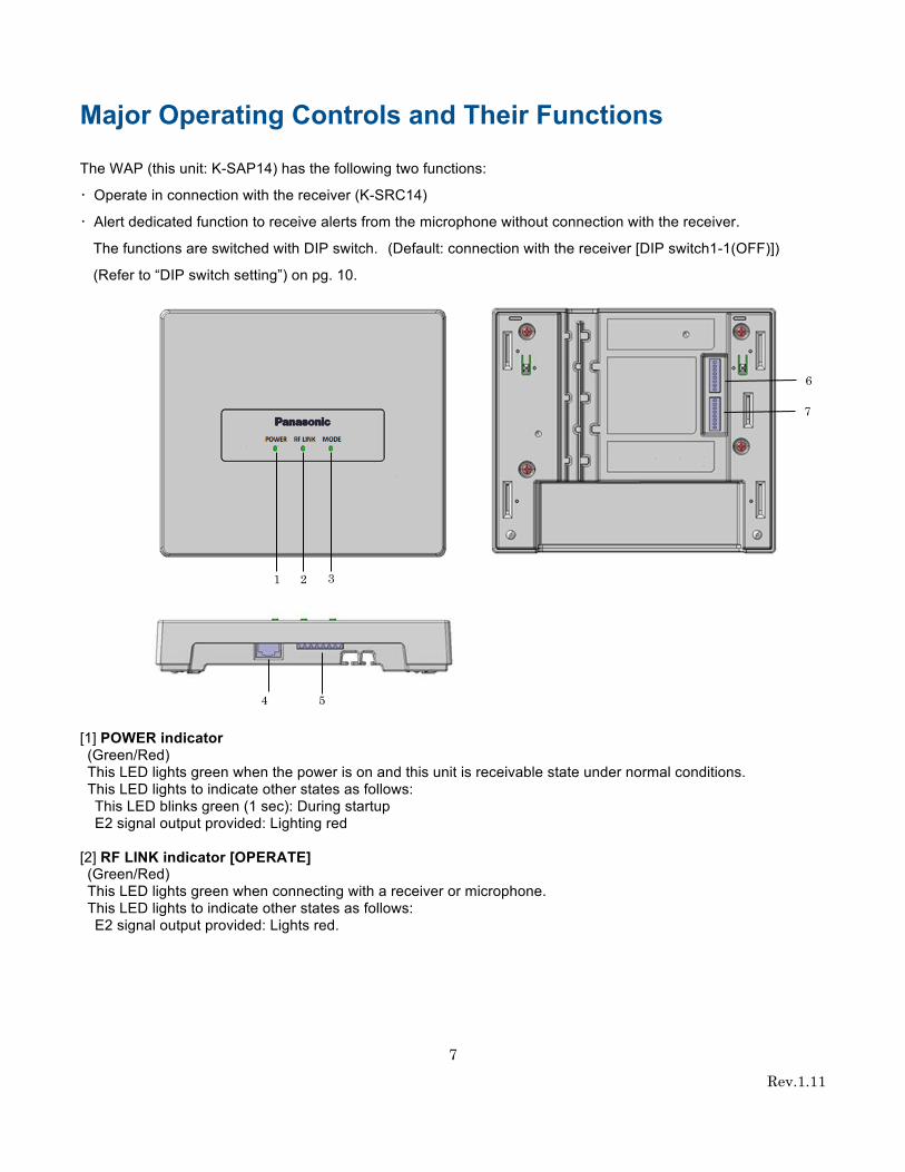
Major Operating Controls and Their Functions
The WAP (this unit: K-SAP14) has the following two functions:
・ Operate in connection with the receiver (K-SRC14)
・ Alert dedicated function to receive alerts from the microphone without connection with the receiver.
The functions are switched with DIP switch. (Default: connection with the receiver [DIP switch1-1(OFF)])
(Refer to “DIP switch setting”) on pg. 10.
[1] POWER indicator (Green/Red) This LED lights green when the power is on and this unit is receivable state under normal conditions. This LED lights to indicate other states as follows: This LED blinks green (1 sec): During startup E2 signal output provided: Lighting red
[2] RF LINK indicator [OPERATE] (Green/Red) This LED lights green when connecting with a receiver or microphone. This LED lights to indicate other states as follows: E2 signal output provided: Lights red.
4 5
6
7
2 3 1

8 Rev.1.11
[3] MODE indicator (Green/Yellow/Red) This LED blinks yellow (600 ms) during the registration process to pair a receiver.
[when receiver connection WAP (DIP switch 1-1” OFF”)] This LED lights green when this unit has been set as WAP for receiver connection. (DIP switch 1-1”OFF”) This LED lights yellow when this unit has been set as WAP for Alert ONLY WAP. (DIP switch 1-1”ON”Default) This LED lights red when there is a system error.
[4] Ethernet connector One RJ-45 type connector is used for a LAN connector. Connect to PoE networks.
[5] Control terminals (Refer to “Wiring of Euroblock connector”)
7-pin Euro blocks are used. The following terminals are equipped:
E2 CNT: Provides E2 signal output controlled by Alert Notification Button. Alert Notification Button: For input of a signal from the external Alert Notification Button.
[6] DIP switch 1
DIP switch 1-1 can switch the operation mode for function equipped in this unit. When set to ON, the WAP will work for alert only. When set to OFF, the WAP connects with a receiver.
DIP switch 1-2: Transmit power [ON(HIGH)/ /OFF(Normal)] (For Alert ONLY WAP) DIP switch1-8: Password initialization for authentication (Password to use when HEMS / VPS connection)
[7] DIP switch 2 No.1 to 7 of DIP switch 2 are used for selection of group ID. (It is used at the time of installation of WAP and a receiver.)
* DIP switch settings, is referred to only once when the power is turned on A system compliant with the 1.9 GHz band XD* standard is used so the voices of the teachers and students are heard clearly and distinctly even in open areas, and interference is minimal, resulting in stable communication. * Digital Enhanced Cordless Telecommunications
9 Rev.1.11
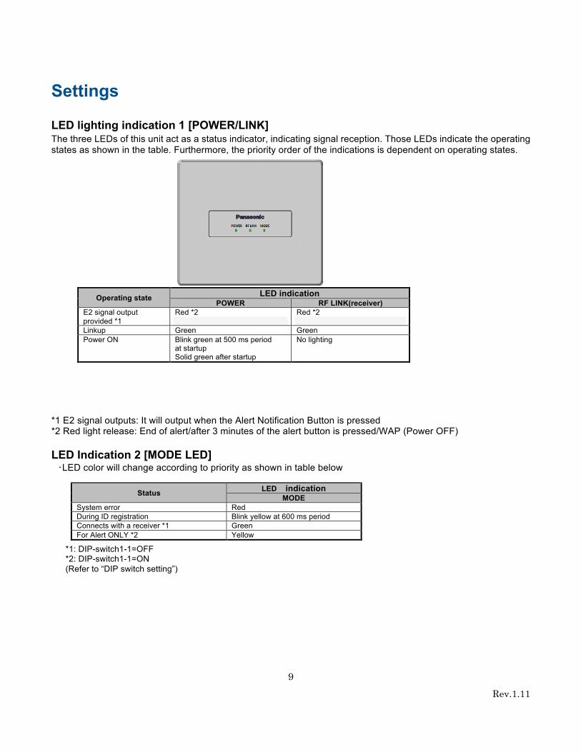
Settings
LED lighting indication 1 [POWER/LINK] The three LEDs of this unit act as a status indicator, indicating signal reception. Those LEDs indicate the operating states as shown in the table. Furthermore, the priority order of the indications is dependent on operating states.
*1 E2 signal outputs: It will output when the Alert Notification Button is pressed *2 Red light release: End of alert/after 3 minutes of the alert button is pressed/WAP (Power OFF) LED Indication 2 [MODE LED]
・LED color will change according to priority as shown in table below
*1: DIP-switch1-1=OFF *2: DIP-switch1-1=ON (Refer to “DIP switch setting”)
Operating state LED indication POWER RF LINK(receiver)
E2 signal output provided *1
Red *2
Red *2
Linkup Green Green Power ON Blink green at 500 ms period
at startup Solid green after startup
No lighting
Status LED indication MODE
System error Red During ID registration Blink yellow at 600 ms period Connects with a receiver *1 Green For Alert ONLY *2 Yellow

10 Rev.1.11
DIP switch setting
switch No Name Function OFF ON
Switch1
1 MODE ON = ALERT Selecting “For Alert ONLY” or ”For receiver
connection” 。 For receiver connection * For Alert ONLY
2 Tx Pwr Normal/Hi "For Alert ONLY" AP Tx Power settings
Low (mode1)* High (mode2)
3 N/A ―
- -
4 N/A ― - - 5 N/A ― - -
6 N/A ― - -
7 N/A ― - -
8 PW INITIAL Password initialization for authentication Off* On
Switch2
1 AP GROUP bit6 AP Group ID setting
0-127 of Group ID (Off*)
2 AP GROUP bit5
3 AP GROUP bit4
4 AP GROUP bit3
5 AP GROUP bit2
6 AP GROUP bit1
7 AP GROUP bit0
8 N/A - - - *default setting Note:
DIP switch 1 can switch the operation mode for function equipped in this unit. The settings of this switch are updated at the time of turning on the power. No.1 to No7 of DIP switch 2 are used for selection of group ID. (It is used during installation of WAP and the receiver.)
Default
setting
Switch 1
Switch 2

11 Rev.1.11
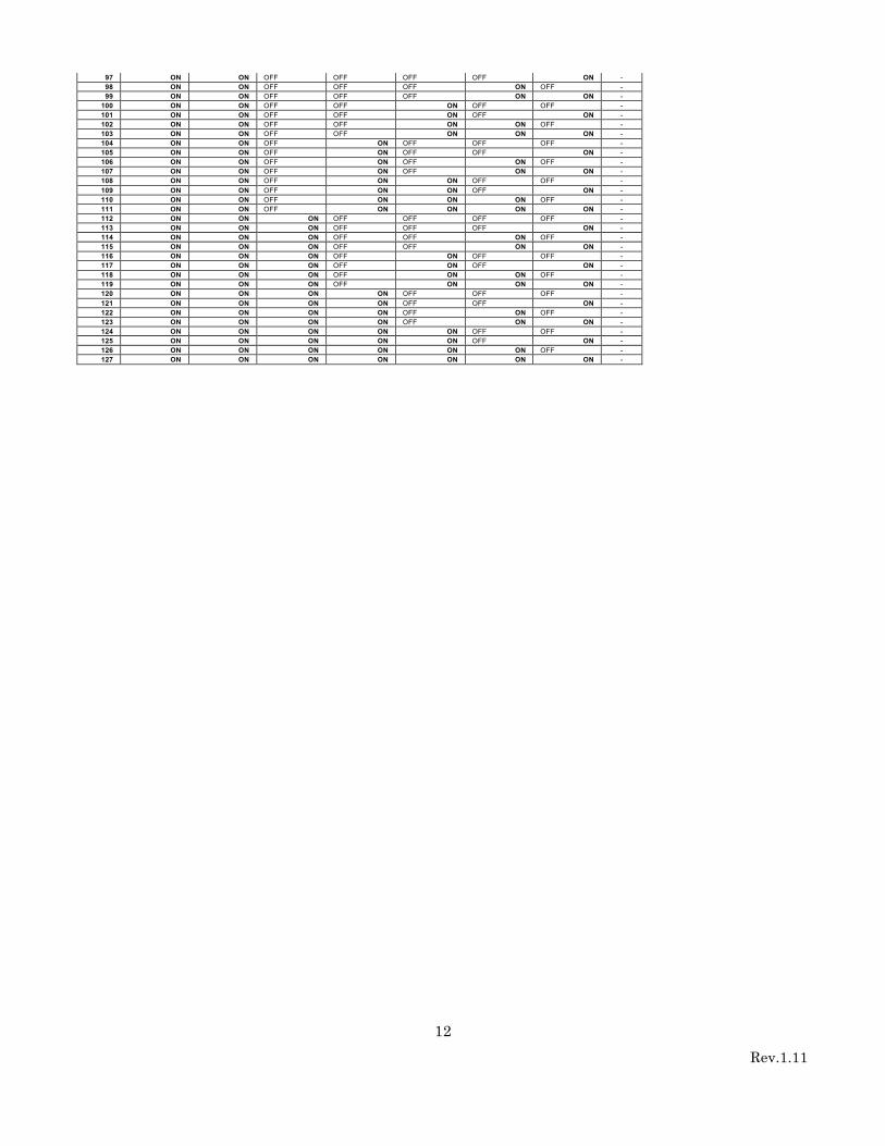
Switch 2 Group ID Setting Group ID AP GROUP bit6 AP GROUP bit5 AP GROUP bit4 AP GROUP bit3 AP GROUP bit2 AP GROUP bit1 AP GROUP bit0 Unused
1 OFF OFF OFF OFF OFF OFF ON - 2 OFF OFF OFF OFF OFF ON OFF - 3 OFF OFF OFF OFF OFF ON ON - 4 OFF OFF OFF OFF ON OFF OFF - 5 OFF OFF OFF OFF ON OFF ON - 6 OFF OFF OFF OFF ON ON OFF - 7 OFF OFF OFF OFF ON ON ON - 8 OFF OFF OFF ON OFF OFF OFF - 9 OFF OFF OFF ON OFF OFF ON -
10 OFF OFF OFF ON OFF ON OFF - 11 OFF OFF OFF ON OFF ON ON - 12 OFF OFF OFF ON ON OFF OFF - 13 OFF OFF OFF ON ON OFF ON - 14 OFF OFF OFF ON ON ON OFF - 15 OFF OFF OFF ON ON ON ON - 16 OFF OFF ON OFF OFF OFF OFF - 17 OFF OFF ON OFF OFF OFF ON - 18 OFF OFF ON OFF OFF ON OFF - 19 OFF OFF ON OFF OFF ON ON - 20 OFF OFF ON OFF ON OFF OFF - 21 OFF OFF ON OFF ON OFF ON - 22 OFF OFF ON OFF ON ON OFF - 23 OFF OFF ON OFF ON ON ON - 24 OFF OFF ON ON OFF OFF OFF - 25 OFF OFF ON ON OFF OFF ON - 26 OFF OFF ON ON OFF ON OFF - 27 OFF OFF ON ON OFF ON ON - 28 OFF OFF ON ON ON OFF OFF - 29 OFF OFF ON ON ON OFF ON - 30 OFF OFF ON ON ON ON OFF - 31 OFF OFF ON ON ON ON ON - 32 OFF ON OFF OFF OFF OFF OFF - 33 OFF ON OFF OFF OFF OFF ON - 34 OFF ON OFF OFF OFF ON OFF - 35 OFF ON OFF OFF OFF ON ON - 36 OFF ON OFF OFF ON OFF OFF - 37 OFF ON OFF OFF ON OFF ON - 38 OFF ON OFF OFF ON ON OFF - 39 OFF ON OFF OFF ON ON ON - 40 OFF ON OFF ON OFF OFF OFF - 41 OFF ON OFF ON OFF OFF ON - 42 OFF ON OFF ON OFF ON OFF - 43 OFF ON OFF ON OFF ON ON - 44 OFF ON OFF ON ON OFF OFF - 45 OFF ON OFF ON ON OFF ON - 46 OFF ON OFF ON ON ON OFF - 47 OFF ON OFF ON ON ON ON - 48 OFF ON ON OFF OFF OFF OFF - 49 OFF ON ON OFF OFF OFF ON - 50 OFF ON ON OFF OFF ON OFF - 51 OFF ON ON OFF OFF ON ON - 52 OFF ON ON OFF ON OFF OFF - 53 OFF ON ON OFF ON OFF ON - 54 OFF ON ON OFF ON ON OFF - 55 OFF ON ON OFF ON ON ON - 56 OFF ON ON ON OFF OFF OFF - 57 OFF ON ON ON OFF OFF ON - 58 OFF ON ON ON OFF ON OFF - 59 OFF ON ON ON OFF ON ON - 60 OFF ON ON ON ON OFF OFF - 61 OFF ON ON ON ON OFF ON - 62 OFF ON ON ON ON ON OFF - 63 OFF ON ON ON ON ON ON - 64 ON OFF OFF OFF OFF OFF OFF - 65 ON OFF OFF OFF OFF OFF ON - 66 ON OFF OFF OFF OFF ON OFF - 67 ON OFF OFF OFF OFF ON ON - 68 ON OFF OFF OFF ON OFF OFF - 69 ON OFF OFF OFF ON OFF ON - 70 ON OFF OFF OFF ON ON OFF - 71 ON OFF OFF OFF ON ON ON - 72 ON OFF OFF ON OFF OFF OFF - 73 ON OFF OFF ON OFF OFF ON - 74 ON OFF OFF ON OFF ON OFF - 75 ON OFF OFF ON OFF ON ON - 76 ON OFF OFF ON ON OFF OFF - 77 ON OFF OFF ON ON OFF ON - 78 ON OFF OFF ON ON ON OFF - 79 ON OFF OFF ON ON ON ON - 80 ON OFF ON OFF OFF OFF OFF - 81 ON OFF ON OFF OFF OFF ON - 82 ON OFF ON OFF OFF ON OFF - 83 ON OFF ON OFF OFF ON ON - 84 ON OFF ON OFF ON OFF OFF - 85 ON OFF ON OFF ON OFF ON - 86 ON OFF ON OFF ON ON OFF - 87 ON OFF ON OFF ON ON ON - 88 ON OFF ON ON OFF OFF OFF - 89 ON OFF ON ON OFF OFF ON - 90 ON OFF ON ON OFF ON OFF - 91 ON OFF ON ON OFF ON ON - 92 ON OFF ON ON ON OFF OFF - 93 ON OFF ON ON ON OFF ON - 94 ON OFF ON ON ON ON OFF - 95 ON OFF ON ON ON ON ON - 96 ON ON OFF OFF OFF OFF OFF -
12 Rev.1.11
97 ON ON OFF OFF OFF OFF ON - 98 ON ON OFF OFF OFF ON OFF - 99 ON ON OFF OFF OFF ON ON -
100 ON ON OFF OFF ON OFF OFF - 101 ON ON OFF OFF ON OFF ON - 102 ON ON OFF OFF ON ON OFF - 103 ON ON OFF OFF ON ON ON - 104 ON ON OFF ON OFF OFF OFF - 105 ON ON OFF ON OFF OFF ON - 106 ON ON OFF ON OFF ON OFF - 107 ON ON OFF ON OFF ON ON - 108 ON ON OFF ON ON OFF OFF - 109 ON ON OFF ON ON OFF ON - 110 ON ON OFF ON ON ON OFF - 111 ON ON OFF ON ON ON ON - 112 ON ON ON OFF OFF OFF OFF - 113 ON ON ON OFF OFF OFF ON - 114 ON ON ON OFF OFF ON OFF - 115 ON ON ON OFF OFF ON ON - 116 ON ON ON OFF ON OFF OFF - 117 ON ON ON OFF ON OFF ON - 118 ON ON ON OFF ON ON OFF - 119 ON ON ON OFF ON ON ON - 120 ON ON ON ON OFF OFF OFF - 121 ON ON ON ON OFF OFF ON - 122 ON ON ON ON OFF ON OFF - 123 ON ON ON ON OFF ON ON - 124 ON ON ON ON ON OFF OFF - 125 ON ON ON ON ON OFF ON - 126 ON ON ON ON ON ON OFF - 127 ON ON ON ON ON ON ON -

13 Rev.1.11
Connections
● LAN (PoE) connection
■ Wiring of Euroblock connector 1. A detachable Euroblock connector is provided for this unit’s connections. As shown in the figure below,
insert a slot-head screwdriver into the gap, and remove the Euroblock connector from this unit.

14 Rev.1.11
2. Connect wires to the Euroblock connector. Loosen the Euroblock connector screws with a slot-head
screwdriver, peel off the insulating material of each wire, and twist the conductor wires firmly, insert the
ends of the conductor wires into the Euroblock connector, and tighten the Euroblock connector screws.
(Fix wires using the supplied tying band.)
Note:
• Stranded wire is highly recommended.
• Wire insulation must be removed.
• Do not use solder to tin the wire.
• The recommended maximum wires length is 15 m {49 feet}.
● Connection of E2 CNT terminals An external device is connected between E2 CNT and COM. These terminals are isolated from the internal circuit by a photo coupler.
● Connection of ALERT BUTTON terminals An external device is connected between ALERT BUTTON and GND. These terminals operate by closing their circuits. The GND
terminal is connected to GND in this unit. A set of “dry relay” contacts are recommended to activate these features.
Input format: transistor input
Electrical specifications: Open voltage 5 VDC, short-circuit current 2 mA
E2 CNT
ALERT BUTTON
E2 Com E2 Cont
Alert Button GND

15 Rev.1.11
Precautions for Installation The installation should be carried out following local standards for electrical products. Warning ● Be sure to contact your dealer for installation. Before installing, turn off the power of the connecting product. In addition, be sure to read these "Precautions" and the safety precautions carefully and follow the instructions. Moreover, be sure to read operating instructions of the connecting product as well. ● Static Electricity Discharge any static electricity charged in your body by touching a metallic area before installing in order to prevent damage caused by static electricity. ● Install the WAP within a range that the receiver can reach ● Avoid installing near a warm airflow path. In addition, if the product is installed in locations with a lot of moisture, dust or vibration, there is a risk of damage. ● Do not install and use in following locations: 1) Locations directly affected by rain or water (including spaces under the eaves). 2) Locations such as pools where medical agents are used. 3) Locations such as kitchens or factory workshops where there is a lot of vapor or oil, and special environments such as in flammable atmospheres. 4) Locations where radiation or X-rays and strong electric fields or magnetism arise. 5) At sea or along the coast, and locations such as hot springs where corrosive gases arise. 6) Locations with a lot of vibrations caused by vehicle or ships (this is not a product for vehicles). 7) Locations where water drops made by condensation will splash. ● If there are any devices causing interference, product may be impossible to use. In that case, install the product farther away until it can be used. ● For tightening bolts and screws, pay attention to the following points: 1) Torque control is necessary for tightening the bolts and screws. 2) Torque wrench and torque driver are necessary for controlling the torque. 3) Never use any impact driver or electric drill because torque control is difficult even if they have a clutch. Their use may result in damage to the mounting part. ● After mounting, confirm visually that the product is firmly and stably fixed. If the product is properly installed, it will not wobble or make noise. ● In installing this WAP, be aware of the following: 1) Be sure that the installation is carried out by qualified personnel when installing at high locations. 2) Before installation, confirm that there is nobody around. 3) In order to carry out the installation safely and surely, pay close attention to the safety control. ● Do not apply strong impact on this unit. Failure to observe this may damage this unit.

16 Rev.1.11
Installation
Warning
• Before installing, be sure to turn off the power of the WAP.
There is a risk of electric shock.
■ Installation of the WAP ● When using a ceiling panel When installing the WAP and cables in a removable ceiling, follow the instructions shown below.
1) Make a hole in the ceiling panel
Remove the ceiling panel, drill a hole of approx. φ35 mm {φ1-1/3 inches} through the panel, and run the cables to be connected
through the hole.
2) Insert the ceiling panel between the mounting bracket and the plate, and fix it with screws and nuts.
Note:
• Fix this unit firmly with specified torque with a tool such as a torque driver.
3) Connect the necessary cables to the WAP
Connect the cables in reference to Connections (on Page 13).
4) Install the WAP
Hook a WAP on the hooks of the mounting bracket. (Four places)
Open the screw cover.
Install a WAP to the included mounting bracket using a screwdriver and provided screw.
Close the screw cover.
Note:
• Fix this unit firmly with specified torque with a tool such as a torque driver.
5) After the installation, check that all parts are firmly installed.
Check visually for loose parts and connections.

17 Rev.1.11
Step 1
Step 2

18 Rev.1.11
IMPORTANT:
• Procure 4 screws (M4) to secure the mounting bracket (accessory) to a ceiling or a wall according to the material of the installation
area. In this case, wood screws and nails should not be used. For mounting a receiver on a concrete wall, use an anchor bolt (M4) or
an AY plug bolt (M4) for securing. (Recommended tightening torque: 1.6 N・m {1.18 lbf・ft})
• Mount the mounting bracket (accessory) in accordance with the instructions
• Required pull-out capacity of a single screw/bolt is 196 N {44 lbf} or more.
• If a ceiling board such as plaster board is too weak to support the total weight, the area shall be sufficiently reinforced.
• Install the mounting bracket (locally procured) in the foundation area of the architecture or where sufficient strength is assured.
• To preserve the mounting strength, do not use wooden screws to secure the mounting bracket (locally procured).
Installation place. Applicable mounting bracket. Recommended screw. Number of screws.
Minimum pull-out strength (per 1 pc.). Wall Mounting bracket (Accessory) M4 4 pcs.
When mounting a wall When installing the WAP and cables in a removable wall, follow the instructions shown below.
1) Install the mounting bracket to a wall using a screwdriver and provided screw
Note:
• Fix this unit firmly with specified torque with a tool such as a torque driver
2) Connect the necessary cables to the WAP
Connect the cables in accordance with the directions in the Connections section on page 13.
3) Install the WAP.
Hook a WAP on the hooks of the mounting bracket. (Four places)
Open the screw cover.
Fix a WAP to the mounting bracket with a screwdriver and provided screw.
Close the screw cover.
Note:
• Fix this unit firmly with specified torque with a tool such as torque driver.
4) After installation, check that all parts are firmly installed.
Check visually for loose parts and connections.

19 Rev.1.11
Mounting bracket
Step 1
Screw cover
Screwdriver
Step 2
Step 3

20 Rev.1.11
CGI command list
The following CGI commands are used in a XD MIC SYSTEM.
No Function block Name Explanation Requestor CGI command
name
Serial command AP
->PC PC
->AP
1 Settings ID registration start Instruction
It changes into ID registration receptionist state by the instructions from PC for administrators. ○ /cgi-bin/regist_start
-
2 Settings ID registration end
instruction
ID registration receptionist state is terminated by the request from PC for administrators. ○
/cgi-bin/regist_end
-
3 Notify PC for administrators of completion of ID registration of a receiver. ○
-
4 Accompanying ID registration information notification
The DECT ID of the portable part registered newly is notified to PC for administrators. ○ /cgi-bin/id_reg_send
CMI
5 Settings Delete Receiver registration instruction
Receiver ID registered into the access point is deleted. ○ /cgi-bin/rcv_delete
6 Settings Delete Microphone registration instruction
The microphone registered into the receiver is deleted. ○ /cgi-bin/mic_delete
7 Accompanying Microphone location notification
Location of a microphone (The receiver and access point which the microphone has established a wireless connection) is sent to PC for administrators. This notification is sent when a microphone has wireless connection with receiver.
○ /cgi-bin/location_send
CCS
8 Accompanying Microphone release notification
It is notified to PC for administrators that connection of microphone was canceled. ○ /cgi-bin/mic_release_
send
CCS
9 Application control notice of a result The notice of a result to receivers ○ /cgi-bin/instruction_re
sult -
10 Alert Alert start notification An alert is started by an operation of a microphone or an operation of the alert notification button connected to the receiver.
○ /cgi-bin/alert_start
ALM ALB ALL
11 Alert Alert end instruction An alert is canceled by the request from PC for administrators. ○ /cgi-bin/alert_end RAL
12 Alert Alert monitor start instruction Alert monitoring start ○ /cgi-bin/monitor_start
-
13 Alert Monitor end instruction Voice monitoring from a microphone is ended by instructions of PC for administrators during an alert.
○ /cgi-bin/monitor_end
-
14 Alert Monitor end notification
It will notify the end of the alert monitor from the access point. ○ /cgi-bin/monitor_end
15 Sound Control Send sound user management
Get user ID, in order to send sound to PC for administrators from an access point. ○ /cgi-bin/getuid
-
16 Sound Control Send sound control The sending sound to PC for administrators from an access point is started / stopped. ○ /cgi-bin/dmic_audio_
send
-
17 Sound Control Keep alive (WAP) Continuation of sound transmission (WAP) ○ /cgi-bin/keep_alive -
18 Sound Control Check Sound session Release of UID for sound distribution ○ /cgi-bin/man_session -

21 Rev.1.11
19 Status Get Access point state Get Access point state ○ /cgi-bin/get_apstatus QPW
20 Status Get Microphone state Get present state of a microphone ○ /cgi-bin/get_micstatus
-
21 Status Send Microphone state The notice of the state of a microphone ○ /cgi-bin/send_micstatus
22 Status Access point start notification
The start of an access point is notified to PC for administrators. ○ /cgi-bin/ap_start -
23 Status Get product information Get ( product number / MAC address / software version ) ○ /cgi-bin/getinfo
-
24 Status Send receiver product information Send receiver product information ○ /cgi-bin/send_rcv_inf
o
-
25 Status Get abnormal history Get abnormality history of the access point or receiver. (from AP ) ○ /cgi-bin/data_downlo
ad
-
26 Status Upload A file is uploaded from WAP to PC for administrators. ○ /cgi-bin/upload
-
27 Status Unusual notice of access point
The abnormalities of an access point are notified to PC for administrators. ○ /cgi-bin/error
-
28 Settings Set NTP Server Set time sever ○ /cgi-bin/time -
29 Settings User Authentication Setting
A password is set to a user name for authentication ○ /cgi-bin/reg_user
-
30 Settings Authentication user delete Authentication user delete ○ /cgi-bin/del_user
31 Settings Network Setting Network Setting ○ /cgi-bin/network -
32 Settings Reboot Reboot the apparatus. ○ /cgi-bin/initial -
33 Settings Get setting value Get setting value ○ /cgi-bin/getdata -
34 Settings The present time inquiry The present time inquiry to PC for administrators ○ /cgi-bin/get_time
-
35 Settings VPS setting Registration of the PC used as VPS ○ /cgi-bin/vps_setting
36 Status Get DIP switch value Get DIP switch value(Access point / Receiver ) ○ /cgi-bin/get_sw -
37 Status Send receiver DIP switch value Send receiver DIP switch value ○ /cgi-bin/send_rcv_sw -
38 Accompanying E1 Notification Notification that E1 has been run from the microphone ○ /cgi-bin/ce1 CE1
39 Accompanying Rec monitor start Rec monitor start(Instructions from PC for VPS) ○ /cgi-bin/rec_monitor_start
40 Accompanying
Rec monitor end Rec monitor end ○ /cgi-bin/rec_monitor_end
41 Rec monitor end notification Rec monitor end notification from WAP ○ /cgi-bin/rec_monitor_
end
42 Accompanying E2 Notification E2 contact state change notification ○ /cgi-bin/ce2 CE2 43 Accompanying E2 Ack E2 Ack ○ /cgi-bin/e2ack 44 Accompanying Get E2 state Get the E2 state of receiver ○ /cgi-bin/get_qe2 QE2 45 Accompanying Send E2 state Send the E2 state of receiver ○ /cgi-bin/send_qe2
46 Control Software MUTE (Altogether MUTE) MUTE ON/OFF(CH1,CH2,MIX OUT) ○ /cgi-bin/sam
47 Control LED lighting set LED1 / LED2 / LED3 forced lighting settings ○ /cgi-bin/sld SLD

22 Rev.1.11
48 Control LED lighting restoration All at once the end of the LED display that was forced lighting by the LED light setting ○ /cgi-bin/rld RLD
49 Control Set the microphone transmission area Set the area to mute the sound. ○ /cgi-bin/saa SAA
50 Control Inquire the microphone
transmission area setting.
Inquire microphone's transmission area (from receiver)
○ /cgi-bin/saa_inq
51 Control Send microphone
transmission area setting.
Notification microphone's transmission area(from receiver)
○ /cgi-bin/saa_send
52 Control Set Auto Power Control The radio strength between the access point and the receiver is controlled automatically.
○ /cgi-bin/auto_power
53 Control Send setting result of auto power control
Send setting result of auto power control ○ /cgi-bin/auto_power_result
54
Control Get RF signal strength
" <Access point> Get RF signal strength an access point receives from receiver <Receiver> Get RF signal strength receiver receives from access point
○
/cgi-bin/radio_power_inq
55 Control Send RF signal strength
Send RF signal strength receiver receives from access point
○ /cgi-bin/radio_power_send
56 Control Set Paired Alert Area Set the area for changing status from the Paired Alert to the Non-paired Alert
○ /cgi-bin/san SAN
57 Control Get Paired Alert Area Inquire microphone's transmission area(from receiver)
○ /cgi-bin/san_inq
58
Control Send Paired Alert Area Notify the microphone's transmission area(from
receiver)t
○
/cgi-bin/san_send
59 Control Reset Reset (E2,E1make,Volume value) ○ /cgi-bin/srs
Glossary:
WAP: Wireless Access Point - this unit (K-SAP14)
Alert: Alert information that sends when pressing the E2 buttons on the K-STD14 microphone
Alert Notification Button: Alarm push-button (optional accessory)
Alert only WAP: WAP that accepts only microphone alerts. (not connected to the RCV)
(DIP-switch1-1=ON)
Linkup: Connection establishment state
RF power: Radio Frequency power
Authentication Password: Authentication password when connecting to the WAP
Group ID: Only WAP and RCV with the same group ID will be able to communicate
ID registration: Connection registration of WAP and RCV
E1: Signal that sends when the REC button is pressed Audio mute area: in reference to "Command List [SAA] " Paired Alert: Alerts from the registered microphone that are connected
Non-pair Alert: Alerts from unregistered microphones
HEMS: Head End Management Software
VPS: View Pass Server

23 Rev.1.11
Specifications
General Power
PoE (IEEE 802.3af ) Class
Class 1 Operating temperature range 0°C - 40°C {32°F - 104°F} Dimensions
7.28" (W) x 6.3" (H) x 1.26" (D) (185 mm (W) x 160 mm (H) x 32 mm (D))
(excluding projections) Mass Finish ABS resin white color
RF communication Radio Standard XD Frequency Range 1,920.0~1,930.0 MHz Coverage 20 m (NORMAL) / 30 m (Hi POWER)
Control terminal E2 CNT, COM Output format: open collector, make output
Electrical specifications: control voltage; 30 V, control current; 20 mA Alert button Input format: transistor input
Electrical specifications: open voltage; 5 VDC, short-circuit current; 2 mA
LAN Interface Connectors RJ-45 (Type for LAN)
Recommended cable LAN (Cat5e or more)
Network protocol IPv4
100 BASE-TX, 10 BASE-T (Auto/Full/Half)
Accessories Mounting bracket: 1 Tie for cable: 2 Screw: 1 Leaflet: 2 (Safety precautions, open software license) Unattached: Operating Instructions: None. Total operating instructions are prepared by Audio Enhancement. Warranty Card: None, the warranty period is described in the contract.