14.07.04 fsggc dom aft1 - citizen valves · 2 11 introduction ail forged steel gate, globe and...
TRANSCRIPT

12 1
API 602 • BS 5352
BS 6364
ASME B16.34 • MSS SP 84
PB No. : C1110-0/12.04 (supersedes C1096-0/06.00)As we continuously endeavour to improve our products, the data given herein are subject to change without notice.
AUDCO INDIA LIMITEDAdministrative Of fice
Mount-Poonamallee Road, Manapakkam, Post Bag 976, Chennai 600 089, INDIA.Tel : (044) 22492323. Fax : (044) 22495055, 22494055.Website : www.ailvalves.com
Manufacturing Plants
Mount-Poonamallee Road, Manapakkam, Chennai 600 089, INDIA.Enathur, Kancheepuram 631 552, INDIA.B8, MMDA Industrial Area, Maraimalai Nagar 603 209, INDIA.
Marketed by
LARSEN & TOUBRO LIMITEDValves Business Unit
Post Bag 5247, Chennai 600 002, INDIA. Tel : (044) 28462015-19. Fax : (044) 28462102/03.P.O. Box 619, Kolkata 700 071, INDIA. Tel : (033) 22822435/22823301. Fax : (033) 22828406.P.O. Box 8901, Mumbai 400 072, INDIA. Tel : (022) 28581118/28581432. Fax : (022) 28581027.P.O. Box 6223, New Delhi 110 015, INDIA. Tel : (011) 51419579-83. Fax : (011) 51419596.
AUDCO INDIA LIMITED
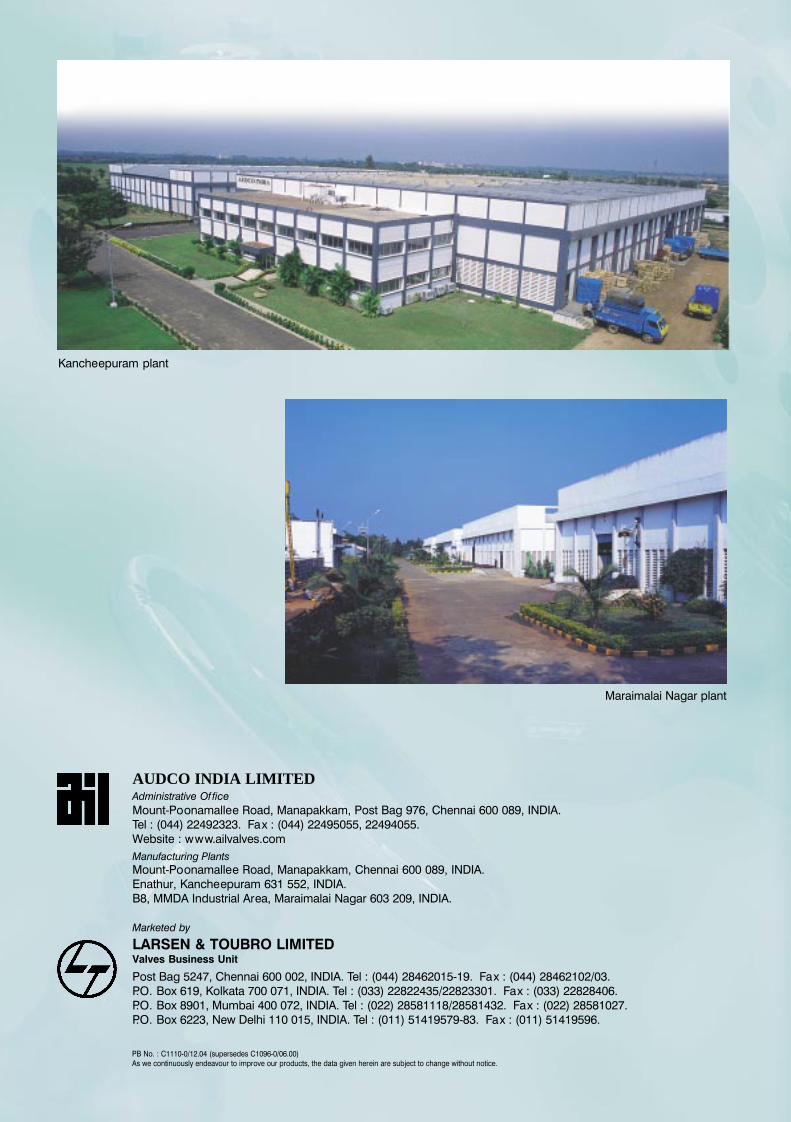
Kancheepuram plant
Maraimalai Nagar plant
AIL FORGED STEEL
GATE, GLOBE & CHECK
VALVES
ASME Class 150 - 2500
8mm - 50mm (1/4” - 2”)

2 11
Introductio
n AIL Forged Steel Gate, Globe and Check Valves have established themselves the world over for their quality, reliability and
long service. Rugged and compact in design, these valves are manufactured to the latest international designs using advanced
manufacturing techniques and stringent quality control checks. The valves are regularly supplied to major Indian and international
clients including oil refining companies and EPC contractors. They are available in a range of sizes starting from 1/4” to 2” (inreduced-bore design) and from 3/8” to 11/2” (in full-bore design).
AUDCO INDIA LIMITED (AIL) is a leading valve manufacturer, with a strong presence in India and overseas. AIL has three
manufacturing facilities located in Southern India. The main plant is located in Manapakkam, Chennai. The two other plants
are at Maraimalai Nagar, 40 kilometres south and at Kancheepuram, 70 kilometres west of the main plant. The plants are
equipped with modern manufacturing facilities with special-purpose machines, automatic welding equipment, heat treatmentfurnaces and testing equipment for total control of all manufacturing operations. In-house metallurgical and NDE laboratories,
and calibration facilities with modern equipment provide support to ensure the quality of products manufactured. AIL
manufactures a wide variety of industrial valves. The Quality Management System in all three plants is certified to ISO 9001:2000
System.
02
Chennai plant
QQuality Policy
Audco India Limited is committed to
Total Customer Satisfaction
We achieve this by
• Maintaining a high standard of
quality consistent with the customer
requirements
• Complying with the Codes,
S t a n d a r d s , C u s t o m e r
Specifications, Statutor y and
Regulator y requirements as
applicable to our Products
• Continually improving the
ef fectiveness of Qualit y
Management System to add value
to our Products
AIL
Y-p
attern V
alv
es
11
ValveClass 1500 Class 2500
Size A B C D E F App.Wt. A B C D E F App.Wt.(kg) (kg)
15 97.5 22021.72
9.7 128 1/2”-14NPT 6 115 24521.72
9.7 135 1/2”-14NPT 722.23 22.23
20 115 24527.05
12.7 135 3/4”-14NPT 7 115 24527.05
12.7 135 3/4”-14NPT 727.56 27.56
25 138 29533.78
12.7 165 1”-11.1/2NPT 10 138 29533.78
12.7 165 1”-11.1/2NPT 1034.29 34.29
40 185 39248.64
12.7 238 11/2”-11.1/2NPT 19 202 41548.64
12.7 255 11/2”-11.1/2NPT 2549.15 49.15
50 185 39261.11
16.0 238 2”-11.1/2NPT 19 202 41561.11
16.0 255 2”-11.1/2NPT 2561.62 61.62
Dimensional details (in mm, unless specified)
ValveClass 1500 Class 2500
Size A B C D E App.Wt. A B C D E App.Wt.(kg) (kg)
15 97.5 7121.72
9.7 1/2”-14NPT 2 115 8521.72
9.7 1/2”-14NPT 2.522.23 22.23
20 115 8527.05
12.7 3/4”-14NPT 2.5 115 8527.05
12.7 3/4”-14NPT 2.527.56 27.56
25 138 9533.78
12.7 1”-11.1/2NPT 5 138 9533.78
12.7 1”-11.1/2NPT 534.29 34.29
40 185 12048.64
12.7 11/2”-11.1/2NPT 9 202 13548.64
12.7 11/2”-11.1/2NPT 949.15 49.15
50 185 12061.11
16.0 2”-11.1/2NPT 9 202 13561.11
16.0 2”-11.1/2NPT 961.62 61.62
Dimensional details (in mm, unless specified)
Note : 40mm valves can be of fered with butt-weld and socket-weld ends to suit 32mm pipe. 50mm valves can be of fered with butt-weld ends to suit 65mm pipe. Class 900 valves available on request.
AIL Manufacturing ProgrammeD
ES
IG
N
ST
AN
DA
RD
AP
I 602
/ B
S 5
352
BS
5352
AS
ME
B16
.34/
MS
S S
P 8
4Valve End ASME
1/4” 3/8” 1/2” 3/4” 1” 11/4”11/2” 2”Type Conn. Class
screwed/800
RB � � � � � � � �
sock.wld FB � � � � � �
sock.wld 1500 SP � � � � � � �
150RB � � � � � �
FB � � � � �
flanged 300RB � � � � � �
FB � � � � �
600RB � � � � � �
FB � � � � �
screwed/800
RB � � � � � � � �
sock.wld FB � � � � � �
150RB � � � � � �
FB � � � � �
flanged 300RB � � � � � �
FB � � � � �
600RB � � � � � �
FB � � � � �
800RB � � � � � �
screwed/ FB � � � � �
sock.wld800
RB � � � � � �
FB � � � � �
screwed/800
RB � � � � � �
sock.wld FB � � � � �
150RB � � � � � �
flanged FB � � � � �
300RB � � � � � �
FB � � � � �
600RB � � � � � �
FB � � � � �
screwed/1500 FB � � � � � �
sock.wld/2500 FB � � � � � �
but t.wld1500 FB � � � � � �
2500 FB � � � � � �
CryogenicGate & Globe
Valves
Globe & CheckValves
Y-patternGlobe Valves
BS
636
4
Y-patternCheck Valves
Sl. No. Part Description Specification
1 Body & BonnetCarbon Steel Alloy Steel
2 Cap
3 Disc Type 410 SS, in-situ stellited seat
4 Spring Nimonic 90 / Inconel X 750
5 Gasket Graphite
Material Specification
ASTM A105 orIS 1875 Cl. 2
ASTM A182Gr. F22
ASTM A182 Gr.F22,in-situ stellited seat
ASTM A105,in-situ stellited seat
End dimensions of 50mm valves can be machined to suit 65mm pipe. For details, refer to AIL.Class 900 valves available on request. For dimensions, refer to AIL.
Gate Valves
Bellows-SealedGate Valves
RB - Reduced Bore - bore conforms to BS 5352 Reduced Bore and API 602 Standard Port
FB - Full Bore - bore conforms to BS 5352 Standard Bore
SP - Standard Port - bore conforms to API 602 Standard Port
Bellows-SealedGlobe Valves
AP
I602
BS
5352
Y-pattern Globe Valves
Sl. No. Part Description Specification
1 & 2 Body & BonnetCarbon Steel Alloy Steel
3 Yoke Bush ASTM A439 Type D2
4 Disc Type 410 SS, in-situ stellited seat
5 Stem Type 410 SS
6 Stem packing Graphite with braided end rings
7 Handwheel SG Iron
8 Gland Type 410 SS
9 Gland Flange BS 970 : 709M40 COND R
10 Handwheel Nut Steel
11 Gland Stud ASTM A193 Gr. B7
12 Gland Stud Nut ASTM A194 Gr. 2H
13 Gasket Graphite
Material Specification
ASTM A182 Gr.F22,in-situ stellited seat
ASTM A105,in-situ stellited seat
Y-pattern Check Valves
10 3
Technic
al
Inform
atio
n
03
AIL
Y-p
attern V
alv
es
10
AIL Forged Steel Y-pat tern Globe and Check
Valves have established themselves in the industry
for their rugged and compact design, and reliable
service. These valves are of fered in Carbon Steel andAlloy Steel. They are available in a range of sizes
starting from 1/4” to 2” (in reduced-bore design) and
from 3/8” to 11/2” (in full-bore design).
The rugged construction ensures an ideal body and
bonnet, suited to handle high pressure andtemperatures - up to 4250C in carbon steel and 5400C
in alloy steel.
The Y-pattern design ensures a near-per fect straight
flow which significantly reduces pressure drop and
turbulence when compared to conventional designs.
As a standard, valves are supplied with screwed body-
bonnet joint, which ensures ease of inspection and
in-line maintenance, thus minimising downtime.
AIL Y-pattern valves can be of fered to NACE MR-0175 andother special NACE requirements. They can also be
supplied with IBR certification.
Familiarity with our catalogue numbering is not necessary when specifying or ordering our valves. A fulldescription of the valve provided by you is translated into a catalogue number as per the system shown.
For any other special requirement, add SPL to the catalogue number and provide details.
Y-pattern Globe/Check Valves
Y-pattern Globe ValvesDisc and SeatThe disc is provided with two integral rings to guide it throughoutits travel in the body. This minimises side thrust on the disc andeliminates bending of the stem even at high flow velocities. Bodyand disc seats are hard-faced to ensure a long, trouble-free lifecycle.
Disc-Stem ConnectionThe unique joint at the discand the stem provides for aflexible yet strong connectionthat enables the disc to freelyfloat on the stem. This resultsin perfect alignment of the discwith the stem.
Body-Bonnet JointThe bonnet is screwed to the body with ACME threads to ensureease of dismantling and resistance to galling. A graphite gasketis provided for tight sealing. This joint is tack-welded to preventloosening while in service. The bonnet can be easily removedfor inspection and maintenance of inner parts. The joint canalso be seal-welded on request.
PackingDie-moulded graphite rings are used as packing to provide foroptimal per formance at high pressures and temperatures. Twofilament rings provided at the top and bot tom of the graphitepacking rings act as anti-extrusion rings. Moreover, a smoothsurface finish on the stuf fing box along with a precision-machinedstem ensure optimum sealing and packing life.
StemThe stem is ACME-threaded and is ground for smooth operation.
Gland ArrangementThe two-piece ball-type gland flange arrangementensures uniform loading on the packing even incase the gland is unevenly tightened.
InstallationGlobe valves can be installed, either with the flowover or under the disc, depending on the servicecondition. However, in the case of steam and othersuch hot services that include drain lines, globevalves ought to be installed with flow over the discto aver t unseating caused as an ef fect ofdif ferential thermal expansion that would otherwiseresult in leakage and consequent wire drawing.
End ConnectionSocket-weld ends to ASME B16.11But t-weld ends to BS 5352 Annexure DScrewed ends (NPT) to ASME B1.20.1
Bore DiameterBoth Class 1500 and Class 2500 valves have borediameters conforming to Class 1500-StandardBore of BS 5352, with the exception of 15mm Class2500 valve which has a bore diameter of 14.5mm.
Y-pattern Check ValvesY-pat tern Check Valves incorporate the samedesign and construction features as their globevalve counterpar ts. The spring-loaded discminimises chat tering and enables the valve to beinstalled either in a horizontal or vertical position.
Size Valve type Pressure Class End Connection Trim Body material
15 - 15mm
20 - 20mm
25 - 25mm
40 - 40mm
50 - 50mm
6 - Scr. Bonnet7 - Seal-welded
Bonnet
GLOBE 15- Class 150025- Class 2500
3 - Butt-weld4 - Screwed NPT5 - Socket-weld
U - Hardfacedseatingsur face
NIL - A105F11F22
8 - Scr. Cap9 - Seal-welded
Cap
F316F316LF347
NIL - StandardIBR - IBR-cer tified
Options
CHECK
Ordering Information - Y-pat tern Valves
Compliance Standards
BS 6364API 598 BS 5352
Valve Type Valve DesignFace-to-face
End ConnectionPressure / Temp. Valve inspection
dimension rating** and testing
Gate ValvesAPI 602 API 598
ASME B16.34 BS 5352
Globe and BS 5352 API 598Check Valves
BS 5352*ASME B16.34 BS 5352
Cryo Gate &BS 6364
Globe ValvesBS 6364
Y-Globe and ASME B16.34ASME 16.34 API 598
Check Valves MSS SP 84
AIL Standard(screwed/socket-weld/
butt-weld)
ASME B16.10BS 2080(flanged)
ASME B1.20.1 (NPT) • BS 21 / ISO 7(screwed - taper)
ASME B16.5 RF 125-250 Ra(flanged)
AIL Standard
ASME B16.11(socket-weld)
BS 2779 / ISO 228 • BS 21 / ISO 7(screwed - parallel)
API 602*BS 5352
For Class 150 valves, the flange drilling dimensions will be as per Class 150 and all other dimensions as per Class 300.End flanges are welded onto the body.Bellows-Sealed Gate and Globe valves conform to BS 5352.Socket-weld Class 800 Reduced Bore valves conform to Class 3000 (or Sch.80/Sch.XS) fit tings of ASME B16.11.Socket-weld Class 800 Full Bore valves conform to Class 6000 (or Sch.160) fit tings of ASME B16.11.Socket-weld Class 1500 Standard Port valves conform to Class 9000 (or Sch.XXS) fit tings of ASME B16.11.*Full Bore design also conforms to ASME B16.34 ** API 602/BS 5352 for Class 800 and ASME B16.34 for Class 150/300/600/1500/2500.
see page 10
ValveType
ASMEClass
H Y D R O S T A T I C A I R
Shell Back SeatSeat Closure
High Pressure Low PressureSeat
psi kg/cm2 psi kg/cm2 psi kg/cm2 psi kg/cm2 psi kg/cm2
150 450 32 315 22 - - - - 90 6.3300 1125 79 815 57 - - - - 90 6.3600 2225 156 1630 115 - - - - 90 6.3800 3000 211 2200 155 - - - - 90 6.31500 5575 392 4080 287 - - - - 90 6.3150 450 32 315 22 315 22 - - 90 6.3300 1125 79 815 57 815 57 - - 90 6.3600 2225 156 1630 115 1630 115 - - 90 6.3800 3000 211 2200 155 2200 155 - - 90 6.3150 450 32 - - 315 22 80 6 - -300 1125 79 - - 815 57 210 15 - -600 2225 156 - - 1630 115 410 29 - -800 3000 211 - - 2200 155 550 39 - -
800 3000 211 2200 155 - - - - 90 6.3
800 3000 211 2200 155 2200 155 - - 90 6.3
Gate
Globe
Check
B’SealedGate
B’SealedGlobe
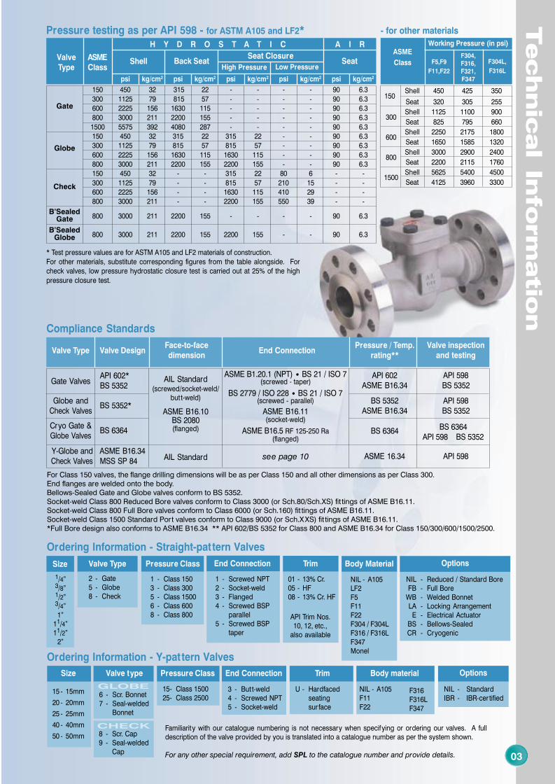
Pressure testing as per API 598 - for ASTM A105 and LF2*
* Test pressure values are for ASTM A105 and LF2 materials of construction.For other materials, substitute corresponding figures from the table alongside. Forcheck valves, low pressure hydrostatic closure test is carried out at 25% of the highpressure closure test.
Working Pressure (in psi)
150Shell 450 425 350
Seat 320 305 255
300Shell 1125 1100 900
Seat 825 795 660
600Shell 2250 2175 1800
Seat 1650 1585 1320
800Shell 3000 2900 2400
Seat 2200 2115 1760
1500Shell 5625 5400 4500
Seat 4125 3960 3300
ASME
Class F5,F9
F11,F22
F304,F316,F321,F347
F304L,
F316L
- for other materials
Ordering Information - Straight-pat tern Valves
Trim
NIL - A105LF2F5F11F22F304 / F304LF316 / F316LF347Monel
Body Material
NIL - Reduced / Standard BoreFB - Full Bore
WB - Welded BonnetLA - Locking ArrangementE - Electrical Actuator
BS - Bellows-SealedCR - Cryogenic
Options
1 - Screwed NPT2 - Socket-weld3 - Flanged4 - Screwed BSP
parallel5 - Screwed BSP
taper
End Connection
1 - Class 1503 - Class 3005 - Class 15006 - Class 6008 - Class 800
Pressure Class
2 - Gate5 - Globe8 - Check
Valve Type
1/4”3/8”1/2”3/4”1”
11/4”11/2”
2”
Size
01 - 13% Cr.05 - HF08 - 13% Cr. HF
API Trim Nos.10, 12, etc.,
also available
4 9
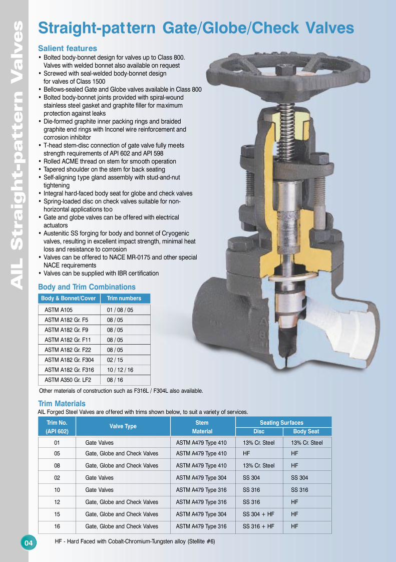
Salient features• Bolted body-bonnet design for valves up to Class 800.
Valves with welded bonnet also available on request• Screwed with seal-welded body-bonnet design
for valves of Class 1500• Bellows-sealed Gate and Globe valves available in Class 800• Bolted body-bonnet joints provided with spiral-wound
stainless steel gasket and graphite filler for maximumprotection against leaks
• Die-formed graphite inner packing rings and braidedgraphite end rings with Inconel wire reinforcement andcorrosion inhibitor
• T-head stem-disc connection of gate valve fully meetsstrength requirements of API 602 and API 598
• Rolled ACME thread on stem for smooth operation• Tapered shoulder on the stem for back seating• Self-aligning type gland assembly with stud-and-nut
tightening• Integral hard-faced body seat for globe and check valves• Spring-loaded disc on check valves suitable for non-
horizontal applications too• Gate and globe valves can be of fered with electrical
actuators• Austenitic SS forging for body and bonnet of Cryogenic
valves, resulting in excellent impact strength, minimal heatloss and resistance to corrosion
• Valves can be of fered to NACE MR-0175 and other specialNACE requirements
• Valves can be supplied with IBR certification
AIL
S
traig
ht-p
attern V
alv
es
04
AIL
S
traig
ht-p
attern V
alv
es
09
Other materials of construction such as F316L / F304L also available.
Body & Bonnet/Cover Trim numbers
ASTM A105 01 / 08 / 05
ASTM A182 Gr. F5 08 / 05
ASTM A182 Gr. F9 08 / 05
ASTM A182 Gr. F11 08 / 05
ASTM A182 Gr. F22 08 / 05
ASTM A182 Gr. F304 02 / 15
ASTM A182 Gr. F316 10 / 12 / 16
ASTM A350 Gr. LF2 08 / 16
Body and Trim Combinations
Trim Materials
Trim No.Valve Type
Stem Seating Surfaces
(API 602) Material Disc Body Seat
01 Gate Valves ASTM A479 Type 410 13% Cr. Steel 13% Cr. Steel
05 Gate, Globe and Check Valves ASTM A479 Type 410 HF HF
08 Gate, Globe and Check Valves ASTM A479 Type 410 13% Cr. Steel HF
02 Gate Valves ASTM A479 Type 304 SS 304 SS 304
10 Gate Valves ASTM A479 Type 316 SS 316 SS 316
12 Gate, Globe and Check Valves ASTM A479 Type 316 SS 316 HF
15 Gate, Globe and Check Valves ASTM A479 Type 304 SS 304 + HF HF
16 Gate, Globe and Check Valves ASTM A479 Type 316 SS 316 + HF HF
HF - Hard Faced with Cobalt-Chromium-Tungsten alloy (Stellite #6)
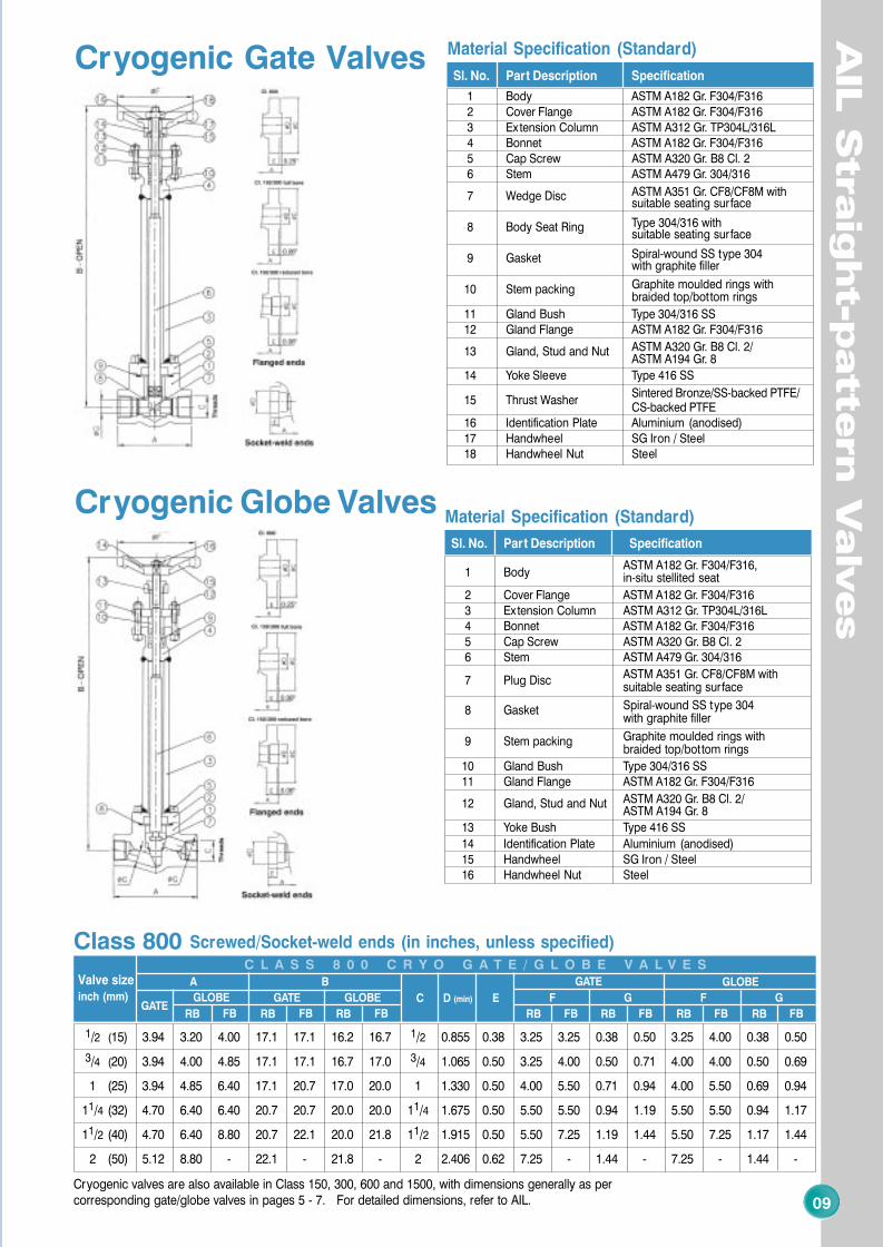
Cryogenic Gate Valves
Cryogenic Globe Valves
Sl. No. Part Description Specification
1 Body ASTM A182 Gr. F304/F3162 Cover Flange ASTM A182 Gr. F304/F3163 Extension Column ASTM A312 Gr. TP304L/316L4 Bonnet ASTM A182 Gr. F304/F3165 Cap Screw ASTM A320 Gr. B8 Cl. 26 Stem ASTM A479 Gr. 304/316
7 Wedge Disc ASTM A351 Gr. CF8/CF8M withsuitable seating surface
8 Body Seat Ring Type 304/316 withsuitable seating surface
9 Gasket Spiral-wound SS type 304with graphite filler
10 Stem packing Graphite moulded rings withbraided top/bottom rings
11 Gland Bush Type 304/316 SS12 Gland Flange ASTM A182 Gr. F304/F316
13 Gland, Stud and Nut ASTM A320 Gr. B8 Cl. 2/ASTM A194 Gr. 8
14 Yoke Sleeve Type 416 SS
15 Thrust WasherSintered Bronze/SS-backed PTFE/CS-backed PTFE
16 Identification Plate Aluminium (anodised)17 Handwheel SG Iron / Steel18 Handwheel Nut Steel
Material Specification (Standard)
Sl. No. Part Description Specification
1 BodyASTM A182 Gr. F304/F316,in-situ stellited seat
2 Cover Flange ASTM A182 Gr. F304/F3163 Extension Column ASTM A312 Gr. TP304L/316L4 Bonnet ASTM A182 Gr. F304/F3165 Cap Screw ASTM A320 Gr. B8 Cl. 26 Stem ASTM A479 Gr. 304/316
7 Plug Disc ASTM A351 Gr. CF8/CF8M withsuitable seating surface
8 Gasket Spiral-wound SS type 304with graphite filler
9 Stem packing Graphite moulded rings withbraided top/bottom rings
10 Gland Bush Type 304/316 SS11 Gland Flange ASTM A182 Gr. F304/F316
12 Gland, Stud and Nut ASTM A320 Gr. B8 Cl. 2/ASTM A194 Gr. 8
13 Yoke Bush Type 416 SS
14 Identification Plate Aluminium (anodised)15 Handwheel SG Iron / Steel16 Handwheel Nut Steel
Material Specification (Standard)
Screwed/Socket-weld ends (in inches, unless specified)C L A S S 8 0 0 C R Y O G A T E / G L O B E V A L V E S
RB FB
GATE GLOBEGATE
GLOBE
Class 800
RB FBRB FBRB FB
GATE GLOBE
RB FB RB FB RB FB
Valve sizeinch (mm)
A B
C D (min) E F G F G
1/2 (15) 3.94 3.20 4.00 17.1 17.1 16.2 16.7 1/2 0.855 0.38 3.25 3.25 0.38 0.50 3.25 4.00 0.38 0.50
3/4 (20) 3.94 4.00 4.85 17.1 17.1 16.7 17.0 3/4 1.065 0.50 3.25 4.00 0.50 0.71 4.00 4.00 0.50 0.69
1 (25) 3.94 4.85 6.40 17.1 20.7 17.0 20.0 1 1.330 0.50 4.00 5.50 0.71 0.94 4.00 5.50 0.69 0.94
11/4 (32) 4.70 6.40 6.40 20.7 20.7 20.0 20.0 11/4 1.675 0.50 5.50 5.50 0.94 1.19 5.50 5.50 0.94 1.17
11/2 (40) 4.70 6.40 8.80 20.7 22.1 20.0 21.8 11/2 1.915 0.50 5.50 7.25 1.19 1.44 5.50 7.25 1.17 1.44
2 (50) 5.12 8.80 - 22.1 - 21.8 - 2 2.406 0.62 7.25 - 1.44 - 7.25 - 1.44 -
Cryogenic valves are also available in Class 150, 300, 600 and 1500, with dimensions generally as percorresponding gate/globe valves in pages 5 - 7. For detailed dimensions, refer to AIL.
Straight-pattern Gate/Globe/Check Valves
AIL Forged Steel Valves are of fered with trims shown below, to suit a variety of services.

8 5
0508
RB FB RB FB
Flanged ends (in inches, unless specified)C L A S S 6 0 0 G A T E V A L V E S
RB FB
Valve size
inch (mm) AB
Cø D E
ø F App. Wt. (kg)
1/2 (15) 6.5 6.0 6.2 3.75 0.50 0.62 0.56 3.25 3.25 3.5 5.1
3/4 (20) 7.5 6.2 7.5 4.62 0.75 0.82 0.62 3.25 4.00 5.1 7.1
1 (25) 8.5 7.5 10.0 4.88 1.00 1.05 0.69 4.00 5.50 7.1 11.3
11/4 (32) 9.0 10.0 10.0 5.25 1.25 1.38 0.81 5.50 5.50 11.3 13.5
11/2 (40) 9.5 10.0 11.4 6.12 1.50 1.61 0.88 5.50 7.25 13.5 19.2
2 (50) 11.5 11.4 - 6.50 2.00 - 1.00 7.25 - 19.2 -
RB FB
RB FB
Flanged ends (in inches, unless specified)
Class 150 Class 300
Valve size
inch (mm) AB C
ø D Eø F
1/2 (15) 5.5 6.0 6.2 3.50 3.75 0.62 0.56 3.25 3.25
3/4 (20) 6.0 6.2 7.5 3.88 4.62 0.82 0.62 3.25 4.00
1 (25) 6.5 7.5 10.0 4.25 4.88 1.05 0.69 4.00 5.50
11/4 (32) 7.0 10.0 10.0 4.62 5.25 1.38 0.75 5.50 5.50
11/2 (40) 7.5 10.0 11.4 5.00 6.12 1.61 0.81 5.50 7.25
2 (50) 8.5 11.4 - 6.00 6.50 2.07 0.88 7.25 -
C L A S S 1 5 0 / 3 0 0 G A T E V A L V E S
RB FB
Screwed/Socket-weld ends (in inches, unless specified)
RB FB RB FB RB FB RB FB
Valve size
inch (mm)A B
C D (min) EG App. Wt. (kg)
1/4 (8) 3.20 - 2.1 - 1/4 0.555 0.38 0.25 - 1.1 -
3/8 (10) 3.20 3.20 2.1 2.1 3/8 0.690 0.38 0.25 0.38 1.1 1.1
1/2 (15) 3.20 4.00 2.1 2.3 1/2 0.855 0.38 0.38 0.50 1.1 1.5
3/4 (20) 4.00 4.85 2.3 2.6 3/4 1.065 0.50 0.50 0.69 1.5 2.4
1 (25) 4.85 6.40 2.6 3.5 1 1.330 0.50 0.69 0.94 2.4 4.4
11/4 (32) 6.40 6.40 3.5 3.5 11/4 1.675 0.50 0.94 1.17 4.4 4.4
11/2 (40) 6.40 8.80 3.5 4.1 11/2 1.915 0.50 1.17 1.44 4.3 6.8
2 (50) 8.80 - 4.1 - 2 2.406 0.62 1.44 - 6.8 -
C L A S S 8 0 0 C H E C K V A L V E S
RB FB
Flanged ends (in inches, unless specified)
Class 150 Class 300
C L A S S 1 5 0 / 3 0 0 C H E C K V A L V E S
Screwed/Socket-weld ends (in inches, unless specified)
RB FB RB FB RB FBRB FB RB FB
Valve size
inch (mm) AB C
D (min) EF G App. Wt. (kg)
1/4 (8)** 3.15 6.0 - 1/4 - 0.555 0.38 3.25 - 0.25 - 1.6 -
3/8 (10) 3.15 6.0 6.0 3/8 0.690 0.38 3.25 3.25 0.25 0.38 1.6 1.6
1/2 (15) 3.15 6.0 6.2 1/2 0.855 0.38 3.25 3.25 0.38 0.50 1.6 2.0
3/4 (20) 3.35 6.2 7.5 3/4 1.065 0.50 3.25 4.00 0.50 0.71 2.0 3.1
1 (25) 3.94 7.5 10.0 1 1.330 0.50 4.00 5.50 0.71 0.94 3.1 6.1
11/4 (32) 4.70 10.0 10.0 11/4 1.675 0.50 5.50 5.50 0.94 1.19 6.1 6.0
11/2 (40) 4.70 10.0 11.4 11/2 1.915 0.50 5.50 7.25 1.19 1.44 6.0 9.1
2 (50)** 5.12 11.4 - 2 - 2.406 0.62 7.25 - 1.44 - 9.1 -
C L A S S 8 0 0 G A T E V A L V E S
AIL
S
traig
ht-p
attern V
alv
es
AIL
S
traig
ht-p
attern V
alv
es
Gate Valves
Class800
Class 600
Class 150/300
Class800
Class150/300
Check Valves
Flanged ends (in inches, unless specified)
RB FB RB FBRB FB
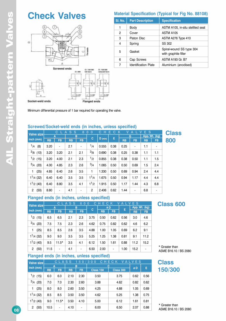
C L A S S 6 0 0 C H E C K V A L V E S Class 600RB FB
Valve size
inch (mm)A B
Cø D E
App. Wt. (kg)
1/2 (15) 6.5 6.5 2.1 2.3 3.75 0.50 0.62 0.56 3.0 4.6
3/4 (20) 7.5 7.5 2.3 2.6 4.62 0.75 0.82 0.62 4.6 6.2
1 (25) 8.5 8.5 2.6 3.5 4.88 1.00 1.05 0.69 6.2 9.1
11/4 (32) 9.0 9.0 3.5 3.5 5.25 1.25 1.38 0.81 9.1 11.2
11/2 (40) 9.5 11.5* 3.5 4.1 6.12 1.50 1.61 0.88 11.2 15.2
2 (50) 11.5 - 4.1 - 6.50 2.00 - 1.00 15.2 -
RB FB
Valve size
inch (mm) A B Cø D E
1/2 (15) 6.0 6.0 2.10 2.30 3.50 3.75 0.62 0.56
3/4 (20) 7.0 7.0 2.30 2.60 3.88 4.62 0.82 0.62
1 (25) 8.0 8.0 2.60 3.50 4.25 4.88 1.05 0.69
11/4 (32) 8.5 8.5 3.50 3.50 4.62 5.25 1.38 0.75
11/2 (40) 9.0 11.5* 3.50 4.10 5.00 6.12 1.61 0.81
2 (50) 10.5 - 4.10 - 6.00 6.50 2.07 0.88
Sl. No. Part Description Specification
1 Body ASTM A105, in-situ stellited seat
2 Cover ASTM A105
3 Piston Disc ASTM A276 Type 410
4 Spring SS 302
5 GasketSpiral-wound SS type 304
with graphite filler
6 Cap Screws ASTM A193 Gr. B7
7 Identification Plate Aluminium (anodised)
Material Specification (Typical for Fig No. 88108)
Sl. No. Part Description Specification
1 Body ASTM A105
2 Bonnet ASTM A105
3 Stem ASTM A479 Type 410
4 Wedge Disc ASTM A217 Gr. CA15
5 Body Seat Ring ASTM A276 Type 410
6 Stem packingGraphite moulded rings withbraided top / bot tom rings
7 GasketSpiral-wound SS type 304
with graphite filler
8 Cap Screws ASTM A193 Gr. B7
9 Gland Bush ASTM A276 Type 410
10 Gland Flange ASTM A105
11 Gland Stud / Nut ASTM A276 Type 410 /ASTM A194 Gr. 2H
12 Yoke Sleeve ASTM A582 Type 416
13 Identification Plate Aluminium (anodised)
14 Handwheel SG Iron / Steel
15 Handwheel Nut Steel
Material Specification (Typical for Fig No. 28101)
* Greater thanASME B16.10 / BS 2080
* Greater thanASME B16.10 / BS 2080
Minimum dif ferential pressure of 1 bar required for operating the valve.
6 7
0706
Screwed/Socket-weld ends (in inches, unless specified)
RB FB RB FB RB FBRB FB RB FB
Valve size
inch (mm) AB C
D (min) EF G App. Wt. (kg)
1/4 (8) 3.20 5.8 - 1/4 - 0.555 0.38 3.25 - 0.25 - 1.7 -
3/8 (10) 3.20 5.8 5.8 3/8 0.690 0.38 3.25 3.25 0.25 0.38 1.7 1.7
1/2 (15) 3.20 5.8 6.4 1/2 0.855 0.38 3.25 4.00 0.38 0.50 1.7 2.4
3/4 (20) 4.00 6.4 7.7 3/4 1.065 0.50 4.00 4.00 0.50 0.69 2.4 3.6
1 (25) 4.85 7.7 9.6 1 1.330 0.50 4.00 5.50 0.69 0.94 3.6 6.8
11/4 (32) 6.40 9.6 9.6 11/4 1.675 0.50 5.50 5.50 0.94 1.17 6.8 6.7
11/2 (40) 6.40 9.6 11.6 11/2 1.915 0.50 5.50 7.25 1.17 1.44 6.7 10.8
2 (50) 8.80 11.6 - 2 - 2.406 0.62 7.25 - 1.44 - 10.8 -
C L A S S 8 0 0 G L O B E V A L V E S
AIL
S
traig
ht-p
attern V
alv
es
AIL
S
traig
ht-p
attern V
alv
es
Class800
Globe ValvesGate Valves
RB FB RB FB
Flanged ends (in inches, unless specified)
RB FBRB FB
C L A S S 6 0 0 G L O B E V A L V E SClass 600RB FB
Valve size
inch (mm)A B
Cø D E
ø F App. Wt. (kg)
1/2 (15) 6.5 6.5 5.8 6.4 3.75 0.50 0.62 0.56 3.25 4.00 3.6 5.4
3/4 (20) 7.5 7.5 6.4 7.7 4.62 0.75 0.82 0.62 4.00 4.00 5.4 7.4
1 (25) 8.5 8.5 7.7 9.6 4.88 1.00 1.05 0.69 4.00 5.50 7.4 11.4
11/4 (32) 9.0 9.0 9.6 9.6 5.25 1.25 1.38 0.81 5.50 5.50 11.4 13.5
11/2 (40) 9.5 11.5* 9.6 11.6 6.12 1.50 1.61 0.88 5.50 7.25 13.5 19.1
2 (50) 11.5 - 11.6 - 6.50 2.00 - 1.00 7.25 - 19.1 -
RB FB
Flanged ends (in inches, unless specified)
Class 150 Class 300
Valve size
inch (mm)A B C
ø D Eø F
1/2 (15) 6.0 6.0 5.80 6.35 3.50 3.75 0.62 0.56 3.25 4.00
3/4 (20) 7.0 7.0 6.35 7.70 3.88 4.62 0.82 0.62 4.00 4.00
1 (25) 8.0 8.0 7.70 9.55 4.25 4.88 1.05 0.69 4.00 5.50
11/4 (32) 8.5 8.5 9.55 9.55 4.62 5.25 1.38 0.75 5.50 5.50
11/2 (40) 9.0 11.5* 9.55 11.60 5.00 6.12 1.61 0.81 5.50 7.25
2 (50) 10.5 - 11.60 - 6.00 6.50 2.07 0.88 7.25 -
C L A S S 1 5 0 / 3 0 0 G L O B E V A L V E S
RB FB
Class150/300 RB FB
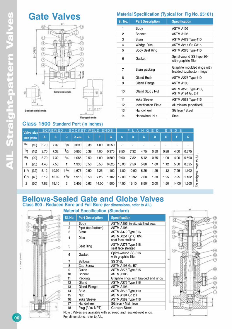
Class 1500 Standard Port (in inches)
Valve size
inch (mm) A B C D (min) E F G A B C D E F G
3/8 (10) 3.70 7.32 3/8 0.690 0.38 4.00 0.250 - - - - - - -
1/2 (15) 3.70 7.32 1/2 0.855 0.38 4.00 0.375 8.50 7.32 4.75 0.50 0.88 4.00 0.375
3/4 (20) 3.70 7.32 3/4 1.065 0.50 4.00 0.500 9.00 7.32 5.12 0.75 1.00 4.00 0.500
1 (25) 4.40 7.50 1 1.330 0.50 5.50 0.625 10.00 7.50 5.88 1.00 1.12 5.50 0.625
11/4 (32) 5.12 10.92 11/4 1.675 0.50 7.25 1.102 11.00 10.92 6.25 1.25 1.12 7.25 1.102
11/2 (40) 5.12 10.92 11/2 1.915 0.50 7.25 1.102 12.00 10.92 7.00 1.50 1.25 7.25 1.102
2 (50) 7.82 19.10 2 2.406 0.62 14.00 1.500 14.50 19.10 8.50 2.00 1.50 14.00 1.500
SCREWED / SOCKET-WELD ENDS
For
wei
ght
s, r
efer
to
AIL
.
F L A N G E D E N D S
Bellows-Sealed Gate and Globe ValvesClass 800 - Reduced Bore and Full Bore (for dimensions, refer to AIL)
Sl. No. Part Description Specification
1 Body ASTM A105
2 Bonnet ASTM A105
3 Stem ASTM A479 Type 410
4 Wedge Disc ASTM A217 Gr. CA15
5 Body Seat Ring ASTM A276 Type 410
6 GasketSpiral-wound SS type 304with graphite filler
7 Stem packingGraphite moulded rings withbraided top/bot tom rings
8 Gland Bush ASTM A276 Type 410
9 Gland Flange ASTM A105
10 Gland Stud / NutASTM A276 Type 410 /ASTM A194 Gr. 2H
11 Yoke Sleeve ASTM A582 Type 416
12 Identification Plate Aluminium (anodised)
13 Handwheel SG Iron / Steel
14 Handwheel Nut Steel
Material Specification (Typical for Fig No. 25101)
Sl. No. Part Description Specification
1 Body ASTM A105, in-situ stellited seat
2 Bonnet ASTM A105
3 Stem ASTM A479 Type 410
4 Plug Disc ASTM A217 Gr. CA15
5 Stem packingGraphite moulded rings with
braided top / bottom rings
6 GasketSpiral-wound SS type 304
with graphite filler
7 Cap Screws ASTM A193 Gr. B7
8 Gland Bush ASTM A276 Type 410
9 Gland Flange ASTM A105
10 Gland Stud / Nut ASTM A276 Type 410 /ASTM A194 Gr. 2H
11 Yoke Bush ASTM A582 Type 416
12 Identification Plate Aluminium (anodised)
13 Handwheel SG Iron / Steel
14 Handwheel Nut Steel
Material Specification (Typical for Fig No. 58108)
* Greater thanASME B16.10 / BS 2080
* Greater thanASME B16.10 / BS 2080
Sl. No. Part Description Specification
1 Body ASTM A105, in-situ stellited seat2 Pipe (top/bot tom) ASTM A1053 Stem ASTM A479 Type 316
4 Disc ASTM A351 Gr. CF8M,seat face stellited
5 Seat Ring ASTM A276 Type 316,seat face stellited
6 Gasket Spiral-wound SS 316with graphite filler
7 Bellows SS 316L8 Cap Screw ASTM A193 Gr. B79 Guide ASTM A276 Type 31610 Bonnet ASTM A10511 Packing Graphite rings with braided end rings12 Gland ASTM A276 Type 31613 Gland Flange ASTM A10514 Stud ASTM A276 Type 41015 Nut ASTM A194 Gr. 2H16 Yoke Sleeve ASTM A582 Type 41617 Handwheel SG Iron / Mall. Iron18 Plug (1/16 NPT) Carbon Steel
Material Specification (Standard)
Note : Valves are available with screwed and socket-weld ends.For dimensions, refer to AIL.

6 7
0706
Screwed/Socket-weld ends (in inches, unless specified)
RB FB RB FB RB FBRB FB RB FB
Valve size
inch (mm) AB C
D (min) EF G App. Wt. (kg)
1/4 (8) 3.20 5.8 - 1/4 - 0.555 0.38 3.25 - 0.25 - 1.7 -
3/8 (10) 3.20 5.8 5.8 3/8 0.690 0.38 3.25 3.25 0.25 0.38 1.7 1.7
1/2 (15) 3.20 5.8 6.4 1/2 0.855 0.38 3.25 4.00 0.38 0.50 1.7 2.4
3/4 (20) 4.00 6.4 7.7 3/4 1.065 0.50 4.00 4.00 0.50 0.69 2.4 3.6
1 (25) 4.85 7.7 9.6 1 1.330 0.50 4.00 5.50 0.69 0.94 3.6 6.8
11/4 (32) 6.40 9.6 9.6 11/4 1.675 0.50 5.50 5.50 0.94 1.17 6.8 6.7
11/2 (40) 6.40 9.6 11.6 11/2 1.915 0.50 5.50 7.25 1.17 1.44 6.7 10.8
2 (50) 8.80 11.6 - 2 - 2.406 0.62 7.25 - 1.44 - 10.8 -
C L A S S 8 0 0 G L O B E V A L V E S
AIL
S
traig
ht-p
attern V
alv
es
AIL
S
traig
ht-p
attern V
alv
es
Class800
Globe ValvesGate Valves
RB FB RB FB
Flanged ends (in inches, unless specified)
RB FBRB FB
C L A S S 6 0 0 G L O B E V A L V E SClass 600RB FB
Valve size
inch (mm)A B
Cø D E
ø F App. Wt. (kg)
1/2 (15) 6.5 6.5 5.8 6.4 3.75 0.50 0.62 0.56 3.25 4.00 3.6 5.4
3/4 (20) 7.5 7.5 6.4 7.7 4.62 0.75 0.82 0.62 4.00 4.00 5.4 7.4
1 (25) 8.5 8.5 7.7 9.6 4.88 1.00 1.05 0.69 4.00 5.50 7.4 11.4
11/4 (32) 9.0 9.0 9.6 9.6 5.25 1.25 1.38 0.81 5.50 5.50 11.4 13.5
11/2 (40) 9.5 11.5* 9.6 11.6 6.12 1.50 1.61 0.88 5.50 7.25 13.5 19.1
2 (50) 11.5 - 11.6 - 6.50 2.00 - 1.00 7.25 - 19.1 -
RB FB
Flanged ends (in inches, unless specified)
Class 150 Class 300
Valve size
inch (mm)A B C
ø D Eø F
1/2 (15) 6.0 6.0 5.80 6.35 3.50 3.75 0.62 0.56 3.25 4.00
3/4 (20) 7.0 7.0 6.35 7.70 3.88 4.62 0.82 0.62 4.00 4.00
1 (25) 8.0 8.0 7.70 9.55 4.25 4.88 1.05 0.69 4.00 5.50
11/4 (32) 8.5 8.5 9.55 9.55 4.62 5.25 1.38 0.75 5.50 5.50
11/2 (40) 9.0 11.5* 9.55 11.60 5.00 6.12 1.61 0.81 5.50 7.25
2 (50) 10.5 - 11.60 - 6.00 6.50 2.07 0.88 7.25 -
C L A S S 1 5 0 / 3 0 0 G L O B E V A L V E S
RB FB
Class150/300 RB FB
Class 1500 Standard Port (in inches)
Valve size
inch (mm) A B C D (min) E F G A B C D E F G
3/8 (10) 3.70 7.32 3/8 0.690 0.38 4.00 0.250 - - - - - - -
1/2 (15) 3.70 7.32 1/2 0.855 0.38 4.00 0.375 8.50 7.32 4.75 0.50 0.88 4.00 0.375
3/4 (20) 3.70 7.32 3/4 1.065 0.50 4.00 0.500 9.00 7.32 5.12 0.75 1.00 4.00 0.500
1 (25) 4.40 7.50 1 1.330 0.50 5.50 0.625 10.00 7.50 5.88 1.00 1.12 5.50 0.625
11/4 (32) 5.12 10.92 11/4 1.675 0.50 7.25 1.102 11.00 10.92 6.25 1.25 1.12 7.25 1.102
11/2 (40) 5.12 10.92 11/2 1.915 0.50 7.25 1.102 12.00 10.92 7.00 1.50 1.25 7.25 1.102
2 (50) 7.82 19.10 2 2.406 0.62 14.00 1.500 14.50 19.10 8.50 2.00 1.50 14.00 1.500
SCREWED / SOCKET-WELD ENDS
For
wei
ght
s, r
efer
to
AIL
.
F L A N G E D E N D S
Bellows-Sealed Gate and Globe ValvesClass 800 - Reduced Bore and Full Bore (for dimensions, refer to AIL)
Sl. No. Part Description Specification
1 Body ASTM A105
2 Bonnet ASTM A105
3 Stem ASTM A479 Type 410
4 Wedge Disc ASTM A217 Gr. CA15
5 Body Seat Ring ASTM A276 Type 410
6 GasketSpiral-wound SS type 304with graphite filler
7 Stem packingGraphite moulded rings withbraided top/bot tom rings
8 Gland Bush ASTM A276 Type 410
9 Gland Flange ASTM A105
10 Gland Stud / NutASTM A276 Type 410 /ASTM A194 Gr. 2H
11 Yoke Sleeve ASTM A582 Type 416
12 Identification Plate Aluminium (anodised)
13 Handwheel SG Iron / Steel
14 Handwheel Nut Steel
Material Specification (Typical for Fig No. 25101)
Sl. No. Part Description Specification
1 Body ASTM A105, in-situ stellited seat
2 Bonnet ASTM A105
3 Stem ASTM A479 Type 410
4 Plug Disc ASTM A217 Gr. CA15
5 Stem packingGraphite moulded rings with
braided top / bottom rings
6 GasketSpiral-wound SS type 304
with graphite filler
7 Cap Screws ASTM A193 Gr. B7
8 Gland Bush ASTM A276 Type 410
9 Gland Flange ASTM A105
10 Gland Stud / Nut ASTM A276 Type 410 /ASTM A194 Gr. 2H
11 Yoke Bush ASTM A582 Type 416
12 Identification Plate Aluminium (anodised)
13 Handwheel SG Iron / Steel
14 Handwheel Nut Steel
Material Specification (Typical for Fig No. 58108)
* Greater thanASME B16.10 / BS 2080
* Greater thanASME B16.10 / BS 2080
Sl. No. Part Description Specification
1 Body ASTM A105, in-situ stellited seat2 Pipe (top/bot tom) ASTM A1053 Stem ASTM A479 Type 316
4 Disc ASTM A351 Gr. CF8M,seat face stellited
5 Seat Ring ASTM A276 Type 316,seat face stellited
6 Gasket Spiral-wound SS 316with graphite filler
7 Bellows SS 316L8 Cap Screw ASTM A193 Gr. B79 Guide ASTM A276 Type 31610 Bonnet ASTM A10511 Packing Graphite rings with braided end rings12 Gland ASTM A276 Type 31613 Gland Flange ASTM A10514 Stud ASTM A276 Type 41015 Nut ASTM A194 Gr. 2H16 Yoke Sleeve ASTM A582 Type 41617 Handwheel SG Iron / Mall. Iron18 Plug (1/16 NPT) Carbon Steel
Material Specification (Standard)
Note : Valves are available with screwed and socket-weld ends.For dimensions, refer to AIL.
8 5
0508
RB FB RB FB
Flanged ends (in inches, unless specified)C L A S S 6 0 0 G A T E V A L V E S
RB FB
Valve size
inch (mm) AB
Cø D E
ø F App. Wt. (kg)
1/2 (15) 6.5 6.0 6.2 3.75 0.50 0.62 0.56 3.25 3.25 3.5 5.1
3/4 (20) 7.5 6.2 7.5 4.62 0.75 0.82 0.62 3.25 4.00 5.1 7.1
1 (25) 8.5 7.5 10.0 4.88 1.00 1.05 0.69 4.00 5.50 7.1 11.3
11/4 (32) 9.0 10.0 10.0 5.25 1.25 1.38 0.81 5.50 5.50 11.3 13.5
11/2 (40) 9.5 10.0 11.4 6.12 1.50 1.61 0.88 5.50 7.25 13.5 19.2
2 (50) 11.5 11.4 - 6.50 2.00 - 1.00 7.25 - 19.2 -
RB FB
RB FB
Flanged ends (in inches, unless specified)
Class 150 Class 300
Valve size
inch (mm) AB C
ø D Eø F
1/2 (15) 5.5 6.0 6.2 3.50 3.75 0.62 0.56 3.25 3.25
3/4 (20) 6.0 6.2 7.5 3.88 4.62 0.82 0.62 3.25 4.00
1 (25) 6.5 7.5 10.0 4.25 4.88 1.05 0.69 4.00 5.50
11/4 (32) 7.0 10.0 10.0 4.62 5.25 1.38 0.75 5.50 5.50
11/2 (40) 7.5 10.0 11.4 5.00 6.12 1.61 0.81 5.50 7.25
2 (50) 8.5 11.4 - 6.00 6.50 2.07 0.88 7.25 -
C L A S S 1 5 0 / 3 0 0 G A T E V A L V E S
RB FB
Screwed/Socket-weld ends (in inches, unless specified)
RB FB RB FB RB FB RB FB
Valve size
inch (mm)A B
C D (min) EG App. Wt. (kg)
1/4 (8) 3.20 - 2.1 - 1/4 0.555 0.38 0.25 - 1.1 -
3/8 (10) 3.20 3.20 2.1 2.1 3/8 0.690 0.38 0.25 0.38 1.1 1.1
1/2 (15) 3.20 4.00 2.1 2.3 1/2 0.855 0.38 0.38 0.50 1.1 1.5
3/4 (20) 4.00 4.85 2.3 2.6 3/4 1.065 0.50 0.50 0.69 1.5 2.4
1 (25) 4.85 6.40 2.6 3.5 1 1.330 0.50 0.69 0.94 2.4 4.4
11/4 (32) 6.40 6.40 3.5 3.5 11/4 1.675 0.50 0.94 1.17 4.4 4.4
11/2 (40) 6.40 8.80 3.5 4.1 11/2 1.915 0.50 1.17 1.44 4.3 6.8
2 (50) 8.80 - 4.1 - 2 2.406 0.62 1.44 - 6.8 -
C L A S S 8 0 0 C H E C K V A L V E S
RB FB
Flanged ends (in inches, unless specified)
Class 150 Class 300
C L A S S 1 5 0 / 3 0 0 C H E C K V A L V E S
Screwed/Socket-weld ends (in inches, unless specified)
RB FB RB FB RB FBRB FB RB FB
Valve size
inch (mm) AB C
D (min) EF G App. Wt. (kg)
1/4 (8)** 3.15 6.0 - 1/4 - 0.555 0.38 3.25 - 0.25 - 1.6 -
3/8 (10) 3.15 6.0 6.0 3/8 0.690 0.38 3.25 3.25 0.25 0.38 1.6 1.6
1/2 (15) 3.15 6.0 6.2 1/2 0.855 0.38 3.25 3.25 0.38 0.50 1.6 2.0
3/4 (20) 3.35 6.2 7.5 3/4 1.065 0.50 3.25 4.00 0.50 0.71 2.0 3.1
1 (25) 3.94 7.5 10.0 1 1.330 0.50 4.00 5.50 0.71 0.94 3.1 6.1
11/4 (32) 4.70 10.0 10.0 11/4 1.675 0.50 5.50 5.50 0.94 1.19 6.1 6.0
11/2 (40) 4.70 10.0 11.4 11/2 1.915 0.50 5.50 7.25 1.19 1.44 6.0 9.1
2 (50)** 5.12 11.4 - 2 - 2.406 0.62 7.25 - 1.44 - 9.1 -
C L A S S 8 0 0 G A T E V A L V E S
AIL
S
traig
ht-p
attern V
alv
es
AIL
S
traig
ht-p
attern V
alv
es
Gate Valves
Class800
Class 600
Class 150/300
Class800
Class150/300
Check Valves
Flanged ends (in inches, unless specified)
RB FB RB FBRB FB
C L A S S 6 0 0 C H E C K V A L V E S Class 600RB FB
Valve size
inch (mm)A B
Cø D E
App. Wt. (kg)
1/2 (15) 6.5 6.5 2.1 2.3 3.75 0.50 0.62 0.56 3.0 4.6
3/4 (20) 7.5 7.5 2.3 2.6 4.62 0.75 0.82 0.62 4.6 6.2
1 (25) 8.5 8.5 2.6 3.5 4.88 1.00 1.05 0.69 6.2 9.1
11/4 (32) 9.0 9.0 3.5 3.5 5.25 1.25 1.38 0.81 9.1 11.2
11/2 (40) 9.5 11.5* 3.5 4.1 6.12 1.50 1.61 0.88 11.2 15.2
2 (50) 11.5 - 4.1 - 6.50 2.00 - 1.00 15.2 -
RB FB
Valve size
inch (mm) A B Cø D E
1/2 (15) 6.0 6.0 2.10 2.30 3.50 3.75 0.62 0.56
3/4 (20) 7.0 7.0 2.30 2.60 3.88 4.62 0.82 0.62
1 (25) 8.0 8.0 2.60 3.50 4.25 4.88 1.05 0.69
11/4 (32) 8.5 8.5 3.50 3.50 4.62 5.25 1.38 0.75
11/2 (40) 9.0 11.5* 3.50 4.10 5.00 6.12 1.61 0.81
2 (50) 10.5 - 4.10 - 6.00 6.50 2.07 0.88
Sl. No. Part Description Specification
1 Body ASTM A105, in-situ stellited seat
2 Cover ASTM A105
3 Piston Disc ASTM A276 Type 410
4 Spring SS 302
5 GasketSpiral-wound SS type 304
with graphite filler
6 Cap Screws ASTM A193 Gr. B7
7 Identification Plate Aluminium (anodised)
Material Specification (Typical for Fig No. 88108)
Sl. No. Part Description Specification
1 Body ASTM A105
2 Bonnet ASTM A105
3 Stem ASTM A479 Type 410
4 Wedge Disc ASTM A217 Gr. CA15
5 Body Seat Ring ASTM A276 Type 410
6 Stem packingGraphite moulded rings withbraided top / bot tom rings
7 GasketSpiral-wound SS type 304
with graphite filler
8 Cap Screws ASTM A193 Gr. B7
9 Gland Bush ASTM A276 Type 410
10 Gland Flange ASTM A105
11 Gland Stud / Nut ASTM A276 Type 410 /ASTM A194 Gr. 2H
12 Yoke Sleeve ASTM A582 Type 416
13 Identification Plate Aluminium (anodised)
14 Handwheel SG Iron / Steel
15 Handwheel Nut Steel
Material Specification (Typical for Fig No. 28101)
* Greater thanASME B16.10 / BS 2080
* Greater thanASME B16.10 / BS 2080
Minimum dif ferential pressure of 1 bar required for operating the valve.
4 9
Salient features• Bolted body-bonnet design for valves up to Class 800.
Valves with welded bonnet also available on request• Screwed with seal-welded body-bonnet design
for valves of Class 1500• Bellows-sealed Gate and Globe valves available in Class 800• Bolted body-bonnet joints provided with spiral-wound
stainless steel gasket and graphite filler for maximumprotection against leaks
• Die-formed graphite inner packing rings and braidedgraphite end rings with Inconel wire reinforcement andcorrosion inhibitor
• T-head stem-disc connection of gate valve fully meetsstrength requirements of API 602 and API 598
• Rolled ACME thread on stem for smooth operation• Tapered shoulder on the stem for back seating• Self-aligning type gland assembly with stud-and-nut
tightening• Integral hard-faced body seat for globe and check valves• Spring-loaded disc on check valves suitable for non-
horizontal applications too• Gate and globe valves can be of fered with electrical
actuators• Austenitic SS forging for body and bonnet of Cryogenic
valves, resulting in excellent impact strength, minimal heatloss and resistance to corrosion
• Valves can be of fered to NACE MR-0175 and other specialNACE requirements
• Valves can be supplied with IBR certification
AIL
S
traig
ht-p
attern V
alv
es
04
AIL
S
traig
ht-p
attern V
alv
es
09
Other materials of construction such as F316L / F304L also available.
Body & Bonnet/Cover Trim numbers
ASTM A105 01 / 08 / 05
ASTM A182 Gr. F5 08 / 05
ASTM A182 Gr. F9 08 / 05
ASTM A182 Gr. F11 08 / 05
ASTM A182 Gr. F22 08 / 05
ASTM A182 Gr. F304 02 / 15
ASTM A182 Gr. F316 10 / 12 / 16
ASTM A350 Gr. LF2 08 / 16
Body and Trim Combinations
Trim Materials
Trim No.Valve Type
Stem Seating Surfaces
(API 602) Material Disc Body Seat
01 Gate Valves ASTM A479 Type 410 13% Cr. Steel 13% Cr. Steel
05 Gate, Globe and Check Valves ASTM A479 Type 410 HF HF
08 Gate, Globe and Check Valves ASTM A479 Type 410 13% Cr. Steel HF
02 Gate Valves ASTM A479 Type 304 SS 304 SS 304
10 Gate Valves ASTM A479 Type 316 SS 316 SS 316
12 Gate, Globe and Check Valves ASTM A479 Type 316 SS 316 HF
15 Gate, Globe and Check Valves ASTM A479 Type 304 SS 304 + HF HF
16 Gate, Globe and Check Valves ASTM A479 Type 316 SS 316 + HF HF
HF - Hard Faced with Cobalt-Chromium-Tungsten alloy (Stellite #6)
Cryogenic Gate Valves
Cryogenic Globe Valves
Sl. No. Part Description Specification
1 Body ASTM A182 Gr. F304/F3162 Cover Flange ASTM A182 Gr. F304/F3163 Extension Column ASTM A312 Gr. TP304L/316L4 Bonnet ASTM A182 Gr. F304/F3165 Cap Screw ASTM A320 Gr. B8 Cl. 26 Stem ASTM A479 Gr. 304/316
7 Wedge Disc ASTM A351 Gr. CF8/CF8M withsuitable seating surface
8 Body Seat Ring Type 304/316 withsuitable seating surface
9 Gasket Spiral-wound SS type 304with graphite filler
10 Stem packing Graphite moulded rings withbraided top/bottom rings
11 Gland Bush Type 304/316 SS12 Gland Flange ASTM A182 Gr. F304/F316
13 Gland, Stud and Nut ASTM A320 Gr. B8 Cl. 2/ASTM A194 Gr. 8
14 Yoke Sleeve Type 416 SS
15 Thrust WasherSintered Bronze/SS-backed PTFE/CS-backed PTFE
16 Identification Plate Aluminium (anodised)17 Handwheel SG Iron / Steel18 Handwheel Nut Steel
Material Specification (Standard)
Sl. No. Part Description Specification
1 BodyASTM A182 Gr. F304/F316,in-situ stellited seat
2 Cover Flange ASTM A182 Gr. F304/F3163 Extension Column ASTM A312 Gr. TP304L/316L4 Bonnet ASTM A182 Gr. F304/F3165 Cap Screw ASTM A320 Gr. B8 Cl. 26 Stem ASTM A479 Gr. 304/316
7 Plug Disc ASTM A351 Gr. CF8/CF8M withsuitable seating surface
8 Gasket Spiral-wound SS type 304with graphite filler
9 Stem packing Graphite moulded rings withbraided top/bottom rings
10 Gland Bush Type 304/316 SS11 Gland Flange ASTM A182 Gr. F304/F316
12 Gland, Stud and Nut ASTM A320 Gr. B8 Cl. 2/ASTM A194 Gr. 8
13 Yoke Bush Type 416 SS
14 Identification Plate Aluminium (anodised)15 Handwheel SG Iron / Steel16 Handwheel Nut Steel
Material Specification (Standard)
Screwed/Socket-weld ends (in inches, unless specified)C L A S S 8 0 0 C R Y O G A T E / G L O B E V A L V E S
RB FB
GATE GLOBEGATE
GLOBE
Class 800
RB FBRB FBRB FB
GATE GLOBE
RB FB RB FB RB FB
Valve sizeinch (mm)
A B
C D (min) E F G F G
1/2 (15) 3.94 3.20 4.00 17.1 17.1 16.2 16.7 1/2 0.855 0.38 3.25 3.25 0.38 0.50 3.25 4.00 0.38 0.50
3/4 (20) 3.94 4.00 4.85 17.1 17.1 16.7 17.0 3/4 1.065 0.50 3.25 4.00 0.50 0.71 4.00 4.00 0.50 0.69
1 (25) 3.94 4.85 6.40 17.1 20.7 17.0 20.0 1 1.330 0.50 4.00 5.50 0.71 0.94 4.00 5.50 0.69 0.94
11/4 (32) 4.70 6.40 6.40 20.7 20.7 20.0 20.0 11/4 1.675 0.50 5.50 5.50 0.94 1.19 5.50 5.50 0.94 1.17
11/2 (40) 4.70 6.40 8.80 20.7 22.1 20.0 21.8 11/2 1.915 0.50 5.50 7.25 1.19 1.44 5.50 7.25 1.17 1.44
2 (50) 5.12 8.80 - 22.1 - 21.8 - 2 2.406 0.62 7.25 - 1.44 - 7.25 - 1.44 -
Cryogenic valves are also available in Class 150, 300, 600 and 1500, with dimensions generally as percorresponding gate/globe valves in pages 5 - 7. For detailed dimensions, refer to AIL.
Straight-pattern Gate/Globe/Check Valves
AIL Forged Steel Valves are of fered with trims shown below, to suit a variety of services.

10 3
Technic
al
Inform
atio
n
03
AIL
Y-p
attern V
alv
es
10
AIL Forged Steel Y-pat tern Globe and Check
Valves have established themselves in the industry
for their rugged and compact design, and reliable
service. These valves are of fered in Carbon Steel andAlloy Steel. They are available in a range of sizes
starting from 1/4” to 2” (in reduced-bore design) and
from 3/8” to 11/2” (in full-bore design).
The rugged construction ensures an ideal body and
bonnet, suited to handle high pressure andtemperatures - up to 4250C in carbon steel and 5400C
in alloy steel.
The Y-pattern design ensures a near-per fect straight
flow which significantly reduces pressure drop and
turbulence when compared to conventional designs.
As a standard, valves are supplied with screwed body-
bonnet joint, which ensures ease of inspection and
in-line maintenance, thus minimising downtime.
AIL Y-pattern valves can be of fered to NACE MR-0175 andother special NACE requirements. They can also be
supplied with IBR certification.
Familiarity with our catalogue numbering is not necessary when specifying or ordering our valves. A fulldescription of the valve provided by you is translated into a catalogue number as per the system shown.
For any other special requirement, add SPL to the catalogue number and provide details.
Y-pattern Globe/Check Valves
Y-pattern Globe ValvesDisc and SeatThe disc is provided with two integral rings to guide it throughoutits travel in the body. This minimises side thrust on the disc andeliminates bending of the stem even at high flow velocities. Bodyand disc seats are hard-faced to ensure a long, trouble-free lifecycle.
Disc-Stem ConnectionThe unique joint at the discand the stem provides for aflexible yet strong connectionthat enables the disc to freelyfloat on the stem. This resultsin perfect alignment of the discwith the stem.
Body-Bonnet JointThe bonnet is screwed to the body with ACME threads to ensureease of dismantling and resistance to galling. A graphite gasketis provided for tight sealing. This joint is tack-welded to preventloosening while in service. The bonnet can be easily removedfor inspection and maintenance of inner parts. The joint canalso be seal-welded on request.
PackingDie-moulded graphite rings are used as packing to provide foroptimal per formance at high pressures and temperatures. Twofilament rings provided at the top and bot tom of the graphitepacking rings act as anti-extrusion rings. Moreover, a smoothsurface finish on the stuf fing box along with a precision-machinedstem ensure optimum sealing and packing life.
StemThe stem is ACME-threaded and is ground for smooth operation.
Gland ArrangementThe two-piece ball-type gland flange arrangementensures uniform loading on the packing even incase the gland is unevenly tightened.
InstallationGlobe valves can be installed, either with the flowover or under the disc, depending on the servicecondition. However, in the case of steam and othersuch hot services that include drain lines, globevalves ought to be installed with flow over the discto aver t unseating caused as an ef fect ofdif ferential thermal expansion that would otherwiseresult in leakage and consequent wire drawing.
End ConnectionSocket-weld ends to ASME B16.11But t-weld ends to BS 5352 Annexure DScrewed ends (NPT) to ASME B1.20.1
Bore DiameterBoth Class 1500 and Class 2500 valves have borediameters conforming to Class 1500-StandardBore of BS 5352, with the exception of 15mm Class2500 valve which has a bore diameter of 14.5mm.
Y-pattern Check ValvesY-pat tern Check Valves incorporate the samedesign and construction features as their globevalve counterpar ts. The spring-loaded discminimises chat tering and enables the valve to beinstalled either in a horizontal or vertical position.
Size Valve type Pressure Class End Connection Trim Body material
15 - 15mm
20 - 20mm
25 - 25mm
40 - 40mm
50 - 50mm
6 - Scr. Bonnet7 - Seal-welded
Bonnet
GLOBE 15- Class 150025- Class 2500
3 - Butt-weld4 - Screwed NPT5 - Socket-weld
U - Hardfacedseatingsur face
NIL - A105F11F22
8 - Scr. Cap9 - Seal-welded
Cap
F316F316LF347
NIL - StandardIBR - IBR-cer tified
Options
CHECK
Ordering Information - Y-pat tern Valves
Compliance Standards
BS 6364API 598 BS 5352
Valve Type Valve DesignFace-to-face
End ConnectionPressure / Temp. Valve inspection
dimension rating** and testing
Gate ValvesAPI 602 API 598
ASME B16.34 BS 5352
Globe and BS 5352 API 598Check Valves
BS 5352*ASME B16.34 BS 5352
Cryo Gate &BS 6364
Globe ValvesBS 6364
Y-Globe and ASME B16.34ASME 16.34 API 598
Check Valves MSS SP 84
AIL Standard(screwed/socket-weld/
butt-weld)
ASME B16.10BS 2080(flanged)
ASME B1.20.1 (NPT) • BS 21 / ISO 7(screwed - taper)
ASME B16.5 RF 125-250 Ra(flanged)
AIL Standard
ASME B16.11(socket-weld)
BS 2779 / ISO 228 • BS 21 / ISO 7(screwed - parallel)
API 602*BS 5352
For Class 150 valves, the flange drilling dimensions will be as per Class 150 and all other dimensions as per Class 300.End flanges are welded onto the body.Bellows-Sealed Gate and Globe valves conform to BS 5352.Socket-weld Class 800 Reduced Bore valves conform to Class 3000 (or Sch.80/Sch.XS) fit tings of ASME B16.11.Socket-weld Class 800 Full Bore valves conform to Class 6000 (or Sch.160) fit tings of ASME B16.11.Socket-weld Class 1500 Standard Port valves conform to Class 9000 (or Sch.XXS) fit tings of ASME B16.11.*Full Bore design also conforms to ASME B16.34 ** API 602/BS 5352 for Class 800 and ASME B16.34 for Class 150/300/600/1500/2500.
see page 10
ValveType
ASMEClass
H Y D R O S T A T I C A I R
Shell Back SeatSeat Closure
High Pressure Low PressureSeat
psi kg/cm2 psi kg/cm2 psi kg/cm2 psi kg/cm2 psi kg/cm2
150 450 32 315 22 - - - - 90 6.3300 1125 79 815 57 - - - - 90 6.3600 2225 156 1630 115 - - - - 90 6.3800 3000 211 2200 155 - - - - 90 6.31500 5575 392 4080 287 - - - - 90 6.3150 450 32 315 22 315 22 - - 90 6.3300 1125 79 815 57 815 57 - - 90 6.3600 2225 156 1630 115 1630 115 - - 90 6.3800 3000 211 2200 155 2200 155 - - 90 6.3150 450 32 - - 315 22 80 6 - -300 1125 79 - - 815 57 210 15 - -600 2225 156 - - 1630 115 410 29 - -800 3000 211 - - 2200 155 550 39 - -
800 3000 211 2200 155 - - - - 90 6.3
800 3000 211 2200 155 2200 155 - - 90 6.3
Gate
Globe
Check
B’SealedGate
B’SealedGlobe
Pressure testing as per API 598 - for ASTM A105 and LF2*
* Test pressure values are for ASTM A105 and LF2 materials of construction.For other materials, substitute corresponding figures from the table alongside. Forcheck valves, low pressure hydrostatic closure test is carried out at 25% of the highpressure closure test.
Working Pressure (in psi)
150Shell 450 425 350
Seat 320 305 255
300Shell 1125 1100 900
Seat 825 795 660
600Shell 2250 2175 1800
Seat 1650 1585 1320
800Shell 3000 2900 2400
Seat 2200 2115 1760
1500Shell 5625 5400 4500
Seat 4125 3960 3300
ASME
Class F5,F9
F11,F22
F304,F316,F321,F347
F304L,
F316L
- for other materials
Ordering Information - Straight-pat tern Valves
Trim
NIL - A105LF2F5F11F22F304 / F304LF316 / F316LF347Monel
Body Material
NIL - Reduced / Standard BoreFB - Full Bore
WB - Welded BonnetLA - Locking ArrangementE - Electrical Actuator
BS - Bellows-SealedCR - Cryogenic
Options
1 - Screwed NPT2 - Socket-weld3 - Flanged4 - Screwed BSP
parallel5 - Screwed BSP
taper
End Connection
1 - Class 1503 - Class 3005 - Class 15006 - Class 6008 - Class 800
Pressure Class
2 - Gate5 - Globe8 - Check
Valve Type
1/4”3/8”1/2”3/4”1”
11/4”11/2”
2”
Size
01 - 13% Cr.05 - HF08 - 13% Cr. HF
API Trim Nos.10, 12, etc.,
also available

2 11
Introductio
n AIL Forged Steel Gate, Globe and Check Valves have established themselves the world over for their quality, reliability and
long service. Rugged and compact in design, these valves are manufactured to the latest international designs using advanced
manufacturing techniques and stringent quality control checks. The valves are regularly supplied to major Indian and international
clients including oil refining companies and EPC contractors. They are available in a range of sizes starting from 1/4” to 2” (inreduced-bore design) and from 3/8” to 11/2” (in full-bore design).
AUDCO INDIA LIMITED (AIL) is a leading valve manufacturer, with a strong presence in India and overseas. AIL has three
manufacturing facilities located in Southern India. The main plant is located in Manapakkam, Chennai. The two other plants
are at Maraimalai Nagar, 40 kilometres south and at Kancheepuram, 70 kilometres west of the main plant. The plants are
equipped with modern manufacturing facilities with special-purpose machines, automatic welding equipment, heat treatmentfurnaces and testing equipment for total control of all manufacturing operations. In-house metallurgical and NDE laboratories,
and calibration facilities with modern equipment provide support to ensure the quality of products manufactured. AIL
manufactures a wide variety of industrial valves. The Quality Management System in all three plants is certified to ISO 9001:2000
System.
02
Chennai plant
QQuality Policy
Audco India Limited is committed to
Total Customer Satisfaction
We achieve this by
• Maintaining a high standard of
quality consistent with the customer
requirements
• Complying with the Codes,
S t a n d a r d s , C u s t o m e r
Specifications, Statutor y and
Regulator y requirements as
applicable to our Products
• Continually improving the
ef fectiveness of Qualit y
Management System to add value
to our Products
AIL
Y-p
attern V
alv
es
11
ValveClass 1500 Class 2500
Size A B C D E F App.Wt. A B C D E F App.Wt.(kg) (kg)
15 97.5 22021.72
9.7 128 1/2”-14NPT 6 115 24521.72
9.7 135 1/2”-14NPT 722.23 22.23
20 115 24527.05
12.7 135 3/4”-14NPT 7 115 24527.05
12.7 135 3/4”-14NPT 727.56 27.56
25 138 29533.78
12.7 165 1”-11.1/2NPT 10 138 29533.78
12.7 165 1”-11.1/2NPT 1034.29 34.29
40 185 39248.64
12.7 238 11/2”-11.1/2NPT 19 202 41548.64
12.7 255 11/2”-11.1/2NPT 2549.15 49.15
50 185 39261.11
16.0 238 2”-11.1/2NPT 19 202 41561.11
16.0 255 2”-11.1/2NPT 2561.62 61.62
Dimensional details (in mm, unless specified)
ValveClass 1500 Class 2500
Size A B C D E App.Wt. A B C D E App.Wt.(kg) (kg)
15 97.5 7121.72
9.7 1/2”-14NPT 2 115 8521.72
9.7 1/2”-14NPT 2.522.23 22.23
20 115 8527.05
12.7 3/4”-14NPT 2.5 115 8527.05
12.7 3/4”-14NPT 2.527.56 27.56
25 138 9533.78
12.7 1”-11.1/2NPT 5 138 9533.78
12.7 1”-11.1/2NPT 534.29 34.29
40 185 12048.64
12.7 11/2”-11.1/2NPT 9 202 13548.64
12.7 11/2”-11.1/2NPT 949.15 49.15
50 185 12061.11
16.0 2”-11.1/2NPT 9 202 13561.11
16.0 2”-11.1/2NPT 961.62 61.62
Dimensional details (in mm, unless specified)
Note : 40mm valves can be of fered with butt-weld and socket-weld ends to suit 32mm pipe. 50mm valves can be of fered with butt-weld ends to suit 65mm pipe. Class 900 valves available on request.
AIL Manufacturing Programme
DE
SI
GN
S
TA
ND
AR
DA
PI 6
02 /
BS
535
2B
S 53
52A
SM
E B
16.3
4/M
SS
SP
84
Valve End ASME1/4” 3/8” 1/2” 3/4” 1” 11/4”11/2” 2”Type Conn. Class
screwed/800
RB � � � � � � � �
sock.wld FB � � � � � �
sock.wld 1500 SP � � � � � � �
150RB � � � � � �
FB � � � � �
flanged 300RB � � � � � �
FB � � � � �
600RB � � � � � �
FB � � � � �
screwed/800
RB � � � � � � � �
sock.wld FB � � � � � �
150RB � � � � � �
FB � � � � �
flanged 300RB � � � � � �
FB � � � � �
600RB � � � � � �
FB � � � � �
800RB � � � � � �
screwed/ FB � � � � �
sock.wld800
RB � � � � � �
FB � � � � �
screwed/800
RB � � � � � �
sock.wld FB � � � � �
150RB � � � � � �
flanged FB � � � � �
300RB � � � � � �
FB � � � � �
600RB � � � � � �
FB � � � � �
screwed/1500 FB � � � � � �
sock.wld/2500 FB � � � � � �
but t.wld1500 FB � � � � � �
2500 FB � � � � � �
CryogenicGate & Globe
Valves
Globe & CheckValves
Y-patternGlobe Valves
BS
636
4
Y-patternCheck Valves
Sl. No. Part Description Specification
1 Body & BonnetCarbon Steel Alloy Steel
2 Cap
3 Disc Type 410 SS, in-situ stellited seat
4 Spring Nimonic 90 / Inconel X 750
5 Gasket Graphite
Material Specification
ASTM A105 orIS 1875 Cl. 2
ASTM A182Gr. F22
ASTM A182 Gr.F22,in-situ stellited seat
ASTM A105,in-situ stellited seat
End dimensions of 50mm valves can be machined to suit 65mm pipe. For details, refer to AIL.Class 900 valves available on request. For dimensions, refer to AIL.
Gate Valves
Bellows-SealedGate Valves
RB - Reduced Bore - bore conforms to BS 5352 Reduced Bore and API 602 Standard Port
FB - Full Bore - bore conforms to BS 5352 Standard Bore
SP - Standard Port - bore conforms to API 602 Standard Port
Bellows-SealedGlobe Valves
AP
I602
BS
5352
Y-pattern Globe Valves
Sl. No. Part Description Specification
1 & 2 Body & BonnetCarbon Steel Alloy Steel
3 Yoke Bush ASTM A439 Type D2
4 Disc Type 410 SS, in-situ stellited seat
5 Stem Type 410 SS
6 Stem packing Graphite with braided end rings
7 Handwheel SG Iron
8 Gland Type 410 SS
9 Gland Flange BS 970 : 709M40 COND R
10 Handwheel Nut Steel
11 Gland Stud ASTM A193 Gr. B7
12 Gland Stud Nut ASTM A194 Gr. 2H
13 Gasket Graphite
Material Specification
ASTM A182 Gr.F22,in-situ stellited seat
ASTM A105,in-situ stellited seat
Y-pattern Check Valves
12 1
API 602 • BS 5352
BS 6364
ASME B16.34 • MSS SP 84
PB No. : C1110-0/12.04 (supersedes C1096-0/06.00)As we continuously endeavour to improve our products, the data given herein are subject to change without notice.
AUDCO INDIA LIMITEDAdministrative Of fice
Mount-Poonamallee Road, Manapakkam, Post Bag 976, Chennai 600 089, INDIA.Tel : (044) 22492323. Fax : (044) 22495055, 22494055.Website : www.ailvalves.com
Manufacturing Plants
Mount-Poonamallee Road, Manapakkam, Chennai 600 089, INDIA.Enathur, Kancheepuram 631 552, INDIA.B8, MMDA Industrial Area, Maraimalai Nagar 603 209, INDIA.
Marketed by
LARSEN & TOUBRO LIMITEDValves Business Unit
Post Bag 5247, Chennai 600 002, INDIA. Tel : (044) 28462015-19. Fax : (044) 28462102/03.P.O. Box 619, Kolkata 700 071, INDIA. Tel : (033) 22822435/22823301. Fax : (033) 22828406.P.O. Box 8901, Mumbai 400 072, INDIA. Tel : (022) 28581118/28581432. Fax : (022) 28581027.P.O. Box 6223, New Delhi 110 015, INDIA. Tel : (011) 51419579-83. Fax : (011) 51419596.
AUDCO INDIA LIMITED
Kancheepuram plant
Maraimalai Nagar plant
AIL FORGED STEEL
GATE, GLOBE & CHECK
VALVES
ASME Class 150 - 2500
8mm - 50mm (1/4” - 2”)