14. airplane geometry - rose-hulman institute of …luic/me427/gambit/tutorial 9 - airplane... ·...
TRANSCRIPT
AIRPLANE GEOMETRY
© Fluent Inc., Mar-06 14-1
14. AIRPLANE GEOMETRY
In this tutorial you will import a STEP file that describes the geometry of an airplane
body, including the wing and nacelle that houses the engine. You will clean up the
geometry using GAMBIT smooth/heal and cleanup tools, apply three different types of
size functions, and mesh the geometry using a tetrahedral meshing scheme.
In this tutorial you will learn how to:
• Import a STEP file
• Use a smooth-heal operation to repair the imported geometry
• Use several clean-up operations to clean up the geometry
• Construct a flow volume around the airplane geometry
• Apply size functions to control mesh quality
• Mesh faces using a triangular pave meshing scheme
• Mesh a volume using a tetrahedral meshing scheme
• Prepare the mesh to be read into FLUENT 5/6
14.1 Prerequisites
This tutorial assumes you have worked through Tutorials 1, 6, and 13 and are familiar
with use of the GAMBIT GUI and general clean-up operations.
Problem Description AIRPLANE GEOMETRY
14-2 © Fluent Inc., Mar-06
14.2 Problem Description
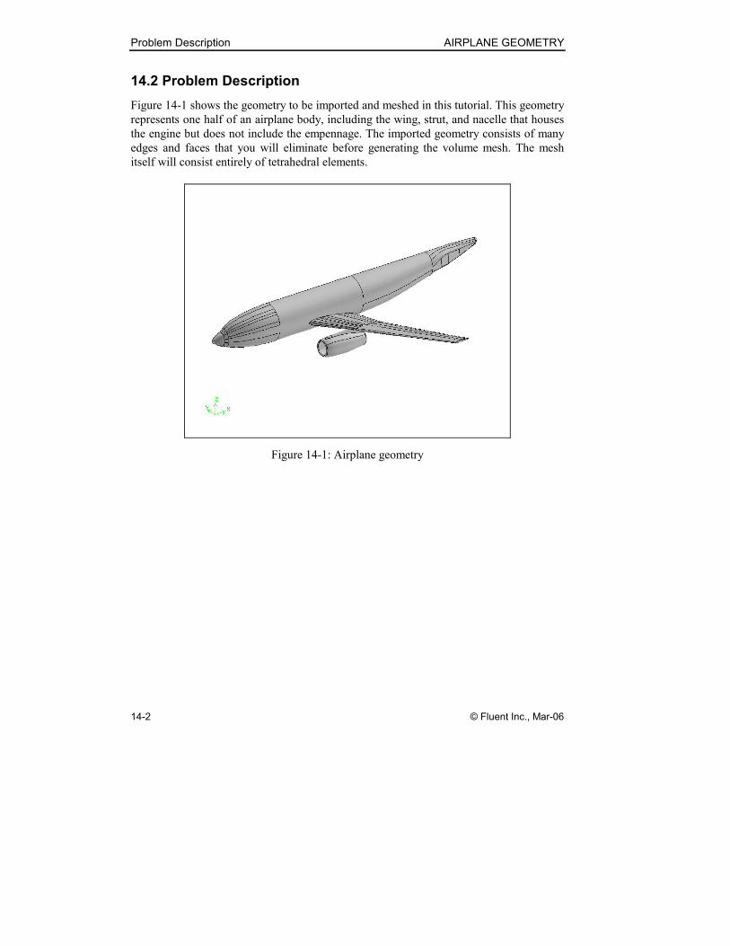
Figure 14-1 shows the geometry to be imported and meshed in this tutorial. This geometry
represents one half of an airplane body, including the wing, strut, and nacelle that houses
the engine but does not include the empennage. The imported geometry consists of many
edges and faces that you will eliminate before generating the volume mesh. The mesh
itself will consist entirely of tetrahedral elements.
Figure 14-1: Airplane geometry
AIRPLANE GEOMETRY Strategy
© Fluent Inc., Mar-06 14-3
14.3 Strategy
In this tutorial, you will create a tetrahedral mesh in a flow volume surrounding one half
of an airplane body, including the wing, strut, and nacelle housing the engine but
excluding the empennage. The geometry will be imported as a STEP file containing many
faces and edges that will need to be eliminated before meshing. After creating a flow
volume around the imported geometry and using a GAMBIT smooth/heal operation to
simplify the geometry, you will clean up the geometry using the cleanup tools available in
GAMBIT. You will then create triangular face meshes on the airplane body surfaces and
flow-volume symmetry plane and mesh the flow volume with tetrahedral elements.
NOTE: This tutorial employs a relatively course mesh so that the mesh characteristics can
be easily examined. In actual practice, the model described in this tutorial would employ a
much finer mesh than is used here, especially in the regions adjacent to the airplane body.
Procedure AIRPLANE GEOMETRY
14-4 © Fluent Inc., Mar-06
14.4 Procedure
1. Copy the file
path/Fluent.Inc/gambit2.x/help/tutfiles/airplane.stp
(where 2.x is the GAMBIT version number) from the GAMBIT installation area in
the directory path to your working directory.
2. Start GAMBIT using the session identifier “Airplane”.
Step 1: Select a Solver
1. Choose the solver from the main menu bar:
Solver → FLUENT 5/6
The choice of a solver dictates the options available in various forms (for
example, the boundary types available in the Specify Boundary Types form). For
some systems, FLUENT 5/6 is the default solver. The solver currently selected is
shown at the top of the GAMBIT GUI.
AIRPLANE GEOMETRY Procedure
© Fluent Inc., Mar-06 14-5
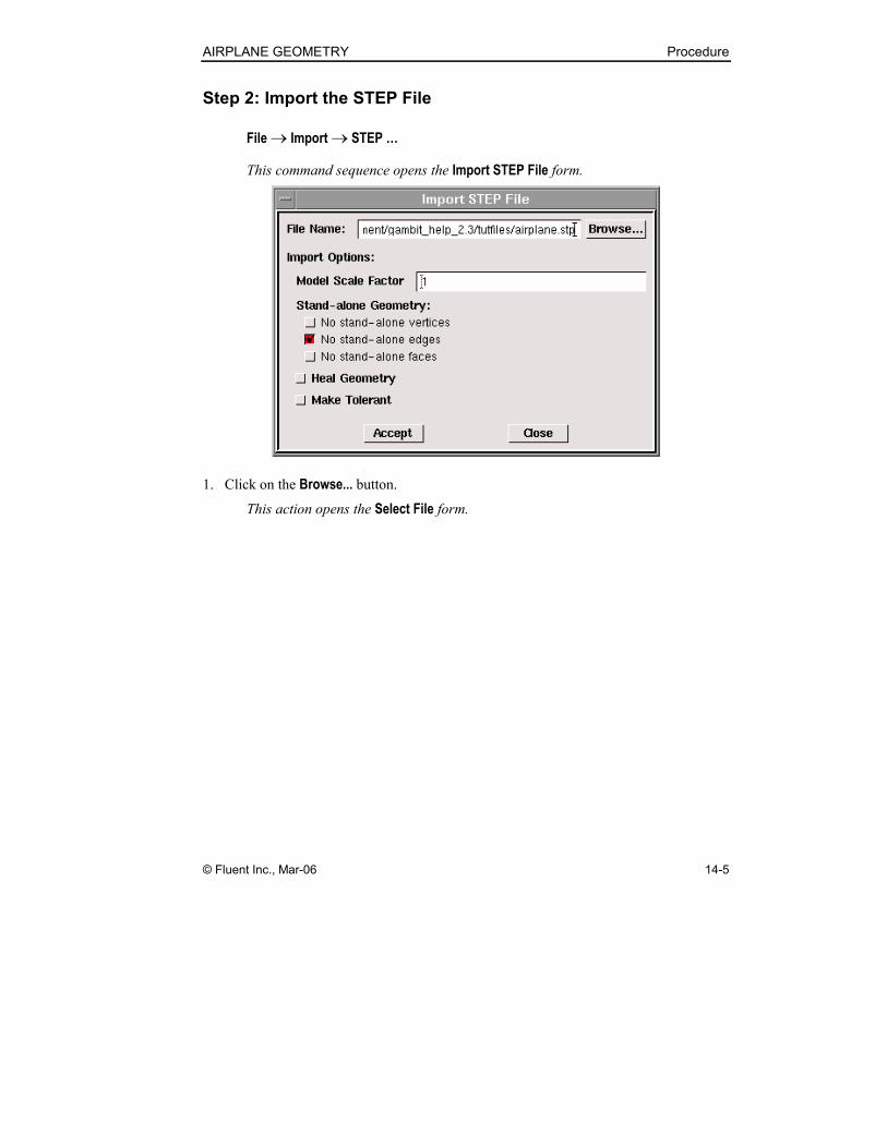
Step 2: Import the STEP File
File → Import → STEP …
This command sequence opens the Import STEP File form.
1. Click on the Browse... button.
This action opens the Select File form.
Procedure AIRPLANE GEOMETRY
14-6 © Fluent Inc., Mar-06
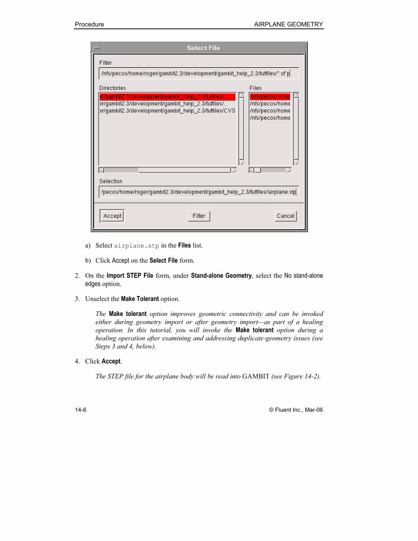
a) Select airplane.stp in the Files list.
b) Click Accept on the Select File form.
2. On the Import STEP File form, under Stand-alone Geometry, select the No stand-alone
edges option.
3. Unselect the Make Tolerant option.
The Make tolerant option improves geometric connectivity and can be invoked
either during geometry import or after geometry import—as part of a healing
operation. In this tutorial, you will invoke the Make tolerant option during a
healing operation after examining and addressing duplicate-geometry issues (see
Steps 3 and 4, below).
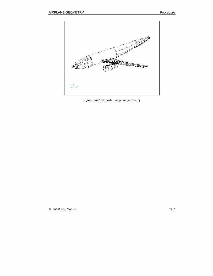
4. Click Accept.
The STEP file for the airplane body will be read into GAMBIT (see Figure 14-2).
AIRPLANE GEOMETRY Procedure
© Fluent Inc., Mar-06 14-7
Figure 14-2: Imported airplane geometry
Procedure AIRPLANE GEOMETRY
14-8 © Fluent Inc., Mar-06
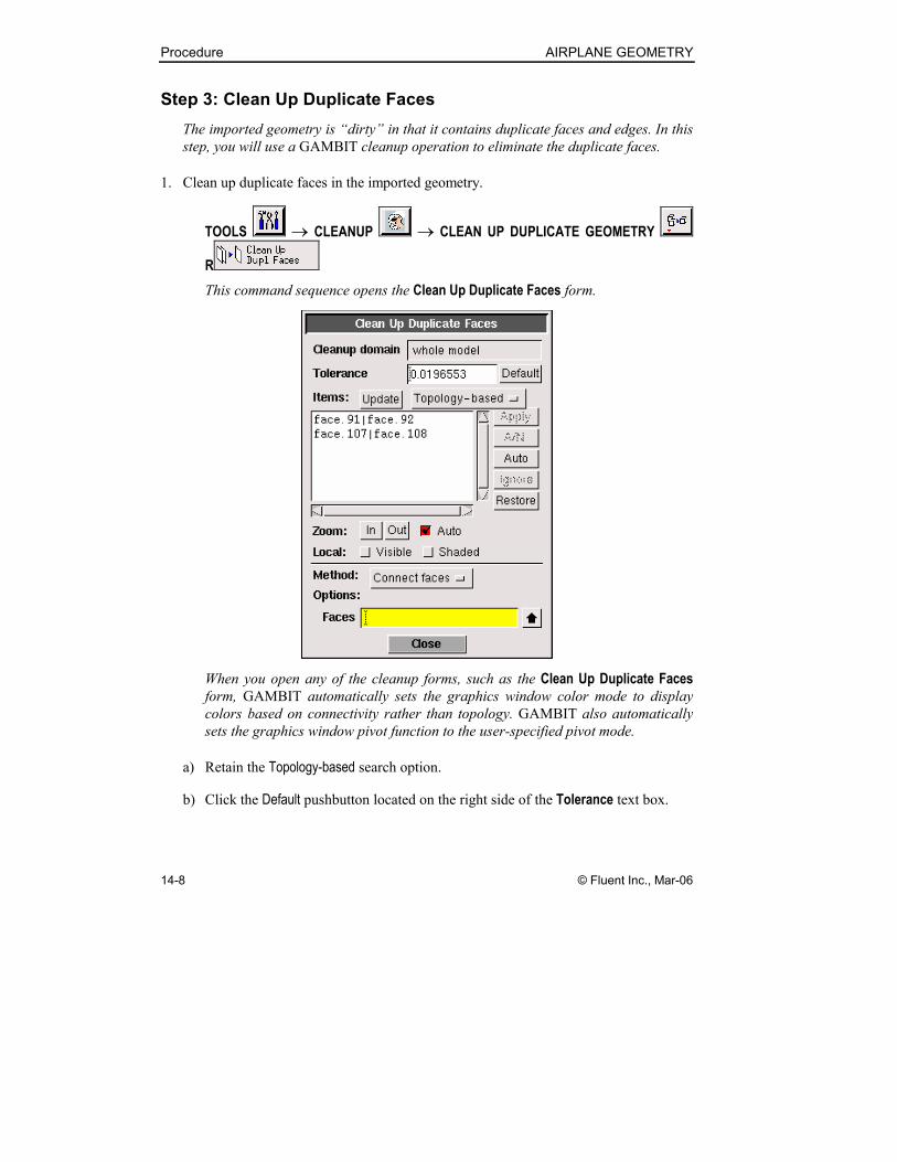
Step 3: Clean Up Duplicate Faces
The imported geometry is “dirty” in that it contains duplicate faces and edges. In this
step, you will use a GAMBIT cleanup operation to eliminate the duplicate faces.
1. Clean up duplicate faces in the imported geometry.
TOOLS → CLEANUP → CLEAN UP DUPLICATE GEOMETRY
R
This command sequence opens the Clean Up Duplicate Faces form.
When you open any of the cleanup forms, such as the Clean Up Duplicate Faces
form, GAMBIT automatically sets the graphics window color mode to display
colors based on connectivity rather than topology. GAMBIT also automatically
sets the graphics window pivot function to the user-specified pivot mode.
a) Retain the Topology-based search option.
b) Click the Default pushbutton located on the right side of the Tolerance text box.
AIRPLANE GEOMETRY Procedure
© Fluent Inc., Mar-06 14-9
When you click the Default pushbutton, GAMBIT displays the Tolerance
default value and populates the Items list with two sets of faces that meet the
tolerance criterion. For the Topology-based search option, the Items list
contains sets of faces that are topologically equivalent to each other and the
edges and surfaces of which are within Tolerance of each other.
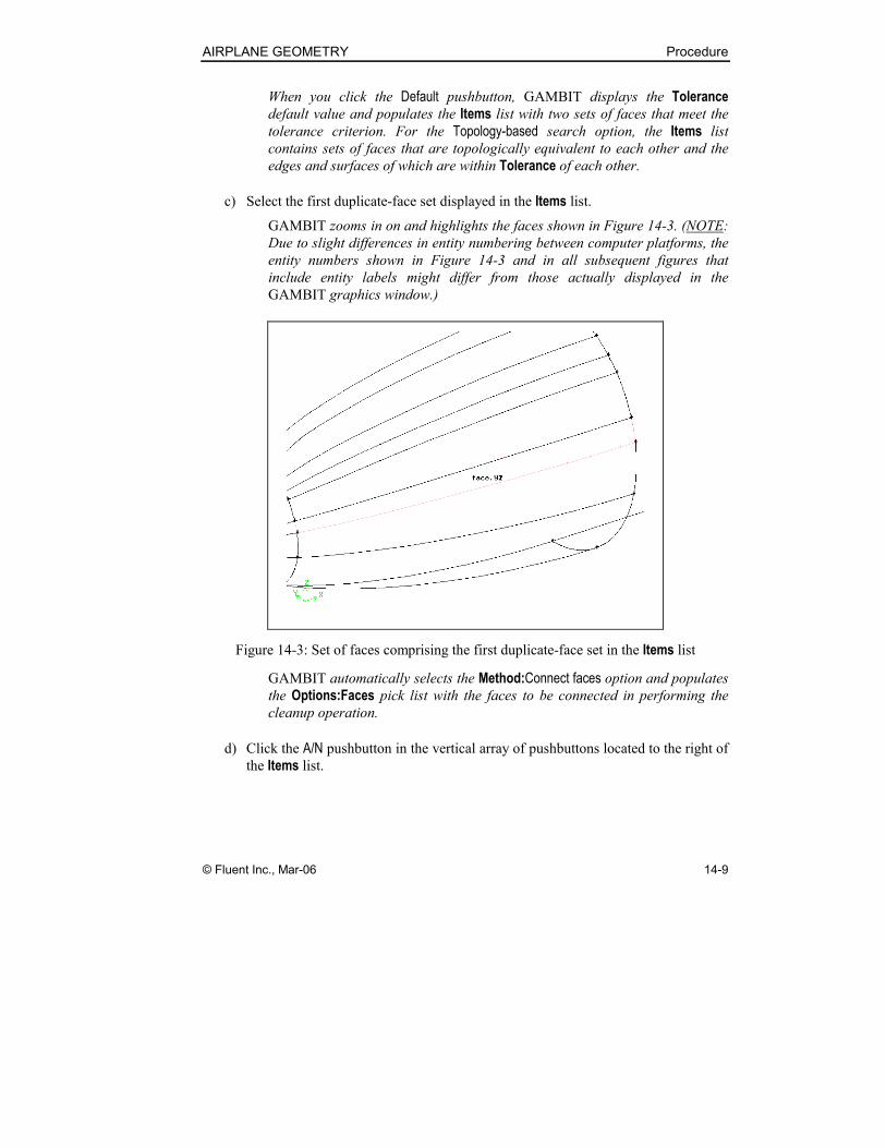
c) Select the first duplicate-face set displayed in the Items list.
GAMBIT zooms in on and highlights the faces shown in Figure 14-3. (NOTE:
Due to slight differences in entity numbering between computer platforms, the
entity numbers shown in Figure 14-3 and in all subsequent figures that
include entity labels might differ from those actually displayed in the
GAMBIT graphics window.)
Figure 14-3: Set of faces comprising the first duplicate-face set in the Items list
GAMBIT automatically selects the Method:Connect faces option and populates
the Options:Faces pick list with the faces to be connected in performing the
cleanup operation.
d) Click the A/N pushbutton in the vertical array of pushbuttons located to the right of
the Items list.
Procedure AIRPLANE GEOMETRY
14-10 © Fluent Inc., Mar-06
The A/N (“Apply/Next”) pushbutton applies the Connect faces method to clean
up the duplicate faces and automatically selects the remaining duplicate-face
set in the Items list.
e) Click Apply to clean up the remaining set of duplicate faces.
f) Click the FIT TO WINDOW command button at the top left of the Global
Control toolpad to see the full model geometry in the graphics window.
The removal of the duplicate faces does not significantly affect the appearance
of the airplane geometry.
AIRPLANE GEOMETRY Procedure
© Fluent Inc., Mar-06 14-11
Step 4: View List of Duplicate Edges
In addition to the duplicate faces cleaned up in the previous step, the imported
geometry contains many duplicate edges. In this step, you will use a GAMBIT
cleanup operation to view the list the duplicate edges.
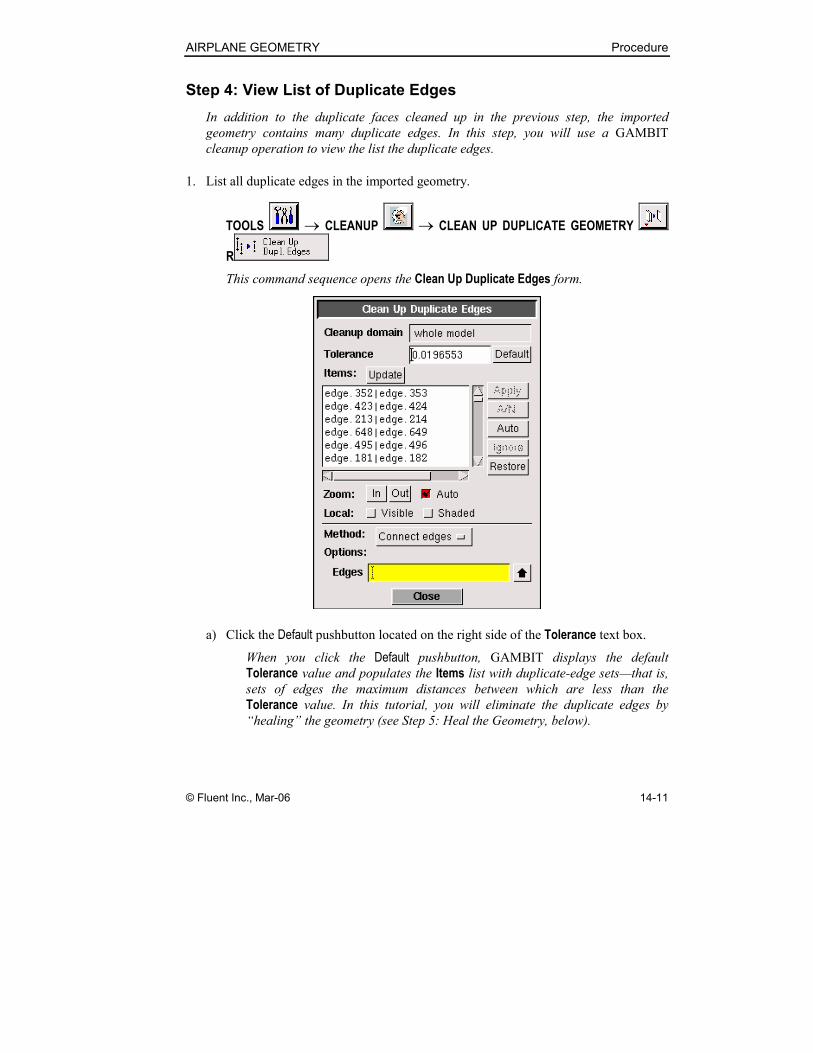
1. List all duplicate edges in the imported geometry.
TOOLS → CLEANUP → CLEAN UP DUPLICATE GEOMETRY
R
This command sequence opens the Clean Up Duplicate Edges form.
a) Click the Default pushbutton located on the right side of the Tolerance text box.
When you click the Default pushbutton, GAMBIT displays the default
Tolerance value and populates the Items list with duplicate-edge sets—that is,
sets of edges the maximum distances between which are less than the
Tolerance value. In this tutorial, you will eliminate the duplicate edges by
“healing” the geometry (see Step 5: Heal the Geometry, below).
Procedure AIRPLANE GEOMETRY
14-12 © Fluent Inc., Mar-06
Step 5: Heal the Geometry
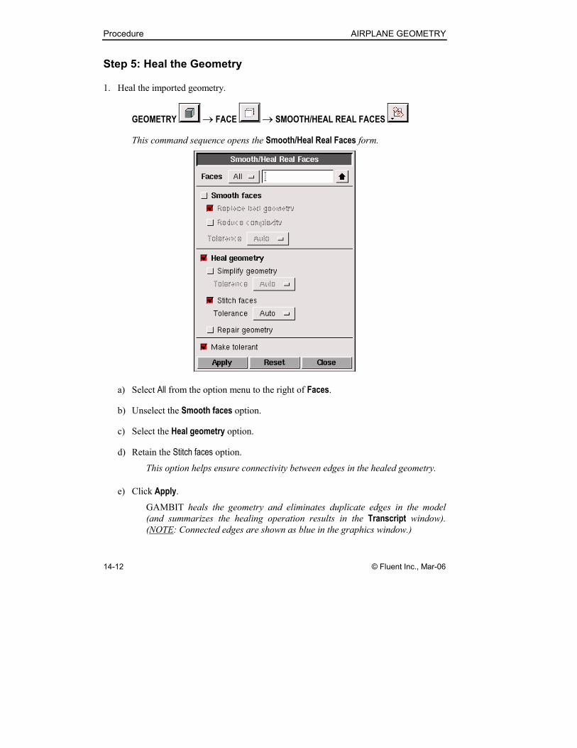
1. Heal the imported geometry.
GEOMETRY → FACE → SMOOTH/HEAL REAL FACES
This command sequence opens the Smooth/Heal Real Faces form.
a) Select All from the option menu to the right of Faces.
b) Unselect the Smooth faces option.
c) Select the Heal geometry option.
d) Retain the Stitch faces option.
This option helps ensure connectivity between edges in the healed geometry.
e) Click Apply.
GAMBIT heals the geometry and eliminates duplicate edges in the model
(and summarizes the healing operation results in the Transcript window).
(NOTE: Connected edges are shown as blue in the graphics window.)
AIRPLANE GEOMETRY Procedure
© Fluent Inc., Mar-06 14-13
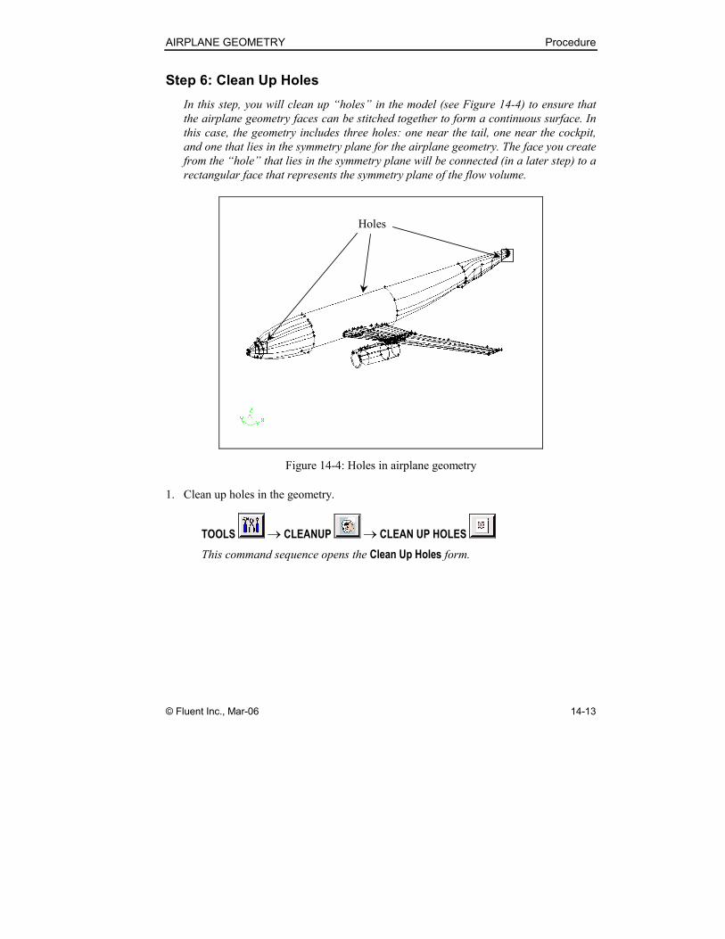
Step 6: Clean Up Holes
In this step, you will clean up “holes” in the model (see Figure 14-4) to ensure that
the airplane geometry faces can be stitched together to form a continuous surface. In
this case, the geometry includes three holes: one near the tail, one near the cockpit,
and one that lies in the symmetry plane for the airplane geometry. The face you create
from the “hole” that lies in the symmetry plane will be connected (in a later step) to a
rectangular face that represents the symmetry plane of the flow volume.
Holes
Figure 14-4: Holes in airplane geometry
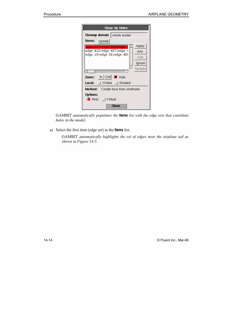
1. Clean up holes in the geometry.
TOOLS → CLEANUP → CLEAN UP HOLES
This command sequence opens the Clean Up Holes form.
Procedure AIRPLANE GEOMETRY
14-14 © Fluent Inc., Mar-06
GAMBIT automatically populates the Items list with the edge sets that constitute
holes in the model.
a) Select the first item (edge set) in the Items list.
GAMBIT automatically highlights the set of edges near the airplane tail as
shown in Figure 14-5.
AIRPLANE GEOMETRY Procedure
© Fluent Inc., Mar-06 14-15
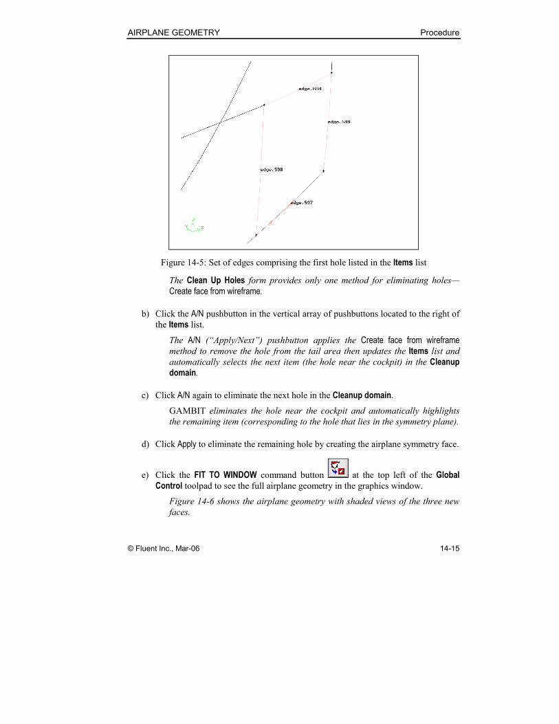
Figure 14-5: Set of edges comprising the first hole listed in the Items list
The Clean Up Holes form provides only one method for eliminating holes—
Create face from wireframe.
b) Click the A/N pushbutton in the vertical array of pushbuttons located to the right of
the Items list.
The A/N (“Apply/Next”) pushbutton applies the Create face from wireframe
method to remove the hole from the tail area then updates the Items list and
automatically selects the next item (the hole near the cockpit) in the Cleanup
domain.
c) Click A/N again to eliminate the next hole in the Cleanup domain.
GAMBIT eliminates the hole near the cockpit and automatically highlights
the remaining item (corresponding to the hole that lies in the symmetry plane).
d) Click Apply to eliminate the remaining hole by creating the airplane symmetry face.
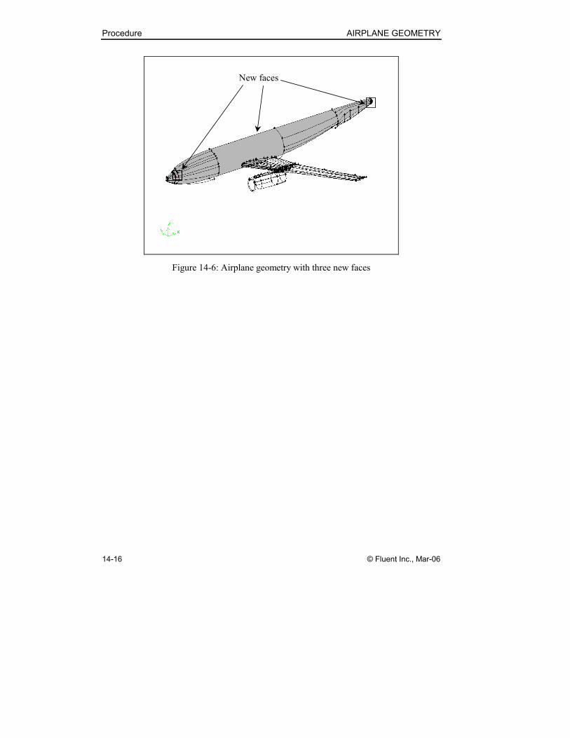
e) Click the FIT TO WINDOW command button at the top left of the Global
Control toolpad to see the full airplane geometry in the graphics window.
Figure 14-6 shows the airplane geometry with shaded views of the three new
faces.
Procedure AIRPLANE GEOMETRY
14-16 © Fluent Inc., Mar-06
New faces
Figure 14-6: Airplane geometry with three new faces
AIRPLANE GEOMETRY Procedure
© Fluent Inc., Mar-06 14-17
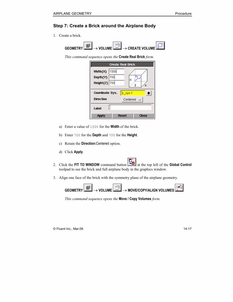
Step 7: Create a Brick around the Airplane Body
1. Create a brick.
GEOMETRY → VOLUME → CREATE VOLUME
This command sequence opens the Create Real Brick form.
a) Enter a value of 1500 for the Width of the brick.
b) Enter 700 for the Depth and 700 for the Height.
c) Retain the Direction:Centered option.
d) Click Apply.
2. Click the FIT TO WINDOW command button at the top left of the Global Control
toolpad to see the brick and full airplane body in the graphics window.
3. Align one face of the brick with the symmetry plane of the airplane geometry.
GEOMETRY → VOLUME → MOVE/COPY/ALIGN VOLUMES
This command sequence opens the Move / Copy Volumes form.

Procedure AIRPLANE GEOMETRY
14-18 © Fluent Inc., Mar-06
a) Select (Shift-left-click) the brick in the graphics window.
b) Retain Move (the default) under Volumes in the Move / Copy Volumes form.
c) Retain the Operation:Translate option.
d) Enter (250, -350, 0) under Global to move the brick 250 units in the x direction
and -350 units in the y direction.
Note that GAMBIT automatically fills in the values under Local as you enter
values under Global.
e) Click Apply.
4. Click the FIT TO WINDOW command button at the top left of the Global Control
toolpad to see the full brick and airplane body in the graphics window.
AIRPLANE GEOMETRY Procedure
© Fluent Inc., Mar-06 14-19
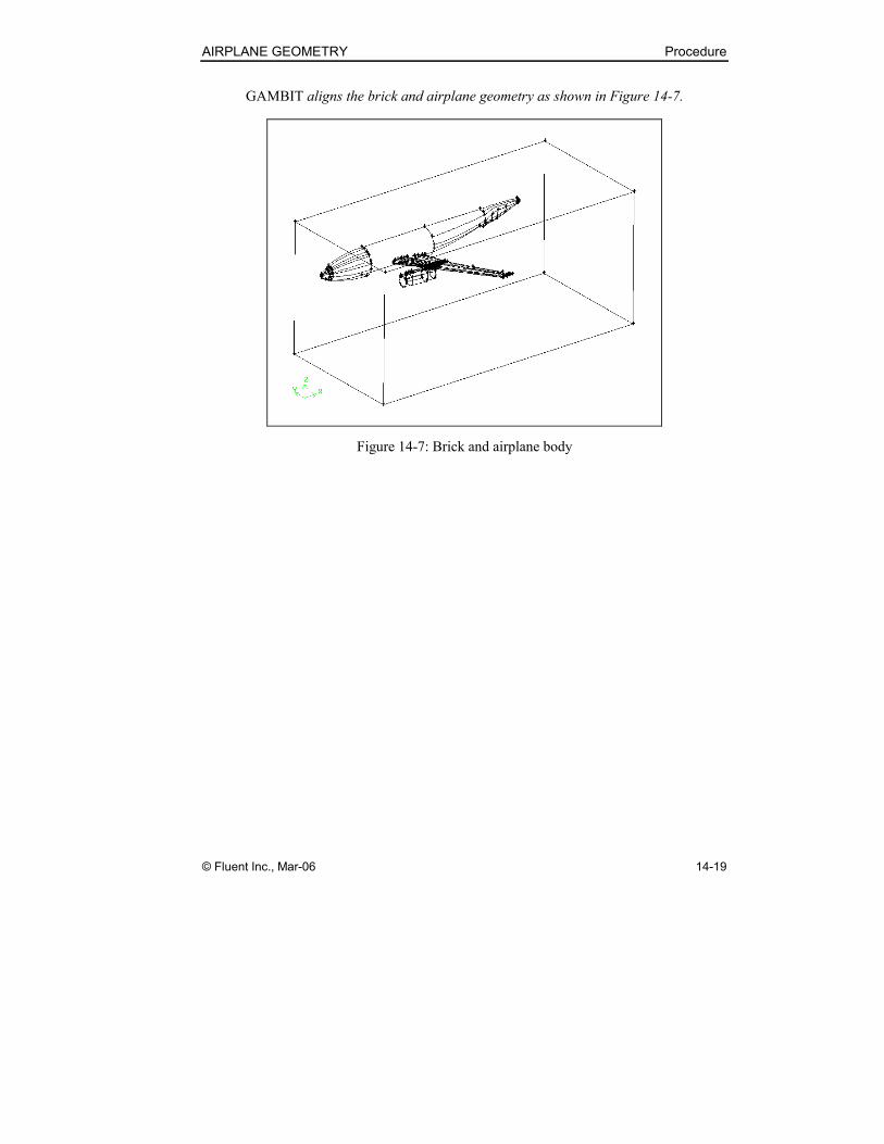
GAMBIT aligns the brick and airplane geometry as shown in Figure 14-7.
Figure 14-7: Brick and airplane body
Procedure AIRPLANE GEOMETRY
14-20 © Fluent Inc., Mar-06
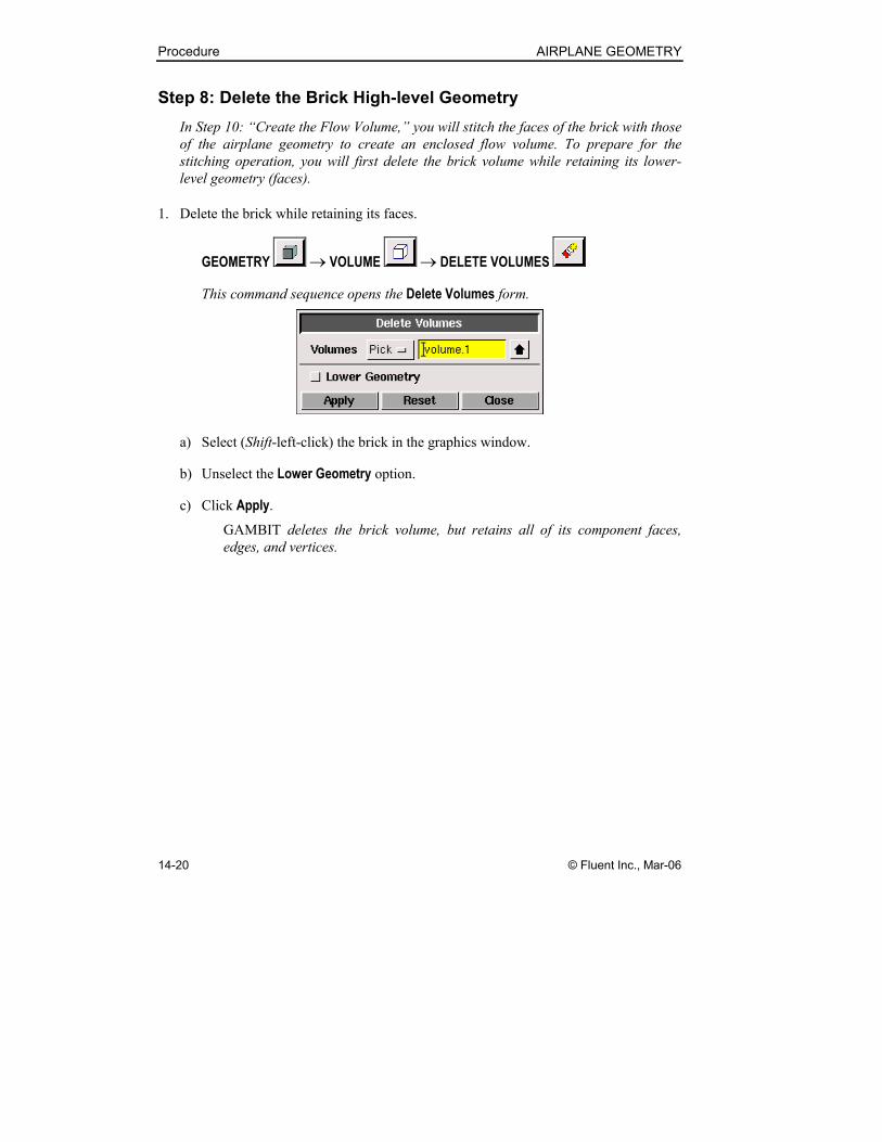
Step 8: Delete the Brick High-level Geometry
In Step 10: “Create the Flow Volume,” you will stitch the faces of the brick with those
of the airplane geometry to create an enclosed flow volume. To prepare for the
stitching operation, you will first delete the brick volume while retaining its lower-
level geometry (faces).
1. Delete the brick while retaining its faces.
GEOMETRY → VOLUME → DELETE VOLUMES
This command sequence opens the Delete Volumes form.
a) Select (Shift-left-click) the brick in the graphics window.
b) Unselect the Lower Geometry option.
c) Click Apply.
GAMBIT deletes the brick volume, but retains all of its component faces,
edges, and vertices.
AIRPLANE GEOMETRY Procedure
© Fluent Inc., Mar-06 14-21
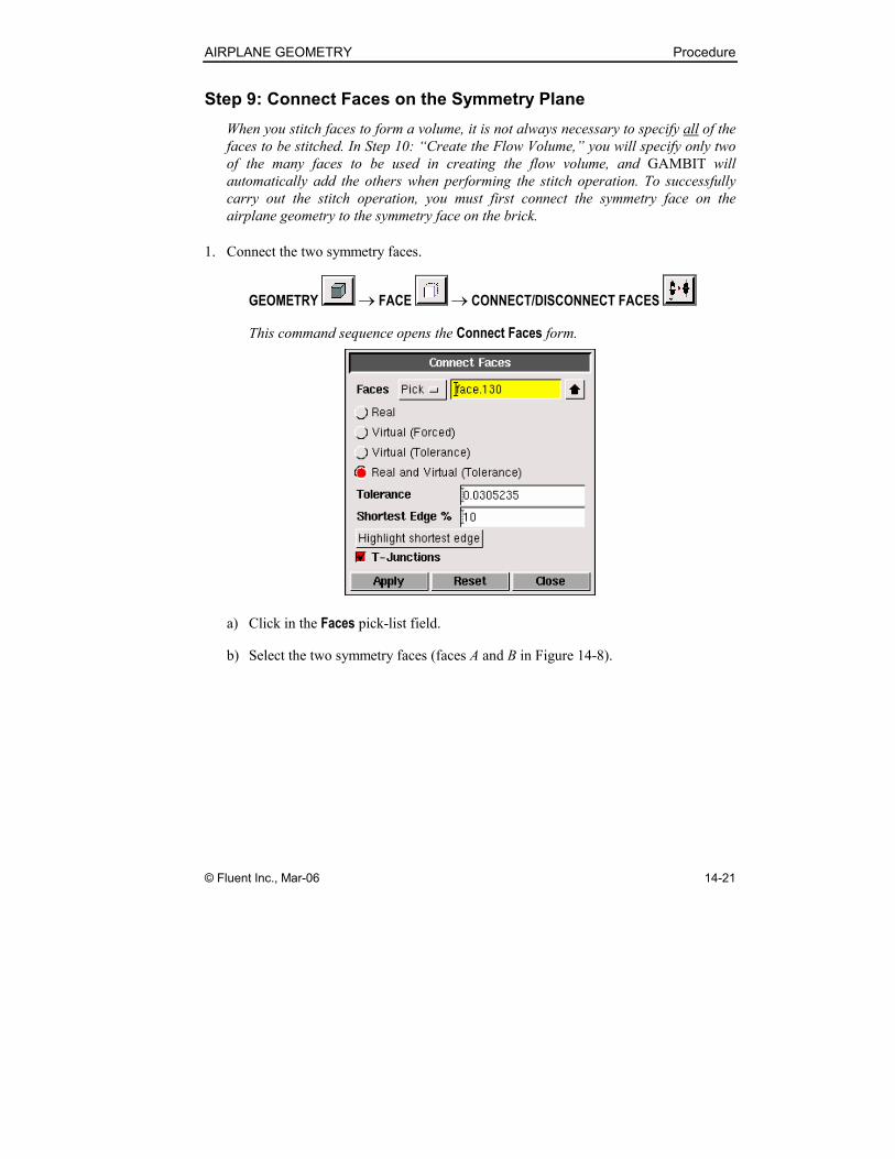
Step 9: Connect Faces on the Symmetry Plane
When you stitch faces to form a volume, it is not always necessary to specify all of the
faces to be stitched. In Step 10: “Create the Flow Volume,” you will specify only two
of the many faces to be used in creating the flow volume, and GAMBIT will
automatically add the others when performing the stitch operation. To successfully
carry out the stitch operation, you must first connect the symmetry face on the
airplane geometry to the symmetry face on the brick.
1. Connect the two symmetry faces.
GEOMETRY → FACE → CONNECT/DISCONNECT FACES
This command sequence opens the Connect Faces form.
a) Click in the Faces pick-list field.
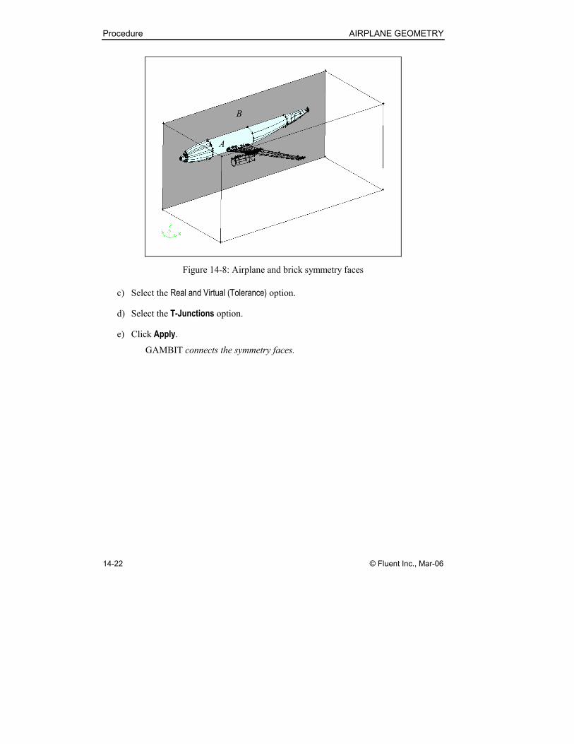
b) Select the two symmetry faces (faces A and B in Figure 14-8).
Procedure AIRPLANE GEOMETRY
14-22 © Fluent Inc., Mar-06
A
B
Figure 14-8: Airplane and brick symmetry faces
c) Select the Real and Virtual (Tolerance) option.
d) Select the T-Junctions option.
e) Click Apply.
GAMBIT connects the symmetry faces.

AIRPLANE GEOMETRY Procedure
© Fluent Inc., Mar-06 14-23
Step 10: Create the Flow Volume
Now that you have connected the symmetry faces, you can create the flow volume by
specifying just one of the many faces that will be used to enclose the volume.
1. Stitch the faces to form the flow volume.
GEOMETRY → VOLUME → STITCH FACES
This command sequence opens the Stitch Faces form.
a) Click in the Faces pick-list field.
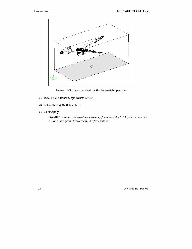
b) Select one face of the flow volume—for example, the bottom face (C) shown in
Figure 14-9.
Procedure AIRPLANE GEOMETRY
14-24 © Fluent Inc., Mar-06
C
Figure 14-9: Face specified for the face-stitch operation
c) Retain the Number:Single volume option.
d) Select the Type:Virtual option.
e) Click Apply.
GAMBIT stitches the airplane geometry faces and the brick faces external to
the airplane geometry to create the flow volume.
AIRPLANE GEOMETRY Procedure
© Fluent Inc., Mar-06 14-25
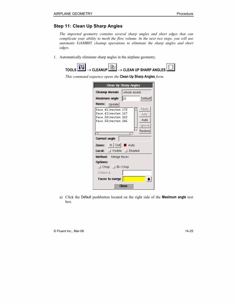
Step 11: Clean Up Sharp Angles
The imported geometry contains several sharp angles and short edges that can
complicate your ability to mesh the flow volume. In the next two steps, you will use
automatic GAMBIT cleanup operations to eliminate the sharp angles and short
edges.
1. Automatically eliminate sharp angles in the airplane geometry.
TOOLS → CLEANUP → CLEAN UP SHARP ANGLES
This command sequence opens the Clean Up Sharp Angles form.
a) Click the Default pushbutton located on the right side of the Maximum angle text
box.
Procedure AIRPLANE GEOMETRY
14-26 © Fluent Inc., Mar-06
When you click the Default pushbutton, GAMBIT displays the Maximum angle
default value (20) and populates the Items list with four face-vertex pairs that
meet the maximum-angle criterion. In this case, you will use an automatic
operation to eliminate all three of the sharp angles.
b) Click Auto in the vertical array of pushbuttons located to the right of the Items list.
GAMBIT uses face-merge operations to automatically remove all of the sharp
angles from the model. (NOTE: In general practice, you should exercise
caution when using the Auto pushbutton to execute cleanup operations. Less-
experienced GAMBIT users should select items one at a time in the Items list
and use the Apply and/or A/N pushbuttons, instead.)
c) Click the FIT TO WINDOW command button at the top left of the Global
Control toolpad to see the full flow-volume geometry in the graphics window.
AIRPLANE GEOMETRY Procedure
© Fluent Inc., Mar-06 14-27
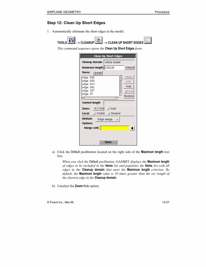
Step 12: Clean Up Short Edges
1. Automatically eliminate the short edges in the model.
TOOLS → CLEANUP → CLEAN UP SHORT EDGES
This command sequence opens the Clean Up Short Edges form.
a) Click the Default pushbutton located on the right side of the Maximum length text
box.
When you click the Default pushbutton, GAMBIT displays the Maximum length
of edges to be included in the Items list and populates the Items list with all
edges in the Cleanup domain that meet the Maximum length criterion. By
default, the Maximum length value is 10 times greater than the arc length of
the shortest edge in the Cleanup domain.
b) Unselect the Zoom:Auto option.
Procedure AIRPLANE GEOMETRY
14-28 © Fluent Inc., Mar-06
By default, GAMBIT automatically zooms in on any item currently selected
for a cleanup operation and displays the labels of the entities involved in the
operation. If you retain the Zoom:Auto option in this case, GAMBIT will zoom
in on every edge as it is removed from the model, thereby making it difficult to
follow the cleanup operation in the graphics window.
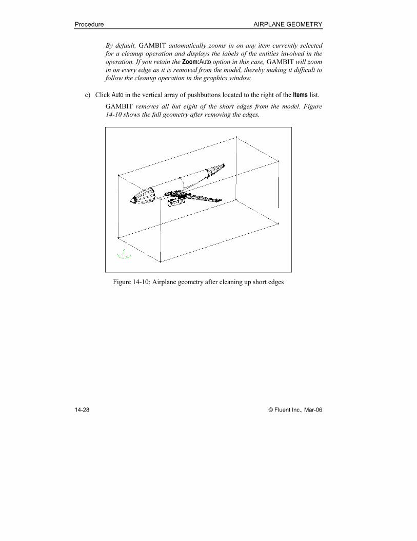
c) Click Auto in the vertical array of pushbuttons located to the right of the Items list.
GAMBIT removes all but eight of the short edges from the model. Figure
14-10 shows the full geometry after removing the edges.
Figure 14-10: Airplane geometry after cleaning up short edges
AIRPLANE GEOMETRY Procedure
© Fluent Inc., Mar-06 14-29
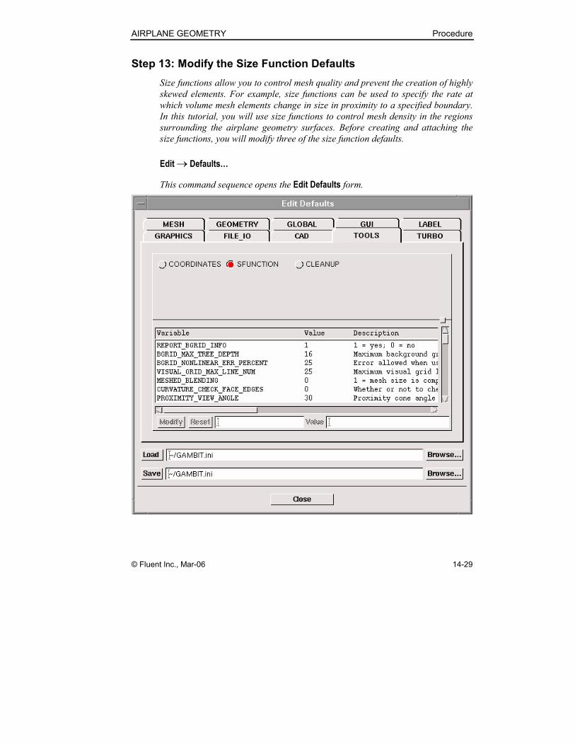
Step 13: Modify the Size Function Defaults
Size functions allow you to control mesh quality and prevent the creation of highly
skewed elements. For example, size functions can be used to specify the rate at
which volume mesh elements change in size in proximity to a specified boundary.
In this tutorial, you will use size functions to control mesh density in the regions
surrounding the airplane geometry surfaces. Before creating and attaching the
size functions, you will modify three of the size function defaults.
Edit → Defaults…
This command sequence opens the Edit Defaults form.

Procedure AIRPLANE GEOMETRY
14-30 © Fluent Inc., Mar-06
1. Select the TOOLS tab at the top of the form.
GAMBIT displays the available default settings for three “tools” operations—
coordinate system, size-function, and cleanup.
2. Select the SFUNCTION radio button.
GAMBIT displays the size-function defaults variables.
3. Use the Modify pushbutton on the Edit Defaults form to modify three size-function
defaults.
a) Set the CURVATURE_CHECK_FACE_EDGES default variable to 1.
b) Set the BGRID_MAX_TREE_DEPTH default variable to 20.
c) Set the BGRID_NONLINEAR_ERR_PERCENT default variable to 15.
The BGRID_MAX_TREE_DEPTH and BGRID_NONLINEAR_ERR_PERCENT
values specified here represent moderate, intermediate values. For informa-
tion concerning the use of such variables to control mesh quality, see “Create
Size Function” in Section 5.2.2 of the GAMBIT Modeling Guide .
4. Click Close to close the Edit Defaults form.
AIRPLANE GEOMETRY Procedure
© Fluent Inc., Mar-06 14-31
Step 14: Apply Size Functions to Control Mesh Quality
In this step, you will create and attach two types of size functions to control mesh
sizes in the regions adjacent to the airplane geometry surfaces. You will apply the size
functions to all faces associated with the external airplane surfaces (that is, all but the
airplane symmetry face). Before creating the size functions, however, you will modify
the graphics display to facilitate picking the size-function source and attachment
entities.
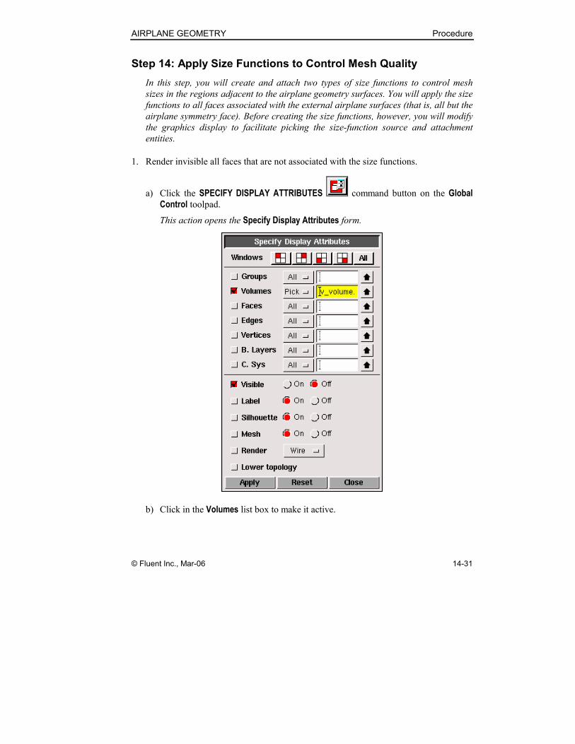
1. Render invisible all faces that are not associated with the size functions.
a) Click the SPECIFY DISPLAY ATTRIBUTES command button on the Global
Control toolpad.
This action opens the Specify Display Attributes form.
b) Click in the Volumes list box to make it active.
Procedure AIRPLANE GEOMETRY
14-32 © Fluent Inc., Mar-06
GAMBIT automatically activates the Volumes check box, indicating that the
display specifications are to apply to any specified volumes.
c) Select the volume in the graphics window.
d) Select the Visible:Off option.
e) Unselect the Lower topology option.
f) Click Apply.
GAMBIT turns off the display of the volume but retains the display of its
bounding faces. Now, you will turn off display of all faces other than the
symmetry plane and the airplane body.
g) Click in the Faces list box to make it active.
GAMBIT automatically activates the Faces check box, indicating that the
display specifications are to apply to any specified faces.
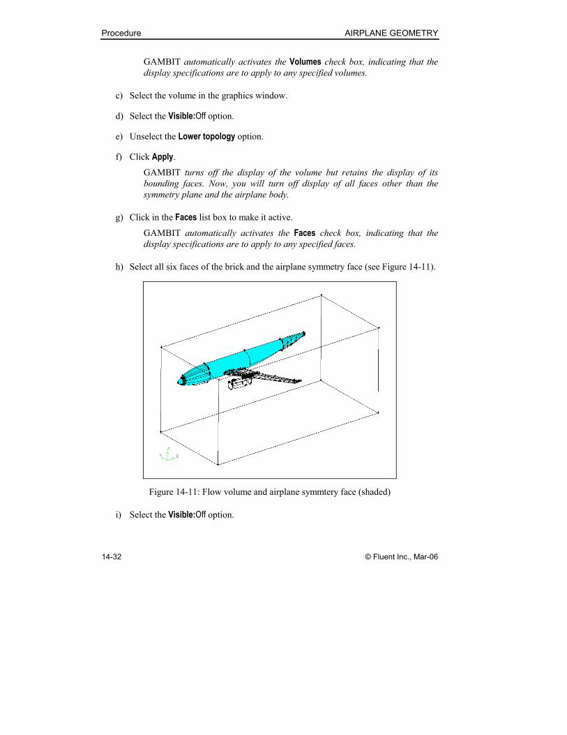
h) Select all six faces of the brick and the airplane symmetry face (see Figure 14-11).
Figure 14-11: Flow volume and airplane symmtery face (shaded)
i) Select the Visible:Off option.

AIRPLANE GEOMETRY Procedure
© Fluent Inc., Mar-06 14-33
j) Retain the Lower topology option.
k) Click Apply.
GAMBIT turns off the display of all faces that are not associated with the
airplane surface geometry (see Figure 14-12).
Figure 14-12: Graphics display after change in display attributes
l) On the Specify Display Attributes form, click Close to close the form.
2. Create and apply a fixed size function to the airplane geometry.
a) Open the Create Size Function form.
TOOLS → SIZE FUNCTIONS → CREATE SIZE FUNCTION
This command sequence opens the Create Size Function form.
Procedure AIRPLANE GEOMETRY
14-34 © Fluent Inc., Mar-06
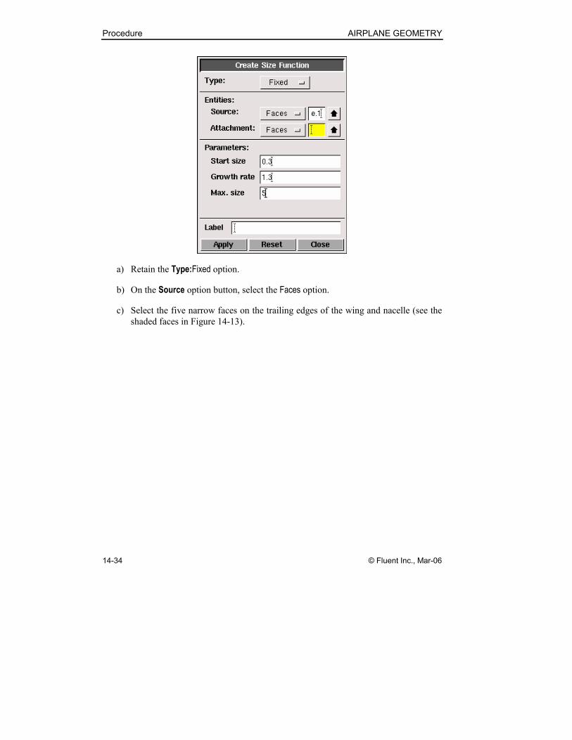
a) Retain the Type:Fixed option.
b) On the Source option button, select the Faces option.
c) Select the five narrow faces on the trailing edges of the wing and nacelle (see the
shaded faces in Figure 14-13).
AIRPLANE GEOMETRY Procedure
© Fluent Inc., Mar-06 14-35
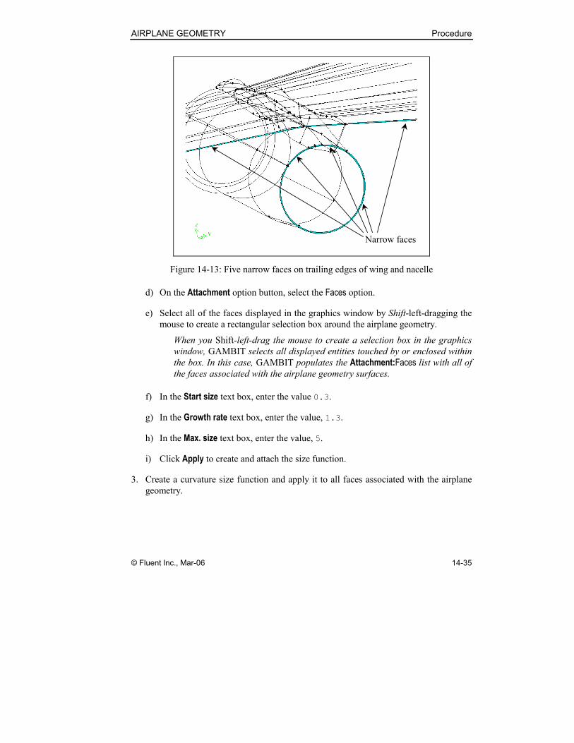
Narrow faces
Figure 14-13: Five narrow faces on trailing edges of wing and nacelle
d) On the Attachment option button, select the Faces option.
e) Select all of the faces displayed in the graphics window by Shift-left-dragging the
mouse to create a rectangular selection box around the airplane geometry.
When you Shift-left-drag the mouse to create a selection box in the graphics
window, GAMBIT selects all displayed entities touched by or enclosed within
the box. In this case, GAMBIT populates the Attachment:Faces list with all of
the faces associated with the airplane geometry surfaces.
f) In the Start size text box, enter the value 0.3.
g) In the Growth rate text box, enter the value, 1.3.
h) In the Max. size text box, enter the value, 5.
i) Click Apply to create and attach the size function.
3. Create a curvature size function and apply it to all faces associated with the airplane
geometry.
Procedure AIRPLANE GEOMETRY
14-36 © Fluent Inc., Mar-06
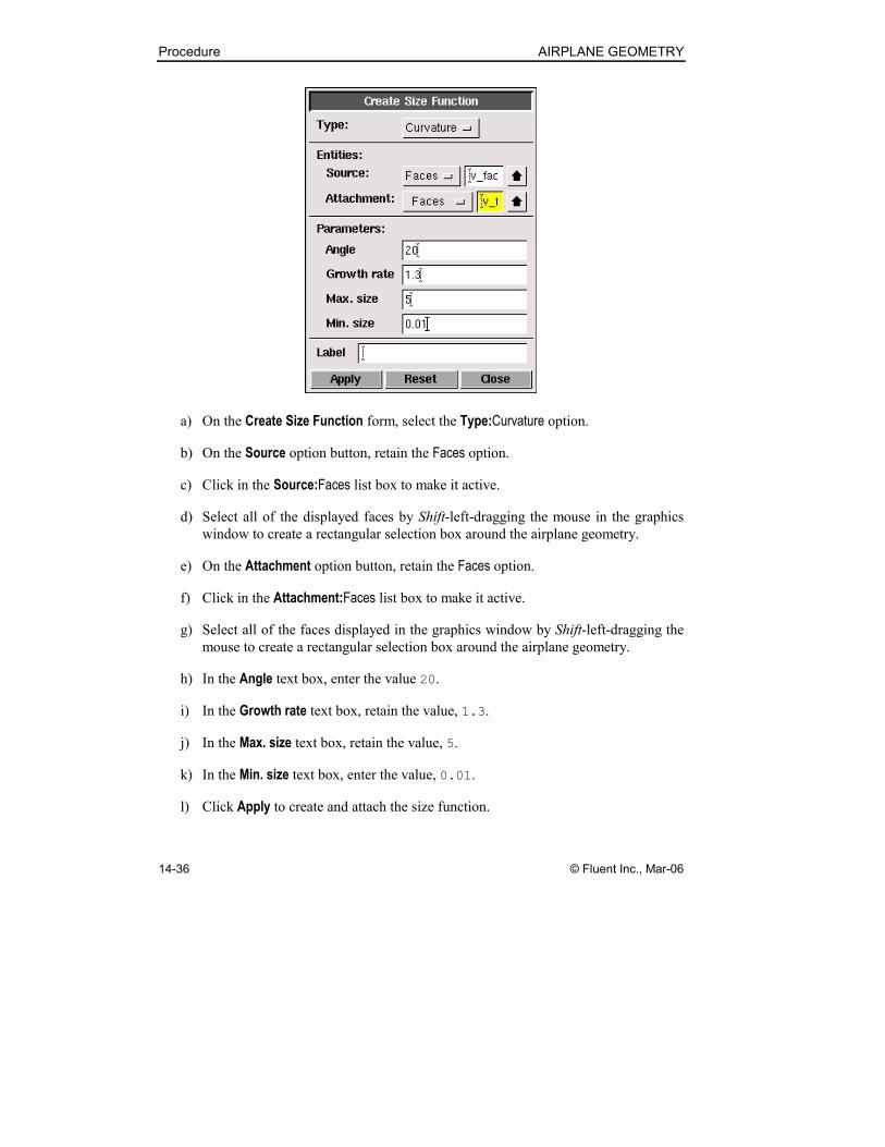
a) On the Create Size Function form, select the Type:Curvature option.
b) On the Source option button, retain the Faces option.
c) Click in the Source:Faces list box to make it active.
d) Select all of the displayed faces by Shift-left-dragging the mouse in the graphics
window to create a rectangular selection box around the airplane geometry.
e) On the Attachment option button, retain the Faces option.
f) Click in the Attachment:Faces list box to make it active.
g) Select all of the faces displayed in the graphics window by Shift-left-dragging the
mouse to create a rectangular selection box around the airplane geometry.
h) In the Angle text box, enter the value 20.
i) In the Growth rate text box, retain the value, 1.3.
j) In the Max. size text box, retain the value, 5.
k) In the Min. size text box, enter the value, 0.01.
l) Click Apply to create and attach the size function.
AIRPLANE GEOMETRY Procedure
© Fluent Inc., Mar-06 14-37
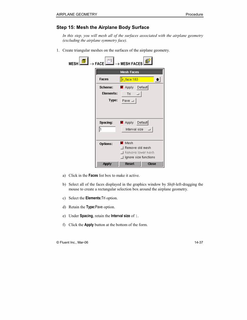
Step 15: Mesh the Airplane Body Surface
In this step, you will mesh all of the surfaces associated with the airplane geometry
(excluding the airplane symmetry face).
1. Create triangular meshes on the surfaces of the airplane geometry.
MESH → FACE → MESH FACES
a) Click in the Faces list box to make it active.
b) Select all of the faces displayed in the graphics window by Shift-left-dragging the
mouse to create a rectangular selection box around the airplane geometry.
c) Select the Elements:Tri option.
d) Retain the Type:Pave option.
e) Under Spacing, retain the Interval size of 1.
f) Click the Apply button at the bottom of the form.
Procedure AIRPLANE GEOMETRY
14-38 © Fluent Inc., Mar-06
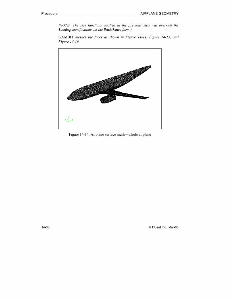
(NOTE: The size functions applied in the previous step will override the
Spacing specifications on the Mesh Faces form.)
GAMBIT meshes the faces as shown in Figure 14-14, Figure 14-15, and
Figure 14-16.
Figure 14-14: Airplane surface mesh—whole airplane
AIRPLANE GEOMETRY Procedure
© Fluent Inc., Mar-06 14-39
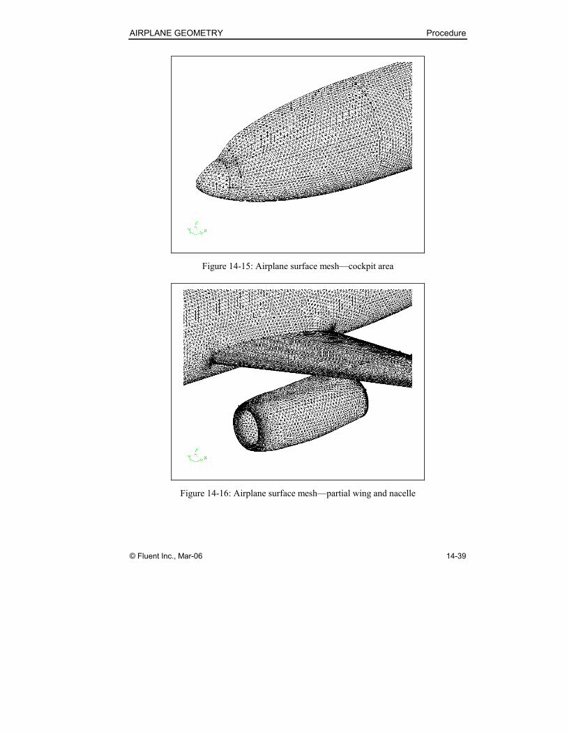
Figure 14-15: Airplane surface mesh—cockpit area
Figure 14-16: Airplane surface mesh—partial wing and nacelle
Procedure AIRPLANE GEOMETRY
14-40 © Fluent Inc., Mar-06
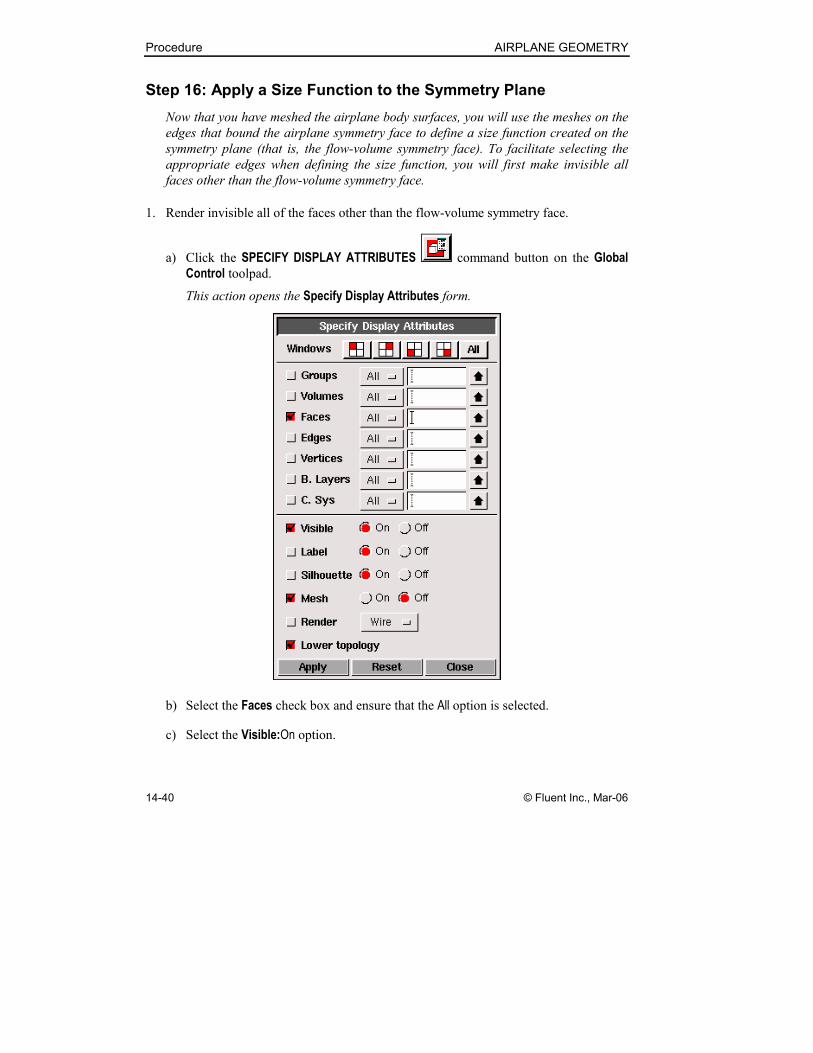
Step 16: Apply a Size Function to the Symmetry Plane
Now that you have meshed the airplane body surfaces, you will use the meshes on the
edges that bound the airplane symmetry face to define a size function created on the
symmetry plane (that is, the flow-volume symmetry face). To facilitate selecting the
appropriate edges when defining the size function, you will first make invisible all
faces other than the flow-volume symmetry face.
1. Render invisible all of the faces other than the flow-volume symmetry face.
a) Click the SPECIFY DISPLAY ATTRIBUTES command button on the Global
Control toolpad.
This action opens the Specify Display Attributes form.
b) Select the Faces check box and ensure that the All option is selected.
c) Select the Visible:On option.
AIRPLANE GEOMETRY Procedure
© Fluent Inc., Mar-06 14-41
d) Select the Mesh:Off option.
e) Click Apply.
GAMBIT renders the geometry visible and the mesh invisible.
f) Click the FIT TO WINDOW command button at the top left of the Global
Control toolpad to see the full model geometry in the graphics window.
g) Click the Faces list box to make it active.
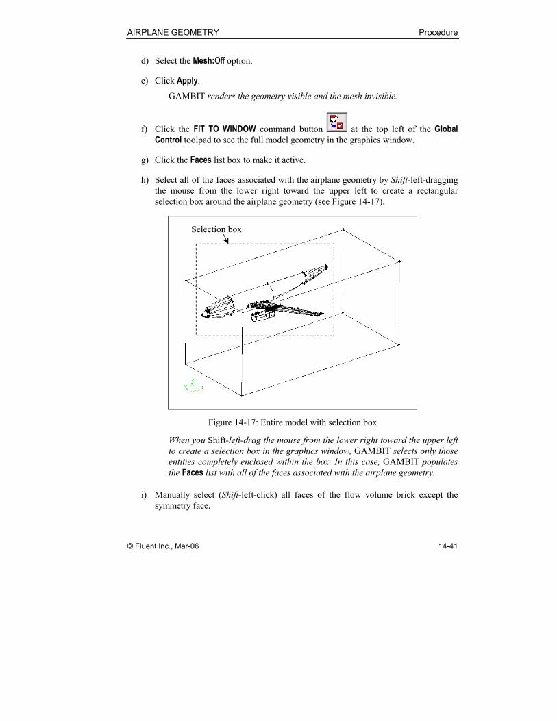
h) Select all of the faces associated with the airplane geometry by Shift-left-dragging
the mouse from the lower right toward the upper left to create a rectangular
selection box around the airplane geometry (see Figure 14-17).
Selection box
Figure 14-17: Entire model with selection box
When you Shift-left-drag the mouse from the lower right toward the upper left
to create a selection box in the graphics window, GAMBIT selects only those
entities completely enclosed within the box. In this case, GAMBIT populates
the Faces list with all of the faces associated with the airplane geometry.
i) Manually select (Shift-left-click) all faces of the flow volume brick except the
symmetry face.
Procedure AIRPLANE GEOMETRY
14-42 © Fluent Inc., Mar-06
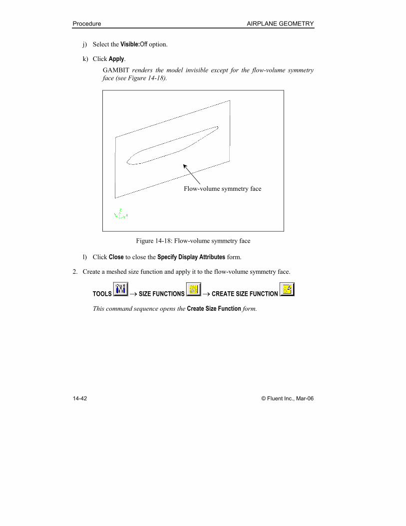
j) Select the Visible:Off option.
k) Click Apply.
GAMBIT renders the model invisible except for the flow-volume symmetry
face (see Figure 14-18).
Flow-volume symmetry face
Figure 14-18: Flow-volume symmetry face
l) Click Close to close the Specify Display Attributes form.
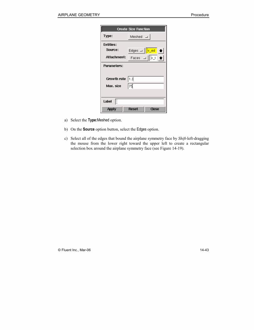
2. Create a meshed size function and apply it to the flow-volume symmetry face.
TOOLS → SIZE FUNCTIONS → CREATE SIZE FUNCTION
This command sequence opens the Create Size Function form.
AIRPLANE GEOMETRY Procedure
© Fluent Inc., Mar-06 14-43
a) Select the Type:Meshed option.
b) On the Source option button, select the Edges option.
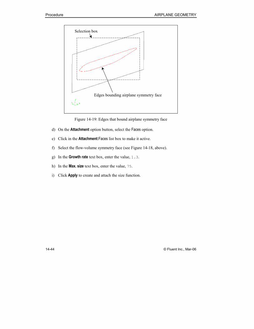
c) Select all of the edges that bound the airplane symmetry face by Shift-left-dragging
the mouse from the lower right toward the upper left to create a rectangular
selection box around the airplane symmetry face (see Figure 14-19).
Procedure AIRPLANE GEOMETRY
14-44 © Fluent Inc., Mar-06
Selection box
Edges bounding airplane symmetry face
Figure 14-19: Edges that bound airplane symmetry face
d) On the Attachment option button, select the Faces option.
e) Click in the Attachment:Faces list box to make it active.
f) Select the flow-volume symmetry face (see Figure 14-18, above).
g) In the Growth rate text box, enter the value, 1.3.
h) In the Max. size text box, enter the value, 75.
i) Click Apply to create and attach the size function.
AIRPLANE GEOMETRY Procedure
© Fluent Inc., Mar-06 14-45
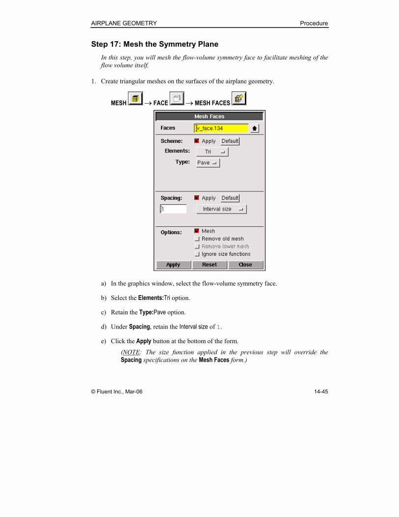
Step 17: Mesh the Symmetry Plane
In this step, you will mesh the flow-volume symmetry face to facilitate meshing of the
flow volume itself.
1. Create triangular meshes on the surfaces of the airplane geometry.
MESH → FACE → MESH FACES
a) In the graphics window, select the flow-volume symmetry face.
b) Select the Elements:Tri option.
c) Retain the Type:Pave option.
d) Under Spacing, retain the Interval size of 1.
e) Click the Apply button at the bottom of the form.
(NOTE: The size function applied in the previous step will override the
Spacing specifications on the Mesh Faces form.)
Procedure AIRPLANE GEOMETRY
14-46 © Fluent Inc., Mar-06
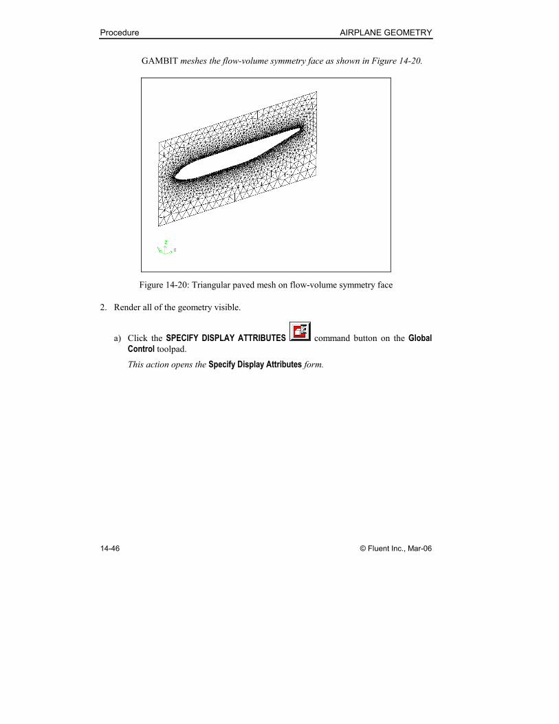
GAMBIT meshes the flow-volume symmetry face as shown in Figure 14-20.
Figure 14-20: Triangular paved mesh on flow-volume symmetry face
2. Render all of the geometry visible.
a) Click the SPECIFY DISPLAY ATTRIBUTES command button on the Global
Control toolpad.
This action opens the Specify Display Attributes form.
AIRPLANE GEOMETRY Procedure
© Fluent Inc., Mar-06 14-47
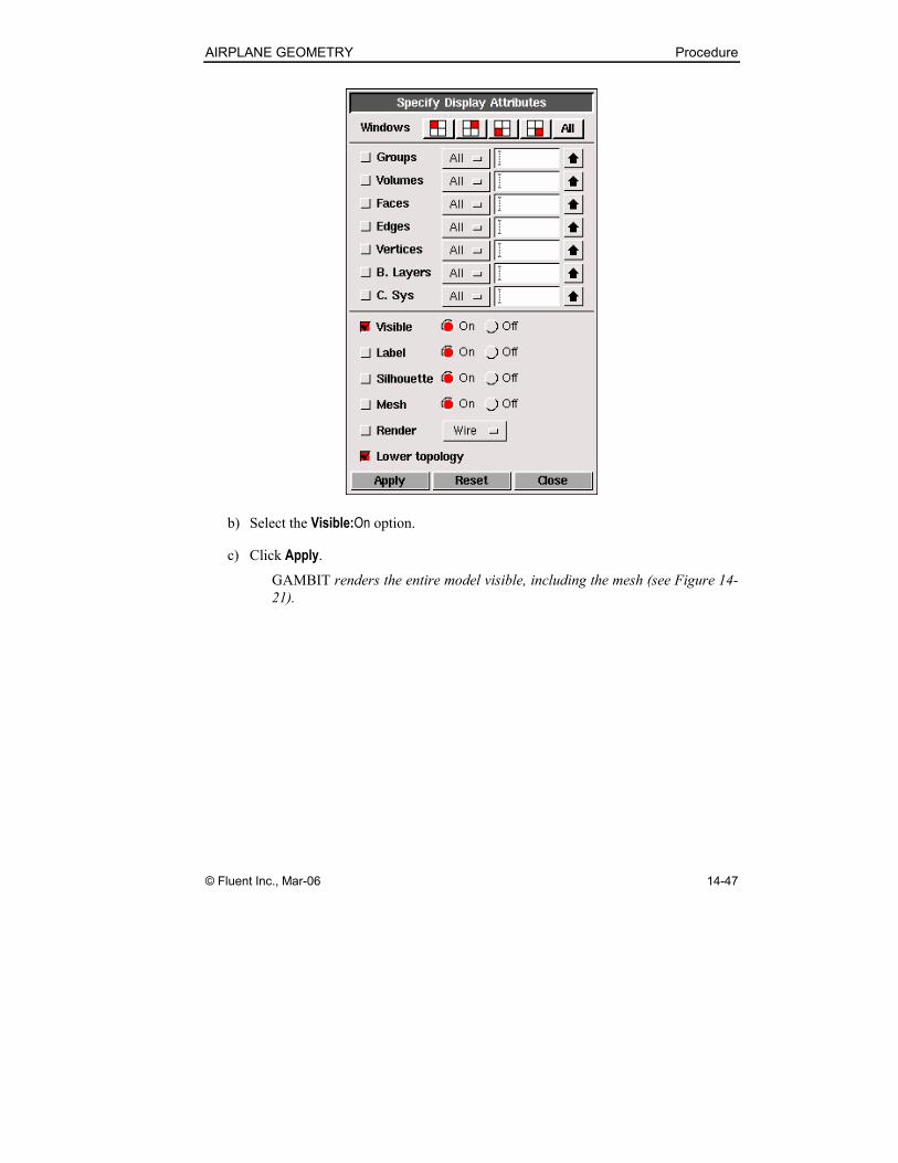
b) Select the Visible:On option.
c) Click Apply.
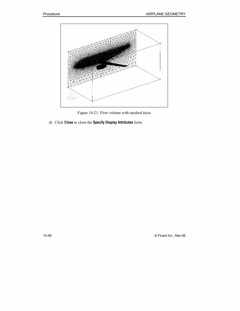
GAMBIT renders the entire model visible, including the mesh (see Figure 14-
21).
Procedure AIRPLANE GEOMETRY
14-48 © Fluent Inc., Mar-06
Figure 14-21: Flow volume with meshed faces
d) Click Close to close the Specify Display Attributes form.
AIRPLANE GEOMETRY Procedure
© Fluent Inc., Mar-06 14-49
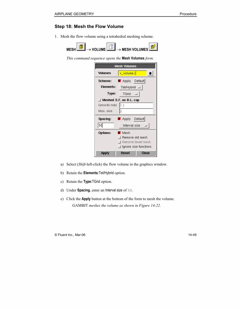
Step 18: Mesh the Flow Volume
1. Mesh the flow volume using a tetrahedral meshing scheme.
MESH → VOLUME → MESH VOLUMES
This command sequence opens the Mesh Volumes form.
a) Select (Shift-left-click) the flow volume in the graphics window.
b) Retain the Elements:Tet/Hybrid option.
c) Retain the Type:TGrid option.
d) Under Spacing, enter an Interval size of 50.
e) Click the Apply button at the bottom of the form to mesh the volume.
GAMBIT meshes the volume as shown in Figure 14-22.

Procedure AIRPLANE GEOMETRY
14-50 © Fluent Inc., Mar-06
Figure 14-22: Meshed airplane flow volume
As an alternative to the procedure described in Steps 16, 17, and 18, above, you
could attach a mesh size function to the flow volume, using the meshed airplane
body surfaces as sources for the size function, and mesh the flow volume directly.
Such a procedure would produce a smoother distribution of mesh elements within
the volume but would significantly increase the meshing time and number of
elements created.
AIRPLANE GEOMETRY Procedure
© Fluent Inc., Mar-06 14-51
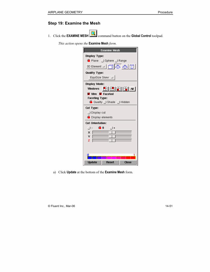
Step 19: Examine the Mesh
1. Click the EXAMINE MESH command button on the Global Control toolpad.
This action opens the Examine Mesh form.
a) Click Update at the bottom of the Examine Mesh form.
Procedure AIRPLANE GEOMETRY
14-52 © Fluent Inc., Mar-06
GAMBIT does not automatically update the graphics display when you open
the Examine Mesh form or modify its specifications, such as Display Type or
Quality Type. To update the graphics display, you must click the Update
pushbutton located at the bottom of the form. GAMBIT displays the Update
pushbutton label in red lettering whenever the display needs to be updated to
reflect the current Examine Mesh specifications.
Some Examine Mesh operations automatically update the graphics display.
For example, if you select the Display Type:Range option and click one of the
histogram bars, GAMBIT automatically updates the display.
b) Retain the Display Type:Plane option at the top of the form.
The Examine Mesh form allows you to view mesh characteristics for various types
of 3-D mesh elements. In this case, the volume mesh consists entirely of
tetrahedral elements; therefore, you must specify the viewing of such elements.
c) Retain the 3-D Element option, and click the tetrahedral button at the top of
the form.
By default, GAMBIT enables the brick button , thereby enabling the viewing
of hexahedral elements. In this case, you can retain or disable (by clicking) the
brick element button without affecting the mesh display—because the volume
mesh does not contain any hexahedral elements.
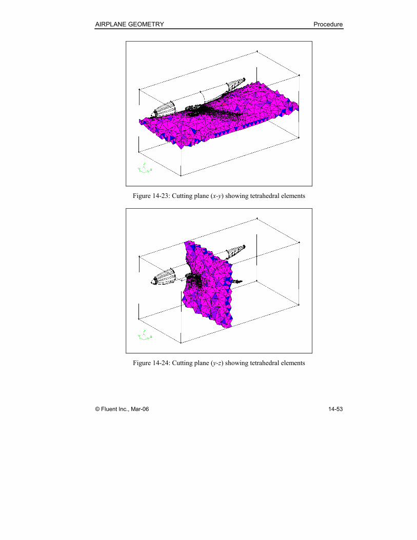
Figure 14-23 and Figure 14-24 show x-y and y-z cutting planes through the mesh.
AIRPLANE GEOMETRY Procedure
© Fluent Inc., Mar-06 14-53
Figure 14-23: Cutting plane (x-y) showing tetrahedral elements
Figure 14-24: Cutting plane (y-z) showing tetrahedral elements
Procedure AIRPLANE GEOMETRY
14-54 © Fluent Inc., Mar-06
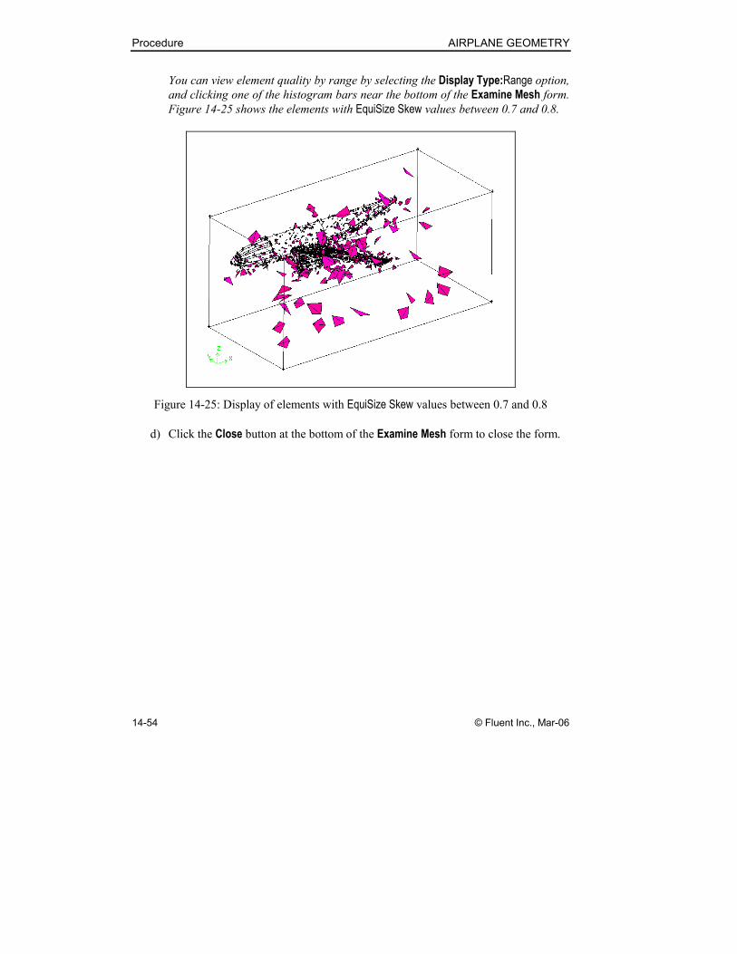
You can view element quality by range by selecting the Display Type:Range option,
and clicking one of the histogram bars near the bottom of the Examine Mesh form.
Figure 14-25 shows the elements with EquiSize Skew values between 0.7 and 0.8.
Figure 14-25: Display of elements with EquiSize Skew values between 0.7 and 0.8
d) Click the Close button at the bottom of the Examine Mesh form to close the form.
AIRPLANE GEOMETRY Procedure
© Fluent Inc., Mar-06 14-55
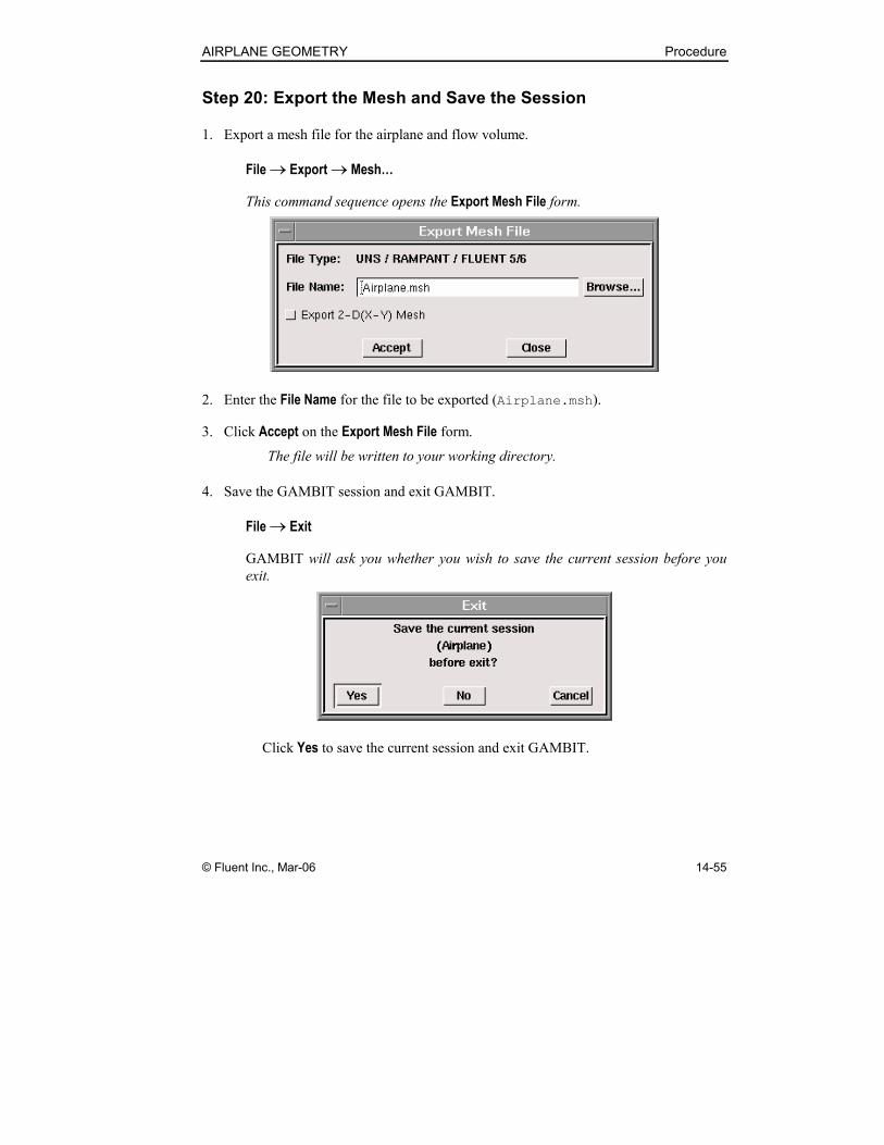
Step 20: Export the Mesh and Save the Session
1. Export a mesh file for the airplane and flow volume.
File → Export → Mesh…
This command sequence opens the Export Mesh File form.
2. Enter the File Name for the file to be exported (Airplane.msh).
3. Click Accept on the Export Mesh File form.
The file will be written to your working directory.
4. Save the GAMBIT session and exit GAMBIT.
File → Exit
GAMBIT will ask you whether you wish to save the current session before you
exit.
Click Yes to save the current session and exit GAMBIT.
Summary AIRPLANE GEOMETRY
14-56 © Fluent Inc., Mar-06
14.5 Summary
This tutorial illustrated how to import geometry from an external CAD package as a STEP
file, use GAMBIT healing and clean-up tools to make the geometry suitable for meshing,
apply size functions, and mesh the geometry.