13216 hi res pdf/diemax_xl.pdfspring selection steps if the diameter and length are known, turn...
TRANSCRIPT
DieMax XLMaximum Life Springs
13216_Danly.P65 4/8/03, 1:53 PM1
DieMax XLTM Maximum Life Springs
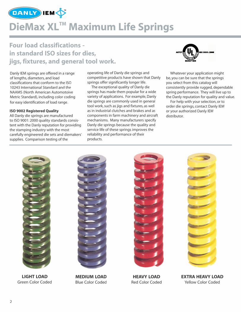
Danly IEM springs are offered in a rangeof lengths, diameters, and loadclassifications that conform to the ISO10243 International Standard and theNAAMS (North American AutomotoiveMetric Standard), including color coding
for easy identification of load range.
Four load classifications -in standard ISO sizes for dies,jigs, fixtures, and general tool work.
ISO 9002 Registered QualityAll Danly die springs are manufacturedto ISO 9001: 2000 quality standards consis-tent with the Danly reputation for providingthe stamping industry with the mostcarefully engineered die sets and diemakers’supplies. Comparison testing of the
operating life of Danly die springs andcompetitive products have shown that Danlysprings offer significantly longer life. The exceptional quality of Danly diesprings has made them popular for a widevariety of applications. For example, Danlydie springs are commonly used in generaltool work, such as jigs and fixtures, as wellas in industrial clutches and brakes and ascomponents in farm machinery and aircraftmechanisms. Many manufacturers specifyDanly die springs because the quality andservice life of these springs improves thereliability and performance of theirproducts.
Whatever your application mightbe, you can be sure that the springsyou select from this catalog willconsistently provide rugged, dependablespring performance. They will live up tothe Danly reputation for quality and value. For help with your selection, or toorder die springs, contact Danly IEMor your authorized Danly IEMdistributor.
LIGHT LOADGreen Color Coded
MEDIUM LOADBlue Color Coded
HEAVY LOADRed Color Coded
EXTRA HEAVY LOADYellow Color Coded
2
13216_Danly.P65 4/8/03, 1:53 PM2
DieMax XLTM Maximum Life Springs -springs you can rely on.
A combination of enhanced raw material,optimal spring design, innovative manufac-turing processes, and broad distributionchannels allow the DieMax XLTM spring toyield the best, most dependable perfor-mance and availability combination, time
after time.
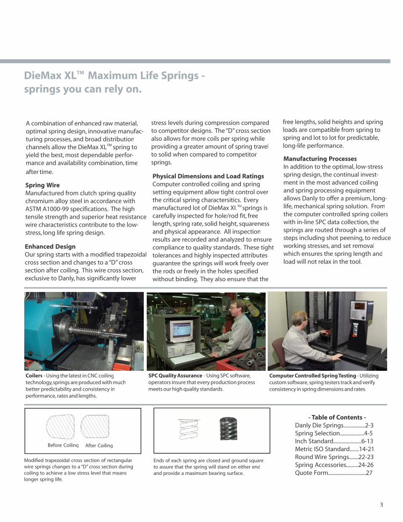
Spring WireManufactured from clutch spring qualitychromium alloy steel in accordance withASTM A1000-99 specifications. The hightensile strength and superior heat resistancewire characteristics contribute to the low-stress, long life spring design.
Enhanced DesignOur spring starts with a modified trapezoidalcross section and changes to a “D” crosssection after coiling. This wire cross section,exclusive to Danly, has significantly lower
stress levels during compression comparedto competitor designs. The “D” cross sectionalso allows for more coils per spring whileproviding a greater amount of spring travelto solid when compared to competitorsprings.
Physical Dimensions and Load RatingsComputer controlled coiling and springsetting equipment allow tight control overthe critical spring charactersitics. Everymanufactured lot of DieMax XLTM springs iscarefully inspected for hole/rod fit, freelength, spring rate, solid height, squarenessand physical appearance. All inspectionresults are recorded and analyzed to ensurecompliance to quality standards. These tighttolerances and highly inspected attributesguarantee the springs will work freely overthe rods or freely in the holes specifiedwithout binding. They also ensure that the
free lengths, solid heights and springloads are compatible from spring tospring and lot to lot for predictable,long-life performance.
Manufacturing ProcessesIn addition to the optimal, low-stressspring design, the continual invest-ment in the most advanced coilingand spring processing equipmentallows Danly to offer a premium, long-life, mechanical spring solution. Fromthe computer controlled spring coilerswith in-line SPC data collection, thesprings are routed through a series ofsteps including shot peening, to reduceworking stresses, and set removalwhich ensures the spring length andload will not relax in the tool.
3
Before Coiling After Coiling
Modified trapezoidal cross section of rectangularwire springs changes to a “D” cross section duringcoiling to achieve a low stress level that meanslonger spring life.
Ends of each spring are closed and ground squareto assure that the spring will stand on either endand provide a maximum bearing surface.
- Table of Contents -Danly Die Springs................2-3Spring Selection..................4-5Inch Standard.....................6-13Metric ISO Standard.......14-21Round Wire Springs.......22-23Spring Accessories.........24-26Quote Form............................27
Coilers - Using the latest in CNC coilingtechnology, springs are produced with muchbetter predictability and consistency inperformance, rates and lengths.
SPC Quality Assurance - Using SPC software,operators insure that every production processmeets our high quality standards.
Computer Controlled Spring Testing - Utilizingcustom software, spring testers track and verifyconsistency in spring dimensions and rates.
13216_DanlyAC1.P65 4/11/03, 3:44 PM3
Spring Selection Steps
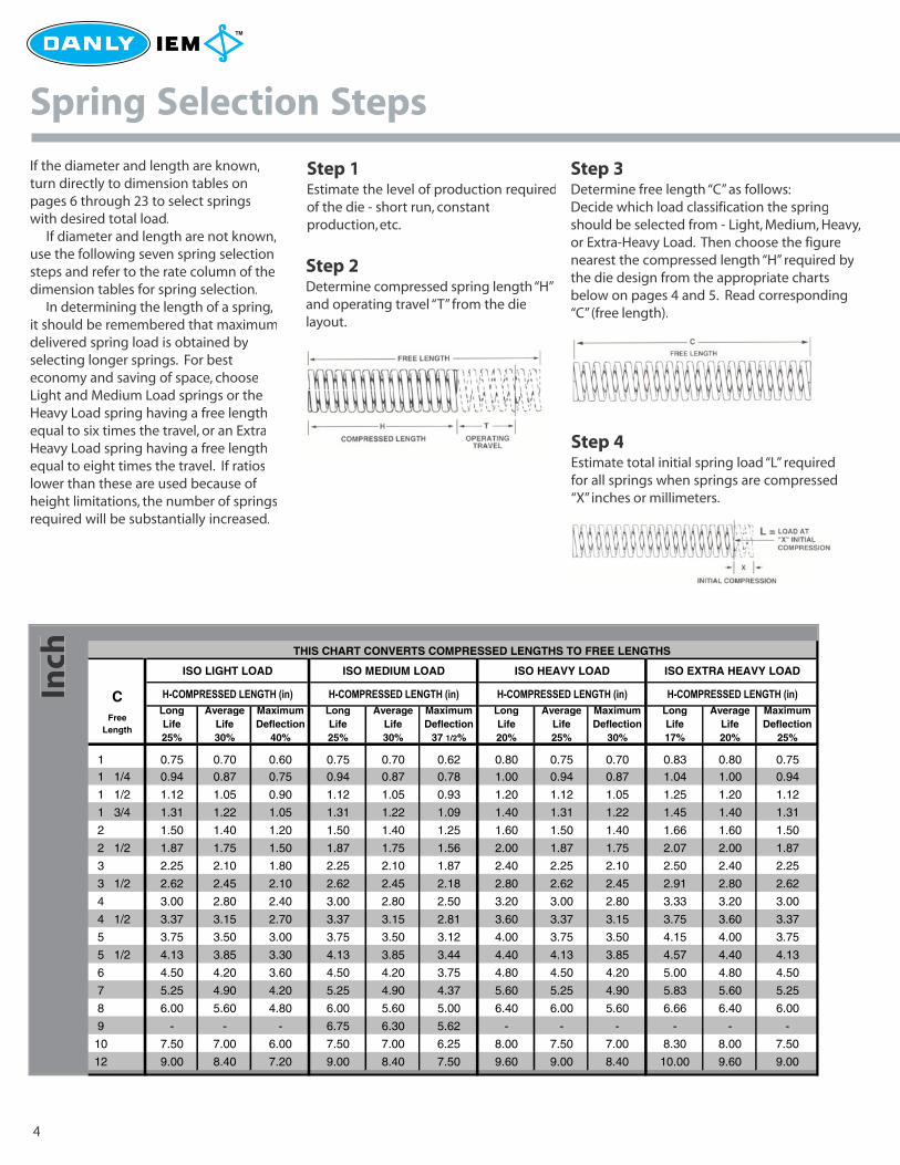
If the diameter and length are known,turn directly to dimension tables onpages 6 through 23 to select springswith desired total load. If diameter and length are not known,use the following seven spring selectionsteps and refer to the rate column of thedimension tables for spring selection. In determining the length of a spring,it should be remembered that maximumdelivered spring load is obtained byselecting longer springs. For besteconomy and saving of space, chooseLight and Medium Load springs or theHeavy Load spring having a free lengthequal to six times the travel, or an ExtraHeavy Load spring having a free lengthequal to eight times the travel. If ratioslower than these are used because ofheight limitations, the number of springsrequired will be substantially increased.
Step 1Estimate the level of production requiredof the die - short run, constantproduction, etc.
Step 3Determine free length “C” as follows:Decide which load classification the springshould be selected from - Light, Medium, Heavy,or Extra-Heavy Load. Then choose the figurenearest the compressed length “H” required bythe die design from the appropriate chartsbelow on pages 4 and 5. Read corresponding“C” (free length).
Step 2Determine compressed spring length “H”and operating travel “T” from the dielayout.
Step 4Estimate total initial spring load “L” requiredfor all springs when springs are compressed“X” inches or millimeters.
4
Inch THIS CHART CONVERTS COMPRESSED LENGTHS TO FREE LENGTHS
ISO LIGHT LOAD ISO MEDIUM LOAD ISO HEAVY LOAD ISO EXTRA HEAVY LOAD
C ������������ �������� ������������ �������� ������������ �������� ������������ ��������
1 0.75 0.70 0.60 0.75 0.70 0.62 0.80 0.75 0.70 0.83 0.80 0.751 1/4 0.94 0.87 0.75 0.94 0.87 0.78 1.00 0.94 0.87 1.04 1.00 0.94
1 1/2 1.12 1.05 0.90 1.12 1.05 0.93 1.20 1.12 1.05 1.25 1.20 1.12
1 3/4 1.31 1.22 1.05 1.31 1.22 1.09 1.40 1.31 1.22 1.45 1.40 1.31
2 1.50 1.40 1.20 1.50 1.40 1.25 1.60 1.50 1.40 1.66 1.60 1.50
2 1/2 1.87 1.75 1.50 1.87 1.75 1.56 2.00 1.87 1.75 2.07 2.00 1.87
3 2.25 2.10 1.80 2.25 2.10 1.87 2.40 2.25 2.10 2.50 2.40 2.25
3 1/2 2.62 2.45 2.10 2.62 2.45 2.18 2.80 2.62 2.45 2.91 2.80 2.62
4 3.00 2.80 2.40 3.00 2.80 2.50 3.20 3.00 2.80 3.33 3.20 3.00
4 1/2 3.37 3.15 2.70 3.37 3.15 2.81 3.60 3.37 3.15 3.75 3.60 3.37
5 3.75 3.50 3.00 3.75 3.50 3.12 4.00 3.75 3.50 4.15 4.00 3.75
5 1/2 4.13 3.85 3.30 4.13 3.85 3.44 4.40 4.13 3.85 4.57 4.40 4.13
6 4.50 4.20 3.60 4.50 4.20 3.75 4.80 4.50 4.20 5.00 4.80 4.50
7 5.25 4.90 4.20 5.25 4.90 4.37 5.60 5.25 4.90 5.83 5.60 5.25
8 6.00 5.60 4.80 6.00 5.60 5.00 6.40 6.00 5.60 6.66 6.40 6.00
9 - - - 6.75 6.30 5.62 - - - - - -
10 7.50 7.00 6.00 7.50 7.00 6.25 8.00 7.50 7.00 8.30 8.00 7.50
12 9.00 8.40 7.20 9.00 8.40 7.50 9.60 9.00 8.40 10.00 9.60 9.00
Free Length
LongLife 20%
AverageLife 25%
Maximum Deflection
30%
Maximum Deflection
37 1/2%
AverageLife 30%
LongLife 25%
LongLife 25%
AverageLife 30%
AverageLife 20%
Maximum Deflection
25%
Maximum Deflection
40%
LongLife 17%
13216_Danly.P65 4/8/03, 1:53 PM4
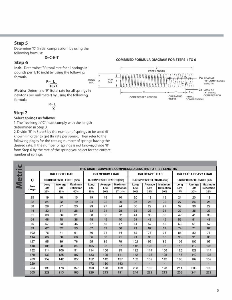
Step 5Determine “X” (initial compression) by using thefollowing formula:
X=C-H-T
Step 6Inch: Determine “R” (total rate for all springs inpounds per 1/10 inch) by using the followingformula: R= L 10xXMetric: Determine “R” (total rate for all springsnewtons per millimeter) by using the followingformula:
R= L XStep 7Select springs as follows:1. The free length “C” must comply with the lengthdetermined in Step 3.2. Divide “R” in Step 6 by the number of springs to be used (ifknown) in order to get thr rate per spring. Then refer to thefollowing pages for the catalog number of springs having thedesired rate. If the number of springs is not known, divide “R”from Step 6 by the rate of the spring you select for the correctnumber of springs.
5
COMBINED FORMULA DIAGRAM FOR STEPS 1 TO 6
Met
ric
THIS CHART CONVERTS COMPRESSED LENGTHS TO FREE LENGTHS
ISO LIGHT LOAD ISO MEDIUM LOAD ISO HEAVY LOAD ISO EXTRA HEAVY LOAD
C ������������ �������� ������������ �������� ������������ �������� ������������ ��������
25 19 18 15 19 18 16 20 19 18 21 20 19
32 24 22 19 24 22 20 26 24 22 27 26 24
38 29 27 23 29 27 24 30 29 27 32 30 29
44 33 31 26 33 31 28 35 33 31 37 35 33
51 38 36 31 38 36 32 41 38 36 42 41 38
64 48 45 38 48 45 40 51 48 45 53 51 4876 57 53 46 57 53 47 61 57 53 63 61 57
89 67 62 53 67 62 56 71 67 62 74 71 67
102 76 71 61 76 71 64 82 76 71 85 82 76
114 86 80 68 86 80 71 91 86 80 95 91 86
127 95 89 76 95 89 79 102 95 89 105 102 95
140 105 98 84 105 98 87 112 105 98 116 112 105
152 114 106 91 114 106 95 122 114 106 126 122 114
178 133 125 107 133 125 111 142 133 125 148 142 133
203 152 142 122 152 142 127 162 152 142 168 162 152229 - - - 172 160 143 - - - - - -
254 190 178 152 190 178 159 203 190 178 211 203 190
305 229 213 183 229 213 191 244 229 213 253 244 229
Free Length
AverageLife 20%
LongLife 17%
Maximum Deflection
25%
AverageLife 25%
Maximum Deflection
30%
LongLife 20%
Maximum Deflection
37 1/2%
AverageLife 30%
LongLife 25%
LongLife 25%
AverageLife 30%
Maximum Deflection
40%
13216_Danly.P65 4/8/03, 1:53 PM5
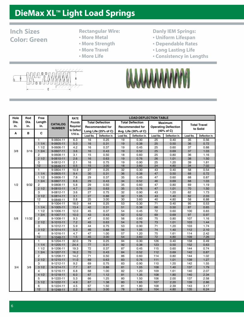
DieMax XLTM Light Load Springs
6
LOAD-DEFLECTION TABLE
�������� ���� ������� �������� ���� ������� �������� ���� ������� �������� ���� �������
1 9-0604-11 6.3 16 0.25 19 0.30 25 0.40 35 0.561 1/4 9-0605-11 5.0 16 0.31 19 0.38 25 0.50 36 0.721 1/2 9-0606-11 4.2 16 0.37 19 0.45 25 0.60 37 0.88
3/8 3/16 1 3/4 9-0607-11 3.6 16 0.43 19 0.52 25 0.69 37 1.032 9-0608-11 3.1 15 0.50 18 0.60 25 0.80 36 1.162 1/2 9-0610-11 2.6 16 0.63 19 0.76 26 1.01 38 1.503 9-0612-11 2.1 16 0.75 19 0.90 25 1.20 39 1.81
12 9-0648-11 0.5 15 3.00 18 3.60 24 4.80 34 7.021 9-0804-11 10.9 27 0.25 32 0.30 43 0.40 58 0.541 1/4 9-0805-11 9.4 30 0.31 36 0.38 47 0.50 68 0.721 1/2 9-0806-11 7.8 29 0.37 35 0.45 47 0.60 68 0.871 3/4 9-0807-11 6.6 29 0.43 34 0.52 46 0.69 68 1.03
1/2 9/32 2 9-0808-11 5.8 29 0.50 35 0.60 47 0.80 69 1.192 1/2 9-0810-11 4.7 29 0.63 35 0.76 47 1.01 70 1.503 9-0812-11 3.6 27 0.75 32 0.90 43 1.20 62 1.733 1/2 9-0814-11 3.1 27 0.88 32 1.05 43 1.40 62 2.03
12 9-0848-11 0.8 25 3.00 30 3.60 40 4.80 58 6.881 9-1004-11 18.0 44 0.25 53 0.30 71 0.40 95 0.531 1/4 9-1005-11 13.4 42 0.31 51 0.38 68 0.50 87 0.651 1/2 9-1006-11 12.0 45 0.37 54 0.45 72 0.60 100 0.831 3/4 9-1007-11 10.0 43 0.43 52 0.52 69 0.69 97 0.97
5/8 11/32 2 9-1008-11 9.3 47 0.50 56 0.60 75 0.80 107 1.162 1/2 9-1010-11 7.2 45 0.63 54 0.76 73 1.01 103 1.443 9-1012-11 5.9 44 0.75 53 0.90 71 1.20 103 1.743 1/2 9-1014-11 5.3 46 0.88 56 1.05 74 1.40 112 2.104 9-1016-11 4.7 47 1.00 57 1.20 75 1.61 114 2.42
12 9-1048-11 1.5 45 3.00 54 3.60 72 4.80 109 7.261 9-1204-11 32.0 79 0.25 94 0.30 126 0.40 158 0.491 1/4 9-1205-11 24.4 77 0.31 92 0.38 123 0.50 152 0.631 1/2 9-1206-11 19.3 72 0.37 87 0.45 115 0.60 144 0.741 3/4 9-1207-11 16.2 70 0.43 84 0.52 112 0.69 142 0.872 9-1208-11 14.2 71 0.50 86 0.60 114 0.80 144 1.022 1/2 9-1210-11 11.0 69 0.63 83 0.76 111 1.01 139 1.273 9-1212-11 9.2 69 0.75 83 0.90 110 1.20 142 1.55
3/4 3/8 3 1/2 9-1214-11 7.7 67 0.88 81 1.05 108 1.40 137 1.794 9-1216-11 6.8 68 1.00 82 1.20 109 1.61 140 2.074 1/2 9-1218-11 6.0 67 1.12 81 1.35 108 1.80 140 2.345 9-1220-11 5.3 66 1.25 80 1.50 106 2.00 137 2.585 1/2 9-1222-11 4.9 67 1.38 80 1.65 107 2.20 139 2.866 9-1224-11 4.5 67 1.50 81 1.80 108 2.39 143 3.17
12 9-1248-11 2.2 65 3.00 78 3.60 104 4.80 135 6.24
Hole Dia. in.
RodDia. in.
Free Length
in.
A B C
Total Travel to Solid
Maximum Operating Deflection
(40% of C)
�����
�������
���������
������� ��
!"!#���$
CATALOG NUMBER
Total DeflectionRecommended for Avg. Life (30% of C)
Total DeflectionRecommended for
Long Life (25% of C)
Inch SizesColor: Green
Rectangular Wire:• More Metal• More Strength• More Travel• More Life
Danly IEM Springs:• Uniform Lifespan• Dependable Rates• Long Lasting Life• Consistency in Lengths
13216_Danly.P65 4/8/03, 1:53 PM6
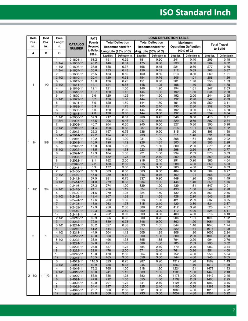
ISO Standard Inch
7
LOAD-DEFLECTION TABLETotal Deflection Total Deflection
Recommended for Recommended for Long Life (25% of C) Avg. Life (30% of C)�������� ���� ������� �������� ���� ������� �������� ���� ������� �������� ���� �������
1 9-1604-11 61.2 151 0.25 181 0.30 241 0.40 296 0.481 1/4 9-1605-11 46.2 146 0.31 175 0.38 233 0.50 284 0.621 1/2 9-1606-11 37.0 138 0.37 166 0.45 221 0.60 277 0.751 3/4 9-1607-11 30.6 133 0.43 159 0.52 212 0.69 268 0.872 9-1608-11 26.5 133 0.50 160 0.60 213 0.80 269 1.012 1/2 9-1610-11 20.4 129 0.63 154 0.76 206 1.01 258 1.263 9-1612-11 16.8 126 0.75 151 0.90 201 1.20 256 1.53
1 1/2 3 1/2 9-1614-11 14.1 124 0.88 148 1.05 198 1.40 251 1.784 9-1616-11 12.1 121 1.00 146 1.20 194 1.61 247 2.034 1/2 9-1618-11 10.7 120 1.12 144 1.35 192 1.80 244 2.285 9-1620-11 9.6 120 1.25 144 1.50 192 2.00 244 2.555 1/2 9-1622-11 8.7 120 1.38 144 1.65 192 2.20 247 2.836 9-1624-11 8.0 120 1.50 144 1.80 191 2.39 250 3.117 9-1628-11 6.9 121 1.75 145 2.10 193 2.80 252 3.658 9-1632-11 6.0 120 2.00 144 2.40 192 3.20 253 4.20
12 9-1648-11 4.0 120 3.00 144 3.60 192 4.80 254 6.341 1/2 9-2006-11 57.9 217 0.37 260 0.45 346 0.60 413 0.711 3/4 9-2007-11 47.5 206 0.43 247 0.52 329 0.69 397 0.842 9-2008-11 40.7 204 0.50 245 0.60 327 0.80 393 0.962 1/2 9-2010-11 31.4 198 0.63 237 0.76 316 1.01 382 1.223 9-2012-11 26.3 197 0.75 236 0.90 315 1.20 395 1.503 1/2 9-2014-11 22.2 194 0.88 233 1.05 311 1.40 391 1.764 9-2016-11 19.2 193 1.00 231 1.20 308 1.61 388 2.02
1 1/4 5/8 4 1/2 9-2018-11 16.9 190 1.12 228 1.35 303 1.80 386 2.285 9-2020-11 15.0 188 1.25 225 1.50 300 2.00 379 2.535 1/2 9-2022-11 13.5 186 1.38 223 1.65 298 2.20 374 2.776 9-2024-11 12.3 184 1.50 221 1.80 294 2.39 373 3.037 9-2028-11 10.4 182 1.75 219 2.10 292 2.80 369 3.538 9-2032-11 9.1 182 2.00 218 2.40 291 3.20 366 4.04
10 9-2040-11 7.2 180 2.50 216 3.00 288 4.00 360 5.0312 9-2048-11 5.9 177 3.00 213 3.60 283 4.80 357 6.032 9-2408-11 60.3 303 0.50 363 0.60 484 0.80 584 0.972 1/2 9-2410-11 45.8 289 0.63 346 0.76 462 1.01 558 1.223 9-2412-11 37.5 281 0.75 337 0.90 449 1.20 558 1.493 1/2 9-2414-11 31.8 279 0.88 334 1.05 446 1.40 559 1.764 9-2416-11 27.3 274 1.00 329 1.20 439 1.61 547 2.01
1 1/2 3/4 4 1/2 9-2418-11 24.1 270 1.12 324 1.35 433 1.80 549 2.285 9-2420-11 21.6 270 1.25 324 1.50 432 2.00 551 2.555 1/2 9-2422-11 19.4 267 1.38 321 1.65 428 2.20 543 2.806 9-2424-11 17.6 263 1.50 316 1.80 421 2.39 537 3.057 9-2428-11 15.0 263 1.75 315 2.10 420 2.80 534 3.578 9-2432-11 12.9 258 2.00 309 2.40 412 3.20 526 4.07
10 9-2440-11 10.3 258 2.50 309 3.00 412 4.00 524 5.1112 9-2448-11 8.4 252 3.00 303 3.60 403 4.80 516 6.102 1/2 9-3210-11 89.9 566 0.63 680 0.76 906 1.01 1096 1.223 9-3212-11 72.0 539 0.75 646 0.90 862 1.20 1064 1.483 1/2 9-3214-11 60.2 527 0.88 633 1.05 844 1.40 1046 1.744 9-3216-11 51.2 514 1.00 617 1.20 822 1.61 1016 1.984 1/2 9-3218-11 44.9 504 1.12 605 1.35 806 1.80 1006 2.24
2 1 5 9-3220-11 40.0 500 1.25 600 1.50 800 2.00 1000 2.505 1/2 9-3222-11 36.0 496 1.38 595 1.65 794 2.20 994 2.766 9-3224-11 32.8 491 1.50 589 1.80 785 2.39 990 3.027 9-3228-11 27.8 487 1.75 584 2.10 779 2.80 983 3.548 9-3232-11 23.8 476 2.00 571 2.40 761 3.20 951 4.00
10 9-3240-11 18.8 470 2.50 564 3.00 752 4.00 950 5.0412 9-3248-11 15.5 465 3.00 558 3.60 744 4.80 940 6.053 9-4012-11 110.0 823 0.75 987 0.90 1317 1.20 1569 1.433 1/2 9-4014-11 89.9 788 0.88 945 1.05 1260 1.40 1512 1.684 9-4016-11 76.2 765 1.00 918 1.20 1224 1.61 1473 1.934 1/2 9-4018-11 66.0 741 1.12 889 1.35 1185 1.80 1440 2.18
2 1/2 1 1/2 5 9-4020-11 58.8 735 1.25 882 1.50 1176 2.00 1442 2.456 9-4024-11 47.6 712 1.50 855 1.80 1139 2.39 1406 2.957 9-4028-11 40.0 701 1.75 841 2.10 1121 2.80 1380 3.458 9-4032-11 34.4 687 2.00 825 2.40 1100 3.20 1362 3.96
10 9-4040-11 26.7 668 2.50 801 3.00 1068 4.00 1316 4.9212 9-4048-11 22.0 660 3.00 793 3.60 1057 4.80 1304 5.92
Maximum Operating Deflection
(40% of C)
Total Travel to Solid
A B C
Hole Dia. in.
RodDia. in.
Free Length
in.CATALOG NUMBER
�����
�������
���������
������� ��
!"!#���$
13216_Danly.P65 4/8/03, 1:53 PM7
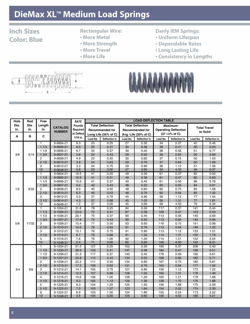
DieMax XLTM Medium Load Springs
8
LOAD-DEFLECTION TABLE
Total Deflection Total DeflectionRecommended for Recommended for
Long Life (25% of C) Avg. Life (30% of C)�������� ���� ������� �������� ���� ������� �������� ���� ������� �������� ���� �������
1 9-0604-21 9.3 23 0.25 27 0.30 34 0.37 42 0.461 1/4 9-0605-21 8.0 25 0.31 30 0.38 38 0.47 50 0.631 1/2 9-0606-21 6.7 25 0.37 30 0.45 38 0.56 51 0.77
3/8 3/16 1 3/4 9-0607-21 5.6 24 0.43 29 0.52 36 0.65 50 0.892 9-0608-21 4.9 25 0.50 30 0.60 37 0.75 50 1.032 1/2 9-0610-21 3.9 24 0.63 29 0.76 37 0.94 50 1.283 9-0612-21 3.3 24 0.75 29 0.90 36 1.12 51 1.56
12 9-0648-21 0.8 23 3.00 27 3.60 34 4.50 46 6.071 9-0804-21 16.5 41 0.25 49 0.30 61 0.37 82 0.501 1/4 9-0805-21 12.9 41 0.31 49 0.38 61 0.47 82 0.631 1/2 9-0806-21 10.9 41 0.37 49 0.45 61 0.56 86 0.781 3/4 9-0807-21 9.2 40 0.43 48 0.52 60 0.65 84 0.91
1/2 9/32 2 9-0808-21 8.0 40 0.50 48 0.60 60 0.75 85 1.062 1/2 9-0810-21 6.3 40 0.63 48 0.76 60 0.94 82 1.323 9-0812-21 5.0 37 0.75 45 0.90 56 1.12 77 1.543 1/2 9-0814-21 4.3 37 0.88 45 1.05 56 1.31 77 1.81
12 9-0848-21 1.2 37 3.00 45 3.60 56 4.50 79 6.351 9-1004-21 31.8 78 0.25 94 0.30 117 0.37 141 0.441 1/4 9-1005-21 23.0 72 0.31 87 0.38 109 0.47 123 0.531 1/2 9-1006-21 20.1 75 0.37 90 0.45 113 0.56 140 0.691 3/4 9-1007-21 17.4 75 0.43 90 0.52 113 0.65 145 0.84
5/8 11/32 2 9-1008-21 15.4 77 0.50 93 0.60 116 0.75 151 0.982 1/2 9-1010-21 12.0 76 0.63 91 0.76 113 0.94 146 1.223 9-1012-21 10.1 76 0.75 91 0.90 113 1.12 153 1.513 1/2 9-1014-21 8.7 76 0.88 91 1.05 114 1.31 155 1.784 9-1016-21 7.6 76 1.00 92 1.20 114 1.51 154 2.04
12 9-1048-21 2.4 71 3.00 85 3.60 106 4.50 142 6.011 9-1204-21 51.5 127 0.25 152 0.30 190 0.37 208 0.401 1/4 9-1205-21 38.9 123 0.31 147 0.38 184 0.47 198 0.511 1/2 9-1206-21 31.3 117 0.37 140 0.45 176 0.56 192 0.611 3/4 9-1207-21 25.8 112 0.43 134 0.52 168 0.65 182 0.712 9-1208-21 22.2 111 0.50 134 0.60 167 0.75 180 0.812 1/2 9-1210-21 17.3 109 0.63 131 0.76 163 0.94 177 1.02
3/4 3/8 3 9-1212-21 14.1 105 0.75 127 0.90 158 1.12 173 1.223 1/2 9-1214-21 12.2 107 0.88 128 1.05 160 1.31 178 1.464 9-1216-21 10.6 106 1.00 128 1.20 160 1.51 179 1.684 1/2 9-1218-21 9.3 105 1.13 126 1.36 158 1.70 175 1.885 9-1220-21 8.3 104 1.25 125 1.50 156 1.88 175 2.095 1/2 9-1222-21 7.5 103 1.37 123 1.64 154 2.05 174 2.306 9-1224-21 6.9 103 1.50 124 1.80 155 2.24 173 2.52
12 9-1248-21 3.5 104 3.00 125 3.60 156 4.50 180 5.21
�����
�������
���������
������� ��
!"!#���$
Maximum Operating Deflection
(37 1/2% of C)
Total Travel to Solid
A B C
Hole Dia. in.
RodDia. in.
Free Length
in. CATALOG NUMBER
Inch SizesColor: Blue
Rectangular Wire:• More Metal• More Strength• More Travel• More Life
Danly IEM Springs:• Uniform Lifespan• Dependable Rates• Long Lasting Life• Consistency in Lengths
13216_Danly.P65 4/8/03, 1:53 PM8
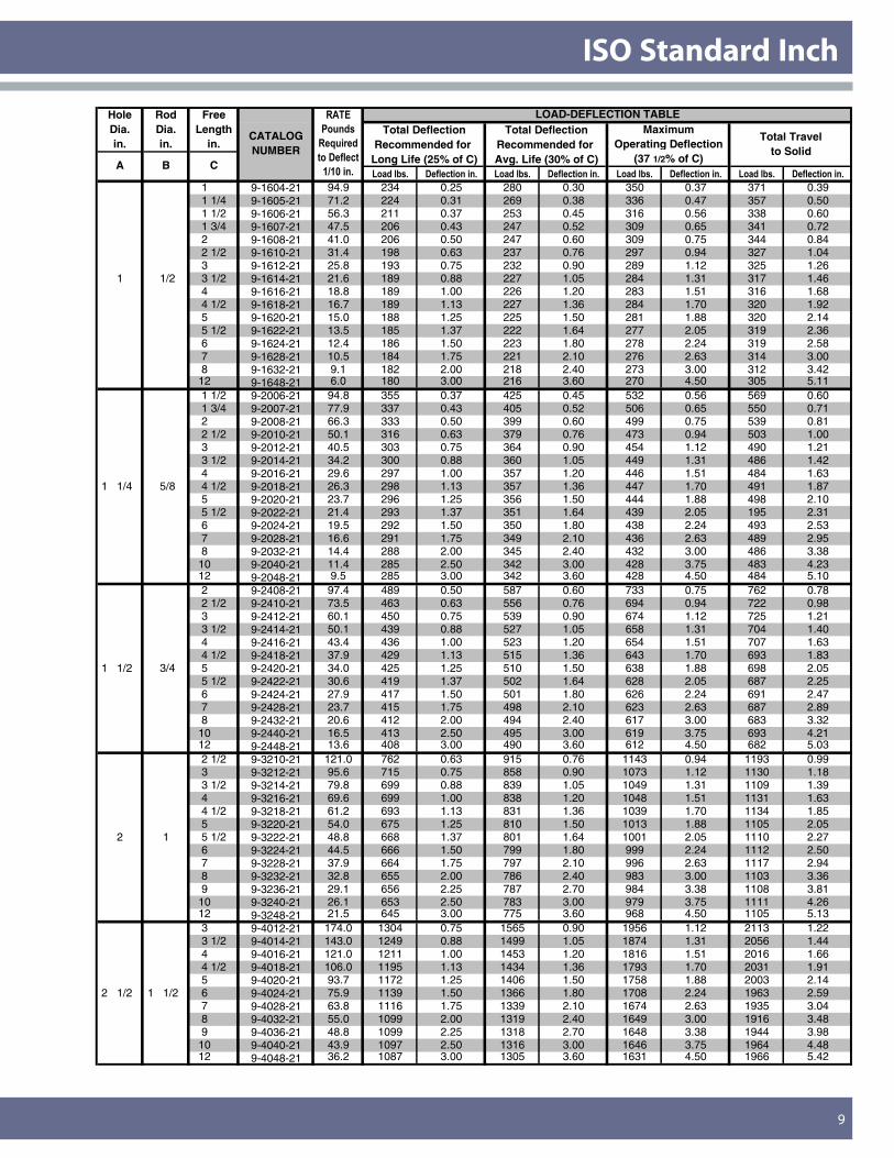
ISO Standard Inch
9
LOAD-DEFLECTION TABLETotal Deflection Total Deflection
Recommended for Recommended for Long Life (25% of C) Avg. Life (30% of C)�������� ���� ������� �������� ���� ������� �������� ���� ������� �������� ���� �������
1 9-1604-21 94.9 234 0.25 280 0.30 350 0.37 371 0.391 1/4 9-1605-21 71.2 224 0.31 269 0.38 336 0.47 357 0.501 1/2 9-1606-21 56.3 211 0.37 253 0.45 316 0.56 338 0.601 3/4 9-1607-21 47.5 206 0.43 247 0.52 309 0.65 341 0.722 9-1608-21 41.0 206 0.50 247 0.60 309 0.75 344 0.842 1/2 9-1610-21 31.4 198 0.63 237 0.76 297 0.94 327 1.043 9-1612-21 25.8 193 0.75 232 0.90 289 1.12 325 1.26
1 1/2 3 1/2 9-1614-21 21.6 189 0.88 227 1.05 284 1.31 317 1.464 9-1616-21 18.8 189 1.00 226 1.20 283 1.51 316 1.684 1/2 9-1618-21 16.7 189 1.13 227 1.36 284 1.70 320 1.925 9-1620-21 15.0 188 1.25 225 1.50 281 1.88 320 2.145 1/2 9-1622-21 13.5 185 1.37 222 1.64 277 2.05 319 2.366 9-1624-21 12.4 186 1.50 223 1.80 278 2.24 319 2.587 9-1628-21 10.5 184 1.75 221 2.10 276 2.63 314 3.008 9-1632-21 9.1 182 2.00 218 2.40 273 3.00 312 3.42
12 9-1648-21 6.0 180 3.00 216 3.60 270 4.50 305 5.111 1/2 9-2006-21 94.8 355 0.37 425 0.45 532 0.56 569 0.601 3/4 9-2007-21 77.9 337 0.43 405 0.52 506 0.65 550 0.712 9-2008-21 66.3 333 0.50 399 0.60 499 0.75 539 0.812 1/2 9-2010-21 50.1 316 0.63 379 0.76 473 0.94 503 1.003 9-2012-21 40.5 303 0.75 364 0.90 454 1.12 490 1.213 1/2 9-2014-21 34.2 300 0.88 360 1.05 449 1.31 486 1.424 9-2016-21 29.6 297 1.00 357 1.20 446 1.51 484 1.63
1 1/4 5/8 4 1/2 9-2018-21 26.3 298 1.13 357 1.36 447 1.70 491 1.875 9-2020-21 23.7 296 1.25 356 1.50 444 1.88 498 2.105 1/2 9-2022-21 21.4 293 1.37 351 1.64 439 2.05 195 2.316 9-2024-21 19.5 292 1.50 350 1.80 438 2.24 493 2.537 9-2028-21 16.6 291 1.75 349 2.10 436 2.63 489 2.958 9-2032-21 14.4 288 2.00 345 2.40 432 3.00 486 3.38
10 9-2040-21 11.4 285 2.50 342 3.00 428 3.75 483 4.2312 9-2048-21 9.5 285 3.00 342 3.60 428 4.50 484 5.102 9-2408-21 97.4 489 0.50 587 0.60 733 0.75 762 0.782 1/2 9-2410-21 73.5 463 0.63 556 0.76 694 0.94 722 0.983 9-2412-21 60.1 450 0.75 539 0.90 674 1.12 725 1.213 1/2 9-2414-21 50.1 439 0.88 527 1.05 658 1.31 704 1.404 9-2416-21 43.4 436 1.00 523 1.20 654 1.51 707 1.634 1/2 9-2418-21 37.9 429 1.13 515 1.36 643 1.70 693 1.83
1 1/2 3/4 5 9-2420-21 34.0 425 1.25 510 1.50 638 1.88 698 2.055 1/2 9-2422-21 30.6 419 1.37 502 1.64 628 2.05 687 2.256 9-2424-21 27.9 417 1.50 501 1.80 626 2.24 691 2.477 9-2428-21 23.7 415 1.75 498 2.10 623 2.63 687 2.898 9-2432-21 20.6 412 2.00 494 2.40 617 3.00 683 3.32
10 9-2440-21 16.5 413 2.50 495 3.00 619 3.75 693 4.2112 9-2448-21 13.6 408 3.00 490 3.60 612 4.50 682 5.032 1/2 9-3210-21 121.0 762 0.63 915 0.76 1143 0.94 1193 0.993 9-3212-21 95.6 715 0.75 858 0.90 1073 1.12 1130 1.183 1/2 9-3214-21 79.8 699 0.88 839 1.05 1049 1.31 1109 1.394 9-3216-21 69.6 699 1.00 838 1.20 1048 1.51 1131 1.634 1/2 9-3218-21 61.2 693 1.13 831 1.36 1039 1.70 1134 1.855 9-3220-21 54.0 675 1.25 810 1.50 1013 1.88 1105 2.05
2 1 5 1/2 9-3222-21 48.8 668 1.37 801 1.64 1001 2.05 1110 2.276 9-3224-21 44.5 666 1.50 799 1.80 999 2.24 1112 2.507 9-3228-21 37.9 664 1.75 797 2.10 996 2.63 1117 2.948 9-3232-21 32.8 655 2.00 786 2.40 983 3.00 1103 3.369 9-3236-21 29.1 656 2.25 787 2.70 984 3.38 1108 3.81
10 9-3240-21 26.1 653 2.50 783 3.00 979 3.75 1111 4.2612 9-3248-21 21.5 645 3.00 775 3.60 968 4.50 1105 5.133 9-4012-21 174.0 1304 0.75 1565 0.90 1956 1.12 2113 1.223 1/2 9-4014-21 143.0 1249 0.88 1499 1.05 1874 1.31 2056 1.444 9-4016-21 121.0 1211 1.00 1453 1.20 1816 1.51 2016 1.664 1/2 9-4018-21 106.0 1195 1.13 1434 1.36 1793 1.70 2031 1.915 9-4020-21 93.7 1172 1.25 1406 1.50 1758 1.88 2003 2.14
2 1/2 1 1/2 6 9-4024-21 75.9 1139 1.50 1366 1.80 1708 2.24 1963 2.597 9-4028-21 63.8 1116 1.75 1339 2.10 1674 2.63 1935 3.048 9-4032-21 55.0 1099 2.00 1319 2.40 1649 3.00 1916 3.489 9-4036-21 48.8 1099 2.25 1318 2.70 1648 3.38 1944 3.98
10 9-4040-21 43.9 1097 2.50 1316 3.00 1646 3.75 1964 4.4812 9-4048-21 36.2 1087 3.00 1305 3.60 1631 4.50 1966 5.42
�����
�������
���������
������� ��
!"!#���$
Maximum Operating Deflection
(37 1/2% of C)
Total Travel to Solid
A B C
Hole Dia. in.
RodDia. in.
Free Length
in.CATALOG NUMBER
13216_Danly.P65 4/8/03, 1:53 PM9
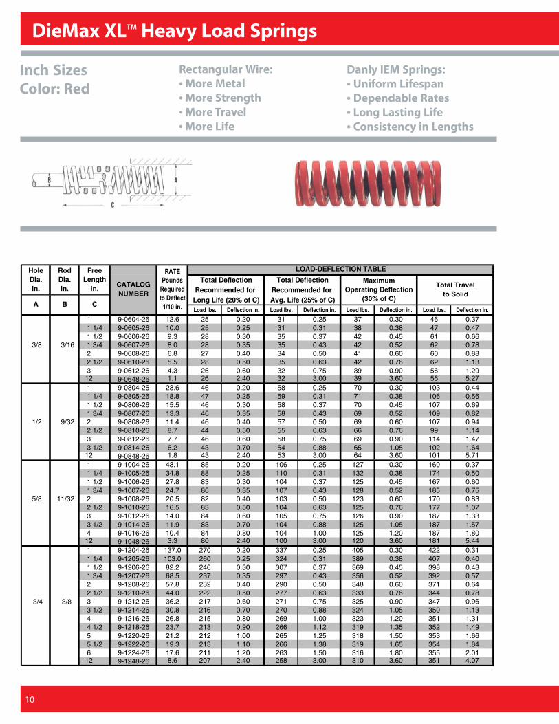
DieMax XLTM Heavy Load Springs
10
LOAD-DEFLECTION TABLE
Total Deflection Total DeflectionRecommended for Recommended for
Long Life (20% of C) Avg. Life (25% of C)�������� ���� ������� �������� ���� ������� �������� ���� ������� �������� ���� �������
1 9-0604-26 12.6 25 0.20 31 0.25 37 0.30 46 0.371 1/4 9-0605-26 10.0 25 0.25 31 0.31 38 0.38 47 0.471 1/2 9-0606-26 9.3 28 0.30 35 0.37 42 0.45 61 0.66
3/8 3/16 1 3/4 9-0607-26 8.0 28 0.35 35 0.43 42 0.52 62 0.782 9-0608-26 6.8 27 0.40 34 0.50 41 0.60 60 0.882 1/2 9-0610-26 5.5 28 0.50 35 0.63 42 0.76 62 1.133 9-0612-26 4.3 26 0.60 32 0.75 39 0.90 56 1.29
12 9-0648-26 1.1 26 2.40 32 3.00 39 3.60 56 5.271 9-0804-26 23.6 46 0.20 58 0.25 70 0.30 103 0.441 1/4 9-0805-26 18.8 47 0.25 59 0.31 71 0.38 106 0.561 1/2 9-0806-26 15.5 46 0.30 58 0.37 70 0.45 107 0.691 3/4 9-0807-26 13.3 46 0.35 58 0.43 69 0.52 109 0.82
1/2 9/32 2 9-0808-26 11.4 46 0.40 57 0.50 69 0.60 107 0.942 1/2 9-0810-26 8.7 44 0.50 55 0.63 66 0.76 99 1.143 9-0812-26 7.7 46 0.60 58 0.75 69 0.90 114 1.473 1/2 9-0814-26 6.2 43 0.70 54 0.88 65 1.05 102 1.64
12 9-0848-26 1.8 43 2.40 53 3.00 64 3.60 101 5.711 9-1004-26 43.1 85 0.20 106 0.25 127 0.30 160 0.371 1/4 9-1005-26 34.8 88 0.25 110 0.31 132 0.38 174 0.501 1/2 9-1006-26 27.8 83 0.30 104 0.37 125 0.45 167 0.601 3/4 9-1007-26 24.7 86 0.35 107 0.43 128 0.52 185 0.75
5/8 11/32 2 9-1008-26 20.5 82 0.40 103 0.50 123 0.60 170 0.832 1/2 9-1010-26 16.5 83 0.50 104 0.63 125 0.76 177 1.073 9-1012-26 14.0 84 0.60 105 0.75 126 0.90 187 1.333 1/2 9-1014-26 11.9 83 0.70 104 0.88 125 1.05 187 1.574 9-1016-26 10.4 84 0.80 104 1.00 125 1.20 187 1.80
12 9-1048-26 3.3 80 2.40 100 3.00 120 3.60 181 5.441 9-1204-26 137.0 270 0.20 337 0.25 405 0.30 422 0.311 1/4 9-1205-26 103.0 260 0.25 324 0.31 389 0.38 407 0.401 1/2 9-1206-26 82.2 246 0.30 307 0.37 369 0.45 398 0.481 3/4 9-1207-26 68.5 237 0.35 297 0.43 356 0.52 392 0.572 9-1208-26 57.8 232 0.40 290 0.50 348 0.60 371 0.642 1/2 9-1210-26 44.0 222 0.50 277 0.63 333 0.76 344 0.78
3/4 3/8 3 9-1212-26 36.2 217 0.60 271 0.75 325 0.90 347 0.963 1/2 9-1214-26 30.8 216 0.70 270 0.88 324 1.05 350 1.134 9-1216-26 26.8 215 0.80 269 1.00 323 1.20 351 1.314 1/2 9-1218-26 23.7 213 0.90 266 1.12 319 1.35 352 1.495 9-1220-26 21.2 212 1.00 265 1.25 318 1.50 353 1.665 1/2 9-1222-26 19.3 213 1.10 266 1.38 319 1.65 354 1.846 9-1224-26 17.6 211 1.20 263 1.50 316 1.80 355 2.01
12 9-1248-26 8.6 207 2.40 258 3.00 310 3.60 351 4.07
�����
�������
���������
������� ��
!"!#���$
Maximum Operating Deflection
(30% of C)
Total Travel to Solid
A B C
Hole Dia. in.
RodDia. in.
Free Length
in. CATALOG NUMBER
Inch SizesColor: Red
Rectangular Wire:• More Metal• More Strength• More Travel• More Life
Danly IEM Springs:• Uniform Lifespan• Dependable Rates• Long Lasting Life• Consistency in Lengths
13216_Danly.P65 4/8/03, 1:53 PM10
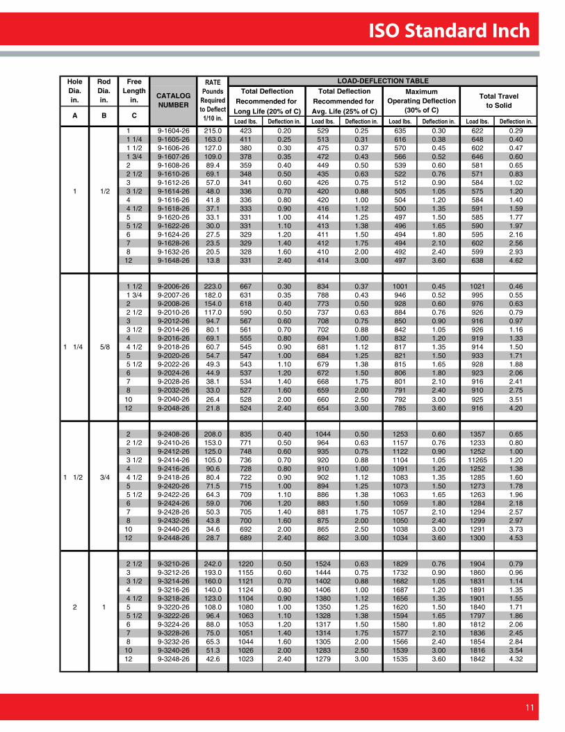
ISO Standard Inch
11
LOAD-DEFLECTION TABLETotal Deflection Total Deflection
Recommended for Recommended for Long Life (20% of C) Avg. Life (25% of C)�������� ���� ������� �������� ���� ������� �������� ���� ������� �������� ���� �������
1 9-1604-26 215.0 423 0.20 529 0.25 635 0.30 622 0.291 1/4 9-1605-26 163.0 411 0.25 513 0.31 616 0.38 648 0.401 1/2 9-1606-26 127.0 380 0.30 475 0.37 570 0.45 602 0.471 3/4 9-1607-26 109.0 378 0.35 472 0.43 566 0.52 646 0.602 9-1608-26 89.4 359 0.40 449 0.50 539 0.60 581 0.652 1/2 9-1610-26 69.1 348 0.50 435 0.63 522 0.76 571 0.833 9-1612-26 57.0 341 0.60 426 0.75 512 0.90 584 1.02
1 1/2 3 1/2 9-1614-26 48.0 336 0.70 420 0.88 505 1.05 575 1.204 9-1616-26 41.8 336 0.80 420 1.00 504 1.20 584 1.404 1/2 9-1618-26 37.1 333 0.90 416 1.12 500 1.35 591 1.595 9-1620-26 33.1 331 1.00 414 1.25 497 1.50 585 1.775 1/2 9-1622-26 30.0 331 1.10 413 1.38 496 1.65 590 1.976 9-1624-26 27.5 329 1.20 411 1.50 494 1.80 595 2.167 9-1628-26 23.5 329 1.40 412 1.75 494 2.10 602 2.568 9-1632-26 20.5 328 1.60 410 2.00 492 2.40 599 2.93
12 9-1648-26 13.8 331 2.40 414 3.00 497 3.60 638 4.62
1 1/2 9-2006-26 223.0 667 0.30 834 0.37 1001 0.45 1021 0.461 3/4 9-2007-26 182.0 631 0.35 788 0.43 946 0.52 995 0.552 9-2008-26 154.0 618 0.40 773 0.50 928 0.60 976 0.632 1/2 9-2010-26 117.0 590 0.50 737 0.63 884 0.76 926 0.793 9-2012-26 94.7 567 0.60 708 0.75 850 0.90 916 0.973 1/2 9-2014-26 80.1 561 0.70 702 0.88 842 1.05 926 1.164 9-2016-26 69.1 555 0.80 694 1.00 832 1.20 919 1.33
1 1/4 5/8 4 1/2 9-2018-26 60.7 545 0.90 681 1.12 817 1.35 914 1.505 9-2020-26 54.7 547 1.00 684 1.25 821 1.50 933 1.715 1/2 9-2022-26 49.3 543 1.10 679 1.38 815 1.65 928 1.886 9-2024-26 44.9 537 1.20 672 1.50 806 1.80 923 2.067 9-2028-26 38.1 534 1.40 668 1.75 801 2.10 916 2.418 9-2032-26 33.0 527 1.60 659 2.00 791 2.40 910 2.75
10 9-2040-26 26.4 528 2.00 660 2.50 792 3.00 925 3.5112 9-2048-26 21.8 524 2.40 654 3.00 785 3.60 916 4.20
2 9-2408-26 208.0 835 0.40 1044 0.50 1253 0.60 1357 0.652 1/2 9-2410-26 153.0 771 0.50 964 0.63 1157 0.76 1233 0.803 9-2412-26 125.0 748 0.60 935 0.75 1122 0.90 1252 1.003 1/2 9-2414-26 105.0 736 0.70 920 0.88 1104 1.05 11265 1.204 9-2416-26 90.6 728 0.80 910 1.00 1091 1.20 1252 1.38
1 1/2 3/4 4 1/2 9-2418-26 80.4 722 0.90 902 1.12 1083 1.35 1285 1.605 9-2420-26 71.5 715 1.00 894 1.25 1073 1.50 1273 1.785 1/2 9-2422-26 64.3 709 1.10 886 1.38 1063 1.65 1263 1.966 9-2424-26 59.0 706 1.20 883 1.50 1059 1.80 1284 2.187 9-2428-26 50.3 705 1.40 881 1.75 1057 2.10 1294 2.578 9-2432-26 43.8 700 1.60 875 2.00 1050 2.40 1299 2.97
10 9-2440-26 34.6 692 2.00 865 2.50 1038 3.00 1291 3.7312 9-2448-26 28.7 689 2.40 862 3.00 1034 3.60 1300 4.53
2 1/2 9-3210-26 242.0 1220 0.50 1524 0.63 1829 0.76 1904 0.793 9-3212-26 193.0 1155 0.60 1444 0.75 1732 0.90 1860 0.963 1/2 9-3214-26 160.0 1121 0.70 1402 0.88 1682 1.05 1831 1.144 9-3216-26 140.0 1124 0.80 1406 1.00 1687 1.20 1891 1.354 1/2 9-3218-26 123.0 1104 0.90 1380 1.12 1656 1.35 1901 1.55
2 1 5 9-3220-26 108.0 1080 1.00 1350 1.25 1620 1.50 1840 1.715 1/2 9-3222-26 96.4 1063 1.10 1328 1.38 1594 1.65 1797 1.866 9-3224-26 88.0 1053 1.20 1317 1.50 1580 1.80 1812 2.067 9-3228-26 75.0 1051 1.40 1314 1.75 1577 2.10 1836 2.458 9-3232-26 65.3 1044 1.60 1305 2.00 1566 2.40 1854 2.84
10 9-3240-26 51.3 1026 2.00 1283 2.50 1539 3.00 1816 3.5412 9-3248-26 42.6 1023 2.40 1279 3.00 1535 3.60 1842 4.32
�����
�������
���������
������� ��
!"!#���$
Maximum Operating Deflection
(30% of C)
Total Travel to Solid
A B C
Hole Dia. in.
RodDia. in.
Free Length
in.CATALOG NUMBER
13216_Danly.P65 4/8/03, 1:53 PM11
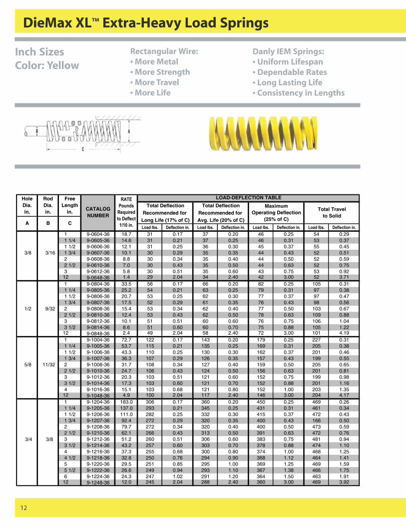
DieMax XLTM Extra-Heavy Load Springs
12
LOAD-DEFLECTION TABLE
Total Deflection Total DeflectionRecommended for Recommended for
Long Life (17% of C) Avg. Life (20% of C)�������� ���� ������� �������� ���� ������� �������� ���� ������� �������� ���� �������
1 9-0604-36 18.7 31 0.17 37 0.20 46 0.25 54 0.291 1/4 9-0605-36 14.6 31 0.21 37 0.25 46 0.31 53 0.371 1/2 9-0606-36 12.1 31 0.25 36 0.30 45 0.37 55 0.45
3/8 3/16 1 3/4 9-0607-36 10.1 30 0.29 35 0.35 44 0.43 52 0.512 9-0608-36 8.8 30 0.34 35 0.40 44 0.50 52 0.592 1/2 9-0610-36 7.0 30 0.43 35 0.50 44 0.63 52 0.753 9-0612-36 5.8 30 0.51 35 0.60 43 0.75 53 0.92
12 9-0648-36 1.4 29 2.04 34 2.40 42 3.00 52 3.711 9-0804-36 33.5 56 0.17 66 0.20 82 0.25 105 0.311 1/4 9-0805-36 25.2 54 0.21 63 0.25 79 0.31 97 0.381 1/2 9-0806-36 20.7 53 0.25 62 0.30 77 0.37 97 0.471 3/4 9-0807-36 17.5 52 0.29 61 0.35 76 0.43 98 0.56
1/2 9/32 2 9-0808-36 15.4 53 0.34 62 0.40 77 0.50 103 0.672 1/2 9-0810-36 12.4 53 0.43 62 0.50 78 0.63 109 0.883 9-0812-36 10.1 51 0.51 60 0.60 76 0.75 106 1.043 1/2 9-0814-36 8.6 51 0.60 60 0.70 75 0.88 105 1.22
12 9-0848-36 2.4 49 2.04 58 2.40 72 3.00 101 4.191 9-1004-36 72.7 122 0.17 143 0.20 179 0.25 227 0.311 1/4 9-1005-36 53.7 115 0.21 135 0.25 169 0.31 205 0.381 1/2 9-1006-36 43.3 110 0.25 130 0.30 162 0.37 201 0.461 3/4 9-1007-36 36.3 107 0.29 126 0.35 157 0.43 199 0.55
5/8 11/32 2 9-1008-36 31.7 108 0.34 127 0.40 159 0.50 205 0.652 1/2 9-1010-36 24.7 106 0.43 124 0.50 156 0.63 201 0.813 9-1012-36 20.3 103 0.51 121 0.60 152 0.75 199 0.983 1/2 9-1014-36 17.3 103 0.60 121 0.70 152 0.88 201 1.164 9-1016-36 15.1 103 0.68 121 0.80 152 1.00 203 1.35
12 9-1048-36 4.9 100 2.04 117 2.40 146 3.00 204 4.171 9-1204-36 183.0 306 0.17 360 0.20 450 0.25 469 0.261 1/4 9-1205-36 137.0 293 0.21 345 0.25 431 0.31 461 0.341 1/2 9-1206-36 111.0 282 0.25 332 0.30 415 0.37 472 0.431 3/4 9-1207-36 92.4 272 0.29 320 0.35 400 0.43 166 0.502 9-1208-36 79.7 272 0.34 320 0.40 400 0.50 473 0.592 1/2 9-1210-36 62.1 266 0.43 313 0.50 391 0.63 472 0.76
3/4 3/8 3 9-1212-36 51.2 260 0.51 306 0.60 383 0.75 481 0.943 1/2 9-1214-36 43.2 257 0.60 303 0.70 378 0.88 474 1.104 9-1216-36 37.3 255 0.68 300 0.80 374 1.00 468 1.254 1/2 9-1218-36 32.8 250 0.76 294 0.90 368 1.12 464 1.415 9-1220-36 29.5 251 0.85 295 1.00 369 1.25 469 1.595 1/2 9-1222-36 26.6 249 0.94 293 1.10 367 1.38 466 1.756 9-1224-36 24.3 247 1.02 291 1.20 364 1.50 463 1.91
12 9-1248-36 12.0 245 2.04 288 2.40 360 3.00 469 3.92
�����
�������
���������
������� ��
!"!#���$
Maximum Operating Deflection
(25% of C)
Total Travel to Solid
A B C
Hole Dia. in.
RodDia. in.
Free Length
in. CATALOG NUMBER
Inch SizesColor: Yellow
Rectangular Wire:• More Metal• More Strength• More Travel• More Life
Danly IEM Springs:• Uniform Lifespan• Dependable Rates• Long Lasting Life• Consistency in Lengths
13216_Danly.P65 4/8/03, 1:53 PM12
ISO Standard Inch
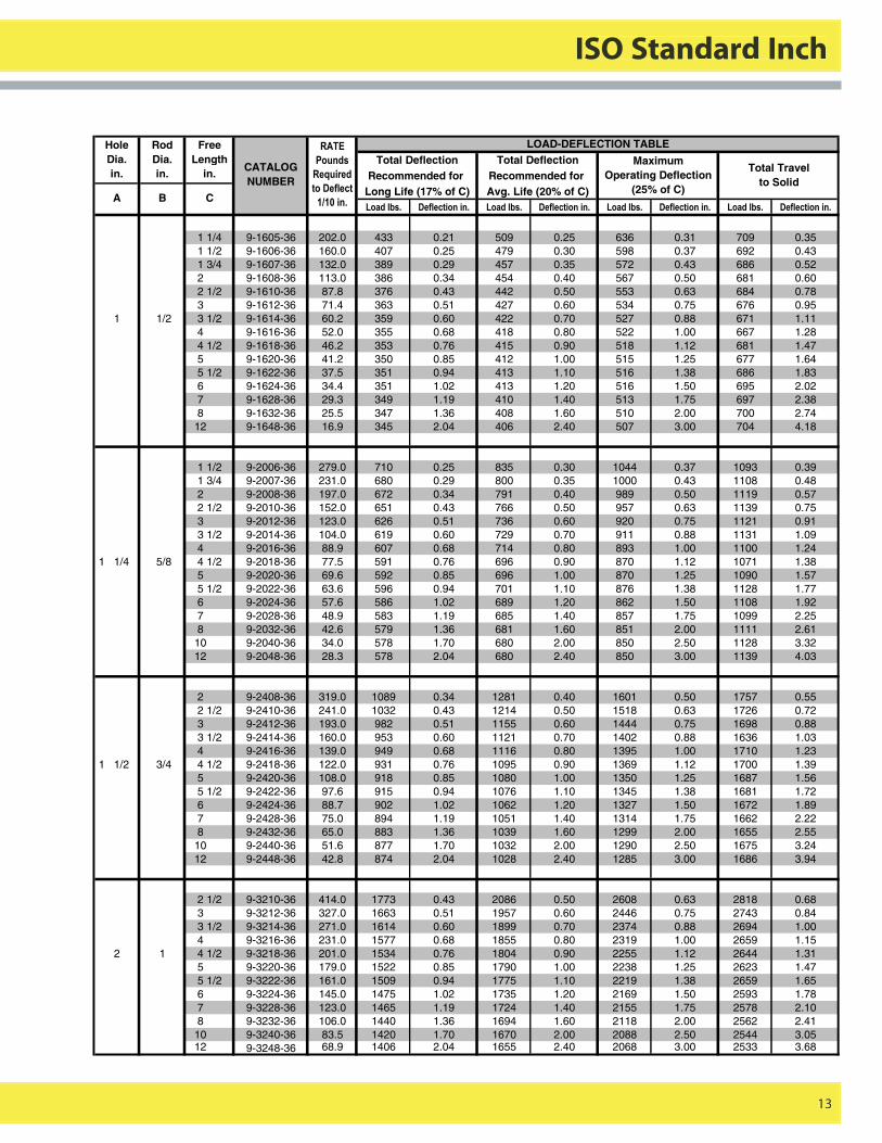
13
LOAD-DEFLECTION TABLETotal Deflection Total Deflection
Recommended for Recommended for Long Life (17% of C) Avg. Life (20% of C)�������� ���� ������� �������� ���� ������� �������� ���� ������� �������� ���� �������
1 1/4 9-1605-36 202.0 433 0.21 509 0.25 636 0.31 709 0.351 1/2 9-1606-36 160.0 407 0.25 479 0.30 598 0.37 692 0.431 3/4 9-1607-36 132.0 389 0.29 457 0.35 572 0.43 686 0.522 9-1608-36 113.0 386 0.34 454 0.40 567 0.50 681 0.602 1/2 9-1610-36 87.8 376 0.43 442 0.50 553 0.63 684 0.783 9-1612-36 71.4 363 0.51 427 0.60 534 0.75 676 0.95
1 1/2 3 1/2 9-1614-36 60.2 359 0.60 422 0.70 527 0.88 671 1.114 9-1616-36 52.0 355 0.68 418 0.80 522 1.00 667 1.284 1/2 9-1618-36 46.2 353 0.76 415 0.90 518 1.12 681 1.475 9-1620-36 41.2 350 0.85 412 1.00 515 1.25 677 1.645 1/2 9-1622-36 37.5 351 0.94 413 1.10 516 1.38 686 1.836 9-1624-36 34.4 351 1.02 413 1.20 516 1.50 695 2.027 9-1628-36 29.3 349 1.19 410 1.40 513 1.75 697 2.388 9-1632-36 25.5 347 1.36 408 1.60 510 2.00 700 2.74
12 9-1648-36 16.9 345 2.04 406 2.40 507 3.00 704 4.18
1 1/2 9-2006-36 279.0 710 0.25 835 0.30 1044 0.37 1093 0.391 3/4 9-2007-36 231.0 680 0.29 800 0.35 1000 0.43 1108 0.482 9-2008-36 197.0 672 0.34 791 0.40 989 0.50 1119 0.572 1/2 9-2010-36 152.0 651 0.43 766 0.50 957 0.63 1139 0.753 9-2012-36 123.0 626 0.51 736 0.60 920 0.75 1121 0.913 1/2 9-2014-36 104.0 619 0.60 729 0.70 911 0.88 1131 1.094 9-2016-36 88.9 607 0.68 714 0.80 893 1.00 1100 1.24
1 1/4 5/8 4 1/2 9-2018-36 77.5 591 0.76 696 0.90 870 1.12 1071 1.385 9-2020-36 69.6 592 0.85 696 1.00 870 1.25 1090 1.575 1/2 9-2022-36 63.6 596 0.94 701 1.10 876 1.38 1128 1.776 9-2024-36 57.6 586 1.02 689 1.20 862 1.50 1108 1.927 9-2028-36 48.9 583 1.19 685 1.40 857 1.75 1099 2.258 9-2032-36 42.6 579 1.36 681 1.60 851 2.00 1111 2.61
10 9-2040-36 34.0 578 1.70 680 2.00 850 2.50 1128 3.3212 9-2048-36 28.3 578 2.04 680 2.40 850 3.00 1139 4.03
2 9-2408-36 319.0 1089 0.34 1281 0.40 1601 0.50 1757 0.552 1/2 9-2410-36 241.0 1032 0.43 1214 0.50 1518 0.63 1726 0.723 9-2412-36 193.0 982 0.51 1155 0.60 1444 0.75 1698 0.883 1/2 9-2414-36 160.0 953 0.60 1121 0.70 1402 0.88 1636 1.034 9-2416-36 139.0 949 0.68 1116 0.80 1395 1.00 1710 1.23
1 1/2 3/4 4 1/2 9-2418-36 122.0 931 0.76 1095 0.90 1369 1.12 1700 1.395 9-2420-36 108.0 918 0.85 1080 1.00 1350 1.25 1687 1.565 1/2 9-2422-36 97.6 915 0.94 1076 1.10 1345 1.38 1681 1.726 9-2424-36 88.7 902 1.02 1062 1.20 1327 1.50 1672 1.897 9-2428-36 75.0 894 1.19 1051 1.40 1314 1.75 1662 2.228 9-2432-36 65.0 883 1.36 1039 1.60 1299 2.00 1655 2.55
10 9-2440-36 51.6 877 1.70 1032 2.00 1290 2.50 1675 3.2412 9-2448-36 42.8 874 2.04 1028 2.40 1285 3.00 1686 3.94
2 1/2 9-3210-36 414.0 1773 0.43 2086 0.50 2608 0.63 2818 0.683 9-3212-36 327.0 1663 0.51 1957 0.60 2446 0.75 2743 0.843 1/2 9-3214-36 271.0 1614 0.60 1899 0.70 2374 0.88 2694 1.004 9-3216-36 231.0 1577 0.68 1855 0.80 2319 1.00 2659 1.15
2 1 4 1/2 9-3218-36 201.0 1534 0.76 1804 0.90 2255 1.12 2644 1.315 9-3220-36 179.0 1522 0.85 1790 1.00 2238 1.25 2623 1.475 1/2 9-3222-36 161.0 1509 0.94 1775 1.10 2219 1.38 2659 1.656 9-3224-36 145.0 1475 1.02 1735 1.20 2169 1.50 2593 1.787 9-3228-36 123.0 1465 1.19 1724 1.40 2155 1.75 2578 2.108 9-3232-36 106.0 1440 1.36 1694 1.60 2118 2.00 2562 2.41
10 9-3240-36 83.5 1420 1.70 1670 2.00 2088 2.50 2544 3.0512 9-3248-36 68.9 1406 2.04 1655 2.40 2068 3.00 2533 3.68
�����
�������
���������
������� ��
!"!#���$
Maximum Operating Deflection
(25% of C)
Total Travel to Solid
A B C
Hole Dia. in.
RodDia. in.
Free Length
in.CATALOG NUMBER
13216_Danly.P65 4/8/03, 1:53 PM13
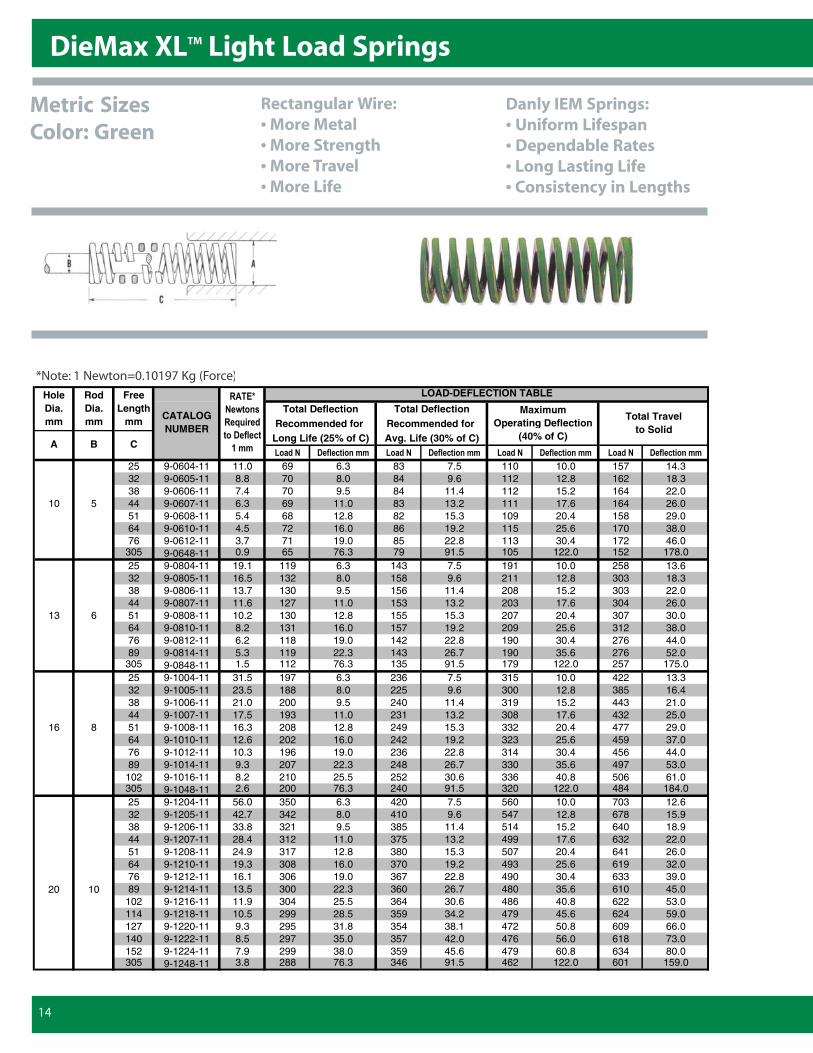
DieMax XLTM Light Load Springs
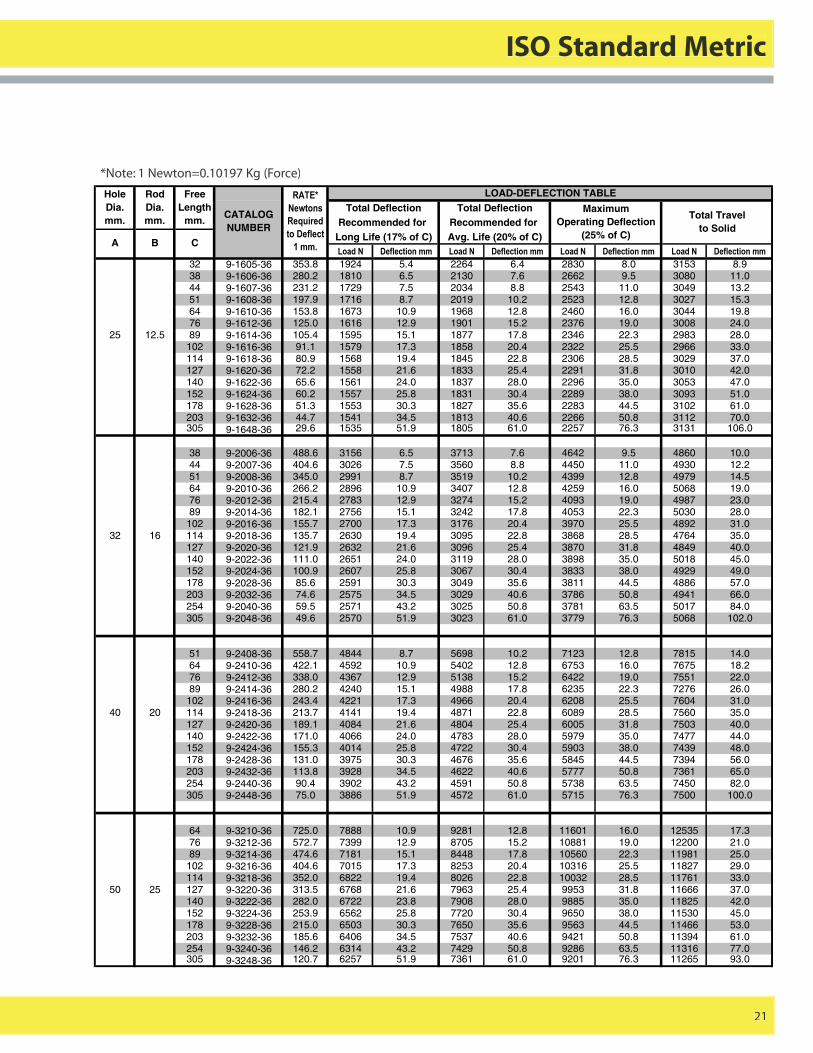
*Note: 1 Newton=0.10197 Kg (Force)
14
LOAD-DEFLECTION TABLE
Total Deflection Total DeflectionRecommended for Recommended for
Long Life (25% of C) Avg. Life (30% of C)������ ���� ������� ������ ���� ������� ������ ���� ������� ������ ���� �������
25 9-0604-11 11.0 69 6.3 83 7.5 110 10.0 157 14.332 9-0605-11 8.8 70 8.0 84 9.6 112 12.8 162 18.338 9-0606-11 7.4 70 9.5 84 11.4 112 15.2 164 22.0
10 5 44 9-0607-11 6.3 69 11.0 83 13.2 111 17.6 164 26.051 9-0608-11 5.4 68 12.8 82 15.3 109 20.4 158 29.064 9-0610-11 4.5 72 16.0 86 19.2 115 25.6 170 38.076 9-0612-11 3.7 71 19.0 85 22.8 113 30.4 172 46.0
305 9-0648-11 0.9 65 76.3 79 91.5 105 122.0 152 178.025 9-0804-11 19.1 119 6.3 143 7.5 191 10.0 258 13.632 9-0805-11 16.5 132 8.0 158 9.6 211 12.8 303 18.338 9-0806-11 13.7 130 9.5 156 11.4 208 15.2 303 22.044 9-0807-11 11.6 127 11.0 153 13.2 203 17.6 304 26.0
13 6 51 9-0808-11 10.2 130 12.8 155 15.3 207 20.4 307 30.064 9-0810-11 8.2 131 16.0 157 19.2 209 25.6 312 38.076 9-0812-11 6.2 118 19.0 142 22.8 190 30.4 276 44.089 9-0814-11 5.3 119 22.3 143 26.7 190 35.6 276 52.0
305 9-0848-11 1.5 112 76.3 135 91.5 179 122.0 257 175.025 9-1004-11 31.5 197 6.3 236 7.5 315 10.0 422 13.332 9-1005-11 23.5 188 8.0 225 9.6 300 12.8 385 16.438 9-1006-11 21.0 200 9.5 240 11.4 319 15.2 443 21.044 9-1007-11 17.5 193 11.0 231 13.2 308 17.6 432 25.0
16 8 51 9-1008-11 16.3 208 12.8 249 15.3 332 20.4 477 29.064 9-1010-11 12.6 202 16.0 242 19.2 323 25.6 459 37.076 9-1012-11 10.3 196 19.0 236 22.8 314 30.4 456 44.089 9-1014-11 9.3 207 22.3 248 26.7 330 35.6 497 53.0
102 9-1016-11 8.2 210 25.5 252 30.6 336 40.8 506 61.0305 9-1048-11 2.6 200 76.3 240 91.5 320 122.0 484 184.025 9-1204-11 56.0 350 6.3 420 7.5 560 10.0 703 12.632 9-1205-11 42.7 342 8.0 410 9.6 547 12.8 678 15.938 9-1206-11 33.8 321 9.5 385 11.4 514 15.2 640 18.944 9-1207-11 28.4 312 11.0 375 13.2 499 17.6 632 22.051 9-1208-11 24.9 317 12.8 380 15.3 507 20.4 641 26.064 9-1210-11 19.3 308 16.0 370 19.2 493 25.6 619 32.076 9-1212-11 16.1 306 19.0 367 22.8 490 30.4 633 39.0
20 10 89 9-1214-11 13.5 300 22.3 360 26.7 480 35.6 610 45.0102 9-1216-11 11.9 304 25.5 364 30.6 486 40.8 622 53.0114 9-1218-11 10.5 299 28.5 359 34.2 479 45.6 624 59.0127 9-1220-11 9.3 295 31.8 354 38.1 472 50.8 609 66.0140 9-1222-11 8.5 297 35.0 357 42.0 476 56.0 618 73.0152 9-1224-11 7.9 299 38.0 359 45.6 479 60.8 634 80.0305 9-1248-11 3.8 288 76.3 346 91.5 462 122.0 601 159.0
����%�
�&�����
���������
������� ��
!���
Maximum Operating Deflection
(40% of C)
Total Travel to Solid
A B C
Hole Dia. mm
RodDia. mm
Free Length
mm CATALOG NUMBER
Metric SizesColor: Green
Rectangular Wire:• More Metal• More Strength• More Travel• More Life
Danly IEM Springs:• Uniform Lifespan• Dependable Rates• Long Lasting Life• Consistency in Lengths
13216_Danly.P65 4/8/03, 1:53 PM14
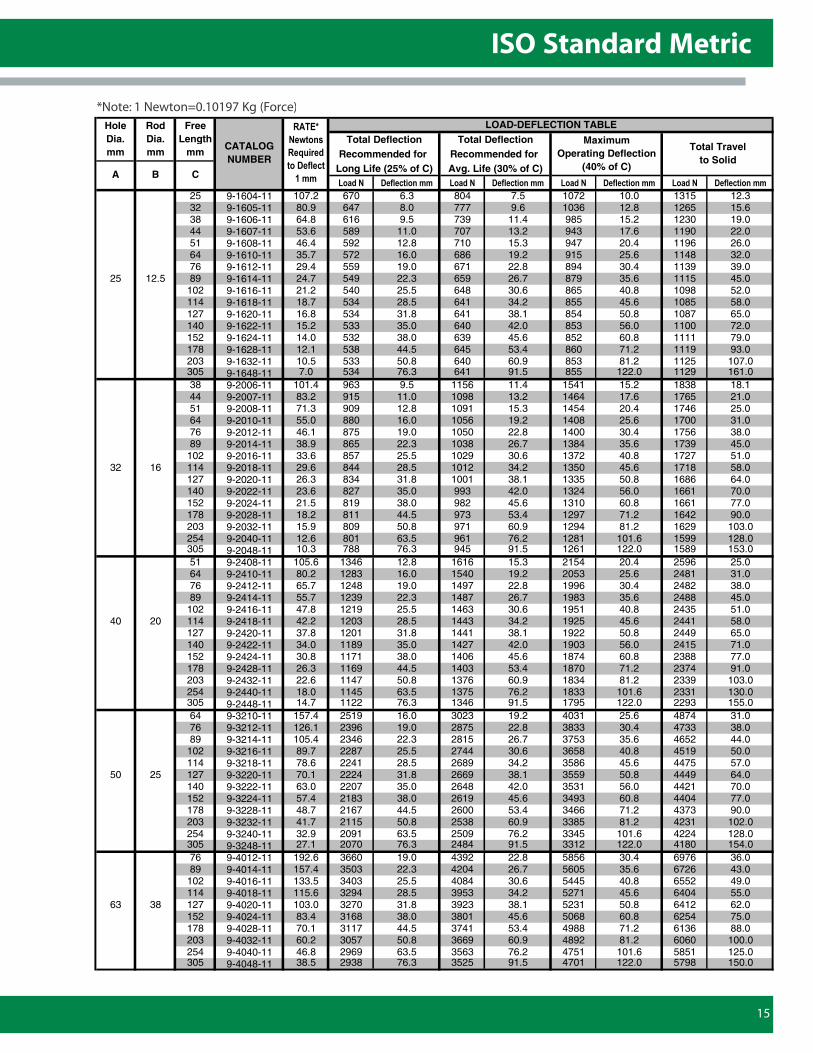
ISO Standard Metric
15
*Note: 1 Newton=0.10197 Kg (Force)LOAD-DEFLECTION TABLE
Total Deflection Total DeflectionRecommended for Recommended for
Long Life (25% of C) Avg. Life (30% of C)������ ���� ������� ������ ���� ������� ������ ���� ������� ������ ���� �������
25 9-1604-11 107.2 670 6.3 804 7.5 1072 10.0 1315 12.332 9-1605-11 80.9 647 8.0 777 9.6 1036 12.8 1265 15.638 9-1606-11 64.8 616 9.5 739 11.4 985 15.2 1230 19.044 9-1607-11 53.6 589 11.0 707 13.2 943 17.6 1190 22.051 9-1608-11 46.4 592 12.8 710 15.3 947 20.4 1196 26.064 9-1610-11 35.7 572 16.0 686 19.2 915 25.6 1148 32.076 9-1612-11 29.4 559 19.0 671 22.8 894 30.4 1139 39.0
25 12.5 89 9-1614-11 24.7 549 22.3 659 26.7 879 35.6 1115 45.0102 9-1616-11 21.2 540 25.5 648 30.6 865 40.8 1098 52.0114 9-1618-11 18.7 534 28.5 641 34.2 855 45.6 1085 58.0127 9-1620-11 16.8 534 31.8 641 38.1 854 50.8 1087 65.0140 9-1622-11 15.2 533 35.0 640 42.0 853 56.0 1100 72.0152 9-1624-11 14.0 532 38.0 639 45.6 852 60.8 1111 79.0178 9-1628-11 12.1 538 44.5 645 53.4 860 71.2 1119 93.0203 9-1632-11 10.5 533 50.8 640 60.9 853 81.2 1125 107.0305 9-1648-11 7.0 534 76.3 641 91.5 855 122.0 1129 161.038 9-2006-11 101.4 963 9.5 1156 11.4 1541 15.2 1838 18.144 9-2007-11 83.2 915 11.0 1098 13.2 1464 17.6 1765 21.051 9-2008-11 71.3 909 12.8 1091 15.3 1454 20.4 1746 25.064 9-2010-11 55.0 880 16.0 1056 19.2 1408 25.6 1700 31.076 9-2012-11 46.1 875 19.0 1050 22.8 1400 30.4 1756 38.089 9-2014-11 38.9 865 22.3 1038 26.7 1384 35.6 1739 45.0
102 9-2016-11 33.6 857 25.5 1029 30.6 1372 40.8 1727 51.032 16 114 9-2018-11 29.6 844 28.5 1012 34.2 1350 45.6 1718 58.0
127 9-2020-11 26.3 834 31.8 1001 38.1 1335 50.8 1686 64.0140 9-2022-11 23.6 827 35.0 993 42.0 1324 56.0 1661 70.0152 9-2024-11 21.5 819 38.0 982 45.6 1310 60.8 1661 77.0178 9-2028-11 18.2 811 44.5 973 53.4 1297 71.2 1642 90.0203 9-2032-11 15.9 809 50.8 971 60.9 1294 81.2 1629 103.0254 9-2040-11 12.6 801 63.5 961 76.2 1281 101.6 1599 128.0305 9-2048-11 10.3 788 76.3 945 91.5 1261 122.0 1589 153.051 9-2408-11 105.6 1346 12.8 1616 15.3 2154 20.4 2596 25.064 9-2410-11 80.2 1283 16.0 1540 19.2 2053 25.6 2481 31.076 9-2412-11 65.7 1248 19.0 1497 22.8 1996 30.4 2482 38.089 9-2414-11 55.7 1239 22.3 1487 26.7 1983 35.6 2488 45.0
102 9-2416-11 47.8 1219 25.5 1463 30.6 1951 40.8 2435 51.040 20 114 9-2418-11 42.2 1203 28.5 1443 34.2 1925 45.6 2441 58.0
127 9-2420-11 37.8 1201 31.8 1441 38.1 1922 50.8 2449 65.0140 9-2422-11 34.0 1189 35.0 1427 42.0 1903 56.0 2415 71.0152 9-2424-11 30.8 1171 38.0 1406 45.6 1874 60.8 2388 77.0178 9-2428-11 26.3 1169 44.5 1403 53.4 1870 71.2 2374 91.0203 9-2432-11 22.6 1147 50.8 1376 60.9 1834 81.2 2339 103.0254 9-2440-11 18.0 1145 63.5 1375 76.2 1833 101.6 2331 130.0305 9-2448-11 14.7 1122 76.3 1346 91.5 1795 122.0 2293 155.064 9-3210-11 157.4 2519 16.0 3023 19.2 4031 25.6 4874 31.076 9-3212-11 126.1 2396 19.0 2875 22.8 3833 30.4 4733 38.089 9-3214-11 105.4 2346 22.3 2815 26.7 3753 35.6 4652 44.0
102 9-3216-11 89.7 2287 25.5 2744 30.6 3658 40.8 4519 50.0114 9-3218-11 78.6 2241 28.5 2689 34.2 3586 45.6 4475 57.0
50 25 127 9-3220-11 70.1 2224 31.8 2669 38.1 3559 50.8 4449 64.0140 9-3222-11 63.0 2207 35.0 2648 42.0 3531 56.0 4421 70.0152 9-3224-11 57.4 2183 38.0 2619 45.6 3493 60.8 4404 77.0178 9-3228-11 48.7 2167 44.5 2600 53.4 3466 71.2 4373 90.0203 9-3232-11 41.7 2115 50.8 2538 60.9 3385 81.2 4231 102.0254 9-3240-11 32.9 2091 63.5 2509 76.2 3345 101.6 4224 128.0305 9-3248-11 27.1 2070 76.3 2484 91.5 3312 122.0 4180 154.076 9-4012-11 192.6 3660 19.0 4392 22.8 5856 30.4 6976 36.089 9-4014-11 157.4 3503 22.3 4204 26.7 5605 35.6 6726 43.0
102 9-4016-11 133.5 3403 25.5 4084 30.6 5445 40.8 6552 49.0114 9-4018-11 115.6 3294 28.5 3953 34.2 5271 45.6 6404 55.0
63 38 127 9-4020-11 103.0 3270 31.8 3923 38.1 5231 50.8 6412 62.0152 9-4024-11 83.4 3168 38.0 3801 45.6 5068 60.8 6254 75.0178 9-4028-11 70.1 3117 44.5 3741 53.4 4988 71.2 6136 88.0203 9-4032-11 60.2 3057 50.8 3669 60.9 4892 81.2 6060 100.0254 9-4040-11 46.8 2969 63.5 3563 76.2 4751 101.6 5851 125.0305 9-4048-11 38.5 2938 76.3 3525 91.5 4701 122.0 5798 150.0
����%�
�&�����
���������
������� ��
!���
Maximum Operating Deflection
(40% of C)
Total Travel to Solid
A B C
Hole Dia. mm
RodDia. mm
Free Length
mmCATALOG NUMBER
13216_Danly.P65 4/8/03, 1:53 PM15
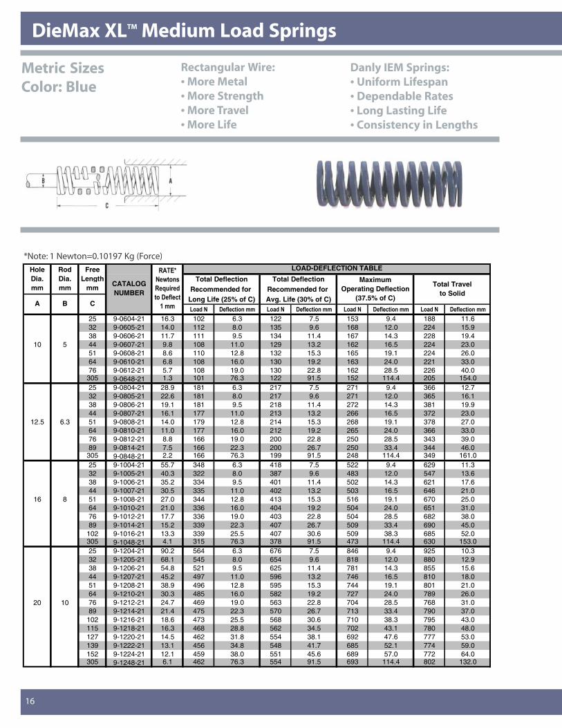
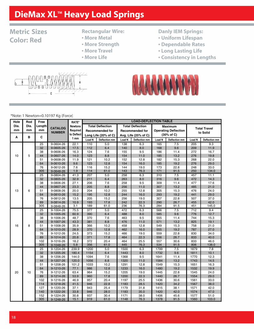
DieMax XLTM Medium Load SpringsDieMax XLTM Medium Load Springs
16
*Note: 1 Newton=0.10197 Kg (Force)LOAD-DEFLECTION TABLE
Total Deflection Total DeflectionRecommended for Recommended for
Long Life (25% of C) Avg. Life (30% of C)������ ���� ������� ������ ���� ������� ������ ���� ������� ������ ���� �������
25 9-0604-21 16.3 102 6.3 122 7.5 153 9.4 188 11.632 9-0605-21 14.0 112 8.0 135 9.6 168 12.0 224 15.938 9-0606-21 11.7 111 9.5 134 11.4 167 14.3 228 19.4
10 5 44 9-0607-21 9.8 108 11.0 129 13.2 162 16.5 224 23.051 9-0608-21 8.6 110 12.8 132 15.3 165 19.1 224 26.064 9-0610-21 6.8 108 16.0 130 19.2 163 24.0 221 33.076 9-0612-21 5.7 108 19.0 130 22.8 162 28.5 226 40.0
305 9-0648-21 1.3 101 76.3 122 91.5 152 114.4 205 154.025 9-0804-21 28.9 181 6.3 217 7.5 271 9.4 366 12.732 9-0805-21 22.6 181 8.0 217 9.6 271 12.0 365 16.138 9-0806-21 19.1 181 9.5 218 11.4 272 14.3 381 19.944 9-0807-21 16.1 177 11.0 213 13.2 266 16.5 372 23.0
12.5 6.3 51 9-0808-21 14.0 179 12.8 214 15.3 268 19.1 378 27.064 9-0810-21 11.0 177 16.0 212 19.2 265 24.0 366 33.076 9-0812-21 8.8 166 19.0 200 22.8 250 28.5 343 39.089 9-0814-21 7.5 166 22.3 200 26.7 250 33.4 344 46.0
305 9-0848-21 2.2 166 76.3 199 91.5 248 114.4 349 161.025 9-1004-21 55.7 348 6.3 418 7.5 522 9.4 629 11.332 9-1005-21 40.3 322 8.0 387 9.6 483 12.0 547 13.638 9-1006-21 35.2 334 9.5 401 11.4 502 14.3 621 17.644 9-1007-21 30.5 335 11.0 402 13.2 503 16.5 646 21.0
16 8 51 9-1008-21 27.0 344 12.8 413 15.3 516 19.1 670 25.064 9-1010-21 21.0 336 16.0 404 19.2 504 24.0 651 31.076 9-1012-21 17.7 336 19.0 403 22.8 504 28.5 682 38.089 9-1014-21 15.2 339 22.3 407 26.7 509 33.4 690 45.0
102 9-1016-21 13.3 339 25.5 407 30.6 509 38.3 685 52.0305 9-1048-21 4.1 315 76.3 378 91.5 473 114.4 630 153.025 9-1204-21 90.2 564 6.3 676 7.5 846 9.4 925 10.332 9-1205-21 68.1 545 8.0 654 9.6 818 12.0 880 12.938 9-1206-21 54.8 521 9.5 625 11.4 781 14.3 855 15.644 9-1207-21 45.2 497 11.0 596 13.2 746 16.5 810 18.051 9-1208-21 38.9 496 12.8 595 15.3 744 19.1 801 21.064 9-1210-21 30.3 485 16.0 582 19.2 727 24.0 789 26.0
20 10 76 9-1212-21 24.7 469 19.0 563 22.8 704 28.5 768 31.089 9-1214-21 21.4 475 22.3 570 26.7 713 33.4 790 37.0
102 9-1216-21 18.6 473 25.5 568 30.6 710 38.3 795 43.0115 9-1218-21 16.3 468 28.8 562 34.5 702 43.1 780 48.0127 9-1220-21 14.5 462 31.8 554 38.1 692 47.6 777 53.0139 9-1222-21 13.1 456 34.8 548 41.7 685 52.1 774 59.0152 9-1224-21 12.1 459 38.0 551 45.6 689 57.0 772 64.0305 9-1248-21 6.1 462 76.3 554 91.5 693 114.4 802 132.0
����%�
�&�����
���������
������� ��
!���
Maximum Operating Deflection
(37.5% of C)
Total Travel to Solid
A B C
Hole Dia. mm
RodDia. mm
Free Length
mm CATALOG NUMBER
Metric SizesColor: Blue
Rectangular Wire:• More Metal• More Strength• More Travel• More Life
Danly IEM Springs:• Uniform Lifespan• Dependable Rates• Long Lasting Life• Consistency in Lengths
13216_Danly.P65 4/8/03, 1:53 PM16
ISO Standard InchISO Standard Metric
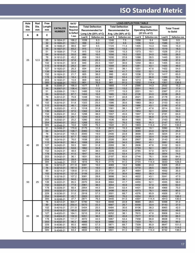
17
LOAD-DEFLECTION TABLETotal Deflection Total Deflection
Recommended for Recommended for Long Life (25% of C) Avg. Life (30% of C)������ ���� ������� ������ ���� ������� ������ ���� ������� ������ ���� �������
25 9-1604-21 166.2 1039 6.3 1246 7.5 1558 9.4 1649 9.932 9-1605-21 124.7 998 8.0 1197 9.6 1496 12.0 1586 12.738 9-1606-21 98.6 937 9.5 1124 11.4 1405 14.3 1505 15.344 9-1607-21 83.2 915 11.0 1098 13.2 1373 16.5 1519 18.351 9-1608-21 71.8 915 12.8 1099 15.3 1373 19.1 1528 21.064 9-1610-21 55.0 880 16.0 1056 19.2 1320 24.0 1455 26.076 9-1612-21 45.2 858 19.0 1030 22.8 1288 28.5 1445 32.0
25 12.5 89 9-1614-21 37.8 842 22.3 1010 26.7 1263 33.4 1408 37.0102 9-1616-21 32.9 840 25.5 1007 30.6 1259 38.3 1405 43.0115 9-1618-21 29.2 841 28.8 1009 34.5 1261 43.1 1425 49.0127 9-1620-21 26.3 834 31.8 1001 38.1 1251 47.6 1422 54.0139 9-1622-21 23.6 822 34.8 986 41.7 1232 52.1 1419 60.0152 9-1624-21 21.7 825 38.0 990 45.6 1238 57.0 1417 65.0178 9-1628-21 18.4 818 44.5 982 53.4 1227 66.8 1399 76.0203 9-1632-21 15.9 809 50.8 971 60.9 1213 76.1 1386 87.0305 9-1648-21 10.5 801 76.3 961 91.5 1202 114.4 1357 130.038 9-2006-21 166.0 1577 9.5 1893 11.4 2366 14.3 2532 15.244 9-2007-21 136.4 1501 11.0 1801 13.2 2251 16.5 2447 17.951 9-2008-21 116.1 1480 12.8 1777 15.3 2221 19.1 2397 21.064 9-2010-21 87.7 1404 16.0 1685 19.2 2106 24.0 2238 26.076 9-2012-21 70.9 1348 19.0 1617 22.8 2021 28.5 2178 31.089 9-2014-21 59.9 1333 22.3 1599 26.7 1999 33.4 2163 36.0
102 9-2016-21 51.8 1322 25.5 1586 30.6 1983 38.3 2153 42.032 16 115 9-2018-21 46.1 1324 28.8 1589 34.5 1986 43.1 2185 47.0
127 9-2020-21 41.5 1318 31.8 1581 38.1 1977 47.6 2214 53.0139 9-2022-21 37.5 1302 34.8 1563 41.7 1954 52.1 2202 59.0152 9-2024-21 34.2 1298 38.0 1557 45.6 1947 57.0 2191 64.0178 9-2028-21 29.1 1294 44.5 1552 53.4 1941 66.8 2175 75.0203 9-2032-21 25.2 1280 50.8 1536 60.9 1920 76.1 2163 86.0254 9-2040-21 20.0 1268 63.5 1521 76.2 1902 95.3 2147 107.0305 9-2048-21 16.6 1269 76.3 1522 91.5 1903 114.4 2151 130.051 9-2408-21 170.6 2175 12.8 2610 15.3 3262 19.1 3390 19.964 9-2410-21 128.7 2060 16.0 2471 19.2 3089 24.0 3210 25.076 9-2412-21 105.3 2000 19.0 2400 22.8 3000 28.5 3224 31.089 9-2414-21 87.7 1952 22.3 2343 26.7 2928 33.4 3129 36.0
102 9-2416-21 76.0 1938 25.5 2326 30.6 2907 38.3 3143 41.0115 9-2418-21 66.4 1908 28.8 2290 34.5 2862 43.1 3081 46.0
40 20 127 9-2420-21 59.5 1891 31.8 2269 38.1 2836 47.6 3102 52.0139 9-2422-21 53.6 1862 34.8 2235 41.7 2793 52.1 3057 57.0152 9-2424-21 48.9 1857 38.0 2228 45.6 2785 57.0 3072 63.0178 9-2428-21 41.5 1847 44.5 2216 53.4 2771 66.8 3054 74.0203 9-2432-21 36.1 1831 50.8 2197 60.9 2746 76.1 3038 84.0254 9-2440-21 28.9 1835 63.5 2202 76.2 2752 95.3 3083 107.0305 9-2448-21 23.8 1816 76.3 2179 91.5 2724 114.4 3033 128.064 9-3210-21 211.9 3391 16.0 4069 19.2 5086 24.0 5305 25.076 9-3212-21 167.4 3181 19.0 3817 22.8 4772 28.5 5024 30.089 9-3214-21 139.8 3110 22.3 3731 26.7 4664 33.4 4932 35.0
102 9-3216-21 121.9 3108 25.5 3730 30.6 4662 38.3 5042 41.0115 9-3218-21 107.2 3081 28.8 3698 34.5 4622 43.1 5041 47.0127 9-3220-21 94.6 3003 31.8 3603 38.1 4504 47.6 4914 52.0
50 25 139 9-3222-21 85.5 2970 34.8 3564 41.7 4455 52.1 4935 58.0152 9-3224-21 77.9 2961 38.0 3554 45.6 4442 57.0 4945 63.0178 9-3228-21 66.4 2954 44.5 3544 53.4 4431 66.8 4966 75.0203 9-3232-21 57.4 2915 50.8 3498 60.9 4373 76.1 4905 85.0229 9-3236-21 51.0 2918 57.3 3501 68.7 4376 85.9 4926 97.0254 9-3240-21 45.7 2903 63.5 3483 76.2 4354 95.3 4943 108.0305 9-3248-21 37.7 2871 76.3 3445 91.5 4307 114.4 4913 130.076 9-4012-21 304.7 5790 19.0 6948 22.8 8685 28.5 9398 31.089 9-4014-21 250.4 5572 22.3 6687 26.7 8358 33.4 9143 37.0
102 9-4016-21 211.9 5404 25.5 6484 30.6 8106 38.3 8965 42.0115 9-4018-21 185.6 5337 28.8 6405 34.5 8006 43.1 9032 49.0127 9-4020-21 164.1 5210 31.8 6252 38.1 7815 47.6 8908 54.0
63 38 152 9-4024-21 132.9 5051 38.0 6061 45.6 7577 57.0 8729 66.0178 9-4028-21 111.7 4972 44.5 5967 53.4 7458 66.8 8608 77.0203 9-4032-21 96.3 4888 50.8 5866 60.9 7333 76.1 8520 89.0229 9-4036-21 85.5 4893 57.3 5871 68.7 7339 85.9 8647 101.0254 9-4040-21 76.9 4882 63.5 5858 76.2 7323 95.3 8735 114.0305 9-4048-21 63.4 4834 76.3 5801 91.5 7251 114.4 8742 138.0
����%�
�&�����
���������
������� ��
!���
Maximum Operating Deflection
(37.5% of C)
Total Travel to Solid
A B C
Hole Dia. mm
RodDia. mm
Free Length
mmCATALOG NUMBER
13216_Danly.P65 4/8/03, 1:53 PM17
DieMax XLTM Heavy Load Springs
18
*Note: 1 Newton=0.10197 Kg (Force)LOAD-DEFLECTION TABLE
Total Deflection Total DeflectionRecommended for Recommended for
Long Life (20% of C) Avg. Life (25% of C)������ ���� ������� ������ ���� ������� ������ ���� ������� ������ ���� �������
25 9-0604-26 22.1 110 5.0 138 6.3 165 7.5 205 9.332 9-0605-26 17.5 112 6.4 140 8.0 168 9.6 209 11.938 9-0606-26 16.3 124 7.6 155 9.5 186 11.4 272 16.7
10 5 44 9-0607-26 14.0 123 8.8 154 11.0 185 13.2 276 19.851 9-0608-26 11.9 121 10.2 152 12.8 182 15.3 268 22.064 9-0610-26 9.6 123 12.8 154 16.0 185 19.2 276 29.076 9-0612-26 7.6 116 15.2 144 19.0 173 22.8 248 33.0
305 9-0648-26 1.9 114 61.0 143 76.3 171 91.5 250 134.025 9-0804-26 41.3 207 5.0 258 6.3 310 7.5 457 11.132 9-0805-26 32.9 211 6.4 263 8.0 316 9.6 472 14.338 9-0806-26 27.1 206 7.6 258 9.5 309 11.4 477 17.644 9-0807-26 23.3 205 8.8 256 11.0 307 13.2 485 21.0
13 6 51 9-0808-26 20.0 204 10.2 255 12.8 305 15.3 476 24.064 9-0810-26 15.2 195 12.8 244 16.0 293 19.2 441 29.076 9-0812-26 13.5 205 15.2 256 19.0 307 22.8 507 37.089 9-0814-26 10.9 193 17.8 242 22.3 290 26.7 455 42.0
305 9-0848-26 3.1 189 61.0 236 76.3 284 91.5 451 145.025 9-1004-26 75.5 377 5.0 472 6.3 566 7.5 712 9.432 9-1005-26 60.9 390 6.4 488 8.0 585 9.6 776 12.738 9-1006-26 48.7 370 7.6 463 9.5 555 11.4 744 15.344 9-1007-26 43.3 381 8.8 476 11.0 571 13.2 825 19.1
16 8 51 9-1008-26 35.9 366 10.2 458 12.8 549 15.3 758 21.064 9-1010-26 28.9 370 12.8 462 16.0 555 19.2 787 27.076 9-1012-26 24.5 373 15.2 466 19.0 559 22.8 830 34.089 9-1014-26 20.8 371 17.8 464 22.3 556 26.7 833 40.0
102 9-1016-26 18.2 372 20.4 464 25.5 557 30.6 833 46.0305 9-1048-26 5.8 356 61.0 445 76.3 534 91.5 806 138.025 9-1204-26 239.9 1200 5.0 1500 6.3 1799 7.5 1879 7.832 9-1205-26 180.4 1154 6.4 1443 8.0 1732 9.6 1811 10.138 9-1206-26 144.0 1094 7.6 1368 9.5 1641 11.4 1770 12.344 9-1207-26 120.0 1056 8.8 1320 11.0 1584 13.2 1743 14.551 9-1208-26 101.2 1033 10.2 1291 12.8 1549 15.3 1651 16.364 9-1210-26 77.1 986 12.8 1233 16.0 1480 19.2 1532 19.9
20 10 76 9-1212-26 63.4 964 15.2 1205 19.0 1445 22.8 1545 24.089 9-1214-26 53.9 960 17.8 1200 22.3 1440 26.7 1554 29.0
102 9-1216-26 46.9 957 20.4 1197 25.5 1436 30.6 1561 33.0114 9-1218-26 41.5 946 22.8 1183 28.5 1420 34.2 1567 38.0127 9-1220-26 37.1 943 25.4 1179 31.8 1415 38.1 1571 42.0140 9-1222-26 33.8 946 28.0 1183 35.0 1420 42.0 1574 47.0152 9-1224-26 30.8 937 30.4 1171 38.0 1406 45.6 1577 51.0305 9-1248-26 15.1 919 61.0 1148 76.3 1378 91.5 1560 103.0
����%�
�&�����
���������
������� ��
!���
Maximum Operating Deflection
(30% of C)
Total Travel to Solid
A B C
Hole Dia. mm
RodDia. mm
Free Length
mm CATALOG NUMBER
Metric SizesColor: Red
Rectangular Wire:• More Metal• More Strength• More Travel• More Life
Danly IEM Springs:• Uniform Lifespan• Dependable Rates• Long Lasting Life• Consistency in Lengths
13216_Danly.P65 4/8/03, 1:53 PM18
ISO Standard Metric
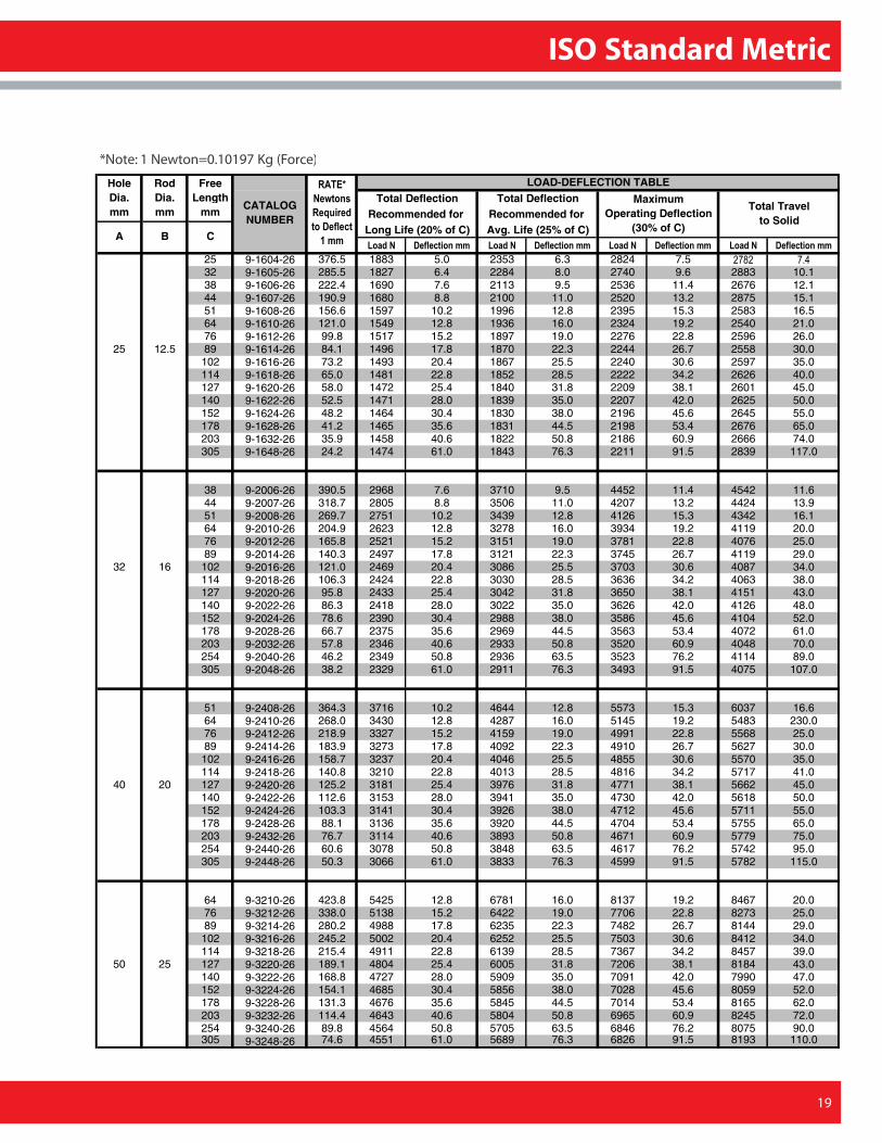
19
*Note: 1 Newton=0.10197 Kg (Force)
LOAD-DEFLECTION TABLETotal Deflection Total Deflection
Recommended for Recommended for Long Life (20% of C) Avg. Life (25% of C)������ ���� ������� ������ ���� ������� ������ ���� ������� ������ ���� �������
25 9-1604-26 376.5 1883 5.0 2353 6.3 2824 7.5 ���� ���
32 9-1605-26 285.5 1827 6.4 2284 8.0 2740 9.6 2883 10.138 9-1606-26 222.4 1690 7.6 2113 9.5 2536 11.4 2676 12.144 9-1607-26 190.9 1680 8.8 2100 11.0 2520 13.2 2875 15.151 9-1608-26 156.6 1597 10.2 1996 12.8 2395 15.3 2583 16.564 9-1610-26 121.0 1549 12.8 1936 16.0 2324 19.2 2540 21.076 9-1612-26 99.8 1517 15.2 1897 19.0 2276 22.8 2596 26.0
25 12.5 89 9-1614-26 84.1 1496 17.8 1870 22.3 2244 26.7 2558 30.0102 9-1616-26 73.2 1493 20.4 1867 25.5 2240 30.6 2597 35.0114 9-1618-26 65.0 1481 22.8 1852 28.5 2222 34.2 2626 40.0127 9-1620-26 58.0 1472 25.4 1840 31.8 2209 38.1 2601 45.0140 9-1622-26 52.5 1471 28.0 1839 35.0 2207 42.0 2625 50.0152 9-1624-26 48.2 1464 30.4 1830 38.0 2196 45.6 2645 55.0178 9-1628-26 41.2 1465 35.6 1831 44.5 2198 53.4 2676 65.0203 9-1632-26 35.9 1458 40.6 1822 50.8 2186 60.9 2666 74.0305 9-1648-26 24.2 1474 61.0 1843 76.3 2211 91.5 2839 117.0
38 9-2006-26 390.5 2968 7.6 3710 9.5 4452 11.4 4542 11.644 9-2007-26 318.7 2805 8.8 3506 11.0 4207 13.2 4424 13.951 9-2008-26 269.7 2751 10.2 3439 12.8 4126 15.3 4342 16.164 9-2010-26 204.9 2623 12.8 3278 16.0 3934 19.2 4119 20.076 9-2012-26 165.8 2521 15.2 3151 19.0 3781 22.8 4076 25.089 9-2014-26 140.3 2497 17.8 3121 22.3 3745 26.7 4119 29.0
32 16 102 9-2016-26 121.0 2469 20.4 3086 25.5 3703 30.6 4087 34.0114 9-2018-26 106.3 2424 22.8 3030 28.5 3636 34.2 4063 38.0127 9-2020-26 95.8 2433 25.4 3042 31.8 3650 38.1 4151 43.0140 9-2022-26 86.3 2418 28.0 3022 35.0 3626 42.0 4126 48.0152 9-2024-26 78.6 2390 30.4 2988 38.0 3586 45.6 4104 52.0178 9-2028-26 66.7 2375 35.6 2969 44.5 3563 53.4 4072 61.0203 9-2032-26 57.8 2346 40.6 2933 50.8 3520 60.9 4048 70.0254 9-2040-26 46.2 2349 50.8 2936 63.5 3523 76.2 4114 89.0305 9-2048-26 38.2 2329 61.0 2911 76.3 3493 91.5 4075 107.0
51 9-2408-26 364.3 3716 10.2 4644 12.8 5573 15.3 6037 16.664 9-2410-26 268.0 3430 12.8 4287 16.0 5145 19.2 5483 230.076 9-2412-26 218.9 3327 15.2 4159 19.0 4991 22.8 5568 25.089 9-2414-26 183.9 3273 17.8 4092 22.3 4910 26.7 5627 30.0102 9-2416-26 158.7 3237 20.4 4046 25.5 4855 30.6 5570 35.0114 9-2418-26 140.8 3210 22.8 4013 28.5 4816 34.2 5717 41.0
40 20 127 9-2420-26 125.2 3181 25.4 3976 31.8 4771 38.1 5662 45.0140 9-2422-26 112.6 3153 28.0 3941 35.0 4730 42.0 5618 50.0152 9-2424-26 103.3 3141 30.4 3926 38.0 4712 45.6 5711 55.0178 9-2428-26 88.1 3136 35.6 3920 44.5 4704 53.4 5755 65.0203 9-2432-26 76.7 3114 40.6 3893 50.8 4671 60.9 5779 75.0254 9-2440-26 60.6 3078 50.8 3848 63.5 4617 76.2 5742 95.0305 9-2448-26 50.3 3066 61.0 3833 76.3 4599 91.5 5782 115.0
64 9-3210-26 423.8 5425 12.8 6781 16.0 8137 19.2 8467 20.076 9-3212-26 338.0 5138 15.2 6422 19.0 7706 22.8 8273 25.089 9-3214-26 280.2 4988 17.8 6235 22.3 7482 26.7 8144 29.0102 9-3216-26 245.2 5002 20.4 6252 25.5 7503 30.6 8412 34.0114 9-3218-26 215.4 4911 22.8 6139 28.5 7367 34.2 8457 39.0
50 25 127 9-3220-26 189.1 4804 25.4 6005 31.8 7206 38.1 8184 43.0140 9-3222-26 168.8 4727 28.0 5909 35.0 7091 42.0 7990 47.0152 9-3224-26 154.1 4685 30.4 5856 38.0 7028 45.6 8059 52.0178 9-3228-26 131.3 4676 35.6 5845 44.5 7014 53.4 8165 62.0203 9-3232-26 114.4 4643 40.6 5804 50.8 6965 60.9 8245 72.0254 9-3240-26 89.8 4564 50.8 5705 63.5 6846 76.2 8075 90.0305 9-3248-26 74.6 4551 61.0 5689 76.3 6826 91.5 8193 110.0
����%�
�&�����
���������
������� ��
!���
Maximum Operating Deflection
(30% of C)
Total Travel to Solid
A B C
Hole Dia. mm
RodDia. mm
Free Length
mmCATALOG NUMBER
13216_Danly.P65 4/8/03, 1:53 PM19
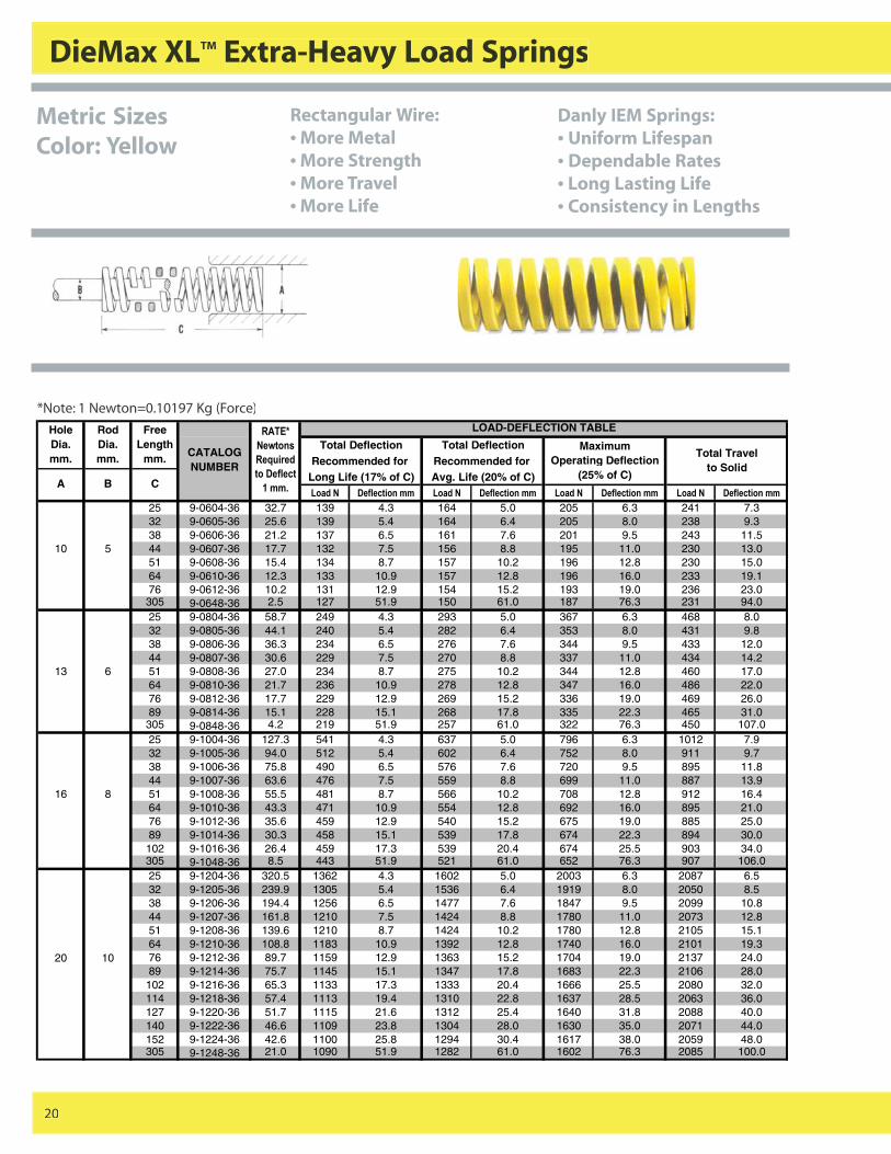
DieMax XLTM Extra-Heavy Load Springs
20
*Note: 1 Newton=0.10197 Kg (Force)LOAD-DEFLECTION TABLE
Total Deflection Total DeflectionRecommended for Recommended for
Long Life (17% of C) Avg. Life (20% of C)������ ���� ������� ������ ���� ������� ������ ���� ������� ������ ���� �������
25 9-0604-36 32.7 139 4.3 164 5.0 205 6.3 241 7.332 9-0605-36 25.6 139 5.4 164 6.4 205 8.0 238 9.338 9-0606-36 21.2 137 6.5 161 7.6 201 9.5 243 11.5
10 5 44 9-0607-36 17.7 132 7.5 156 8.8 195 11.0 230 13.051 9-0608-36 15.4 134 8.7 157 10.2 196 12.8 230 15.064 9-0610-36 12.3 133 10.9 157 12.8 196 16.0 233 19.176 9-0612-36 10.2 131 12.9 154 15.2 193 19.0 236 23.0305 9-0648-36 2.5 127 51.9 150 61.0 187 76.3 231 94.025 9-0804-36 58.7 249 4.3 293 5.0 367 6.3 468 8.032 9-0805-36 44.1 240 5.4 282 6.4 353 8.0 431 9.838 9-0806-36 36.3 234 6.5 276 7.6 344 9.5 433 12.044 9-0807-36 30.6 229 7.5 270 8.8 337 11.0 434 14.2
13 6 51 9-0808-36 27.0 234 8.7 275 10.2 344 12.8 460 17.064 9-0810-36 21.7 236 10.9 278 12.8 347 16.0 486 22.076 9-0812-36 17.7 229 12.9 269 15.2 336 19.0 469 26.089 9-0814-36 15.1 228 15.1 268 17.8 335 22.3 465 31.0305 9-0848-36 4.2 219 51.9 257 61.0 322 76.3 450 107.025 9-1004-36 127.3 541 4.3 637 5.0 796 6.3 1012 7.932 9-1005-36 94.0 512 5.4 602 6.4 752 8.0 911 9.738 9-1006-36 75.8 490 6.5 576 7.6 720 9.5 895 11.844 9-1007-36 63.6 476 7.5 559 8.8 699 11.0 887 13.9
16 8 51 9-1008-36 55.5 481 8.7 566 10.2 708 12.8 912 16.464 9-1010-36 43.3 471 10.9 554 12.8 692 16.0 895 21.076 9-1012-36 35.6 459 12.9 540 15.2 675 19.0 885 25.089 9-1014-36 30.3 458 15.1 539 17.8 674 22.3 894 30.0102 9-1016-36 26.4 459 17.3 539 20.4 674 25.5 903 34.0305 9-1048-36 8.5 443 51.9 521 61.0 652 76.3 907 106.025 9-1204-36 320.5 1362 4.3 1602 5.0 2003 6.3 2087 6.532 9-1205-36 239.9 1305 5.4 1536 6.4 1919 8.0 2050 8.538 9-1206-36 194.4 1256 6.5 1477 7.6 1847 9.5 2099 10.844 9-1207-36 161.8 1210 7.5 1424 8.8 1780 11.0 2073 12.851 9-1208-36 139.6 1210 8.7 1424 10.2 1780 12.8 2105 15.164 9-1210-36 108.8 1183 10.9 1392 12.8 1740 16.0 2101 19.3
20 10 76 9-1212-36 89.7 1159 12.9 1363 15.2 1704 19.0 2137 24.089 9-1214-36 75.7 1145 15.1 1347 17.8 1683 22.3 2106 28.0102 9-1216-36 65.3 1133 17.3 1333 20.4 1666 25.5 2080 32.0114 9-1218-36 57.4 1113 19.4 1310 22.8 1637 28.5 2063 36.0127 9-1220-36 51.7 1115 21.6 1312 25.4 1640 31.8 2088 40.0140 9-1222-36 46.6 1109 23.8 1304 28.0 1630 35.0 2071 44.0152 9-1224-36 42.6 1100 25.8 1294 30.4 1617 38.0 2059 48.0305 9-1248-36 21.0 1090 51.9 1282 61.0 1602 76.3 2085 100.0
����%�
�&�����
���������
������� ��
!���$
Maximum Operating Deflection
(25% of C)
Total Travel to Solid
A B C
Hole Dia. mm.
RodDia. mm.
Free Length
mm. CATALOG NUMBER
Metric SizesColor: Yellow
Rectangular Wire:• More Metal• More Strength• More Travel• More Life
Danly IEM Springs:• Uniform Lifespan• Dependable Rates• Long Lasting Life• Consistency in Lengths
13216_Danly.P65 4/8/03, 1:53 PM20
ISO Standard Metric
21
*Note: 1 Newton=0.10197 Kg (Force)
LOAD-DEFLECTION TABLETotal Deflection Total Deflection
Recommended for Recommended for Long Life (17% of C) Avg. Life (20% of C)������ ���� ������� ������ ���� ������� ������ ���� ������� ������ ���� �������
32 9-1605-36 353.8 1924 5.4 2264 6.4 2830 8.0 3153 8.938 9-1606-36 280.2 1810 6.5 2130 7.6 2662 9.5 3080 11.044 9-1607-36 231.2 1729 7.5 2034 8.8 2543 11.0 3049 13.251 9-1608-36 197.9 1716 8.7 2019 10.2 2523 12.8 3027 15.364 9-1610-36 153.8 1673 10.9 1968 12.8 2460 16.0 3044 19.876 9-1612-36 125.0 1616 12.9 1901 15.2 2376 19.0 3008 24.0
25 12.5 89 9-1614-36 105.4 1595 15.1 1877 17.8 2346 22.3 2983 28.0102 9-1616-36 91.1 1579 17.3 1858 20.4 2322 25.5 2966 33.0114 9-1618-36 80.9 1568 19.4 1845 22.8 2306 28.5 3029 37.0127 9-1620-36 72.2 1558 21.6 1833 25.4 2291 31.8 3010 42.0140 9-1622-36 65.6 1561 24.0 1837 28.0 2296 35.0 3053 47.0152 9-1624-36 60.2 1557 25.8 1831 30.4 2289 38.0 3093 51.0178 9-1628-36 51.3 1553 30.3 1827 35.6 2283 44.5 3102 61.0203 9-1632-36 44.7 1541 34.5 1813 40.6 2266 50.8 3112 70.0305 9-1648-36 29.6 1535 51.9 1805 61.0 2257 76.3 3131 106.0
38 9-2006-36 488.6 3156 6.5 3713 7.6 4642 9.5 4860 10.044 9-2007-36 404.6 3026 7.5 3560 8.8 4450 11.0 4930 12.251 9-2008-36 345.0 2991 8.7 3519 10.2 4399 12.8 4979 14.564 9-2010-36 266.2 2896 10.9 3407 12.8 4259 16.0 5068 19.076 9-2012-36 215.4 2783 12.9 3274 15.2 4093 19.0 4987 23.089 9-2014-36 182.1 2756 15.1 3242 17.8 4053 22.3 5030 28.0
102 9-2016-36 155.7 2700 17.3 3176 20.4 3970 25.5 4892 31.032 16 114 9-2018-36 135.7 2630 19.4 3095 22.8 3868 28.5 4764 35.0
127 9-2020-36 121.9 2632 21.6 3096 25.4 3870 31.8 4849 40.0140 9-2022-36 111.0 2651 24.0 3119 28.0 3898 35.0 5018 45.0152 9-2024-36 100.9 2607 25.8 3067 30.4 3833 38.0 4929 49.0178 9-2028-36 85.6 2591 30.3 3049 35.6 3811 44.5 4886 57.0203 9-2032-36 74.6 2575 34.5 3029 40.6 3786 50.8 4941 66.0254 9-2040-36 59.5 2571 43.2 3025 50.8 3781 63.5 5017 84.0305 9-2048-36 49.6 2570 51.9 3023 61.0 3779 76.3 5068 102.0
51 9-2408-36 558.7 4844 8.7 5698 10.2 7123 12.8 7815 14.064 9-2410-36 422.1 4592 10.9 5402 12.8 6753 16.0 7675 18.276 9-2412-36 338.0 4367 12.9 5138 15.2 6422 19.0 7551 22.089 9-2414-36 280.2 4240 15.1 4988 17.8 6235 22.3 7276 26.0
102 9-2416-36 243.4 4221 17.3 4966 20.4 6208 25.5 7604 31.040 20 114 9-2418-36 213.7 4141 19.4 4871 22.8 6089 28.5 7560 35.0
127 9-2420-36 189.1 4084 21.6 4804 25.4 6005 31.8 7503 40.0140 9-2422-36 171.0 4066 24.0 4783 28.0 5979 35.0 7477 44.0152 9-2424-36 155.3 4014 25.8 4722 30.4 5903 38.0 7439 48.0178 9-2428-36 131.0 3975 30.3 4676 35.6 5845 44.5 7394 56.0203 9-2432-36 113.8 3928 34.5 4622 40.6 5777 50.8 7361 65.0254 9-2440-36 90.4 3902 43.2 4591 50.8 5738 63.5 7450 82.0305 9-2448-36 75.0 3886 51.9 4572 61.0 5715 76.3 7500 100.0
64 9-3210-36 725.0 7888 10.9 9281 12.8 11601 16.0 12535 17.376 9-3212-36 572.7 7399 12.9 8705 15.2 10881 19.0 12200 21.089 9-3214-36 474.6 7181 15.1 8448 17.8 10560 22.3 11981 25.0
102 9-3216-36 404.6 7015 17.3 8253 20.4 10316 25.5 11827 29.0114 9-3218-36 352.0 6822 19.4 8026 22.8 10032 28.5 11761 33.0
50 25 127 9-3220-36 313.5 6768 21.6 7963 25.4 9953 31.8 11666 37.0140 9-3222-36 282.0 6722 23.8 7908 28.0 9885 35.0 11825 42.0152 9-3224-36 253.9 6562 25.8 7720 30.4 9650 38.0 11530 45.0178 9-3228-36 215.0 6503 30.3 7650 35.6 9563 44.5 11466 53.0203 9-3232-36 185.6 6406 34.5 7537 40.6 9421 50.8 11394 61.0254 9-3240-36 146.2 6314 43.2 7429 50.8 9286 63.5 11316 77.0305 9-3248-36 120.7 6257 51.9 7361 61.0 9201 76.3 11265 93.0
����%�
�&�����
���������
������� ��
!���$
Maximum Operating Deflection
(25% of C)
Total Travel to Solid
A B C
Hole Dia. mm.
RodDia. mm.
Free Length
mm.CATALOG NUMBER
13216_Danly.P65 4/8/03, 1:53 PM21
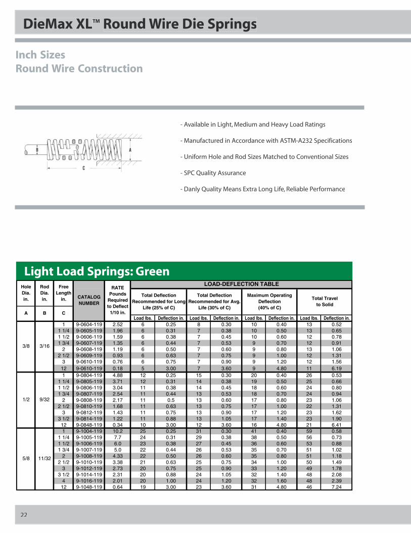
DieMax XLTM Round Wire Die Springs
Inch SizesRound Wire Construction
Light Load Springs: Green
- Available in Light, Medium and Heavy Load Ratings
- Manufactured in Accordance with ASTM-A232 Specifications
- Uniform Hole and Rod Sizes Matched to Conventional Sizes
- SPC Quality Assurance
- Danly Quality Means Extra Long Life, Reliable Performance
22
LOAD-DEFLECTION TABLE
��'���(�$ ���� �������$ ��'���(�$ ���� �������$ ��'���(�$ ���� �������$ ��'���(�$ ���� �������$
1 9-0604-119 2.52 6 0.25 8 0.30 10 0.40 13 0.521 1/4 9-0605-119 1.96 6 0.31 7 0.38 10 0.50 13 0.651 1/2 9-0606-119 1.59 6 0.38 7 0.45 10 0.60 12 0.781 3/4 9-0607-119 1.35 6 0.44 7 0.53 9 0.70 12 0.91
2 9-0608-119 1.19 6 0.50 7 0.60 9 0.80 13 1.062 1/2 9-0609-119 0.93 6 0.63 7 0.75 9 1.00 12 1.31
3 9-0610-119 0.76 6 0.75 7 0.90 9 1.20 12 1.5612 9-0610-119 0.18 5 3.00 7 3.60 9 4.80 11 6.191 9-0804-119 4.88 12 0.25 15 0.30 20 0.40 26 0.53
1 1/4 9-0805-119 3.71 12 0.31 14 0.38 19 0.50 25 0.661 1/2 9-0806-119 3.04 11 0.38 14 0.45 18 0.60 24 0.801 3/4 9-0807-119 2.54 11 0.44 13 0.53 18 0.70 24 0.94
2 9-0808-119 2.17 11 0.5 13 0.60 17 0.80 23 1.062 1/2 9-0810-119 1.68 11 0.63 13 0.75 17 1.00 22 1.31
3 9-0812-119 1.43 11 0.75 13 0.90 17 1.20 23 1.623 1/2 9-0814-119 1.22 11 0.88 13 1.05 17 1.40 23 1.9012 9-0848-119 0.34 10 3.00 12 3.60 16 4.80 21 6.411 9-1004-119 10.2 25 0.25 31 0.30 41 0.40 59 0.58
1 1/4 9-1005-119 7.7 24 0.31 29 0.38 38 0.50 56 0.731 1/2 9-1006-119 6.0 23 0.38 27 0.45 36 0.60 53 0.881 3/4 9-1007-119 5.0 22 0.44 26 0.53 35 0.70 51 1.02
2 9-1008-119 4.33 22 0.50 26 0.60 35 0.80 51 1.182 1/2 9-1010-119 3.38 21 0.63 25 0.75 34 1.00 50 1.49
3 9-1012-119 2.73 20 0.75 25 0.90 33 1.20 49 1.783 1/2 9-1014-119 2.31 20 0.88 24 1.05 32 1.40 48 2.08
4 9-1016-119 2.01 20 1.00 24 1.20 32 1.60 48 2.3912 9-1048-119 0.64 19 3.00 23 3.60 31 4.80 46 7.24
RATE Pounds
Required to Deflect
1/10 in.
Total Travel to Solid
Total Deflection Recommended for Long
Life (25% of C)
Total Deflection Recommended for Avg.
Life (30% of C)
Maximum Operating Deflection (40% of C)
CATALOG NUMBER
A B C
Hole Dia. in.
Rod Dia. in.
Free Length
in.
3/8 3/16
1/2 9/32
5/8 11/32
13216_Danly.P65 4/8/03, 1:53 PM22
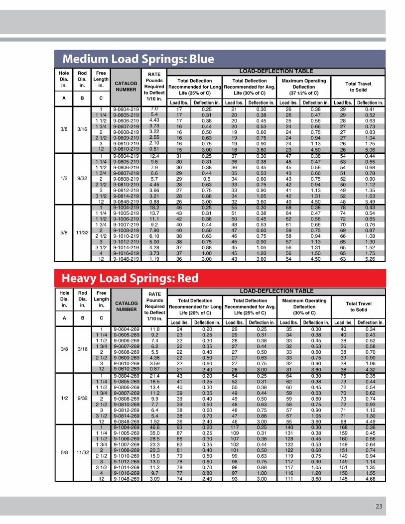
Medium Load Springs: Blue
Heavy Load Springs: Red
23
LOAD-DEFLECTION TABLE
��'���(�$ ���� �������$ ��'���(�$ ���� �������$ ��'���(�$ ���� �������$ ��'���(�$ ���� �������$
1 9-0604-219 7.0 17 0.25 21 0.30 26 0.38 29 0.411 1/4 9-0605-219 5.4 17 0.31 20 0.38 26 0.47 29 0.521 1/2 9-0606-219 4.43 17 0.38 20 0.45 25 0.56 28 0.631 3/4 9-0607-219 3.73 16 0.44 20 0.53 24 0.66 27 0.73
2 9-0608-219 3.22 16 0.50 19 0.60 24 0.75 27 0.832 1/2 9-0609-219 2.55 16 0.63 19 0.75 24 0.94 27 1.04
3 9-0610-219 2.10 16 0.75 19 0.90 24 1.13 26 1.2512 9-0610-219 0.51 15 3.00 18 3.60 23 4.50 26 5.061 9-0804-219 12.4 31 0.25 37 0.30 47 0.38 54 0.44
1 1/4 9-0805-219 9.6 30 0.31 36 0.38 45 0.47 53 0.551 1/2 9-0806-219 7.9 30 0.38 36 0.45 45 0.56 54 0.681 3/4 9-0807-219 6.6 29 0.44 35 0.53 43 0.66 51 0.78
2 9-0808-219 5.7 29 0.5 34 0.60 43 0.75 52 0.902 1/2 9-0810-219 4.45 28 0.63 33 0.75 42 0.94 50 1.12
3 9-0812-219 3.66 27 0.75 33 0.90 41 1.13 49 1.353 1/2 9-0814-219 3.21 28 0.88 34 1.05 42 1.31 52 1.6312 9-0848-219 0.88 26 3.00 32 3.60 40 4.50 48 5.491 9-1004-219 18.2 46 0.25 55 0.30 68 0.38 78 0.43
1 1/4 9-1005-219 13.7 43 0.31 51 0.38 64 0.47 74 0.541 1/2 9-1006-219 11.1 42 0.38 50 0.45 62 0.56 72 0.651 3/4 9-1007-219 9.2 40 0.44 48 0.53 61 0.66 70 0.76
2 9-1008-219 7.90 40 0.50 47 0.60 59 0.75 69 0.872 1/2 9-1010-219 6.10 38 0.63 46 0.75 58 0.94 66 1.08
3 9-1012-219 5.00 38 0.75 45 0.90 57 1.13 65 1.303 1/2 9-1014-219 4.28 37 0.88 45 1.05 56 1.31 65 1.52
4 9-1016-219 3.73 37 1.00 45 1.20 56 1.50 65 1.7512 9-1048-219 1.19 36 3.00 43 3.60 54 4.50 63 5.26
Hole Dia. in.
Rod Dia. in.
Free Length
in.
RATE Pounds
Required to Deflect
1/10 in.
Total Deflection Recommended for Long
Life (25% of C)
Total Deflection Recommended for Avg.
Life (30% of C)
Maximum Operating Deflection
(37 1/2% of C)
Total Travel to Solid
CATALOG NUMBER
A B C
3/8 3/16
1/2 9/32
5/8 11/32
LOAD-DEFLECTION TABLE
��'���(�$ ���� �������$ ��'���(�$ ���� �������$ ��'���(�$ ���� �������$ ��'���(�$ ���� �������$
1 9-0604-269 11.8 24 0.20 29 0.25 35 0.30 40 0.341 1/4 9-0605-269 9.2 23 0.25 29 0.31 34 0.38 40 0.431 1/2 9-0606-269 7.4 22 0.30 28 0.38 33 0.45 38 0.521 3/4 9-0607-269 6.2 22 0.35 27 0.44 32 0.53 36 0.58
2 9-0608-269 5.5 22 0.40 27 0.50 33 0.60 38 0.702 1/2 9-0609-269 4.38 22 0.50 27 0.63 33 0.75 39 0.90
3 9-0610-269 3.59 22 0.60 27 0.75 32 0.90 38 1.0612 9-0610-269 0.87 21 2.40 26 3.00 31 3.60 38 4.321 9-0804-269 21.4 43 0.20 54 0.25 64 0.30 75 0.35
1 1/4 9-0805-269 16.5 41 0.25 52 0.31 62 0.38 73 0.441 1/2 9-0806-269 13.4 40 0.30 50 0.38 60 0.45 72 0.541 3/4 9-0807-269 11.2 39 0.35 49 0.44 59 0.53 70 0.62
2 9-0808-269 9.9 39 0.40 49 0.50 59 0.60 73 0.742 1/2 9-0810-269 7.7 39 0.50 48 0.63 58 0.75 72 0.93
3 9-0812-269 6.4 38 0.60 48 0.75 57 0.90 71 1.123 1/2 9-0814-269 5.4 38 0.70 47 0.88 57 1.05 71 1.3012 9-0848-269 1.52 36 2.40 46 3.00 55 3.60 68 4.491 9-1004-269 46.6 93 0.20 117 0.25 140 0.30 168 0.36
1 1/4 9-1005-269 35.0 87 0.25 109 0.31 131 0.38 159 0.451 1/2 9-1006-269 28.5 86 0.30 107 0.38 128 0.45 160 0.561 3/4 9-1007-269 23.3 82 0.35 102 0.44 122 0.53 149 0.64
2 9-1008-269 20.3 81 0.40 101 0.50 122 0.60 151 0.742 1/2 9-1010-269 15.9 79 0.50 99 0.63 119 0.75 149 0.94
3 9-1012-269 13.0 78 0.60 98 0.75 117 0.90 149 1.143 1/2 9-1014-269 11.2 78 0.70 98 0.88 117 1.05 151 1.35
4 9-1016-269 9.7 77 0.80 97 1.00 116 1.20 150 1.5512 9-1048-269 3.09 74 2.40 93 3.00 111 3.60 145 4.68
Total Travel to Solid
A B C
Hole Dia. in.
Rod Dia. in.
Free Length
in.
RATE Pounds
Required to Deflect
1/10 in.
Total Deflection Recommended for Long
Life (20% of C)
Total Deflection Recommended for Avg.
Life (25% of C)
Maximum Operating Deflection (30% of C)
CATALOG NUMBER
5/8 11/32
3/8 3/16
1/2 9/32
13216_Danly.P65 4/8/03, 1:53 PM23
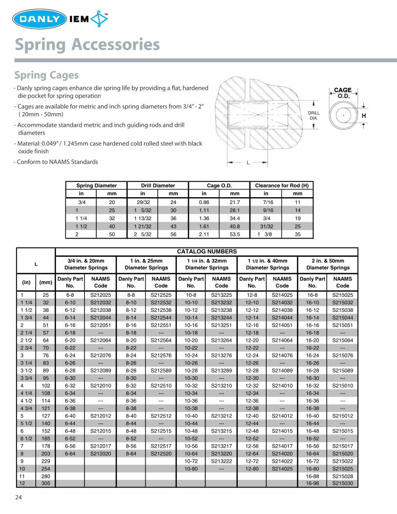
Spring Cages
24
Spring Accessories
- Danly spring cages enhance die spring life by providing a flat, hardened die pocket for spring operation
- Cages are available for metric and inch spring diameters from 3/4” - 2” ( 20mm - 50mm)
- Accommodate standard metric and inch guiding rods and drill diameters
- Material: 0.049” / 1.245mm case hardened cold rolled steel with black oxide finish
- Conform to NAAMS Standards
CATALOG NUMBERS
(in) (mm)Danly Part
No.NAAMS Code
Danly Part No.
NAAMS Code
Danly Part No.
NAAMS Code
Danly Part No.
NAAMS Code
Danly Part No.
NAAMS Code
1 25 6-8 S212025 8-8 S212525 10-8 S213225 12-8 S214025 16-8 S215025
1 1/4 32 6-10 S212032 8-10 S212532 10-10 S213232 12-10 S214032 16-10 S215032
1 1/2 38 6-12 S212038 8-12 S212538 10-12 S213238 12-12 S214038 16-12 S2150381 3/4 44 6-14 S212044 8-14 S212544 10-14 S213244 12-14 S214044 16-14 S215044
2 51 6-16 S212051 8-16 S212551 10-16 S213251 12-16 S214051 16-16 S215051
2 1/4 57 6-18 --- 8-18 --- 10-18 --- 12-18 --- 16-18 ---
2 1/2 64 6-20 S212064 8-20 S212564 10-20 S213264 12-20 S214064 16-20 S215064
2 3/4 70 6-22 --- 8-22 --- 10-22 --- 12-22 --- 16-22 ---
3 76 6-24 S212076 8-24 S212576 10-24 S213276 12-24 S214076 16-24 S215076
3 1/4 83 6-26 --- 8-26 --- 10-26 --- 12-26 --- 16-26 ---
3 1/2 89 6-28 S212089 8-28 S212589 10-28 S213289 12-28 S214089 16-28 S215089
3 3/4 95 6-30 --- 8-30 --- 10-30 --- 12-30 --- 16-30 ---
4 102 6-32 S212010 8-32 S212510 10-32 S213210 12-32 S214010 16-32 S215010
4 1/4 108 6-34 --- 8-34 --- 10-34 --- 12-34 --- 16-34 ---
4 1/2 114 6-36 --- 8-36 --- 10-36 --- 12-36 --- 16-36 ---
4 3/4 121 6-38 --- 8-38 --- 10-38 --- 12-38 --- 16-38 ---
5 127 6-40 S212012 8-40 S212512 10-40 S213212 12-40 S214012 16-40 S215012
5 1/2 140 6-44 --- 8-44 --- 10-44 --- 12-44 --- 16-44 ---6 152 6-48 S212015 8-48 S212515 10-48 S213215 12-48 S214015 16-48 S215015
6 1/2 165 6-52 --- 8-52 --- 10-52 --- 12-52 --- 16-52 ---
7 178 6-56 S212017 8-56 S212517 10-56 S213217 12-56 S214017 16-56 S215017
8 203 6-64 S212020 8-64 S212520 10-64 S213220 12-64 S214020 16-64 S215020
9 229 10-72 S213222 12-72 S214022 16-72 S215022
10 254 10-80 --- 12-80 S214025 16-80 S215025
11 280 16-88 S21502812 305 16-96 S215030
3/4 in. & 20mm Diameter Springs
L2 in. & 50mm
Diameter Springs1 in. & 25mm
Diameter Springs1 1/4 in. & 32mm
Diameter Springs1 1/2 in. & 40mm
Diameter Springs
Spring Diameter Drill Diameter Cage O.D. Clearance for Rod (H)
in mm in mm in mm in mm
3/4 20 29/32 24 0.86 21.7 7/16 11
1 25 1 5/32 30 1.11 28.1 9/16 14
1 1/4 32 1 13/32 36 1.36 34.4 3/4 19
1 1/2 40 1 21/32 43 1.61 40.8 31/32 25
2 50 2 5/32 56 2.11 53.5 1 3/8 35
13216_Danly.P65 4/8/03, 1:54 PM24
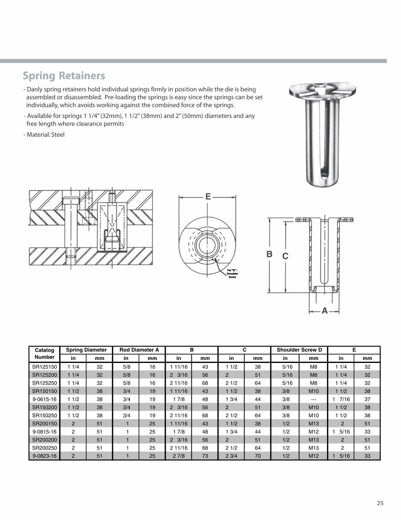
Spring Retainers
25
- Available for springs 1 1/4” (32mm), 1 1/2” (38mm) and 2” (50mm) diameters and any free length where clearance permits
- Material: Steel
- Danly spring retainers hold individual springs firmly in position while the die is being assembled or disassembled. Pre-loading the springs is easy since the springs can be set individually, which avoids working against the combined force of the springs.
in mm in mm in mm in mm in mm in mm
SR125150 1 1/4 32 5/8 16 1 11/16 43 1 1/2 38 5/16 M8 1 1/4 32
SR125200 1 1/4 32 5/8 16 2 3/16 56 2 51 5/16 M8 1 1/4 32
SR125250 1 1/4 32 5/8 16 2 11/16 68 2 1/2 64 5/16 M8 1 1/4 32
SR150150 1 1/2 38 3/4 19 1 11/16 43 1 1/2 38 3/8 M10 1 1/2 38
9-0615-16 1 1/2 38 3/4 19 1 7/8 48 1 3/4 44 3/8 --- 1 7/16 37
SR150200 1 1/2 38 3/4 19 2 3/16 56 2 51 3/8 M10 1 1/2 38
SR150250 1 1/2 38 3/4 19 2 11/16 68 2 1/2 64 3/8 M10 1 1/2 38
SR200150 2 51 1 25 1 11/16 43 1 1/2 38 1/2 M13 2 51
9-0815-16 2 51 1 25 1 7/8 48 1 3/4 44 1/2 M12 1 5/16 33
SR200200 2 51 1 25 2 3/16 56 2 51 1/2 M13 2 51
SR200250 2 51 1 25 2 11/16 68 2 1/2 64 1/2 M13 2 51
9-0823-16 2 51 1 25 2 7/8 73 2 3/4 70 1/2 M12 1 5/16 33
Shoulder Screw D ECatalog Number
Spring Diameter Rod Diameter A B C
13216_Danly.P65 4/8/03, 1:54 PM25
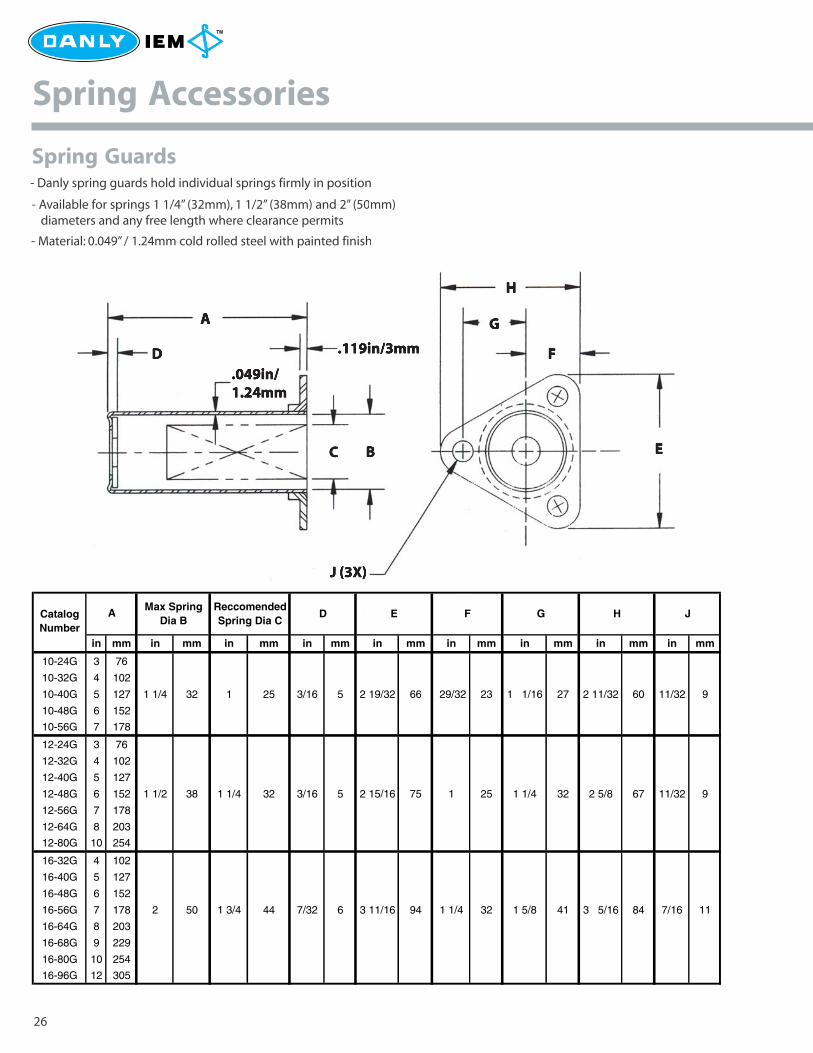
Spring Guards
26
Spring Accessories
- Danly spring guards hold individual springs firmly in position
- Available for springs 1 1/4” (32mm), 1 1/2” (38mm) and 2” (50mm) diameters and any free length where clearance permits
- Material: 0.049” / 1.24mm cold rolled steel with painted finish
Max Spring Dia B
Reccomended Spring Dia C
D E F G H J
in mm in mm in mm in mm in mm in mm in mm in mm in mm
10-24G 3 76
10-32G 4 102
10-40G 5 127 1 1/4 32 1 25 3/16 5 2 19/32 66 29/32 23 1 1/16 27 2 11/32 60 11/32 9
10-48G 6 152
10-56G 7 178
12-24G 3 76
12-32G 4 102
12-40G 5 127
12-48G 6 152 1 1/2 38 1 1/4 32 3/16 5 2 15/16 75 1 25 1 1/4 32 2 5/8 67 11/32 9
12-56G 7 178
12-64G 8 203
12-80G 10 254
16-32G 4 102
16-40G 5 127
16-48G 6 152
16-56G 7 178 2 50 1 3/4 44 7/32 6 3 11/16 94 1 1/4 32 1 5/8 41 3 5/16 84 7/16 11
16-64G 8 203
16-68G 9 229
16-80G 10 254
16-96G 12 305
ACatalog Number
13216_Danly.P65 4/8/03, 1:54 PM26
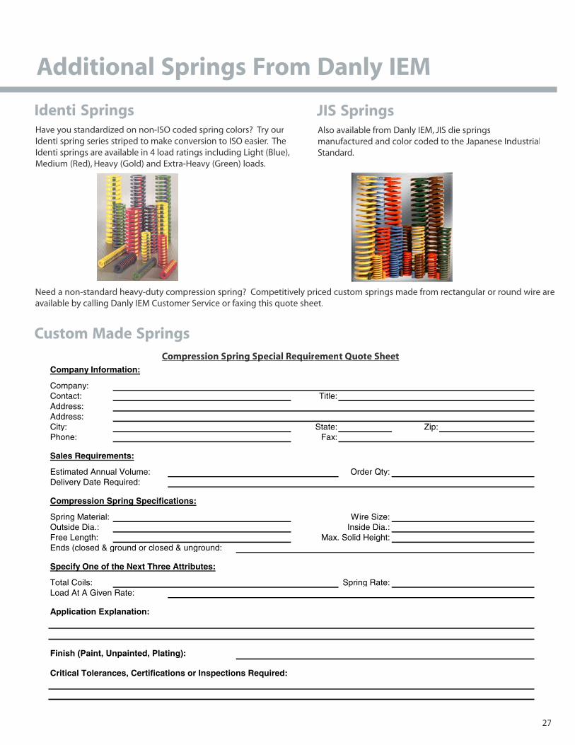
Identi Springs
27
Have you standardized on non-ISO coded spring colors? Try ourIdenti spring series striped to make conversion to ISO easier. TheIdenti springs are available in 4 load ratings including Light (Blue),Medium (Red), Heavy (Gold) and Extra-Heavy (Green) loads.
Additional Springs From Danly IEM
JIS SpringsAlso available from Danly IEM, JIS die springsmanufactured and color coded to the Japanese IndustrialStandard.
available by calling Danly IEM Customer Service or faxing this quote sheet.
Comprp ession Sprp ing Sg ppecial Requirq ement QQuote SheetCompany Information:
Company:Contact: Title:Address:Address:City: State: Zip:Phone: Fax:
Sales Requirements:
Estimated Annual Volume: Order Qty:Delivery Date Required:
Compression Spring Specifications:
Spring Material: Wire Size:Outside Dia.: Inside Dia.:Free Length: Max. Solid Height:Ends (closed & ground or closed & unground:
Specify One of the Next Three Attributes:
Total Coils: Spring Rate:Load At A Given Rate:
Application Explanation:
Finish (Paint, Unpainted, Plating):
Critical Tolerances, Certifications or Inspections Required:
Custom Made Springs
13216_Danly.P65 4/8/03, 1:54 PM27
Need a non-standard heavy-duty compression spring? Competitively priced custom springs made from rectangular or round wire are

Danly IEM6779 Engle Road, Suite ACleveland, OH 44130-7926
www.danly.com
CALL TOLL FREE1-800-243-2659FAX 1-800-833-2659
DS 116-2 4/03 © 2003 Danly IEMA Division of Connell Limited Partnership
All Rights Reserved
13216_Danly.P65 4/8/03, 1:54 PM28