1306256
TRANSCRIPT
7/28/2019 1306256
http://slidepdf.com/reader/full/1306256 1/5
120
1 1 . 1
0
D
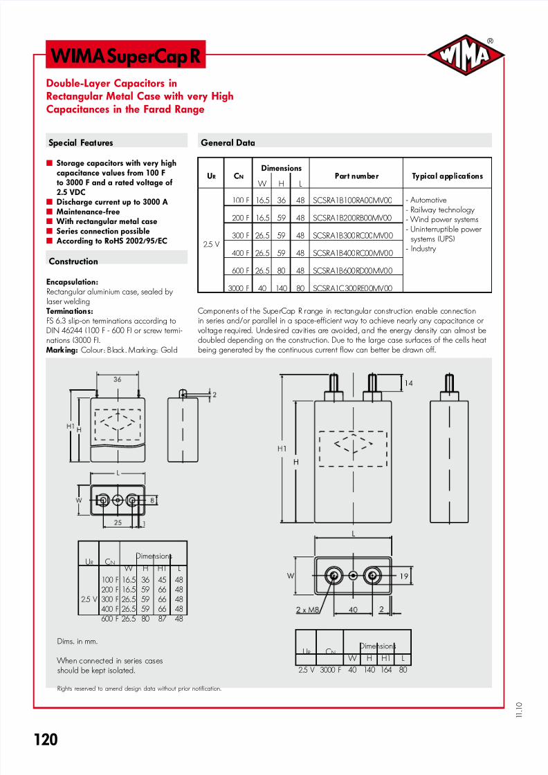
WIMA SuperCap RDouble-Layer Capacitors inRectangular Metal Case with very HighCapacitances in the Farad Range
Special Features General Data
˜ Storage capacitors with very highcapacitance values from 100 Fto 3000 F and a rated voltage of2.5 VDC
˜ Discharge current up to 3000 A˜ Maintenance-free˜ With rectangular metal case˜ Series connection possible˜ According to RoHS 2002/95/EC
Construction
Encapsulation:Rectangular aluminium case, sealed by laser welding
Termina tion s:FS 6.3 slip-on terminations according toDIN 46244 (100 F - 600 F) or screw termi-nations (3000 F).
Marking: Colour : B lack . Mark ing: Gold
UR CN
DimensionsPart number Typical applications
W H L
2.5 V
100 F 16.5 36 48 SCSRA1B100RA00MV00 - Automotive- Railway technology - Wind power systems- Uninterruptible power
systems (UPS)- Industry
200 F 16.5 59 48 SCSRA1B200RB00MV00
300 F 26.5 59 48 SCSRA1B300RC00MV00
400 F 26.5 59 48 SCSRA1B400RC00MV00
600 F 26.5 80 48 SCSRA1B600RD00MV00
3000 F 40 140 80 SCSRA1C300RE00MV00
Components o f t he SuperCap R range in rectangular construct ion enable connectionin series and/or parallel in a space-efficient way to achieve nearly any capacitance or
vol tage requi red. Undesired cav ities are avoided , and the energy dens ity can almost bedoubled depending on the construction. Due to the large case surfaces of the cells heat being generated by the continuous current flow can better be drawn off.
Dims. in mm.
When connected in ser ies casesshould be kept isolated.
Rights reserved to amend design data without prior notification.
UR CNDimensions
W H H1 L
2.5 V
100 F
200 F
300 F
400 F
600 F
16.516.5
26.5 26.5 26.5
36 59 59 5980
45 66 66 6687
48 48 48 48 48
UR CNDimensions
W H H1 L
2.5 V 3000 F 40 140 164 80

7/28/2019 1306256
http://slidepdf.com/reader/full/1306256 2/5
121
1 1 . 1
0
D
Continuation
WIMA SuperCap R
Technical Data
Capacitance: CN 100 F 200 F 300 F 400 F 600 F 3000 F
Capacitance tolerance: – ±20% ±20%
Rated voltage: UR 2.5 V 2.5 V
Rated current: I C 30 A 45 A 50 A 80 A 100 A 800 A
Pulse current: IP up to 200 A up to 350 A up to 400 A up to 600 A up to 800 A up to 3000 A
Internal resistance: R DC 12 m¸ 7 m¸ 6 m¸ 4 m¸ 3 m¸ 0.7 m¸
Max. stored energy: ±20% Emax. 0.313 kJ 0.625 kJ 0.938 kJ 1.25 k J 1.875 kJ 10 kJ
Oper atin g temperature : Top –30) C . . . +65) C –30) C . . . +65) C
Storage temp erature: Tst –40) C . . . +70) C –40) C . . . +70) C
Weight: m 40 g 62 g 90 g 95 g 120 g 615 g
Volume: V 0.028 l 0.047 l 0.075 l 0.075 l 0.1 l 0.45 l
Additional Data
Case: – Al 99.5 Al 99.5
Terminatio ns: – Brass slip-on terminations FS 6.3 Screw terminations M8 x 2
Comparative Data
Capacitance density:
gravimetric Cd 2500 F/kg 3200 F/kg 3400 F/kg 4300 F/kg 6400 F/kg 5300 F/kg
volumet ric C V 3600 F/l 4600 F/l 4400 F/l 5900 F/l 6660 F/l 7360 F /l
Energy density:
gravimetric Ed 2.2 Wh/kg 2.8 Wh/kg 3.0 Wh/kg 3.8 Wh/kg 4.5 Wh/kg 7.0 Wh/kg
volumet ric E V 3.2 Wh/l 3.7 Wh/l 4.0 Wh/l 5.4 Wh/l 6.0 Wh/l 6.3 Wh/l
7/28/2019 1306256
http://slidepdf.com/reader/full/1306256 3/5
110
1 1 . 1
0
D
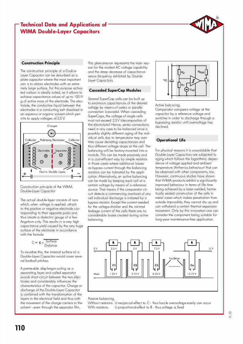
Construction Principle
The construct ion principle of a Double-Layer Capacitor can be described as aplate capacitor where the most important aim is to obtain electrodes with an extre-mely large surface. For this purpose activa-ted carbon is ideally suited, as it allows toachieve capacitance values of up to 100 F/g of active mass of the electrode. The elec-trolyte, the conductive liquid between theelectrodes is a conducting salt dissolved inan aqueous or organic solvent which per-mits to apply voltages of 2.5 V.
Cons truction princip le of the WIMA Double-Layer Capacitor
The actual doub le- laye r consis ts of ions which, when vol tage is appl ied, attachto the positive or negative electrode cor-responding to their opposite poles andthus create a dielectric gauge of a few
Angs trom only. This results i n a very highcapacitance yield caused by the very hugesurface of the electrode in accordance
with the formula
Surface C = e x
Distance
To visuali se this, the internal sur face o f aDouble-Layer Capacitor would cover seve-ral football pitches.
A permeable diaphragm acting as aseparating layer and called separator avoids short-circuit between the two elec-trodes and considerably influences thecharacteristics of the capacitor. Charge or discharge of the Double-Layer Capacitor is combined with the transformation of thelayers in the electrical field and thus withthe movement of the charge carriers in thesolvent - even through the separator film.
This phenomenon represents t he main rea-son for the modest AC voltage capability and the steep decrease of capacitance
versus frequency exhibited by Doub le-Layer Capacitors.
Cascaded SuperCap Modules
Several SuperCap cells can be built upto enormous capacitances of the desired
vol tage by means o f serie s or paralle lconnection (cascade). When cascadingSuperCaps, the voltage of single cells
must not exceed 2.5 V (decomposition ofthe electrolyte!) Hence, series connectionsneed in any case to be balanced since apossibly slightly different aging of the indi-
vidual cel ls due to temperature may over time cause deviating capacitances andthus different voltage drops at the cell. Thebalancing will be factory-mounted into amodule. This can be made passively andin a cost-efficient way by simple resistorsin those cases where additional lossesas bypass current through the balancingresistors can be tolerated by the appli-cation. Alternatively, an active balancing
can be made by keeping each cell at acertain voltage by means of a referencesource. That means if the comparator cir-cuit detects a commencing overload of any cell individual discharge is initiated by abypass resistor. Except the current needed
for the vol tage d ivid ier and the minimalleakage current of the cells there are noconsiderable losses created during activebalancing.
Act ive balancing. Comparator compares vol tage at thecapacitor by a reference voltage andswitches in order to discharge through abypassing resistor until overvoltage hasdeclined.
Operational Life
For physical reasons it is unavoidable that Double-Layer Capacitors are subjected toaging which follows the logarithmic depen-dence of voltage applied and ambient temperature (Arrhenius behaviour) that canbe observed with other components, too.However, continuous studies have shown
that WIMA products exhibit a significantly improved behaviour in terms of life timebeing achieved by a laser-welded, herme-tically sealed construction of the cells inmetal cases which makes penetration fromoutside impossible; they cannot dry up andcan withstand a certain thermal expansionmovement. Only by this innovation one canconsider the component being suitable for long-year maintenance-free application.
Passive balancing. Without r esis tor s: U reciprocal -ef fect to C - thus locale overvo ltage easi ly can occur With resistors: U p roport ional-e ffect to R - thus vol tage is fixed
Technical Data and Applications of WIMA Double-Layer Capacitors
7/28/2019 1306256
http://slidepdf.com/reader/full/1306256 4/5
1 1 . 1
0
111
D
Technical Data and Applications of WIMA Double-Layer Capacitors(Continuation)
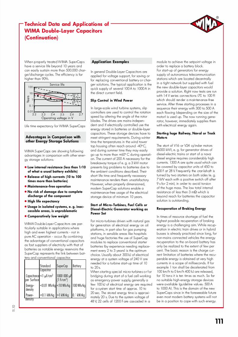
When p roperly treated WIMA SuperCapshave a service life beyond 10 years andcan easily sustain more than 500.000 char-ge/discharge cycles. The efficiency is far higher than 90%.
Life time expectancy for WIMA SuperCaps
Advantages in Compari son withother Energy Storage Solutions
WIMA SuperCaps are showing foIlowingadvantages in comparison with other ener-gy storage solutions:
” Low internal resistance (less than 1/10of what a usual battery exhibits)
” Release of high currents (10 to 100times more than batteries)
” Maintenance-free operation
” No risk of damage due to completedischarge of the component
” High life expectancy
” Usage in isolated systems, e. g. inac-cessible areas, is unproblematic
” Comparatively low weight
WIMA Double-Layer Capac itors are par-ticularly suitable in applications wherehigh and even highest currents - not in
pure AC operation - occur. By combiningthe advantage of conventional capacitorsas fast suppliers of electricity with that ofbatteries as notable energy reservoirs theSuperCap represents the link between bat-tery and conventional capacitor.
Standard SuperCap Battery Capacitor
Capacitance<1mF/cm2 1000000mFperSurface (1F/cm2)
Energy- <0.01Wh/kg<10Wh/kg 100Wh/kgdensity
Power- <0.1kW/kg >1kW/kg 0.1kW/kg density
Appl icat ion Examples
In general Double-Layer Capacitors areapplied for voltage support, for saving or
for replacing convent ional battery o r char-ger solutions. The typical application is thequick supply of several 100 A to 1000 A inthe direct current field.
Sli p Control in Wind Power
In large-scale wind turbine systems, slipcontrollers are used to control the rotation
speed by altering the angle of the rotor blades. The drives are mains-indepen-dent and if electrically controlled use theenergy stored in batteries or double-layer capacitors. These storage devices have tomeet stringent requirements. During winter time the temperatures in the wind tower top housing of ten reach around -40° C,and during summer time they may easily go up to more than +60° C during operati-on. The current of 200 A necessary for thebreakaway torque o f e. g. a 3 kW motor presents big problems to batteries due tothe ambient conditions described. Their
short life time and frequently necessary maintenance renders them unsatisfactory.However, when properly dimensioned,modern SuperCap solutions enable amaintenance-free usage of the electricalstorage device of minimum 10 years.
Start of Micro-Turbines, Fuel Cells orDiesel-Electric Generator working asPower Set
For micro-turbines driven with natural gas for generat ion of electr ical energy on oilplatforms, in part also for gas pumpingstations, in sensible areas like hospitalsand huge factories the use of SuperCapmodules to replace conventional starter batteries (by experience needing replace-ment every 2 to 3 years) is the optimumchoice. Usually about 300 kJ of electricalenergy at a system voltage of 240 V areneeded for a turbine start-up time of 10to 20 s.
When s tar ting special micro- turbines o r for bridging during start of a fuel cell workingas emergency power supply, generally a
few 100 kJ of electr ical energy are requ ired for a system start time of approx. 10 to 20 sec. The stored energy time i s approxi -mately 20 s. Due to the system voltage of
48 V, 22 cel ls of 1200 F are cascaded in a
module to achieve the setpoint voltage inorder to replace a battery block.For start-up of generators for energy supply of autonomous telecommunicationstations which are located decentrally in a tight network but supplied with fuelthe new double-layer capacitors wouldprovide a solution. Right now tests are run
with 14 V ser ies connections (70 to 100 F) which should render a maintenance-freeservice. After three starting processes in asequence their energy with 300 to 500 A each flowing (depending on the size of the
motor) is used up. The now running gene-rator, however, immediately supplies them with e lectrical energy again.
Startin g huge Rail way, Naval or Truck Moto rs
The start of V16 or V24 cyl inder motors(6000 kW), e. g. for generator drives ofdiesel-electric trains or start of a navaldiesel engine requires considerably highcurrents. 1300 A are quite usual which canbe covered by capacitor units of 450 to
600 F at 28 V. F requent ly the crankshaft isturned by two starters on both sides (e. g.7 kW each with a positive switch off after
9 s for 2 min), in order to avoid tor sionof the huge mass. The low total internalresistance of less then 3 m¸ which isbeyond reach for batteries the capacitor solution is outstanding.
Recuperation of Braking Energy
In times of resource shortage of fuel thehighest possible recuperation of brakingenergy is a challenging aim. While recup-eration in electric train drives or in hybridbusses is already practiced since long, for non-mains connected vehicles the energy recuperation to the on-board battery hasonly be realized to the extent of few per cent. The basic reason is the charge cur-rent limitation of batteries where the recu-perable energy is obtained at very highcurrents in a scope of milliseconds. If for example 1 ton shall be decelerated from100 km/h to 0 km/h 400 kJ are released,
for 10 tons i t is ten times as much. So far no suitable high-energy storage devices
were available (gu idel ine values: 500 A to 1000 A). This is the domain of the new SuperCaps since in the foreseeable futureeven most modern battery systems will not be in a position to cope with such energy.
7/28/2019 1306256
http://slidepdf.com/reader/full/1306256 5/5
125
1 1 . 1
0
D
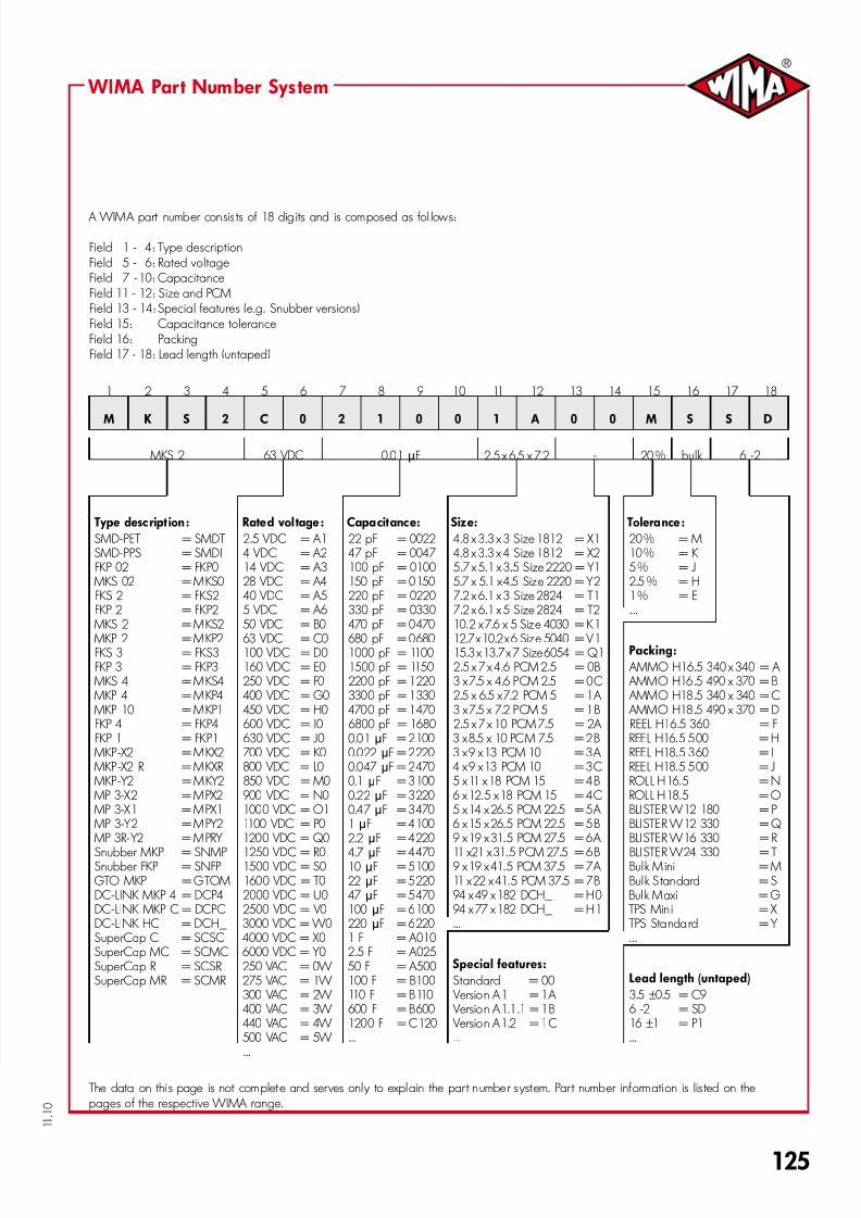
A WIMA part number consis ts of 18 dig its and is composed as fol lows:
Field 1 - 4: Type descriptionField 5 - 6: Rated voltageField 7 - 10: CapacitanceField 11 - 12: Size and PCMField 13 - 14: Special features (e.g. Snubber versions)Field 15: Capacitance toleranceField 16: PackingField 17 - 18: Lead length (untaped)
1 2 3 4 5 6 7 8 9 10 11 12 13 14 15 16 17 18
M K S 2 C 0 2 1 0 0 1 A 0 0 M S S D
MKS 2 63 VDC 0.01 mF 2.5 x 6.5 x 7.2 - 20 % bulk 6 -2
WIMA Part Number System
The data on this page is not complete and serves only to explain the part number s ystem. Par t number information is lis ted on thepages of the respective WIMA range.
Type descript ion: Rated voltage: Capacitance: Size: Tolerance:
SMD-PET = SMDT 2.5 VDC = A1 22 pF = 0022 4.8 x 3.3 x 3 Size 1812 = X1 20 % = MSMD-PPS = SMDI 4 VDC = A2 47 pF = 0047 4.8 x 3.3 x 4 Size 1812 = X2 10 % = K FKP 02 = FKP0 14 VDC = A3 100 pF = 0100 5.7 x 5.1 x 3.5 Size 2220 = Y1 5 % = J
MKS 02 = MKS0 28 VDC = A4 150 pF = 0150 5.7 x 5.1 x 4.5 Size 2220 = Y2 2.5 % = HFKS 2 = FKS2 40 VDC = A5 220 pF = 0220 7.2 x 6.1 x 3 Size 2824 = T1 1 % = EFKP 2 = FKP2 5 VDC = A6 330 pF = 0330 7.2 x 6.1 x 5 Size 2824 = T2 ...
MKS 2 = MKS2 50 VDC = B0 470 pF = 0470 10.2 x 7.6 x 5 Size 4030 = K1
MKP 2 = MKP2 63 VDC = C0 680 pF = 0680 12.7 x 10.2 x 6 Size 5040 = V1FKS 3 = FKS3 100 VDC = D0 1000 pF = 1100 15.3 x 13.7 x 7 Size 6054 = Q1 Packing:
FKP 3 = FKP3 160 VDC = E0 1500 pF = 1150 2.5 x 7 x 4.6 PCM 2.5 = 0B AMMO H16.5 340 x 340 = A MKS 4 = MKS4 250 VDC = F0 2200 pF = 1220 3 x 7.5 x 4.6 PCM 2.5 = 0C AMMO H16.5 490 x 370 = B MKP 4 = MKP4 400 VDC = G0 3300 pF = 1330 2.5 x 6.5 x 7.2 PCM 5 = 1A AMMO H18.5 340 x 340 = C MKP 10 = MKP1 450 VDC = H0 4700 pF = 1470 3 x 7.5 x 7.2 PCM 5 = 1B AMMO H18.5 490 x 370 = DFKP 4 = FKP4 600 VDC = I0 6800 pF = 1680 2.5 x 7 x 10 PCM 7.5 = 2A REEL H16.5 360 = F FKP 1 = FKP1 630 VDC = J0 0.01 mF = 2100 3 x 8.5 x 10 PCM 7.5 = 2B REEL H16.5 500 = H
MKP-X2 = MKX2 700 VDC = K0 0.022 mF = 2220 3 x 9 x 13 PCM 10 = 3A REEL H18.5 360 = I MKP-X2 R = MKXR 800 VDC = L0 0.047 mF = 2470 4 x 9 x 13 PCM 10 = 3C REEL H18.5 500 = J MKP-Y2 = MKY2 850 VDC = M0 0.1 mF = 3100 5 x 11 x 18 PCM 15 = 4B ROLL H16.5 = N MP 3-X2 = MPX2 900 VDC = N0 0.22 mF = 3220 6 x 12.5 x 18 PCM 15 = 4C ROLL H18.5 = O MP 3-X1 = MPX1 1000 VDC = O1 0.47 mF = 3470 5 x 14 x 26.5 PCM 22.5 = 5A BLISTER W12 180 = P MP 3-Y2 = MPY2 1100 VDC = P0 1 mF = 4100 6 x 15 x 26.5 PCM 22.5 = 5B BLISTER W12 330 = Q MP 3R-Y2 = MPRY 1200 VDC = Q0 2.2 mF = 4220 9 x 19 x 31.5 PCM 27.5 = 6A BLISTER W16 330 = R
Snubber MKP = SNMP 1250 VDC = R0 4.7 mF = 4470 11 x21 x 31.5 PCM 27.5 = 6B BLISTER W24 330 = TSnubber FKP = SNFP 1500 VDC = S0 10 mF = 5100 9 x 19 x 41.5 PCM 37.5 = 7A Bulk Mini = M
GTO MKP = GTOM 1600 VDC = T0 22 mF = 5220 11 x 22 x 41.5 PCM 37.5 = 7B Bulk S tandard = SDC-LINK MKP 4 = DCP4 2000 VDC = U0 47 mF = 5470 94 x 49 x 182 DCH_ = H0 Bulk Maxi = GDC-LINK MKP C = DCPC 2500 VDC = V0 100 mF = 6100 94 x 77 x 182 DCH_ = H1 TPS Mini = X DC-LINK HC = DCH_ 3000 VDC = W0 220 mF = 6220 ... TPS Standard = Y SuperCap C = SCSC 4000 VDC = X0 1 F = A010 ...SuperCap MC = SCMC 6000 VDC = Y0 2.5 F = A025SuperCap R = SCSR 250 VAC = 0W 50 F = A500 Special features:
SuperCap MR = SCMR 275 VAC = 1W 100 F = B100 Standard = 00 Lead length (untaped)
300 VAC = 2W 110 F = B110 Version A1 = 1A 3.5 ±0.5 = C9 400 VAC = 3W 600 F = B600 Version A1.1.1 = 1B 6 -2 = SD 440 VAC = 4W 1200 F = C120 Version A1.2 = 1C 16 ±1 = P1 500 VAC = 5W ... ... ......