13.012: hydrodynamics for ocean engineersweb.mit.edu/13.012/www/handouts/intro_to_hydro.pdfmit dept....
TRANSCRIPT
MIT Dept. Ocean Engineering, 2004
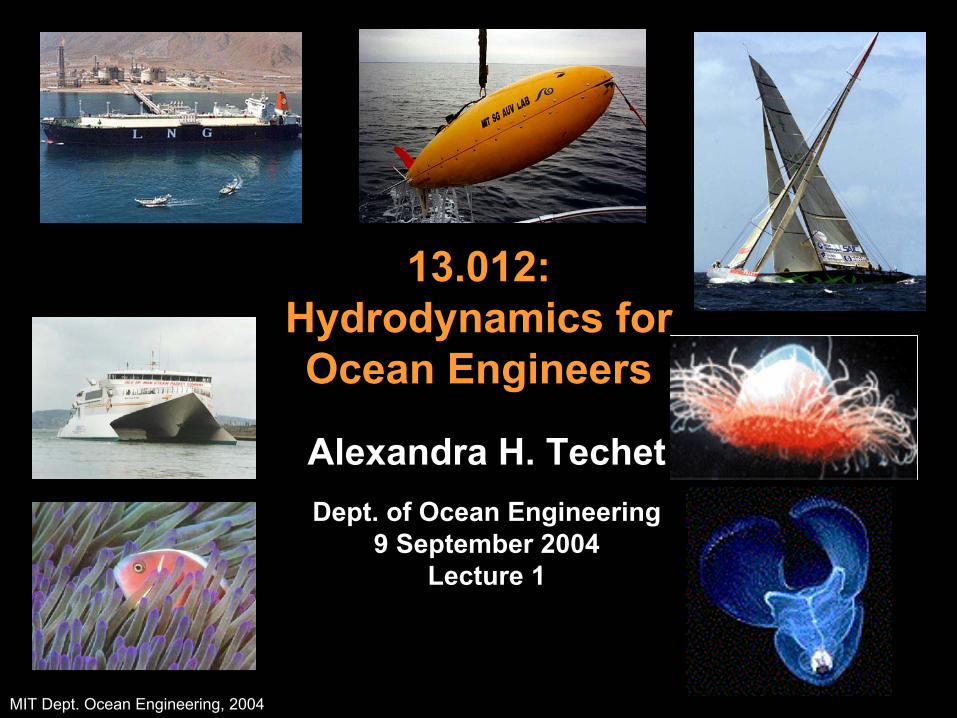
13.012: Hydrodynamics for Ocean Engineers
Alexandra H. TechetDept. of Ocean Engineering
9 September 2004Lecture 1
MIT Dept. Ocean Engineering, 2004
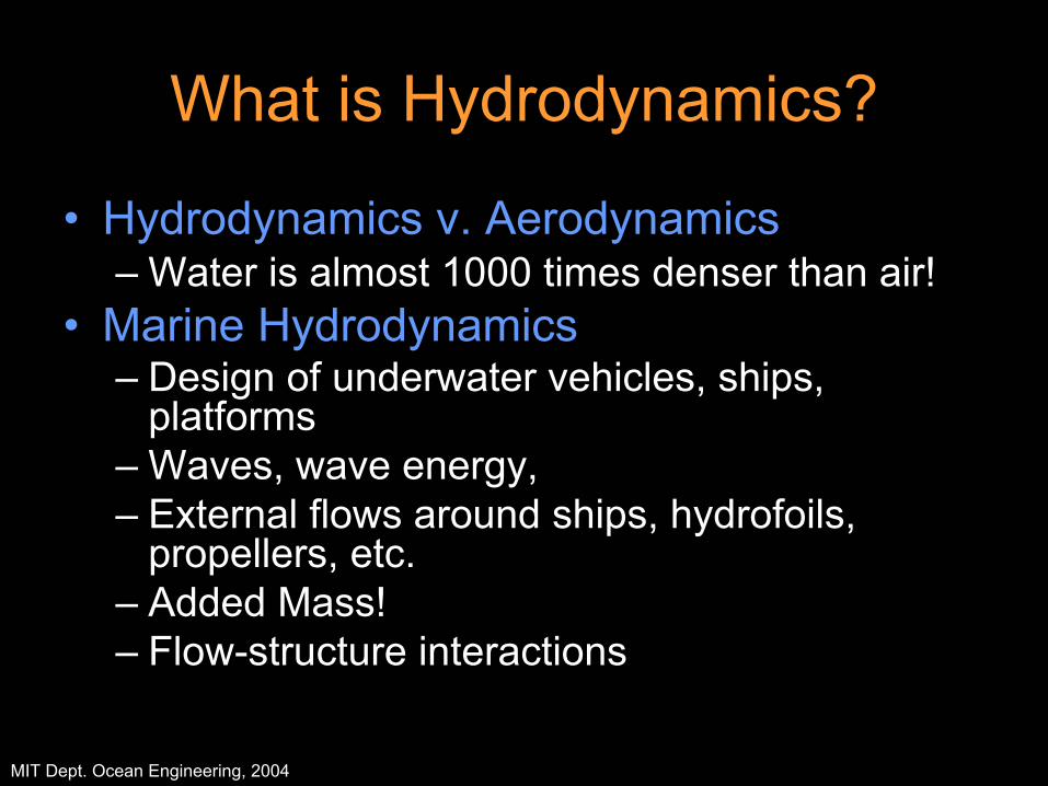
What is Hydrodynamics?
• Hydrodynamics v. Aerodynamics– Water is almost 1000 times denser than air!
• Marine Hydrodynamics– Design of underwater vehicles, ships,
platforms– Waves, wave energy, – External flows around ships, hydrofoils,
propellers, etc. – Added Mass!– Flow-structure interactions
MIT Dept. Ocean Engineering, 2004
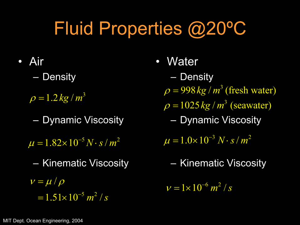
Fluid Properties @20ºC
• Air– Density
– Dynamic Viscosity
– Kinematic Viscosity
• Water– Density
– Dynamic Viscosity
– Kinematic Viscosity
3998 / (fresh water)kg mρ =31.2 /kg mρ =
5 2
/1.51 10 /m s
ν µ ρ−
=
= ×6 21 10 /m sν −= ×
5 21.82 10 /N s mµ −= × ⋅3 21.0 10 /N s mµ −= × ⋅
31025 / (seawater)kg mρ =

MIT Dept. Ocean Engineering, 2004
Ocean Exploration & Hydrodynamics
• 70-75% of the earth’s surface is covered by water.
• The earth’s oceans are one of our least explored resources.
• Many exciting discoveries lie waiting in the deep: such as Food, medicines, energy, and water.
• Good engineering is needed to advance current ocean exploration capabilities and to assure that our ocean resources will persist for generations to come.
• Understanding marine hydrodynamics can help us to design better ocean vessels and to understand physical ocean processes.
MIT Dept. Ocean Engineering, 2004
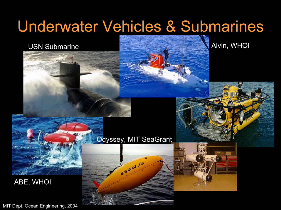
Underwater Vehicles & SubmarinesAlvin, WHOI
ABE, WHOI
Odyssey, MIT SeaGrant
USN Submarine
MIT Dept. Ocean Engineering, 2004
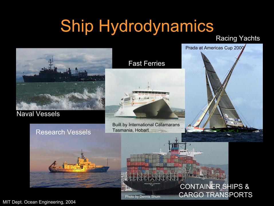
Ship Hydrodynamics
Photo by Dennis Shum
Built by International Catamarans Tasmania, Hobart
Prada at Americas Cup 2000
Fast Ferries
CONTAINER SHIPS & CARGO TRANSPORTS
Racing Yachts
Research Vessels
Naval Vessels

MIT Dept. Ocean Engineering, 2004
Offshore Engineering
Petrogras Rig Sinking off BrazilDue to explosion onboard
The Ursa unit is located approximately 130 miles south-east of New Orleans. ht
tp://
ww
w.o
ffsho
re-te
chno
logy
.com
/pro
ject
s/ur
sa/
The offshore platform must be designed to simutaneouslywithstand hurricane force waves and winds.

MIT Dept. Ocean Engineering, 2004
Genesis Spar Platform

MIT Dept. Ocean Engineering, 2004
Biologically Inspired Vehicles?!?
• The study of fish and other aquatic animals has led to engineering designs for underwater vehicles inspired by these creatures amazing ability to exist in the ocean.
• This mimicking of nature is widespread through science and engineering and is referred to as biomimetics…
MIT Dept. Ocean Engineering, 2004
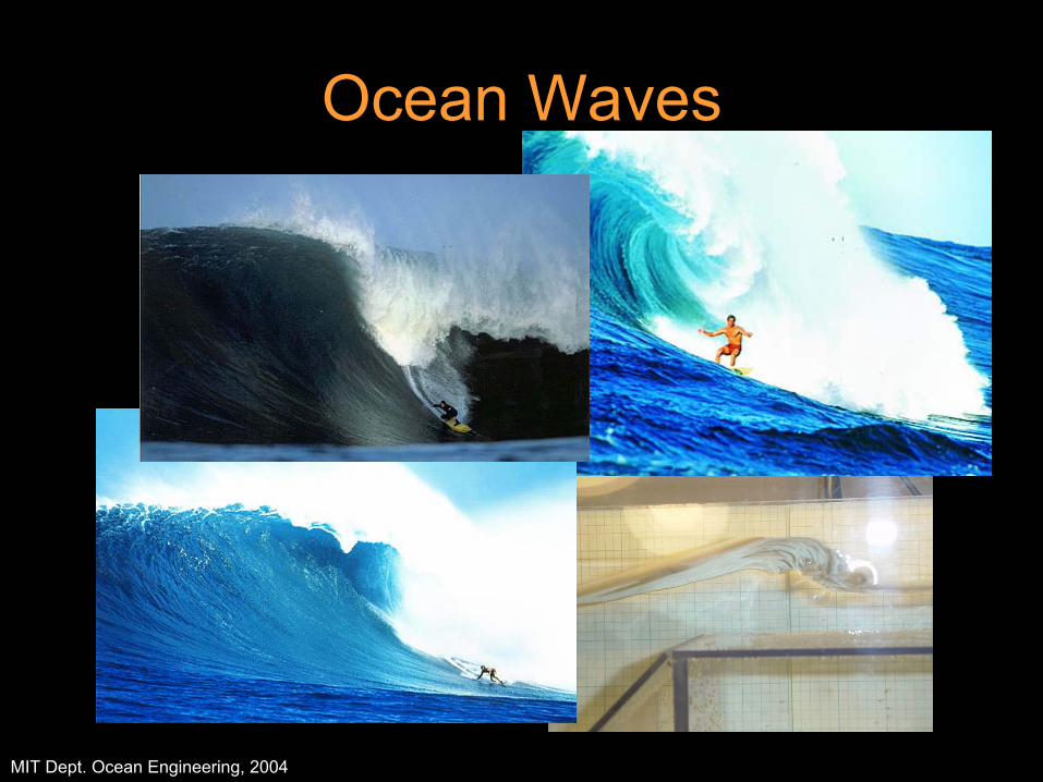
Ocean Waves
MIT Dept. Ocean Engineering, 2004
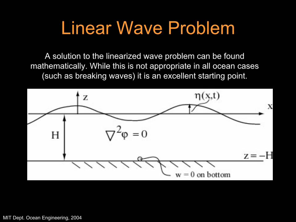
Linear Wave ProblemA solution to the linearized wave problem can be found
mathematically. While this is not appropriate in all ocean cases(such as breaking waves) it is an excellent starting point.
MIT Dept. Ocean Engineering, 2004
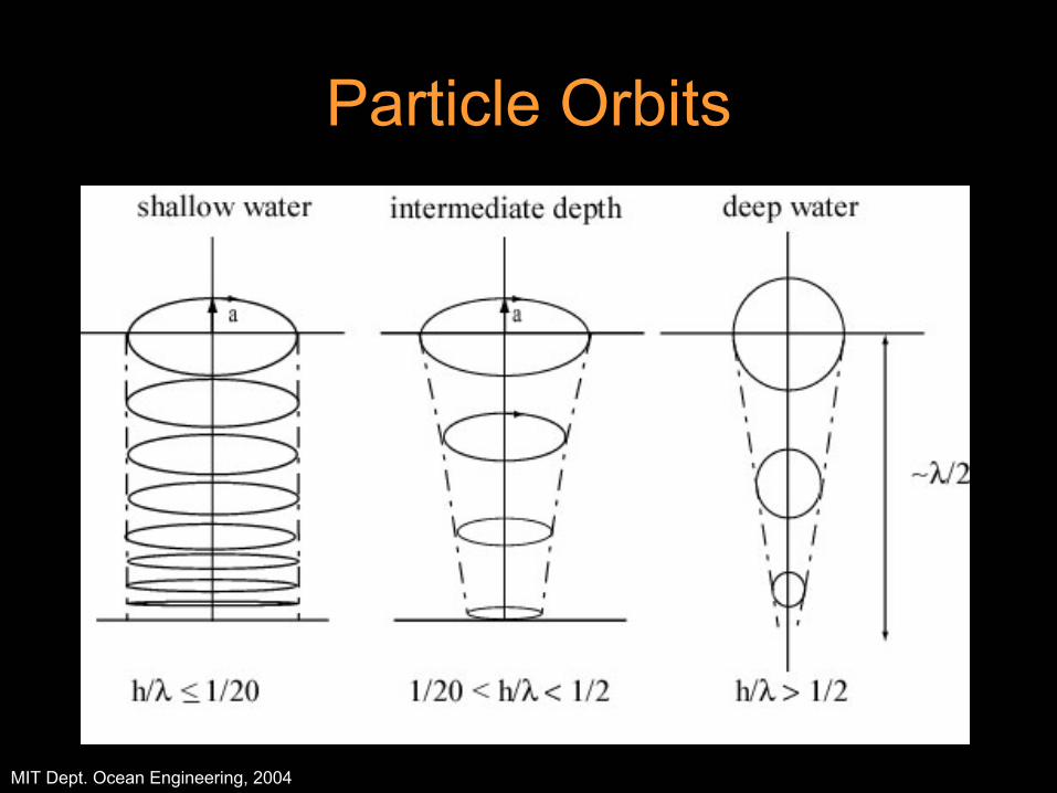
Particle Orbits
MIT Dept. Ocean Engineering, 2004
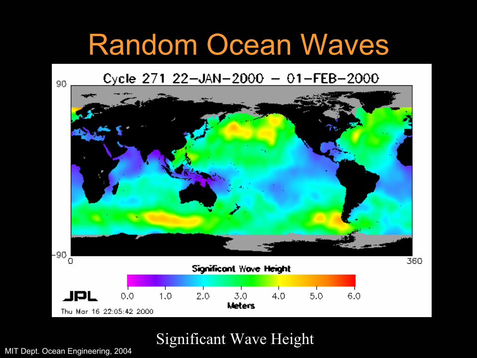
Random Ocean Waves
Significant Wave Height
MIT Dept. Ocean Engineering, 2004
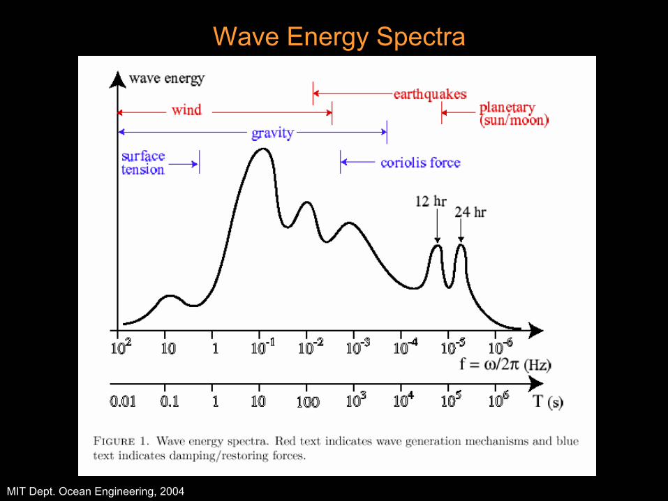
Wave Energy Spectra
MIT Dept. Ocean Engineering, 2004
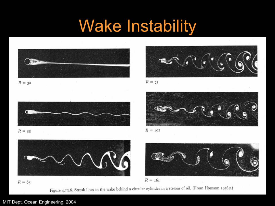
Wake Instability
MIT Dept. Ocean Engineering, 2004
Hydrodynamic Forces on Vessels
• Linear wave theory• Added mass!!!• Wave forces on bodies• Viscous forces on bodies:
– Skin Friction Drag– Vortex shedding, Vortex induced vibrations
• Viscous damping
MIT Dept. Ocean Engineering, 2004
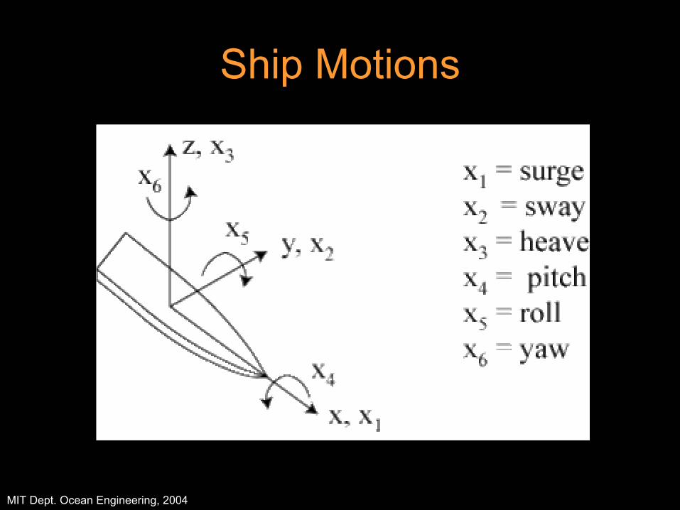
Ship Motions
MIT Dept. Ocean Engineering, 2004
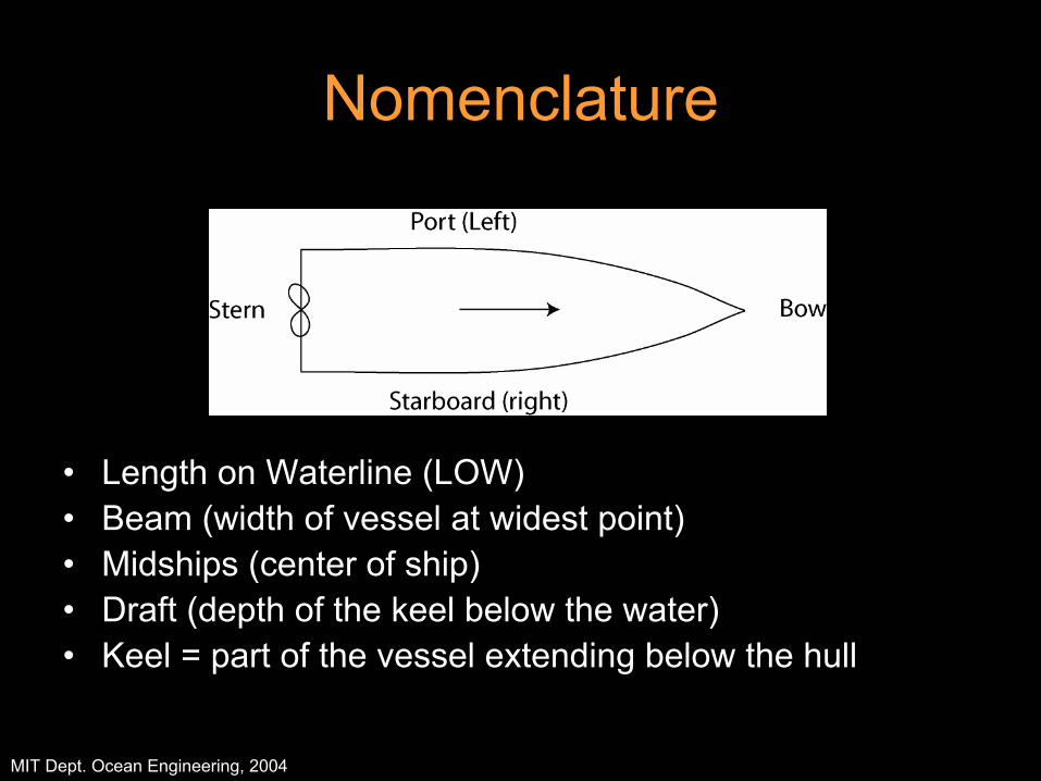
Nomenclature
• Length on Waterline (LOW)• Beam (width of vessel at widest point)• Midships (center of ship)• Draft (depth of the keel below the water)• Keel = part of the vessel extending below the hull
MIT Dept. Ocean Engineering, 2004
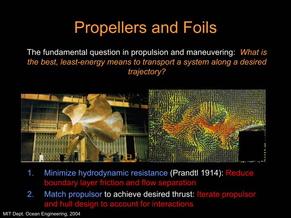
Propellers and Foils
1. Minimize hydrodynamic resistance (Prandtl 1914): Reduce boundary layer friction and flow separation
2. Match propulsor to achieve desired thrust: Iterate propulsor and hull design to account for interactions
0
5 0
1 0 0
1 stQtr
3 rdQtr
The fundamental question in propulsion and maneuvering: What is the best, least-energy means to transport a system along a desired
trajectory?
MIT Dept. Ocean Engineering, 2004
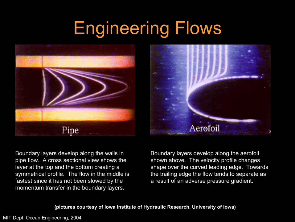
(pictures courtesy of Iowa Institute of Hydraulic Research, University of Iowa)
Boundary layers develop along the walls in pipe flow. A cross sectional view shows the layer at the top and the bottom creating a symmetrical profile. The flow in the middle is fastest since it has not been slowed by the momentum transfer in the boundary layers.
Boundary layers develop along the aerofoil shown above. The velocity profile changes shape over the curved leading edge. Towards the trailing edge the flow tends to separate as a result of an adverse pressure gradient.
Engineering Flows

MIT Dept. Ocean Engineering, 2004
This picture is a side view of the large eddies in a turbulent boundary layer. Laser-induced fluorescence is again used to capture the quasi-periodic coherent structures. Flow is from left to right.
Contributor: Prof. M. Gad-el-Hak, University of Notre Dame
Boundary Layers
MIT Dept. Ocean Engineering, 2004
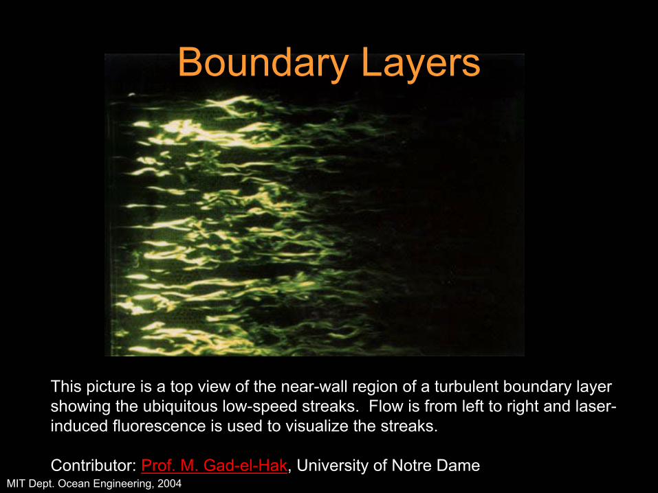
This picture is a top view of the near-wall region of a turbulent boundary layer showing the ubiquitous low-speed streaks. Flow is from left to right and laser-induced fluorescence is used to visualize the streaks.
Contributor: Prof. M. Gad-el-Hak, University of Notre Dame
Boundary Layers