1300.1 - hot insinsulation
TRANSCRIPT
8/12/2019 1300.1 - Hot Insinsulation
http://slidepdf.com/reader/full/13001-hot-insinsulation 1/49

8/12/2019 1300.1 - Hot Insinsulation
http://slidepdf.com/reader/full/13001-hot-insinsulation 2/49

8/12/2019 1300.1 - Hot Insinsulation
http://slidepdf.com/reader/full/13001-hot-insinsulation 3/49
8/12/2019 1300.1 - Hot Insinsulation
http://slidepdf.com/reader/full/13001-hot-insinsulation 4/49
PolarisEngineering
Standard
1300.1Rev.: 0Page: 4 of 49
HOT INSULATION
I. SCOPE
A. This Standard covers insulation requirements, materials and application methodsfor external insulation of vessels, equipment and piping in normal process plantatmospheres for operating temperatures from 140 oF to 1500 oF. This Standardexcludes storage tanks.
B. The insulation requirements described in this Standard are for the conservation ofheat, the protection of personnel from burns and process temperature control.
II. INSULATION REQUIREMENTS
A. Heat Conservation
1. Unless otherwise specified, process piping, utility piping, vessels andequipment shall be insulated for heat conservation when the processtemperature as defined by Paragraph II.E. is equal to or greater than140 oF. The insulation thickness shall be as specified by Section IX andthe developed Economic Thickness Table.
2. Piping, vessels and equipment, including valves, flanges and unions, shall be insulated for heat conservation when steam or electrically traced.
3. Vessel manways and heat exchanger flanges in operation above 200 oF
shall be insulated. Vessel manways and exchanger tube-sheet flangesshall be insulated after start-up operations and any required hot bolting orleak checks are completed. These operations may require the insulation to
be removed, the bolts retightened and the insulation replaced.
4. Piping and fittings which pass within 5 feet of the bottom-most tube of aircoolers and which operate at 200 oF and above shall be insulated inaccordance with the Economic Thickness Table.
5. Pumps and turbines in hot service shall be insulated unless otherwisespecified.
6. The word "fitting" shall designate ells, tees, caps, reducers, and stub-inconnections.
8/12/2019 1300.1 - Hot Insinsulation
http://slidepdf.com/reader/full/13001-hot-insinsulation 5/49
PolarisEngineering
Standard
1300.1Rev.: 0Page: 5 of 49
7. Flanges, flanged valve bodies and bonnets, and flanged fittings shallnormally be insulated in the following services only:
a. Steam-traced or externally heated lines
b. Steam linesc. Condensate lines (outdoors and in unheated areas)d. Lines insulated for personnel protectione. Lines that are in steam-out or in cycling servicef. Fireproofed lines
In other services they shall be left bare, unless otherwise specified in theProject Specification. When insulated, these items shall be considered
part of the piping and shall have the same insulation thicknessrequirements as the attached piping.
8. The following surfaces shall not be insulated for heat conservation:
a. Flanges, valves and unions unless heat traced or noted otherwiseon drawings, line schedules, or the Project Specifications.
b. Nameplates, code plates and stamping.
c. Expansion and rotation joints, slide valves and other moving parts.
d. Steam condensate lines that are vented to atmosphere, steam trapsand drains.
e. Steam service lines such as snuffing steam lines, steam-out branches to vessels, etc., which are in infrequent service andnormally cold. Such lines shall be insulated from the main headerto the first block valve.
f. Surfaces where heat loss is beneficial.
g. Refractory lined vessels and piping unless otherwise specified.
h. Vessels, which contain a catalyst and are normally cold, but areheated for short periods during catalyst removal, unless specifiedon the vessel outline drawing.
i. Shell and tube exchanger nozzle necks, double pipe hairpinexchanger shell nozzles, tube unions, tube connectors and shellconnectors.
j. Flanges where Figure 8 blinds are located, unless in moltenservices.
8/12/2019 1300.1 - Hot Insinsulation
http://slidepdf.com/reader/full/13001-hot-insinsulation 6/49
PolarisEngineering
Standard
1300.1Rev.: 0Page: 6 of 49
9. Handholes, sample connections, nozzles with blind flanges, etc., shall beinsulated, unless otherwise specified.
B. Personnel Protection
1. Unless otherwise specified, piping, vessel and equipment surfaces thatoperate above 140 oF and may be contacted by personnel during normalduties shall be insulated to maintain an outside surface temperature of notmore than 140 oF. The required insulation thickness shall be developed bythe Contractor. (See Section IX of this Standard.)
2. The insulation for personnel protection shall extend 7 feet above and 3 feet beyond walkways, platforms and other general access areas. Where gapsin insulation less than 10 feet would exist, the insulation shall runcontinuously.
3. Valve bodies shall have personnel protection insulation when there is a potential burn hazard, as outlined in Section II.B.2 above.
4. Hot pump cases, coolers, condensers, exchanger flanges and pipingflanges shall not be insulated for personnel protection; however, if uponfield inspection a possible hazard is evident, then shields, guard rails orother means of personnel protection shall be provided.
C. Process Stability
1. Insulation shall be required for piping, vessels and equipment where process temperature control is required. The extent of insulationrequirements shall be as noted on the piping isometrics, piping line list,
piping and instrument diagrams and/or insulation schedule.
2. Flanges and valve bodies in process lines where heat loss would have acritical effect on the operation shall be insulated when required by theProject Specifications. These requirements will be shown on the pipingisometrics, piping and instrument diagrams, pipe line list and/or insulationschedule.
D. Documentation of Specific Insulation Requirements
Specific piping to be insulated will be noted on the piping isometrics, the pipe linelist, piping and instrument diagrams and/or insulation schedule. Vessels andexchangers to be insulated will be shown on vessel and exchanger outlinedrawings and/or piping and instrument diagrams. Pumps, turbines and irregularshapes to be insulated will be shown on the equipment list, piping and/orinstrument diagrams. Other equipment to be insulated will be listed on aequipment paint, insulation and lining schedule.

8/12/2019 1300.1 - Hot Insinsulation
http://slidepdf.com/reader/full/13001-hot-insinsulation 7/49
PolarisEngineering
Standard
1300.1Rev.: 0Page: 7 of 49
E. Definitions of Temperature Criteria
1. Piping, pumps, turbines and irregular shapes shall be insulated accordingto the operating temperature.
2. Vessels shall be insulated according to the maximum normal operatingtemperature.
3. Exchangers shall be insulated according to the average shell temperature.In the case of stacked exchangers, the average shell temperature for eachshell shall be used as the basis for the insulation thickness.
4. Vertical vessels which have a significant difference in operatingtemperature from top to bottom may have the lower half of the vesselinsulated for the bottom operating temperature and upper half insulated for
the vessel's overall average operating temperature.
5. For jacketed piping, the insulation thickness shall be based on the jacketfluid normal temperature.
6. For externally heated lines, the insulation thickness shall be based on theheating medium temperature or process stream temperature, whichever ishigher.
F. Approvals
The Client or Client’s Engineer are the only parties with authority to giveapproval for or equal substitutions of insulation materials as noted in thisStandard.
III. MATERIALS
Unless otherwise specified by the Project Specification or drawings, the followingmaterials shall be used:
A. All materials shall be new. Materials such as insulation blocks, molded pipecovering, cements and weatherproofing shall be delivered to the jobsite in factorysealed cartons, sacks, packages and/or containers.
B. All insulation materials shall be noncorrosive, whether wet or dry, and suitablyinhibited for application to stainless steel surfaces. (Refer to MilitarySpecification MIL - 1-24244B and ASTM C795.)
1. Inhibitor shall be a minimum of 20 parts per million (ppm) sodium silicatefor each (1) ppm of leachable chloride contained in the insulation material.
2. Insulation containing more than 25 ppm chloride is not acceptable for useon stainless steel surfaces and all steam traced lines.

8/12/2019 1300.1 - Hot Insinsulation
http://slidepdf.com/reader/full/13001-hot-insinsulation 8/49
PolarisEngineering
Standard
1300.1Rev.: 0Page: 8 of 49
3. Insulating cements shall have a rust inhibitor to prevent acceleration ofcorrosion when wet.
Surfaces of authentic stainless steel materials of construction may becoated with an application of Thermolox 70 (Dampney Co.) or equal, butrequires the prior approval of the Client.
C. Insulation materials must be stored in warehouses out of direct sunlight and shallnot be applied when indication of moisture exists. If the materials become wetafter application, they shall be allowed to dry before proceeding with applicationof metal jacket or weatherproofing compounds. The Client shall exercise finalapproval on insulation material suitability. Special care shall be taken to keepaluminum sheets dry prior to application, in order to prevent water stain betweensheets. Special care shall be taken to keep mastics, joint sealers, and other
coatings cool enough to prevent shortening of shelf and pot life.
D. Materials containing asbestos are strictly prohibited.
E. Pipe insulation shall be preformed sectional pipe covering with dimensionsconforming to ASTM C585.
F. Basic Insulation and Accessories
1. Mineral fiber blanket insulation shall conform to ASTM C592, Class II,except 8 lbs. per cubic foot density with 1 inch stainless steel or monel hex
mesh on both sides for service from 140o
F to 1500o
F.2. Calcium silicate block and pipe insulation, shall conform to ASTM C533,
Type I and Type II for service from 70 oF to 1600 o F wi th an averagedensity of 10 to 13 lbs. per cubic foot.
3. Cellular glass block and pipe insulation shall conform to ASTM C552,Class 1, Types I, II, III and IV with an average density of 8 to 10 lbs. percubic foot. Inner surfaces shall be coated with shop applied asphalticmastic.
4. Expanded perlite insulation shall be furnished in flat blocks, curvedsegments or hollow cylindrical shapes for pipe insulation, all inaccordance with the shapes, lengths, widths and dimensional tolerancesspecified in ASTM C610.
5. Fiberglass block form, board and piping insulation shall conform toASTM C522, Class I, II, III and IV for service from 70 o F to 600 o F. Outersurfaces shall be coated with shop applied asphaltic mastic.
6. Inside and outside diameters of pipe insulation shall correspond tonominal pipe size (NPS) in compliance with ASTM C585.

8/12/2019 1300.1 - Hot Insinsulation
http://slidepdf.com/reader/full/13001-hot-insinsulation 9/49
PolarisEngineering
Standard
1300.1Rev.: 0Page: 9 of 49
7. Rigid block insulation shall be cut true and square in compliance withASTM C550.
G. Insulation materials are specified or referenced by generic descriptions. Productsof alternate reputable manufacture and of comparable type, quality andcharacteristics shall be submitted for approval by the Client. Intermixing ofdifferent manufacturer's products is to be kept to a minimum.
1. Pipe insulation shall be premolded sectional pipe insulation of calciumsilicate, cellular glass or expanded perlite. Manufacturers are as follows:
INSULATION MATERIAL MANUFACTURER TRADE NAME
Calcium silicate Manville Corp. Thermo-12
Calcium silicate Owens-Corning Kaylo 10Calcium silicate Pabco Super CaltempExpanded perlite Celotex Celotemp 1500Expanded perlite Howred (Goodtemp) Goodtemp 1500Cellular glass Pittsburgh Corning FOAMGLAS
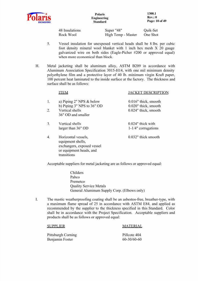
2. Insulation for vessels and exchangers with a diameter larger than available premolded pipe insulation and for equipment shall be calcium silicate orexpanded perlite block. Recommended manufacturers and trade namesare the same as for pipe insulation.
3. Expansion joint material shall be loose mineral fiber. It shall be oil free
and suitable for use within temperature limits of 140o
F to 1200o
F (ASTMC592, Class II).
4. Insulation cement shall conform to ASTM C195 or ASTM C449. Onecoat finishing cement may be used up to the thickness recommended bythe Manufacturer. Mineral wool conforming to ASTM C195, is preferredfor thicknesses greater than 1 inch because of its better insulation property.Insulating cement shall be reinforced when recommended by theManufacturer. Acceptable manufacturers shall be as follows or approvedequal:
BRAND NAME MINERAL WOOL ONE COATMANUFACTURER ASTM C195 ASTM C449
Celotex MW-50 MW-1Pabco Super Caltemp PabcoteManville Corp. #460 #375Keene Corp. Super 1900 Super PowerhouseRyder Industries Thermokote MW Thermocote #1P-K Insulation Super Stick Quick CoatInsulating Industries Smooth Kote -
Triple I
8/12/2019 1300.1 - Hot Insinsulation
http://slidepdf.com/reader/full/13001-hot-insinsulation 10/49
8/12/2019 1300.1 - Hot Insinsulation
http://slidepdf.com/reader/full/13001-hot-insinsulation 11/49
PolarisEngineering
Standard
1300.1Rev.: 0Page: 11 of 49
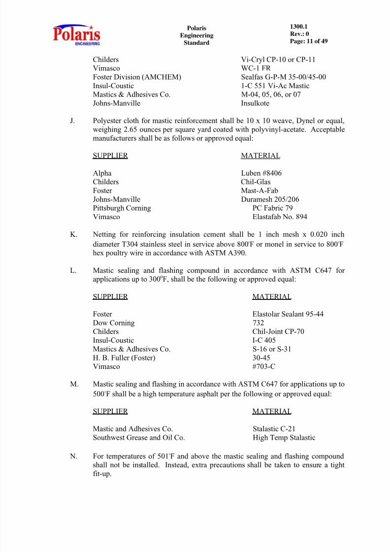
Childers Vi-Cryl CP-10 or CP-11Vimasco WC-1 FRFoster Division (AMCHEM) Sealfas G-P-M 35-00/45-00Insul-Coustic 1-C 551 Vi-Ac Mastic
Mastics & Adhesives Co. M-04, 05, 06, or 07Johns-Manville Insulkote
J. Polyester cloth for mastic reinforcement shall be 10 x 10 weave, Dynel or equal,weighing 2.65 ounces per square yard coated with polyvinyl-acetate. Acceptablemanufacturers shall be as follows or approved equal:
SUPPLIER MATERIAL
Alpha Luben #8406Childers Chil-Glas
Foster Mast-A-FabJohns-Manville Duramesh 205/206Pittsburgh Corning PC Fabric 79Vimasco Elastafab No. 894
K. Netting for reinforcing insulation cement shall be 1 inch mesh x 0.020 inchdiameter T304 stainless steel in service above 800 o F or monel in service to 800 o Fhex poultry wire in accordance with ASTM A390.
L. Mastic sealing and flashing compound in accordance with ASTM C647 forapplications up to 300 oF, shall be the following or approved equal:
SUPPLIER MATERIAL
Foster Elastolar Sealant 95-44Dow Corning 732Childers Chil-Joint CP-70Insul-Coustic I-C 405Mastics & Adhesives Co. S-16 or S-31H. B. Fuller (Foster) 30-45Vimasco #703-C
M. Mastic sealing and flashing in accordance with ASTM C647 for applications up to500 o F shall be a high temperature asphalt per the following or approved equal:
SUPPLIER MATERIAL
Mastic and Adhesives Co. Stalastic C-21Southwest Grease and Oil Co. High Temp Stalastic
N. For temperatures of 501 o F and above the mastic sealing and flashing compoundshall not be installed. Instead, extra precautions shall be taken to ensure a tightfit-up.
8/12/2019 1300.1 - Hot Insinsulation
http://slidepdf.com/reader/full/13001-hot-insinsulation 12/49
PolarisEngineering
Standard
1300.1Rev.: 0Page: 12 of 49
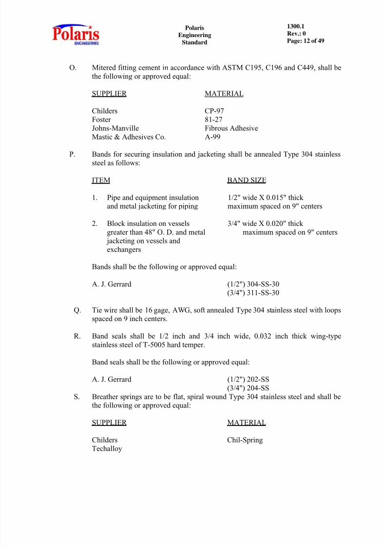
O. Mitered fitting cement in accordance with ASTM C195, C196 and C449, shall bethe following or approved equal:
SUPPLIER MATERIAL
Childers CP-97Foster 81-27Johns-Manville Fibrous AdhesiveMastic & Adhesives Co. A-99
P. Bands for securing insulation and jacketing shall be annealed Type 304 stainlesssteel as follows:
ITEM BAND SIZE
1. Pipe and equipment insulation 1/2" wide X 0.015" thickand metal jacketing for piping maximum spaced on 9" centers
2. Block insulation on vessels 3/4" wide X 0.020" thickgreater than 48" O. D. and metal maximum spaced on 9" centers
jacketing on vessels andexchangers
Bands shall be the following or approved equal:
A. J. Gerrard (1/2") 304-SS-30(3/4") 311-SS-30
Q. Tie wire shall be 16 gage, AWG, soft annealed Type 304 stainless steel with loopsspaced on 9 inch centers.
R. Band seals shall be 1/2 inch and 3/4 inch wide, 0.032 inch thick wing-typestainless steel of T-5005 hard temper.
Band seals shall be the following or approved equal:
A. J. Gerrard (1/2") 202-SS(3/4") 204-SS
S. Breather springs are to be flat, spiral wound Type 304 stainless steel and shall bethe following or approved equal:
SUPPLIER MATERIAL
Childers Chil-SpringTechalloy
8/12/2019 1300.1 - Hot Insinsulation
http://slidepdf.com/reader/full/13001-hot-insinsulation 13/49
PolarisEngineering
Standard
1300.1Rev.: 0Page: 13 of 49
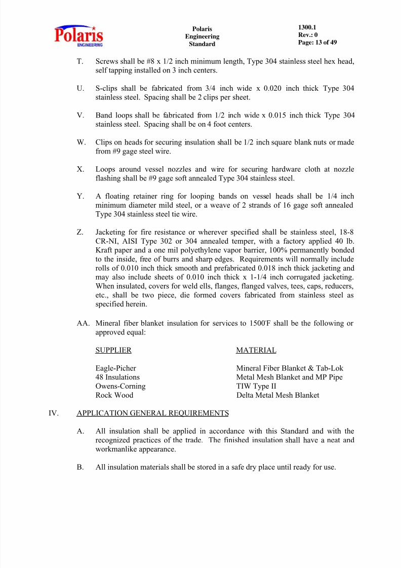
T. Screws shall be #8 x 1/2 inch minimum length, Type 304 stainless steel hex head,self tapping installed on 3 inch centers.
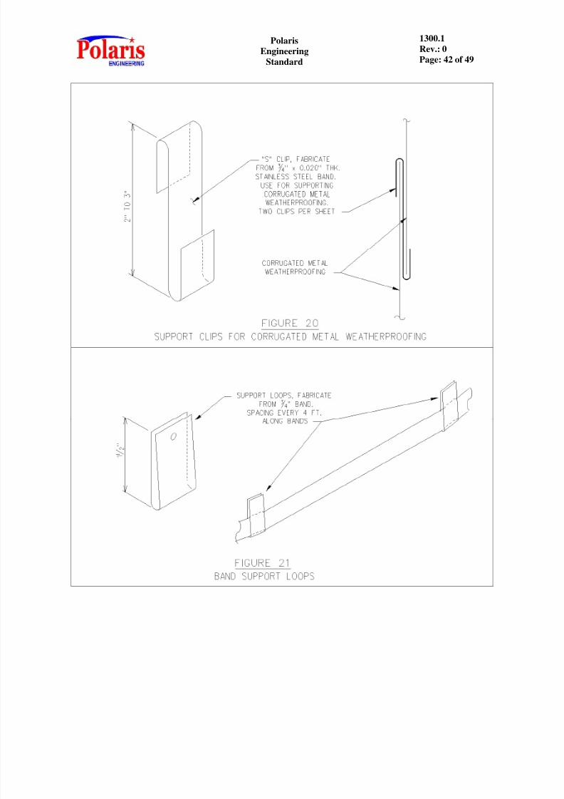
U. S-clips shall be fabricated from 3/4 inch wide x 0.020 inch thick Type 304
stainless steel. Spacing shall be 2 clips per sheet.
V. Band loops shall be fabricated from 1/2 inch wide x 0.015 inch thick Type 304stainless steel. Spacing shall be on 4 foot centers.
W. Clips on heads for securing insulation shall be 1/2 inch square blank nuts or madefrom #9 gage steel wire.
X. Loops around vessel nozzles and wire for securing hardware cloth at nozzleflashing shall be #9 gage soft annealed Type 304 stainless steel.
Y. A floating retainer ring for looping bands on vessel heads shall be 1/4 inchminimum diameter mild steel, or a weave of 2 strands of 16 gage soft annealedType 304 stainless steel tie wire.
Z. Jacketing for fire resistance or wherever specified shall be stainless steel, 18-8CR-NI, AISI Type 302 or 304 annealed temper, with a factory applied 40 lb.Kraft paper and a one mil polyethylene vapor barrier, 100% permanently bondedto the inside, free of burrs and sharp edges. Requirements will normally includerolls of 0.010 inch thick smooth and prefabricated 0.018 inch thick jacketing andmay also include sheets of 0.010 inch thick x 1-1/4 inch corrugated jacketing.When insulated, covers for weld ells, flanges, flanged valves, tees, caps, reducers,
etc., shall be two piece, die formed covers fabricated from stainless steel asspecified herein.
AA. Mineral fiber blanket insulation for services to 1500 o F shall be the following orapproved equal:
SUPPLIER MATERIAL
Eagle-Picher Mineral Fiber Blanket & Tab-Lok48 Insulations Metal Mesh Blanket and MP PipeOwens-Corning TIW Type II
Rock Wood Delta Metal Mesh BlanketIV. APPLICATION GENERAL REQUIREMENTS
A. All insulation shall be applied in accordance with this Standard and with therecognized practices of the trade. The finished insulation shall have a neat andworkmanlike appearance.
B. All insulation materials shall be stored in a safe dry place until ready for use.

8/12/2019 1300.1 - Hot Insinsulation
http://slidepdf.com/reader/full/13001-hot-insinsulation 14/49
PolarisEngineering
Standard
1300.1Rev.: 0Page: 14 of 49
C. Insulation shall be protected from damage and detrimental weather conditionsduring all stages of application. Insulation which has become wet or damagedwill be allowed to dry, be repaired or replaced, whichever is necessary asdetermined by the Client's Representative, before proceeding with the application
of succeeding courses.
D. Insulation shall not be applied until all hydrostatic or pneumatic testing iscompleted. If insulation must begin prior to such testing, all weld and mechanical
joints shall be left uncovered until all testing is completed. Vessel welds may beinsulated if the vessel has been pressure tested in the shop.
E. All surfaces shall be free of oil, grease, loose scale, dirt or other foreign matter before applying insulation.
F. The jobsite shall be kept free of insulation debris, scrap and unused material.
Adjacent equipment shall be kept free of spattered material.
G. Double layers shall be applied where specified. Single layer should be usedwhere specified; however, multiple layer construction may be used whenapproved by the Client because of stock size availability.
H. Care shall be taken to avoid contact between dissimilar materials which mightcause galvanic corrosion.
I. Studs, pins, clips or other attachments shall not be field welded to postweld heattreated vessels, tanks or piping. Any attachment shall be presented to the Client
for approval prior to first application.J. Tie wires and bands shall be drawn taut (not hammered) to embed them flush with
the face of the insulation. Ends of tie wires shall be firmly twisted. The twistedwire ends and seals of bands shall be embedded into the insulation. Bands shall
be machine stretched and sealed in place under tension. Tie wire and bandingseparation shall be on 9 inch centers.
K. Insulation shall be applied with joints tightly butted together. Single layer pipingand block insulation shall be applied with longitudinal joints staggered. Multiplelayer construction shall be applied with all joints staggered and each layer shall besecured independently with tie wires on 9 inch centers.
L. Damaged areas shall be repaired and all gaps greater than 1/16 inch shall be pointed with insulating cement.
M. Application of insulation for personnel protection shall be the same as for heatconservation except for possible differences in thickness.
N. Special care shall be taken to keep sheets of aluminum jacketing dry prior toapplication in order to prevent water stain between sheets.

8/12/2019 1300.1 - Hot Insinsulation
http://slidepdf.com/reader/full/13001-hot-insinsulation 15/49
PolarisEngineering
Standard
1300.1Rev.: 0Page: 15 of 49
O. Special care shall be taken to keep mastic joint sealers and other coatings coolenough to prevent shortening of shelf and pot life.
P. A minimum clearance of 3/4 inch shall be maintained between the exterior of the
insulation surface and any obstruction such as stairways, platforms or pipingunless approved by Owner.
V. APPLICATION OF PIPING INSULATION AND WEATHER BARRIER
A. Application of Insulation
1. Pipe shall be insulated with pipe covering of the thickness determined by theContractor, per Section IX of this Standard.
2. The insulation on pipe 20 inch and less in diameter shall be secured with tie
wire or bands. Insulation on pipe greater than 20 inch diameter shall besecured with bands.
3. The bands or wires for single layer and outer layers shall be on 9 inchcenters. When double layers are used, both layers shall be secured on 9 inchcenters.
4. Unless otherwise specified, insulation on vertical runs of piping, or pipinginclined 45 o or more, 3 inch in diameter and larger shall be supported on 12foot maximum centers by welded lugs or support rings (where welding is
permitted) or bolted lugs extending to within 1/2 inch of the outside surface
of the insulation. Supports shall be installed above all flanges in verticallines and located as required to allow removal of flange bolts. Supports shall be supplied and installed by the Insulation Applicator. Carbon steel lugs orsupport rings shall have surface preparation per POLARIS EngineeringStandard 1400.1.
5. On horizontal piping operating above 300 oF, expansion joints shall be provided on centers as shown below. On vertical piping, expansion jointsshall be provided at the insulation support. The joints shall be 1 inch wideand filled with mineral fiber. When applying double layer pipe insulation,the expansion joint on the outer layer shall be offset 12 inch from the joint ofthe inner layer.
OPERATING TEMPERATURE EXPANSION JOINT SPACING (Feet)
Less than 300 oF None301oF to 450 oF 51451oF to 550 oF 39551oF to 700 oF 24More than 700 oF 18

8/12/2019 1300.1 - Hot Insinsulation
http://slidepdf.com/reader/full/13001-hot-insinsulation 16/49
PolarisEngineering
Standard
1300.1Rev.: 0Page: 16 of 49
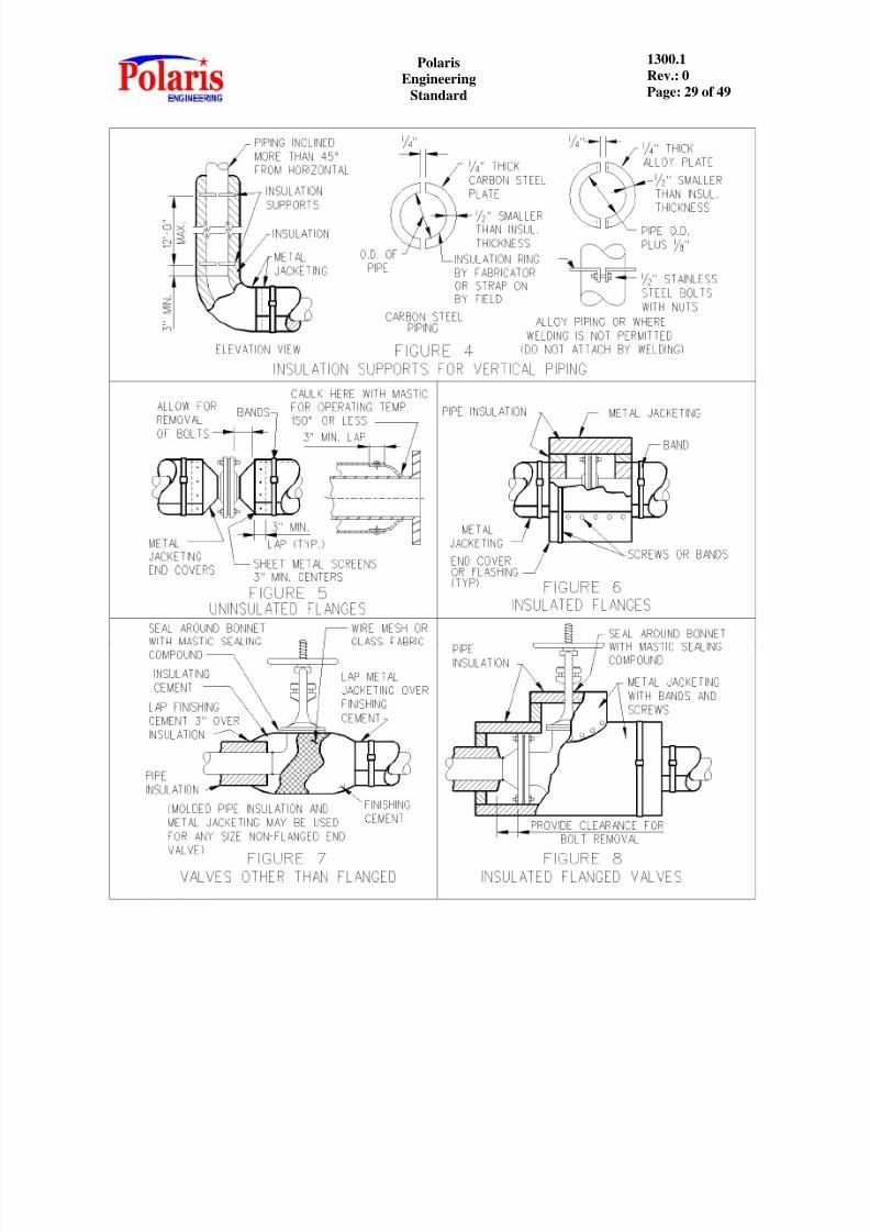
6. Pipe insulation shall be stopped short of all uninsulated flanges and unionsand trimmed at a 45 o angle for a sufficient distance to permit removal of the
bolts or slipping off the union nut. Required clearance is stud length plus 1/4
inch. For prefabricated metal bevel collar use, insulation shall be cut at thesame angle as the collar.
7. Bent pipe shall be insulated with pipe covering similar to straight pipe,except miter-cut joints shall be filled with insulating cement.
8. Flanges, unions and 3 inch and larger valve bodies requiring insulation shall be insulated by the "tube method" using larger nesting sizes of insulation ofthe same type and thickness as the adjacent pipe covering, or with pipeinsulation and blocks, filling the cracks with insulation cement. Forlocations requiring frequent removal for maintenance or for reasons of
economy, reusable blanket insulation may be advantageous. (Refer toPOLARIS Engineering Standard 1300.6).
9. Screwed and welded fittings (including valve bodies, only where specified),1/2 inch and smaller shall be insulated with insulating cement applied in 1/2inch layers to a thickness equal to that of the adjacent piping. Fittings,valves and flanges where specified, 3/4 inch and larger, shall be insulatedwith preformed sectional pipe insulation, securely wired in place on 3 inchcenters over the long radius on ells.
10. Pipe sizes larger than 36 inch O. D. shall be insulated as described for
vessels.B. Application of Weather Barrier
1. Metal jackets shall be applied with all joints lapped 3 inch minimum, sealedwith a silicone sealer and positioned to shed moisture. Longitudinal andvertical joints shall be away from the prevailing wind and/or positioned foraesthetic appeal. The bands shall cover the circumferential lap seams of themetal jacket.
2. The jackets shall be secured by stainless steel bands on 9 inch centers.Screws on 3 inch maximum centers shall be used only where necessary, suchas for "touch up", additional securement of bands, and on irregular surfacessuch as miter joints.
3. Fittings, 1/2 inch and smaller may have a 1/16 inch thick coat ofweatherproofing mastic reinforced with polyester fabric covered with a
preformed metal jacket. This finish shall extend approximately 3 inch underthe adjacent pipe weatherproofing jacket. Joints between mastic and pipe
jacket shall be sealed with a silicone sealer to prevent entrance of moisture.
8/12/2019 1300.1 - Hot Insinsulation
http://slidepdf.com/reader/full/13001-hot-insinsulation 17/49
PolarisEngineering
Standard
1300.1Rev.: 0Page: 17 of 49
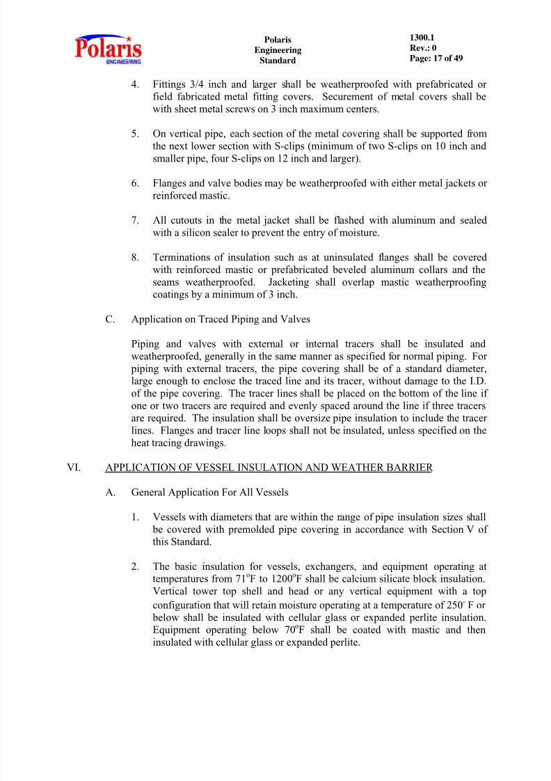
4. Fittings 3/4 inch and larger shall be weatherproofed with prefabricated orfield fabricated metal fitting covers. Securement of metal covers shall bewith sheet metal screws on 3 inch maximum centers.
5. On vertical pipe, each section of the metal covering shall be supported fromthe next lower section with S-clips (minimum of two S-clips on 10 inch andsmaller pipe, four S-clips on 12 inch and larger).
6. Flanges and valve bodies may be weatherproofed with either metal jackets orreinforced mastic.
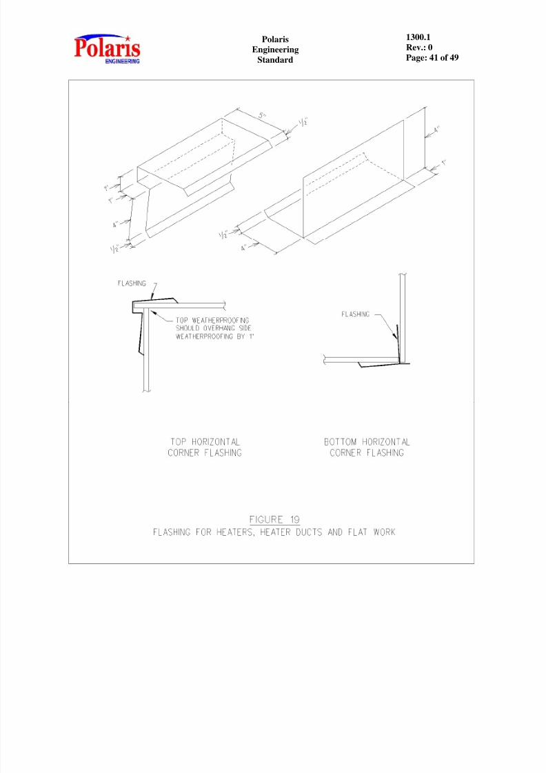
7. All cutouts in the metal jacket shall be flashed with aluminum and sealedwith a silicon sealer to prevent the entry of moisture.
8. Terminations of insulation such as at uninsulated flanges shall be covered
with reinforced mastic or prefabricated beveled aluminum collars and theseams weatherproofed. Jacketing shall overlap mastic weatherproofingcoatings by a minimum of 3 inch.
C. Application on Traced Piping and Valves
Piping and valves with external or internal tracers shall be insulated andweatherproofed, generally in the same manner as specified for normal piping. For
piping with external tracers, the pipe covering shall be of a standard diameter,large enough to enclose the traced line and its tracer, without damage to the I.D.of the pipe covering. The tracer lines shall be placed on the bottom of the line if
one or two tracers are required and evenly spaced around the line if three tracersare required. The insulation shall be oversize pipe insulation to include the tracerlines. Flanges and tracer line loops shall not be insulated, unless specified on theheat tracing drawings.
VI. APPLICATION OF VESSEL INSULATION AND WEATHER BARRIER
A. General Application For All Vessels
1. Vessels with diameters that are within the range of pipe insulation sizes shall be covered with premolded pipe covering in accordance with Section V ofthis Standard.
2. The basic insulation for vessels, exchangers, and equipment operating attemperatures from 71 oF to 1200 oF shall be calcium silicate block insulation.Vertical tower top shell and head or any vertical equipment with a topconfiguration that will retain moisture operating at a temperature of 250 o F or
below shall be insulated with cellular glass or expanded perlite insulation.Equipment operating below 70 oF shall be coated with mastic and theninsulated with cellular glass or expanded perlite.

8/12/2019 1300.1 - Hot Insinsulation
http://slidepdf.com/reader/full/13001-hot-insinsulation 18/49
PolarisEngineering
Standard
1300.1Rev.: 0Page: 18 of 49
3. Block insulation on vessels, tubular equipment and header boxes of aircooler exchangers shall be applied with a stagger joint arrangement with alledges butted together. Nozzle projections through insulation shall beinsulated to the same thickness as the vessel. Securement shall be with 3/4
inch x 0.020 inch thick bands spaced on 9 inch centers.
4. Blanket insulation on vertical tubular equipment shall be applied with astagger joint arrangement. Top and bottom edges shall be securely tied overthe support rings with wire on 12 inch centers. Vertical and horizontal seamsshall be laced together by interlocking the wire mesh with 0.051 inchdiameter wire where necessary. The insulation shall then be secured in placewith 3/4 inch wide x 0.020 inch thick bands spaced on 9 inch centers.
Nozzle projections through insulation shall be insulated to the samethickness as the vessel.
5. Exposed vessel and tubular equipment heads shall have block insulationshaped so that all sections are snug and tight. The insulation shall be lacedas on the straight sides, and secured with a 1/4 inch round steel rod floatingring in the center and bands on 12 inch maximum centers at the tangent line.An alternative to the 1/4 inch steel rod is to secure the insulation with adouble twisted stainless steel tie wire.
6. Unexposed heads on vessels and tubular equipment shall have blockinsulation shaped so that all sections are snug and tight. The insulation shall
be laced as on the straight sides and secured by a 1/4 inch round steel rodfloating ring in the center and bands on 12 inch maximum centers at the
tangent line. A floating ring shall be provided for each layer of insulation.An alternative to the 1/4 inch steel rod is to secure the insulation with adouble twisted stainless steel tie wire. Over the blanket, a 3/8 inch thick(when dry) layer of insulation and finishing cement shall be applied.
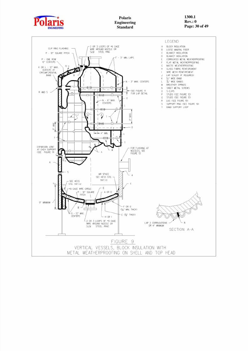
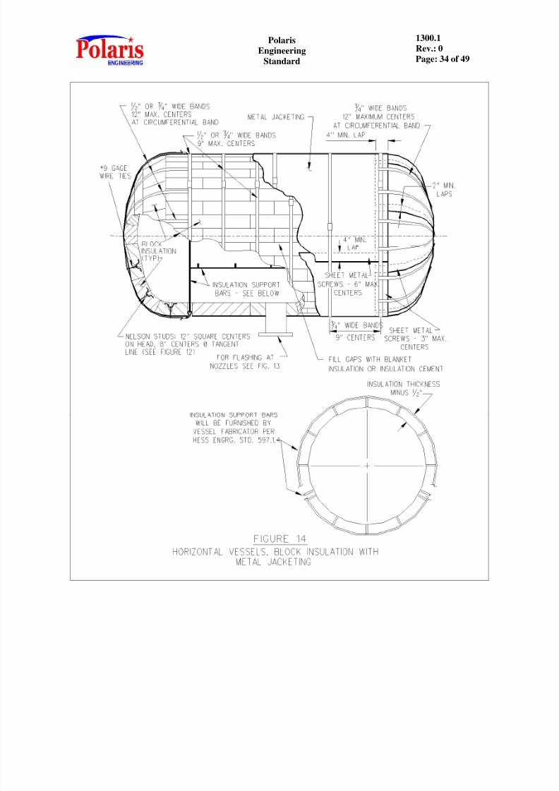
7. Straight shells of all vertical vessels shall be weatherproofed with 1-1/4 inchcorrugated metal jacketing. Straight shells of all horizontal vessels shall beweatherproofed with smooth metal jacketing. (Refer to Section III.H of thisStandard).
a. Jacketing shall be secured with banding located over everycircumferential lap of the jacketing and on 9 inch maximumcenters. All bands except those on circumferential laps shall besupported by band support loops fabricated from 3/4 inch wide
bands on 4 foot centers with a minimum of four per vessel.Stainless steel sheet metal screws shall be applied midway betweeneach band on longitudinal seams (approximately on 3 inch centers)only.
b. The minimum lap for all jacketing shall be 3 inches on piping and4 inches on vessels, exchangers and other equipment.

8/12/2019 1300.1 - Hot Insinsulation
http://slidepdf.com/reader/full/13001-hot-insinsulation 19/49
PolarisEngineering
Standard
1300.1Rev.: 0Page: 19 of 49
8. Insulation support rings and insulation tie supports will be provided by theVessel Fabricator. For details, refer to POLARIS Engineering Standard597.1.2 for vertical vessels and 597.1.4 for horizontal vessels.
9. The insulating blocks shall be covered directly with aluminum sheet metal jacketing. No finishing cement is required under the metal except for repairor to fill gaps.
10. Fixed heads may be weatherproofed with fabricated metal covers.
11. Support lugs for ladders, platforms, piping, etc., shall be flashed and sealedwith sealing compound.
12. Breather springs shall be installed in each band securing jacketing on vesseland tubular equipment when and as required by the following:
DIAMETER
USE SPRINGS IFOPERATING TEMP.IS EQUAL ORGREATER THAN
MINIMUM NUMBER OF SPRINGS PER BAND
REGULAR (4” LONG)
Below 4’ 0”4” - 0” thru 7’ – 11”8’ – 0” thru 14’ – 11”15’ – 0” thru 30’ – 4”
900 oF600 oF200 oFAll Temps.
111 for T > 600 oF2 for T > 600 oF(180 o Apart)
(For diameter larger than 30’ –0”, contact the Owner).
The bands shall be installed with sufficient tension to retain the band whencold, but not so much that permanent set can occur during operation.
13. In providing weather protection for equipment operating at temperaturesfrom 71 o F to 250 o F, extra precautions shall be observed to prevent theentry of moisture between the insulation and the shell of the equipment.
B. Application of Insulation on Vertical Vessels
1. The shell of vertical vessels shall be insulated down to the vessel-skirt joint. When the vessel temperature is equal or greater than 600 oF, then theinsulation shall extend a minimum of 9 inches below the vessel-skirt joint.
2. Vessel skirts shall not be insulated. If the vessel skirt is fireproofed, theinsulation shall extend down to the fireproofing, where the bottominsulation support ring will be located.
3. Vertical vessel insulation shall rest on supporting angle rings spaced at12'-1" maximum spacing. Support ring design and installation shall be asshown in this Standard or an equivalent design approved by the Client.
8/12/2019 1300.1 - Hot Insinsulation
http://slidepdf.com/reader/full/13001-hot-insinsulation 20/49
PolarisEngineering
Standard
1300.1Rev.: 0Page: 20 of 49
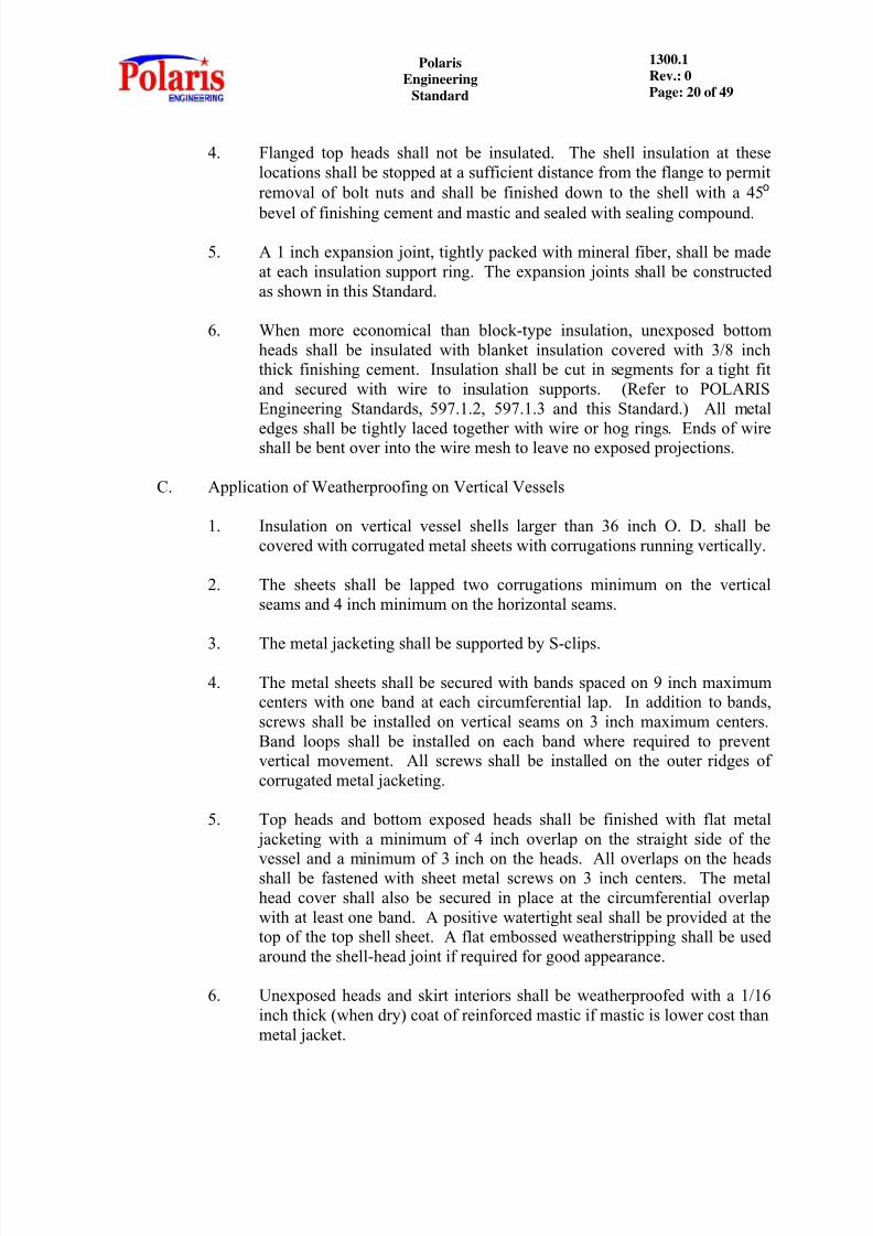
4. Flanged top heads shall not be insulated. The shell insulation at theselocations shall be stopped at a sufficient distance from the flange to permitremoval of bolt nuts and shall be finished down to the shell with a 45 o
bevel of finishing cement and mastic and sealed with sealing compound.
5. A 1 inch expansion joint, tightly packed with mineral fiber, shall be madeat each insulation support ring. The expansion joints shall be constructedas shown in this Standard.
6. When more economical than block-type insulation, unexposed bottomheads shall be insulated with blanket insulation covered with 3/8 inchthick finishing cement. Insulation shall be cut in segments for a tight fitand secured with wire to insulation supports. (Refer to POLARISEngineering Standards, 597.1.2, 597.1.3 and this Standard.) All metal
edges shall be tightly laced together with wire or hog rings. Ends of wireshall be bent over into the wire mesh to leave no exposed projections.
C. Application of Weatherproofing on Vertical Vessels
1. Insulation on vertical vessel shells larger than 36 inch O. D. shall becovered with corrugated metal sheets with corrugations running vertically.
2. The sheets shall be lapped two corrugations minimum on the verticalseams and 4 inch minimum on the horizontal seams.
3. The metal jacketing shall be supported by S-clips.
4. The metal sheets shall be secured with bands spaced on 9 inch maximumcenters with one band at each circumferential lap. In addition to bands,screws shall be installed on vertical seams on 3 inch maximum centers.Band loops shall be installed on each band where required to preventvertical movement. All screws shall be installed on the outer ridges ofcorrugated metal jacketing.
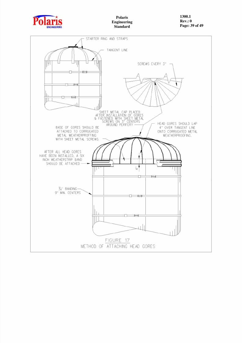
5. Top heads and bottom exposed heads shall be finished with flat metal jacketing with a minimum of 4 inch overlap on the straight side of the
vessel and a minimum of 3 inch on the heads. All overlaps on the headsshall be fastened with sheet metal screws on 3 inch centers. The metalhead cover shall also be secured in place at the circumferential overlapwith at least one band. A positive watertight seal shall be provided at thetop of the top shell sheet. A flat embossed weatherstripping shall be usedaround the shell-head joint if required for good appearance.
6. Unexposed heads and skirt interiors shall be weatherproofed with a 1/16inch thick (when dry) coat of reinforced mastic if mastic is lower cost thanmetal jacket.

8/12/2019 1300.1 - Hot Insinsulation
http://slidepdf.com/reader/full/13001-hot-insinsulation 21/49
PolarisEngineering
Standard
1300.1Rev.: 0Page: 21 of 49
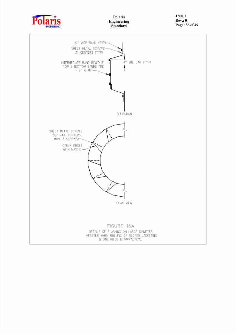
7. Transition and stiffener rings shall be finished with metal jacketing andweatherproof seams. The jacketing shall extend under the upper shell
jacketing and down over the lower shell jacketing a minimum of 4 incheseach. The overlap shall be fastened to the jacketing on the shell with sheet
metal screws on 3 inch centers. The metal covers shall also be secured in place at the circumferential overlap with a band.
D. Application of Insulation on Horizontal Vessels
1. Insulation on horizontal vessels and drums shall be secured in the samemanner as vertical vessels except that no support rings are required onvessels less than 6 feet diameter. On horizontal vessels 6 feet diameterand over, support rods shall be provided by the Vessel Fabricator.
2. No expansion joints are required for horizontal vessels operating at 300 oF
or less and having a tangent length of 20 feet or less. Those longer than20 feet or operating above 300 oF shall be provided with a 1 inchexpansion joint for each 15 feet of length.
E. Application of Weatherproofing on Horizontal Vessels
1. Shells of horizontal vessels shall be covered with smooth sheets. Thesheets shall be lapped 4 inches minimum on both the circumferential andlongitudinal seams.
2. Sheets shall be secured by sheet metal screws on the longitudinal seams
only. Sheet metal screws shall be spaced on 3 inch maximum centers.The jacketing shall be secured circumferentially with bands spaced on 9inch maximum centers.
3. Heads on horizontal vessels shall be finished with metal jacketing withweatherproof seams. Gore seams shall be lapped 2 inch minimum with aminimum of 4 inch turned under the shell jacketing. The overlaps shall befastened with sheet metal screws on 3 inch centers. The metal head coversshall also be secured in place at the circumferential overlap with at leastone band.
VII. APPLICATION ON EXCHANGERS
A. Shell and Tube Type
1. The shell shall be covered with block insulation of the thicknessdetermined by the Economic Thickness Table (See Section IX). Ingeneral, the application shall be as described for horizontal vessels exceptas modified herein. Insulation shall be stopped a sufficient distance fromeach flange to permit removal of the flange bolts, finished with a 45 o bevelof finishing cement and mastic, and sealed with sealing compound.

8/12/2019 1300.1 - Hot Insinsulation
http://slidepdf.com/reader/full/13001-hot-insinsulation 22/49
PolarisEngineering
Standard
1300.1Rev.: 0Page: 22 of 49
2. Expansion joints shall be provided, if required, as specified for horizontalvessels.
3. The rear head (non-removable) shall be insulated with insulating cement
of the same thickness as the shell covering. Heads 3 feet in diameter orlarger may be covered with block if this is more economical.
4. The cement shall be applied in layers of 3/4 inch to 1 inch thickness. Overevery second layer, poultry netting shall be carefully fitted and stretched in
place. The netting shall be secured with stainless steel wire laced through1/2 inch square nuts tack- welded to the heads on 8 inch centers bothways. The insulation shall be stopped a sufficient distance from the flangeto permit removal of the bolts and shall be finished down to the heads witha 45 o bevel with finishing cement.
5. Insulated shell and tube exchangers shall have the channels, channelcovers, tubesheet flanges and flanged rear heads provided with removablealuminum clad insulation. See Figure 29.
6. Weather-barrier shall be as follows, (except for reusable blanket covers):
a. The shells shall be covered with smooth metal. Exchanger heads,channel and flanges requiring insulation shall normally beinsulated with removable insulation covers that are aluminum cladon the interior and exterior surfaces and have hold-down clips andhandles for ease of removal. Insulation in the removable covers
shall be mineral fiber blanket type. Stationary heads shall becovered with smooth metal. Soft fabric covers are not preferred.
b. Application shall be generally the same as specified for horizontalvessels, except sheet metal screws on longitudinal joints shall beon 3 inch maximum centers.
c. All bevels shall be sealed with mastic and sealing compound. Themastic shall extend under the metal at least 4 inches.
B. Double Pipe Hairpin Type
1. When an exchanger consists of only one section, the twin shells shall becovered as a unit with pipe covering and block of the thickness specifiedin Section IX. A half section of pipe covering shall be applied to eachshell and the space between filled with block insulation. When two ormore sections are stacked together they may be encased.
2. The pipe covering and block shall be secured with bands or loops of 16gage stainless steel wire on 9 inch centers. The wire ends shall be tightlytwisted and embedded into the insulation.

8/12/2019 1300.1 - Hot Insinsulation
http://slidepdf.com/reader/full/13001-hot-insinsulation 23/49
PolarisEngineering
Standard
1300.1Rev.: 0Page: 23 of 49
3. The pipe covering and block shall be stopped at a sufficient distance fromflanges to permit removal of the bolts, finished down to the shells with a45o bevel of finishing cement and mastic, and sealed with sealingcompound. The annular space at the tube end shall be finished with
insulating cement.
4. No expansion joints are to be provided for exchangers when the coveringis of a combination or two-layer construction. The second layer shall beapplied with staggered joints, and each layer shall be securedindependently as described above.
5. Weatherproofing materials and application shall be the same as specifiedfor shell and tube exchangers.
VIII. EQUIPMENT AND INSTRUMENTS
A. Irregular Equipment Surfaces
1. Equipment of irregular shape shall be insulated only when specificallynoted on the equipment paint insulation and lining schedule. Thisequipment may include, but is not limited to, such items as steam turbinecasings, centrifugal pump casings, reciprocating pump steam and liquidends, etc.
2. Pumps and turbines, when insulated, shall be insulated with insulationheld securely in place. (Refer to POLARIS Engineering Standard 1300.6
For Reusable Blanket Insulation).3. The insulation adjacent to casing flanges, sentinel valves and the like,
shall be beveled at 45 o to the equipment to permit removal of the flange bolts, valves, etc., with minimum damage to the insulation.
4. A 1/16 inch minimum thick (when dry) reinforced mastic weatherproofingshall be applied over the pipe, block and/or the insulating cement.
5. Rotating equipment and drivers requiring insulation shall normally beinsulated with removable insulation covers having hold-down clips,handles for ease of removal, and an aluminum jacket on the interior andexterior surface. Soft fabric covers are not preferred.
B. Instruments
1. All instruments and their impulse lines which are steam traced shall beinsulated.
2. Instrument piping operating over 140 oF shall be insulated for personnel protection in accordance with Paragraph II.B. of this Standard.

8/12/2019 1300.1 - Hot Insinsulation
http://slidepdf.com/reader/full/13001-hot-insinsulation 24/49
PolarisEngineering
Standard
1300.1Rev.: 0Page: 24 of 49
3. Insulation for instruments shall be applied so that there is no interferencewith either the operation or function of the instrument and that all gauges,dials, sight glasses, etc., will remain unobstructed and clearly in view.Combinations of the insulating materials covered by this Standard which
best accommodate each particular item shall be used, subject to theClient's approval.
IX. ECONOMIC THICKNESS TABLE
Unless otherwise specified, the Contractor shall develop for approval by the Client, the"Economic Insulation Thickness Table for Heat Conservation" and "Minimum Thicknessfor Burn Protection Table" using the following criteria:
A. Because of the wide variations in climatic conditions between plant locations theContractor shall obtain from the Client the following information on which the
analysis should be based.
1. Heat value of fuel in $/MM BTU.2. Annual average air temperature at the plant.3. Operating hours/year for the unit.4. Payout basis in years.
B. Surfaces greater than a 24 inch diameter are defined as flat for purposes ofinsulation heat loss and cost calculations.
C. Double layer construction shall be used for the following conditions:
1. If calculated economic thickness is greater than 2-1/2 inches.
2. If process temperature is 600 o F or above and the calculated economicthickness is 2-1/2 inches or more.
3. If process temperature is 900 o F or above.
D. Thickness for personnel protection shall be based on calcium silicate insulationthickness required to maintain the external surface of the aluminum jacket at or
below 140 o F in still air.
E. The format of the Insulation Thickness Tables shall be presented in a form similarto that of Attachment A and B. At a minimum, the Insulation Thickness Tablesshall list:
1. Type of insulation2. Insulation/jacketing material3. Project design conditions (from Section IX.A of this Standard)4. Pipe size5. Process temperature ranges6. Economic insulation thickness7. Single/multiple layer designation

8/12/2019 1300.1 - Hot Insinsulation
http://slidepdf.com/reader/full/13001-hot-insinsulation 25/49
PolarisEngineering
Standard
1300.1Rev.: 0Page: 25 of 49
F. The thicknesses presented in the Insulation Thickness Tables are nominal. Wherethe material used is furnished in thicknesses different from that presented, use ofthe nearest commercially available thickness is acceptable.
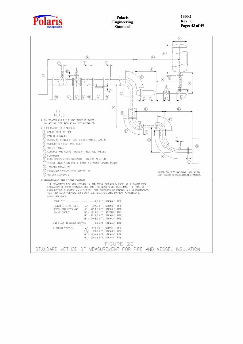
X. STANDARD METHOD OF MEASURING PIPE LENGTH FOR QUOTATIONS
Unless otherwise specified or approved by the Client, quotations shall be based on Figure22 which is based on the National Insulation Contractors Standard.
XI. FIGURES
A. The insulation requirements in this Standard including the following Figures areminimum requirements and designs which are approved by the Client. Alternatedesigns other than those shown which would provide better insulation
performance or lower cost with acceptable performance are encouraged, but must
be approved in advance by the Client.

8/12/2019 1300.1 - Hot Insinsulation
http://slidepdf.com/reader/full/13001-hot-insinsulation 26/49
PolarisEngineering
Standard
1300.1Rev.: 0Page: 26 of 49
ATTACHMENT A
ECONOMIC THICKNESS TABLE (4 YEAR PAYOUT)
NominalPipe Size(Inches)
Process Temperature, ºF
140to200
201to300
301to400
401to500
501to600
601to700
701to800
801to900
901to1000
1001to1100
1101to1200
Total Insulation Thickness (Inches)1-1/2 orSmaller
1 1 1 1 1-1/2 1-1/2 1-1/2 2 -2 -2 -2
2 1 1 1-1/2 1-1/2 1-1/2 2 2 2 -2-1/2 -2-1/2 -2-1/2
3 1 1-1/2 1-1/2 2 2 2-1/2 2-1/2 2-1/2 -2-1/2 -3 -3
4 1 1-1/2 1-1/2 2 2-1/2 2-1/2 2-1/2 -3 -3 -3-1/2 -3-1/2
6 1 1-1/2 2 2 2-1/2 2-1/2 -3 -3 -3-1/2 -3-1/2 -4
8 1-1/2 1-1/2 2 2-1/2 2-1/2 -3 -3 -3-1/2 -3-1/2 -4 -4-1/2
10 1-1/2 1-1/2 2 2-1/2 -3 -3 -3-1/2 -3-1/2 -4 -4-1/2 -4-1/2
12 1-1/2 2 2 2-1/2 -3 -3-1/2 -3-1/2 -4 -4-1/2 -4-1/2 -5
14 1-1/2 2 2-1/2 2-1/2 -3 -3-1/2 -4 -4-1/2 -4-1/2 -5 -5-1/2
16 1-1/2 2 2-1/2 3 -3 -3-1/2 -4 -4-1/2 -4-1/2 -5 -5-1/2
18 1-1/2 2 2-1/2 3 -3 -3-1/2 -4 -4-1/2 -4-1/2 -5 -5-1/2
20 1-1/2 2 2-1/2 3 -3 -3-1/2 -4 -4-1/2 -4-1/2 -5 -5-1/2
24 1-1/2 2 2-1/2 3 -3 -3-1/2 -4 -4-1/2 -4-1/2 -5 -5-1/2
Over 24”Dia. And
Flat
1-1/2 2 2-1/2 3 -3-1/2 -4 -4 -4-1/2 -5 -5-1/2 -6
Thicknesses shown are total thickness.Double-layer construction is indicated by a negative sign.
The above table is a sample only.
8/12/2019 1300.1 - Hot Insinsulation
http://slidepdf.com/reader/full/13001-hot-insinsulation 27/49
PolarisEngineering
Standard
1300.1Rev.: 0Page: 27 of 49
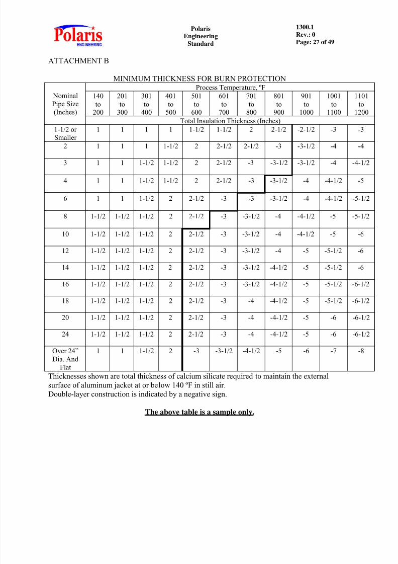
ATTACHMENT B
MINIMUM THICKNESS FOR BURN PROTECTION
NominalPipe Size(Inches)
Process Temperature, ºF
140to200
201to300
301to400
401to500
501to600
601to700
701to800
801to900
901to1000
1001to1100
1101to1200
Total Insulation Thickness (Inches)1-1/2 orSmaller
1 1 1 1 1-1/2 1-1/2 2 2-1/2 -2-1/2 -3 -3
2 1 1 1 1-1/2 2 2-1/2 2-1/2 -3 -3-1/2 -4 -4
3 1 1 1-1/2 1-1/2 2 2-1/2 -3 -3-1/2 -3-1/2 -4 -4-1/2
4 1 1 1-1/2 1-1/2 2 2-1/2 -3 -3-1/2 -4 -4-1/2 -5
6 1 1 1-1/2 2 2-1/2 -3 -3 -3-1/2 -4 -4-1/2 -5-1/2
8 1-1/2 1-1/2 1-1/2 2 2-1/2 -3 -3-1/2 -4 -4-1/2 -5 -5-1/2
10 1-1/2 1-1/2 1-1/2 2 2-1/2 -3 -3-1/2 -4 -4-1/2 -5 -6
12 1-1/2 1-1/2 1-1/2 2 2-1/2 -3 -3-1/2 -4 -5 -5-1/2 -6
14 1-1/2 1-1/2 1-1/2 2 2-1/2 -3 -3-1/2 -4-1/2 -5 -5-1/2 -6
16 1-1/2 1-1/2 1-1/2 2 2-1/2 -3 -3-1/2 -4-1/2 -5 -5-1/2 -6-1/2
18 1-1/2 1-1/2 1-1/2 2 2-1/2 -3 -4 -4-1/2 -5 -5-1/2 -6-1/2
20 1-1/2 1-1/2 1-1/2 2 2-1/2 -3 -4 -4-1/2 -5 -6 -6-1/2
24 1-1/2 1-1/2 1-1/2 2 2-1/2 -3 -4 -4-1/2 -5 -6 -6-1/2
Over 24”Dia. And
Flat
1 1 1-1/2 2 -3 -3-1/2 -4-1/2 -5 -6 -7 -8
Thicknesses shown are total thickness of calcium silicate required to maintain the externalsurface of aluminum jacket at or below 140 ºF in still air.
Double-layer construction is indicated by a negative sign.
The above table is a sample only.

8/12/2019 1300.1 - Hot Insinsulation
http://slidepdf.com/reader/full/13001-hot-insinsulation 28/49
8/12/2019 1300.1 - Hot Insinsulation
http://slidepdf.com/reader/full/13001-hot-insinsulation 29/49
PolarisEngineering
Standard
1300.1Rev.: 0Page: 29 of 49
8/12/2019 1300.1 - Hot Insinsulation
http://slidepdf.com/reader/full/13001-hot-insinsulation 30/49
PolarisEngineering
Standard
1300.1Rev.: 0Page: 30 of 49

8/12/2019 1300.1 - Hot Insinsulation
http://slidepdf.com/reader/full/13001-hot-insinsulation 31/49
PolarisEngineering
Standard
1300.1Rev.: 0Page: 31 of 49

8/12/2019 1300.1 - Hot Insinsulation
http://slidepdf.com/reader/full/13001-hot-insinsulation 32/49
PolarisEngineering
Standard
1300.1Rev.: 0Page: 32 of 49

8/12/2019 1300.1 - Hot Insinsulation
http://slidepdf.com/reader/full/13001-hot-insinsulation 33/49
PolarisEngineering
Standard
1300.1Rev.: 0Page: 33 of 49
8/12/2019 1300.1 - Hot Insinsulation
http://slidepdf.com/reader/full/13001-hot-insinsulation 34/49
PolarisEngineering
Standard
1300.1Rev.: 0Page: 34 of 49

8/12/2019 1300.1 - Hot Insinsulation
http://slidepdf.com/reader/full/13001-hot-insinsulation 35/49
PolarisEngineering
Standard
1300.1Rev.: 0Page: 35 of 49
8/12/2019 1300.1 - Hot Insinsulation
http://slidepdf.com/reader/full/13001-hot-insinsulation 36/49
PolarisEngineering
Standard
1300.1Rev.: 0Page: 36 of 49

8/12/2019 1300.1 - Hot Insinsulation
http://slidepdf.com/reader/full/13001-hot-insinsulation 37/49
PolarisEngineering
Standard
1300.1Rev.: 0Page: 37 of 49

8/12/2019 1300.1 - Hot Insinsulation
http://slidepdf.com/reader/full/13001-hot-insinsulation 38/49
PolarisEngineering
Standard
1300.1Rev.: 0Page: 38 of 49
8/12/2019 1300.1 - Hot Insinsulation
http://slidepdf.com/reader/full/13001-hot-insinsulation 39/49
PolarisEngineering
Standard
1300.1Rev.: 0Page: 39 of 49

8/12/2019 1300.1 - Hot Insinsulation
http://slidepdf.com/reader/full/13001-hot-insinsulation 40/49
PolarisEngineering
Standard
1300.1Rev.: 0Page: 40 of 49
8/12/2019 1300.1 - Hot Insinsulation
http://slidepdf.com/reader/full/13001-hot-insinsulation 41/49
PolarisEngineering
Standard
1300.1Rev.: 0Page: 41 of 49
8/12/2019 1300.1 - Hot Insinsulation
http://slidepdf.com/reader/full/13001-hot-insinsulation 42/49
PolarisEngineering
Standard
1300.1Rev.: 0Page: 42 of 49
8/12/2019 1300.1 - Hot Insinsulation
http://slidepdf.com/reader/full/13001-hot-insinsulation 43/49
PolarisEngineering
Standard
1300.1Rev.: 0Page: 43 of 49

8/12/2019 1300.1 - Hot Insinsulation
http://slidepdf.com/reader/full/13001-hot-insinsulation 44/49
PolarisEngineering
Standard
1300.1Rev.: 0Page: 44 of 49

8/12/2019 1300.1 - Hot Insinsulation
http://slidepdf.com/reader/full/13001-hot-insinsulation 45/49
PolarisEngineering
Standard
1300.1Rev.: 0Page: 45 of 49

8/12/2019 1300.1 - Hot Insinsulation
http://slidepdf.com/reader/full/13001-hot-insinsulation 46/49
PolarisEngineering
Standard
1300.1Rev.: 0Page: 46 of 49

8/12/2019 1300.1 - Hot Insinsulation
http://slidepdf.com/reader/full/13001-hot-insinsulation 47/49
PolarisEngineering
Standard
1300.1Rev.: 0Page: 47 of 49

8/12/2019 1300.1 - Hot Insinsulation
http://slidepdf.com/reader/full/13001-hot-insinsulation 48/49
PolarisEngineering
Standard
1300.1Rev.: 0Page: 48 of 49

8/12/2019 1300.1 - Hot Insinsulation
http://slidepdf.com/reader/full/13001-hot-insinsulation 49/49
PolarisEngineering
Standard
1300.1Rev.: 0Page: 49 of 49