13 0137011911 ch10 - insead · abstract complex products such as airplanes and automobiles are...
TRANSCRIPT

AbstractComplex products such as airplanes and automobiles are designed by networks of designteams working on different components, often across organizations. The challenge inmanaging these networks is to decompose the project into manageable pieces but thencoordinate the entire network to produce the best overall design. In this chapter, ManuelSosa offers insights on this challenge. He examines the design structure matrix (DSM) asa project management tool for planning complex development efforts and discusses theengineering and managerial implications of considering complex products as networks ofinterconnected subsystems and components. In particular, he considers the impact ofmodularity on interactions among subcomponents. Finally, he examines organizationalcommunications, overlaying product interfaces with communications interfaces of devel-opment teams to understand where communication links may be missing or unnecessary.The discussion offers insights on any complex design and coordination challenge, wherenetworks of individuals or teams work together to contribute to a larger whole.
Designing new and complex products requires the interplay of processes, products,and structures across networks of individuals and organizations. From a network perspective, processes are networks of design tasks, products are networks of inter-connected components, and organizations are networks of developers or design teamsthat interact when executing design tasks to develop new products. Because managing
165
Coordination Networks in Product Development
Manuel E. Sosa
10
13_0137011911_ch10.qxd 11/13/09 3:01 PM Page 165

interdependences is fundamental to developing new products, taking a network per-spective can advance our understanding of how to coordinate resources in complexdevelopment efforts.
Coordination is the result of both system decomposition and system integration. Forexample, in developing a product such as an airplane, managers decompose the overallproject into manageable pieces. Hundreds of specialized cross-functional teams eachwork on a different component or subsystem of the airplane. Of course, these teams can-not work in isolation; they must integrate and coordinate their efforts to ensure that thesystem works as a whole. In planning a complex product development process, projectmanagers need to plan and specify just which resources and information different teamswill need from each other at particular stages of the project (Sosa, Eppinger, and Rowles2007b, Sosa 2008).
As we discuss in this chapter, product development managers in large organizationssuch as Airbus, Ford, or BMW often find themselves lost in their web of design activitiesand engineering teams, all trying to do the best they can to design their individual pieceof the system. Only by taking a network perspective can we navigate the intricate web ofactivities associated with the design of each of the product components, which is whatdetermines how designers ultimately communicate among themselves during the devel-opment effort.
This chapter is structured in three sections: First, I review the product developmentliterature focused on the use of the design structure matrix (DSM) as a project manage-ment tool that captures development processes as a web of design tasks. Second, I dis-cuss the engineering and managerial implications of considering complex products asnetworks of interconnected subsystems and components. Finally, I turn to the informalorganizational structure to understand how design teams establish and manage theirtechnical communication networks during the design of complex systems.
The Development Process as a Web of DesignActivities
In the early 1980s, BMW used to take about six years to complete a new vehicledevelopment. A particularly important milestone in such a long process used to occur 18 months before product launch. That was the date on which the vehicle conceptwould be frozen so that detailed engineering could be completed, final prototypes built,
166 THE NETWORK CHALLENGE
13_0137011911_ch10.qxd 11/13/09 3:01 PM Page 166

and production ramp-up started. During the development of the first 7 Series in themid-1980s, managers at BMW decided to widen the entire vehicle by 40 millimeters justtwo months before completely freezing the design of the car. This, of course, requiredredesigning more than one-third of the parts in the vehicle. Yet managers at BMW haveagreed that, although costly, carrying out such a major design iteration was strictly nec-essary to avoid making the car too “cramped.” Without such a costly decision, the origi-nal 7 Series “would never have succeeded in the market like it has” (Pisano 1996, 6).Although I will not discuss here the specific causes behind this design decision at BMW,this example helps us to illustrate vividly what design iterations are as well as their costand performance consequences.
Design iterations are the repetition of design tasks due to the arrival of new or morecomplete information during the development of a new system. Complex products areparticularly vulnerable to design iterations because they are complex engineering effortsinvolving many highly interdependent design activities (Smith and Eppinger 1997b;Mihm, Loch, and Huchzermeier 2003; Sosa, Eppinger, and Rowles 2004). Which designactivities are likely to be involved in design iterations? What can managers do to mitigatethe negative effects of design iterations? Who is more likely to be involved in design iter-ations? These are some of the questions that product development managers need toaddress when planning the development of complex systems such as automobile, air-planes, or jet engines.
Traditional project manager tools such as PERT charts and IDEF diagrams havebeen typically used during the planning of complex projects. However, because thesetools have been devised to plan more sequential engineering efforts such as the onesencountered in the construction industry, they are limited in their capability to explicitlyportray design iterations (Eppinger 2001). To address such limitations, Steward (1981)introduced a matrix-based tool called the design structure matrix (DSM), which cap-tures the web of design activities in a product development process. Eppinger et al.(1994) extended the use of DSM-based models to improving complex product develop-ment efforts by highlighting the task dependencies that managers can encounter in theprocess.
A DSM is a square matrix whose rows and columns are identically labeled with thedesign tasks of a development process (see Figure 10-1). In its simpler form, thenonzero cells of a DSM indicate the existence of an information requirement betweentwo development activities. That is, a mark in cell (i,j) indicates that task i needs infor-mation produced by task j in order to be completed. Hence, by examining row i of aDSM, managers can easily identify the other tasks that provide information to task i, and
CHAPTER 10 • COORDINATION NETWORKS IN PRODUCT DEVELOPMENT 167
13_0137011911_ch10.qxd 11/13/09 3:01 PM Page 167
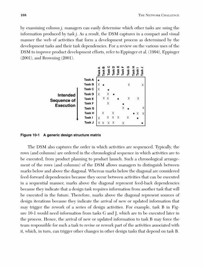
by examining column j, managers can easily determine which other tasks are using theinformation produced by task j. As a result, the DSM captures in a compact and visualmanner the web of activities that form a development process as determined by thedevelopment tasks and their task dependencies. For a review on the various uses of theDSM to improve product development efforts, refer to Eppinger et al. (1994), Eppinger(2001), and Browning (2001).
168 THE NETWORK CHALLENGE
Figure 10-1 A generic design structure matrix
The DSM also captures the order in which activities are sequenced. Typically, therows (and columns) are ordered in the chronological sequence in which activities are tobe executed, from product planning to product launch. Such a chronological arrange-ment of the rows (and columns) of the DSM allows managers to distinguish betweenmarks below and above the diagonal. Whereas marks below the diagonal are consideredfeed-forward dependencies because they occur between activities that can be executedin a sequential manner, marks above the diagonal represent feed-back dependenciesbecause they indicate that a design task requires information from another task that willbe executed in the future. Therefore, marks above the diagonal represent sources ofdesign iterations because they indicate the arrival of new or updated information thatmay trigger the rework of a series of design activities. For example, task B in Fig-ure 10-1 would need information from tasks G and J, which are to be executed later inthe process. Hence, the arrival of new or updated information to task B may force theteam responsible for such a task to revise or rework part of the activities associated withit, which, in turn, can trigger other changes in other design tasks that depend on task B.
13_0137011911_ch10.qxd 11/13/09 3:01 PM Page 168

Of course, some of these sources of design iterations can be removed by simply rese-quencing the DSM to minimize marks above the diagonal (Steward 1981; Eppinger etal. 1994), that is, making the development process as sequential as possible (see Figure10-2). By examining the resequenced (or optimally partitioned) DSM (see Figure 10-3),managers can identify the set of activities that could be executed in a serial fashion(sequential dependency) or those that are independent from each other (paralleldependency). More interesting, managers can also identify the set of design activitiesthat depend on each other in a cyclical manner (coupled dependency). Those are theinterdependent (or coupled) development activities that are likely to result in designiterations (Smith and Eppinger 1997a,b).
CHAPTER 10 • COORDINATION NETWORKS IN PRODUCT DEVELOPMENT 169
X
X
X
X X
X
X
X
X
X XXXX
X X X X XX
X X X
XX
X
XX
XX
X
A
B
C
D
E
F
G
H
I
J
K
L
A B C D E F G H I J K L
X
X
X
X
X
X X
X XX
X
X
X XX X
X XX
X
X X X
X
X
X
X
XX
X
B
C
A
K
L
J
F
I
E
D
H
G
B C A K L J F I E D H G
Swap rows and columnsto make a lowertriangular DSM
Figure 10-2 Partitioning a DSM into a low triangular DSM
X
X
X
X
X
X X
X XX
X
X
X XX X
X XX
X
X X X
X
X
X
X
XX
X
B
C
A
K
L
J
F
I
E
D
H
G
B C A K L J F I E D H G
Sequential
Parallel
Coupled
Figure 10-3 Partitioned DSM and types of task dependencies (Eppinger et al. 1994)
13_0137011911_ch10.qxd 11/13/09 3:01 PM Page 169
An Example from Automobile Design
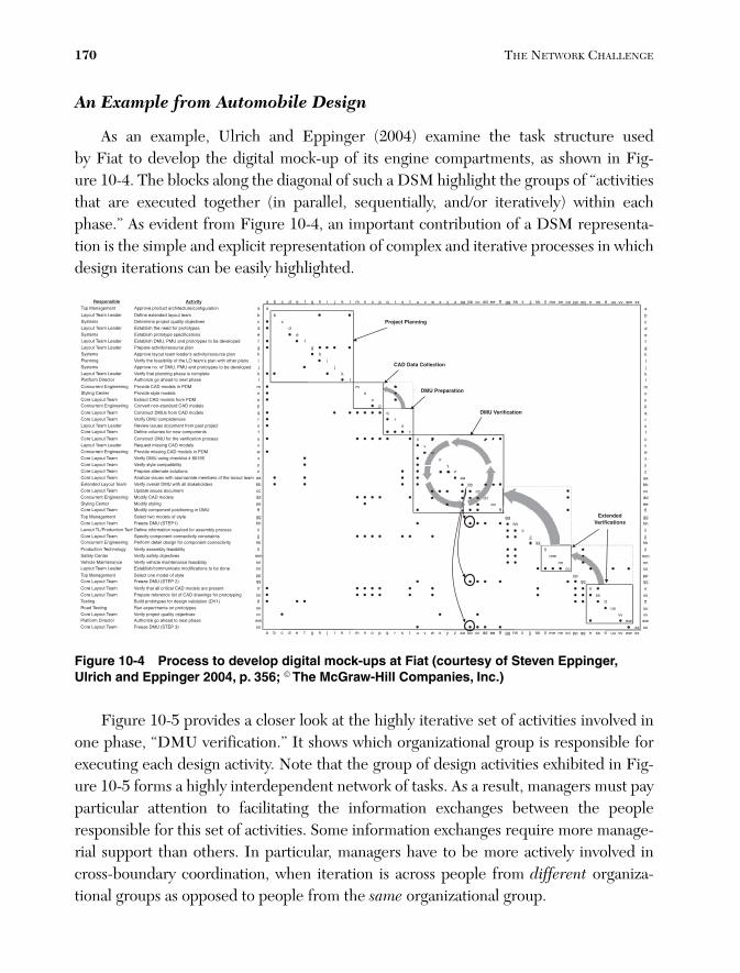
As an example, Ulrich and Eppinger (2004) examine the task structure used by Fiat to develop the digital mock-up of its engine compartments, as shown in Fig-ure 10-4. The blocks along the diagonal of such a DSM highlight the groups of “activitiesthat are executed together (in parallel, sequentially, and/or iteratively) within eachphase.” As evident from Figure 10-4, an important contribution of a DSM representa-tion is the simple and explicit representation of complex and iterative processes in whichdesign iterations can be easily highlighted.
170 THE NETWORK CHALLENGE
Responsible Activity a b c d e f g h i j k l m n o p q r s t u v w x y z aa bb cc dd ee ff gg hh ii jj kk ll mm nn oo pp qq rr ss tt uu vv ww xxTop Management Approve product architecture/configuration a a a
bbmaet tuoyal dednetxe enifeDredaeL maeT tuoyaL bcsevitcejbo ytilauq tcejorp enimreteDsmetsyS c cdsepytotorp rof deen eht hsilbatsEredaeL maeT tuoyaL d desnoitacificeps epytotorp hsilbatsEsmetsyS e e
Layout Team Leader Establish DMU, PMU and prototypes to be developed f f fgnalp ecruoser/ytivitca eraperPredaeL maeT tuoyaL g g
Systems Approve layout team leader's activity/resource plan h h hPlanning Verify the feasibility of the LO team's plan with other plans i i ISystems Approve no. of DMU, PMU and prototypes to be developed j j j
ketelpmoc si esahp gninnalp taht yfireVredaeL maeT tuoyaL k klesahp txen ot daeha og ezirohtuArotceriD mroftalP l l
mMDP ni sledom DAC edivorPgnireenignE tnerrucnoC m mnsledom elyts edivorPretneC gnilytS n noMDP morf sledom DAC tcartxEmaeT tuoyaL eroC o opsledom DAC dradnats-non trevnoCgnireenignE tnerrucnoC p p
qsledom DAC morf sUMD tcurtsnoCmaeT tuoyaL eroC q qrssenetelpmoc UMD yfireVmaeT tuoyaL eroC r r
Layout Team Leader Review issues document from past project s s ststnenopmoc wen rof semulov enifeDmaeT tuoyaL eroC t t
Core Layout Team Construct DMU for the verification process u u uvsledom DAC gnissim tseuqeRredaeL maeT tuoyaL v vwMDP ni sledom DAC gnissim edivorPgnireenignE tnerrucnoC w wx59108 # tsilkcehc gnisu UMD yfireVmaeT tuoyaL eroC x xyytilibitapmoc elyts yfireVmaeT tuoyaL eroC y yzsnoitulos etanretla eraperPmaeT tuoyaL eroC z z
Core Layout Team Analyze issues with appropriate members of the layout team aa aa aaExtended Layout Team Verify overall DMU with all stakeholders bb bb bb
cctnemucod seussi etadpUmaeT tuoyaL eroC cc ccddsledom DAC yfidoMgnireenignE tnerrucnoC dd ddeegnilyts yfidoMretneC gnilytS ee eeffUMD ni gninoitisop tnenopmoc yfidoMmaeT tuoyaL eroC ff ff
ggelyts fo sledom owt tceleStnemeganaM poT gggghh)1PETS( UMD ezeerFmaeT tuoyaL eroC hhhh
Layout TL/Production TechDefine information required for assembly process ii iiiiCore Layout Team Specify component connectivity constraints jj jjjjConcurrent Engineering Perform detail design for component connectivity kk kkkk
llytilibisaef ylbmessa yfireVygolonhceT noitcudorP ll llmmsevitcejbo ytefas yfireVretneC ytefaS mm mmnnytilibisaef ecnanetniam elcihev yfireVecnanetniaM elciheV nn nn
Layout Team Leader Establish/communicate modifications to be done oo oo oo
ppelyts fo ledom eno tceleStnemeganaM poT ppppqq)2 PETS( UMD ezeerFmaeT tuoyaL eroC qqqq
Core Layout Team Verify that all critical CAD models are present rr rr rrCore Layout Team Prepare reference list of CAD drawings for prototyping ss ss ssTesting Build prototypes for design validation (DV1) tt tt tt
uusepytotorp no stnemirepxe nuRgnitseT daoR uu uuvvsevitcejbo ytilauq tcejorp yfireVmaeT tuoyaL eroC vv vvwwesahp txen ot daeha og ezirohtuArotceriD mroftalP ww wwxx)3 PETS( UMD ezeerFmaeT tuoyaL eroC xx xx
a b c d e f g h j i k l m n o p q r s t u v w x y z aa bb cc dd ee ff gg hh ii jj kk ll mm nn oo pp qq rr ss tt uu vv ww xx
DMU Verification
CAD Data Collection
Extended Verifications
Project Planning
DMU Preparation
Figure 10-4 Process to develop digital mock-ups at Fiat (courtesy of Steven Eppinger,Ulrich and Eppinger 2004, p. 356; © The McGraw-Hill Companies, Inc.)
Figure 10-5 provides a closer look at the highly iterative set of activities involved inone phase, “DMU verification.” It shows which organizational group is responsible forexecuting each design activity. Note that the group of design activities exhibited in Fig-ure 10-5 forms a highly interdependent network of tasks. As a result, managers must payparticular attention to facilitating the information exchanges between the peopleresponsible for this set of activities. Some information exchanges require more manage-rial support than others. In particular, managers have to be more actively involved incross-boundary coordination, when iteration is across people from different organiza-tional groups as opposed to people from the same organizational group.
13_0137011911_ch10.qxd 11/13/09 3:01 PM Page 170

Figure 10-5 Iterative design tasks of FIAT’s “DMU verification” phase
In addition to identifying the subset of highly interdependent design activities thatare likely to generate design iterations, managers need to understand the specific natureand criticality of the task dependencies of these coupled activities. In the FIAT example,to manage the interdependent design tasks shown in Figure 10-5, managers needed toknow which specific engine components and CAD models were involved and how theywere connected to one another. In other words, executing the development processshown in Figures 10-4 and 10-5 depends largely on the specific configuration of theproduct under development, as well as the organization and experience of the peopleinvolved. Hence, to effectively manage design iterations in product development, man-agers have to examine the architecture and organizational structure associated with thedevelopment process. This approach illustrates how a network view of product and orga-nizational structures can improve the design and execution of complex product develop-ment processes. We now shift our view from the organizational processes to consideringthe products themselves.
Complex Products as Networks of Components
While complex products result from a network of interlinked design activities, asdiscussed previously, the products themselves can be seen as networks of intercon-nected components (Simon 1981). Product decomposition determines the architectureof the product, which is the way components interface with each other, so the productcan fulfill its functional requirements (Ulrich 1995, Ulrich and Eppinger 2004). More-over, the product architecture results in identifiable design interfaces between its vari-ous components (Henderson and Clark 1990; Ulrich 1995; Sosa, Eppinger, and Rowles2007a). These interfaces, in turn, are the main source of technical interdependencies
CHAPTER 10 • COORDINATION NETWORKS IN PRODUCT DEVELOPMENT 171
aa bb cc dd ee ff
aabbccddeeff
Core Layout TeamLayout Team LeaderConcurrent EngineeringCore Layout TeamCore Layout TeamCore Layout TeamCore Layout TeamExtended Layout TeamCore Layout TeamConcurret EngineeringStyling CenterCore Layout Team
Construct DMU for the verification processRequest missing CAD modelsProvide missing CAD models in PDMVerify DMU using checklist #80195Verify style compatibilityPrepare alternate solutionsAnalyze issues with appropriate members of the layout teamVerify overall DMU with all stakeholdersUpdate issues document Modify CAD modelsModify stylingModify component positioning in DMU
Responsible Activity
Interdependence within the same group
Interdependence across groups
uvwxyz
u v w x y z
uv
wx
yz
aabb
ccdd
ees
cd
w
13_0137011911_ch10.qxd 11/13/09 3:01 PM Page 171

between the design teams responsible for the development of such components, requir-ing coordination between them (Thompson 1967, Galbraith 1973).
Considering products as networks of components has resulted in two importantstreams of research in engineering design:
1. Product decomposition—Researchers decompose complex products usinggraphs, trees, and matrices (Michelena and Papalambros 1995; Chen, Ding, andLi 2005), paying particular attention to the identification of clusters of similarlydependent components (also called modules) to facilitate integration efforts dur-ing the design process (Pimmler and Eppinger 1994; Gershenson, Prasad, andAllamneni 1999; Sharman and Yassine 2004).
2. Design change propagation—Researchers also have used product-based DSMsto examine how design changes propagate through interconnected componentsduring the design process (Clarkson, Simons, and Eckert 2004; Eckert, Clarkson,and Zanker 2004). Because components are connected with each other to fulfillthe functional requirements of the product as a whole, engineering changes in onecomponent are likely to affect other components.
Although the two areas of research previously described have had a great influencein the way complex engineered products are architected and developed, the focus hasbeen on studying the product network as a whole rather than on structural properties ofthe components as a function of their connectivity with other components. To addressthis limitation, Sosa, Eppinger, and Rowles 2007a examine “modularity” of a compo-nent, defined as its level of independence from the other components. By doing so, weare able not only to quantify component modularity as a function of the lack of central-ity of the component with respect to other components in the product (Freeman 1979,Wasserman and Faust 1994), but also to relate how the modularity of product compo-nents relates to important design decisions such as component redesign.
Two important, and challenging, considerations when modeling complex products asnetworks of components are (1) defining the level of granularity at the node level; and(2) defining the various types of linkages between any two given components. To illus-trate how we have addressed these challenges, consider the architecture of a large com-mercial aircraft engine developed by Pratt & Whitney (Sosa, Eppinger, and Rowles2003, 2007a). Figure 10-6 shows both a cross-sectional diagram of the engine studiedand its network representation. According to our interviews with systems architects atthe research site, the engine was decomposed into eight subsystems, each of which was
172 THE NETWORK CHALLENGE
13_0137011911_ch10.qxd 11/13/09 3:01 PM Page 172

further decomposed into 5 to 10 components, for a total of 54 components. As a result,there are 54 nodes in the network map shown in Figure 10-6. The nodes are colored toillustrate the eight subsystems that composed the engine: Fan, Low-Pressure Compres-sor (LPC), High-Pressure Compressor (HPC), Combustion Chamber (CC), High-Pressure Turbine (HPT), Low-Pressure Turbine (LPT), Mechanical Components (MC),and External and Controls (EC). Because this was the third engine derived from thesame basic engine design, the product decomposition into subsystems and componentswas well understood by our informants, and corresponded with the level of granularityused to establish the organizational structure that designed each of the 54 components.Using a higher level of granularity at the subsystem level would have resulted in a net-work of only eight nodes corresponding to the eight subsystems of the engine, whileusing a lower level of granularity would have resulted in several hundreds (perhapsthousands) of parts whose individual functionality did not correspond with any impor-tant functional requirement of the engine. Using the engine component, also calledengineering chunks (Ulrich and Eppinger 1994), as the unit of analysis allowed us torepresent the engine based on individual elements associated with important functionalrequirements with dedicated cross-functional teams responsible for their design anddevelopment.
CHAPTER 10 • COORDINATION NETWORKS IN PRODUCT DEVELOPMENT 173
Figure 10-6 Cross-sectional view and network diagram of the PW4098 aircraft engine
After documenting the general decomposition of the product, we identified the net-work of design dependencies among the 54 components of the engine. We distinguishedfive types of design dependencies to define the design interfaces (or linkages) of thephysical components (see Table 10-1). In addition, we used a five-point scale to capturethe level of criticality of each dependency for the overall functionality of the componentin question (see Table 10-2), which captures positive or negative design dependenciesbetween components, those that either enable or hinder the component’s functionality
13_0137011911_ch10.qxd 11/13/09 3:01 PM Page 173

(Jarratt, Clarkson, and Eckert 2004). We consider three levels of criticality: indifferent(0), weak (-1,+1), and strong (-2,+2), because we assume that negative component inter-actions indicate equally important design dependencies to be addressed as positive ones.For additional details on metrics and linkages between product components in complexproducts, refer to Sosa, Eppinger, and Rowles (2003, 2007a).
TABLE 10-1 Types of Design Dependency
Dependency Description
Spatial Functional requirement related to physical adjacency for alignment, orientation, serviceability, assembly, or weight
Structural Functional requirement related to transferring loads or containment
Material Functional requirement related to transferring airflow, oil, fuel, or water
Energy Functional requirement related to transferring heat, vibration, electric, or noise energy
Information Functional requirement related to transferring signals or controls
TABLE 10-2 Level of Criticality of Design Dependencies
Measure Description
(+2) Dependency is necessary for functionality.
(+1) Dependency is beneficial but not absolutely necessary for functionality.
(0) Dependency does not affect functionality.
(-1) Dependency causes negative effects but does not prevent functionality.
(-2) Dependency must be prevented to achieve functionality.
Those components that are less connected to other engine components are moremodular because they have more degrees of freedom to fulfill their functional require-ments independently of the state of other engine components. Less modular compo-nents, which are more integrally connected (via nonstandardized interfaces) to otherengine components, are more dependent on other components to fulfill their functionalrequirements. Interestingly, components in complex products exhibit large variation interms of their interconnectivity within the product. Figure 10-7 shows two engine com-ponents with extreme levels of component modularity.
174 THE NETWORK CHALLENGE
13_0137011911_ch10.qxd 11/13/09 3:01 PM Page 174

Figure 10-7 Two engine components with the low and high levels of connectivity
Modularity is important because managers should consider the connectivity of com-ponents with other components when making important design decisions such as out-sourcing or redesigning product components. For example, we found that thosecomponents of the engine that were more (directly and indirectly) connected to “trans-mit forces” (an important engine functional requirement) to other components were theones that exhibited higher levels of component redesign, whereas those componentsthat were more connected due to spatial consideration (an important design constraint)were the ones that exhibited lower levels of component redesign. Hence, the modularityof a component in a complex product can be associated with both high and low levels ofcomponent redesign. Managers can use the knowledge of linkages among componentsto propagate design decisions or to avoid redesigning some components to preventpropagating design constraints that could disrupt certain functional requirements of theproduct (Baldwin and Clark 2000; Sosa, Eppinger, and Rowles 2007a).
In addition to understanding how process networks and networks of componentscome together in designing complex products such as an airplane or automobile, managersalso have to understand how the organization actually coordinates the technical interfacesbetween the components they design (Allen 1977), as considered in the next section.
The Informal Communication Network of Design Teams
Communication among design teams working on specific product components iscrucial to success, as can be illustrated by two cases. In 1999, the Ford Explorer wentfrom being the number one sport utility vehicle (SUV) sold in USA to the least desiredone due to quality problems associated with the suspension system of the Ford Explorer
CHAPTER 10 • COORDINATION NETWORKS IN PRODUCT DEVELOPMENT 175
13_0137011911_ch10.qxd 11/13/09 3:01 PM Page 175

and the design of its Bridgestone/Firestone tires. Ford and Bridgestone/Firestone lostbillions of dollars after their failure to coordinate the vehicle design of the Ford Explorerwith the design of its tires (Pinedo, Sehasdri, and Zemel 2000). Similarly, Airbus’s devel-opment of the A380 “superjumbo” suffered major delays and cost overruns because oflate-emerging incompatibilities in the design of the electrical harnesses of various sec-tions of the plane’s fuselage. In this case, the electrical harnesses team in Germany andits counterpart team in France, which were responsible for different sections of thefuselage, were not properly communicating about their design interface specifications(Gumbel 2006). These mistakes likely contributed to the resignation of CEOs and theloss of other senior executives’ jobs at both Ford and Airbus.
Although attention to technical interfaces is crucial for successful product develop-ment, teams typically ignore (or pay marginal attention to) a number of interfaces duringthe development process (Sosa, Eppinger, and Rowles 2004). Some level of neglect isperhaps unavoidable given the cognitive and resource limitations of teams (Simon1947). Although lack of attention to noncritical or standardized interfaces may not besignificant (Sosa, Eppinger, and Rowles 2004), the neglect of critical interfaces can haveserious negative consequences (Henderson and Clark 1990).
To address this challenge, we need to examine both the architecture of the productand the informal organizational structure. The technical interfaces among product com-ponents define the coordination requirements, and technical communication amongdesign teams constitutes one of the primary coordination mechanisms. Figure 10-8shows a network of technical interfaces between four components and a network oftechnical communications between six teams, four of which are in charge of designingthese components and two others of which are in charge of integration activities (Sosa,Gargiulo, and C. Rowles 2007).
176 THE NETWORK CHALLENGE
Figure 10-8 Hypothetical networks of components and design teams
13_0137011911_ch10.qxd 11/13/09 3:01 PM Page 176

By superimposing the maps of product interfaces onto the technical communicationstructure, we can understand where communications links are missing or may be unnec-essary. Managers can identify not only the technical interfaces that are matched by tech-nical team interactions (links a, b, and c) but also the cases of mismatches of componentinterfaces and team interactions. There are two types of mismatches: unmatched inter-faces, also called unattended interfaces, such as link d in Figure 10-8, in which a techni-cal interface is not attended by technical communication between corresponding designteams; and unmatched interactions such as link e in Figure 10-8, in which teams com-municate for technical reasons even though the system architects had not identifiedtechnical interfaces between their components. Finally, there are also external interac-tions that occur when teams that are not directly responsible for the design of a compo-nent interact with teams designing components. This may be the case with teams thatare in charge of overseeing the integration among different aspects of the design but arenot responsible for designing any specific component, as is the case with teams 5 and 6in Figure 10-8.
Most of the complex development projects we have studied in the automobile andaerospace industries exhibit this quasi-direct mapping of product architecture and orga-nizational structure; that is, component X is designed by team X with a few system inte-gration teams in charge of evaluating product-level requirements (for example, the fueleconomy of an automobile or the weight requirements of an airplane). In some projectssuch as software development, however, mapping the architecture and organization isfar from one-to-one. (In such cases, we can still adapt the approach described in thischapter; refer to Sosa 2008 for details.)
Although Figure 10-8 shows a simple example, overlaying the actual maps of productand organizational interfaces for a product such as the Pratt & Whitney engine we havestudied is a daunting task (see Figure 10-9). As a result, we use a matrix representation tocompare complex product and organizational networks, as illustrated in Figure 10-10.
CHAPTER 10 • COORDINATION NETWORKS IN PRODUCT DEVELOPMENT 177
Figure 10-9 Network maps of product and organizational networks of the PW4098 engine
13_0137011911_ch10.qxd 11/13/09 3:01 PM Page 177
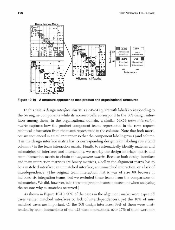
Figure 10-10 A structure approach to map product and organizational structures
In this case, a design interface matrix is a 54×54 square with labels corresponding tothe 54 engine components while its nonzero cells correspond to the 569 design inter-faces among them. In the organizational domain, a similar 54×54 team interactionmatrix captures how the product component teams represented in the rows requesttechnical information from the teams represented in the columns. Note that both matri-ces are sequenced in a similar manner so that the component labeling row i (and columni) in the design interface matrix has its corresponding design team labeling row i (andcolumn i) in the team interaction matrix. Finally, to systematically identify matches andmismatches of interfaces and interactions, we overlay the design interface matrix andteam interaction matrix to obtain the alignment matrix. Because both design interfaceand team interaction matrices are binary matrices, a cell in the alignment matrix has tobe a matched interface, an unmatched interface, an unmatched interaction, or a lack ofinterdependence. (The original team interaction matrix was of size 60 because itincluded six integration teams, but we excluded these teams from the comparisons ofmismatches. We did, however, take these integration teams into account when analyzingthe reasons why mismatches occurred.)
As shown in Figure 10-10, 90% of the cases in the alignment matrix were expectedcases (either matched interfaces or lack of interdependences), yet the 10% of mis-matched cases are important. Of the 569 design interfaces, 39% of them were unat-tended by team interactions; of the 423 team interactions, over 17% of them were not
178 THE NETWORK CHALLENGE
13_0137011911_ch10.qxd 11/13/09 3:01 PM Page 178

associated with design interfaces. Sosa, Eppinger, and Rowles (2004) analyzed the prod-uct and organizational factors associated with the systematic occurrence of these mismatches and found that both interface criticality and group boundary matter signifi-cantly. Most of the unattended interfaces uncovered in the alignment matrix were low-criticality interfaces. The unmatched interfaces and interactions between teamboundaries were at higher risk of being both unattended by team interactions andunidentified by system architects. Sosa, Eppinger, and Rowles (2007b) discuss the man-agerial implications of this approach in more detail.
By taking a closer look at design interfaces for specific components, we observedthat some components had 100% of their design interfaces attended by team interac-tions while others exhibited less than 40% of their interfaces attended. Why are someteams better than others at attending the technical interfaces of the components theydesign? Is it because of attributes of the components they design, or because of the struc-ture of the communication networks with other teams in the organization, or both? Sosa,Gargiulo, and C. Rowles (2007) found that after controlling for component and teamattributes, both the connectivity of product components and the structure of the com-munication network of design teams matter. Interestingly, these network propertiesmatter in different ways depending on whether the focal team acts as a provider orreceiver of technical information.
Components appear to have an impact because teams working on highly indirectlyconnected components have trouble paying attention to technical requests from othersbecause such teams are the ones more likely to suffer excessive and unforeseeable work-load due to heavy design iterations. The team’s communication network structures alsohave an effect because, on one hand, teams with sparse communication networks weremore likely to search and acquire the technical information about the interfaces of thecomponents they design, and, on the other hand, those teams that were surrounded by amore cohesive communication network structure were the ones that exhibited highercapability to attend the technical requests from other design teams in the network. (Thisis presumably because such teams enjoyed the benefits of the collaborative environmentassociated with close and cohesive networks.)
CHAPTER 10 • COORDINATION NETWORKS IN PRODUCT DEVELOPMENT 179
13_0137011911_ch10.qxd 11/13/09 3:01 PM Page 179

Conclusions and Future Directions
As Simon (1981) suggested, complex systems are difficult to understand because thebehavior of the whole depends in nontrivial ways on how its elements interact. Thischapter has outlined how a network view of processes, products, and organizations can help us understand how complex product development systems draw together components that form complex systems such as automobiles or aircraft engines. By con-sidering processes not as a sequential set of activities but instead as a web of tasks, someof which can be highly interdependent, we have uncovered the reason design iterationsoccur. By modeling complex products as networks of interconnected components, wehave learned how to cluster components into modules in a more efficient way to makecomplex systems nearly decomposable systems (Simon 1981). In addition, by taking anetwork approach to analyzing complex products, we can then consider structural prop-erties of product components that are defined by the patterns of technical interfaceswith other components. Finally, by mapping the network of components that form aproduct with the communication network of teams that design such components, wehave been able to evaluate systematically why some interfaces are at higher risk of beingunattended than others.
Only by taking a network perspective have we been able to uncover these findingsand insights. Yet there is more to learn. Two promising areas in product development thatwould certainly benefit from a network perspective are product-organizational dynamicsand innovation networks. To study the coevolution of product and organizational struc-tures, our current research efforts focus on examining open source software development(Sosa, Browning, and Mihm 2007). One of the advantages of studying the architecture ofsoftware products is that their architecture is relatively easy to capture because it is prop-erly codified in their source code (Sangal et al. 2005; MacCormack, Rusnack, and Bald-win 2006). In addition, software products are complex and fast-evolving, which makesthem our ideal “fruit flies” to investigate how complex systems evolve over time.
Understanding creativity is imperative for effective innovation management. Cre-ativity is no longer considered an individual attribute but a social activity, yet we are justbeginning to understand the role of social networks in the creative process (Fleming,Mingo, and Chen 2007; Sosa 2007). Which attributes of the knowledge exchanged inorganizational networks like the ones discussed in this chapter influence creative out-comes? Are more talkative teams more likely to generate more novel and useful ideasthan less talkative teams? These are some of the questions innovation managers need toaddress as they also embark on the challenge of understanding the social networks theyare managing.
180 THE NETWORK CHALLENGE
13_0137011911_ch10.qxd 11/13/09 3:01 PM Page 180

Finally, as pointed out by Nambisan and Sawhney in Chapter 9, “Network-CentricInnovation: Four Strategies for Tapping the Global Brain,” different models for net-work-centric innovation require different types of coordination and communication.Whether the process is more centralized (such as the Orchestra model) or more decen-tralized (such as the Global Bazaar model) will determine the type of interfaces that areneeded in the network of design teams, the level of creativity that is desired, and thetypes of communication flows.
As product development increasingly depends on networks of design teams, net-work thinking will be a useful capability for managers in building more successful prod-uct development organizations. The frameworks presented in this chapter offer valuabletools for understanding and improving how these networks are structured, communi-cate, and evolve.
References
Allen, T. J. 1977. Managing the Flow of Technology. Cambridge, MA: MIT Press.
Baldwin, C. Y., and K. B. Clark. 2000. Design Rules: Volume 1: The Power of Modularity.Cambridge, MA: MIT Press.
Browning, T. R. 2001. Applying the design structure matrix to system decompositionand integration problems: A review and new directions. IEEE Transactions on Engineering Management 48 (3), 292-306.
Chen, L., Z. Ding, and S. Li. 2005. A formal two-phase method for decomposition ofcomplex design problems. ASME J. Mech. Des. 127, 184-195.
Clarkson, P. J., C. S. Simons, and C. M. Eckert. 2004. Predicting change propagation incomplex design. ASME Journal of Mechanical Design 126 (5), 765-797.
Eckert, C. M., P. J. Clarkson, and W. Zanker. 2004. Change and customization in com-plex engineering domains. Research in Engineering Design 15 (1), 1-21.
Eppinger, S. D. 2001. Innovation at the speed of information. Harvard Business Review.
Eppinger, S. D., D. E. Whitney, R. P. Smith, and D. A. Gebala. 1994. A model-basedmethod for organizing tasks in product development. Research in EngineeringDesign 6 (1), 1-13.
Fleming, L., S. Mingo, and D. Chen. 2007. Brokerage and collaborative creativity.Administrative Science Quarterly 52: 443-475
CHAPTER 10 • COORDINATION NETWORKS IN PRODUCT DEVELOPMENT 181
13_0137011911_ch10.qxd 11/13/09 3:01 PM Page 181

Freeman, L. 1979. Centrality in social networks. Conceptual clarification. Social Networks 1, 215-239.
Galbraith, J. R. 1973. Designing Complex Organizations. Reading, MA: Addison-WesleyPublishing.
Gershenson, J. K., G. J. Prasad, and S. Allamneni. 1999. Modular product design: A life-cycle view. Journal of Integrated Design and Process Science 3 (4), 13-26
Gumbel, P. 2006. Trying to untangle wires. Time, October 16 (European edition), 36-37.
Henderson, R., and K. Clark. 1990. Architectural innovation: The reconfiguration ofexisting product technologies and the failure of established firms. AdministrativeScience Quarterly 35 (1), 9-30.
Jarratt, T., J. Clarkson, and C. Eckert. 2005. Engineering Change. In Design ProcessImprovementA Review of Current Practices, 266-285.
MacCormack, A., J. Rusnack, and C. Baldwin. 2006. Exploring the structure of complexsoftware designs: An empirical study of open source and proprietary code. Manage-ment Science 52 (7), 1015-1030.
Michelena, N., and P. Y. Papalambros. 1995. A network reliability approach to optimaldecomposition of design problems. ASME Journal of Mechanical Design 117 (3),433-440.
Mihm, J., C. Loch, and A. Huchzermeier. 2003. Problem-solving oscillations in complexengineering projects. Manag. Sci. 46 (6), 733-750.
Pimmler, T. U., and S. D. Eppinger. 1994. Integration analysis of product decomposi-tions. ASME Conference on Design Theory and Methodology, in Minneapolis, MN,343-351.
Pinedo, M., S. Sehasdri, and E. Zemel. 2000. The Ford-Firestone case. Teaching case.Department of Information, Operations, and Management Sciences, Stern Schoolof Business, NYU.
Pisano, G. 1996. BMW: The seven series project. HBS case 9-692-083.
Sangal, N., E. Jordan, V. Sinha, and D. Jackson. 2005. Using dependency models tomanage complex software architecture, Proceedings of the 20th Annual ACM SIG-PLAN Conference on Object Oriented Programming, Systems, Languages, andApplications, in San Diego, CA.
182 THE NETWORK CHALLENGE
13_0137011911_ch10.qxd 11/13/09 3:01 PM Page 182

Sharman, D., and A. Yassine. 2004. Characterizing complex products architectures. Systems Engineering 7 (1), 35-60.
Simon, H. A. 1947. Administrative Behavior: A Study of Decision-making Processes inAdministrative Organizations. Chicago, IL: Macmillan.
Simon, H. A. 1981. The Science of the Artificial. 2nd ed. Cambridge, MA: MIT Press.
Smith, R. P., and S. D. Eppinger. 1997a. A predictive model of sequential iteration inengineering design. Manag. Sci. 43 (3) 276-293.
Smith, R. P., and S. D. Eppinger. 1997b. Identifying controlling features of engineeringdesign iteration. Manag. Sci. 43 (8) 1104-1120.
Sosa, M. E. 2007. Where do creative interactions come from? The role of tie contentand social networks. INSEAD working paper 2007/49/TOM.
Sosa, M. E. 2008. A structured approach to predicting and managing technical interac-tions in software development. Research in Engineering Design 19(1) 47-70.
Sosa, M. E., T. Browning, and J. Mihm. 2007. Studying the dynamics of the architectureof software products. Proceedings of the 19th ASME Design Theory and Methodol-ogy Conference.
Sosa, M. E., S. D. Eppinger, and C. M. Rowles. 2003. Identifying modular and integra-tive systems and their impact on design team interactions. ASME Journal of Mech.Design 125 (2), 240-252.
Sosa, M. E., S. D. Eppinger, and C. M. Rowles. 2004. The misalignment of productarchitecture and organizational structure in complex product development. Man-agement Science 50 (12), 1674-1689.
Sosa, M. E., S. D. Eppinger, and C. M. Rowles. 2007a. A network approach to definemodularity of components in complex products. ASME Journal of MechanicalDesign 129 (11), 1118-1129.
Sosa, M. E., S. D. Eppinger, and C. M. Rowles. 2007b. Are your engineers talking to oneanother when they should? Harvard Business Review, November.
Sosa, M. E., M. Gargiulo, and C. Rowles. 2007. Component connectivity, team networkstructure, and the attention to technical interfaces in complex product development.INSEAD working paper 68/TOM/OB.
Steward, D. 1981. The design structure matrix: A method for managing the design of complex systems. IEEE Transactions on Engineering Management EM-28 (3),71-74.
CHAPTER 10 • COORDINATION NETWORKS IN PRODUCT DEVELOPMENT 183
13_0137011911_ch10.qxd 11/13/09 3:01 PM Page 183

Thompson, J. D. 1967. Organizations in Action. New York: McGraw-Hill.
Ulrich, K. T. 1995. The role of product architecture in the manufacturing firm. Res. Policy. 24, 419-440.
Ulrich, K. T., and S. D. Eppinger. 2004. Product Design and Development. 3rd ed. NewYork: McGraw Hill.
Wasserman, S., and K. Faust. 1994. Social Network Analysis. New York: CambridgeUniversity Press.
184 THE NETWORK CHALLENGE
13_0137011911_ch10.qxd 11/13/09 3:01 PM Page 184

CHAPTER 10 • COORDINATION NETWORKS IN PRODUCT DEVELOPMENT 185
13_0137011911_ch10.qxd 11/13/09 3:01 PM Page 185

186 THE NETWORK CHALLENGE
13_0137011911_ch10.qxd 11/13/09 3:01 PM Page 186

CHAPTER 10 • COORDINATION NETWORKS IN PRODUCT DEVELOPMENT 187
13_0137011911_ch10.qxd 11/13/09 3:01 PM Page 187