122883ah-one file june,21,02 - skyjack inc manual... · skyjack, inc. warrants each new work...
TRANSCRIPT
Engin
eP
ow
ered
SJ-6
00, 8
00 &
1000 Serie
s
For Service please call .....................................................................800 275-9522Skyjack Inc. Service Center, 3451 Swenson Ave., St. Charles, IL. 60174 ... FAX 630 262-0006For Parts in North America and Asia please call .................................... 800 965-4626Skyjack Inc. Parts Center, 3451 Swenson Ave., St. Charles, IL. 60174 ............. FAX 888 782-4825For Parts & Service in Europe please call ....................................................31 297 255 526Skyjack Europe Communicatieweg 29, 3641 SG Mijdrecht Netherlands .............FAX 31 297 256 948
122883AH Printed in Canada June 2002
OPERATING MANUALThis manual MUST be kept and stored with the aerial platform at all times.
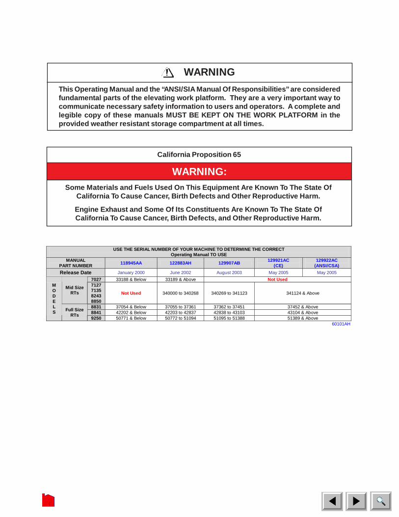
USE THE SERIAL NUMBER OF YOUR MACHINE TO DETERMINE THE CORRECT Operating Manual TO USE
MANUAL PART NUMBER 118945AA 122883AH 129907AB
129921AC (CE)
129922AC (ANSI/CSA)
Release Date January 2000 June 2002 August 2003 May 2005 May 2005
7027 33188 & Below 33189 & Above Not Used
Mid Size RTs
7127 7135 8243 8850
Not Used 340000 to 340268 340269 to 341123 341124 & Above
8831 37054 & Below 37055 to 37361 37362 to 37451 37452 & Above 8841 42202 & Below 42203 to 42837 42838 to 43103 43104 & Above
M O D E L S Full Size
RTs 9250 50771 & Below 50772 to 51094 51095 to 51388 51389 & Above
60101AH
WARNING
This Operating Manual and the “ANSI/SIA Manual Of Responsibilities” are consideredfundamental parts of the elevating work platform. They are a very important way tocommunicate necessary safety information to users and operators. A complete andlegible copy of these manuals MUST BE KEPT ON THE WORK PLATFORM in theprovided weather resistant storage compartment at all times.
WARNING:Some Materials and Fuels Used On This Equipment Are Known To The State Of
California To Cause Cancer, Birth Defects and Other Reproductive Harm.
Engine Exhaust and Some Of Its Constituents Are Known To The State OfCalifornia To Cause Cancer, Birth Defects, and Other Reproductive Harm.
California Proposition 65
Page 3SJ 600, 800 & 1000 Series122883AH May 2002
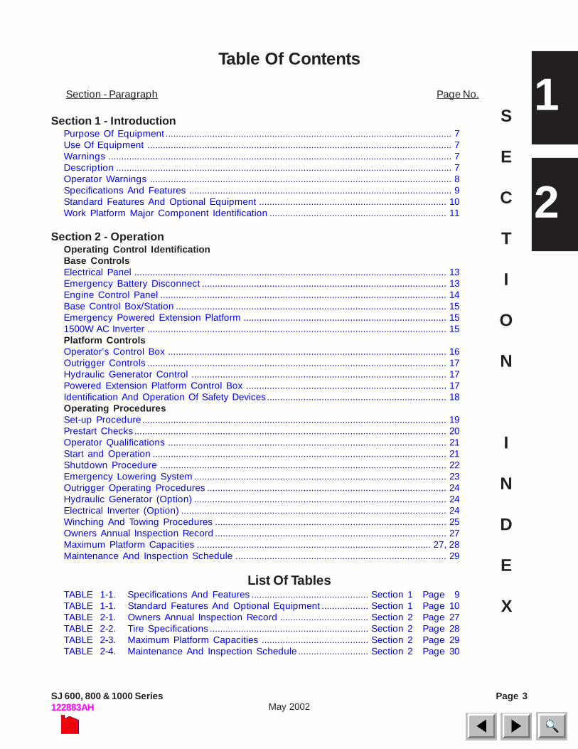
Table Of Contents
S
E
C
T
I
O
N
I
N
D
E
X
Section - Paragraph Page No.
Section 1 - IntroductionPurpose Of Equipment .............................................................................................................. 7Use Of Equipment ..................................................................................................................... 7Warnings .................................................................................................................................... 7Description ................................................................................................................................. 7Operator Warnings .................................................................................................................... 8Specifications And Features ..................................................................................................... 9Standard Features And Optional Equipment ........................................................................ 10Work Platform Major Component Identification .................................................................... 11
Section 2 - OperationOperating Control IdentificationBase ControlsElectrical Panel ........................................................................................................................ 13Emergency Battery Disconnect .............................................................................................. 13Engine Control Panel .............................................................................................................. 14Base Control Box/Station ........................................................................................................ 15Emergency Powered Extension Platform .............................................................................. 151500W AC Inverter ................................................................................................................... 15Platform ControlsOperator’s Control Box ........................................................................................................... 16Outrigger Controls ................................................................................................................... 17Hydraulic Generator Control .................................................................................................. 17Powered Extension Platform Control Box ............................................................................. 17Identification And Operation Of Safety Devices ..................................................................... 18Operating ProceduresSet-up Procedure ..................................................................................................................... 19Prestart Checks ........................................................................................................................ 20Operator Qualifications ........................................................................................................... 21Start and Operation ................................................................................................................. 21Shutdown Procedure .............................................................................................................. 22Emergency Lowering System ................................................................................................. 23Outrigger Operating Procedures ............................................................................................ 24Hydraulic Generator (Option) ................................................................................................. 24Electrical Inverter (Option) ...................................................................................................... 24Winching And Towing Procedures ......................................................................................... 25Owners Annual Inspection Record ......................................................................................... 27Maximum Platform Capacities .......................................................................................... 27, 28Maintenance And Inspection Schedule ................................................................................. 29
List Of TablesTABLE 1-1. Specifications And Features ............................................. Section 1 Page 9TABLE 1-1. Standard Features And Optional Equipment .................. Section 1 Page 10TABLE 2-1. Owners Annual Inspection Record .................................. Section 2 Page 27TABLE 2-2. Tire Specifications ............................................................. Section 2 Page 28TABLE 2-3. Maximum Platform Capacities ......................................... Section 2 Page 29TABLE 2-4. Maintenance And Inspection Schedule ........................... Section 2 Page 30
1
2

Page 4 SJ 600, 800 & 1000 Series122883AHMay 2002
WARNING
OPERATOR SAFETY REMINDERSThe National Safety Council reminds us that most accidents are caused by the failure of some individuals tofollow simple and fundamental safety rules and precautions. Common sense dictates the use of protectiveclothing when working on or near machinery. Use appropriate safety devices to protect your eyes, ears,hands, feet and body.
You, as a careful operator, are the best insurance against an accident. Therefore, proper usage of this workplatform is mandatory. The following pages of this manual should be read and understood completely beforeoperating the work platform. Any modifications from the original design are strictly forbidden without writtenpermission from SKYJACK, Inc.
ANSI/SIA (United States)You are required by the current ANSI/SIA A92.6 standards to read and understand YOURRESPONSIBILITIES in the Manual Of Responsibilities before you use or operate this work platform.
CSA (Canada) and CE (Europe)You are required to conform to national health and safety regulations applicable to the operation of thiselevating work platform.
FAILURE TO COMPLY with your REQUIRED RESPONSIBILITIES in the use and operation of thework platform could result in DEATH OR SERIOUS INJURY!
DANGER
ELECTROCUTION HAZARD
THIS MACHINE IS NOT INSULATED. MAINTAIN SAFE CLEARANCES FROM ELECTRICAL POWER LINES AND APPARATUS. YOU MUST ALLOW FOR PLATFORM SWAY, ROCK OR SAG. THIS WORK PLATFORM DOES NOT PROVIDE PROTECTION FROM CONTACT WITH OR PROXIMITY TO AN ELECTRICALLY CHARGED CONDUCTOR.
Minimum Safe Approach Distance ANSI/SIA A92.6-1999 &
CSA CAN3-B354.2&.3-M82 Requirements CE Guidance Note
“Avoidance of danger from Overhead Lines” Voltage Range Minimum Safe Approach Distance
(Phase to Phase) Feet Meters 0 To 300V Avoid Contact
Over 300V to 50KV 10 3.05 Over 50KV to 200KV 15 4.60
Over 200KV to 350KV 20 6.10 Over 350KV to 500KV 25 7.62 Over 500KV to 750KV 35 10.67
Over 750KV to 1000KV 45 13.72
These machines should not operate within 15M of overhead lines suspended from steel towers.
These machines should not operate within 9M of overhead lines suspended from wooden poles.
FAILURE TO AVOID THIS HAZARD WILL RESULT IN DEATH OR SERIOUS INJURY!

Page 5SJ 600, 800 & 1000 Series122883AH May 2002
SERVICE POLICY AND WARRANTYSKYJACK, Inc. warrants each new work platform to be free of defective parts and workmanship during the first12 months. Refer to Warranty Statement on Page 6 for details.
NOTESKYJACK, Inc. is continuously improving and expanding product features on it’s equipment: therefore,specifications and dimensions are subject to change without notice.
This Safety Alert Symbol Means Attention!
Become Alert! Your Safety Is Involved.
The Safety Alert Symbol identifies important safety messages on machines, safety signs, in manuals, or else-where. When you see this symbol, be alert to the possibility of personal injury or death. Follow the instructionsin the safety message.
SCOPE OF THIS MANUALThis manual applies to the ANSI/SIA, CSA and CE versions of the SJ-600, SJ-800 and SJ-1000 Series workplatform models listed in Table 1-1. Equipment identified with “ANSI/SIA” meets the ANSI/SIA-A92.6-1999 standards.Equipment identified with “CSA” meets the CAN3-B354.2 & .3-M82 standards. Equipment identified with “CE”meets the requirements for the European countries, i.e. Machinery Directive 89/392/EEC and EMC Directive 89/336/EEC and the corresponding EN standards.
DO NOT OPERATE THIS EQUIPMENT WITHOUT PROPERAUTHORIZATION AND TRAINING. DEATH OR SERIOUSINJURY COULD RESULT FROM IMPROPER USE OF THIS
EQUIPMENT!
Page 6 SJ 600, 800 & 1000 Series122883AHMay 2002
SKYJACK, Inc. warrants each new work platform tobe free of defective parts and workmanship. Duringthe first full year, labor and replacement parts will beprovided by the local authorized Skyjack dealerwithout charge. For the following 48 months,structural components found to be defective will bereplaced or repaired at no charge.
A warranty registration card is supplied with eachwork platform. The warranty is only effective whenthe warranty card has been completed and returnedto Skyjack within 15 days from the time of billing.When work platforms are put into stock, the warrantyperiod does not start until the work platform has beenshipped to the dealers customer. If a unit is put intoservice and no warranty card has been mailed toSkyjack, Inc., the warranty period will commence 15days from the date the dealer was invoiced for thework platform.
All warranty claims are subject to approval bySkyjack’s Service Department. Skyjack, Inc. reservesthe right to limit or adjust claims with regard todefective parts, labor or travel time based on usualand customary guidelines. Parts purchased fromsources other than Skyjack will not be covered underthis warranty. Misuse or improper operation, lack ofnormal maintenance and inspections as outlined inthis Operating/Maintenance and Parts Manual,alterations to original design and/or components oraccidents will void all warranty. Batteries are notcovered by this warranty.
The above mentioned warranty statement is exclusiveand no other warranty whether written, oral or impliedshall apply. Skyjack excludes any implied warranty ofmerchantability and fitness and accepts no liability forconsequential damages or for other negligence.
WARRANTY PROCEDURES
The selling distributor or authorized dealer shall beresponsible for the complete handling of customerclaims under this warranty. Here’s what to do:
1. When a customer files a claim under thiswarranty, contact Skyjack’s Service Department toverify warranty coverage. NOTE: The complete serialnumber of the work platform is required to verify theclaim.
2. When Skyjack’s Service Department verifieswarranty coverage, they will also issue an RA (ReturnAuthorization) number for the return of any defectivecomponent(s). All items over $25.00 in value must bereturned to Skyjack, Inc.
WARRANTY STATEMENT3. Fill out a Warranty Claim Form from dealer’ssupply of claim forms. Then notify Skyjack’s ServiceDepartment of the warranty claim number on theform used.
4. The distributor/dealer should then file a warrantyclaim with Skyjack, Inc. describing the nature of thedefect, probable cause, work performed, travelhours, and labor hours listed separately. Warrantylabor will be paid at a rate of $42.00 per hour. Thetravel allowance will be paid at the same hourly ratewithin the dealers specified territory, limited to amaximum of four (4) hours. If a part has serviceablecomponents, PLEASE replace the bad component.For instance, if you have a bad switch on a controller,please replace the switch. Hydraulic cylinders shouldbe resealed, unless they are damaged beyond repair.Engine failures should be directed to your localengine distributor and covered by the manufacturerswarranty. Skyjack will accommodate you and yourlabor. Labor rates and travel allowances are subjectto change without notice.
5. Warranty claims must be received by Skyjackwithin 15 working days from the date of the repair.Warranty claims received with insufficient informationwill be returned for correction or completion.
6. Materials returned for warranty inspection musthave the following procedures:
A. Carefully packaged to prevent additionaldamage during shipping.
B. Drained of all contents and all open portscapped or plugged.
C. Shipped in a container tagged or marked withthe RA number.
D. Shipped PREPAID. Any item(s) returned forwarranty by any other means may be refusedand returned unless prior approval from Skyjackis obtained.
E. Items shipped to the dealer will be sent freightprepaid and added to the invoice.
Failure to comply with the above procedures maydelay approval and processing of the warranty claimand could result in the denial of a warranty claim.Skyjack’s dealer’s accounts must be kept current inorder to approve and issue warranty credits. Skyjackreserves the right to withhold issuance of warrantycredits to a dealer if their account is not in goodstanding. This is subject to change without priornotice.
SECTION 1, Page 7SJ 600, 800 & 1000 Series122883AH May 2002
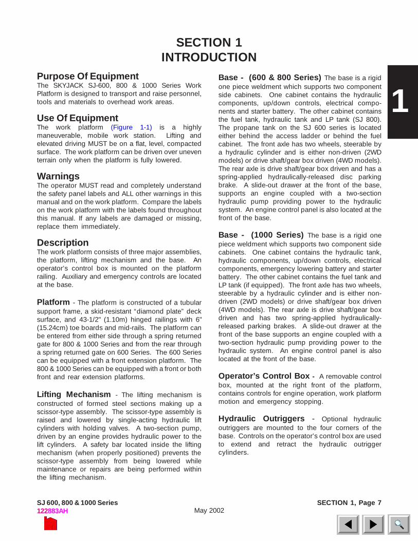
Purpose Of EquipmentThe SKYJACK SJ-600, 800 & 1000 Series WorkPlatform is designed to transport and raise personnel,tools and materials to overhead work areas.
Use Of EquipmentThe work platform (Figure 1-1) is a highlymaneuverable, mobile work station. Lifting andelevated driving MUST be on a flat, level, compactedsurface. The work platform can be driven over uneventerrain only when the platform is fully lowered.
WarningsThe operator MUST read and completely understandthe safety panel labels and ALL other warnings in thismanual and on the work platform. Compare the labelson the work platform with the labels found throughoutthis manual. If any labels are damaged or missing,replace them immediately.
DescriptionThe work platform consists of three major assemblies,the platform, lifting mechanism and the base. Anoperator’s control box is mounted on the platformrailing. Auxiliary and emergency controls are locatedat the base.
Platform - The platform is constructed of a tubularsupport frame, a skid-resistant “diamond plate” decksurface, and 43-1/2" (1.10m) hinged railings with 6"(15.24cm) toe boards and mid-rails. The platform canbe entered from either side through a spring returnedgate for 800 & 1000 Series and from the rear througha spring returned gate on 600 Series. The 600 Seriescan be equipped with a front extension platform. The800 & 1000 Series can be equipped with a front or bothfront and rear extension platforms.
Lifting Mechanism - The lifting mechanism isconstructed of formed steel sections making up ascissor-type assembly. The scissor-type assembly israised and lowered by single-acting hydraulic liftcylinders with holding valves. A two-section pump,driven by an engine provides hydraulic power to thelift cylinders. A safety bar located inside the liftingmechanism (when properly positioned) prevents thescissor-type assembly from being lowered whilemaintenance or repairs are being performed withinthe lifting mechanism.
SECTION 1INTRODUCTION
Base - (600 & 800 Series) The base is a rigidone piece weldment which supports two componentside cabinets. One cabinet contains the hydrauliccomponents, up/down controls, electrical compo-nents and starter battery. The other cabinet containsthe fuel tank, hydraulic tank and LP tank (SJ 800).The propane tank on the SJ 600 series is locatedeither behind the access ladder or behind the fuelcabinet. The front axle has two wheels, steerable bya hydraulic cylinder and is either non-driven (2WDmodels) or drive shaft/gear box driven (4WD models).The rear axle is drive shaft/gear box driven and has aspring-applied hydraulically-released disc parkingbrake. A slide-out drawer at the front of the base,supports an engine coupled with a two-sectionhydraulic pump providing power to the hydraulicsystem. An engine control panel is also located at thefront of the base.
Base - (1000 Series) The base is a rigid onepiece weldment which supports two component sidecabinets. One cabinet contains the hydraulic tank,hydraulic components, up/down controls, electricalcomponents, emergency lowering battery and starterbattery. The other cabinet contains the fuel tank andLP tank (if equipped). The front axle has two wheels,steerable by a hydraulic cylinder and is either non-driven (2WD models) or drive shaft/gear box driven(4WD models). The rear axle is drive shaft/gear boxdriven and has two spring-applied hydraulically-released parking brakes. A slide-out drawer at thefront of the base supports an engine coupled with atwo-section hydraulic pump providing power to thehydraulic system. An engine control panel is alsolocated at the front of the base.
Operator’s Control Box - A removable controlbox, mounted at the right front of the platform,contains controls for engine operation, work platformmotion and emergency stopping.
Hydraulic Outriggers - Optional hydraulicoutriggers are mounted to the four corners of thebase. Controls on the operator’s control box are usedto extend and retract the hydraulic outriggercylinders.
1

SECTION 1, Page 8 SJ 600, 800 & 1000 Series122883AHMay 2002
Serial Number Nameplate - The serial numbernameplate, located on the rear of the machine, liststhe model number, serial number, machine weight,drive height, capacities, platform height, voltage,system and lift pressures, and date manufactured.Use this information for proper operation andmaintenance and when ordering service parts.
Optional Accessories - The SKYJACK WorkPlatform is designed to accept a variety of optionalaccessories. These are listed in Table 1-2. StandardFeatures and Optional Equipment. Operatinginstructions for these options (if required) are locatedin Section 2 of this manual.
Operator Warnings
Warning
DO NOT exert excessive side forces on platformwhile elevated.
DO NOT overload. The lift relief valve does notprotect against overloading when theplatform is elevated.
DO NOT alter or disable limit switches or othersafety devices.
DO NOT exceed the rated capacity of yourscissorlift and make sure the load isevenly distributed on the platform.
DO NOT raise your platform in windy or gustyconditions.
Warning
Jobsite Hazards
DO NOT operate on surfaces not capable ofholding weight of the work platformincluding the rated load, e.g. covers,drains, and trenches.
DO NOT elevate the work platform if it is not onfirm level surfaces. Avoid pot holes,loading docks, debris, drop offs andsurfaces that may affect the stability ofyour work platform.
DO NOT climb or descend a grade steeper than25% (SJ 1000), 30% (SJ 800) or 35%(SJ 600) Elevated driving must only bedone on firm level surfaces. (Ref. Table1-1)
BE AWARE of overhead obstacles, and poorly litareas in case of overhead obstacles.
ENSURE that there is no person(s) in the path oftravel.
Warning
Work Platform Conditions
An Operator Should Not Use Any Work Platform That:
• Has ladders, scaffolding or other devicesmounted on it to increase its size or work height.
• Does not have a clean, uncluttered work area.• Does not appear to be working properly.• Has been damaged or appears to have worn or
missing parts.• Has alterations or modifications not approved
by the manufacturer.• Has safety devices which have been altered or
disabled.

SECTION 1, Page 9SJ 600, 800 & 1000 Series122883AH May 2002
Table 1-1 Specifications And Features
Family 600 Series 800 Series 1000 Series
Model 7027 7127 7135 8831 8841 9250/9250A
Weight* 8,600 lbs. (3450kg)
7,920 lbs. (3593kg)
9,550 lbs. (4332kg)
9,757 lbs. (4426kg)
11,410 lbs.† (5176kg)
14,200 lbs. (6441kg)
Width 70” (1.78 m)
71.5” (1.82m)
87” (2.21m)
92” (2.34m)
Length 119” (3.02 m)
150”†† (3.81m)
137.5” (3.5m)
176” (4.47m)
Platform Size
65” x 112.5” (1.65 x 86m)
64” x 117” (1.63 x 2.97m)
68” x 133.5” (1.73 x 3.39m)
74” x 168” (1.88 x 4.27m)
Working 33’ (10.1m)
41’ (12.5m)
37’ (11.28m)
47’ (14.3m)
56’ (17.1m)
Platform Elevated
27’ (8.23m)
35’ (10.7m)
31’ (9.45m)
41’ (12.5m)
50’ (15.2m)
Platform Lowered
60” (1.52m)
60.5” (1.54m)
68” (1.73m)
59” (1.50m)
69” (1.75m)
123” (3.12m)
Hei
ght
Drive Full Full** 26’*** (7.92m)
Tires Please Refer to Table 2-2. for tire specification and usage.
Normal Drive
3.0 mph (4.8km/h)
3.5 mph (5.6km/h)
2.0 mph (3.2km/h)
Elevated Low Drive
.6 mph (0.97km/h)
.35 mph (0.56km/h)
.6 mph (0.97km/h)
Raise (Rated Load)
39 sec. 40 sec. 40 sec. 80 sec. 90 sec. 67 sec. Spe
ed
Lower (Rated Load)
33 sec. 40 sec. 40 sec. 53 sec. 44 sec. 72 sec.
Ford Gasoline
Not Applicable 1300 (Low) / 2800 (High)
Kubota Diesel
1300 (Low) 2800 (High)
1600 (Low) 2800 (High) 1300 (Low) / 2800 (High)
Eng
ine
(RP
M)
Kubota Gasoline
1500 (Low) 3900 (High) 2050 (Low) 3600 (High) Not Applicable
Gradability 35% 30% 25%
* Weights are approximate, refer to serial nameplate for specific weight. Values shown are for standard 2WD machines with a manual extension platform (SJ 600) and no extension platforms (SJ 800 and SJ1000).
** ANSI Only, CE drivable until 26.0’ (7.92 m) *** Model 9250 Only, model 9250A is drivable at full height (50’(15.2m)) † Weight is approximate. Refer to serial nameplate for CSA or CE models. †† Tires mark fore/aft extremity of machine.
CE Kubota Diesel ModelsSound Pressure & Power Levels
NET INSTALLED POWER: 17.1kWSOUND PRESSURE @ OPERATOR STATION: 79 dBGUARANTEED SOUND POWER LEVEL: 103 dB
SECTION 1, Page 10 SJ 600, 800 & 1000 Series122883AHMay 2002
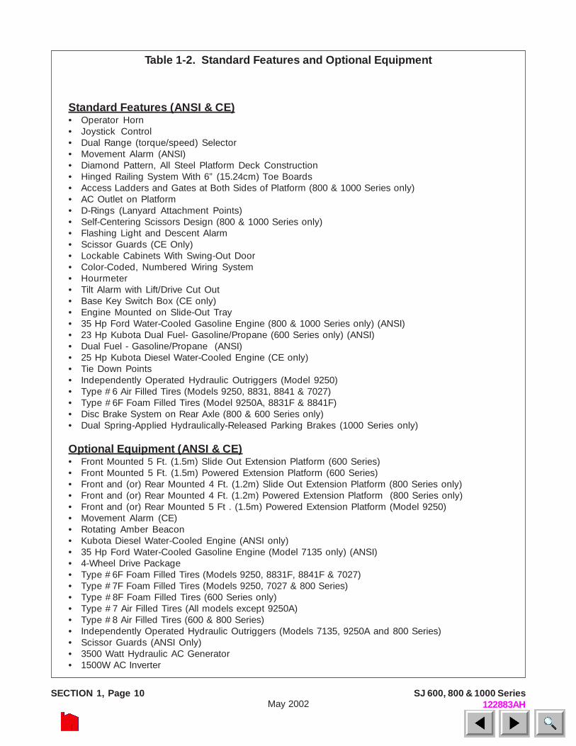
Standard Features (ANSI & CE)• Operator Horn• Joystick Control• Dual Range (torque/speed) Selector• Movement Alarm (ANSI)• Diamond Pattern, All Steel Platform Deck Construction• Hinged Railing System With 6” (15.24cm) Toe Boards• Access Ladders and Gates at Both Sides of Platform (800 & 1000 Series only)• AC Outlet on Platform• D-Rings (Lanyard Attachment Points)• Self-Centering Scissors Design (800 & 1000 Series only)• Flashing Light and Descent Alarm• Scissor Guards (CE Only)• Lockable Cabinets With Swing-Out Door• Color-Coded, Numbered Wiring System• Hourmeter• Tilt Alarm with Lift/Drive Cut Out• Base Key Switch Box (CE only)• Engine Mounted on Slide-Out Tray• 35 Hp Ford Water-Cooled Gasoline Engine (800 & 1000 Series only) (ANSI)• 23 Hp Kubota Dual Fuel- Gasoline/Propane (600 Series only) (ANSI)• Dual Fuel - Gasoline/Propane (ANSI)• 25 Hp Kubota Diesel Water-Cooled Engine (CE only)• Tie Down Points• Independently Operated Hydraulic Outriggers (Model 9250)• Type #6 Air Filled Tires (Models 9250, 8831, 8841 & 7027)• Type #6F Foam Filled Tires (Model 9250A, 8831F & 8841F)• Disc Brake System on Rear Axle (800 & 600 Series only)• Dual Spring-Applied Hydraulically-Released Parking Brakes (1000 Series only)
Optional Equipment (ANSI & CE)• Front Mounted 5 Ft. (1.5m) Slide Out Extension Platform (600 Series)• Front Mounted 5 Ft. (1.5m) Powered Extension Platform (600 Series)• Front and (or) Rear Mounted 4 Ft. (1.2m) Slide Out Extension Platform (800 Series only)• Front and (or) Rear Mounted 4 Ft. (1.2m) Powered Extension Platform (800 Series only)• Front and (or) Rear Mounted 5 Ft . (1.5m) Powered Extension Platform (Model 9250)• Movement Alarm (CE)• Rotating Amber Beacon• Kubota Diesel Water-Cooled Engine (ANSI only)• 35 Hp Ford Water-Cooled Gasoline Engine (Model 7135 only) (ANSI)• 4-Wheel Drive Package• Type #6F Foam Filled Tires (Models 9250, 8831F, 8841F & 7027)• Type #7F Foam Filled Tires (Models 9250, 7027 & 800 Series)• Type #8F Foam Filled Tires (600 Series only)• Type #7 Air Filled Tires (All models except 9250A)• Type #8 Air Filled Tires (600 & 800 Series)• Independently Operated Hydraulic Outriggers (Models 7135, 9250A and 800 Series)• Scissor Guards (ANSI Only)• 3500 Watt Hydraulic AC Generator• 1500W AC Inverter
Table 1-2. Standard Features and Optional Equipment
SECTION 1, Page 11SJ 600, 800 & 1000 Series122883AH May 2002
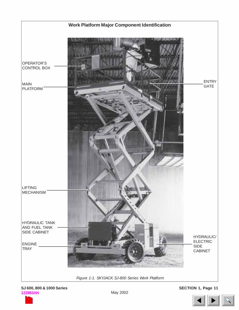
Figure 1-1. SKYJACK SJ-800 Series Work Platform
OPERATOR’SCONTROL BOX
ENTRYGATEMAIN
PLATFORM
LIFTINGMECHANISM
HYDRAULIC TANKAND FUEL TANKSIDE CABINET
ENGINETRAY
HYDRAULIC/ELECTRICSIDECABINET
Work Platform Major Component Identification

SECTION 2, Page 13SJ 600, 800 & 1000 Series122883AH May 2002
2
SECTION 2OPERATION
Operating Controls Identification
The following descriptions are for identification,explanation and locating purposes only. A qualifiedoperator MUST read and completely understandthese descriptions before operating this workplatform. Procedures for operating this work platformare detailed in the “OPERATING PROCEDURES”section. Both standard and optional controls areidentified in this section. Therefore, some controlsmay be included that are not furnished on your workplatform.
Base Controls
Electrical Panel
Figure 2-1. Electrical Panel
Electrical Panel - This control station is located in theHydraulic/Electric Side Cabinet. It contains thefollowing controls:
1. Up Push-Button Switch - This push-button switchwill raise the platform to desired height.
2. Down Push-Button Switch - This push-buttonswitch will lower the platform to desired height.
3. Hour meter - This gauge records engine runningtime.
4. 20 Amp Circuit Breaker Resets - In the event ofa power overload or positive circuit grounding, circuitbreaker will pop out.
Emergency Battery Disconnect Switch
Figure 2-2. Emergency Battery Disconnect Switch
1. Emergency Battery Disconnect Switch Locatedat the front of the Hydraulic/Electric Side Cabinet, thisswitch when in the “OFF” position, disconnects powerto all circuits. Switch MUST be in “ON” position tooperate any circuit.
2
1
4
3
1
SECTION 2, Page 14 SJ 600, 800 & 1000 Series122883AHMay 2002
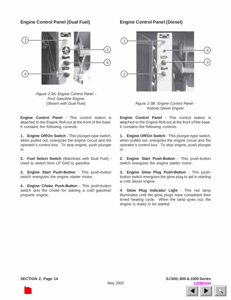
Engine Control Panel (Dual Fuel)
Figure 2-3A. Engine Control Panel -Ford Gasoline Engine
(Shown with Dual Fuel)
Engine Control Panel - This control station isattached to the Engine Roll-out at the front of the base.It contains the following controls:
1. Engine Off/On Switch - This plunger-type switch,when pulled out, energizes the engine circuit and theoperator’s control box. To stop engine, push plungerin.
2. Fuel Select Switch (Machines with Dual Fuel) -Used to switch from LP GAS to gasoline
3. Engine Start Push-Button - This push-buttonswitch energizes the engine starter motor.
4. Engine Choke Push-Button - This push-buttonswitch sets the choke for starting a cold gasoline/propane engine.
Engine Control Panel (Diesel)
Figure 2-3B. Engine Control Panel -Kubota Diesel Engine
Engine Control Panel - This control station isattached to the Engine Roll-out at the front of the base.It contains the following controls:
1. Engine Off/On Switch - This plunger-type switch,when pulled out, energizes the engine circuit and theoperator’s control box. To stop engine, push plungerin.
2. Engine Start Push-Button - This push-buttonswitch energizes the engine starter motor.
3. Engine Glow Plug Push-Button - This push-button switch energizes the glow plug to aid in startinga cold diesel engine.
4. Glow Plug Indicator Light - This red lampilluminates until the glow plugs have completed theirtimed heating cycle. When the lamp goes out, theengine is ready to be started.
2
1
4
3
2
1
4
3
SECTION 2, Page 15SJ 600, 800 & 1000 Series122883AH May 2002
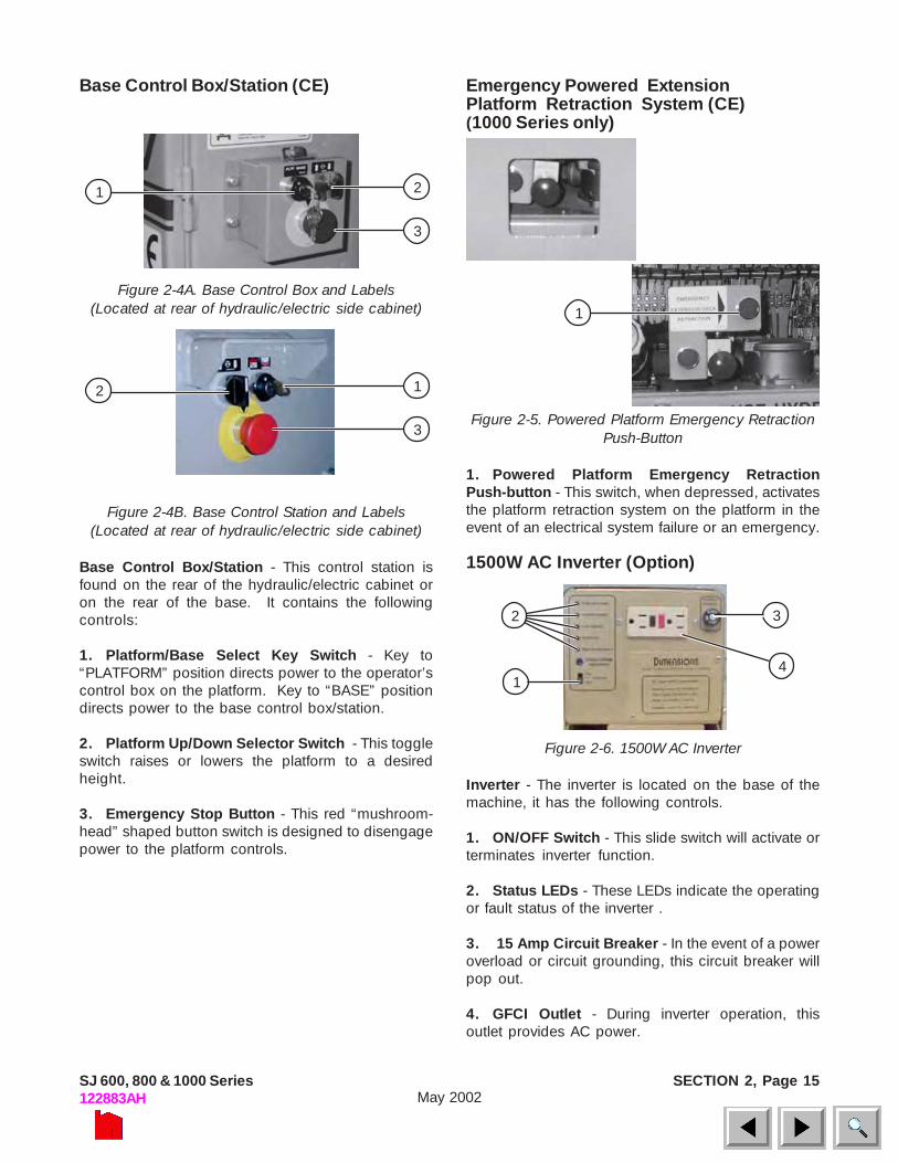
Base Control Box/Station (CE)
Figure 2-4A. Base Control Box and Labels(Located at rear of hydraulic/electric side cabinet)
Figure 2-4B. Base Control Station and Labels(Located at rear of hydraulic/electric side cabinet)
Base Control Box/Station - This control station isfound on the rear of the hydraulic/electric cabinet oron the rear of the base. It contains the followingcontrols:
1. Platform/Base Select Key Switch - Key to“PLATFORM” position directs power to the operator’scontrol box on the platform. Key to “BASE” positiondirects power to the base control box/station.
2. Platform Up/Down Selector Switch - This toggleswitch raises or lowers the platform to a desiredheight.
3. Emergency Stop Button - This red “mushroom-head” shaped button switch is designed to disengagepower to the platform controls.
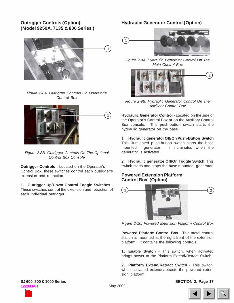
Emergency Powered ExtensionPlatform Retraction System (CE)(1000 Series only)
Figure 2-5. Powered Platform Emergency RetractionPush-Button
1. Powered Platform Emergency RetractionPush-button - This switch, when depressed, activatesthe platform retraction system on the platform in theevent of an electrical system failure or an emergency.
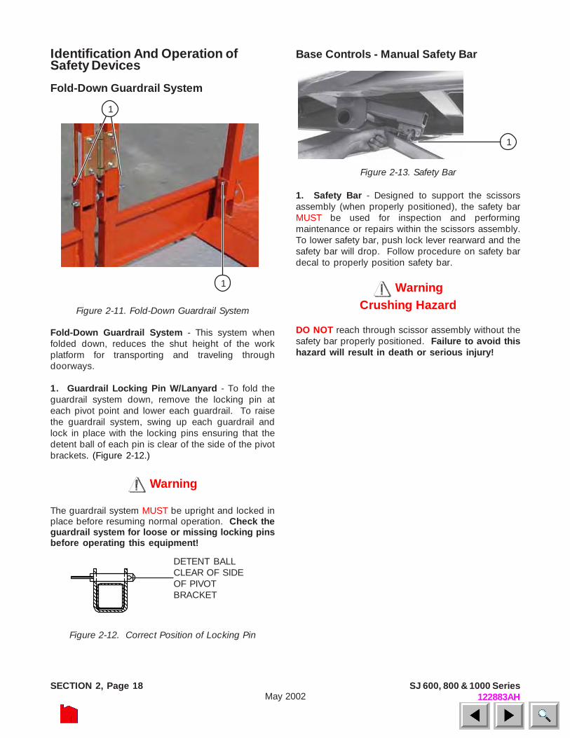
1500W AC Inverter (Option)
Figure 2-6. 1500W AC Inverter
Inverter - The inverter is located on the base of themachine, it has the following controls.
1. ON/OFF Switch - This slide switch will activate orterminates inverter function.
2. Status LEDs - These LEDs indicate the operatingor fault status of the inverter .
3. 15 Amp Circuit Breaker - In the event of a poweroverload or circuit grounding, this circuit breaker willpop out.
4. GFCI Outlet - During inverter operation, thisoutlet provides AC power.
21
3
1
2
14
3
12
3

SECTION 2, Page 16 SJ 600, 800 & 1000 Series122883AHMay 2002
5. Enable Push-Button - When depressed andheld, this push-button switch brings power to the liftor outrigger circuits.
6. Emergency Stop Button - When struck, this redpush-button switch disconnects power to the controlcircuit.
7. Off/Lift/Drive Select Key Switch - Key to “OFF”position disconnects power to the control box. Keyto “LIFT” position brings power to the Lift EnablePush-button. Key to “DRIVE” position brings powerto the Drive/Steer Controller.
8. Up/Down Selector Switch - This rotating selectorswitch raises or lowers the platform to the desiredheight.
9. Platform Power Indicator Light - Light will glowwhen key switch is in “LIFT” or “DRIVE” position.Light will not glow when key switch is in “OFF”position.
10. Low/High Throttle Select Switch - This rotaryswitch allows selection between high and low enginethrottle speeds.
11. Low/High Range Select Switch - This rotaryswitch selects “LOW” range (high torque) or “HIGH”range (high speed).
12. Drive/Steer Controller - A one-hand toggle typelever to control steer and three-speed drive motion. Itis a “deadman” control which returns to neutral whenreleased.
13.Drive Enable Switch - This momentary “Trigger”style switch energizes the drive/steer controller. Itmust be held depressed continuously while engagingeither the drive or steer functions.
Platform ControlsOperator’s Control Box
Figure 2-7. Operator’s Control Box
Operator’s Control Box - This metal control station ismounted at the right front of the platform. It containsthe following controls:
1. Torque Toggle Switch - This toggle switch, whenin the “ ” position, cuts out High Range and 3rdspeed to provide maximum torque when climbinggrades and in rough terrain. When in the “ ”position, all three speeds are available.
2. Operator Horn Push-Button - Located on theside of the Operator’s Control Box, this push-buttonswitch, when depressed, sounds an automotive-typehorn.
3. Engine Choke Push-Button (Dual fuel engines) -Located on the side of the control box, this push-button sets choke for starting a cold gasoline engine.
Glow Plug Push-Button (Diesel Engines) -Located on the side of the control box, this push-button powers the glow plug for starting cold dieselengines.
4. Engine Start Push-Button - Located on the sideof the control box, this push-button energizes theengine starter motor.
12
11
10
9
8
76
5
2
1
4
3
13
SECTION 2, Page 17SJ 600, 800 & 1000 Series122883AH May 2002
Outrigger Controls (Option)(Model 9250A, 7135 & 800 Series )
Figure 2-8A. Outrigger Controls On Operator’sControl Box
Figure 2-8B. Outrigger Controls On The OptionalControl Box Console
Outrigger Controls - Located on the Operator’sControl Box, these switches control each outrigger’sextension and retraction
1. Outrigger Up/Down Control Toggle Switches -These switches control the extension and retraction ofeach individual outrigger
1
1 2
Hydraulic Generator Control (Option)
Figure 2-9A. Hydraulic Generator Control On TheMain Control Box
Figure 2-9B. Hydraulic Generator Control On TheAuxiliary Control Box
Hydraulic Generator Control - Located on the side ofthe Operator’s Control Box or on the Auxiliary ControlBox console. This push-button switch starts thehydraulic generator on the base.
1. Hydraulic generator Off/On Push-Button SwitchThis illuminated push-button switch starts the basemounted generator. It illuminates when thegenerator is activated.
2. Hydraulic generator Off/On Toggle Switch Thisswitch starts and stops the base mounted generator.
Powered Extension PlatformControl Box (Option)
Figure 2-10. Powered Extension Platform Control Box
Powered Platform Control Box - This metal controlstation is mounted at the right front of the extensionplatform. It contains the following controls:
1. Enable Switch - This switch, when activatedbrings power to the Platform Extend/Retract Switch.
2. Platform Extend/Retract Switch - This switch,when activated extends/retracts the powered exten-sion platform.
1
1
2
SECTION 2, Page 18 SJ 600, 800 & 1000 Series122883AHMay 2002
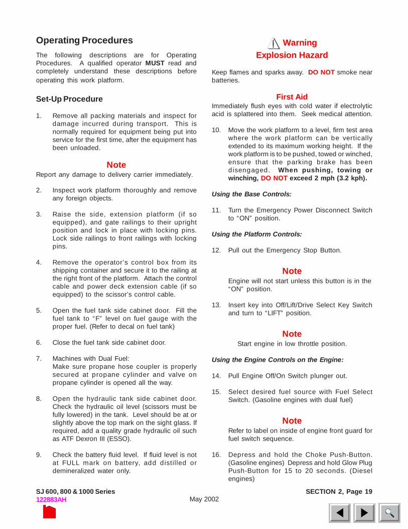
Identification And Operation ofSafety Devices
Fold-Down Guardrail System
Figure 2-11. Fold-Down Guardrail System
Fold-Down Guardrail System - This system whenfolded down, reduces the shut height of the workplatform for transporting and traveling throughdoorways.
1. Guardrail Locking Pin W/Lanyard - To fold theguardrail system down, remove the locking pin ateach pivot point and lower each guardrail. To raisethe guardrail system, swing up each guardrail andlock in place with the locking pins ensuring that thedetent ball of each pin is clear of the side of the pivotbrackets. (Figure 2-12.)
Warning
The guardrail system MUST be upright and locked inplace before resuming normal operation. Check theguardrail system for loose or missing locking pinsbefore operating this equipment!
Figure 2-12. Correct Position of Locking Pin
Base Controls - Manual Safety Bar
Figure 2-13. Safety Bar
1. Safety Bar - Designed to support the scissorsassembly (when properly positioned), the safety barMUST be used for inspection and performingmaintenance or repairs within the scissors assembly.To lower safety bar, push lock lever rearward and thesafety bar will drop. Follow procedure on safety bardecal to properly position safety bar.
WarningCrushing Hazard
DO NOT reach through scissor assembly without thesafety bar properly positioned. Failure to avoid thishazard will result in death or serious injury!
DETENT BALLCLEAR OF SIDEOF PIVOTBRACKET
1
1
1
SECTION 2, Page 19SJ 600, 800 & 1000 Series122883AH May 2002
Operating ProceduresThe following descriptions are for OperatingProcedures. A qualified operator MUST read andcompletely understand these descriptions beforeoperating this work platform.
Set-Up Procedure
1. Remove all packing materials and inspect fordamage incurred during transport. This isnormally required for equipment being put intoservice for the first time, after the equipment hasbeen unloaded.
NoteReport any damage to delivery carrier immediately.
2. Inspect work platform thoroughly and removeany foreign objects.
3. Raise the side, extension platform (if soequipped), and gate railings to their uprightposition and lock in place with locking pins.Lock side railings to front railings with lockingpins.
4. Remove the operator’s control box from itsshipping container and secure it to the railing atthe right front of the platform. Attach the controlcable and power deck extension cable (if soequipped) to the scissor’s control cable.
5. Open the fuel tank side cabinet door. Fill thefuel tank to “F” level on fuel gauge with theproper fuel. (Refer to decal on fuel tank)
6. Close the fuel tank side cabinet door.
7. Machines with Dual Fuel:Make sure propane hose coupler is properlysecured at propane cylinder and valve onpropane cylinder is opened all the way.
8. Open the hydraulic tank side cabinet door.Check the hydraulic oil level (scissors must befully lowered) in the tank. Level should be at orslightly above the top mark on the sight glass. Ifrequired, add a quality grade hydraulic oil suchas ATF Dexron III (ESSO).
9. Check the battery fluid level. If fluid level is notat FULL mark on battery, add distilled ordemineralized water only.
WarningExplosion Hazard
Keep flames and sparks away. DO NOT smoke nearbatteries.
First AidImmediately flush eyes with cold water if electrolyticacid is splattered into them. Seek medical attention.
10. Move the work platform to a level, firm test areawhere the work platform can be verticallyextended to its maximum working height. If thework platform is to be pushed, towed or winched,ensure that the parking brake has beendisengaged. When pushing, towing orwinching, DO NOT exceed 2 mph (3.2 kph).
Using the Base Controls:
11. Turn the Emergency Power Disconnect Switchto “ON” position.
Using the Platform Controls:
12. Pull out the Emergency Stop Button.
NoteEngine will not start unless this button is in the“ON” position.
13. Insert key into Off/Lift/Drive Select Key Switchand turn to “LIFT” position.
NoteStart engine in low throttle position.
Using the Engine Controls on the Engine:
14. Pull Engine Off/On Switch plunger out.
15. Select desired fuel source with Fuel SelectSwitch. (Gasoline engines with dual fuel)
NoteRefer to label on inside of engine front guard forfuel switch sequence.
16. Depress and hold the Choke Push-Button.(Gasoline engines) Depress and hold Glow PlugPush-Button for 15 to 20 seconds. (Dieselengines)

SECTION 2, Page 20 SJ 600, 800 & 1000 Series122883AHMay 2002
17. Depress and hold the Engine Start Push-Buttonuntil the engine starts, then release. DO NOTover crank the starter. Release the Engine ChokePush-button.
Using the Base Controls:
18. Raise the platform with the “Up” Selector Switchon the Base Control Box until the open heightbetween scissors center pins is approximately21" (53.34cm) for 800 & 1000 Series and 18”(45.72cm) for 600 Series.
19. Unlatch and carefully swing down the safety bar.Follow procedure on safety bar decal to properlyposition safety bar.
Warning
Crushing HazardDO NOT reach through scissor assembly without thesafety bar properly positioned. Failure to avoid thishazard will result in death or serious injury!
20. Slowly lower the platform with “Down” SelectorSwitch on the Base Control Box until the scissorsassembly is firmly resting on the safety bar.
21. Inspect all hoses, fittings, wires, valves, etc. forleaks, loose or missing parts, hidden damage,and foreign material.
22. Raise the platform with the Up Switch until theopen height between scissors center pins isapproximately 21" (53.34cm) for 800 & 1000Series and 18” (45.72cm) for 600 Series.
23. Carefully swing up safety bar and lock inposition.
24. Again, raise the platform with the Up Switch untilthe platform has reached maximum workingheight.
NoteRefer to Table 1-1. Specifications and Features forproper lift and lowering times.
25. Use the Down Switch to lower the platform toit’s fully lowered position.
26. Your SKYJACK Model is now ready for use byan authorized, qualified operator who has readand completely understands ALL of Section 2,OPERATION in this manual.
Operating ProceduresPrestart Checks
1. Carefully read and completely understand ALLof Section 2, OPERATION in this manual andALL warnings and instruction decals on the workplatform.
2. Check for any obstacles around the workplatform and in the path of travel such as holes,drop offs, debris, ditches and soft fill.
3. Check overhead clearances.
4. Make sure all guardrails are in place and lockedin position.
OPERATOR’S CHECKLISTINSPECT AND/OR TEST THE FOLLOWING DAILY
OR AT BEGINNING OF EACH SHIFT
1. OPERATING AND EMERGENCY CONTROLS.2. SAFETY DEVICES AND LIMIT SWITCHES.3. PERSONAL PROTECTIVE DEVICES.4. TIRES AND WHEELS.5. OUTRIGGERS (IF EQUIPPED) AND OTHER STRUCTURES.6. AIR, HYDRAULIC AND FUEL SYSTEM(S) FOR LEAKS.7. LOOSE OR MISSING PARTS.8. CABLES AND WIRING HARNESSES.9. PLACARDS, WARNINGS, CONTROL MARKINGS AND
OPERATING MANUALS.10. GUARDRAIL SYSTEM, INCLUDING LOCKING PINS.11. ENGINE OIL LEVEL (IF SO EQUIPPED).12. BATTERY FLUID LEVEL.13. HYDRAULIC RESERVOIR LEVEL.14. COOLANT LEVEL (IF SO EQUIPPED).15. PARKING BRAKE (CHECK OPERATION).
WarningDO NOT OPERATE THIS EQUIPMENTWITHOUT PROPER AUTHORIZATION ANDTRAINING. DEATH OR SERIOUS INJURYCOULD RESULT FROM IMPROPER USEOF THIS EQUIPMENT!

SECTION 2, Page 21SJ 600, 800 & 1000 Series122883AH May 2002
Operator Qualifications
Only trained and authorized persons should use thiswork platform. Safe use of this work platform requiresthe operator to understand the limitations andwarnings, operating procedures and operator’sresponsibility for maintenance. Accordingly, theoperator MUST understand and be familiar with thisoperating manual, its warnings and instructions andALL warnings and instructions on the work platform.The operator also MUST be familiar with employer’swork rules, related government regulations and beable to demonstrate his/her ability to understand andoperate THIS make and model work platform in thepresence of a qualified person.
Start and Operation
Using the Base Controls:
1. Turn Emergency Power Disconnect Switch to“ON” position. CE units - make sure base controlemergency stop button is in the “ON” position.
Using the Engine Controls on the Engine:
2. Pull Engine Off/On Switch plunger out.
3. Select desired fuel source with Fuel SelectSwitch. (Gasoline engines with Dual Fuel)
NoteRefer to label on inside of engine front guard for fuelswitch sequence.
4. Use the ladder of the work platform to accessthe work platform deck. Close and latch the gate.
Using the Platform Controls:
WarningTO PROTECT AGAINST UNINTENDEDMOVEMENT OF THE WORK PLATFORM, PUSHIN THE EMERGENCY STOP BUTTON AFTER YOUHAVE ARRIVED AT YOUR DESIRED LOCATIONOR ELEVATION.
5. Pull out the Emergency Stop Button.
6. Insert key into the Off/Lift/Drive Select Key Switch,then select “LIFT” or “DRIVE”. Select “LOW”position with HI/LOW Throttle Select Switch.
7. If the engine is cold, depress and hold the EngineChoke Push-button (Gasoline engines) ordepress and hold the Glow Plug Push-buttonfor 15 to 20 seconds) (Diesel engines) andrelease.
8. Depress and hold the Engine Start Push-Buttonuntil engine starts, then release. DO NOT overcrank the starter.
9. Select “HIGH” position with the Low/High ThrottleSelect Switch.
10. To Raise the Platform: Ensure the emergencystop button is pulled out. Select “LIFT” positionwith Off/Lift/Drive Select Key Switch. Depressand hold the Enable Push-button, then select“ ” (up) position with Up/Down Selector Switch.Release switch to stop.
11. To Lower the Platform: Ensure the emergencystop button is pulled out. Select “LIFT” positionwith Off/Lift/Drive Select Key Switch. Depressand hold the Enable Push-button, then select“ ” (down) position with Up/Down SelectorSwitch. Release switch to stop. A warning alarmwill sound while lowering.
12. If High Torque is Desired: Select “LOW” positionwith the Low/High Range Select Switch. Select“LOW” range when climbing grades, travelingin rough terrain and when loading or unloadingthe work platform.If High Speed is Desired: Select “HIGH”position with the Low/High Range Select Switch.Select “HIGH” range when traveling on a hardlevel surface with the platform fully lowered.
13. To Drive Forward or in Reverse:1- Ensure the emergency stop button is pulled
out. Select “DRIVE” position with the Lift/Off/Drive Key Switch.
2- Activate and hold the Drive Enable triggerswitch (by squeezing it towards the joystick).
3- Push or pull the controller handle forward orbackward to the desired speed and directionof platform travel.
4- Return the joystick to the neutral centerposition to stop. Release the Enable triggerswitch.

SECTION 2, Page 22 SJ 600, 800 & 1000 Series122883AHMay 2002
Shutdown Procedure
1. Completely lower the platform.
2. Turn key to “OFF” position and remove key fromOff/Lift/Drive Select Key Switch in control box.
3. Push Emergency Stop Button(s) in.
4. Turn Emergency Power Disconnect Switch to“OFF” position. CE units - remove key thenpush in Emergency Stop Button on the basecontrol box.
14. To Steer: Select “DRIVE” position with Off/Lift/Drive Select Key Switch. Activate and hold theDrive Enable trigger switch (by squeezing ittowards the joystick), then press the rockerswitch on top of the Drive/Steer Controller handlein the direction you wish to steer.
15. To Climb a Grade: Select “ ” position with
the Torque Toggle Switch.
WarningMACHINE MUST BE IN FULLY RETRACTEDPOSITION
16. To extend/retract a manual extension platform:To extend the platform remove the retaininglocking pins and push/pull the extension platformusing the push bar until the desired extension isreached. Reinsert the locking pins to preventaccidental movement of the extension deckduring travel or transport.
17. To extend/retract a hydraulic poweredextension platform: To extend the platform,turn key to “LIFT” position with Off/Lift/DriveSelect Key Switch, activate the Enable Switch,then push the extension/retraction toggle switchto the “ ” position until desired extension isreached. Release switch to stop. To retract theplatform, turn key to “LIFT” position with Off/Lift/Drive Select Key Switch, activate the EnableSwitch, then push the extension/retraction toggleswitch to the “ ” (retract) position until desiredretraction is reached. Release switch to stop.
18. To switch from LP GAS to gasoline: Move fuelselector switch on engine control panel to the“GASOLINE” position. To shut off fuel, moveswitch to “OFF” position.To switch from gasoline to LP GAS: With theengine running, move switch to “OFF” positionand let engine run until gasoline is exhaustedfrom carburetor. When engine stops, moveswitch to “LP GAS” position and restart engine.Make sure LP GAS valve is ON when switchingfrom gasoline to LP GAS and valve is OFF whenswitching from LP GAS to gasoline.
SECTION 2, Page 23SJ 600, 800 & 1000 Series122883AH May 2002
Emergency Lowering System(1000 Series only)
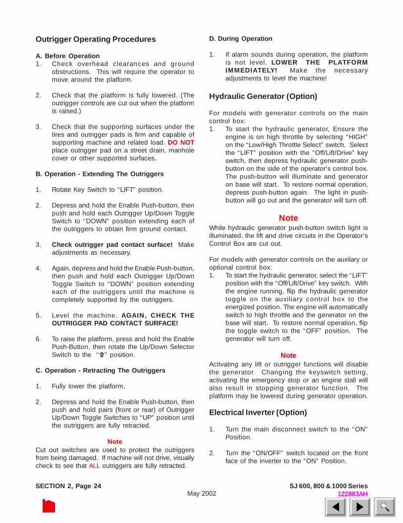
Figure 2-15. Emergency Lowering System
Emergency Lowering System - Located on thehydraulic tank and accessed through a hole in thehydraulic/electric cabinet door, this system allowsplatform lowering in the event of an emergency or anelectrical system failure. An auxiliary battery providespower for the push-button switch to activate alowering valve on the base of each lift cylinder.
Emergency Lowering Push-Button Switch (1) andEmergency Lowering Valve (2) - To lower theplatform, depress and hold this red push-buttonswitch, then pull the valve plunger out. The platformwill gradually lower. Release the valve plunger to stop.
Emergency Lowering System(600 & 800 Series)
Figure 2-14. Emergency Lowering System
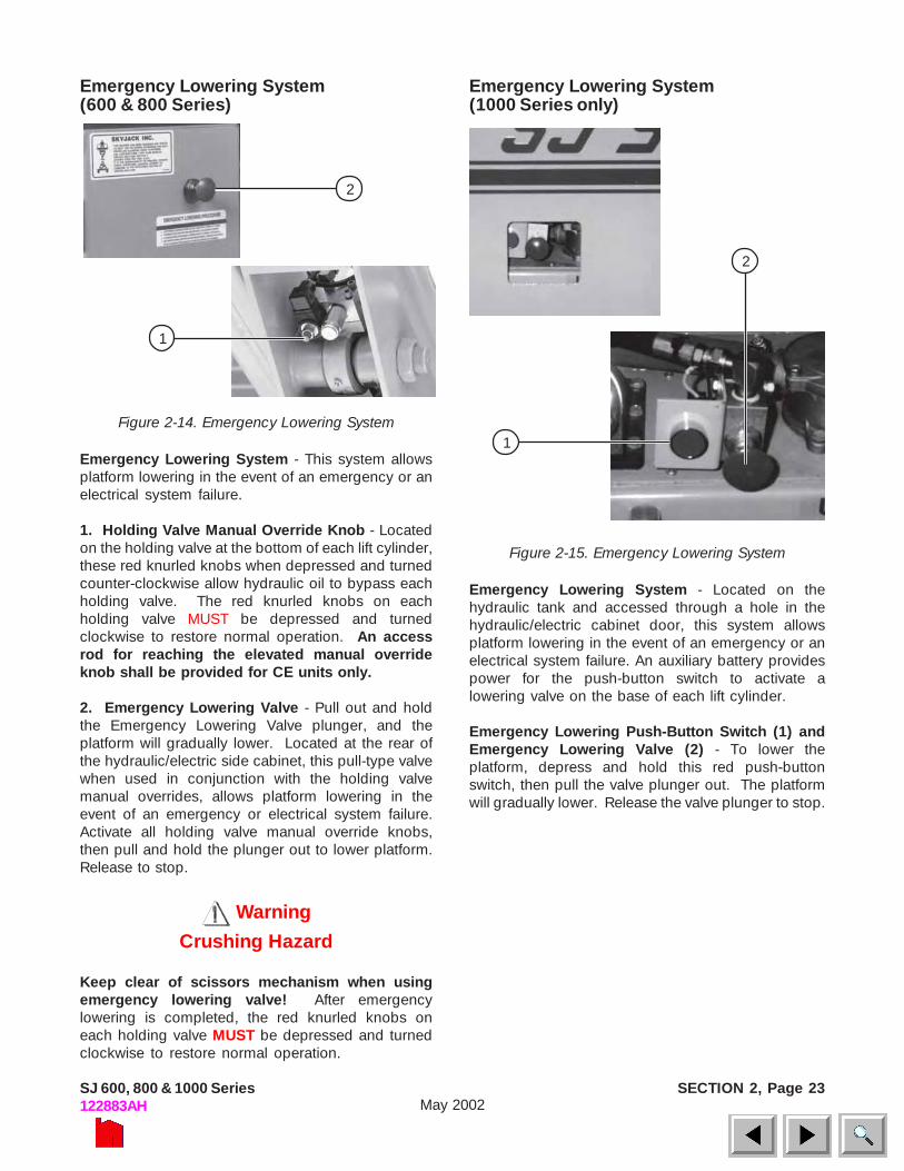
Emergency Lowering System - This system allowsplatform lowering in the event of an emergency or anelectrical system failure.
1. Holding Valve Manual Override Knob - Locatedon the holding valve at the bottom of each lift cylinder,these red knurled knobs when depressed and turnedcounter-clockwise allow hydraulic oil to bypass eachholding valve. The red knurled knobs on eachholding valve MUST be depressed and turnedclockwise to restore normal operation. An accessrod for reaching the elevated manual overrideknob shall be provided for CE units only.
2. Emergency Lowering Valve - Pull out and holdthe Emergency Lowering Valve plunger, and theplatform will gradually lower. Located at the rear ofthe hydraulic/electric side cabinet, this pull-type valvewhen used in conjunction with the holding valvemanual overrides, allows platform lowering in theevent of an emergency or electrical system failure.Activate all holding valve manual override knobs,then pull and hold the plunger out to lower platform.Release to stop.
Warning
Crushing Hazard
Keep clear of scissors mechanism when usingemergency lowering valve! After emergencylowering is completed, the red knurled knobs oneach holding valve MUST be depressed and turnedclockwise to restore normal operation.
2
1
2
1
SECTION 2, Page 24 SJ 600, 800 & 1000 Series122883AHMay 2002
Outrigger Operating Procedures
A. Before Operation1. Check overhead clearances and ground
obstructions. This will require the operator tomove around the platform.
2. Check that the platform is fully lowered. (Theoutrigger controls are cut out when the platformis raised.)
3. Check that the supporting surfaces under thetires and outrigger pads is firm and capable ofsupporting machine and related load. DO NOTplace outrigger pad on a street drain, manholecover or other supported surfaces.
B. Operation - Extending The Outriggers
1. Rotate Key Switch to “LIFT” position.
2. Depress and hold the Enable Push-button, thenpush and hold each Outrigger Up/Down ToggleSwitch to “DOWN” position extending each ofthe outriggers to obtain firm ground contact.
3. Check outrigger pad contact surface! Makeadjustments as necessary.
4. Again, depress and hold the Enable Push-button,then push and hold each Outrigger Up/DownToggle Switch to “DOWN” position extendingeach of the outriggers until the machine iscompletely supported by the outriggers.
5. Level the machine. AGAIN, CHECK THEOUTRIGGER PAD CONTACT SURFACE!
6. To raise the platform, press and hold the EnablePush-Button, then rotate the Up/Down SelectorSwitch to the “ ” position.
C. Operation - Retracting The Outriggers
1. Fully lower the platform.
2. Depress and hold the Enable Push-button, thenpush and hold pairs (front or rear) of OutriggerUp/Down Toggle Switches to “UP” position untilthe outriggers are fully retracted.
NoteCut out switches are used to protect the outriggersfrom being damaged. If machine will not drive, visuallycheck to see that ALL outriggers are fully retracted.
D. During Operation
1. If alarm sounds during operation, the platformis not level. LOWER THE PLATFORMIMMEDIATELY! Make the necessaryadjustments to level the machine!
Hydraulic Generator (Option)
For models with generator controls on the maincontrol box:1. To start the hydraulic generator, Ensure the
engine is on high throttle by selecting “HIGH”on the “Low/High Throttle Select” switch. Selectthe “LIFT” position with the “Off/Lift/Drive” keyswitch, then depress hydraulic generator push-button on the side of the operator’s control box.The push-button will illuminate and generatoron base will start. To restore normal operation,depress push-button again. The light in push-button will go out and the generator will turn off.
NoteWhile hydraulic generator push-button switch light isilluminated, the lift and drive circuits in the Operator’sControl Box are cut out.
For models with generator controls on the auxilary oroptional control box:1. To start the hydraulic generator, select the “LIFT”
position with the “Off/Lift/Drive” key switch. Withthe engine running, flip the hydraulic generatortoggle on the auxiliary control box to theenergized position. The engine will automaticallyswitch to high throttle and the generator on thebase will start. To restore normal operation, flipthe toggle switch to the “OFF” position. Thegenerator will turn off.
NoteActivating any lift or outrigger functions will disablethe generator. Changing the keyswitch setting,activating the emergency stop or an engine stall willalso result in stopping generator function. Theplatform may be lowered during generator operation.
Electrical Inverter (Option)
1. Turn the main disconnect switch to the “ON”Position.
2. Turn the “ON/OFF” switch located on the frontface of the inverter to the “ON” Position.

SECTION 2, Page 25SJ 600, 800 & 1000 Series122883AH May 2002
3. Start the machine and turn the throttle switch tothe high idle setting.
4. Inverter activation is indicated by a glowing greenLED on the front face of the inverter.
5. To turn off the inverter, shut down the platformengine and/or slide the “ON/OFF” switch on theinverter to the “OFF” position.
NoteThe inverter will only supply power to the platformwhen the engine is running and the throttle switch isset to the HIGH idle position. Deselecting the high idlethrottle setting or stopping the engine will turn theinverter off.
Winching and Towing Procedures(600 & 800 Series)
WarningWhen Towing, DO NOT drive onto a downward slopeor brake the towing vehicle rapidly.
Preparation for Winching Or Towing
Parking Brake System
Figure 2-16. Disc Parking Brake
1 - 3. Parking Brake Disc -This device disengagesthe brake disc(1) when driving forward or in reverse.A hydraulic brake cylinder(2), linked to a disccaliper(3), engages and disengages a brake disc onthe rear axle drive shaft yoke. The brake MUST bemanually disengaged for pushing, towing orwinching. DO NOT push or tow the work platformonto a downward slope or pull the platform downan incline towards the winch. The special procedurefor manually disengaging the parking brake is asfollows:
WarningDO NOT manually disengage the parking brakes ifthe work platform is on a slope.
Figure 2-17. Parking Brake Release Hand Pump andBrake Valve Plunger
4 - 5. Parking Brake Release Hand Pump(4) andBrake Valve Plunger(5) - Located on the brakemanifold in the hydraulic electric side cabinet, thishand operated pump MUST be used when pushing,towing or winching the work platform. To release theparking brake:
1. Make sure that the work platform is on levelground. Chock or block the wheels to keepwork platform from rolling.
2. Turn Emergency Power Disconnect Switch to“OFF” position.
3. Depress the black plunger on the Brake Valveuntil the plunger stays in.
4. Grasp the red hand pump plunger and rapidlydepress 60 to 80 times until firm resistance isfelt. The brake is now released.
5. Remove the wheel chocks or blocks, then push,tow or winch the work platform to the desiredlocation. When pushing, towing or winching,DO NOT exceed 2 mph (3.2 km/h). DO NOTpush or tow the platform onto a downwardslope or pull the platform down an inclinetowards the winch.
6. Position machine on a firm and level surface.Chock or block the wheels to prevent the platformfrom rolling or re-engage the parking brake bymomentarily activating the drive function.
NoteThe parking brake will reset automatically when thework platform is put back into service.
2
1
3
54
SECTION 2, Page 26 SJ 600, 800 & 1000 Series122883AHMay 2002
Winching And Towing Procedures(1000 Series only)
Warning
When Towing, DO NOT drive onto a downward slopeor brake the towing vehicle rapidly.
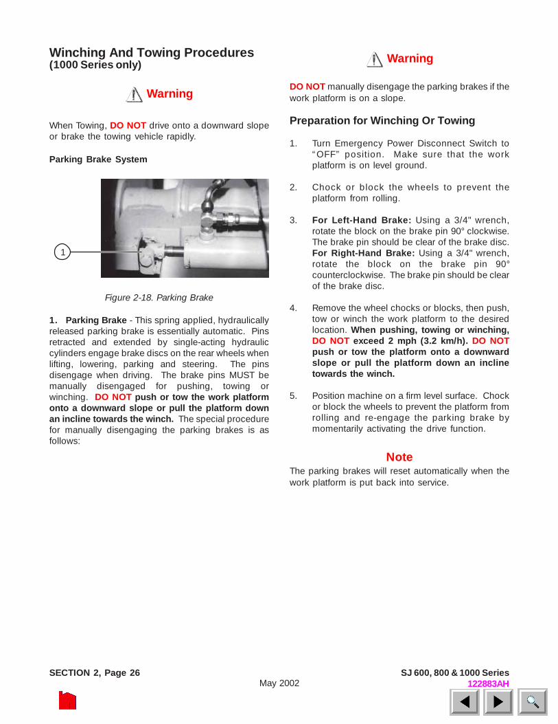
Parking Brake System
Figure 2-18. Parking Brake
1. Parking Brake - This spring applied, hydraulicallyreleased parking brake is essentially automatic. Pinsretracted and extended by single-acting hydrauliccylinders engage brake discs on the rear wheels whenlifting, lowering, parking and steering. The pinsdisengage when driving. The brake pins MUST bemanually disengaged for pushing, towing orwinching. DO NOT push or tow the work platformonto a downward slope or pull the platform downan incline towards the winch. The special procedurefor manually disengaging the parking brakes is asfollows:
Warning
DO NOT manually disengage the parking brakes if thework platform is on a slope.
Preparation for Winching Or Towing
1. Turn Emergency Power Disconnect Switch to“OFF” position. Make sure that the workplatform is on level ground.
2. Chock or block the wheels to prevent theplatform from rolling.
3. For Left-Hand Brake: Using a 3/4" wrench,rotate the block on the brake pin 90° clockwise.The brake pin should be clear of the brake disc.For Right-Hand Brake: Using a 3/4" wrench,rotate the block on the brake pin 90°counterclockwise. The brake pin should be clearof the brake disc.
4. Remove the wheel chocks or blocks, then push,tow or winch the work platform to the desiredlocation. When pushing, towing or winching,DO NOT exceed 2 mph (3.2 km/h). DO NOTpush or tow the platform onto a downwardslope or pull the platform down an inclinetowards the winch.
5. Position machine on a firm level surface. Chockor block the wheels to prevent the platform fromrolling and re-engage the parking brake bymomentarily activating the drive function.
NoteThe parking brakes will reset automatically when thework platform is put back into service.
1

SECTION 2, Page 27SJ 600, 800 & 1000 Series122883AH May 2002
Table 2-1. Owner’s Annual Inspection Record
MODEL NUMBER________________________________ SERIAL NUMBER________________________
RECORDING DATE
RECORDING YEAR #
1 2 3 4 5 6 7 8
OWNER’S NAME
INSPECTED BY

SECTION 2, Page 28 SJ 600, 800 & 1000 Series122883AHMay 2002
WARNING
Air pressure can affect stability. Temperature changes can affect air pressure. It is important to visually inspect all tires for proper tire inflation prior to use. Tires should be checked in the operating conditions
experienced by end user on a daily basis. Tire inflation pressures must be checked weekly with a calibrated gauge. If the measured pressure is less than the specification, re-inflate to the pressure specified. Tires
shall also not be subject to over-inflation above the recommended specification and tolerance range.
Tire Fill Specification Usage†
Pressure Psi (kPa)
600 Series
800 Series
1000 Series
Size Fill Type Ply Rating
Factory Listed
Sidewall Maximum 70
27
7027
F
71X
X
71XX
F
8831
8831
F
8841
8841
F
9250
9250
F
9250
A
#6 30-10-16.5 NHS 8 50*
(344.7)* 65
(448.2) S S S S
#6 32.3-10-16.5 OTR HD Stabilizer 10
70* (482.6)*
75 (517.1) S
#6 30-10-16.5 OTR Outrigger
10 75* (517.1)*
75 (517.1)
S
#7 31-15.5-15 NHS
Air
8 45*
(310.3)* Not
Available O O O O O
#6F 30-10-16.5 NHS 8 ** S S†† S S S S
#7F 31-15.5-15 NHS
Solid Urethane
8 ** O O O O O
* Factory preset @ 20°C, Check pressures regularly as tires can lose pressure over time and over different ambient temperatures even under normal conditions.
** Urethane used for filling #6F and #7F tires MUST be 55 durometer. † Usage: (S)tandard Or (O)ptional †† #6 foam tire is 30-10-16.5 OTR Outrigger Standard tires on early 7127 models only.
Rim Backspace Diagram
Backspace inches(mm) Rim Size 7027
7127 (Earlier models)
7127 (Later
models) 7135 8831 8841 9250 9250A
#6 & #6F 4-3/4” (121)
4-3/4” (121)
3-3/4” (95)
3-3/4” (95)
4-3/4” (121)
4-3/4” (121)
3-3/4” (95)
3-3/4” (95)
#7 & #7F All models are 5-5/16” (135)
Table 2-2. Tire Specifications
SECTION 2, Page 29SJ 600, 800 & 1000 Series122883AH May 2002
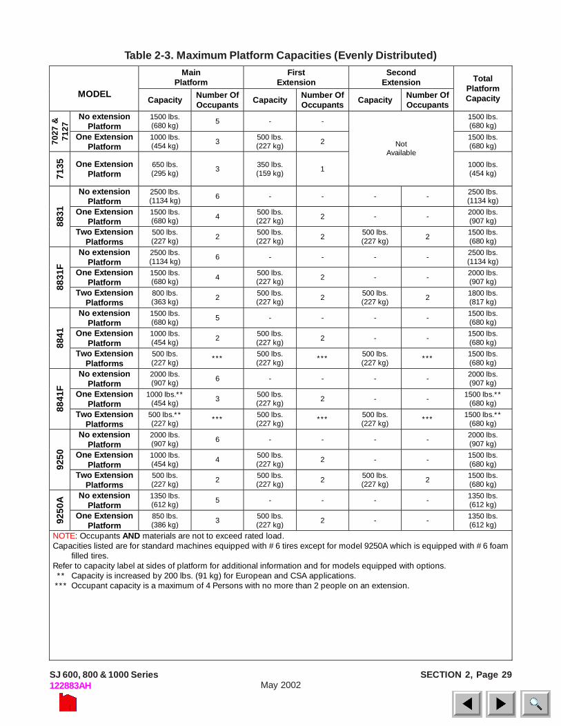
Table 2-3. Maximum Platform Capacities (Evenly Distributed)Main
Platform First
Extension Second
Extension MODEL
Capacity Number Of Occupants Capacity Number Of
Occupants Capacity Number Of Occupants
Total Platform Capacity
No extension Platform
1500 lbs. (680 kg) 5 - - 1500 lbs.
(680 kg)
7027
&
7127
One Extension Platform
1000 lbs. (454 kg) 3 500 lbs.
(227 kg) 2 1500 lbs. (680 kg)
7135
One Extension Platform
650 lbs. (295 kg) 3 350 lbs.
(159 kg) 1
Not
Available 1000 lbs.
(454 kg)
No extension Platform
2500 lbs. (1134 kg) 6 - - - - 2500 lbs.
(1134 kg)
One Extension Platform
1500 lbs. (680 kg) 4 500 lbs.
(227 kg) 2 - - 2000 lbs. (907 kg) 88
31
Two Extension Platforms
500 lbs. (227 kg) 2
500 lbs. (227 kg) 2
500 lbs. (227 kg) 2
1500 lbs. (680 kg)
No extension Platform
2500 lbs. (1134 kg)
6 - - - - 2500 lbs. (1134 kg)
One Extension Platform
1500 lbs. (680 kg) 4 500 lbs.
(227 kg) 2 - - 2000 lbs. (907 kg)
8831
F
Two Extension Platforms
800 lbs. (363 kg) 2 500 lbs.
(227 kg) 2 500 lbs. (227 kg) 2 1800 lbs.
(817 kg)
No extension Platform
1500 lbs. (680 kg) 5 - - - - 1500 lbs.
(680 kg)
One Extension Platform
1000 lbs. (454 kg) 2
500 lbs. (227 kg) 2 - -
1500 lbs. (680 kg) 88
41
Two Extension Platforms
500 lbs. (227 kg)
*** 500 lbs. (227 kg)
*** 500 lbs. (227 kg)
*** 1500 lbs. (680 kg)
No extension Platform
2000 lbs. (907 kg) 6 - - - - 2000 lbs.
(907 kg)
One Extension Platform
1000 lbs.** (454 kg) 3 500 lbs.
(227 kg) 2 - - 1500 lbs.** (680 kg)
8841
F
Two Extension Platforms
500 lbs.** (227 kg) *** 500 lbs.
(227 kg) *** 500 lbs. (227 kg) *** 1500 lbs.**
(680 kg)
No extension Platform
2000 lbs. (907 kg) 6 - - - -
2000 lbs. (907 kg)
One Extension Platform
1000 lbs. (454 kg)
4 500 lbs. (227 kg)
2 - - 1500 lbs. (680 kg) 92
50
Two Extension Platforms
500 lbs. (227 kg) 2 500 lbs.
(227 kg) 2 500 lbs. (227 kg) 2 1500 lbs.
(680 kg)
No extension Platform
1350 lbs. (612 kg) 5 - - - - 1350 lbs.
(612 kg)
9250
A
One Extension Platform
850 lbs. (386 kg) 3 500 lbs.
(227 kg) 2 - - 1350 lbs. (612 kg)
NOTE: Occupants AND materials are not to exceed rated load. Capacities listed are for standard machines equipped with #6 tires except for model 9250A which is equipped with #6 foam
filled tires. Refer to capacity label at sides of platform for additional information and for models equipped with options. ** Capacity is increased by 200 lbs. (91 kg) for European and CSA applications. *** Occupant capacity is a maximum of 4 Persons with no more than 2 people on an extension.

SECTION 2, Page 30 SJ 600, 800 & 1000 Series122883AHMay 2002
Table 2-4. Maintenance And Inspection Schedule Daily Weekly Monthly 3 Months 6 Months 12 Months* Engine Fuel leaks A A Engine oils H & I H & I Engine RPM G G Fuel filter F F Belts/Hoses A & C A & C Muffler B, C & J B, C & J Air cleaner A I A & I Fuel tank cap B & C B & C Coolant level A & L A & L Mechanical Structural damage/welds A A Locking Pins/Retainers A & B C A, B & C Parking brake B B Tires/wheels & fasteners A, B, C & R O & S A, B, C & O Guides/ rollers & slider pads A, B & N A, B & N Railings/Entry chains/gates A, B & C A, B & C Bolts and fasteners A C A & C Safety Bar B B Gear Oil** A & H A, H & F Rust A A Wheel Bearings & King pins A B & E A, B & E Steering cylinder & tie rod A B & E A, B & E Electrical Battery fluid level A A Control switches/Indicator Lights A & B A & B Cords & wiring A A Battery terminals A & C A & C Generator/receptacle A B A & B Terminals & plugs C C Limit Switches B B Tilt Switch A & B B A & B Hydraulic Hydraulic oil H H & Q Hydraulic hoses/fittings A & P C A, C & P Lift/lowering speeds G G Cylinders A & B A & B Emergency lowering B B Lift capacity D D Hydraulic oil & oil filter F F Miscellaneous Labels and manual A, K & M A, K & M Lanyard Attachments A & C A & C Notes A. Visually Inspect. B. Check operation. C. Check tightness. D. Check relief valve setting. Refer to serial number
nameplate E. Lubricate. F. Replace. G. Refer to Table 1-1 specifications and features. H. Check oil level. I. Refer to engine manual. J. Check noise level. K. Replace if missing or illegible. L. Check only when cooled.
M. Proper manual must be in box N. Ensure there is no metal to metal contact with slider, slider side or
running surface. Check for free movement of surface. Also check for free movement of the slider pin through the slider and pad.
O. Ensure proper torquing procedure and sequence is followed. P. Check for leaks. Q. Have oil sample tested. R. Visually inspect for proper inflation. S. Check pressure with a calibrated gauge. (Refer To Table 2-2.) * Record inspection date and signature ** Gear Oil Requirements: Axle: ESSO GX 85W-140 Center Drive: ESSO GX 85W-140
