122221 12lpc15 manual rev a - magnum-dimensions.com · 122221 12lpc15 manual rev a.docx dc wire...
TRANSCRIPT

DC to AC Power Inverter/Charger Pure Sine Wave Output
Owner’s Manual
Base Model: 12LP15/12LPC15

2
122221 12LPC15 Manual Rev A.docx
INTRODUCTION
Thank you for purchasing a Dimensions Inverter/Charger from Sensata Technologies! We think that you will find this product to be extremely reliable and easy to use. Please read this manual completely, before installation and operation.
Contact us by phone or email if you need assistance with this product.
We can be reached at: 1-800-553-6418 http://dimensions.sensata.com [email protected]
Important Read this manual before installation. This manual contains important safety, installation and operating instructions. Save this manual and keep it in a safe place.
Sensata Technologies is an ISO 9001:2015 Registered Company.
Sensata uses the following special notices to help prevent injury and/or damage to equipment.
DANGER indicates an imminently hazardous situation which, if not avoided, will result in death or serious injury.
WARNING indicates a potentially hazardous situation which, if not avoided, could result in death or serious injury.
CAUTION indicates a potentially hazardous situation which, if not avoided, may result in minor or moderate injury.
CAUTION is used without the safety alert symbol indicates a potentially
hazardous situation which, if not avoided, may result in property damage.
NOTE is used to notify of installation, operation, or maintenance information that is important but not hazard related.
SAFETY LISTING
Power Inverter, E100666
3
122221 12LPC15 Manual Rev A.docx
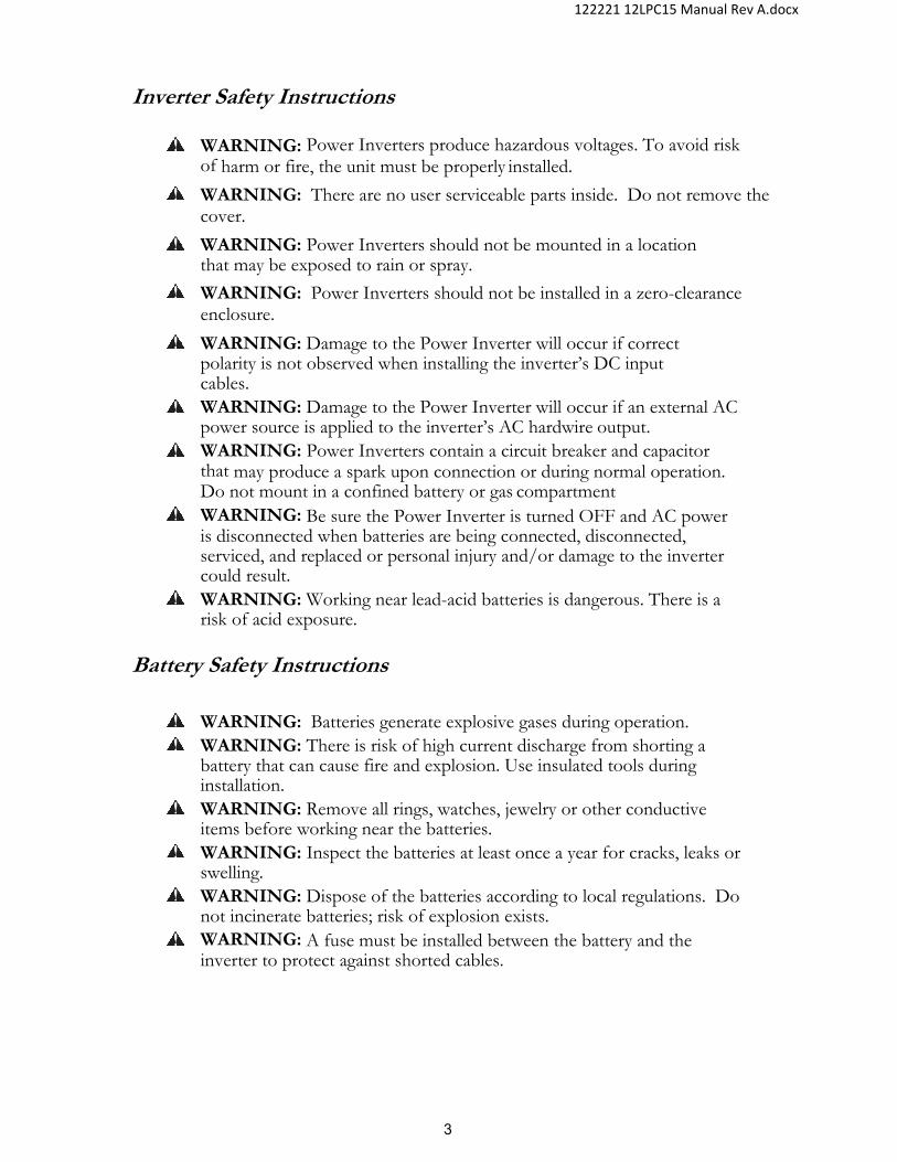
Inverter Safety Instructions
WARNING: Power Inverters produce hazardous voltages. To avoid risk of harm or fire, the unit must be properly installed.
WARNING: There are no user serviceable parts inside. Do not remove the cover.
WARNING: Power Inverters should not be mounted in a location that may be exposed to rain or spray.
WARNING: Power Inverters should not be installed in a zero-clearance enclosure.
WARNING: Damage to the Power Inverter will occur if correct polarity is not observed when installing the inverter’s DC input cables.
WARNING: Damage to the Power Inverter will occur if an external AC power source is applied to the inverter’s AC hardwire output.
WARNING: Power Inverters contain a circuit breaker and capacitor that may produce a spark upon connection or during normal operation. Do not mount in a confined battery or gas compartment
WARNING: Be sure the Power Inverter is turned OFF and AC power is disconnected when batteries are being connected, disconnected, serviced, and replaced or personal injury and/or damage to the inverter could result.
WARNING: Working near lead-acid batteries is dangerous. There is a risk of acid exposure.
Battery Safety Instructions
WARNING: Batteries generate explosive gases during operation. WARNING: There is risk of high current discharge from shorting a
battery that can cause fire and explosion. Use insulated tools during installation.
WARNING: Remove all rings, watches, jewelry or other conductive items before working near the batteries.
WARNING: Inspect the batteries at least once a year for cracks, leaks or swelling.
WARNING: Dispose of the batteries according to local regulations. Do not incinerate batteries; risk of explosion exists.
WARNING: A fuse must be installed between the battery and the inverter to protect against shorted cables.
4
122221 12LPC15 Manual Rev A.docx
TABLE OF CONTENTS
INTRODUCTION ............................................................................................ 2 Important ............................................................................................ 2
SAFETY LISTING ........................................................................................... 2 Inverter Safety Instructions ................................................................ 3 Battery Safety Instructions ................................................................. 3
TABLE OF CONTENTS .................................................................................. 4 SPECIFICATIONS .......................................................................................... 6 OTHER DESIGN FEATURES ........................................................................ 6 PHYSICAL DESCRIPTION ............................................................................. 7 MOUNTING THE INVERTER ......................................................................... 8
Installation Tools ................................................................................ 8 Inverter Mounting Recommendations ................................................ 8
DC WIRE GAUGE & FUSING ........................................................................ 9 Inverter Cable .................................................................................... 9
WIRING DIAGRAM ....................................................................................... 11 Typical DC Wiring Diagram.............................................................. 11
AC INPUT/OUTPUT CONNECTIONS .......................................................... 12 GFCI: ................................................................................................ 12 Hardwire Interface: ........................................................................... 12
REMOTE INVERTER ON/OFF SWITCH ..................................................... 14 Remote Inverter ON/OFF Switch – Customer Supplied ..................... 14
OPERATION ................................................................................................. 15 Inverter Power Mode ........................................................................ 15 External Power Mode - Bypass ....................................................... 15 External Power Mode -Battery Charger ........................................... 15
CONFIGURATIONS ..................................................................................... 16 Default Configuration ........................................................................ 16 Switch Options .................................................................................. 17 Low Battery Shutdown ...................................................................... 17 Shutdown Timer ............................................................................... 17 Sleep Mode (Load Sense) ................................................................ 17 Auxiliary Control ............................................................................... 18 Battery Options ................................................................................. 18 Branch Circuit Rating (LPC only) ...................................................... 19 AC Line Qualify Time (LPC only) ...................................................... 19 CAN Instance and Baud Rate ........................................................... 19
INVERTER CONFIGURATION TOOL .......................................................... 20 THEORY OF OPERATION ........................................................................... 21
Inverter ............................................................................................. 21 External Power Mode (LPC only) .................................................... 22
TROUBLESHOOTING GUIDE ..................................................................... 26

5
122221 12LPC15 Manual Rev A.docx
LED Status Chart .............................................................................. 26 Faults and Warnings - Inverter .......................................................... 27 Faults and Warnings - Charger ........................................................ 28 Troubleshooting ................................................................................ 29
APPENDIX .................................................................................................... 30 Accessories & Replacement Parts .................................................... 30 GFCI Operation ................................................................................ 30 Inverter Model Options ..................................................................... 31 Other options available, contact the factory for more information. .. 31 3 Step Battery Charger Recipes with BTS ....................................... 32 Charger Output vs. Temperature ..................................................... 33 CAN .................................................................................................. 34
LIMITED WARRANTY TERMS & CONDITIONS ......................................... 37 Figure 1 - Features ............................................................................................ 7 Figure 2 - Mounting for all models (units are in inches) .................................... 8 Figure 3 - Proper installation of cable into DC terminal cover ........................ 10 Figure 4 - DC Input Wiring .............................................................................. 11 Figure 5 - Hardwire access ............................................................................. 12 Figure 6 - AC Inverter Output Connections..................................................... 13 Figure 7 - AC Input for Charger/Bypass .......................................................... 13 Figure 8 - 12LP15R shown with snap switch .................................................. 14 Figure 9 - Aux Connection .............................................................................. 18 Figure 10 - Temp Derating .............................................................................. 21 Figure 11 - Load Management ........................................................................ 22 Figure 12 - BTS ............................................................................................... 24 Figure 13 - Charger Voltage Adjustment ........................................................ 25 Figure 14 - Charger Output vs. Temp ............................................................. 33 Figure 15 - Communications ........................................................................... 35 Table 1 – Specs ................................................................................................ 6 Table 2 - Cable Sizing ....................................................................................... 9 Table 3 - Charge Modes ................................................................................. 15 Table 4 - Configurations and Defaults ............................................................ 16 Table 5 - Switch Options ................................................................................. 17 Table 6 - Aux Control ...................................................................................... 18 Table 7 - LED Status ....................................................................................... 26 Table 8 - Accessories ...................................................................................... 30 Table 9 - GFCI Replacements ........................................................................ 31 Table 10 - Options ........................................................................................... 31 Table 11 - Charger Recipe .............................................................................. 32 Table 12 - CAN Command .............................................................................. 34 Table 13 - CAN Status .................................................................................... 34
6
122221 12LPC15 Manual Rev A.docx
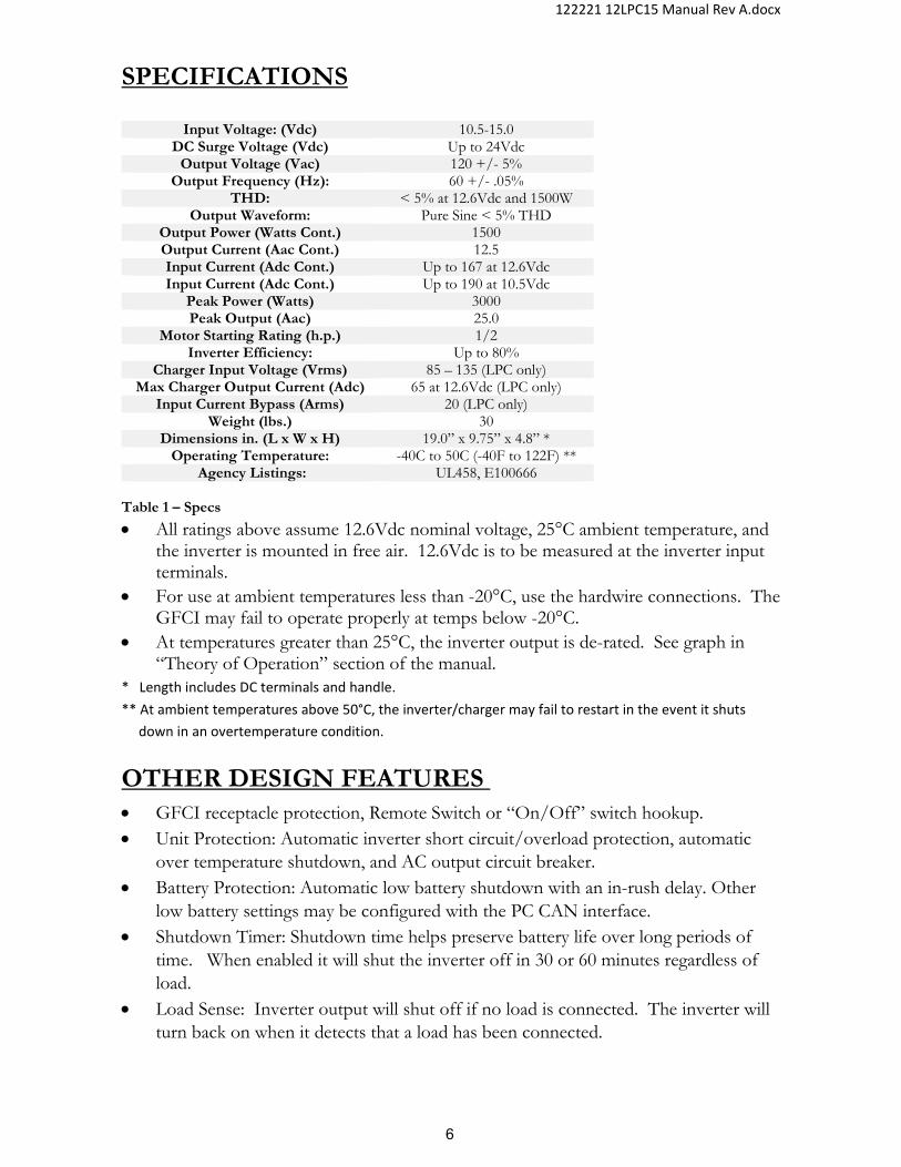
SPECIFICATIONS
Input Voltage: (Vdc) 10.5-15.0 DC Surge Voltage (Vdc) Up to 24Vdc
Output Voltage (Vac) 120 +/- 5% Output Frequency (Hz): 60 +/- .05%
THD: < 5% at 12.6Vdc and 1500W Output Waveform: Pure Sine < 5% THD
Output Power (Watts Cont.) 1500 Output Current (Aac Cont.) 12.5 Input Current (Adc Cont.) Up to 167 at 12.6Vdc Input Current (Adc Cont.) Up to 190 at 10.5Vdc
Peak Power (Watts) 3000 Peak Output (Aac) 25.0
Motor Starting Rating (h.p.) 1/2 Inverter Efficiency: Up to 80%
Charger Input Voltage (Vrms) 85 – 135 (LPC only) Max Charger Output Current (Adc) 65 at 12.6Vdc (LPC only)
Input Current Bypass (Arms) 20 (LPC only) Weight (lbs.) 30
Dimensions in. (L x W x H) 19.0” x 9.75” x 4.8” * Operating Temperature: -40C to 50C (-40F to 122F) **
Agency Listings: UL458, E100666
Table 1 – Specs
All ratings above assume 12.6Vdc nominal voltage, 25°C ambient temperature, and the inverter is mounted in free air. 12.6Vdc is to be measured at the inverter input terminals.
For use at ambient temperatures less than -20°C, use the hardwire connections. The GFCI may fail to operate properly at temps below -20°C.
At temperatures greater than 25°C, the inverter output is de-rated. See graph in “Theory of Operation” section of the manual.
* Length includes DC terminals and handle.
** At ambient temperatures above 50°C, the inverter/charger may fail to restart in the event it shuts
down in an overtemperature condition.
OTHER DESIGN FEATURES GFCI receptacle protection, Remote Switch or “On/Off” switch hookup. Unit Protection: Automatic inverter short circuit/overload protection, automatic
over temperature shutdown, and AC output circuit breaker. Battery Protection: Automatic low battery shutdown with an in-rush delay. Other
low battery settings may be configured with the PC CAN interface. Shutdown Timer: Shutdown time helps preserve battery life over long periods of
time. When enabled it will shut the inverter off in 30 or 60 minutes regardless of load.
Load Sense: Inverter output will shut off if no load is connected. The inverter will turn back on when it detects that a load has been connected.

7
122221 12LPC15 Manual Rev A.docx
PHYSICAL DESCRIPTION
(1) GFCI: Provides 120VAC output. Only replace with an approved GFCI. (2) Status LED: This LED will show inverter operation mode and troubleshooting
information. See the table in the troubleshooting section at the rear of the manual for further operation mode descriptions.
(3) Local On/Off: This switch turns the inverter on or off. **Switch inoperable for "HR" and "R" configurations.
(4) AC Input and Output Breakers: Input and output breakers. Protects the inverter from output short circuits and overloads. The 12LP15 (inverter only) only uses a 15A output breaker. The 12LPC15 (inverter/charger) uses 20A input and output breakers. The input breaker position for the 12LP15 is plugged.
(5) Bonding lug: Connects to the system ground. (6) DC input connections: Connects to the battery bank. (7) Remote On/Off Wiring Tab: Terminal is used to wire a customer supplied
remote ON/OFF switch. Apply battery voltage to tab to turn on inverter. (8) Aux Wiring Tab: Terminal is used to enable internal housekeeping power
only. Apply battery voltage to enable. Does not turn on inverter output. (9) AC Wiring Access Plate: Provides wiring and inspection access to AC output
terminals inside the AC wiring box. To be closed during operations. (10) Various Ports: “CAN” is used for connection of a CAN interface. “TEMP
SENSE” is used for connection a battery temperature sensor (BTS), sold separately. “ACC” is used for a remote switch (purchased separately). The Sync port may be plugged with an empty connector because it is currently not used.
Figure 1 - Features
77 88 33 22 9 1
66
1010
55 4

8
122221 12LPC15 Manual Rev A.docx
MOUNTING THE INVERTER
Installation Tools
The following tools may be required for inverter installation: Crimper, Cable Ties, Cutter, Drill, #2 Phillips Screw Driver (with a magnetic end), Slotted Screw Driver, Tape Measure, Wire Cutters, Needle Nose Pliers, and Wire Strippers.
Inverter Mounting Recommendations
NOTE: The inverter mounting location should provide adequate ventilation and clearance to maintain room temperature during operation. At least ½” of clearance is required on all sides except the bottom.
1. Locate a suitable, secure mounting surface as close to the batteries as possible without being in the same compartment.
2. Mount the inverter using four each ¼-20 steel bolts, flat and lock washers, and nuts. The length of the bolts should be equal to the mounting material thickness plus ¾”.
Figure 2 - Mounting for all models (units are in inches)

9
122221 12LPC15 Manual Rev A.docx
DC WIRE GAUGE & FUSING
Inverter Cable
An “Inverter Cable Kit” (positive cable, negative cable, and proper fuse) is needed to connect the inverter to a battery bank. An 8-gauge wire is also recommended to connect the inverter’s bonding lug to system ground.
Use a 1/0 cable to connect to the inverter. The recommended maximum length of the inverter cable is 15-ft, and it must be fused within 18 inches of the positive (+) terminal of the battery.
An inverter cable kit designed to SAE guidelines can be purchased directly from Sensata – call for options.
Torque the DC connections on the inverter to 50-60 lbs.-in.
Torque the inverter bonding lug to 45 lbs.-in. for 6AWG or 40 lbs.-in. for 8AWG.
Min. Cable and Max. Fusing Guide for 3% Voltage Drop at 100%
Output. Inverter Model
Full Load (Adc) Inverter to Battery Est. Cable Length in Feet
up to 15 feet @ 25°C (77°F)
12LP15/ 12LPC15
190Adc 100% Duty (at 10.5Vdc)
1/0 AWG, 350A Fuse
12LP15/ 12LPC15
190Adc 50% Duty (at 10.5Vdc)
1/0 AWG, 350A Fuse
Table 2 - Cable Sizing
NOTE: Using a smaller cable may cause the inverter to go into low battery or high temperature prematurely.
NOTE: 100% duty rating assumes the inverter is operating at its full rated output power continuously for at least an hour. The 50% duty rating assumes that the inverter is operating at its full rated output power for up to 15 minutes and then operating with a load less than 25% of its full rating for at least 15 minutes before returning to full power and repeating. Alternately it can also operate at 50% of its rated output power continuously. Table assumes operating in an ambient temperature of 25°C (77°F). For higher ambient temperatures, additional derating may be required (i.e. may need to use a larger cable size).

10
122221 12LPC15 Manual Rev A.docx
To make your own “Inverter Cable Kit,” follow the below recommendations:
1. Use 1/0-ga stranded copper cables in all cases. 2. USE SGX cross-linked polyurethane insulation type that complies with the high
temperature insulation requirements (125°C.) of SAE J-1127 and vehicle manufacturer requirements.
3. For 1/4" ring lugs, use JST 38-S6. TIP: It is useful to use a needle nose pliers to help insert or remove the 1/4x20 screw
and toothed washer.
Figure 3 - Proper installation of cable into DC terminal cover

11
122221 12LPC15 Manual Rev A.docx
WIRING DIAGRAM
Typical DC Wiring Diagram
12.6VdcBATTERY
FUSE
TO CHASSISGROUND
Cable Connection Procedure Remove the fuse from the fuse holder. Connect the inverter’s bonding lug to ground of the vehicle chassis. Connect the ring terminated end of the black inverter cable set directly
to the (-) Negative side of the battery bank at a negative battery post. Connect the fuse holder to the (+) Positive side of the battery bank. Connect the ring terminated end of the RED inverter cable set directly
to the fuse holder. Install the fuse in the fuse holder. A typical one-time spark will occur
when this final connection is made. Install the fuse holder cover.
Figure 4 - DC Input Wiring

12
122221 12LPC15 Manual Rev A.docx
AC INPUT/OUTPUT CONNECTIONS
WARNING: Do not connect another source of AC power directly to the AC output of the inverter. This will result in damage not covered under warranty.
GFCI: A 20A GFCI is installed into the side of the inverter, except for “H” suffix hardwire only versions where it is omitted. The rated output of the inverter is 12.5A. If a 20A load is applied to the GFCI, the 15A AC output breaker installed on a 12LP15 inverter only will eventually trip. The 12LPC15 allows for 20A of bypass current, so a 20A breaker is used. If 20A of load is connected to the inverter or inverter/charger while in inverter mode, the inverter will shut down in overload.
Hardwire Interface: Remove the cover for hardwire AC wiring. Insert AC input and output wiring through the AC Output cable clamps to protect the wires from the metal edge of the hole. Connect the AC wiring to the provided internal terminal blocks. Be sure to connect the AC input wiring to the AC input terminal blocks, and the AC output wiring to the AC output terminal blocks. The AC terminal block will accept 14-8 AWG wire. Proper torque for the AC terminal blocks is 10lbs.-in. The 12LP15 should use 14AWG minimum for the AC output. The 12LPC15 should use 12AWG minimum for the AC input and AC output. Connect the hot wires to the black terminal, the neutral to the white terminal, and the ground to the green terminal.
Remove these screws to access terminal blocks for hardwire connections.
Remove these screws to access terminal blocks for hardwire connections.
Figure 5 - Hardwire access

13
122221 12LPC15 Manual Rev A.docx
NOTE: The AC input should be protected by a 20A branch rated breaker external to the inverter/charger.
NOTE: The AC output should be protected by a branch rated breaker external to the inverter if required to comply with the National Electric Code, NFPA 70.
NOTE: Connecting the AC inverter input to a GFCI protected outlet may cause some interference with the inverter’s GFCI.
Connect inverter AC output wires here. Black is AC hot, white is AC neutral, and green is ground.
Connect charger AC input wires here. Black is AC hot, white is AC neutral, and green is ground.
Figure 7 - AC Input for Charger/Bypass
Figure 6 - AC Inverter Output Connections

14
122221 12LPC15 Manual Rev A.docx
REMOTE INVERTER ON/OFF SWITCH
Remote Inverter ON/OFF Switch – Customer Supplied Two types of remote switches may be used to control the inverter/charger. They are momentary or snap switches. However, the type of switch used can only be used in specific circumstances. For non “-R” suffix versions, a momentary switch must be used. For remote only “-R” suffix versions, a snap switch must be used. If a snap switch is used in place of a momentary switch, the inverter may not respond correctly. In remote only mode, the snap switch will turn the inverter on and off when in inverter mode. When in charger mode, it will switch the inverter state between off and standby. In non-remote only mode, the momentary switch will toggle the inverter state between on and off, or standby and off while in charge mode. The remote switch may be customer supplied or ordered separately from the factory. Mount the remote switch in a convenient location. Using 18-gauge wire and an insulated ¼” female faston, wire between the “Remote ON/OFF” connection on the left side of the inverter. Wire from the remaining connection on the remote switch to the battery positive (+) terminal. Be sure to install a 5-amp in-line fuse in series within 10 inches from the positive (+) terminal of the battery.
Figure 8 - 12LP15R shown with snap switch
12.6VdcBATTERY
FUSE REMOTE ON/OFF SWITCH
CONNECT TO “REMOTE ON/OFF” TAB
12.6VdcBATTERY
FUSE REMOTE ON/OFF SWITCH
CONNECT TO “REMOTE ON/OFF” TAB

15
122221 12LPC15 Manual Rev A.docx
OPERATION
Once the inverter has been fully installed and wired, and DC power has been applied, the inverter is ready to turn on. The Status LED beneath the AC wiring box on the left side of the inverter shows the current state of the inverter.
Inverter Power Mode
The inverter can now be turned on by using the local or remote switch. When the inverter is on, the local Status LED will be a constant green. When the Local On/Off switch is enabled in assemblies without the “R” suffix, any switch may turn on or off the inverter. When using the local switch, any remote switch must be a momentary type. With the “R” suffix, only the remote switch will turn on the inverter. The remote switch must be a snap type. The Local On/Off switch will be inactive. The function of the switch will depend on the mode the unit is running in, and if the Aux tab is enabled and being used.
Note: The LED will blink a yellow-green pattern indicating the battery type on the
12LPC15 during the first 5 minutes of operation upon initial power-up. The pattern will cease if a warning or fault occurs.
External Power Mode - Bypass The loads attached to the inverter output will operate directly from the external AC power line independently of the inverter ON/OFF status. If the inverter is left ON (standby mode), the built-in bypass relay will automatically cycle back and forth between “Inverter Power” mode and “External Power” mode depending on the availability of the external AC power line.
External Power Mode -Battery Charger The battery charger will engage automatically and independently of the inverter ON/OFF status. The 3-step charging process modes are: Constant Current (Bulk), Constant Voltage (Acceptance), and Float. The Battery Temperature Sensor (BTS) must be plugged into the “TEMP SENSE” connector on the inverter. If not, the charger will not operate.
Charging Status LED Normal States LED Color LED State Operating Conditions
Green 1 blink Constant Current (Bulk) Charge Green 2 blinks Constant Voltage (Accept) Charge Green 3 blinks Float Charge Green 4 blinks Load Management Active
Table 3 - Charge Modes

122221 12LPC15 Manual Rev A.docx
CONFIGURATIONS
Default Configuration DEFAULT SETTINGS
MODEL Local Switch
Remote Switch Low
Battery Shut Down
Timer Load Sense
Aux Control Battery Type Branch Circuit
Rating AC Line Qualify
CAN Instance
CAN Baud Rate
LP STANDARD ENABLED MOMENTARY 10.5 V OFF OFF DISABLED N/A N/A N/A 1 250k
LP WITH "R" SUFFIX
DISABLED SNAP 10.5 V OFF OFF DISABLED N/A N/A N/A 1 250k
LPC STANDARD ENABLED MOMENTARY 10.5 V OFF OFF DISABLED AGM 15A 30 SECS 1 250k
LPC WITH "R" SUFFIX
DISABLED SNAP 11.0 V OFF OFF DISABLED AGM 20A 30 SECS 1 250k
OPTIONS
SETTING OPTIONS (SET BY CAN PROGRAMMING TOOL OR FACTORY)
Local Switch
Remote Switch Low
Battery Shut Down
Timer Load Sense
Aux Control Battery Type Branch Circuit
Rating AC Line Qualify
CAN Instance
CAN Baud Rate
ENABLED MOMENTARY 10.5 OFF ON DISABLED WET LEAD ACID DISABLED 5 SECS 1 250k
DISABLED SNAP to 30 MINUTES
OFF RV AGM 5A to to 500k
12.0V 60 MINUTES
UTILITY GEL to 30 SECS 13
CUSTOM
20A
INCREMENT
0.1V
STEPS
5A STEPS 5 SEC
STEPS
Table 4 - Configurations and Defaults
17
122221 12LPC15 Manual Rev A.docx
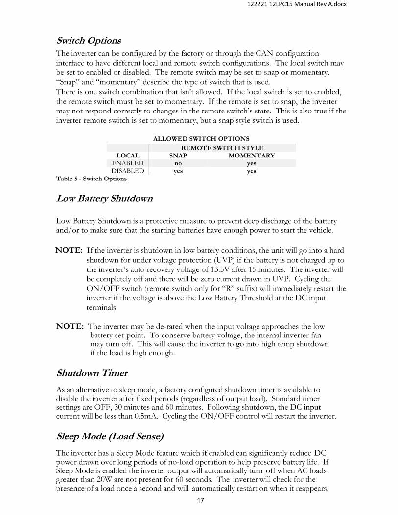
Switch Options The inverter can be configured by the factory or through the CAN configuration interface to have different local and remote switch configurations. The local switch may be set to enabled or disabled. The remote switch may be set to snap or momentary. “Snap” and “momentary” describe the type of switch that is used. There is one switch combination that isn’t allowed. If the local switch is set to enabled, the remote switch must be set to momentary. If the remote is set to snap, the inverter may not respond correctly to changes in the remote switch’s state. This is also true if the inverter remote switch is set to momentary, but a snap style switch is used.
ALLOWED SWITCH OPTIONS
REMOTE SWITCH STYLE LOCAL SNAP MOMENTARY
ENABLED no yes DISABLED yes yes
Table 5 - Switch Options
Low Battery Shutdown
Low Battery Shutdown is a protective measure to prevent deep discharge of the battery and/or to make sure that the starting batteries have enough power to start the vehicle.
NOTE: If the inverter is shutdown in low battery conditions, the unit will go into a hard
shutdown for under voltage protection (UVP) if the battery is not charged up to the inverter’s auto recovery voltage of 13.5V after 15 minutes. The inverter will be completely off and there will be zero current drawn in UVP. Cycling the ON/OFF switch (remote switch only for “R” suffix) will immediately restart the inverter if the voltage is above the Low Battery Threshold at the DC input terminals.
NOTE: The inverter may be de-rated when the input voltage approaches the low
battery set-point. To conserve battery voltage, the internal inverter fan may turn off. This will cause the inverter to go into high temp shutdown if the load is high enough.
Shutdown Timer
As an alternative to sleep mode, a factory configured shutdown timer is available to disable the inverter after fixed periods (regardless of output load). Standard timer settings are OFF, 30 minutes and 60 minutes. Following shutdown, the DC input current will be less than 0.5mA. Cycling the ON/OFF control will restart the inverter.
Sleep Mode (Load Sense)
The inverter has a Sleep Mode feature which if enabled can significantly reduce DC power drawn over long periods of no-load operation to help preserve battery life. If Sleep Mode is enabled the inverter output will automatically turn off when AC loads greater than 20W are not present for 60 seconds. The inverter will check for the presence of a load once a second and will automatically restart on when it reappears.

18
122221 12LPC15 Manual Rev A.docx
NOTE: While in sleep mode it may take up to one second for the load to receive power when the load is applied.
NOTE: The LED on the GFCI will blink when the inverter has gone to sleep.
Auxiliary Control The “AUX” tab on the side of the inverter allows for additional functionality of the inverter. The “AUX” tab is set to disabled by default at the factory. To change it, contact the factory or use the CAN Setup Tool. To use the AUX tab, battery voltage needs to be applied to it. The connection should be fused.
Mode Description of Mode
Disabled Aux tab doesn't do anything. Utility Aux tab required to be high to enable inverter, charger,
and bypass. RV Aux tab required to be high to enable inverter. Charger
and bypass not affected. Control Aux tab required to be high to enable charger mode.
Inverter and bypass not affected. Table 6 - Aux Control
The “AUX” tab has no effect on charger and bypass functions if enabled on a 12LP15 inverter only. Note: Applying battery voltage to the “AUX” tab while the inverter is off will cause the
inverter to draw about 170mA. Remove power from the “AUX” tab when not using the inverter to conserve battery power.
Figure 9 - Aux Connection
Battery Options The charger can be set to charge three different types of batteries. Wet Lead Acid, AGM, or Gel. The charger is set to Wet Lead Acid by default by the factory. The battery type may be changed at the factory or by the CAN configuration interface. To determine what type of battery the inverter is configured for, monitor the LED blink code at startup. If the inverter is configured for Wet Lead Acid, the LED will blink Amber-Green. For
REMOTE IGNITIONSWITCH
12 VdcBATTERY
FUSE
REMOTE IGNITIONSWITCH
12 VdcBATTERY
FUSE
19
122221 12LPC15 Manual Rev A.docx
AGM the blink code is Amber-Green-Green. For Gel the blink code is Amber-Green-Green-Green.
Branch Circuit Rating (LPC only) The branch circuit rating (“BCR”) can be set to 0, 5, 10, 15, or 20A. If set to 0A, the charger will not enable. Bypass will still be available. The default factory setting is 15A. The BCR may be changed at the factory or by the CAN configuration interface.
AC Line Qualify Time (LPC only) The AC line qualification time can be set to any value between 5 and 60 seconds, in 1 second increments. This default setting is 30 seconds. This setting adjusts the time that it takes for the charger and bypass to start once qualified AC power has been applied to the charger input. This setting may be changed at the factory or with the CAN configuration interface.
CAN Instance and Baud Rate The CAN instance (address) can be changed from 1 – 13. This is useful if there are multiple inverters being used on the same CAN network. Multiple inverters should not share the same CAN instance. The Baud Rate may be changed between 250k and 500k. The default settings for the inverter are Instance 1 and Baud Rate 250k. These values may be changed at the factory or by the CAN configuration interface.
NOTE: In the highly unlikely chance that an internal error occurs to the memory of the inverter/charger, the inverter/charger configuration will reset to the 12LPC15 standard. All settings will revert to the standard default configuration, except the battery setting will be set to GEL.
20
122221 12LPC15 Manual Rev A.docx
INVERTER CONFIGURATION TOOL
The inverter/charger settings described in the previous section may be adjusted with a CAN interface kit, which is sold separately. The kit consists of a Kvaser CAN interface which connects to a USB port on a laptop, a DB9 to RJ45 adapter, a terminating resistor, and a Windows PC program that can be installed on a x32 or x64 machine. After the software has been properly installed, the Kvaser device may be plugged into the computer. The first time the Kvaser is connected, the computer may need to download the appropriate Kvaser drivers from the Kvaser website. Once the Kvaser device is ready to be used, the terminating resistor and DB9 to RJ45 adapter may be connected to the inverter CAN port. Once the inverter is turned on, the Configuration Interface may be opened on the laptop. Once open, the tool will automatically look for a CAN device on the network. Once found, it will automatically connect and display the current inverter/charger settings. Note: Only one CAN enabled inverter can be connected at a time. To make a settings
change, click on a parameter and the available options will appear in a drop-down menu. Once a setting is changed, the change is immediately set into the inverter’s memory. After making all the settings changes it is prudent to turn the inverter off for 30 seconds and then turn it back on for the setting changes to take effect.
The settings may be saved to a configuration file. The configuration file maybe used to program any additional units that are to be programmed with the same settings.

21
122221 12LPC15 Manual Rev A.docx
THEORY OF OPERATION
Inverter Usage: Any 120 VAC, 60 Hz single phase product within the inverter’s power rating.
The inverter front “STATUS” LED will be Green while the inverter is on. The AC power produced by the inverter comes from the energy stored in the battery bank through a sophisticated electronic inversion process. A transformer, a Metal Oxide Silicon Field Effect Transistors (MOSFET), a filter capacitor, and a microprocessor are used to generate clean AC power. The inverter will operate at DC input voltages ranging from 10.5Vdc to 16 Vdc. Above 16 Vdc the inverter may stop operating due to input voltage being out of range. The inverter can tolerate up to 24 Vdc for 5 minutes. Durations longer than 5 minutes will result in a shut down. Input voltages above 24Vdc will result in an immediate shutdown. The inverter will restart when the input voltage drops below 16 Vdc. When the input voltage drops to the low battery volts, the inverter will stop operating due to a low battery condition. When the lead acid battery bank voltage drops to 10.5 volts, the battery is fully discharged.
Note: The signal output waveform produced by the inverter when in “inverter mode” is
pure sinusoidal. It has a total harmonic distortion of less than 5% at nominal input.
The inverter output needs to be de-rated as the ambient temperature surrounding it increases. See the following chart for operation at 12.6 Vdc.
800 W
900 W
1000 W
1100 W
1200 W
1300 W
1400 W
1500 W
75°F 85°F 95°F 105°F 115°F 125°F
12LPC15 TEMP DERATING at 12.6 Vdc
Figure 10 - Temp Derating

22
122221 12LPC15 Manual Rev A.docx
External Power Mode (LPC only) Bypass Relay: The loads attached to the inverter output will operate directly from the external AC power line independently of the inverter ON/OFF status. If the inverter is left ON (standby mode), the built-in bypass relay will automatically cycle back and forth between “Inverter Power” mode and “External Power” mode depending on the availability of the external AC power line. Note: If the AC load is short-circuited while in bypass mode, the inverter/charger may
experience an internal fault. Battery Charger: The battery charger will engage automatically and independently of the inverter ON/OFF status. The 3-step charging process modes are; Constant Current (Bulk), Constant Voltage (Acceptance), and Float. There are three additional states the charger may enter: Load Management, Equalization, and Monitor The LED Display Panel will show charger mode and the Status LED located on the side of the inverter will blink Green to indicate the charging process mode (1 blink = Constant Current, 2 blinks = Constant Voltage, 3 blinks = Float). See the LED blink code chart for additional blink codes.
Constant Current (Bulk): The charger will output the maximum rated current to the battery until the battery voltage (as measured at the charger DC terminals) reaches the maximum voltage threshold or the Constant Current timer expires.
Constant Voltage (Acceptance): The charger will output at the rated voltage until the output current reaches nearly zero or the Constant Voltage time expires.
Float: The charger will output current and voltage at the minimum duty cycle until the voltage drops below a threshold.
Load Management: Incoming AC power is shared between the AC loads and the charger. The AC loads are given priority; this means the charger will reduce its output with large AC loads. This feature controls the total amperage draw of the system so the utility service circuit breaker is not tripped. The Load Management feature will return the charger to full output when the AC loads are removed or reduced.
BYPASS CURRENT
INPUT CURRENT
BCR SETTING 0 – 20A. SET BY CAN, OR DEFAULT
VALUE
CURRENT TO CHARGER
Figure 11 - Load Management

23
122221 12LPC15 Manual Rev A.docx
The charger splits the input current to the charger and to the AC output. The charger will limit the amount of current flowing to battery based on the AC current limit setting. If the total input current exceeds the limit setting, the charge current will be reduced until the limit is met. If the bypass current exceeds the limit setting, the charger will not output current to the battery. The default AC current limit is set by the factory to 15A. NOTE: Dynamic external loads may cause variations in the charge rate. The charger
may reset if the dynamic load causes the input AC waveform to become temporarily disqualified.
Equalization: Available only for wet-lead-acid batteries, this function overcharges the battery in a controlled fashion to remove sulphate build up from the battery’s internal plates. Consult your battery manufacturer on how frequently the equalization process should be carried out. Equalization can only be initiated with a RV-C CAN command. The process will not start until a full charge cycle has been completed.
Monitor: In this mode, the charger stops charging at the end of a charge cycle. It keeps track of the battery voltage to decide when and if it needs to restart a charge cycle.
NOTE: When in charge mode, the charger may not be able to charge at its full capacity if AC power is being used in bypass mode.
NOTE: The charger is capable of charging AGM, GEL, or Wet Lead-Acid cell batteries. Selection of battery type must be done when ordering the inverter from the factory. The battery type may also be set with the CAN interface or via RV-C CAN. Contact factory for further details on RV-C CAN.

24
122221 12LPC15 Manual Rev A.docx
Charger Battery Temperature Sensor (BTS): Charger operation with a BTS cable is REQUIRED! The BTS measures the battery temperature and automatically adjusts the charger output voltage for the fastest and safest charge. When batteries are cold, their chemical reaction is slowed, so they will not take on a charge as easily. A charge voltage optimized for room temperature will not charge the battery at low temperatures. The temp sensor cable allows the charger to increase the charge voltage for optimum charging at low temperatures. When batteries are hot, their chemical reaction is accelerated and they absorb energy too readily. A charge voltage optimized for room temperature will tend to overcharge the batteries and cause gassing. The BTS will cause the charger to decrease the charge voltage to a safe level. Our charger will switch to a “warm battery” mode in which the charger will only provide a float voltage when the batteries reaches 122F/50C to 140F/60C. If the battery temperature continues to rise over 140F/60C the charger will shut off. The charger will resume charging in the “warm battery” mode when the battery cools to 131F/55C. The charger will resume normal charging when the battery cools to 113F/45C.
Connect the lug end of the temperature compensation cable to the negative post of the battery. Connect the connector to the appropriate mating connector located at the side of the inverter labeled “Temp Sense”. Temp Sensor cable is part# ME-BTS-XX
Figure 12 - BTS

25
122221 12LPC15 Manual Rev A.docx
(XX=length in feet - 6, 8, 15, 25, 40)
NOTE: If the Temp. Sensor Cable is not connected; the battery charger will not function
‐0.75
‐0.60
‐0.45
‐0.30
‐0.15
0.00
+0.15
+0.30
+0.45
+0.60
+0.75
32°F 41°F 50°F 59°F 68°F 77°F 86°F 95°F 104°F 113°F 122°F 131°F 140°F
Change to battery charging voltage
Temperature reading from BTS
Temperature Compensation using BTS
Figure 13 - Charger Voltage Adjustment

26
122221 12LPC15 Manual Rev A.docx
TROUBLESHOOTING GUIDE
WARNING: Do not remove chassis cover. No user-serviceable parts inside. Call or e-mail customer service for free consultation during business hours. Business hours are 7:30am-5:30pm C.S.T
Phone: 1-800-553-6418 or 1-651-653-7000
Fax: 1-888-439-3565 or 1-651-653-7600
E-mail: [email protected];
Website: http://dimensions.sensata.com
LED Status Chart
Status LED Normal States LED Color & State Remote LED State Operating Conditions Green – 1 blink Constant on Bulk Charge (Constant Current) Green – 2 blinks Constant on Accept Charge (Constant Voltage) Green – 3 blinks Constant on Float Charge Green – 4 blinks Constant on Load Management Active Green – 5 blinks Constant on Equalization Mode Green – 6 blinks Constant on Monitor Mode Green ‐ Solid Constant on Inverting
Inverter Status LED Fault States None Off No Power to Unit or Internal Fault
Amber ‐ Solid Constant on Low Battery 0‐5 seconds (warning) Red ‐ Solid Constant on Overload 0‐5 seconds (warning) Red‐ 1 blink 1 blink Inverter Low Battery Shut Down** Red – 2 blinks 2 blinks Inverter Overload Shut Down Red – 3 blinks 3 blinks High Temp Heatsink* Red – 4 blinks 4 blinks Feedback Fault, Output Short Circuit** Red – 5 blinks 5 blinks High Battery 0‐5 minutes Red – 6 blinks 6 blinks High Battery > 5 minutes Red – 7 blinks 7 blinks High Temp Transformer Red – 8 blinks 8 blinks Inverter Off by CAN
Charger Status LED Fault States None Off No Power to Unit or Internal Fault
Amber‐ 1 blink Fast blink Charger Off – Check Battery Probe Amber – 2 blinks Fast blink Charger – Warm Battery* Amber – 3 blinks Fast blink Charger Off – High Battery Voltage* Amber – 4 blinks Fast blink Charger Off – High Batt Temp Amber – 5 blinks Fast blink Charger Off – Low Battery Voltage Amber – 6 blinks Fast blink Charger Off – High Temp Transformer* Amber – 7 blinks Fast blink Charger Off – High Temp Heatsink* Amber – 8 blinks Fast blink Charger Off – 0 Amp Limit Set Amber – 9 blinks Fast blink Charger Off –Overcurrent Shutdown Amber – 10 blinks Fast blink Charger Off – Disabled by CAN
Faults marked with* will self‐recover when the condition returns to normal range Faults marked with ** may be due to a short‐circuited output or a low or weak DC voltage source.
Battery Type Local LED States at Start‐up (5 Minutes) Amber ‐ Green Wet Lead‐Acid
Amber – Green ‐ Green AGM Amber – Green ‐ Green ‐ Green GEL
Table 7 - LED Status
Note: Upon initial start-up, the inverter will blink amber and green to identify the type of battery it is configured for.
27
122221 12LPC15 Manual Rev A.docx
Faults and Warnings - Inverter
Low Battery – The inverter LED will switch to solid Amber when the DC voltage measured at the inverter input terminals drops below the low battery setpoint. After five seconds, the inverter will shut down if the DC voltage has not recovered above the low battery setpoint. When shut down, the inverter LED will blink Red. The inverter will automatically restart if the battery voltage rises above a preset threshold within 15 minutes. If the battery voltage does not recover within 15 minutes, the inverter will completely shut-down and the inverter will need to be turned off then on with a local or remote switch.
Overload – The inverter LED will switch to a solid red when an overload condition is detected. If the overload condition clears within 5 seconds the LED will return to the normal state. If the overload condition continues after 5 seconds, the inverter will shut down and the LED will blink red twice. The inverter power will need to be cycled to restart the inverter. If the overload condition exceeds 108% of the rated load for greater than 1.5 seconds, the inverter will shut down and the LED will blink red twice. The inverter power will need to be cycled to restart the inverter. If the overload condition exceeds 200% of rated load, the inverter will shut down immediately. Note: The inverter will only permit an overload event to exceed 108% of rated load
once every 30 seconds. For example, the inverter may go into overload when starting up a compressor. 30 seconds must pass before attempting to start the compressor again.
High Temp – If the internal inverter heatsink temperature exceeds the preset limit, the inverter will shut down in high temp, and the LED will blink red three times. If the transformer temperature exceeds its limit, the inverter will shut-down, and the LED will blink red seven times. The inverter will automatically restart once the inverter has cooled down. Feedback Fault/Output Short Circuit – If the inverter detects that the output is short circuited, the inverter will immediately shut off and the LED will blink red four times. If the input voltage to the inverter is approaching the low battery setpoint and a heavy load is applied, the output voltage may collapse causing the inverter to fault like an output short circuit. The inverter power will need to be cycled to restart the inverter. High Battery – If the DC voltage measured at the inverter input exceeds the maximum rating of the inverter for up to five minutes, the inverter LED will blind red 5 times. If the battery voltage drops below the high voltage threshold, the LED will return to its normal state. If the DC voltage remains above the high voltage threshold for greater than 5 minutes, the inverter will shut down and the LED will flash red 6 times. The inverter will resume normal operation when the voltage drops below the high battery threshold. Off by CAN – If the inverter has been turned off with a CAN command, the inverter LED will blink red eight times.

28
122221 12LPC15 Manual Rev A.docx
Faults and Warnings - Charger
Battery Probe – If the battery temperature sensor (BTS) has been disconnected or is shorted, the charger LED will blink amber one time. Warm Battery - If the battery temperature measured by the BTS is between 50°C and 59.9°C, the charger will reduce the charge current to the minimum. The LED will blink amber two times. Battery High Temp – If the battery temperature exceeds 60.0°C the charger will shut down. The LED will blink amber four times. The charger will need to be restarted once the battery has cooled down. Low Battery – If the battery voltage measured at the charger DC terminals drops below a threshold, the charger will shut down. The LED will blink amber five times. The charger will need to be restarted once the battery voltage has recovered. Charger High Temp - If the internal heatsink temperature exceeds the preset limit, the charger will shut down in high temp, and the LED will blink amber six times. If the transformer temperature exceeds its limit, the charger will shut-down, and the LED will blink yellow seven times. The inverter will automatically restart once the inverter has cooled down. Zero Amp Branch Setting – The charger will turn off if the branch circuit rating (BCR) setting has been set to zero. Setting this feature to zero limits the power that can be used for the charger to zero. Bypass power is still available. The LED will blink amber eight times. Charger Short Circuit – If the charger detects that the output has short circuited, the charger will immediately shut down. The LED will blink amber nine times. Disabled by CAN – If the charger has been turned off with a CAN command, the charger will LED will blink amber 10 times.

29
122221 12LPC15 Manual Rev A.docx
Troubleshooting NOTE: If the status LED's are illuminated, refer to the “LED Status Chart” on the
previous page for additional information.
1. No AC output power during inverter mode: a. Is the in-line fuse which is located within 18” from the battery’s positive
post installed or open? b. Are the DC connections tight and clean? c. Is the AC output circuit breaker tripped? d. Are the switches on? Are any of the wires connected to the remote
switches loose or disconnected? (Local switches are inactive with "R" configurations.)
e. Is the GFCI tripped? Reset if necessary. i. If GFCI is set, disconnect all loads and connect a test
light. If the test light is off, replace GFCI or return the inverter for service.
f. For hardwired connections, remove DC input voltage and inspect the AC hardwire connections.
2. Low Battery: a. The use of a battery isolator is not recommended due to excessive
voltage drop across isolator terminals. b. Battery voltage must be above the low battery setpoint (measured at
the inverter) for the inverter to be on. c. Check for proper DC wire gauge (see DC Wire Gauge & Fusing
section). 3. Overload:
a. Unplug all loads and reset the inverter On/Off. i. If the overload condition clears, check for short circuits or
check load size versus inverter output wattage size. ii. If the overload persists, possible failed inverter.
4. High Temperature: a. Let the inverter/charger cool down. b. Verify that all vent openings are clear of obstruction. c. Reduce ambient temperature and/or load.
5. Inverter will not turn OFF: a. Verify that all remote ON/OFF switches are in the “OFF” position.
6. The Charger or Bypass will not Enable: a. Verify that the AC input voltage is between 90V and 130Vrms. b. Verify that the AC input breaker hasn’t tripped.
7. Cycling Power: Whenever cycling power, wait at least 30 seconds before turning back on to allow the inverter processor to completely power down. If the processor doesn’t power down, it may retain the previous fault state.

30
122221 12LPC15 Manual Rev A.docx
APPENDIX
Accessories & Replacement Parts
PART NUMBER
ITEM DESCRIPTION
430005 GFCI Outlet, Leviton GFNT2 431021 Fuse holder with cover 430012 Fuse 350A, ANN-350 430010 Fuse 200A, ANN-200 430011 Fuse 250A, ANN-250 430012 Fuse 300A, ANN-300 612007 20FT LED REMOTE MOMENTARY SWITCH CABLE 510031 Non-illuminated Momentary Switch (no cable) 612016 20FT LED REMOTE SNAP SWITCH CABLE (OTHER
LENGTHS AVAILABLE) ME-BTS-XX Temperature temp sensor (-xx = 6, 8, 15, 25, or 40 for length in ft) 245052 CAN Configuration Kit (includes cable, terminating resistor gender
changer, CAN interface, and software) 612015-CAN CAN Configuration Software (provided on flash drive)
Table 8 - Accessories
GFCI Operation The GFCI installed in this inverter is compliant with the latest requirements for GFCI’s per UL 943. This includes automatic self-testing and line-load reversal. A GFCI measures the amount of AC current into the GFCI line side “hot” and “neutral” terminals. Both terminals should measure the same amount of current under normal conditions. Any difference in current is considered the leakage current. If the leakage current is greater than 5mA, the GFCI will trip. A tripped GFCI suggests that there has been a breakdown in the electrical insulation of a connected device. This can result in a safety hazard for the user. The breakdown could have been caused by broken wire insulation with the live wire contacting the ground conductor, water in contact with a live conductor, or any other inadvertent electrical path to ground. The inverter needs to be on, or bypass power applied to be able to reset a tripped GFCI. The GFCI has a status LED on it. When installed with a Leviton GFNT2 GFCI, the LED will operate as follows. LED is GREEN, the GFCI is powered from the line side and operating correctly. LED is solid RED. Fault was found during normal operation. Press the “TEST”
button to trip the GFCI. If it fails to reset after pressing the “RESET” button, the GFCI will need to be replaced.
LED is blinking RED. Fault was found during self-test. Press the “TEST” button to trip the GFCI. If it fails to reset after pressing the “RESET” button, the GFCI will need to be replaced.

31
122221 12LPC15 Manual Rev A.docx
Self-Testing – The GFCI will periodically test the ground fault detection circuit in the background. If the test determines there is a problem with the detection circuit, the GFCI will trip and/or notify the user visually with the status LED. The GFCI will perform a self-test when AC power is first applied to it. The LED will blink RED before turning GREEN. Line-Load Reversal – If the line and load terminals are wired backwards, the GFCI will not reset and power will not be available until the wiring has been corrected. NOTE: Depending on the GFCI model that is used, the line and load terminals
on the rear may not be in the same position. The user must verify the GFCI markings to ensure proper connection.
NOTE: It is advisable when replacing a GFCI outlet to only use the exact
replacement part unless instructed to do otherwise by the factory. Other types may fail to operate properly when connected to this unit.
NOTE: Ground-fault circuit-interrupters shall be installed in the recreational
vehicle wiring system to protect all branch circuits.
GFCI MFG CATALOG NO. LEVITON GFNT2-# (FOR #, I=IVORY, W=WHITE) HUBBELL GFR5362SG# (FOR #, I=IVORY, W=WHITE) COOPER TRSGF20# (FOR #, V=IVORY, W=WHITE)
Table 9 - GFCI Replacements.
Inverter Model Options The following model options are available: Table 10 - Options
Other options available, contact the factory for more information.
OPTION DESCRIPTION
A AC TERMINALS PROTECTED BY GFCI
H HARDWIRE ONLY, NO GFCI.
R REMOTE ONLY, LOCAL SWITCH INACTIVE

32
122221 12LPC15 Manual Rev A.docx
3 Step Battery Charger Recipes with BTS
Battery Type AGM GEL Wet
Constant Current “CC” Charge Phase CC CC charge current limit SEE SPEC
CC phase terminates 1. When battery voltage reaches the CV Voltage
Constant Voltage “CV” Charge Phase
Constant Voltage
CV charge voltage @ 77F/25C
14.3 VDC 13.7 VDC 14.6 VDC
CV voltage temp compensated
5mv/cell/°C
Maximum constant voltage at low temps
15.0 VDC @ 4C 14.5 VDC @ ‐6C 15.0 VDC @ 10C
CV phase terminates
1. When charge current is reduced. 2. When the CV timeout is reached.
CV phase timeout
6 hours (may be configured through CAN)
Float Charge Phase
Float
Float voltage @ 77F/25C
13.4 VDC 13.4 VDC 13.2 VDC
Float voltage temp comp 5mv/cell/°C
Condition (Equalization) Phase
Condition
Condition voltage @ 77F/25C N/A N/A 15.5 VDC
Condition voltage temp
compensation
N/A N/A 30.24mV/cell/°C
Condition duration N/A N/A 4 hours
Condition frequency N/A N/A Manual Control
Battery Temperature
Battery Temp
Charger Warm Battery: output switches to
compensated float from CC/CV/Off(hot)
>122F/50C
<140F/60C
Charger High Battery Temp: Output to Off
>140F/60C
Charger Resumes in previous mode: CC/CV/Float
<112F/45C
Table 11 - Charger Recipe

33
122221 12LPC15 Manual Rev A.docx
Charger Output vs. Temperature
Figure 14 - Charger Output vs. Temp
11
11.5
12
12.5
13
13.5
14
14.5
15
15.5
16
- 20 0 20 40 60 80 100 120 140
Volts
Temp F
Charger Temperature Compensation, Flooded Lead Acid
acceptance
floatMaximum output of15.0 volts to protectvehicle electronics
Chargerreducedat 122 F
CV Voltage 14.6 at 77 F
Float Voltage 13.2 at 77 F
Charger shut down at 140 F
34
122221 12LPC15 Manual Rev A.docx
CAN The inverter is compatible with RV-C CAN, developed by the RVIA (Recreational Vehicle Industry Association). CAN allows for the inverter to communicate with other devices on the network. For CAN to work properly, the inverter and all other devices on the CAN network must be using the same CAN protocol. If the protocols are different, the devices will not recognize each other. The typical RV-C CAN network is operated at 250 kbit/s, although the inverter may be configured for 500 kbits/s. Up to 13 inverter/chargers can be placed on the CAN network. Each inverter/charger requires a unique instance to differentiate itself from similar devices. The inverter/charger supports most standard RV-C instructions in additional to several custom commands for configuration changes. Contact the factory for more information. Supported Standard RV-C instructions include (not limited to):
COMMAND COMMAND DESCRIPTION CHARGER COMMAND Enable or disable the charger. CHARGER CONFIG CMD 2 Set Branch Circuit Rating GENERAL RESET Reboots the inverter/charger. INVERTER COMMAND Enable or disable the inverter.
Table 12 - CAN Command
STATUS STATUS DESCRIPTION CHARGER CONFIG STATUS 1
Returns yes or no if the battery temp sensor is present, the battery type, and max charge amps for the charger.
CHARGER CONFIG STATUS 2
Returns the Branch Circuit Rating setting and the default battery temperature.
CHARGER EQUALIZATION STATUS
Returns the minutes remaining in the equalization process and the pre-charge status.
CHARGER STATUS Returns charge voltage, charge current, the current charge mode. CHARGER AC STATUS 1 Returns the input Vrms, Arms, and line frequency. CHARGER AC STATUS 2 Returns the Branch Circuit Rating. DC SOURCE STATUS 1 Returns the charger output Vdc and Adc. DC SOURCE STATUS 2 Returns the battery temperature °C INV AC STATUS 1 Returns the inverter output Vrms, Arms, and frequency. INV AC STATUS 3 Returns the inverter output watts. INVERTER DC STATUS Returns the inverter input Vdc. INVERTER STATUS Returns the inverter/charger Instance ID, RVC Status, and the
inverter/charger status bits. PRODUCT ID Returns the model number and serial number.
Table 13 - CAN Status

35
122221 12LPC15 Manual Rev A.docx
Figure 15 - Communications

36
122221 12LPC15 Manual Rev A.docx
NOTES

37
122221 12LPC15 Manual Rev A.docx
LIMITED WARRANTY TERMS & CONDITIONS
SHIPPING TERMS: F.O.B. St. Paul Minnesota. Freight prepaid and billed, subject to prior credit approval. MINIMUM ORDER: $50.00 Net Price
LOSS OR DAMAGE: Loss or damage in transit are the responsibility of the carrier. Any claim should be filed with the delivering transport company. Invoice, Bill of Lading and Delivery receipt with damage noted therein must accompany any claims for freight damage. Claims for shortage and lost shipments must be made in writing to Sensata Technologies within 10 days of date of shipment. Claims not reported within this time frame will not be honored.
PRICES: Prices are subject to change without notice. All orders are subject to acceptance at the factory. We reserve the right to invoice prices in effect at time of shipment.
TERMS: Net 30 days with approved credit, credit card or C.O.D. RETURN GOODS POLICY: • No returned materials will be accepted without an accompanying Returned Materials
Authorization Number (RMA) from the factory. • Credit will be issued for returned goods to the original purchaser within 60 days of purchase,
provided the inverter is returned to Sensata unused and not mounted. The amount of credit will be issued at Sensata’s discretion based on the condition of the product.
• Customer must be in good standing with Sensata Technologies. • Inverters that are discontinued, high-voltage (over 24vdc), special-order or used are excluded and will
not be eligible for credit. Non-inverter items such as cable assemblies, fuses and fuse holders, will not be eligible for credit
• Support components supplied by Sensata vendors will be covered under that manufacturer’s credit return policy.
• Customer pays return freight. PLEASE SHIP AUTHORIZED RETURNS TO: Sensata Technologies RMA# | 4467 White Bear Parkway | St. Paul, MN 55110 Return Freight Prepaid LIMITED WARRANTY: Sensata Technologies extends the following warranty to the original purchaser of those goods subject to the qualifications indicated. Sensata warrants to the original purchaser for use that the goods or any component thereof manufactured by Sensata will be free from defects in workmanship from the date of purchase for the period listed on the product label, provided such goods are installed, maintained and used in accordance with Sensata and the original manufacturer’s written instructions. Damages caused by the misuse, undue care or obvious wear through use will not be covered by this warranty. Components not manufactured by Sensata, but used within the assembly provided by Sensata, are subject to the warranty period as specified by the individual manufacturer of said component, provided such goods are installed, maintained and used in accordance with Sensata and the manufacturer’s written instructions. Sensata’s sole liability and the Purchaser’s sole remedy for a failure of goods under this limited warranty and for any and all claims arising out of the purchase and use of the goods shall be limited to the repair or replacement of the goods that do not conform to this warranty. To obtain repair or replacement service under the limited warranty, the purchaser must contact the factory for a Return Material Authorization (RMA) Number. Once obtained, send the RMA Number along with the defective part or goods to: Sensata Technologies RMA# , 4467 White Bear Parkway, St. Paul, MN 55110. Return Freight Prepaid.
THERE ARE NO EXPRESS WARRANTIES COVERING THESE GOODS OTHER THAN AS SET FORTH ABOVE. THE IMPLIED WARRANTIES OF MERCHANTABILITY AND FITNESS FOR A PARTICULAR PURPOSE ARE LIMITED IN DURATION TO ONE YEAR FROM DATE OF PURCHASE.
SENSATA TECHNOLOGIES ASSUMES NO LIABILITY IN CONNECTION WITH THE INSTALLATION OR USE OF THE PRODUCT, EXCEPT AS STATED IN THIS LIMITED WARRANTY. SENSATA TECHNOLOGIES WILL IN NO EVENT BE LIABLE FOR INCIDENTAL OR CONSEQUENTIAL DAMAGES.
WARNING: LIMITATIONS ON USE: DIMENSIONS® brand products are not intended for use in connection with Life Support Systems and for Avionic use. Sensata Technologies makes no warranty or representation in connection with their products for such uses.

38
122221 12LPC15 Manual Rev A.docx
4467 White Bear Parkway St. Paul, MN 55110 Phone: 651-653-7000, 800-553-6418 Fax: 651-653-7600, 888-439-3565 [email protected] www.dimensions.sensata.com Form # 122221 Revision A 12LP15/12LPC15 Manual